JP6716070B2 - Aggregation system, control method thereof, and control device - Google Patents
Aggregation system, control method thereof, and control device Download PDFInfo
- Publication number
- JP6716070B2 JP6716070B2 JP2016162857A JP2016162857A JP6716070B2 JP 6716070 B2 JP6716070 B2 JP 6716070B2 JP 2016162857 A JP2016162857 A JP 2016162857A JP 2016162857 A JP2016162857 A JP 2016162857A JP 6716070 B2 JP6716070 B2 JP 6716070B2
- Authority
- JP
- Japan
- Prior art keywords
- power
- control
- electric power
- grid
- amount
- Prior art date
- Legal status (The legal status is an assumption and is not a legal conclusion. Google has not performed a legal analysis and makes no representation as to the accuracy of the status listed.)
- Active
Links
- 230000002776 aggregation Effects 0.000 title claims description 114
- 238000004220 aggregation Methods 0.000 title claims description 114
- 238000000034 method Methods 0.000 title claims description 63
- 238000007599 discharging Methods 0.000 claims description 124
- 238000006243 chemical reaction Methods 0.000 claims description 107
- 230000004044 response Effects 0.000 claims description 40
- 238000005096 rolling process Methods 0.000 claims 2
- 230000010354 integration Effects 0.000 claims 1
- 238000003860 storage Methods 0.000 description 249
- 239000002131 composite material Substances 0.000 description 61
- 238000010248 power generation Methods 0.000 description 61
- 238000012545 processing Methods 0.000 description 44
- 238000007726 management method Methods 0.000 description 42
- 230000008569 process Effects 0.000 description 40
- 230000001629 suppression Effects 0.000 description 32
- 238000004891 communication Methods 0.000 description 22
- 230000002457 bidirectional effect Effects 0.000 description 18
- 230000006870 function Effects 0.000 description 18
- 230000000737 periodic effect Effects 0.000 description 15
- 238000010586 diagram Methods 0.000 description 8
- 102100038445 Claudin-2 Human genes 0.000 description 7
- 230000005611 electricity Effects 0.000 description 6
- 238000004146 energy storage Methods 0.000 description 6
- 238000005259 measurement Methods 0.000 description 6
- 238000009826 distribution Methods 0.000 description 5
- 230000008859 change Effects 0.000 description 4
- 239000000446 fuel Substances 0.000 description 4
- 102100040791 Zona pellucida-binding protein 1 Human genes 0.000 description 3
- 230000033228 biological regulation Effects 0.000 description 3
- 230000002265 prevention Effects 0.000 description 3
- 101000882901 Homo sapiens Claudin-2 Proteins 0.000 description 2
- 102100031798 Protein eva-1 homolog A Human genes 0.000 description 2
- 239000004065 semiconductor Substances 0.000 description 2
- 102100022907 Acrosin-binding protein Human genes 0.000 description 1
- 101100365087 Arabidopsis thaliana SCRA gene Proteins 0.000 description 1
- 101100478055 Dictyostelium discoideum cotC gene Proteins 0.000 description 1
- 101100478056 Dictyostelium discoideum cotE gene Proteins 0.000 description 1
- 101000756551 Homo sapiens Acrosin-binding protein Proteins 0.000 description 1
- 101100333868 Homo sapiens EVA1A gene Proteins 0.000 description 1
- 101100310674 Tenebrio molitor SP23 gene Proteins 0.000 description 1
- 101100438139 Vulpes vulpes CABYR gene Proteins 0.000 description 1
- 238000009825 accumulation Methods 0.000 description 1
- 230000008901 benefit Effects 0.000 description 1
- 230000005540 biological transmission Effects 0.000 description 1
- 150000001875 compounds Chemical class 0.000 description 1
- 230000003750 conditioning effect Effects 0.000 description 1
- 230000000694 effects Effects 0.000 description 1
- 230000010365 information processing Effects 0.000 description 1
- 238000009434 installation Methods 0.000 description 1
- 238000005457 optimization Methods 0.000 description 1
- 239000007787 solid Substances 0.000 description 1
Images


Classifications
-
- H—ELECTRICITY
- H02—GENERATION; CONVERSION OR DISTRIBUTION OF ELECTRIC POWER
- H02J—CIRCUIT ARRANGEMENTS OR SYSTEMS FOR SUPPLYING OR DISTRIBUTING ELECTRIC POWER; SYSTEMS FOR STORING ELECTRIC ENERGY
- H02J13/00—Circuit arrangements for providing remote indication of network conditions, e.g. an instantaneous record of the open or closed condition of each circuitbreaker in the network; Circuit arrangements for providing remote control of switching means in a power distribution network, e.g. switching in and out of current consumers by using a pulse code signal carried by the network
- H02J13/00004—Circuit arrangements for providing remote indication of network conditions, e.g. an instantaneous record of the open or closed condition of each circuitbreaker in the network; Circuit arrangements for providing remote control of switching means in a power distribution network, e.g. switching in and out of current consumers by using a pulse code signal carried by the network characterised by the power network being locally controlled
-
- B—PERFORMING OPERATIONS; TRANSPORTING
- B60—VEHICLES IN GENERAL
- B60L—PROPULSION OF ELECTRICALLY-PROPELLED VEHICLES; SUPPLYING ELECTRIC POWER FOR AUXILIARY EQUIPMENT OF ELECTRICALLY-PROPELLED VEHICLES; ELECTRODYNAMIC BRAKE SYSTEMS FOR VEHICLES IN GENERAL; MAGNETIC SUSPENSION OR LEVITATION FOR VEHICLES; MONITORING OPERATING VARIABLES OF ELECTRICALLY-PROPELLED VEHICLES; ELECTRIC SAFETY DEVICES FOR ELECTRICALLY-PROPELLED VEHICLES
- B60L50/00—Electric propulsion with power supplied within the vehicle
- B60L50/50—Electric propulsion with power supplied within the vehicle using propulsion power supplied by batteries or fuel cells
- B60L50/60—Electric propulsion with power supplied within the vehicle using propulsion power supplied by batteries or fuel cells using power supplied by batteries
- B60L50/61—Electric propulsion with power supplied within the vehicle using propulsion power supplied by batteries or fuel cells using power supplied by batteries by batteries charged by engine-driven generators, e.g. series hybrid electric vehicles
-
- B—PERFORMING OPERATIONS; TRANSPORTING
- B60—VEHICLES IN GENERAL
- B60L—PROPULSION OF ELECTRICALLY-PROPELLED VEHICLES; SUPPLYING ELECTRIC POWER FOR AUXILIARY EQUIPMENT OF ELECTRICALLY-PROPELLED VEHICLES; ELECTRODYNAMIC BRAKE SYSTEMS FOR VEHICLES IN GENERAL; MAGNETIC SUSPENSION OR LEVITATION FOR VEHICLES; MONITORING OPERATING VARIABLES OF ELECTRICALLY-PROPELLED VEHICLES; ELECTRIC SAFETY DEVICES FOR ELECTRICALLY-PROPELLED VEHICLES
- B60L53/00—Methods of charging batteries, specially adapted for electric vehicles; Charging stations or on-board charging equipment therefor; Exchange of energy storage elements in electric vehicles
- B60L53/10—Methods of charging batteries, specially adapted for electric vehicles; Charging stations or on-board charging equipment therefor; Exchange of energy storage elements in electric vehicles characterised by the energy transfer between the charging station and the vehicle
- B60L53/11—DC charging controlled by the charging station, e.g. mode 4
-
- B—PERFORMING OPERATIONS; TRANSPORTING
- B60—VEHICLES IN GENERAL
- B60W—CONJOINT CONTROL OF VEHICLE SUB-UNITS OF DIFFERENT TYPE OR DIFFERENT FUNCTION; CONTROL SYSTEMS SPECIALLY ADAPTED FOR HYBRID VEHICLES; ROAD VEHICLE DRIVE CONTROL SYSTEMS FOR PURPOSES NOT RELATED TO THE CONTROL OF A PARTICULAR SUB-UNIT
- B60W10/00—Conjoint control of vehicle sub-units of different type or different function
- B60W10/24—Conjoint control of vehicle sub-units of different type or different function including control of energy storage means
- B60W10/26—Conjoint control of vehicle sub-units of different type or different function including control of energy storage means for electrical energy, e.g. batteries or capacitors
-
- B—PERFORMING OPERATIONS; TRANSPORTING
- B60—VEHICLES IN GENERAL
- B60W—CONJOINT CONTROL OF VEHICLE SUB-UNITS OF DIFFERENT TYPE OR DIFFERENT FUNCTION; CONTROL SYSTEMS SPECIALLY ADAPTED FOR HYBRID VEHICLES; ROAD VEHICLE DRIVE CONTROL SYSTEMS FOR PURPOSES NOT RELATED TO THE CONTROL OF A PARTICULAR SUB-UNIT
- B60W20/00—Control systems specially adapted for hybrid vehicles
-
- H—ELECTRICITY
- H02—GENERATION; CONVERSION OR DISTRIBUTION OF ELECTRIC POWER
- H02J—CIRCUIT ARRANGEMENTS OR SYSTEMS FOR SUPPLYING OR DISTRIBUTING ELECTRIC POWER; SYSTEMS FOR STORING ELECTRIC ENERGY
- H02J1/00—Circuit arrangements for dc mains or dc distribution networks
- H02J1/14—Balancing the load in a network
-
- H—ELECTRICITY
- H02—GENERATION; CONVERSION OR DISTRIBUTION OF ELECTRIC POWER
- H02J—CIRCUIT ARRANGEMENTS OR SYSTEMS FOR SUPPLYING OR DISTRIBUTING ELECTRIC POWER; SYSTEMS FOR STORING ELECTRIC ENERGY
- H02J13/00—Circuit arrangements for providing remote indication of network conditions, e.g. an instantaneous record of the open or closed condition of each circuitbreaker in the network; Circuit arrangements for providing remote control of switching means in a power distribution network, e.g. switching in and out of current consumers by using a pulse code signal carried by the network
- H02J13/00001—Circuit arrangements for providing remote indication of network conditions, e.g. an instantaneous record of the open or closed condition of each circuitbreaker in the network; Circuit arrangements for providing remote control of switching means in a power distribution network, e.g. switching in and out of current consumers by using a pulse code signal carried by the network characterised by the display of information or by user interaction, e.g. supervisory control and data acquisition systems [SCADA] or graphical user interfaces [GUI]
-
- H—ELECTRICITY
- H02—GENERATION; CONVERSION OR DISTRIBUTION OF ELECTRIC POWER
- H02J—CIRCUIT ARRANGEMENTS OR SYSTEMS FOR SUPPLYING OR DISTRIBUTING ELECTRIC POWER; SYSTEMS FOR STORING ELECTRIC ENERGY
- H02J3/00—Circuit arrangements for ac mains or ac distribution networks
- H02J3/12—Circuit arrangements for ac mains or ac distribution networks for adjusting voltage in ac networks by changing a characteristic of the network load
- H02J3/14—Circuit arrangements for ac mains or ac distribution networks for adjusting voltage in ac networks by changing a characteristic of the network load by switching loads on to, or off from, network, e.g. progressively balanced loading
-
- H—ELECTRICITY
- H02—GENERATION; CONVERSION OR DISTRIBUTION OF ELECTRIC POWER
- H02J—CIRCUIT ARRANGEMENTS OR SYSTEMS FOR SUPPLYING OR DISTRIBUTING ELECTRIC POWER; SYSTEMS FOR STORING ELECTRIC ENERGY
- H02J3/00—Circuit arrangements for ac mains or ac distribution networks
- H02J3/28—Arrangements for balancing of the load in a network by storage of energy
- H02J3/32—Arrangements for balancing of the load in a network by storage of energy using batteries with converting means
- H02J3/322—Arrangements for balancing of the load in a network by storage of energy using batteries with converting means the battery being on-board an electric or hybrid vehicle, e.g. vehicle to grid arrangements [V2G], power aggregation, use of the battery for network load balancing, coordinated or cooperative battery charging
-
- H—ELECTRICITY
- H02—GENERATION; CONVERSION OR DISTRIBUTION OF ELECTRIC POWER
- H02J—CIRCUIT ARRANGEMENTS OR SYSTEMS FOR SUPPLYING OR DISTRIBUTING ELECTRIC POWER; SYSTEMS FOR STORING ELECTRIC ENERGY
- H02J3/00—Circuit arrangements for ac mains or ac distribution networks
- H02J3/38—Arrangements for parallely feeding a single network by two or more generators, converters or transformers
- H02J3/46—Controlling of the sharing of output between the generators, converters, or transformers
-
- H—ELECTRICITY
- H02—GENERATION; CONVERSION OR DISTRIBUTION OF ELECTRIC POWER
- H02J—CIRCUIT ARRANGEMENTS OR SYSTEMS FOR SUPPLYING OR DISTRIBUTING ELECTRIC POWER; SYSTEMS FOR STORING ELECTRIC ENERGY
- H02J4/00—Circuit arrangements for mains or distribution networks not specified as ac or dc
-
- H—ELECTRICITY
- H02—GENERATION; CONVERSION OR DISTRIBUTION OF ELECTRIC POWER
- H02J—CIRCUIT ARRANGEMENTS OR SYSTEMS FOR SUPPLYING OR DISTRIBUTING ELECTRIC POWER; SYSTEMS FOR STORING ELECTRIC ENERGY
- H02J50/00—Circuit arrangements or systems for wireless supply or distribution of electric power
- H02J50/001—Energy harvesting or scavenging
-
- H—ELECTRICITY
- H02—GENERATION; CONVERSION OR DISTRIBUTION OF ELECTRIC POWER
- H02J—CIRCUIT ARRANGEMENTS OR SYSTEMS FOR SUPPLYING OR DISTRIBUTING ELECTRIC POWER; SYSTEMS FOR STORING ELECTRIC ENERGY
- H02J7/00—Circuit arrangements for charging or depolarising batteries or for supplying loads from batteries
-
- H—ELECTRICITY
- H02—GENERATION; CONVERSION OR DISTRIBUTION OF ELECTRIC POWER
- H02M—APPARATUS FOR CONVERSION BETWEEN AC AND AC, BETWEEN AC AND DC, OR BETWEEN DC AND DC, AND FOR USE WITH MAINS OR SIMILAR POWER SUPPLY SYSTEMS; CONVERSION OF DC OR AC INPUT POWER INTO SURGE OUTPUT POWER; CONTROL OR REGULATION THEREOF
- H02M7/00—Conversion of ac power input into dc power output; Conversion of dc power input into ac power output
-
- H—ELECTRICITY
- H02—GENERATION; CONVERSION OR DISTRIBUTION OF ELECTRIC POWER
- H02S—GENERATION OF ELECTRIC POWER BY CONVERSION OF INFRARED RADIATION, VISIBLE LIGHT OR ULTRAVIOLET LIGHT, e.g. USING PHOTOVOLTAIC [PV] MODULES
- H02S10/00—PV power plants; Combinations of PV energy systems with other systems for the generation of electric power
- H02S10/10—PV power plants; Combinations of PV energy systems with other systems for the generation of electric power including a supplementary source of electric power, e.g. hybrid diesel-PV energy systems
- H02S10/12—Hybrid wind-PV energy systems
-
- H—ELECTRICITY
- H02—GENERATION; CONVERSION OR DISTRIBUTION OF ELECTRIC POWER
- H02S—GENERATION OF ELECTRIC POWER BY CONVERSION OF INFRARED RADIATION, VISIBLE LIGHT OR ULTRAVIOLET LIGHT, e.g. USING PHOTOVOLTAIC [PV] MODULES
- H02S40/00—Components or accessories in combination with PV modules, not provided for in groups H02S10/00 - H02S30/00
- H02S40/30—Electrical components
- H02S40/32—Electrical components comprising DC/AC inverter means associated with the PV module itself, e.g. AC modules
-
- H—ELECTRICITY
- H02—GENERATION; CONVERSION OR DISTRIBUTION OF ELECTRIC POWER
- H02S—GENERATION OF ELECTRIC POWER BY CONVERSION OF INFRARED RADIATION, VISIBLE LIGHT OR ULTRAVIOLET LIGHT, e.g. USING PHOTOVOLTAIC [PV] MODULES
- H02S40/00—Components or accessories in combination with PV modules, not provided for in groups H02S10/00 - H02S30/00
- H02S40/30—Electrical components
- H02S40/38—Energy storage means, e.g. batteries, structurally associated with PV modules
-
- H—ELECTRICITY
- H02—GENERATION; CONVERSION OR DISTRIBUTION OF ELECTRIC POWER
- H02S—GENERATION OF ELECTRIC POWER BY CONVERSION OF INFRARED RADIATION, VISIBLE LIGHT OR ULTRAVIOLET LIGHT, e.g. USING PHOTOVOLTAIC [PV] MODULES
- H02S50/00—Monitoring or testing of PV systems, e.g. load balancing or fault identification
-
- B—PERFORMING OPERATIONS; TRANSPORTING
- B60—VEHICLES IN GENERAL
- B60L—PROPULSION OF ELECTRICALLY-PROPELLED VEHICLES; SUPPLYING ELECTRIC POWER FOR AUXILIARY EQUIPMENT OF ELECTRICALLY-PROPELLED VEHICLES; ELECTRODYNAMIC BRAKE SYSTEMS FOR VEHICLES IN GENERAL; MAGNETIC SUSPENSION OR LEVITATION FOR VEHICLES; MONITORING OPERATING VARIABLES OF ELECTRICALLY-PROPELLED VEHICLES; ELECTRIC SAFETY DEVICES FOR ELECTRICALLY-PROPELLED VEHICLES
- B60L2210/00—Converter types
- B60L2210/20—AC to AC converters
-
- B—PERFORMING OPERATIONS; TRANSPORTING
- B60—VEHICLES IN GENERAL
- B60L—PROPULSION OF ELECTRICALLY-PROPELLED VEHICLES; SUPPLYING ELECTRIC POWER FOR AUXILIARY EQUIPMENT OF ELECTRICALLY-PROPELLED VEHICLES; ELECTRODYNAMIC BRAKE SYSTEMS FOR VEHICLES IN GENERAL; MAGNETIC SUSPENSION OR LEVITATION FOR VEHICLES; MONITORING OPERATING VARIABLES OF ELECTRICALLY-PROPELLED VEHICLES; ELECTRIC SAFETY DEVICES FOR ELECTRICALLY-PROPELLED VEHICLES
- B60L2210/00—Converter types
- B60L2210/30—AC to DC converters
-
- B—PERFORMING OPERATIONS; TRANSPORTING
- B60—VEHICLES IN GENERAL
- B60L—PROPULSION OF ELECTRICALLY-PROPELLED VEHICLES; SUPPLYING ELECTRIC POWER FOR AUXILIARY EQUIPMENT OF ELECTRICALLY-PROPELLED VEHICLES; ELECTRODYNAMIC BRAKE SYSTEMS FOR VEHICLES IN GENERAL; MAGNETIC SUSPENSION OR LEVITATION FOR VEHICLES; MONITORING OPERATING VARIABLES OF ELECTRICALLY-PROPELLED VEHICLES; ELECTRIC SAFETY DEVICES FOR ELECTRICALLY-PROPELLED VEHICLES
- B60L2210/00—Converter types
- B60L2210/40—DC to AC converters
-
- B—PERFORMING OPERATIONS; TRANSPORTING
- B60—VEHICLES IN GENERAL
- B60W—CONJOINT CONTROL OF VEHICLE SUB-UNITS OF DIFFERENT TYPE OR DIFFERENT FUNCTION; CONTROL SYSTEMS SPECIALLY ADAPTED FOR HYBRID VEHICLES; ROAD VEHICLE DRIVE CONTROL SYSTEMS FOR PURPOSES NOT RELATED TO THE CONTROL OF A PARTICULAR SUB-UNIT
- B60W2710/00—Output or target parameters relating to a particular sub-units
- B60W2710/24—Energy storage means
-
- H—ELECTRICITY
- H02—GENERATION; CONVERSION OR DISTRIBUTION OF ELECTRIC POWER
- H02J—CIRCUIT ARRANGEMENTS OR SYSTEMS FOR SUPPLYING OR DISTRIBUTING ELECTRIC POWER; SYSTEMS FOR STORING ELECTRIC ENERGY
- H02J2310/00—The network for supplying or distributing electric power characterised by its spatial reach or by the load
- H02J2310/10—The network having a local or delimited stationary reach
- H02J2310/12—The local stationary network supplying a household or a building
- H02J2310/14—The load or loads being home appliances
-
- Y—GENERAL TAGGING OF NEW TECHNOLOGICAL DEVELOPMENTS; GENERAL TAGGING OF CROSS-SECTIONAL TECHNOLOGIES SPANNING OVER SEVERAL SECTIONS OF THE IPC; TECHNICAL SUBJECTS COVERED BY FORMER USPC CROSS-REFERENCE ART COLLECTIONS [XRACs] AND DIGESTS
- Y02—TECHNOLOGIES OR APPLICATIONS FOR MITIGATION OR ADAPTATION AGAINST CLIMATE CHANGE
- Y02B—CLIMATE CHANGE MITIGATION TECHNOLOGIES RELATED TO BUILDINGS, e.g. HOUSING, HOUSE APPLIANCES OR RELATED END-USER APPLICATIONS
- Y02B70/00—Technologies for an efficient end-user side electric power management and consumption
- Y02B70/10—Technologies improving the efficiency by using switched-mode power supplies [SMPS], i.e. efficient power electronics conversion e.g. power factor correction or reduction of losses in power supplies or efficient standby modes
-
- Y—GENERAL TAGGING OF NEW TECHNOLOGICAL DEVELOPMENTS; GENERAL TAGGING OF CROSS-SECTIONAL TECHNOLOGIES SPANNING OVER SEVERAL SECTIONS OF THE IPC; TECHNICAL SUBJECTS COVERED BY FORMER USPC CROSS-REFERENCE ART COLLECTIONS [XRACs] AND DIGESTS
- Y02—TECHNOLOGIES OR APPLICATIONS FOR MITIGATION OR ADAPTATION AGAINST CLIMATE CHANGE
- Y02B—CLIMATE CHANGE MITIGATION TECHNOLOGIES RELATED TO BUILDINGS, e.g. HOUSING, HOUSE APPLIANCES OR RELATED END-USER APPLICATIONS
- Y02B70/00—Technologies for an efficient end-user side electric power management and consumption
- Y02B70/30—Systems integrating technologies related to power network operation and communication or information technologies for improving the carbon footprint of the management of residential or tertiary loads, i.e. smart grids as climate change mitigation technology in the buildings sector, including also the last stages of power distribution and the control, monitoring or operating management systems at local level
- Y02B70/3225—Demand response systems, e.g. load shedding, peak shaving
-
- Y—GENERAL TAGGING OF NEW TECHNOLOGICAL DEVELOPMENTS; GENERAL TAGGING OF CROSS-SECTIONAL TECHNOLOGIES SPANNING OVER SEVERAL SECTIONS OF THE IPC; TECHNICAL SUBJECTS COVERED BY FORMER USPC CROSS-REFERENCE ART COLLECTIONS [XRACs] AND DIGESTS
- Y02—TECHNOLOGIES OR APPLICATIONS FOR MITIGATION OR ADAPTATION AGAINST CLIMATE CHANGE
- Y02E—REDUCTION OF GREENHOUSE GAS [GHG] EMISSIONS, RELATED TO ENERGY GENERATION, TRANSMISSION OR DISTRIBUTION
- Y02E10/00—Energy generation through renewable energy sources
- Y02E10/50—Photovoltaic [PV] energy
-
- Y—GENERAL TAGGING OF NEW TECHNOLOGICAL DEVELOPMENTS; GENERAL TAGGING OF CROSS-SECTIONAL TECHNOLOGIES SPANNING OVER SEVERAL SECTIONS OF THE IPC; TECHNICAL SUBJECTS COVERED BY FORMER USPC CROSS-REFERENCE ART COLLECTIONS [XRACs] AND DIGESTS
- Y02—TECHNOLOGIES OR APPLICATIONS FOR MITIGATION OR ADAPTATION AGAINST CLIMATE CHANGE
- Y02E—REDUCTION OF GREENHOUSE GAS [GHG] EMISSIONS, RELATED TO ENERGY GENERATION, TRANSMISSION OR DISTRIBUTION
- Y02E40/00—Technologies for an efficient electrical power generation, transmission or distribution
- Y02E40/70—Smart grids as climate change mitigation technology in the energy generation sector
-
- Y—GENERAL TAGGING OF NEW TECHNOLOGICAL DEVELOPMENTS; GENERAL TAGGING OF CROSS-SECTIONAL TECHNOLOGIES SPANNING OVER SEVERAL SECTIONS OF THE IPC; TECHNICAL SUBJECTS COVERED BY FORMER USPC CROSS-REFERENCE ART COLLECTIONS [XRACs] AND DIGESTS
- Y02—TECHNOLOGIES OR APPLICATIONS FOR MITIGATION OR ADAPTATION AGAINST CLIMATE CHANGE
- Y02E—REDUCTION OF GREENHOUSE GAS [GHG] EMISSIONS, RELATED TO ENERGY GENERATION, TRANSMISSION OR DISTRIBUTION
- Y02E60/00—Enabling technologies; Technologies with a potential or indirect contribution to GHG emissions mitigation
-
- Y—GENERAL TAGGING OF NEW TECHNOLOGICAL DEVELOPMENTS; GENERAL TAGGING OF CROSS-SECTIONAL TECHNOLOGIES SPANNING OVER SEVERAL SECTIONS OF THE IPC; TECHNICAL SUBJECTS COVERED BY FORMER USPC CROSS-REFERENCE ART COLLECTIONS [XRACs] AND DIGESTS
- Y02—TECHNOLOGIES OR APPLICATIONS FOR MITIGATION OR ADAPTATION AGAINST CLIMATE CHANGE
- Y02E—REDUCTION OF GREENHOUSE GAS [GHG] EMISSIONS, RELATED TO ENERGY GENERATION, TRANSMISSION OR DISTRIBUTION
- Y02E70/00—Other energy conversion or management systems reducing GHG emissions
- Y02E70/30—Systems combining energy storage with energy generation of non-fossil origin
-
- Y—GENERAL TAGGING OF NEW TECHNOLOGICAL DEVELOPMENTS; GENERAL TAGGING OF CROSS-SECTIONAL TECHNOLOGIES SPANNING OVER SEVERAL SECTIONS OF THE IPC; TECHNICAL SUBJECTS COVERED BY FORMER USPC CROSS-REFERENCE ART COLLECTIONS [XRACs] AND DIGESTS
- Y02—TECHNOLOGIES OR APPLICATIONS FOR MITIGATION OR ADAPTATION AGAINST CLIMATE CHANGE
- Y02T—CLIMATE CHANGE MITIGATION TECHNOLOGIES RELATED TO TRANSPORTATION
- Y02T10/00—Road transport of goods or passengers
- Y02T10/60—Other road transportation technologies with climate change mitigation effect
- Y02T10/62—Hybrid vehicles
-
- Y—GENERAL TAGGING OF NEW TECHNOLOGICAL DEVELOPMENTS; GENERAL TAGGING OF CROSS-SECTIONAL TECHNOLOGIES SPANNING OVER SEVERAL SECTIONS OF THE IPC; TECHNICAL SUBJECTS COVERED BY FORMER USPC CROSS-REFERENCE ART COLLECTIONS [XRACs] AND DIGESTS
- Y02—TECHNOLOGIES OR APPLICATIONS FOR MITIGATION OR ADAPTATION AGAINST CLIMATE CHANGE
- Y02T—CLIMATE CHANGE MITIGATION TECHNOLOGIES RELATED TO TRANSPORTATION
- Y02T10/00—Road transport of goods or passengers
- Y02T10/60—Other road transportation technologies with climate change mitigation effect
- Y02T10/70—Energy storage systems for electromobility, e.g. batteries
-
- Y—GENERAL TAGGING OF NEW TECHNOLOGICAL DEVELOPMENTS; GENERAL TAGGING OF CROSS-SECTIONAL TECHNOLOGIES SPANNING OVER SEVERAL SECTIONS OF THE IPC; TECHNICAL SUBJECTS COVERED BY FORMER USPC CROSS-REFERENCE ART COLLECTIONS [XRACs] AND DIGESTS
- Y02—TECHNOLOGIES OR APPLICATIONS FOR MITIGATION OR ADAPTATION AGAINST CLIMATE CHANGE
- Y02T—CLIMATE CHANGE MITIGATION TECHNOLOGIES RELATED TO TRANSPORTATION
- Y02T10/00—Road transport of goods or passengers
- Y02T10/60—Other road transportation technologies with climate change mitigation effect
- Y02T10/7072—Electromobility specific charging systems or methods for batteries, ultracapacitors, supercapacitors or double-layer capacitors
-
- Y—GENERAL TAGGING OF NEW TECHNOLOGICAL DEVELOPMENTS; GENERAL TAGGING OF CROSS-SECTIONAL TECHNOLOGIES SPANNING OVER SEVERAL SECTIONS OF THE IPC; TECHNICAL SUBJECTS COVERED BY FORMER USPC CROSS-REFERENCE ART COLLECTIONS [XRACs] AND DIGESTS
- Y02—TECHNOLOGIES OR APPLICATIONS FOR MITIGATION OR ADAPTATION AGAINST CLIMATE CHANGE
- Y02T—CLIMATE CHANGE MITIGATION TECHNOLOGIES RELATED TO TRANSPORTATION
- Y02T10/00—Road transport of goods or passengers
- Y02T10/60—Other road transportation technologies with climate change mitigation effect
- Y02T10/72—Electric energy management in electromobility
-
- Y—GENERAL TAGGING OF NEW TECHNOLOGICAL DEVELOPMENTS; GENERAL TAGGING OF CROSS-SECTIONAL TECHNOLOGIES SPANNING OVER SEVERAL SECTIONS OF THE IPC; TECHNICAL SUBJECTS COVERED BY FORMER USPC CROSS-REFERENCE ART COLLECTIONS [XRACs] AND DIGESTS
- Y02—TECHNOLOGIES OR APPLICATIONS FOR MITIGATION OR ADAPTATION AGAINST CLIMATE CHANGE
- Y02T—CLIMATE CHANGE MITIGATION TECHNOLOGIES RELATED TO TRANSPORTATION
- Y02T90/00—Enabling technologies or technologies with a potential or indirect contribution to GHG emissions mitigation
- Y02T90/10—Technologies relating to charging of electric vehicles
- Y02T90/14—Plug-in electric vehicles
-
- Y—GENERAL TAGGING OF NEW TECHNOLOGICAL DEVELOPMENTS; GENERAL TAGGING OF CROSS-SECTIONAL TECHNOLOGIES SPANNING OVER SEVERAL SECTIONS OF THE IPC; TECHNICAL SUBJECTS COVERED BY FORMER USPC CROSS-REFERENCE ART COLLECTIONS [XRACs] AND DIGESTS
- Y02—TECHNOLOGIES OR APPLICATIONS FOR MITIGATION OR ADAPTATION AGAINST CLIMATE CHANGE
- Y02T—CLIMATE CHANGE MITIGATION TECHNOLOGIES RELATED TO TRANSPORTATION
- Y02T90/00—Enabling technologies or technologies with a potential or indirect contribution to GHG emissions mitigation
- Y02T90/10—Technologies relating to charging of electric vehicles
- Y02T90/16—Information or communication technologies improving the operation of electric vehicles
- Y02T90/167—Systems integrating technologies related to power network operation and communication or information technologies for supporting the interoperability of electric or hybrid vehicles, i.e. smartgrids as interface for battery charging of electric vehicles [EV] or hybrid vehicles [HEV]
-
- Y—GENERAL TAGGING OF NEW TECHNOLOGICAL DEVELOPMENTS; GENERAL TAGGING OF CROSS-SECTIONAL TECHNOLOGIES SPANNING OVER SEVERAL SECTIONS OF THE IPC; TECHNICAL SUBJECTS COVERED BY FORMER USPC CROSS-REFERENCE ART COLLECTIONS [XRACs] AND DIGESTS
- Y04—INFORMATION OR COMMUNICATION TECHNOLOGIES HAVING AN IMPACT ON OTHER TECHNOLOGY AREAS
- Y04S—SYSTEMS INTEGRATING TECHNOLOGIES RELATED TO POWER NETWORK OPERATION, COMMUNICATION OR INFORMATION TECHNOLOGIES FOR IMPROVING THE ELECTRICAL POWER GENERATION, TRANSMISSION, DISTRIBUTION, MANAGEMENT OR USAGE, i.e. SMART GRIDS
- Y04S10/00—Systems supporting electrical power generation, transmission or distribution
- Y04S10/12—Monitoring or controlling equipment for energy generation units, e.g. distributed energy generation [DER] or load-side generation
- Y04S10/126—Monitoring or controlling equipment for energy generation units, e.g. distributed energy generation [DER] or load-side generation the energy generation units being or involving electric vehicles [EV] or hybrid vehicles [HEV], i.e. power aggregation of EV or HEV, vehicle to grid arrangements [V2G]
-
- Y—GENERAL TAGGING OF NEW TECHNOLOGICAL DEVELOPMENTS; GENERAL TAGGING OF CROSS-SECTIONAL TECHNOLOGIES SPANNING OVER SEVERAL SECTIONS OF THE IPC; TECHNICAL SUBJECTS COVERED BY FORMER USPC CROSS-REFERENCE ART COLLECTIONS [XRACs] AND DIGESTS
- Y04—INFORMATION OR COMMUNICATION TECHNOLOGIES HAVING AN IMPACT ON OTHER TECHNOLOGY AREAS
- Y04S—SYSTEMS INTEGRATING TECHNOLOGIES RELATED TO POWER NETWORK OPERATION, COMMUNICATION OR INFORMATION TECHNOLOGIES FOR IMPROVING THE ELECTRICAL POWER GENERATION, TRANSMISSION, DISTRIBUTION, MANAGEMENT OR USAGE, i.e. SMART GRIDS
- Y04S20/00—Management or operation of end-user stationary applications or the last stages of power distribution; Controlling, monitoring or operating thereof
- Y04S20/20—End-user application control systems
- Y04S20/222—Demand response systems, e.g. load shedding, peak shaving
-
- Y—GENERAL TAGGING OF NEW TECHNOLOGICAL DEVELOPMENTS; GENERAL TAGGING OF CROSS-SECTIONAL TECHNOLOGIES SPANNING OVER SEVERAL SECTIONS OF THE IPC; TECHNICAL SUBJECTS COVERED BY FORMER USPC CROSS-REFERENCE ART COLLECTIONS [XRACs] AND DIGESTS
- Y04—INFORMATION OR COMMUNICATION TECHNOLOGIES HAVING AN IMPACT ON OTHER TECHNOLOGY AREAS
- Y04S—SYSTEMS INTEGRATING TECHNOLOGIES RELATED TO POWER NETWORK OPERATION, COMMUNICATION OR INFORMATION TECHNOLOGIES FOR IMPROVING THE ELECTRICAL POWER GENERATION, TRANSMISSION, DISTRIBUTION, MANAGEMENT OR USAGE, i.e. SMART GRIDS
- Y04S30/00—Systems supporting specific end-user applications in the sector of transportation
- Y04S30/10—Systems supporting the interoperability of electric or hybrid vehicles
- Y04S30/12—Remote or cooperative charging
-
- Y—GENERAL TAGGING OF NEW TECHNOLOGICAL DEVELOPMENTS; GENERAL TAGGING OF CROSS-SECTIONAL TECHNOLOGIES SPANNING OVER SEVERAL SECTIONS OF THE IPC; TECHNICAL SUBJECTS COVERED BY FORMER USPC CROSS-REFERENCE ART COLLECTIONS [XRACs] AND DIGESTS
- Y04—INFORMATION OR COMMUNICATION TECHNOLOGIES HAVING AN IMPACT ON OTHER TECHNOLOGY AREAS
- Y04S—SYSTEMS INTEGRATING TECHNOLOGIES RELATED TO POWER NETWORK OPERATION, COMMUNICATION OR INFORMATION TECHNOLOGIES FOR IMPROVING THE ELECTRICAL POWER GENERATION, TRANSMISSION, DISTRIBUTION, MANAGEMENT OR USAGE, i.e. SMART GRIDS
- Y04S30/00—Systems supporting specific end-user applications in the sector of transportation
- Y04S30/10—Systems supporting the interoperability of electric or hybrid vehicles
- Y04S30/14—Details associated with the interoperability, e.g. vehicle recognition, authentication, identification or billing
-
- Y—GENERAL TAGGING OF NEW TECHNOLOGICAL DEVELOPMENTS; GENERAL TAGGING OF CROSS-SECTIONAL TECHNOLOGIES SPANNING OVER SEVERAL SECTIONS OF THE IPC; TECHNICAL SUBJECTS COVERED BY FORMER USPC CROSS-REFERENCE ART COLLECTIONS [XRACs] AND DIGESTS
- Y04—INFORMATION OR COMMUNICATION TECHNOLOGIES HAVING AN IMPACT ON OTHER TECHNOLOGY AREAS
- Y04S—SYSTEMS INTEGRATING TECHNOLOGIES RELATED TO POWER NETWORK OPERATION, COMMUNICATION OR INFORMATION TECHNOLOGIES FOR IMPROVING THE ELECTRICAL POWER GENERATION, TRANSMISSION, DISTRIBUTION, MANAGEMENT OR USAGE, i.e. SMART GRIDS
- Y04S50/00—Market activities related to the operation of systems integrating technologies related to power network operation or related to communication or information technologies
- Y04S50/16—Energy services, e.g. dispersed generation or demand or load or energy savings aggregation
Landscapes
- Engineering & Computer Science (AREA)
- Power Engineering (AREA)
- Transportation (AREA)
- Mechanical Engineering (AREA)
- Chemical & Material Sciences (AREA)
- Combustion & Propulsion (AREA)
- Life Sciences & Earth Sciences (AREA)
- Sustainable Development (AREA)
- Sustainable Energy (AREA)
- Automation & Control Theory (AREA)
- Computer Networks & Wireless Communication (AREA)
- Human Computer Interaction (AREA)
- Supply And Distribution Of Alternating Current (AREA)
- Remote Monitoring And Control Of Power-Distribution Networks (AREA)
- Electric Propulsion And Braking For Vehicles (AREA)
- Management, Administration, Business Operations System, And Electronic Commerce (AREA)
Description
本発明はアグリゲーションシステム及びその制御方法並びに制御装置に関し、例えば、電力事業者などからの要請を受けてアグリゲータが各需要家の系統への電力入出力を制御するアグリゲーションシステムに適用して好適なものである。 The present invention relates to an aggregation system, a control method therefor, and a control device, and is suitable for application to an aggregation system in which an aggregator controls power input/output to/from a grid of each customer in response to a request from an electric power company or the like. Is.
近年、太陽光発電設備や電気自動車(以下、適宜、これをEV(Electric Vehicle)と呼ぶ)、及び蓄電池等の普及に伴い、発電事業者から供給される電力に加えて、一戸建てやビル及び商業施設などの電力の需要家側において発電された電力を有効利用するVPP(Virtual Power Plant)と呼ばれる概念が広まってきている。 In recent years, along with the spread of solar power generation facilities, electric vehicles (hereinafter appropriately referred to as EV (Electric Vehicle)), storage batteries, and the like, in addition to electric power supplied from power generators, detached houses, buildings, and commerce A concept called VPP (Virtual Power Plant) has become widespread in which electric power generated by a consumer of electric power such as a facility is effectively used.
VPPは、複数の小規模な自家発電設備、例えば、企業の自家発電設備や家庭の太陽光発電設備、電気自動車の内蔵蓄電池などを統合して、あたかも1つの発電所のように制御する概念を指す。 VPP has a concept of integrating a plurality of small-scale private power generation facilities, such as a private power generation facility of a company, a solar power generation facility of a home, and a built-in storage battery of an electric vehicle, and controlling them as if they were one power plant. Point to.
近年では、複数の電力需要家(以下、これを単に需要家と呼ぶ)とデマンドレスポンス契約を締結し、電力事業者などからのデマンドレスポンス要請に応じて、各需要家がそれぞれ所有する蓄電池や電気自動車、太陽光発電設備、燃料電池発電設備及びガス発電設備などの蓄電又は発電可能な電力装置の充放電を制御するVPP事業者(以下、これをアグリゲータと呼ぶ)も登場している。 In recent years, a demand response contract has been signed with a plurality of power consumers (hereinafter, simply referred to as consumers), and in response to demand response requests from electric power companies and the like, storage batteries and electricity owned by each consumer A VPP business operator (hereinafter referred to as an aggregator) that controls charging/discharging of an electric power device capable of storing electricity or generating power such as an automobile, a solar power generation facility, a fuel cell power generation facility, and a gas power generation facility has also appeared.
この場合、アグリゲータは、各需要家からその需要家が所有する電力装置の容量及び発電量などの必要な情報を取得し、これらの情報に基づき、電力事業者からのデマンドレスポンス要請に応じて必要な需要家の必要な電力装置を選択して、その電力装置の動作を制御することにより消費電力の抑制又は増加などを行う。 In this case, the aggregator acquires necessary information such as the capacity and power generation amount of the electric power device owned by each customer from each customer, and based on this information, it is necessary in response to a demand response request from the electric power company. The power consumption is suppressed or increased by selecting the power equipment required by various consumers and controlling the operation of the power equipment.
なお特許文献1には、電気車両の属性情報を電気車両機器に集約し、集約した属性情報を電気車両ステーション機器経由でアグリゲーションシステムに提供し、各電気車両の属性情報に基づいて利用可能な電力容量を予測することが開示されている。
Note that in
ところで、上述のように電力事業者からのデマンドレスポンス要請に応じてアグリゲータが各需要家の電力装置の充放電を制御するシステム(以下、これをアグリゲーションシステムと呼ぶ)では、アグリゲータが需要家ごとに、かつ、その需要家が所有する電力装置ごとにその電力装置の充放電を制御しなければならず、アグリゲータが設置するサーバ装置に多大な負荷がかかる問題があった。 By the way, as described above, in a system in which an aggregator controls charging/discharging of a power device of each consumer in response to a demand response request from an electric power company (hereinafter, this is referred to as an aggregation system), an aggregator is provided for each consumer. In addition, the charging/discharging of the power device must be controlled for each power device owned by the customer, which causes a problem that a large load is applied to the server device installed by the aggregator.
本発明は以上の点を考慮してなされたもので、アグリゲータが設置するサーバ装置の負荷を格段的に低減し得るアグリゲーションシステム及びその制御方法並びに制御装置を提案しようとするものである。 The present invention has been made in view of the above points, and is intended to propose an aggregation system, a control method therefor, and a control device capable of significantly reducing the load of a server device installed by an aggregator.
かかる課題を解決するため本発明においては、需要家ごとにそれぞれ設けられ、配下の1又は複数の各電力装置の充放電と、系統への電力の入出力とをそれぞれ制御する制御装置と、各前記需要家の前記制御装置に対してデマンドレスポンスに関する制御指令をそれぞれ送信するサーバ装置とを設け、前記サーバ装置が、要請されたタスク及び電力の調達量に応じて、前記需要家が前記系統から入力する電力の上限値又は前記需要家が前記系統に出力すべき電力の下限値を前記需要家の割当て量として前記需要家ごとにそれぞれ算出し、各前記需要家の前記制御装置に対して、算出した当該需要家の前記割当て量を指定した前記制御指令をそれぞれ送信し、各前記制御装置が、前記系統から入力する電力が前記制御指令において指定された前記割当て量以下となるように又は当該割当て量以上の電力を前記系統に出力するように、対応する前記電力装置の充放電を制御し、前記制御装置は、前記系統から入力する前記電力を交流から直流に変換して必要な前記電力装置に充電すると共に、前記電力装置から放電された前記電力を直流から交流に変換して前記系統に出力する電力変換装置であり、前記サーバ装置は、前記制御指令において、前記割当て量に加えて、電力の放電元及び当該電力の充電先を規定した制御モード又は複数の前記制御モードの組合せからなる運転モードを指定し、前記制御装置は、前記制御指令において指定された前記割当て量の電力を前記系統に入出力するよう、当該制御指令において指定された運転モード又は制御モードで対応する前記電力装置の充放電を制御するようにした。
また本発明においては、需要家ごとにそれぞれ設けられ、配下の1又は複数の各電力装置の充放電と、系統への電力の入出力とをそれぞれ制御する制御装置と、各前記需要家の前記制御装置に対してデマンドレスポンスに関する制御指令をそれぞれ送信するサーバ装置とを設け、前記サーバ装置が、要請されたタスク及び電力の調達量に応じて、前記需要家が前記系統から入力する電力の上限値又は前記需要家が前記系統に出力すべき電力の下限値を前記需要家の割当て量として前記需要家ごとにそれぞれ算出し、各前記需要家の前記制御装置に対して、算出した当該需要家の前記割当て量を指定した前記制御指令をそれぞれ送信し、各前記制御装置が、前記系統から入力する電力が前記制御指令において指定された前記割当て量以下となるように又は当該割当て量以上の電力を前記系統に出力するように、対応する前記電力装置の充放電を制御し、前記制御装置は、前記系統から入力する前記電力を交流から直流に変換して必要な前記電力装置に充電すると共に、前記電力装置から放電された前記電力を直流から交流に変換して前記系統に出力する電力変換装置であり、予め複数種類の運転モードが定義され、前記需要家は、自己の前記制御装置に所望する前記運転モードを設定でき、前記サーバ装置は、前記運転モードとして、前記サーバ装置からの前記制御指令を優先する運転モードが設定された前記制御装置の前記需要家に対して前記割当て量を割り当てるようにした。
In order to solve such a problem, in the present invention, a control device, which is provided for each customer and controls charge/discharge of one or a plurality of subordinate electric power devices and input/output of electric power to/from a grid, and A server device for respectively transmitting a control command related to a demand response to the control device of the customer is provided, and the server device is configured so that the customer can use the system from the grid according to the requested task and the procurement amount of power. The upper limit value of the input power or the lower limit value of the power that the customer should output to the grid is calculated for each of the customers as the allocation amount of the customer, and with respect to the control device of each of the customers, Each of the control commands specifying the calculated allocation amount of the customer is transmitted, and each of the control devices has power input from the grid equal to or less than the allocation amount specified in the control command. In order to output power equal to or more than the allocated amount to the grid, the charge/discharge of the corresponding power device is controlled, and the control device converts the power input from the grid from alternating current to direct current and the required power. A power converter that charges the device and converts the electric power discharged from the power device from direct current to alternating current and outputs the alternating current to the system, wherein the server device includes the control command in addition to the assigned amount. , A control mode that defines a discharge source of power and a charging destination of the power or a combination of a plurality of the control modes is specified, and the control device controls the power of the allocation amount specified in the control command. The charging/discharging of the corresponding power device is controlled in the operation mode or the control mode designated by the control command so as to input/output to/from the system.
Further, in the present invention, a control device which is provided for each customer and controls charge and discharge of one or a plurality of subordinate electric power devices and input and output of electric power to and from the grid, respectively, and A server device for respectively transmitting a control command related to a demand response to the control device is provided, and the server device has an upper limit of the electric power input from the grid by the consumer according to the requested task and the procurement amount of the electric power. Value or the lower limit value of the electric power that the consumer should output to the grid is calculated for each of the consumers as the allocation amount of the consumer, and the calculated consumer is calculated for the control device of each consumer. Each of the control commands specifying the assigned amount is transmitted so that each of the control devices has an electric power input from the grid equal to or less than the assigned amount specified in the control instruction or an electric power of the assigned amount or more. To control the charging/discharging of the corresponding electric power device so that the electric power input from the electric power system is converted from alternating current to direct current to charge the necessary electric power device. , A power converter that converts the electric power discharged from the electric power device from direct current to alternating current and outputs the alternating current to the grid, and a plurality of types of operation modes are defined in advance, and the consumer is the self control device. The desired operation mode can be set, and the server device assigns the allocation amount to the consumer of the control device in which the operation mode that gives priority to the control command from the server device is set as the operation mode. I decided to allocate it.
さらに本発明においては、アグリゲーションシステムの制御方法において、前記アグリゲーションシステムは、需要家ごとにそれぞれ設けられ、配下の1又は複数の各電力装置の充放電と、系統への電力の入出力とをそれぞれ制御する制御装置と、各前記需要家の前記制御装置に対してデマンドレスポンスに関する制御指令をそれぞれ送信するサーバ装置とを有し、前記サーバ装置が、要請されたタスク及び電力の調達量に応じて、前記需要家が前記系統から入力する電力の上限値又は前記需要家が前記系統に出力すべき電力の下限値を前記需要家の割当て量として前記需要家ごとにそれぞれ算出し、各前記需要家の前記制御装置に対して、算出した当該需要家の前記割当て量を指定した前記制御指令をそれぞれ送信する第1のステップと、各前記制御装置が、前記系統から入力する電力が前記制御指令において指定された前記割当て量以下となるように又は当該割当て量以上の電力を前記系統に出力するように、対応する前記電力装置の充放電を制御する第2のステップとを設け、前記制御装置は、前記系統から入力する前記電力を交流から直流に変換して必要な前記電力装置に充電すると共に、前記電力装置から放電された前記電力を直流から交流に変換して前記系統に出力する電力変換装置であり、前記第1のステップにおいて、前記サーバ装置は、前記制御指令において、前記割当て量に加えて、電力の放電元及び当該電力の充電先を規定した制御モード又は複数の前記制御モードの組合せからなる運転モードを指定し、前記第2のステップにおいて、前記制御装置は、前記制御指令において指定された前記割当て量の電力を前記系統に入出力するよう、当該制御指令において指定された運転モード又は制御モードで対応する前記電力装置の充放電を制御するようにした。
また本発明においては、アグリゲーションシステムの制御方法において、前記アグリゲーションシステムは、需要家ごとにそれぞれ設けられ、配下の1又は複数の各電力装置の充放電と、系統への電力の入出力とをそれぞれ制御する制御装置と、各前記需要家の前記制御装置に対してデマンドレスポンスに関する制御指令をそれぞれ送信するサーバ装置とを有し、前記サーバ装置が、要請されたタスク及び電力の調達量に応じて、前記需要家が前記系統から入力する電力の上限値又は前記需要家が前記系統に出力すべき電力の下限値を前記需要家の割当て量として前記需要家ごとにそれぞれ算出し、各前記需要家の前記制御装置に対して、算出した当該需要家の前記割当て量を指定した前記制御指令をそれぞれ送信する第1のステップと、各前記制御装置が、前記系統から入力する電力が前記制御指令において指定された前記割当て量以下となるように又は当該割当て量以上の電力を前記系統に出力するように、対応する前記電力装置の充放電を制御する第2のステップとを設け、前記制御装置は、前記系統から入力する前記電力を交流から直流に変換して必要な前記電力装置に充電すると共に、前記電力装置から放電された前記電力を直流から交流に変換して前記系統に出力する電力変換装置であり、予め複数種類の運転モードが定義され、前記需要家は、自己の前記制御装置に所望する前記運転モードを設定でき、前記第1のステップにおいて、前記サーバ装置は、前記運転モードとして、前記サーバ装置からの前記制御指令を優先する運転モードが設定された前記制御装置の前記需要家に対して前記割当て量を割り当てるようにした。
Further, in the present invention, in the method for controlling an aggregation system, the aggregation system is provided for each customer, and performs charging/discharging of one or a plurality of subordinate electric power devices and input/output of electric power to/from a grid, respectively. It has a control device for controlling and a server device for respectively transmitting a control command related to demand response to the control device of each customer, and the server device is responsive to the requested task and the procurement amount of electric power. , An upper limit value of the electric power that the consumer inputs from the grid or a lower limit value of the electric power that the consumer should output to the grid is calculated for each of the consumers as the allocation amount of the consumer, and each of the consumers is calculated. To the control device, the first step of transmitting the control command designating the calculated allocation amount of the customer, and the power input from the grid by each control device in the control command. or the quota more power as specified becomes the quota below to output to the system, and a second step of controlling the charging and discharging of corresponding said power device is provided, wherein the control device , A power conversion that converts the electric power input from the system from alternating current to direct current to charge the necessary power device and converts the electric power discharged from the power device from direct current to alternating current and outputs the power to the system In the first step, in the control command, the server device is configured to control the discharge mode of electric power and the charging destination of the electric power in addition to the allocation amount, or a plurality of the control modes. An operation mode consisting of a combination is specified, and in the second step, the control device operates in accordance with the control command so as to input/output the electric power of the allocation amount specified in the control command to/from the system. The charging/discharging of the corresponding power device is controlled in the mode or the control mode.
Further, in the present invention, in the method for controlling an aggregation system, the aggregation system is provided for each customer, and performs charging/discharging of one or a plurality of subordinate electric power devices and input/output of electric power to/from a grid, respectively. It has a control device for controlling and a server device for respectively transmitting a control command related to demand response to the control device of each customer, and the server device is responsive to the requested task and the procurement amount of electric power. , An upper limit value of the electric power that the consumer inputs from the grid or a lower limit value of the electric power that the consumer should output to the grid is calculated for each of the consumers as the allocation amount of the consumer, and each of the consumers is calculated. To the control device, the first step of transmitting the control command designating the calculated allocation amount of the customer, and the power input from the grid by each control device in the control command. A second step of controlling charging/discharging of the corresponding power device is provided so as to be equal to or less than the designated allocation amount or to output electric power of the allocation amount or more to the grid. , A power conversion that converts the electric power input from the system from alternating current to direct current to charge the necessary power device and converts the electric power discharged from the power device from direct current to alternating current and outputs the power to the system It is a device, a plurality of types of operation modes are defined in advance, the consumer can set the operation mode desired for the control device of the customer, and in the first step, the server device sets the operation mode as the operation mode. The allocation amount is assigned to the customer of the control device in which the operation mode giving priority to the control command from the server device is set .
さらに本発明においては、上位のサーバ装置から与えられるデマンドレスポンスに関する制御指令に応じて、配下の電力装置の充放電を制御する制御装置において、前記制御装置の配下には、対応する需要家が所有する1又は複数の電力装置が存在し、前記サーバ装置と通信し、前記サーバ装置から与えられた前記制御指令に応じた指示を出力するエネルギー管理装置と、前記エネルギー管理装置から出力された前記指示に従って配下の1又は複数の前記電力装置のうちの必要な前記電力装置を制御するシステム制御装置と、系統から入力する前記電力を交流から直流に変換して必要な前記電力装置に充電すると共に、前記電力装置から放電された前記電力を直流から交流に変換して前記系統に出力する電力変換装置とを設け、前記サーバ装置は、要請されたタスク及び電力の調達量に応じて、前記需要家が前記系統から入力する電力の上限値又は前記需要家が前記系統に出力すべき電力の下限値を前記需要家の割当て量として前記需要家ごとにそれぞれ算出し、各前記需要家の前記制御装置に対して、算出した当該需要家の前記割当て量を指定した前記制御指令をそれぞれ送信し、前記システム制御装置は、前記系統から入力する電力が前記制御指令において指定された前記割当て量以下となるように又は当該割当て量以上の電力を前記系統に出力するように、対応する前記電力装置の充放電を制御し、前記サーバ装置は、前記制御指令において、前記割当て量に加えて、電力の放電元及び当該電力の充電先を規定した制御モード又は複数の前記制御モードの組合せからなる運転モードを指定し、前記制御装置は、前記制御指令において指定された前記割当て量の電力を前記系統に入出力するよう、当該制御指令において指定された運転モード又は制御モードで対応する前記電力装置の充放電を制御するようにした。 Further, in the present invention, in a control device that controls charging/discharging of a subordinate electric power device in accordance with a control command relating to a demand response given from a higher-level server device, a subordinate of the control device is owned by a corresponding consumer. There is one or a plurality of electric power devices, which communicates with the server device, and outputs an instruction according to the control command given from the server device, and the instruction output from the energy management device. According to the system control device for controlling the necessary power device of the one or more of the power device under the control, and to charge the required power device by converting the power input from the grid from AC to DC, A power conversion device that converts the electric power discharged from the electric power device from direct current to alternating current and outputs the alternating current to the grid is provided, and the server device is configured to operate the consumer device according to a requested task and a procurement amount of electric power. Calculates the upper limit value of the electric power input from the grid or the lower limit value of the electric power that the consumer should output to the grid for each of the consumers as the allocation amount of the consumers, and the control device of each of the consumers. The control command specifying the calculated allocation amount of the customer is transmitted to the system controller, and the power input from the grid is less than or equal to the allocation amount specified in the control command. In this way, the server device controls the charging/discharging of the corresponding power device so as to output the electric power equal to or more than the assigned amount to the grid, and the server device discharges the electric power in addition to the assigned amount in the control command. The control mode that specifies the source and the charging destination of the power or an operation mode that is a combination of a plurality of the control modes is specified, and the control device inputs the power of the assigned amount specified in the control command to the grid. In order to output, the charging/discharging of the corresponding electric power unit is controlled in the operation mode or control mode designated by the control command .
本発明のアグリゲーションシステム及びその制御方法並びに制御装置によれば、サーバ装置からの制御指令に基づいて各需要家の制御装置が配下の電力装置を自律制御することができる。 According to the aggregation system, the control method thereof, and the control device of the present invention, the control device of each consumer can autonomously control the subordinate electric power device based on the control command from the server device.
本発明によれば、アグリゲータが設置するサーバ装置の負荷を格段に低減し得るアグリゲーションシステム及びその制御方法並びに制御装置を実現できる。 ADVANTAGE OF THE INVENTION According to this invention, the aggregation system which can reduce the load of the server apparatus which an aggregator installs markedly, its control method, and a control apparatus can be implement|achieved.
以下図面について、本発明の一実施の形態を詳述する。 Hereinafter, an embodiment of the present invention will be described in detail with reference to the drawings.
(1)本実施の形態によるアグリゲーションシステムの構成
図1において、1は全体として本実施の形態によるアグリゲーションシステムを示す。このアグリゲーションシステム1では、電力事業者14により発電された電力が送電線及び配電線等からなる系統2を介して各需要家3に送電され、この電力が交流メータ4及び分電盤5を経由してその需要家3の照明機器及びエアコンディショナといった電化製品等の負荷6に供給される。
(1) Configuration of Aggregation System According to this Embodiment In FIG. 1,
各需要家3の分電盤5には、それぞれ複合型電力変換装置(H−PCS:Hybrid - Power Conditioning System)7が接続される。複合型電力変換装置7は、系統2から入力する交流電力を直流電力に変換してその需要家3が所有する蓄電池8、電気自動車(EV:Electric Vehicle)9及び太陽光発電設備(PV:Photovoltaics)10などの蓄電又は発電可能な装置(以下、これを電力装置と呼ぶ)に入力すると共に、電力装置から発電または放電された電力を直流電力から交流電力に変換して系統2に出力する機能を有する電力変換装置である。
A composite power converter (H-PCS: Hybrid-Power Conditioning System) 7 is connected to the
また複合型電力変換装置7は、複数の運転モードのうちから、予め需要家3により設定され又は後述するアグリゲーションサーバ12から指示された運転モードでその需要家3が所有する電力装置の充放電を制御する機能をも有する。なお、このとき設定可能な運転モードとしては、例えば図15に示すように、アグリゲーションサーバ12からの制御指令を優先する「DR(Demand Response)優先」、夜間及び昼間に蓄電池8や電気自動車9の内蔵蓄電池に蓄電し、その蓄電した電力で夜間の消費電力を賄う「自給自足運転」や、太陽光発電設備10等で発電した電力の放電を優先する「エネルギー放出優先」などがある。運転モードの詳細については、後述する。
Further, the composite
各需要家3の複合型電力変換装置7は、それぞれその需要家3がデマンドレスポンス契約を締結したアグリゲータ11のアグリゲーションサーバ12とネットワーク13を介して接続されており、図4について後述する先物情報や、図5について後述する実績情報及び図6について後述する定期情報を定期的にアグリゲーションサーバ12に送信する。
The composite
またアグリゲーションサーバ12には、電力事業者14が設置した電力管理サーバ15から、現在の電力事業者14の発電状況や、将来の発電計画、現在の天気、将来の天気予報、並びに、現在の消費電力量及び将来の消費電力予想量等に応じて、ピークカットやピークシフトといったタスクの実行を要請する第1の制御指令が一定時間ごと(例えば30分ごと)または不定期に与えられる。この第1の制御指令には、かかるタスクを実行すべき期間(開始時刻や制御時間又は終了時刻)や、かかるタスクの実行によりそのアグリゲーションサーバ12が管理する区域全体において調達(抑制又は増加)すべき電力量(調達量)が含まれる。
Further, in the
かくしてアグリゲーションサーバ12は、電力管理サーバ15から与えられるかかる第1の制御指令と、各需要家3の複合型電力変換装置7から送信される上述の先物情報、実績情報及び定期情報となどに基づいて、第1の制御指令により要求された調達量の電力を調達するための需要家3ごとの割当て量(需要家3が系統2から入力する電力の上限値や、各需要家3が系統2に出力する電力の下限値)をそれぞれ計算する。
Thus, the
またアグリゲーションサーバ12は、このようにして算出した割当て量を指示値として指定すると共に、その割当て量分の電力を需要家3が系統2に入出力するための複合型電力変換装置7の運転モード又は制御モードを指定した第2の制御指令を需要家3ごとにそれぞれ生成し、生成した第2の制御指令をネットワーク13を介して各需要家3の複合型電力変換装置7にそれぞれ送出する。なお制御モードとは、電力の放電元及び充電先を規定した複合型電力変換装置7の動作モードである。制御モードの詳細については後述する。
In addition, the
そして、この第2の制御指令を受信した複合型電力変換装置7は、系統2から入出力する電力の電力量を第2の制御指令において指定された指示値とするように、第2の制御指令において指定された運転モード又は制御モードで配下の電力装置の充放電を制御する。
Then, the composite
このように本実施の形態のアグリゲーションシステム1では、各需要家3の複合型電力変換装置7が、系統2に入出力する電力の電力量を第2の制御指令において指定された指示値とするように、当該第2の制御指令で指定された運転モード又は制御モードで配下の電力装置の充放電を自律制御するため、アグリゲーションサーバ12が各需要家3の電力装置ごとの充放電制御を行う必要がなく、その分、アグリゲーションサーバ12の負荷を低減させることができる。
As described above, in the
(2)複合型電力変換装置の構成
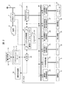
図2は、本実施の形態による複合型電力変換装置(H−PCS)7の構成を示す。本複合型電力変換装置7は、この図2に示すように、エネルギー管理装置(以下、これをEMS(Energy Management System)と呼ぶ)20及びシステム制御装置21と、DC(Direct Current)バス22を介して接続された複数の充放電装置(図2では蓄電池充放電装置23及びEV充放電装置24)及び複数の電力変換装置(図2では太陽光電力変換装置25、風力発電電力変換装置26、燃料電池発電電力変換装置27及びガス発電電力変換装置28)並びに双方向AC/DC(Alternating Current/Direct Current)コンバータ29となどを備えて構成される。
(2) Configuration of Hybrid Power Converter FIG. 2 shows the configuration of the hybrid power converter (H-PCS) 7 according to the present embodiment. As shown in FIG. 2, the composite
EMS20は、CPU(Central Processing Unit)及びメモリ等の情報処理資源を備えたマイクロコンピュータ装置である。このEMS20には、スマートフォン、タブレット又はパーソナルコンピュータ等の通信端末装置30やアグリゲーションサーバ12と通信を行う通信機能と、通信端末装置30を介して需要家3(図1)により設定された運転モードやアグリゲーションサーバ12から与えられる第2の制御指令に従ってシステム制御装置21に対応する指示を与えることにより、必要な電力装置の充放電等を制御する充放電等制御機能とが搭載されている。
The
またEMS20には、交流メータ4から取得した系統2からの電力の電圧及び周波数と、使用電力量とに基づいて、その需要家3における電力消費状態が最適となるようにシステム制御装置21を介して各電力装置の充放電を制御する電力消費最適化機能と、系統2の停電が発生した場合などにその需要家3が所有する電力装置に蓄電された電力又は電力装置が発電する電力を利用して自立して消費電力を賄えるように制御する自立運転制御機能となども搭載されている。
In addition, the
システム制御装置21は、EMS20からの指示に基づいて、双方向AC/DCコンバータ29と、各充放電制御装置(蓄電池充放電装置23及びEV充放電装置24)と、各電力変換装置(太陽光電力変換装置25、風力発電電力変換装置26、燃料電池発電電力変換装置27及びガス発電電力変換装置28)との運転を制御するマイクロコンピュータ装置であり、CPU31、メモリ32、通信インタフェース33及び入出力インタフェース34を備えて構成される。
Based on the instruction from the
CPU31は、システム制御装置21全体の動作制御を司るプロセッサである。またメモリ32は、揮発性又は不揮発性の半導体メモリから構成され、各種プログラムや情報を記憶保持するために利用される。メモリ32に格納されたプログラムをCPU31が実行することにより、後述のようなシステム制御装置21全体としての各種処理が実行される。通信インタフェース33は、EMS20との通信時におけるプロトコル制御を行うインタフェースであり、入出力インタフェース34は、双方向AC/DCコンバータ29や、各充放電装置及び各電力変換装置との通信、入出力時におけるプロトコル制御及び入出力制御を行うインタフェースである。
The
各充放電装置は、システム制御装置21からの指示に応じて、蓄電機能を有する電力装置(図2では蓄電池8又は電気自動車9)の充放電を例えばその容量の0〜100%の範囲で制御する機能を有する制御装置である。充放電装置には、対象とする電力装置の充放電電圧値及び充放電電流値を計測してシステム制御装置21に通知したり、その電力装置の各種情報(蓄電量及びエラーの有無など)をシステム制御装置21に通知する機能も搭載されている。
Each charging/discharging device controls charging/discharging of a power device (
同様に、電力変換装置は、システム制御装置21からの指示に応じて、発電機能を有する対象とする電力装置(図2では太陽光発電設備10、風力発電システム35、燃料電池発電システム36又はガスジェネレータ装置37)により発電された電力をその0〜100%の範囲でDCバス22に放電する機能を有する制御装置である。また電力変換装置には、対象とする電力装置が発電した電力の電圧値及び電流値を計測してシステム制御装置21に通知する機能も搭載されている。
Similarly, the power conversion device is a target power device having a power generation function (in FIG. 2, the photovoltaic
双方向AC/DCコンバータ29は、系統2から与えられる交流電力を直流電力に変換してDCバス22に出力したり、各充放電装置及び各電力変換装置からDCバス22に放電された直流電力を交流電力に変換して系統2に出力する機能を有するコンバータである。双方向AC/DCコンバータ29には、DCバス22から系統2に出力し又は系統2からDCバス22に入力する電力量をDCバス22又は系統2を流れる電力の0〜100%の範囲で制御する機能や、DCバス22に入出力する電力の直流電圧値、直流電流値、及び交流電圧値、交流電流値、交流周波数を計測してシステム制御装置21に通知する機能も搭載されている。
The bidirectional AC/
なお以下においては、説明の容易化のため、図3に示すように、各需要家3がそれぞれ電力装置として蓄電池8、電気自動車9及び太陽光発電設備10を所有し、複合型電力変換装置7が、充放電装置として蓄電池充放電装置23及びEV充放電装置24、電力変換装置として太陽光電力変換装置25を備えるものとする。この場合、蓄電池8及び蓄電池充放電装置23間、電気自動車9及びEV充放電装置24間、太陽光発電設備10及び太陽光電力変換装置25間、並びに、双方向AC/DCコンバータ29及び分電盤5間には、それぞれ安全対策用のスイッチ40〜43が設けられる。
Note that, in the following, for ease of explanation, as shown in FIG. 3, each
また以下においては、複合型電力変換装置7がACコンセント50、自立端子51及びUPS(無停電電源装置:Uninterruptible Power Supply)端子52を備えるものとして説明を進める。この場合、ACコンセント50は、スイッチ44を介して分電盤5及びスイッチ43間に接続され、自立端子51はスイッチ45を介して双方向AC/DCコンバータ29及びスイッチ43間に接続される。またUPS端子52は、DC/ACコンバータ47を介してDCバス22に接続される。
Further, in the following description, it is assumed that the composite
かかる構成を有する本実施の形態の複合型電力変換装置7において、EMS20は、先物情報、実績情報及び定期情報をアグリゲーションサーバ12に送信する。
In the composite
先物情報は、図4に示すように、需要家3が複合型電力変換装置7に設定したその複合型電力変換装置7の当日から1週間分の運転パターンを含む情報であり、例えば1日に1回複合型電力変換装置7からアグリゲーションサーバ12に送信される。図4の例の場合、当日、翌日、2日目、3日目、4日目、5日目及び6日目の複合型電力変換装置7の運転パターンがそれぞれ「EX2」、「EX3」、「EX6」、「EX6」、「EX6」、「EX6」及び「EX3」という運転パターンにそれぞれ設定されていることが示されている。運転パターンの詳細については後述する。
As shown in FIG. 4, the futures information is information including an operation pattern for one week from the current day of the composite
実績情報は、その需要家3の前日の発電電力量、充放電電力量及び電力消費量等に関する情報であり、例えば1日に1回複合型電力変換装置7からアグリゲーションサーバ12に送信される。
The record information is information on the power generation amount, charge/discharge power amount, power consumption amount, and the like of the
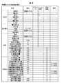
実績情報には、例えば図5に示すように、前日の午前0時から24時までの間の太陽光発電設備10の発電電力量(「PV」の「発電電力量」)と、蓄電池8や電気自動車9の内蔵蓄電池の前日の午前0時から24時までの間の充電電力量(「蓄電池」及び「EV」の「充電電力量」)及び放電電力量(「蓄電池」及び「EV」の「放電電力量」)、並びに、前日の0時現在での蓄電電力量(「蓄電池」及び「EV」の「0時現在電力量」)及び前日の24時現在での蓄電電力量(「蓄電池」及び「EV」の「24時現在電力量」)と、前日の午前0時から24時までの間の系統2から入力した電力量(「系統」の「系統入力電力量」)及び系統2に出力した電力量(「系統」の「系統放電電力量」)、電圧制御による電力の調整量(「系統」の「電圧制御による電力調整量」)、周波数制御による電力の調整量(「系統」の「周波数制御による電力調整量」)及び無効電力の調整量(「系統」の「無効電力調整量」)と、前日の午前0時から24時までの間の負荷6での使用電力量(「負荷」の「使用電力量」)といった情報が含まれる。
For example, as shown in FIG. 5, the record information includes the power generation amount of the photovoltaic power generation facility 10 (“PV” “power generation amount”) from 0:00 to 24:00 the previous day, the
また実績情報には、前日の午前0時から24時までの間における運転モードの初期値(「履歴」の「初期運転モード」)と、前日の午前0時から24時までの間に運転モードが変更された場合の変更後の運転モード(「履歴」の「更新後運転モード」)と、その変更が行われた時刻(「履歴」の「変更時刻」)と、アグリゲーションサーバ12から与えられた第2の制御指示に従って前日の午前0時から24時までの間に系統2に入出力した各電力量(「履歴」の「放電電力量」及び「充電電力量」」)といった情報も含まれる。
In addition, the actual information includes the initial value of the operation mode from "00:00 to 24:00 the previous day" ("Initial operation mode" in "History") and the operation mode from 00:00 to 24:00 the previous day. When the change is made, the changed operation mode (“updated operation mode” in “history”), the time when the change was made (“change time” in “history”), and the
定期情報は、例えば直前の30分間における発電電力量、充放電電力量及び電力消費量等に関する情報であり、30分ごとに複合型電力変換装置7からアグリゲーションサーバ12に送信される。
The periodic information is, for example, information on the generated power amount, the charge/discharge power amount, the power consumption amount, and the like in the last 30 minutes, and is transmitted from the hybrid
定期情報には、例えば図6に示すように、直前の30分間における太陽光発電設備10の発電電力量(「PV」の「発電電力量」)と、蓄電池8や電気自動車9の内蔵蓄電池の直前の30分間における充電電力量(「蓄電池」及び「EV」の「充電電力量」)及び放電電力量(「蓄電池」及び「EV」の「放電電力量」)、定期情報を前回送信した際の蓄電池8や電気自動車9の内蔵蓄電池の蓄電電力量(「蓄電池」及び「EV」の「前回電力量」)及び現在の蓄電電力量(「蓄電池」及び「EV」の「現在電力量」)、並びに、定期情報を前回送信した際の蓄電池8や電気自動車9の内蔵蓄電池の充電率を表すSOC(State of Charge)(「蓄電池」及び「EV」の「前回SOC」)及び現在の電気自動車9の内蔵蓄電池の充電率(「蓄電池」及び「EV」の「現在SOC」)といった情報と、電気自動車9がEV充放電装置24(図3)に接続されているか否かの情報(「EV」の「EV接続」)とが含まれる。
The periodic information includes, for example, as shown in FIG. 6, the power generation amount of the photovoltaic power generation facility 10 (the “power generation amount” of “PV”) and the built-in storage battery of the
また定期情報には、直前の30分間における、系統2から入力した電力量(「系統」の「系統入力電力量」)及び系統2に出力した電力量(「系統」の「系統放電電力量」)、電圧制御による電力の調整量(「系統」の「電圧制御による電力調整量」)、周波数制御による電力の調整量(「系統」の「周波数制御による電力調整量」)及び無効電力の調整量(「系統」の「無効電力調整量」)と、交流メータ4(図3)により測定された系統2における電力の電圧(「系統」の「系統電圧」)、周波数(「系統」の「系統周波数」)と、需要家3の使用電力量(「系統」の「使用電力量」)といった情報も含まれる。
In addition, the periodic information includes the amount of power input from grid 2 ("grid input power" of "grid") and the amount of power output to grid 2 ("grid discharge power of "grid") in the last 30 minutes. ), the amount of power adjustment by voltage control (“power adjustment amount by voltage control” in “Grid”), the amount of power adjustment by frequency control (“power adjustment amount by frequency control” in “Grid”), and reactive power adjustment Amount ("reactive power adjustment amount" of "grid"), voltage of power in
さらに定期情報には、前回定期情報を送信したときの最大の蓄電可能容量(「履歴」の「前回最大容量」)、そのときの平均的な蓄電可能容量(「履歴」の「前回容量」)と、例えば直前の30分間又は1時間における最大の蓄電可能容量(「履歴」の「現在最大容量」)及び現在の蓄電可能容量(「履歴」の「現在容量」)と、前回定期情報を送信したときに設定されていた運転モード(「履歴」の「前回運転モード」)及び現在の運転モード(「履歴」の「現在運転モード」)、直前の30分間においてアグリゲーションサーバ12からの第2の制御指令に基づく運転が行われたか否かを表す情報(「履歴」の「DR稼働/待機」)、直前の30分間に運転モードの変更が行われた場合のその変更が行われた時刻(「履歴」の「変更時刻」)と、以上の電力量等の計測を行った時刻(「履歴」の「計測時刻」)と、アグリゲーションサーバ12から与えられた第2の制御指示に従って前日の午前0時から24時までの間に系統2に入出力した単位時間当たりの電力量(「履歴」の「制御指令による放電量」及び「制御指令による充電量」)と、現在放電可能な電力量(「履歴」の「充電可能量」)及び現在充電可能な電力量(「充電可能量」)といった情報も含まれる。
Furthermore, the periodic information includes the maximum storable capacity when the regular information was transmitted last time ("previous maximum capacity" in "History"), and the average storable capacity at that time ("previous capacity" in "History") And, for example, the maximum chargeable capacity ("Current maximum capacity" in "History") and current chargeable capacity ("Current capacity" in "History") in the last 30 minutes or 1 hour, and the previous periodical information is transmitted. The operation mode (the “previous operation mode” of the “history”) and the current operation mode (the “current operation mode” of the “history”) that were set at the time of the second operation from the
なお定期情報には、以上の情報に加えて、蓄電池8及び電気自動車9の内蔵蓄電池を放電する放電電力量(抑制可能な系統2からの入力電力量含む)を30分単位で数時間分予測した予測値(「系統」の「蓄電池(EV蓄電池含む)放電による系統電力抑制の予測値」)と、蓄電池8及び電気自動車9の内蔵蓄電池を充電することで実現される充電電力(系統2からの入力電力)の増加量を30分単位で数時間分予測した予測値(「系統」の「蓄電池(EV蓄電池含む)充電による系統電力増加の予測値」)といった情報も含まれる。これらの予測値は、過去の実績等に基づいてEMS20(図3)が算出したものである。
In addition to the above information, the periodical information predicts the discharge power amount (including the input power amount from the
(3)アグリゲーションサーバの構成
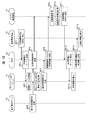
図7は、アグリゲーションサーバ12の概略構成を示す。この図7に示すように、アグリゲーションサーバ12は、上位通信インタフェース60、下位通信インタフェース61、CPU(Central Processing Unit)62、メモリ63及び記憶装置64を備えて構成される。
(3) Configuration of Aggregation Server FIG. 7 shows a schematic configuration of the
上位通信インタフェース60は、発電事業者14(図1)の電力管理サーバ15(図1)との通信時におけるプロトコル制御を行うインタフェースである。また下位通信インタフェース61は、ネットワーク13(図1)を介した各需要家3の複合型電力変換装置7との通信時におけるプロトコル制御を行うインタフェースであり、例えばNIC(Network Interface Card)などから構成される。
The
CPU62は、アグリゲーションサーバ12全体の動作制御を司るプロセッサである。またメモリ63は、例えば半導体メモリから構成され、各種プログラムを一時的に保持するために利用されるほか、CPU62のワークメモリとしても利用される。上述及び後述するデマンドレスポンスに関する各種処理を実行するデマンドレスポンス処理プログラム70もこのメモリ63に格納されて保持される。
The CPU 62 is a processor that controls the operation of the
記憶装置64は、例えばハードディスク装置やSSD(Solid State Drive)などの大容量の不揮発性記憶装置から構成され、各種プログラムやデータを長期間保持するために利用される。本実施の形態の場合、記憶装置64には、需要家初期登録情報データベース71、定期取得情報管理データベース72、出力可能値管理テーブル73、入力可能値管理テーブル74及び実績値テーブル75が格納される。
The
需要家初期登録情報データベース71は、アグリゲータ11(図1)とデマンドレスポンス契約を締結している各需要家3についてそれぞれ初期登録された情報を管理するために利用されるテーブルである。本実施の形態の場合、需要家3について初期登録すべき情報としては、図8に示すように、「契約者」、「契約電力」、「本体」及び「DR設定」の4つの項目がある。
The customer initial
「契約者」は、アグリゲータ11とデマンドレスポンス契約を締結した需要家3(契約者)に関する情報であり、その需要家3に関する初期情報を需要家初期登録情報データベース71に登録した「登録日」と、その需要家3の「個人ID」、「氏名」、「郵便番号」及び「住所」などの情報を含む。
The “contractor” is information regarding the customer 3 (contractor) who has signed the demand response contract with the
また「契約電力」は、その需要家3が電力会社と契約内容に関する情報であり、その電力会社の会社名(「電力会社名」)、その需要家3がその電力会社と締結している契約の「プラン名」及び「容量」と、その契約を行った日(「契約日」)などの情報を含む。
The "contracted electric power" is information about the contract contents of the
「本体」は、その需要家3に設置された複合型電力変換装置7や、その需要家3が所有する各電力装置に関する情報である。その需要家3が電力装置として図3のように蓄電池8、電気自動車9及び太陽光発電設備10を所有している場合、この「本体」に関する情報として、複合型電力変換装置7の「型式」、「設置年月日」、単相用及び三相用のいずれであるかを表す情報(「単相or三相」)、「定格出力」、並びに、交流入力の電圧及び周波数(「交流入力(電圧)」、「交流入力(周波数)」)と、蓄電池8の種別(「蓄電池種別」)、最大電力(「蓄電池最大電力」)及び容量(「蓄電池容量」)と、電気自動車9の種別(「EV種別」)、電気自動車の内蔵蓄電池の最大電力(「EV蓄電池最大電力」)及び容量(「EV蓄電池容量」)と、太陽光発電設備10の種別(「PV種別」)及びその最大発電電力量(「PV最大電力」)となどの情報を含む。
The “main body” is information about the composite
また「DR設定」は、その需要家3がアグリゲータ11と締結したデマンドレスポンス契約に関する情報である。その需要家3が電力装置として図3のように蓄電池8、電気自動車9及び太陽光発電設備10を所有している場合、この「DR設定」に関する情報として、電気自動車9の内蔵蓄電池の充電電力値(「EV充電電力値」)、系統2から得られる電力の最大使用値(「系統使用電力最大値」)、電気自動車9の内蔵蓄電池のSOCの下限値及び上限値(「EV蓄電池SOC下限値」及び「EV蓄電池SOC上限値」)、蓄電池8が充電可能な電力値(「蓄電池充電電力値」)、蓄電池8のSOCの下限値及び上限値(「蓄電池SOC下限値」及び「蓄電池SOC上限値」)、電気自動車9の内蔵蓄電池及び蓄電池8の充放電の優先順位(「EV蓄電池、蓄電池の充放電優先順位」)などの情報を含む。
The “DR setting” is information regarding the demand response contract that the
定期取得情報管理データベース72は、各需要家3の複合型電力変換装置7のEMS20からそれぞれ定期的に送信される図4について上述した先物情報、図5について上述した実績情報及び図6について上述した定期情報を一括管理するために利用されるデータベースである。この定期取得情報管理データベース72は、いずれかの需要家3の複合型電力変換装置7のEMS20から先物情報や、実績情報又は定期情報が送信されてくるごとに更新される。
The regularly acquired
出力可能値管理テーブル73は、各需要家3がそれぞれそのとき系統2に出力可能な電力量を管理し、第1の制御指令に基づくタスクを実行する際に各需要家に割り当てる上述の割当て量を算出するために利用されるテーブルであり、各需要家3の複合型電力変換装置7から30分ごとにそれぞれ送信されてくる定期情報(図6)や、各需要家3の複合型電力変換装置7から適宜送信されてくる図18について後述する予測情報に基づいて順次更新される。この出力可能値管理テーブル73は、図9に示すように、ID欄73A、現在出力欄73B、放電可能容量欄73C及び抑制可能電力量予測値欄73Dを備えて構成される。
The available output value management table 73 manages the amount of electric power that each
そしてID欄73Aには、アグリゲータ11(図1)とデマンドレスポンス契約を締結した各需要家3の複合型電力変換装置7にそれぞれ付与した識別子(ID)が格納される。また現在出力欄73Bには、対応する需要家3が現在系統2に電力を出力している場合の出力電力量が格納され、放電可能容量欄73Cには、対応する需要家3が蓄電池8や電気自動車9の内蔵蓄電池を放電することにより今現在生成可能な電力容量が格納される。
The
また抑制可能電力量予測値欄73Dは、30分ごとの複数時間分の予測値欄73Eに区分されており、各予測値欄73Eには、それぞれ現在時刻から対応する時間の経過後における、対応する需要家3が蓄電池8や電気自動車9の内蔵蓄電池に蓄えた電力をDCバス22に放電することにより放電電力量(抑制可能な系統2からの入力電力量含む)の予測値が格納される。
In addition, the controllable power amount
また入力可能値管理テーブル74は、各需要家3がそれぞれ系統2から入力可能な電力量を管理し、第1の制御指令に基づくタスクを実行する際に各需要家に割り当てる割当て量を算出するために利用されるテーブルであり、各需要家3の複合型電力変換装置7から30分ごとに送信されてくる定期情報(図6)や、各需要家3の複合型電力変換装置7から適宜送信されてくる図18について後述する予測情報に基づいて順次更新される。この入力可能値管理テーブル74は、図10に示すように、ID欄74A、現在入力欄74B、充電可能容量欄74C及び使用可能電力量予測値欄74Dを備えて構成される。
Further, the inputtable value management table 74 manages the amount of electric power that each
そしてID欄74Aには、アグリゲータ11とデマンドレスポンス契約を締結した各需要家3の複合型電力変換装置7にそれぞれ付与した識別子(ID)が格納される。また現在入力欄74Bには、対応する需要家3が現在系統2から電力を入力している場合の入力電力値が格納され、充電可能容量欄74Cには、対応する需要家3が蓄電池8や電気自動車9の内蔵蓄電池に今現在充電能な電力容量が格納される。
The
また使用可能電力量予測値欄74Dは、30分ごとの複数時間分の予測値欄74Eに区分されており、各予測値欄74Eには、それぞれ現在時刻から対応する時間の経過後における、対応する需要家3がDCバス22から蓄電池8や電気自動車9の内蔵蓄電池に充電することにより増加可能な充電電力(系統2から入力電力)の増加量の予測値が格納される。
In addition, the usable power amount
実績値テーブル75(図11)は、各需要家3がそれぞれアグリゲーションサーバ12からの第2の制御指令に従って、蓄電池8や電気自動車9の内蔵蓄電池から系統2に電力を放電した放電量、又は、系統2から入力した電力を蓄電池8や電気自動車9の内蔵蓄電池に充電した充電量を管理するために利用されるテーブルであり、各需要家3の複合型電力変換装置7から30分ごとに送信されてくる定期情報(図6)の一部を抜き出して作成される。この実績値テーブル75は、ID欄75A、日付欄75B、開始時刻欄75C、終了時刻欄75D、放電調整量欄75E及び充電調整量欄75Fを備えて構成される。
The actual value table 75 (FIG. 11) is a discharge amount by which each
そしてID欄75Aには、アグリゲータ11とデマンドレスポンス契約を締結した各需要家3の複合型電力変換装置7にそれぞれ付与した識別子(ID)が格納される。また日付欄75Bには、対応する複合型電力変換装置7がアグリゲーションサーバ12からの第2の制御指令に従って、蓄電池8や電気自動車9の内蔵蓄電池から系統2に電力を放電し、又は、系統2から入力した電力を蓄電池8や電気自動車9の内蔵蓄電池に充電するデマンドレスポンスを最後に行った日付が格納される。
The
さらに開始時刻欄75Cには、そのデマンドレスポンスを開始した時刻(開始時刻)が格納され、終了時刻欄75Dには、そのデマンドレスポンスを終了した時刻(終了時刻)が格納される。また放電調整量欄75Eには、かかるデマンドレスポンスにより蓄電池8や電気自動車9の内蔵蓄電池からDCバス22に放電した放電電力量(系統2への出力電力量)の総和が格納され、充電調整量欄75Fには、かかるデマンドレスポンスによりDCバス22から蓄電池8や電気自動車9の内蔵蓄電池に充電することで増加させた充電電力量(系統2からの入力電力量)の増加量の総和が格納される。
Further, the
(4)運転モード
次に、運転モードについて説明する。図12は、図3について上述した構成を有する複合型電力変換装置7におけるシステム制御装置21のデマンドレスポンスに関する基本的な制御単位をまとめたものである。この図12に示すように、かかるシステム制御装置21の基本的な制御内容として、「入力」、「充電」、「出力」及び「放電」の4つがある。
(4) Operation Mode Next, the operation mode will be described. FIG. 12 is a summary of basic control units regarding the demand response of the
この場合、「入力」としては、系統2から電力をDCバス22に入力する「系統」と、太陽光発電設備10により発電された電力をDCバス22に入力する「PV」との2つがある。そして、システム制御装置21は、「系統」については、図3において「7」、「5」、「4」及び「3」という丸付数字がそれぞれ付された経路をこの順番で経由して系統2からDCバス22に電力を入力するよう双方向AC/DCコンバータ29を動作させることで実現し、「PV」については、図3において「1」、「2」及び「3」という丸付数字がそれぞれ付された経路をこの順番で経由して太陽光発電設備10から電力をDCバス22に入力するよう太陽光電力変換装置25(図3)を動作させることで実現する。
In this case, there are two “inputs”: a “system” that inputs power from the
また「充電」としては、電気自動車9の内蔵蓄電池を充電する「EV充電」と、蓄電池8を充電する「蓄電池充電」との2つがある。そして、システム制御装置21は、「EV充電」については、図3において「3」、「9」及び「8」という丸付数字がそれぞれ付された経路をこの順番で経由して電気自動車9の内蔵蓄電池に電力を供給するようにEV充放電装置24を動作させることで実現し、「蓄電池充電」については、図3において「3」、「11」及び「10」という丸付数字がそれぞれ付された経路をこの順番で経由して蓄電池8に電力を供給するように蓄電池充放電装置23を動作させることで実現する。
There are two types of “charging”: “EV charging” that charges the built-in storage battery of the
「出力」に関しては、系統2に電力を出力する「系統」と、ACコンセント50、自立端子51又はUPS端子52をそれぞれ介して電力を出力する「ACコンセント」、「自立端子」及び「UPS出力」との4つがある。そして、システム制御装置21は、かかる「系統」については、図3において「3」、「4」、「5」及び「7」という丸付数字がそれぞれ付された経路をこの順番で経由して系統2に電力を出力し得るよう双方向AC/DCコンバータ29を動作させることで実現する。
Regarding "output", "system" that outputs electric power to the
またシステム制御装置21は、「ACコンセント」については、図3において「7」、「5」及び「12」という丸付数字がそれぞれ付された経路をこの順番で経由してACコンセント50に電力を出力し得るようにスイッチ44をオン動作することで実現し、「自立端子」については、図3において「3」、「4」及び「13」という丸付数字がそれぞれ付された経路をこの順番で経由して自立端子51に電力を出力し得るようにスイッチ45をオン動作することで実現する。なお「自立端子」は、停電時のみに行われる制御である。さらに「UPS出力」については、図3において「3」及び「14」という丸付数字がそれぞれ付された経路をこの順番で経由してUPS端子52に電力を出力し得るようにスイッチ46をオン動作することで実現する。
In addition, the
また「放電」としては、電気自動車9の内蔵蓄電池を放電させる「EV放電」と、蓄電池8を放電させる「蓄電池放電」との2つがある。そしてシステム制御装置21は、「EV放電」については、図3において「8」、「9」及び「3」という丸付数字がそれぞれ付された経路をこの順番で経由して電気自動車9の内蔵蓄電池に蓄えられた電力をDCバス22に電力を出力するようEV充放電装置24を動作させることで実現し、「蓄電池放電」という制御単位については、図3において「10」、「11」及び「3」という丸付数字がそれぞれ付された経路をこの順番で経由して蓄電池8に蓄えられた電力をDCバス22に出力するように蓄電池充放電装置23を動作させることで実現する。
There are two types of “discharge”: “EV discharge” that discharges the internal storage battery of the
一方、図13は、上述のような制御単位を組み合わせることにより複合型電力変換装置7が実現可能な制御モード(電力の放電元及び当該電力の充電先を規定した動作モード)の種類及びその制御モードを実現するための制御単位の組合せを示す。制御モードとしては、「充電」、「放電」、「自立」及び「無効電力」の4つがある。図13において、制御機能欄の「→」は、その右側の電力装置又は系統2からその左側の電力装置又は系統2への電力の流れを示し、「制御単位組合せ」欄は、対応する制御モードを実現するための図12について上述した制御単位の組合せ方法を示す。
On the other hand, FIG. 13 shows the types of control modes (operation modes that define the discharge source of electric power and the charging destination of the electric power) that can be realized by the combined
例えば「H-PCSエネルギー蓄積制御モード」の「PV+系統→蓄電池」は、太陽光発電設備10により発電した電力と系統2の電力を蓄電池8に充電する制御モードを表しており、これは図12において小文字のローマ数字の「2」という識別子が与えられた制御単位を優先に行い、不足時には小文字のローマ数字の「1」という識別子が与えられた制御単位と組み合わせた制御を加え、図12において小文字のローマ数字の「4」という識別子が与えられた制御単位とを組み合わせる(これら制御単位の制御を同時に行う)ことで実現することが示されている。
For example, “PV+ system→storage battery” in the “H-PCS energy storage control mode” represents a control mode in which the
なお図13において「制御単位組合せ」欄の「小文字のローマ数字「3」と「4」比率制御」は、例えば蓄電池8及び電気自動車9の内蔵蓄電池の容量及び現在のSOCに基づいて充電量を比率分配することを意味する。
Note that in FIG. 13, “lower-case Roman numerals “3” and “4” ratio control” in the “control unit combination” column indicates, for example, the charge amount based on the capacity of the
他方、図14は、運転モードに関する一日のタイムスケジュール例を示す。本実施の形態の場合、「0:00」から「5:00」までの時間帯を「深夜」、「5:00」から「8:00」までの時間帯を「朝」、「8:00」から「12:00」までの時間帯を「午前」、「12:00」から「14:00」までの時間帯を「昼」、「14:00」から「17:00」までの時間帯を「午後」、「17:00」から「19:00」までの時間帯を「夕方」、「19:00」から「24:00」までの時間帯を「夜」として管理する。そして本実施の形態においては、各時間帯に図12について上述した制御モードをそれぞれ割り当てることにより1つの運転モードとして定義する。 On the other hand, FIG. 14 shows an example of a time schedule for one day regarding the operation mode. In the case of the present embodiment, the time zone from “0:00” to “5:00” is “midnight”, the time zone from “5:00” to “8:00” is “morning”, and “8: The time zone from "00" to "12:00" is "am", the time zone from "12:00" to "14:00" is "daytime", and the time zone from "14:00" to "17:00" is The time zone is managed as "afternoon", the time zone from "17:00" to "19:00" as "evening", and the time zone from "19:00" to "24:00" as "night". Then, in the present embodiment, the control modes described above with reference to FIG. 12 are assigned to the respective time zones to define one operation mode.
図15(B)は、このようにして定義された複合型電力変換装置7の幾つかの運転モードの構成例を示す。この図15(B)の例は、図15(A)に示すように、運転パターンとして、「EX1」〜「EX7」の識別子がそれぞれ付与された合計7個の運転パターンが定義された場合の例である。図において、大文字のアルファベットで表す運転モード記号「A」〜「F」は、それぞれ図13について上述した制御モード「a」〜「l」を組み合わせて、複合型電力変換装置7のシステム制御装置21が太陽光発電設備10、蓄電池8及び電気自動車9の内蔵蓄電池などの配下の電力装置を状況に応じて選択し、選択した電力装置を最適に制御する。
FIG. 15B shows a configuration example of some operation modes of the composite
例えば、「A」という識別子が付与された運転モード(「DR優先:アグリゲータの指令の場合」)では、複合型電力変換装置7(システム制御装置21)は、アグリゲーションサーバ12から送信されてきた第2の制御指令に従った運転モード又は制御モードで自律制御を行う。
For example, in the operation mode to which the identifier “A” is assigned (“DR priority: in the case of an aggregator command”), the combined power conversion device 7 (system control device 21) has been transmitted from the
また「B」という識別子が付与された運転モード(「H-PCSエネルギー蓄積制御モード」)では、複合型電力変換装置7(システム制御装置21)は、太陽光発電設備10の発電量の状態、蓄電池8及び電気自動車9の内蔵蓄電池のSOCの状態と充電可能範囲とに応じて、蓄電池8や電気自動車9の内蔵蓄電池に充電させるなど、複合型電力変換装置7の配下にある電力装置にエネルギーを蓄積する制御を行う。そのときの制御モードとしては「a」、「b」、「c」及び「d」の制御モードが存在する。制御処理については後述する。
In addition, in the operation mode (“H-PCS energy storage control mode”) to which the identifier “B” is assigned, the combined power conversion device 7 (system control device 21) displays the state of the power generation amount of the photovoltaic
「C」という識別子が付与された運転モード(「H-PCSエネルギー放出制御モード」)では、複合型電力変換装置7(システム制御装置21)は、太陽光発電設備10の発電量の状態、蓄電池8及び電気自動車9の内蔵蓄電池のSOCの状態と放電可能範囲に応じて、蓄電池8や電気自動車9の内蔵蓄電池から放電するなど、複合型電力変換装置7の配下にある電力装置から蓄積されたエネルギーを放出する制御をする。そのときの制御モードとしては「e」、「f」及び「g」の制御モードが存在する。制御処理については後述する。
In the operation mode (“H-PCS energy release control mode”) to which the identifier “C” is assigned, the combined power conversion device 7 (system control device 21) determines the power generation state of the photovoltaic
「D」という識別子が付与された運転モード(「自立制御モード」)では、複合型電力変換装置7(システム制御装置21)は、停電時に太陽光発電設備10の発電量の状態、蓄電池8及び電気自動車9の内蔵蓄電池のSOCの状態と放電可能範囲とに応じて、蓄電池8や電気自動車9の内蔵蓄電池から放電させ、自立端子51に出力させる。そのときの制御モードとしては「h」、「i」、「j」及び「k」の制御モードが存在する。
In the operation mode (“self-sustaining control mode”) to which the identifier “D” is assigned, the combined power conversion device 7 (system control device 21) causes the power generation state of the photovoltaic
「E」という識別子が付与された運転モード(「ピークカット」)では、複合型電力変換装置7(システム制御装置21)は、系統2からの電力入力の上限値を設定し、これを越える場合に上記「C」の「H-PCSエネルギー放出制御モード」を用いて配下の電力装置の蓄電エネルギーを放電し電力入力を抑制する。そのときの制御モードとしては「e」、「f」及び「g」の制御モードが存在する。
In the operation mode (“peak cut”) to which the identifier “E” is assigned, the combined power converter 7 (system controller 21) sets the upper limit value of the power input from the
「F」という識別子が付与された運転モード(「ピークシフト」)では、複合型電力変換装置7(システム制御装置21)は、価格の安い時間帯あるいは系統電力が過多のときに系統2から入力した電力、及び太陽光発電設備10の発電電力を、上記「B」の「H-PCSエネルギー蓄積制御モード」を用いて蓄電池8及び電気自動車9の内蔵蓄電池に充電するなど、複合型電力変換装置7の配下にある電力装置に蓄積されたエネルギーを増加させる。そのときの制御モードとしては「a」、「b」「c」及び「d」の制御モードが存在する。価格の高い時間帯あるいは系統電力が過少のときに複合型電力変換装置7(システム制御装置21)は、「C」の「H-PCSエネルギー放出制御モード」を用いて配下の電力装置の蓄電エネルギーを放電し電力入力を抑制する。そのときの制御モードとしては「e」、「f」及び「g」の制御モードが存在する。
In the operation mode assigned with the identifier “F” (“peak shift”), the composite power conversion device 7 (system control device 21) inputs from the
一方、「EX1」という識別子の運転パターン(「DR優先:アグリゲータの指令の場合」)は、複合型電力変換装置7(システム制御装置21)は、「深夜」、「朝」、「午前」、「昼」、「午後」、「夕方」及び「夜」のすべての時間帯において、アグリゲーションサーバ12から送信されてきた第2の制御指令に従った運転モード又は制御モードで自律制御を実施する運転パターンである。
On the other hand, regarding the operation pattern of the identifier “EX1” (“DR priority: in the case of aggregator command”), the composite power conversion device 7 (system control device 21) is “midnight”, “morning”, “morning”, Driving that performs autonomous control in the driving mode or the control mode according to the second control command transmitted from the
また「EX2」という識別子が付与された運転パターン(「昼間H-PCSエネルギー蓄積制御モード、夜間放出制御モード」)は、昼間太陽光発電設備10の発電電力を上記「B」の運転モードで複合型電力変換装置7の配下にある電力装置に蓄電し、夜間に上記「C」の運転モードで昼間蓄電したエネルギーを放出する運転パターンである。
In addition, the operation pattern to which the identifier "EX2" is assigned ("daytime H-PCS energy storage control mode, nighttime emission control mode") combines the power generated by the daytime photovoltaic
さらに「EX3」という識別子が付与された運転パターン(「H-PCSエネルギー放出制御モード」)は、「深夜」〜「夜」までの各時間帯に上記「C」の運転モードで蓄電したエネルギーを放出する運転パターンである。 Furthermore, the operation pattern (“H-PCS energy release control mode”) to which the identifier “EX3” is assigned is the energy stored in the above “C” operation mode in each time period from “midnight” to “night”. It is a driving pattern to be released.
「EX4」という識別子が付与された運転パターン(自立制御モード)は、「停電/緊急(BCP(Business continuity planning)/LCP(Life continuity planning)として利用)対応」で、すべての時間帯でその需要家3が所有する太陽光発電設備10、蓄電池8及び電気自動車9の内蔵蓄電池のいずれか1つ又は2つを組み合わせてその需要家3内で自立して電力を賄う(「深夜」から「夜」までの各欄の値が「D」)停電時や緊急時における運転パターンである。
The operation pattern (independent control mode) to which the identifier "EX4" is assigned is "blackout/emergency (use as BCP (Business continuity planning)/LCP (Life continuity planning))", and its demand at all times The solar
「EX5」という識別子が付与された運転パターン(「ピークカット」)は、開始、終了時刻及び系統入力2の上限電力を設定し、上記「C」の「H-PCSエネルギー放出制御モード」を用いて設定した条件を満たす制御を実施し、系統電力の入力制限をする運転パターンである。
For the operation pattern (“peak cut”) to which the identifier “EX5” is assigned, set the start and end times and the upper limit power of
「EX6」という識別子が付与された運転パターン(「ピークシフト」)は、上記「B」の「H-PCSエネルギー蓄電制御モード」を用いて開始、終了時刻を設定し、設定した時間帯に充電を実施し、上記「EX5」と同様の手順で複合型電力変換装置7の配下にある電力装置に蓄積されたエネルギーを放出しピークカットする運転パターンである。
The operation pattern (“Peak shift”) assigned with the identifier “EX6” is set by using the “H-PCS energy storage control mode” of “B” above to set the start and end times and charge during the set time zone. Is performed, and the energy stored in the electric power device under the control of the composite
「EX7」という識別子が付与された運転パターン(「オリジナル設定」)は、各時間帯の運転モードあるいは制御モードを自由に設定(「深夜」から「夜」までのすべての欄の値が「任意」)できる運転パターンである。 The operation pattern (“original setting”) assigned with the identifier “EX7” can be freely set to the operation mode or control mode for each time zone (the values in all columns from “midnight” to “night” are “arbitrary”). )) It is a possible operation pattern.
(5)第1及び第2の制御指令の具体的内容
次に、第1及び第2の制御指令の具体的な内容について説明する。図16は、電力管理サーバ15(図3)からアグリゲーションサーバ12(図3)に送信される第1の制御指令の具体的な内容を示す。図16において、タスク欄80Aは第1の制御指令によるタスクの内容を表し、制御内容欄80Bは、対応するタスク内容の第1の制御指令を受信したアグリゲーションサーバ12により実行される制御内容を示す。また応答時間欄80Cは、対応するタスク内容の第1の制御指令が電力管理サーバ15からアグリゲーションサーバ12に送信される時期を示し、指示値欄80Dは、対応するタスク内容の第1の制御指令に含まれる指示値の内容を示す。さらに実績報告欄80Eは、アグリゲーションサーバから電力管理サーバに通知される対応する第1の制御指令の実行結果の内容を示す。
(5) Specific Contents of First and Second Control Commands Next, specific contents of the first and second control commands will be described. FIG. 16 shows the specific content of the first control command transmitted from the power management server 15 (FIG. 3) to the aggregation server 12 (FIG. 3). In FIG. 16, a
この図16に示すように、第1の制御指令のタスク内容としては、電力需要の多い時間帯の消費電力量を他の時間帯にシフトさせる「ピークシフト」、電力需要の多い時間帯の消費電力量を低減させる「ピークカット」、ネガワットを創出させる「需要側調整1」、ポジワットを創出させる「需要側調整2」、系統2における電力の周波数や電力量を調整する「周波数・電力制御」、無効電力を制御する「無効電力制御」及び各需要家3における太陽光発電電力の逆潮流を禁止する「PV出力の逆潮流防止」などがある。
As shown in FIG. 16, the task contents of the first control command include “peak shift” that shifts the power consumption amount during the time period when the power demand is high to another time period, and consumption during the time period when the power demand is high. "Peak cut" to reduce the amount of power, "
そして「ピークシフト」、「ピークカット」をタスクとした第1の制御指令については、その制御を行うべき日の前日までに電力管理サーバ15からアグリゲーションサーバ12に開始時刻、制御時間及び容量(又は出力)を指示値として指定した第1の制御指令が与えられ、「需要調整1」、「需要調整2」及び「PV出力の逆潮流防止」をタスクとした第1の制御指令については、例えばその制御を行うべき時刻の数分前までに電力管理サーバ15からアグリゲーションサーバ12に開始時刻、制御時間及び容量(又は出力)を指示値として指定した第1の制御指令が与えられる。
Then, for the first control command in which “peak shift” and “peak cut” are tasks, the start time, the control time, and the capacity (or the control time and the capacity (or the capacity) from the
また「周波数・電力制御」、「無効電力制御」をタスクとした第1の制御指令については、リアルタイムで電力管理サーバ15からアグリゲーションサーバ12に開始時刻及び制御時間を指示値として指定した第1の制御指令が与えられる。
As for the first control command having “frequency/power control” and “reactive power control” as tasks, the first control command is specified from the
一方、図17は、電力管理サーバ15から上述の第1の制御指令が与えられたアグリゲーションサーバ12が、需要家3により運転モードとして図15の識別子「A」の運転モードが設定された各複合型電力変換装置7(以下、これを制御対象の複合型電力変換装置7と呼ぶ)に対して送信する第2の制御指令の具体的な内容を示す。
On the other hand, in FIG. 17, each
「ピークシフト」又は「ピークカット」をタスク内容とする第1の制御指令は、前日に電力管理サーバ15からアグリゲーションサーバ12に与えられるため、アグリゲーションサーバ12は、これらのタスク内容の第1の制御指令を受信した場合、図17に示すように、制御対象の各複合型電力変換装置7に対して制御モードと、制御の開始時刻、終了時刻及び容量を指示値として指定した第2の制御指令をそれぞれ送信する。
Since the first control command having “peak shift” or “peak cut” as the task content is given from the
具体的に、アグリゲーションサーバ12は、「ピークシフト」をタスク内容とする第1の制御指令を受信した場合、複合型電力変換装置7の配下にある電力装置にエネルギーを蓄積する「H-PCSエネルギー蓄積」時は制御モードとして図15において識別子が「a」、「b」、「c」、「d」の制御モードを指定すると共に、制御の開始時刻、終了時刻及び容量を指示値として指定した第2の制御指令を制御対象の各複合型電力変換装置7にそれぞれ送信する。同様に複合型電力変換装置7の配下にある電力装置に蓄積されたエネルギーを放出する「H-PCSエネルギー放出」時は、「e」、「f」又は「g」の制御モードが指定される。またアグリゲーションサーバ12は、「ピークカット」をタスク内容とする第1の制御指令を受信した場合、「H-PCSエネルギー放出制御モード」として図15において識別子が「e」、「f」、「g」の制御モードを指定すると共に、制御の開始時刻、終了時刻及び容量を指示値として指定した第2の制御指令を制御対象の各複合型電力変換装置7にそれぞれ送信する。
Specifically, when the
さらにアグリゲーションサーバ12は、「需要調整1」、「需要調整2」、「周波数・電力制御」、「無効電力制御」又は「PV出力の逆潮流防止」をタスク内容とする第1の制御指令は、例えば開始時刻の数分前又はリアルタイムで電力管理サーバ15からアグリゲーションサーバ12に与えられるため、アグリゲーションサーバ12は、これらのタスク内容の第1の制御指令を受信した場合、制御対象の各複合型電力変換装置7に対して制御モードと、指示値として制御の開始時刻、終了時刻及び容量とを指定した第2の制御指令をそれぞれ送信する。
Further, the
アグリゲーションサーバ12は、「需要調整1」をタスク内容とする第1の制御指令を受信した場合、「H-PCSエネルギー蓄積制御モード」として図15において識別子が「a」、「b」、「c」又は「d」の制御モードを指定すると共に、制御の開始時刻及び終了時刻、又は、充電の開始時刻、終了時刻及び充電量を指示値として指定した第2の制御指令を制御対象の各複合型電力変換装置7にそれぞれ送信する。
When the
アグリゲーションサーバ12は、「需要調整2」をタスク内容とする第1の制御指令を受信した場合、「H-PCSエネルギー放出制御モード」として識別子が「e」、「f」又は「g」を指定すると共に、制御の開始時刻、終了時刻及び容量を指示値として指定した第2の制御指令を制御対象の各複合型電力変換装置7にそれぞれ送信する。
When the
さらにアグリゲーションサーバ12は、「周波数・電力制御」をタスク内容とする第1の制御指令を受信した場合、「H-PCSエネルギー制御モード」として、蓄積については図13において識別子が「a」、「b」、「c」又は「d」の制御モードを指定し、放出については図13において識別子が「e」、「f」又は「g」の制御モードを指定すると共に、制御の開始時刻、終了時刻及び容量を指示値として指定した第2の制御指令を制御対象の各複合型電力変換装置7にそれぞれ送信する。なお、第2の制御指令を受信した各複合型電力変換装置7は、蓄積又は放出を予め登録されたグラフに従って周波数変動又は電力変動に応じて実施することになる。
Further, when the
さらにアグリゲーションサーバ12は、「無効電力制御」をタスク内容とする第1の制御指令を受信した場合、制御モードとして図13において識別子が「l」の制御モードを指定した第2の制御指令を制御対象の各複合型電力変換装置7にそれぞれ送信する。
Further, when the
(6)複合型電力変換装置による自律制御の流れ
(6−1)全体の流れ
図18は、本実施の形態による複合型電力変換装置7が、アグリゲーションサーバ12から所定時間(30分ごと)に与えられる第2の制御指令に基づいて、需要家3の各電力装置を第2の制御指令に応じた状態に自律制御する処理の流れを示す。
(6) Flow of Autonomous Control by Combined Power Converter (6-1) Overall Flow FIG. 18 shows that the combined
この場合、アグリゲータ11とデマンドレスポンス契約を締結した各需要家3は、それぞれ通信端末装置30を用いて自己の複合型電力変換装置7が自律して各電力装置を制御するための条件(以下、これを自律制御条件と呼ぶ)を適宜設定する。このとき設定すべき自律制御条件は、蓄電池8の充放電可能範囲(SOC上限値及び下限値)、充電電力値及び放電電力値と、電気自動車9の内蔵蓄電池の充放電可能範囲(SOC上限値及び下限値)、充電電力値及び放電電力値と、蓄電池8及び電気自動車9の内蔵蓄電池の充放電の優先順位及び、今後数時間分の30分ごとの電力使用量の予測値である。そして通信端末装置30は、このようにして需要家3により設定された自律制御条件をEMS20に送信する(SP1)。
In this case, each
EMS20は、通信端末装置30から送信されてきた自律制御条件に基づいて、図9について上述した出力可能値管理テーブル73及び図10について上述した入力可能値管理テーブル74を更新するために必要な情報(例えば30分ごとの予測値)を算出し、算出したこれらの情報を予測情報としてアグリゲーションサーバ12に送信する(SP2)。
The
実際上、EMS20は、通信端末装置30からかかる自律制御条件が送信されてくると、当該自律制御条件に含まれる今後数時間分の30分ごとの電力使用量の予測値に基づいて、今後30分ごとの蓄電池8及び電気自動車9の内蔵蓄電池から系統2に出力可能な電力量を数時間分算出すると共に、今後30分ごとの蓄電池8及び電気自動車9の内蔵蓄電池に充電するために入力可能な電力量を数時間分算出する。
In fact, when the
そしてEMS20は、算出したこれらの電力量を、その需要家3が系統2に現在出力している電力量及びその需要家3が系統2から現在入力している電力量と、かかる蓄電池8及電気自動車9の内蔵蓄電池から系統2に現在放電可能な電力量及びこれらの蓄電池8等に現在充電可能な容量と共に予測情報としてアグリゲーションサーバ12に送信する。
Then, the
この予測情報を受信したアグリゲーションサーバ12は、当該予測情報に基づいて出力可能値管理テーブル73(図9)及び入力可能値管理テーブル74(図10)を更新する(SP3)。なお、上述のように出力可能値管理テーブル73及び入力可能値管理テーブル74は、各需要家3の複合型電力変換装置7から30分ごとにアグリゲーションサーバ12に送信される定期情報(図6)によっても更新される。
The
また、このときEMS20は、ステップSP2で受信した自律制御条件をシステム制御装置21に送信し(SP4)、これをシステム制御装置21に登録する。
Further, at this time, the
以上までの処理は、需要家3が通信端末装置30を用いて自律制御条件を更新するたびに実行される。
The above processing is executed every time the
一方、電力管理サーバ15は、アグリゲーションサーバ12に対して、そのアグリゲーションサーバ12が管理する区域において実行すべきタスクと、その開始時刻、制御時間及び容量とを指定した第1の制御指令を一定時間ごと(例えば30分ごと)に送信する(SP5)。
On the other hand, the
そして、この第1の制御指令を受信したアグリゲーションサーバ12は、第1の制御指令において指定されたタスクを実行するためにそのアグリゲーションサーバ12が管理する区域内の各需要家3に割り当てる電力量(系統2からの入力電力の上限値や、系統2に出力すべき電力の下限値)を出力可能値管理テーブル73や入力可能値管理テーブル74と、また必要に応じて需要家初期登録情報データベース71及び定期取得情報管理データベース72となどを参照してそれぞれ計算する(SP6)。なお、このときかかる対象となる需要家3は、そのときの複合型電力変換装置7の運転モードとして図15において識別子が「EX1」の運転パターンが設定されている各需要家3のみである。
Then, the
そしてアグリゲーションサーバ12は、対応する需要家3ごとに、かかる第1の制御指令において指定されたタスクに応じた運転モード又は制御モードを指定すると共に、上述のようにして計算したその需要家3の割当て量と、かかる運転モード又は制御モードの開示時刻及び終了時刻とを指定値として指定した第2の制御指令を生成し、生成した第2の制御指令をその需要家3の複合型電力変換装置7のEMS20に送信する(SP7)。またEMS20は、かかる第2の制御指令を受信すると、この第2の制御指令に含まれる運転モード又は制御モードと指示値とを制御情報としてシステム制御装置21に転送する(SP8)。
Then, the
システム制御装置21は、かかる制御情報を受信すると、その制御情報において指定された運動モード又は制御モードで、当該制御情報において指定された指示値の条件を満たすように蓄電池充放電装置23(図3)、EV充放電装置24(図3)及び太陽光電力変換装置(図3)のうちの必要な装置の動作を制御する自律制御処理を実行する(SP9)。
Upon receiving the control information, the
具体的に、システム制御装置21は、かかる制御情報において指定された運転モード又は制御モードで必要な充放電装置や電力変換装置を動作させる。またこの際、システム制御装置21は、かかる制御情報に指示値が含まれる場合には、系統2から入力する電力量が指示された割当て量以下となり又は系統2に出力する電力量が指示された割当て量以上となるように対応する電力装置を動作させる。
Specifically, the
また、この際システム制御装置21は、蓄電池8及び電気自動車9の内蔵蓄電池の受放電電力量や、太陽光発電設備10の発電電力量などの必要なデータを蓄電池充放電装置23(図3)、EV充放電装置24(図3)及び太陽光電力変換装置(図3)に計測させる(SP10)。そして、システム制御装置21は、やがてアグリゲーションサーバ12からEMS20を経由して次の指示値が与えられると(例えば30分後)、それまでの計測結果に基づいて図6について上述した定期情報を生成し、生成した定期情報をEMS20に送信する(SP11)。
In addition, at this time, the
EMS20は、かかる定期情報を受信すると、これをアグリゲーションサーバ12に転送する(SP12)。かくして、アグリゲーションサーバ12は、この定期情報に基づいてその期間におけるその需要家の放電調整量又は充電調整量を集計し、集計結果に基づいて定期取得情報管理データベース72(図7)及び実績値テーブル75(図11)をそれぞれ更新する(SP13)。
Upon receiving the regular information, the
またEMS20は、受信したかかる定期情報を通信端末装置30にも転送する(SP14)。かくして、通信端末装置30は、この定期情報をアグリゲーションサーバ12と同様に集計し、集計結果を含む必要な情報を表示する(SP15)。
The
なおステップSP5〜ステップSP15の処理は、電力管理サーバ15(図3)が第1の制御指令をアグリゲーションサーバ12に送信する周期(30分周期)で繰り返される。
The processing of steps SP5 to SP15 is repeated in a cycle (30-minute cycle) in which the power management server 15 (FIG. 3) sends the first control command to the
(6−2)系統入力電力抑制処理
図19A〜図19Cは、アグリゲーションサーバ12から複合型電力変換装置7に送信された第2の制御指令において、例えばアグリゲータから電力入力制限指令があり図15(B)の「A」という運転モードが指定されている場合に、その複合型電力変換装置7のシステム制御装置21により実行される系統入力電力抑制処理の処理手順を示す。
(6-2) System Input Power Suppression Processing FIGS. 19A to 19C show that in the second control command transmitted from the
上述のようにアグリゲーションサーバ12から複合型電力変換装置7に送信された第2の制御指令は、EMS20を経由してシステム制御装置21に与えられる。そしてシステム制御装置21は、かかる第2の制御指令が与えられると、この図19A〜図19Cに示す系統入力電力抑制処理を開始し、まず、交流メータ4を利用して、現在、複合型電力変換装置7が系統2から入力している電力量を計測する(SP20)。
The second control command transmitted from the
続いて、システム制御装置21は、ステップSP20の計測結果に基づいて、現在、複合型電力変換装置7が買電力中であるか否か(ステップSP20で計測した電力量がプラスであるか否か)を判断する(SP21)。そしてシステム制御装置21は、この判断で否定結果すなわち電力出力している判断を得るとDR抑制条件を満足していると判断し、ステップSP37に進む。
Then, based on the measurement result of step SP20, the
これに対して、システム制御装置21は、ステップSP21の判断で肯定結果を得ると、蓄電池8若しくは電気自動車9の内蔵蓄電池からDCバス22に放電し、又は、太陽光発電設備10のDCバス22への出力電力を制御することにより、複合型電力変換装置7が系統2から入力する電力を第2の制御指令において指示値として指定されたDR指令値(以下、これを系統電力抑制値と呼ぶ)以下とするよう蓄電池充放電装置23(図3)、EV充放電装置24(図3)及び又は太陽光電力変換装置25(図3)を制御する(SP22〜SP36)。結果として図15(B)の運転モードCの制御をする。
On the other hand, when the
実際上、システム制御装置21は、ステップSP21の判断で否定結果を得ると、そのとき複合型電力変換装置7が系統2から入力している電力量が第2の制御指令において指定された系統電力抑制値以上であるか否かを判断する(SP22)。そしてシステム制御装置21は、この判断で否定結果すなわちDR抑制を満足している結果を得ると、ステップSP36に進む。
In fact, when the
これに対して、システム制御装置21は、ステップSP22の判断で肯定結果を得ると、電気自動車9の内蔵蓄電池よりも蓄電池8の方が放電の優先順位が高く設定されているか否かを判断する(SP23)。
On the other hand, when the
そしてシステム制御装置21は、この判断で肯定結果を得ると、指定された系統電力抑制値が蓄電池8が放電可能な電力量の範囲内であるか否かを判断する(SP24)。システム制御装置21は、この判断で肯定結果を得ると、第2の制御指令で指定された系統電力抑制値になるまで系統2からの電力入力を抑制するよう双方向AC/DCコンバータ29(図3)に指示を与えると共に、DCバス22の電圧が予め設定された電圧(以下、これをDCバス規定電圧と呼ぶ)とするために必要な電力量を蓄電池8から放電するよう蓄電池充放電装置23に指示を与える第1の入力電力抑制処理を実行し(SP25)、この後、ステップSP36に進む。
Then, when a positive result is obtained in this determination, the
これに対してシステム制御装置21は、ステップSP24の判断で否定結果を得ると、蓄電池8からの放電を停止するよう蓄電池充放電装置23に指示を与える(SP26)。またシステム制御装置21は、第2の制御指令で指定された系統電力抑制値が電気自動車9の内蔵蓄電池が放電可能な電力量の範囲内であるか否かを判断する(SP27)。
On the other hand, when the
システム制御装置21は、この判断で肯定結果を得ると、第2の制御指令で指定された系統電力抑制値になるまで系統2からの電力入力を抑制するよう双方向AC/DCコンバータ29(図3)に指示を与えると共に、DCバス22の電圧が予め設定された電圧(以下、これをDCバス規定電圧と呼ぶ)とするために必要な電力量を電気自動車9の内蔵蓄電池から放電するようEV充放電装置24に指示を与える第2の入力電力抑制処理を実行し(SP28)、この後、ステップSP36に進む。またシステム制御装置21は、ステップSP27の判断で否定結果を得ると、電気自動車9の内蔵蓄電池からの放電を停止するようEV充放電装置24に指示を与え(SP29)、この後ステップSP36に進む。
When the
これに対して、システム制御装置21は、ステップSP23の判断で否定結果を得ると、第2の制御指令で指定された系統電力抑制値が電気自動車9の内蔵蓄電池が放電可能な電力量の範囲内であるか否かを判断する(SP30)。そしてシステム制御装置21は、この判断で肯定結果を得ると、ステップSP25と同様の第1の入力電力抑制処理を実行し(SP31)、この後、ステップSP36に進む。
On the other hand, if the
これに対してシステム制御装置21は、ステップSP30の判断で否定結果を得ると、電気自動車9の内蔵蓄電池からの放電を停止するようEV充放電装置24に指示を与え(SP32)、この後、第2の制御指令で指定された系統電力抑制値が蓄電池8が放電可能な電力量の範囲内であるか否かを判断する(SP33)。
On the other hand, if the
そしてシステム制御装置21は、この判断で肯定結果を得ると、ステップSP28と同様の第2の入力電力抑制処理を実行し(SP34)、この後、ステップSP36に進む。またシステム制御装置21は、ステップSP33の判断で否定結果を得ると、蓄電池8からの放電を停止するよう蓄電池充放電装置23に指示を与え(SP35)、この後、ステップSP36に進む。
When the
次いで、システム制御装置21は、太陽光発電設備10により発電された電力のDCバス22への出力量が最大となるよう太陽光電力変換装置25に指示を与え(SP36)、この後、この系統入力電力抑制処理を終了する。
Next, the
一方、ステップSP21の判断で否定結果を得た場合、現在、複合型電力変換装置7が系統2からの入力(買電力)を行っておらず、逆に、太陽光発電設備10の発電により余剰電力が発生し、その余剰電力を系統2に出力(売電力)している可能性がある。そこで、この場合、システム制御装置21は、予め複合型電力変換装置7から系統2への電力の逆潮流が禁止されているか否かを判断する(SP37)。そしてシステム制御装置21は、この判断で否定結果を得ると、この系統入力電力抑制処理を終了する。
On the other hand, when a negative result is obtained in the determination in step SP21, the composite
これに対してシステム制御装置21は、ステップSP37の判断で肯定結果を得ると、余剰電力を蓄電池8若しくは電気自動車9の内蔵蓄電池に充電し、又は、太陽光発電設備10が発電した電力のDCバス22への出力量を最大にし、系統への電力の逆潮流が発生しないように蓄電池充放電装置23、EV充放電装置24及び又は太陽光電力変換装置25を制御する(SP38〜SP54)、結果として図15(B)の運転モードBの制御をする。
On the other hand, when the
実際上、システム制御装置21は、ステップSP37の判断で肯定結果を得ると、電気自動車9の内蔵蓄電池よりも蓄電池8の方が充電の優先順位が高く設定されているか否かを判断する(SP38)。
In fact, when the
そしてシステム制御装置21は、この判断で肯定結果を得ると、余剰電力量が蓄電池8が充電可能な電力量の範囲内であるか否かを判断する(SP39)。システム制御装置21は、この判断で肯定結果を得ると、系統2への電力入出力がゼロとなるまで蓄電池8の充電電圧を上げるよう蓄電池充放電装置23に指示を与え(SP40)、この後、ステップSP51に進む。
When the
これに対してシステム制御装置21は、ステップSP39の判断で否定結果を得ると、蓄電池8への充電を停止するよう蓄電池充放電装置23に指示を与え(SP41)、この後、余剰電力量が電気自動車9の内蔵蓄電池が充電可能な電力量の範囲内であるか否かを判断する(SP42)。
On the other hand, if the
システム制御装置21は、この判断で肯定結果を得ると、系統2への電力入出力がゼロとなるまで電気自動車9の内蔵蓄電池の充電電圧を上げるようEV充放電装置24に指示を与え(SP43)、この後、ステップSP51に進む。またシステム制御装置21は、ステップSP42の判断で否定結果を得ると、電気自動車9の内蔵蓄電池への充電を停止するようEV充放電装置24に指示を与え(SP44)、この後ステップSP51に進む。
When a positive result is obtained in this determination, the
これに対してシステム制御装置21は、ステップSP38の判断で否定結果を得ると、余剰電力量が電気自動車9の内蔵蓄電池が充電可能な電力量の範囲内であるか否かを判断する(SP45)。そしてシステム制御装置21は、この判断で肯定結果を得ると、系統2への電力入出力がゼロとなるまで電気自動車9の内蔵蓄電池の充電電圧を上げるようEV充放電装置24に指示を与え(SP46)、この後、ステップSP51に進む。
On the other hand, if the
これに対してシステム制御装置21は、ステップSP45の判断で否定結果を得ると、電気自動車9の内蔵蓄電池への充電を停止するようEV充放電装置24に指示を与え(SP47)、この後、余剰電力量が蓄電池8が充電可能な電力量の範囲内であるか否かを判断する(SP48)。
On the other hand, if the
システム制御装置21は、この判断で肯定結果を得ると、系統2への電力入出力がゼロとなるまで蓄電池8の充電電圧を上げるよう蓄電池充放電装置23に指示を与え(SP49)、この後、ステップSP51に進む。これに対してシステム制御装置21は、ステップSP48の判断で否定結果を得ると、蓄電池8への充電を停止するよう蓄電池充放電装置23に指示を与え(SP50)、この後、ステップSP51に進む。
If the
そしてシステム制御装置21は、ステップSP51に進むと、太陽光発電設備10により発電された電力のDCバス22への出力量が最大となるよう太陽光電力変換装置25に指示を与える(SP51)。
Then, when the
続いて、システム制御装置21は、蓄電池充放電装置23に蓄電池8のSOCを問い合わせると共に、EV充放電装置24の電気自動車9の内蔵蓄電池のSOCを問い合わせ、これらの問合せに対する蓄電池充放電装置23やEV充放電装置24からの応答に基づいて、蓄電池8及び電気自動車9の内蔵蓄電池のいずれも満充電となったか否かを判断する(SP52)。
Subsequently, the
そしてシステム制御装置21は、この判断で否定結果を得ると、系統2に対する電力入出力がゼロとなるまで満充電となっていない蓄電池8や電気自動車9の内蔵蓄電池を充電するよう、蓄電池充放電装置23やEV充放電装置24に指示を与える(SP53)。
When the
そしてシステム制御装置21は、やがて蓄電池8及び電気自動車9の内蔵蓄電池の双方が満充電になった場合には、太陽光発電設備10の発電電力のDCバス22への出力を停止するよう太陽光電力変換装置25に指示を与え(SP54)、この後、この系統入力電力抑制処理を終了する。
Then, when both the
(6−3)系統電力出力処理
一方、図20A及び図20Bは、アグリゲーションサーバ12から複合型電力変換装置7に送信された第2の制御指令において、例えばアグリゲータから電力出力指令があり図15(B)の「C」という運転モードが指定されている場合に、その複合型電力変換装置7のシステム制御装置21により実行される系統電力出力処理の処理手順を示す。
(6-3) System power output process On the other hand, in FIGS. 20A and 20B, in the second control command transmitted from the
上述のようにアグリゲーションサーバ12から複合型電力変換装置7に送信された第2の制御指令は、EMS20を経由してシステム制御装置21に与えられる。そしてシステム制御装置21は、かかる第2の制御指令が与えられると、まず、交流メータ4(図3)を利用して、現在、自複合型電力変換装置7が系統2から入力している電力量を計測する(SP60)。
The second control command transmitted from the
続いて、システム制御装置21は、ステップSP60の計測結果に基づいて、現在、複合型電力変換装置7が売電力中であるか否か(ステップSP60で計測した電力量がマイナスであるか否か)を判断する(SP61)。そしてシステム制御装置21は、この判断で否定結果を得ると、この系統電力出力処理を終了する。
Subsequently, the
これに対してシステム制御装置21は、ステップSP61の判断で肯定結果を得ると、系統2に出力している電力の電力量が第2の制御指令において指示値として指定された容量(以下、これを出力指示値と呼ぶ)未満であるか否かを判断する(SP62)。そしてシステム制御装置21は、この判断で否定結果を得るとステップSP77に進む。
On the other hand, when the
これに対してシステム制御装置21は、ステップSP62の判断で肯定結果を得ると、蓄電池8若しくは電気自動車9の内蔵蓄電池からDCバス22に放電し、又は、太陽光発電設備10が発電した電力をDCバス22に出力することにより、系統2への出力電力を第2の制御指令で指定された出力指示値以上とするよう蓄電池充放電装置23、EV充放電装置24及び又は太陽光電力変換装置25を制御する(SP63〜SP76)。
On the other hand, when the
実際上、システム制御装置21は、ステップSP62の判断で肯定結果を得ると、電気自動車9の内蔵蓄電池よりも蓄電池8の方が放電の優先順位が高く設定されているか否かを判断する(SP63)。
In fact, when the
そしてシステム制御装置21は、この判断で肯定結果を得ると、指定された出力指示値が蓄電池8が放電可能な電力量の範囲内であるか否かを判断する(SP64)。システム制御装置21は、この判断で肯定結果を得ると、第2の制御指令で指定された出力指示値になるまで蓄電池8から放電するよう蓄電池充放電装置23に指示を与え(SP65)、この後、ステップSP76に進む。
Then, when a positive result is obtained in this determination, the
これに対してシステム制御装置21は、ステップSP64の判断で否定結果を得ると、蓄電池8からの放電を停止するよう蓄電池充放電装置23に指示を与える(SP66)。またシステム制御装置21は、第2の制御指令で指定された出力指示値が電気自動車9の内蔵蓄電池が放電可能な電力量の範囲内であるか否かを判断する(SP67)。
On the other hand, if the
システム制御装置21は、この判断で肯定結果を得ると、第2の制御指令で指定された出力指示値になるまで電気自動車9の内蔵蓄電池から放電するようEV充放電装置24に指示を与え(SP68)、この後、ステップSP76に進む。またシステム制御装置21は、ステップSP67の判断で否定結果を得ると、電気自動車9の内蔵蓄電池からの放電を停止するようEV充放電装置24に指示を与え(SP69)、この後ステップSP76に進む。
When a positive result is obtained in this determination, the
これに対して、システム制御装置21は、ステップSP63の判断で否定結果を得ると、第2の制御指令で指定された出力指示値が電気自動車9の内蔵蓄電池が放電可能な電力量の範囲内であるか否かを判断する(SP70)。そしてシステム制御装置21は、この判断で肯定結果を得ると、第2の制御指令で指定された出力指示値になるまで電気自動車9の内蔵蓄電池から放電するようEV充放電装置24に指示を与え(SP71)、この後、ステップSP76に進む。
On the other hand, when the
これに対してシステム制御装置21は、ステップSP70の判断で否定結果を得ると、電気自動車9の内蔵蓄電池からの放電を停止するようEV充放電装置24に指示を与え(SP72)、この後、第2の制御指令で指定された出力指示値が蓄電池8が放電可能な電力量の範囲内であるか否かを判断する(SP73)。
On the other hand, if the
そしてシステム制御装置21は、この判断で肯定結果を得ると、第2の制御指令で指定された出力指示値になるまで蓄電池8から放電するよう蓄電池充放電装置23に指示を与え(SP74)、この後、ステップSP76に進む。またシステム制御装置21は、ステップSP73の判断で否定結果を得ると、蓄電池8からの放電を停止するよう蓄電池充放電装置23に指示を与え(SP75)、この後、ステップSP76に進む。
Then, when a positive result is obtained in this determination, the
次いで、システム制御装置21は、太陽光発電設備10により発電された電力のDCバス22への出力量が最大となるよう太陽光電力変換装置25に指示を与え(SP76)、この後、この系統電力出力処理を終了する。
Next, the
一方、ステップSP62の判断で否定結果を得た場合、現在、複合型電力変換装置7が系統2に出力している電力値が第2の制御指令で指定された出力指示値よりも大きいことを意味する。そこで、この場合、システム制御装置21は、現在、複合型電力変換装置7が系統2に出力している電力値と、第2の制御指令で指定された出力指示値との差分である余剰電力を蓄電池8若しくは電気自動車9の内蔵蓄電池に充電することにより、複合型電力変換装置7が系統2に出力している電力量が第2の制御指令で指定された出力指示値となるように蓄電池充放電装置23、EV充放電装置24及び又は太陽光電力変換装置25を制御する(SP77〜SP92)。
On the other hand, when a negative result is obtained in the determination in step SP62, it is determined that the power value currently output by the composite
実際上、システム制御装置21は、ステップSP62の判断で肯定結果を得ると、電気自動車9の内蔵蓄電池よりも蓄電池8の方が充電の優先順位が高く設定されているか否かを判断する(SP77)。
In fact, when the
そしてシステム制御装置21は、この判断で肯定結果を得ると、余剰電力量が蓄電池8が充電可能な電力量の範囲内であるか否かを判断する(SP78)。システム制御装置21は、この判断で肯定結果を得ると、第2の制御指令で指定された出力指示値になるまで系統2への電力を出力するよう双方向AC/DCコンバータ29(図3)に指示を与えると共に、DCバス22の電圧が予め設定された電圧(以下、これをDCバス規定電圧と呼ぶ)とするために必要な電力量を蓄電池8に充電するよう蓄電池充放電装置23に指示を与える第1の電力出力処理を実行し(SP79)、この後、ステップSP90に進む。
Then, when a positive result is obtained in this determination, the
これに対してシステム制御装置21は、ステップSP78の判断で否定結果を得ると、蓄電池8への充電を停止するよう蓄電池充放電装置23に指示を与え(SP80)、この後、余剰電力量が電気自動車9の内蔵蓄電池が充電可能な電力量の範囲内であるか否かを判断する(SP81)。
On the other hand, when the
システム制御装置21は、この判断で肯定結果を得ると、第2の制御指令で指定された出力指示値になるまで系統2への電力を出力するよう双方向AC/DCコンバータ29(図3)に指示を与えると共に、DCバス22の電圧が予め設定された電圧(以下、これをDCバス規定電圧と呼ぶ)とするために必要な電力量を電気自動車9の内蔵蓄電池に充電するようEV充放電装置24に指示を与える第2の電力出力処理を実行し(SP82)、この後、ステップSP90に進む。またシステム制御装置21は、ステップSP81の判断で否定結果を得ると、電気自動車9の内蔵蓄電池への充電を停止するようEV充放電装置24に指示を与え(SP83)、この後ステップSP90に進む。
If the
これに対してシステム制御装置21は、ステップSP77の判断で否定結果を得ると、余剰電力量が電気自動車9の内蔵蓄電池が充電可能な電力量の範囲内であるか否かを判断する(SP84)。そしてシステム制御装置21は、この判断で肯定結果を得ると、ステップSP82と同様の第2の電力出力処理を実行し(SP85)、この後、ステップSP90に進む。
On the other hand, if the
これに対してシステム制御装置21は、ステップSP84の判断で否定結果を得ると、電気自動車9の内蔵蓄電池への充電を停止するようEV充放電装置24に指示を与え(SP86)、この後、余剰電力量が蓄電池8が充電可能な電力量の範囲内であるか否かを判断する(SP87)。
On the other hand, if the
システム制御装置21は、この判断で肯定結果を得ると、ステップSP79と同様の第1の電力出力処理を実行し(SP88)、この後、ステップSP90に進む。これに対してシステム制御装置21は、ステップSP87の判断で否定結果を得ると、蓄電池8への充電を停止するよう蓄電池充放電装置23に指示を与え(SP89)、この後、ステップSP90に進む。
If the
そしてシステム制御装置21は、ステップSP90に進むと、蓄電池充放電装置23に蓄電池8のSOCを問い合わせると共に、EV充放電装置24の電気自動車9の内蔵蓄電池のSOCを問い合わせ、これらの問合せに対する蓄電池充放電装置23やEV充放電装置24からの応答に基づいて、蓄電池8及び電気自動車9の内蔵蓄電池のいずれも満充電となったか否かを判断する(SP90)。
Then, when the
システム制御装置21は、この判断で否定結果を得ると、太陽光発電設備10により発電された電力のDCバス22への出力量が最大となるよう太陽光電力変換装置25に指示を与える(SP91)。そしてシステム制御装置21は、やがて蓄電池8及び電気自動車9の内蔵蓄電池の双方が満充電になった場合には、太陽光発電設備10の発電電力のDCバス22への出力を停止するよう太陽光電力変換装置25に指示を与え(SP92)、この後、この系統電力出力処理を終了する。
When a negative result is obtained in this determination, the
(6−4)入力電力抑制処理
図21は、図19A〜図19Cについて上述した系統入力電力抑制処理のステップSP25、ステップSP28、ステップSP31及びステップSP34においてシステム制御装置21により実行される第1及び第2の入力電力抑制処理の具体的な処理内容を示す。
(6-4) Input Power Suppression Processing FIG. 21 shows first and second steps executed by the
システム制御装置21は、系統入力電力抑制処理のステップSP25、ステップSP28、ステップSP31又はステップSP34に進むと、この図21に示す入力電力抑制処理を開始し、まず、第2の制御指令で指定された系統電力抑制値になるまで系統2からの電力入力を抑制するよう双方向AC/DCコンバータ29(図3)に指示を与える(SP100)。
When the
続いて、システム制御装置21は、双方向AC/DCコンバータ29にDCバス22の電圧を計測させ(SP101)、その計測結果に基づいて、DCバス22の電圧が予め設定されたDCバス規定電圧よりも低いか否かを判断する(SP102)。
Subsequently, the
そしてシステム制御装置21は、この判断で肯定結果を得ると、DCバス22の電圧がDCバス規定電圧となるまで蓄電池8(第1の入力電力抑制処理の場合)又は電気自動車9の内蔵蓄電池(第2の入力電力抑制処理の場合)から放電するよう蓄電池充放電装置23(第1の入力電力抑制処理の場合)又はEV充放電装置24(第2の入力電力抑制処理の場合)に指示を与え(SP103)、この後、この入力電力抑制処理を終了する。
When the
これに対してシステム制御装置21は、ステップSP102の判断で否定結果を得ると、DCバス22の電圧がDCバス規定電圧となるまで蓄電池8(第1の入力電力抑制処理の場合)又は電気自動車9の内蔵蓄電池(第2の入力電力抑制処理の場合)からの放電電圧を減少させるよう蓄電池充放電装置23(第1の入力電力抑制処理の場合)又はEV充放電装置24(第2の入力電力抑制処理の場合)に指示を与え(SP104)、この後、この入力電力抑制処理を終了する。
On the other hand, when the
(6−5)電力出力処理
図22は、図20A及び図20Bについて上述した電力出力制御処理のステップSP79、ステップSP82、ステップSP85及びステップSP88においてシステム制御装置21により実行される第1及び第2の電力出力処理の具体的な処理内容を示す。
(6-5) Power Output Process FIG. 22 is a first and second process executed by the
システム制御装置21は、系統電力出力処理のステップSP79、ステップSP82、ステップSP85又はステップSP88に進むと、この図22に示す電力出力制御処理を開始し、まず、第2の制御指令で指定された出力指示値になるまで系統2に電力を出力するよう双方向AC/DCコンバータ29(図3)に指示を与える(SP110)。
When the
続いて、システム制御装置21は、双方向AC/DCコンバータ29にDCバス22の電圧を計測させ(SP111)、その計測結果に基づいて、DCバス22の電圧が予め設定されたDCバス規定電圧よりも低いか否かを判断する(SP112)。
Subsequently, the
そしてシステム制御装置21は、この判断で肯定結果を得ると、DCバス22の電圧がDCバス規定電圧となるまで蓄電池8(第1の電力出力処理の場合)又は電気自動車9の内蔵蓄電池(第2の電力出力処理の場合)への充電を抑制するよう蓄電池充放電装置23(第1の電力出力処理の場合)又はEV充放電装置24(第2の電力出力処理の場合)に指示を与え(SP113)、この後、この電力出力処理を終了する。
When the
これに対してシステム制御装置21は、ステップSP112の判断で否定結果を得ると、DCバス22の電圧がDCバス規定電圧となるまで蓄電池8(第1の系統電力出力処理の場合)又は電気自動車9の内蔵蓄電池(第2の電力出力処理の場合)への充電を抑制するよう蓄電池充放電装置23(第1の電力出力処理の場合)又はEV充放電装置24(第1の系統電力出力処理の場合)に指示を与え(SP114)、この後、この電力出力処理を終了する。
On the other hand, when the
(7)本実施の形態の効果
以上のように本実施の形態のアグリゲーションシステム1では、電力管理サーバ15からアグリゲーションサーバ12に与えられる第1の制御指令に応じて、アグリゲーションサーバ12が、運転モード又は制御モードと、その需要家3の割当て量(その需要家3が系統2から入力可能な電力の上限値又はその需要家3が系統2に出力すべき電力の下限値)とを指定した第2の制御指令を各需要家3の複合型電力変換装置7にそれぞれ送信し、第2の制御指令を受信した各複合型電力変換装置7が、当該第2の制御指令で指定された運転モード又は制御モードで、系統2に入出力する電力が当該第2の制御指令で指定された割当て量となるように必要な電力装置を制御する。
(7) Effects of this Embodiment As described above, in the
従って、本アグリゲーションシステム1によれば、アグリゲーションサーバ12が需要家3ごとに、かつその需要家3が所有する電力装置ごとに制御する必要がなく、各需要家3に対してそれぞれ1つの第2の制御指令を与えるだけで第1の制御指令において指定されたタスクをアグリゲーションサーバ12全体として実行することができ、その分アグリゲータ側(アグリゲーションサーバ12)の負荷を格段的に低減することができる。
Therefore, according to the
また、この際、アグリゲーションサーバ12は、第2の制御指令において、予め定められた運転モード又は制御モードと調達量とを指定するだけであるため、需要家3ごとに電力装置単位での制御を行うことができ、さらに需要家3全体としても自給自足運転やピークシフト運転及びピークカット運転のほか、オリジナルの運転やより複雑な運転を実行させることができる。
Further, at this time, the
さらに本アグリゲーションシステム1では、各複合型電力変換装置7が先物情報として需要家3により設定された1週間分の運転モードを通知するため、アグリゲータ側においてその期間における電力需要の予測を立て易く、アグリゲータが余裕をもった電力制御を行うことができる。
Furthermore, in the
さらに本アグリゲーションシステム1では、各需要家3に対する制御指令がそれぞれその需要家3の複合型電力変換装置7にのみ与えられると共に、各複合型電力変換装置7が、それぞれその配下にある電力装置の実績や状況をまとめて実績情報(図5)や定期情報(図6)としてアグリゲーションサーバ12に送信するため、アグリゲーションサーバ12の通信負荷を低減させることができると共にアグリゲーションサーバ12及び各需要家3間の通信量を格段的に低減させることができる。
Further, in the
(8)他の実施の形態
なお上述の実施の形態においては、本発明を図1〜図3のように構成されたアグリゲーションシステムに適用するようにした場合について述べたが、本発明はこれに限らず、この他種々の構成を有するVPPシステムに広く適用することができる。
(8) Other Embodiments In the above-described embodiments, the case where the present invention is applied to the aggregation system configured as shown in FIGS. 1 to 3 has been described, but the present invention is not limited to this. Not limited to this, it can be widely applied to VPP systems having various other configurations.
また上述の実施の形態においては、アグリゲーションサーバ12からの第2の制御指令に基づいて配下の電力装置の充放電を制御する制御装置としての機能と、系統2から入力する電力を交流から直流に変換すると共に、電力装置から放電された電力を交流に変換して系統2に出力する電力変換装置としての機能とを1つの複合型電力変換装置7に搭載するようにした場合について述べたが、本発明はこれに限らず、かかる制御装置としての機能を有する装置(制御装置)と、かかる電力変換装置としての機能を有する装置(電力変換装置)とを別個に設けるようにしてもよい。
Further, in the above-described embodiment, the function as the control device that controls the charging and discharging of the power device under the control based on the second control command from the
本発明は、VPPシステムに広く適用することができる。 The present invention can be widely applied to VPP systems.
1……アグリゲーションシステム、2……系統、3……需要家、4……交流メータ、6……負荷、7……複合型電力変換装置、8……蓄電池、9……電気自動車、10……太陽光発電設備、11……アグリゲータ、12……アグリゲーションサーバ、15……電力管理サーバ、20……EMS、21……システム制御装置、29……双方向AC/DCコンバータ、23……蓄電池充放電装置、24……EV充放電装置、25……太陽光電力変換装置、73……出力可能値管理テーブル、74……入力可能値管理テーブル、75……実績値テーブル。 1... Aggregation system, 2... System, 3... Consumer, 4... AC meter, 6... Load, 7... Combined power converter, 8... Storage battery, 9... Electric vehicle, 10... …Solar power generation equipment, 11……Aggregator, 12……Aggregation server, 15……Power management server, 20……EMS, 21……System control device, 29……Bidirectional AC/DC converter, 23……Storage battery Charging/discharging device, 24... EV charging/discharging device, 25... Solar power converter, 73... Outputtable value management table, 74... Inputtable value management table, 75... Actual value table.
Claims (7)
各前記需要家の前記制御装置に対してデマンドレスポンスに関する制御指令をそれぞれ送信するサーバ装置と
を備え、
前記サーバ装置は、
要請されたタスク及び電力の調達量に応じて、前記需要家が前記系統から入力する電力の上限値又は前記需要家が前記系統に出力すべき電力の下限値を前記需要家の割当て量として前記需要家ごとにそれぞれ算出し、各前記需要家の前記制御装置に対して、算出した当該需要家の前記割当て量を指定した前記制御指令をそれぞれ送信し、
各前記制御装置は、
前記系統から入力する電力が前記制御指令において指定された前記割当て量以下となるように又は当該割当て量以上の電力を前記系統に出力するように、対応する前記電力装置の充放電を制御し、
前記制御装置は、
前記系統から入力する前記電力を交流から直流に変換して必要な前記電力装置に充電すると共に、前記電力装置から放電された前記電力を直流から交流に変換して前記系統に出力する電力変換装置であり、
前記サーバ装置は、
前記制御指令において、前記割当て量に加えて、電力の放電元及び当該電力の充電先を規定した制御モード又は複数の前記制御モードの組合せからなる運転モードを指定し、
前記制御装置は、
前記制御指令において指定された前記割当て量の電力を前記系統に入出力するよう、当該制御指令において指定された運転モード又は制御モードで対応する前記電力装置の充放電を制御する
ことを特徴とするアグリゲーションシステム。 A control device that is provided for each consumer and that controls charging and discharging of one or a plurality of subordinate power devices and input and output of electric power to and from the grid, respectively.
A server device that transmits a control command related to demand response to the control device of each customer,
The server device is
Depending on the requested task and the procurement amount of electric power, the upper limit value of the electric power that the customer inputs from the grid or the lower limit value of the electric power that the customer should output to the grid is set as the allocation amount of the customer. Calculated for each consumer, to the control device of each consumer, each of the control commands specifying the calculated allocation amount of the consumer is transmitted,
Each said control device,
In order that the power input from the grid be less than or equal to the assigned amount specified in the control command, or to output power equal to or greater than the assigned amount to the system, the charging/discharging of the corresponding power device is controlled,
The control device is
A power conversion device that converts the electric power input from the system from alternating current to direct current to charge the required power device and converts the electric power discharged from the power device from direct current to alternating current and outputs the power to the system. And
The server device is
In the control command, in addition to the assigned amount, a control mode that defines a discharge source of electric power and a charging destination of the electric power, or an operation mode that is a combination of a plurality of the control modes is specified,
The control device is
Charging/discharging of the corresponding electric power device is controlled in the operation mode or the control mode specified in the control command so that the power of the assigned amount specified in the control command is input to or output from the grid. Aggregation system.
配下の各前記電力装置の状況を定期的に前記サーバ装置に通知し、
前記サーバ装置は、
各前記制御装置から通知される各前記電力装置の状況に応じた前記割当て量を各前記需要家にそれぞれ割り当てる
ことを特徴とする請求項1に記載のアグリゲーションシステム。 The control device is
Periodically notify the server device of the status of each of the power devices under its control,
The server device is
The aggregation system according to claim 1, wherein the allocation amount according to the status of each of the power devices notified from each of the control devices is allocated to each of the customers.
各前記需要家の前記制御装置に対してデマンドレスポンスに関する制御指令をそれぞれ送信するサーバ装置と
を備え、
前記サーバ装置は、
要請されたタスク及び電力の調達量に応じて、前記需要家が前記系統から入力する電力の上限値又は前記需要家が前記系統に出力すべき電力の下限値を前記需要家の割当て量として前記需要家ごとにそれぞれ算出し、各前記需要家の前記制御装置に対して、算出した当該需要家の前記割当て量を指定した前記制御指令をそれぞれ送信し、
各前記制御装置は、
前記系統から入力する電力が前記制御指令において指定された前記割当て量以下となるように又は当該割当て量以上の電力を前記系統に出力するように、対応する前記電力装置の充放電を制御し、
前記制御装置は、
前記系統から入力する前記電力を交流から直流に変換して必要な前記電力装置に充電すると共に、前記電力装置から放電された前記電力を直流から交流に変換して前記系統に出力する電力変換装置であり、
予め複数種類の運転モードが定義され、
前記需要家は、自己の前記制御装置に所望する前記運転モードを設定でき、
前記サーバ装置は、
前記運転モードとして、前記サーバ装置からの前記制御指令を優先する運転モードが設定された前記制御装置の前記需要家に対して前記割当て量を割り当てる
ことを特徴とするアグリゲーションシステム。 A control device that is provided for each consumer and that controls charging and discharging of one or a plurality of subordinate power devices and input and output of electric power to and from the grid, respectively.
A server device that transmits a control command related to demand response to the control device of each customer,
The server device is
Depending on the requested task and the procurement amount of electric power, the upper limit value of the electric power that the customer inputs from the grid or the lower limit value of the electric power that the customer should output to the grid is set as the allocation amount of the customer. Calculated for each consumer, to the control device of each consumer, each of the control commands specifying the calculated allocation amount of the consumer is transmitted,
Each said control device,
In order that the power input from the grid be less than or equal to the assigned amount specified in the control command, or to output power equal to or greater than the assigned amount to the system, the charging/discharging of the corresponding power device is controlled,
The control device is
A power conversion device that converts the electric power input from the system from alternating current to direct current to charge the required power device and converts the electric power discharged from the power device from direct current to alternating current and outputs the power to the system. And
In advance a plurality of types of luck rolling mode is defined,
The consumer can set the operation mode desired for the control device of the customer,
The server device is
An aggregation system, wherein the allocation amount is assigned to the customer of the control device in which an operation mode giving priority to the control command from the server device is set as the operation mode.
前記アグリゲーションシステムは、
需要家ごとにそれぞれ設けられ、配下の1又は複数の各電力装置の充放電と、系統への電力の入出力とをそれぞれ制御する制御装置と、
各前記需要家の前記制御装置に対してデマンドレスポンスに関する制御指令をそれぞれ送信するサーバ装置と
を有し、
前記サーバ装置が、要請されたタスク及び電力の調達量に応じて、前記需要家が前記系統から入力する電力の上限値又は前記需要家が前記系統に出力すべき電力の下限値を前記需要家の割当て量として前記需要家ごとにそれぞれ算出し、各前記需要家の前記制御装置に対して、算出した当該需要家の前記割当て量を指定した前記制御指令をそれぞれ送信する第1のステップと、
各前記制御装置が、前記系統から入力する電力が前記制御指令において指定された前記割当て量以下となるように又は当該割当て量以上の電力を前記系統に出力するように、対応する前記電力装置の充放電を制御する第2のステップと
を備え、
前記制御装置は、
前記系統から入力する前記電力を交流から直流に変換して必要な前記電力装置に充電すると共に、前記電力装置から放電された前記電力を直流から交流に変換して前記系統に出力する電力変換装置であり、
前記第1のステップにおいて、前記サーバ装置は、
前記制御指令において、前記割当て量に加えて、電力の放電元及び当該電力の充電先を規定した制御モード又は複数の前記制御モードの組合せからなる運転モードを指定し、
前記第2のステップにおいて、前記制御装置は、
前記制御指令において指定された前記割当て量の電力を前記系統に入出力するよう、当該制御指令において指定された運転モード又は制御モードで対応する前記電力装置の充放電を制御する
ことを特徴とするアグリゲーションシステムの制御方法。 In the control method of the aggregation system,
The aggregation system is
A control device that is provided for each consumer and that controls charging and discharging of one or a plurality of subordinate power devices and input and output of electric power to and from the grid, respectively.
A server device that transmits a control command related to demand response to the control device of each consumer,
According to the requested task and the procurement amount of electric power, the server device sets the upper limit value of the electric power input from the grid by the customer or the lower limit value of the electric power that the customer should output to the grid to the consumer. A first step of calculating each of the consumers as a quota, and transmitting the control command designating the calculated quota of the consumer to the control device of each consumer,
Each of the control devices, so that the power input from the grid is less than or equal to the allocation amount specified in the control command, or to output the power of the allocation amount or more to the system, the corresponding power device And a second step of controlling charge and discharge,
The control device is
A power conversion device that converts the electric power input from the system from alternating current to direct current to charge the required power device and converts the electric power discharged from the power device from direct current to alternating current and outputs the power to the system. And
In the first step, the server device
In the control command, in addition to the assigned amount, a control mode that defines a discharge source of electric power and a charging destination of the electric power, or an operation mode that is a combination of a plurality of the control modes is specified,
In the second step, the control device
Charging/discharging of the corresponding electric power device is controlled in the operation mode or the control mode specified in the control command so that the power of the assigned amount specified in the control command is input to or output from the grid. Control method of aggregation system.
配下の各前記電力装置の状況を定期的に前記サーバ装置に通知し、
前記第1のステップにおいて、前記サーバ装置は、
各前記制御装置から通知される各前記電力装置の状況に応じた前記割当て量を各前記需要家にそれぞれ割り当てる
ことを特徴とする請求項4に記載のアグリゲーションシステムの制御方法。 The control device is
Periodically notify the server device of the status of each of the power devices under its control,
In the first step, the server device
The control method of the aggregation system according to claim 4, wherein the allocation amount according to the status of each of the power devices notified from each of the control devices is allocated to each of the customers.
前記アグリゲーションシステムは、
需要家ごとにそれぞれ設けられ、配下の1又は複数の各電力装置の充放電と、系統への電力の入出力とをそれぞれ制御する制御装置と、
各前記需要家の前記制御装置に対してデマンドレスポンスに関する制御指令をそれぞれ送信するサーバ装置と
を有し、
前記サーバ装置が、要請されたタスク及び電力の調達量に応じて、前記需要家が前記系統から入力する電力の上限値又は前記需要家が前記系統に出力すべき電力の下限値を前記需要家の割当て量として前記需要家ごとにそれぞれ算出し、各前記需要家の前記制御装置に対して、算出した当該需要家の前記割当て量を指定した前記制御指令をそれぞれ送信する第1のステップと、
各前記制御装置が、前記系統から入力する電力が前記制御指令において指定された前記割当て量以下となるように又は当該割当て量以上の電力を前記系統に出力するように、対応する前記電力装置の充放電を制御する第2のステップと
を備え、
前記制御装置は、
前記系統から入力する前記電力を交流から直流に変換して必要な前記電力装置に充電すると共に、前記電力装置から放電された前記電力を直流から交流に変換して前記系統に出力する電力変換装置であり、
予め複数種類の運転モードが定義され、
前記需要家は、自己の前記制御装置に所望する前記運転モードを設定でき、
前記第1のステップにおいて、前記サーバ装置は、
前記運転モードとして、前記サーバ装置からの前記制御指令を優先する運転モードが設定された前記制御装置の前記需要家に対して前記割当て量を割り当てる
ことを特徴とするアグリゲーションシステムの制御方法。 In the control method of the aggregation system,
The aggregation system is
A control device that is provided for each consumer and that controls charging and discharging of one or a plurality of subordinate power devices and input and output of electric power to and from the grid, respectively.
A server device that transmits a control command related to demand response to the control device of each consumer,
According to the requested task and the procurement amount of electric power, the server device sets the upper limit value of the electric power input from the grid by the customer or the lower limit value of the electric power that the customer should output to the grid to the consumer. A first step of calculating each of the consumers as a quota, and transmitting the control command designating the calculated quota of the consumer to the control device of each consumer,
Each of the control devices, so that the power input from the grid is less than or equal to the allocation amount specified in the control command, or to output the power of the allocation amount or more to the system, the corresponding power device And a second step of controlling charge and discharge,
The control device is
A power conversion device that converts the electric power input from the system from alternating current to direct current to charge the required power device and converts the electric power discharged from the power device from direct current to alternating current and outputs the power to the system. And
In advance a plurality of types of luck rolling mode is defined,
The consumer can set the operation mode desired for the control device of the customer,
In the first step, the server device
The method of controlling an aggregation system, wherein the allocation amount is assigned to the customer of the control device in which an operation mode giving priority to the control command from the server device is set as the operation mode.
前記制御装置の配下には、
対応する需要家が所有する1又は複数の電力装置が存在し、
前記サーバ装置と通信し、前記サーバ装置から与えられた前記制御指令に応じた指示を出力するエネルギー管理装置と、
前記エネルギー管理装置から出力された前記指示に従って配下の1又は複数の前記電力装置のうちの必要な前記電力装置を制御するシステム制御装置と、
系統から入力する前記電力を交流から直流に変換して必要な前記電力装置に充電すると共に、前記電力装置から放電された前記電力を直流から交流に変換して前記系統に出力する電力変換装置と
を備え、
前記サーバ装置は、
要請されたタスク及び電力の調達量に応じて、前記需要家が前記系統から入力する電力の上限値又は前記需要家が前記系統に出力すべき電力の下限値を前記需要家の割当て量として前記需要家ごとにそれぞれ算出し、各前記需要家の前記制御装置に対して、算出した当該需要家の前記割当て量を指定した前記制御指令をそれぞれ送信し、
前記システム制御装置は、
前記系統から入力する電力が前記制御指令において指定された前記割当て量以下となるように又は当該割当て量以上の電力を前記系統に出力するように、対応する前記電力装置の充放電を制御し、
前記サーバ装置は、
前記制御指令において、前記割当て量に加えて、電力の放電元及び当該電力の充電先を規定した制御モード又は複数の前記制御モードの組合せからなる運転モードを指定し、
前記制御装置は、
前記制御指令において指定された前記割当て量の電力を前記系統に入出力するよう、当該制御指令において指定された運転モード又は制御モードで対応する前記電力装置の充放電を制御する
ことを特徴とする制御装置。 In accordance with a control command related to the demand response given from the upper server device, in the control device for controlling the charging and discharging of the power device under the control,
Under the control device,
The corresponding demand house there are one or more power devices owned,
An energy management device that communicates with the server device and outputs an instruction according to the control command given from the server device;
A system control device that controls the necessary power device among one or a plurality of subordinate power devices according to the instruction output from the energy management device;
System while charging to the power device required to convert from AC said power input to DC from integration, the power converter for output to the grid by converting the power discharged from the power unit from direct current to alternating current And
The server device is
Depending on the requested task and the procurement amount of electric power, the upper limit value of the electric power that the customer inputs from the grid or the lower limit value of the electric power that the customer should output to the grid is set as the allocation amount of the customer. Calculated for each consumer, to the control device of each consumer, each of the control commands specifying the calculated allocation amount of the consumer is transmitted,
The system controller is
In order that the power input from the grid be less than or equal to the assigned amount specified in the control command, or to output power equal to or greater than the assigned amount to the system, the charging/discharging of the corresponding power device is controlled,
The server device is
In the control command, in addition to the assigned amount, a control mode that defines a discharge source of electric power and a charging destination of the electric power, or an operation mode that is a combination of a plurality of the control modes is specified,
The control device is
Charging/discharging of the corresponding electric power device is controlled in the operation mode or the control mode specified in the control command so that the power of the assigned amount specified in the control command is input to or output from the grid. Control device.
Priority Applications (5)
| Application Number | Priority Date | Filing Date | Title |
|---|---|---|---|
| JP2016162857A JP6716070B2 (en) | 2016-08-23 | 2016-08-23 | Aggregation system, control method thereof, and control device |
| US16/327,348 US10727784B2 (en) | 2016-08-23 | 2017-08-23 | Aggregation system, control method thereof, and control apparatus |
| EP17843654.9A EP3506446B1 (en) | 2016-08-23 | 2017-08-23 | Aggregation system, and control method and control device for same |
| TW106128541A TWI686032B (en) | 2016-08-23 | 2017-08-23 | Integrated system, its control method and control device |
| PCT/JP2017/030190 WO2018038176A1 (en) | 2016-08-23 | 2017-08-23 | Aggregation system, and control method and control device for same |
Applications Claiming Priority (1)
| Application Number | Priority Date | Filing Date | Title |
|---|---|---|---|
| JP2016162857A JP6716070B2 (en) | 2016-08-23 | 2016-08-23 | Aggregation system, control method thereof, and control device |
Publications (3)
| Publication Number | Publication Date |
|---|---|
| JP2018033213A JP2018033213A (en) | 2018-03-01 |
| JP2018033213A5 JP2018033213A5 (en) | 2019-05-09 |
| JP6716070B2 true JP6716070B2 (en) | 2020-07-01 |
Family
ID=61245008
Family Applications (1)
| Application Number | Title | Priority Date | Filing Date |
|---|---|---|---|
| JP2016162857A Active JP6716070B2 (en) | 2016-08-23 | 2016-08-23 | Aggregation system, control method thereof, and control device |
Country Status (5)
| Country | Link |
|---|---|
| US (1) | US10727784B2 (en) |
| EP (1) | EP3506446B1 (en) |
| JP (1) | JP6716070B2 (en) |
| TW (1) | TWI686032B (en) |
| WO (1) | WO2018038176A1 (en) |
Families Citing this family (22)
| Publication number | Priority date | Publication date | Assignee | Title |
|---|---|---|---|---|
| US10523008B2 (en) | 2015-02-24 | 2019-12-31 | Tesla, Inc. | Scalable hierarchical energy distribution grid utilizing homogeneous control logic |
| WO2018190985A1 (en) * | 2017-04-14 | 2018-10-18 | General Electric Company | A wireless power transceiver device and an associated method thereof |
| JP7011991B2 (en) * | 2018-08-31 | 2022-01-27 | 株式会社日立製作所 | Power demand adjustment system and its method |
| US20210257839A1 (en) * | 2018-10-23 | 2021-08-19 | Mitsubishi Electric Corporation | Grid system, control device, control method for grid system, and power conversion device |
| JP2020108293A (en) * | 2018-12-28 | 2020-07-09 | エナジー・ソリューションズ株式会社 | Power generation control system, power generation control method, server device, and program |
| JP7401845B2 (en) * | 2019-09-26 | 2023-12-20 | 東京電力ホールディングス株式会社 | Posiwatt trading support device and Posiwatt trading method |
| JP7401846B2 (en) * | 2019-09-26 | 2023-12-20 | 東京電力ホールディングス株式会社 | Posiwatt trading support device and Posiwatt trading method |
| JP7351169B2 (en) * | 2019-09-26 | 2023-09-27 | 東京電力ホールディングス株式会社 | Posiwatt trading support device and Posiwatt trading method |
| DE102019130337A1 (en) | 2019-11-11 | 2021-05-12 | Dr. Ing. H.C. F. Porsche Aktiengesellschaft | Load management system and method for regulating such a load management system |
| JP7327111B2 (en) * | 2019-11-26 | 2023-08-16 | 住友電気工業株式会社 | Management device, power adjustable amount estimation method, computer program, and system |
| CN110901421B (en) * | 2019-12-13 | 2021-07-06 | 武汉理工大学 | Intelligent bidirectional dynamic wireless charging system and method |
| WO2021149477A1 (en) | 2020-01-22 | 2021-07-29 | 京セラ株式会社 | Storage battery control device, method for controlling storage battery and storage battery control program |
| JP2023040317A (en) * | 2020-02-26 | 2023-03-23 | パナソニックIpマネジメント株式会社 | Load control system, load control method, program, and load system |
| JP7419916B2 (en) * | 2020-03-25 | 2024-01-23 | 東京電力ホールディングス株式会社 | Power trading support device and power trading method |
| US11535113B2 (en) * | 2020-05-05 | 2022-12-27 | Toyota Motor North America, Inc. | Transport battery recharging via virtual power plant |
| WO2022029924A1 (en) * | 2020-08-05 | 2022-02-10 | 三菱電機株式会社 | Distributed power supply management device |
| JP7456900B2 (en) * | 2020-09-15 | 2024-03-27 | 本田技研工業株式会社 | Power management device and power management system |
| JP7480719B2 (en) | 2021-01-28 | 2024-05-10 | トヨタ自動車株式会社 | Server, power management system, and energy management method |
| TWI770928B (en) * | 2021-04-01 | 2022-07-11 | 低碳動能開發股份有限公司 | Power regulation remote control device and control method |
| CN112865199B (en) * | 2021-04-01 | 2023-01-13 | 北京邮电大学 | Online scheduling method and device for electric vehicle charging demand response |
| KR102655823B1 (en) * | 2021-06-01 | 2024-04-08 | 한국전력공사 | Control apparatus for controlling inveter and power system comprising the same |
| JP7065245B1 (en) | 2021-11-19 | 2022-05-11 | 渋谷 進 | Wind / solar power generation equipment |
Family Cites Families (19)
| Publication number | Priority date | Publication date | Assignee | Title |
|---|---|---|---|---|
| JPS595836B2 (en) | 1975-06-10 | 1984-02-07 | 旭硝子株式会社 | heat storage structure |
| JP2000013924A (en) * | 1998-06-22 | 2000-01-14 | System Soken:Kk | Connected electric automobile |
| CA2623398A1 (en) * | 2005-09-23 | 2007-04-05 | Afs Trinity Power Corporation | Method and apparatus for power electronics and control of plug-in hybrid propulsion with fast energy storage |
| US20090040029A1 (en) * | 2006-08-10 | 2009-02-12 | V2Green, Inc. | Transceiver and charging component for a power aggregation system |
| JPWO2008136094A1 (en) * | 2007-04-24 | 2010-07-29 | 三菱電機株式会社 | Electric drive system and hybrid drive system |
| JP4341712B2 (en) * | 2007-09-10 | 2009-10-07 | トヨタ自動車株式会社 | Charge control device and charge control method for power storage mechanism |
| JP4333798B2 (en) * | 2007-11-30 | 2009-09-16 | トヨタ自動車株式会社 | Charge control device and charge control method |
| US20110047052A1 (en) * | 2009-08-18 | 2011-02-24 | Kevin Terrill Cornish | Method and process for an energy management system for setting and adjusting a minimum energy reserve for a rechargeable energy storage device |
| US8509976B2 (en) | 2010-02-18 | 2013-08-13 | University Of Delaware | Electric vehicle equipment for grid-integrated vehicles |
| JP6178045B2 (en) | 2012-04-16 | 2017-08-09 | 株式会社東芝 | Energy management system, energy management method, program, and server device |
| JP2014064425A (en) * | 2012-09-24 | 2014-04-10 | Toshiba Corp | Power conversion device and program |
| JP6173068B2 (en) * | 2013-06-26 | 2017-08-02 | 京セラ株式会社 | Power suppression method, power management system, and power management program |
| JP6257538B2 (en) * | 2015-01-21 | 2018-01-10 | 三菱電機株式会社 | Electricity supply and demand adjustment request amount determination apparatus and method |
| JP2017085769A (en) * | 2015-10-28 | 2017-05-18 | パナソニックIpマネジメント株式会社 | Power conversion system and control device |
| US10211640B2 (en) * | 2016-07-14 | 2019-02-19 | Koolbridge Solar, Inc. | Adaptive load sharing system |
| US10183583B2 (en) * | 2016-08-03 | 2019-01-22 | Solarcity Corporation | Energy generation and storage system with electric vehicle charging capability |
| US10819269B2 (en) * | 2016-09-09 | 2020-10-27 | Inventus Holdings, Llc | DC integration of photovoltaic and DFIG wind turbine generation with electric storage |
| JP6963397B2 (en) * | 2017-03-03 | 2021-11-10 | 株式会社日立製作所 | Aggregation control system, aggregation control method and control device |
| US11171597B2 (en) * | 2018-07-16 | 2021-11-09 | Abb Schweiz Ag | Wind-solar hybrid power plant |
-
2016
- 2016-08-23 JP JP2016162857A patent/JP6716070B2/en active Active
-
2017
- 2017-08-23 WO PCT/JP2017/030190 patent/WO2018038176A1/en unknown
- 2017-08-23 EP EP17843654.9A patent/EP3506446B1/en active Active
- 2017-08-23 US US16/327,348 patent/US10727784B2/en active Active
- 2017-08-23 TW TW106128541A patent/TWI686032B/en active
Also Published As
| Publication number | Publication date |
|---|---|
| WO2018038176A1 (en) | 2018-03-01 |
| US20190199129A1 (en) | 2019-06-27 |
| TWI686032B (en) | 2020-02-21 |
| US10727784B2 (en) | 2020-07-28 |
| JP2018033213A (en) | 2018-03-01 |
| EP3506446A1 (en) | 2019-07-03 |
| EP3506446B1 (en) | 2021-04-14 |
| EP3506446A4 (en) | 2020-03-25 |
| TW201807917A (en) | 2018-03-01 |
Similar Documents
| Publication | Publication Date | Title |
|---|---|---|
| JP6716070B2 (en) | Aggregation system, control method thereof, and control device | |
| WO2012133274A1 (en) | Electrical storage system and mobile body | |
| JP6430041B2 (en) | Management apparatus and control method | |
| JP6592360B2 (en) | Power management method | |
| JP2009273359A (en) | Power system control method and power system controller using secondary battery | |
| WO2020153443A1 (en) | Energy management system and method for controlling same | |
| JP7257917B2 (en) | power management system | |
| JP6640954B2 (en) | Power control system, control device, and power control method | |
| WO2012057119A1 (en) | Electricity supply system | |
| JP2018007536A (en) | Adaptive energy management scheduling system and method for hybrid energy storage system linked with new renewable energy | |
| JP2014155286A (en) | Facility operation scheduling method | |
| WO2014049173A2 (en) | Method for operating an energy storage entity and an energy storage system | |
| JP7203551B2 (en) | power supply system | |
| JP4192131B2 (en) | Power generation planning method and power generation planning apparatus using secondary battery | |
| JP6091337B2 (en) | Energy management system and operation plan creation method | |
| TWI725606B (en) | Distributed electric energy management method for electric vehicle charging station | |
| US20200211128A1 (en) | System, device, and method for mode-based energy storage | |
| KR101649816B1 (en) | Electricity providing system including battery energy storage system | |
| JP6505460B2 (en) | Power management system, power management method and program | |
| CN102840625A (en) | Method for predicting required heat based on low ebb electricity heating | |
| JP6625181B2 (en) | Management device and control method | |
| JP2020188539A (en) | Pcs controller | |
| JP7123587B2 (en) | power supply system | |
| KR102664227B1 (en) | Grid-connected Photovoltaic -Energy Storage System and Control Method thereof | |
| JP7099379B2 (en) | Battery control device, battery control method and program |
Legal Events
| Date | Code | Title | Description |
|---|---|---|---|
| A521 | Request for written amendment filed |
Free format text: JAPANESE INTERMEDIATE CODE: A523 Effective date: 20190327 |
|
| A621 | Written request for application examination |
Free format text: JAPANESE INTERMEDIATE CODE: A621 Effective date: 20190327 |
|
| A521 | Request for written amendment filed |
Free format text: JAPANESE INTERMEDIATE CODE: A821 Effective date: 20190327 |
|
| A621 | Written request for application examination |
Free format text: JAPANESE INTERMEDIATE CODE: A621 Effective date: 20190327 |
|
| A131 | Notification of reasons for refusal |
Free format text: JAPANESE INTERMEDIATE CODE: A131 Effective date: 20191224 |
|
| A521 | Request for written amendment filed |
Free format text: JAPANESE INTERMEDIATE CODE: A523 Effective date: 20200225 |
|
| TRDD | Decision of grant or rejection written | ||
| A01 | Written decision to grant a patent or to grant a registration (utility model) |
Free format text: JAPANESE INTERMEDIATE CODE: A01 Effective date: 20200407 |
|
| A61 | First payment of annual fees (during grant procedure) |
Free format text: JAPANESE INTERMEDIATE CODE: A61 Effective date: 20200430 |
|
| R150 | Certificate of patent or registration of utility model |
Ref document number: 6716070 Country of ref document: JP Free format text: JAPANESE INTERMEDIATE CODE: R150 |
|
| S111 | Request for change of ownership or part of ownership |
Free format text: JAPANESE INTERMEDIATE CODE: R313117 |
|
| R350 | Written notification of registration of transfer |
Free format text: JAPANESE INTERMEDIATE CODE: R350 |
|
| R250 | Receipt of annual fees |
Free format text: JAPANESE INTERMEDIATE CODE: R250 |
|
| R250 | Receipt of annual fees |
Free format text: JAPANESE INTERMEDIATE CODE: R250 |