JP6710946B2 - Controllers, robots and robot systems - Google Patents
Controllers, robots and robot systems Download PDFInfo
- Publication number
- JP6710946B2 JP6710946B2 JP2015235250A JP2015235250A JP6710946B2 JP 6710946 B2 JP6710946 B2 JP 6710946B2 JP 2015235250 A JP2015235250 A JP 2015235250A JP 2015235250 A JP2015235250 A JP 2015235250A JP 6710946 B2 JP6710946 B2 JP 6710946B2
- Authority
- JP
- Japan
- Prior art keywords
- image
- reference marker
- marker
- robot
- imaging unit
- Prior art date
- Legal status (The legal status is an assumption and is not a legal conclusion. Google has not performed a legal analysis and makes no representation as to the accuracy of the status listed.)
- Active
Links
Images


Classifications
-
- B—PERFORMING OPERATIONS; TRANSPORTING
- B25—HAND TOOLS; PORTABLE POWER-DRIVEN TOOLS; MANIPULATORS
- B25J—MANIPULATORS; CHAMBERS PROVIDED WITH MANIPULATION DEVICES
- B25J9/00—Programme-controlled manipulators
- B25J9/16—Programme controls
- B25J9/1679—Programme controls characterised by the tasks executed
- B25J9/1692—Calibration of manipulator
-
- B—PERFORMING OPERATIONS; TRANSPORTING
- B25—HAND TOOLS; PORTABLE POWER-DRIVEN TOOLS; MANIPULATORS
- B25J—MANIPULATORS; CHAMBERS PROVIDED WITH MANIPULATION DEVICES
- B25J9/00—Programme-controlled manipulators
- B25J9/16—Programme controls
-
- B—PERFORMING OPERATIONS; TRANSPORTING
- B25—HAND TOOLS; PORTABLE POWER-DRIVEN TOOLS; MANIPULATORS
- B25J—MANIPULATORS; CHAMBERS PROVIDED WITH MANIPULATION DEVICES
- B25J19/00—Accessories fitted to manipulators, e.g. for monitoring, for viewing; Safety devices combined with or specially adapted for use in connection with manipulators
-
- B—PERFORMING OPERATIONS; TRANSPORTING
- B25—HAND TOOLS; PORTABLE POWER-DRIVEN TOOLS; MANIPULATORS
- B25J—MANIPULATORS; CHAMBERS PROVIDED WITH MANIPULATION DEVICES
- B25J9/00—Programme-controlled manipulators
- B25J9/16—Programme controls
- B25J9/1694—Programme controls characterised by use of sensors other than normal servo-feedback from position, speed or acceleration sensors, perception control, multi-sensor controlled systems, sensor fusion
- B25J9/1697—Vision controlled systems
-
- G—PHYSICS
- G06—COMPUTING; CALCULATING OR COUNTING
- G06T—IMAGE DATA PROCESSING OR GENERATION, IN GENERAL
- G06T7/00—Image analysis
- G06T7/80—Analysis of captured images to determine intrinsic or extrinsic camera parameters, i.e. camera calibration
-
- G—PHYSICS
- G06—COMPUTING; CALCULATING OR COUNTING
- G06V—IMAGE OR VIDEO RECOGNITION OR UNDERSTANDING
- G06V40/00—Recognition of biometric, human-related or animal-related patterns in image or video data
- G06V40/20—Movements or behaviour, e.g. gesture recognition
- G06V40/28—Recognition of hand or arm movements, e.g. recognition of deaf sign language
-
- G—PHYSICS
- G06—COMPUTING; CALCULATING OR COUNTING
- G06T—IMAGE DATA PROCESSING OR GENERATION, IN GENERAL
- G06T2207/00—Indexing scheme for image analysis or image enhancement
- G06T2207/30—Subject of image; Context of image processing
- G06T2207/30108—Industrial image inspection
-
- G—PHYSICS
- G06—COMPUTING; CALCULATING OR COUNTING
- G06T—IMAGE DATA PROCESSING OR GENERATION, IN GENERAL
- G06T2207/00—Indexing scheme for image analysis or image enhancement
- G06T2207/30—Subject of image; Context of image processing
- G06T2207/30204—Marker
- G06T2207/30208—Marker matrix
Landscapes
- Engineering & Computer Science (AREA)
- Mechanical Engineering (AREA)
- Robotics (AREA)
- Physics & Mathematics (AREA)
- Computer Vision & Pattern Recognition (AREA)
- Theoretical Computer Science (AREA)
- General Physics & Mathematics (AREA)
- Human Computer Interaction (AREA)
- Health & Medical Sciences (AREA)
- Multimedia (AREA)
- Social Psychology (AREA)
- Psychiatry (AREA)
- General Health & Medical Sciences (AREA)
- Manipulator (AREA)
Description
本発明は、制御装置、ロボットおよびロボットシステムに関するものである。 The present invention relates to a control device, a robot and a robot system.
従来から、例えば電子部品等の対象物の把持、搬送および組立て等の作業で用いられるロボットシステムが知られている。このようなロボットシステムは、複数のアームを有するロボットアームおよびその先端に設けられたハンドを有するロボットと、カメラ等の撮像部と、ロボットおよび撮像部をそれぞれ制御する制御装置と、を有する。このような構成のロボットシステムは、例えば、撮像部で撮像した対象物の画像を基にして、ロボットがハンドにより対象物に対して各種作業を行う。 2. Description of the Related Art Conventionally, there is known a robot system used for operations such as grasping, carrying, and assembling an object such as an electronic component. Such a robot system includes a robot arm having a plurality of arms and a robot having a hand provided at the tip thereof, an imaging unit such as a camera, and a control device that controls the robot and the imaging unit. In the robot system having such a configuration, for example, the robot performs various operations on the target object with the hand based on the image of the target object captured by the imaging unit.
ここで、撮像部で撮像した画像を基にして、ロボットが対象物に対して的確に作業を行うためには、撮像部で撮像した対象物の画像上の位置および姿勢をロボット座標系における値に変換するための補正パラメーターを求める撮像部の校正(キャリブレーション)が必要である。 Here, in order for the robot to accurately work on the target based on the image captured by the image capturing unit, the position and orientation on the image of the target captured by the image capturing unit are set as values in the robot coordinate system. It is necessary to calibrate the image pickup unit to obtain a correction parameter for converting into.
例えば、特許文献1には、ロボット−視覚センサシステム(ロボットシステム)を用いて、画像上の位置をロボット座標系の値に変換するパラメーターを求める処理について記載されている。特許文献1に記載のロボット−視覚センサシステムは、ロボットアームおよびその先端に設けられたタッチアップ用ハンドを有するロボットと、ロボットアームの先端に設けられた視覚センサー(撮像部)と、3つの基準点および4つの参照点を有する平面を備えるキャリブレーション治具と、を有する。
For example,
特許文献1に記載の処理では、まず、3つの基準点にタッチアップ用ハンドを接触させることにより、ロボット座標系におけるキャリブレーション治具の位置および姿勢を特定する。その後、ロボットアームを駆動して視覚センサーで4つの参照点を撮像して、撮像部の画像座標系でキャリブレーション治具の位置を特定することによって、画像上の位置をロボット座標系の値に変換するパラメーターを求めている。
In the process described in
しかし、特許文献1に記載の処理では、前述したように、3つの基準点にタッチアップ用ハンドを接触させることにより、ロボット座標系におけるキャリブレーション治具の位置を特定している。このような従来の校正の処理では、一般的に、作業者がキャリブレーション治具とタッチアップ用ハンドとの接触を確認するため、作業者によって接触の判断に差が生じてしまう。そのため、キャリブレーション治具の位置および姿勢を高精度に特定することが難しい。
However, in the process described in
また、作業者によって接触の判断を正確に行おうとすると、キャリブレーション治具の位置および姿勢の特定に長時間を要するという問題がある。そのため、校正対象であるロボットの数が増えるほど、前記問題が深刻になる。 In addition, if an operator tries to determine the contact accurately, there is a problem that it takes a long time to specify the position and orientation of the calibration jig. Therefore, the problem becomes more serious as the number of robots to be calibrated increases.
本発明は、上述の課題の少なくとも一部を解決するためになされたものであり、以下の本発明により実現することが可能である。 The present invention has been made to solve at least a part of the above problems, and can be realized by the following present invention.
本発明の制御装置は、ロボットアームを有するロボットと、第1基準マーカー、第2基準マーカーおよび第3基準マーカーを撮像することが可能な撮像部とをそれぞれ制御することが可能な制御装置であって、
前記撮像部と、前記第1基準マーカー、前記第2基準マーカーおよび前記第3基準マーカーとのいずれか一方が前記ロボットに対して設けられ、前記ロボットアームの姿勢を変化させることにより、前記撮像部と、前記第1基準マーカー、前記第2基準マーカーおよび前記第3基準マーカーのそれぞれとの間の距離を変化させることが可能であり、
前記撮像部で前記第1基準マーカーを撮像した第1画像と、前記撮像部で前記第1基準マーカーとは異なる位置に配置された前記第2基準マーカーを撮像した第2画像と、前記撮像部で前記第1基準マーカーおよび前記第2基準マーカーとは異なる位置に配置された前記第3基準マーカーを撮像した第3画像と、に基づいて、前記第1基準マーカー、前記第2基準マーカーおよび前記第3基準マーカーを通る平面と平行な基準面の姿勢を求めることを特徴とする。
The control device of the present invention is a control device capable of controlling a robot having a robot arm and an imaging unit capable of imaging the first reference marker, the second reference marker, and the third reference marker, respectively. hand,
One of the first reference marker, the second reference marker, and the third reference marker is provided for the robot, and the imaging unit is configured by changing the posture of the robot arm. And it is possible to change the distance between each of the first reference marker, the second reference marker and the third reference marker,
A first image obtained by taking an image of the first reference marker by the image pickup unit, a second image obtained by taking an image of the second reference marker arranged at a position different from the first reference marker by the image pickup unit, and the image pickup unit And a third image obtained by imaging the third reference marker arranged at a position different from the first reference marker and the second reference marker, and the first reference marker, the second reference marker, and the third reference image. It is characterized in that the posture of a reference plane parallel to the plane passing through the third reference marker is obtained.
このような制御装置によれば、撮像部で撮像した画像(第1画像、第2画像および第3画像)を基にして基準面の姿勢を求めることができるため、従来のように、作業者による校正用部材(キャリブレーション治具)への接触の判断によって基準面の姿勢を求めることよりも、人為的な誤差や作業者によるバラツキを低減することができる。また、基準面の姿勢を非接触で求めることができるため、例えば、校正用部材の材質等によって基準面の姿勢が変化することを回避できる。このようなことから、本発明の制御装置によれば、基準面の姿勢を高精度に求めることができる。また、本発明の制御装置によれば、撮像部で撮像した画像を基にして基準面の姿勢を求めることができるため、従来よりも基準面の姿勢を容易かつ迅速に求めることができる。 According to such a control device, the posture of the reference plane can be obtained based on the images (first image, second image, and third image) captured by the image capturing unit. It is possible to reduce human errors and variations due to the operator, as compared with the case where the posture of the reference surface is obtained by determining the contact with the calibration member (calibration jig) by. Further, since the attitude of the reference plane can be obtained in a non-contact manner, it is possible to avoid changing the attitude of the reference plane due to, for example, the material of the calibration member. Therefore, according to the control device of the present invention, the attitude of the reference plane can be obtained with high accuracy. Further, according to the control device of the present invention, the posture of the reference plane can be obtained based on the image captured by the image capturing unit, so that the posture of the reference plane can be obtained more easily and quickly than in the past.
本発明の制御装置では、前記第1画像を撮像した際のロボット座標系における前記ロボットの任意の部位の座標と、前記第2画像を撮像した際の前記ロボット座標系における前記部位の座標と、前記第3画像を撮像した際の前記ロボット座標系における前記部位の座標と、に基づいて前記姿勢を求めることが好ましい。 In the control device of the present invention, the coordinates of an arbitrary part of the robot in the robot coordinate system when capturing the first image, and the coordinates of the part in the robot coordinate system when capturing the second image, It is preferable that the posture is obtained based on the coordinates of the part in the robot coordinate system when the third image is captured.
これにより、ロボットの任意の部位(例えば、軸座標)を含む基準面の姿勢を特定することができる。そのため、基準面でロボットが各種作業を行うことで、ロボットは、撮像部で撮像した画像を基にして各種作業を的確に行うことができる。 Thereby, the posture of the reference plane including an arbitrary part (for example, axis coordinates) of the robot can be specified. Therefore, when the robot performs various tasks on the reference plane, the robot can appropriately perform various tasks based on the image captured by the image capturing unit.
本発明の制御装置では、前記第1画像における前記第1基準マーカーの大きさと、前記第2画像における前記第2基準マーカーの大きさと、前記第3画像における前記第3基準マーカーの大きさとに基づいて、前記姿勢を求めることが好ましい。 In the control device of the present invention, based on the size of the first reference marker in the first image, the size of the second reference marker in the second image, and the size of the third reference marker in the third image. Then, it is preferable to obtain the posture.
これにより、撮像部で撮像した画像を基にして基準面の姿勢を的確に求めることができる。 Thereby, the posture of the reference plane can be accurately obtained based on the image captured by the image capturing unit.
本発明の制御装置では、前記第1基準マーカー、前記第2基準マーカーおよび前記第3基準マーカーのそれぞれの大きさが、互いに等しい場合、
前記撮像部に、前記第1画像における前記第1基準マーカーの大きさと、前記第2画像における前記第2基準マーカーの大きさと、前記第3画像における前記第3基準マーカーの大きさとが等しくなるように、前記第1画像、前記第2画像および前記第3画像を撮像させることが好ましい。
In the control device of the present invention, when the respective sizes of the first reference marker, the second reference marker and the third reference marker are equal to each other,
In the imaging unit, the size of the first reference marker in the first image, the size of the second reference marker in the second image, and the size of the third reference marker in the third image are equal. It is preferable that the first image, the second image, and the third image are captured.
これにより、撮像部で撮像した画像を基にして基準面の姿勢を容易かつ迅速に求めることができる。 This makes it possible to easily and quickly obtain the attitude of the reference plane based on the image captured by the image capturing unit.
本発明の制御装置では、前記第1基準マーカー、前記第2基準マーカーおよび前記第3基準マーカーが、それぞれ、所定の間隔で配置された複数のマーカーを有する構成であり、
前記第1画像における前記第1基準マーカーが有する前記複数のマーカー同士の第1間隔と、前記第2画像における前記第2基準マーカーが有する前記複数のマーカー同士の第2間隔と、前記第3画像における前記第3基準マーカーが有する前記複数のマーカー同士の第3間隔とに基づいて、前記姿勢を求めることが好ましい。
In the control device of the present invention, each of the first reference marker, the second reference marker and the third reference marker has a plurality of markers arranged at predetermined intervals,
A first interval between the plurality of markers included in the first reference marker in the first image, a second interval between the plurality of markers included in the second reference marker in the second image, and the third image It is preferable to determine the posture based on the third interval between the plurality of markers included in the third reference marker in.
これにより、第1基準マーカー、第2基準マーカーおよび第3基準マーカーのそれぞれに対して焦点を厳密に合わせる処理をせずとも、基準面の姿勢を求めることができる。 Thereby, the posture of the reference plane can be obtained without performing the process of strictly focusing on each of the first reference marker, the second reference marker, and the third reference marker.
本発明の制御装置では、前記第1基準マーカーの前記第1間隔と、前記第2基準マーカーの前記第2間隔と、前記第3基準マーカーの前記第3間隔とが、等しい場合、
前記撮像部に、前記第1画像における前記第1間隔と、前記第2画像における前記第2間隔と、前記第3画像における前記第3間隔とが等しくなるように、前記第1画像、前記第2画像および前記第3画像を撮像させることが好ましい。
In the control device of the present invention, when the first interval of the first reference marker, the second interval of the second reference marker, and the third interval of the third reference marker are equal,
The first image, the second image, the second image, the second image, and the third image are arranged in the image pickup unit so that the first image, the second image, and the third image are equal to each other. It is preferable to capture two images and the third image.
これにより、第1基準マーカー、第2基準マーカーおよび第3基準マーカーのそれぞれに対して焦点を合わせる処理をせずとも、基準面の姿勢を容易かつ迅速に求めることができる。 Accordingly, the posture of the reference plane can be easily and quickly obtained without performing the process of focusing on each of the first reference marker, the second reference marker, and the third reference marker.
本発明の制御装置では、前記基準面は、前記撮像部の光軸に対して直交していることが好ましい。 In the control device of the present invention, it is preferable that the reference surface is orthogonal to the optical axis of the image capturing unit.
これにより、撮像部の光軸に対して直交している基準面に対してロボットが各種作業を行うことで、ロボットは、撮像部で撮像した画像を基にして各種作業を的確に行うことができる。また、撮像部の画像座標系とロボット座標系との関係を求める処理を容易に行うことができる。 As a result, the robot performs various tasks on the reference plane that is orthogonal to the optical axis of the image capturing section, so that the robot can accurately perform various tasks based on the image captured by the image capturing section. it can. Further, it is possible to easily perform the process of obtaining the relationship between the image coordinate system of the image pickup unit and the robot coordinate system.
本発明の制御装置では、前記第1画像に基づいて求めた前記第1基準マーカーと前記撮像部の撮像基準点との間の第1距離と、前記第2画像に基づいて求めた前記第2基準マーカーと前記撮像基準点との間の第2距離と、前記第3画像に基づいて求めた前記第3基準マーカーと前記撮像基準点との間の第3距離とに基づいて前記姿勢を求めることが好ましい。 In the control device of the present invention, the first distance between the first reference marker obtained based on the first image and the imaging reference point of the imaging unit, and the second distance obtained based on the second image. The posture is obtained based on a second distance between the reference marker and the imaging reference point and a third distance between the third reference marker and the imaging reference point obtained based on the third image. Preferably.
これにより、第1基準マーカー、第2基準マーカーおよび第3基準マーカーのそれぞれに対して焦点を合わせる処理をせずとも、基準面の姿勢を求めることができる。 Thereby, the posture of the reference plane can be obtained without performing the process of focusing on each of the first reference marker, the second reference marker, and the third reference marker.
本発明の制御装置では、前記第1距離、前記第2距離および前記第3距離は、等しいことが好ましい。 In the control device of the present invention, it is preferable that the first distance, the second distance, and the third distance are equal.
これにより、第1基準マーカー、第2基準マーカーおよび第3基準マーカーのそれぞれに対して焦点を合わせる処理をせずとも、基準面の姿勢を容易かつ迅速に求めることができる。 Accordingly, the posture of the reference plane can be easily and quickly obtained without performing the process of focusing on each of the first reference marker, the second reference marker, and the third reference marker.
本発明の制御装置では、前記基準面の原点を求めることが好ましい。
これにより、基準面の原点を特定することで、作業者が基準面の位置を把握し易くなる。
In the control device of the present invention, it is preferable to find the origin of the reference plane.
This makes it easier for the operator to grasp the position of the reference plane by specifying the origin of the reference plane.
本発明の制御装置では、前記撮像部は、前記撮像部は、第4基準マーカーを撮像することが可能であり、
前記第1基準マーカーと前記第2基準マーカーとを通る第1直線と、前記第3基準マーカーと前記第4基準マーカーとを通る第2直線とが交差するように配置されている場合、
前記撮像部に、前記第1基準マーカー、前記第2基準マーカー、前記第3基準マーカーおよび前記第4基準マーカーをそれぞれ撮像させ、
前記第1基準マーカーを撮像した際のロボット座標系における前記第1基準マーカーの座標と、前記第2基準マーカーを撮像した際の前記ロボット座標系における前記第2基準マーカーの座標と、前記第3基準マーカーを撮像した際の前記ロボット座標系における前記第3基準マーカーの座標と、前記第4基準マーカーを撮像した際の前記ロボット座標系における前記第4基準マーカーの座標とから前記第1直線および前記第2直線を求め、求めた前記第1直線および前記第2直線に基づいて、前記ロボット座標系における前記基準面の原点を求めることが好ましい。
これにより、基準面の原点を容易に求めることができる。
In the control device of the present invention, the image capturing unit can capture an image of the fourth reference marker,
When a first straight line passing through the first reference marker and the second reference marker and a second straight line passing through the third reference marker and the fourth reference marker are arranged to intersect with each other,
Causing the imaging unit to image the first reference marker, the second reference marker, the third reference marker, and the fourth reference marker,
The coordinates of the first reference marker in the robot coordinate system when the first reference marker is imaged, the coordinates of the second reference marker in the robot coordinate system when the second reference marker is imaged, and the third From the coordinates of the third reference marker in the robot coordinate system when the reference marker is imaged and the coordinates of the fourth reference marker in the robot coordinate system when the fourth reference marker is imaged, the first straight line and It is preferable that the second straight line is obtained and the origin of the reference plane in the robot coordinate system is obtained based on the obtained first straight line and the second straight line.
Thereby, the origin of the reference plane can be easily obtained.
本発明のロボットは、本発明の制御装置によって制御されることを特徴とする。
このようなロボットによれば、各種作業を的確に行うことができる。
The robot of the present invention is controlled by the control device of the present invention.
According to such a robot, various works can be performed accurately.
本発明のロボットシステムは、本発明の制御装置と、当該制御装置によって制御されるロボットと、撮像する機能を有する撮像部とを備えることを特徴とする。 A robot system of the present invention is characterized by including the control device of the present invention, a robot controlled by the control device, and an imaging unit having a function of imaging.
このようなロボットシステムによれば、撮像部で撮像した画像を基にしてロボットが各種作業を的確に行うことができる。 According to such a robot system, the robot can appropriately perform various works based on the image captured by the image capturing unit.
以下、本発明の制御装置、ロボットおよびロボットシステムを添付図面に示す好適な実施形態に基づいて詳細に説明する。 Hereinafter, a control device, a robot, and a robot system of the present invention will be described in detail based on preferred embodiments shown in the accompanying drawings.
[第1実施形態]
≪ロボットシステム≫
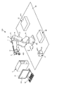
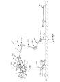
図1は、本発明の第1実施形態に係るロボットシステムを示す概略斜視図である。図2は、図1に示すロボットの概略図である。図3は、図1に示すロボットシステムのブロック図である。
[First Embodiment]
≪Robot system≫
FIG. 1 is a schematic perspective view showing a robot system according to the first embodiment of the present invention. FIG. 2 is a schematic diagram of the robot shown in FIG. FIG. 3 is a block diagram of the robot system shown in FIG.
なお、以下では、説明の都合上、図2中の上側を「上」または「上方」、下側を「下」または「下方」と言う。また、図2中の上下方向を「鉛直方向」とし、その鉛直方向に交差する面を「水平面」とし、水平面に平行な方向を「水平方向」とする。ここで、本願明細書で言う「水平」とは、完全な水平に限定されず、水平に対して5°以下の範囲で傾斜している場合も含む。また、本願明細書で言う「鉛直」とは、完全な鉛直に限定されず、鉛直に対して5°以下の範囲で傾斜している場合も含む。また、図2中に示すロボットの基台側を「基端」、その反対側(ハンド側)を「先端」と言う。 In the following, for convenience of description, the upper side in FIG. 2 is referred to as “upper” or “upper”, and the lower side is referred to as “lower” or “lower”. Further, the vertical direction in FIG. 2 is referred to as “vertical direction”, the plane intersecting with the vertical direction is referred to as “horizontal plane”, and the direction parallel to the horizontal plane is referred to as “horizontal direction”. Here, the term “horizontal” as used in the specification of the present application is not limited to being completely horizontal, and includes a case where the horizontal surface is inclined at an angle of 5° or less. In addition, the term "vertical" as used in the specification of the present application is not limited to the complete vertical, and includes the case where it is inclined within a range of 5° or less with respect to the vertical. Further, the base side of the robot shown in FIG. 2 is called a "base end", and the opposite side (hand side) is called a "tip".
図1に示すロボットシステム100は、例えば、電子部品および電子機器等の対象物の把持、搬送および組立て等の作業で用いられる装置である。
The
図1に示すように、ロボットシステム100は、ロボットアーム10を有するロボット1と、作業領域90内に固定された撮像機能を有する固定カメラ2(撮像部)と、ロボット1に取り付けられた撮像機能を有するモバイルカメラ3(撮像部)と、ロボット1、固定カメラ2およびモバイルカメラ3をそれぞれ制御する制御装置5(校正装置)とを、有する。
As shown in FIG. 1, the
また、本実施形態では、作業領域90内に、対象物の組立てを行う作業台61(組立て台)と、対象物が例えば作業者によって供給される供給台62とが設けられている。作業台61および供給台62は、それぞれ、ロボット1のロボットアーム10の駆動範囲内に設けられている。
Further, in the present embodiment, a work table 61 (assembly table) for assembling an object and a supply table 62 to which the object is supplied by, for example, an operator are provided in the
以下、ロボットシステム100が有する各部を順次説明する。
<ロボット>
図1および図2に示すロボット1は、対象物の把持、搬送および組立て等の作業を行うことができる。
Hereinafter, each part of the
<Robot>
The
ロボット1は、6軸の垂直多関節ロボットであり、基台101と、基台101に接続されたロボットアーム10と、ロボットアーム10の先端部に設けられたハンド102(ツール)と、を有する。また、図3に示すように、ロボット1は、ロボットアーム10を駆動させる動力を発生させる複数の駆動部130および複数のモータードライバー120を備えている。
The
基台101は、ロボット1を作業領域90内の所定の箇所に取り付ける部分である。
ロボットアーム10は、第1アーム11(アーム)と、第2アーム12(アーム)と、第3アーム13(アーム)と、第4アーム14(アーム)と、第5アーム15(アーム)と、第6アーム16(アーム)とを有する。第1アーム11は、基台101に接続されており、第1アーム11と第2アーム12と第3アーム13と第4アーム14と第5アーム15と第6アーム16とは、基端側から先端側に向ってこの順に連結されている。
The
The
図2に示すように、第1アーム11は、基台101に連結された回動軸部材111を有し、回動軸部材111の中心軸を回動中心として基台101に対して回動可能となっている。また、第2アーム12は、第1アーム11に連結された回動軸部材121を有し、回動軸部材121の中心軸を回動中心として第1アーム11に対して回動可能となっている。また、第3アーム13は、第2アーム12に連結された回動軸部材131を有し、回動軸部材131の中心軸を回動中心として第2アーム12に対して回動可能となっている。また、第4アーム14は、第3アーム13に連結された回動軸部材141を有し、回動軸部材141の中心軸を回動中心として第3アーム13に対して回動可能となっている。また、第5アーム15は、第4アーム14に連結された回動軸部材151を有し、回動軸部材151の中心軸を回動中心として第4アーム14に対して回動可能となっている。また、第6アーム16は、第5アーム15に連結された回動軸部材161を有し、回動軸部材161の中心軸A6を回動中心として第5アーム15に対して回動可能となっている。ここで、中心軸A6と第6アーム16の先端面との交わる点(第6アーム16の先端面の中心)を軸座標O6(所定の部位)という。
As shown in FIG. 2, the
ハンド102は、第6アーム16の先端面に取り付けられており、ハンド102の中心軸が第6アーム16の中心軸A6と一致している。ここで、ハンド102の先端面の中心をTCP(ツールセンターポイント)という。本実施形態では、ハンド102が有する2つの指の間の領域の中心をいう。
The
また、各アーム11〜16には、それぞれ、サーボモーター等のモーターおよび減速機を有する複数の駆動部130が設けられている。すなわち、図3に示すように、ロボット1は、各アーム11〜16に対応した数(本実施形態では6つ)の駆動部130を有している。そして、各アーム11〜16は、それぞれ、対応する駆動部130に電気的に接続された複数(本実施形態では6つ)のモータードライバー120を介して制御装置5により制御されている。
Further, each of the
また、各駆動部130には、例えば、エンコーダー、ロータリーエンコーダー等の角度センサー(図示せず)が設けられている。これにより、各駆動部130が有するモーターまたは減速機の回転軸の回転角度を検出することができる。
Further, each
また、図1および図2に示すように、本実施形態では、ロボット1を制御する際に用いられるロボット座標系(ロボット1の座標系)として、水平方向に対してそれぞれ平行なxr軸とyr軸と、水平方向に対して直交し、かつ、鉛直上向きを正方向とするzr軸とによって定まる3次元の直交座標系を設定している。また、xr軸に対する並進成分を「成分xr」とし、yr軸に対する並進成分を「成分yr」とし、zr軸に対する並進成分を「成分zr」とし、zr軸周りの回転成分を「成分ur」とし、yr軸周りの回転成分を「成分vr」とし、xr軸周りの回転成分を「成分wr」とする。成分xr、成分yrおよび成分zrの長さ(大きさ)の単位は「mm」であり、成分ur、成分vrおよび成分wrの角度(大きさ)の単位は「°」である。
Further, as shown in FIGS. 1 and 2, in the present embodiment, as the robot coordinate system (the coordinate system of the robot 1) used when controlling the
<固定カメラ>
図1および図2に示す固定カメラ2は、対象物等を撮像する機能を有する。
<Fixed camera>
The fixed camera 2 shown in FIGS. 1 and 2 has a function of capturing an image of an object or the like.
図2に示すように、固定カメラ2は、複数の画素を有するCCD(Charge Coupled Device)イメージセンサで構成された撮像素子21と、レンズ22(光学系)と、を有している。この固定カメラ2は、対象物等からの光をレンズ22によって撮像素子21の受光面211(センサー面)で結像させ、光を電気信号に変換して、その電気信号を制御装置5へと出力する。ここで、受光面211とは、撮像素子21の表面であって、光が結像する面である。また、本実施形態では、受光面211から光軸OA2方向に焦点距離だけ進んだ位置を「固定カメラ2の撮像基準点O2」とする。
As shown in FIG. 2, the fixed camera 2 has an
このような固定カメラ2は、鉛直方向上方を撮像できるように作業領域90内の所定の箇所に固定されている。また、本実施形態では、固定カメラ2は、その光軸OA2(レンズ22の光軸)が鉛直方向に対してほぼ平行になるように取り付けられている。
Such a fixed camera 2 is fixed at a predetermined position in the
また、本実施形態では、固定カメラ2の画像座標系(固定カメラ2から出力される画像の座標系)として、画像の面内方向に対してそれぞれ平行なxa軸とya軸とよって定まる2次元の直交座標系を設定している。また、xa軸に対する並進成分を「成分xa」とし、ya軸に対する並進成分を「成分ya」とし、xa−ya平面の法線周りの回転成分を「成分ua」とする。成分xaおよび成分yaの長さ(大きさ)の単位は「ピクセル」であり、成分uaの角度(大きさ)の単位は「°」である。 Further, in the present embodiment, the image coordinate system of the fixed camera 2 (the coordinate system of the image output from the fixed camera 2) is two-dimensional determined by the xa axis and the ya axis that are parallel to the in-plane direction of the image. The orthogonal coordinate system of is set. Further, the translational component with respect to the xa axis is referred to as “component xa”, the translational component with respect to the ya axis is referred to as “component ya”, and the rotational component around the normal line of the xa-ya plane is referred to as “component ua”. The unit of length (size) of the components xa and ya is “pixel”, and the unit of angle (size) of the component ua is “°”.
なお、固定カメラ2の画像座標系は、固定カメラ2のカメラ視野に写る3次元直交座標を、レンズ22の光学特性(焦点距離、歪みなど)と撮像素子21の画素数および大きさとを加味して非線形変換した2次元の直交座標系である。
The image coordinate system of the fixed camera 2 takes into account the three-dimensional orthogonal coordinates in the field of view of the fixed camera 2 in consideration of the optical characteristics (focal length, distortion, etc.) of the
<モバイルカメラ>
図1および図2に示すモバイルカメラ3は、対象物等を撮像する機能を有する。
<Mobile camera>
The
図2に示すように、モバイルカメラ3は、複数の画素を有するCCD(Charge Coupled Device)イメージセンサで構成された撮像素子31と、レンズ32(光学系)と、を有する。このモバイルカメラ3は、対象物等からの光をレンズ32によって撮像素子31の受光面311(センサー面)で結像させ、光を電気信号に変換して、その電気信号を制御装置5へと出力する。ここで、受光面311とは、撮像素子31の表面であって、光が結像する面である。また、本実施形態では、受光面311から光軸OA3方向に焦点距離だけ進んだ位置を「モバイルカメラ3の撮像基準点O3」とする。
As shown in FIG. 2, the
このようなモバイルカメラ3は、第6アーム16よりもロボットアーム10の先端側を撮像できるように第6アーム16に取り付けられている。また、本実施形態では、設計上、モバイルカメラ3は、その光軸OA3(レンズ32の光軸)が第6アーム16の中心軸A6に対してほぼ平行になるように、第6アーム16に取り付けられている。また、モバイルカメラ3は、第6アーム16に取り付けられているため、ロボットアーム10の駆動により、第6アーム16と共にその姿勢を変えることができる。
Such a
また、本実施形態では、モバイルカメラ3の画像座標系(モバイルカメラ3で出力される画像の座標系)として、画像の面内方向に対してそれぞれ平行なxb軸とyb軸とによって定まる2次元の直交座標系を設定している。また、xb軸に対する並進成分を「成分xb」とし、yb軸に対する並進成分を「成分yb」とし、xb−yb平面の法線周りの回転成分を「成分ub」とする。成分xbおよび成分ybの長さ(大きさ)の単位は「ピクセル」であり、成分ubの角度(大きさ)の単位は「°」である。 Further, in the present embodiment, the image coordinate system of the mobile camera 3 (the coordinate system of the image output by the mobile camera 3) is two-dimensional determined by the xb axis and the yb axis that are parallel to the in-plane direction of the image. The orthogonal coordinate system of is set. Further, the translation component with respect to the xb axis is referred to as “component xb”, the translation component with respect to the yb axis is referred to as “component yb”, and the rotation component around the normal line of the xb-yb plane is referred to as “component ub”. The unit of the length (size) of the component xb and the component yb is “pixel”, and the unit of the angle (size) of the component ub is “°”.
なお、モバイルカメラ3の画像座標系は、モバイルカメラ3のカメラ視野に写る3次元直交座標を、レンズ32の光学特性(焦点距離、歪みなど)と撮像素子31の画素数および大きさとを加味して非線形変換した2次元の直交座標系である。
The image coordinate system of the
<制御装置>
図1に示す制御装置5は、ロボット1、固定カメラ2およびモバイルカメラ3の各部を制御する。この制御装置5は、例えば、CPU(Central Processing Unit)やROM(read only memory)およびRAM(Random Access Memory)が内蔵されたパーソナルコンピューター(PC)等で構成することができる。
<Control device>
The control device 5 shown in FIG. 1 controls each unit of the
図3に示すように、制御装置5は、駆動制御部51と、情報取得部52と、処理部53と、記憶部54と、を備える。
As shown in FIG. 3, the control device 5 includes a
駆動制御部51は、ロボット1が有する各アーム11〜16の駆動を担う各駆動部130の駆動を制御し、各アーム11〜16をそれぞれ独立して駆動させたり停止させたりすることができる。例えば、駆動制御部51は、ハンド102を目標位置に移動させるために、各アーム11〜16に設けられた各駆動部130が有するモーターの目標値を導出する。また、駆動制御部51は、各駆動部130が有する角度センサーから出力された回転角度(検出結果)を基にロボット1をフィードバック制御する。また、駆動制御部51は、固定カメラ2およびモバイルカメラ3の撮像等を制御したりする。
The
情報取得部52は、ロボット1、固定カメラ2およびモバイルカメラ3からそれぞれ出力される検出結果を取得する。検出結果としては、例えば、ロボット1の各駆動部130が有するモーターまたは減速機の回転軸の回転角度、固定カメラ2およびモバイルカメラ3でそれぞれ撮像した画像、および、ロボット座標系における軸座標O6の座標(成分xr、yr、zr、ur、vr、wr:位置および姿勢)等が挙げられる。
The
処理部53は、情報取得部52で取得した検出結果を基にして各種演算や各種判断等の処理を行う。例えば、処理部53は、固定カメラ2で撮像した画像を基にして固定カメラ2の画像座標系における撮像対象の座標(成分xa、ya、ua:位置および姿勢)を演算したり、モバイルカメラ3で撮像した画像を基にしてモバイルカメラ3の画像座標系における撮像対象の座標(成分xb、yb、ub:位置および姿勢)を演算したりする。また、例えば、処理部53は、固定カメラ2の画像座標系における対象物の座標をロボット座標系における座標に変換するための補正パラメーターを求めたり、モバイルカメラ3の画像座標系における対象物の座標をロボット座標系における座標に変換するための補正パラメーターを求めたりする。
The processing unit 53 performs processing such as various calculations and various determinations based on the detection result acquired by the
記憶部54は、制御装置5が各種処理を行うためのプログラムやデータ等を記憶する。また、記憶部54は、各種検出結果等を記憶する。 The storage unit 54 stores programs and data for the control device 5 to perform various processes. The storage unit 54 also stores various detection results and the like.
また、図1および図3に示すように、制御装置5には、表示機器41および操作機器42が接続されている。
Further, as shown in FIGS. 1 and 3, a
表示機器41は、液晶表示パネル等の表示パネルで構成されたモニター411を有する。作業者は、このモニター411を介して、固定カメラ2およびモバイルカメラ3で撮像した画像やロボット1による作業等を確認したりすることができる。
The
操作機器42は、キーボードで構成された入力デバイスであり、作業者による操作に応じた操作信号を制御装置5に対して出力する。したがって、作業者は、操作機器42を操作することで、制御装置5に対して各種処理等の指示を行うことができる。
以上、ロボットシステム100の基本的な構成について簡単に説明した。
The
The basic configuration of the
このような構成のロボットシステム100では、例えば、以下のような作業を行うことができる。
With the
まず、制御装置5の制御により、ロボットアーム10を駆動させてハンド102で対象物を把持する。その後、ロボットアーム10を駆動させてハンド102を固定カメラ2上に移動させる。次いで、固定カメラ2で対象物を撮像して、その固定カメラ2で撮像した画像を基に、制御装置5は、ハンド102によって対象物を的確に把持しているか否かを判断する。的確に把持していたら、ロボットアーム10の駆動によりハンド102を作業台61上に移動させる。そして、モバイルカメラ3で撮像した画像を基にして、ハンド102で把持している対象物を作業台61上に予め配置されていた対象物に対して組み込む。
First, under the control of the control device 5, the
このような上記作業では、固定カメラ2およびモバイルカメラ3でそれぞれ撮像した対象物の画像を基にして、ロボット1が対象物に対して作業を行う。
In the above work, the
このような作業において、固定カメラ2で撮像した画像を基にロボット1が対象物に対して的確に作業を行うためには、固定カメラ2の画像上の座標(画像座標系における位置および姿勢)をロボット座標系における座標に変換するための補正パラメーターを求める処理、すなわち、固定カメラ2の校正(キャリブレーション)が必要である。また、同様に、モバイルカメラ3で撮像した画像を基にロボット1が対象物等に対して的確に作業を行うためには、モバイルカメラ3の画像上の座標(画像座標系における位置および姿勢)をロボット座標系における座標に変換するための補正パラメーターを求める処理、すなわち、モバイルカメラ3の校正(キャリブレーション)が必要である。
In such work, in order for the
以下、ロボットシステム100を用いた固定カメラ2の校正方法およびモバイルカメラ3の校正方法(以下、これらをまとめて「撮像部の校正方法(キャリブレーション方法)」という)について説明する。
Hereinafter, a method of calibrating the fixed camera 2 and a method of calibrating the
≪撮像部の校正方法(キャリブレーション方法)≫
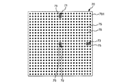
図4は、図1に示すロボットシステムを用いた撮像部の校正方法を示すフローチャートである。図5は、図4に示す撮像部の校正で使用する校正用部材の平面図である。図6は、図4に示す固定カメラの校正を説明するためのロボットの概略図である。図7は、図4に示す固定カメラの校正を説明するためのフローチャートである。図8は、図7に示す基準面を特定する処理を説明するためのフローチャートである。図9は、図8に示す基準面を特定する処理における第1マーカーと第nマーカーとの比較を説明するための図である。図10は、図4に示すモバイルカメラの校正を説明するためのフローチャートである。図11は、図10に示すモバイルカメラの校正を説明するためのロボットの概略図である。図12は、図10に示す基準面を特定する処理を説明するためのフローチャートである。図13は、図10に示すオフセット成分を求める処理を説明するためのフローチャートである。図14は、図13に示すオフセット成分Δu、Δv、Δwを求める処理を説明するための図である。図15、図16、図17、図18および図19は、それぞれ、図13に示すオフセット成分Δx、Δyを求める処理を説明するための図である。図20は、図13に示すオフセット成分Δx、Δyを求める処理を説明するための座標図である。図21は、図13に示すオフセット成分Δzを求める処理を説明するため図である。
<<Calibration method of the imaging unit (calibration method)>>
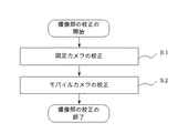
FIG. 4 is a flowchart showing a method of calibrating the image pickup unit using the robot system shown in FIG. FIG. 5 is a plan view of a calibration member used in the calibration of the imaging unit shown in FIG. FIG. 6 is a schematic diagram of a robot for explaining the calibration of the fixed camera shown in FIG. FIG. 7 is a flowchart for explaining the calibration of the fixed camera shown in FIG. FIG. 8 is a flowchart for explaining the process of identifying the reference plane shown in FIG. 7. FIG. 9 is a diagram for explaining the comparison between the first marker and the nth marker in the process of identifying the reference plane shown in FIG. 8. FIG. 10 is a flowchart for explaining the calibration of the mobile camera shown in FIG. FIG. 11 is a schematic diagram of a robot for explaining the calibration of the mobile camera shown in FIG. FIG. 12 is a flowchart for explaining the process of identifying the reference plane shown in FIG. FIG. 13 is a flow chart for explaining the processing for obtaining the offset component shown in FIG. FIG. 14 is a diagram for explaining the process of obtaining the offset components Δu, Δv, Δw shown in FIG. FIG. 15, FIG. 16, FIG. 17, FIG. 18, and FIG. 19 are diagrams for explaining the process of obtaining the offset components Δx and Δy shown in FIG. 13, respectively. FIG. 20 is a coordinate diagram for explaining the process of obtaining the offset components Δx and Δy shown in FIG. FIG. 21 is a diagram for explaining the process of obtaining the offset component Δz shown in FIG.
図4に示すように、本実施形態の撮像部の校正方法では、固定カメラ2の校正(ステップS1)を行った後、モバイルカメラ3の校正(ステップS2)を行う。
As shown in FIG. 4, in the method of calibrating the imaging unit of the present embodiment, after the fixed camera 2 is calibrated (step S1), the
撮像部の校正は、作業者が操作機器42を用いて制御装置5に撮像部の校正開始の指示をすることにより開始される。そして、作業者が制御装置5に撮像部の校正開始の指示さえすれば、それ以降、撮像部の校正は、ロボットシステム100により自動的に行われる。なお、この撮像部の校正は、例えば、ロボット1の作業内容等が変わるごとに行われる。
The calibration of the imaging unit is started by the operator using the
ここで、本実施形態では、図5に示す校正用部材70(キャリブレーションボード)を用いて撮像部の校正を行う。 Here, in the present embodiment, the image capturing unit is calibrated using the calibration member 70 (calibration board) shown in FIG.
校正用部材70は、四角形の平板状の部材であり、校正用部材70の表面701には、複数のマーカー75が付されている。複数のマーカー75は、互いに同じ円形状(形状)であり、互いにほぼ同じ大きさである。また、複数のマーカー75は、隣り合うマーカー75同士のピッチ(間隔)が全てほぼ一定になるように配置されている。また、マーカー75同士のピッチは、予め測定されており、既知である。
The
これら複数のマーカー75のうちの図5中の上側に位置するマーカー75と、図5中の中央部(表面701の中央部)に位置するマーカー75と、図5中の右側に位置するマーカー75には、それぞれ、マーカー75を囲む円がさらに付されている。これら3つのマーカー75とそれを囲む円とで構成された同心円状をなすマーカーのうち、図5中の上側に位置するマーカーを「第1マーカー71(第1基準点)」とし、図5中の中央部に位置するマーカーを「第2マーカー72(第2基準点)」とし、図5中の右側に位置するマーカーを「第3マーカー73(第3基準点)」とする。このような第1マーカー71、第2マーカー72および第3マーカー73は、後述する撮像部の校正の基準面を特定する処理(図7参照)において、基準マーカーとして用いられる。それゆえ、第1マーカー71、第2マーカー72および第3マーカー73は、互いに異なる位置にあり、かつ、第1マーカー71、第2マーカー72および第3マーカー73が同一直線上にない。
Of the plurality of
なお、複数のマーカー75、第1マーカー71、第2マーカー72および第3マーカー73の形状は、それぞれ、図示の形状に限定されず、いかなる形状であってもよい。また、マーカー75、第1マーカー71、第2マーカー72および第3マーカー73は、それぞれ、視認できる形態であればよく、いかなる色であってもよいし、凹凸を有する形態であってもよい。また、複数のマーカー75、第1マーカー71、第2マーカー72および第3マーカーは、異なる形態あってもよい。例えば、複数のマーカー75、第1マーカー71、第2マーカー72および第3マーカー73は、それぞれ異なる色や形であってもよい。ただし、第1マーカー71、第2マーカー72および第3マーカー73は、基準マーカーとして用いるため、他のマーカー75との識別力を有する形態であることが好ましい。
The shapes of the plurality of
このような構成の校正用部材70は、図6に示すように、作業者による撮像部の校正開始の指示をする前に、予め、ロボット1にハンド102で把持させておく。また、本実施形態では、第2マーカー72が第6アーム16の中心軸A6上に位置するように、ハンド102によって校正用部材70を把持させる。また、本実施形態では、ロボット座標系における軸座標O6の座標に対する第2マーカー72の座標が特定されており、ロボット座標系における第2マーカー72の座標を求めることができるようになっている。
As shown in FIG. 6, the
なお、本実施形態では、前述したように、第2マーカー72が第6アーム16の中心軸A6上に位置しているが、ロボット座標系における第2マーカー72の座標を求めることができるよう設定されていれば、第2マーカー72が第6アーム16の中心軸A6上に位置していなくてもよい。
In the present embodiment, as described above, the
<固定カメラの校正(ステップS1)>
図4に示すように、作業者による撮像部の校正の開始の指示がなされると、制御装置5は、まず、固定カメラ2の校正(ステップS1)を開始する。
<Calibration of fixed camera (step S1)>
As shown in FIG. 4, when the operator gives an instruction to start the calibration of the imaging unit, the control device 5 first starts the calibration of the fixed camera 2 (step S1).
図7に示すように、固定カメラ2の校正(ステップS1)では、基準面を特定する処理(ステップS11)を行った後、固定カメラ2の画像座標系とロボット座標系との関係を求める処理(ステップS12)を行う。 As shown in FIG. 7, in the calibration of the fixed camera 2 (step S1), after performing the process of identifying the reference plane (step S11), the process of obtaining the relationship between the image coordinate system of the fixed camera 2 and the robot coordinate system. (Step S12) is performed.
[基準面を特定する処理(ステップS11)]
以下、基準面を特定する処理(ステップS11)を、図8に示すフローチャートを参照しつつ説明する。
[Process for Specifying Reference Surface (Step S11)]
Hereinafter, the process of identifying the reference plane (step S11) will be described with reference to the flowchart shown in FIG.
図8に示すように、基準面を特定する処理(ステップS11)が開始すると、まず、制御装置5は、ロボットアーム10を駆動させて、図6に示すように、校正用部材70を固定カメラ2に対向させる(ステップS111)。
As shown in FIG. 8, when the process of identifying the reference plane (step S11) is started, first, the control device 5 drives the
次いで、図8に示すように、制御装置5は、ロボットアーム10を駆動させて、校正用部材70に付された第2マーカー72が固定カメラ2の画像の中心部に位置するように校正用部材70を移動させる(ステップS112)。
Next, as shown in FIG. 8, the control device 5 drives the
次いで、制御装置5は、固定カメラ2に第2マーカー72を撮像させる(ステップS113)。このとき、制御装置5は、固定カメラ2の焦点が第2マーカー72に合う(合焦する)ように、ロボットアーム10を駆動させることにより、校正用部材70を移動させる処理(合焦処理)を行う。なお、この合焦処理は省略しても構わない。
Next, the control device 5 causes the fixed camera 2 to capture an image of the second marker 72 (step S113). At this time, the control device 5 moves the
次いで、制御装置5は、固定カメラ2で撮像した第2マーカー72の画像を「第1画像」として記憶部54に記憶し、かつ、第1画像を撮像した際のロボット座標系における軸座標O6の座標を記憶部54に記憶する(ステップS114)。ここで、固定カメラ2における基準面を特定する処理(ステップS11)では、第1画像を撮像した際の第2マーカー72を「第1基準マーカー」とする。
Next, the control device 5 stores the image of the
次に、制御装置5は、ロボットアーム10を駆動させて、固定カメラ2の画像上においてステップS112で移動させた位置とは異なる位置に第2マーカー72が位置するように、校正用部材70をロボット座標系におけるxr軸、yr軸およびzr軸に沿って並進移動させる(ステップS115)。
Next, the control device 5 drives the
次いで、制御装置5は、固定カメラ2に第2マーカー72を撮像させる(ステップS116)。 Next, the control device 5 causes the fixed camera 2 to capture an image of the second marker 72 (step S116).
次いで、ステップS116において固定カメラ2で撮像した画像における第2マーカー72の形状および大きさと、ステップS114で記憶部54に記憶した第1画像における第2マーカー72の形状および大きさとを比較する(ステップS117)。そして、第2マーカー72の形状および大きさと、第1画像における第2マーカー72の形状および大きさとの差が、所定の閾値内であるか否かを判断する(ステップS118)。
Next, the shape and size of the
所定の閾値内であると判断した場合(ステップS118の「Yes」)には、ステップS1110に移行する。一方、所定の閾値内でないと判断した場合(ステップS118の「No」)には、所定の閾値内になるようにロボットアーム10の駆動により校正用部材70を移動させる(ステップS119)。例えば、図9に示すように、図9中の2点鎖線で示す第2マーカー72の大きさ(外形)が、図9中の実線で示す第1画像における第2マーカー72の大きさ(外形)と異なり、その大きさの差が所定の閾値内でない場合には、所定の閾値内になるようにロボットアーム10の駆動により校正用部材70を移動させる。
If it is determined that it is within the predetermined threshold value (“Yes” in step S118), the process proceeds to step S1110. On the other hand, when it is determined that the value is not within the predetermined threshold value (“No” in step S118), the
次に、制御装置5は、所定の閾値内であると判断したら、固定カメラ2で撮像した第2マーカー72の画像を「第2画像(第n画像)」として記憶部54に記憶し、かつ、第2画像(第n画像)を撮像した際のロボット座標系における軸座標O6の座標を記憶部54に記憶する(ステップS1110)。ここで、固定カメラ2における基準面を特定する処理(ステップS11)では、第2画像を撮像した際の第2マーカー72を「第2基準マーカー」とする。なお、第2画像を撮像する際には、ハンド102に把持されている校正用部材70に付された第2マーカー72は、第1画像を撮像する際における位置と異なる位置にある。
Next, when the control device 5 determines that it is within the predetermined threshold value, it stores the image of the
次に、撮像した画像の数nが予め設定した所定数(ただし、nは整数であって、3≦nの関係を満足する数)であるか否かを判断する(ステップS1111)。所定数であると判断した場合には、ステップS1112に移行し、所定数未満であると判断した場合には、所定数であると判断されるまで、前述したステップS115からステップS1110を繰り返す。
Next, it is determined whether or not the number n of captured images is a preset predetermined number (where n is an integer and satisfies the
ここで、本実施形態では、画像の数が3になるまで画像を取得すること、すなわち、固定カメラ2で3つの画像(第1画像、第2画像および第3画像)を撮像することを予め設定している。そのため、本実施形態では、固定カメラ2で第2画像を撮像した後に、さらにもう1回、ステップS115からステップS1110を行い、ロボットアーム10の駆動により校正用部材70を移動させて固定カメラ2で撮像した第2マーカー72の画像を「第3画像」として記憶部54に記憶し、かつ、第3画像を撮像した際のロボット座標系における軸座標O6の座標を記憶部54に記憶する。ここで、固定カメラ2における基準面を特定する処理(ステップS11)では、第3画像を撮像した際の第2マーカー72を「第3基準マーカー」とする。なお、第3画像を撮像する際には、ハンド102に把持されている校正用部材70に付された第2マーカー72は、第1画像を撮像する際における位置および第2画像を撮像する際における位置と異なる位置にあり、それらは同一直線上にない。また、固定カメラ2における基準面を特定する処理(ステップS11)では、第2マーカー72が「第1基準マーカー、第2基準マーカーおよび第3基準マーカー」を兼ねていると捉えることができる。
Here, in the present embodiment, acquisition of images until the number of images becomes three, that is, capturing of three images (first image, second image, and third image) by the fixed camera 2 is performed in advance. It is set. Therefore, in the present embodiment, after the second image is captured by the fixed camera 2, the steps S115 to S1110 are performed once again, and the
次に、画像の数nが所定数であると判断したら、処理部53は、記憶部54に記憶したn個(本実施形態では3つ)のロボット座標系における軸座標O6の座標を基に、図6に示すような撮像素子21(3つの異なる箇所に配置された状態の第2マーカー72を通る平面)に平行な基準面81の原点およびx軸、y軸、z軸の各方向を求める(ステップS1112)。そして、制御装置5は、ロボット座標系における基準面81の位置および姿勢、すなわち、基準面81の成分xr、yr、zr、ur、vr、wrを定義する(ステップS1113)。
以上にて、図7に示す基準面を特定する処理(ステップS11)が終了する。
Next, when it is determined that the number n of images is the predetermined number, the processing unit 53 uses the coordinates of the axis coordinates O6 in the n (three in the present embodiment) robot coordinate system stored in the storage unit 54. , The origin of the reference plane 81 parallel to the image sensor 21 (the plane passing through the
This is the end of the process (step S11) for identifying the reference plane shown in FIG. 7.
以上のように、制御装置5によれば、固定カメラ2(撮像部)で撮像した画像(第1画像、第2画像および第3画像)を基にして基準面81の姿勢を求めることができる。このため、従来のように、作業者によるタッチアップ用ハンドとキャリブレーション治具(校正用部材)との接触を判断する作業を省くことができる。このため、人為的な誤差や、作業者によるバラツキを低減することができ、よって、基準面81の姿勢を高精度に求めることができる。また、従来のようにタッチアップ用ハンドをキャリブレーション治具に接触させることにより基準面を求めると、キャリブレーション治具の材質等によって求めた基準面の姿勢が異なり、基準面の姿勢を高精度に検出することが難しい。これに対し、本実施形態では、固定カメラ2で撮像した画像を基にして基準面81の姿勢を求めているので、校正用部材70に対して接触せずに(非接触で)、基準面81の姿勢を求めることができる。このため、例えば校正用部材70の材質等によらず基準面81の姿勢を高精度に求めることができる。
As described above, according to the control device 5, the attitude of the reference plane 81 can be obtained based on the images (first image, second image, and third image) captured by the fixed camera 2 (imaging unit). .. Therefore, it is possible to omit the work of determining the contact between the touch-up hand and the calibration jig (calibration member), which is required by the worker, as in the conventional case. For this reason, it is possible to reduce human error and variation due to the operator, and therefore, the posture of the reference surface 81 can be obtained with high accuracy. Also, if the reference plane is obtained by contacting the touch-up hand with the calibration jig as in the conventional case, the obtained posture of the reference plane differs depending on the material of the calibration jig, etc. Difficult to detect. On the other hand, in the present embodiment, since the attitude of the reference surface 81 is obtained based on the image captured by the fixed camera 2, the reference surface 81 is not contacted (without contact) with the
また、制御装置5によれば、固定カメラ2で撮像した画像を基にして基準面81の姿勢を求めることができるため、従来よりも基準面81の姿勢を容易かつ迅速に求めることができる。 Further, according to the control device 5, the attitude of the reference plane 81 can be obtained based on the image captured by the fixed camera 2, so that the attitude of the reference plane 81 can be obtained more easily and quickly than in the conventional case.
また、前述したように、本実施形態では、3つの画像(第1画像、第2画像および第3画像)をそれぞれ撮像した際のロボット座標系における軸座標O6(所定の部位)の座標を基にして基準面81を求めている。したがって、基準面81は軸座標O6を含む面であるといえる。そのため、基準面81でロボット1が作業(例えば、ハンド102により対象物を的確に把持しているか否かを判断する作業)を行うことで、ロボット1は前記作業を的確に行うことができる。
Further, as described above, in the present embodiment, the coordinates of the axis coordinate O6 (predetermined part) in the robot coordinate system when the three images (the first image, the second image, and the third image) are captured are based on the coordinates. Then, the reference plane 81 is obtained. Therefore, it can be said that the reference plane 81 is a plane including the axis coordinate O6. Therefore, when the
特に、前述したように、本実施形態では、3つの画像を撮像する際に、合焦処理をしておくことで、ロボット1が基準面81で対象物の検出、検査、組み立て等の各作業を行えば、ロボット1は各種作業をより高い精度で行うことができる。
In particular, as described above, in the present embodiment, when the three images are captured, the focusing process is performed so that the
なお、予め、軸座標O6とツールセンターポイントTCPとの間の距離が既知であれば、その距離と、軸座標O6を含む面である基準面81とを基にして、ツールセンターポイントTCPを含む面を求めることができる。 If the distance between the axis coordinate O6 and the tool center point TCP is known in advance, the tool center point TCP is included based on the distance and the reference plane 81 that is the plane including the axis coordinate O6. You can ask for a face.
また、本実施形態では、軸座標O6の座標を基にして基準面81を特定する処理(ステップS11)を行ったが、ツールセンターポイントTCPの座標を基に基準面81を特定してもよいし、その他のロボットの任意の部位を基に基準面81を特定してもよい。 Further, in the present embodiment, the process of identifying the reference plane 81 based on the coordinate of the axis coordinate O6 (step S11) is performed, but the reference plane 81 may be identified based on the coordinate of the tool center point TCP. However, the reference plane 81 may be specified based on any other part of the robot.
また、前述したように、本実施形態では、第1画像における第2マーカー72の大きさと、第2画像における第2マーカー72の大きさと、第3画像における第2マーカー72の大きさとに基づいて、基準面81の位置および姿勢を求めている。そのため、本実施形態では、各画像における第2マーカー72の大きさに基づいて基準面81の位置および姿勢を求めれば、基準面81の姿勢を的確に求めることができる。
Further, as described above, in the present embodiment, based on the size of the
また、各画像における第2マーカー72の大きさに基づいて基準面81の位置および姿勢を求めることは、第1画像を取得した際の第2マーカー72と固定カメラ2の受光面211(より具体的には、撮像基準点O2)との間の距離(第1距離)と、第2画像を取得した際の第2マーカー72と受光面211(撮像基準点O2)との間の距離(第2距離)と、第3画像を取得した際の第2マーカー72と受光面211(撮像基準点O2)との間の距離(第3距離)とに基づいて、基準面81の姿勢を求めていることと同等である。したがって、本実施形態の校正方法によれば、第1距離、第2距離および第3距離の距離に基づいて、基準面81の姿勢を求めることができる。
In addition, determining the position and orientation of the reference plane 81 based on the size of the
[固定カメラの画像座標系とロボット座標系との関係を求める処理(ステップS12)]
次に、図7に示すように、固定カメラの画像座標系とロボット座標系との関係を求める処理(ステップS12)を行う。
[Process for Obtaining Relationship between Fixed Camera Image Coordinate System and Robot Coordinate System (Step S12)]
Next, as shown in FIG. 7, processing for obtaining the relationship between the image coordinate system of the fixed camera and the robot coordinate system (step S12) is performed.
制御装置5は、まず、ロボットアーム10を駆動させて、前述したステップS12で求めた基準面81内の格子状に配列された任意の9つの基準点(仮想の目標点)にそれぞれ軸座標O6が位置するように、校正用部材70を移動させる。すなわち、第2マーカー72を格子状に配列された9つの箇所に移動させる。このとき、制御装置5は、校正用部材70を移動させるごとに、固定カメラ2に第2マーカー72を撮像させる。
The control device 5 first drives the
ここで、9つの基準点は、全て固定カメラ2の画像の範囲内(撮像領域内)にあり、隣り合う基準点同士の間隔が全て等しくなっているものとする。 Here, it is assumed that all nine reference points are within the range of the image of the fixed camera 2 (within the imaging area), and the intervals between adjacent reference points are all equal.
次に、制御装置5は、9つの画像に基づいた固定カメラ2の画像座標系における第2マーカー72の座標(成分xa、ya、ua)と、前述したステップS11で求めたロボット座標系における基準面81の座標(成分xr、yr、ur)とに基づいて、固定カメラ2の画像座標をロボット座標系における基準面81の座標に変換する補正パラメーター(座標変換行列)を求める。
Next, the control device 5 controls the coordinates (components xa, ya, ua) of the
このようにして求めた補正パラメーターを用いれば、固定カメラ2で撮像した対象物等の位置および姿勢(具体的には、成分xa、ya、ua)をロボット座標系における値(具体的には、成分xr、yr、ur)に変換することができる。なお、この補正パラメーターは、レンズ22の歪み等の固定カメラ2の内部パラメーターも加味した値である。
By using the correction parameters thus obtained, the position and orientation (specifically, the components xa, ya, and ua) of the object or the like imaged by the fixed camera 2 can be calculated as values in the robot coordinate system (specifically, Components xr, yr, ur). It should be noted that this correction parameter is a value that also takes into consideration internal parameters of the fixed camera 2 such as distortion of the
なお、本実施形態では、前述したように、9つの基準点を用いて補正パラメーターを求めたが、補正パラメーターを求めるために用いる基準点の数が多いほど校正の精度は高くなる。
以上にて、図4に示す固定カメラの校正(ステップS1)が終了する。
In this embodiment, as described above, the correction parameter is obtained using nine reference points, but the accuracy of the calibration increases as the number of reference points used to obtain the correction parameter increases.
This completes the calibration (step S1) of the fixed camera shown in FIG.
<モバイルカメラの校正(ステップS2)>
次に、制御装置5は、図4に示すモバイルカメラ3の校正(ステップS2)を開始する。
<Calibration of mobile camera (step S2)>
Next, the control device 5 starts the calibration (step S2) of the
図10に示すように、モバイルカメラ3の校正(ステップS2)では、基準面を特定する処理(ステップS21)、オフセット成分を求める処理(ステップS22)、作業面を特定する処理(ステップS23)、ロボット1にマーカーの位置および姿勢を教示する処理(ステップS24)、および、モバイルカメラ3の画像座標系とロボット座標系との関係を求める処理(ステップS25)を、この順に行う。
As shown in FIG. 10, in the calibration of the mobile camera 3 (step S2), a process of identifying a reference plane (step S21), a process of obtaining an offset component (step S22), a process of identifying a work surface (step S23), The process of teaching the position and orientation of the marker to the robot 1 (step S24) and the process of obtaining the relationship between the image coordinate system of the
[基準面を特定する処理(ステップS21)]
まず、図11に示すように、基準面を特定する処理(ステップS21)を行う前に、予め、ハンド102で把持していた校正用部材70を作業台61の作業面611上に載置しておく。その後、基準面を特定する処理(ステップS21)を行う。
[Process for Specifying Reference Surface (Step S21)]
First, as shown in FIG. 11, the
以下、基準面を特定する処理(ステップS21)を、図12に示すフローチャートを参照しつつ、その詳細を説明する。 Hereinafter, the details of the process (step S21) of identifying the reference plane will be described with reference to the flowchart shown in FIG.
図12に示すように、基準面を特定する処理(ステップS21)が開始すると、まず、制御装置5は、ロボットアーム10を駆動させて、図12に示すように、モバイルカメラ3を校正用部材70に対向させる(ステップS211)。
As shown in FIG. 12, when the process of identifying the reference plane (step S21) is started, first, the control device 5 drives the
次いで、制御装置5は、ロボットアーム10を駆動させて、校正用部材70に付された第1マーカー71がモバイルカメラ3の画像の中心部に位置するようにモバイルカメラ3を移動させる(ステップS212)。
Next, the control device 5 drives the
次いで、制御装置5は、モバイルカメラ3に第1マーカー71を撮像させる(ステップS213)。このとき、制御装置5は、モバイルカメラ3の焦点が第1マーカー71に合う(合焦する)ようにロボットアーム10を駆動させることにより、モバイルカメラ3を移動させる処理(合焦処理)を行う。なお、この合焦処理は省略しても構わない。
Next, the control device 5 causes the
次いで、制御装置5は、モバイルカメラ3で撮像した第1マーカー71の画像を「第1画像」として記憶部54に記憶し、かつ、第1画像を撮像した際のロボット座標系における軸座標O6の座標を記憶部54に記憶する(ステップS214)。ここで、モバイルカメラ3における基準面を特定する処理(ステップS21)では、第1マーカー71を「第1基準マーカー」とする。
Next, the control device 5 stores the image of the first marker 71 captured by the
次に、制御装置5は、ロボットアーム10を駆動させて、第2マーカー72がモバイルカメラ3の画像の中心部に位置するようにモバイルカメラ3を並進移動させる(ステップS215)。
Next, the control device 5 drives the
次いで、制御装置5は、モバイルカメラ3に第2マーカー72(第nマーカー)を撮像させる(ステップS216)。
Next, the control device 5 causes the
次いで、ステップS216においてモバイルカメラ3で撮像した画像における第2マーカー72の形状および大きさと、ステップS214で記憶部54に記憶した第1画像における第1マーカー71の形状および大きさとを比較する(ステップS217)。そして、第2マーカー72の形状および大きさと、第1マーカー71の形状および大きさとの差が、所定の閾値内であるか否かを判断する(ステップS218)。
Next, the shape and size of the
所定の閾値内であると判断した場合(ステップS218の「Yes」)には、ステップS2110に移行する。一方、所定の閾値内でないと判断した場合(ステップS218の「No」)には、所定の閾値内になるようにロボットアーム10の駆動によりモバイルカメラ3を移動させる(ステップS219)。
If it is determined that it is within the predetermined threshold value (“Yes” in step S218), the process proceeds to step S2110. On the other hand, if it is determined that the value is not within the predetermined threshold value (“No” in step S218), the
次に、制御装置5は、所定の閾値内であると判断したら、モバイルカメラ3で撮像した第2マーカー72(第nマーカー)の画像を「第2画像(第n画像)」として記憶部54に記憶し、かつ、第2画像(第n画像)を撮像した際のロボット座標系における軸座標O6の座標を記憶部54に記憶する(ステップS2110)。ここで、モバイルカメラ3における基準面を特定する処理(ステップS21)では、第2マーカー72を「第2基準マーカー」とする。
Next, when the control device 5 determines that it is within the predetermined threshold value, the image of the second marker 72 (nth marker) captured by the
次に、撮像した画像の数nが予め設定した所定数(ただし、nは整数であって、3≦nの関係を満足する数)であるか否かを判断する(ステップS2111)。所定数であると判断した場合には、ステップS2112に移行し、所定数未満であると判断した場合には、所定数であると判断されるまで、前述したステップS215からステップS2110を繰り返す。 Next, it is determined whether or not the number n of picked-up images is a preset predetermined number (where n is an integer and satisfies the relationship of 3≦n) (step S2111). If it is determined that the number is the predetermined number, the process proceeds to step S2112, and if it is determined that the number is less than the predetermined number, steps S215 to S2110 described above are repeated until it is determined that the number is the predetermined number.
ここで、本実施形態では、モバイルカメラ3で3つの画像(第1画像、第2画像および第3画像)を撮像することを予め設定している。そのため、本実施形態では、モバイルカメラ3で第2画像を撮像した後に、さらにもう1回、ステップS215からステップS2110を行い、モバイルカメラ3で撮像した第3マーカー73の画像を「第3画像」として記憶部54に記憶し、かつ、第3画像を撮像した際のロボット座標系における軸座標O6の座標を記憶部54に記憶する。ここで、モバイルカメラ3における基準面を特定する処理(ステップS21)では、第3マーカー73を「第3基準マーカー」とする。
Here, in the present embodiment, it is preset that the
次に、画像の数nが所定数であると判断したら、処理部53は、記憶部54に記憶したn個(本実施形態では3つ)のロボット座標系における軸座標O6の座標を基に、図11に示すような表面701(第1マーカー71、第2マーカー72および第3マーカー73を通る平面)に平行な基準面82の原点およびx軸、y軸、z軸の各方向を求める(ステップS2112)。そして、制御装置5は、ロボット座標系における基準面82の位置および姿勢、すなわち、基準面82の成分xr、yr、zr、ur、vr、wrを定義する(ステップS2113)。
Next, when it is determined that the number n of images is the predetermined number, the processing unit 53 uses the coordinates of the axis coordinates O6 in the n (three in the present embodiment) robot coordinate system stored in the storage unit 54. , The origin of the
以上のように、制御装置5によれば、固定カメラ2における基準面を特定する処理(ステップS11)と同様の効果を発揮することができる。すなわち、モバイルカメラ3(撮像部)で撮像した画像(第1画像、第2画像および第3画像)を用いているため、校正用部材70に対して接触せずに、基準面82の姿勢を求めることができ、よって、例えば校正用部材70の材質等によらず基準面82の姿勢を高精度に求めることができる。また、従来よりも基準面82の姿勢を容易かつ迅速に求めることができる。
As described above, according to the control device 5, the same effect as the process (step S11) of identifying the reference plane in the fixed camera 2 can be exhibited. That is, since the images (the first image, the second image, and the third image) captured by the mobile camera 3 (imaging unit) are used, the posture of the
また、前述したように、本実施形態では、第1画像における第1マーカー71の大きさと、第2画像における第2マーカー72の大きさと、第3画像における第2マーカー72の大きさとに基づいて、基準面82の位置および姿勢を求めている。そのため、本実施形態では、各画像における第2マーカー72の大きさに基づいて基準面82の位置および姿勢を求めれば、基準面82の姿勢を的確に求めることができる。
Further, as described above, in the present embodiment, based on the size of the first marker 71 in the first image, the size of the
また、各画像における第2マーカー72の大きさに基づいて基準面82の位置および姿勢を求めることは、第1画像を取得した際の第1マーカー71とモバイルカメラ3の受光面311(より具体的には、撮像基準点O3)との間の距離(第1距離)と、第2画像を取得した際の第2マーカー72と受光面311(撮像基準点O3)との間の距離(第2距離)と、第3画像を取得した際の第3マーカー73と受光面311(撮像基準点O3)との間の距離(第3距離)とに基づいて、基準面82の姿勢を求めていることと同等である。したがって、本実施形態の校正方法によれば、第1距離、第2距離および第3距離の距離に基づいて、基準面82の姿勢を求めることができる。
In addition, determining the position and orientation of the
さらに、上述したように、モバイルカメラ3における基準面を特定する処理(ステップS21)では、大きさが互いに等しい第1マーカー71、第2マーカー72および第3マーカー73が付された校正用部材70を用いて、画像上における第1マーカー71、第2マーカー72および第3マーカー73の大きさが互いに等しくなるように固定カメラ2で第1画像、第2画像および第3画像を撮像している。このように撮像すれば、モバイルカメラ3の焦点距離や画角が既知でなくとも、表面701に平行な(モバイルカメラ3の光軸OA3に対して直交している)基準面82を求めることができる。
Further, as described above, in the process of identifying the reference plane in the mobile camera 3 (step S21), the
また、第1マーカー71、第2マーカー72および第3マーカー73の大きさが互いに等しくなるようにモバイルカメラ3で第1画像、第2画像および第3画像を撮像することは、互いに距離が等しい第1距離、第2距離および第3距離に基づいて、基準面82の姿勢を求めていることと同等である。したがって、本実施形態の校正方法によれば、距離が等しい第1距離、第2距離および第3距離に基づいて、モバイルカメラ3の焦点距離や画角が既知でなくとも、表面701に平行な基準面82を容易かつ迅速に求めることができる。
In addition, capturing the first image, the second image, and the third image with the
なお、本実施形態では、第1マーカー71、第2マーカー72および第3マーカー73のそれぞれの大きさが互いに等しいが、これらの大きさの関係が既知であれば、これらの大きさはそれぞれ異なっていてもよい。その場合には、第1マーカー71、第2マーカー72および第3マーカー73のそれぞれの大きさの関係に基づいて、第1距離、第2距離および第3距離の距離を求めることで、表面701に平行な基準面82を容易かつ迅速に求めることができる。
In the present embodiment, the sizes of the first marker 71, the
[オフセット成分を求める処理(ステップS22)]
次に、オフセット成分を求める処理(ステップS22)を、図13に示すフローチャートを参照しつつ説明する。
[Process for Obtaining Offset Component (Step S22)]
Next, the process of obtaining the offset component (step S22) will be described with reference to the flowchart shown in FIG.
ここで、前述したように、モバイルカメラ3は、設計上、光軸OA3が第6アーム16の中心軸A6に対してほぼ平行になるように、第6アーム16に対してオフセットして取り付けられている。しかし、実際には、その設計上のオフセット成分(第6アーム16に対するモバイルカメラ3の位置および姿勢)からズレが生じる。このズレは、例えば、モバイルカメラ3の組み付け誤差や、モバイルカメラ3の筐体に対する撮像素子31の組み付け誤差等により生じる。
Here, as described above, the
そこで、このオフセット成分を求める処理(ステップS22)にて、実際のオフセット成分(第6アーム16に対するモバイルカメラ3の位置および姿勢)を求める。
Therefore, in the process of obtaining this offset component (step S22), the actual offset component (position and orientation of the
以下のオフセット成分を求める処理(ステップS22)では、回動軸部材161の軸座標O6に対するモバイルカメラ3の撮像基準点O3の位置および光軸OA3の方向(姿勢)のオフセット成分(Δx、Δx、Δy、Δu、Δv、Δw)を求める。
In the following process of obtaining an offset component (step S22), the offset component (Δx, Δx, Δx, Δx,) of the position of the imaging reference point O3 of the
なお、本実施系形態では、軸座標O6に対する撮像基準点O3の位置および光軸OA3の方向のオフセット成分を求めるが、オフセット成分を求めるにあたり基準とする箇所は、軸座標O6および撮像基準点O3に限定されず任意である。 In the present embodiment, the position of the image pickup reference point O3 with respect to the axis coordinate O6 and the offset component in the direction of the optical axis OA3 are obtained. The reference point for obtaining the offset component is the axis coordinate O6 and the image pickup reference point O3. It is not limited to and is arbitrary.
図13に示すように、オフセットを求める処理(ステップS22)が開始すると、まず、制御装置5は、ロボットアーム10を駆動させて、モバイルカメラ3に校正用部材70を検出させる(ステップS221)。
As shown in FIG. 13, when the process for obtaining the offset (step S22) is started, the control device 5 first drives the
次に、制御装置5は、モバイルカメラ3の受光面311が校正用部材70の表面701に正対するようにロボットアーム10を駆動させる(ステップS222)。
Next, the control device 5 drives the
次いで、制御装置5は、モバイルカメラ3の受光面311に対する校正用部材70の表面701の平行度を検証する(ステップS223)。そして、制御装置5は、平行度が所定の閾値内であるか否かを判断する(ステップS224)。
Next, the control device 5 verifies the parallelism of the
図14に示すように、平行度は、画像における表面701に付された隣り合うマーカー75同士のピッチPの差を用いて検証する。例えば、図14中の実線で示すように、隣り合うマーカー75同士のピッチP1、P2、P3、P4の差がほぼ同じであり、その差が所定の閾値内である場合には、ステップS225に移行する。一方、図14中の2点鎖線で示すように、隣り合うマーカー75同士のピッチP1’、P2’、P3’、P4’の差が異なり、その差が所定の閾値を超える場合には、所定の閾値内になるまで、ステップS221からステップS224を繰り返す。ここで、所定の閾値内であることは、前述した基準面82と光軸OA3とが閾値以内で垂直になっていることを意味する。
As shown in FIG. 14, the parallelism is verified by using the difference in pitch P between the
次に、制御装置5は、所定の閾値内であると判断したら、所定の閾値内であると判断した際のロボット座標系における軸座標O6の成分ur、vr、wrと、前述した基準面を特定する処理(ステップS21)で求めた際のロボット座標系における基準面82の成分ur、vr、wrとの差からオフセット成分Δu、Δv、Δwを求める(ステップS225)。このオフセット成分Δu、Δv、Δwは、軸座標O6に対する光軸OA3のオフセット成分Δu、Δv、Δに相当する。
Next, if the control device 5 determines that it is within the predetermined threshold value, it determines the components ur, vr, and wr of the axis coordinate O6 in the robot coordinate system at the time of determining that it is within the predetermined threshold value and the above-described reference plane. Offset components Δu, Δv, Δw are obtained from the differences between the components ur, vr, wr of the
次に、図13に示すように、制御装置5は、軸座標O6に対する撮像基準点O3のオフセット成分Δx、Δyを求める(ステップS226)。以下、オフセット成分Δx、Δyを求める方法を図15〜図20を参照しつつ説明する。なお、図15〜図19は、例えば、ロボット1を鉛直方向上方から見たときのモバイルカメラ3および第6アーム16を模式的に示している。
Next, as shown in FIG. 13, the control device 5 obtains the offset components Δx and Δy of the imaging reference point O3 with respect to the axis coordinates O6 (step S226). Hereinafter, a method of obtaining the offset components Δx and Δy will be described with reference to FIGS. 15 to 19 schematically show, for example, the
具体的には、まず、図15に示すように、制御装置5は、例えばモバイルカメラ3の画像30の中心O30(重心)に第2マーカー72が位置するようにロボットアーム10を駆動させる。この図15に示すモバイルカメラ3および第6アーム16の状態を「第1状態」とする。ここで、画像30の中心O30と撮像基準点O3は一致している。
Specifically, first, as shown in FIG. 15, the control device 5 drives the
次いで、図16に示すように、制御装置5は、ロボットアーム10を駆動させて第6アーム16を中心軸A6周りに所定の角度で回動させる。この際の所定の角度は、画像30外に第2マーカー72が出ない範囲内(モバイルカメラ3の撮像領域内に収まる範囲内)の所定の角度(例えば1〜10°程度)とする。この図16に示すモバイルカメラ3および第6アーム16の状態を「第2状態」とする。
Next, as shown in FIG. 16, the control device 5 drives the
次いで、図17に示すように、制御装置5は、ロボットアーム10を駆動させて、第2マーカー72が中心O30に一致するようにモバイルカメラ3および第6アーム16をロボット座標系におけるxr軸およびyr軸を含む平面(基準面82のx−y平面)に平行な平面内に並進移動させる。この図17に示すモバイルカメラ3および第6アーム16の状態を「第3状態」とする。
Next, as shown in FIG. 17, the control device 5 drives the
このような第1状態から第2状態を経て第3状態となるモバイルカメラ3および第6アーム16の移動は、図15に示す第1状態と図17に示す第3状態とを見ると、撮像中心O30(撮像基準点O3)を通る線分を回動中心軸にして軸座標O6(第6アーム16)が回動していることと同等であることが分かる。したがって、図20に示すように、第1状態から第2状態を経て第3状態となる移動は、中心O30(撮像基準点O3)を通る線分を回動中心軸として軸座標O6を回動角度θ10で移動させたことと等しい。それゆえ、回動角度θ10と、第1状態でのロボット座標系における軸座標O6の座標と、第3状態でのロボット座標系における軸座標O6の座標とに基づいて、ロボット座標系における撮像基準点O3の座標を求める。そして、求めたロボット座標系における撮像基準点O3の座標と、第1状態および第3状態のいずれか一方のロボット座標系における軸座標O6の座標とから、軸座標O6に対する撮像基準点O3の仮オフセット成分Δx’、Δy’を求める。
The movement of the
次いで、図18に示すように、制御装置5は、第2マーカー72が画像30外に出ないように仮オフセット成分Δx’、Δy’を基にしてロボットアーム10を駆動させ、撮像基準点O3(中心O30)を通る線分を回動中心軸として軸座標O6を所定の角度で回動させる。この図18に示すモバイルカメラ3および第6アーム16の状態を「第4状態」とする。
Next, as shown in FIG. 18, the control device 5 drives the
次に、図19に示すように、制御装置5は、ロボットアーム10の駆動によりモバイルカメラ3および第6アーム16をロボット座標系におけるxr軸およびyr軸を含む平面(基準面82のx−y平面)に平行な平面内に並進移動させ、画像30の中心O30に第2マーカー72を位置させる。この図19に示すモバイルカメラ3および第6アーム16の状態を「第5状態」とする。
Next, as shown in FIG. 19, the controller 5 drives the
このような第1状態から第2状態、第3状態および第4状態を経て第5状態となるモバイルカメラ3および第6アーム16の移動は、図15に示す第1状態と図19に示す第5状態とを見ると、中心O30(撮像基準点O3)を通る線分を回動中心軸にして軸座標O6を回動させていることと同等であることが分かる。したがって、図20に示すように、第1状態から第2状態、第3状態および第4状態を経て第5状態となる移動は、中心O30(撮像基準点O3)を通る線分を回動中心軸として軸座標O6を回動角度θ1で移動させたことと等しい。それゆえ、回動角度θ1と、第1状態でのロボット座標系における軸座標O6の座標と、第5状態でのロボット座標系における軸座標O6の座標とに基づいて、ロボット座標系における撮像基準点O3の座標を求める。そして、求めたロボット座標系における撮像基準点O3の座標と、第1状態および第5状態のいずれか一方のロボット座標系における軸座標O6の座標とから、軸座標O6に対する撮像基準点O3のオフセット成分Δx、Δyを求める。
The movement of the
このような処理によれば、軸座標O6に対する撮像基準点O3のオフセット成分Δx、Δyを容易かつ高精度に求めることができる。 According to such processing, the offset components Δx and Δy of the imaging reference point O3 with respect to the axis coordinate O6 can be easily and highly accurately obtained.
また、前述したように、本実施形態では、第1状態から第2状態を経て第3状態に移行する処理を行うことにより、仮オフセット成分Δx’、Δy’を算出している。すなわち、第2マーカー72がモバイルカメラ3の画像30内(撮像領域内)に収まる範囲内の微小な角度で、第6アーム16を中心軸A6周りに回動させる処理を行うことで、仮オフセット成分Δx’、Δy’を算出している。このような仮オフセットΔx’、Δy’の情報を用いて第3状態から第4状態への移動を行うことで、第4状態において第2マーカー72を確実に画像30内に写すことができる。
Further, as described above, in the present embodiment, the temporary offset components Δx′ and Δy′ are calculated by performing the process of shifting from the first state to the third state through the second state. That is, the temporary offset is performed by performing a process of rotating the
次に、図13に示すように、制御装置5は、軸座標O6に対する撮像基準点O3のオフセット成分Δzを求める(ステップS227)。以下、オフセット成分Δzを求める方法を、図21を参照しつつ説明する。なお、図21は、オフセット成分Δzを求める際のモバイルカメラ3および第6アーム16の過程を図示しており、説明の便宜上、図21中の実線で示すモバイルカメラ3が、「設計上のモバイルカメラ3」の位置を示しており、図21中の点線で示すモバイルカメラ3’が、「実際のモバイルカメラ3」の位置を示している。
Next, as shown in FIG. 13, the control device 5 obtains the offset component Δz of the imaging reference point O3 with respect to the axis coordinate O6 (step S227). Hereinafter, a method for obtaining the offset component Δz will be described with reference to FIG. Note that FIG. 21 illustrates the process of the
図21に示すように、まず、制御装置5は、例えば第2マーカー72がモバイルカメラ3’の画像の中心に写るようにロボットアーム10を駆動させて、図21に示す状態Aとする。次いで、制御装置5は、モバイルカメラ3’で第2マーカー72を撮像して、図21に示すモバイルカメラ3の受光面311と第2マーカー72との間の距離Hを求める。
As shown in FIG. 21, first, the control device 5 drives the
ここで、本実施形態では、モバイルカメラ3の焦点距離は予め求められていて、既知である。このため、距離Hは、例えば、モバイルカメラ3の焦点距離と、モバイルカメラ3の画像におけるマーカー75同士のピッチの長さ「ピクセル」と、実際のマーカー75同士のピッチ「mm」とから算出することができる。
Here, in the present embodiment, the focal length of the
なお、モバイルカメラ3の焦点距離は、例えば、校正用部材70のマーカー75を写しながら、モバイルカメラ3を光軸OA3方向(zr方向)へ微小量だけ動かした場合における動作前後での、画像上のマーカー75同士のピッチの長さ「ピクセル」と、実際のマーカー75同士のピッチ「mm」とから求めることも可能である。
The focal length of the
次いで、図21中の状態Bに示すように、制御装置5は、ロボットアーム10を駆動させて、モバイルカメラ3’を設計上のオフセット成分Δzを基に角度θ2だけ傾ける。
Next, as shown in state B in FIG. 21, the control device 5 drives the
次いで、図21中の状態Cに示すように、制御装置5は、ロボットアーム10を駆動させて、状態Bのモバイルカメラ3’の姿勢を保ったまま、第2マーカー72がモバイルカメラ3’の画像の中心に写るようにモバイルカメラ3’をロボット座標系におけるxr軸およびyr軸を含む平面(基準面82のx−y平面)に平行な面内に並進移動させる。そして、制御装置5は、このときのロボット座標系における軸座標O6の移動距離X’(具体的には、設計上のオフセット成分Δzに基づく、基準面82のx−y平面に平行な面内での撮像基準点O3の移動距離)を求める。
Next, as shown in state C in FIG. 21, the control device 5 drives the
次いで、制御装置5は、下記の式(1)より、モバイルカメラ3’の実際のオフセット成分Δzを求めるための補正量ΔHを求める。 Next, the control device 5 obtains the correction amount ΔH for obtaining the actual offset component Δz of the mobile camera 3'from the following equation (1).

次いで、制御装置5は、補正量ΔHと設計上のオフセット成分Δzとを基に、実際のオフセット成分Δzを求める。 Next, the control device 5 obtains the actual offset component Δz based on the correction amount ΔH and the designed offset component Δz.
このようにして、オフセット成分Δzを求めることができる。このような処理によれば、オフセット成分Δzを容易に算出することができる。 In this way, the offset component Δz can be obtained. According to such processing, the offset component Δz can be easily calculated.
次に、図13に示すように、制御装置5は、設計上のオフセット成分から、求めた実際のオフセット成分Δx、Δy、Δz、Δu、Δv、Δwにデータを更新する(ステップS228)。
以上にて、図10に示すオフセットを求める処理(ステップS22)が終了する。
Next, as shown in FIG. 13, the control device 5 updates the data from the designed offset components to the actual offset components Δx, Δy, Δz, Δu, Δv, and Δw obtained (step S228).
Thus, the process for obtaining the offset shown in FIG. 10 (step S22) is completed.
[作業面を特定する処理(ステップS23)]
次に、図10に示すように、作業面を特定する処理(ステップS23)を行う。作業面を特定する処理(ステップS23)は、ロボット座標系における作業面611の位置および姿勢、すなわち、作業面611の成分xr、yr、zr、ur、vr、wrを求める処理である。
[Process for identifying work surface (step S23)]
Next, as shown in FIG. 10, a process of identifying the work surface (step S23) is performed. The process of identifying the work surface (step S23) is a process of obtaining the position and orientation of the
ここで、作業面611は、基準面82に対して平行であり、基準面82の法線方向(zr方向)にオフセットした位置にある。このため、この作業面を特定する処理(ステップS23)では、作業面611の基準面82に対する法線方向(zr方向)のオフセット量を決定することにより、作業面611の成分xr、yr、zr、ur、vr、wrを求めることができる。
Here, the
作業面611の基準面82に対する法線方向(zr方向)のオフセット量は、予め求めておいたモバイルカメラ3の焦点距離と、校正用部材70の隣り合うマーカー75のピッチの値(実寸)に対するモバイルカメラ3の画素数と、前述した実際のオフセット成分とに基づいて求めることができる。
The offset amount of the
このようにしてロボット座標系における作業面611の位置および姿勢を求めることで、ロボット1は作業面611上に載置された対象物に対して高精度に作業を行うことができる。
By thus obtaining the position and orientation of the
[ロボットにマーカーの位置および姿勢を教示する処理(ステップS24)]
次に、図10に示すように、ロボット1にマーカーの位置および姿勢を教示する処理(ステップS24)を行う。
[Process for teaching position and orientation of marker to robot (step S24)]
Next, as shown in FIG. 10, a process of teaching the position and orientation of the marker to the robot 1 (step S24) is performed.
ここでは、例えば、基準面82(または作業面611)のx−y平面における第2マーカー72のロボット座標をロボット1に教示する。
Here, for example, the
具体的には、まず、制御装置5は、前述したオフセット成分を求める処理(ステップS22)にて算出した軸座標O6に対する撮像基準点O3の位置および光軸OA3の方向のオフセット成分を基にして、基準面82のz軸にモバイルカメラ3の光軸OA2を揃える。その後、制御装置5は、ロボットアーム10の駆動により、基準面82のx−y平面に平行な面内にモバイルカメラ3を並進移動させ、第2マーカー72をモバイルカメラ3の画像中心に合わせる。そして、制御装置5は、第2マーカー72をモバイルカメラ3の画像中心に合わた際のモバイルカメラ3の撮像基準点O3の位置を第2マーカー72のロボット座標として教示する。
Specifically, first, the control device 5 is based on the offset component in the direction of the optical axis OA3 and the position of the imaging reference point O3 with respect to the axis coordinate O6 calculated in the process of obtaining the offset component (step S22) described above. The optical axis OA2 of the
なお、例えば、軸座標O6におけるオフセットが既知である教示専用ツール(タッチアップ用ハンド)を第2マーカー72に接触させることにより、ロボット1に第2マーカー75の位置および姿勢を教示してもよい。ただし、モバイルカメラ3で第2マーカー72の画像を撮像することにより、ロボット1に第2マーカー72の位置および姿勢を教示する方が、例えば校正用部材70の材質等によらずに第2マーカー72を高精度に教示することができるため、好ましい。
Note that, for example, the position and orientation of the
[モバイルカメラの画像座標系とロボット座標系との関係を求める処理(ステップS25)]
次に、図10に示すように、モバイルカメラの画像座標系とロボット座標系との関係を求める処理(ステップS25)を行う。
[Process for Obtaining Relationship between Image Coordinate System of Mobile Camera and Robot Coordinate System (Step S25)]
Next, as shown in FIG. 10, a process of obtaining the relationship between the image coordinate system of the mobile camera and the robot coordinate system (step S25) is performed.
モバイルカメラの画像座標系とロボット座標系との関係を求める処理(ステップS25)は、前述した固定カメラの画像座標系とロボット座標系との関係を求める処理(ステップS12)と、作業面611上に配置された校正用部材70を用いて基準面を特定すること、および、ロボットアーム10を駆動させて、作業面611上に配置された校正用部材70の第2マーカー72(ロボット座標が既知であるマーカー)を、モバイルカメラ3を9箇所に移動させながら9回撮像すること以外は、同様である。
The process of obtaining the relationship between the image coordinate system of the mobile camera and the robot coordinate system (step S25) includes the process of obtaining the relation between the image coordinate system of the fixed camera and the robot coordinate system (step S12), and the
したがって、モバイルカメラ3の画像座標系とロボット座標系との関係を求める処理(ステップS25)が終了すると、9つの画像に基づいたモバイルカメラ3の画像座標系における第2マーカー72の座標(成分xb、yb、ub)と、前述したステップS21で求めたロボット座標系における基準面82の座標(成分xr、yr、ur)とに基づいて、固定カメラ2の画像座標をロボット座標系における基準面82の座標に変換する補正パラメーター(座標変換行列)を求めることができる。
Therefore, when the process for obtaining the relationship between the image coordinate system of the
このようにして求めた補正パラメーターを用いれば、モバイルカメラ3で撮像した対象物等の位置および姿勢(具体的には、成分xb、yb、ub)をロボット座標系における値(具体的には、成分xr、yr、ur)に変換することができる。
By using the correction parameters obtained in this way, the position and orientation (specifically, the components xb, yb, and ub) of the object or the like imaged by the
なお、前述したように、モバイルカメラの画像座標系とロボット座標系との関係を求める処理(ステップS25)は、前述した固定カメラ2の画像座標系とロボット座標系との関係を求める処理(ステップS12)とほぼ同様であるため、その詳細な説明(処理内容および効果)を省略する。
以上により、図4に示す撮像部の校正が終了する。
As described above, the process of obtaining the relationship between the image coordinate system of the mobile camera and the robot coordinate system (step S25) is the process of obtaining the relationship between the image coordinate system of the fixed camera 2 and the robot coordinate system (step S25). Since it is almost the same as S12), detailed description thereof (processing contents and effects) will be omitted.
With the above, the calibration of the imaging unit shown in FIG. 4 is completed.
このような撮像部の校正方法によれば、固定カメラ2およびモバイルカメラ3でそれぞれ撮像した画像を基にして基準面81、82の姿勢を求めることができるため、従来のように作業者による判断を省くことができる。そのため、人為的な誤差や、作業者によるバラツキを低減することができ、よって、高精度な校正ができる。
According to such a method of calibrating the image pickup unit, the postures of the reference planes 81 and 82 can be obtained based on the images picked up by the fixed camera 2 and the
<第2実施形態>
次に、本発明の第2実施形態について説明する。
<Second Embodiment>
Next, a second embodiment of the present invention will be described.
図22は、本発明の第2実施形態に係るロボットシステムを用いた撮像部の校正で使用する校正用部材の平面図である。図23は、第2実施形態における基準面を特定する処理における第1マーカーと第nマーカーとの比較を説明するための図である。 FIG. 22 is a plan view of a calibration member used in the calibration of the imaging unit using the robot system according to the second embodiment of the present invention. FIG. 23 is a diagram for explaining the comparison between the first marker and the nth marker in the process of identifying the reference plane in the second embodiment.
本実施形態に係るロボットシステムを用いた撮像部の校正方法は、校正用部材の構成、および、基準面を特定する処理の一部が異なること以外は、前述した第1実施形態と同様である。 The method of calibrating the imaging unit using the robot system according to the present embodiment is the same as that of the above-described first embodiment except that the configuration of the calibration member and a part of the process of identifying the reference plane are different. ..
なお、以下の説明では、第2実施形態に関し、前述した実施形態との相違点を中心に説明し、同様の事項に関してはその説明を省略する。また、図22および図23では、それぞれ、前述した実施形態と同様の構成について、同一符号を付している。 In the following description, the second embodiment will be described focusing on the differences from the above-described embodiment, and the description of the same matters will be omitted. Further, in FIGS. 22 and 23, the same components as those in the above-described embodiment are denoted by the same reference numerals.
図22に示す校正用部材70Aの表面701Aには、複数のマーカー75が付されている。これら複数のマーカー75のうちの図22中の左側に位置する9つのマーカー75と、図22中の右側に位置する9つのマーカー75と、図22中の下側に位置する9つのマーカー75と、図22中の上側に位置する9つのマーカー75とには、それぞれ、9つのマーカー75を囲む四角形の枠がさらに付されている。これら9つのマーカー75とそれを囲む四角形の枠とで構成されたマーカーのうち、図22中の左側に位置するマーカーを「第1マーカー76」とし、図22中の右側に位置するマーカーを「第2マーカー77」とし、図22中の下側に位置するマーカーを「第3マーカー78」とし、図22中の上側に位置するマーカーを「第4マーカー79」とする。このような第1マーカー76、第2マーカー77、第3マーカー78および第4マーカー79は、それぞれ、基準マーカーとして用いられる。
A plurality of
[基準面を特定する処理(ステップS11)]
本実施形態では、図8に示すステップS114において、固定カメラ2で撮像した第2マーカー77の画像を「第1画像」として記憶部54に記憶し、かつ、第1画像を撮像した際のロボット座標系における軸座標O6の座標を記憶部54に記憶する。
[Process for Specifying Reference Surface (Step S11)]
In the present embodiment, in step S114 shown in FIG. 8, the robot when the image of the
また、ステップS117において、ステップS116で固定カメラ2が撮像した第2マーカー77が有する複数のマーカー75同士のピッチPと、記憶部54に記憶した第1画像における第2マーカー77が有する複数のマーカー75同士のピッチPとを比較する。例えば、図23に示すように、図23中の2点鎖線で示す第2マーカー77(第nマーカー)が有する複数のマーカー75同士のピッチPが、図23中の実線で示す第1画像における第2マーカー77が有する複数のマーカー75同士のピッチPと異なり、そのピッチPの差が所定の閾値内でない場合には、所定の閾値内になるようにロボットアーム10の駆動により校正用部材70をzr軸方向に並進移動させる(ステップS119)。
Further, in step S117, the pitch P between the plurality of
次いで、制御装置5は、ピッチPの差が所定の閾値内であると判断したら、ステップS1110において、固定カメラ2で撮像した第2マーカー77の画像を「第2画像(第n画像)」として記憶部54に記憶し、かつ、第2画像を撮像した際のロボット座標系における軸座標O6の座標を記憶部54に記憶する。
Next, when the control device 5 determines that the difference in pitch P is within a predetermined threshold value, in step S1110, the image of the
ここで、本実施形態では、固定カメラ2で3つの画像(第1画像、第2画像および第3画像)を撮像することを予め設定している。そのため、本実施形態では、固定カメラ2で第2画像を撮像した後に、さらにもう2回、ステップS115からステップS1110を行い、ロボットアーム10の駆動により校正用部材70を移動させ、固定カメラ2で撮像した第2マーカー77の画像を「第3画像」として記憶部54に記憶し、かつ、第3画像を撮像した際のロボット座標系における軸座標O6の座標を記憶部54に記憶する。
Here, in the present embodiment, it is preset that the fixed camera 2 captures three images (first image, second image, and third image). Therefore, in the present embodiment, after the second image is captured by the fixed camera 2, steps S115 to S1110 are performed twice more, the
このように、本実施形態では、第1画像における第2マーカー77が有するマーカー75同士のピッチ(第1間隔)と、第2画像における第2マーカー77が有するマーカー75同士のピッチ(第2間隔)と、第3画像における第2マーカー77が有するマーカー75同士のピッチ(第3間隔)と、が互いに等しくなるように第1画像、第2画像および第3画像を撮像している。これにより、各画像におけるマーカー75同士のピッチに基づいて、基準面81の姿勢を求めることができる。ここで、第1実施形態のように、各画像上の第2マーカー77の大きさを用いる方法では、固定カメラ2の合焦度合により画像上の第2マーカー77の大きさが変化しやすい。これに対し、本実施形態のように、マーカー75同士のピッチ(マーカー75の重心間の距離)を用いる方法によれば、合焦度合によらず、基準面81をより正確に求めることができる。
As described above, in the present embodiment, the pitch (first interval) between the
[基準面を特定する処理(ステップS21)]
本実施形態では、図12に示すステップS214において、モバイルカメラ3で撮像した第1マーカー76の画像を「第1画像」として記憶部54に記憶し、かつ、第1画像を撮像した際のロボット座標系における軸座標O6の座標を記憶部54に記憶する。
[Process for Specifying Reference Surface (Step S21)]
In the present embodiment, in step S214 shown in FIG. 12, the robot when the image of the
また、ステップS217において、ステップS216でモバイルカメラ3が撮像した第2マーカー77が有する複数のマーカー75同士のピッチPと、記憶部54に記憶した第1画像における第1マーカー76が有する複数のマーカー75同士のピッチPとを比較する。ピッチPの差が所定の閾値内でない場合には、所定の閾値内になるようにロボットアーム10の駆動によりモバイルカメラ3を校正用部材70に対してzr軸方向に並進移動させる(ステップS219)。
In step S217, the pitch P between the plurality of
次いで、制御装置5は、ピッチPの差が所定の閾値内であると判断したら、ステップS2110において、モバイルカメラ3で撮像した第2マーカー77の画像を「第2画像(第n画像)」として記憶部54に記憶し、かつ、第2画像を撮像した際のロボット座標系における軸座標O6の座標を記憶部54に記憶する。
Next, when the control device 5 determines that the difference in pitch P is within the predetermined threshold value, in step S2110, the image of the
ここで、本実施形態では、固定カメラ2で4つの画像(第1画像、第2画像、第3画像および第4画像)を撮像することを予め設定している。そのため、本実施形態では、固定カメラ2で第2画像を撮像した後に、さらにもう2回、ステップS215からステップS2110を行う。したがって、本実施形態では、モバイルカメラ3で撮像した第3マーカー78の画像を「第3画像」として記憶部54に記憶し、かつ、第3画像を撮像した際のロボット座標系における軸座標O6の座標を記憶部54に記憶する。また、モバイルカメラ3で撮像した第4マーカー79の画像を「第4画像」として記憶部54に記憶し、かつ、第4画像を撮像した際のロボット座標系における軸座標O6の座標を記憶部54に記憶する。ここで、本実施形態におけるモバイルカメラ3における基準面を特定する処理(ステップS21)では、第4マーカー79を「第4基準マーカー」とする。
Here, in the present embodiment, it is preset that the fixed camera 2 captures four images (first image, second image, third image, and fourth image). Therefore, in the present embodiment, after the second image is captured by the fixed camera 2, the steps S215 to S2110 are performed twice more. Therefore, in the present embodiment, the image of the
このように、本実施形態では、第1画像における第1マーカー76が有するマーカー75同士のピッチ(第1間隔)と、第2画像における第2マーカー77が有するマーカー75同士のピッチ(第2間隔)と、第3画像における第3マーカー78が有するマーカー75同士のピッチ(第3間隔)と、第4画像における第4マーカー79が有するマーカー75同士のピッチ(第4間隔)と、が互いに等しくなるように第1画像、第2画像、第3画像および第4画像を撮像している。これにより、各画像におけるマーカー75同士のピッチに基づいて、基準面81の姿勢を求めることができる。
As described above, in the present embodiment, the pitch (first interval) between the
また、第1間隔、第2間隔、第3間隔および第4間隔が等しい校正用部材70Aを用いて、第1画像における第1間隔、第2画像における第2間隔、第3画像における第3間隔および第4画像における第4間隔が等しくなるように第1画像、第2画像、第3画像および第4画像を撮像することで、表面701に平行な基準面82を容易かつ迅速に求めることができる。
Further, by using the
なお、本実施形態では、第1間隔、第2間隔、第3間隔および第4間隔が全て等しいが、これらの間隔(ピッチ)の関係が既知であれば、これらの間隔(ピッチ)はそれぞれ異なっていてもよい。その場合には、第1間隔、第2間隔、第3間隔および第4間隔のそれぞれの間隔(ピッチ)の関係に基づいて、表面701に平行な基準面82を求めることができる。
In the present embodiment, the first interval, the second interval, the third interval, and the fourth interval are all equal, but if the relationship between these intervals (pitch) is known, these intervals (pitch) are different. May be. In that case, the
また、図22に示すように、校正用部材70Aに付された第1マーカー76、第2マーカー77、第3マーカー78および第4マーカー79は、第1マーカー76と第2マーカー77とを通る第1直線7XAと、第3マーカー78と第4マーカー79とを通る第2直線7YAとが交差するように配置されている。したがって、第1画像を撮像した際のロボット座標系における第1マーカー76の座標と第2画像を撮像した際のロボット座標系における第2マーカー77の座標とから第1直線7XAを求め、第3画像を撮像した際のロボット座標系における第3マーカー78の座標と第4画像を撮像した際のロボット座標系における第4マーカー79の座標とから第2直線7YAを求め、求めた第1直線7XAおよび第2直線7YAに基づいて、基準面82の原点70Oおよびx軸、y軸、z軸の各方向を求めることができる。このように基準面82の原点70Oおよびx軸、y軸、z軸の各方向を特定することで、作業者が基準面82の位置を把握し易くなる。
Further, as shown in FIG. 22, the
<第3実施形態>
次に、本発明の第3実施形態について説明する。
<Third Embodiment>
Next, a third embodiment of the present invention will be described.
図24は、本発明の第3実施形態に係るロボットシステムを用いた撮像部の校正で使用する校正用部材の平面図である。 FIG. 24 is a plan view of a calibration member used in the calibration of the imaging unit using the robot system according to the third embodiment of the present invention.
本実施形態に係るロボットシステムを用いた撮像部の校正方法は、校正用部材の構成が異なること以外は、前述した第1実施形態と同様である。 The method of calibrating the imaging unit using the robot system according to the present embodiment is the same as that of the first embodiment described above except that the configuration of the calibration member is different.
なお、以下の説明では、第3実施形態に関し、前述した実施形態との相違点を中心に説明し、同様の事項に関してはその説明を省略する。また、図24では、それぞれ、前述した実施形態と同様の構成について、同一符号を付している。 In the following description, the third embodiment will be described focusing on the differences from the above-described embodiments, and the description of the same matters will be omitted. Further, in FIG. 24, the same components as those in the above-described embodiment are denoted by the same reference numerals.
図24に示す校正用部材70Bの表面701Bには、第1マーカー71B、第2マーカー72Bおよび第3マーカー73Bが付されている。
A
このような3つの第1マーカー71B、第2マーカー72Bおよび第3マーカー73Bが付された校正用部材70Bによっても、前述した第2実施形態におけるモバイルカメラ3の基準面を特定する処理(ステップS21)と同様に、第1画像を撮像した際のロボット座標系における第1マーカー71Bの座標と第2画像を撮像した際のロボット座標系における第2マーカー72Bの座標とから第1直線7XBを求め、第1画像を撮像した際のロボット座標系における第1マーカー71Bの座標と第3画像を撮像した際のロボット座標系における第3マーカー73Bの座標とから第2直線7YBを求める。そして、第1マーカー71Bを原点とした基準面82のx軸、y軸、z軸の各方向を求めることができる。
The process of specifying the reference plane of the
以上、本発明の制御装置、ロボットおよびロボットシステムを、図示の実施形態に基づいて説明したが、本発明はこれに限定されるものではなく、各部の構成は、同様の機能を有する任意の構成のものに置換することができる。また、他の任意の構成物が付加されていてもよい。また、本発明は、前記各実施形態のうちの、任意の2以上の構成(特徴)を組み合わせたものであってもよい。 The control device, the robot, and the robot system according to the present invention have been described above based on the illustrated embodiments, but the present invention is not limited to this, and the configuration of each unit is an arbitrary configuration having the same function. Can be replaced. Moreover, other arbitrary components may be added. Further, the present invention may be a combination of any two or more configurations (features) of the above embodiments.
また、前記実施形態では、6軸の垂直多関節ロボットを用いた場合を例に説明したが、本発明におけるロボットは、垂直多関節ロボット以外のロボット、例えば水平多関節ロボット等であってもよい。なお、水平多関節ロボットとは、例えば、基台と、基台に接続され、水平方向に延びている第1アームと、第1アームに接続され、水平方向に延びる部分を有する第2アームとを有する構成である。また、本発明におけるロボットが水平多関節ロボットである場合、前述したような校正を行うことで、例えば、ロボットが作業面に対して平行に設置されているか否かや、固定カメラの光軸がロボット座標系におけるxr軸およびyr軸を含む面に対して鉛直になるように固定カメラが設置されているか否か等を把握することができる。 Further, in the above-described embodiment, the case of using the 6-axis vertical articulated robot has been described as an example, but the robot in the present invention may be a robot other than the vertical articulated robot, for example, a horizontal articulated robot. .. The horizontal articulated robot includes, for example, a base, a first arm connected to the base and extending in the horizontal direction, and a second arm having a portion connected to the first arm and extending in the horizontal direction. It is the structure which has. Further, when the robot in the present invention is a horizontal articulated robot, by performing the above-described calibration, for example, whether or not the robot is installed parallel to the work surface and the optical axis of the fixed camera are It is possible to grasp whether or not the fixed camera is installed so as to be vertical to the plane including the xr axis and the yr axis in the robot coordinate system.
また、前記実施形態では、ロボットが有するロボットアームの回動軸の数は、6つであるが、本発明では、これに限定されず、ロボットアームの回動軸の数は、例えば、2つ、3つ、4つ、5つまたは7つ以上でもよい。また、前記実施形態では、ロボットが有するアームの数は、6つであるが、本発明では、これに限定されず、ロボットが有するアームの数は、例えば、2つ、3つ、4つ、5つ、または、7つ以上でもよい。 Further, in the above-described embodiment, the number of rotation axes of the robot arm of the robot is six, but the present invention is not limited to this, and the number of rotation axes of the robot arm is, for example, two. There may be three, four, five or seven or more. Further, in the above-described embodiment, the robot has six arms, but the present invention is not limited to this, and the robot has, for example, two, three, or four arms. It may be five, or seven or more.
また、前記実施形態では、ロボットが有するロボットアームの数は、1つであるが、本発明では、これに限定されず、ロボットが有するロボットアームの数は、例えば、2つ以上でもよい。すなわち、ロボットは、例えば、双腕ロボット等の複数腕ロボットであってもよい。 Further, in the above-described embodiment, the number of robot arms included in the robot is one, but the present invention is not limited to this, and the number of robot arms included in the robot may be two or more, for example. That is, the robot may be, for example, a multi-arm robot such as a dual-arm robot.
また、前記実施形態では、撮像部としての固定カメラおよびモバイルカメラは、それぞれ、撮像素子およびレンズを有する構成であったが、本発明における撮像部は、第1マーカー、第2マーカーおよび第3マーカーを撮像することができる構成であればいかなる構成であってもよい。 Further, in the above-described embodiment, the fixed camera and the mobile camera as the image pickup unit each have the image pickup element and the lens, but the image pickup unit in the present invention includes the first marker, the second marker, and the third marker. Any configuration may be used as long as it is capable of capturing an image.
また、前記実施形態では、校正用部材を用いて固定カメラの校正を行ったが、固定カメラの校正では、校正用部材を用いなくてもよい。校正用部材を用いない場合には、例えば、ロボットアームの先端部(軸座標)に1つのマーカーを付して、その1つのマーカーを基準マーカーとして用いればよい。この場合には、1つのマーカーを「第1基準マーカー、第2基準マーカーおよび第3基準マーカー」と捉える。 Further, although the fixed camera is calibrated by using the calibration member in the above-described embodiment, the calibration member may not be used in the calibration of the fixed camera. When the calibration member is not used, for example, one marker may be attached to the tip end portion (axis coordinate) of the robot arm and the one marker may be used as the reference marker. In this case, one marker is regarded as a “first reference marker, a second reference marker and a third reference marker”.
1…ロボット、2…固定カメラ、3…モバイルカメラ、3'…モバイルカメラ、5…制御装置、7XA…第1直線、7XB…第1直線、7YA…第2直線、7YB…第2直線、10…ロボットアーム、11…第1アーム、12…第2アーム、13…第3アーム、14…第4アーム、15…第5アーム、16…第6アーム、21…撮像素子、22…レンズ、30…画像、31…撮像素子、32…レンズ、41…表示機器、42…操作機器、51…駆動制御部、52…情報取得部、53…処理部、54…記憶部、61…作業台、62…供給台、70…校正用部材、70A…校正用部材、70B…校正用部材、71…第1マーカー、71B…第1マーカー、72…第2マーカー、72B…第2マーカー、73…第3マーカー、73B…第3マーカー、75…マーカー、76…第1マーカー、77…第2マーカー、78…第3マーカー、79…第4マーカー、70O…原点、81…基準面、82…基準面、90…作業領域、100…ロボットシステム、101…基台、102…ハンド、111…回動軸部材、120…モータードライバー、121…回動軸部材、130…駆動部、131…回動軸部材、141…回動軸部材、151…回動軸部材、161…回動軸部材、211…受光面、311…受光面、411…モニター、611…作業面、701…表面、701A…表面、701B…表面、A…状態、A6…中心軸、B…状態、C…状態、H…距離、O2…撮像基準点、O3…撮像基準点、O30…中心、O6…軸座標、OA2…光軸、OA3…光軸、P…ピッチ、P1、P2、P3、P4…ピッチ、P1'、P2'、P3'、P4'…ピッチ、S1…ステップ、S11…ステップ、S111…ステップ、S1110…ステップ、S1111…ステップ、S1112…ステップ、S1113…ステップ、S112…ステップ、S113…ステップ、S114…ステップ、S115…ステップ、S116…ステップ、S117…ステップ、S118…ステップ、S119…ステップ、S12…ステップ、S2…ステップ、S21…ステップ、S22…ステップ、S221…ステップ、S222…ステップ、S223…ステップ、S224…ステップ、S225…ステップ、S226…ステップ、S227…ステップ、S228…ステップ、S23…ステップ、S24…ステップ、S25…ステップ、S211…ステップ、S212…ステップ、S213…ステップ、S214…ステップ、S215…ステップ、S216…ステップ、S217…ステップ、S218…ステップ、S219…ステップ、S2110…ステップ、S2111…ステップ、S2112…ステップ、S2113…ステップ、TCP…ツールセンターポイント、X'…ロボット移動距離、ΔH…補正量、θ1…回動角度、θ10…回動角度、θ2…角度 1... Robot, 2... Fixed camera, 3... Mobile camera, 3'... Mobile camera, 5... Control device, 7XA... First straight line, 7XB... First straight line, 7YA... Second straight line, 7YB... Second straight line, 10 ... robot arm, 11... first arm, 12... second arm, 13... third arm, 14... fourth arm, 15... fifth arm, 16... sixth arm, 21... imaging element, 22... lens, 30 Image, 31... Image pickup element, 32... Lens, 41... Display device, 42... Operating device, 51... Drive control unit, 52... Information acquisition unit, 53... Processing unit, 54... Storage unit, 61... Workbench, 62 ... supply table, 70... calibration member, 70A... calibration member, 70B... calibration member, 71... first marker, 71B... first marker, 72... second marker, 72B... second marker, 73... third Marker, 73B... Third marker, 75... Marker, 76... First marker, 77... Second marker, 78... Third marker, 79... Fourth marker, 70O... Origin, 81... Reference plane, 82... Reference plane, 90... Work area, 100... Robot system, 101... Base, 102... Hand, 111... Rotating shaft member, 120... Motor driver, 121... Rotating shaft member, 130... Drive part, 131... Rotating shaft member, Reference numeral 141... Rotating shaft member, 151... Rotating shaft member, 161... Rotating shaft member, 211... Light receiving surface, 311... Light receiving surface, 411... Monitor, 611... Working surface, 701... Surface, 701A... Surface, 701B... Surface, A... State, A6... Central axis, B... State, C... State, H... Distance, O2... Imaging reference point, O3... Imaging reference point, O30... Center, O6... Axial coordinate, OA2... Optical axis, OA3 ... optical axis, P... pitch, P1, P2, P3, P4... pitch, P1', P2', P3', P4'... pitch, S1... step, S11... step, S111... step, S1110... step, S1111... Step, S1112... Step, S1113... Step, S112... Step, S113... Step, S114... Step, S115... Step, S116... Step, S117... Step, S118... Step, S119... Step, S12... Step, S2... Step, S21... Step, S22... Step, S221... Step, S222... Step, S223... Step, S224... Step, S225... Step, S226... Step, S227... Step, S228... Step, S23... Step, S24... Step, S25... Step, S211... Step, S212... Step, S213... Step, S214... Step, S215... Step, S216... Step, S217... Step, S218... Step, S219... Step, S2110... Step, S2111... Step, S2112... Step, S2113... Step, TCP... Tool Center Point, X'... Robot movement distance, ΔH... Correction amount, θ1... Rotation angle, θ10... Rotation angle, θ2... Angle
Claims (9)
第1基準マーカー、第2基準マーカーおよび第3基準マーカーを含み、前記第1基準マーカー、前記第2基準マーカーおよび前記第3基準マーカーは、共通のマーカーである基準マーカー群を撮像する撮像部と、
を制御する制御装置であって、
前記基準マーカー群が前記ロボットに設けられ、前記ロボットアームの姿勢を変化させることにより、前記撮像部と、前記基準マーカー群との間の距離を変化させ、
前記撮像部で前記第1基準マーカーを撮像した第1画像と、前記撮像部で前記第1基準マーカーとは異なる位置に配置された前記第2基準マーカーを撮像した第2画像と、前記撮像部で前記第1基準マーカーおよび前記第2基準マーカーとは異なる位置に配置された前記第3基準マーカーを撮像した第3画像と、に基づいて、前記第1基準マーカー、前記第2基準マーカーおよび前記第3基準マーカーを通る平面と平行な基準面の姿勢を求め、
前記撮像部に撮像される前記第1基準マーカー、前記第2基準マーカーおよび前記第3基準マーカーの大きさが、互いに等しく、
前記撮像部に、前記第1画像における前記第1基準マーカーの大きさと、前記第2画像における前記第2基準マーカーの大きさと、前記第3画像における前記第3基準マーカーの大きさとが等しくなるように、前記第1画像、前記第2画像および前記第3画像を撮像させ、
前記第1基準マーカーを撮像した際の前記第1基準マーカーと前記撮像部との前記撮像部の光軸方向の距離と、前記第2基準マーカーを撮像した際の前記第2基準マーカーと前記撮像部との前記光軸方向の距離と、前記第3基準マーカーを撮像した際の前記第3基準マーカーと前記撮像部との前記光軸方向の距離とが等しいことを特徴とする制御装置。 A robot having a robot arm,
The first reference marker seen including a second reference marker and the third reference marker, the first reference marker, the second reference marker and the third reference marker, the imaging unit for imaging the reference marker group is a common marker When,
A control device for controlling
Previous SL reference marker groups provided in said robot, said by changing the posture of the robot arm, and the imaging unit, changing the distance between the reference markers group,
A first image obtained by taking an image of the first reference marker by the image pickup unit, a second image obtained by taking an image of the second reference marker arranged at a position different from the first reference marker by the image pickup unit, and the image pickup unit And a third image obtained by imaging the third reference marker arranged at a position different from the first reference marker and the second reference marker, and the first reference marker, the second reference marker, and the third reference image. Find the posture of the reference plane parallel to the plane passing through the third reference marker ,
The sizes of the first reference marker, the second reference marker, and the third reference marker imaged by the imaging unit are equal to each other,
In the imaging unit, the size of the first reference marker in the first image, the size of the second reference marker in the second image, and the size of the third reference marker in the third image are equal. To capture the first image, the second image and the third image,
The distance between the first reference marker and the imaging unit in the optical axis direction of the imaging unit when the first reference marker is imaged, and the second reference marker and the image when the second reference marker is imaged A control device, characterized in that a distance in the optical axis direction with respect to a portion is equal to a distance in the optical axis direction between the third reference marker and the imaging unit when the third reference marker is imaged .
第1基準マーカー、第2基準マーカーおよび第3基準マーカーを含み、前記第1基準マーカー、前記第2基準マーカーおよび前記第3基準マーカーは、共通のマーカーである基準マーカー群を撮像する撮像部と、
を制御する制御装置であって、
前記基準マーカー群が前記ロボットに設けられ、前記ロボットアームの姿勢を変化させることにより、前記撮像部と、前記基準マーカー群との間の距離を変化させ、
前記撮像部で前記第1基準マーカーを撮像した第1画像と、前記撮像部で前記第1基準マーカーとは異なる位置に配置された前記第2基準マーカーを撮像した第2画像と、前記撮像部で前記第1基準マーカーおよび前記第2基準マーカーとは異なる位置に配置された前記第3基準マーカーを撮像した第3画像と、に基づいて、前記第1基準マーカー、前記第2基準マーカーおよび前記第3基準マーカーを通る平面と平行な基準面の姿勢を求め、
前記撮像部に撮像される前記第1基準マーカーは、第1間隔で配置された第1マーカー群を有し、
前記撮像部に撮像される前記第2基準マーカーは、第2間隔で配置された第2マーカー群を有し、
前記撮像部に撮像される前記第3基準マーカーは、第3間隔で配置された第3マーカー群を有し、
前記撮像部に撮像される前記第1基準マーカーの前記第1間隔と、前記撮像部に撮像される前記第2基準マーカーの前記第2間隔と、前記撮像部に撮像される前記第3基準マーカーの前記第3間隔とが、等しく、
前記撮像部に、前記第1画像における前記第1間隔と、前記第2画像における前記第2間隔と、前記第3画像における前記第3間隔とが等しくなるように、前記第1画像、前記第2画像および前記第3画像を撮像させ、
前記第1基準マーカーを撮像した際の前記第1基準マーカーと前記撮像部との前記撮像部の光軸方向の距離と、前記第2基準マーカーを撮像した際の前記第2基準マーカーと前記撮像部との前記光軸方向の距離と、前記第3基準マーカーを撮像した際の前記第3基準マーカーと前記撮像部との前記光軸方向の距離とが等しいことを特徴とする制御装置。 A robot having a robot arm,
The first reference marker seen including a second reference marker and the third reference marker, the first reference marker, the second reference marker and the third reference marker, the imaging unit for imaging the reference marker group is a common marker When,
A control device for controlling
Previous SL reference marker groups provided in said robot, said by changing the posture of the robot arm, and the imaging unit, changing the distance between the reference markers group,
A first image obtained by taking an image of the first reference marker by the image pickup unit, a second image obtained by taking an image of the second reference marker arranged at a position different from the first reference marker by the image pickup unit, and the image pickup unit And a third image obtained by imaging the third reference marker arranged at a position different from the first reference marker and the second reference marker, and the first reference marker, the second reference marker, and the third reference image. Find the posture of the reference plane parallel to the plane passing through the third reference marker ,
The first reference marker imaged by the imaging unit has a first marker group arranged at a first interval,
The second reference marker imaged by the imaging unit has a second marker group arranged at a second interval,
The third reference marker imaged by the imaging unit has a third marker group arranged at a third interval,
The first interval of the first reference marker imaged by the imaging unit, the second interval of the second reference marker imaged by the imaging unit, and the third reference marker imaged by the imaging unit. Is equal to the third interval of
The first image, the second image, the second image, the second image, and the third image are arranged in the image pickup unit so that the first image, the second image, and the third image are equal to each other. 2 images and the third image are captured,
The distance between the first reference marker and the imaging unit in the optical axis direction of the imaging unit when the first reference marker is imaged, and the second reference marker and the image when the second reference marker is imaged A control device, characterized in that a distance in the optical axis direction with respect to a portion is equal to a distance in the optical axis direction between the third reference marker and the imaging unit when the third reference marker is imaged .
第1基準マーカー、第2基準マーカーおよび第3基準マーカーを含み、前記第1基準マーカー、前記第2基準マーカーおよび前記第3基準マーカーは、別々のマーカーである基準マーカー群を撮像する撮像部と、
を制御する制御装置であって、
前記撮像部が前記ロボットに設けられ、前記ロボットアームの姿勢を変化させることにより、前記撮像部と、前記基準マーカー群との間の距離を変化させ、
前記撮像部で前記第1基準マーカーを撮像した第1画像と、前記撮像部で前記第1基準マーカーとは異なる位置に配置された前記第2基準マーカーを撮像した第2画像と、前記撮像部で前記第1基準マーカーおよび前記第2基準マーカーとは異なる位置に配置された前記第3基準マーカーを撮像した第3画像と、に基づいて、前記第1基準マーカー、前記第2基準マーカーおよび前記第3基準マーカーを通る平面と平行な基準面の姿勢を求め、
前記撮像部に撮像される前記第1基準マーカー、前記第2基準マーカーおよび前記第3基準マーカーの大きさが、互いに等しく、
前記撮像部に、前記第1画像における前記第1基準マーカーの大きさと、前記第2画像における前記第2基準マーカーの大きさと、前記第3画像における前記第3基準マーカーの大きさとが等しくなるように、前記第1画像、前記第2画像および前記第3画像を撮像させ、
前記第1基準マーカーを撮像した際の前記第1基準マーカーと前記撮像部との前記撮像部の光軸方向の距離と、前記第2基準マーカーを撮像した際の前記第2基準マーカーと前記撮像部との前記光軸方向の距離と、前記第3基準マーカーを撮像した際の前記第3基準マーカーと前記撮像部との前記光軸方向の距離とが等しいことを特徴とする制御装置。 A robot having a robot arm,
The first reference marker seen including a second reference marker and the third reference marker, the first reference marker, the second reference marker and the third reference marker, the image pickup unit for capturing a reference group of markers are separate markers When,
A control device for controlling
The imaging unit is provided in the robot, and by changing the posture of the robot arm, the distance between the imaging unit and the reference marker group is changed,
A first image obtained by taking an image of the first reference marker by the image pickup unit, a second image obtained by taking an image of the second reference marker arranged at a position different from the first reference marker by the image pickup unit, and the image pickup unit And a third image obtained by imaging the third reference marker arranged at a position different from the first reference marker and the second reference marker, and the first reference marker, the second reference marker, and the third reference image. Find the posture of the reference plane parallel to the plane passing through the third reference marker ,
The sizes of the first reference marker, the second reference marker, and the third reference marker imaged by the imaging unit are equal to each other,
In the imaging unit, the size of the first reference marker in the first image, the size of the second reference marker in the second image, and the size of the third reference marker in the third image are equal. To capture the first image, the second image and the third image,
The distance between the first reference marker and the imaging unit in the optical axis direction of the imaging unit when the first reference marker is imaged, and the second reference marker and the image when the second reference marker is imaged A control device, characterized in that a distance in the optical axis direction with respect to a portion is equal to a distance in the optical axis direction between the third reference marker and the imaging unit when the third reference marker is imaged .
第1基準マーカー、第2基準マーカーおよび第3基準マーカーを含み、前記第1基準マーカー、前記第2基準マーカーおよび前記第3基準マーカーは、別々のマーカーである基準マーカー群を撮像する撮像部と、
を制御する制御装置であって、
前記撮像部が前記ロボットに設けられ、前記ロボットアームの姿勢を変化させることにより、前記撮像部と、前記基準マーカー群との間の距離を変化させ、
前記撮像部で前記第1基準マーカーを撮像した第1画像と、前記撮像部で前記第1基準マーカーとは異なる位置に配置された前記第2基準マーカーを撮像した第2画像と、前記撮像部で前記第1基準マーカーおよび前記第2基準マーカーとは異なる位置に配置された前記第3基準マーカーを撮像した第3画像と、に基づいて、前記第1基準マーカー、前記第2基準マーカーおよび前記第3基準マーカーを通る平面と平行な基準面の姿勢を求め、
前記撮像部に撮像される前記第1基準マーカーは、第1間隔で配置された第1マーカー群を有し、
前記撮像部に撮像される前記第2基準マーカーは、第2間隔で配置された第2マーカー群を有し、
前記撮像部に撮像される前記第3基準マーカーは、第3間隔で配置された第3マーカー群を有し、
前記撮像部に撮像される前記第1基準マーカーの前記第1間隔と、前記撮像部に撮像される前記第2基準マーカーの前記第2間隔と、前記撮像部に撮像される前記第3基準マーカーの前記第3間隔とが、等しく、
前記撮像部に、前記第1画像における前記第1間隔と、前記第2画像における前記第2間隔と、前記第3画像における前記第3間隔とが等しくなるように、前記第1画像、前記第2画像および前記第3画像を撮像させ、
前記第1基準マーカーを撮像した際の前記第1基準マーカーと前記撮像部との前記撮像部の光軸方向の距離と、前記第2基準マーカーを撮像した際の前記第2基準マーカーと前記撮像部との前記光軸方向の距離と、前記第3基準マーカーを撮像した際の前記第3基準マーカーと前記撮像部との前記光軸方向の距離とが等しいことを特徴とする制御装置。 A robot having a robot arm,
The first reference marker seen including a second reference marker and the third reference marker, the first reference marker, the second reference marker and the third reference marker, the image pickup unit for capturing a reference group of markers are separate markers When,
A control device for controlling
The imaging unit is provided in the robot, and by changing the posture of the robot arm, the distance between the imaging unit and the reference marker group is changed,
A first image obtained by taking an image of the first reference marker by the image pickup unit, a second image obtained by taking an image of the second reference marker arranged at a position different from the first reference marker by the image pickup unit, and the image pickup unit And a third image obtained by imaging the third reference marker arranged at a position different from the first reference marker and the second reference marker, and the first reference marker, the second reference marker, and the third reference image. Find the posture of the reference plane parallel to the plane passing through the third reference marker ,
The first reference marker imaged by the imaging unit has a first marker group arranged at a first interval,
The second reference marker imaged by the imaging unit has a second marker group arranged at a second interval,
The third reference marker imaged by the imaging unit has a third marker group arranged at a third interval,
The first interval of the first reference marker imaged by the imaging unit, the second interval of the second reference marker imaged by the imaging unit, and the third reference marker imaged by the imaging unit. Is equal to the third interval of
The first image, the second image, the second image, the second image, and the third image are arranged in the image pickup unit so that the first image, the second image, and the third image are equal to each other. 2 images and the third image are captured,
The distance between the first reference marker and the imaging unit in the optical axis direction of the imaging unit when the first reference marker is imaged, and the second reference marker and the image when the second reference marker is imaged A control device, characterized in that a distance in the optical axis direction with respect to a portion is equal to a distance in the optical axis direction between the third reference marker and the imaging unit when the third reference marker is imaged .
前記第2基準マーカーを撮像した際の前記第2基準マーカーと前記撮像部との前記光軸方向の距離は、前記第2基準マーカーを撮像した際の前記第2基準マーカーと前記撮像部の撮像基準点との前記光軸方向の距離であり、
前記第3基準マーカーを撮像した際の前記第3基準マーカーと前記撮像部との前記光軸方向の距離は、前記第3基準マーカーを撮像した際の前記第3基準マーカーと前記撮像部の撮像基準点との前記光軸方向の距離である請求項1ないし5のいずれか1項に記載の制御装置。 The distance in the optical axis direction between the first reference marker and the imaging unit when the first reference marker is imaged is the first reference marker and the imaging unit when the first reference marker is imaged. The distance in the optical axis direction from the reference point,
The distance between the second reference marker and the imaging unit in the optical axis direction when the second reference marker is imaged is the second reference marker and the imaging unit when the second reference marker is imaged. The distance in the optical axis direction from the reference point,
The distance between the third reference marker and the imaging unit in the optical axis direction when the third reference marker is imaged is determined by the third reference marker and the imaging unit when the third reference marker is imaged. The control device according to any one of claims 1 to 5 , which is a distance from a reference point in the optical axis direction .
Priority Applications (3)
| Application Number | Priority Date | Filing Date | Title |
|---|---|---|---|
| JP2015235250A JP6710946B2 (en) | 2015-12-01 | 2015-12-01 | Controllers, robots and robot systems |
| US15/363,499 US10201900B2 (en) | 2015-12-01 | 2016-11-29 | Control device, robot, and robot system |
| CN201611078388.2A CN107053167B (en) | 2015-12-01 | 2016-11-29 | Control device, robot, and robot system |
Applications Claiming Priority (1)
| Application Number | Priority Date | Filing Date | Title |
|---|---|---|---|
| JP2015235250A JP6710946B2 (en) | 2015-12-01 | 2015-12-01 | Controllers, robots and robot systems |
Publications (3)
| Publication Number | Publication Date |
|---|---|
| JP2017100240A JP2017100240A (en) | 2017-06-08 |
| JP2017100240A5 JP2017100240A5 (en) | 2019-01-17 |
| JP6710946B2 true JP6710946B2 (en) | 2020-06-17 |
Family
ID=58776755
Family Applications (1)
| Application Number | Title | Priority Date | Filing Date |
|---|---|---|---|
| JP2015235250A Active JP6710946B2 (en) | 2015-12-01 | 2015-12-01 | Controllers, robots and robot systems |
Country Status (3)
| Country | Link |
|---|---|
| US (1) | US10201900B2 (en) |
| JP (1) | JP6710946B2 (en) |
| CN (1) | CN107053167B (en) |
Families Citing this family (43)
| Publication number | Priority date | Publication date | Assignee | Title |
|---|---|---|---|---|
| JP2016221645A (en) * | 2015-06-02 | 2016-12-28 | セイコーエプソン株式会社 | Robot, robot control device and robot system |
| JP6333871B2 (en) * | 2016-02-25 | 2018-05-30 | ファナック株式会社 | Image processing apparatus for displaying an object detected from an input image |
| US10551821B2 (en) | 2016-06-30 | 2020-02-04 | Seiko Epson Corporation | Robot, robot control apparatus and robot system |
| JP2018012184A (en) * | 2016-07-22 | 2018-01-25 | セイコーエプソン株式会社 | Control device, robot, and robot system |
| WO2018173178A1 (en) * | 2017-03-23 | 2018-09-27 | 株式会社Fuji | Robot system |
| CN107570985A (en) * | 2017-09-13 | 2018-01-12 | 苏州立源信智能科技有限公司 | A kind of full-automatic erecting device of panel |
| JP6568172B2 (en) * | 2017-09-22 | 2019-08-28 | ファナック株式会社 | ROBOT CONTROL DEVICE, MEASUREMENT SYSTEM, AND CALIBRATION METHOD FOR CALIBRATION |
| JP2019078621A (en) * | 2017-10-24 | 2019-05-23 | セイコーエプソン株式会社 | Encoder, robot and printer |
| US11338441B2 (en) * | 2017-12-01 | 2022-05-24 | Delta Electronics, Inc. | Calibration system for robot tool and calibration method for the same |
| CN113059559B (en) * | 2020-01-02 | 2022-07-12 | 台达电子工业股份有限公司 | Robot tool correction method and system |
| JP6993427B2 (en) * | 2017-12-07 | 2022-01-13 | 株式会社Fuji | Mechanical chucks, industrial robots and workpiece moving devices |
| CN108326850B (en) * | 2018-01-10 | 2021-07-06 | 温州大学 | Method and system for robot to accurately move mechanical arm to reach specified position |
| US11190684B2 (en) * | 2018-03-30 | 2021-11-30 | Canon Kabushiki Kaisha | Image processing apparatus, image processing method, and storage medium |
| JP2019198930A (en) * | 2018-05-17 | 2019-11-21 | セイコーエプソン株式会社 | Control device and robot system |
| US20210215811A1 (en) * | 2018-07-06 | 2021-07-15 | Brain Corporation | Systems, methods and apparatuses for calibrating sensors mounted on a device |
| JP6904927B2 (en) * | 2018-07-30 | 2021-07-21 | ファナック株式会社 | Robot system and calibration method |
| US10871366B2 (en) | 2018-08-16 | 2020-12-22 | Mitutoyo Corporation | Supplementary metrology position coordinates determination system for use with a robot |
| US11745354B2 (en) | 2018-08-16 | 2023-09-05 | Mitutoyo Corporation | Supplementary metrology position coordinates determination system including an alignment sensor for use with a robot |
| US10751883B2 (en) * | 2018-08-16 | 2020-08-25 | Mitutoyo Corporation | Robot system with supplementary metrology position coordinates determination system |
| CN109297975A (en) * | 2018-08-16 | 2019-02-01 | 奇酷互联网络科技(深圳)有限公司 | Mobile terminal and detection method, storage device |
| US11002529B2 (en) | 2018-08-16 | 2021-05-11 | Mitutoyo Corporation | Robot system with supplementary metrology position determination system |
| CN111971529A (en) * | 2018-09-03 | 2020-11-20 | Abb瑞士股份有限公司 | Method and apparatus for managing robot system |
| US10913156B2 (en) | 2018-09-24 | 2021-02-09 | Mitutoyo Corporation | Robot system with end tool metrology position coordinates determination system |
| WO2020121396A1 (en) * | 2018-12-11 | 2020-06-18 | 株式会社Fuji | Robot calibration system and robot calibration method |
| CN111390901B (en) * | 2019-01-02 | 2021-09-07 | 中达电子(江苏)有限公司 | Automatic calibration method and calibration device for mechanical arm |
| US11918297B2 (en) | 2019-01-10 | 2024-03-05 | Mazor Robotics Ltd. | System and method for registration between coordinate systems and navigation |
| US11135025B2 (en) * | 2019-01-10 | 2021-10-05 | Medtronic Navigation, Inc. | System and method for registration between coordinate systems and navigation |
| JP6810173B2 (en) * | 2019-01-29 | 2021-01-06 | 日本金銭機械株式会社 | Object grasping system |
| US11254019B2 (en) * | 2019-03-05 | 2022-02-22 | The Boeing Company | Automatic calibration for a robot optical sensor |
| CN111716346B (en) * | 2019-03-20 | 2021-09-17 | 台达电子工业股份有限公司 | Method and device for correcting tool of mechanical arm |
| CN110009692B (en) * | 2019-03-28 | 2023-05-02 | 渤海大学 | Large control field artificial mark point for camera calibration and encoding method thereof |
| WO2020246171A1 (en) * | 2019-06-04 | 2020-12-10 | パナソニックIpマネジメント株式会社 | Robot control method |
| KR102280663B1 (en) * | 2019-08-19 | 2021-07-22 | 하이윈 테크놀로지스 코포레이션 | Calibration method for robot using vision technology |
| CN111037558A (en) * | 2019-12-23 | 2020-04-21 | 北京航天计量测试技术研究所 | Automatic identification and grabbing method and system |
| CN114945450A (en) * | 2020-01-14 | 2022-08-26 | 发那科株式会社 | Robot system |
| CN113276104A (en) * | 2020-02-19 | 2021-08-20 | 总督科技股份有限公司 | Mechanical arm calibration device of wafer transfer mechanism and calibration method thereof |
| JP7487552B2 (en) * | 2020-05-20 | 2024-05-21 | セイコーエプソン株式会社 | Charging method and charging system |
| CN112318503B (en) * | 2020-10-26 | 2022-06-03 | 中国计量大学 | Robot calibration system and calibration method |
| US20220219328A1 (en) * | 2021-01-08 | 2022-07-14 | General Electric Company | Method and device for creation of three dimensional tool frame |
| JP2022125537A (en) * | 2021-02-17 | 2022-08-29 | セイコーエプソン株式会社 | Calibration method |
| CN116806186A (en) * | 2021-02-24 | 2023-09-26 | 株式会社富士 | Device and method for measuring positional deviation of camera |
| DE112021007980T5 (en) * | 2021-10-13 | 2024-05-23 | Fanuc Corporation | Positioning device |
| CN114638888B (en) * | 2022-03-31 | 2022-12-16 | 广东利元亨智能装备股份有限公司 | Position determination method and device, electronic equipment and readable storage medium |
Family Cites Families (82)
| Publication number | Priority date | Publication date | Assignee | Title |
|---|---|---|---|---|
| DE2823584C2 (en) * | 1978-05-30 | 1983-01-27 | Pfaff Industriemaschinen Gmbh, 6750 Kaiserslautern | Gripping device for industrial robots |
| US4921293A (en) * | 1982-04-02 | 1990-05-01 | The United States Of America As Represented By The Administrator Of The National Aeronautics And Space Administration | Multi-fingered robotic hand |
| US5108140A (en) * | 1988-04-18 | 1992-04-28 | Odetics, Inc. | Reconfigurable end effector |
| US4891767A (en) * | 1988-06-02 | 1990-01-02 | Combustion Engineering, Inc. | Machine vision system for position sensing |
| US5501498A (en) * | 1988-08-31 | 1996-03-26 | The Trustees Of The University Of Pennsylvania | Methods and apparatus for mechanically intelligent grasping |
| US4957320A (en) * | 1988-08-31 | 1990-09-18 | Trustees Of The University Of Pennsylvania | Methods and apparatus for mechanically intelligent grasping |
| US4980626A (en) * | 1989-08-10 | 1990-12-25 | The United States Of America As Represented By The Administrator Of The National Aeronautics And Space Administration | Method and apparatus for positioning a robotic end effector |
| US5172951A (en) * | 1990-08-06 | 1992-12-22 | University Of Utah Research Foundation | Robotic grasping apparatus |
| JPH08210816A (en) * | 1995-02-03 | 1996-08-20 | Fanuc Ltd | Coordinate system connection method for determining relationship between sensor coordinate system and robot tip part in robot-visual sensor system |
| AU7017396A (en) * | 1995-09-08 | 1997-03-27 | Ross-Hime Designs, Inc. | Robotic manipulator |
| US5762390A (en) * | 1996-07-16 | 1998-06-09 | Universite Laval | Underactuated mechanical finger with return actuation |
| JP3749369B2 (en) * | 1997-03-21 | 2006-02-22 | 株式会社竹中工務店 | Hand pointing device |
| CN1162681C (en) * | 1999-03-19 | 2004-08-18 | 松下电工株式会社 | Three-D object recognition method and pin picking system using the method |
| DE60112830T2 (en) * | 2000-04-04 | 2006-06-14 | Honda Motor Co Ltd | Robotic hand with several fingers |
| JP3996015B2 (en) * | 2002-08-09 | 2007-10-24 | 本田技研工業株式会社 | Posture recognition device and autonomous robot |
| US6817641B1 (en) * | 2002-08-30 | 2004-11-16 | Lawrence J. Singleton, Jr. | Robotic arm and hand |
| CA2500005C (en) * | 2002-09-26 | 2011-12-06 | Barrett Technology, Inc. | Intelligent, self-contained robotic hand |
| CA2522097C (en) * | 2003-04-28 | 2012-09-25 | Stephen James Crampton | Cmm arm with exoskeleton |
| AU2004237039A1 (en) * | 2003-05-07 | 2004-11-18 | Evenzo Ab | Marking of large surfaces with visual presentations |
| WO2005015466A1 (en) * | 2003-08-07 | 2005-02-17 | Matsushita Electric Industrial Co., Ltd. | Life assisting system and its control program |
| JP4313125B2 (en) * | 2003-09-12 | 2009-08-12 | 本田技研工業株式会社 | Robot hand |
| JP4592276B2 (en) * | 2003-10-24 | 2010-12-01 | ソニー株式会社 | Motion editing apparatus, motion editing method, and computer program for robot apparatus |
| JP4021413B2 (en) * | 2004-01-16 | 2007-12-12 | ファナック株式会社 | Measuring device |
| WO2005095066A1 (en) * | 2004-03-31 | 2005-10-13 | Japan Science And Technology Agency | Robot hand |
| US10850392B2 (en) * | 2004-04-12 | 2020-12-01 | Strider Labs, Inc. | System and method for computing grasps for a robotic hand with a palm |
| JP2006110705A (en) * | 2004-09-15 | 2006-04-27 | Yaskawa Electric Corp | Calibration method of robot |
| US7921741B2 (en) * | 2004-12-15 | 2011-04-12 | Motorola Mobility, Inc. | Electromagnetic testing model of human hand |
| JP2007015037A (en) * | 2005-07-05 | 2007-01-25 | Sony Corp | Motion editing device of robot, motion editing method, computer program and robot device |
| SE529377C2 (en) * | 2005-10-18 | 2007-07-24 | Morphic Technologies Ab Publ | Method and arrangement for locating and picking up items from a carrier |
| JP4908020B2 (en) * | 2006-03-02 | 2012-04-04 | 本田技研工業株式会社 | Hand control system |
| US7650263B2 (en) * | 2006-09-26 | 2010-01-19 | Strider Labs, Inc. | Method for fast computation of optimal contact forces |
| US8231158B2 (en) * | 2006-11-03 | 2012-07-31 | President And Fellows Of Harvard College | Robust compliant adaptive grasper and method of manufacturing same |
| JP4890199B2 (en) * | 2006-11-09 | 2012-03-07 | 本田技研工業株式会社 | Robot hand and robot |
| US8036452B2 (en) * | 2007-08-10 | 2011-10-11 | Leica Geosystems Ag | Method and measurement system for contactless coordinate measurement on an object surface |
| US9020240B2 (en) * | 2007-08-10 | 2015-04-28 | Leica Geosystems Ag | Method and surveying system for noncontact coordinate measurement on an object surface |
| JP2009066685A (en) * | 2007-09-11 | 2009-04-02 | Sony Corp | Robot device, and control method for robot device |
| JP4418841B2 (en) * | 2008-01-24 | 2010-02-24 | キヤノン株式会社 | Working device and calibration method thereof |
| NL1036673A1 (en) * | 2008-04-09 | 2009-10-12 | Asml Holding Nv | Robot Position Calibration Tool (RPCT). |
| US20090306825A1 (en) * | 2008-04-21 | 2009-12-10 | Ying Li | Manipulation system and method |
| KR100997140B1 (en) * | 2008-07-16 | 2010-11-30 | 삼성전자주식회사 | Humanoid Robot |
| US8848974B2 (en) * | 2008-09-29 | 2014-09-30 | Restoration Robotics, Inc. | Object-tracking systems and methods |
| JP5233601B2 (en) * | 2008-11-07 | 2013-07-10 | セイコーエプソン株式会社 | Robot system, robot control apparatus, and robot control method |
| KR101549818B1 (en) * | 2008-12-02 | 2015-09-07 | 삼성전자 주식회사 | Robot hand and method of controlling robot hand |
| US8346393B2 (en) * | 2008-12-18 | 2013-01-01 | Samsung Electronics Co., Ltd. | Control apparatus of multi-finger hand and grasping method using the same |
| JP2010152550A (en) * | 2008-12-24 | 2010-07-08 | Canon Inc | Work apparatus and method for calibrating the same |
| US20100179689A1 (en) * | 2009-01-09 | 2010-07-15 | National Taiwan University Of Science And Technology | Method of teaching robotic system |
| US8364314B2 (en) * | 2009-04-30 | 2013-01-29 | GM Global Technology Operations LLC | Method and apparatus for automatic control of a humanoid robot |
| US8504198B2 (en) * | 2009-05-14 | 2013-08-06 | Honda Motor Co., Ltd. | Robot hand and control system, control method and control program for the same |
| JP5335551B2 (en) * | 2009-05-14 | 2013-11-06 | 本田技研工業株式会社 | Robot hand and its control system, control method and control program |
| US8280837B2 (en) * | 2009-05-28 | 2012-10-02 | GM Global Technology Operations LLC | Contact state estimation for multi-finger robot hands using particle filters |
| JP4856222B2 (en) * | 2009-08-28 | 2012-01-18 | 照明 與語 | 3D shape measurement method |
| DE102009041734B4 (en) * | 2009-09-16 | 2023-11-02 | Kuka Roboter Gmbh | Measuring a manipulator |
| US8511964B2 (en) * | 2009-09-22 | 2013-08-20 | GM Global Technology Operations LLC | Humanoid robot |
| DE102009058607A1 (en) * | 2009-12-17 | 2011-06-22 | KUKA Laboratories GmbH, 86165 | Method and device for controlling a manipulator |
| JP5624394B2 (en) * | 2010-07-16 | 2014-11-12 | キヤノン株式会社 | Position / orientation measurement apparatus, measurement processing method thereof, and program |
| JP5685027B2 (en) * | 2010-09-07 | 2015-03-18 | キヤノン株式会社 | Information processing apparatus, object gripping system, robot system, information processing method, object gripping method, and program |
| EP2468207A1 (en) * | 2010-12-21 | 2012-06-27 | Renishaw (Ireland) Limited | Method and apparatus for analysing images |
| CN102135776B (en) * | 2011-01-25 | 2012-06-13 | 解则晓 | Industrial robot control method based on visual positioning |
| JP2012254518A (en) * | 2011-05-16 | 2012-12-27 | Seiko Epson Corp | Robot control system, robot system and program |
| US9053571B2 (en) * | 2011-06-06 | 2015-06-09 | Microsoft Corporation | Generating computer models of 3D objects |
| JP2013101045A (en) * | 2011-11-08 | 2013-05-23 | Fanuc Ltd | Recognition device and recognition method of three-dimensional position posture of article |
| US9352466B2 (en) * | 2012-06-01 | 2016-05-31 | Taiwan Semiconductor Manufacturing Co., Ltd. | Robot positioning system for semiconductor tools |
| JP2014180720A (en) * | 2013-03-19 | 2014-09-29 | Yaskawa Electric Corp | Robot system and calibration method |
| EP2981397B1 (en) * | 2013-04-05 | 2017-06-14 | ABB Schweiz AG | A robot system and method for calibration |
| ES2522921B2 (en) * | 2013-05-17 | 2015-07-30 | Loxin 2002, S.L. | Head and automatic machining procedure with vision |
| EP3007538B8 (en) * | 2013-06-07 | 2018-11-14 | FUJI Corporation | Electronic apparatus assembling machine and similar assembling machines |
| JP6253368B2 (en) * | 2013-11-25 | 2017-12-27 | キヤノン株式会社 | Three-dimensional shape measuring apparatus and control method thereof |
| DK3107429T3 (en) * | 2014-02-20 | 2024-02-12 | Mbl Ltd | METHODS AND SYSTEMS FOR PREPARING FOOD IN A ROBOT COOKING KITCHEN |
| JP6415190B2 (en) * | 2014-09-03 | 2018-10-31 | キヤノン株式会社 | ROBOT DEVICE, ROBOT CONTROL PROGRAM, RECORDING MEDIUM, AND ROBOT DEVICE CONTROL METHOD |
| US10078898B2 (en) * | 2014-11-07 | 2018-09-18 | National Institute Of Standards And Technology | Noncontact metrology probe, process for making and using same |
| CN107073719B (en) | 2014-11-21 | 2020-07-28 | 精工爱普生株式会社 | Robot and robot system |
| JP6565175B2 (en) | 2014-11-21 | 2019-08-28 | セイコーエプソン株式会社 | Robot and robot system |
| JP6507792B2 (en) | 2015-03-30 | 2019-05-08 | セイコーエプソン株式会社 | Robot and robot system |
| JP6573354B2 (en) * | 2014-11-28 | 2019-09-11 | キヤノン株式会社 | Image processing apparatus, image processing method, and program |
| JP6562665B2 (en) * | 2015-03-18 | 2019-08-21 | 蛇の目ミシン工業株式会社 | robot |
| JP2016182648A (en) | 2015-03-26 | 2016-10-20 | セイコーエプソン株式会社 | Robot, robot control device and robot system |
| JP2016185572A (en) * | 2015-03-27 | 2016-10-27 | セイコーエプソン株式会社 | Robot, robot control device, and robot system |
| JP2016187844A (en) * | 2015-03-30 | 2016-11-04 | セイコーエプソン株式会社 | Robot, robot control device and robot system |
| JP2016187846A (en) * | 2015-03-30 | 2016-11-04 | セイコーエプソン株式会社 | Robot, robot controller and robot system |
| JP2016221645A (en) * | 2015-06-02 | 2016-12-28 | セイコーエプソン株式会社 | Robot, robot control device and robot system |
| JP6661925B2 (en) * | 2015-09-07 | 2020-03-11 | セイコーエプソン株式会社 | Control devices, robots and robot systems |
| US9849591B2 (en) * | 2015-10-02 | 2017-12-26 | X Development Llc | Localization of a robot in an environment using detected edges of a camera image from a camera of the robot and detected edges derived from a three-dimensional model of the environment |
-
2015
- 2015-12-01 JP JP2015235250A patent/JP6710946B2/en active Active
-
2016
- 2016-11-29 CN CN201611078388.2A patent/CN107053167B/en active Active
- 2016-11-29 US US15/363,499 patent/US10201900B2/en active Active
Also Published As
| Publication number | Publication date |
|---|---|
| US10201900B2 (en) | 2019-02-12 |
| US20170151671A1 (en) | 2017-06-01 |
| JP2017100240A (en) | 2017-06-08 |
| CN107053167B (en) | 2021-10-26 |
| CN107053167A (en) | 2017-08-18 |
Similar Documents
| Publication | Publication Date | Title |
|---|---|---|
| JP6710946B2 (en) | Controllers, robots and robot systems | |
| JP6966582B2 (en) | Systems and methods for automatic hand-eye calibration of vision systems for robot motion | |
| US10551821B2 (en) | Robot, robot control apparatus and robot system | |
| US20180024521A1 (en) | Control device, robot, and robot system | |
| US8306661B2 (en) | Method and system for establishing no-entry zone for robot | |
| JP5815761B2 (en) | Visual sensor data creation system and detection simulation system | |
| US8406923B2 (en) | Apparatus for determining pickup pose of robot arm with camera | |
| US20110320039A1 (en) | Robot calibration system and calibrating method thereof | |
| CN1680774A (en) | Metering mechanism | |
| US10569419B2 (en) | Control device and robot system | |
| JP7062911B2 (en) | Robot system | |
| US20180161985A1 (en) | Control device, robot, and robot system | |
| JP6869159B2 (en) | Robot system | |
| JP2011011321A (en) | Robot system and calibration method for the same | |
| JP2019113895A (en) | Imaging apparatus with visual sensor for imaging work-piece | |
| JP6897396B2 (en) | Control devices, robot systems and control methods | |
| JP6900290B2 (en) | Robot system | |
| CN107414474B (en) | Narrow space bolt positioning and mounting robot and control method | |
| CN106003020A (en) | Robot, robot control device, and robotic system | |
| CN113319848B (en) | Robot control method and robot system | |
| JP2018001332A (en) | Robot, control device, and robot system | |
| JP2019195885A (en) | Control device and robot system | |
| CN113043332B (en) | Arm shape measuring system and method of rope-driven flexible robot | |
| US20230123629A1 (en) | 3d computer-vision system with variable spatial resolution | |
| US11759955B2 (en) | Calibration method |
Legal Events
| Date | Code | Title | Description |
|---|---|---|---|
| A521 | Request for written amendment filed |
Free format text: JAPANESE INTERMEDIATE CODE: A523 Effective date: 20181130 |
|
| A621 | Written request for application examination |
Free format text: JAPANESE INTERMEDIATE CODE: A621 Effective date: 20181130 |
|
| A977 | Report on retrieval |
Free format text: JAPANESE INTERMEDIATE CODE: A971007 Effective date: 20191127 |
|
| A131 | Notification of reasons for refusal |
Free format text: JAPANESE INTERMEDIATE CODE: A131 Effective date: 20200107 |
|
| A521 | Request for written amendment filed |
Free format text: JAPANESE INTERMEDIATE CODE: A523 Effective date: 20200305 |
|
| TRDD | Decision of grant or rejection written | ||
| A01 | Written decision to grant a patent or to grant a registration (utility model) |
Free format text: JAPANESE INTERMEDIATE CODE: A01 Effective date: 20200428 |
|
| A61 | First payment of annual fees (during grant procedure) |
Free format text: JAPANESE INTERMEDIATE CODE: A61 Effective date: 20200511 |
|
| R150 | Certificate of patent or registration of utility model |
Ref document number: 6710946 Country of ref document: JP Free format text: JAPANESE INTERMEDIATE CODE: R150 |