JP6708227B2 - Vehicle display - Google Patents
Vehicle display Download PDFInfo
- Publication number
- JP6708227B2 JP6708227B2 JP2018111301A JP2018111301A JP6708227B2 JP 6708227 B2 JP6708227 B2 JP 6708227B2 JP 2018111301 A JP2018111301 A JP 2018111301A JP 2018111301 A JP2018111301 A JP 2018111301A JP 6708227 B2 JP6708227 B2 JP 6708227B2
- Authority
- JP
- Japan
- Prior art keywords
- image data
- display
- movement
- vehicle
- viewpoint
- Prior art date
- Legal status (The legal status is an assumption and is not a legal conclusion. Google has not performed a legal analysis and makes no representation as to the accuracy of the status listed.)
- Active
Links
- 230000001133 acceleration Effects 0.000 claims description 60
- 230000008859 change Effects 0.000 claims description 47
- 238000012545 processing Methods 0.000 claims description 43
- 230000001629 suppression Effects 0.000 claims description 27
- 230000000452 restraining effect Effects 0.000 claims 3
- 230000001737 promoting effect Effects 0.000 claims 1
- 238000000034 method Methods 0.000 description 24
- 230000008569 process Effects 0.000 description 19
- 210000003128 head Anatomy 0.000 description 18
- 230000004048 modification Effects 0.000 description 18
- 238000012986 modification Methods 0.000 description 18
- 238000001514 detection method Methods 0.000 description 12
- 238000005259 measurement Methods 0.000 description 10
- 238000005286 illumination Methods 0.000 description 5
- 238000013500 data storage Methods 0.000 description 4
- 238000010586 diagram Methods 0.000 description 4
- 230000000007 visual effect Effects 0.000 description 4
- 238000004364 calculation method Methods 0.000 description 3
- 238000002474 experimental method Methods 0.000 description 3
- 238000009434 installation Methods 0.000 description 3
- 230000006870 function Effects 0.000 description 2
- 230000007423 decrease Effects 0.000 description 1
- 230000006866 deterioration Effects 0.000 description 1
- 238000005516 engineering process Methods 0.000 description 1
- 239000000446 fuel Substances 0.000 description 1
- 238000003384 imaging method Methods 0.000 description 1
- 230000002093 peripheral effect Effects 0.000 description 1
- 210000001747 pupil Anatomy 0.000 description 1
- 230000009467 reduction Effects 0.000 description 1
- 230000004044 response Effects 0.000 description 1
- XLYOFNOQVPJJNP-UHFFFAOYSA-N water Substances O XLYOFNOQVPJJNP-UHFFFAOYSA-N 0.000 description 1
Images


Landscapes
- Instrument Panels (AREA)
- Controls And Circuits For Display Device (AREA)
- Fittings On The Vehicle Exterior For Carrying Loads, And Devices For Holding Or Mounting Articles (AREA)
Description
車両内に設置された表示部に種々の画像を表示する車両用表示装置に関する。 The present invention relates to a display device for a vehicle that displays various images on a display unit installed in the vehicle.
車両に設置された表示部に種々の画像を表示する装置が知られている。特許文献1に開示されている装置は、車両に設置された表示部に計器類の画像を表示する。また、特許文献1に開示されている装置は、運転者の視点の移動に対応して、計器類の画像の形状が、運転者の視点から見た形状に変化する。なお、本明細書では、視点は、視線が注がれる点ではなく、その視線の基点である目の位置を意味する。
There is known a device that displays various images on a display unit installed in a vehicle. The device disclosed in
特許文献1に開示されている装置よりも、一層の臨場感を運転者に与えるために、運転者の視点や頭の移動、あるいは、それら視点や頭の移動を生じさせる車両の加速度に応じて、表示部に表示している画像を、より大きく移動させることが考えられる。しかし、運転者の視点の移動等が生じたときに、表示部に表示している画像をより大きく移動させると、その画像の視認性が低下してしまい、たとえば、スピードメータに示される車両の速度など、運転者が、必要な情報を読み取りにくくなってしまう恐れがある。
In order to give the driver a greater sense of realism than the device disclosed in
本開示は、この事情に基づいて成されたものであり、その目的とするところは、運転者に臨場感を与えつつ、必要な情報が読み取りにくくなることを抑制できる車両用表示装置を提供することにある。 The present disclosure has been made based on this situation, and an object of the present disclosure is to provide a vehicle display device capable of suppressing a difficulty in reading necessary information while giving the driver a sense of realism. Especially.
上記目的は独立請求項に記載の特徴の組み合わせにより達成され、また、下位請求項は更なる有利な具体例を規定する。特許請求の範囲に記載した括弧内の符号は、一つの態様として後述する実施形態に記載の具体的手段との対応関係を示すものであって、開示した技術的範囲を限定するものではない。 The above objective is achieved by a combination of features described in independent claims, and the subclaims define further advantageous embodiments. The reference numerals in parentheses in the claims indicate the correspondence with the specific means described in the embodiments described below as one aspect, and do not limit the disclosed technical scope.
上記目的を達成するための1つの開示は、車両に設置された表示部(10)と、
運転者の視点または視点とともに移動する部位である視点関連部位の位置を取得する運転者情報取得部(43)と、
表示部に表示する表示画像を作成するための画像データを取得する画像データ取得部(41)と、
画像データに基づいて表示画像を作成し、表示画像を表示部に表示する描画処理部(44)とを備え、
画像データは、移動抑制画像データと移動促進画像データとに分けられており、
描画処理部は、移動促進画像データから作成する表示画像の移動量を、視点関連部位の位置の変化量に基づいて決定し、かつ、移動抑制画像データから作成する表示画像の移動量よりも大きくし、かつ、
描画処理部は、画像データが表す表示対象物を、前記車両の前後方向に平行な鉛直平面と前記鉛直平面に直交する平面との角度が変化する方向に回転移動させて表示画像を作成するようになっており、表示対象物の回転移動量を、視点関連部位から画像データの回転中心に向かう線分(G)の角度変化量に基づいて決定する。
One disclosure for achieving the above object is to provide a display unit (10) installed in a vehicle,
A driver information acquisition unit (43) that acquires the position of the viewpoint of the driver or a viewpoint-related part that moves with the viewpoint,
An image data acquisition unit (41) for acquiring image data for creating a display image to be displayed on the display unit;
A drawing processing unit (44) for creating a display image based on the image data and displaying the display image on the display unit;
The image data is divided into movement suppression image data and movement promotion image data,
The drawing processing unit determines the amount of movement of the display image created from the movement promotion image data based on the amount of change in the position of the viewpoint-related portion, and is larger than the amount of movement of the display image created from the movement suppression image data. And
The drawing processing unit rotates the display object represented by the image data in a direction in which an angle between a vertical plane parallel to the front-rear direction of the vehicle and a plane orthogonal to the vertical plane changes to create a display image. Therefore, the rotational movement amount of the display object is determined based on the angular change amount of the line segment (G) from the viewpoint-related portion toward the rotation center of the image data .
この車両用表示装置によれば、移動促進画像データから作成される表示画像は、視点関連部位の位置の変化量に基づいて決定され、かつ、その表示画像の移動量は、移動抑制画像データから作成される表示画像の移動量よりも大きい。よって、全ての表示画像の移動量を、移動抑制画像データから作成される表示画像の移動量とする場合に比較して、運転者に臨場感を与えることができる。また、移動抑制画像データから作成される表示画像の移動量は、移動促進画像データの移動量よりも小さい。よって、必要な情報を読み取る必要がある画像データは、移動抑制画像データに分類しておくことにより、必要な情報が読み取りにくくなることも抑制できる。 According to this vehicle display device, the display image created from the movement promotion image data is determined based on the amount of change in the position of the viewpoint-related portion, and the movement amount of the display image is determined from the movement suppression image data. It is larger than the movement amount of the created display image. Therefore, compared to the case where the movement amount of all the display images is the movement amount of the display image created from the movement suppression image data, it is possible to give the driver a sense of realism. Further, the movement amount of the display image created from the movement suppression image data is smaller than the movement amount of the movement promotion image data. Therefore, it is possible to prevent the necessary information from becoming difficult to read by classifying the image data in which the necessary information needs to be read into the movement suppression image data.
また、上記目的を達成するための別の開示は、車両に設置された表示部(10)と、
車両に生じる加速度を取得する車両加速度取得部(145)と、
表示部に表示する表示画像を作成するための画像データを取得する画像データ取得部(41)と、
画像データに基づいて表示画像を作成し、表示画像を表示部に表示する描画処理部(144)とを備え、
画像データは、移動抑制画像データと移動促進画像データとに分けられており、
描画処理部は、移動促進画像データから作成する表示画像の移動量を、車両加速度取得部が取得した加速度に基づいて決定し、かつ、移動抑制画像データから作成する表示画像の移動量よりも大きくする車両用表示装置である。
Another disclosure for achieving the above-mentioned object is to provide a display unit (10) installed in a vehicle,
A vehicle acceleration acquisition unit (145) for acquiring the acceleration generated in the vehicle;
An image data acquisition unit (41) for acquiring image data for creating a display image to be displayed on the display unit;
A drawing processing unit (144) for creating a display image based on the image data and displaying the display image on the display unit;
The image data is divided into movement suppression image data and movement promotion image data,
The drawing processing unit determines the movement amount of the display image created from the movement promotion image data based on the acceleration acquired by the vehicle acceleration acquisition unit, and is larger than the movement amount of the display image created from the movement suppression image data. The display device for a vehicle.
この車両用表示装置によれば、移動促進画像データから作成される表示画像は、車両に生じる加速度に基づいて決定され、かつ、その表示画像の移動量は、移動抑制画像データから作成される表示画像の移動量よりも大きい。よって、全ての表示画像の移動量を、移動抑制画像データから作成される表示画像の移動量とする場合に比較して、運転者に臨場感を与えることができる。また、移動抑制画像データから作成される表示画像の移動量は、移動促進画像データの移動量よりも小さい。よって、必要な情報を読み取る必要がある画像データは、移動抑制画像データに分類しておくことにより、必要な情報が読み取りにくくなることも抑制できる。 According to this vehicle display device, the display image created from the movement promotion image data is determined based on the acceleration generated in the vehicle, and the movement amount of the display image is displayed based on the movement suppression image data. It is larger than the amount of movement of the image. Therefore, compared to the case where the movement amount of all the display images is the movement amount of the display image created from the movement suppression image data, it is possible to give the driver a sense of realism. Further, the movement amount of the display image created from the movement suppression image data is smaller than the movement amount of the movement promotion image data. Therefore, it is possible to prevent the necessary information from becoming difficult to read by classifying the image data in which the necessary information needs to be read into the movement suppression image data.
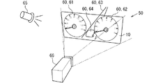
以下、実施形態を図面に基づいて説明する。図1に第1実施形態の車両用表示装置1の構成を示す。車両用表示装置1は車両2に搭載されている。車両用表示装置1は、ディスプレイ10、画像データ記憶部20、視線検出装置30、演算装置40を備えている。
Embodiments will be described below with reference to the drawings. FIG. 1 shows the configuration of a
表示部に相当するディスプレイ10は、車両2のインストルメントパネルに設置されて、車両2に関する種々の情報を表示する。情報は画像として表示される。以下、ディスプレイ10に表示される画像を表示画像とする。表示画像は、写真のような詳細に形状を表現したものに限られず、幾何学的な図形、イラストレーション、絵などと呼ばれるものも含まれる。また、ディスプレイ10には文字も、表示画像として表示される。
The
画像データ記憶部20は、ディスプレイ10に表示する種々の表示画像を作成するためのデータ(以下、画像データ)が記憶されている。表示画像には三次元的に表示される画像も含まれている。三次元的に表示される表示画像については、画像データとして、三次元形状が記憶されている。
The image
視線検出装置30は、運転者の視点および視線方向を検出する。これらを検出するために、視線検出装置30はカメラ31を備えている。図2には、視線検出装置30の設置例を示している。図2の例では、視線検出装置30は、ディスプレイ10の下側に配置されている。視線検出装置30が備えるカメラ31の撮像範囲は、運転者の頭4が含まれるように設定されている。視線検出装置30の設置位置は、図2に示す位置に限られず、運転者の頭4が撮像できる位置であれば、図2に示す位置以外の位置に設置されていてもよい。
The line-of-
視線検出装置30は、カメラ31が撮像した画像を解析して、運転者の目の位置を検出する。より具体的には、目の基準点および動点の位置を検出する。目の基準点を目頭とし、目の動点を虹彩として、これらの位置関係から視線を検出する方法が知られている。また、目の基準点を角膜反射とし、目の動点を瞳孔として、これらの位置関係から視線を検出する方法も知られている。
The line-of-
演算装置40は、CPU、RAM、ROM、I/O、およびこれらの構成を接続するバスラインなどを備えたコンピュータである。ROMには、CPUが実行するプログラムが記憶されている。なお、このプログラムは、非遷移的実体的記録媒体(non- transitory tangible storage medium)に格納されていればよく、その具体的な記憶媒体はROMに限らない。例えばプログラムはフラッシュメモリに保存されていてもよい。CPUがプログラムを実行することは、プログラムに対応する方法が実行されることに相当する。
The
演算装置40は、CPUがROMに格納されているプログラムを実行することによって、図2に示すように、画像データ取得部41、計測値取得部42、運転者情報取得部43、描画処理部44としての機能を実現する。なお、演算装置40が備える機能ブロックの一部または全部は、一つあるいは複数のIC等を用いて(換言すればハードウェアとして)実現してもよい。また、演算装置40が備える機能の一部又は全部を、CPUによるソフトウェアの実行とハードウェア部材の組み合わせによって実現してもよい。
In the
画像データ取得部41は、画像データ記憶部20から画像データを取得する。図3は、仮想空間50に表示対象物60が配置された状態を示している。画像データ取得部41は、この表示対象物60の画像データを取得する。
The image
本実施形態では、仮想空間50に配置された表示対象物60を仮想視点から見た画像が表示画像としてディスプレイ10に表示される。つまり、これら表示対象物60は、ディスプレイ10に表示される物体である。図3に示されている表示対象物60は、具体的には、スピードメータ文字盤61、タコメータ文字盤62、道路63、車64である。なお、車64は自車両を概念的に示している。これらは一例であり、表示対象物60には、図3に示す物以外が含まれていてもよい。たとえば、燃料計、水温計などの種々の計器が表示対象物60に含まれていてもよい。画像データ取得部41は、これら表示対象物60の画像データを取得する。
In the present embodiment, an image of the
図3に示す仮想空間50には、他に照明65、カメラ66が配置されている。照明65は太陽光を示すものであり、カメラ66は運転者の視点および視線を示すものである。このカメラ66により撮像される画像を表示画像としてディスプレイ10に表示する。よって、仮想空間50に配置されたカメラ66は、仮想視点を意味する。
An
計測値取得部42は、表示対象物60に反映させる計測値を取得する。図3に示す例では、表示対象物60に、スピードメータ文字盤61、タコメータ文字盤62が含まれている。したがって、計測値取得部42は、計測値として、車速とエンジン回転速度を取得する。これらの計測値は、これらの計測値を検出するセンサから取得する。
The measurement
運転者情報取得部43は、運転者の視点の位置を取得する。視線検出装置30が運転者の視点の位置を逐次検出している。したがって、運転者情報取得部43は、視線検出装置30から、運転者の視点の位置を逐次取得する。なお、視点は、請求項の視点関連部位の一例である。
The driver
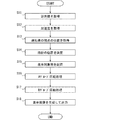
描画処理部44は、画像データ取得部41が取得した画像データ、計測値取得部42が逐次取得した計測値、運転者情報取得部43が逐次取得した運転者の視点の位置に基づいて表示画像を逐次作成し、作成した表示画像をディスプレイ10に表示する。描画処理部44が実行する処理は、図4に示すフローチャートを用いて説明する。なお、図4において、ステップ(以下、ステップを省略)S1は計測値取得部42が実行する処理、S2は運転者情報取得部43が実行する処理である。S3以降は、描画処理部44が実行する。
The
図4に示す処理は、車両2の電源がオンになるなど、ディスプレイ10に表示画像を表示させる条件が成立した後であって、画像データ取得部41が画像データを取得した状態で、周期的に実行される。
The process shown in FIG. 4 is performed after the condition for displaying the display image on the
S1では、計測値を取得する。S2では、運転者の視点の位置を取得する。S3では、S1で取得した計測値に基づいて、仮想空間50に配置する表示対象物60のうち、指針を備える表示対象物60の指針の位置を決定する。
In S1, the measured value is acquired. In S2, the position of the driver's viewpoint is acquired. In S3, the position of the pointer of the
S4では、仮想空間50に、S3で決定した指針の位置を反映させた表示対象物60を配置する。次のS5、S6の処理を行うことで、運転者の視点の位置の角度変化に基づいて回転させた表示対象物60をカメラ66から見た画像をディスプレイ10に表示させる。ただし、本実施形態では、表示対象物60を、運転者の視点の位置の変化角度θよりも回転角度を小さくするAグループと、運転者の視点の位置の変化角度θよりも回転角度を大きくするBグループに分けている。
In S4, the
本実施形態の変化角度θは、運転者の両目の中間位置すなわち頭4の左右方向中心と、表示対象物60別に決定されている回転中心Cを結ぶ線分Gと、基準線分Bとのなす角度を意味する。基準線分Bは、運転者の両目の中間位置が基準位置にあるときの、運転者の両目の中間位置と回転中心とを結ぶ線分である。基準位置は、たとえば、ステアリング中心を通り、車両の前後方向に平行な鉛直平面上の位置とする。図8および図10に、これら線分G、基準線分Bを示している。
The change angle θ of the present embodiment is obtained by dividing the line segment G connecting the center of both eyes of the driver, that is, the center of the
指針の位置など情報を読み取る必要がある画像データはAグループに分類されている。情報を読み取る必要があるとは、形状の位置の少しの違いを認識する必要がある、あるいは、形状の少しの違いを認識する必要があることを意味する。形状の位置の少しの違いを認識する必要があるものとして、指針の位置がある。また、形状の違いを認識する必要があるものとして文字がある。 Image data for which it is necessary to read information such as the position of the pointer is classified into the A group. The need to read the information means that it is necessary to recognize a slight difference in the position of the shape or a small difference in the shape. The position of the pointer is one that requires recognition of a slight difference in the position of the shape. Further, there is a character that needs to recognize the difference in shape.
一方、運転者にとって、情報を読み取るといった作業が必要ない、あるいは、情報を短時間で読み取る必要性が高くない画像データはBグループに分類されている。Aグループに分類されている画像データは請求項の移動抑制画像データに相当し、Bグループに分類されている画像データは請求項の移動促進画像データに相当する。図3の例では、スピードメータ文字盤61、タコメータ文字盤62の画像データはAグループに分類されており、道路63、車64の画像データはBグループに分類されている。 On the other hand, the image data for which the driver does not need to read the information or the information is not required to be read in a short time is classified into the B group. The image data classified into the A group corresponds to the movement suppression image data in the claims, and the image data classified into the B group corresponds to the movement promotion image data in the claims. In the example of FIG. 3, the image data of the speedometer dial 61 and the tachometer dial 62 are classified into the A group, and the image data of the road 63 and the car 64 are classified into the B group.
S5では、Aグループに属する画像データが表す表示対象物60に対して回転処理を行う。Aグループの表示対象物60に対しては、運転者の視点の位置の変化角度θに1よりも小さい正の係数を掛けた角度だけ回転させる。正の係数の具体的数値は、視認性の確保と臨場感あるいは運転感の向上とのバランスを考慮して、実験に基づいて決定する。
In S5, the rotation process is performed on the
図5に、スピードメータ文字盤61、タコメータ文字盤62の回転中心CAを示している。スピードメータ文字盤61およびタコメータ文字盤62は同一平面に配置されている。この平面を以下、メータ配置平面67とする。回転中心CAは、このメータ配置平面67に設定されている。より詳しくは、回転中心CAは、メータ配置平面67において、スピードメータ文字盤61とタコメータ文字盤62との中間位置に設定されている。
FIG. 5 shows the rotation centers C A of the speedometer dial 61 and the tachometer dial 62. The speedometer dial 61 and the tachometer dial 62 are arranged on the same plane. Hereinafter, this plane will be referred to as a
S6では、Bグループに属する画像データが表す表示対象物60に対して回転処理を行う。Bグループの表示対象物60に対しては、運転者の視点の位置の変化角度θに1よりも大きい正の係数を掛けた角度だけ回転させる。Bグループの回転角度を決定する正の係数の具体的数値も、視認性の確保と臨場感あるいは運転感の向上とのバランスを考慮して、実験に基づいて決定する。
In S6, the rotation processing is performed on the
図6に、道路63および車64の回転中心CBを示している。回転中心CBは、仮想空間50においてできるだけ前方に設定される。前方は、角度0度を向いたカメラ66の撮像方向においてカメラ66から遠ざかる方向である。たとえば、仮想空間50において消失点となる位置に回転中心CBを設定する。奥行きが長い形状である道路63は、この消失点に向かう向きに配置する。
FIG. 6 shows the center of rotation C B of the road 63 and the vehicle 64. The rotation center C B is set as far forward as possible in the
図7には、視点の位置がθ=0度のときのスピードメータ文字盤61とタコメータ文字盤62を示している。また、図7には、基準線分Bも示している。なお、図7は、仮想空間50を上方から見た図、すなわち、平面図である。図8〜図10も同様に、仮想空間50を上方から見た図である。図7に示す向きがスピードメータ文字盤61およびタコメータ文字盤62の基準の向きである。図7では、メータ配置平面67が基準線分Bに直交している。
FIG. 7 shows the speedometer dial 61 and the tachometer dial 62 when the position of the viewpoint is θ=0 degree. Further, FIG. 7 also shows a reference line segment B. Note that FIG. 7 is a view of the
これに対して、図8は、運転者の視点の変化角度θがθ1となったときのスピードメータ文字盤61およびタコメータ文字盤62の回転角度θ2を示している。スピードメータ文字盤61およびタコメータ文字盤62の回転角度θ2は、運転者の視点の変化角度θ1に1よりも小さい係数を乗じた角度であることからθ2<θ1である。 On the other hand, FIG. 8 shows the rotation angle θ2 of the speedometer dial 61 and the tachometer dial 62 when the change angle θ of the driver's viewpoint becomes θ1. The rotation angle θ2 of the speedometer dial 61 and the tachometer dial 62 is an angle obtained by multiplying the change angle θ1 of the driver's viewpoint by a coefficient smaller than 1, so that θ2<θ1.
図9には、視点の位置が0度のときの道路63、車64を示している。この図9に示す向きがスピードメータ文字盤61およびタコメータ文字盤62の基準の向きである。図9では、道路63は基準線分Bと平行になっている。これに対して、図10は、運転者の視点の変化角度θがθ1となったときの道路63、車64の回転角度θ3を示している。道路63および車64の回転角度θ3は、運転者の視点の変化角度θ1に1よりも大きい係数を乗じた角度であることからθ1<θ3である。 FIG. 9 shows the road 63 and the vehicle 64 when the viewpoint position is 0 degree. The orientation shown in FIG. 9 is the reference orientation of the speedometer dial 61 and the tachometer dial 62. In FIG. 9, the road 63 is parallel to the reference line segment B. On the other hand, FIG. 10 shows the rotation angles θ3 of the road 63 and the vehicle 64 when the change angle θ of the driver's viewpoint becomes θ1. The rotation angle θ3 of the road 63 and the vehicle 64 is θ1<θ3 because it is an angle obtained by multiplying the change angle θ1 of the driver's viewpoint by a coefficient larger than 1.
続くS7では、S5およびS6で回転処理を行った後の表示対象物60を、カメラ66の位置からみた画像を生成する。生成した画像が表示画像である。カメラ66の位置は、S13で取得した運転者の視点の位置から決定する。また、照明65の位置は、画像生成時点の太陽の位置とする。太陽の位置を決定するために、時刻と進行方位と現在位置から太陽の角度が定まる関係を備えておく。この関係と、実際の時刻、進行方位、現在位置とを用いて照明65の位置を決定する。現在位置は、たとえば、GNSS受信機が検出した位置を用いる。進行方位は、現在位置の軌跡から算出すればよい。
In subsequent S7, an image of the
なお、カメラ66の位置から見たとき、道路63および車64が、スピードメータ文字盤61あるいはタコメータ文字盤62が重なることもある。つまり、Aグループの表示対象物60とBグループの表示対象物60とが重なることもある。この場合、Aグループの画像データから作成する表示画像は、Bグループの画像データから作成する表示画像よりも常に手前になるように表示画像を作成する。表示画像を作成した後、その表示画像をディスプレイ10に出力する。
When viewed from the position of the
[第1実施形態のまとめ]
以上の処理が実行されることで、運転者の視点の位置が0度方向から変化すると、Aグループに属する表示画像およびBグループに属する表示画像は、それぞれ、運転者の視点の位置が0度のときに表示される表示画像に対して回転移動した画像となる。
[Summary of First Embodiment]
When the position of the driver's viewpoint changes from the 0 degree direction by performing the above processing, the display images belonging to the A group and the B group respectively have the driver's viewpoint position of 0 degree. The image is rotated and moved with respect to the display image displayed at.
ただし、Bグループの画像データから作成する表示画像の回転角度は、運転者の視点の位置の変化角度θに対して、1よりも大きい係数を掛けた角度としている。一方、Aグループの画像データから作成する表示画像の回転角度は、その変化角度θに1よりも小さい正の係数を掛けた角度としている。よって、Bグループの表示画像の回転移動量は、Aグループの表示画像の回転移動量よりも大きい。よって、全ての表示画像の回転移動量を、Aグループの表示画像の回転移動量としてしまう場合に比較して、運転者に臨場感を与えることができる。 However, the rotation angle of the display image created from the image data of the B group is an angle obtained by multiplying the change angle θ of the position of the viewpoint of the driver by a coefficient larger than 1. On the other hand, the rotation angle of the display image created from the image data of the A group is the angle obtained by multiplying the change angle θ by a positive coefficient smaller than 1. Therefore, the rotation movement amount of the display image of the B group is larger than the rotation movement amount of the display image of the A group. Therefore, compared to the case where the rotational movement amount of all the display images is set as the rotational movement amount of the display images of the group A, it is possible to give the driver a sense of realism.
また、Aグループの表示画像の回転移動量は、Bグループの表示画像の回転移動量よりも小さくしている。よって、スピードメータ文字盤61、タコメータ文字盤62を作成する画像データなど、必要な情報を読み取る必要がある画像データは、Aグループに分類しておくことにより、必要な情報が読み取りにくくなることも抑制できる。 Further, the rotational movement amount of the display image of the A group is smaller than the rotational movement amount of the display image of the B group. Therefore, it is possible to make it difficult to read necessary information by classifying image data that needs to read necessary information, such as image data for creating the speedometer dial 61 and the tachometer dial 62, into the A group. Can be suppressed.
また、本実施形態では、Aグループに属しているスピードメータ文字盤61とタコメータ文字盤62の回転中心CAをメータ配置平面67に設定している。一方、Bグループに属している道路63と車64の回転中心CBは、仮想空間50において回転中心CAよりも前方に設定している。このようにすることで、道路63と車64の回転中心CBをメータ配置平面67に設定する場合よりも、道路63と車64のディスプレイ10上での移動量が大きくなる。よって、運転者に、より臨場感を与えることができる。
Further, in the present embodiment, the rotation center C A of the speedometer dial 61 and the tachometer dial 62 belonging to the A group is set on the
また、本実施形態では、Aグループの画像データから作成する表示画像を、Bグループの画像データから作成する表示画像よりも常に手前に表示している。これによっても、必要な情報が読み取りにくくなることが抑制される。 Further, in the present embodiment, the display image created from the image data of the A group is always displayed in front of the display image created from the image data of the B group. This also prevents the necessary information from becoming difficult to read.
<第2実施形態>
次に、第2実施形態を説明する。この第2実施形態以下の説明において、それまでに使用した符号と同一番号の符号を有する要素は、特に言及する場合を除き、それ以前の実施形態における同一符号の要素と同一である。また、構成の一部のみを説明している場合、構成の他の部分については先に説明した実施形態を適用できる。
<Second Embodiment>
Next, a second embodiment will be described. In the following description of the second embodiment, elements having the same reference numerals as those used so far are the same as the elements having the same reference numerals in the previous embodiments, unless otherwise specified. Further, when only a part of the configuration is described, the above-described embodiments can be applied to other parts of the configuration.
図11に第2実施形態の車両用表示装置100の構成を示す。車両用表示装置100は、加速度センサ70を備えている。また、演算装置140は、車両加速度取得部145を備えており、第1実施形態とは異なる描画処理部144を備える。
FIG. 11 shows the configuration of the
加速度センサ70は、車両2の幅方向すなわち左右方向の加速度を逐次検出する。なお、これに加えて、車両2の前後方向および上下方向の加速度を検出してもよい。
The
車両加速度取得部145は、加速度センサ70から車両2に生じる左右方向の加速度を逐次取得する。描画処理部144は、車両加速度取得部145が取得した車両2の左右方向の加速度に基づいて表示対象物60の回転角度を決定する点が、第1実施形態の描画処理部44と相違する。
The vehicle
描画処理部144の処理は、図12に示すフローチャートを用いて説明する。図12に示す処理は、図4に代えて実行される処理である。なお、図12において、S11は計測値取得部42が実行する処理であり、S1と同じ処理である。S12は車両加速度取得部145が実行する処理であり、加速度センサ70から車両2の横方向の加速度を取得する。S13は運転者情報取得部43が実行する処理であり、S2と同じ処理である。S14以降は、描画処理部144が実行する。
The processing of the
S14、S15はそれぞれ、図4のS3、S4と同じ処理である。S16では、表示対象物60のうち、Aグループに属する画像データが表す表示対象物60に対して回転処理を行う。ただし、第1実施形態とは異なり、このS16では、Aグループに属する表示対象物60の回転角度は、運転者の視点の変化角度θとする。なお、回転中心CAは第1実施形態と同じである。
S14 and S15 are the same processes as S3 and S4 of FIG. 4, respectively. In S16, of the display objects 60, the
このようにしてAグループの回転角度を決定すると、車両2の左右方向の加速度により運転者の頭4の位置が変化しても、スピードメータ文字盤61およびタコメータ文字盤62を運転者の顔に正対させることができる。
When the rotation angle of the group A is determined in this way, even if the position of the driver's
図13は、このS16の処理の具体例を示している。図13の例では、ステアリング3が短時間で大きく回されたことにより、車両2の左右方向に大きな加速度が生じ、これにより、運転者の頭4の位置が大きく図右側に移動した状態を示している。
FIG. 13 shows a specific example of the process of S16. In the example of FIG. 13, a large acceleration is generated in the left-right direction of the
このように、運転者の頭4の位置が大きく移動しても、第2実施形態では、スピードメータ文字盤61およびタコメータ文字盤62を運転者の顔に正対する。したがって、スピードメータ文字盤61およびタコメータ文字盤62の視認性の低下が抑制できる。
In this way, even if the position of the driver's
S17では、表示対象物60のうち、Bグループに属する画像データが表す表示対象物60に対して回転処理を行う。第2実施形態では、Bグループに属する表示対象物60の回転角度は、S12で取得した加速度の大きさに基づいて決定する。具体的には、左右方向の加速度の大きさと、運転者の視点の変化角度θとの関係を実験に基づいて予め決定しておく。そして、S12で取得した加速度と上記関係から定まる変化角度θに、1よりも大きい係数をかけた値を回転角度とする。
In S17, of the display objects 60, the rotation processing is performed on the display objects 60 represented by the image data belonging to the B group. In the second embodiment, the rotation angle of the
このようにして回転角度を決定すると、Bグループの表示対象物60の回転角度は、運転者の顔に正対させる角度よりも大きな角度となる。つまり、第2実施形態でも、Bグループの表示対象物60の回転移動量はAグループの表示対象物60の回転移動量よりも大きい。
When the rotation angle is determined in this way, the rotation angle of the
図14は、S17の処理の具体例を示している。ただし、図13とは異なり、ステアリング3の操作量は大きくない。そのため、このステアリング3の回転により車両2に生じる左右方向の加速度もそれほど大きくない。その結果、運転者の頭4の位置の変化もそれほど大きくない。しかし、第2実施形態では、Bグループの表示対象物60の回転角度は、車両2の左右方向に生じた加速度から定まる変化角度θに1よりも大きい係数をかけた角度としている。そのため、図14に示すように、道路63および車64に対する回転角度θ5は、運転者の顔の変化角度θ4よりも大きい角度になっている。
FIG. 14 shows a specific example of the process of S17. However, unlike FIG. 13, the operation amount of the
S18では、S16およびS17で回転処理を行った後の表示対象物60を、カメラ66の位置からみた画像を表示画像として生成する。なお、カメラ66の位置、照明65の位置は、第1実施形態と同じ方法で決定する。また、Aグループの画像データから作成する表示画像が、Bグループの画像データから作成する表示画像よりも常に手前になるように表示画像を作成する点も第1実施形態と同じである。表示画像を作成した後、その表示画像をディスプレイ10に出力する。
In S18, the image of the
[第2実施形態のまとめ]
この第2実施形態では、車両2の左右方向の加速度に応じてBグループの表示対象物60の回転角度を決定している。しかも、このBグループの表示対象物60の回転角度は、Aグループの表示対象物60の回転角度よりも大きい。よって、全ての表示画像の回転移動量を、Aグループの画像データから作成される表示画像の回転移動量としてしまう場合に比較して、運転者に臨場感および運転感を与えることができる。
[Summary of Second Embodiment]
In the second embodiment, the rotation angle of the
より具体的には、Bグループの表示対象物60に対する回転角度は、車両2の左右方向に生じた加速度から定まる変化角度θに、1よりも大きい係数をかけた回転角度である。よって、図14に例示しているように、運転者が少しステアリング3を操作しただけでも、道路63および車64が激しく移動する。よって、運転者に臨場感を与えることができる。
More specifically, the rotation angle of the
また、Aグループの表示画像の回転移動量は、Bグループの表示画像の回転移動量よりも小さくなっている。しかも、Aグループの表示画像は、運転者の頭4の位置が変化しても、運転者の顔に正対する回転角度とされる。よって、運転者の頭4の位置が変化しても、Aグループの表示画像に表されている必要な情報が読み取りにくくなることも抑制できる。
Further, the rotation movement amount of the display image of the A group is smaller than the rotation movement amount of the display image of the B group. In addition, the display image of the group A has a rotation angle that faces the driver's face even if the position of the driver's
以上、実施形態を説明したが、開示した技術は上述の実施形態に限定されるものではなく、次の変形例も開示した範囲に含まれ、さらに、下記以外にも要旨を逸脱しない範囲内で種々変更して実施できる。 Although the embodiments have been described above, the disclosed technology is not limited to the above-described embodiments, the following modifications are also included in the disclosed range, and further within the scope other than the following without departing from the gist. Various modifications can be implemented.
<変形例1>
前述の実施形態では、描画処理部44、144は、表示対象物60を回転移動していたが、表示対象物60の移動態様は、回転移動ではなく前後方向への直線移動でもよい。
<
In the above-described embodiment, the
表示対象物60を前後方向へ直線移動させる場合において、運転者の視点関連部位に基づいて移動量を決定する場合には、その視点関連部位の車両前後方向位置の変化量に基づいて、表示対象物60を仮想空間50で前後に移動させる。視点関連部位の車両前後方向位置の変化量と、表示対象物60の前後方向への移動量との対応は予め設定しておく。
In the case of linearly moving the
表示対象物60を前後方向へ直線移動させる場合において、車両2に生じる前後方向の加速度に基づいて移動量を決定する場合には、車両2に生じる前後方向の加速度に基づいて、表示対象物60を仮想空間50で前後に移動させる。車両2に生じる前後方向の加速度と、表示対象物60の前後方向への移動量との対応は予め設定しておく。
In the case where the
<変形例2>
第1実施形態では、運転者の視点の位置に基づいて回転角度を決定していた。しかし、視点の位置に代えて、頭4の位置に基づいて回転角度を決定してもよい。頭4は視点とともに移動するからである。頭4の位置は視点関連部位の一例である。
<
In the first embodiment, the rotation angle is determined based on the position of the driver's viewpoint. However, the rotation angle may be determined based on the position of the
<変形例3>
また、視点の位置に代えて、視線方向を用いて回転角度を決定してもよい。視線方向を検出するためには、前述したように、目の基準点および動点を検出している。よって、視線方向を用いて回転角度を決定する場合にも、視点の位置を検出していることになる。視線を用いる場合、視線の角度変化量に基づいて、表示対象物60の回転角度を決定する。
<
Further, the rotation angle may be determined using the line-of-sight direction instead of the position of the viewpoint. In order to detect the line-of-sight direction, the eye reference point and the moving point are detected as described above. Therefore, the position of the viewpoint is detected even when the rotation angle is determined using the line-of-sight direction. When the line of sight is used, the rotation angle of the
<変形例4>
前述した実施形態では、表示対象物60をAグループとBグループに分けていた。しかし、これに加えて、Cグループを設定してもよい。Cグループは、視点関連部位の位置の変化あるいは車両に生じる加速度が変化しても、全く移動させないグループである。
<
In the above-described embodiment, the
たとえば、ディスプレイ10に表示する情報のうち、点灯するか消灯するかで運転者に情報を伝達する画像をCグループとすることができる。具体的には、シートベルト警告灯などのインジケータをCグループとすることができる。また、別の観点として、表示位置がディスプレイ10の隅部あるいは周縁部にある画像をCグループとすることができる。これらの位置は、もともと運転者にとって視認性のよい位置ではないので、移動させることによる視認性の低下が好ましくなく、また、移動させても、運転者に臨場感を与えにくい位置だからである。
For example, of the information displayed on the
<変形例5>
第1実施形態において、Aグループの表示対象物60に対して、運転者の視点の位置の変化角度θに乗じる係数を0としてもよい。つまり、第1実施形態において、視点関連部位の位置が変化しても、Aグループは移動させなくてもよい。また、第2実施形態でも、車両に生じる加速度によらず、Aグループの移動量を0としてもよい。
<
In the first embodiment, the coefficient for multiplying the change angle θ of the position of the driver's viewpoint with respect to the display objects 60 of the A group may be set to zero. That is, in the first embodiment, the A group may not be moved even if the position of the viewpoint-related part changes. Also in the second embodiment, the movement amount of the A group may be set to 0 regardless of the acceleration generated in the vehicle.
<変形例6>
車両用表示装置に表示する画像にスピードメータ文字盤61、タコメータ文字盤62などの計器類が含まれていなくてもよい。たとえば、車両用表示装置は、ナビゲーション装置として具体化されてもよい。
<Modification 6>
The image displayed on the vehicle display device may not include instruments such as the speedometer dial 61 and the tachometer dial 62. For example, the vehicular display device may be embodied as a navigation device.
<変形例7>
車両2の左右方向の加速度としてヨー角加速度を検出してもよい。ヨー角加速度は、たとえば、ヨーレートセンサが検出するヨーレートを微分することで取得できる。
<Modification 7>
The yaw angular acceleration may be detected as the lateral acceleration of the
<変形例8>
前述の実施形態では、Bグループに属する表示対象物60として道路63を示していた。道路63は、Aグループに属する表示対象物60と比較して奥行き形状、すなわち、前後方向の形状が長い。このように、奥行き形状が長い表示対象物60は、回転中心CBを前方に設定することによって、特に臨場感あるいは運転感を運転者に与えることができる。奥行き形状が長い表示対象物60は道路63に限られない。たとえば、川を表示対象物60としてもよい。
<Modification 8>
In the above-described embodiment, the road 63 is shown as the
<変形例9>
第2実施形態において、Aグループの回転角度、およびBグループの回転角度のいずれか一方を第1実施形態と同じ方法で決定してもよい。
<Modification 9>
In the second embodiment, either the rotation angle of the A group or the rotation angle of the B group may be determined by the same method as in the first embodiment.
<変形例10>
第1、第2実施形態では、Aグループを回転移動させる際の回転中心CAは、Aグループの表示対象物60であるスピードメータ文字盤61およびタコメータ文字盤62が配置されている平面であるメータ配置平面67に設定されていた。しかし、回転中心CAを、Aグループの表示対象物60よりも前方に配置してもよい。換言すれば、Aグループの表示対象物60を、回転中心CAよりも遠方に配置してもよい。
<
In the first and second embodiments, the rotation center C A when the A group is rotationally moved is the plane on which the speedometer dial 61 and the tachometer dial 62 that are the display objects 60 of the A group are arranged. It was set on the
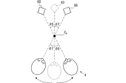
図15には、回転中心CAが運転者と表示対象物60の間にある例を図示している。図15に示す例では、運転者の視点の変化角度θがθ6のとき、Aグループの表示対象物60を、CAを回転中心として角度θ6回転させ、運転者の視点の変化角度θがθ7のとき、Aグループの表示対象物60を、CAを回転中心として角度θ7回転させている。したがって、図15に示す例では、運転者の頭4の位置が変化しても、表示対象物60を運転者の顔に正対する。
FIG. 15 shows an example in which the center of rotation C A is between the driver and the
Aグループの表示対象物60をこのように、角度θ6、θ7だけ回転させたとき、Bグループの表示対象物60の回転移動量は、角度θ6、θ7に1よりも大きい係数を掛けた角度とする。なお、Bグループの回転中心CBも、Aグループの回転中心CAと同様、運転者とBグループの表示対象物60の間に配置することができる。
When the
<変形例11>
第1実施形態では、AグループおよびBグループともに、視点関連部位の変化方向に移動させていた。しかし、Bグループを視点関連部位の変化方向とは反対方向に移動させてもよい。図16には、表示対象物60を運転者の視点の変化方向とは反対方向に移動させている例を示している。表示対象物60はCBを回転中心として回転移動させており、図16において表示対象物60はBグループに属するとする。
<Modification 11>
In the first embodiment, both the A group and the B group are moved in the changing direction of the viewpoint-related part. However, the B group may be moved in the direction opposite to the changing direction of the viewpoint-related part. FIG. 16 shows an example in which the
この変形例11において、表示画像の移動量は、第1実施形態と同じ線分Gと、表示対象物60から回転中心CBに向かう線分Hとの間の角度の変化量である。破線で示す移動前の状態では、線分Gと線分Hとの間の角度は0である。これに対して、実線で示す頭4が移動した後の状態では、線分Gと線分Hとの間の角度はθ7+θ8である。したがって、角度の変化量もθ7+θ8である。
In the modified example 11, the amount of movement of the display image is the amount of change in angle between the line segment G that is the same as in the first embodiment and the line segment H that extends from the
この変形例11において、Aグループの表示対象物60の回転移動量は、これまでの実施形態および変形例にて説明した計算方法で計算することができる。すなわち、この変形例11において、Aグループの表示対象物60の回転移動量は、運転者の視点の変化角度であるθ7に1よりも小さい正の係数を乗じた回転移動量とすることができる。また、運転者の視点変化角度によらず、Aグループの表示対象物60を移動させないとすることもできる。いずれの場合にも、Bグループの表示画像の回転移動量はAグループの表示画像の回転移動量よりも大きくなる。
In the modified example 11, the rotational movement amount of the display objects 60 of the A group can be calculated by the calculation method described in the above-described embodiments and modified examples. That is, in this modification 11, the rotational movement amount of the display objects 60 of the A group can be the rotational movement amount obtained by multiplying θ7, which is the change angle of the driver's viewpoint, by a positive coefficient smaller than 1. .. In addition, the
<変形例12>
変形例11では、Bグループの表示対象物60を視点関連部位の変化方向とは反対方向に回転移動させることを説明した。また、第2実施形態において、Bグループの表示対象物60を、車両2の左右方向の加速度に応じて回転移動させることを説明した。そして、車両2の左右方向の加速度が生じると、その加速度により視点関連部位の位置が変化する。したがって、Bグループの表示対象物を車両2の左右方向の加速度とは反対方向に移動させてもよい。すでに説明した図16は、Bグループの表示対象物60を車両2の左右方向の加速度とは反対方向に移動させている例として見ることもできる。
<
In the modified example 11, it has been described that the
この変形例12でも、表示画像の移動量は、線分Gと線分Hとの間の角度の変化量である。この変形例12において、Aグループの表示対象物60の回転移動量は、第2実施形態および変形例にて説明した計算方法で計算することができる。たとえば、この変形例12において、Aグループの表示対象物60の回転移動量は、移動方向が車両2の左右方向の加速度の方向であって、車両2の左右方向の加速度から推定できる運転者の視点の変化角度以下の回転移動量とすることができる。また、車両2の左右方向の加速度によらず、Aグループの表示対象物60を移動させないとすることもできる。いずれの場合にも、Bグループの表示画像の回転移動量はAグループの表示画像の回転移動量よりも大きくなる。
Also in this
<変形例13>
これまでに、表示対象物60の移動態様として、回転移動と前後方向への直線移動を説明した。これ以外にも、表示対象物60を移動態様として、回転移動に代えて左右方向のスライド移動を採用することもできる。図15や図16を見ると分かるように、運転者から見て回転中心Cが表示対象物60よりも遠方または前方にある場合、表示対象物60は運転者から見て左右方向に移動する。したがって、回転移動に代えて左右方向のスライド移動を採用することもできるのである。
<Modification 13>
So far, the rotational movement and the linear movement in the front-back direction have been described as the movement modes of the
<変形例14>
表示画像をAグループとBグループとに分けつつ、視点関連部位の位置の変化量に応じてそれらの表示画像の表示位置を移動させることで、ディスプレイ10を見る運転者に臨場感ある画像を提供できる。しかし、臨場感のある画像を好まない運転者が存在することも想定される。そこで、視点関連部位の位置の変化量に応じて表示画像を移動させる処理を実行するか、しないかを、ユーザが切り替え可能としてもよい。
<Modification 14>
The display images are divided into the A group and the B group, and the display positions of the display images are moved according to the amount of change in the position of the viewpoint-related portion, thereby providing a realistic image to the driver looking at the
また、Aグループの移動量およびBグループの移動量も、個々のユーザにより好みが異なることが想定される。そこで、視点関連部位の位置の変化量に対するAグループの移動量およびBグループの移動量を、グループ別に、あるいは、AグループとBグループとをまとめて、ユーザが設定できるようになっていてもよい。 Further, it is assumed that the moving amount of the A group and the moving amount of the B group have different preferences depending on individual users. Therefore, the movement amount of the A group and the movement amount of the B group with respect to the amount of change in the position of the viewpoint-related portion may be set by the user for each group or for both the A group and the B group together. ..
1:車両用表示装置 2:車両 3:ステアリング 4:頭 10:ディスプレイ (表示部) 20:画像データ記憶部 30:視線検出装置 31:カメラ 40:演算装置 41:画像データ取得部 42:計測値取得部 43:運転者情報取得部 44:描画処理部 50:仮想空間 60:表示対象物 61:スピードメータ文字盤 62:タコメータ文字盤 63:道路 64:車 65:照明 66:カメラ 67:メータ配置平面 70:加速度センサ 100:車両用表示装置 140:演算装置 144:描画処理部 145:車両加速度取得部 1: Vehicle display device 2: Vehicle 3: Steering 4: Head 10: Display (display unit) 20: Image data storage unit 30: Line-of-sight detection device 31: Camera 40: Arithmetic device 41: Image data acquisition unit 42: Measured value Acquisition unit 43: Driver information acquisition unit 44: Drawing processing unit 50: Virtual space 60: Display object 61: Speedometer dial 62: Tachometer dial 63: Road 64: Car 65: Lighting 66: Camera 67: Meter placement Plane 70: Acceleration sensor 100: Vehicle display device 140: Arithmetic device 144: Drawing processing unit 145: Vehicle acceleration acquisition unit
Claims (12)
運転者の視点または前記視点とともに移動する部位である視点関連部位の位置を取得する運転者情報取得部(43)と、
前記表示部に表示する表示画像を作成するための画像データを取得する画像データ取得部(41)と、
前記画像データに基づいて前記表示画像を作成し、前記表示画像を前記表示部に表示する描画処理部(44)とを備え、
前記画像データは、移動抑制画像データと移動促進画像データとに分けられており、
前記描画処理部は、前記移動促進画像データから作成する前記表示画像の移動量を、前記視点関連部位の位置の変化量に基づいて決定し、かつ、前記移動抑制画像データから作成する前記表示画像の移動量よりも大きくし、かつ、
前記描画処理部は、前記画像データが表す表示対象物を、前記車両の前後方向に平行な鉛直平面と前記鉛直平面に直交する平面との角度が変化する方向に回転移動させて前記表示画像を作成するようになっており、前記表示対象物の回転移動量を、前記視点関連部位から前記画像データの回転中心に向かう線分(G)の角度変化量に基づいて決定する車両用表示装置。 A display unit (10) installed on the vehicle,
A driver information acquisition unit (43) for acquiring the position of a viewpoint of the driver or a position of a viewpoint-related portion that moves together with the viewpoint,
An image data acquisition unit (41) for acquiring image data for creating a display image to be displayed on the display unit;
A drawing processing unit (44) for creating the display image based on the image data and displaying the display image on the display unit;
The image data is divided into movement suppression image data and movement promotion image data,
The drawing processing unit determines a movement amount of the display image created from the movement promotion image data based on a change amount of the position of the viewpoint-related portion, and the display image created from the movement suppression image data. larger than the amount of movement, and,
The drawing processing unit rotates the display object represented by the image data in a direction in which an angle between a vertical plane parallel to the front-rear direction of the vehicle and a plane orthogonal to the vertical plane changes to display the display image. A display device for a vehicle, which is adapted to be created and which determines a rotational movement amount of the display object based on an angular change amount of a line segment (G) extending from the viewpoint-related portion toward a rotation center of the image data.
車両に生じる加速度を取得する車両加速度取得部(145)と、
前記表示部に表示する表示画像を作成するための画像データを取得する画像データ取得部(41)と、
前記画像データに基づいて前記表示画像を作成し、前記表示画像を前記表示部に表示する描画処理部(144)とを備え、
前記画像データは、移動抑制画像データと移動促進画像データとに分けられており、
前記描画処理部は、前記移動促進画像データから作成する前記表示画像の移動量を、前記車両加速度取得部が取得した加速度に基づいて決定し、かつ、前記移動抑制画像データから作成する前記表示画像の移動量よりも大きくする車両用表示装置。 A display unit (10) installed on the vehicle,
A vehicle acceleration acquisition unit (145) for acquiring the acceleration generated in the vehicle;
An image data acquisition unit (41) for acquiring image data for creating a display image to be displayed on the display unit;
A drawing processing unit (144) for creating the display image based on the image data and displaying the display image on the display unit;
The image data is divided into movement suppression image data and movement promotion image data,
The drawing processing unit determines the movement amount of the display image created from the movement promotion image data based on the acceleration acquired by the vehicle acceleration acquisition unit, and the display image created from the movement suppression image data. Display device for vehicles that is larger than the movement amount of the vehicle.
前記描画処理部は、前記移動促進画像データを前記視点関連部位の位置の変化方向とは反対方向に移動させる一方、前記移動抑制画像データは前記視点関連部位の位置の変化方向に移動させる、または、前記視点関連部位の位置が変化しても前記移動抑制画像データは移動させないことで、前記移動促進画像データから作成する前記表示画像の移動量を前記移動抑制画像データから作成する前記表示画像の移動量よりも大きくする、請求項1、3、4のいずれか1項に記載の車両用表示装置。 The movement amount is a change amount of an angle between a line segment (G) extending from the viewpoint-related portion toward the rotation center of the image data and a line segment (H) extending from the image data toward the rotation center,
The drawing processing unit moves the movement promotion image data in a direction opposite to the direction in which the position of the viewpoint-related portion changes, while moving the movement suppression image data in a direction in which the position of the viewpoint-related region changes. , The movement suppression image data is not moved even if the position of the viewpoint-related part changes, so that the movement amount of the display image created from the movement promotion image data is changed from the display image created from the movement suppression image data. The vehicle display device according to any one of claims 1, 3 , and 4 , wherein the display device is made larger than the movement amount.
前記描画処理部は、前記画像データが表す表示対象物を回転移動させて前記表示画像を作成するようになっており、前記表示対象物の回転移動量を、前記車両加速度取得部が検出する前記車両の幅方向の加速度に基づいて決定する請求項2に記載の車両用表示装置。 The vehicle acceleration acquisition unit acquires the widthwise acceleration of the vehicle,
The drawing processing unit is configured to rotate the display object represented by the image data to create the display image, and detect the rotational movement amount of the display object by the vehicle acceleration acquisition unit. The vehicle display device according to claim 2, which is determined based on the acceleration in the width direction of the vehicle.
前記描画処理部は、前記移動促進画像データを、前記車両の幅方向の加速度とは反対方向に移動させる一方、前記移動抑制画像データは前記車両の幅方向の加速度の方向に移動させる、または、前記車両の加速度によらず前記移動抑制画像データは移動させないことで、前記移動促進画像データから作成する前記表示画像の移動量を前記移動抑制画像データから作成する前記表示画像の移動量よりも大きくする、請求項7に記載の車両用表示装置。 The movement amount is a line segment (G) from the driver's viewpoint or a viewpoint-related part that is a part that moves together with the viewpoint to the center of rotation of the image data and a line segment (H) from the image data to the center of rotation. Is the change in angle between
The drawing processing unit moves the movement promotion image data in a direction opposite to the widthwise acceleration of the vehicle, while the movement suppression image data moves in the widthwise acceleration direction of the vehicle, or By not moving the movement suppression image data regardless of the acceleration of the vehicle, the movement amount of the display image created from the movement promotion image data is larger than the movement amount of the display image created from the movement suppression image data. The vehicle display device according to claim 7 .
Priority Applications (4)
| Application Number | Priority Date | Filing Date | Title |
|---|---|---|---|
| DE112018003715.0T DE112018003715B4 (en) | 2017-07-19 | 2018-07-04 | VEHICLE DISPLAY DEVICE |
| PCT/JP2018/025291 WO2019017198A1 (en) | 2017-07-19 | 2018-07-04 | Display device for vehicle and display control device |
| CN201880047202.8A CN110914094B (en) | 2017-07-19 | 2018-07-04 | Display device for vehicle and display control device |
| US16/741,942 US11320660B2 (en) | 2017-07-19 | 2020-01-14 | Vehicle display device and display control device |
Applications Claiming Priority (2)
| Application Number | Priority Date | Filing Date | Title |
|---|---|---|---|
| JP2017140168 | 2017-07-19 | ||
| JP2017140168 | 2017-07-19 |
Publications (3)
| Publication Number | Publication Date |
|---|---|
| JP2019018841A JP2019018841A (en) | 2019-02-07 |
| JP2019018841A5 JP2019018841A5 (en) | 2019-07-25 |
| JP6708227B2 true JP6708227B2 (en) | 2020-06-10 |
Family
ID=65352863
Family Applications (1)
| Application Number | Title | Priority Date | Filing Date |
|---|---|---|---|
| JP2018111301A Active JP6708227B2 (en) | 2017-07-19 | 2018-06-11 | Vehicle display |
Country Status (1)
| Country | Link |
|---|---|
| JP (1) | JP6708227B2 (en) |
Family Cites Families (4)
| Publication number | Priority date | Publication date | Assignee | Title |
|---|---|---|---|---|
| JP2007030531A (en) * | 2005-07-22 | 2007-02-08 | Calsonic Kansei Corp | Display device for vehicle |
| JP4924903B2 (en) * | 2007-11-14 | 2012-04-25 | マツダ株式会社 | Vehicle display device |
| JP5181939B2 (en) * | 2008-09-03 | 2013-04-10 | アイシン・エィ・ダブリュ株式会社 | VEHICLE INSTRUMENT DISPLAY DEVICE, VEHICLE INSTRUMENT DISPLAY METHOD, AND COMPUTER PROGRAM |
| JP6265713B2 (en) * | 2013-12-02 | 2018-01-24 | 矢崎総業株式会社 | Graphic meter device |
-
2018
- 2018-06-11 JP JP2018111301A patent/JP6708227B2/en active Active
Also Published As
| Publication number | Publication date |
|---|---|
| JP2019018841A (en) | 2019-02-07 |
Similar Documents
| Publication | Publication Date | Title |
|---|---|---|
| JP6540817B2 (en) | Display device for vehicle and display method for vehicle | |
| JP6775188B2 (en) | Head-up display device and display control method | |
| US10510276B1 (en) | Apparatus and method for controlling a display of a vehicle | |
| JP6369106B2 (en) | Head-up display device | |
| KR101975154B1 (en) | Vehicle display device and vehicle display method | |
| JP4702437B2 (en) | Vehicle display device | |
| JP2010524102A (en) | Method and control device for displaying roadway progress | |
| CN111034186B (en) | Surrounding vehicle display method and surrounding vehicle display device | |
| EP3776156A1 (en) | Image control apparatus, display apparatus, movable body, and image control method | |
| JP2017105259A (en) | Vehicular information display apparatus | |
| KR20110114485A (en) | Method and device for tracking a position of object marking | |
| WO2019189619A1 (en) | Image control apparatus, display apparatus, movable body, and image control method | |
| JP2024029051A (en) | In-vehicle display device, method and program | |
| EP3776152B1 (en) | Image control apparatus, display apparatus, movable body, and image control method | |
| WO2019189393A1 (en) | Image control apparatus, display apparatus, movable body, and image control method | |
| CN110914094B (en) | Display device for vehicle and display control device | |
| WO2019017198A1 (en) | Display device for vehicle and display control device | |
| JP2017021019A (en) | Vehicular display apparatus and vehicular display method | |
| JP2014213636A (en) | Vehicular display device | |
| JP6708227B2 (en) | Vehicle display | |
| CN110774894B (en) | Display device for vehicle | |
| JP2024005026A (en) | Vehicle display controller, vehicle display device, vehicle, vehicle display control method, and vehicle display control program | |
| JP6405930B2 (en) | In-vehicle display device | |
| JP2022154082A (en) | Display correction system, display system, display correction method, and program | |
| JP2017195533A (en) | Display method and driving support apparatus |
Legal Events
| Date | Code | Title | Description |
|---|---|---|---|
| A521 | Request for written amendment filed |
Free format text: JAPANESE INTERMEDIATE CODE: A523 Effective date: 20190620 |
|
| A621 | Written request for application examination |
Free format text: JAPANESE INTERMEDIATE CODE: A621 Effective date: 20190620 |
|
| TRDD | Decision of grant or rejection written | ||
| A01 | Written decision to grant a patent or to grant a registration (utility model) |
Free format text: JAPANESE INTERMEDIATE CODE: A01 Effective date: 20200421 |
|
| A61 | First payment of annual fees (during grant procedure) |
Free format text: JAPANESE INTERMEDIATE CODE: A61 Effective date: 20200504 |
|
| R151 | Written notification of patent or utility model registration |
Ref document number: 6708227 Country of ref document: JP Free format text: JAPANESE INTERMEDIATE CODE: R151 |
|
| R250 | Receipt of annual fees |
Free format text: JAPANESE INTERMEDIATE CODE: R250 |