JP6704255B2 - Medical observation device, medical observation system, and image shake correction method - Google Patents
Medical observation device, medical observation system, and image shake correction method Download PDFInfo
- Publication number
- JP6704255B2 JP6704255B2 JP2016007621A JP2016007621A JP6704255B2 JP 6704255 B2 JP6704255 B2 JP 6704255B2 JP 2016007621 A JP2016007621 A JP 2016007621A JP 2016007621 A JP2016007621 A JP 2016007621A JP 6704255 B2 JP6704255 B2 JP 6704255B2
- Authority
- JP
- Japan
- Prior art keywords
- unit
- vibration
- observation
- image
- imaging
- Prior art date
- Legal status (The legal status is an assumption and is not a legal conclusion. Google has not performed a legal analysis and makes no representation as to the accuracy of the status listed.)
- Active
Links
Images


Classifications
-
- A—HUMAN NECESSITIES
- A61—MEDICAL OR VETERINARY SCIENCE; HYGIENE
- A61B—DIAGNOSIS; SURGERY; IDENTIFICATION
- A61B90/00—Instruments, implements or accessories specially adapted for surgery or diagnosis and not covered by any of the groups A61B1/00 - A61B50/00, e.g. for luxation treatment or for protecting wound edges
- A61B90/20—Surgical microscopes characterised by non-optical aspects
-
- A—HUMAN NECESSITIES
- A61—MEDICAL OR VETERINARY SCIENCE; HYGIENE
- A61B—DIAGNOSIS; SURGERY; IDENTIFICATION
- A61B1/00—Instruments for performing medical examinations of the interior of cavities or tubes of the body by visual or photographical inspection, e.g. endoscopes; Illuminating arrangements therefor
- A61B1/04—Instruments for performing medical examinations of the interior of cavities or tubes of the body by visual or photographical inspection, e.g. endoscopes; Illuminating arrangements therefor combined with photographic or television appliances
- A61B1/045—Control thereof
-
- A—HUMAN NECESSITIES
- A61—MEDICAL OR VETERINARY SCIENCE; HYGIENE
- A61B—DIAGNOSIS; SURGERY; IDENTIFICATION
- A61B1/00—Instruments for performing medical examinations of the interior of cavities or tubes of the body by visual or photographical inspection, e.g. endoscopes; Illuminating arrangements therefor
- A61B1/04—Instruments for performing medical examinations of the interior of cavities or tubes of the body by visual or photographical inspection, e.g. endoscopes; Illuminating arrangements therefor combined with photographic or television appliances
- A61B1/05—Instruments for performing medical examinations of the interior of cavities or tubes of the body by visual or photographical inspection, e.g. endoscopes; Illuminating arrangements therefor combined with photographic or television appliances characterised by the image sensor, e.g. camera, being in the distal end portion
-
- A—HUMAN NECESSITIES
- A61—MEDICAL OR VETERINARY SCIENCE; HYGIENE
- A61B—DIAGNOSIS; SURGERY; IDENTIFICATION
- A61B90/00—Instruments, implements or accessories specially adapted for surgery or diagnosis and not covered by any of the groups A61B1/00 - A61B50/00, e.g. for luxation treatment or for protecting wound edges
- A61B90/20—Surgical microscopes characterised by non-optical aspects
- A61B90/25—Supports therefor
-
- A—HUMAN NECESSITIES
- A61—MEDICAL OR VETERINARY SCIENCE; HYGIENE
- A61B—DIAGNOSIS; SURGERY; IDENTIFICATION
- A61B90/00—Instruments, implements or accessories specially adapted for surgery or diagnosis and not covered by any of the groups A61B1/00 - A61B50/00, e.g. for luxation treatment or for protecting wound edges
- A61B90/36—Image-producing devices or illumination devices not otherwise provided for
- A61B90/361—Image-producing devices, e.g. surgical cameras
-
- G—PHYSICS
- G02—OPTICS
- G02B—OPTICAL ELEMENTS, SYSTEMS OR APPARATUS
- G02B23/00—Telescopes, e.g. binoculars; Periscopes; Instruments for viewing the inside of hollow bodies; Viewfinders; Optical aiming or sighting devices
- G02B23/24—Instruments or systems for viewing the inside of hollow bodies, e.g. fibrescopes
- G02B23/2407—Optical details
-
- G—PHYSICS
- G02—OPTICS
- G02B—OPTICAL ELEMENTS, SYSTEMS OR APPARATUS
- G02B23/00—Telescopes, e.g. binoculars; Periscopes; Instruments for viewing the inside of hollow bodies; Viewfinders; Optical aiming or sighting devices
- G02B23/24—Instruments or systems for viewing the inside of hollow bodies, e.g. fibrescopes
- G02B23/2476—Non-optical details, e.g. housings, mountings, supports
- G02B23/2484—Arrangements in relation to a camera or imaging device
-
- G—PHYSICS
- G02—OPTICS
- G02B—OPTICAL ELEMENTS, SYSTEMS OR APPARATUS
- G02B27/00—Optical systems or apparatus not provided for by any of the groups G02B1/00 - G02B26/00, G02B30/00
- G02B27/64—Imaging systems using optical elements for stabilisation of the lateral and angular position of the image
- G02B27/646—Imaging systems using optical elements for stabilisation of the lateral and angular position of the image compensating for small deviations, e.g. due to vibration or shake
-
- H—ELECTRICITY
- H04—ELECTRIC COMMUNICATION TECHNIQUE
- H04N—PICTORIAL COMMUNICATION, e.g. TELEVISION
- H04N23/00—Cameras or camera modules comprising electronic image sensors; Control thereof
- H04N23/56—Cameras or camera modules comprising electronic image sensors; Control thereof provided with illuminating means
-
- H—ELECTRICITY
- H04—ELECTRIC COMMUNICATION TECHNIQUE
- H04N—PICTORIAL COMMUNICATION, e.g. TELEVISION
- H04N23/00—Cameras or camera modules comprising electronic image sensors; Control thereof
- H04N23/60—Control of cameras or camera modules
- H04N23/68—Control of cameras or camera modules for stable pick-up of the scene, e.g. compensating for camera body vibrations
- H04N23/681—Motion detection
- H04N23/6812—Motion detection based on additional sensors, e.g. acceleration sensors
-
- H—ELECTRICITY
- H04—ELECTRIC COMMUNICATION TECHNIQUE
- H04N—PICTORIAL COMMUNICATION, e.g. TELEVISION
- H04N23/00—Cameras or camera modules comprising electronic image sensors; Control thereof
- H04N23/60—Control of cameras or camera modules
- H04N23/68—Control of cameras or camera modules for stable pick-up of the scene, e.g. compensating for camera body vibrations
- H04N23/682—Vibration or motion blur correction
- H04N23/683—Vibration or motion blur correction performed by a processor, e.g. controlling the readout of an image memory
-
- H—ELECTRICITY
- H04—ELECTRIC COMMUNICATION TECHNIQUE
- H04N—PICTORIAL COMMUNICATION, e.g. TELEVISION
- H04N23/00—Cameras or camera modules comprising electronic image sensors; Control thereof
- H04N23/60—Control of cameras or camera modules
- H04N23/68—Control of cameras or camera modules for stable pick-up of the scene, e.g. compensating for camera body vibrations
- H04N23/682—Vibration or motion blur correction
- H04N23/685—Vibration or motion blur correction performed by mechanical compensation
- H04N23/687—Vibration or motion blur correction performed by mechanical compensation by shifting the lens or sensor position
-
- A—HUMAN NECESSITIES
- A61—MEDICAL OR VETERINARY SCIENCE; HYGIENE
- A61B—DIAGNOSIS; SURGERY; IDENTIFICATION
- A61B1/00—Instruments for performing medical examinations of the interior of cavities or tubes of the body by visual or photographical inspection, e.g. endoscopes; Illuminating arrangements therefor
- A61B1/00147—Holding or positioning arrangements
- A61B1/00149—Holding or positioning arrangements using articulated arms
-
- A—HUMAN NECESSITIES
- A61—MEDICAL OR VETERINARY SCIENCE; HYGIENE
- A61B—DIAGNOSIS; SURGERY; IDENTIFICATION
- A61B34/00—Computer-aided surgery; Manipulators or robots specially adapted for use in surgery
- A61B34/20—Surgical navigation systems; Devices for tracking or guiding surgical instruments, e.g. for frameless stereotaxis
- A61B2034/2046—Tracking techniques
- A61B2034/2048—Tracking techniques using an accelerometer or inertia sensor
-
- A—HUMAN NECESSITIES
- A61—MEDICAL OR VETERINARY SCIENCE; HYGIENE
- A61B—DIAGNOSIS; SURGERY; IDENTIFICATION
- A61B90/00—Instruments, implements or accessories specially adapted for surgery or diagnosis and not covered by any of the groups A61B1/00 - A61B50/00, e.g. for luxation treatment or for protecting wound edges
- A61B90/50—Supports for surgical instruments, e.g. articulated arms
- A61B2090/5025—Supports for surgical instruments, e.g. articulated arms with a counter-balancing mechanism
- A61B2090/504—Supports for surgical instruments, e.g. articulated arms with a counter-balancing mechanism with a counterweight
-
- A—HUMAN NECESSITIES
- A61—MEDICAL OR VETERINARY SCIENCE; HYGIENE
- A61B—DIAGNOSIS; SURGERY; IDENTIFICATION
- A61B90/00—Instruments, implements or accessories specially adapted for surgery or diagnosis and not covered by any of the groups A61B1/00 - A61B50/00, e.g. for luxation treatment or for protecting wound edges
- A61B90/50—Supports for surgical instruments, e.g. articulated arms
- A61B2090/506—Supports for surgical instruments, e.g. articulated arms using a parallelogram linkage, e.g. panthograph
-
- G—PHYSICS
- G02—OPTICS
- G02B—OPTICAL ELEMENTS, SYSTEMS OR APPARATUS
- G02B7/00—Mountings, adjusting means, or light-tight connections, for optical elements
- G02B7/001—Counterbalanced structures, e.g. surgical microscopes
-
- H—ELECTRICITY
- H04—ELECTRIC COMMUNICATION TECHNIQUE
- H04N—PICTORIAL COMMUNICATION, e.g. TELEVISION
- H04N23/00—Cameras or camera modules comprising electronic image sensors; Control thereof
- H04N23/50—Constructional details
- H04N23/555—Constructional details for picking-up images in sites, inaccessible due to their dimensions or hazardous conditions, e.g. endoscopes or borescopes
Landscapes
- Health & Medical Sciences (AREA)
- Life Sciences & Earth Sciences (AREA)
- Physics & Mathematics (AREA)
- Surgery (AREA)
- Engineering & Computer Science (AREA)
- Optics & Photonics (AREA)
- Veterinary Medicine (AREA)
- Heart & Thoracic Surgery (AREA)
- Medical Informatics (AREA)
- Molecular Biology (AREA)
- Animal Behavior & Ethology (AREA)
- General Health & Medical Sciences (AREA)
- Public Health (AREA)
- Pathology (AREA)
- Biomedical Technology (AREA)
- Nuclear Medicine, Radiotherapy & Molecular Imaging (AREA)
- Multimedia (AREA)
- Signal Processing (AREA)
- General Physics & Mathematics (AREA)
- Oral & Maxillofacial Surgery (AREA)
- Astronomy & Astrophysics (AREA)
- Biophysics (AREA)
- Radiology & Medical Imaging (AREA)
- Microscoopes, Condenser (AREA)
- Adjustment Of Camera Lenses (AREA)
- Instruments For Viewing The Inside Of Hollow Bodies (AREA)
- Accessories Of Cameras (AREA)
- Studio Devices (AREA)
Description
本開示は、医療用観察装置、医療用観察システム及び画揺れ補正方法に関する。 The present disclosure relates to a medical observation device, a medical observation system, and an image shake correction method.
外科手術において、顕微鏡部等の術部を拡大観察可能な観察用機器(以下、観察部ともいう)によって術部を観察しながら手術を行う手法が用いられている。その際、当該観察部の位置及び姿勢を高精度に移動、固定するために、当該観察部をアーム部(支持部)によって保持する医療用観察装置が用いられている。 In the surgical operation, a technique is used in which an operation is performed while observing the operation part with an observation device capable of magnifying and observing the operation part such as a microscope part (hereinafter, also referred to as an observation part). At that time, in order to move and fix the position and posture of the observation section with high accuracy, a medical observation apparatus that holds the observation section by an arm section (support section) is used.
ここで、医療用観察装置においては、例えば手術室内を移動する医療スタッフの歩行等により、観察部が振動してしまう場合がある。このような振動は、拡大観察における観察像の揺れ(画揺れ)を引き起こすため、この揺れが収まるまで作業を行えないこととなり、術者の精神的な負担を増加させるとともに、手術の効率を低下させる原因となっていた。 Here, in the medical observation apparatus, the observation unit may vibrate due to walking of a medical staff moving in the operating room, for example. Such vibrations cause shakes (image shakes) of the observation image in magnified observation, which means that work cannot be performed until the shakes subside, increasing the mental burden on the operator and reducing the efficiency of surgery. Was causing
そこで、観察対象を拡大観察するための観察用機器においては、振動がより抑制された安定的な観察像を得るための技術が開発されている。例えば、特許文献1には、顕微鏡において、振動を検出するための加速度センサを備え、当該加速度センサによって検出された振動と逆位相で対物レンズを駆動させることにより、安定的な観察像を得ることを可能にする技術が開示されている。
Therefore, in an observation device for magnifying and observing an observation target, a technique for obtaining a stable observation image in which vibration is further suppressed has been developed. For example, in
しかしながら、特許文献1に記載の技術は、アーム部によって支持される顕微鏡部を対象としたものではなく、また、手術時に術部を観察する用途を前提としたものでもない。このように、特許文献1に記載の技術は、必ずしも医療用観察装置に適したものとは言えなかった。
However, the technique described in
そこで、本開示では、より振動の影響の少ない安定的な観察像を得ることが可能な、新規かつ改良された医療用観察装置、医療用観察システム及び画揺れ補正方法を提案する。 Therefore, the present disclosure proposes a new and improved medical observation apparatus, medical observation system, and image shake correction method that can obtain a stable observation image with less influence of vibration.
本開示によれば、術部を拡大観察するための観察部と、前記観察部の振動を検出する振動センサと、前記観察部を支持する支持部と、前記振動センサによる検出値に基づいて、前記観察部によって観察される画像の揺れを補正する画揺れ補正を行う制御部と、を備える、医療用観察装置が提供される。 According to the present disclosure, an observation unit for magnifying and observing a surgical site, a vibration sensor that detects vibration of the observation unit, a support unit that supports the observation unit, and a detection value by the vibration sensor, There is provided a medical observation apparatus, comprising: a control unit that performs image shake correction that corrects shake of an image observed by the observation unit.
また、本開示によれば、術部を撮影する撮像部、前記撮像部の振動を検出する振動センサ、前記撮像部を支持する支持部、及び、前記振動センサによる検出値に基づいて前記撮像部によって撮影される画像の揺れを補正する画揺れ補正を行う制御部、を有する医療用観察装置と、前記医療用観察装置によって画揺れ補正が施された画像を表示する表示装置と、を備える、医療用観察システムが提供される。 Further, according to the present disclosure, an image capturing unit that captures an image of a surgical site, a vibration sensor that detects vibration of the image capturing unit, a support unit that supports the image capturing unit, and the image capturing unit based on a detection value by the vibration sensor. A medical observation device having a control unit that performs image shake correction for correcting the image shake captured by the medical observation device, and a display device that displays an image subjected to image shake correction by the medical observation device. A medical observation system is provided.
また、本開示によれば、術部を拡大観察するための観察部、前記観察部の振動を検出する振動センサ、及び前記観察部を支持する支持部、を有する医療用観察装置において、前記振動センサによる検出値に基づいて、前記観察部によって観察される画像の揺れを補正する画揺れ補正を行う、画揺れ補正方法が提供される。 Further, according to the present disclosure, in the medical observation device having an observation unit for magnifying and observing a surgical site, a vibration sensor that detects vibration of the observation unit, and a support unit that supports the observation unit, the vibration There is provided an image shake correction method for performing image shake correction for correcting the shake of an image observed by the observation unit based on a value detected by a sensor.
本開示によれば、振動センサによって観察部の振動が検出され、その検出値に基づいて、当該観察部によって得られる画像の揺れを補正する画揺れ補正が行われる。従って、より振動の影響の少ない安定的な観察像を得ることが可能になる。よって、手術時における術者の精神的負担を軽減するとともに、手術を円滑に進めることが可能になる。 According to the present disclosure, the vibration sensor detects the vibration of the observation unit, and based on the detected value, the image shake correction is performed to correct the shake of the image obtained by the observation unit. Therefore, it is possible to obtain a stable observation image with less influence of vibration. Therefore, it is possible to reduce the mental burden on the operator during the operation and to smoothly proceed with the operation.
以上説明したように本開示によれば、より振動の影響の少ない安定的な観察像を得ることが可能になる。なお、上記の効果は必ずしも限定的なものではなく、上記の効果とともに、又は上記の効果に代えて、本明細書に示されたいずれかの効果、又は本明細書から把握され得る他の効果が奏されてもよい。 As described above, according to the present disclosure, it is possible to obtain a stable observation image with less influence of vibration. Note that the above effects are not necessarily limited, and in addition to or in place of the above effects, any of the effects shown in this specification, or other effects that can be grasped from this specification. May be played.
以下に添付図面を参照しながら、本開示の好適な実施の形態について詳細に説明する。なお、本明細書及び図面において、実質的に同一の機能構成を有する構成要素については、同一の符号を付することにより重複説明を省略する。 Hereinafter, preferred embodiments of the present disclosure will be described in detail with reference to the accompanying drawings. In the present specification and the drawings, constituent elements having substantially the same functional configuration are designated by the same reference numerals, and a duplicate description will be omitted.
なお、説明は以下の順序で行うものとする。
1.観察装置の構成
2.画揺れ補正処理の詳細
3.画揺れ補正方法
4.補足
The description will be given in the following order.
1. Configuration of observation device 2. Details of image shake correction processing 3. Image stabilization method 4. Supplement
なお、以下では、本開示の実施形態に係る観察装置に対して各種の操作を行うユーザのことを、便宜的に術者と記載する。ただし、当該記載は観察装置を使用するユーザを限定するものではなく、観察装置に対する各種の操作は、他の医療スタッフ等、あらゆるユーザによって実行されてよい。 Note that, hereinafter, a user who performs various operations on the observation device according to the embodiment of the present disclosure is referred to as an operator for convenience. However, the above description does not limit the user who uses the observation device, and various operations on the observation device may be executed by any user such as other medical staff.
(1.観察装置の構成)
図1を参照して、本開示の好適な一実施形態に係る観察システムの構成について説明するとともに、当該観察システムを構成する観察装置の構成について説明する。図1は、本実施形態に係る観察システムの一構成例を示す図である。
(1. Configuration of observation device)
With reference to FIG. 1, the configuration of an observation system according to a preferred embodiment of the present disclosure will be described, and the configuration of an observation device that constitutes the observation system will be described. FIG. 1 is a diagram showing a configuration example of an observation system according to this embodiment.
本実施形態に係る観察システム1は、手術や検査等の医療行為に用いられる医療用観察装置である。図1を参照すると、本実施形態に係る観察システム1は、顕微鏡部110を備え、当該顕微鏡部110によって患者の術部を撮影する観察装置10と、観察装置10によって撮影された術部の画像(静止画像及び動画像)を表示する表示装置20と、から構成される。手術時又は検査時には、術者は、観察装置10によって撮影され表示装置20に表示された画像を参照しながら、術部を観察し、当該術部に対して各種の処置を行う。
The
(表示装置)
表示装置20は、上述したように、観察装置10によって撮影された患者の術部の画像を表示する。表示装置20は、例えば手術室の壁面等、手術室内において術者によって視認され得る場所に設置される。表示装置20の種類は特に限定されず、表示装置20としては、例えばCRT(Cathode Ray Tube)ディスプレイ装置、液晶ディスプレイ装置、プラズマディスプレイ装置、EL(Electro−Luminescence)ディスプレイ装置等、各種の公知の表示装置が用いられてよい。また、表示装置20は、必ずしも手術室内に設置されなくてもよく、ヘッドマウントディスプレイ(HMD:Head Mounted Display)や眼鏡型のウェアラブルデバイスのように、術者が身に付けて使用するデバイスに搭載されてもよい。
(Display device)
As described above, the
(観察装置)
観察装置10は、患者の術部を拡大観察するための顕微鏡部110と、顕微鏡部110を保持する支持部120(アーム部120)と、支持部120の一端が接続され顕微鏡部110及び支持部120を支持するベース部130と、観察装置10の動作を制御する制御装置140と、を備える。
(Observation device)
The
(ベース部)
ベース部130は、顕微鏡部110及び支持部120を支持する。ベース部130は板状の形状を有する架台131と、架台131の下面に設けられる複数のキャスター132と、を有する。架台131の上面に支持部120の一端が接続され、架台131から延伸される支持部120の他端(先端)に顕微鏡部110が接続される。また、観察装置10は、キャスター132を介して床面と接地し、当該キャスター132によって床面上を移動可能に構成されている。
(Base part)
The
なお、以下の説明では、観察装置10が設置される床面に対して鉛直な方向をz軸方向と定義する。z軸方向のことを上下方向又は垂直方向とも呼称する。また、z軸方向と互いに直交する2方向を、それぞれ、x軸方向及びy軸方向と定義する。x−y平面と平行な方向のことを水平方向とも呼称する。
In the following description, the direction perpendicular to the floor on which the
(顕微鏡部)
顕微鏡部110は、患者の術部を拡大観察するための顕微鏡鏡体によって構成される。図示する例では、顕微鏡部110の光軸方向は、z軸方向と略一致している。顕微鏡部110は、電子撮像式の顕微鏡に対応する構成を有しており、略円筒形状を有する筒状部112と、筒状部112内に設けられる撮像部111と、から構成される。また、撮像部111は、対物レンズ、ズームレンズ等の光学系と、当該光学系を通過した光により被写体(すなわち術部)の像を撮影する撮像素子と、から構成される。また、本実施形態では、顕微鏡部110に、撮像部111の振動を検出するための振動センサ113が設けられる。
(Microscope section)
The
筒状部112の下端の開口面には、撮像部111を保護するためのカバーガラスが設けられる。筒状部112の内部には、光源も設けられており、撮影時には、当該光源からカバーガラス越しに被写体に対して照明光が照射される。当該照明光の被写体からの反射光(観察光)が、カバーガラスを介して撮像部111に入射することにより、当該撮像部111によって術部の画像に係る信号(画像信号)が取得される。
A cover glass for protecting the
撮像部111としては、各種の公知の電子撮像式の顕微鏡部に用いられている構成が適用されてよいため、ここではその詳細な説明は省略する。例えば、撮像部111の撮像素子としては、CCD(Charge Coupled Device)センサやCMOS(Complementary Metal−Oxide−Semiconductor)センサ等の各種の公知の撮像素子が適用されてよい。また、撮像部111は、1対の撮像素子を備えた、いわゆるステレオカメラとして構成されてもよい。また、撮像部111の光学系についても、各種の公知の構成が適用され得る。更に、撮像部111には、AF(Auto Focus)機能や光学ズーム機能等の、一般的に電子撮像式の顕微鏡部に備えられる各種の機能が搭載され得る。
As the
振動センサ113は、撮像部111の振動(例えば、振動方向、振幅及び振動の周波数等)を検出するセンサである。振動センサ113としては、加速度センサ、ジャイロセンサ等、一般的に振動の検出に用いられる各種の公知のセンサが用いられてよい。ただし、後述するように、本実施形態では、振動センサ113の検出値に基づいて、撮像部111によって撮影された画像の揺れ(すなわち、観察像の揺れ)を補正する画揺れ補正処理が行われるため、振動センサ113としては、少なくとも撮像素子の受光面と平行な面内での振動を検出し得るものが用いられる。また、振動センサ113は、撮像部111の振動をより高精度に検出できるように、撮像部111の近傍に設置されることが好ましい。更に、顕微鏡部110の小型化のため、振動センサ113も、比較的小型であることが好ましい。
The
顕微鏡部110によって取得された画像信号は制御装置140に送信され、当該制御装置140において、当該画像信号に対して、例えばガンマ補正、ホワイトバランスの調整、電子ズーム機能に係る拡大及び画素間補正等、各種の画像処理が行われる。当該画像処理では、画像を表示するために一般的に行われる各種の画像処理が行われてよい。また、本実施形態では、振動センサ113による検出値も制御装置140に送信される。更に、制御装置140は、撮像部111の振動モードを決定する機能を有しており、当該制御装置140は、決定した振動モード、及び当該検出値に基づいて、画揺れ補正処理を実行する。なお、画揺れ補正処理の詳細については、下記(2.画揺れ補正処理の詳細)で改めて説明する。上記の画像処理が行われるとともに画揺れ補正が反映された画像信号が、手術室に設けられる表示装置20に送信され、当該表示装置20に術部の画像が、例えば光学ズーム機能及び/又は電子ズーム機能によって所望の倍率に適宜拡大されて表示される。なお、制御装置140と表示装置20との間の通信は、有線又は無線の公知の各種の方式で実現されてよい。
The image signal acquired by the
なお、顕微鏡部110に、上記の画像処理を行うための処理回路が設けられていてもよく、上記の画像処理は、制御装置140によって行われず、顕微鏡部110の当該処理回路によって行われてもよい。この場合、顕微鏡部110に搭載される処理回路において適宜画像処理が施された後の画像情報が、顕微鏡部110から手術室に設けられる表示装置20に送信され得る。また、この場合、顕微鏡部110と表示装置20との間の通信は、有線又は無線の公知の各種の方式で実現されてよい。
The
顕微鏡部110には、顕微鏡部110の動作を制御するための各種のスイッチが設けられる。例えば、顕微鏡部110には、当該顕微鏡部110の撮影条件を調整するためのズームスイッチ151(ズームSW151)及びフォーカススイッチ152(フォーカスSW152)、並びに、支持部120の動作モードを変更するための動作モード変更スイッチ153(動作モード変更SW153)が設けられる。
The
術者は、ズームSW151及びフォーカスSW152を操作することにより、顕微鏡部110の倍率及び焦点距離を、それぞれ調整することができる。また、術者は、動作モード変更SW153を操作することにより、支持部120の動作モードを、固定モード及びフリーモードのいずれかに切り替えることができる。
The operator can adjust the magnification and the focal length of the
ここで、固定モードは、支持部120に設けられる各回転軸における回転がブレーキにより規制されることにより、顕微鏡部110の位置及び姿勢が固定される動作モードである。フリーモードは、ブレーキが解除されることにより、支持部120に設けられる各回転軸における回転が自由に可能な状態であり、術者による直接的な操作によって顕微鏡部110の位置及び姿勢を調整可能な動作モードである。ここで、直接的な操作とは、術者が例えば手で顕微鏡部110を把持し、当該顕微鏡部110を直接移動させる操作のことを意味する。例えば、術者が動作モード変更SW153を押下している間は支持部120の動作モードがフリーモードとなり、術者が動作モード変更SW153から手を離している間は支持部120の動作モードが固定モードとなる。
Here, the fixed mode is an operation mode in which the position and orientation of the
なお、これらのスイッチは必ずしも顕微鏡部110に設けられなくてもよい。本実施形態では、これらのスイッチと同等の機能を有する、操作入力を受け付けるための機構が観察装置10に設けられればよく、当該機構の具体的な構成は限定されない。例えば、これらのスイッチは、観察装置10の他の部位に設けられてもよい。また、例えば、リモコン等の入力装置を用いて、これらのスイッチに対応する命令が、遠隔的に観察装置10に対して入力されてもよい。
Note that these switches do not necessarily have to be provided in the
また、簡単のため、図1では顕微鏡部110の筒状部112を簡易的に単純な円筒形状の部材として図示しているが、筒状部112には、術者によって把持される把持部が設けられてもよい。当該把持部は、術者が把持する取っ手等の構造が、筒状部112の外周に形成されることによって実現され得る。あるいは、当該把持部は、筒状部112の形状が、術者によって把持されやすい形状に形成されることによって実現され得る。例えば、フリーモード時には、術者が筒状部112を直接手で握った状態で、顕微鏡部110を移動させる操作が想定され得る。この際、術者は、動作モード変更SW153を押下しながら、顕微鏡部110を移動させる操作を行うこととなるため、筒状部112の形状及び動作モード変更SW153の配置位置は、フリーモード時の術者の操作性を考慮して適宜決定され得る。また、ズームSW151及びフォーカスSW152の配置位置も、同様に、術者の操作性を考慮して適宜決定されてよい。
Further, for simplification, in FIG. 1, the
(制御装置)
制御装置140は、例えばCPU(Central Processing Unit)やDSP(Digital Signal Pocessor)等のプロセッサ、又はこれらのプロセッサと記憶素子等がともに搭載された制御基板等によって構成され、所定のプログラムに従った演算処理を実行することにより、観察装置10の動作を制御する。
(Control device)
The
例えば、制御装置140は、上記動作モード変更SW153を介した術者の操作入力に応じて、支持部120の各関節部に設けられるブレーキの駆動を制御することにより、上述した支持部120の動作モードを切り替える機能を有する。また、例えば、制御装置140は、上記ズームSW151及びフォーカスSW152を介した術者の操作入力に応じて、顕微鏡部110の撮像部111の光学系を適宜駆動させ、顕微鏡部110の倍率及び焦点距離を調整する機能を有する。また、制御装置140は、顕微鏡部110によって取得された画像信号に対して、各種の画像処理を施し、処理後の画像信号を表示装置20に表示させる機能を有する。この際、本実施形態では、制御装置140によって画揺れ補正処理が行われ、画揺れがより抑制された画像を表示装置20に表示させる。
For example, the
なお、図示する例では、制御装置140は、顕微鏡部110、支持部120及びベース部130とは異なる構成として設けられ、ケーブルによってベース部130と接続されているが、本実施形態はかかる例に限定されない。例えば、制御装置140と同様の機能を実現するプロセッサや制御基板等が、ベース部130内に配置されてもよい。また、制御装置140と同様の機能を実現するプロセッサや制御基板等が顕微鏡部110の内部に組み込まれることにより、制御装置140と顕微鏡部110とが一体的に構成されてもよい。
In the illustrated example, the
(支持部)
支持部120は、顕微鏡部110を保持し、顕微鏡部110を3次元的に移動させるとともに、移動後の顕微鏡部110の位置及び姿勢を固定する。本実施形態では、支持部120は、6自由度を有するバランスアームとして構成されている。ただし、本実施形態はかかる例に限定されず、支持部120は、用途に応じて顕微鏡部110を適宜移動し得るように構成されればよく、他の異なる数の自由度を有するように構成されてもよい。
(Support part)
The
支持部120には、6自由度に対応する6つの回転軸(第1軸O1、第2軸O2、第3軸O 3 、第4軸O4、第5軸O5及び第6軸O6)が設けられる。以下では、説明のため便宜的に、各回転軸を構成する部材をまとめて、回転軸部と呼称することとする。例えば、回転軸部は、軸受、当該軸受に回動可能に挿通されるシャフト、及び回転軸における回転を規制するブレーキ等によって構成され得る。後述する平行四辺形リンク機構240も、回転軸部の一つとみなすことができる。
The
支持部120は、各回転軸に対応する第1回転軸部210、第2回転軸部220、第3回転軸部230、第4回転軸部240、第5回転軸部250、第6回転軸部260と、これら第1回転軸部210〜第6回転軸部260によって互いに回動可能に接続される第1アーム部271、第2アーム部272、第3アーム部273及び第4アーム部274と、顕微鏡部110及び支持部120全体としてのモーメントの釣り合いを取るためのカウンターウエイト280と、によって構成される。なお、第4回転軸部240は、平行四辺形リンク機構240に対応する。
The
なお、以下の説明では、支持部120の構成について説明する際に、顕微鏡部110が設けられる側を先端側又は先端部等とも呼称し、ベース部130に近い側を基端側又は基端部等とも呼称することとする。
In the following description, when describing the configuration of the
第1回転軸部210は、略円筒形状を有し、その中心軸が顕微鏡部110の筒状部112の中心軸と略一致するように、顕微鏡部110の筒状部112の基端部に接続される。第1回転軸部210は、顕微鏡部110の光軸と略一致する方向を回転軸方向(第1軸O1方向)として、顕微鏡部110を回動可能に支持する。図1に示す例では、第1軸O1は、z軸と略平行な回転軸として設けられている。第1回転軸部210によって第1軸O1まわりに顕微鏡部110が回動することにより、顕微鏡部110による撮像画像の向きが調整されることとなる。
The first
なお、図示する例では、第1回転軸部210を構成する円筒形状の筐体内に、顕微鏡部110の撮像部111の一部が格納されている。すなわち、顕微鏡部110及び第1回転軸部210が一体的な部材として構成されている。ただし、本実施形態はかかる例に限定されず、第1回転軸部210及び顕微鏡部110は、互いに別個の部材として構成されてもよい。
In the illustrated example, a part of the
第1回転軸部210には、第1軸O1とは略垂直な方向に延伸する第1アーム部271の先端が接続される。また、第1アーム部271の基端には、当該第1アーム部271の延伸方向と略平行な方向を回転軸方向(第2軸O2方向)として第1アーム部271を回動可能に支持する第2回転軸部220が設けられる。第2軸O2は、第1軸O1とは略垂直な回転軸であり、図1に示す例ではy軸と略平行な回転軸として設けられている。第2回転軸部220によって、第2軸O2を回転軸として顕微鏡部110及び第1アーム部271が回動することにより、顕微鏡部110のx軸方向の位置が調整されることとなる。
The tip of a
第2回転軸部220には、第1軸O1及び第2軸O2と互いに略垂直な方向に延伸する第2アーム部272の先端が接続される。また、第2アーム部272の基端側は略L字状に屈曲しており、折り曲げられた短辺に当たる位置に、当該第2アーム部272の長辺に当たる部位の延伸方向と略平行な方向を回転軸方向(第3軸O3方向)として第2アーム部272を回動可能に支持する第3回転軸部230が設けられる。第3軸O3は、第1軸O1及び第2軸O2と略垂直な回転軸であり、図1に示す例ではx軸と略平行な回転軸として設けられている。第3回転軸部230によって、第3軸O3を回転軸として顕微鏡部110、第1アーム部271及び第2アーム部272が回動することにより、顕微鏡部110のy軸方向の位置が調整されることとなる。
A tip of a
このように、支持部120は、第2軸O2及び第3軸O3まわりの回転がそれぞれ制御されることにより、顕微鏡部110の姿勢が制御されるように構成される。つまり、第2回転軸部220及び第3回転軸部230は、顕微鏡部110の姿勢を規定する回転軸部であり得る。
In this way, the
第3回転軸部230の基端側には、平行四辺形リンク機構240の上辺の先端が接続される。平行四辺形リンク機構240は、平行四辺形の形状に配置される4つのアーム(アーム241、242、243、244)と、当該平行四辺形の略頂点に対応する位置にそれぞれ設けられる4つの関節部(関節部245、246、247、248)と、によって構成される。
The tip of the upper side of the
第3回転軸部230に対して、第3軸O3と略平行な方向に延伸するアーム241の先端が接続される。アーム241の先端付近には関節部245が、基端付近には関節部246がそれぞれ設けられる。関節部245、246には、アーム241の延伸方向と略垂直な、互いに略平行な回転軸(第4軸O4)まわりに回動可能に、それぞれ、アーム242、243の先端が接続される。更に、アーム242、243の基端には、それぞれ、関節部247、248が設けられる。これら関節部247、248には、第4軸O4まわりに回動可能に、かつ、アーム241に対して略平行に、アーム244の先端及び基端がそれぞれ接続される。
The tip of an
このように、平行四辺形リンク機構240を構成する4つの関節部は、互いに略平行な略同一方向の回転軸(第4軸O4)を有し、当該第4軸O4まわりに互いに連動して動作する。図1に示す例では、第4軸O4は、y軸と略平行な回転軸として設けられている。つまり、平行四辺形リンク機構240は、互いに異なる位置に配置され同一方向の回転軸で互いに連動して回転する複数の関節部を有するように構成され、一端での動作を他端に伝達する伝達機構として振る舞う。平行四辺形リンク機構240が設けられることにより、平行四辺形リンク機構240よりも先端側の構成(すなわち、顕微鏡部110、第1回転軸部210、第2回転軸部220、第3回転軸部230、第1アーム部271及び第2アーム部272)の動きが、平行四辺形リンク機構240の基端側に伝達されることとなる。
As described above, the four joint portions that form the
アーム242の基端から所定の距離離れた部位には、当該アーム242の延伸方向と垂直な方向を回転軸方向(第5軸O5方向)として、平行四辺形リンク機構240を回動可能に支持する第5回転軸部250が設けられる。第5軸O5は、第4軸O4と略平行な回転軸であり、図1に示す例ではy軸と略平行な回転軸として設けられている。第5回転軸部250には、z軸方向に延設する第3アーム部273の先端が接続されており、顕微鏡部110、第1アーム部271、第2アーム部272及び平行四辺形リンク機構240は、第5回転軸部250を介して、第5軸O5を回転軸として第3アーム部273に対して回動可能に構成される。
The
第3アーム部273は略L字型の形状を有しており、その基端側は、床面と略平行になるように折り曲げられている。第3アーム部273の当該床面と略平行な面には、第5軸O5と直交する回転軸(第6軸O6)まわりに第3アーム部273を回動可能な第6回転軸部260が接続される。図1に示す例では、第6軸O6は、z軸と略平行な回転軸として設けられている。
The
図示する例では、第6回転軸部260は、鉛直方向に延伸する第4アーム部274と一体的に構成されている。すなわち、第4アーム部274の先端が、第3アーム部273の基端の床面と略平行な面に接続される。また、第4アーム部274の基端は、ベース部130の架台131の上面に接続される。当該構成により、第6回転軸部260を介して、顕微鏡部110、第1アーム部271、第2アーム部272、平行四辺形リンク機構240及び第3アーム部273が、第6軸O6を回転軸としてベース部130に対して回動する。
In the illustrated example, the sixth
平行四辺形リンク機構240の下辺を構成するアーム244は、上辺を構成するアーム241よりも長尺に形成されており、当該アーム242の、平行四辺形リンク機構240の第3回転軸部230が接続される部位と対角に位置する端は、平行四辺形リンク機構240の外部に延出されている。延出されたアーム244の端には、カウンターウエイト280が設けられる。カウンターウエイト280は、自身よりも先端側に配置される各構成(すなわち、顕微鏡部110、第1回転軸部210、第2回転軸部220、第3回転軸部230、第1アーム部271、第2アーム部272及び平行四辺形リンク機構240)の質量によって、第4軸O4まわりに発生する回転モーメント及び第5軸O5まわりに発生する回転モーメントを相殺可能なように、その質量及び配置位置が調整されている。
The
また、第5回転軸部250の配置位置は、当該第5回転軸部250よりも先端側に配置される各構成の重心が第5軸O5上に位置するように調整されている。更に、第6回転軸部260の配置位置は、当該第6回転軸部260よりも先端側に配置される各構成の重心が第6軸O6上に位置するように調整されている。
Further, the arrangement position of the fifth
カウンターウエイト280の質量及び配置位置、第5回転軸部250の配置位置、及び第6回転軸部260の配置位置がこのように構成されることにより、支持部120は、顕微鏡部110及び支持部120全体としてモーメントの釣り合いが取れたバランスアームとして構成され得る。支持部120をバランスアームとして構成することにより、術者が顕微鏡部110を直接的な操作によって移動させようとした場合に、あたかも無重力下であるかのようなより小さい外力で当該顕微鏡部110を移動させることが可能となる。従って、ユーザの操作性を向上させることができる。
With the mass and arrangement position of the
支持部120の第1回転軸部210〜第6回転軸部260には、それぞれ、第1回転軸部210〜第6回転軸部260における回転を規制するブレーキが設けられる。なお、平行四辺形リンク機構240は、4つの関節部(関節部245〜248)が互いに連動して回転するため、平行四辺形リンク機構240に対するブレーキは、これら4つの関節部の少なくともいずれかに設けられればよい。これらのブレーキの駆動は、制御装置140によって制御される。制御装置140からの制御により、これらのブレーキが一斉に解除されることにより、支持部120の動作モードがフリーモードに移行する。また、同じく制御装置140からの制御により、これらのブレーキが一斉に駆動されることにより、支持部120の動作モードが固定モードに移行する。
The first
なお、第1回転軸部210〜第6回転軸部260に設けられるブレーキとしては、一般的なバランスアームに用いられる各種のブレーキが適用されてよく、その具体的な機構は限定されない。例えば、これらのブレーキは、機械的に駆動するものであってもよいし、電気的に駆動する電磁ブレーキであってもよい。
As the brakes provided on the first
以上、図1を参照して、本実施形態に係る観察システム1及び本実施形態に係る観察装置10の構成について説明した。以上説明したように、本実施形態に係る観察装置10では、撮像部111の振動を検出するための振動センサ113が設けられる。また、制御装置140が、撮像部111の振動モードを検出する機能を有する。そして、制御装置140が、決定した振動モード及び振動センサ113による検出値に基づいて、画揺れ補正を行う。従って、より画揺れの少ない、安定的な画像を得ることが可能になる。
The configurations of the
なお、本実施形態では、第1回転軸部210〜第6回転軸部260に、それぞれ、振動抑制機構が設けられてもよい。当該振動抑制機構は、例えば動吸振器であり、ダンパ等の制振部材からなり、各回転軸部における振動を抑制することができる。
In the present embodiment, each of the first
ここで、図2及び図3を参照して、支持部120の各回転軸部に設けられ得る振動抑制機構の具体的ないくつかの構成例について説明する。図2は、各回転軸部に設けられ得る振動抑制機構の一構成例を示す図である。図2を参照すると、振動抑制機構401は、筒形状の第1の部材403と第2の部材405を接続する際にこれらの部材間に設けられ、これらの部材間における振動の伝達を抑制する機能を有する。具体的には、この構成例では、制振対象である筒形状の第1の部材403(制振対象部材403)の内部に、第2の部材405(錘側部材405)が軸方向(図中上下方向)に摺動可能に嵌め込まれることにより、両者が接続されている。この際、制振対象部材403と錘側部材405との間には、粘性抵抗要素として粘弾性部材407及びバネ409が設けられる。振動抑制機構401は、当該粘弾性部材407及び当該バネ409から構成される、動吸振器である。なお、粘弾性部材407は、例えばシリコンゴム、ウレタンゴム等のゴム材からなる、機械的性質とバネ要素としての性質を併せ持つものである。
Here, with reference to FIG. 2 and FIG. 3, some specific configuration examples of the vibration suppressing mechanism that can be provided in each rotating shaft portion of the
粘弾性部材407及びバネ409は、制振対象部材403及び錘側部材405の振動に応じて軸方向に伸縮し、この振動を減衰する機能を有する。粘弾性部材407及びバネ409の特性に応じて振動抑制機構401の固有振動数が決定されるが、この固有振動数が制振対象である支持部120の固有振動数と略一致する場合に、その制振効果を最も大きく発揮することができる。従って、振動抑制機構401は、粘弾性部材407及びバネ409を、異なる特性を有するものに交換可能に構成されてよい。これにより、支持部120の構成に応じて、振動抑制機構401の固有振動数が当該支持部120の固有振動数と略一致するように当該振動抑制機構401を適宜構成することができ、大きな制振効果を得ることができる。
The
また、図3は、各回転軸部に設けられ得る振動抑制機構の他の構成例を示す図である。図3を参照すると、振動抑制機構451は、略棒形状の第1の部材453と第2の部材455を接続する際にこれらの部材間に設けられ、これらの部材間における振動の伝達を抑制する機能を有する。具体的には、この構成例では、第1の部材453の接続端に、ゴム等の振動を吸収可能な弾性部材で形成される凹形状の受座459が設けられる。また、第2の部材455の接続端に、外径が他の部位よりも細く形成された軸部457が設けられる。そして、受座459の凹部にこの第2の部材455の軸部457が挿入された状態で、第1の部材453、受座459及び軸部457がねじ461によって固定されることにより、第1の部材453と第2の部材455が接続される。この受座459が、微振動を吸収する振動抑制機構451を構成し得る。なお、このとき、ねじ461と第1の部材453との間にも、ゴム等の振動を吸収可能な弾性部材(図示せず)が介在されてもよく、受座459及び当該弾性部材によって振動抑制機構451が構成されてもよい。
Further, FIG. 3 is a diagram showing another configuration example of the vibration suppressing mechanism that can be provided on each rotating shaft portion. Referring to FIG. 3, the vibration suppressing mechanism 451 is provided between the substantially rod-shaped
図示するように、受座459は凹形状を有するため、3軸方向の全ての振動を好適に抑制し得る。このように、振動抑制機構451によれば、第1の部材453及び第2の部材455のいずれか一方において生じた振動が他方に伝達されることが、より効果的に抑制され得る。
As shown in the figure, since the seat 459 has a concave shape, it is possible to suitably suppress all vibrations in the three axial directions. As described above, according to the vibration suppressing mechanism 451, it is possible to more effectively suppress the transmission of the vibration generated in one of the
以上、図2及び図3を参照して、支持部120の各回転軸部に設けられ得る振動抑制機構のいくつかの構成例について説明した。なお、当該振動抑制機構としては、図示するもの以外にも、各種の公知のものを用いることができる。
In the above, with reference to FIG. 2 and FIG. 3, some configuration examples of the vibration suppressing mechanism that can be provided on each rotating shaft portion of the supporting
当該振動抑制機構が設けられることにより、顕微鏡部110(すなわち、撮像部111)の振動が抑制されるため、更に画揺れの少ない画像を得ることができる。つまり、本実施形態では、画揺れの補正(抑制)について、上述した制御装置140によるいわばアクティブな画揺れの補正に加えて、第1回転軸部210〜第6回転軸部260に設けられる振動抑制機構によるいわばパッシブな画揺れの抑制が行われてもよい。このように、ソフトウェア的な方法及びハードウェア的な方法の2種類の方法を組み合わせることにより、画揺れ補正をより効果的に行うことが可能になる。
Since the vibration suppressing mechanism is provided, the vibration of the microscope unit 110 (that is, the imaging unit 111) is suppressed, and thus an image with less image shake can be obtained. That is, in the present embodiment, regarding the correction (suppression) of the image shake, in addition to the so-called active image shake correction by the
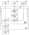
(2.画揺れ補正処理の詳細)
図4を参照して、以上説明した観察装置10において実行される、本実施形態に係る画揺れ補正処理について詳細に説明する。図4は、本実施形態に係る画揺れ補正処理を実現するための制御部の機能構成の一例を示すブロック図である。
(2. Details of image shake correction processing)
The image shake correction process according to the present embodiment, which is executed in the
図4を参照すると、本実施形態に係る画揺れ補正処理を実現するための制御部340は、その機能として、画揺れ補正部341と、表示制御部346と、を有する。また、画揺れ補正部341は、その機能として、振動モード決定部342と、制御パラメータ算出部343と、補正量算出部344と、画像処理部345と、を有する。制御部340のこれらの機能が、図1に示す制御装置140に搭載されることにより、観察装置10において画揺れ補正処理が実行される。
Referring to FIG. 4, the
図4では、説明のため、制御部340以外の他の機能ブロックも図示している。撮像部310は、図1に示す顕微鏡部110の撮像部111に対応する。撮像部310は、撮影した術部の画像についての情報を、画像処理部345に提供する。
In FIG. 4, for the sake of explanation, functional blocks other than the
操作部320は、図1に示す顕微鏡部110に設けられるスイッチ類(ズームSW151、フォーカスSW152及び動作モード変更SW153)等、術者が観察装置10に対して指示入力をするための入力装置に対応する。操作部320に対する術者の操作入力についての情報は、振動モード決定部342に提供される。
The
振動検出部330は、図1に示す顕微鏡部110に設けられる振動センサ113に対応する。振動検出部330は、撮像部111の振動の検出値を、補正量算出部344に提供する。
The
表示部350は、図1に示す表示装置20に対応する。表示部350は、表示制御部346からの制御により、画揺れ補正が施された術部の画像を表示する。
The
制御部340の機能について詳細に説明する。振動モード決定部342は、操作部320に対する術者の操作入力についての情報に基づいて、撮像部111の振動モードを決定する。ここで、振動モードとは、撮像部111の振動の状態を、当該振動の特性に応じて分類したものである。
The function of the
本実施形態では、手術中に撮像部111に生じ得る振動として、以下の3つの振動を想定している。
In the present embodiment, the following three vibrations are assumed as vibrations that can occur in the
振動1:歩行床振動
医療スタッフ等が手術室内を歩行することにより生じる振動。当該振動の周波数は、例えば、1〜100Hz程度である。
Vibration 1: Walking floor vibration Vibration generated by medical staff walking in the operating room. The frequency of the vibration is, for example, about 1 to 100 Hz.
振動2:撮像部移動振動
フリーモードにおいて術者が顕微鏡部110(すなわち、撮像部111)を移動させることにより生じる振動。当該振動の周波数は、例えば、1〜15Hz程度である。
Vibration 2: Vibration of moving image pickup unit Vibration generated when the operator moves the microscope unit 110 (that is, the image pickup unit 111) in the free mode. The frequency of the vibration is, for example, about 1 to 15 Hz.
振動3:撮像部固定振動
術者が顕微鏡部110(すなわち、撮像部111)を移動させ位置を決めた後、フリーモードから固定モードに移行し、顕微鏡部110から手を離すことにより生じる振動。当該振動の周波数は、例えば、0.1〜10Hz程度である。
Vibration 3: Fixed Vibration of Imaging Unit Vibration generated when the operator moves the microscope unit 110 (that is, the imaging unit 111) to determine the position, then shifts from the free mode to the fixed mode, and releases the
振動モード決定部342は、撮像部111にこれらのうちのいずれの振動が生じている可能性が高いかを判断し、これらの振動のいずれか、又はこれらの振動の組み合わせとして、撮像部111の振動モードを決定する。
The vibration
具体的には、歩行床振動は、手術中に常時発生している可能性が高い。従って、振動モード決定部342は、操作部320に対する術者の操作入力にかかわらず、当該歩行床振動が撮像部111に生じている可能性が高いと判断する。
Specifically, walking floor vibration is likely to be constantly occurring during surgery. Therefore, the vibration
一方、撮像部移動振動及び撮像部固定振動は、上記のように、術者による顕微鏡部110に対する操作に応じて生じる。このとき、術者が動作モード変更SW153を押下している間は、支持部120の動作モードがフリーモードであるので、撮像部移動振動が生じている可能性が高い。また、術者が動作モード変更SW153から手を離した瞬間は、支持部120の動作モードがフリーモードから固定モードに移行した瞬間であるので、その後の所定の時間は撮像部固定振動が生じている可能性が高い。
On the other hand, the moving vibration of the imaging unit and the fixed vibration of the imaging unit are generated in accordance with the operation of the
従って、振動モード決定部342は、動作モード変更SW153が押下されている間(すなわち、操作部320から、術者の操作入力についての情報として、動作モード変更SW153が押下されている旨の情報が入力されている間)は、撮像部移動振動が撮像部111に生じている可能性が高いと判断する。また、振動モード決定部342は、動作モード変更SW153が押下された状態から解放された状態に移行した後の所定の時間(すなわち、操作部320から、術者の操作入力についての情報として、動作モード変更SW153が押下されている状態から解放された状態に移行した旨の情報が入力されてから、所定の時間)は、撮像部固定振動が撮像部111に生じている可能性が高いと判断する。
Therefore, the vibration
まとめると、本実施形態では、振動モード決定部342は、操作部320に対する術者の操作入力に応じて、以下の3種類の振動モードを決定する。
In summary, in the present embodiment, the vibration
振動モード決定部342は、動作モード変更SW153が押下されている場合には、歩行床振動及び撮像部移動振動がともに撮像部111に生じている、という振動モードを決定する(以下、振動モード1とも呼称する)。
The vibration
また、振動モード決定部342は、動作モード変更SW153が押下された状態から解放された状態に移行した場合には、その後の所定の時間、歩行床振動及び撮像部固定振動がともに撮像部111に生じている、という振動モードを決定する(以下、振動モード2とも呼称する)。なお、当該所定の時間は、実験やシミュレーション等に基づいて決定すればよい。例えば、顕微鏡部110の位置を固定して手を離した後に顕微鏡部110(撮像部111)に生じる振動を実際に測定し、又はシミュレーションによって計算し、その測定結果又は計算結果に対して周波数解析等を行い、撮像部固定振動と思われる振動が持続している時間を調べることにより、当該所定の時間を決定することができる。
Further, when the operation
また、振動モード決定部342は、上記以外の場合には、歩行床振動が撮像部111に生じている、という振動モードを決定する(以下、振動モード3とも呼称する)。
Further, the vibration
振動モード決定部342は、決定した撮像部111の振動モードについての情報を、制御パラメータ算出部343に提供する。なお、振動モードについての情報(例えば、振動モードの種類についての情報、及び各振動モードに含まれる振動の種類についての情報)は、観察装置10に設けられる記憶部(図示せず)に予め格納されていてよい。例えば、当該振動モードについての情報としては、術者又は観察システム1の設計者等により、撮像部111に生じ得ることが予測される振動についての情報、及び予測され得る撮像部111の振動モードについての情報が、予め当該記憶部に入力され得る。振動モード決定部342は、当該記憶部を参照することにより、予め設定されているいくつかの振動モードの中から、術者の操作に応じた適切な振動モードを選択し、決定することができる。
The vibration
制御パラメータ算出部343は、振動モード決定部342によって決定された撮像部111の振動モードに基づいて、画揺れ補正のための制御パラメータを算出する。
The control
ここで、本実施形態では、画揺れ補正の方法として、電子式の補正方法及び光学式の補正方法のいずれかを用いることができる。電子式の補正方法とは、撮像素子によって取得された画像信号に対する画像処理の段階で、検出された振動状態に基づいて、撮像素子の画素ごとの観察光の取り込み位置を補正することにより、画揺れを補正する方法である。一方、光学式の補正方法とは、検出された振動状態に基づいて、撮像部310の光学系(例えばレンズ等)又は撮像素子の位置を移動させることにより、撮像素子における観察光の受光位置を調整し、画揺れを補正する方法である。
Here, in the present embodiment, either an electronic correction method or an optical correction method can be used as the image shake correction method. The electronic correction method is a method of correcting the image capturing position of each pixel of the image sensor based on the detected vibration state at the stage of image processing for the image signal acquired by the image sensor, thereby correcting the image. This is a method of correcting shaking. On the other hand, the optical correction method is to move the position of the optical system (for example, a lens) of the
ただし、これらの方法を比較すると、光学式の補正方法では、レンズや撮像素子を移動させる駆動機構が必要となる。これに対して、電子式の補正方法は、画像信号に対する電子的な処理によって実行可能であるため、顕微鏡部110の構成をより簡易に、より小型にすることができる。そのため、本実施形態では、好適に電子式の補正方法が用いられる。なお、図4に示す制御部340の機能構成も、画揺れ補正処理において電子式の補正方法が用いられる場合に対応する機能構成を図示している。また、以降の制御部340についての説明も、電子式の補正方法が用いられる場合を例に挙げて説明することとする。
However, comparing these methods, the optical correction method requires a drive mechanism for moving the lens and the image pickup device. On the other hand, since the electronic correction method can be executed by electronic processing on the image signal, the configuration of the
制御パラメータ算出部343は、撮像部111の振動モードに基づいて、撮像部111に生じているであろう振動の状態(例えば周波数特性等)についての情報を得ることができる。例えば、振動モード1が決定されている場合であれば、制御パラメータ算出部343は、歩行床振動(例えば周波数1〜100Hz程度の振動)と撮像部移動振動(例えば周波数1〜15Hz程度の振動)とが合成された振動が、撮像部111において生じていると判断することができる。制御パラメータ算出部343は、この振動を高速フーリエ変換(FFT:Fast Fourier Transform)等を用いて解析し、その振動の特性(例えば、ゲイン特性及び位相特性等)を取得する。
The control
そして、制御パラメータ算出部343は、その振動モードに対応する振動の特性に基づいて、電子式の補正方法において補正量(具体的には、撮像素子における画素の取り込み位置、及び当該取り込み位置の時間変化等)を算出するために用いられる各種の制御パラメータを算出する。当該制御パラメータは、各種の公知な電子式の補正方法において用いられるパラメータと同様であってよい。例えば、制御パラメータ算出部343は、制御パラメータとして、各種フィルタ(HPF(High Pass Filter)及びLPF(Low Pass Filter))のフィルタ特性、積分係数及び位相補償量等を算出する。
Then, the control
制御パラメータ算出部343は、算出した制御パラメータについての情報を、補正量算出部344に提供する。なお、制御パラメータ算出部343は、上述した振動モードについての情報が格納された記憶部を参照することにより、以上説明した制御パラメータの算出処理を実行することができる。
The control
補正量算出部344は、制御パラメータ算出部343によって算出された制御パラメータ、及び振動検出部330から提供された撮像部111の振動の検出値に基づいて、画揺れ補正を行うための補正量を算出する。図4に示す構成例であれば、補正量算出部344は、電子式の画揺れ補正に係る補正量として、撮像素子における画素の取り込み位置、及び当該取り込み位置の時間変化等を算出する。補正量算出部344は、算出した補正量についての情報を、画像処理部345に提供する。
The correction
画像処理部345は、撮像部310によって取得された画像信号に対して、当該画像信号に基づく画像を表示部350に表示させるための各種の画像処理を施す。当該画像処理としては、例えば、ガンマ補正、ホワイトバランスの調整、電子ズーム機能に係る拡大及び画素間補正等、画像表示のために一般的に行われる各種の信号処理が行われてよい。これらの処理においては、各種の公知の手法が用いられてよいため、その詳細な説明は省略する。
The
また、画像処理部345は、当該画像処理において、補正量算出部344によって算出された補正量に基づいて、画揺れ補正を実行する。例えば、画像処理部345は、観察像の取り込み位置を補正量に応じてずらした画像を生成することにより、画揺れを補正する。
Further, the
なお、制御パラメータ算出部343による制御パラメータの算出処理、補正量算出部344による補正量の算出処理、及び画像処理部345による画揺れ補正に係る画像処理においては、例えばデジタルカメラ等の撮像装置における手振れ補正の技術分野において、電子式の補正方法として一般的に用いられている各種の公知の方法を用いることができるため、その詳細な説明は省略する。
Note that, in the control parameter calculation processing by the control
画像処理部345は、画揺れ補正を含む各種の画像処理を施した画像信号を、表示制御部346に提供する。表示制御部346は、表示部350を駆動させ、当該表示部350にこの画像処理が施された画像信号に基づいて術部の画像を表示させる。これにより、画揺れが補正された、より振動の影響の少ない安定的な画像が表示部350に表示されることとなり、術者による術部の視認性が向上する。従って、より安全で、円滑な手術の実行が実現され得る。
The
この際、本実施形態によれば、現在の支持部120の状態から撮像部111の振動モードを決定し、当該振動モードも加味して画揺れ補正処理が行われる。従って、撮像部111の振動モードに応じた最適な画揺れ補正処理を行うことができ、より高精度に画揺れの補正を行うことが可能になる。また、既存の観察装置に対して本実施形態に係る画揺れ補正機能を搭載する場合には、電子式の補正方法を採用すれば、ハードウェア的には、顕微鏡部110に振動センサ113を追加的に搭載するだけでよい。従って、比較的低コストで、本実施形態に係る画揺れ補正機能が搭載された観察装置10を実現することが可能となる。
At this time, according to the present embodiment, the vibration mode of the
ここで、一般的なデジタルカメラ等には、手ぶれ補正機能が搭載されているものが多い。しかしながら、このようなデジタルカメラ等に搭載されている手ぶれ補正機能は、文字通り、ユーザが当該デジタルカメラを手で保持することにより生じる振動に起因する画揺れを補正するものである。従って、例えば三脚に固定している場合等、手で保持していない場合での撮影においては、手ぶれ補正機能を有効にすると、かえって画質が劣化する可能性がある。このように、従来のデジタルカメラ等の撮像装置に搭載されている手ぶれ補正機能では、撮影状況に応じた適切な画揺れの補正を行うことが困難であった。これに対して、本実施形態によれば、上述したように、撮像部111の振動モード、すなわち撮像部111の振動の状況も加味して画揺れ補正が行われるため、より適切な画揺れ補正を行うことが可能となる。
Here, many general digital cameras and the like have a camera shake correction function. However, the camera shake correction function provided in such a digital camera literally corrects the image shake caused by the vibration caused by the user holding the digital camera by hand. Therefore, for example, when the camera is fixed on a tripod and is not held by hand, the image quality may be deteriorated when the camera shake correction function is enabled. As described above, it is difficult to appropriately correct the image shake according to the shooting situation with the image stabilization function installed in the conventional image pickup apparatus such as a digital camera. On the other hand, according to the present embodiment, as described above, since the image shake correction is performed in consideration of the vibration mode of the
以上、図4を参照して、本実施形態に係る画揺れ補正処理を実行する制御部340の機能構成について説明した。
The functional configuration of the
ここで、上述したように、本実施形態に係る画揺れ補正処理では、電子式の補正方法ではなく、光学式の補正方法が用いられてもよい。本実施形態の一変形例として、光学式の補正方法が用いられた場合における、制御部の構成について説明する。図5は、本実施形態の一変形例に係る画揺れ補正処理を実現する制御部の機能構成の一例を示すブロック図である。 Here, as described above, in the image shake correction process according to the present embodiment, an optical correction method may be used instead of the electronic correction method. As a modification of the present embodiment, the configuration of the control unit when an optical correction method is used will be described. FIG. 5 is a block diagram showing an example of the functional configuration of the control unit that realizes the image shake correction process according to the modification of the present embodiment.
図5を参照すると、本変形例に係る制御部340aは、その機能として、画揺れ補正部341aと、表示制御部346と、を有する。また、画揺れ補正部341aは、その機能として、振動モード決定部342と、制御パラメータ算出部343aと、補正量算出部344aと、画像処理部345aと、駆動制御部347と、を有する。
Referring to FIG. 5, the
なお、制御部340aの機能構成は、以上説明した制御部340において、画揺れ補正の方法が光学式の補正方法に変更されたものに対応する。具体的には、制御部340aの機能構成は、図4に示す制御部340において、制御パラメータ算出部343、補正量算出部344及び画像処理部345の機能が一部変更されるとともに、駆動制御部347が追加されたものに対応する。その他の機能の詳細は、制御部340の対応する機能と略同様であるため、ここではその説明を省略する。
Note that the functional configuration of the
本変形例では、制御パラメータ算出部343aは、画揺れ補正のための制御パラメータとして、光学式の補正方法に対応するパラメータを算出する。光学式の補正方法としては、例えば、振動状態に基づいて撮像部310における撮像素子まで観察光を導光する光学系を移動させる方式(レンズシフト方式)や、振動状態に基づいて撮像部310における撮像素子を移動させる方式(イメージャシフト方式)等が知られている。
In this modification, the control
制御パラメータ算出部343aは、上述した制御パラメータ算出部343と同様に、振動モードに対応する振動を高速フーリエ変換等を用いて解析し、その振動の特性(例えば、ゲイン特性及び位相特性等)を取得する。そして、制御パラメータ算出部343aは、採用されている補正の方式に従って、その解析した振動の特性に基づいて、光学式の補正方法において補正量(具体的には、光学系の変位量及びその時間変化、又は撮像素子の変位量及びその時間変化等)を算出するために用いられる各種の制御パラメータを算出する。
The control
当該制御パラメータは、各種の公知な光学式の補正方法において算出されるパラメータと同様であってよい。例えば、制御パラメータ算出部343aは、制御パラメータとして、各種フィルタ(HPF及びLPF)のフィルタ特性、積分係数及び位相補償量等を算出する。制御パラメータ算出部343aは、算出した制御パラメータについての情報を、補正量算出部344aに提供する。
The control parameter may be the same as the parameter calculated by various known optical correction methods. For example, the control
補正量算出部344aは、制御パラメータ算出部343aによって算出された制御パラメータ、及び振動検出部330から提供された撮像部111の振動の検出値に基づいて、画揺れ補正を行うための補正量を算出する。図5に示す構成例であれば、補正量算出部344aは、採用されている補正の方式に従って、光学式の画揺れ補正に係る補正量として、光学系の変位量及びその時間変化、又は撮像素子の変位量及びその時間変化等を算出する。補正量算出部344aは、算出した補正量についての情報を、駆動制御部347に提供する。
The correction
本変形例では、撮像部310は、採用されている画揺れ補正の方式に応じて、光学系又は撮像素子の位置を移動させるためのアクチュエータ等の駆動機構を有している。駆動制御部347は、当該駆動機構の駆動を制御し、補正量算出部344aによって算出された補正量に従って、光学系又は撮像素子を移動させる。本変形例では、これにより、術部の撮影時において画揺れ補正が施された画像信号が得られることとなる。つまり、撮像部310は、画揺れ補正が施された画像信号を、画像処理部345aに提供する。
In the present modified example, the
画像処理部345aは、上述した画像処理部345と同様に、撮像部310によって取得された画像信号に対して、当該画像信号に基づく画像を表示部350に表示させるための各種の画像処理を施す。この際、本変形例では、上述した実施形態とは異なり、画像処理部345aは、画揺れ補正に係る画像処理は行わず、一般的な画像表示のための各種の画像処理のみを行う。上記のように、本変形例では、術部の撮影時において画揺れ補正が施された画像信号が得られているからである。
The image processing unit 345a performs various kinds of image processing for displaying an image based on the image signal on the
なお、制御パラメータ算出部343aによる制御パラメータの算出処理及び補正量算出部344aによる補正量の算出処理においては、例えばデジタルカメラ等の撮像装置における手振れ補正の技術分野において、電子式の補正方法として一般的に用いられている各種の公知の方法を用いることができるため、その詳細な説明は省略する。
Note that the control parameter calculation process by the control
以降の処理は、上述した実施形態と同様である。すなわち、画像処理部345aは、画像処理を施した画像信号を表示制御部346に提供し、表示制御部346は、表示部350を駆動させ、当該表示部350にこの画像処理が施された画像信号に基づいて術部の画像を表示させる。
Subsequent processing is the same as that of the above-mentioned embodiment. That is, the image processing unit 345a provides the image signal subjected to the image processing to the
以上、本実施形態の一変形例に係る制御部340aの機能構成について説明した。本変形例に係る構成であっても、上述した実施形態と同様に、振動の影響の少ない、より安定的な画像を得ることが可能となる。上述したように、一般的には電子式の補正方法の方が光学式の補正方法に比べて低コストで実現可能であるという利点があると考えられるが、本実施形態に係る画揺れ補正を適用したい観察装置10の構成等によっては、例えば光学式の補正方法の方が実装が容易である等、光学式の補正方法の方が採用しやすい場合も考えられる。あるいは、光学式の補正方法であっても、レンズシフト方式であれば、例えば光学系の駆動機構としてはムービングコイルと可動レンズを設ければよく、イメージャシフト方式に比べれば比較的安価に実現可能である。上述した実施形態に係る構成を採用するか、あるいは本変形例に係る構成を採用するかは、コストや実装の容易性等を考慮して、適宜選択されてよい。
The functional configuration of the
なお、以上の説明では、撮像部111の振動について、3種類の振動、及びこれらに基づく3種類の振動モード(振動モード1〜3)を想定していた。しかし、これら3種類の振動、及び3種類の振動モードは、あくまで一例であり、本実施形態では、撮像部111に生じ得る他の各種の振動が考慮され、それに応じて振動モードが適宜決定されてもよい。例えば、手術室内に、コンプレッサ等の振動を生じ得る装置が存在する場合には、当該コンプレッサの振動により撮像部111に生じる振動も考慮して、振動モードが決定されてよい。あるいは、観察装置10の支持部120の回転軸部のいずれかに、当該回転軸部を駆動するためのアクチュエータが設けられる場合には、当該アクチュエータのモータの振動に起因して撮像部111に生じる振動も考慮して、振動モードが決定されてよい。
In the above description, regarding the vibration of the
また、上記の説明では、例えば、歩行床振動の周波数を1〜100Hz程度と規定し、撮像部移動振動の周波数を1〜15Hz程度と規定し、撮像部固定振動の周波数を0.1〜10Hz程度と規定していた。しかし、これらの周波数帯域はあくまで一例である。想定している各振動の特性は、例えば支持部120の構成や、その振動源の種類によって変化し得る。従って、振動モードを構成する各振動の特性は、例えば実験やシミュレーション等によって、実態に則してそれぞれ規定されることが好ましい。
In the above description, for example, the frequency of the walking floor vibration is defined as about 1 to 100 Hz, the frequency of the imaging unit moving vibration is defined as about 1 to 15 Hz, and the frequency of the imaging unit fixed vibration is 0.1 to 10 Hz. It was prescribed as a degree. However, these frequency bands are merely examples. The assumed characteristics of each vibration may vary depending on, for example, the configuration of the
また、制御パラメータ算出部343、343aにおける制御パラメータの算出処理、及び/又は補正量算出部344、344aにおける補正量の算出処理において、顕微鏡部110の倍率及び/又は焦点距離が考慮されてもよい。顕微鏡部110の倍率及び焦点距離によって、補正の対象である観察像も変化するからである。この場合には、操作部320から、制御パラメータ算出部343、343a及び/又は補正量算出部344、344aに、術者によるズームSW151及び/又はフォーカスSW152に対する操作についての情報が提供され得る。制御パラメータ算出部343、343a及び/又は補正量算出部344、344aは、当該情報に基づいて、画像信号が取得された際の顕微鏡部110の倍率及び/又は焦点距離を把握し、これらを加味して制御パラメータ及び/又は補正量をそれぞれ算出することができる。
Further, the magnification and/or the focal length of the
ここで、上述した制御部340、340aの各機能は、CPU等のプロセッサが所定のコンピュータプログラムに従って動作することによって実現される。この制御部340、340aの各機能を実現するためのコンピュータプログラムを作製し、パーソナルコンピュータ等に実装することが可能である。また、このようなコンピュータプログラムが格納された、コンピュータで読み取り可能な記録媒体も提供することができる。記録媒体は、例えば、磁気ディスク、光ディスク、光磁気ディスク、フラッシュメモリなどである。また、上記のコンピュータプログラムは、記録媒体を用いずに、例えばネットワークを介して配信してもよい。
Here, each function of the
(3.画揺れ補正方法)
図6を参照して、本実施形態に係る画揺れ補正方法の処理手順について説明する。図6は、本実施形態に係る画揺れ補正方法の処理手順の一例を示すフロー図である。なお、図6に示す各処理は、図4に示す制御部340又は図5に示す制御部340aによって行われる処理に対応している。これらの処理の内容については、図4又は図5を参照して既に説明しているため、ここではその詳細な説明は省略する。
(3. Image stabilization method)
A processing procedure of the image blur correction method according to the present embodiment will be described with reference to FIG. 6. FIG. 6 is a flowchart showing an example of the processing procedure of the image blur correction method according to the present embodiment. Each process shown in FIG. 6 corresponds to the process performed by the
図6を参照すると、本実施形態に係る画揺れ補正方法では、まず、術者による操作部への操作入力に応じて、振動モードが決定される(ステップS101)。ステップS101に示す処理は、図4又は図5に示す振動モード決定部342において行われる処理に対応している。
Referring to FIG. 6, in the image shake correction method according to the present embodiment, first, the vibration mode is determined according to the operation input to the operation unit by the operator (step S101). The process shown in step S101 corresponds to the process performed in the vibration
次に、決定された振動モードに基づいて、画揺れ補正の補正量を算出するための制御パラメータが算出される(ステップS103)。ステップS103に示す処理は、図4に示す制御パラメータ算出部343又は図5に示す制御パラメータ算出部343aにおいて行われる処理に対応している。
Next, a control parameter for calculating a correction amount for image shake correction is calculated based on the determined vibration mode (step S103). The process shown in step S103 corresponds to the process performed in the control
次に、算出された制御パラメータ、及び振動の検出値に基づいて、画揺れ補正の補正量が算出される(ステップS105)。ステップS105に示す処理は、図4に示す補正量算出部344又は図5に示す補正量算出部344aにおいて行われる処理に対応している。
Next, a correction amount for image shake correction is calculated based on the calculated control parameter and the detected value of vibration (step S105). The process shown in step S105 corresponds to the process performed in the correction
次に、算出された補正量に基づいて、画揺れ補正が施された画像信号が生成される(ステップS107)。具体的には、電子式の補正方法に従った画揺れ補正が行われる場合には、ステップS107では、図4に示す撮像部310によって取得された画像信号に対して、画像表示のための各種の画像処理及び補正量に基づく画揺れ補正のための画像処理が行われ、画揺れが補正された画像信号が生成される。あるいは、光学式の補正方法に従った画揺れ補正が行われる場合には、ステップS107では、補正量に従って光学系又は撮像素子がシフトされた状態で撮像部310によって取得された画像信号に対して、画像表示のための各種の画像処理が行われ、画揺れが補正された画像信号が生成される。なお、ステップS107に示す処理は、図4に示す画像処理部345又は図5に示す画像処理部345aにおいて行われる処理に対応している。
Next, an image signal subjected to image shake correction is generated based on the calculated correction amount (step S107). Specifically, when the image blur correction is performed according to the electronic correction method, in step S107, various image display signals are displayed for the image signal acquired by the
以上、本実施形態に係る画揺れ補正方法の処理手順について説明した。ステップS107において得られた画像信号に基づく画像が表示装置に表示されることにより、画揺れが抑制された、振動の影響のより少ない安定的な画像を得ることができる。従って、より安全で円滑な手術の実行が実現される。 The processing procedure of the image shake correction method according to the present embodiment has been described above. By displaying the image based on the image signal obtained in step S107 on the display device, it is possible to obtain a stable image in which image shake is suppressed and which is less influenced by vibration. Therefore, safer and smoother surgical operation is realized.
(4.補足)
以上、添付図面を参照しながら本開示の好適な実施形態について詳細に説明したが、本開示の技術的範囲はかかる例に限定されない。本開示の技術分野における通常の知識を有する者であれば、特許請求の範囲に記載された技術的思想の範疇内において、各種の変更例または修正例に想到し得ることは明らかであり、これらについても、当然に本開示の技術的範囲に属するものと了解される。
(4. Supplement)
Although the preferred embodiments of the present disclosure have been described above in detail with reference to the accompanying drawings, the technical scope of the present disclosure is not limited to such examples. It is obvious that a person having ordinary knowledge in the technical field of the present disclosure can conceive various changes or modifications within the scope of the technical idea described in the claims. It is understood that the above also naturally belongs to the technical scope of the present disclosure.
また、本明細書に記載された効果は、あくまで説明的又は例示的なものであって限定的なものではない。つまり、本開示に係る技術は、上記の効果とともに、又は上記の効果に代えて、本明細書の記載から当業者には明らかな他の効果を奏し得る。 Further, the effects described in the present specification are merely explanatory or exemplifying ones, and are not limiting ones. That is, the technique according to the present disclosure may have other effects that are apparent to those skilled in the art from the description of the present specification, in addition to or instead of the above effects.
例えば、上記実施形態では、画揺れ補正処理を行う際に、撮像部111の振動モード、及び撮像部111の振動の検出値をともに用いて、補正量を算出していた。しかし、本技術はかかる例に限定されない。例えば、振動モードの決定処理は行われず、撮像部111の振動の検出値のみに基づいて、補正量を算出してもよい。この場合には、図4及び図5に示す機能構成において、振動モード決定部342及び制御パラメータ算出部343、343aの機能が設けられず、補正量算出部344、344aは、例えば一般的な制御パラメータを用いて、振動検出部330から提供される撮像部111の振動の検出値のみに基づいて補正量を算出することができる。このような構成であっても、画揺れ補正について一定の効果を得ることができる。
For example, in the above embodiment, when performing the image shake correction process, the correction amount is calculated using both the vibration mode of the
しかしながら、振動の検出値のみに基づいて画揺れ補正を行う場合には、概略的には、その検出された振動を打ち消すように補正が行われることとなる。つまり、検出値に基づくフィードバック的な制御が行われることとなるため、振動の特性によっては必ずしも高精度な画揺れ補正が行えるとは限らない。また、振動の検出値は、いわば複数の振動モードの総和を表すものであると言える。従って、振動の検出値のみに基づいて画揺れ補正を行う場合には、複数の振動モードを総和で捉え、その全体を低減するように画揺れ補正を行うこととなるが、低減の対象となる振動の周波数帯域が広帯域となるため、やはり振動の特性によっては、高精度な画揺れ補正を行えない可能性がある。 However, when the image shake correction is performed only based on the detected value of the vibration, the correction is generally performed so as to cancel the detected vibration. That is, since feedback control is performed based on the detected value, it is not always possible to perform highly accurate image shake correction depending on the vibration characteristics. Further, it can be said that the detected value of vibration represents, as it were, the sum of a plurality of vibration modes. Therefore, in the case of performing the image shake correction based on only the detected value of the vibration, the plurality of vibration modes are grasped as a total and the image shake correction is performed so as to reduce the whole, but it is a reduction target. Since the frequency band of vibration is wide, it may not be possible to perform highly accurate image shake correction depending on the characteristics of vibration.
よって、より高精度な画揺れ補正を行うためには、上述した実施形態のように、振動モードに応じて制御パラメータを調整して、補正量を算出することが好ましいと考えられる。このように、上述した実施形態は、実際の振動の検出値と、支持部120の状態が反映された振動モードと、を組み合わせることにより、高精度な画揺れ補正を実現するものである。
Therefore, in order to perform the image shake correction with higher accuracy, it is considered preferable to adjust the control parameter according to the vibration mode and calculate the correction amount as in the above-described embodiment. As described above, the above-described embodiment realizes highly accurate image shake correction by combining the detected value of the actual vibration and the vibration mode in which the state of the
また、以上説明した実施形態では、観察装置10は、電子撮像式の顕微鏡部110を備える顕微鏡装置であったが、本技術はかかる例に限定されない。例えば、観察装置10は、顕微鏡部110の代わりに光学式の顕微鏡部を備える顕微鏡装置であってもよい。なお、この場合には、当該光学式の顕微鏡部には撮像部は設けられないため、当該光学式の顕微鏡部自体を対象として、上述した実施形態における撮像部111と同様の画揺れ補正が行われればよい。具体的には、例えば、光学式の顕微鏡部を対象とする場合には、上述した実施形態における撮像部移動振動及び撮像部固定振動を、それぞれ顕微鏡部移動振動及び顕微鏡部固定振動と読み替えて画揺れ補正を行えばよい。あるいは、例えば、観察装置10は、顕微鏡部110の代わりに内視鏡(鏡筒、及び当該鏡筒の基端が接続されるカメラヘッド)を備える内視鏡装置であってもよい。なお、この場合には、カメラヘッドが支持部120によって支持され、当該カメラヘッドの内部に、上述した撮像部111と同様の構成が設けられることとなる。このカメラヘッドの内部の撮像部を対象として、上述した実施形態における撮像部111と同様の画揺れ補正が行われればよい。このように、本技術は、患者の術部を拡大観察するための観察部をアーム部によって支持する観察装置であれば、各種の観察装置に対して適用可能であり、当該観察部の種類は限定されない。拡大観察時には観察部の揺れは視野の大きな搖動を招くため、観察部の種類によらず、本技術を適用することにより、観察像の揺れをより抑制し、円滑な手術の実行化が可能となる。
Further, in the embodiment described above, the
ただし、光学式の顕微鏡部を備える観察装置の場合には、画揺れ補正の方法として、光学式の補正方法であるレンズシフト方式しか採用することができない。逆に言えば、上述した実施形態のように電子撮像式の顕微鏡部110を備える観察装置10に本技術を適用することにより、電子式の補正方法を用いることが可能となるため、本技術をより低コストで実現することが可能となる。
However, in the case of the observation apparatus including the optical microscope section, only the lens shift method, which is an optical correction method, can be adopted as the image shake correction method. Conversely, by applying the present technology to the
なお、以下のような構成も本開示の技術的範囲に属する。
(1)
術部を拡大観察するための観察部と、
前記観察部の振動を検出する振動センサと、
前記観察部を支持する支持部と、
前記振動センサによる検出値に基づいて、前記観察部によって観察される画像の揺れを補正する画揺れ補正を行う制御部と、
を備える、医療用観察装置。
(2)
前記制御部は、前記支持部の状態に応じて前記観察部の振動モードを決定し、決定した前記振動モードに更に基づいて、前記画揺れ補正を行う、
前記(1)に記載の医療用観察装置。
(3)
前記支持部の動作モードを変更するための操作部、を更に備え、
前記振動モードは、前記操作部に対するユーザの操作に応じて決定される、
前記(2)に記載の医療用観察装置。
(4)
前記振動モードは、人が手術室内を歩行することよって生じる歩行床振動、前記観察部が移動することにより生じる観察部移動振動、及び前記観察部が移動した後その位置が固定されることにより生じる観察部固定振動、の少なくともいずれかの振動の特性を含む振動のモードとして、決定される、
前記(2)又は(3)に記載の医療用観察装置。
(5)
前記観察部は、撮像素子によって観察光を受光することにより画像を生成する撮像部を有し、
前記画揺れ補正は、前記撮像素子における画素ごとの観察光の取り込み位置を補正することにより画像の揺れを補正する、電子式の補正方法に従って行われる、
前記(1)〜(4)のいずれか1項に記載の医療用観察装置。
(6)
前記画揺れ補正は、前記観察部において観察光を導光する光学系の位置を移動させることにより画像の揺れを補正する、レンズシフト方式での光学式の補正方法に従って行われる、
前記(1)〜(4)のいずれか1項に記載の医療用観察装置。
(7)
前記観察部は、撮像素子によって観察光を受光することにより画像を生成する撮像部を有し、
前記画揺れ補正は、前記撮像素子の位置を移動させることにより画像の揺れを補正する、イメージャシフト方式での光学式の補正方法に従って行われる、
前記(1)〜(4)のいずれか1項に記載の医療用観察装置。
(8)
前記観察部の筐体には、前記観察部を移動させる際にユーザによって把持される把持部が設けられる、
前記(1)〜(7)のいずれか1項に記載の医療用観察装置。
(9)
前記支持部は複数の回転軸部を有し、
前記複数の回転軸部には、それぞれ、前記回転軸部における振動を抑制する振動抑制機構が設けられる、
前記(1)〜(8)のいずれか1項に記載の医療用観察装置。
(10)
前記観察部は、内視鏡と、前記内視鏡の基端に接続され内部に撮像素子によって観察光を受光することにより画像を生成する撮像部が設けられるカメラヘッドと、から構成され、
前記医療用観察装置は、前記カメラヘッドが前記支持部によって支持される内視鏡装置である、
前記(1)〜(7)のいずれか1項又は前記(9)に記載の医療用観察装置。
(11)
術部を撮影する撮像部、前記撮像部の振動を検出する振動センサ、前記撮像部を支持する支持部、及び、前記振動センサによる検出値に基づいて前記撮像部によって撮影される画像の揺れを補正する画揺れ補正を行う制御部、を有する医療用観察装置と、
前記医療用観察装置によって画揺れ補正が施された画像を表示する表示装置と、
を備える、医療用観察システム。
(12)
術部を拡大観察するための観察部、前記観察部の振動を検出する振動センサ、及び前記観察部を支持する支持部、を有する医療用観察装置において、前記振動センサによる検出値に基づいて、前記観察部によって観察される画像の揺れを補正する画揺れ補正を行う、
画揺れ補正方法。
The following configurations also belong to the technical scope of the present disclosure.
(1)
An observation part for magnifying and observing the operation part,
A vibration sensor that detects the vibration of the observation unit,
A support portion that supports the observation portion,
A control unit for performing image shake correction for correcting the shake of the image observed by the observation unit based on the detection value of the vibration sensor;
A medical observation device comprising:
(2)
The control unit determines a vibration mode of the observation unit according to the state of the support unit, and further performs the image shake correction based on the determined vibration mode.
The medical observation apparatus according to (1) above.
(3)
An operation unit for changing the operation mode of the support unit is further provided,
The vibration mode is determined according to a user operation on the operation unit,
The medical observation device according to (2).
(4)
The vibration mode is generated by a walking floor vibration generated by a person walking in the operating room, a moving vibration of the observation unit caused by the movement of the observation unit, and a fixed position of the observation unit after the movement. The observation unit fixed vibration, which is determined as a vibration mode including at least one of the vibration characteristics,
The medical observation apparatus according to (2) or (3) above.
(5)
The observation unit has an imaging unit that generates an image by receiving observation light by an imaging element,
The image shake correction is performed according to an electronic correction method in which the image shake is corrected by correcting the position at which the observation light is taken in for each pixel in the image sensor.
The medical observation apparatus according to any one of (1) to (4) above.
(6)
The image shake correction is performed according to an optical correction method using a lens shift method, in which the shake of an image is corrected by moving the position of an optical system that guides observation light in the observation unit,
The medical observation apparatus according to any one of (1) to (4) above.
(7)
The observation unit has an imaging unit that generates an image by receiving observation light by an imaging element,
The image shake correction is performed according to an optical correction method using an imager shift method, in which the image shake is corrected by moving the position of the image sensor.
The medical observation apparatus according to any one of (1) to (4) above.
(8)
The housing of the observation unit is provided with a gripping unit that is gripped by a user when moving the observation unit,
The medical observation apparatus according to any one of (1) to (7) above.
(9)
The support portion has a plurality of rotating shaft portions,
A vibration suppressing mechanism that suppresses vibration in the rotating shaft is provided in each of the plurality of rotating shafts.
The medical observation apparatus according to any one of (1) to (8) above.
(10)
The observation unit includes an endoscope, and a camera head that is connected to a base end of the endoscope and is internally provided with an imaging unit that generates an image by receiving observation light by an imaging device,
The medical observation device is an endoscope device in which the camera head is supported by the support portion,
The medical observation device according to any one of (1) to (7) or (9).
(11)
An image capturing unit that captures an image of a surgical site, a vibration sensor that detects vibration of the image capturing unit, a support unit that supports the image capturing unit, and a shake of an image captured by the image capturing unit based on a detection value of the vibration sensor. A medical observation device having a control unit that performs image shake correction for correction,
A display device for displaying an image subjected to image shake correction by the medical observation device;
A medical observation system comprising.
(12)
In a medical observation apparatus having an observation unit for magnifying and observing a surgical site, a vibration sensor that detects the vibration of the observation unit, and a support unit that supports the observation unit, based on a detection value by the vibration sensor, Performing image shake correction for correcting the shake of the image observed by the observation unit,
Image stabilization method.
1 顕微鏡システム
10 顕微鏡装置
20 表示装置
110 顕微鏡部
111 撮像部
112 筒状部
113 振動センサ
120 支持部(アーム部)
130 ベース部
131 架台
132 キャスター
140 制御装置
151 ズームSW
152 フォーカスSW
153 動作モード変更SW
210 第1回転軸部
220 第2回転軸部
230 第3回転軸部
240 第4回転軸部(平行四辺形リンク機構)
250 第5回転軸部
260 第6回転軸部
241、242、243、244 アーム
245、246、247、248 関節部
271 第1アーム部
272 第2アーム部
273 第3アーム部
274 第4アーム部
310 撮像部
320 操作部
330 振動検出部
340、340a 制御部
341、341a 画揺れ補正部
342 振動モード決定部
343、343a 制御パラメータ算出部
344、344a 補正量算出部
345、345a 画像処理部
346 表示制御部
401、451 振動抑制機構
DESCRIPTION OF
130
152 Focus SW
153 Operation mode change SW
210 1st rotating
250 5th
Claims (11)
前記観察部の振動を検出する振動センサと、
前記観察部を支持する支持部と、
前記支持部の状態が反映される前記観察部の振動の特性に応じた前記観察部の振動モードを決定し、決定した前記振動モードと、前記振動センサによる検出値とに基づいて、前記観察部によって観察される画像の揺れを補正する画揺れ補正を行う制御部と、
を備え、
前記制御部は、
前記観察部の振動として想定される複数の振動のうちのいずれの振動が生じている可能性が高いかを判断し、当該複数の振動のいずれか、または当該複数の振動の組み合わせとして前記振動モードを決定する、医療用観察装置。 An observation part for magnifying and observing the operation part,
A vibration sensor that detects the vibration of the observation unit,
A support portion that supports the observation portion,
The vibration mode of the observation unit is determined according to the characteristics of the vibration of the observation unit that reflects the state of the support unit, and based on the determined vibration mode and the detection value by the vibration sensor, the observation unit. A control unit that performs image shake correction to correct the shake of the image observed by
Equipped with
The control unit is
It is determined which one of the plurality of vibrations assumed as the vibration of the observation unit is likely to occur, and any one of the plurality of vibrations, or the vibration mode as a combination of the plurality of vibrations. A medical observation device that determines .
前記振動モードは、前記操作部に対するユーザの操作に応じて決定される、
請求項1に記載の医療用観察装置。 An operation unit for changing the operation mode of the support unit is further provided,
The vibration mode is determined according to a user operation on the operation unit,
The medical observation device according to claim 1.
請求項1又は2に記載の医療用観察装置。 The vibration mode is generated by a walking floor vibration generated by a person walking in the operating room, a moving vibration of the observation unit caused by the movement of the observation unit, and a fixed position of the observation unit after the movement. The observation unit fixed vibration, which is determined as a vibration mode including at least one of the vibration characteristics,
The medical observation device according to claim 1.
前記画揺れ補正は、前記撮像素子における画素ごとの観察光の取り込み位置を補正することにより画像の揺れを補正する、電子式の補正方法に従って行われる、
請求項1〜3のいずれか1項に記載の医療用観察装置。 The observation unit has an imaging unit that generates an image by receiving observation light by an imaging element,
The image shake correction is performed according to an electronic correction method in which the image shake is corrected by correcting the position at which the observation light is taken in for each pixel in the image sensor.
The medical observation device according to claim 1.
請求項1〜3のいずれか1項に記載の医療用観察装置。 The image shake correction is performed according to an optical correction method using a lens shift method, in which the shake of an image is corrected by moving the position of an optical system that guides observation light in the observation unit,
The medical observation device according to claim 1.
前記画揺れ補正は、前記撮像素子の位置を移動させることにより画像の揺れを補正する、イメージャシフト方式での光学式の補正方法に従って行われる、
請求項1〜3のいずれか1項に記載の医療用観察装置。 The observation unit has an imaging unit that generates an image by receiving observation light by an imaging element,
The image shake correction is performed according to an optical correction method using an imager shift method, in which the image shake is corrected by moving the position of the image sensor.
The medical observation device according to claim 1.
請求項1〜6のいずれか1項に記載の医療用観察装置。 The housing of the observation unit is provided with a gripping unit that is gripped by a user when moving the observation unit,
The medical observation device according to any one of claims 1 to 6.
前記複数の回転軸部には、それぞれ、前記回転軸部における振動を抑制する振動抑制機構が設けられる、
請求項1〜7のいずれか1項に記載の医療用観察装置。 The support portion has a plurality of rotating shaft portions,
A vibration suppressing mechanism that suppresses vibration in the rotating shaft is provided in each of the plurality of rotating shafts.
The medical observation device according to claim 1.
前記医療用観察装置は、前記カメラヘッドが前記支持部によって支持される内視鏡装置である、
請求項1〜6のいずれか1項又は請求項8に記載の医療用観察装置。 The observation unit includes an endoscope, and a camera head that is connected to a base end of the endoscope and is internally provided with an imaging unit that generates an image by receiving observation light by an imaging device,
The medical observation device is an endoscope device in which the camera head is supported by the support portion,
The medical observation apparatus according to any one of claims 1 to 6 or claim 8.
前記医療用観察装置によって画揺れ補正が施された画像を表示する表示装置と、
を備え、
前記制御部は、
前記撮像部の振動として想定される複数の振動のうちのいずれの振動が生じている可能性が高いかを判断し、当該複数の振動のいずれか、または当該複数の振動の組み合わせとして前記振動モードを決定する、医療用観察システム。 An imaging unit for imaging a surgical site, a vibration sensor for detecting vibration of the imaging unit, a support unit for supporting the imaging unit, and the vibration according to the characteristics of the vibration of the imaging unit that reflects the state of the support unit. A medical device having a control unit that determines a vibration mode of an imaging unit, and performs image shake correction that corrects the shake of an image captured by the imaging unit based on the determined vibration mode and a detection value of the vibration sensor. Observation device,
A display device for displaying an image subjected to image shake correction by the medical observation device;
Equipped with
The control unit is
It is determined which one of the plurality of vibrations supposed to be the vibration of the imaging unit is likely to occur, and any one of the plurality of vibrations or the vibration mode as a combination of the plurality of vibrations. A medical observation system that determines .
前記振動モードの決定では、
前記観察部の振動として想定される複数の振動のうちのいずれの振動が生じている可能性が高いかを判断し、当該複数の振動のいずれか、または当該複数の振動の組み合わせとして前記振動モードを決定する
画揺れ補正方法。 In a medical observation apparatus having an observation unit for magnifying and observing a surgical site, a vibration sensor that detects vibration of the observation unit, and a support unit that supports the observation unit, the state of the support unit is reflected. The vibration mode of the observation unit is determined according to the characteristics of the vibration of the observation unit, and the shake of the image observed by the observation unit is corrected based on the determined vibration mode and the detection value by the vibration sensor. There line the image stabilizer,
In determining the vibration mode,
It is determined which one of the plurality of vibrations assumed as the vibration of the observation unit is likely to occur, and any one of the plurality of vibrations, or the vibration mode as a combination of the plurality of vibrations. Image stabilization method to determine .
Priority Applications (3)
| Application Number | Priority Date | Filing Date | Title |
|---|---|---|---|
| JP2016007621A JP6704255B2 (en) | 2016-01-19 | 2016-01-19 | Medical observation device, medical observation system, and image shake correction method |
| US15/398,157 US20170208252A1 (en) | 2016-01-19 | 2017-01-04 | Medical observation device, medical observation system, and image shake correction method |
| US16/553,174 US11284000B2 (en) | 2016-01-19 | 2019-08-28 | Medical observation device, medical observation system, and image shake correction method |
Applications Claiming Priority (1)
| Application Number | Priority Date | Filing Date | Title |
|---|---|---|---|
| JP2016007621A JP6704255B2 (en) | 2016-01-19 | 2016-01-19 | Medical observation device, medical observation system, and image shake correction method |
Publications (3)
| Publication Number | Publication Date |
|---|---|
| JP2017129649A JP2017129649A (en) | 2017-07-27 |
| JP2017129649A5 JP2017129649A5 (en) | 2019-01-24 |
| JP6704255B2 true JP6704255B2 (en) | 2020-06-03 |
Family
ID=59313983
Family Applications (1)
| Application Number | Title | Priority Date | Filing Date |
|---|---|---|---|
| JP2016007621A Active JP6704255B2 (en) | 2016-01-19 | 2016-01-19 | Medical observation device, medical observation system, and image shake correction method |
Country Status (2)
| Country | Link |
|---|---|
| US (2) | US20170208252A1 (en) |
| JP (1) | JP6704255B2 (en) |
Families Citing this family (3)
| Publication number | Priority date | Publication date | Assignee | Title |
|---|---|---|---|---|
| US11969144B2 (en) * | 2018-09-11 | 2024-04-30 | Sony Corporation | Medical observation system, medical observation apparatus and medical observation method |
| JP2023511407A (en) | 2020-01-22 | 2023-03-17 | フォトニック メディカル インク. | Open-field multi-mode depth-sensing calibrated digital loupe |
| DE102021126658B8 (en) | 2021-10-14 | 2023-01-05 | Carl Zeiss Meditec Ag | Medical visualization system and method for video stabilization in such a system |
Family Cites Families (61)
| Publication number | Priority date | Publication date | Assignee | Title |
|---|---|---|---|---|
| US2136759A (en) * | 1934-04-20 | 1938-11-15 | Ryan James Jay | Vibration instrument |
| CH687425A5 (en) | 1992-12-24 | 1996-11-29 | Anschuetz & Co Gmbh | Microscope. |
| US6734901B1 (en) * | 1997-05-20 | 2004-05-11 | Canon Kabushiki Kaisha | Vibration correction apparatus |
| US6246054B1 (en) * | 1997-06-10 | 2001-06-12 | Olympus Optical Co., Ltd. | Scanning probe microscope suitable for observing the sidewalls of steps in a specimen and measuring the tilt angle of the sidewalls |
| US6392795B2 (en) * | 1998-08-28 | 2002-05-21 | Olympus Optical Co., Ltd. | Microscope with a dynamic damper |
| JP4441057B2 (en) * | 1999-05-12 | 2010-03-31 | オリンパス株式会社 | Support device for medical optical equipment |
| JP4716545B2 (en) * | 2000-06-28 | 2011-07-06 | オリンパス株式会社 | Surgical microscope equipment |
| JP3857888B2 (en) * | 2000-07-11 | 2006-12-13 | ペンタックス株式会社 | Determining how to incorporate an anti-vibration mechanism into a video microscope |
| US6628457B2 (en) * | 2000-07-11 | 2003-09-30 | Asahi Kogaku Kogyo Kabushiki Kaisha | Antivibration microscope |
| US6615811B1 (en) | 2002-03-04 | 2003-09-09 | Delphi Technologies, Inc. | Ignition coil integrated ion sense with combustion and knock outputs |
| DE10306440A1 (en) * | 2003-02-15 | 2004-08-26 | Leica Microsystems (Schweiz) Ag | Microscope with tripod |
| JP2005173160A (en) * | 2003-12-10 | 2005-06-30 | Canon Inc | Image blurring correcting apparatus and optical device |
| JP2005198700A (en) * | 2004-01-13 | 2005-07-28 | Olympus Corp | Microscope system for surgical operation |
| DE102004004602B4 (en) * | 2004-01-29 | 2022-09-08 | Carl Zeiss Meditec Ag | Stand device for a medical-optical instrument |
| JP2006030814A (en) * | 2004-07-21 | 2006-02-02 | Casio Comput Co Ltd | Imaging device |
| JP2006201592A (en) * | 2005-01-21 | 2006-08-03 | Fujinon Corp | Vibration-proof system |
| IL177550A0 (en) * | 2006-08-17 | 2006-12-31 | Sialo Technology Israel Ltd | All-in-one optical microscopic handle |
| US7920312B2 (en) * | 2006-09-14 | 2011-04-05 | Optiscan Pty Ltd. | Optical fiber scanning apparatus |
| US20080149832A1 (en) * | 2006-12-20 | 2008-06-26 | Miguel Zorn | Scanning Probe Microscope, Nanomanipulator with Nanospool, Motor, nucleotide cassette and Gaming application |
| JP5189301B2 (en) * | 2007-03-12 | 2013-04-24 | オリンパス株式会社 | Laser scanning microscope |
| DE102007021981B4 (en) * | 2007-05-10 | 2009-10-08 | Leica Microsystems (Schweiz) Ag | Optical device with vibration compensation |
| JP5001075B2 (en) * | 2007-06-20 | 2012-08-15 | 浜松ホトニクス株式会社 | Observation apparatus and method |
| DE102007034286A1 (en) * | 2007-07-20 | 2009-01-22 | Carl Zeiss Surgical Gmbh | Tripod arrangement and stand for a medical-optical instrument |
| US8321960B2 (en) * | 2008-01-24 | 2012-11-27 | Shimadzu Corporation | Scanning probe microscope |
| JP2009180828A (en) * | 2008-01-29 | 2009-08-13 | Nikon Corp | Microscope, image blurring correction imaging lens for microscope, and image blurring correction method for microscope |
| JP5061013B2 (en) * | 2008-04-03 | 2012-10-31 | エスアイアイ・ナノテクノロジー株式会社 | Apparatus structure and scanning probe microscope having the structure |
| JP2010026277A (en) * | 2008-07-22 | 2010-02-04 | Hoya Corp | Camera shake correcting device |
| DE102009009562A1 (en) * | 2009-02-19 | 2010-09-09 | Integrated Dynamics Engineering Gmbh | Combined motion sensor for use in feedback control systems for vibration isolation |
| US8334511B2 (en) * | 2009-05-15 | 2012-12-18 | Fei Company | Electron microscope with integrated detector(s) |
| US8679014B2 (en) * | 2009-09-28 | 2014-03-25 | James D. Bennett | Network supporting intravaginal monitoring device |
| KR101022938B1 (en) * | 2009-11-10 | 2011-03-16 | 삼성전기주식회사 | Image stabilization mechanism of camera module |
| DE102010038547B4 (en) * | 2010-07-28 | 2012-07-19 | Leica Microsystems (Schweiz) Ag | Image stabilization and recording sensor for an image pickup device of a surgical microscope |
| US8982464B2 (en) * | 2010-10-22 | 2015-03-17 | Tdk Taiwan Corporation | Tilt-type anti-shake compensation structure for auto-focus module |
| JP5815258B2 (en) * | 2011-03-25 | 2015-11-17 | 株式会社日立ハイテクサイエンス | Method for measuring vibration characteristics of cantilevers |
| US9766441B2 (en) * | 2011-09-22 | 2017-09-19 | Digital Surgicals Pte. Ltd. | Surgical stereo vision systems and methods for microsurgery |
| JP2013105155A (en) * | 2011-11-16 | 2013-05-30 | Olympus Corp | Microscope system |
| JP5959181B2 (en) * | 2011-11-16 | 2016-08-02 | オリンパス株式会社 | Microscope system |
| JP5722265B2 (en) * | 2012-03-28 | 2015-05-20 | オリンパス株式会社 | Movable member control device and imaging device including the same |
| JP6023883B2 (en) * | 2012-07-10 | 2016-11-09 | アイマゴ ソシエテ アノニムAimago S.A. | Perfusion assessment multi-modality optical medical device |
| KR101961478B1 (en) * | 2012-09-19 | 2019-03-22 | 엘지이노텍 주식회사 | Camera Module |
| US8769710B2 (en) * | 2012-11-13 | 2014-07-01 | Agilent Technologies, Inc. | Atomic force microscope system using selective active damping |
| CN104106002B (en) * | 2012-11-16 | 2017-10-13 | 松下电器(美国)知识产权公司 | Camera drive device |
| JP6108801B2 (en) * | 2012-12-06 | 2017-04-05 | キヤノン株式会社 | Correction optical device, image shake correction device, and imaging device |
| US9285566B2 (en) | 2013-08-08 | 2016-03-15 | Apple Inc. | Mirror tilt actuation |
| JP6272885B2 (en) * | 2013-09-24 | 2018-01-31 | ソニー・オリンパスメディカルソリューションズ株式会社 | Medical robot arm device, medical robot arm control system, medical robot arm control method and program |
| JP6303382B2 (en) * | 2013-10-15 | 2018-04-04 | ソニー株式会社 | Drive control device, imaging device, and drive control method |
| JPWO2015087533A1 (en) * | 2013-12-11 | 2017-03-16 | 旭化成エレクトロニクス株式会社 | Camera shake correction apparatus, camera shake correction circuit, and camera shake correction method |
| CN106029308B (en) * | 2014-02-28 | 2019-10-29 | 索尼公司 | Robotic arm apparatus, calibration method and computer readable storage medium |
| US10561469B2 (en) * | 2014-02-28 | 2020-02-18 | Sony Corporation | Robot arm apparatus and robot arm control method |
| JP6512216B2 (en) * | 2014-03-14 | 2019-05-15 | ソニー株式会社 | Robot arm device, robot arm control method and program |
| WO2015146850A1 (en) * | 2014-03-28 | 2015-10-01 | ソニー株式会社 | Robot arm device, and method and program for controlling robot arm device |
| US9596411B2 (en) * | 2014-08-25 | 2017-03-14 | Apple Inc. | Combined optical and electronic image stabilization |
| US10376181B2 (en) * | 2015-02-17 | 2019-08-13 | Endochoice, Inc. | System for detecting the location of an endoscopic device during a medical procedure |
| WO2016145393A1 (en) * | 2015-03-12 | 2016-09-15 | Purdue Research Foundation | Biodynamic microscopes and methods of use thereof |
| EP3076656B1 (en) * | 2015-04-02 | 2017-03-08 | Axis AB | Method and system for image stabilization |
| JP6667220B2 (en) * | 2015-07-14 | 2020-03-18 | キヤノン株式会社 | Vibration-type actuator control device and control method, drive device, imaging device, and automatic stage |
| JP2017034656A (en) * | 2015-08-04 | 2017-02-09 | ソニー・オリンパスメディカルソリューションズ株式会社 | Medical imaging apparatus, medical image acquisition system and endoscope device |
| WO2017068650A1 (en) * | 2015-10-20 | 2017-04-27 | オリンパス株式会社 | Insertion body support system |
| JP6866128B2 (en) * | 2015-12-04 | 2021-04-28 | キヤノン株式会社 | Vibration type actuator drive method, vibration type drive device and mechanical device |
| KR20160016732A (en) * | 2015-12-22 | 2016-02-15 | 유니크 (주) | Optical image stabilizer actuator |
| US11132055B2 (en) * | 2017-12-03 | 2021-09-28 | Esight Corp. | Enhancing the performance of near-to-eye vision systems |
-
2016
- 2016-01-19 JP JP2016007621A patent/JP6704255B2/en active Active
-
2017
- 2017-01-04 US US15/398,157 patent/US20170208252A1/en not_active Abandoned
-
2019
- 2019-08-28 US US16/553,174 patent/US11284000B2/en active Active
Also Published As
| Publication number | Publication date |
|---|---|
| US20170208252A1 (en) | 2017-07-20 |
| US20190394400A1 (en) | 2019-12-26 |
| US11284000B2 (en) | 2022-03-22 |
| JP2017129649A (en) | 2017-07-27 |
Similar Documents
| Publication | Publication Date | Title |
|---|---|---|
| JP6552592B2 (en) | Operating microscope apparatus and operating microscope system | |
| JP6666249B2 (en) | Medical observation device | |
| JP6858750B2 (en) | Medical observation device, drive control method, medical observation system and support arm device | |
| US11284000B2 (en) | Medical observation device, medical observation system, and image shake correction method | |
| WO2017169650A1 (en) | Medical observation device, image movement correcting method, and medical observation system | |
| JP2016093225A (en) | Medical observation device, medical video-microscopy device and medical video-microscopy system | |
| US11510751B2 (en) | Medical observation apparatus | |
| JP6816721B2 (en) | Medical support arm device and medical system | |
| US11513332B2 (en) | Microscope apparatus and control method | |
| JP6656237B2 (en) | Surgical microscope device and surgical microscope system | |
| JP4398208B2 (en) | Observation device | |
| JP2020048729A (en) | Medical holding device and medical observation device |
Legal Events
| Date | Code | Title | Description |
|---|---|---|---|
| A521 | Request for written amendment filed |
Free format text: JAPANESE INTERMEDIATE CODE: A523 Effective date: 20181204 |
|
| A621 | Written request for application examination |
Free format text: JAPANESE INTERMEDIATE CODE: A621 Effective date: 20181204 |
|
| RD04 | Notification of resignation of power of attorney |
Free format text: JAPANESE INTERMEDIATE CODE: A7424 Effective date: 20190208 |
|
| RD04 | Notification of resignation of power of attorney |
Free format text: JAPANESE INTERMEDIATE CODE: A7424 Effective date: 20190222 |
|
| RD02 | Notification of acceptance of power of attorney |
Free format text: JAPANESE INTERMEDIATE CODE: A7422 Effective date: 20190515 |
|
| RD04 | Notification of resignation of power of attorney |
Free format text: JAPANESE INTERMEDIATE CODE: A7424 Effective date: 20190522 |
|
| A977 | Report on retrieval |
Free format text: JAPANESE INTERMEDIATE CODE: A971007 Effective date: 20190925 |
|
| A131 | Notification of reasons for refusal |
Free format text: JAPANESE INTERMEDIATE CODE: A131 Effective date: 20191001 |
|
| A521 | Request for written amendment filed |
Free format text: JAPANESE INTERMEDIATE CODE: A523 Effective date: 20191120 |
|
| A131 | Notification of reasons for refusal |
Free format text: JAPANESE INTERMEDIATE CODE: A131 Effective date: 20200225 |
|
| A521 | Request for written amendment filed |
Free format text: JAPANESE INTERMEDIATE CODE: A523 Effective date: 20200403 |
|
| TRDD | Decision of grant or rejection written | ||
| A01 | Written decision to grant a patent or to grant a registration (utility model) |
Free format text: JAPANESE INTERMEDIATE CODE: A01 Effective date: 20200421 |
|
| A61 | First payment of annual fees (during grant procedure) |
Free format text: JAPANESE INTERMEDIATE CODE: A61 Effective date: 20200512 |
|
| R150 | Certificate of patent or registration of utility model |
Ref document number: 6704255 Country of ref document: JP Free format text: JAPANESE INTERMEDIATE CODE: R150 |
|
| R250 | Receipt of annual fees |
Free format text: JAPANESE INTERMEDIATE CODE: R250 |