JP6701873B2 - projector - Google Patents
projector Download PDFInfo
- Publication number
- JP6701873B2 JP6701873B2 JP2016064222A JP2016064222A JP6701873B2 JP 6701873 B2 JP6701873 B2 JP 6701873B2 JP 2016064222 A JP2016064222 A JP 2016064222A JP 2016064222 A JP2016064222 A JP 2016064222A JP 6701873 B2 JP6701873 B2 JP 6701873B2
- Authority
- JP
- Japan
- Prior art keywords
- housing
- unit
- projection
- ceiling
- projector
- Prior art date
- Legal status (The legal status is an assumption and is not a legal conclusion. Google has not performed a legal analysis and makes no representation as to the accuracy of the status listed.)
- Active
Links
Images


Classifications
-
- G—PHYSICS
- G03—PHOTOGRAPHY; CINEMATOGRAPHY; ANALOGOUS TECHNIQUES USING WAVES OTHER THAN OPTICAL WAVES; ELECTROGRAPHY; HOLOGRAPHY
- G03B—APPARATUS OR ARRANGEMENTS FOR TAKING PHOTOGRAPHS OR FOR PROJECTING OR VIEWING THEM; APPARATUS OR ARRANGEMENTS EMPLOYING ANALOGOUS TECHNIQUES USING WAVES OTHER THAN OPTICAL WAVES; ACCESSORIES THEREFOR
- G03B21/00—Projectors or projection-type viewers; Accessories therefor
- G03B21/14—Details
- G03B21/145—Housing details, e.g. position adjustments thereof
-
- G—PHYSICS
- G03—PHOTOGRAPHY; CINEMATOGRAPHY; ANALOGOUS TECHNIQUES USING WAVES OTHER THAN OPTICAL WAVES; ELECTROGRAPHY; HOLOGRAPHY
- G03B—APPARATUS OR ARRANGEMENTS FOR TAKING PHOTOGRAPHS OR FOR PROJECTING OR VIEWING THEM; APPARATUS OR ARRANGEMENTS EMPLOYING ANALOGOUS TECHNIQUES USING WAVES OTHER THAN OPTICAL WAVES; ACCESSORIES THEREFOR
- G03B21/00—Projectors or projection-type viewers; Accessories therefor
- G03B21/54—Accessories
-
- H—ELECTRICITY
- H04—ELECTRIC COMMUNICATION TECHNIQUE
- H04N—PICTORIAL COMMUNICATION, e.g. TELEVISION
- H04N9/00—Details of colour television systems
- H04N9/12—Picture reproducers
- H04N9/31—Projection devices for colour picture display, e.g. using electronic spatial light modulators [ESLM]
- H04N9/3141—Constructional details thereof
-
- H—ELECTRICITY
- H04—ELECTRIC COMMUNICATION TECHNIQUE
- H04N—PICTORIAL COMMUNICATION, e.g. TELEVISION
- H04N9/00—Details of colour television systems
- H04N9/12—Picture reproducers
- H04N9/31—Projection devices for colour picture display, e.g. using electronic spatial light modulators [ESLM]
Landscapes
- Physics & Mathematics (AREA)
- General Physics & Mathematics (AREA)
- Engineering & Computer Science (AREA)
- Multimedia (AREA)
- Signal Processing (AREA)
- Projection Apparatus (AREA)
- Transforming Electric Information Into Light Information (AREA)
Description
本発明は、プロジェクターに関する。 The present invention relates to a projector.
従来、天井や床下に設置される表示装置が知られている(例えば、特許文献1参照)。特許文献1は、プロジェクターの本体部が収納された筐体を、天吊具としてのターンバックルにより本天井(建物躯体)から吊り下げ、筐体のフランジ部を天井板の開口部周縁にネジ等で固定した投射型映像表示装置を開示する。 Conventionally, a display device installed on the ceiling or under the floor is known (for example, refer to Patent Document 1). Patent Document 1 hangs a housing in which a main body of a projector is housed from a main ceiling (building body) with a turnbuckle as a ceiling suspender, and a flange portion of the housing is screwed to a peripheral edge of an opening of a ceiling plate. Disclosed is a projection-type image display device fixed by the method.
プロジェクターを天井裏に設置する場合、プロジェクターの重量を考慮すると、特許文献1に開示のように、天吊具を用いて建物躯体から吊り下げる方法が考えられる。しかしながら、この方法は、取り付けの作業が煩雑になることから、他の設置方法が検討されていた。
本発明は、上記事情に鑑みてなされたものであり、天井裏等への設置が容易なプロジェクターを提供することを目的とする。
When the projector is installed on the ceiling, considering the weight of the projector, as disclosed in Patent Document 1, a method of suspending the projector from the building frame using a ceiling suspender can be considered. However, since this method complicates the mounting work, other installation methods have been studied.
The present invention has been made in view of the above circumstances, and an object of the present invention is to provide a projector that can be easily installed on the ceiling or the like.
上記目的を達成するために、本発明のプロジェクターは、画像光を投写する投写部と、前記投写部に電源を供給する電源部と、前記投写部を収納する第1の筐体と、前記電源部を収容する第2の筐体と、を備え、前記第2の筐体は、空間を第1の空間と第2の空間とに仕切る仕切面を支持する支持部材に固定され、前記第1の筐体と前記第2の筐体とは、別体として構成されることを特徴とする。
本発明によれば、投写部を収納した第1の筐体と、電源部を収納した第2の筐体とが別体で構成され、第2の筐体が支持部材に固定される。従って、投写部を収納した第1の筐体を軽量化することができ、空間を仕切る天井等の仕切面に第1の筐体を容易に設置することが可能となる。
In order to achieve the above object, a projector of the present invention includes a projection unit that projects image light, a power supply unit that supplies power to the projection unit, a first housing that houses the projection unit, and the power supply. A second housing that accommodates a portion, and the second housing is fixed to a support member that supports a partition surface that divides the space into a first space and a second space. The case and the second case are configured as separate bodies.
According to the present invention, the first housing that houses the projection unit and the second housing that houses the power supply unit are configured separately, and the second housing is fixed to the support member. Therefore, it is possible to reduce the weight of the first housing that houses the projection unit, and it is possible to easily install the first housing on a partition surface such as a ceiling that partitions the space.
また、本発明は、上記プロジェクターにおいて、前記第1の筐体の少なくとも一部及び前記第2の筐体は、前記第2の空間に配置され、前記投写部は、前記第1の筐体に形成された投写口を、前記仕切面に設けられた開口から露出させ、前記第1の空間に画像光を投写することを特徴とする。
本発明によれば、第1の筐体の少なくとも一部と第2の筐体が第2の空間に配置され、画像光が投写される第1の空間からは、これらを視認できなくなるため、仕切面の外観を向上することができる。
In the projector according to the invention, at least a part of the first casing and the second casing are arranged in the second space, and the projection unit is arranged in the first casing. It is characterized in that the formed projection port is exposed from an opening provided in the partition surface, and image light is projected into the first space.
According to the present invention, at least a part of the first housing and the second housing are arranged in the second space, and they cannot be visually recognized from the first space in which the image light is projected. The appearance of the partition surface can be improved.
また、本発明は、上記プロジェクターにおいて、前記第1の筐体は、前記投写口が前記開口から露出した状態において、前記第1の筐体を前記仕切面に固定する固定部を備えることを特徴とする。
本発明によれば、第1の筐体を固定部により仕切面に固定することができる。従って、軽量化された第1の筐体を、仕切面により確実に保持することが可能となる。
Further, according to the invention, in the projector, the first housing includes a fixing portion that fixes the first housing to the partition surface in a state where the projection opening is exposed from the opening. And
According to the present invention, the first housing can be fixed to the partition surface by the fixing portion. Therefore, it becomes possible to reliably hold the lightweight first housing by the partition surface.
また、本発明は、上記プロジェクターにおいて、前記第2の筐体は、前記支持部材を両側から挟持する一対の挟持部材により前記支持部材に固定されることを特徴とする。
本発明によれば、簡易な構成で、第2の筐体を支持部材に固定することができる。
Further, the invention is characterized in that, in the projector, the second housing is fixed to the support member by a pair of sandwiching members that sandwich the support member from both sides.
According to the present invention, the second housing can be fixed to the support member with a simple configuration.
また、本発明は、上記プロジェクターにおいて、前記第1の筐体は、前記第2の筐体に固定されることを特徴とする。
本発明によれば、第1の筐体が第2の筐体に固定されることで、空間を仕切る天井等の仕切面にかかる負荷を軽減することができ、さらに容易に第1の筐体を仕切面に設けることが可能となる。
Further, according to the invention, in the projector, the first casing is fixed to the second casing.
According to the present invention, by fixing the first housing to the second housing, it is possible to reduce the load applied to the partition surface such as the ceiling that partitions the space, and it is even easier to perform the first housing. Can be provided on the partition surface.
また、本発明は、上記プロジェクターにおいて、前記第1の筐体が固定される前記第2の筐体の位置を、前記仕切面に平行な方向に変更可能であることを特徴とする。
本発明によれば、第1の筐体が固定される第2の筐体の位置が、仕切面に平行な方向に変更することができる。従って、プロジェクターを設置する設置環境に応じて、第1の筐体の設置位置を変更することができる。
Further, the invention is characterized in that, in the projector, the position of the second housing to which the first housing is fixed can be changed in a direction parallel to the partition surface.
According to the present invention, the position of the second housing to which the first housing is fixed can be changed in the direction parallel to the partition surface. Therefore, the installation position of the first casing can be changed according to the installation environment in which the projector is installed.
また、本発明は、上記プロジェクターにおいて、前記第2の筐体に固定される前記第1の筐体の位置を、前記仕切面に垂直な方向に変更可能であることを特徴とする。
本発明によれば、第2の筐体に固定される第1の筐体の位置を、仕切面に垂直な方向に変更可能することができる。従って、プロジェクターを設置する設置環境に応じて、第2の筐体に固定される第1の筐体の位置を変更することができる。
Further, the invention is characterized in that, in the projector, the position of the first housing fixed to the second housing can be changed in a direction perpendicular to the partition surface.
According to the present invention, the position of the first housing fixed to the second housing can be changed in the direction perpendicular to the partition surface. Therefore, the position of the first housing fixed to the second housing can be changed according to the installation environment in which the projector is installed.
[第1実施形態]
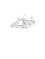
図1は、第1の実施形態のプロジェクター1Aの設置状態を示す斜視図である。
本実施形態のプロジェクター1Aは、吊り天井構造を有する天井の天井裏(第2の空間)に設置される。
吊り天井構造は、建物の建物躯体(図示略)に、吊りボルト(図示略)を介して複数の野縁3及び複数の野縁受け5と、天井板7とが吊り下げ支持された構造である。天井板7が本発明の仕切面に相当する。
野縁3及び野縁受け5は、細長い棒状の部材であり、本発明の支持部材に相当する。複数の野縁3は、水平の一定方向に所定の間隔をあけて並設され、天井板7を裏側から支持する。複数の野縁受け5は、野縁3に直交する水平な他方向に所定の間隔をあけて並設され、複数の野縁3を支持する。複数の野縁受け5は、下端を複数の野縁3に接続し、上端を上階の建物躯体に固着された複数の吊りボルトにより吊り下げ支持される。また、天井板7は、複数の野縁3の下面にビス留め等により固定される。なお、野縁3及び野縁受け5は、平面視で格子状に配列されるが、図1では、その一部の区画のみを図示している。
[First Embodiment]
FIG. 1 is a perspective view showing an installed state of the projector 1A of the first embodiment.
The projector 1A of the present embodiment is installed behind the ceiling (second space) of a ceiling having a suspended ceiling structure.
The suspended ceiling structure is a structure in which a plurality of
The
プロジェクター1Aは、第1の筐体100Aと、第2の筐体200Aとを備え、第1の筐体100Aと、第2の筐体200Aとは電源ケーブル50により接続される。
第1の筐体100Aは、円筒形状を有し、第1の筐体100Aの内部には、画像をスクリーン等の投写対象に投写する投写部110(図4参照)等が収納される。第2の筐体200Aは、細長い直方体形状を有し、第2の筐体200Aの内部には、投写部110に電源を供給する電源部210(図4参照)が収納される。電源部210は、電源ケーブル50を介して第1の筐体100Aに収納された投写部110等に電源を供給する。
The projector 1A includes a
The
本実施形態は、投写部110を収納した第1の筐体100Aと、電源部210を収納した第2の筐体200Aとを別体で構成し、第2の筐体200Aを支持部材としての野縁受け5に固定した。
従って、第1の筐体100Aの重量を軽量化することができるので、重量制限のある天井板7等にも第1の筐体100Aを設置することができる。このため、天吊具を用いて建物躯体から吊り下げる等の方法を取らなくても、プロジェクター1Aを天井裏に設置することができ、プロジェクター1Aの天井裏等への設置が容易になる。
In the present embodiment, the
Therefore, since the weight of the
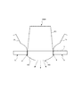
図2は、第1の筐体100Aの設置状態を示す側面図である。
第1の筐体100Aは、天井板7に穿設された天井開口8に嵌め込むように設置される。第1の筐体100Aの一部は、第2の空間である天井裏に配置される。
天井板7は、例えば、木、金属、軽量コンクリート等の板あるいは石膏ボード等の建材である。天井板7には、第1の筐体100Aの一部を挿入可能な天井開口8が形成される。
第1の筐体100Aの外装には、一対の取り付けバネ25が設けられている。一対の取り付けバネ25は、例えば、円柱形状の第1の筐体100Aを挟んで対向するように形成される。取り付けバネ25は、本発明の固定部に相当する。なお、固定部は、第1の筐体100Aを天井板7に固定するものであれば、取り付けバネ25に限定されず、例えば、ネジであってもよい。
FIG. 2 is a side view showing the installation state of the
The
The ceiling board 7 is, for example, a board such as wood, metal, or lightweight concrete, or a building material such as gypsum board. A
A pair of mounting
第1の筐体100Aは、天井開口8に、室内空間(第1の空間)側である天井面71側から差し込まれる。
天井開口8に第1の筐体100Aが差し込まれた状態で、取り付けバネ25は天井開口8を外側に押圧するよう作用し、取り付けバネ25と天井板7とが嵌合する。取り付けバネ25の弾性により、第1の筐体100Aは、天井開口8から落下しないよう保持及び固定される。
第1の筐体100Aが天井板7に設置された設置状態において、天井板7の天井面71側に露出する第1の筐体100Aの部分を突出部102といい、天井板7の上部空間である天井裏に納まる部分を本体部101という。
突出部102には、投写部110が出射する光を通すための投写口103が形成される。投写部110は、投写口103を介して室内空間側に画像光を投写する。
100 A of 1st housing|casings are inserted in the ceiling opening 8 from the
When the
In the installed state where the
The
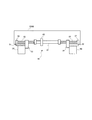
図3は、図1のX−X線における第2の筐体の断面図である。
第2の筐体200Aは、野縁受け5の上に載置され、固定具40により野縁受け5に固定される。第2の筐体200Aは、当該第2の筐体200Aの長手方向が、天井板7と平行で、且つ野縁受け5の長手方向に平行となるように配置される。固定具40は、左右ネジ41と、一対のプレート42とを備える。一対のプレート42は、本発明の挟持部材に相当する。
左右ネジ41は、当該左右ネジ41の中央を境にして左側と右側とで逆向きにネジが切られている。一対のプレート42には、それぞれネジが切られた貫通孔が設けられている。
左右ネジ41を、ネジが切られた一対のプレート42の貫通孔に挿通させ、挿通された左右ネジ41の端部をナット(図示略)により締め付けることにより、一対のプレート42が野縁受け5を挟持し、第2の筐体200Aは、野縁受け5に密着した状態で保持及び固定される。
FIG. 3 is a cross-sectional view of the second housing taken along the line XX of FIG.
The
The left and
By inserting the left and
図4は、第1実施形態のプロジェクター1Aの制御系の機能ブロック図である。
図4には、リモコン9を合わせて図示する。リモコン9は、プロジェクター1Aの一部を構成する。また、リモコン9はプロジェクター1Aとは別の装置と考えることもでき、この場合、プロジェクター1Aとリモコン9によりプロジェクションシステムを構成する。
FIG. 4 is a functional block diagram of a control system of the projector 1A of the first embodiment.
The
プロジェクター1Aは、別体として構成された第1の筐体100Aと第2の筐体200Aとに分離して収納される。第2の筐体200Aに収納された電源部210は、外部の商用交流電源に接続され、所定の直流電圧を生成して、第1の筐体100Aに収容された各部に電源を供給する。
The projector 1A is separately housed in a
次に、第1の筐体100Aに収納されたプロジェクター1Aの構成について説明する。
投写部110は、光源111、光源111が発する光を変調して画像光を生成する光変調装置112、及び光変調装置112が変調した画像光を投写する投写光学系113を備える。
光源111は、ハロゲンランプ、キセノンランプ、超高圧水銀ランプ等のランプ、又は発光ダイオード、レーザー光源等の固体光源で構成される。光源111は、単一の光源が発する光を赤(R)、緑(G)、青(B)の各色光に分離する分離光学系を備えてもよい。光源111は、後述する光源駆動部121から供給される電力により点灯し、光変調装置112に向けて光を発する。
Next, the configuration of the projector 1A housed in the
The
The
光変調装置112は、光源111が発する光を変調して画像光を生成し、画像光を投写光学系113に照射する。光変調装置112には、透過型の液晶パネルや、反射型の液晶ライトバルブ、デジタルミラーデバイス(DMD)等の光変調素子により構成することができる。光変調装置112の光変調素子には、光変調装置駆動部122が接続される。光変調装置駆動部122は、画像処理部132が出力する画像信号に基づき、光変調素子を駆動して各画素の階調を設定し、光変調素子にフレーム(画面)単位で画像を描画する。
The
投写光学系113は、レンズやミラー等を備え、光変調装置112で変調された画像光を発散又は収束させて、投写する。投写光学系113により、プロジェクター1Aは、壁面、床面、又はスクリーン上に画像を結像させることができる。投写光学系113は、単一のレンズやミラーに限らず、複数のレンズで構成されるレンズ群であってもよい。また、投写光学系113は、ズームレンズ、フォーカスレンズ等を含んでもよい。
The projection
投写光学系113は、画像光の投写方向を変更する投写方向変更部115を備えてもよい。投写方向変更部115は、投写光学系113により投写される画像光を受ける位置に配置された光路変更素子(例えば、ミラー)を備える。光路変更素子は、プロジェクター1Aに着脱可能な構成である。
投写光学系113により投写される画像光をスクリーンや、壁面に投写する場合、投写光学系113により投写される画像光を光路変更素子で反射させ、画像光の進行方向を変更して、スクリーンや壁面に投写する。
投写光学系113及び後述する入力部165は、例えば、天井板7の天井面71側に露出する第1の筐体100Aの部分である突出部102に収納される。また、突出部102には、投写光学系113の投写方向変更部115と、入力部165とを収納した構成であってもよいし、投写方向変更部115だけを収納した構成であってもよい。
The projection
When the image light projected by the projection
The projection
また、プロジェクター1Aは、画像データを出力する画像供給装置2を接続するインターフェイス(以下、I/Fと表記する)部131を備える。画像供給装置2は、例えば、パーソナルコンピューター等の情報処理装置、DVDプレーヤー等の画像再生装置、デジタルテレビチューナー等の放送受信装置、ビデオゲーム機やパーソナルコンピューター等の画像出力装置が挙げられる。画像供給装置2は、パーソナルコンピューター等と通信して画像データを受信する通信装置等であってもよい。
図4には、画像供給装置2をプロジェクター1Aと共に示すが、例えば、画像供給装置2は、第1の空間である室内空間に設置され、プロジェクター1Aは、第2の空間である天井裏に設置される。
Further, the projector 1A includes an interface (hereinafter referred to as I/F)
FIG. 4 shows the image supply device 2 together with the projector 1A. For example, the image supply device 2 is installed in an indoor space which is a first space, and the projector 1A is installed in a ceiling space which is a second space. To be done.
I/F部131は、無線LAN(WiFi(登録商標))や、Miracast(登録商標)、Bluetooth(登録商標)等の無線通信の規格に準じた無線データ通信を、画像供給装置2との間で実行する構成とすることができる。また、I/F部131は、画像供給装置2に有線接続される構成であってもよく、この場合、I/F部131はコネクター及びインターフェイス回路を備える。また、I/F部131は、SD(Secure Digital)メモリーカード等のカード型記録媒体や、USBメモリーデバイス等、可搬型の記憶媒体を接続可能なコネクター及びインターフェイス回路を備えてもよい。
The I/
プロジェクター1Aは、プロジェクター1Aの各部を制御する制御部150を備える。制御部150は、プロジェクター1Aの各部を制御することにより、I/F部131に入力される画像データに基づく画像を投写部110によって表示(投写)する。
The projector 1A includes a
I/F部131には、画像データを処理して表示用の画像信号を投写部110に出力する画像処理部132が接続される。画像処理部132は、画像供給装置2からI/F部131に入力される画像データを取得し、取得した画像データに対する画像処理を実行する。また、画像処理部132は、I/F部131に可搬型の記憶媒体が接続された場合に、この記憶媒体から画像データを読み出して取得し、画像供給装置2から入力される画像データと同様に処理してもよい。
An
制御部150は、例えば、図示しないCPU、ROM、及びRAMを備え、ROM或いは後述する記憶部155が記憶するプログラムをCPUが実行することにより、プロジェクター1Aの各部を制御する。
制御部150には、記憶部155、画像処理部132、光源駆動部121、光変調装置駆動部122及び入力部165が接続される。制御部150は、これらの各部を制御する機能ブロックとして、投写制御部151を有する。投写制御部151は、制御部150のCPUがプログラムを実行することにより、ソフトウェアとハードウェアの協働により実現される機能ブロックである。
The
The
記憶部155は、フラッシュメモリー等の不揮発性記憶装置により構成され、制御部150により処理されるデータや、制御部150のCPUが実行するプログラムを記憶する。また、記憶部155は、プロジェクター1Aが投写する画像データを記憶してもよい。
The
画像処理部132は、I/F部131に接続され、I/F部131に入力される画像データを取得する。画像処理部132は、制御部150の制御に従って、取得した画像データに対して各種処理を行う。例えば、画像処理部132は、画像データの解像度を光変調装置112の表示解像度に合わせて変換する解像度変換処理を実行する。また、画像処理部132は、画像データの形状を補正する幾何補正処理、画像データの色調を補正する色調補正処理等を実行する。画像処理部132は、処理後の画像データを表示するための画像信号を生成し、光変調装置駆動部122に出力する。
また、画像処理部132は、記憶部155が画像データを記憶する場合、記憶部155が記憶する画像データに対して上記画像処理を行ってもよい。この場合、制御部150が記憶部155から画像データを読み出して画像処理部132に出力する。画像処理部132は画像データに対する処理を行って、画像信号を光変調装置駆動部122に出力する。
The
Further, when the
光源駆動部121は、光源111に対して駆動電流やパルスを供給し、光源111を発光させる。また、光源駆動部121は光源111の発光の輝度を調整可能であってもよい。
光変調装置駆動部122は、制御部150の制御に従って、画像処理部132から入力される画像信号に基づき、光変調装置112を駆動して、光変調装置112にフレーム単位で画像を描画する。
The light
The light modulation
投写制御部151は、投写部110を制御して画像を投写させる。
また、投写制御部151は、画像処理部132が実行する処理の実行タイミング、実行条件等を制御する。さらに、投写制御部151は、光源駆動部121を制御して、光源111の輝度の調整等を行う。また、投写制御部151は、光変調装置駆動部122が光変調装置112に画像を描画する処理を制御する。
The
Further, the
また、制御部150は、入力部165に接続される。入力部165は、リモコン受光部として機能し、リモコン9が送信する赤外線信号を受信して、リモコン9における操作を示す操作信号を制御部150に出力する。制御部150は、入力部165から入力される操作信号に基づき、画像を投写する指示を検出した場合に、I/F部131に入力される画像データや記憶部155が記憶する画像データに基づいて投写を実行する。また、制御部150は、入力部165から入力される操作信号に基づき、投写終了の指示を検出した場合に、投写を終了する。
The
以上説明したように、本発明を適用した第1実施形態のプロジェクター1Aは、投写部110を収納する第1の筐体100Aと、電源部210を収容する第2の筐体200Aと、を備える。第2の筐体200Aは、空間を天井裏と居室空間とに仕切る天井板7を支持する支持部材としての野縁受け5に固定される。投写部110を収納する第1の筐体100Aと、電源部210を収容する第2の筐体200Aとは、別体として構成される。
従って、投写部110を収納した第1の筐体100Aを軽量化することができ、天井板7等の空間を仕切る仕切面に第1の筐体100Aを容易に設置することができる。
As described above, the projector 1A according to the first embodiment to which the present invention is applied includes the
Therefore, it is possible to reduce the weight of the
また、投写部110は、第1の筐体100Aに形成された投写口103を、天井板7に設けられた天井開口8から露出させ、天井板7により仕切られた居室空間に画像光を投写する。従って、天井板7に設けられた天井開口8から第1の筐体100Aの投写口103を露出させ、居室空間に画像光を投写することができる。
In addition, the
また、第2の筐体200Aは、野縁受け5を両側から挟持する一対のプレート42により野縁受け5に固定される。従って、簡易な構成で、第2の筐体200Aを野縁受け5に固定することができる。
The
また、第1の筐体100Aは、投写口103が天井開口8から露出した状態において、天井板7を押圧して第1の筐体100Aを天井板7に固定する取り付けバネ25を備える。従って、簡易な構成で、第1の筐体100Aを天井板7に固定することができる。
Further, the
[第2実施形態]
図5は、第2実施形態のプロジェクター1Bの設置状態を示す斜視図である。
本実施形態において、上述した第1実施形態で説明したプロジェクター1Aと共通の構成については、同一の符号を付しその説明を省略する。
[Second Embodiment]
FIG. 5 is a perspective view showing an installed state of the
In this embodiment, the same components as those of the projector 1A described in the first embodiment described above are designated by the same reference numerals, and the description thereof will be omitted.
第1実施形態と同様、第2実施形態の第1の筐体100Bは、円筒形状を有し、第2の筐体200Bは、細長い直方体形状を有している。また、第2の筐体200Bには電源部210が収納されており、電源部210は、電源ケーブル50を介して第1の筐体100Bに収納された投写部110等に電源を供給する。
Similar to the first embodiment, the
第2実施形態の第2の筐体200Bは、隣接する2つの野縁受け5をまたいで設置されている。すなわち、第2の筐体200Bは、その長手方向が天井板7に平行ではあるが、野縁受け5に平行な方向ではなく、野縁3に平行な方向に配置される。また、第2の筐体200Bは、またがった野縁受け5のそれぞれに固定される。第2の筐体200Bが固定される野縁受け5を、野縁受け5A、5Bと表記する。図5に示すように、野縁受け5Aが紙面に向かって左側に位置し、野縁受け5Bが紙面に向かって右側に位置する。
さらに、第2実施形態では、第1の筐体100Bは、第2の筐体200Bに固定される。第2の筐体200Bに固定された状態で、第1の筐体100Bは、その長手方向が天井板7に垂直になるような姿勢となる。
The
Furthermore, in the second embodiment, the
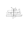
図6は、図5のQ−Q線における第2の筐体200Bの断面図である。
第2の筐体200Bは、固定具60によって野縁受け5A及び5Bに固定される。固定具60は、ネジ軸61、第1プレート53、第2プレート54、軸受け66、67を備える。
ネジ軸61は、中央部にネジ軸61を回転させるための操作部65が形成され、操作部65を境にして左側と右側とで逆向きにネジが切られている。ネジ軸61の左側に形成されたネジ部分を左ネジ部62といい、ネジ軸61の右側に形成されたネジ部分を右ネジ部63という。
ネジ軸61の両端部は、第2の筐体200Bに固定された軸受け66、67によってそれぞれ支持されている。
FIG. 6 is a cross-sectional view of the
The
The
Both ends of the
第1及び第2プレート53、54には、貫通孔が形成され、貫通孔の表面にはネジが形成されている。第1プレート53は、ネジ軸61の左ネジ部62に螺合し、第2プレート54は、ネジ軸61の右ネジ部63に螺合する。
第1及び第2プレート53、54には、外側に突出するように台座部51、52が固定されており、第2の筐体200Bは、台座部51、52が野縁受け5A、5Bの上に載置されるように設置される。
第1プレート53は、隣接する野縁受け5Aと野縁受け5Bの間に配置され、野縁受け5Aと野縁受け5Bとの対向面のうち、野縁受け5Aの対向面に接するように配置される。
第2プレート54は、隣接する野縁受け5Aと野縁受け5Bの間に配置され、野縁受け5Aと野縁受け5Bとの対向面のうち、野縁受け5Bの対向面に接するように配置される。
操作部65を操作してネジ軸61を所定方向に回転させると、ネジ軸61の左ネジ部62に螺合した第1プレート53が、野縁受け5Aを外側(野縁受け5Bの方向とは反対側)に押圧するとともに、ネジ軸61の右ネジ部63に螺合した第2プレート54が野縁受け5Bを外側(野縁受け5Aの方向とは反対側)に押圧する。
第1プレート53及び第2プレート54がそれぞれ外側に押圧されることで、第2の筐体200Bが野縁受け5A、5Bに保持及び固定される。
Through holes are formed in the first and
The
The
The
When the
By pressing the
次に、第1の筐体100Bの第2の筐体200Bへの固定方法について説明する。
第1の筐体100Bは、第2の筐体200Bに固定される。第1の筐体100Bを固定する第2の筐体200Bの位置を変更することができる。第2の筐体200Bは、第1の筐体100Bを、第2の筐体200Bの長手方向の異なる位置で固定することができる。
また、第2の筐体200Bに固定される第1の筐体100Bの位置を変更することができる。第1の筐体100Bは、第2の筐体200Bに固定される位置を、第1の筐体100Bの長手方向で変更することができる。
Next, a method of fixing the
The
Further, the position of the
図7は、第2の筐体200Bを示す斜視図である。
第2の筐体200Bには、2つのボルト保持部201、202が形成されている。これらのボルト保持部201、202には、後述するボルト81が挿通される孔がそれぞれに形成されている。ボルト保持部201、202の少なくとも一方は、孔の表面にネジが切られており、雌ねじを構成する。
また、ボルト保持部201、202は、第2の筐体200Bに着脱自在に取り付けられ、取り付け位置を、第2の筐体200Bの長手方向で変更することができる。この構成により、第2の筐体200Bは、第1の筐体100Bを、第2の筐体200Bの長手方向の異なる位置で固定することができる。
なお、ボルト保持部201、202を着脱自在な構成とする代わりに、第2の筐体200Bの長手方向に沿ってボルト保持部201、202をスライドさせる構成としてもよい。また、図7には、2つのボルト保持部201、202を示したが、ボルト保持部201、202の数は2つに限定されない。
FIG. 7 is a perspective view showing the
Two
Further, the
Instead of the detachable structure of the
図8は、第1の筐体100Bを示す斜視図である。
第1の筐体100Bの側面には、長手方向に沿って溝84が形成されており、溝84の両端には、ボルト保持部82、83が形成されている。ボルト保持部82、83の間には、第2の筐体200Bのボルト保持部201、202(図8では図示略)に挿通された状態のボルト81が配置される。
ボルト保持部82、83は、ボルト81を回転可能に保持する。プロジェクター1Bを天井に設置した状態において、ボルト81は、その軸方向が天井板7に垂直になるように保持される。ボルト保持部82、83の少なくとも一方は、ボルト81を回転操作させる操作機構(図示略)と、回転操作が完了した後のボルト81の回転を規制するロック機構(図示略)とを有している。
FIG. 8 is a perspective view showing the
A
The
図9は、第2実施形態のプロジェクター1Bの設置状態を示す上面図である。
また、図10は、第1の筐体100Bを第2の筐体200Bに固定した状態を示す図である。
まず、第2の筐体200Bの長手方向におけるボルト保持部201、202の取り付け位置を調整する。すなわち、第2の筐体200Bが野縁受け5A、5Bに固定された状態において、天井板7に穿設された天井開口8に、第1の筐体100Bの突出部102が露出するように、ボルト保持部201、202の取り付け位置を調整する。
FIG. 9 is a top view showing an installed state of the
Further, FIG. 10 is a diagram showing a state in which the
First, the attachment positions of the
次に、ボルト81の雄ネジと、第2の筐体200Bのボルト保持部201、202に形成された雌ネジとが螺合した状態で、ボルト81を回転させると、第1の筐体100Bが第2の筐体200Bに対してボルト81の軸方向に沿って移動する。つまり、ボルト81を回転させることで、第2の筐体200Bに固定される第1の筐体100Bの位置を、第1の筐体100Bの長手方向で変更することができる。これにより、例えば、野縁受け5A、5Bの高さが異なる場合であっても、第1の筐体100Bの突出部102を、天井開口8から露出させ、投写口から画像光を射出することができる。
Next, when the
以上説明したように、本発明を適用した第2実施形態のプロジェクター1Bによれば、上述した第1実施形態のプロジェクター1Aが有する効果に加えて、以下の効果を得られる。
第2実施形態のプロジェクター1Bは、第1の筐体100Bが、第2の筐体200Bに固定される。また、第1の筐体100Bが固定される第2の筐体200Bの位置を、第2の筐体200Bの長手方向(天井板7に平行な方向)で変更可能である。従って、プロジェクター1Bの設置環境に応じて、第1の筐体100Bの設置位置を変更することができる。
As described above, according to the
In the
また、第2の筐体200Bに固定される第1の筐体100Bの位置を、第1の筐体100Bの長手方向(天井板7に垂直な方向)で変更可能である。従って、プロジェクター1Bの設置環境に応じて、第2の筐体200Bに固定される第1の筐体100Bの位置を変更することができる。
Further, the position of the
なお、上述した各実施形態は、あくまでも本発明の一態様を示すものであり、本発明の範囲内で任意に変形及び応用が可能である。
例えば、プロジェクター1A、1Bの細部構成は任意であり、第1の筐体100A、100B、及び第2の筐体200A、200Bに収納するプロジェクター1A、1Bの構成を変更することもできる。
例えば、図4に示す投写部110以外の構成を、第2の筐体200A、200Bに収納するように構成してもよい。また、投写部110、光源駆動部121、光変調装置駆動部122、I/F部131、画像処理部132、入力部165等を第1の筐体100A、100Bに収納し、電源部210、制御部150、記憶部155を第2の筐体200A、200Bに収納してもよい。
また、例えば、リモコン9が送信する無線信号を受信するアンテナや受光部を、第2の筐体200A、200Bに配置してもよい。
It should be noted that the above-described respective embodiments merely show one aspect of the present invention, and can be arbitrarily modified and applied within the scope of the present invention.
For example, the detailed configurations of the
For example, a configuration other than the
Further, for example, an antenna or a light receiving unit that receives a radio signal transmitted by the
また、上記実施形態では、第1の筐体100A、100Bの一部(突出部102)が天井板7から室内空間側に突出した構成について説明したが、第1の筐体100A、100Bの全体が天井裏に配置される構成とすることも可能である。また、上記実施形態では、第2の筐体200A、200Bを野縁受け5に固定しているが、野縁3に固定するようにしてもよい。
Further, in the above-described embodiment, the configuration in which a part (projection portion 102) of the
また、上記実施形態では、プロジェクター1A、1Bを天井裏に設置する例を示したが、プロジェクター1A、1Bは、壁面や床面に埋設設置することもでき、家具や什器に埋設設置してもよい。また、屋外に設置することも可能である。
Further, in the above-described embodiment, an example in which the
また、上記各実施形態において、リモコン9は、プロジェクター1A、1Bに対して使用される専用の装置に限定されない。リモコン9は、赤外線信号、又はWiFiやBluetoothによる無線信号によって、プロジェクター1A、1Bに対して操作信号を送信できればよい。また、プロジェクター1A、1Bにおいて、入力部165は、リモコン9が送信する信号を受信できればよく、信号のフォーマットや物理的要件は任意に変更できる。従って、例えばリモコン9として、スマートフォンやタブレット型コンピューターを用いる構成としてもよい。スマートフォンやタブレット型コンピューターに、プロジェクター1A、1Bを操作するためのアプリケーションプログラムをインストールすることで、リモコン9として機能する構成とすることができる。この構成によれば、汎用的なスマートフォンやタブレット型コンピューターをリモコン9として利用できる。また、リモコン9として機能するスマートフォンやタブレット型コンピューターが、画像供給装置2としても機能する構成も勿論実現可能である。
Further, in each of the above embodiments, the
また、図4に示した各機能ブロックはハードウェアとソフトウェアとの協働により実現される機能的構成を示すものであって、具体的な実装形態は特に制限されない。従って、必ずしも各機能ブロックに対応するハードウェアが実装される必要はなく、一つのプロセッサーがプログラムを実行することで複数の機能部の機能を実現する構成とすることも勿論可能である。また、上記実施形態においてソフトウェアで実現される機能の一部をハードウェアで実現してもよく、あるいは、ハードウェアで実現される機能の一部をソフトウェアで実現してもよい。その他、プロジェクター1A、1Bの他の各部の具体的な細部構成についても、本発明の趣旨を逸脱しない範囲で任意に変更可能である。
Further, each functional block shown in FIG. 4 shows a functional configuration realized by cooperation of hardware and software, and a specific implementation form is not particularly limited. Therefore, hardware corresponding to each functional block does not necessarily have to be mounted, and one processor may of course be configured to realize the functions of a plurality of functional units by executing a program. Further, in the above embodiment, some of the functions realized by software may be realized by hardware, or some of the functions realized by hardware may be realized by software. In addition, the specific detailed configurations of other parts of the
1A、1B…プロジェクター、2…画像供給装置、3…野縁(支持部材)、5…野縁受け(支持部材)、7…天井板、8…天井開口、9…リモコン、25…取り付けバネ(固定部)、40…固定具、41…左右ネジ、42…プレート(挟持部材)、50…電源ケーブル、51、52…台座部材、53…第1プレート、54…第2プレート、60…固定具、61…ネジ軸、62…左ネジ部、63…右ネジ部、65…操作部、66、67…軸受け、71…天井面、81…ボルト、82、83…ボルト保持部、84…溝、100A、100B…第1の筐体、102…突出部、103…投写口、110…投写部、111…光源、112…光変調装置、113…投写光学系、115…投写方向変更部、121…光源駆動部、122…光変調装置駆動部、131…I/F部、132…画像処理部、150…制御部、151…投写制御部、155…記憶部、165…入力部、200A、200B…第2の筐体、201、202…ボルト保持部、210…電源部。 1A, 1B... Projector, 2... Image supply device, 3... Field edge (supporting member), 5... Field edge receiving (supporting member), 7... Ceiling plate, 8... Ceiling opening, 9... Remote control, 25... Mounting spring ( Fixing part), 40... Fixing device, 41... Left and right screws, 42... Plate (holding member), 50... Power cable, 51, 52... Pedestal member, 53... First plate, 54... Second plate, 60... Fixing device , 61... screw shaft, 62... left screw part, 63... right screw part, 65... operation part, 66, 67... bearing, 71... ceiling surface, 81... bolt, 82, 83... bolt holding part, 84... groove, 100A, 100B... 1st housing, 102... Projection part, 103... Projection opening, 110... Projection part, 111... Light source, 112... Light modulation device, 113... Projection optical system, 115... Projection direction change part, 121... Light source drive section, 122... Light modulation device drive section, 131... I/F section, 132... Image processing section, 150... Control section, 151... Projection control section, 155... Storage section, 165... Input section, 200A, 200B... 2nd housing|casing, 201,202... Bolt holding|maintenance part, 210... Power supply part.
Claims (4)
前記投写部に電源を供給する電源部と、
前記投写部を収納する第1の筐体と、
前記電源部を収容する第2の筐体と、を備え、
前記第2の筐体は、空間を第1の空間と第2の空間とに仕切る天井板を支持する支持部材に固定され、
前記第1の筐体は、前記第2の空間側に配置され、一部が、前記天井板に形成された天井開口を介して前記第1の空間側に露出した状態で前記天井板に固定され、
前記第1の筐体と前記第2の筐体とは、別体として構成される、ことを特徴とするプロジェクター。 A projection unit for projecting image light,
A power supply unit for supplying power to the projection unit,
A first housing for housing the projection unit;
A second housing that houses the power supply unit;
The second housing is fixed to a support member that supports a ceiling plate that divides the space into a first space and a second space,
The first housing is arranged on the side of the second space, and is fixed to the ceiling plate while a part of the first casing is exposed to the side of the first space through a ceiling opening formed in the ceiling plate. Was
The projector, wherein the first housing and the second housing are configured as separate bodies.
前記第1の筐体の前記一部は、前記投写部の投写口を含み、
前記投写部は、前記投写口を前記天井開口から露出させ、前記第1の空間に画像光を投写する、ことを特徴とする請求項1記載のプロジェクター。 Before Stories second housing is disposed in the second space,
The part of the first housing includes a projection opening of the projection unit,
The projection portion, before the Kito Utsushiguchi exposed from the ceiling opening, the projector according to claim 1, wherein said projecting an image light to the first space, characterized in that.
前記投写部に電源を供給する電源部と、
前記投写部を収納する第1の筐体と、
前記電源部を収容する第2の筐体と、を備え、
前記第2の筐体は、空間を第1の空間と第2の空間とに仕切る仕切面を支持する支持部材に固定され、
前記第2の筐体は、前記支持部材を両側から挟持する一対の挟持部材により前記支持部材に固定され、
前記第1の筐体と前記第2の筐体とは、別体として構成される、ことを特徴とするプロジェクター。 A projection unit for projecting image light,
A power supply unit for supplying power to the projection unit,
A first housing for housing the projection unit;
A second housing that houses the power supply unit;
The second housing is fixed to a support member that supports a partition surface that divides the space into a first space and a second space,
The second housing is fixed to the support member by a pair of sandwiching members that sandwich the support member from both sides,
The projector, wherein the first housing and the second housing are configured as separate bodies.
Priority Applications (3)
| Application Number | Priority Date | Filing Date | Title |
|---|---|---|---|
| JP2016064222A JP6701873B2 (en) | 2016-03-28 | 2016-03-28 | projector |
| US15/451,710 US10771750B2 (en) | 2016-03-28 | 2017-03-07 | Projector |
| CN201710169435.2A CN107238998B (en) | 2016-03-28 | 2017-03-21 | Projector with a light source |
Applications Claiming Priority (1)
| Application Number | Priority Date | Filing Date | Title |
|---|---|---|---|
| JP2016064222A JP6701873B2 (en) | 2016-03-28 | 2016-03-28 | projector |
Publications (3)
| Publication Number | Publication Date |
|---|---|
| JP2017181566A JP2017181566A (en) | 2017-10-05 |
| JP2017181566A5 JP2017181566A5 (en) | 2019-04-18 |
| JP6701873B2 true JP6701873B2 (en) | 2020-05-27 |
Family
ID=59898316
Family Applications (1)
| Application Number | Title | Priority Date | Filing Date |
|---|---|---|---|
| JP2016064222A Active JP6701873B2 (en) | 2016-03-28 | 2016-03-28 | projector |
Country Status (3)
| Country | Link |
|---|---|
| US (1) | US10771750B2 (en) |
| JP (1) | JP6701873B2 (en) |
| CN (1) | CN107238998B (en) |
Families Citing this family (3)
| Publication number | Priority date | Publication date | Assignee | Title |
|---|---|---|---|---|
| JP6682941B2 (en) * | 2016-03-24 | 2020-04-15 | セイコーエプソン株式会社 | projector |
| JP7026877B2 (en) * | 2019-03-18 | 2022-03-01 | 株式会社Esc | Antenna mounting device |
| JP7352882B2 (en) * | 2019-10-31 | 2023-09-29 | パナソニックIpマネジメント株式会社 | projector |
Family Cites Families (29)
| Publication number | Priority date | Publication date | Assignee | Title |
|---|---|---|---|---|
| JPH046585A (en) * | 1990-04-24 | 1992-01-10 | Matsushita Electric Ind Co Ltd | Video projecting device |
| JP2581757Y2 (en) * | 1991-04-26 | 1998-09-24 | ミサワホーム株式会社 | Video projector projection equipment |
| CN1119746A (en) * | 1994-09-29 | 1996-04-03 | 北京市西城区新开通用试验厂 | Attracted top projector display device for industry control |
| US7631848B2 (en) * | 2001-06-08 | 2009-12-15 | Draper, Inc. | Projector lift |
| US6637711B2 (en) * | 2001-06-08 | 2003-10-28 | Draper, Inc. | Projector lift |
| JP2004233692A (en) * | 2003-01-30 | 2004-08-19 | Dainippon Printing Co Ltd | Projector device |
| AU2004292334B2 (en) * | 2003-11-25 | 2010-12-23 | Hills Limited | Apparatus for concealing a product |
| NZ548039A (en) * | 2003-11-25 | 2010-04-30 | Herma Technologies Pty Ltd | Apparatus for concealing a product such as a video projector by moving a hinged panel |
| US20080192226A1 (en) * | 2004-06-07 | 2008-08-14 | Nikon Corporation | Stage Unit, Exposure Apparatus, and Exposure Method |
| JP2006349790A (en) * | 2005-06-14 | 2006-12-28 | Seiko Epson Corp | Air bag apparatus, and electronic device and projector equipped with same, |
| JP5168834B2 (en) * | 2005-09-14 | 2013-03-27 | ソニー株式会社 | Audiovisual system |
| JP5140399B2 (en) | 2007-07-26 | 2013-02-06 | 三洋電機株式会社 | Projection display device |
| JP2009145526A (en) * | 2007-12-13 | 2009-07-02 | Seiko Epson Corp | Projector and image display system |
| WO2010044204A1 (en) * | 2008-10-15 | 2010-04-22 | パナソニック株式会社 | Light projection device |
| JP2010164685A (en) * | 2009-01-14 | 2010-07-29 | Seiko Epson Corp | Projection type display device and projection type display facility |
| DE102010018896A1 (en) * | 2010-04-30 | 2011-11-03 | Airbus Operations Gmbh | Passenger supply arrangement for an airplane |
| JP5646266B2 (en) * | 2010-09-29 | 2014-12-24 | 三洋電機株式会社 | projector |
| JP2013142845A (en) * | 2012-01-12 | 2013-07-22 | Nikon Corp | Electronic device |
| US9134592B2 (en) * | 2012-04-06 | 2015-09-15 | Seiko Epson Corporation | Ceiling hanger |
| US9268203B1 (en) * | 2012-06-01 | 2016-02-23 | Amazon Technologies, Inc. | Magnetically coupling a system to a surface |
| US9316889B2 (en) * | 2012-08-07 | 2016-04-19 | Nook Digital, Llc | Front projection eReader system |
| WO2014171147A1 (en) * | 2013-04-18 | 2014-10-23 | パナソニック株式会社 | Projection type image display device |
| US9405176B2 (en) * | 2013-07-19 | 2016-08-02 | Seiko Epson Corporation | Projector with adjustable support |
| JP6322916B2 (en) * | 2013-07-19 | 2018-05-16 | セイコーエプソン株式会社 | projector |
| JP5637469B1 (en) * | 2013-10-02 | 2014-12-10 | 株式会社リコー | Image projection device |
| CN203658715U (en) * | 2013-11-21 | 2014-06-18 | 徐峻峰 | Projector and projection system |
| JP6369051B2 (en) * | 2014-02-27 | 2018-08-08 | セイコーエプソン株式会社 | projector |
| CN205101814U (en) * | 2015-05-27 | 2016-03-23 | 刘立仁 | Projection arrangement and gallows thereof |
| GB2544543B (en) * | 2015-11-20 | 2020-10-07 | Zuma Array Ltd | Lighting and sound system |
-
2016
- 2016-03-28 JP JP2016064222A patent/JP6701873B2/en active Active
-
2017
- 2017-03-07 US US15/451,710 patent/US10771750B2/en active Active
- 2017-03-21 CN CN201710169435.2A patent/CN107238998B/en active Active
Also Published As
| Publication number | Publication date |
|---|---|
| CN107238998A (en) | 2017-10-10 |
| US20170280116A1 (en) | 2017-09-28 |
| CN107238998B (en) | 2021-07-09 |
| JP2017181566A (en) | 2017-10-05 |
| US10771750B2 (en) | 2020-09-08 |
Similar Documents
| Publication | Publication Date | Title |
|---|---|---|
| JP6682941B2 (en) | projector | |
| JP6701873B2 (en) | projector | |
| US20150022788A1 (en) | Projector and method of controlling projector | |
| CN104298054A (en) | Projector | |
| US9618825B2 (en) | Projector and method for controlling projector with changing content | |
| WO2019058521A1 (en) | Projector and projector system | |
| US9338415B2 (en) | Projector and image display apparatus | |
| JP6322917B2 (en) | projector | |
| JP5646266B2 (en) | projector | |
| JP6450959B2 (en) | projector | |
| CN110764340B (en) | Projector and projection system | |
| US11531255B2 (en) | Projector, projection optical device, and method of controlling projector | |
| JP2016086249A (en) | Display unit, display control method and display control program | |
| JP6369090B2 (en) | Mounting base | |
| CN108668119B (en) | Display device, display system, and control method for display device | |
| WO2015133104A1 (en) | Projector and projector control method | |
| JP6268889B2 (en) | Lighting device | |
| JP2011035798A (en) | Projection type video display device | |
| JP2011007940A (en) | Projection display apparatus | |
| JP5070095B2 (en) | Projection-type image display device and projection-type image display system using the same | |
| JP2022059236A (en) | Projection system and furniture | |
| CN112752078A (en) | Operation device, image projection system, operation method, and recording medium | |
| JP2015028516A (en) | Light projection device, and method of using light projection device | |
| JP2015158545A (en) | Image projecting device and specification method |
Legal Events
| Date | Code | Title | Description |
|---|---|---|---|
| A521 | Request for written amendment filed |
Free format text: JAPANESE INTERMEDIATE CODE: A523 Effective date: 20190306 |
|
| A621 | Written request for application examination |
Free format text: JAPANESE INTERMEDIATE CODE: A621 Effective date: 20190306 |
|
| A977 | Report on retrieval |
Free format text: JAPANESE INTERMEDIATE CODE: A971007 Effective date: 20191213 |
|
| A131 | Notification of reasons for refusal |
Free format text: JAPANESE INTERMEDIATE CODE: A131 Effective date: 20200128 |
|
| A521 | Request for written amendment filed |
Free format text: JAPANESE INTERMEDIATE CODE: A523 Effective date: 20200330 |
|
| TRDD | Decision of grant or rejection written | ||
| A01 | Written decision to grant a patent or to grant a registration (utility model) |
Free format text: JAPANESE INTERMEDIATE CODE: A01 Effective date: 20200407 |
|
| A61 | First payment of annual fees (during grant procedure) |
Free format text: JAPANESE INTERMEDIATE CODE: A61 Effective date: 20200420 |
|
| R150 | Certificate of patent or registration of utility model |
Ref document number: 6701873 Country of ref document: JP Free format text: JAPANESE INTERMEDIATE CODE: R150 |