JP6701512B2 - Imaging device, imaging method, and program - Google Patents
Imaging device, imaging method, and program Download PDFInfo
- Publication number
- JP6701512B2 JP6701512B2 JP2015539109A JP2015539109A JP6701512B2 JP 6701512 B2 JP6701512 B2 JP 6701512B2 JP 2015539109 A JP2015539109 A JP 2015539109A JP 2015539109 A JP2015539109 A JP 2015539109A JP 6701512 B2 JP6701512 B2 JP 6701512B2
- Authority
- JP
- Japan
- Prior art keywords
- unit
- area
- type
- image
- region
- Prior art date
- Legal status (The legal status is an assumption and is not a legal conclusion. Google has not performed a legal analysis and makes no representation as to the accuracy of the status listed.)
- Active
Links
Images


Classifications
-
- H—ELECTRICITY
- H04—ELECTRIC COMMUNICATION TECHNIQUE
- H04N—PICTORIAL COMMUNICATION, e.g. TELEVISION
- H04N23/00—Cameras or camera modules comprising electronic image sensors; Control thereof
- H04N23/60—Control of cameras or camera modules
- H04N23/67—Focus control based on electronic image sensor signals
- H04N23/675—Focus control based on electronic image sensor signals comprising setting of focusing regions
-
- G—PHYSICS
- G02—OPTICS
- G02B—OPTICAL ELEMENTS, SYSTEMS OR APPARATUS
- G02B7/00—Mountings, adjusting means, or light-tight connections, for optical elements
- G02B7/28—Systems for automatic generation of focusing signals
- G02B7/36—Systems for automatic generation of focusing signals using image sharpness techniques, e.g. image processing techniques for generating autofocus signals
- G02B7/365—Systems for automatic generation of focusing signals using image sharpness techniques, e.g. image processing techniques for generating autofocus signals by analysis of the spatial frequency components of the image
-
- G—PHYSICS
- G03—PHOTOGRAPHY; CINEMATOGRAPHY; ANALOGOUS TECHNIQUES USING WAVES OTHER THAN OPTICAL WAVES; ELECTROGRAPHY; HOLOGRAPHY
- G03B—APPARATUS OR ARRANGEMENTS FOR TAKING PHOTOGRAPHS OR FOR PROJECTING OR VIEWING THEM; APPARATUS OR ARRANGEMENTS EMPLOYING ANALOGOUS TECHNIQUES USING WAVES OTHER THAN OPTICAL WAVES; ACCESSORIES THEREFOR
- G03B13/00—Viewfinders; Focusing aids for cameras; Means for focusing for cameras; Autofocus systems for cameras
- G03B13/32—Means for focusing
- G03B13/34—Power focusing
- G03B13/36—Autofocus systems
-
- G—PHYSICS
- G06—COMPUTING; CALCULATING OR COUNTING
- G06F—ELECTRIC DIGITAL DATA PROCESSING
- G06F18/00—Pattern recognition
- G06F18/20—Analysing
- G06F18/24—Classification techniques
-
- H—ELECTRICITY
- H04—ELECTRIC COMMUNICATION TECHNIQUE
- H04N—PICTORIAL COMMUNICATION, e.g. TELEVISION
- H04N23/00—Cameras or camera modules comprising electronic image sensors; Control thereof
- H04N23/60—Control of cameras or camera modules
- H04N23/61—Control of cameras or camera modules based on recognised objects
- H04N23/611—Control of cameras or camera modules based on recognised objects where the recognised objects include parts of the human body
-
- H—ELECTRICITY
- H04—ELECTRIC COMMUNICATION TECHNIQUE
- H04N—PICTORIAL COMMUNICATION, e.g. TELEVISION
- H04N23/00—Cameras or camera modules comprising electronic image sensors; Control thereof
- H04N23/60—Control of cameras or camera modules
- H04N23/63—Control of cameras or camera modules by using electronic viewfinders
- H04N23/633—Control of cameras or camera modules by using electronic viewfinders for displaying additional information relating to control or operation of the camera
- H04N23/635—Region indicators; Field of view indicators
-
- H—ELECTRICITY
- H04—ELECTRIC COMMUNICATION TECHNIQUE
- H04N—PICTORIAL COMMUNICATION, e.g. TELEVISION
- H04N23/00—Cameras or camera modules comprising electronic image sensors; Control thereof
- H04N23/60—Control of cameras or camera modules
- H04N23/67—Focus control based on electronic image sensor signals
- H04N23/672—Focus control based on electronic image sensor signals based on the phase difference signals
Landscapes
- Engineering & Computer Science (AREA)
- Multimedia (AREA)
- Signal Processing (AREA)
- Physics & Mathematics (AREA)
- General Physics & Mathematics (AREA)
- Computer Vision & Pattern Recognition (AREA)
- Optics & Photonics (AREA)
- Theoretical Computer Science (AREA)
- Data Mining & Analysis (AREA)
- Life Sciences & Earth Sciences (AREA)
- Artificial Intelligence (AREA)
- Bioinformatics & Cheminformatics (AREA)
- Bioinformatics & Computational Biology (AREA)
- Evolutionary Biology (AREA)
- Evolutionary Computation (AREA)
- General Engineering & Computer Science (AREA)
- Studio Devices (AREA)
- Automatic Focus Adjustment (AREA)
- Indication In Cameras, And Counting Of Exposures (AREA)
- Focusing (AREA)
Description
本開示は、撮影装置、撮影方法、およびプログラムに関し、特に、合焦対象とする被写体の種類を撮影ごとに容易に設定することができるようにした撮影装置、撮影方法、およびプログラムに関する。 The present disclosure relates to an image capturing apparatus, an image capturing method, and a program, and particularly relates to an image capturing apparatus, an image capturing method, and a program capable of easily setting the type of a subject to be focused for each image capturing.
撮影装置において、画像内の人物の顔などの特定の被写体を検出し、その被写体にピントを合わせる機能がある(例えば、特許文献1参照)。 The image capturing apparatus has a function of detecting a specific subject such as a person's face in an image and focusing on the subject (for example, see Patent Document 1).
しかしながら、合焦対象とする被写体の種類を撮影ごとに容易に設定することはできなかった。 However, it was not possible to easily set the type of subject to be focused for each shooting.
本開示は、このような状況に鑑みてなされたものであり、合焦対象とする被写体の種類を撮影ごとに容易に設定することができるようにするものである。 The present disclosure has been made in view of such a situation, and makes it possible to easily set the type of subject to be focused for each shooting.
本開示の一側面の撮像装置は、画像を取得する取得部と、前記取得部により取得された前記画像から、合焦対象とする被写体の第1の種類の領域を検出する第1の検出部と、前記画像の撮影単位で、前記被写体の前記第1の種類を選択する第1の選択部とは異なり、前記第1の種類を構成する第2の種類を選択する第2の選択部と、前記第2の選択部により前記第2の種類が選択された場合、前記第1の検出部により検出された前記第1の種類の領域に基づいて、前記第2の種類の領域を検出する第2の検出部と、前記第2の検出部により前記第2の種類の領域が検出された場合、前記2の検出部により検出された前記第2の種類の領域を前記画像の合焦領域として設定する領域設定部とを備え、前記領域設定部は、前記第2の検出部により前記第2の種類の領域が検出されなかった場合、前記第1の検出部により検出された前記第1の種類の領域を前記画像の合焦領域として設定する。 An imaging device according to one aspect of the present disclosure includes an acquisition unit that acquires an image, and a first detection unit that detects a first type region of a subject to be focused from the image acquired by the acquisition unit. And a second selection unit for selecting a second type of the first type, which is different from the first selection unit for selecting the first type of the subject in units of image capturing. If the second type by the second selector is selected, based on the detected first type of regions by the first detection unit detects the second type of region When the second type of area is detected by the second detecting section and the second detecting section, the second type of area detected by the second detecting section is set as the focused area of the image. And a region setting unit configured to set the first region detected by the first detecting unit when the second detecting unit does not detect the region of the second type. The area of the type is set as the focus area of the image .
本開示の一側面の撮影方法およびプログラムは、本開示の一側面の撮影装置に対応する。 An imaging method and a program according to one aspect of the present disclosure correspond to the imaging device according to one aspect of the present disclosure.
本開示の一側面においては、画像が取得され、取得された前記画像から、合焦対象とする被写体の第1の種類の領域が検出され、前記画像の撮影単位で、前記被写体の前記第1の種類を選択する第1の選択部とは異なり、前記第1の種類を構成する第2の種類が第2の選択部で選択され、前記第2の種類が選択された場合、検出された前記第1の種類の領域に基づいて、前記第2の種類の領域が検出される。そして、前記第2の種類の領域が検出された場合、検出された前記第2の種類の領域が前記画像の合焦領域として設定される。また、前記第2の種類の領域が検出されなかった場合、検出された前記第1の種類の領域が前記画像の合焦領域として設定される。 In one aspect of the present disclosure, an image is acquired, a first type region of a subject to be focused is detected from the acquired image, and the first region of the subject is captured in a unit of image capturing of the image. Different from the first selection unit for selecting the type , the second type configuring the first type is selected by the second selection unit, and is detected when the second type is selected. The second type of region is detected based on the first type of region. Then, when the second type area is detected, the detected second type area is set as the focus area of the image. When the second type area is not detected, the detected first type area is set as the focus area of the image.
本開示の一側面によれば、被写体に合焦して撮影することができる。また、本開示の一側面によれば、合焦対象とする被写体の種類を撮影ごとに容易に設定することができる。 According to the embodiments of the present disclosure, it is possible to focus and photograph an object. Further, according to an aspect of the present disclosure, it is possible to easily set the type of subject to be focused for each shooting.
なお、ここに記載された効果は必ずしも限定されるものではなく、本開示中に記載されたいずれかの効果であってもよい。 Note that the effects described here are not necessarily limited, and may be any effects described in the present disclosure.
<第1実施の形態>
(撮影装置の第1実施の形態の外観構成例)
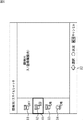
図1乃至図3は、本開示を適用した撮影装置の第1実施の形態の外観構成例を示す図である。図1は、撮影装置の前面図であり、図2は、撮影装置の背面図であり、図3は、撮影装置の上面図である。<First Embodiment>
(External configuration example of the first embodiment of the photographing device)
1 to 3 are diagrams illustrating an external configuration example of a first embodiment of an imaging device to which the present disclosure is applied. 1 is a front view of the photographing apparatus, FIG. 2 is a rear view of the photographing apparatus, and FIG. 3 is a top view of the photographing apparatus.
なお、本明細書において、撮影装置のレンズが配置される面を前面といい、前面と対向する面を背面という。また、前面および背面に垂直な方向を奥行き方向という。 In this specification, the surface on which the lens of the imaging device is arranged is called the front surface, and the surface facing the front surface is called the back surface. Further, the direction perpendicular to the front surface and the back surface is called the depth direction.
図1に示すように、撮影装置10の前面には、被写体から見て右側中央にレンズ10Aが配置される。レンズ10Aは、被写体からの光を集光する。
As shown in FIG. 1, on the front surface of the photographing
また、図1乃至図3に示すように、撮影装置10の上面には、被写体から見て左側にレリーズボタン11が配置される。レリーズボタン11は、撮影を行うときに全押しされる。また、レリーズボタン11は、画像内の既定領域(例えば、画像の中央の領域、奥行き方向の位置が最も撮影装置10に近い被写体の領域など)にピントを合わせる(合焦させる)ときに、半押しされる。レリーズボタン11には、図3に示すように、電源ボタン11Aが付加されている。電源ボタン11Aは、撮影装置10の電源をオンにするときに操作される。
Further, as shown in FIG. 1 to FIG. 3, a
図1乃至図3に示すように、撮影装置10の上面にはまた、被写体から見てレリーズボタン11の右側にモードダイヤル12が配置され、左側にカスタムボタン13が配置される。モードダイヤル12は、撮影モードを選択するときに操作される。カスタムボタン13は、ユーザが所望の機能を割り当て可能なボタンである。
As shown in FIGS. 1 to 3, a
図1および図3に示すように、撮影装置10の前面には、被写体から見てレンズ10Aの左上側に前ダイヤル14が配置される。前ダイヤル14は、例えば、シャッタスピードを調整するときに操作される。
As shown in FIGS. 1 and 3, on the front surface of the photographing
図1に示すように、撮影装置10の前面には、レンズ10Aに隣接してレンズロックボタン15が配置される。レンズロックボタン15は、レンズ10Aを撮影装置10から取り外すときに操作される。
As shown in FIG. 1, a
図2に示すように、撮影装置10の背面には、被写体に向かって左上側にメニューボタン16が配置される。メニューボタン16は、メニュー画面を表示させるときに押下される。
As shown in FIG. 2, a
また、図2に示すように、撮影装置10の背面のメニューボタン16の被写体に向かって右上側には、ファインダ17が配置され、ファインダ17の被写体に向かって右側には、視度調整ダイヤル17Aが配置される。ファインダ17は、撮影時に被写体を確認するための液晶パネルである。
Further, as shown in FIG. 2, a
視度調整ダイヤル17Aは、ファインダ17の度数を調整するときに操作される。ユーザは、ファインダ17に表示される画像が見やすくなるように視度調整ダイヤル17Aを操作する。これにより、ユーザの視力に合った画像がファインダ17に表示される。
The
図2および図3に示すように、撮影装置10の背面のファインダ17の被写体に向かって右下側には、カスタムボタン18が配置され、カスタムボタン18の被写体に向かって右側には後ダイヤル19が配置される。カスタムボタン18は、カスタムボタン13と同様に、ユーザが所望の機能を割り当て可能なボタンである。後ダイヤル19は、例えば、絞り値を調整するときに操作される。
As shown in FIGS. 2 and 3, a
図2に示すように、撮影装置10の背面の後ダイヤル19の被写体に向かって右下側には、録画ボタン20が配置される。録画ボタン20は、動画を撮影するときに押下される。
As shown in FIG. 2, a
また、図2に示すように、撮影装置10の背面のカスタムボタン18の下側には、AELボタン21が配置され、AELボタン21の下側にはFnボタン22が配置される。AELボタン21は、例えば、画面全体の露出を固定するときに押下される。Fnボタン22は、各種の撮影に関する機能を設定する設定画面を表示するときに押下される。
Further, as shown in FIG. 2, an
図2に示すように、撮影装置10の背面のFnボタン22の下には十字キー23が配置される。十字キー23は、上のボタン23A、下のボタン23B、左のボタン23C、右のボタン23D、および中央のボタン23Eにより構成される。十字キー23のボタン23A乃至23Dは、それぞれ、液晶モニタ26に表示されたメニュー画面や設定画面内のカーソル等を上下左右に移動させるときに押下される。
As shown in FIG. 2, a cross key 23 is arranged below the
中央のボタン23Eは、例えば、液晶モニタ26に表示されたメニュー画面や設定画面において決定を指示するときに押下される。また、中央のボタン23Eは、液晶モニタ26にメニュー画面や設定画面が表示されていない状態で、撮影単位の合焦対象とする被写体の種類として瞳を選択するとき、押下される。即ち、液晶モニタ26にメニュー画面や設定画面が表示されていない状態における中央のボタン23Eは、撮影単位で合焦対象とする被写体の種類として瞳を選択する選択部として機能する。
The
図2に示すように、撮影装置10の背面の十字キー23の被写体に向かって左下側には再生ボタン24が配置され、右下側には削除ボタン25が配置される。再生ボタン24は、撮影画像を再生するときに押下される。削除ボタン25は、液晶モニタ26に表示された撮影画像を削除するときに押下される。
As shown in FIG. 2, a
図2に示すように、撮影装置10の背面の被写体に向かって左側には、液晶モニタ26が配置される。液晶モニタ26には、メニュー画面や設定画面、撮影画像等が表示される。
As shown in FIG. 2, a liquid crystal monitor 26 is arranged on the left side of the photographing
(撮影装置のハードウエア構成例)
図4は、撮影装置10のハードウエア構成例を示すブロック図である。(Example of hardware configuration of imaging device)
FIG. 4 is a block diagram showing a hardware configuration example of the
図1の撮影装置10は、光学系41、イメージセンサ42、画像処理部43、圧縮処理部44、メディア制御部45、記録メディア46、およびマイクロコンピュータ47を有する。また、撮影装置10は、合焦制御部48、アクチュエータ49、表示部50、メモリ51、および操作部52を有する。
The photographing
撮影装置10は、液晶モニタ26にメニュー画面や設定画面が表示されていない状態で中央のボタン23Eが押下されたとき、画像内の瞳にピントを合わせる。
When the
具体的には、光学系41とイメージセンサ42は、取得部として機能し、画像を取得する。より詳細には、光学系41は、レンズ10A、図示せぬ絞りなどにより構成される。光学系41は、被写体からの光をイメージセンサ42に集光させる。光学系41は、アクチュエータ49により駆動される。
Specifically, the
イメージセンサ42は、レンズ10Aにより集光された光を画素単位で光電変換し、画像の各画素のアナログ信号である電気信号を取得する。また、イメージセンサ42は、光学系41により集光された光に基づいて、1以上の画素からなる検出単位で、画像の合焦面からのずれ量を表す位相差情報を取得する。イメージセンサ42は、各画素の電気信号を画像処理部43に供給し、位相差情報を合焦制御部48に供給する。
The
画像処理部43は、イメージセンサ42から供給される画像の各画素の電気信号に対してA/D変換等の画像処理を行う。画像処理部43は、その結果得られる画像の各画素のデジタルデータである画像データを、圧縮処理部44とマイクロコンピュータ47に供給する。
The
圧縮処理部44は、必要に応じて、画像処理部43から供給される画像データを圧縮する。圧縮処理部44は、圧縮後の画像データをメディア制御部45に供給する。
The
メディア制御部45は、記録メディア46を制御し、圧縮処理部44から供給される圧縮後の画像データを記録メディア46に記録させる。このように、イメージセンサ42により画像が取得されて圧縮され、圧縮後の画像データが記録される処理を、撮影という。記録メディア46は、メディア制御部45の制御により、圧縮後の画像データを記録する。
The
マイクロコンピュータ47は、撮影装置10の各部を制御する。例えば、マイクロコンピュータ47は、操作部52から供給されるユーザからの操作を表す操作信号に基づいて顔検出モードを設定し、メモリ51に供給して記憶させる。マイクロコンピュータ47は、操作信号に基づいて、表示部50の液晶モニタ26にメニュー画面や設定画面を表示させたり、表示部50に画像処理部43からの画像データに基づく画像を表示させたりする。
The
また、マイクロコンピュータ47は、合焦領域を制御する合焦領域制御部として機能する。具体的には、マイクロコンピュータ47は、画像処理部43から供給される画像データから顔領域を検出する。また、マイクロコンピュータ47は、液晶モニタ26にメニュー画面や設定画面が表示されていないときに操作部52から供給される中央のボタン23Eの押下を表す操作信号と、顔領域とに基づいて、画像データから瞳領域を検出する。マイクロコンピュータ47は、メモリ51に記憶されている顔検出モードと操作信号とに基づいて、顔領域、瞳領域、または既定領域を合焦領域として設定し、その合焦領域を合焦制御部48に供給する。
The
合焦制御部48は、マイクロコンピュータ47から供給される合焦領域と、イメージセンサ42から供給される位相差情報とに基づいて、合焦領域にピントが合うようにアクチュエータ49を制御する。
The
アクチュエータ49は、合焦制御部48等により制御される。アクチュエータ49は、光学系41を駆動し、フォーカス位置、絞り値、およびズーム倍率を制御する。
The
表示部50は、図2のファインダ17と液晶モニタ26により構成される。表示部50は、マイクロコンピュータ47の制御により、撮影画像(圧縮および記録される画像)の画像データに基づいて撮影画像を表示する。また、表示部50は、マイクロコンピュータ47の制御により、撮影画像ではない画像(圧縮および記録されない画像)の画像データに基づく画像を、ライブビュー画像として表示する。表示部50の液晶モニタ26は、マイクロコンピュータ47の制御により、メニュー画面や設定画面を表示する。
The
メモリ51は、マイクロコンピュータ47の作業領域である。メモリ51は、マイクロコンピュータ47による処理の途中結果や最終結果を記憶する。例えば、メモリ51は、マイクロコンピュータ47から供給される顔検出モードを記憶する。
The
操作部52は、レリーズボタン11、電源ボタン11A、モードダイヤル12、カスタムボタン13、前ダイヤル14、メニューボタン16、視度調整ダイヤル17A、およびカスタムボタン18の操作を表す操作信号をマイクロコンピュータ47に供給する。また、操作部52は、後ダイヤル19、録画ボタン20、AELボタン21、Fnボタン22、十字キー23、再生ボタン24、および削除ボタン25の操作を表す操作信号を、マイクロコンピュータ47に供給する。
The
(合焦領域制御部の構成例)
図5は、図4のマイクロコンピュータ47により実現される合焦領域制御部の構成例を示すブロック図である。(Example of configuration of focusing area control unit)
FIG. 5 is a block diagram showing a configuration example of a focusing area control unit realized by the
図5の合焦領域制御部70は、顔検出部71、瞳検出部72、領域設定部73、および表示制御部74により構成される。
The focus
合焦領域制御部70の顔検出部71は、メモリ51から顔検出モードを読み出す。顔検出部71は、顔検出モードに基づいて、画像処理部43から供給される画像データから顔領域を検出する。顔検出部71は、顔領域を瞳検出部72、領域設定部73、および表示制御部74に供給する。
The
瞳検出部72は、メモリ51から顔検出モードを読み出す。瞳検出部72は、液晶モニタ26にメニュー画面や設定画面が表示されていない状態で操作部52から中央のボタン23Eの押下を表す操作信号が供給されたかどうかを判定する。瞳検出部72は、判定結果、顔検出モード、および顔検出部71から供給される顔領域に基づいて、画像データから瞳領域を検出する。瞳検出部72は、瞳領域を領域設定部73に供給する。
The
領域設定部73は、メモリ51から顔検出モードを読み出す。領域設定部73は、顔検出モードと、操作部52から供給されるレリーズボタン11の半押しを表す操作信号とに基づいて、撮影単位で、顔領域、瞳領域、または既定領域を合焦領域として設定する。領域設定部73は、合焦領域を表示制御部74と図4の合焦制御部48に供給する。
The
表示制御部74は、メモリ51から顔検出モードを読み出す。表示制御部74は、顔検出モードに基づいて、顔検出部71から供給される顔領域を表す顔枠を表示中のライブビュー画像に重畳して、表示部50に表示させる。また、表示制御部74は、領域設定部73から供給される合焦領域を表す枠を表示中のライブビュー画像に重畳して、表示部50に表示させる。
The
(顔検出機能の設定画面の例)
図6は、液晶モニタ26に表示される顔検出機能の設定画面の例を示す図である。(Example of setting screen for face detection function)
FIG. 6 is a diagram showing an example of a face detection function setting screen displayed on the
顔検出機能の設定画面は、ユーザによりFnボタン22が押下されたとき表示される。
The face detection function setting screen is displayed when the user presses the
図6に示すように、顔検出機能の設定画面80は、顔検出モードとして顔領域にピントを合わせない顔検出オフモードを選択するときに操作される顔検出オフモードボタン81を含む。
As shown in FIG. 6, the face detection
設定画面80は、顔検出モードとして、予め登録されている顔画像である登録顔画像の領域に他の顔領域に比べて優先的にピントを合わせる登録顔検出モードを選択するときに操作される登録顔モードボタン82を含む。
The
なお、登録顔画像の画像データは、例えば、メモリ51に記憶されている。顔検出部71は、顔検出モードが登録顔検出モードである場合、画像処理部43から供給される画像データと登録顔画像の画像データのマッチングを行うことにより、登録顔画像の領域を顔領域として検出する。登録顔画像の領域が検出されない場合には、顔検出部71は、登録顔画像以外の顔画像の領域を顔領域として検出する。
The image data of the registered face image is stored in the
設定画面80は、顔検出モードとして顔領域にピントを合わせる顔検出オンモードを選択するときに操作される顔検出オンモードボタン83を含む。また、設定画面80は、顔検出モードとして、笑顔が検出された画像を撮影するスマイルシャッタモードを選択するときに操作されるスマイルシャッタモードボタン84を含む。
The
設定画面80内の顔検出オフモードボタン81、登録顔モードボタン82、顔検出オンモードボタン83、およびスマイルシャッタモードボタン84のいずれかには、カーソル85が重畳して表示される。
A
ユーザは、十字キー23のボタン23A乃至23Dを押下することにより、カーソル85を移動させる。そして、所望の顔検出モードに対応する顔検出オフモードボタン81、登録顔モードボタン82、顔検出オンモードボタン83、またはスマイルシャッタモードボタン84にカーソル85が重畳されたとき、ユーザは、中央のボタン23Eを押下する。
The user moves the
これにより、カーソル85が重畳された顔検出オフモードボタン81、登録顔モードボタン82、顔検出オンモードボタン83、またはスマイルシャッタモードボタン84に対応する顔検出モードが設定される。図6の例では、カーソル85が登録顔モードボタン82に重畳されており、このときに中央のボタン23Eが押下されると、顔検出モードとして登録顔検出モードが設定される。
As a result, the face detection mode corresponding to the face detection off
(顔検出モードと顔枠表示の関係の説明)
図7は、顔検出モードと、レリーズボタン11の半押しまたは中央のボタン23Eの押下による合焦指示前の画像に対する顔枠表示との関係を説明する図である。(Explanation of the relationship between face detection mode and face frame display)
FIG. 7 is a diagram illustrating the relationship between the face detection mode and the face frame display for the image before the focusing instruction by pressing the
図7に示すように、顔検出モードが、顔検出オフモード、登録顔検出モード、顔検出オンモード、およびスマイルシャッタモードのいずれである場合であっても、顔検出部71は、顔検出を行う。
As shown in FIG. 7, whether the face detection mode is a face detection off mode, a registered face detection mode, a face detection on mode, or a smile shutter mode, the
しかしながら、顔検出モードが顔検出オフモードである場合、合焦指示前には、顔枠は表示中のライブビュー画像に重畳されない。顔検出モードが顔検出オフモード以外である場合、合焦指示前に、顔枠は表示中のライブビュー画像に重畳される。 However, when the face detection mode is the face detection off mode, the face frame is not superimposed on the live view image being displayed before the focus instruction. When the face detection mode is other than the face detection off mode, the face frame is superimposed on the live view image being displayed before the focusing instruction.
(顔検出モードと合焦領域の関係の説明)
図8は、顔検出モードと合焦領域の関係を説明する図である。(Explanation of the relationship between the face detection mode and the focus area)
FIG. 8 is a diagram illustrating the relationship between the face detection mode and the focus area.
図8に示すように、顔検出モードがスマイルシャッタモード以外である場合に、液晶モニタ26にメニュー画面や設定画面が表示されていない状態で十字キー23の中央のボタン23Eが押下されると、合焦領域は瞳領域に設定される。なお、顔検出モードが登録顔検出モードであり、登録顔画像の領域が検出される場合、瞳領域は、登録顔画像の瞳の領域となる。
As shown in FIG. 8, when the face detection mode is other than the smile shutter mode and the
一方、顔検出モードがスマイルシャッタモードである場合、液晶モニタ26にメニュー画面や設定画面が表示されていない状態で中央のボタン23Eが押下されると、合焦領域は顔領域に設定される。
On the other hand, when the face detection mode is the smile shutter mode, when the
また、顔検出モードが顔検出オフモードである場合にレリーズボタン11が半押しされると、合焦領域は既定領域に設定される。一方、顔検出モードが顔検出オフモード以外である場合にレリーズボタン11が半押しされると、合焦領域は顔領域に設定される。なお、顔検出モードが登録顔検出モードであり、登録顔画像の領域が検出される場合、顔領域は、登録顔画像の領域となる。
When the
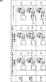
図9は、顔検出オフモード時の表示部50における表示を説明する図である。
FIG. 9 is a diagram illustrating a display on the
図9に示すように、顔検出オフモード時、液晶モニタ26にメニュー画面や設定画面が表示されていない状態で十字キー23の中央のボタン23Eを押下することにより合焦が指示される場合、合焦指示前には、表示中のライブビュー画像91に何も重畳されない。
As shown in FIG. 9, in the face detection off mode, when focusing is instructed by pressing the
合焦指示後、瞳検出部72により瞳領域が検出される。瞳領域が検出された場合、領域設定部73により合焦領域が瞳領域に設定され、表示中のライブビュー画像92には、合焦領域として瞳領域を表す瞳枠101が重畳される。そして、瞳枠101が表す瞳領域にピントが合わせられる。一方、瞳領域が検出されなかった場合、領域設定部73により合焦領域が顔領域に設定され、表示中のライブビュー画像92には、合焦領域として顔領域を表す顔枠102が重畳される。そして、顔枠102が表す顔領域にピントが合わせられる。合焦後、表示中のライブビュー画像93には、再び何も重畳されなくなる。
After the focusing instruction, the
また、顔検出オフモード時、レリーズボタン11を半押しすることにより合焦が指示される場合、合焦指示前には、表示中のライブビュー画像91に何も重畳されない。合焦指示後、領域設定部73により合焦領域が既定領域に設定され、表示中のライブビュー画像92には、合焦領域として既定領域を表す既定枠103が重畳される。そして、既定枠103が表す既定領域にピントが合わせられる。なお、図9の例では、既定領域は、奥行き方向の位置が最も撮影装置10に近い被写体の領域となっている。合焦後、表示中のライブビュー画像93には、既定枠103が重畳されたままとなる。
In the face detection off mode, when focusing is instructed by pressing the
(顔検出オンモード時の表示の説明)
図10は、顔検出オンモード時の表示部50における表示を説明する図である。(Explanation of display in face detection on mode)
FIG. 10 is a diagram illustrating a display on the
図10に示すように、顔検出オンモード時、液晶モニタ26にメニュー画面や設定画面が表示されていない状態で十字キー23の中央のボタン23Eを押下することにより合焦が指示される場合、合焦指示前には、表示中のライブビュー画像111に合焦領域の候補として顔領域を表す顔仮枠121が重畳される。
As shown in FIG. 10, in the face detection ON mode, when the focus is instructed by pressing the
合焦指示後、瞳検出部72により瞳領域が検出される。瞳領域が検出された場合、領域設定部73により合焦領域が瞳領域に設定され、表示中のライブビュー画像112には、合焦領域として瞳領域を表す瞳枠122が重畳される。そして、瞳枠122が表す瞳領域にピントが合わせられる。一方、瞳領域が検出されなかった場合、領域設定部73により合焦領域が顔領域に設定され、表示中のライブビュー画像112には、合焦領域として顔領域を表す顔枠123が重畳される。そして、顔枠123が表す顔領域にピントが合わせられる。合焦後、表示中のライブビュー画像113には、顔枠123が重畳される。
After the focusing instruction, the
また、顔検出オンモード時、レリーズボタン11を半押しすることにより合焦が指示される場合、合焦指示前には、表示中のライブビュー画像111には顔仮枠121が重畳される。合焦指示後、領域設定部73により合焦領域が顔領域に設定され、表示中のライブビュー画像112には、顔枠123が重畳される。合焦後、表示中のライブビュー画像113には、顔枠123が重畳されたままとなる。
Further, in the face detection on mode, when focusing is instructed by pressing the
なお、顔仮枠121が合焦領域ではなく合焦領域の候補を表していることを容易に認識できるように、顔仮枠121と、瞳枠122および顔枠123との間で、色、太さ、線種などを変更するようにしてもよい。
It should be noted that, in order to easily recognize that the
(撮影装置の処理の説明)
図11は、顔検出モードが顔検出オフモードである場合の撮影装置10の撮影処理である顔検出オフ撮影処理を説明するフローチャートである。この顔検出オフ撮影処理は、例えば、電源ボタン11Aが操作されることにより電源がオンにされたとき、開始される。(Explanation of processing of the photographing device)
FIG. 11 is a flowchart illustrating a face detection off shooting process which is a shooting process of the
図11のステップS11において、イメージセンサ42は、光学系41を介して集光された被写体からの光を画素単位で光電変換することにより画像の各画素の電気信号を取得する。イメージセンサ42は、画像の各画素の電気信号を画像処理部43に供給し、これにより、画像データが圧縮処理部44とマイクロコンピュータ47に供給される。
In step S11 of FIG. 11, the
ステップS12において、マイクロコンピュータ47は、画像処理部43から供給される画像データに基づく画像をライブビュー画像として表示部50に表示させる。
In step S12, the
ステップS13において、マイクロコンピュータ47の顔検出部71は、画像処理部43から供給される画像データから顔領域を検出する。顔検出部71は、顔領域を瞳検出部72、領域設定部73、および表示制御部74に供給する。
In step S13, the
ステップS14において、瞳検出部72は、操作部52からの操作信号に基づいて、液晶モニタ26にメニュー画面や設定画面が表示されていない状態で十字キー23の中央のボタン23Eが押下されたかどうかを判定する。ステップS14で中央のボタン23Eが押下されたと判定された場合、処理はステップS15に進む。
In step S14, whether or not the
ステップS15において、瞳検出部72は、顔検出部71から供給される顔領域に基づいて、画像処理部43から供給される画像データから瞳領域を検出する。
In step S15, the
ステップS16において、瞳検出部72は、ステップS15の処理により瞳領域が検出されたかどうかを判定する。ステップS16で瞳領域が検出されたと判定された場合、瞳検出部72は、検出された瞳領域を領域設定部73に供給する。そして、ステップS17において、領域設定部73は、瞳検出部72から供給される瞳領域を合焦領域として設定し、表示制御部74と図4の合焦制御部48に供給する。
In step S16, the
ステップS18において、表示制御部74は、領域設定部73から供給される瞳領域に基づいて、表示中のライブビュー画像に瞳枠を重畳して表示部50に表示させる。そして処理はステップS24に進む。
In step S18, the
一方、ステップS16で瞳領域が検出されていないと判定された場合、ステップS19において、領域設定部73は、顔検出部71から供給される顔領域を合焦領域として設定し、表示制御部74と合焦制御部48に供給する。
On the other hand, when it is determined in step S16 that the pupil region is not detected, the
ステップS20において、表示制御部74は、領域設定部73から供給される顔領域に基づいて、表示中のライブビュー画像に顔枠を重畳して表示部50に表示させる。そして処理はステップS24に進む。
In step S<b>20, the
また、ステップS14で中央のボタン23Eが押下されていないと判定された場合、処理はステップS21に進む。ステップS21において、領域設定部73は、操作部52から供給される操作信号に基づいて、レリーズボタン11が半押しされたかどうかを判定する。
If it is determined in step S14 that the
ステップS21でレリーズボタン11が半押しされたと判定された場合、ステップS22において、領域設定部73は、既定領域を合焦領域として設定し、表示制御部74と合焦制御部48に供給する。
When it is determined in step S21 that the
ステップS23において、表示制御部74は、領域設定部73から供給される既定領域に基づいて、表示中のライブビュー画像に既定枠を重畳して表示部50に表示させる。そして処理はステップS24に進む。
In step S23, the
ステップS24において、イメージセンサ42は、位相差情報を取得し、合焦制御部48は、領域設定部73からの合焦領域とイメージセンサ42からの位相差情報とに基づいて、合焦領域にピントが合うようにアクチュエータ49を制御し、光学系41を駆動する。
In step S24, the
ステップS25において、イメージセンサ42は、光学系41を介して集光された被写体からの光を画素単位で光電変換することにより画像の各画素の電気信号を取得する。イメージセンサ42は、画像の各画素の電気信号を画像処理部43に供給し、これにより、画像データが圧縮処理部44とマイクロコンピュータ47に供給される。
In step S25, the
ステップS26において、マイクロコンピュータ47は、画像処理部43から供給される画像データに基づく画像をライブビュー画像として表示部50に表示させる。また、表示制御部74は、合焦領域を表す枠をライブビュー画像に重畳して表示部50に表示させる。
In step S26, the
ステップS27において、マイクロコンピュータ47は、操作部52からの操作信号に基づいて、レリーズボタン11が全押しされたかどうかを判定する。ステップS27でレリーズボタン11が全押しされたと判定された場合、処理はステップS28に進む。
In step S27, the
ステップS28において、圧縮処理部44は、画像処理部43から供給される画像データを圧縮する。圧縮処理部44は、圧縮後の画像データをメディア制御部45に供給する。
In step S28, the
ステップS29において、メディア制御部45は、記録メディア46を制御し、圧縮処理部44から供給される圧縮後の画像データを記録メディア46に記録させ、処理をステップS30に進める。
In step S29, the
また、ステップS21でレリーズボタン11が半押しされていないと判定された場合、処理はステップS30に進む。
If it is determined in step S21 that the
ステップS30において、撮影装置10は、処理を終了するかどうか、例えば、電源ボタン11Aが操作されたかどうかを判定する。
In step S30, the
ステップS27でレリーズボタンが全押しされていないと判定された場合、または、ステップS30で処理を終了しないと判定された場合、合焦領域が既定領域以外であるときには、領域設定部73は、合焦領域を顔領域に設定する。これにより、光学系41は、顔領域にピントが合うように駆動される。
If it is determined in step S27 that the release button has not been fully pressed, or if it is determined in step S30 that the process is not to be ended, or if the focus area is other than the default area, the
一方、合焦領域が既定領域であるときには、領域設定部73は、合焦領域を既定領域のままにする。これにより、光学系41は、既定領域にピントが合うように駆動される。そして、処理はステップS11に戻り、以降の処理が繰り返される。このとき、合焦領域が既定領域である場合には、ステップS12の処理で、表示されるライブビュー画像に既定枠が重畳される。
On the other hand, when the focus area is the default area, the
一方、ステップS30で処理を終了すると判定された場合、処理は終了する。 On the other hand, if it is determined in step S30 that the process is to be ended, the process ends.
図12は、顔検出モードが顔検出オンモードである場合の撮影装置10の撮影処理である顔検出オン撮影処理を説明するフローチャートである。この顔検出オン撮影処理は、例えば、電源ボタン11Aが操作されることにより電源がオンにされたとき、開始される。
FIG. 12 is a flowchart illustrating a face detection on shooting process which is a shooting process of the
図12のステップS41乃至S43の処理は、図11のステップS11乃至S13の処理と同様であるので、説明は省略する。 The processing of steps S41 to S43 of FIG. 12 is the same as the processing of steps S11 to S13 of FIG.
ステップS44において、表示制御部74は、顔検出部71から供給される顔領域の顔仮枠を表示中のライブビュー画像に重畳して、表示部50に表示させる。
In step S44, the
ステップS45乃至S49の処理は、図11のステップS14乃至S18の処理と同様であるので、説明は省略する。 The processing of steps S45 to S49 is the same as the processing of steps S14 to S18 of FIG. 11, and thus description thereof will be omitted.
ステップS45で十字キー23の中央のボタン23Eが押下されていないと判定された場合、処理はステップS50に進む。ステップS50において、領域設定部73は、操作部52から供給される操作信号に基づいて、レリーズボタン11が半押しされたかどうかを判定する。
If it is determined in step S45 that the
ステップS50でレリーズボタン11が半押しされたと判定された場合、処理はステップS51に進む。また、ステップS47で瞳領域が検出されなかったと判定された場合、処理はステップS51に進む。
If it is determined in step S50 that the
ステップS51乃至S59の処理は、図11のステップS19,S20、およびS24乃至S30の処理と同様であるので、説明は省略する。但し、2回目以降のステップS44の処理では、仮顔枠ではなく、顔枠が表示される。 The processing of steps S51 to S59 is the same as the processing of steps S19, S20, and S24 to S30 of FIG. However, in the process of step S44 after the second time, the face frame is displayed instead of the temporary face frame.
なお、図示は省略するが、顔検出モードが登録顔検出モードである場合の撮影装置10の撮影処理は、ステップS43の処理で、取得された画像データと登録顔画像の画像データとのマッチングが行われる点を除いて、顔検出オン撮影処理と同様である。マッチングにより登録顔画像の領域が検出された場合、登録顔画像の領域が顔領域とされ、登録顔画像の領域が検出されない場合、登録顔画像以外の顔画像の領域が顔領域とされる。
Although illustration is omitted, in the image capturing process of the
また、顔検出モードがスマイルシャッタモードである場合の撮影装置10の撮影処理は、ステップS45乃至S49の処理が行われない点を除いて、顔検出オン撮影処理と同様である。
The shooting process of the
以上のように、中央のボタン23Eは、撮影単位で合焦対象とする被写体の種類として瞳を選択する選択部として機能するため、撮影装置10は、撮影後、中央のボタン23Eが押下されるまで、合焦領域を顔領域または既定領域に設定する。
As described above, since the
また、撮影装置10は、中央のボタン23Eにより撮影単位で合焦対象とする被写体の種類として瞳が選択された場合、瞳領域を合焦領域として設定する。従って、合焦対象とする被写体の種類としての瞳を撮影ごとに容易に設定することができる。また、合焦対象とする被写体の種類としての瞳を撮影ごとに素早く設定することができる。
In addition, when the pupil is selected as the type of subject to be focused on a photographing unit by the
<第2実施の形態>
(撮影装置の第2実施の形態の構成例)
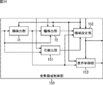
図13は、本開示を適用した撮影装置10の第2実施の形態のマイクロコンピュータ47により実現される合焦領域制御部の構成例を示すブロック図である。<Second Embodiment>
(Example of Configuration of Second Embodiment of Imaging Device)
FIG. 13 is a block diagram showing a configuration example of a focusing area control unit realized by the
撮影装置10の第2実施の形態は、合焦領域制御部を除いて第1実施の形態と基本的に同様に構成される。但し、レリーズボタン11の半押しは、合焦を指示する指示部として機能する。即ち、撮影装置10の第2実施の形態では、十字キー23の中央のボタン23Eが押下されただけでは合焦されず、中央のボタン23Eが押下された後、レリーズボタン11が半押しされると合焦される。
The second embodiment of the photographing
図13に示す構成のうち、図5の構成と同じ構成には同じ符号を付してある。重複する説明については適宜省略する。 Of the configurations shown in FIG. 13, the same configurations as the configurations of FIG. 5 are denoted by the same reference numerals. A duplicate description will be omitted as appropriate.
図13の合焦領域制御部130の構成は、領域設定部73の代わりに領域設定部131が設けられる点が図5の構成と異なる。
The configuration of the focusing
合焦領域制御部130の領域設定部131は、メモリ51から顔検出モードを読み出す。領域設定部131は、操作部52からレリーズボタン11の半押しを表す操作信号が供給された場合、顔検出モードに基づいて、撮影単位で、顔領域、瞳領域、または既定領域を合焦領域として設定する。領域設定部131は、合焦領域を表示制御部74と図4の合焦制御部48に供給する。
The
(撮影装置の処理の説明)
撮影装置10の第2実施の形態による顔検出モードに応じた撮影処理は、中央のボタン23Eが押下された場合、レリーズボタン11が半押しされたかどうかの判定が、光学系の駆動の前に行われる点を除いて、第1実施の形態と同様である。レリーズボタン11が半押しされたと判定された場合、合焦領域にピントが合うように光学系が駆動されるが、レリーズボタン11が半押しされていないと判定された場合、光学系は駆動されない。(Explanation of processing of the photographing device)
In the shooting processing according to the face detection mode according to the second embodiment of the
以上のように、撮影装置10の第2実施の形態では、合焦領域によらず、レリーズボタン11の半押しで合焦させることができる。従って、レリーズボタン11の半押しで合焦を指示することに慣れたユーザの操作を容易にすることができる。
As described above, in the second embodiment of the photographing
これに対して、撮影装置10の第1実施の形態では、中央のボタン23Eの押下という1つの操作で、合焦対象とする被写体の種類の選択および合焦指示を行うことができる。従って、ユーザの操作を簡易化することができる。
On the other hand, in the first embodiment of the
<第3実施の形態>
(撮影装置の第3実施の形態の構成例)
図14は、本開示を適用した撮影装置10の第3実施の形態のマイクロコンピュータ47により実現される合焦領域制御部の構成例を示すブロック図である。<Third Embodiment>
(Example of Configuration of Third Embodiment of Imaging Device)
FIG. 14 is a block diagram showing a configuration example of a focusing area control unit realized by the
撮影装置10の第3実施の形態は、合焦領域制御部を除いて第1実施の形態と基本的に同様に構成される。
The third embodiment of the
但し、十字キー23の上のボタン23Aは、液晶モニタ26にメニュー画面や設定画面が表示されていない状態で撮影単位の合焦対象とする被写体の種類として花を選択するときにも、押下される。即ち、撮影装置10の第3実施の形態では、液晶モニタ26にメニュー画面や設定画面が表示されていない状態で、上のボタン23Aが、撮影単位で合焦対象とする被写体の種類として花を選択する選択部として機能する。
However, the
図14に示す構成のうち、図5の構成と同じ構成には同じ符号を付してある。重複する説明については適宜省略する。 Of the configurations shown in FIG. 14, the same configurations as the configurations of FIG. 5 are denoted by the same reference numerals. A duplicate description will be omitted as appropriate.
図14の合焦領域制御部150の構成は、新たに花検出部151が設けられる点、および、領域設定部73、表示制御部74の代わりに領域設定部152、表示制御部153が設けられる点が、図5の構成と異なる。
In the configuration of the focus
合焦領域制御部150の花検出部151は、液晶モニタ26にメニュー画面や設定画面が表示されていない状態で操作部52から十字キー23の上のボタン23Aの押下を表す操作信号が供給されたかどうかを判定する。花検出部151は、判定結果に基づいて、画像処理部43から供給される画像データから花領域を検出する。花検出部151は、花領域を領域設定部152に供給する。
The
領域設定部152は、メモリ51から顔検出モードを読み出す。領域設定部152は、顔検出モードと、操作部52から供給されるレリーズボタン11の半押しを表す操作信号とに基づいて、撮影単位で、顔領域、瞳領域、花領域、または既定領域を合焦領域として設定する。領域設定部152は、合焦領域を表示制御部153と図4の合焦制御部48に供給する。
The
表示制御部153は、メモリ51から顔検出モードを読み出す。表示制御部153は、顔検出モードに基づいて、顔検出部71から供給される顔領域を表す顔枠を表示中のライブビュー画像に重畳して、表示部50に表示させる。また、表示制御部153は、領域設定部152から供給される合焦領域を表す枠を表示中のライブビュー画像に重畳して、表示部50に表示させる。
The
(撮影装置の処理の説明)
図15は、撮影装置10の第3実施の形態による顔検出オフ撮影処理を説明するフローチャートである。この顔検出オフ撮影処理は、例えば、電源ボタン11Aが操作されることにより電源がオンにされたとき、開始される。(Explanation of processing of the photographing device)
FIG. 15 is a flowchart illustrating a face detection off shooting process according to the third embodiment of the
図15のステップS71乃至S80の処理は、図11のステップS11乃至S20の処理と同様であるので、説明は省略する。 The processing of steps S71 to S80 in FIG. 15 is the same as the processing of steps S11 to S20 in FIG.
ステップS74で中央のボタン23Eが押下されていないと判定された場合、処理はステップS81に進む。ステップS81において、花検出部151は、操作部52からの操作信号に基づいて、液晶モニタ26にメニュー画面や設定画面が表示されていない状態で十字キー23の上のボタン23Aが押下されたかどうかを判定する。
If it is determined in step S74 that the
ステップS81で上のボタン23Aが押下されたと判定された場合、処理はステップS82に進む。ステップS82において、花検出部151は、画像処理部43から供給される画像データから花領域を検出し、領域設定部152に供給する。
If it is determined in step S81 that the
ステップS83において、領域設定部152は、花検出部151から供給される花領域を合焦領域として設定し、表示制御部153と図4の合焦制御部48に供給する。
In step S83, the
ステップS84において、表示制御部153は、領域設定部152から供給される花領域に基づいて、表示中のライブビュー画像に花領域を表す花枠を重畳して表示部50に表示させる。そして処理はステップS88に進む。
In step S84, the
ステップS85乃至S94の処理は、図11のステップS21乃至S30の処理と同様であるので、説明は省略する。 The processing of steps S85 to S94 is the same as the processing of steps S21 to S30 of FIG. 11, and thus description thereof will be omitted.
図16は、撮影装置10の第3の実施の形態による顔検出オン撮影処理を説明するフローチャートである。この顔検出オン撮影処理は、例えば、電源ボタン11Aが操作されることにより電源がオンにされたとき、開始される。
FIG. 16 is a flowchart illustrating the face detection on shooting processing according to the third embodiment of the
図16のステップS111乃至S121の処理は、図12のステップS41乃至S49,S51,およびS52の処理と同様であるので、説明は省略する。 The processing of steps S111 to S121 of FIG. 16 is the same as the processing of steps S41 to S49, S51, and S52 of FIG. 12, and thus description thereof will be omitted.
ステップS122乃至S126の処理は、図15のステップS81乃至S85の処理と同様であるので、説明は省略する。 The processing of steps S122 to S126 is the same as the processing of steps S81 to S85 of FIG. 15, and thus description thereof will be omitted.
ステップS126でレリーズボタン11が半押しされたと判定された場合、処理はステップS120に進む。一方、ステップS126でレリーズボタン11が半押しされていないと判定された場合、処理はステップS133に進む。
If it is determined in step S126 that the
ステップS127乃至S133の処理は、図11のステップS24乃至S30の処理と同様であるので、説明は省略する。 The processing of steps S127 to S133 is the same as the processing of steps S24 to S30 of FIG. 11, and thus description thereof will be omitted.
以上のように、上のボタン23Aは、撮影単位で合焦対象とする被写体の種類として花を選択する選択部として機能するため、撮影装置10は、撮影後、上のボタン23Aが押下されるまで、合焦領域を顔領域または既定領域に設定する。
As described above, since the
また、撮影装置10の第3実施の形態は、中央のボタン23Eにより撮影単位で合焦対象とする被写体の種類として瞳が選択された場合、瞳領域を合焦領域として設定する。さらに、撮影装置10の第3実施の形態は、上のボタン23Aにより撮影単位で合焦対象とする被写体の種類として花が選択された場合、花領域を合焦領域として設定する。従って、合焦対象とする被写体の種類としての瞳または花を撮影ごとに容易に設定することができる。また、合焦対象とする被写体の種類としての瞳または花を撮影ごとに素早く設定することができる。
In addition, in the third embodiment of the
なお、撮影装置10の第3実施の形態においても、第2実施の形態と同様に、上のボタン23Aおよび中央のボタン23Eを押下するだけでは合焦されず、さらにレリーズボタン11を半押ししたときに合焦されるようにしてもよい。
Also in the third embodiment of the
<第4実施の形態>
(本開示を適用したコンピュータの説明)
上述した一連の処理は、ハードウエアにより実行することもできるし、ソフトウエアにより実行することもできる。一連の処理をソフトウエアにより実行する場合には、そのソフトウエアを構成するプログラムが、コンピュータにインストールされる。ここで、コンピュータには、専用のハードウエアに組み込まれているコンピュータや、各種のプログラムをインストールすることで、各種の機能を実行することが可能な、例えば汎用のパーソナルコンピュータなどが含まれる。<Fourth Embodiment>
(Description of computer to which the present disclosure is applied)
The series of processes described above can be executed by hardware or software. When the series of processes is executed by software, a program forming the software is installed in the computer. Here, the computer includes a computer incorporated in dedicated hardware and, for example, a general-purpose personal computer capable of executing various functions by installing various programs.
図17は、上述した一連の処理をプログラムにより実行するコンピュータのハードウエアの構成例を示すブロック図である。 FIG. 17 is a block diagram showing a configuration example of hardware of a computer that executes the series of processes described above by a program.
コンピュータ200において、CPU(Central Processing Unit)201,ROM(Read Only Memory)202,RAM(Random Access Memory)203は、バス204により相互に接続されている。
In the
バス204には、さらに、入出力インタフェース205が接続されている。入出力インタフェース205には、撮影部206、入力部207、出力部208、記憶部209、通信部210、及びドライブ211が接続されている。
An input/
撮影部206は、光学系41、イメージセンサ42、アクチュエータ49、画像処理部43等により構成される。撮影部206は、被写体からの光により画像データを取得する。
The
入力部207は、操作部52に対応し、キーボード、マウス、マイクロフォンなどよりなる。出力部208は、ディスプレイ、スピーカなどよりなる。記憶部209は、ハードディスクや不揮発性のメモリなどよりなる。通信部210は、ネットワークインタフェースなどよりなる。ドライブ211は、磁気ディスク、光ディスク、光磁気ディスク、又は半導体メモリなどのリムーバブルメディア212を駆動する。
The
以上のように構成されるコンピュータ200では、CPU201が、例えば、記憶部209に記憶されているプログラムを、入出力インタフェース205及びバス204を介して、RAM203にロードして実行することにより、上述した一連の処理が行われる。
In the
コンピュータ200(CPU201)が実行するプログラムは、例えば、パッケージメディア等としてのリムーバブルメディア212に記録して提供することができる。また、プログラムは、ローカルエリアネットワーク、インターネット、デジタル衛星放送といった、有線または無線の伝送媒体を介して提供することができる。
The program executed by the computer 200 (CPU 201) can be provided by being recorded in a
コンピュータ200では、プログラムは、リムーバブルメディア212をドライブ211に装着することにより、入出力インタフェース205を介して、記憶部209にインストールすることができる。また、プログラムは、有線または無線の伝送媒体を介して、通信部210で受信し、記憶部209にインストールすることができる。その他、プログラムは、ROM202や記憶部209に、あらかじめインストールしておくことができる。
In the
なお、コンピュータ200が実行するプログラムは、本明細書で説明する順序に沿って時系列に処理が行われるプログラムであっても良いし、並列に、あるいは呼び出しが行われたとき等の必要なタイミングで処理が行われるプログラムであっても良い。
It should be noted that the program executed by the
本明細書に記載された効果はあくまで例示であって限定されるものではなく、他の効果があってもよい。 The effects described in the present specification are merely examples and are not limited, and may have other effects.
また、本開示の実施の形態は、上述した実施の形態に限定されるものではなく、本開示の要旨を逸脱しない範囲において種々の変更が可能である。 The embodiments of the present disclosure are not limited to the above-described embodiments, and various modifications can be made without departing from the gist of the present disclosure.
例えば、合焦対象とする被写体の種類は、瞳、花以外の種類(例えば、風景、建物、動物、ペット、料理など)であってもよい。また、合焦対象とする被写体の種類の数は、3以上にすることができる。 For example, the type of subject to be focused may be a type other than eyes and flowers (for example, landscape, building, animal, pet, food, etc.). Further, the number of types of subjects to be focused can be three or more.
さらに、撮影単位で合焦対象とする被写体の種類を選択する選択部として機能するボタンは、十字キー23以外のボタン(例えば、カスタムボタン13,カスタムボタン18,AELボタン21など)であってもよい。但し、被写体の種類ごとに選択部として機能するボタンは異なる。また、選択部は、液晶モニタ26上に表示され、十字キー23により操作されるようにしてもよい。液晶モニタ26が、タッチパネルにより構成される場合には、液晶モニタ26上の選択部は、タッチされることにより操作される。
Further, even if the button functioning as a selection unit that selects the type of subject to be focused on a shooting unit basis is a button other than the cross key 23 (for example,
また、撮影単位で選択される被写体の種類は、合焦対象とする被写体の種類ではなく、最適な露出、ホワイトバランスなどを選択するための測光や測色の対象とする被写体の種類であってもよい。 Also, the type of subject selected in each shooting unit is not the type of subject to be focused, but the type of subject to be metered or measured to select the optimum exposure, white balance, etc. Good.
さらに、顔領域を検出せずに瞳領域を検出可能な場合、顔検出オフモード時には顔領域は検出されないようにすることができる。また、撮影装置10は、位相差情報ではなく、コントラスト情報を取得し、コントラスト情報に基づいて合焦を行うようにしてもよい。
Furthermore, when the pupil area can be detected without detecting the face area, the face area can be prevented from being detected in the face detection off mode. Further, the
10 撮影装置, 11 レリーズボタン, 23A乃至23E ボタン, 42 イメージセンサ, 48 合焦制御部, 72 瞳検出部, 73 領域設定部, 151 花検出部, 152 領域設定部 10 photographing device, 11 release button, 23A to 23E buttons, 42 image sensor, 48 focusing control section, 72 pupil detecting section, 73 area setting section, 151 flower detecting section, 152 area setting section
Claims (5)
前記取得部により取得された前記画像から、合焦対象とする被写体の第1の種類の領域を検出する第1の検出部と、
前記画像の撮影単位で、前記被写体の前記第1の種類を選択する第1の選択部とは異なり、前記第1の種類を構成する第2の種類を選択する第2の選択部と、
前記第2の選択部により前記第2の種類が選択された場合、前記第1の検出部により検出された前記第1の種類の領域に基づいて、前記第2の種類の領域を検出する第2の検出部と、
前記第2の検出部により前記第2の種類の領域が検出された場合、前記2の検出部により検出された前記第2の種類の領域を前記画像の合焦領域として設定する領域設定部と
を備え、
前記領域設定部は、前記第2の検出部により前記第2の種類の領域が検出されなかった場合、前記第1の検出部により検出された前記第1の種類の領域を前記画像の合焦領域として設定する
撮影装置。 An acquisition unit that acquires images,
A first detection unit that detects, from the image acquired by the acquisition unit, an area of a first type of a subject to be focused,
A second selection unit that selects a second type that constitutes the first type, unlike a first selection unit that selects the first type of the subject, for each unit of image capturing;
When the second type is selected by the second selection unit, the second type region is detected based on the first type region detected by the first detection unit. 2 detection units,
An area setting unit that, when the second type of area is detected by the second detecting unit, sets the second type of area detected by the second detecting unit as a focus area of the image; Equipped with
When the second detection unit does not detect the second type region, the region setting unit focuses the image on the first type region detected by the first detection unit. An imaging device that is set as an area .
前記指示部により前記合焦が指示された場合、前記領域設定部により設定された前記合焦領域で前記合焦を行うように、前記取得部を制御する合焦制御部をさらに備える
請求項1に記載の撮影装置。 An instruction section for instructing focus,
The focusing control unit configured to control the acquisition unit to perform the focusing in the focusing region set by the region setting unit when the focusing unit instructs the focusing. The imaging device described in.
前記第3の選択部により前記第3の種類が選択された場合、前記第3の種類の領域を前記画像から検出する第3の検出部と
をさらに備え、
前記領域設定部は、前記第3の検出部により検出された前記第3の種類の領域を前記合焦領域として設定する
請求項1または2に記載の撮影装置。 A third selection unit that selects a third type of the subject in units of the images captured by the acquisition unit;
When the third type is selected by the third selection unit, a third detection unit that detects the region of the third type from the image is further included.
The area setting section imaging apparatus according to claim 1 or 2 to set the third the third type of area detected by the detection unit as the focus area.
画像を取得する取得ステップと、
取得された前記画像から、合焦対象とする被写体の第1の種類の領域を検出する第1の検出ステップと、
前記画像の撮影単位で、前記被写体の前記第1の種類を選択する第1の選択部とは異なり、前記第1の種類を構成する第2の種類を第2の選択部で選択する選択ステップと、
前記第2の種類が選択された場合、検出された前記第1の種類の領域に基づいて、前記第2の種類の領域を検出する第2の検出ステップと、
前記第2の種類の領域が検出された場合、検出された前記第2の種類の領域を前記画像の合焦領域として設定する領域設定ステップと
を含み、
前記領域設定ステップでは、前記第2の種類の領域が検出されなかった場合、検出された前記第1の種類の領域を前記画像の合焦領域として設定する
撮影方法。 The shooting device
An acquisition step to acquire the image,
A first detection step of detecting, from the acquired image, a first type region of a subject to be focused,
A selection step of selecting, in a second selection unit, a second type that constitutes the first type, unlike a first selection unit that selects the first type of the subject for each image capturing unit. When,
A second detection step of detecting the second type region based on the detected first type region when the second type is selected;
An area setting step of setting the detected second type area as a focus area of the image when the second type area is detected,
In the area setting step, when the second type area is not detected, the detected first type area is set as a focused area of the image .
前記画像から、前記被写体の前記第1の種類の領域を検出する第1の検出部と、
前記第2の選択部により前記第2の種類が選択された場合、前記第1の検出部により検出された前記第1の種類の領域に基づいて、前記第2の種類の領域を検出する第2の検出部と、
前記第2の検出部により前記第2の種類の領域が検出された場合、前記2の検出部により検出された前記第2の種類の領域を前記画像の合焦領域として設定する領域設定部と
して機能させ、
前記領域設定部は、前記第2の検出部により前記第2の種類の領域が検出されなかった場合、前記第1の検出部により検出された前記第1の種類の領域を前記画像の合焦領域として設定する
ためのプログラム。 Unlike the acquisition unit that acquires an image, the first selection unit that selects the first type of the subject to be focused in the unit of shooting of the image, and the first selection unit, the first selection unit is different from the first selection unit. A computer for controlling the photographing control device, the computer including a second selection unit that selects a second type that configures a type;
A first detection unit that detects the first type region of the subject from the image;
When the second type is selected by the second selection unit, the second type region is detected based on the first type region detected by the first detection unit. 2 detection units,
An area setting unit that, when the second type of area is detected by the second detecting unit, sets the second type of area detected by the second detecting unit as a focus area of the image; And let it work ,
When the second detection unit does not detect the second type region, the region setting unit focuses the image on the first type region detected by the first detection unit. Program for setting as a region .
Applications Claiming Priority (3)
| Application Number | Priority Date | Filing Date | Title |
|---|---|---|---|
| JP2013197389 | 2013-09-24 | ||
| JP2013197389 | 2013-09-24 | ||
| PCT/JP2014/074241 WO2015045911A1 (en) | 2013-09-24 | 2014-09-12 | Imaging device, imaging method and program |
Related Child Applications (1)
| Application Number | Title | Priority Date | Filing Date |
|---|---|---|---|
| JP2020011381A Division JP7004014B2 (en) | 2013-09-24 | 2020-01-28 | Shooting equipment, shooting method, and program |
Publications (2)
| Publication Number | Publication Date |
|---|---|
| JPWO2015045911A1 JPWO2015045911A1 (en) | 2017-03-09 |
| JP6701512B2 true JP6701512B2 (en) | 2020-05-27 |
Family
ID=52743053
Family Applications (4)
| Application Number | Title | Priority Date | Filing Date |
|---|---|---|---|
| JP2015539109A Active JP6701512B2 (en) | 2013-09-24 | 2014-09-12 | Imaging device, imaging method, and program |
| JP2020011381A Active JP7004014B2 (en) | 2013-09-24 | 2020-01-28 | Shooting equipment, shooting method, and program |
| JP2021139835A Active JP7276393B2 (en) | 2013-09-24 | 2021-08-30 | Imaging device and imaging method |
| JP2023076545A Pending JP2023095973A (en) | 2013-09-24 | 2023-05-08 | Photographing device, photographing method, and program |
Family Applications After (3)
| Application Number | Title | Priority Date | Filing Date |
|---|---|---|---|
| JP2020011381A Active JP7004014B2 (en) | 2013-09-24 | 2020-01-28 | Shooting equipment, shooting method, and program |
| JP2021139835A Active JP7276393B2 (en) | 2013-09-24 | 2021-08-30 | Imaging device and imaging method |
| JP2023076545A Pending JP2023095973A (en) | 2013-09-24 | 2023-05-08 | Photographing device, photographing method, and program |
Country Status (5)
| Country | Link |
|---|---|
| US (4) | US10440252B2 (en) |
| EP (1) | EP3032307A4 (en) |
| JP (4) | JP6701512B2 (en) |
| CN (1) | CN105765434B (en) |
| WO (1) | WO2015045911A1 (en) |
Families Citing this family (10)
| Publication number | Priority date | Publication date | Assignee | Title |
|---|---|---|---|---|
| EP3032307A4 (en) * | 2013-09-24 | 2017-02-22 | Sony Corporation | Imaging device, imaging method and program |
| JP2018046514A (en) * | 2016-09-16 | 2018-03-22 | オリンパス株式会社 | Imaging device |
| US10958825B2 (en) * | 2017-10-17 | 2021-03-23 | Canon Kabushiki Kaisha | Electronic apparatus and method for controlling the same |
| EP3904956A4 (en) * | 2018-12-28 | 2022-02-16 | Sony Group Corporation | Imaging device, imaging method, and program |
| US11985420B2 (en) * | 2019-03-27 | 2024-05-14 | Sony Group Corporation | Image processing device, image processing method, program, and imaging device |
| JP7279169B2 (en) * | 2019-08-14 | 2023-05-22 | 富士フイルム株式会社 | IMAGING DEVICE, METHOD OF OPERATION OF IMAGING DEVICE, AND PROGRAM |
| JP7418104B2 (en) | 2019-08-30 | 2024-01-19 | キヤノン株式会社 | Image processing device and method of controlling the image processing device |
| JP2021173803A (en) * | 2020-04-21 | 2021-11-01 | キヤノン株式会社 | Imaging apparatus and method for controlling the same, program, and storage medium |
| CN111866392B (en) * | 2020-07-31 | 2021-10-08 | Oppo广东移动通信有限公司 | Shooting prompting method and device, storage medium and electronic equipment |
| WO2022209342A1 (en) * | 2021-03-30 | 2022-10-06 | ソニーグループ株式会社 | Imaging device, focus control method, and program |
Family Cites Families (65)
| Publication number | Priority date | Publication date | Assignee | Title |
|---|---|---|---|---|
| JP2662650B2 (en) | 1987-11-06 | 1997-10-15 | ミノルタ株式会社 | Automatic focusing device |
| DE68929375T2 (en) | 1988-09-22 | 2002-11-21 | Asahi Optical Co Ltd | Control device for image enlargement of a camera |
| JPH08265631A (en) * | 1995-03-27 | 1996-10-11 | Canon Inc | Automatic focus adjustment device |
| JP2003107335A (en) | 2001-09-28 | 2003-04-09 | Ricoh Co Ltd | Image pickup device, automatic focusing method, and program for making computer execute the method |
| US7298412B2 (en) * | 2001-09-18 | 2007-11-20 | Ricoh Company, Limited | Image pickup device, automatic focusing method, automatic exposure method, electronic flash control method and computer program |
| JP2004053722A (en) * | 2002-07-17 | 2004-02-19 | Fuji Photo Film Co Ltd | Camera |
| EP2955662B1 (en) * | 2003-07-18 | 2018-04-04 | Canon Kabushiki Kaisha | Image processing device, imaging device, image processing method |
| US20050024516A1 (en) * | 2003-07-31 | 2005-02-03 | Robert Fish | Digital camera |
| US8194173B2 (en) * | 2004-07-16 | 2012-06-05 | Nikon Corporation | Auto-focusing electronic camera that focuses on a characterized portion of an object |
| US7791642B2 (en) * | 2004-12-13 | 2010-09-07 | Fujifilm Corporation | Image-taking apparatus |
| JP4577113B2 (en) * | 2005-06-22 | 2010-11-10 | オムロン株式会社 | Object determining device, imaging device, and monitoring device |
| JP4626425B2 (en) * | 2005-07-11 | 2011-02-09 | 富士フイルム株式会社 | Imaging apparatus, imaging method, and imaging program |
| JP2007041119A (en) * | 2005-08-01 | 2007-02-15 | Olympus Imaging Corp | Imaging apparatus and imaging method |
| JP4608425B2 (en) | 2005-12-21 | 2011-01-12 | オリンパス株式会社 | Imaging system |
| JP5098259B2 (en) * | 2006-09-04 | 2012-12-12 | 株式会社ニコン | camera |
| JP4218720B2 (en) * | 2006-09-22 | 2009-02-04 | ソニー株式会社 | IMAGING DEVICE, IMAGING DEVICE CONTROL METHOD, AND COMPUTER PROGRAM |
| US7860382B2 (en) * | 2006-10-02 | 2010-12-28 | Sony Ericsson Mobile Communications Ab | Selecting autofocus area in an image |
| WO2008051907A1 (en) * | 2006-10-20 | 2008-05-02 | Cardiomems, Inc. | Method and apparatus for measuring pressure inside a fluid system |
| US8102465B2 (en) * | 2006-11-07 | 2012-01-24 | Fujifilm Corporation | Photographing apparatus and photographing method for photographing an image by controlling light irradiation on a subject |
| JP4697606B2 (en) * | 2007-01-24 | 2011-06-08 | 富士フイルム株式会社 | Imaging apparatus and focus control method |
| JP4902562B2 (en) * | 2007-02-07 | 2012-03-21 | パナソニック株式会社 | Imaging apparatus, image processing apparatus, control method, and program |
| JP5056061B2 (en) * | 2007-02-22 | 2012-10-24 | 株式会社ニコン | Imaging device |
| BRMU8701096Y1 (en) * | 2007-06-26 | 2014-09-30 | Dental Morelli Ltda | CONSTRUCTIVE PROVISION INTRODUCED IN SUPPORT FOR ORTHODONTIC ELASTICS |
| US8396330B2 (en) * | 2007-07-24 | 2013-03-12 | Sharp Laboratories Of America, Inc. | Image upscaling based upon directional interpolation |
| JP2009049639A (en) * | 2007-08-17 | 2009-03-05 | Fujifilm Corp | Image pick-up device |
| JP5099488B2 (en) * | 2007-08-31 | 2012-12-19 | カシオ計算機株式会社 | Imaging apparatus, face recognition method and program thereof |
| JP4466702B2 (en) * | 2007-09-12 | 2010-05-26 | カシオ計算機株式会社 | Imaging apparatus and imaging control program |
| JP4518131B2 (en) * | 2007-10-05 | 2010-08-04 | 富士フイルム株式会社 | Imaging method and apparatus |
| JP2009118009A (en) | 2007-11-02 | 2009-05-28 | Sony Corp | Imaging apparatus, method for controlling same, and program |
| WO2010061352A2 (en) * | 2008-11-26 | 2010-06-03 | Hiok Nam Tay | Auto-focus image system |
| JP2010186098A (en) | 2009-02-13 | 2010-08-26 | Panasonic Corp | Imaging apparatus |
| JP4748244B2 (en) * | 2009-03-31 | 2011-08-17 | カシオ計算機株式会社 | Image selection apparatus, image selection method, and program |
| KR101594295B1 (en) * | 2009-07-07 | 2016-02-16 | 삼성전자주식회사 | Photographing apparatus and photographing method |
| JP2011027847A (en) * | 2009-07-22 | 2011-02-10 | Fujifilm Corp | Af frame automatic tracking system |
| JP4868075B2 (en) * | 2009-10-09 | 2012-02-01 | 株式会社ニコン | Imaging device |
| KR101594298B1 (en) * | 2009-11-17 | 2016-02-16 | 삼성전자주식회사 | Apparatus and method for adjusting focus in digital image processing device |
| US20110242395A1 (en) * | 2010-04-01 | 2011-10-06 | Sanyo Electric Co., Ltd. | Electronic device and image sensing device |
| JP2011234002A (en) * | 2010-04-26 | 2011-11-17 | Kyocera Corp | Imaging device and terminal device |
| JP2012015889A (en) * | 2010-07-02 | 2012-01-19 | Sony Corp | Image processing device and image processing method |
| JP5556527B2 (en) * | 2010-07-16 | 2014-07-23 | 株式会社リコー | Image forming apparatus |
| US9148557B2 (en) * | 2010-07-16 | 2015-09-29 | Canon Kabushiki Kaisha | Focus adjustment apparatus and method, and image capturing apparatus and control method thereof |
| JP5629533B2 (en) * | 2010-08-30 | 2014-11-19 | キヤノン株式会社 | Imaging apparatus, control method therefor, program, and storage medium |
| JP2012054810A (en) * | 2010-09-02 | 2012-03-15 | Olympus Corp | Image processing device, image processing method, imaging apparatus, and image processing program |
| KR101817650B1 (en) * | 2010-09-08 | 2018-01-11 | 삼성전자주식회사 | Focusing Appratus |
| KR101755598B1 (en) * | 2010-10-27 | 2017-07-07 | 삼성전자주식회사 | Digital photographing apparatus and control method thereof |
| JP5669549B2 (en) | 2010-12-10 | 2015-02-12 | オリンパスイメージング株式会社 | Imaging device |
| JP5156108B2 (en) * | 2011-04-23 | 2013-03-06 | オリンパスイメージング株式会社 | Imaging apparatus and imaging method |
| JP2013026664A (en) * | 2011-07-15 | 2013-02-04 | Olympus Imaging Corp | External apparatus, camera system, image pickup method, and program |
| JP2013070164A (en) * | 2011-09-21 | 2013-04-18 | Olympus Imaging Corp | Imaging device and imaging method |
| WO2013047105A1 (en) * | 2011-09-29 | 2013-04-04 | 富士フイルム株式会社 | Image processing device, image processing method, program, recording medium, and imaging device |
| JP6049333B2 (en) * | 2011-10-14 | 2016-12-21 | キヤノン株式会社 | FOCUS DETECTION DEVICE AND FOCUS DETECTION DEVICE CONTROL METHOD |
| JP2013160295A (en) * | 2012-02-03 | 2013-08-19 | Toyota Motor Corp | Dry belt type continuously variable transmission |
| JP5896767B2 (en) * | 2012-02-06 | 2016-03-30 | キヤノン株式会社 | Imaging apparatus and focus control method |
| US9372874B2 (en) * | 2012-03-15 | 2016-06-21 | Panasonic Intellectual Property Corporation Of America | Content processing apparatus, content processing method, and program |
| JP2014056169A (en) | 2012-09-13 | 2014-03-27 | Olympus Imaging Corp | Focus adjustment device and focus adjustment method |
| EP3032307A4 (en) * | 2013-09-24 | 2017-02-22 | Sony Corporation | Imaging device, imaging method and program |
| KR20160050755A (en) * | 2014-10-31 | 2016-05-11 | 삼성전자주식회사 | Electronic Device and Method for Recognizing Iris by the same |
| JP6512810B2 (en) * | 2014-12-11 | 2019-05-15 | キヤノン株式会社 | Image pickup apparatus, control method and program |
| RU2679011C1 (en) * | 2015-09-16 | 2019-02-05 | Кэнон Кабусики Кайся | Image sensor and image capture device |
| KR20170046413A (en) * | 2015-10-21 | 2017-05-02 | 삼성전자주식회사 | Method for detecting eye of subject and electronic device thereof |
| KR102392789B1 (en) * | 2015-10-21 | 2022-05-02 | 삼성전자주식회사 | A method for setting focus and electronic device thereof |
| US10225460B2 (en) * | 2016-08-31 | 2019-03-05 | Canon Kabushiki Kaisha | Electronic device and method of controlling the same |
| JP2018207309A (en) * | 2017-06-05 | 2018-12-27 | オリンパス株式会社 | Imaging apparatus, imaging method and program |
| JP6602361B2 (en) * | 2017-10-16 | 2019-11-06 | キヤノン株式会社 | Electronic device and control method thereof |
| US10958825B2 (en) * | 2017-10-17 | 2021-03-23 | Canon Kabushiki Kaisha | Electronic apparatus and method for controlling the same |
-
2014
- 2014-09-12 EP EP14848520.4A patent/EP3032307A4/en active Pending
- 2014-09-12 WO PCT/JP2014/074241 patent/WO2015045911A1/en active Application Filing
- 2014-09-12 JP JP2015539109A patent/JP6701512B2/en active Active
- 2014-09-12 CN CN201480051175.3A patent/CN105765434B/en active Active
- 2014-09-12 US US15/022,145 patent/US10440252B2/en active Active
-
2019
- 2019-09-18 US US16/574,162 patent/US10972652B2/en active Active
-
2020
- 2020-01-28 JP JP2020011381A patent/JP7004014B2/en active Active
-
2021
- 2021-04-01 US US17/220,572 patent/US11659277B2/en active Active
- 2021-08-30 JP JP2021139835A patent/JP7276393B2/en active Active
-
2023
- 2023-05-02 US US18/310,721 patent/US20230269471A1/en active Pending
- 2023-05-08 JP JP2023076545A patent/JP2023095973A/en active Pending
Also Published As
| Publication number | Publication date |
|---|---|
| JP2021185432A (en) | 2021-12-09 |
| US10440252B2 (en) | 2019-10-08 |
| US11659277B2 (en) | 2023-05-23 |
| US10972652B2 (en) | 2021-04-06 |
| JP2023095973A (en) | 2023-07-06 |
| JPWO2015045911A1 (en) | 2017-03-09 |
| US20200014841A1 (en) | 2020-01-09 |
| JP7004014B2 (en) | 2022-01-21 |
| EP3032307A1 (en) | 2016-06-15 |
| US20210227148A1 (en) | 2021-07-22 |
| CN105765434A (en) | 2016-07-13 |
| US20160241775A1 (en) | 2016-08-18 |
| CN105765434B (en) | 2019-06-11 |
| EP3032307A4 (en) | 2017-02-22 |
| WO2015045911A1 (en) | 2015-04-02 |
| JP7276393B2 (en) | 2023-05-18 |
| US20230269471A1 (en) | 2023-08-24 |
| JP2020074037A (en) | 2020-05-14 |
Similar Documents
| Publication | Publication Date | Title |
|---|---|---|
| JP7276393B2 (en) | Imaging device and imaging method | |
| JP5779959B2 (en) | Imaging device | |
| JP2007081772A (en) | Image processor, method and program | |
| CN105934940B (en) | Image processing apparatus, method and program | |
| JP6099528B2 (en) | Imaging apparatus, imaging method, and program | |
| JP2009253669A (en) | Image processing device and digital camera | |
| JP5409483B2 (en) | Imaging device | |
| JP5141392B2 (en) | Imaging apparatus, peripheral sound range display method, and program | |
| JP5742282B2 (en) | camera | |
| JP2011097130A (en) | Imaging device | |
| JP5493273B2 (en) | Imaging apparatus, imaging method, and program | |
| KR20130092213A (en) | Digital photographing apparatus and control method thereof | |
| JP5304756B2 (en) | Camera, camera control program, and camera control method | |
| JP2017069673A (en) | Imaging apparatus, imaging method, and imaging program | |
| JP5926039B2 (en) | Image recording device | |
| JP6511780B2 (en) | Image acquisition apparatus and program | |
| JP5659856B2 (en) | Imaging apparatus, imaging method, and program | |
| JP2013054375A (en) | Camera, camera control program, and camera control method | |
| JP5333949B2 (en) | Imaging device | |
| JP2009171466A (en) | Digital camera and image compositing method | |
| JP2017167518A (en) | Imaging apparatus | |
| JP2017152759A (en) | Imaging device | |
| JP2010287984A (en) | Image recording device |
Legal Events
| Date | Code | Title | Description |
|---|---|---|---|
| A521 | Request for written amendment filed |
Free format text: JAPANESE INTERMEDIATE CODE: A523 Effective date: 20170901 |
|
| A621 | Written request for application examination |
Free format text: JAPANESE INTERMEDIATE CODE: A621 Effective date: 20170901 |
|
| A131 | Notification of reasons for refusal |
Free format text: JAPANESE INTERMEDIATE CODE: A131 Effective date: 20180920 |
|
| A521 | Request for written amendment filed |
Free format text: JAPANESE INTERMEDIATE CODE: A523 Effective date: 20181106 |
|
| A131 | Notification of reasons for refusal |
Free format text: JAPANESE INTERMEDIATE CODE: A131 Effective date: 20190416 |
|
| A521 | Request for written amendment filed |
Free format text: JAPANESE INTERMEDIATE CODE: A523 Effective date: 20190610 |
|
| A02 | Decision of refusal |
Free format text: JAPANESE INTERMEDIATE CODE: A02 Effective date: 20191128 |
|
| A521 | Request for written amendment filed |
Free format text: JAPANESE INTERMEDIATE CODE: A523 Effective date: 20200128 |
|
| A911 | Transfer to examiner for re-examination before appeal (zenchi) |
Free format text: JAPANESE INTERMEDIATE CODE: A911 Effective date: 20200206 |
|
| TRDD | Decision of grant or rejection written | ||
| A01 | Written decision to grant a patent or to grant a registration (utility model) |
Free format text: JAPANESE INTERMEDIATE CODE: A01 Effective date: 20200402 |
|
| A61 | First payment of annual fees (during grant procedure) |
Free format text: JAPANESE INTERMEDIATE CODE: A61 Effective date: 20200415 |
|
| R151 | Written notification of patent or utility model registration |
Ref document number: 6701512 Country of ref document: JP Free format text: JAPANESE INTERMEDIATE CODE: R151 |