JP6700320B2 - Traffic flow migration in backhaul networks - Google Patents
Traffic flow migration in backhaul networks Download PDFInfo
- Publication number
- JP6700320B2 JP6700320B2 JP2017566721A JP2017566721A JP6700320B2 JP 6700320 B2 JP6700320 B2 JP 6700320B2 JP 2017566721 A JP2017566721 A JP 2017566721A JP 2017566721 A JP2017566721 A JP 2017566721A JP 6700320 B2 JP6700320 B2 JP 6700320B2
- Authority
- JP
- Japan
- Prior art keywords
- network
- tunnel
- node
- interface
- route
- Prior art date
- Legal status (The legal status is an assumption and is not a legal conclusion. Google has not performed a legal analysis and makes no representation as to the accuracy of the status listed.)
- Active
Links
- 230000005012 migration Effects 0.000 title description 5
- 238000013508 migration Methods 0.000 title description 4
- 238000004891 communication Methods 0.000 claims description 50
- 238000000034 method Methods 0.000 claims description 41
- 230000007704 transition Effects 0.000 claims description 36
- 238000012546 transfer Methods 0.000 claims description 18
- 238000012545 processing Methods 0.000 description 24
- 238000010586 diagram Methods 0.000 description 16
- 230000006870 function Effects 0.000 description 13
- 230000001413 cellular effect Effects 0.000 description 9
- 230000005540 biological transmission Effects 0.000 description 7
- 238000004458 analytical method Methods 0.000 description 5
- 238000013461 design Methods 0.000 description 5
- 239000000835 fiber Substances 0.000 description 5
- 230000008569 process Effects 0.000 description 5
- 238000001228 spectrum Methods 0.000 description 5
- RYGMFSIKBFXOCR-UHFFFAOYSA-N Copper Chemical compound [Cu] RYGMFSIKBFXOCR-UHFFFAOYSA-N 0.000 description 4
- 238000005538 encapsulation Methods 0.000 description 4
- 229910052802 copper Inorganic materials 0.000 description 3
- 239000010949 copper Substances 0.000 description 3
- 238000005516 engineering process Methods 0.000 description 3
- 230000000977 initiatory effect Effects 0.000 description 3
- 230000007774 longterm Effects 0.000 description 3
- 230000004044 response Effects 0.000 description 3
- 230000008901 benefit Effects 0.000 description 2
- 238000004590 computer program Methods 0.000 description 2
- 238000013507 mapping Methods 0.000 description 2
- 238000005259 measurement Methods 0.000 description 2
- 238000010295 mobile communication Methods 0.000 description 2
- 230000008520 organization Effects 0.000 description 2
- 238000003491 array Methods 0.000 description 1
- 230000015556 catabolic process Effects 0.000 description 1
- 238000012512 characterization method Methods 0.000 description 1
- 239000003795 chemical substances by application Substances 0.000 description 1
- 239000004020 conductor Substances 0.000 description 1
- 238000006731 degradation reaction Methods 0.000 description 1
- 238000012986 modification Methods 0.000 description 1
- 230000004048 modification Effects 0.000 description 1
- 230000006855 networking Effects 0.000 description 1
- 230000003287 optical effect Effects 0.000 description 1
- 239000005022 packaging material Substances 0.000 description 1
- 230000000737 periodic effect Effects 0.000 description 1
- 230000002093 peripheral effect Effects 0.000 description 1
- 230000000750 progressive effect Effects 0.000 description 1
- 238000012827 research and development Methods 0.000 description 1
- 230000032258 transport Effects 0.000 description 1
- 230000005641 tunneling Effects 0.000 description 1
- 238000011144 upstream manufacturing Methods 0.000 description 1
Images


Classifications
-
- H—ELECTRICITY
- H04—ELECTRIC COMMUNICATION TECHNIQUE
- H04W—WIRELESS COMMUNICATION NETWORKS
- H04W28/00—Network traffic management; Network resource management
- H04W28/02—Traffic management, e.g. flow control or congestion control
- H04W28/10—Flow control between communication endpoints
-
- H—ELECTRICITY
- H04—ELECTRIC COMMUNICATION TECHNIQUE
- H04L—TRANSMISSION OF DIGITAL INFORMATION, e.g. TELEGRAPHIC COMMUNICATION
- H04L41/00—Arrangements for maintenance, administration or management of data switching networks, e.g. of packet switching networks
- H04L41/06—Management of faults, events, alarms or notifications
- H04L41/0654—Management of faults, events, alarms or notifications using network fault recovery
- H04L41/0668—Management of faults, events, alarms or notifications using network fault recovery by dynamic selection of recovery network elements, e.g. replacement by the most appropriate element after failure
-
- H—ELECTRICITY
- H04—ELECTRIC COMMUNICATION TECHNIQUE
- H04L—TRANSMISSION OF DIGITAL INFORMATION, e.g. TELEGRAPHIC COMMUNICATION
- H04L45/00—Routing or path finding of packets in data switching networks
- H04L45/02—Topology update or discovery
- H04L45/04—Interdomain routing, e.g. hierarchical routing
-
- H—ELECTRICITY
- H04—ELECTRIC COMMUNICATION TECHNIQUE
- H04L—TRANSMISSION OF DIGITAL INFORMATION, e.g. TELEGRAPHIC COMMUNICATION
- H04L45/00—Routing or path finding of packets in data switching networks
- H04L45/12—Shortest path evaluation
- H04L45/123—Evaluation of link metrics
-
- H—ELECTRICITY
- H04—ELECTRIC COMMUNICATION TECHNIQUE
- H04L—TRANSMISSION OF DIGITAL INFORMATION, e.g. TELEGRAPHIC COMMUNICATION
- H04L45/00—Routing or path finding of packets in data switching networks
- H04L45/28—Routing or path finding of packets in data switching networks using route fault recovery
-
- H—ELECTRICITY
- H04—ELECTRIC COMMUNICATION TECHNIQUE
- H04L—TRANSMISSION OF DIGITAL INFORMATION, e.g. TELEGRAPHIC COMMUNICATION
- H04L45/00—Routing or path finding of packets in data switching networks
- H04L45/38—Flow based routing
-
- H—ELECTRICITY
- H04—ELECTRIC COMMUNICATION TECHNIQUE
- H04L—TRANSMISSION OF DIGITAL INFORMATION, e.g. TELEGRAPHIC COMMUNICATION
- H04L45/00—Routing or path finding of packets in data switching networks
- H04L45/74—Address processing for routing
-
- H—ELECTRICITY
- H04—ELECTRIC COMMUNICATION TECHNIQUE
- H04L—TRANSMISSION OF DIGITAL INFORMATION, e.g. TELEGRAPHIC COMMUNICATION
- H04L69/00—Network arrangements, protocols or services independent of the application payload and not provided for in the other groups of this subclass
- H04L69/40—Network arrangements, protocols or services independent of the application payload and not provided for in the other groups of this subclass for recovering from a failure of a protocol instance or entity, e.g. service redundancy protocols, protocol state redundancy or protocol service redirection
-
- H—ELECTRICITY
- H04—ELECTRIC COMMUNICATION TECHNIQUE
- H04W—WIRELESS COMMUNICATION NETWORKS
- H04W40/00—Communication routing or communication path finding
- H04W40/02—Communication route or path selection, e.g. power-based or shortest path routing
-
- H—ELECTRICITY
- H04—ELECTRIC COMMUNICATION TECHNIQUE
- H04L—TRANSMISSION OF DIGITAL INFORMATION, e.g. TELEGRAPHIC COMMUNICATION
- H04L45/00—Routing or path finding of packets in data switching networks
- H04L45/22—Alternate routing
-
- H—ELECTRICITY
- H04—ELECTRIC COMMUNICATION TECHNIQUE
- H04W—WIRELESS COMMUNICATION NETWORKS
- H04W28/00—Network traffic management; Network resource management
- H04W28/02—Traffic management, e.g. flow control or congestion control
- H04W28/08—Load balancing or load distribution
- H04W28/09—Management thereof
- H04W28/0958—Management thereof based on metrics or performance parameters
- H04W28/0967—Quality of Service [QoS] parameters
-
- H—ELECTRICITY
- H04—ELECTRIC COMMUNICATION TECHNIQUE
- H04W—WIRELESS COMMUNICATION NETWORKS
- H04W40/00—Communication routing or communication path finding
- H04W40/02—Communication route or path selection, e.g. power-based or shortest path routing
- H04W40/12—Communication route or path selection, e.g. power-based or shortest path routing based on transmission quality or channel quality
Description
関連出願の相互参照
本出願は、2015年6月30日に米国特許商標庁に出願された仮出願第62/186,951号、および2015年11月25日に米国特許商標庁に出願された非仮出願第14/952,660号の優先権および利益を主張し、これらの内容全体が、参照により本明細書に組み込まれる。
CROSS REFERENCE TO RELATED APPLICATIONS This application is provisional application No. 62/186,951 filed at the United States Patent and Trademark Office on June 30, 2015, and non-provisional filed at the United States Patent and Trademark Office on November 25, 2015. Claims priority and benefit of application No. 14/952,660, the entire contents of which are incorporated herein by reference.
本開示の態様は、概してワイヤレス通信システムに関し、より詳細には、ワイヤレス通信システムに関するバックホールネットワークおけるトラフィックフローの移行に関する。 Aspects of the disclosure relate generally to wireless communication systems, and more particularly to traffic flow transitions in backhaul networks for wireless communication systems.
ワイヤレス通信ネットワークは、電話、ビデオ、データ、メッセージング、ブロードキャストなど、様々な通信サービスを提供するために広く展開されている。代表的な例では、ワイヤレス通信ネットワークは、ワイヤレスアクセスインターフェースを使用して、モバイル電話などのユーザ機器(UE)と基地局などのネットワークノードとの間のワイヤレス通信を可能にする。ワイヤレスアクセスインターフェースを介して伝達されるアクセストラフィックフロー(音声および/またはデータ)は、一般的にはワイヤードネットワーク、ファイバーネットワーク、マイクロ波ネットワーク、またはこれらの何らかの組合せである適切なバックホールネットワークを利用して基地局とモバイルコアネットワークとの間でさらに伝達される。 Wireless communication networks are widely deployed to provide various communication services such as telephone, video, data, messaging, broadcast and so on. In a representative example, wireless communication networks use wireless access interfaces to enable wireless communication between user equipment (UE), such as mobile phones, and network nodes, such as base stations. Access traffic flows (voice and/or data) carried over wireless access interfaces utilize a suitable backhaul network, typically a wired network, fiber network, microwave network, or some combination thereof. Further transmitted between the base station and the mobile core network.
モバイルブロードバンドアクセスに対する需要が増加し続けるにつれて、モバイルブロードバンドアクセスに対する高まる需要を満たすためだけでなく、モバイル通信のユーザエクスペリエンスを進化および向上させるためにも、研究および開発によってワイヤレス技術を進化させ続けている。 As the demand for mobile broadband access continues to grow, research and development continues to evolve wireless technology not only to meet the growing demand for mobile broadband access, but also to evolve and improve the mobile communications user experience. ..
以下では、本開示の1つまたは複数の態様の基本的理解を可能にするために、そのような態様の簡略化された概要を提示する。この概要は、本開示のすべての企図される特徴の広範な概観ではなく、本開示のすべての態様の主要または重要な要素を識別するものでも、本開示のいずれかまたはすべての態様の範囲を定めるものでもない。その唯一の目的は、後で提示されるより詳細な説明の前置きとして、本開示の1つまたは複数の態様のいくつかの概念を簡略化された形で提示することである。 The following presents a simplified summary of one or more aspects of the present disclosure in order to enable a basic understanding of such aspects. This summary is not an extensive overview of all contemplated features of the disclosure, and does not identify key or critical elements of all aspects of the disclosure, but rather the scope of any or all aspects of the disclosure. It is not fixed. Its sole purpose is to present some concepts of one or more aspects of the disclosure in a simplified form as a prelude to the more detailed description that is presented later.
本開示の様々な態様は、コアネットワークなどのリモートネットワークに結合された統合アクセスバックホール(IAB)ネットワークを提供する。IABネットワークは、ユーザ機器(UE)およびアクセストラフィックフローのバックホールに関するトンネルを介したリモートネットワークへのアクセスをサポートする基地局などのIABノードから形成される。いくつかの例では、IABノードからのトラフィックフローを各ネットワークルーティングドメイン上のルーティングメッセージに従って第1のネットワークルーティングドメインに関連する第1のトンネルから第2のルーティングドメインに関連する第2のトンネルに移行させてもよく、この場合、ルーティングメッセージは、それぞれのルート上の情報をリモートネットワークに供給する。様々な例では、この移行が、IABネットワークにおけるワイヤレスリンクの障害に応答して実行されてもよく、一方、他の例では、移行が、IABノードの輻輳(congestion)または過負荷(overloading)に応答して実行されてもよい。 Various aspects of the disclosure provide an integrated access backhaul (IAB) network coupled to a remote network, such as a core network. An IAB network is formed from user equipment (UE) and IAB nodes such as base stations that support access to remote networks via tunnels for backhaul of access traffic flows. In some examples, traffic flow from an IAB node transitions from a first tunnel associated with a first network routing domain to a second tunnel associated with a second routing domain according to routing messages on each network routing domain In this case, the routing message provides the information on the respective routes to the remote network. In various examples, this transition may be performed in response to a wireless link failure in the IAB network, while in other examples the transition may be due to IAB node congestion or overloading. It may be executed in response.
一態様では、本開示は、ワイヤレス通信ネットワーク内のネットワークノードにおいて動作可能な方法であって、第1のネットワークルーティングドメインに関連する第1のインターフェースを生成するステップであって、第1のインターフェースに第1のネットワークアドレスが関連付けられる、ステップと、第2のネットワークルーティングドメインに関連する第2のインターフェースを生成するステップであって、第2のインターフェースに第2のネットワークアドレスが関連付けられる、ステップとを含む方法を提供する。この方法は、第1のネットワークアドレスを利用して、第1のインターフェースを介してネットワークノードとリモートネットワークとの間の第1のトンネル上で第1のトラフィックフローをリモートネットワークに伝達するステップであって、第1のトラフィックフローが、ワイヤレス通信リンクを介してネットワークノードとモバイルノードとの間で伝達されるアクセストラフィックを含む、ステップをさらに含む。この方法は、第1のネットワークルーティングドメインを介したネットワークノードとリモートネットワークとの間の第1のルートに関する第1の情報を第1のネットワークルーティングドメインから受信するステップと、第2のネットワークルーティングドメインを介したネットワークノードとリモートネットワークとの間の第2のルートに関する第2の情報を第2のネットワークルーティングドメインから受信するステップと、第1の情報および第2の情報に基づいて第1のトラフィックフローを第2のインターフェースおよび第2のネットワークルーティングドメインを介して第1のトンネルから第2のトンネルに移管することを決定するステップと、リモートネットワークにおける制御プレーンノードにメッセージを送信し、第1のトンネルから第2のトンネルへの第1のトラフィックフローの移行をトリガするステップと、第2のトンネルを利用して第1のトラフィックフローをリモートネットワークに伝達するステップとをさらに含む。 In one aspect, the present disclosure is a method operable at a network node in a wireless communication network, the method comprising: generating a first interface associated with a first network routing domain, the method comprising: A first network address is associated with, and a second interface associated with the second network routing domain is created, the second interface being associated with a second network address. A method including. The method is a step of utilizing a first network address to convey a first traffic flow to a remote network over a first tunnel between a network node and a remote network via a first interface. And, the first traffic flow further comprises the step of including access traffic carried between the network node and the mobile node via the wireless communication link. The method comprises receiving from a first network routing domain first information about a first route between a network node and a remote network via a first network routing domain, and a second network routing domain. Receiving second information from a second network routing domain about a second route between a network node via a network and a remote network, and first traffic based on the first information and the second information Determining to transfer the flow from the first tunnel to the second tunnel via the second interface and the second network routing domain, sending a message to the control plane node in the remote network, The method further includes triggering a transition of the first traffic flow from the tunnel to the second tunnel, and utilizing the second tunnel to convey the first traffic flow to the remote network.
本開示の別の態様は、ワイヤレス通信ネットワーク内のネットワークノードを提供する。ネットワークノードは、ネットワークノードとモバイルノードとの間のワイヤレス通信リンクを介して第1のトラフィックフローをモバイルノードに伝達するように構成されたワイヤレストランシーバと、第1のネットワークルーティングドメインに関連付けられ、第1のネットワークアドレスを利用して第1のトンネルを介してリモートネットワークと通信するように構成された第1のインターフェースと、第2のネットワークルーティングドメインに関連付けられ、第2のネットワークアドレスを利用して第2のトンネルを介してリモートネットワークと通信するように構成された第2のインターフェースと、ワイヤレストランシーバ、第1のインターフェース、および第2のインターフェースに通信可能に結合された少なくとも1つのプロセッサとを含む。プロセッサは、第1のトラフィックフローを第1のトンネルを介してリモートネットワークに伝達することと、第1のネットワークルーティングドメインを介したネットワークノードとリモートネットワークとの間の第1のルートに関する第1の情報を第1のネットワークルーティングドメインから受信することと、第2のネットワークルーティングドメインを介したネットワークノードとリモートネットワークとの間の第2のルートに関する第2の情報を第2のネットワークルーティングドメインから受信することと、第1の情報および第2の情報に基づいて第1のトラフィックフローを第1のトンネルから第2のトンネルに移管することを決定することと、リモートネットワークにおける制御プレーンノードにメッセージ送信し、第1のトンネルから第2のトンネルへの第1のトラフィックフローの移行をトリガすることと、第2のトンネルを利用して第1のトラフィックフローをリモートネットワークに伝達することとを行うようにさらに構成される。 Another aspect of the disclosure provides a network node in a wireless communication network. A network node is associated with a wireless transceiver configured to convey a first traffic flow to a mobile node over a wireless communication link between the network node and the mobile node, and a first transceiver associated with the first network routing domain. A first interface configured to communicate with a remote network through a first tunnel utilizing a first network address and a second network routing domain associated with a second network address. A second interface configured to communicate with a remote network via a second tunnel; a wireless transceiver, a first interface, and at least one processor communicatively coupled to the second interface. .. The processor conveys a first traffic flow to a remote network via a first tunnel and a first route related to a first route between a network node and a remote network via a first network routing domain. Receiving information from a first network routing domain and receiving second information from a second network routing domain about a second route between a network node and a remote network through the second network routing domain And deciding to transfer the first traffic flow from the first tunnel to the second tunnel based on the first information and the second information, and sending a message to the control plane node in the remote network. And to trigger the transition of the first traffic flow from the first tunnel to the second tunnel and to utilize the second tunnel to carry the first traffic flow to the remote network. Further configured.
本開示の別の態様は、ワイヤレス通信ネットワーク内のネットワークノードを提供する。ネットワークノードは、第1のネットワークルーティングドメインに関連する第1のインターフェースを生成するための手段であって、第1のインターフェースに第1のネットワークアドレスが関連付けられる手段と、第2のネットワークルーティングドメインに関連する第2のインターフェースを生成するための手段であって、第2のインターフェースに第2のネットワークアドレスが関連付けられる手段とを含む。ネットワークノードは、第1のネットワークアドレスを利用して、第1のインターフェースを介してネットワークノードとリモートネットワークとの間の第1のトンネル上で第1のトラフィックフローをリモートネットワークに伝達するための手段であって、第1のトラフィックフローが、ワイヤレス通信リンクを介してネットワークノードとモバイルノードとの間で伝達されるアクセストラフィックを含む手段をさらに含む。ネットワークノードは、第1のネットワークルーティングドメインを介したネットワークノードとリモートネットワークとの間の第1のルートに関する第1の情報を第1のネットワークルーティングドメインから受信するための手段と、第2のネットワークルーティングドメインを介したネットワークノードとリモートネットワークとの間の第2のルートに関する第2の情報を第2のネットワークルーティングドメインから受信するための手段と、第1の情報および第2の情報に基づいて第1のトラフィックフローを第2のインターフェースおよび第2のネットワークルーティングドメインを介して第1のトンネルから第2のトンネルに移管することを決定するための手段と、リモートネットワークにおける制御プレーンノードにメッセージを送信し、第1のトンネルから第2のトンネルへの第1のトラフィックフローの移行をトリガするための手段と、第2のトンネルを利用して第1のトラフィックフローをリモートネットワークに伝達するための手段とをさらに含む。 Another aspect of the disclosure provides a network node in a wireless communication network. The network node is a means for generating a first interface associated with a first network routing domain, the means having a first network address associated with the first interface and the second network routing domain. Means for generating an associated second interface, the means having a second network address associated with the second interface. The network node utilizes the first network address to convey a first traffic flow to the remote network over the first tunnel between the network node and the remote network via the first interface. Wherein the first traffic flow further comprises means comprising access traffic carried between the network node and the mobile node via a wireless communication link. The network node has means for receiving from the first network routing domain first information regarding a first route between the network node and the remote network via the first network routing domain, and the second network. Based on the means for receiving second information from the second network routing domain about the second route between the network node via the routing domain and the remote network, and based on the first and second information A means for deciding to transfer the first traffic flow from the first tunnel to the second tunnel via the second interface and the second network routing domain, and a message to the control plane node in the remote network. Means for sending and triggering the transition of the first traffic flow from the first tunnel to the second tunnel, and for utilizing the second tunnel to convey the first traffic flow to the remote network And means.
本開示の追加の態様の例が以下に続く。いくつかの態様では、第1のインターフェースおよび第2のインターフェースは論理インターフェースである。いくつかの態様では、第1および第2の論理インターフェースをサポートする少なくとも1つの物理リンクに関する第3の情報が受信され、第1のトラフィックフローを第2のトンネルに移管することを決定することは、第3の情報にさらに基づく。いくつかの態様では、第3の情報は、少なくとも1つの物理リンクの物理リンク品質に関係するリンクメトリックを含む。いくつかの態様では、第1の情報は、第1のルートに関するリンクメトリックの第1のセットに関係する第1のルートメトリックをさらに含み、第2の情報は、第2のルートに関するリンクメトリックの第2のセットに関係する第2のルートメトリックをさらに含む。いくつかの態様では、第1のルートメトリックは、第1のルートに関する第1のコストメトリックを含み、第2のルートメトリックは、第2のルートに関する第2のコストメトリックを含み、第1のトラフィックフローを第2のトンネルに移管することを決定することは、第2のコストメトリックが第1のコストメトリック未満であるときに第1のトラフィックフローを第1のトンネルから第2のトンネルに移管することを決定することを含む。 Examples of additional aspects of the disclosure follow. In some aspects the first interface and the second interface are logical interfaces. In some aspects, third information regarding at least one physical link supporting the first and second logical interfaces is received, and the deciding to transfer the first traffic flow to the second tunnel is , Further based on the third information. In some aspects, the third information includes a link metric related to a physical link quality of at least one physical link. In some aspects, the first information further comprises a first route metric relating to a first set of link metrics for the first route, and the second information is for link metric relating to the second route. It further includes a second route metric relating to the second set. In some aspects, the first route metric includes a first cost metric for the first route, the second route metric includes a second cost metric for the second route, and the first traffic Determining to transfer the flow to the second tunnel is to transfer the first traffic flow from the first tunnel to the second tunnel when the second cost metric is less than the first cost metric. Including making a decision.
いくつかの態様では、第1のインターフェースおよび第2のインターフェースは、共通の物理インターフェースによってサポートされる。いくつかの態様では、第1のインターフェースおよび第2のインターフェースの少なくとも一方は、ワイヤレスインターフェースによってサポートされる。いくつかの態様では、第1のネットワークアドレスは、第1のネットワークルーティングドメインに関連する第1のネットワークプレフィックスを含み、第2のネットワークアドレスは、第2のネットワークルーティングドメインに関連する第2のネットワークプレフィックスを含む。いくつかの態様では、第1のネットワークルーティングドメインは、ネットワークノードを含むローカルバックホールネットワークとメインバックホールネットワークとの間の第1の境界ノードに属し(root)、第2のネットワークルーティングドメインは、ローカルバックホールネットワークとメインバックホールネットワークとの間の第2の境界ノードに属する。 In some aspects the first interface and the second interface are supported by a common physical interface. In some aspects at least one of the first interface and the second interface is supported by a wireless interface. In some aspects, the first network address comprises a first network prefix associated with a first network routing domain and the second network address comprises a second network associated with a second network routing domain. Contains the prefix. In some aspects, the first network routing domain belongs to a first border node between a local backhaul network including the network node and a main backhaul network (root), and the second network routing domain is It belongs to a second border node between the local backhaul network and the main backhaul network.
いくつかの態様では、制御プレーンノードに送信されたメッセージは、第1のフローを第1のトンネルから第2のトンネルに移管する理由がリンク障害、経路障害、フェイルオーバ、または負荷平衡のうちの少なくとも1つであることを示すように構成される。いくつかの態様では、第1のトラフィックフローは、第1のトンネルを介して交換される複数のトラフィックフローのうちの1つである。いくつかの態様では、第1のトラフィックフローを移管することを決定することは、第1の情報および第2の情報に基づいて第2のトンネルに移管する第1のトラフィックフローを複数のトラフィックフローから選択することを含む。いくつかの態様では、複数のトラフィックフローのうちの少なくとも1つが、第1の情報および第2の情報に基づいて第1のトンネル上に維持される。いくつかの態様では、第1のフローを移管することを決定することは、第1の情報および第2の情報に基づいて複数のトンネルから第2のトンネルを選択することを含む。 In some aspects, the message sent to the control plane node is due to at least one of link failure, path failure, failover, or load balancing as a reason for transferring the first flow from the first tunnel to the second tunnel. Configured to indicate one. In some aspects the first traffic flow is one of a plurality of traffic flows exchanged via the first tunnel. In some aspects, deciding to transfer the first traffic flow includes transferring the first traffic flow to the second tunnel based on the first information and the second information to the plurality of traffic flows. Including to choose from. In some aspects at least one of the plurality of traffic flows is maintained on the first tunnel based on the first information and the second information. In some aspects, deciding to transfer the first flow includes selecting a second tunnel from the plurality of tunnels based on the first information and the second information.
以下の詳細な説明を検討すると、本発明のこれらおよび他の態様がより完全に理解されよう。当業者には、本発明の特定の例示的実施形態の以下の説明を添付の図とともに検討したときに、本発明の他の態様、特徴、および実施形態が明らかとなるであろう。本発明の特徴について、以下のいくつかの実施形態および図に関して説明する場合があるが、本発明のすべての実施形態は、本明細書で説明する有利な特徴のうちの1つまたは複数を含むことができる。言い換えれば、1つまたは複数の実施形態についていくつかの有利な特徴を有するものとして説明する場合があるが、そのような特徴のうちの1つまたは複数はまた、本明細書において説明する本発明の様々な実施形態に従って使用されてもよい。同様に、以下では例示的実施形態についてデバイス実施形態、システム実施形態、または方法実施形態として説明する場合があるが、そのような例示的実施形態を様々なデバイス、システム、および方法として実装できることを理解されたい。 These and other aspects of the invention will be more fully understood upon consideration of the detailed description below. Other aspects, features, and embodiments of the invention will be apparent to those of ordinary skill in the art when the following description of specific exemplary embodiments of the invention is considered in conjunction with the accompanying figures. Although features of the invention may be described with respect to some embodiments and figures below, all embodiments of the invention include one or more of the advantageous features described herein. be able to. In other words, one or more embodiments may be described as having some advantageous features, but one or more of such features may also be present in the invention described herein. May be used in accordance with various embodiments of Similarly, although example embodiments may be described below as device, system, or method embodiments, it is understood that such example embodiments may be implemented as various devices, systems, and methods. I want you to understand.
添付の図面に関して以下に記載される発明を実施するための形態は、様々な構成を説明するものであり、本明細書で説明する概念が実施される場合がある構成のみを表すものではない。詳細な説明は、様々な概念の十分な理解を可能にするために、具体的な詳細を含んでいる。しかし、当業者であれば、これらの概念は、これらの具体的な詳細なしでも実施できることは明らかであろう。いくつかの例では、よく知られている構造および構成要素は、そのような概念を不明瞭にすることを避けるために、ブロック図形式で示されている。 The modes for carrying out the invention described below with reference to the accompanying drawings describe various configurations and are not meant to represent the only configurations in which the concepts described herein may be practiced. The detailed description includes specific details to enable a thorough understanding of various concepts. However, it will be apparent to one of ordinary skill in the art that these concepts may be practiced without these specific details. In some instances, well-known structures and components are shown in block diagram form in order to avoid obscuring such concepts.
本開示の様々な態様は、ネットワーク内のトラフィックフローの移行を実現する。以下でさらに詳細に説明するように、そのようなネットワークのいくつかの例は、統合アクセスバックホール(IAB)ネットワークを含むバックホールネットワークに対応する。 Various aspects of the disclosure provide for migration of traffic flows within a network. Some examples of such networks correspond to backhaul networks, including integrated access backhaul (IAB) networks, as described in further detail below.
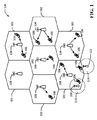
図1は、ネットワークアーキテクチャにおけるアクセスネットワーク100の一般化された例を示す図である。この例では、アクセスネットワーク100は、いくつかのセルラー領域(セル)102、110、114に分割される。各セルラー領域102、110、114は、基地局(BS)104、108、112を含む。1つまたは複数の低電力クラスBS108、112は、それぞれ1つまたは複数の他のセルラー領域(セル)102と重複するセルラー領域110、114をそれぞれ有してもよい。低電力クラスBS108、112によってサービスされるセルラー領域110、114は、たとえばフェムトセル、ピコセル、またはマイクロセルであってもよい。
FIG. 1 is a diagram illustrating a generalized example of an
概して、各基地局(BS)104、108、112は、デバイス間ネットワークおよび/またはメッシュネットワークにおける発展型ノードB(eNB)、ホームeNB、アクセスポイント、またはユーザ機器(UE)106であってもよい。BS104、108、112のうちの1つまたは複数は、当業者によって、基地局、基地トランシーバ局、無線基地局、無線トランシーバ、トランシーバ機能、基本サービスセット(BSS)、拡張サービスセット(ESS)と呼ばれるか、または何らかの他の適切な用語で呼ばれることもある。BS104、108、112は、1つまたは複数のUE106に関するネットワークへのアクセスポイントを構成する。UE106の例には、携帯電話、スマートフォン、セッション開始プロトコル(SIP)電話、ラップトップ、携帯情報端末(PDA)、衛星無線、全地球測位システム、マルチメディアデバイス、ビデオデバイス、デジタルオーディオプレーヤ(たとえば、MP3プレーヤ)、カメラ、ゲームコンソール、または同様に機能する他の任意のデバイスがある。UE106は、当業者によって、モバイルノード、移動局、加入者局、モバイルユニット、加入者ユニット、ワイヤレスユニット、リモートユニット、モバイルデバイス、ワイヤレスデバイス、ワイヤレス通信デバイス、リモートデバイス、モバイル加入者局、アクセス端末、モバイル端末、ワイヤレス端末、リモート端末、ハンドセット、ユーザエージェント、モバイルクライアント、クライアントと呼ばれるか、または他の何らかの適切な用語で呼ばれることもある。
In general, each base station (BS) 104, 108, 112 may be an evolved Node B (eNB) in a device-to-device network and/or a mesh network, a home eNB, an access point, or a user equipment (UE) 106. .. One or more of
いくつかの例では、BS104、108、112は、キャリア上のリソースを管理して、セルラーネットワーク100内の1つまたは複数のUE106などの、チャネルの他のユーザにリソースを割り当てる。さらに、BS104、108、112は、無線ベアラ制御と、承認制御と、モビリティ制御と、スケジューリングと、セキュリティと、モバイルコアネットワークなどのリモートネットワーク内の集中型コントローラおよび/またはゲートウェイへの接続性とを含むすべての無線関係機能を担当してもよい。
In some examples,
アクセスネットワーク100によって使用される変調および多元接続方式は、展開される特定の電気通信規格に応じて異なってもよい。ロングタームエボリューション(LTE)適用例では、周波数分割複信(FDD)と時分割複信(TDD)の両方をサポートするためにダウンリンク(DL)上ではOFDMが使用され、アップリンク(UL)上ではSC-FDMAが使用される。当業者が以下の詳細な説明から容易に諒解するように、本明細書において提示する様々な概念は、LTE適用例に好適である。しかしながら、これらの概念は、他の変調技法および多元接続技法を利用する他の電気通信規格に容易に拡張される場合がある。例として、これらの概念は、エボリューションデータオプティマイズド(EV-DO)またはウルトラモバイルブロードバンド(UMB)に拡張されてもよい。EV-DOおよびUMBは、CDMA2000規格ファミリーの一部として第3世代パートナーシッププロジェクト2(3GPP2)によって公表されたエアインターフェース規格であり、移動局のブロードバンドインターネットアクセスを可能にするためにCDMAを利用する。これらの概念はまた、広帯域CDMA(W-CDMA)およびTD-SCDMAなどのCDMAの他の変形形態を採用するユニバーサル地上無線アクセス(UTRA)、TDMAを採用するGlobal System for Mobile Communications(GSM(登録商標))、ならびにOFDMAを採用する発展型UTRA(E-UTRA)、IEEE802.11(Wi-Fi)、IEEE802.16(WiMAX)、IEEE802.20、およびFlash-OFDMに拡張されてもよい。UTRA、E-UTRA、UMTS、LTE、およびGSM(登録商標)については、3GPP団体による文書に記載されている。CDMA2000およびUMBは、3GPP2団体による文書に記載されている。用いられる実際のワイヤレス通信規格および多元接続技術は、特定の適用例およびシステムに課される全体的な設計制約に依存する。
The modulation and multiple access schemes used by
本開示のいくつかの態様では、アクセスネットワーク100は、統合アクセスバックホール(IAB)ネットワークなどのバックホールネットワークと重複してもよい。すなわち、BS104、108、112のうちのいくつかまたはすべてがIABノード200(図2〜図8参照)であってもよく、したがって、IABネットワークを介して互いに通信してもよい。
In some aspects of the disclosure,
図2は、本開示のいくつかの態様において利用される場合があるネットワーク構成の一例の高レベル図を示す概略図である。この例では、ローカルバックホールネットワーク202、メインバックホールネットワーク204、およびモバイルコアネットワーク(本明細書では単に「コアネットワーク」と呼ぶ)などのリモートネットワーク206を含む3つのネットワークは概して、クラウドとして表現される。クラウドによる表現は、外界には、入力ノードと出力ノードとの間に1つまたは複数の経路が存在する場合があること以外、ネットワークの内部詳細がほとんどまたはまったくわからない場合があることを意味するものである。
FIG. 2 is a schematic diagram illustrating a high-level diagram of an example network configuration that may be utilized in some aspects of the present disclosure. In this example, three networks, including a
いくつかの例では、メインバックホールネットワーク204は、従来のT1回線交換網、キャリアイーサネット(登録商標)ネットワーク、イーサネット(登録商標)と非同期転送モード(ATM)、T1-E1およびフレームリレーなどの他のレイヤ2技術とのハイブリッド、インターネットプロトコル(IP)/イーサネット(登録商標)ネットワーク、またはフラットインターネットプロトコル(IP)ネットワークなどのワイヤラインネットワークに相当してもよい。さらに、以下でさらに説明するように、ローカルバックホールネットワーク202はIABネットワークに相当してもよい。そのようなIABネットワークでは、アクセスリンクとバックホールリンクの両方にワイヤレススペクトルが使用されてもよい。
In some examples, the
いくつかの例では、ローカルバックホールネットワーク202とメインバックホールネットワーク204はどちらもインターネットプロトコル(IP)ネットワークである。他の例では、ローカルバックホールネットワーク202はIPネットワークであり、一方、メインバックホールネットワーク204は別の種類のネットワークである。各バックホールネットワークネットワーク202および204は一般に、フォワーディングプレーン上でIPまたはIEEE802.1などのそれぞれのネットワーキングプロトコルをサポートし、制御プレーン上でそれぞれのルーティングプロトコルをサポートし得る。
In some examples, both
図2に示す例では、ローカルバックホールネットワーク202とメインバックホールネットワーク204が、図示のように境界ノード208と境界ノード210を含む複数の境界ノードによって相互接続される。これらの境界ノード208および210は一般に、メインバックホールネットワーク204を介してコアネットワーク206とローカルバックホールネットワーク202との間のネットワーク接続性を確立する。さらに、ローカルバックホールネットワーク202は、各々が1つまたは複数のユーザ機器(UE)220とのワイヤレスリンクを有する場合がある複数のアクセスポイントまたは基地局(BS)214、216、218をサポートするように示されている。
In the example shown in FIG. 2,
概して、基地局214、216、218は、UE220へのワイヤレスアクセスをサポートして可能にし、ローカルバックホールネットワーク202およびメインバックホールネットワーク204を介したコアネットワーク206へのトンネル(たとえば、トンネル224)を生成し、UE220とBS214、216、218とそれぞれのトンネル224との間のそれぞれのワイヤレスアクセスリンクおよびエアインターフェース間のトラフィックフローを中継することによって、アクセストラフィックを含むすべてのトラフィックフローをUE220とコアネットワーク206との間で効果的に伝達する働きをしてもよい。いくつかの例では、2つ以上のトンネル224が各UE220に割り振られてもよい。
In general,
トンネル224のエンドポイントは、BS216上に存在するローカルアンカーとコアネットワーク206における制御プレーンノード222上に存在するグローバルアンカーとを含む。トンネル224を生成して管理するのに様々なプロトコルが使用されてもよい。限定ではなく、例として、モバイルIPv4、モバイルIPv6、プロキシモバイルIP、3GPP W-CDMA、および/または3GPPのシステムアーキテクチャ評価(SAE)などのプロトコルが使用されてもよい。
The endpoints of
プロキシモバイルIPでは、たとえば、トンネル224は、モビリティアクセスゲートウェイ(MAG)と呼ばれBS216上に存在するローカルモビリティアンカーと、ローカルモビリティアンカー(LMA)と呼ばれコアネットワーク206における制御プレーンノード222上に存在するグローバルモビリティアンカーとの間に確立されてもよい。SAEでは、トンネル224は、ローカルモビリティアンカーを保持するeNB(BS216)と、コアネットワーク206におけるグローバルモビリティアンカーを表すサービングゲートウェイ(S-GW)(制御プレーンノード222)との間に確立されてもよい。トンネルは、SAEにおいて使用されているIP-GTP(汎用パケット無線サービストンネリングプロトコル)-UDP(ユーザデータグラムプロトコル)-IPカプセル化を介して実現することができる。他の例では、IP-GRE(汎用ルーティングカプセル化)-IP、プレーンIPインIPカプセル化、IPsec(インターネットプロトコルセキュリティ)トンネル、またはパケットカプセル化および非カプセル化を介した階層化を使用する任意の他のタイプのトンネルが使用されてもよい。
In Proxy Mobile IP, for example, a
図3は、図2のローカルバックホールネットワーク202の一例のさらなる詳細を示す。図3に示す例では、ローカルバックホールネットワーク202は統合アクセスバックホール(IAB)ネットワーク226であってもよい。しかし、これは一例に過ぎず、本開示の態様は、他のタイプのローカルバックホールネットワークに適用されてもよく、IABネットワークには限定されない。
FIG. 3 shows further details of an example of the
IABネットワーク226は、アクセスポイント、基地局(BS)、eNB、またはUEおよびアクセストラフィックのバックホールに関するアクセスをサポートするのにワイヤレススペクトル(たとえば、無線周波数(RF)スペクトル)を利用するその他のノードであってもよい複数のIABノード214、216、218、228、および230を含む。これは、ワイヤレスセルフバックホールと呼ばれることがある。そのようなワイヤレスセルフバックホールは、密度の高いスモールセルネットワークの迅速で容易なデプロイメントを可能にすることができる。すなわち、各々の新しいBSデプロイメントにそれ自体の配線接続されたバックホール接続を備えることを要求するのではなく、BSとUEとの間の通信に利用されるワイヤレススペクトルが、IABネットワーク226を形成するために任意の数のIABノード間のバックホール通信に活用されてもよい。
The
たとえば、図3に示すように、アクセストラフィックが、ワイヤレスバックホールリンク232を介してIABノード216とIABノード228との間に迂回され、ワイヤレスバックホールリンク234を介してIABノード228と境界ノード208との間に迂回されてもよい。IABノード214、216、218、228、および230のうちのいくつかまたはすべてがワイヤードバックホールリンク(たとえば、ファイバー、同軸ケーブル、イーサネット(登録商標)、銅線など)および/またはマイクロ波バックホールリンクを介して接続されてもよい。したがって、IABネットワーク226は、ワイヤード/マイクロ波バックホールトラフィックとワイヤレスバックホールトラフィックの両方をサポートしてもよい。一例では、それぞれのIABノード(たとえば、IABノード216および228)間の物理エアインターフェースおよびIABノード216とUE220との間の物理エアインターフェースは、IEEE802.11エアインターフェースであってもよい。
For example, as shown in FIG. 3, access traffic is diverted between
図3に示す境界ノード208および210はIABノードであってもよい。しかし、IABネットワーク226における他のIABノードとは異なり、境界ノード208および210は、メインバックホールネットワーク204への通信リンクを確立してもよい。たとえば、境界ノード208、210は、メインバックホールネットワーク204へのワイヤード(たとえば、ファイバー、同軸ケーブル、イーサネット(登録商標)、銅線)バックホールリンク、マイクロ波バックホールリンク、または他の適切なバックホールリンクを含んでもよい。
The
概して、図3に示す例において、IABバックホールネットワーク226における各IABノードは、1つまたは複数のUE220へのワイヤレスアクセスのためのエアインターフェースを構成する場合があるBSを表してもよい。IABノードのうちのいくつかがマクロセル基地局に相当してもよく、いくつかがマイクロセルまたはピコセルに相当してもよく、一方、他のIABノードがフェムトセルまたは他の近距離低電力セルに相当してもよい。
In general, in the example shown in FIG. 3, each IAB node in
例示的な実装形態では、境界ノード208および境界ノード210がマクロセル基地局に相当してもよく、一方、IABネットワーク226における他のBS(すなわち、IABノード214、216、218、228、および230)が、ネットワークを、場合によっては境界ノードのみから利用可能なものを超えて拡張するようにデプロイされたスモールセルまたは低電力セルに相当してもよい。このようにして、ネットワーク事業者は、そのアクセスネットワークを比較的低コストでかつ簡単に構築し、低電力IABノードのセットからメッシュトポロジー(または場合によっては、構成済みのネットワーク)を形成する場合があり、IABノードの各々がさらに、アクセストラフィックを迂回させるように動作してもよい。これらのスモールセルまたは低電力セルは一般に、小さい占有面積を有し、各スモールセルは大容量を実現することができる場合があるが、所与の時間に少数のUEにしかサービスしないことがある。したがって、アクセストラフィックをLABバックホールネットワークを通して境界ノード208または210に自動的に迂回させるのに過剰な容量が利用される場合がある。いくつかの例では、IABネットワーク226はIEEE802.11xメッシュネットワークであってもよい。
In the exemplary implementation,
したがって、図示のUE220などの所与のUEとコアネットワーク206との間で伝達されるアクセストラフィックは、トンネル224を通してコアネットワーク206と通信できるようにIABネットワーク226をメインバックホールネットワーク204と協働して利用してもよい。物理層レイヤでは、ワイヤレスアクセスリンクを介したUE220からIABノード216へのアクセストラフィックが、バックホールリンク(ワイヤードまたはワイヤレス)を介して隣接するIABノード230に中継または転送されてもよく、IABノード230はこのアクセストラフィックをさらに別のIABノード(図示せず)に転送してもよく、このことは、この情報トラフィックが図3の境界ノード210などの境界ノードに達するまで任意の回数だけ継続する。境界ノード210は、アクセストラフィックを含むトラフィックフローをメインバックホールネットワーク204を介してコアネットワーク206における制御プレーンノード222に転送する。反対方向では、物理レイヤにおいて、アクセストラフィックは、コアネットワーク206からメインバックホールネットワーク204を通って境界ノード210に至る適切な経路を使用してもよく、次いでIABネットワーク226における、IABノード230を含む任意の数のIABノードを通過してUEのローカルアンカー(IABノード216)、すなわち、UE220用のサービングBSに到達してもよい。
Thus, access traffic carried between a given UE, such as the
IABノード216と制御プレーンノード222との間においてアクセストラフィックが通過する物理経路を本明細書ではルーティング経路と呼ぶ。図3の図示の例では、UE220とコアネットワーク206との間のすべてのアクセストラフィックが、境界ノード210を通してルーティングされる。したがって、コアネットワーク206からUE220に向かうアクセストラフィックは、メインバックホールネットワーク204を通過する経路236を使用する。IABネットワーク226を通過する経路の残りの部分は、ルーティング経路238として示される。もちろん、図示のルーティング経路236/238は、アクセストラフィックが使用する場合がある1つの考えられる経路のみを表し、アクセストラフィックは、IABネットワーク226における任意の境界ノードを通過してもよい。
A physical route through which access traffic passes between the
IABネットワーク226は、IABネットワーク226がメインバックホールネットワーク204にアドバタイズするネットワークアドレスプレフィックス(たとえば、プレフィックスA)によってアドレス指定されてもよい。パケットをUE220との間でルーティングする場合、IABノード216は、ネットワークアドレスプレフィックスを含むトンネルエンドポイントアドレスを利用する。たとえば、UE220に関するトンネルエンドポイントアドレスは「A6」であってもよい。その場合、UE220に関するダウンストリームパケットは、トンネル224を介してメインバックホールネットワーク204およびIABネットワーク226を通過する際にパケットヘッダ内の宛先アドレスとして「A6」を伝達する。IAB216は、ダウンストリームパケットを受信すると、トンネルヘッダを除去し、パケットをワイヤレスリンクを介してUE220に転送してもよい。
複数の境界ノード208および210は、IABネットワーク226にある程度の冗長性をもたらすメインバックホールネットワーク206とのそれぞれの接続を有するように示されているが、IABネットワーク226が、メインバックホールネットワーク226とともに維持するリンク冗長性を利用できないと問題が生じる。たとえば、IABネットワーク226が、ホストルートまたは負荷関連情報などの十分に正確なルーティング情報をメインバックホールネットワーク204に伝達することができない場合、アクセストラフィックを境界ノード208、210間で再ルーティングすることができない場合がある。
Although the plurality of
IABネットワーク216とメインバックホールネットワーク204との間のルーティング情報の転送に対する制限は、様々な要因の結果として生じることがある。たとえば、両方のネットワーク204および226が、正確なネットワークトポロジーまたは性能情報を互いに共有することを望まないそれぞれに異なるネットワーク事業者によって所有される場合がある。別の例として、メインバックホールネットワーク204内で使用されるルーティングプロトコルは、未知である場合があり、あるいは負荷関連情報をサポートしないことがある。メインバックホールネットワーク204が静的に構成され、したがって、いかなるルーティングプロトコルをサポートしないことも考えられる。バックホールネットワーク204および226の一方または両方が、そのネットワークを他方のトポロジーおよび負荷動特性から分離することを望む場合もある。たとえば、メインバックホールネットワーク204は、IABネットワーク226におけるワイヤレスリンクに対する変更に起因するIABネットワーク226からの高速ルーティング更新から分離される必要がある場合がある。
Limitations on the transfer of routing information between
上記のシナリオのいずれにおいても、メインバックホールネットワーク204は、境界ノードのうちの1つ(たとえば、境界ノード210)をコアネットワーク206とIABネットワーク226との間のすべてのアクセストラフィックに関する入口/出口点として選択してもよい。図3の図示の例では、コアネットワーク206からIABネットワーク226に至るすべてのアクセストラフィックにルーティング経路236が使用される場合、ルーティング経路238は、事実上、アクセストラフィックがUE220に到達するのに利用できる唯一のルーティング経路である場合がある。そのような構成によって、IABネットワーク226ではローカルリンク障害またはトラフィック輻輳がより生じやすくなる。たとえば、図示のIABノード210および230の接続性および負荷条件に基づいて、アクセストラフィックをUE220との間で配信することができないことがあり、あるいはアクセストラフィックにパケット損失または遅延が発生する場合があり、性能劣化が生じる。
In any of the above scenarios, the
たとえば、IABネットワーク226におけるルーティング経路238上でリンク障害が生じた場合、唯一の代替ルーティング経路は境界ノード208を通過する。しかし、この切替えを行うには、IABネットワーク226が、上述のようにサポートされない場合があるホスト固有の接続性変更をメインバックホールネットワーク204に伝達する必要がある。別のオプションとして、境界ノード210は、「プレフィックスA」をメインバックホールネットワークにアドバタイズするのを停止することができる。しかし、この場合、境界ノード210を介してのみサポートされる場合がある他のIABノード(たとえば、IABノード218)との接続性が影響を受ける。
For example, if a link failure occurs on
したがって、本開示の1つまたは複数の態様は、IABネットワークにおけるリンク障害またはトラフィック輻輳などの場合にトラフィックルーティングのロバストな移行を可能にする。図4は、IABネットワークが2つの重複するネットワークルーティングドメインによって構成されるネットワーク構成を示す。図4の例では、重複するネットワークルーティングドメインには第1のネットワークルーティングドメイン240(点線によって示されている)と第2のネットワークルーティングドメイン242(二点鎖線によって示されている)とが含まれる。各ネットワークルーティングドメイン240および242はそれぞれ、異なる境界ノード208および210に属する。他の例では、各ネットワークルーティングドメイン240は2つ以上の境界ノードに属してもよい。
Accordingly, one or more aspects of the present disclosure enable a robust transition of traffic routing in the event of link failure or traffic congestion in IAB networks. Figure 4 shows a network configuration where the IAB network is composed of two overlapping network routing domains. In the example of FIG. 4, the overlapping network routing domains include a first network routing domain 240 (shown by the dashed line) and a second network routing domain 242 (shown by the dashed line). . Each
各ネットワークルーティングドメイン240および242は、異なるネットワークアドレスプレフィックスによってアドレス指定されてもよい。たとえば、図4に示すように、ネットワークルーティングドメイン240はネットワークアドレスプレフィックス「A」によってアドレス指定され、一方、ネットワークルーティングドメイン242はネットワークアドレスプレフィックス「B」によってアドレス指定される。各境界ノード208および210は、そのネットワークアドレスプレフィックスをメインバックホールネットワーク204にアドバタイズする。したがって、ネットワークルーティングドメイン240と242との間の重複エリアに存在するIABノード214、216、218、228、および230は、ネットワークルーティングドメイン240および242ごとに1つ設けられた2つのトンネルエンドポイントアドレスを取得する。たとえば、IABノード216は、ネットワークルーティングドメイン242におけるトンネルエンドポイントアドレス「A6」およびネットワークルーティングドメイン240におけるトンネルエンドポイントアドレス「B3」を保持してもよい。いくつかの例では、トンネルエンドポイントアドレスはIPアドレスである。
Each
2つのネットワークルーティングドメイン240および242に関するアクセストラフィックを分離する場合、IABノード(たとえば、IABノード216)は、(図8に関連して以下でより詳細に説明するように)ネットワークルーティングドメイン240および242の各々について別個の論理インターフェースを生成してもよい。各論理インターフェースは、それぞれの物理リンク(たとえば、ワイヤレスリンク、マイクロ波リンク、またはファイバー、同軸ケーブル、イーサネット(登録商標)、銅線、および/または他のワイヤード通信リンクなどのワイヤードリンク)に結合されたそれぞれの物理インターフェース(すなわち、ネットワークインターフェースカード)上に配置されてもよい。さらに、各物理リンク上には、各々が論理インターフェースのうちの1つに対応する1つまたは複数の論理リンクが配置されてもよい。一例では、ネットワークルーティングドメイン240および242の各々は、物理(すなわち、ワイヤレスまたはワイヤード)リンクを共有するトポロジー的に異なり互いに独立したルーティングネットワークであってもよい。したがって、物理リンクを論理レベルにおいて2つ以上のネットワークルーティングドメインによって利用するのを可能にするために複数の論理リンクが生成され各物理リンク上に配置されてもよい。図4の図示の例では、物理リンク244などの物理リンクのいくつかは、2つのネットワークルーティングドメイン240および242を実装するために2つの論理リンクを備えて配置される。
When segregating access traffic for two
一例では、IABノード208、210、214、216、218、228、230は、バックホール上のローカルエリアネットワーク(LAN)ベースの転送およびネットワークルーティングドメイン240とネットワークルーティングドメイン242を区別するための仮想ローカルエリアネットワーク(VLAN)タグを使用してもよい。このように、各物理リンクは複数の論理リンクをサポートすることができる。一例では、各転送ノード(IABノード)はVLANスイッチまたはブリッジを表す。
In one example,
別の例では、IABノード208、210、214、216、218、228、230は、バックホール上のIPベースの転送を利用してもよい。この例でも、ネットワークルーティングドメイン240と、ネットワークルーティングドメイン242と、各物理リンク上の論理リンクを区別するためにVLANタグが使用されてもよい。一例では、各転送ノード(IABノード)はIPルータを表してもよい。
In another example,
別個のネットワークルーティングドメイン242および244を用いると、上述のリンク障害問題シナリオが対処される場合がある。通常動作では、図4に示すように、コアネットワーク206におけるグローバルアンカーまたは制御プレーンノード222が、ルーティング経路236に沿ってUE220を宛先とするアクセストラフィックを境界ノード210に属するネットワークルーティングドメイン242に転送してもよい。境界ノード210はそれに応じて、このトラフィックをルーティング経路238に沿ってUE220の方へ転送してもよい。
The use of separate
しかし、次に図5を参照すると、ルーティング経路238に沿って(たとえば、リンク244において)リンク障害が生じた場合、境界ノード210に配信されたトラフィックを、ローカルアンカーまたはUE220にサービスするIABノード216に配信するのに利用することはできない。そのようなリンク障害は、いくつかの理由で生じる場合がある。たとえば、リンク244がワイヤレスリンクである場合、障害物または干渉源がワイヤレスリンクに障害を生じさせる場合がある。リンク244に障害が生じると、もはやサービングIABノード216と境界ノード210との接続性が失われる。
However, referring now to FIG. 5, in the event of a link failure along routing path 238 (eg, at link 244),
IABノード216は、2つのネットワークルーティングドメイン240および242間の重複領域内に位置するので、リンク244に障害が生じると、ローカルアンカー(IABノード216)とグローバルアンカー(制御プレーンノード222)との間のトンネル224内のトラフィックフローがネットワークルーティングドメイン242からネットワークルーティングドメイン240に移管される場合がある。トラフィックフローの移行は、異なるエンドポイントを有する新しいトンネルにトラフィックフローを再割当てするか、または同じトンネルを異なるトンネルエンドポイントに移管することによって実現されてもよい。理解しやすいように、トラフィックフローを第1のトンネルから第2のトンネルに移管することを、いずれかのタイプのトラフィックフローの移行を包含することと見なす。
The
図5における図示の例では、トラフィックフローは、アクセストラフィックを境界ノード208を通して再転送することによって移管されてもよい。したがって、コアネットワーク206からUE220に向かうアクセストラフィックは、メインバックホールネットワーク204を通って境界ノード208に向かうルーティング経路246に切り替えられてもよい。境界ノード208は次いで、アクセストラフィックをルーティング経路248上でIABネットワークを通ってサービングIABノード216に至るようにルーティングしてもよい。
In the illustrated example in FIG. 5, traffic flow may be transferred by redirecting access traffic through
トラフィックフローの移行を容易にするために、上述のように、ローカルアンカー(IABノード216)に対して2つのネットワークアドレス(本明細書ではトンネルエンドポイントアドレスとも呼ばれる)がプロビジョニングされ、この場合、一方のネットワークアドレスは第1のネットワークルーティングドメイン240に対応し、一方のネットワークアドレスは第2のネットワークルーティングドメイン242に対応する。たとえば、IABノード216は、ネットワークルーティングドメイン242におけるトンネルエンドポイントアドレス「A6」およびネットワークルーティングドメイン240におけるトンネルエンドポイントアドレス「B3」を保持してもよい。
To facilitate traffic flow transitions, two network addresses (also referred to herein as tunnel endpoint addresses) are provisioned for the local anchor (IAB node 216), in this case one Network address corresponds to the first
アクセストラフィックの移行を開始する場合、IABノード216は、経路更新メッセージをネットワークルーティングドメイン240を介してコアネットワーク206における制御プレーンノード222に送り、アクセストラフィックのフローをトンネルエンドポイントアドレスA6に対応する現在のトンネルからトンネルエンドポイントアドレスB3に対応する新しいトンネルに切り替えるよう制御プレーンノード222に要求してもよい。トンネルエンドポイントアドレスB3は、境界ノード208を含む第1のネットワークルーティングドメイン240に属するので、すべてのアクセストラフィックがメインバックホールネットワーク204から境界ノード208にルーティングされる場合がある。このようにして、UE220は、トンネル移行を認識しなくてもよく、かつ引き続きコアネットワーク206と通信してもよく、一方、ローカルアンカー(IABノード216)は、複数のネットワークルーティングドメインおよびIPアドレスを利用してトンネル224を移管し、IABネットワークにおけるリンク障害を回避する。
When initiating a transition of access traffic, the
一例では、トラフィックフローをネットワークルーティングドメイン242からネットワークルーティングドメイン240に移管するためにトンネル224がプロキシモバイルIPを使用して管理される場合、IABノード216上に存在するMAGが、制御プレーンノード222上に存在するLMAにバインディング更新メッセージを送ってもよい。バインディング更新メッセージは、たとえば、このフローに関してMAGによって使用されるフロー識別子(ID)および新しいIPアドレス(たとえば、アドレスA6)を含んでもよい。
In one example, if
別の例では、トラフィックフローをネットワークルーティングドメイン242からネットワークルーティングドメイン240に移管するためにトンネル224がSAEを使用して管理される場合、eNB216がS1-AP経路切替えメッセージをコアネットワーク206におけるモビリティ管理エンティティ(MME)に送ってもよく、次いでMMEがベアラ更新メッセージをS-GW(制御プレーンノード222)に送る。S1-AP経路切替えメッセージは、たとえば、このベアラに関してeNBによって使用されるベアラ(フローID)および新しいIPアドレス(たとえば、アドレスA6)を含んでもよい。
In another example, if the
各IABノードは、これらの重複するネットワークドメイン240および242を生成した後、独立したネットワークルーティングドメインに対応する独立したIPアドレスを介して境界ノードのより大きいセット(2つ以上の境界ノード)にアクセスしてもよい。各IABノードは、各ネットワークルーティングドメイン上で実行されるそれぞれのルーティングプロトコルから各境界ノードとの接続性に関して学習してもよい。ルーティングプロトコルは、ネットワークノード(ルータ)が、ネットワークノード自体が通信ネットワーク上の任意の2つのノード間のルートを選択するのを可能にする情報をどのように普及させるかを指定する。各ルータは一般に、それに直接取り付けられたネットワークノードに関する知識を有する。ルーティングプロトコルは、この情報をまずネットワーク全体にわたってピアノード間で共有させる。このようにして、ルータはネットワークのトポロジーの知識を得る。ルーティングプロトコルは、たとえば距離ベクトルプロトコル、リンク状態プロトコル、または他のルーティングプロトコルを含んでもよい。
Each IAB node will generate these overlapping
したがって、IABノード216などのIABノードは、第1のネットワークルーティングドメイン240上で実行される第1のルーティングプロトコルを使用する境界ノード208への第1のルートのステータス、およびネットワークルーティングドメイン242上で実行される第2のルーティングプロトコルを使用する境界ノード210への第2のルートのステータスを認識してもよい。このルート情報によって、IABノード216は、どちらの境界ノード208、210がより良好な通信(たとえば、スループット、帯域幅)を可能にするかを決定することができる。
Thus, an IAB node, such as
図6は、上述のアルゴリズムおよび手順を利用して対処される場合があるIABネットワークにおける不平衡負荷分散を伴うシナリオを示す。図6に示す図示の例では、比較的多数のUE220a〜220eが、互いに比較的近接しているIABノード216および218にアクセスする。たとえば、UE220aおよび220bがIABノード216にアクセスし、一方、UE220c、220d、および220eがIABノード218にアクセスする。
FIG. 6 illustrates a scenario with unbalanced load balancing in an IAB network that may be addressed using the algorithms and procedures described above. In the illustrated example shown in FIG. 6, a relatively large number of UEs 220a-220e
メインバックホールネットワーク204は、同じネットワークルーティングドメイン242および対応する境界ノード210を介してUE220a〜UE220eのすべてについてアクセストラフィックを転送してもよい。たとえば、コアネットワーク206からUE220aおよび220bに向かうアクセストラフィックは、メインバックホールネットワーク204を通って境界ノード210に至るルーティング経路250を使用し、次いでIABネットワークを通るルーティング経路252を使用してもよい。さらに、コアネットワーク206からUE220c、220d、および220eに向かうアクセストラフィックは、メインバックホールネットワーク204を通って境界ノード210に至るルーティング経路254を使用し、次いでIABネットワークを通るルーティング経路256を使用してもよい。
The
図6に示す状況では、ネットワークルーティングドメイン242上のトラフィックの量が多いので、境界ノード210はローカルトラフィック過負荷状態を経験する場合がある(たとえば、物理リンク上のトラフィック通信量がしきい値を超えた場合)。図示の例では、境界ノード210から隣接するIABノード230へのバックホールリンク258がルーティング経路252上とルーティング経路256上の両方でアクセストラフィックを伝達するので、バックホールリンク258は、過負荷状態になり、下流ノード上のスループットが影響を受ける。バックホールリンク258は、図示のようにワイヤード物理リンクであっても、あるいはワイヤレス物理リンクであってもよい。スペクトルの利用可能性が限定されていることに起因してワイヤレスリンク容量を容易に増大させるのは不可能であるので、過負荷状態は、ワイヤレスバックホール物理リンクを使用する際に生じやすい場合がある。
In the situation shown in FIG. 6, the
したがって、本開示の一態様によれば、IABネットワークなどのネットワーク内のローカルトラフィック過負荷状態を軽減するのに負荷平衡が利用されてもよい。図7に示すように、IABノード216および218は2つのネットワークルーティングドメイン240とネットワークルーティングドメイン242との間の重複領域内に位置するので、各IABノード216および218に対して2つのトンネルエンドポイントアドレスがプロビジョニングされ、この場合、一方のトンネルエンドポイントアドレスは第1のネットワークルーティングドメイン240に対応し、一方のトンネルエンドポイントアドレスは第2のネットワークルーティングドメイン242に対応する。たとえば、IABノード216は、ネットワークルーティングドメイン242におけるトンネルエンドポイントアドレス「A6」およびネットワークルーティングドメイン240におけるトンネルエンドポイントアドレス「B3」を保持してもよい。同様に、IABノード218は、ネットワークルーティングドメイン242におけるトンネルエンドポイントアドレス「A5」およびネットワークルーティングドメイン240におけるトンネルエンドポイントアドレス「B8」を保持してもよい。
Thus, according to one aspect of the present disclosure, load balancing may be utilized to mitigate local traffic overload conditions in networks such as IAB networks. As shown in FIG. 7,
IABノード216など、IABノードのうちの1つまたは複数は、境界ノード210に過負荷状態が存在すると決定した場合、1つまたは複数のトラフィックフロー(各々がUE220aおよび220bのうちの一方に関連する)を選択してネットワークルーティングドメイン242からネットワークルーティングドメイン240に移管する。図7における図示の例では、IABノード216は、アクセストラフィックを境界ノード208を通して再転送することによってUE220aおよび220bに関連するトラフィックフローを移管してもよい。したがって、コアネットワーク206からUE220aおよび220bに向かうアクセストラフィックは、メインバックホールネットワーク204を通って境界ノード208に向かうルーティング経路258に切り替えられてもよい。境界ノード208は次いで、アクセストラフィックをルーティング経路260上でIABネットワークを通ってサービングIABノード216に至るようにルーティングしてもよい。
One or more of the IAB nodes, such as
アクセストラフィックの移行を開始する場合、IABノード216は、経路更新メッセージをネットワークルーティングドメイン240(またはネットワークルーティングドメイン242)を介してコアネットワーク206における制御プレーンノード222に送り、アクセストラフィックのフローをトンネルエンドポイントアドレスA6に対応する現在のトンネルからトンネルエンドポイントアドレスB3に対応する新しいトンネルに切り替えるよう制御プレーンノード222に要求してもよい。トンネルエンドポイントアドレスB3は、境界ノード208を含む第1のネットワークルーティングドメイン240に属するので、すべてのアクセストラフィックがメインバックホールネットワーク204から境界ノード208にルーティングされる場合がある。このようにして、UE220aおよび220bは、トンネル移行を認識しなくてもよく、かつ引き続きコアネットワーク206と通信してもよく、一方、ローカルアンカー(IABノード216)は、複数のネットワークルーティングドメインおよびIPアドレスを利用してトンネルを移管し、場合によっては境界ノード210からの送信において生じる場合がある輻輳をある程度緩和する。
When initiating a transition of access traffic, the
一例では、各IABノード216および218は、それがサポートする(2つのネットワークルーティングドメイン240および242に対応する)2つのルーティングプロトコルからルーティングメッセージを受信してもよい。各IABノード216および218は、ルーティングメッセージからリンク情報およびルート情報を導出し、このリンク情報およびルート情報を使用して、IABノードによってサービスされる1つまたは複数のトラフィックフローを現在のネットワークルーティングドメインから別のネットワークルーティングドメインに移管すべきであるかどうかを決定してもよい。リンク情報は、たとえば、1つまたは複数のリンクメトリックを含んでもよい。リンクメトリックは、信号強度、信号対雑音比(SNR)または信号干渉対雑音比(SINR)測定値、雑音増加、干渉、経路損失、スループット推定値、負荷推定値、および/またはレイテンシ推定値などの物理リンク品質に関係する情報を含む。リンクメトリックは、ピアIABノードから受信されたビーコン、パイロット信号、または発見信号から導出されてもよい。
In one example, each
ルート情報は、たとえば、1つまたは複数のルートメトリックを含んでもよい。ルートメトリックは、リンクメトリックのセットに関係する情報を伝達してもよく、この場合、リンクは、IABネットワークのネットワークルーティングドメイン内の特定のルートに関する。たとえば、リンクメトリックのセットは、ルートに関係する総計情報を導出してルートメトリックを形成するのに使用されてもよい。ルートメトリックも、ホップカウント、ルートに沿った最小スループット値、総計ルートレイテンシ、および/またはルートに沿ったボトルネック負荷値などの、ルートに関係する総計情報を伝達してもよい。ルートメトリックは、たとえば距離ベクトルプロトコル、リンク状態プロトコル、または他のルーティングプロトコルを介して配信されるルート更新から得られるかまたは導出されてもよい。ルートメトリックは、隣接するネットワークへのルート、コアネットワーク206などのリモートネットワークへのルート、またはデフォルトルートに関する。
The route information may include, for example, one or more route metrics. The route metric may convey information related to a set of link metrics, where the link relates to a particular route within the network routing domain of the IAB network. For example, the set of link metrics may be used to derive aggregate information related to a route to form a route metric. The route metric may also convey aggregate information related to the route, such as hop count, minimum throughput value along the route, aggregate route latency, and/or bottleneck load value along the route. The route metric may be obtained or derived from route updates delivered via distance vector protocols, link state protocols, or other routing protocols, for example. Route metrics relate to routes to adjacent networks, routes to remote networks such as
一実施形態では、ルーティングプロトコルは、IABノード216などのIABノードが、ルーティングプロトコルをサポートするネットワークルーティングドメインを介して隣接するネットワークへのコストメトリックを導出するのを可能にする。コストメトリックは、ある特性評価内の負荷、スループットなどを表すことのできるグレードを提示してもよい。したがって、IABノード216は、ネットワークルーティングドメイン240を介してメインバックホールネットワーク204などの隣接するネットワークへのコスト(cost_A)を取得し、ネットワークルーティングドメイン242を介して同じ隣接するネットワークへの別のコスト(cost_B)を取得する。コストメトリックは、ホップカウントまたは隣接するネットワークへの経路に沿ったリンク容量の逆数の和に相当してもよく、この場合、リンク容量は、リンクの公称容量または現在のリンク負荷を考慮した実際の容量を指す場合がある。
In one embodiment, the routing protocol enables IAB nodes, such as
IABノード216は、各ネットワークルーティングドメインのそれぞれのコストメトリックに基づいてすべてのトラフィックフローまたはトラフィックフローのセット用のネットワークルーティングドメインを選択してもよい。たとえば、IABノード216は、cost_A<cost_Bであるときにすべてのトラフィックフロー用にネットワークルーティングドメイン242(以下ではネットワークBと呼ぶ)よりもネットワークルーティングドメイン240(以下ではネットワークAと呼ぶ)を優先して選択してもよい。ネットワークAが選択された場合、IABノード216は次に、ヒステリシスパラメータH1を加えることによって、選択基準を、たとえば、cost_A+H1<cost_Bであるかどうかに修正してもよい。ヒステリシスパラメータは、2つのネットワークルーティングドメイン間のピンポンを低減させる。そのようなアルゴリズムは、図5に示すようなリンク障害に適用されてもよい。
The
別の例として、IABノード216は、アクセストラフィックの一部のみをネットワークAからネットワークBに移行させるトラフィックとして選択してもよい。そのような漸進的な選択は、IABネットワークにおける負荷平衡をサポートする。この場合、cost_Aおよびcost_Bは、ネットワークルーティングドメイン全体にわたる実際のトラフィック負荷を含んでもよい。さらに、1つまたは複数のしきい値Tを使用して漸進的な移行アルゴリズムを適用してもよい。以下に漸進的な移行アルゴリズムの例を提示する。
・ cost_A-cost_B>T1である場合、X量のトラフィックをネットワークAからネットワークBに移行させる。
・ cost_B-cost_A>T2である場合、X量のトラフィックをネットワークBからネットワークAに移行させる。
As another example,
-When cost_A-cost_B>T1, X amount of traffic is transferred from network A to network B.
-If cost_B-cost_A>T2, X amount of traffic is transferred from network B to network A.
ここで、しきい値T1/T2は、ピンポンを回避する目標を有する他のヒステリシス値を表し、Xは、たとえばUE数単位またはトラフィックフロー数単位で測定することのできる少量のアクセストラフィックを指す場合がある。そのような移行アルゴリズムはさらに、より大きい不平衡を徐々に低減させるように周期的に実行されてもよい。 Where the thresholds T1/T2 represent other hysteresis values with the goal of avoiding ping-pong, where X refers to a small amount of access traffic that can be measured, for example, in number of UEs or number of traffic flows. There is. Such a transition algorithm may also be performed periodically to gradually reduce the larger imbalance.
ルーティングメッセージは、いくつかの例では比較的頻繁に、たとえば、数秒ごとに交換される場合がある。たとえば、所与のリンクに与えられる係数またはパラメータに基づいて、各IABノードは、その時間でのIABノードの輻輳に関するルーティングメッセージを供給してもよい。他の例では、ルーティングメッセージの送信は、イベント駆動型であってもよい。たとえば、ダウンストリームリンクのリンク障害の結果として、ルーティングメッセージがアップストリームIABノードに送信されてもよい。したがって、各IABノードは、所与のルート/リンクの品質を認識してもよく、それに応じてネットワークルーティングドメインを選択してもよい。 Routing messages may be exchanged relatively frequently in some examples, eg, every few seconds. For example, each IAB node may provide a routing message regarding the congestion of the IAB node at that time, based on the factors or parameters given to a given link. In other examples, sending routing messages may be event driven. For example, routing messages may be sent to upstream IAB nodes as a result of link failure of downstream links. Therefore, each IAB node may be aware of the quality of a given route/link and may select the network routing domain accordingly.
図8は、処理システム805を使用するIABノード800に関するハードウェア実施態様の例を示す概念図である。本開示の種々の態様によれば、要素、もしくは要素の任意の部分、または要素の任意の組合せが、1つまたは複数のプロセッサ804を含む処理システム805を用いて実装されてもよい。 FIG. 8 is a conceptual diagram illustrating an example of a hardware implementation for an IAB node 800 that uses the processing system 805. In accordance with various aspects of the disclosure, an element, or any portion of an element, or any combination of elements may be implemented with a processing system 805 that includes one or more processors 804.
本開示の様々な態様では、IABノード800は、1つまたは複数のユーザ機器(UE)またはワイヤレス通信ネットワークにおけるその他のエンティティ用に構成されたワイヤレストランシーバ810を有するIABネットワークなどのワイヤレス通信ネットワークにおける基地局に相当してもよい。ここで、ワイヤレストランシーバ810は、ワイヤレスバックホールネットワークを介して1つまたは複数の他の基地局またはIABノードとワイヤレス通信できるようにさらに構成されてもよい。いくつかの例では、ワイヤレストランシーバ810は、(FDD、TDD、または両方のモードにおける)ロングタームエボリューション(LTE)、(FDD、TDD、または両方のモードにおける)LTEアドバンスト(LTE-A)、CDMA2000、エボリューションデータオプティマイズド(EV-DO)、IEEE802.11(Wi-Fi)、IEEE802.16(WiMAX)、IEEE802.20、Bluetooth(登録商標)、および/または他の適切なワイヤレス通信プロトコルのうちの2つまたはそれ以上に従って通信するための回路などの、2つ以上のワイヤレス通信プロトコルを介して送受信を行うための回路を含んでもよい。さらなる態様では、IABノード800は場合によっては、1つもしくは複数の他の基地局またはIABノードもしくはメインバックホールネットワークと通信するためのワイヤードおよび/またはマイクロ波トランシーバ812を含んでもよい。たとえば、IABノード800は、境界ノードに対応してもよい。 In various aspects of the disclosure, an IAB node 800 is a base in a wireless communication network, such as an IAB network, having a wireless transceiver 810 configured for one or more user equipments (UEs) or other entities in the wireless communication network. It may correspond to a station. Here, the wireless transceiver 810 may be further configured for wireless communication with one or more other base stations or IAB nodes via a wireless backhaul network. In some examples, the wireless transceiver 810 may include a long term evolution (LTE) (in FDD, TDD, or both modes), LTE advanced (in FDD, TDD, or both modes), CDMA2000, Evolution Data Optimized (EV-DO), IEEE802.11 (Wi-Fi), IEEE802.16 (WiMAX), IEEE802.20, Bluetooth, and/or two of the other suitable wireless communication protocols Circuitry for transmitting and receiving over two or more wireless communication protocols may be included, such as circuitry for communicating according to one or more. In a further aspect, IAB node 800 may optionally include a wired and/or microwave transceiver 812 for communicating with one or more other base stations or IAB nodes or a main backhaul network. For example, IAB node 800 may correspond to a border node.
各トランシーバ810および812は、それぞれの伝送媒体または物理リンクを介して様々な他の装置と通信するための手段を構成する。たとえば、ワイヤレストランシーバ810は、1つもしくは複数のUEまたは基地局とのワイヤレス通信リンクを介して通信を行うように1つまたは複数のアンテナ(アンテナ814によって全体的に表される)に結合されてもよい。ワイヤード/マイクロ波トランシーバ814は、1つもしくは複数の基地局またはメインバックホールネットワークとのワイヤード通信を行うように1つまたは複数のワイヤードリンク(リンク816によって全体的に表される)に結合されてもよい。ワイヤードリンクの例には、限定はしないが、ファイバー、同軸ケーブル、イーサネット(登録商標)、銅線、および/またはその他のワイヤード通信リンクが含まれる。ワイヤード/マイクロ波トランシーバ814は、1つもしくは複数の基地局またはメインバックホールネットワークとのワイヤレスマイクロ波リンクを介して通信を行うように1つまたは複数のワイヤードアンテナ(アンテナ818によって全体的に表される)に結合されてもよい。 Each transceiver 810 and 812 constitutes a means for communicating with various other devices via a respective transmission medium or physical link. For example, wireless transceiver 810 is coupled to one or more antennas (generally represented by antenna 814) for communicating over a wireless communication link with one or more UEs or base stations. Good. Wired/microwave transceiver 814 is coupled to one or more wire links (generally represented by link 816) for wired communication with one or more base stations or a main backhaul network. Good. Examples of wired links include, but are not limited to, fiber, coaxial cable, Ethernet, copper wire, and/or other wired communication links. Wired/microwave transceiver 814 includes one or more wired antennas (generally represented by antenna 818) for communicating over a wireless microwave link with one or more base stations or a main backhaul network. May be combined with
プロセッサ804の例は、マイクロプロセッサ、マイクロコントローラ、デジタル信号プロセッサ(DSP)、フィールドプログラマブルゲートアレイ(FPGA)、プログラマブル論理デバイス(PLD)、ステートマシン、ゲート論理、ディスクリートハードウェア回路、および本開示全体にわたって説明する様々な機能を実行するように構成される他の適切なハードウェアを含む。すなわち、IABノード800内で利用されるようなプロセッサ804は、以下で説明するプロセスのうちのいずれか1つまたは複数を実装するのに使用されてもよい。 Examples of processor 804 are microprocessors, microcontrollers, digital signal processors (DSPs), field programmable gate arrays (FPGAs), programmable logic devices (PLDs), state machines, gate logic, discrete hardware circuits, and throughout this disclosure. Includes other suitable hardware configured to perform the various functions described. That is, the processor 804 as utilized in the IAB node 800 may be used to implement any one or more of the processes described below.
この例では、処理システム805は、バス802によって概略的に表されるバスアーキテクチャを用いて実装される場合がある。バス802は、処理システム805の特定の適用例と全体的な設計制約とに応じて、任意の数の相互接続するバスおよびブリッジを含む場合がある。バス802は、(プロセッサ804によって全体的に表される)1つまたは複数のプロセッサと、メモリ850と、(コンピュータ可読媒体806によって全体的に表される)コンピュータ可読媒体とを含む、様々な回路を互いにリンクさせる。バス802はまた、タイミングソース、周辺機器、電圧調整器、および電力管理回路など、様々な他の回路をつないでもよいが、これらは当技術分野においてよく知られており、したがって、これ以上説明しない。バスインターフェース808が、バス802と、トランシーバ810および812との間のインターフェースを構成する。 In this example, processing system 805 may be implemented with a bus architecture represented schematically by bus 802. Bus 802 may include any number of interconnecting buses and bridges, depending on the particular application of processing system 805 and the overall design constraints. Bus 802 includes various circuits including one or more processors (represented generally by processor 804), memory 850, and computer-readable media (represented generally by computer-readable medium 806). Link to each other. Bus 802 may also connect to various other circuits, such as timing sources, peripherals, voltage regulators, and power management circuits, which are well known in the art and therefore will not be discussed further. .. Bus interface 808 constitutes the interface between bus 802 and transceivers 810 and 812.
プロセッサ804は、バス802を管理すること、およびコンピュータ可読媒体806上に記憶されたソフトウェアの実行を含む全般的な処理を担う。ソフトウェアは、プロセッサ804によって実行されたときに、処理システム805に、以下で説明する種々の機能を実行させる。コンピュータ可読媒体806は、ソフトウェアを実行する際にプロセッサ804によって操作されるデータを記憶するのに使用されてもよい。 Processor 804 is responsible for overall processing, including managing bus 802 and executing software stored on computer readable media 806. The software, when executed by the processor 804, causes the processing system 805 to perform various functions described below. Computer readable media 806 may be used to store data manipulated by processor 804 in executing software.
本開示のいくつかの態様では、プロセッサ804は、1つまたは複数のルートおよび/またはリンクに関係する周期的なルーティングメッセージおよび/またはイベント駆動型ルーティングメッセージを受信するように構成されたルートおよびリンク分析回路820を含んでもよい。ルーティングメッセージはたとえば、1つまたは複数の物理インターフェース上で受信されるリンク状態メッセージおよび/または距離-ベクトルメッセージを含んでもよい。ルーティングメッセージは、1つまたは複数の論理インターフェース上で受信される他のタイプのルーティングプロトコルメッセージを含んでもよい。ルートおよびリンク分析回路820は、IABノードに結合された各物理リンクに関するリンク情報およびIABネットワーク内のIABノードとの間の1つまたは複数のルートに関するルート情報をルーティングメッセージから導出または決定してもよい。ルートの各々は、コアネットワークまたはメインバックホールネットワークなどの共通の宛先ネットワークを有してもよい。各ルートは、特定のネットワークルーティングドメインの境界ノードなどの異なる宛先ノードを有してもよい。ルートは、各ネットワークルーティングドメインによって形成されるデフォルトルートを指すこともある。 In some aspects of the disclosure, the processor 804 is configured to receive periodic routing messages and/or event-driven routing messages related to one or more routes and/or links. An analysis circuit 820 may be included. Routing messages may include, for example, link state messages and/or distance-vector messages received on one or more physical interfaces. Routing messages may include other types of routing protocol messages received on one or more logical interfaces. The route and link analysis circuit 820 may also derive or determine link information for each physical link coupled to the IAB node and route information for one or more routes to and from the IAB node in the IAB network from the routing message. Good. Each of the routes may have a common destination network, such as a core network or main backhaul network. Each route may have a different destination node, such as a border node of a particular network routing domain. The route may also refer to a default route formed by each network routing domain.
リンク情報は、たとえば、1つまたは複数のリンクメトリックを含んでもよい。リンクメトリックの例には、限定はしないが、信号強度、信号対雑音比(SNR)または信号干渉対雑音比(SINR)測定値、雑音増加、干渉、経路損失、スループット推定値、負荷推定値、および/またはレイテンシ推定値が含まれてもよい。ルート情報は、たとえば、1つまたは複数のルートメトリックを含んでもよい。ルートメトリックの例には、限定はしないが、ホップカウント、ルートに沿った最小スループット値、総計ルートレイテンシ、ルートに沿ったボトルネック負荷値、および/または他の総計リンクメトリックが含まれる。ルートおよびリンク分析回路820は、ルートおよびリンク分析ソフトウェア830と協働してもよい。 The link information may include, for example, one or more link metrics. Examples of link metrics include, but are not limited to, signal strength, signal-to-noise ratio (SNR) or signal interference-to-noise ratio (SINR) measurement, noise increase, interference, path loss, throughput estimate, load estimate, And/or latency estimates may be included. The route information may include, for example, one or more route metrics. Examples of route metrics include, but are not limited to, hop count, minimum throughput value along the route, aggregate route latency, bottleneck load value along the route, and/or other aggregate link metrics. The route and link analysis circuit 820 may cooperate with route and link analysis software 830.
プロセッサ804は、ルートおよびリンク分析回路820によって導出されたルートおよびリンク情報に基づいて1つまたは複数のトラフィックフロー用のネットワークルーティングドメインを選択するように構成されたルーティングドメイン選択および移行回路822をさらに含んでもよい。本開示の様々な態様では、移行させるトラフィックフローの選択は、それぞれに異なるルーティングドメインに関するルート/リンク情報間の比較に基づいてもよい。たとえば、ルート/リンク情報が、第1のネットワークルーティングドメイン内のリンク上でリンク障害が生じたことを示す場合、ルーティングドメイン選択および移行回路822は、第1のネットワークルーティングドメイン上のすべてのトラフィックフロー用に第2のネットワークルーティングドメインを選択し、それらのトラフィックフローを第1のネットワークルーティングドメインから第2のネットワークルーティングドメインに移行させてもよい。別の例として、ルート/リンク情報が、ネットワークルーティングドメイン間に不平衡負荷が存在することを示す場合、ルーティングドメイン選択および移行回路は、一方のネットワークルーティングドメイン上の1つまたは複数のトラフィックフローを別のネットワークルーティングドメインに移行させるトラフィックフローとして選択してもよい。 The processor 804 further includes a routing domain selection and transition circuit 822 configured to select a network routing domain for one or more traffic flows based on the route and link information derived by the route and link analysis circuit 820. May be included. In various aspects of the disclosure, the selection of traffic flows to transition may be based on a comparison between route/link information for different routing domains. For example, if the route/link information indicates that there is a link failure on a link in the first network routing domain, the routing domain selection and transition circuit 822 may indicate that all traffic flows on the first network routing domain. A second network routing domain may be selected for and those traffic flows may be transitioned from the first network routing domain to the second network routing domain. As another example, if the route/link information indicates that there is an unbalanced load between the network routing domains, the routing domain selection and transition circuitry may direct one or more traffic flows on one network routing domain. It may be selected as a traffic flow to be moved to another network routing domain.
ルーティングドメイン選択および移行回路822はさらに、経路更新メッセージを生成して一方のネットワークルーティングドメインを介してコアネットワークにおける制御プレーンノードに送信し、1つまたは複数のトラフィックフローを現在のネットワークルーティングドメインに対応する現在のトンネルから選択されたネットワークルーティングドメインに対応する異なるトンネルに切り替えるよう制御プレーンノードに要求してもよい。経路更新メッセージは、移行させるべき各フローのそれぞれの識別子と、IABノード800によって、選択されたトラフィックフローに使用される新しいトンネルエンドポイントアドレス(IPアドレス)とを含む。ルーティングドメイン選択および移行回路822はさらに、ルーティングドメイン選択および移行ソフトウェア832と協働してもよい。 The routing domain selection and migration circuit 822 further generates a route update message and sends it via one network routing domain to a control plane node in the core network to accommodate one or more traffic flows to the current network routing domain. The control plane node may be requested to switch from the current tunnel to a different tunnel corresponding to the selected network routing domain. The route update message includes the respective identifier of each flow to be migrated and the new tunnel endpoint address (IP address) used by the IAB node 800 for the selected traffic flow. The routing domain selection and transition circuit 822 may also cooperate with routing domain selection and transition software 832.
プロセッサ804は、ネットワークルーティングドメインごとに別個の論理インターフェース840を形成するように構成された論理インターフェース構成回路824をさらに含んでもよい。たとえば、第1のネットワークルーティングドメイン用に第1の論理インターフェース842が生成され、第2のネットワークルーティングドメイン用に第2の論理インターフェース844が生成されてもよく、さらに、第Nのネットワークルーティングドメイン用に第Nの論理インターフェース846が生成されるまでネットワークルーティングドメインに対して論理インターフェースが生成される。論理インターフェース構成回路824は、論理インターフェース840を形成(生成)するように手動で構成されてもよく、あるいは論理インターフェース840を自動的に/動的に形成(生成)してもよい。 The processor 804 may further include a logical interface configuration circuit 824 configured to form a separate logical interface 840 for each network routing domain. For example, a first logical interface 842 may be created for the first network routing domain, a second logical interface 844 may be created for the second network routing domain, and further for the Nth network routing domain. Logical interfaces are created for the network routing domain until the Nth logical interface 846 is created. Logical interface configuration circuit 824 may be manually configured to create (create) logical interface 840, or may automatically/dynamically create (create) logical interface 840.
各論理インターフェース840は、各物理リンクが論理レイヤにおいて2つ以上のネットワークルーティングドメインによって利用されるのを可能にするようにそれぞれの物理リンクに結合されたそれぞれの物理インターフェース(すなわち、インターフェースカード)上に仮想的に配置される。たとえば、第1のネットワークルーティングドメイン用に生成された第1の論理インターフェース842は、第1のネットワークルーティングドメインに関するすべてのトラフィックフローが、ワイヤレス通信リンクを介した送信のためにワイヤレストランシーバ810に転送されるようにワイヤレスインターフェース上に配置されてもよい。別の例では、第2のネットワークルーティングドメイン用に生成された第2の論理インターフェース844は、第2のネットワークルーティングドメインに関するすべてのトラフィックフローが、ワイヤードリンク816を介した送信のためにワイヤード/マイクロ波トランシーバ812に転送されるようにワイヤード/マイクロ波インターフェース上に配置されてもよい。さらに別の例では、第Nのネットワークルーティングドメイン用に生成された第Nの論理インターフェース846は、第Nのネットワークルーティングドメインに関するすべてのトラフィックフローが、ワイヤレス通信リンクを介した送信のためにワイヤレストランシーバ810に転送されるようにワイヤレスインターフェース上に配置されてもよい。 Each logical interface 840 is on a respective physical interface (ie, interface card) that is coupled to each physical link to enable each physical link to be utilized by more than one network routing domain at the logical layer. Is virtually placed. For example, the first logical interface 842 generated for the first network routing domain is such that all traffic flows for the first network routing domain are forwarded to the wireless transceiver 810 for transmission over the wireless communication link. May be located on the wireless interface. In another example, the second logical interface 844 created for the second network routing domain is such that all traffic flows for the second network routing domain are wired/micro for transmission through the wired link 816. It may be placed on the wired/microwave interface for transfer to the wave transceiver 812. In yet another example, the Nth logical interface 846 generated for the Nth network routing domain is configured so that all traffic flows for the Nth network routing domain are wireless transceivers for transmission over the wireless communication link. It may be located on the wireless interface to be forwarded to 810.
論理インターフェース構成回路824はさらに、IPアドレスなどのネットワーク(またはトンネルエンドポイント)アドレスを各論理インターフェース840に割り当てる。トンネルエンドポイントアドレスは、論理インターフェース840に関連するネットワークルーティングドメイン用のネットワークアドレスプレフィックスを含む。さらに、論理インターフェース構成回路は、ルーティングドメイン選択および移行回路822の決定に応じて、トラフィックフローごとの各トンネルを論理インターフェース840のうちの1つにさらにマップしてもよい。論理インターフェース840へのネットワークルーティングドメインのマッピングは、たとえばメモリ850内の1つまたは複数のテーブル852に維持されてもよい。テーブル852はさらに、各論理インターフェース850をそれぞれの物理リンク(物理インターフェース)、それぞれのネットワーク(トンネルエンドポイント)アドレス、および1つまたは複数のトラフィックフロートンネルにマップしてもよい。論理インターフェース構成回路824は、トンネル(および関連するトンネルエンドポイントアドレス)とネットワークルーティングドメイン/論理インターフェース840との正しいマッピングをテーブル852に収容するようにルーティングドメイン選択および移行回路822とともに動作してもよい。 The logical interface configuration circuit 824 also assigns a network (or tunnel endpoint) address, such as an IP address, to each logical interface 840. The tunnel endpoint address includes a network address prefix for the network routing domain associated with logical interface 840. Further, the logical interface configuration circuit may further map each tunnel per traffic flow to one of the logical interfaces 840 in response to the routing domain selection and transition circuit 822 determination. The mapping of network routing domains to logical interfaces 840 may be maintained in one or more tables 852 in memory 850, for example. The table 852 may further map each logical interface 850 to a respective physical link (physical interface), respective network (tunnel endpoint) address, and one or more traffic flow tunnels. Logical interface configuration circuit 824 may work with routing domain selection and migration circuit 822 to populate table 852 with the correct mapping of tunnels (and associated tunnel endpoint addresses) to network routing domains/logical interfaces 840. .
各論理インターフェース840は、たとえばソフトウェアに実装されてもよい。いくつかの例では、論理インターフェース840はコンピュータ可読媒体806として具現化される。他の例では、論理インターフェース840は、処理システム805の外部のコンピュータ可読媒体内に存在するか、または複数のコンピュータ可読媒体にわたって分散されてもよい。本開示の様々な態様では、各論理インターフェース840は、IPアドレス構成が結合されたソフトウェアオブジェクトとして表される。したがって、IPスタックおよびその適用例から見ると、論理インターフェースは物理インターフェースのように見える。しかし、論理インターフェースの送信/受信機能は、論理インターフェースが接続された物理インターフェースの送信/受信動作にマップされる。論理インターフェース構成回路824は、論理インターフェース840のうちの1つまたは複数を静的に生成し構成してもよく、あるいは論理インターフェース840のうちの1つまたは複数を動的に生成し構成してもよい。論理インターフェース構成回路はさらに、論理インターフェース構成ソフトウェア834と協働してもよい。 Each logical interface 840 may be implemented in software, for example. In some examples, logical interface 840 is embodied as computer readable media 806. In other examples, logical interface 840 may reside within a computer-readable medium external to processing system 805 or may be distributed across multiple computer-readable media. In various aspects of the disclosure, each logical interface 840 is represented as a software object with a combined IP address configuration. Therefore, to the IP stack and its application, the logical interface looks like a physical interface. However, the transmit/receive function of the logical interface is mapped to the transmit/receive operation of the physical interface to which the logical interface is connected. The logical interface configuration circuit 824 may statically generate and configure one or more of the logical interfaces 840, or may dynamically generate and configure one or more of the logical interfaces 840. Good. The logical interface configuration circuit may also cooperate with the logical interface configuration software 834.
プロセッサ804は、IABネットワークなどのバックホールネットワークとの間でアクセストラフィックフローを送受信するように構成されたバックホールネットワーク通信および処理回路826をさらに含んでもよい。たとえば、バックホールネットワーク通信および処理回路826は、トラフィックフローごとにそれぞれのトンネルを構成し、(たとえば、ルーティングドメイン選択および移行回路822の決定に応じて)トラフィックフローごとにそれぞれの論理インターフェース840を識別し、トラフィックフローごとのアクセストラフィックを、バックホールネットワークを通るそれぞれのトンネルを介した送信のためにそれぞれの論理インターフェース840に供給してもよい。バックホールネットワーク通信および処理回路826はさらに、1つまたは複数の論理インターフェース840を介してバックホールネットワークからトラフィックフローを受信してもよい。バックホールネットワーク通信および処理回路はさらに、バックホールネットワーク通信および処理ソフトウェア836と協働してもよい。 Processor 804 may further include backhaul network communication and processing circuitry 826 configured to send and receive access traffic flows to and from a backhaul network, such as an IAB network. For example, backhaul network communication and processing circuit 826 configures a respective tunnel for each traffic flow and identifies a respective logical interface 840 for each traffic flow (eg, depending on routing domain selection and transition circuit 822 decisions). However, access traffic per traffic flow may be provided to respective logical interfaces 840 for transmission through respective tunnels through the backhaul network. Backhaul network communication and processing circuitry 826 may also receive traffic flows from the backhaul network via one or more logical interfaces 840. The backhaul network communication and processing circuitry may also cooperate with backhaul network communication and processing software 836.
プロセッサ804は、ワイヤレストランシーバ810を介して1つまたは複数のUEとの間でアクセストラフィックフローを送受信するように構成されたアクセスネットワーク通信および処理回路828をさらに含んでもよい。たとえば、アクセスネットワーク通信および処理回路は、1つまたは複数のUEからアクセストラフィックを受信し、受信されたアクセストラフィックをバックホールネットワーク通信および処理回路826に供給してもよく、バックホールネットワーク通信および処理回路826がこのアクセストラフィックをバックホールネットワークを介してコアネットワークに転送する。アクセスネットワーク通信および処理回路828はさらに、バックホールネットワーク通信および処理回路826から1つまたは複数のUEに関するアクセストラフィックを受信し、このアクセストラフィックをワイヤレストランシーバ810を介してそれぞれのUEに送信してもよい。 Processor 804 may further include access network communication and processing circuitry 828 configured to send and receive access traffic flows to and from one or more UEs via wireless transceiver 810. For example, the access network communication and processing circuitry may receive access traffic from one or more UEs and provide the received access traffic to backhaul network communication and processing circuitry 826. Circuit 826 forwards this access traffic over the backhaul network to the core network. The access network communication and processing circuitry 828 may also receive access traffic for one or more UEs from the backhaul network communication and processing circuitry 826 and send the access traffic to the respective UE via the wireless transceiver 810. Good.
処理システムにおける1つまたは複数のプロセッサ804はソフトウェアを実行してもよい。ソフトウェアは、ソフトウェア、ファームウェア、ミドルウェア、マイクロコード、ハードウェア記述言語と呼ばれるか、または他の名称で呼ばれるかどうかにかかわらず、命令、命令セット、コード、コードセグメント、プログラムコード、プログラム、サブプログラム、ソフトウェアモジュール、アプリケーション、ソフトウェアアプリケーション、ソフトウェアパッケージ、ルーチン、サブルーチン、オブジェクト、実行可能ファイル、実行スレッド、手順、関数などを意味するように広く解釈されるべきである。ソフトウェアは、コンピュータ可読媒体806上に存在してもよい。コンピュータ可読媒体806は、非一時的コンピュータ可読媒体であり得る。非一時的コンピュータ可読媒体は、例として、磁気ストレージデバイス(たとえば、ハードディスク、フロッピー(登録商標)ディスク、磁気ストリップ)、光ディスク(たとえば、コンパクトディスク(CD)またはデジタル多用途ディスク(DVD))、スマートカード、フラッシュメモリデバイス(たとえば、カード、スティック、またはキードライブ)、ランダムアクセスメモリ(RAM)、読取り専用メモリ(ROM)、プログラマブルROM(PROM)、消去可能PROM(EPROM)、電気的消去可能PROM(EEPROM)、レジスタ、リムーバブルディスク、ならびにコンピュータによってアクセスされ読み取られる場合があるソフトウェアおよび/または命令を記憶するための任意の他の適切な媒体を含む。コンピュータ可読媒体には、例として、搬送波、伝送線路、ならびにコンピュータによってアクセスされ、読み取られる場合があるソフトウェアおよび/または命令を送信するための任意の他の適切な媒体も含まれてもよい。コンピュータ可読媒体806は、処理システム805内に存在するか、処理システム805の外部に存在するか、または処理システム805を含む複数のエンティティにわたって分散される場合がある。コンピュータ可読媒体806は、コンピュータプログラム製品として具現されてもよい。例として、コンピュータプログラム製品は、パッケージング材料の中のコンピュータ可読媒体を含んでもよい。当業者であれば、特定の用途およびシステム全体に課せられた全体的な設計制約に応じて、本開示
を通じて提示される、説明する機能をどのように実施するのが最良であるかを認識するであろう。
One or more processors 804 in the processing system may execute software. Software, whether referred to as Software, Firmware, Middleware, Microcode, Hardware Description Language, or by any other name, instructions, instruction sets, code, code segments, program code, programs, subprograms, It should be broadly construed to mean software module, application, software application, software package, routine, subroutine, object, executable, thread of execution, procedure, function, and so on. The software may reside on computer readable media 806. Computer readable media 806 can be non-transitory computer readable media. Non-transitory computer-readable media include, by way of example, magnetic storage devices (e.g., hard disks, floppy disks, magnetic strips), optical disks (e.g., compact disks (CD) or digital versatile disks (DVD)), smart disks. Card, flash memory device (for example, card, stick, or key drive), random access memory (RAM), read-only memory (ROM), programmable ROM (PROM), erasable PROM (EPROM), electrically erasable PROM ( EEPROM), registers, removable disks, and any other suitable medium for storing software and/or instructions that may be accessed and read by a computer. Computer-readable media may also include, by way of example, carrier waves, transmission lines, and any other suitable medium for transmitting software and/or instructions that may be accessed and read by a computer. Computer readable media 806 may reside within processing system 805, external to processing system 805, or distributed across multiple entities including processing system 805. Computer readable media 806 may be embodied as a computer program product. By way of example, a computer program product may include a computer-readable medium in packaging material. Those of ordinary skill in the art will recognize how best to implement the described functionality presented throughout this disclosure, depending on the particular application and the overall design constraints imposed on the overall system. Will.
図9は、IABネットワークにおける負荷平衡のためのプロセスの一例を示すコールフロー図900である。図9に示す負荷平衡プロセスは、図7に示す負荷平衡シナリオに相当する。902において、UE220aは、IABノード216に接続され、フロー1を介してコアネットワーク206とアクセストラフィックを交換するように示されている。このアクセストラフィックは、ドメインA 242を介してIABノード216とコアネットワーク206との間でトンネリングされる。IABノード216は、IABノード216がこのトンネル用にドメインA 242上に保持しているトンネルエンドポイントアドレス(IPアドレス)を使用する。図9の図示の例では、IABノード216は、IABノード230との物理リンク(ワイヤード/マイクロ波またはワイヤレス)の上に論理リンクを介してドメインA 242との接続性を維持する。このようにして、フロー1に関するすべてのアクセストラフィックがドメインA 242を介してルーティングされる。
FIG. 9 is a call flow diagram 900 illustrating an example of a process for load balancing in an IAB network. The load balancing process shown in Figure 9 corresponds to the load balancing scenario shown in Figure 7. At 902,
904において、UE220bも、IABノード216に接続され、フロー2を介してコアネットワーク206とトラフィックを交換するように示されている。このアクセストラフィックは、ドメインA 242を介してIABノード216とコアネットワーク206との間でトンネリングされる。IABノード216は同じく、IABノード216がこのトンネル用にドメインA 242上に保持している同じトンネルエンドポイントアドレス(IPアドレス)を使用する。図9の図示の例では、IABノード216はさらに、IABノード230との物理リンク上の同じ論理リンクを介してドメインA 242との接続性を維持する。このようにして、フロー2に関するすべてのアクセストラフィックがドメインA 242を介してルーティングされる。
At 904,
906において、IABノード216は、IABノード216が物理リンクのリンク品質を評価するのを可能にするIABノード230からのルーティングメッセージ(すなわち、リンク状態メッセージ)をIABノード216とIABノード230との間の物理リンク上で受信する。908において、IABノード216はさらに、IABノード230とIABノード216との間の物理リンク上で実行される論理リンク上で、ドメインA 242からのルーティングメッセージ(すなわち、ルーティングプロトコルメッセージ)を受信する。さらに、910において、IABノード216は、IABノード230とIABノード216との間の物理リンク上で実行される論理リンク上で、ドメインB 240からのルーティングメッセージ(すなわち、ルーティングプロトコルメッセージ)を受信する。IABノード216は、IABノード216とコアネットワーク206との間の各ルートに関係するリンク情報およびルート情報(たとえば、ドメインA 242を介した第1のルートおよびドメインB 240を介した第2のルート)をルーティングメッセージから導出する。
At 906,
912において、IABノード216は、導出されたリンクおよびルート情報に基づいて、ドメインA 242からドメインB 240に移行させるフローとしてフロー2を選択する。914において、IABノード216は、経路更新メッセージを生成してコアネットワーク206上のグローバルアンカーに送信し、IABノード216がドメインB 240上に保持しているトンネルエンドポイントアドレスにフロー2を移行させる。経路更新メッセージは、914に示されているようにドメインA 242を介して送られてもよく、あるいは916に示されているようにドメインB 240を介して送られてもよい。918において、フロー1に関するこのアクセストラフィックは、ドメインA 242を介してIABノード216とコアネットワーク206との間のトンネル上に維持される。しかし、920において、フロー2をドメインB 240に移行されており、それによって、フロー2に関するアクセストラフィックがIABノード216とコアネットワーク206との間のトンネル上で交換される。
At 912, the
図10は、いくつかの実施形態による、トラフィックフローを移行させる方法のフローチャート1000である。この方法は、プロセッサもしくは処理システムによって、または説明した機能を実行するための任意の適切な手段によって、上記で説明し、図8に示したように、IABノードなどのネットワークノードによって実行されてもよい。
FIG. 10 is a
ブロック1002において、IABノードは、第1のネットワークルーティングドメインに関連する第1のインターフェースを生成する(provide)。第1のインターフェースは、たとえば、第1のネットワークアドレス(たとえば、トンネルエンドポイントアドレス)が関連付けられた第1の論理インターフェースであってもよい。ブロック1004において、IABノードは、第2のネットワークルーティングドメインに関連する第2のインターフェースを生成する。第2のインターフェースは、たとえば、第2のネットワークアドレス(たとえば、トンネルエンドポイントアドレス)が関連付けられた第2の論理インターフェースであってもよい。
At
ブロック1004において、第1のトラフィックフローが、第1のネットワークアドレスを利用して、第1のインターフェースを介してIABノードとコアネットワークなどのリモートネットワークとの間の第1のトンネル上でリモートネットワークに伝達される。第1のトラフィックフローは、たとえば、ワイヤレス通信リンクを介して、IABノードとUEなどのモバイルノードとの間で伝達されるアクセストラフィックを含んでもよい。
At
ブロック1006において、IABノードは、第1のルーティングドメインを介したIABノードとリモートネットワークとの間の第1のルートに関係する第1の情報、および第2のルーティングドメインを介したIABノードとリモートネットワークとの間の第2のルートに関係する第2の情報を受信する。第1および第2の情報には、たとえば、ホップカウントなどの1つまたは複数のルートメトリック、ルートに沿った最小スループット値、総計ルートレイテンシ、ルートに沿ったボトルネック負荷値、および/または他の総計リンクメトリックが含まれてもよい。
At
ブロック1008において、IABノードは、第1および第2の情報に基づいて第1のトラフィックフローを第2のインターフェースおよび第2のネットワークルーティングドメインを介して第1のトンネルからIABノードとコアネットワークとの間の第2のトンネルに移行させることを決定する。第2のトンネルは第2のネットワークアドレスを利用する。ブロック1010において、IABノードは、経路更新メッセージなどのメッセージをリモートネットワークにおける制御プレーンノードに送信して、第1のトンネルから第2のトンネルへの第1のトラフィックフローの移行をトリガし、ブロック1012において、第1のトラフィックフローが、第2のトンネルを利用してIABノードとリモートネットワークとの間で伝達される。
At
当業者が容易に理解するように、本開示全体にわたって説明した種々の態様は、任意の適切な電気通信システム、ネットワークアーキテクチャ、および通信標準規格に拡張されてもよい。例として、様々な態様はW-CDMA、TD-SCDMA、およびTD-CDMAなどのUMTSシステムに適されてもよい。様々な態様は、ロングタームエボリューション(LTE)(FDDモード、TDDモード、または両方のモードにおいて)、LTEアドバンスト(LTE-A)(FDDモード、TDDモード、または両方のモードにおいて)、CDMA2000、エボリューションデータオプティマイズド(EV-DO)、ウルトラモバイルブロードバンド(UMB)、IEEE802.11(Wi-Fi)、IEEE802.16(WiMAX)、IEEE802.20、ブルートゥース(登録商標)を利用するシステム、および/またはまだ定義されていない広域ネットワーク規格によって定められたシステムを含む他の適切なシステムにも適用されてもよい。使用される実際の電気通信規格、ネットワークアーキテクチャ、および/または通信規格は、特定の適用例と、システムに課される全体的な設計制約とによって決まる。 As those skilled in the art will readily appreciate, the various aspects described throughout this disclosure may be extended to any suitable telecommunication system, network architecture, and communication standard. By way of example, various aspects may be suitable for UMTS systems such as W-CDMA, TD-SCDMA, and TD-CDMA. Various aspects include Long Term Evolution (LTE) (in FDD mode, TDD mode, or both modes), LTE Advanced (LTE-A) (in FDD mode, TDD mode, or both modes), CDMA2000, evolution data. Optimized (EV-DO), Ultra Mobile Broadband (UMB), IEEE802.11 (Wi-Fi), IEEE802.16 (WiMAX), IEEE802.20, Bluetooth® based systems and/or still defined It may also be applied to other suitable systems, including those defined by wide area network standards that are not implemented. The actual telecommunications standard, network architecture, and/or communication standard used depends on the particular application and the overall design constraints imposed on the system.
本開示内では、「例示的」という用語は、「例、事例、または例示としての役割を果たす」ことを意味するために使用される。本明細書に「例示的」と記載されたどの実装形態または態様も、必ずしも本開示の他の態様よりも好ましいまたは有利であると解釈されるべきではない。同様に、「態様」という用語は、本開示のすべての態様が論議された特徴、利点、または動作モードを含むことを必要としない。「結合された」という用語は、本明細書では2つの物体間の直接的または間接的な結合を指すために使用される。たとえば、物体Aが物体Bに物理的に接触し、物体Bが物体Cに接触する場合、物体AおよびCは、それらが互いに直接物理的に接触しない場合であっても、依然として互いに結合されると見なされてもよい。たとえば、第1のダイは、第1のダイがパッケージ内の第2のダイに物理的に直接接触していなくても、第2のダイに結合される場合がある。「回路」および「回路要素」という用語は広く使用され、電子回路のタイプに関して限定せずに、接続され構成されると、本開示で説明する機能の実行を可能にする電気デバイスおよび導体のハードウェア実装形態、ならびに、プロセッサによって実行されると、本開示で説明する機能の実行を可能にする情報および命令のソフトウェア実装形態の両方を含むものとする。 Within the present disclosure, the term "exemplary" is used to mean "serving as an example, instance, or illustration." Any implementation or aspect described herein as "exemplary" is not necessarily to be construed as preferred or advantageous over other aspects of the disclosure. Similarly, the term "aspect" does not require that all aspects of the present disclosure include the discussed feature, advantage, or mode of operation. The term "coupled" is used herein to refer to a direct or indirect bond between two objects. For example, if object A physically contacts object B and object B contacts object C, then objects A and C are still coupled to each other even if they do not directly physically contact each other. May be considered. For example, the first die may be bonded to the second die even though the first die is not in direct physical contact with the second die in the package. The terms "circuit" and "circuit element" are used broadly and, without limitation with regard to the type of electronic circuit, when connected and configured, electrical device and conductor hardware that enable the functions described in this disclosure to be performed. Hardware implementations, as well as software implementations of information and instructions that, when executed by a processor, enable the performance of the functions described in this disclosure.
図1〜図10に示す構成要素、ステップ、特徴、および/または機能のうちの1つまたは複数は、単一の構成要素、ステップ、特徴、または機能に再編成されならびに/あるいは組み合わせられてもよく、いくつかの構成要素、ステップ、または機能において具体化されてもよい。追加の要素、構成要素、ステップ、および/または機能もまた、本明細書で開示される新規な特徴から逸脱することなしに追加されてもよい。図1〜図10に示す装置、デバイス、および/または構成要素は、本明細書に記載の方法、特徴、またはステップのうちの1つまたは複数を実行するように構成されてもよい。本明細書に記載の新規のアルゴリズムは、ソフトウェアにおいて効率的に実装されてもよく、および/またはハードウェアに組み込まれてもよい。 One or more of the components, steps, features and/or functions shown in FIGS. 1-10 may be rearranged and/or combined into a single component, step, feature or function. Well, it may be embodied in some components, steps, or functions. Additional elements, components, steps, and/or features may also be added without departing from the novel features disclosed herein. The apparatus, devices, and/or components shown in FIGS. 1-10 may be configured to perform one or more of the methods, features, or steps described herein. The novel algorithms described herein may be efficiently implemented in software and/or incorporated in hardware.
開示された方法におけるステップの特定の順序または階層は、例示的なプロセスを示すものと理解されたい。設計上の選好に基づき、方法におけるステップの特定の順序または階層が再配置されてもよいことを理解されたい。添付の方法クレームは、例示的な順序で様々なステップの要素を提示するものであり、特に記載がない限り、提示された特定の順序または階層に限定されることを意味するものではない。 It should be understood that the specific order or hierarchy of steps in the methods disclosed discloses exemplary processes. It should be appreciated that the particular order or hierarchy of steps in the methods may be rearranged based on design preferences. The accompanying method claims present elements of the various steps in a sample order, and are not meant to be limited to the specific order or hierarchy presented unless stated otherwise.
上述の説明は、当業者が本明細書に記載の様々な態様を実施することを可能にするために提供される。これらの態様への様々な変更が当業者には容易に明らかになり、本明細書で定義した一般原理は他の態様に適用されてもよい。したがって、特許請求の範囲は本明細書で示した態様に限定されるものではなく、特許請求の範囲の文言と一致する最大限の範囲を与えられるべきであり、単数形の要素への言及は、「唯一の」と明記されていない限り、「唯一の」ではなく、「1つまたは複数の」を意味することを意図している。別段に明記されていない限り、「いくつか(some)」という用語は、1つまたは複数を指す。アイテムのリストのうちの「少なくとも1つ」を指す語句は、単一のメンバーを含むそれらのアイテムの任意の組合せを指す。一例として、「a、b、またはcのうちの少なくとも1つ」は、a、b、c、aおよびb、aおよびc、bおよびc、ならびにa、bおよびcを包含することを意図している。当業者に知られているか、または後に知られることになる、本開示を通じて説明される様々な態様の要素に対するすべての構造的および機能的同等物は、参照により本明細書に明示的に組み込まれ、特許請求の範囲によって包含されることが意図される。さらに、本明細書に開示されたものはいずれも、そのような開示が特許請求の範囲において明示的に列挙されているかどうかにかかわらず、公衆に捧げられることが意図されるものではない。請求項のいかなる要素も、「のための手段」という句を使用して要素が明確に列挙されていない限り、または方法クレームの場合、「のためのステップ」という句を使用して要素が列挙されていない限り、米国特許法第112条(f)項の規定の下で解釈されるべきではない。 The above description is provided to enable any person skilled in the art to practice the various aspects described herein. Various modifications to these aspects will be readily apparent to those skilled in the art, and the general principles defined herein may be applied to other aspects. Therefore, the scope of the claims should not be limited to the embodiments set forth herein, but should be given the maximum extent consistent with the wording of the claims, and references to singular elements , Unless otherwise specified, is intended to mean "one or more" rather than "only". Unless otherwise specified, the term "some" refers to one or more. The phrase referring to "at least one" of a list of items refers to any combination of those items, including the single members. By way of example, "at least one of a, b, or c" is intended to include a, b, c, a and b, a and c, b and c, and a, b and c. ing. All structural and functional equivalents to elements of various aspects described throughout this disclosure that are known to, or will be known to, those of ordinary skill in the art are expressly incorporated herein by reference. , Are intended to be covered by the claims. Furthermore, nothing disclosed herein is intended to be dedicated to the public regardless of whether such disclosure is explicitly recited in the claims. No element in the claim is listed unless the element is specifically recited using the phrase "means for" or in the case of a method claim, using the phrase "step for" Unless otherwise provided, it should not be construed under the provisions of 35 USC 112(f).
100 アクセスネットワーク
102 セルラー領域
104 BS
106 ユーザ機器(UE)
108 BS
110 セルラー領域
112 BS
114 セルラー領域
200 IABノード
202 ローカルバックホールネットワーク
204 メインバックホールネットワーク
206 コアネットワーク
208 境界ノード
210 境界ノード
214 基地局、IABノード
216 基地局、IABノード
218 基地局、IABノード
220 UE
220a〜e UE
222 制御プレーンノード
224 トンネル
226 IABネットワーク
228 IABノード
230 IABノード
232 ワイヤレスバックホールリンク
234 ワイヤレスバックホールリンク
236 ルーティング経路
238 ルーティング経路
240 ネットワークルーティングドメイン
242 ネットワークルーティングドメイン
244 リンク
246 ルーティング経路
248 ルーティング経路
236 ルーティング経路
252 ルーティング経路
254 ルーティング経路
256 ルーティング経路
258 バックホールリンク、ルーティング経路
260 ルーティング経路
800 IABノード
802 バス
804 プロセッサ
805 処理システム
806 コンピュータ可読媒体
808 バスインターフェース
810 ワイヤレストランシーバ
812 ワイヤード/マイクロ波トランシーバ
814 ワイヤード/マイクロ波トランシーバ
816 ワイヤードリンク
820 ルートおよびリンク分析回路
822 ルーティングドメイン選択および移行回路
824 論理インターフェース構成回路
826 バックホールネットワーク通信および処理回路
828 アクセスネットワーク通信および処理回路
830 ルートおよびリンク分析ソフトウェア
832 ルーティングドメイン選択および移行ソフトウェア
834 論理インターフェース構成ソフトウェア
836 バックホールネットワーク通信および処理ソフトウェア
840 論理インターフェース
842 第1の論理インターフェース
844 第2の論理インターフェース
846 第Nの論理インターフェース
850 メモリ
852 テーブル
100 access network
102 Cellular area
104 BS
106 User equipment (UE)
108 BS
110 Cellular area
112 BS
114 Cellular area
200 IAB node
202 local backhaul network
204 Main backhaul network
206 core network
208 border node
210 border node
214 Base station, IAB node
216 Base stations, IAB nodes
218 Base stations, IAB nodes
220 UE
220a-e UE
222 Control plane node
224 tunnel
226 IAB Network
228 IAB node
230 IAB node
232 wireless backhaul link
234 wireless backhaul link
236 Routing Route
238 Routing Route
240 network routing domain
242 Network Routing Domain
244 links
246 Routing route
248 Routing route
236 Routing Route
252 Routing route
254 Routing route
256 routing routes
258 Backhaul links, routing routes
260 routing routes
800 IAB node
802 bus
804 processor
805 processing system
806 Computer-readable medium
808 bus interface
810 wireless transceiver
812 Wired/Microwave Transceiver
814 Wired/Microwave Transceiver
816 wire drink
820 Route and Link Analysis Circuit
822 Routing Domain Selection and Transition Circuit
824 Logical interface configuration circuit
826 Backhaul Network Communication and Processing Circuit
828 Access network Communication and processing circuits
830 Route and Link Analysis Software
832 routing domain selection and migration software
834 Logical interface configuration software
836 Backhaul Network Communication and Processing Software
840 Logical interface
842 First logical interface
844 Second logical interface
846 Nth logical interface
850 memory
852 table
Claims (15)
第1のネットワークルーティングドメインに関連する第1のインターフェースを生成するステップであって、前記第1のインターフェースに第1のネットワークアドレスが関連付けられ、前記第1のネットワークルーティングドメインは、前記ネットワークノードを含むローカルバックホールネットワークとメインバックホールネットワークとの間の第1の境界ノードに属する、ステップと、
第2のネットワークルーティングドメインに関連する第2のインターフェースを生成するステップであって、前記第2のインターフェースに第2のネットワークアドレスが関連付けられ、前記第2のネットワークルーティングドメインは、前記ローカルバックホールネットワークと前記メインバックホールネットワークとの間の第2の境界ノードに属する、ステップと、
前記第1のネットワークアドレスを利用して、前記第1のインターフェースを介して前記ネットワークノードとリモートネットワークとの間の第1のトンネル上で第1のトラフィックフローを前記リモートネットワークに伝達するステップであって、前記第1のトラフィックフローが、ワイヤレス通信リンクを介して前記ネットワークノードとモバイルノードとの間で伝達されるアクセストラフィックを含む、ステップと、
前記第1のネットワークルーティングドメインを介した前記ネットワークノードと前記リモートネットワークとの間の第1のルートに関する第1の情報を決定するステップと、
前記第2のネットワークルーティングドメインを介した前記ネットワークノードと前記リモートネットワークとの間の第2のルートに関する第2の情報を決定するステップと、
前記第1の情報および前記第2の情報に基づいて前記第1のトラフィックフローを前記第2のインターフェースおよび前記第2のネットワークルーティングドメインを介して前記第1のトンネルから前記ネットワークノードと前記リモートネットワークとの間の第2のトンネルに移行させることを決定するステップであって、前記第2のトンネルが前記第2のネットワークアドレスを利用する、ステップと、
前記リモートネットワークにおける制御プレーンノードにメッセージを送信し、前記第1のトンネルから前記第2のトンネルへの前記第1のトラフィックフローの移行をトリガするステップと、
前記第2のトンネルを利用して前記第1のトラフィックフローを前記リモートネットワークに伝達するステップと
を含む方法。 A method operable at a network node in a wireless communication network, the method comprising:
Generating a first interface associated with a first network routing domain, wherein the first interface is associated with a first network address , the first network routing domain including the network node. Belonging to a first border node between the local backhaul network and the main backhaul network ;
Generating a second interface associated with a second network routing domain , the second network address being associated with the second interface , wherein the second network routing domain is the local backhaul network. Belonging to a second border node between the main backhaul network and the main backhaul network ;
Transporting a first traffic flow to the remote network over the first tunnel between the network node and the remote network via the first interface using the first network address. And wherein the first traffic flow comprises access traffic carried between the network node and the mobile node via a wireless communication link, and
Determining first information regarding a first route between the network node and the remote network via the first network routing domain;
Determining second information regarding a second route between the network node and the remote network via the second network routing domain;
Based on the first information and the second information, the first traffic flow from the first tunnel through the second interface and the second network routing domain to the network node and the remote network. Determining to transition to a second tunnel between the second tunnel and the second network address utilizing the second network address,
Sending a message to a control plane node in the remote network to trigger a transition of the first traffic flow from the first tunnel to the second tunnel;
Utilizing the second tunnel to convey the first traffic flow to the remote network.
前記第1のトラフィックフローを前記第2のトンネルに移行させることを決定する前記ステップは、前記第3の情報にさらに基づく、請求項2に記載の方法。 Further comprising determining third information regarding at least one physical link supporting the first and second logical interfaces,
The method of claim 2, wherein the step of deciding to move the first traffic flow to the second tunnel is further based on the third information.
前記第1のトラフィックフローを前記第2のトンネルに移行させることを決定する前記ステップは、前記第2のコストメトリックが前記第1のコストメトリック未満であるときに前記第1のトラフィックフローを前記第1のトンネルから前記第2のトンネルに移行させることを決定するステップを含む、請求項5に記載の方法。 The first route metric comprises a first cost metric for the first route, the second route metric comprises a second cost metric for the second route,
The step of determining to transition the first traffic flow to the second tunnel includes the first traffic flow when the second cost metric is less than the first cost metric. The method of claim 5, including the step of determining to transition from one tunnel to the second tunnel.
前記第1の論理インターフェースまたは前記第2の論理インターフェースの少なくとも一方は、ワイヤレスインターフェースによってサポートされる、請求項2に記載の方法。 The first logical interface and the second logical interface are supported by a common physical interface and/or
The method of claim 2, wherein at least one of the first logical interface or the second logical interface is supported by a wireless interface .
前記ネットワークノードとモバイルノードとの間のワイヤレス通信リンクを介して第1のトラフィックフローを前記モバイルノードに伝達するように構成されたワイヤレストランシーバと、
第1のネットワークルーティングドメインに関連付けられ、第1のネットワークアドレスを利用する第1のトンネルを介してリモートネットワークと通信するように構成された第1のインターフェースと、
第2のネットワークルーティングドメインに関連付けられ、第2のネットワークアドレスを利用する第2のトンネルを介して前記リモートネットワークと通信するように構成された第2のインターフェースと、
前記ワイヤレストランシーバ、前記第1のインターフェース、および前記第2のインターフェースに通信可能に結合される少なくとも1つのプロセッサと
を備え、
前記少なくとも1つのプロセッサは、請求項1乃至13のいずれか1項に記載の方法を実行するように構成されるネットワークノード。 A network node in a wireless communication network,
A wireless transceiver configured to convey a first traffic flow to the mobile node via a wireless communication link between the network node and the mobile node;
A first interface associated with a first network routing domain and configured to communicate with a remote network through a first tunnel utilizing a first network address;
A second interface associated with a second network routing domain and configured to communicate with the remote network via a second tunnel utilizing a second network address;
At least one processor communicatively coupled to the wireless transceiver, the first interface, and the second interface,
A network node, wherein the at least one processor is configured to perform the method according to any one of claims 1-13 .
Applications Claiming Priority (5)
| Application Number | Priority Date | Filing Date | Title |
|---|---|---|---|
| US201562186951P | 2015-06-30 | 2015-06-30 | |
| US62/186,951 | 2015-06-30 | ||
| US14/952,660 US10136359B2 (en) | 2015-06-30 | 2015-11-25 | Traffic flow migration in backhaul networks |
| US14/952,660 | 2015-11-25 | ||
| PCT/US2016/040180 WO2017004253A1 (en) | 2015-06-30 | 2016-06-29 | Traffic flow migration in backhaul networks |
Publications (3)
| Publication Number | Publication Date |
|---|---|
| JP2018525874A JP2018525874A (en) | 2018-09-06 |
| JP2018525874A5 JP2018525874A5 (en) | 2019-07-18 |
| JP6700320B2 true JP6700320B2 (en) | 2020-05-27 |
Family
ID=56555759
Family Applications (1)
| Application Number | Title | Priority Date | Filing Date |
|---|---|---|---|
| JP2017566721A Active JP6700320B2 (en) | 2015-06-30 | 2016-06-29 | Traffic flow migration in backhaul networks |
Country Status (6)
| Country | Link |
|---|---|
| US (1) | US10136359B2 (en) |
| EP (1) | EP3318049A1 (en) |
| JP (1) | JP6700320B2 (en) |
| KR (1) | KR102578298B1 (en) |
| CN (1) | CN107736004B (en) |
| WO (1) | WO2017004253A1 (en) |
Families Citing this family (135)
| Publication number | Priority date | Publication date | Assignee | Title |
|---|---|---|---|---|
| US10454714B2 (en) | 2013-07-10 | 2019-10-22 | Nicira, Inc. | Method and system of overlay flow control |
| US10764323B1 (en) * | 2015-12-21 | 2020-09-01 | Amdocs Development Limited | System, method, and computer program for isolating services of a communication network in response to a distributed denial of service (DDoS) attack |
| US10498652B2 (en) | 2015-04-13 | 2019-12-03 | Nicira, Inc. | Method and system of application-aware routing with crowdsourcing |
| US10135789B2 (en) | 2015-04-13 | 2018-11-20 | Nicira, Inc. | Method and system of establishing a virtual private network in a cloud service for branch networking |
| US20170230871A1 (en) * | 2016-02-04 | 2017-08-10 | Sooktha Consulting Private Limited | Cellular Wireless Access Data Offload System |
| CN112911576A (en) * | 2016-05-13 | 2021-06-04 | 华为技术有限公司 | Equipment control method and device |
| US10573144B2 (en) | 2016-10-10 | 2020-02-25 | Netgear, Inc. | Changing topology in a wireless network |
| US10433352B2 (en) | 2016-11-01 | 2019-10-01 | Electronics And Telecommunications Research Institute | Operation method of communication node supporting mobility in communication network |
| US20180219765A1 (en) | 2017-01-31 | 2018-08-02 | Waltz Networks | Method and Apparatus for Network Traffic Control Optimization |
| US20200036624A1 (en) | 2017-01-31 | 2020-01-30 | The Mode Group | High performance software-defined core network |
| US11706127B2 (en) | 2017-01-31 | 2023-07-18 | Vmware, Inc. | High performance software-defined core network |
| US10992568B2 (en) | 2017-01-31 | 2021-04-27 | Vmware, Inc. | High performance software-defined core network |
| US10433201B2 (en) | 2017-03-17 | 2019-10-01 | Electronics And Telecommunications Research Institute | Method for transmitting and receiving packet in transport network |
| US10499306B2 (en) | 2017-05-24 | 2019-12-03 | Cisco Technology, Inc. | Methods and apparatus for selecting a network route for data communications for IoT devices |
| US10523539B2 (en) | 2017-06-22 | 2019-12-31 | Nicira, Inc. | Method and system of resiliency in cloud-delivered SD-WAN |
| US11115480B2 (en) | 2017-10-02 | 2021-09-07 | Vmware, Inc. | Layer four optimization for a virtual network defined over public cloud |
| US10999100B2 (en) | 2017-10-02 | 2021-05-04 | Vmware, Inc. | Identifying multiple nodes in a virtual network defined over a set of public clouds to connect to an external SAAS provider |
| US10841131B2 (en) | 2017-10-02 | 2020-11-17 | Vmware, Inc. | Distributed WAN security gateway |
| US11223514B2 (en) | 2017-11-09 | 2022-01-11 | Nicira, Inc. | Method and system of a dynamic high-availability mode based on current wide area network connectivity |
| US10805178B2 (en) | 2017-11-27 | 2020-10-13 | Cisco Technology, Inc. | Subscription-based event notification techniques for reducing data buffering in mobile networks |
| GB2569886B (en) * | 2017-12-01 | 2021-02-24 | Samsung Electronics Co Ltd | Improvements in and relating to route discovery in a telecommunication network |
| US10432295B2 (en) * | 2018-01-11 | 2019-10-01 | At&T Intellectual Property I, L.P. | Radio link control layer based relaying for integrated access and backhaul transmissions in wireless networks |
| CN113068240B (en) | 2018-02-14 | 2023-01-10 | 维沃移动通信有限公司 | Method for converting return path, wireless relay, network side node and terminal |
| CN110248376B (en) | 2018-03-08 | 2022-05-24 | 华为技术有限公司 | Link maintenance method and device |
| US11172407B2 (en) * | 2018-03-16 | 2021-11-09 | Qualcomm Incorporated | Resource partitioning based on traffic type |
| WO2019185381A1 (en) | 2018-03-28 | 2019-10-03 | Sony Corporation | Methods, wireless communications networks and infrastructure equipment |
| WO2019185384A1 (en) * | 2018-03-28 | 2019-10-03 | Sony Corporation | Methods, wireless communications networks and infrastructure equipment |
| EP3547764B1 (en) * | 2018-03-29 | 2022-05-04 | BlackBerry Limited | Apparatus and method for establishing a connection between nodes of a wireless network |
| CN110351109B (en) * | 2018-04-04 | 2022-04-29 | 中兴通讯股份有限公司 | Topology information management method, device, system, storage medium and electronic device |
| WO2019194610A1 (en) * | 2018-04-06 | 2019-10-10 | 엘지전자 주식회사 | Method by which terminal selects relay node in next generation communication system, and device therefor |
| CN110461019A (en) * | 2018-05-08 | 2019-11-15 | 电信科学技术研究院有限公司 | A kind of construction method and device of backhaul pathways |
| EP3756383A4 (en) * | 2018-05-09 | 2022-02-16 | Samsung Electronics Co., Ltd. | Methods and systems for routing data through iab nodes in 5g communication networks |
| EP3711443B1 (en) * | 2018-05-10 | 2023-09-06 | Samsung Electronics Co., Ltd. | Improved iab node |
| CN110475368B (en) * | 2018-05-10 | 2022-12-20 | 中兴通讯股份有限公司 | Information transmission method and device |
| GB2573554B (en) * | 2018-05-10 | 2020-12-16 | Samsung Electronics Co Ltd | Improvements in and relating to failure modes in multi-hop networks |
| CN110475236B (en) * | 2018-05-11 | 2022-01-25 | 中兴通讯股份有限公司 | Time domain position information determining method and device |
| WO2019226016A1 (en) | 2018-05-25 | 2019-11-28 | 엘지전자 주식회사 | Method for performing detection by node in wireless communication system and node using same method |
| US11082329B2 (en) * | 2018-05-31 | 2021-08-03 | At&T Intellectual Property I, L.P. | Lossless data delivery at route changes in wireless radio networks |
| US11490295B2 (en) | 2018-06-01 | 2022-11-01 | Ipcom Gmbh & Co. Kg | Integrated access and backhaul mobility |
| CN110582092B (en) * | 2018-06-08 | 2020-12-22 | 华为技术有限公司 | Path delay information acquisition method and related equipment |
| CN110636555B (en) * | 2018-06-21 | 2022-04-12 | 华为技术有限公司 | Data scheduling method and device |
| GB2574875B (en) * | 2018-06-21 | 2021-04-14 | Tcl Communication Ltd | Route selection and QoS support in a wireless access network |
| CN110636584B (en) * | 2018-06-21 | 2021-07-16 | 维沃移动通信有限公司 | Access method and device |
| CN110636628B (en) * | 2018-06-21 | 2023-06-16 | 中兴通讯股份有限公司 | Information transmission method and device |
| CN110636643A (en) * | 2018-06-21 | 2019-12-31 | 中兴通讯股份有限公司 | Method and device for sending and receiving data packet and transmission system of data packet |
| WO2019245193A1 (en) * | 2018-06-21 | 2019-12-26 | Lg Electronics Inc. | Method and apparatus for processing signals by relay node in wireless communication system |
| CN110636570B (en) | 2018-06-25 | 2022-08-02 | 中兴通讯股份有限公司 | Method and device for processing IAB node information in IAB network |
| CN110662297B (en) * | 2018-06-29 | 2022-07-22 | 大唐移动通信设备有限公司 | Signaling processing method, node and device |
| RU2757673C1 (en) * | 2018-07-10 | 2021-10-20 | Зтэ Корпорейшн | Method for allocating random access resources for communication nodes with integrated access and transit connection |
| CN110719614B (en) * | 2018-07-13 | 2021-11-05 | 普天信息技术有限公司 | Data transmission method and system |
| CN110740515B (en) * | 2018-07-20 | 2022-12-30 | 普天信息技术有限公司 | Synchronization block configuration method and device for access to backhaul integrated network |
| US11457372B2 (en) | 2018-07-20 | 2022-09-27 | Lg Electronics Inc. | Method and apparatus for supporting link congestion detection in wireless communication system |
| WO2020022849A1 (en) | 2018-07-27 | 2020-01-30 | Samsung Electronics Co., Ltd. | Method and apparatus for wireless communication of wireless node in wireless communication system |
| GB2576204B (en) | 2018-07-27 | 2021-02-17 | Samsung Electronics Co Ltd | Operation of automatic repeat request (ARQ) |
| KR102656608B1 (en) * | 2018-07-31 | 2024-04-12 | 삼성전자주식회사 | Method and apparatus for wireless communication of wireless node in wireless communication system |
| KR20200014194A (en) * | 2018-07-31 | 2020-02-10 | 아서스테크 컴퓨터 인코포레이션 | Method and apparatus of updating routing table of an iab (integrated access backhaul) node in a wireless communication system |
| US11134397B2 (en) * | 2018-08-01 | 2021-09-28 | Qualcomm Incorporated | Techniques for selecting backhaul nodes for connecting to an integrated access and backhaul network |
| WO2020027626A1 (en) * | 2018-08-03 | 2020-02-06 | Samsung Electronics Co., Ltd. | Method and apparatus for random access in an integrated access and backhaul communication system |
| KR102654118B1 (en) * | 2018-08-07 | 2024-04-03 | 삼성전자주식회사 | Method and apparatus for transmitting and receiving data in a wireless communication system |
| RU2766428C1 (en) * | 2018-08-08 | 2022-03-15 | Телефонактиеболагет Лм Эрикссон (Пабл) | Method for controlling data flows in communication networks with integrated access and backhaul connections |
| US11102703B2 (en) | 2018-08-09 | 2021-08-24 | At&T Intellectual Property I, L.P. | Enhanced handover procedure to facilitate route change in an IAB network |
| CN110830979B (en) * | 2018-08-09 | 2023-07-14 | 中兴通讯股份有限公司 | Information transmission method and device |
| CN110830182B (en) * | 2018-08-09 | 2023-08-01 | 北京三星通信技术研究有限公司 | Method and device for retransmitting data |
| KR102637118B1 (en) | 2018-08-09 | 2024-02-15 | 삼성전자주식회사 | Method and apparatus for transmitting and receiving data in a wireless communication system |
| US11617217B2 (en) | 2018-08-23 | 2023-03-28 | Telefonaktiebolaget Lm Ericsson (Publ) | Transport layer handling for split radio network architecture |
| US20210243683A1 (en) * | 2018-08-23 | 2021-08-05 | Ntt Docomo, Inc. | Radio communication apparatus and radio communication method |
| EP3841789A1 (en) * | 2018-08-23 | 2021-06-30 | Telefonaktiebolaget LM Ericsson (publ) | Integrated access backhaul (iab) topology adaptation - control plane (cp) handling |
| CN108848028B (en) * | 2018-08-27 | 2020-06-09 | 北京智芯微电子科技有限公司 | Multipath routing method and system for power line communication network |
| US20210211928A1 (en) * | 2018-09-07 | 2021-07-08 | Apple Inc. | Apparatus and method for congestion handling in radio access network |
| EP3847840B1 (en) * | 2018-09-08 | 2024-01-03 | Ofinno, LLC | Backhaul link connection information |
| US11076306B2 (en) * | 2018-09-21 | 2021-07-27 | Qualcomm Incorporated | Relay nodes with multi-connected cellular backhaul |
| EP3854032A4 (en) * | 2018-09-21 | 2022-04-20 | Lenovo (Beijing) Limited | Method and apparatus for integrated access and backhaul node selection |
| EP3860183A4 (en) * | 2018-09-26 | 2021-11-17 | Kyocera Corporation | Relay device |
| US11234277B2 (en) | 2018-09-27 | 2022-01-25 | Samsung Electronics Co., Ltd. | Power control in integrated access and backhaul |
| WO2020066943A1 (en) * | 2018-09-27 | 2020-04-02 | Sharp Kabushiki Kaisha | Systems, Devices, and Methods for Handling Radio Link Failures in Wireless Relay Networks |
| GB2577531A (en) * | 2018-09-27 | 2020-04-01 | Tcl Communication Ltd | Congestion management in a wireless communications network |
| CN110958642B (en) * | 2018-09-27 | 2022-04-22 | 华为技术有限公司 | Data transmission method and device for wireless backhaul network |
| CN110972211B (en) | 2018-09-28 | 2023-10-20 | 华为技术有限公司 | Power control method and device |
| CN112740761A (en) * | 2018-09-28 | 2021-04-30 | 苹果公司 | Route adaptation in multi-hop relay networks |
| US11956768B2 (en) | 2018-10-30 | 2024-04-09 | Telefonaktiebolaget Lm Ericsson (Publ) | Method and integrated access backhaul node for resource scheduling |
| US11057791B2 (en) | 2018-10-30 | 2021-07-06 | At&T Intellectual Property I, L.P. | Configuration and reconfiguration of aggregated backhaul bearers in a multi-hop integrated access backhaul network for 5G or other next generation network |
| US10958511B2 (en) | 2018-11-01 | 2021-03-23 | At&T Intellectual Property I, L.P. | Integrated access backhaul network architecture to support bearer aggregation for 5G or other next generation network |
| US11277830B2 (en) * | 2018-11-01 | 2022-03-15 | Qualcomm Incorporated | Configuration of soft time resources for an IAB node with multiple parent nodes |
| CN111148244A (en) * | 2018-11-02 | 2020-05-12 | 北京三星通信技术研究有限公司 | Method for transmitting control signaling in relay network and configuration method and equipment thereof |
| US11297669B2 (en) * | 2018-11-02 | 2022-04-05 | Samsung Electronics Co., Ltd. | Method for transmitting control signaling in relay network, configuration method and device |
| US10952083B2 (en) * | 2018-11-12 | 2021-03-16 | At&T Intellectual Property I, L.P. | Network optimization and control for wireless networks |
| CN109559544B (en) * | 2018-11-20 | 2021-03-05 | 上海海事大学 | Traffic quick selection method of vehicle-mounted intelligent navigation under sudden traffic accident |
| CN111432500B (en) * | 2019-01-10 | 2023-12-29 | 北京三星通信技术研究有限公司 | Uplink signal transmission method, user equipment and computer readable medium |
| BR112021000232A2 (en) | 2019-01-11 | 2021-08-31 | Telefonaktiebolaget Lm Ericsson (Publ) | METHOD PERFORMED ON AN INTEGRATED ACCESS AND RETURN NODE, AND, BASE STATION FOR USE AS AN INTEGRATED ACCESS AND RETURN NODE |
| US20200245223A1 (en) * | 2019-01-25 | 2020-07-30 | Industrial Technology Research Institute | Packet routing method and communication system |
| CN111510929B (en) * | 2019-01-31 | 2023-07-14 | 中兴通讯股份有限公司 | LCID expansion method and device in IAB network |
| US11638319B2 (en) | 2019-02-12 | 2023-04-25 | Samsung Electronics Co., Ltd. | Handling radio link failure in cellular mesh networks |
| CN111586744B (en) * | 2019-02-15 | 2022-04-29 | 华为技术有限公司 | Switching method and device of IAB (inter-Access node B) |
| CN113840348A (en) * | 2019-02-15 | 2021-12-24 | 华为技术有限公司 | Data transmission method and device |
| SE1900029A1 (en) * | 2019-02-15 | 2020-08-16 | Telefonaktiebolaget L M Ericsson Publ | IAB downlink timing |
| US11310726B2 (en) * | 2019-03-19 | 2022-04-19 | Samsung Electronics Co., Ltd. | Resource allocation and timing handling in cellular mesh networks |
| WO2020198357A1 (en) * | 2019-03-26 | 2020-10-01 | Apple Inc. | Link establishment in relay nodes |
| CN111757362A (en) * | 2019-03-28 | 2020-10-09 | 中兴通讯股份有限公司 | Link state notification and link processing method and device |
| EP3716681B1 (en) * | 2019-03-28 | 2021-05-05 | Mitsubishi Electric R&D Centre Europe B.V. | Admission control delegation for moving iab |
| WO2020251312A1 (en) * | 2019-06-14 | 2020-12-17 | Samsung Electronics Co., Ltd. | Method of dynamically provisioning a key for authentication in relay device |
| WO2021031044A1 (en) * | 2019-08-16 | 2021-02-25 | 华为技术有限公司 | Iab node access method, iab node, and communication system |
| US20220286841A1 (en) * | 2019-08-22 | 2022-09-08 | Telefonaktiebolaget Lm Ericsson (Publ) | Internet protocol address allocation for integrated access backhaul nodes |
| US11310170B2 (en) | 2019-08-27 | 2022-04-19 | Vmware, Inc. | Configuring edge nodes outside of public clouds to use routes defined through the public clouds |
| US11490390B2 (en) * | 2019-08-28 | 2022-11-01 | Qualcomm Incorporated | Enhanced resource management for mobile integrated access backhaul (IAB) |
| KR102245404B1 (en) * | 2019-09-20 | 2021-04-27 | 주식회사 엘지유플러스 | Donor node and operation method thereof |
| EP4038845A4 (en) * | 2019-09-30 | 2022-10-19 | ZTE Corporation | Methods and devices for routing and bearer mapping configuration |
| WO2021062597A1 (en) * | 2019-09-30 | 2021-04-08 | Lenovo (Beijing) Limited | Methods and apparatuses for end-to-end flow control |
| WO2021068158A1 (en) * | 2019-10-10 | 2021-04-15 | Lenovo (Beijing) Limited | Method and apparatus for hop-by-hop flow control |
| US11611507B2 (en) | 2019-10-28 | 2023-03-21 | Vmware, Inc. | Managing forwarding elements at edge nodes connected to a virtual network |
| CN112751724B (en) * | 2019-10-31 | 2023-07-11 | 华为技术有限公司 | Method and device for detecting link state |
| US11394640B2 (en) | 2019-12-12 | 2022-07-19 | Vmware, Inc. | Collecting and analyzing data regarding flows associated with DPI parameters |
| US11489783B2 (en) | 2019-12-12 | 2022-11-01 | Vmware, Inc. | Performing deep packet inspection in a software defined wide area network |
| US10932176B1 (en) * | 2019-12-17 | 2021-02-23 | Sprint Communications Company L.P. | Wireless access node fault recovery using integrated access and backhaul |
| US11438789B2 (en) | 2020-01-24 | 2022-09-06 | Vmware, Inc. | Computing and using different path quality metrics for different service classes |
| US11477127B2 (en) | 2020-07-02 | 2022-10-18 | Vmware, Inc. | Methods and apparatus for application aware hub clustering techniques for a hyper scale SD-WAN |
| CN111770551B (en) * | 2020-07-09 | 2022-05-03 | 南方电网科学研究院有限责任公司 | Method, system and equipment for communication between gateways of high-dynamic uncertain link |
| US11363124B2 (en) | 2020-07-30 | 2022-06-14 | Vmware, Inc. | Zero copy socket splicing |
| WO2022087094A1 (en) * | 2020-10-21 | 2022-04-28 | Intel Corporation | Transmit power control for iab distributed units |
| WO2022087603A1 (en) * | 2020-10-21 | 2022-04-28 | Intel Corporation | Multiple parent iab node resource allocation mechanism |
| WO2022086212A1 (en) * | 2020-10-21 | 2022-04-28 | Samsung Electronics Co., Ltd. | Communication method, apparatus, electronic device and computer readable storage medium |
| US20220132393A1 (en) * | 2020-10-22 | 2022-04-28 | Qualcomm Incorporated | Rewriting bap headers in iab |
| US11575591B2 (en) | 2020-11-17 | 2023-02-07 | Vmware, Inc. | Autonomous distributed forwarding plane traceability based anomaly detection in application traffic for hyper-scale SD-WAN |
| US11575600B2 (en) | 2020-11-24 | 2023-02-07 | Vmware, Inc. | Tunnel-less SD-WAN |
| US11601356B2 (en) | 2020-12-29 | 2023-03-07 | Vmware, Inc. | Emulating packet flows to assess network links for SD-WAN |
| US11792127B2 (en) | 2021-01-18 | 2023-10-17 | Vmware, Inc. | Network-aware load balancing |
| US11979325B2 (en) | 2021-01-28 | 2024-05-07 | VMware LLC | Dynamic SD-WAN hub cluster scaling with machine learning |
| US11751219B2 (en) | 2021-04-22 | 2023-09-05 | T-Mobile Innovations Llc | Radio frequency allocation among wireless user equipment and integrated access and backhaul mobile terminations |
| US11582144B2 (en) | 2021-05-03 | 2023-02-14 | Vmware, Inc. | Routing mesh to provide alternate routes through SD-WAN edge forwarding nodes based on degraded operational states of SD-WAN hubs |
| US11729065B2 (en) | 2021-05-06 | 2023-08-15 | Vmware, Inc. | Methods for application defined virtual network service among multiple transport in SD-WAN |
| EP4340444A1 (en) * | 2021-05-10 | 2024-03-20 | Fujitsu Limited | Method for sending and receiving signal, apparatus for sending and receiving signal, and communication system |
| US11489720B1 (en) | 2021-06-18 | 2022-11-01 | Vmware, Inc. | Method and apparatus to evaluate resource elements and public clouds for deploying tenant deployable elements based on harvested performance metrics |
| US11375005B1 (en) * | 2021-07-24 | 2022-06-28 | Vmware, Inc. | High availability solutions for a secure access service edge application |
| WO2023010370A1 (en) * | 2021-08-05 | 2023-02-09 | Zte Corporation | Systems and methods for configuration information transfer |
| US11943146B2 (en) | 2021-10-01 | 2024-03-26 | VMware LLC | Traffic prioritization in SD-WAN |
| US11909815B2 (en) | 2022-06-06 | 2024-02-20 | VMware LLC | Routing based on geolocation costs |
Family Cites Families (9)
| Publication number | Priority date | Publication date | Assignee | Title |
|---|---|---|---|---|
| US6895429B2 (en) * | 2001-12-28 | 2005-05-17 | Network Appliance, Inc. | Technique for enabling multiple virtual filers on a single filer to participate in multiple address spaces with overlapping network addresses |
| US7430602B2 (en) | 2002-12-20 | 2008-09-30 | Qualcomm Incorporated | Dynamically provisioned mobile station and method therefor |
| CN101051995B (en) | 2006-06-05 | 2012-07-04 | 华为技术有限公司 | Protection switching method based on no connection network |
| US8594678B2 (en) * | 2007-04-18 | 2013-11-26 | Qualcomm Incorporated | Backhaul network for femto base stations |
| US8325687B2 (en) * | 2008-05-09 | 2012-12-04 | Qualcomm Incorporated | Techniques for enhanced backhaul flow control |
| US8824471B2 (en) * | 2011-06-01 | 2014-09-02 | Cisco Technology, Inc. | Maintained message delivery during routing domain migration |
| US8509787B2 (en) * | 2011-07-07 | 2013-08-13 | Cygnus Broadband, Inc. | Communications base station with decision function for distributing traffic across multiple backhauls |
| US20130272219A1 (en) * | 2012-03-13 | 2013-10-17 | Qualcomm Incorporated | Methods and apparatus for backhaul sharing by femtocells |
| US9781684B2 (en) * | 2013-06-20 | 2017-10-03 | Google Technology Holdings LLC | Method and network entity for reducing inter-network interference |
-
2015
- 2015-11-25 US US14/952,660 patent/US10136359B2/en active Active
-
2016
- 2016-06-29 EP EP16745268.9A patent/EP3318049A1/en not_active Withdrawn
- 2016-06-29 KR KR1020177037268A patent/KR102578298B1/en active IP Right Grant
- 2016-06-29 JP JP2017566721A patent/JP6700320B2/en active Active
- 2016-06-29 WO PCT/US2016/040180 patent/WO2017004253A1/en unknown
- 2016-06-29 CN CN201680039079.6A patent/CN107736004B/en active Active
Also Published As
| Publication number | Publication date |
|---|---|
| KR20180022699A (en) | 2018-03-06 |
| WO2017004253A1 (en) | 2017-01-05 |
| US20170006499A1 (en) | 2017-01-05 |
| JP2018525874A (en) | 2018-09-06 |
| KR102578298B1 (en) | 2023-09-13 |
| US10136359B2 (en) | 2018-11-20 |
| CN107736004B (en) | 2020-08-07 |
| BR112017028347A2 (en) | 2018-09-04 |
| EP3318049A1 (en) | 2018-05-09 |
| CN107736004A (en) | 2018-02-23 |
Similar Documents
| Publication | Publication Date | Title |
|---|---|---|
| JP6700320B2 (en) | Traffic flow migration in backhaul networks | |
| CN107852363B (en) | Management of network routing domains in a communication network | |
| US11582814B2 (en) | Methods and systems for transmitting and receiving data through one or more tunnels for packets satisfying one or more conditions | |
| US20190268181A1 (en) | Methods and systems for transmitting and receiving data through tunnel groups | |
| JP5599781B2 (en) | Simplified local routing | |
| US8634795B2 (en) | Packet routing methods and apparatus for use in a communication system | |
| US11025586B2 (en) | Multipath TCP with LTE connections | |
| EP3278627B1 (en) | Interface selection in a wireless router | |
| JP5795809B2 (en) | Method and apparatus for supporting backhaul selection | |
| TW201349762A (en) | Method and apparatus for supporting dynamic and distributed mobility management | |
| US20160227454A1 (en) | Method, Apparatus and Computer Program for Control of a Data Bearer | |
| Elgendi et al. | A three-tier SDN architecture for DenseNets | |
| US20220393966A1 (en) | First node, second node, fourth node and methods performed thereby in a communications network | |
| EP4335157A1 (en) | First node, second node and methods performed thereby for handling migration of a node | |
| JP2014230037A (en) | Method and device for accessing multiple radio bearers | |
| Zaidi et al. | An integrated approach for future mobile network architecture | |
| BR112017028347B1 (en) | TRAFFIC FLOW MIGRATION IN RETURN TRANSPORT CHANNEL NETWORKS | |
| JP2023083543A (en) | Communication device and communication method | |
| JP2024502450A (en) | Group migration method, equipment and system | |
| WO2023158361A1 (en) | First node, network node, radio network node and methods performed thereby for handling configuration of the first node | |
| JP2023093468A (en) | Communication device and communication method | |
| JP2014096831A (en) | Link layer switching for local breakout |
Legal Events
| Date | Code | Title | Description |
|---|---|---|---|
| A521 | Request for written amendment filed |
Free format text: JAPANESE INTERMEDIATE CODE: A523 Effective date: 20190613 |
|
| A621 | Written request for application examination |
Free format text: JAPANESE INTERMEDIATE CODE: A621 Effective date: 20190613 |
|
| A977 | Report on retrieval |
Free format text: JAPANESE INTERMEDIATE CODE: A971007 Effective date: 20200318 |
|
| TRDD | Decision of grant or rejection written | ||
| A01 | Written decision to grant a patent or to grant a registration (utility model) |
Free format text: JAPANESE INTERMEDIATE CODE: A01 Effective date: 20200406 |
|
| A61 | First payment of annual fees (during grant procedure) |
Free format text: JAPANESE INTERMEDIATE CODE: A61 Effective date: 20200430 |
|
| R150 | Certificate of patent or registration of utility model |
Ref document number: 6700320 Country of ref document: JP Free format text: JAPANESE INTERMEDIATE CODE: R150 |
|
| R250 | Receipt of annual fees |
Free format text: JAPANESE INTERMEDIATE CODE: R250 |