JP6697712B2 - Drive device and image forming apparatus - Google Patents

Drive device and image forming apparatus Download PDF

Info

Publication number
JP6697712B2
JP6697712B2 JP2016098234A JP2016098234A JP6697712B2 JP 6697712 B2 JP6697712 B2 JP 6697712B2 JP 2016098234 A JP2016098234 A JP 2016098234A JP 2016098234 A JP2016098234 A JP 2016098234A JP 6697712 B2 JP6697712 B2 JP 6697712B2
Authority
JP
Japan
Prior art keywords
drive
gear
drive transmission
developing
photoconductor
Prior art date
Legal status (The legal status is an assumption and is not a legal conclusion. Google has not performed a legal analysis and makes no representation as to the accuracy of the status listed.)
Active
Application number
JP2016098234A
Other languages
Japanese (ja)
Other versions
JP2017083006A (en
JP2017083006A5 (en
Inventor
松田 直樹
直樹 松田
石田 雅裕
雅裕 石田
Current Assignee (The listed assignees may be inaccurate. Google has not performed a legal analysis and makes no representation or warranty as to the accuracy of the list.)
Ricoh Co Ltd
Original Assignee
Ricoh Co Ltd
Priority date (The priority date is an assumption and is not a legal conclusion. Google has not performed a legal analysis and makes no representation as to the accuracy of the date listed.)
Filing date
Publication date
Application filed by Ricoh Co Ltd filed Critical Ricoh Co Ltd
Publication of JP2017083006A publication Critical patent/JP2017083006A/en
Publication of JP2017083006A5 publication Critical patent/JP2017083006A5/ja
Application granted granted Critical
Publication of JP6697712B2 publication Critical patent/JP6697712B2/en
Active legal-status Critical Current
Anticipated expiration legal-status Critical

Links

Images

Landscapes

  • Electrophotography Configuration And Component (AREA)
  • Gear Transmission (AREA)

Description

本発明は、駆動装置および画像形成装置に関するものである。   The present invention relates to a drive device and an image forming apparatus.

画像形成装置においては、感光体や現像ローラなどの回転体を回転駆動させる駆動装置が搭載されている。   The image forming apparatus is equipped with a driving device that rotationally drives a rotating body such as a photoconductor and a developing roller.

例えば、特許文献1には、駆動モータの駆動力を第一回転体たる感光体に駆動伝達する第一駆動伝達経路と、この駆動モータの駆動力を第二回転体たる現像ローラに駆動伝達する第二駆動伝達経路とを備えた駆動装置が記載されている。感光体に駆動力を伝達する第一駆動伝達経路は、モータのモータギヤと噛み合う大径の感光体ギヤを有しており、その感光体ギヤの軸部に形成されたジョイントに感光体が接続されている。第二駆動伝達経路は、クラッチと、感光体ギヤの軸部が隙間を有して貫通する貫通孔を備えたアイドラギヤと、このアイドラギヤと噛み合う現像ギヤと、現像ギヤと一体で形成されたジョイントとを備えている。クラッチは、モータギヤと噛み合う入力ギヤと、アイドラギヤと噛み合う出力ギヤとを備えている。現像ローラは、モータギヤとは、感光体ギヤの軸部を挟んで反対側に設けられており、現像ギヤと一体で形成されたジョイントに接続されている。   For example, in Patent Document 1, a first drive transmission path for drivingly transmitting a driving force of a driving motor to a photoconductor as a first rotating body, and a driving force of the driving motor for driving to a developing roller as a second rotating body. A drive device with a second drive transmission path is described. The first drive transmission path that transmits the driving force to the photoconductor has a large-diameter photoconductor gear that meshes with the motor gear of the motor, and the photoconductor is connected to the joint formed on the shaft of the photoconductor gear. ing. The second drive transmission path includes a clutch, an idler gear having a through hole through which the shaft portion of the photoconductor gear has a clearance, and a developing gear meshing with the idler gear, and a joint integrally formed with the developing gear. Is equipped with. The clutch includes an input gear that meshes with the motor gear and an output gear that meshes with the idler gear. The developing roller is provided on the opposite side of the motor gear with the shaft portion of the photoconductor gear interposed therebetween, and is connected to a joint formed integrally with the developing gear.

しかしながら、特許文献1に記載の駆動装置は、第二駆動伝達経路を構成する駆動伝達部材が多く、装置のコストアップや、装置の大型化に繋がるという課題があった。   However, the drive device described in Patent Document 1 has many drive transmission members that configure the second drive transmission path, and thus has a problem that the cost of the device increases and the size of the device increases.

上記課題を解決するために、本発明は、駆動モータと、前記駆動モータの駆動力を第一回転体に伝達する第一駆動伝達経路と、前記駆動モータの駆動力を伝達する状態と駆動力の伝達を遮断する状態とを切り替え可能な駆動伝達切り替え手段を有し、前記駆動力を第二回転体に伝達する第二駆動伝達経路とを備えた駆動装置において、前記駆動伝達切り替え手段を、前記第一駆動伝達経路を構成する駆動伝達部材と一体的に回転する回転軸に設け、前記第二駆動伝達経路は、ギヤ列を有し、前記駆動伝達部材と、前記駆動伝達切り替え手段から駆動力が伝達される駆動伝達切り替え手段と同軸上に配置された駆動出力部材とが、ねじれ方向が同一方向のはす歯ギヤであることを特徴とするものである。
In order to solve the above problems, the present invention provides a drive motor, a first drive transmission path that transmits the drive force of the drive motor to a first rotating body, a state and a drive force that transmit the drive force of the drive motor. In a drive device having a drive transmission switching means capable of switching between a state in which the transmission of the power is cut off, and a second drive transmission path for transmitting the driving force to the second rotating body, the drive transmission switching means includes: the set only to the first driving rotary shaft that rotates integrally with the drive transmission member constituting the transmission path, said second drive transmission path includes a gear train, and said drive transmission member, from the drive transmission switching means The drive transmission switching means for transmitting the driving force and the drive output member arranged coaxially are helical gears having the same twisting direction .

本発明によれば、装置のコストダウンおよび装置の小型化を図ることができる。   According to the present invention, it is possible to reduce the cost of the device and reduce the size of the device.

実施形態に係るプリンタの概略構成図。1 is a schematic configuration diagram of a printer according to an embodiment. プロセスユニットの拡大説明図。An enlarged explanatory view of a process unit. カラー用駆動装置とC、M、Y色のプロセスユニットとを示す概略断面図。FIG. 3 is a schematic cross-sectional view showing a color driving device and C, M, and Y color process units. (a)は、カラー用駆動装置の概略断面図。(b)は、ブラケットおよび奥側側板を取り除いたカラー用駆動装置を奥側から見た図。(A) is a schematic sectional drawing of a drive device for colors. (B) is the figure which looked at the driving device for colors from which the bracket and the back side board were removed from the back side. 電磁クラッチの概略構成図。The schematic block diagram of an electromagnetic clutch. (a)は、電磁クラッチと現像出力ギヤとを示す斜視図。(b)は、電磁クラッチの斜視図。(c)は、現像出力ギヤの斜視図。FIG. 6A is a perspective view showing an electromagnetic clutch and a development output gear. (B) is a perspective view of an electromagnetic clutch. FIG. 6C is a perspective view of the development output gear. Y色の感光体ドラムへの駆動伝達経路と、Y色の現像装置の回転体への駆動経路とについて説明する図。FIG. 6 is a diagram illustrating a drive transmission path to a Y-color photosensitive drum and a drive path to a rotary body of a Y-color developing device. 変形例1のカラー用駆動装置の概略構成図。FIG. 8 is a schematic configuration diagram of a color drive device of Modification 1; 変形例2のカラー用駆動装置の斜視図。FIG. 11 is a perspective view of a color driving device of Modification 2; 変形例2のカラー用駆動装置の概略構成図。FIG. 8 is a schematic configuration diagram of a color drive device of Modification 2; 変形例3のカラー用駆動装置の概略構成図。FIG. 10 is a schematic configuration diagram of a color drive device of Modification 3; 図11(a)に示す破線部Cの拡大図。FIG. 11 is an enlarged view of a broken line portion C shown in FIG. 変形例4のカラー用駆動装置の概略構成図。FIG. 11 is a schematic configuration diagram of a color drive device of Modification 4; カラー用モータのON/OFFおよび電磁クラッチのON/OFFの一例を示すタイミングチャート。The timing chart which shows an example of ON/OFF of a color motor and ON/OFF of an electromagnetic clutch. 実施例2のカラー駆動装置を示す概略構成図。6 is a schematic configuration diagram showing a color driving device of Example 2. FIG. 実施例2のカラー用駆動装置とC、M、Y色のプロセスユニットとを示す概略断面図。7 is a schematic cross-sectional view showing a color driving device and a C, M, Y color process unit of Embodiment 2. FIG. 実施例2のカラー用駆動装置において、M色の感光体ドラムへの駆動伝達経路と、M色の現像装置の回転体への駆動経路とについて説明する図。7A and 7B are diagrams illustrating a drive transmission path to a photoconductor drum of M color and a drive path to a rotating body of a developing device of M color in the color drive device according to the second embodiment. 変形例Aのカラー用駆動装置の概略構成図。FIG. 8 is a schematic configuration diagram of a color drive device of Modification A. 変形例Bのカラー用駆動装置の概略構成図。The schematic block diagram of the color drive device of the modification B. 変形例Cのカラー用駆動装置の概略構成図。The schematic block diagram of the color drive device of the modification C. 変形例Dのカラー用駆動装置の概略斜視図。FIG. 10 is a schematic perspective view of a color driving device of Modification D. 変形例Eのカラー用駆動装置の概略構成図。FIG. 11 is a schematic configuration diagram of a color drive device of Modification E.

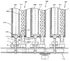
以下、本発明を適用した画像形成装置として、電子写真方式のプリンタ100の一実施形態について説明する。まず、本実施形態に係るプリンタ100の基本的な構成について説明する。図1は、本実施形態に係るプリンタ100の概略構成図である。プリンタ100は、ブラック、シアン、マゼンタ、イエロー(以下、K、C、M、Yと記す)のトナー像を形成するための四つのプロセスユニット26K,26C,26M,26Yを備えている。これらは、画像形成物質として、互いに異なる色のK,C,M,Yトナーを用いるが、それ以外は同様の構成になっており、寿命到達時に交換される。   An embodiment of an electrophotographic printer 100 as an image forming apparatus to which the present invention is applied will be described below. First, the basic configuration of the printer 100 according to this embodiment will be described. FIG. 1 is a schematic configuration diagram of a printer 100 according to the present embodiment. The printer 100 includes four process units 26K, 26C, 26M and 26Y for forming black, cyan, magenta and yellow (hereinafter referred to as K, C, M and Y) toner images. These use K, C, M, and Y toners of different colors as image forming substances, but have the same configuration except that they are replaced at the end of their life.

図2は、四つのプロセスユニット26K,26C,26M,26Yのうちの一つの拡大説明図である。四つのプロセスユニット26K,26C,26M,26Yは使用するトナーの色が異なる点以外は同様であるため、図2では使用するトナーの色を示す添え字(K,C,M,Y)は省略している。図2に示すように、プロセスユニット26は、潜像担持体としてのドラム状の感光体ドラム24、感光体クリーニング装置83、除電装置及び帯電装置25を保持する感光体ユニット30と、現像装置23とを備えている。画像形成ユニットとしてのプロセスユニット26は、プリンタ100本体に脱着可能であり、一度に消耗部品を交換できるようになっている。   FIG. 2 is an enlarged explanatory view of one of the four process units 26K, 26C, 26M and 26Y. The four process units 26K, 26C, 26M, and 26Y are the same except that the colors of the toners used are different, so the subscripts (K, C, M, Y) indicating the colors of the toners used are omitted in FIG. is doing. As shown in FIG. 2, the process unit 26 includes a photosensitive drum unit 30 that holds a drum-shaped photosensitive drum 24 as a latent image carrier, a photosensitive member cleaning device 83, a charge eliminating device and a charging device 25, and a developing device 23. It has and. The process unit 26 as an image forming unit can be attached to and detached from the main body of the printer 100, and consumable parts can be replaced at once.

帯電装置25は、駆動手段によって図中時計回りに回転駆動される感光体ドラム24の表面を一様帯電する。一様帯電された感光体ドラム24の表面は、光書込ユニット27が照射するレーザー光Lによって露光走査されて各色用の静電潜像を担持する。この静電潜像は、トナーを用いる現像装置23によってトナー像に現像される。そして、中間転写ベルト22上に一次転写される。   The charging device 25 uniformly charges the surface of the photoconductor drum 24, which is driven to rotate clockwise in the drawing by the driving unit. The uniformly charged surface of the photosensitive drum 24 is exposed and scanned by the laser light L emitted by the optical writing unit 27, and carries an electrostatic latent image for each color. This electrostatic latent image is developed into a toner image by the developing device 23 that uses toner. Then, the image is primarily transferred onto the intermediate transfer belt 22.

感光体クリーニング装置83は、一次転写工程を経た後の感光体ドラム24の表面に付着している転写残トナーを除去する。また、除電装置は、クリーニング後の感光体ドラム24の残留電荷を除電する。この除電により、感光体ドラム24の表面が初期化されて次の画像形成に備えられる。   The photoconductor cleaning device 83 removes the transfer residual toner adhering to the surface of the photoconductor drum 24 after the primary transfer process. Further, the charge removing device removes the residual charge on the photosensitive drum 24 after cleaning. By this charge removal, the surface of the photoconductor drum 24 is initialized and prepared for the next image formation.

現像装置23は、現像剤としてのトナーを収容する縦長のホッパ部86と、現像部87とを有している。現像剤収容部としてのホッパ部86内には、駆動手段によって回転駆動されるアジテータ88、これの鉛直方向下方で駆動手段によって回転駆動される現像剤供給部材としてのトナー供給ローラ80などが配設されている。ホッパ部86内のトナーは、アジテータ88の回転駆動によって撹拌されながら、自重によってトナー供給ローラ80に向けて移動する。トナー供給ローラ80は、金属製の芯金と、これの表面に被覆された発泡樹脂等からなるローラ部とを有しており、ホッパ部86内下側に溜まったトナーをローラ部の表面に付着させながら回転する。   The developing device 23 has a vertically long hopper portion 86 that stores toner as a developer, and a developing portion 87. Inside the hopper portion 86 as a developer accommodating portion, an agitator 88 rotatably driven by a driving means, a toner supply roller 80 as a developer supplying member rotatably driven by the driving means vertically below the agitator 88, and the like are provided. Has been done. The toner in the hopper unit 86 moves toward the toner supply roller 80 by its own weight while being stirred by the rotational drive of the agitator 88. The toner supply roller 80 has a metal cored bar and a roller part made of foamed resin or the like coated on the surface of the metal cored bar. The toner accumulated on the lower side inside the hopper 86 is transferred to the surface of the roller part. Rotate while attaching.

現像装置23の現像部87内には、感光体ドラム24やトナー供給ローラ80に当接しながら回転する現像ローラ81や、これの表面に先端を当接させる薄層化ブレード82などが配設されている。ホッパ部86内のトナー供給ローラ80に付着したトナーは、現像ローラ81とトナー供給ローラ80との当接部で現像ローラ81の表面に供給される。供給されたトナーは、現像ローラ81の回転に伴って現像ローラ81と薄層化ブレード82との当接位置を通過する際に、現像ローラ81表面上での層厚が規制される。そして、層厚規制後のトナーは、現像ローラ81と感光体ドラム24との当接部である現像領域において、感光体ドラム24表面上の静電潜像に付着する。この付着により、静電潜像がトナー像に現像される。   In the developing unit 87 of the developing device 23, a developing roller 81 that rotates while contacting the photoconductor drum 24 and the toner supply roller 80, a thinning blade 82 that contacts the tip of the developing roller 81, and the like are disposed. ing. The toner attached to the toner supply roller 80 in the hopper unit 86 is supplied to the surface of the developing roller 81 at the contact portion between the developing roller 81 and the toner supply roller 80. When the supplied toner passes the contact position between the developing roller 81 and the thinning blade 82 as the developing roller 81 rotates, the layer thickness on the surface of the developing roller 81 is regulated. Then, the toner after the layer thickness regulation adheres to the electrostatic latent image on the surface of the photoconductor drum 24 in the developing area which is the contact portion between the developing roller 81 and the photoconductor drum 24. Due to this adhesion, the electrostatic latent image is developed into a toner image.

このようなトナー像の形成が、各プロセスユニット26K,26C,26M,26Yで行われ、各色のトナー像が各プロセスユニット26K,26C,26M,26Yのそれぞれの感光体ドラム24上に形成される。   The formation of such a toner image is performed by each process unit 26K, 26C, 26M, 26Y, and the toner image of each color is formed on the photosensitive drum 24 of each process unit 26K, 26C, 26M, 26Y. .

図1に示すように、四つのプロセスユニット26K,26C,26M,26Yの鉛直方向上方には、光書込ユニット27が配設されている。潜像書込装置としての光書込ユニット27は、画像情報に基づいてレーザーダイオードから発したレーザー光Lにより、四つのプロセスユニット26K,26C,26M,26Yにおけるそれぞれの感光体ドラム24を光走査する。この光走査により、感光体ドラム24上に各色用の静電潜像が形成される。かかる構成においては、光書込ユニット27と、四つのプロセスユニット26K,26C,26M,26Yとにより、四つの感光体ドラム24のそれぞれ互いに異なる色の可視像としてのK,C,M,Yトナー像を作像する作像手段として機能している。   As shown in FIG. 1, an optical writing unit 27 is disposed above the four process units 26K, 26C, 26M, and 26Y in the vertical direction. The optical writing unit 27 as a latent image writing device optically scans the respective photosensitive drums 24 in the four process units 26K, 26C, 26M, and 26Y by the laser light L emitted from the laser diode based on the image information. To do. By this optical scanning, an electrostatic latent image for each color is formed on the photosensitive drum 24. In such a configuration, the optical writing unit 27 and the four process units 26K, 26C, 26M, and 26Y make K, C, M, and Y visible images of different colors on the four photoconductor drums 24, respectively. It functions as an image forming means for forming a toner image.

光書込ユニット27は、ポリゴンモータによって回転駆動したポリゴンミラーによって光源から発したレーザー光Lを主走査方向に偏光しながら、複数の光学レンズやミラーを介して感光体ドラム24に照射するものである。光書込ユニット27としては、LEDアレイの複数のLEDから発したLED光によって光書込を行うものを採用してもよい。   The optical writing unit 27 irradiates the photoconductor drum 24 through a plurality of optical lenses and mirrors while polarizing the laser light L emitted from the light source by a polygon mirror rotated by a polygon motor in the main scanning direction. is there. As the optical writing unit 27, a unit that performs optical writing with LED light emitted from a plurality of LEDs of the LED array may be adopted.

四つのプロセスユニット26K,26C,26M,26Yの鉛直方向下方には、無端状の中間転写ベルト22を張架しながら図中反時計回り方向に無端移動させるベルト装置としての転写ユニット75が配設されている。転写ユニット75は、中間転写ベルト22の他に、駆動ローラ76、テンションローラ20、四つの一次転写ローラ74K,74C,74M,74Y、二次転写ローラ21、ベルトクリーニング装置71、クリーニングバックアップローラ72などを備えている。   Below the four process units 26K, 26C, 26M, and 26Y in the vertical direction, a transfer unit 75 is disposed as a belt device for endlessly moving the endless intermediate transfer belt 22 in a counterclockwise direction in the drawing. Has been done. The transfer unit 75 includes a drive roller 76, a tension roller 20, four primary transfer rollers 74K, 74C, 74M and 74Y, a secondary transfer roller 21, a belt cleaning device 71, a cleaning backup roller 72, etc. in addition to the intermediate transfer belt 22. Is equipped with.

ベルト部材であり、転写ベルトである中間転写ベルト22は、そのループ内側に配設された駆動ローラ76、テンションローラ20、クリーニングバックアップローラ72及び四つの一次転写ローラ74K,74C,74M,74Yによって張架されている。そして、駆動手段によって図中反時計回り方向に回転駆動される駆動ローラ76の回転力により、同方向に無端移動される。   The intermediate transfer belt 22, which is a belt member and a transfer belt, is stretched by a driving roller 76, a tension roller 20, a cleaning backup roller 72, and four primary transfer rollers 74K, 74C, 74M, and 74Y arranged inside the loop. It is hung. Then, it is endlessly moved in the same direction by the rotational force of the drive roller 76 which is rotationally driven in the counterclockwise direction in the drawing by the drive means.

四つの一次転写ローラ74K,74C,74M,74Yは、このように無端移動される中間転写ベルト22を感光体ドラム24K,24C,24M,24Yとの間に挟み込んでいる。この挟み込みにより、中間転写ベルト22のおもて面と、感光体ドラム24K,24C,24M,24Yとが当接するK,C,M,Y用の四箇所の一次転写ニップが形成されている。   The four primary transfer rollers 74K, 74C, 74M, and 74Y sandwich the intermediate transfer belt 22 thus endlessly moved between the photoconductor drums 24K, 24C, 24M, and 24Y. Due to this sandwiching, four primary transfer nips for K, C, M, and Y where the front surface of the intermediate transfer belt 22 and the photosensitive drums 24K, 24C, 24M, and 24Y come into contact are formed.

一次転写ローラ74K,74C,74M,74Yには、転写バイアス電源によってそれぞれ一次転写バイアスが印加されている。これにより、感光体ドラム24K,24C,24M,24Yの静電潜像と、一次転写ローラ74K,74C,74M,74Yとの間に転写電界が形成される。なお、一次転写ローラ74に代えて、転写チャージャーや転写ブラシなどを採用してもよい。   A primary transfer bias is applied to each of the primary transfer rollers 74K, 74C, 74M, and 74Y by a transfer bias power source. As a result, a transfer electric field is formed between the electrostatic latent images on the photoconductor drums 24K, 24C, 24M and 24Y and the primary transfer rollers 74K, 74C, 74M and 74Y. Instead of the primary transfer roller 74, a transfer charger or a transfer brush may be adopted.

プロセスユニット26Yの感光体ドラム24Y表面に形成されたY色トナー像は、感光体ドラム24Yの回転に伴って上述のY用の一次転写ニップに進入する。Y用の一次転写ニップでは、転写電界やニップ圧の作用により、Y色トナー像は、感光体ドラム24Y上から中間転写ベルト22上に一次転写される。このようにしてY色トナー像が一次転写された中間転写ベルト22は、その無端移動に伴ってM,C,K用の一次転写ニップを通過する際に、感光体ドラム24M,24C,24K上のM,C,K色トナー像が、Y色トナー像上に順次重ね合わせて一次転写される。この重ね合わせの一次転写により、中間転写ベルト22上には四色トナー像が形成される。   The Y-color toner image formed on the surface of the photoconductor drum 24Y of the process unit 26Y enters the above-described Y primary transfer nip as the photoconductor drum 24Y rotates. In the Y primary transfer nip, the Y color toner image is primarily transferred from the photosensitive drum 24Y onto the intermediate transfer belt 22 by the action of the transfer electric field and the nip pressure. The intermediate transfer belt 22 on which the Y-color toner image is primarily transferred in this manner moves on the photosensitive drums 24M, 24C, and 24K when passing through the primary transfer nips for M, C, and K due to its endless movement. The M, C, and K color toner images are sequentially superposed on the Y color toner image and primarily transferred. By this primary transfer of superposition, a four-color toner image is formed on the intermediate transfer belt 22.

転写ユニット75の二次転写ローラ21は、中間転写ベルト22のループ外側に配設されて、ループ内側のテンションローラ20との間に中間転写ベルト22を挟み込んでいる。この挟み込みにより、中間転写ベルト22のおもて面と、二次転写ローラ21とが当接する二次転写ニップが形成されている。二次転写ローラ21には、転写バイアス電源によって二次転写バイアスが印加される。この印加により、二次転写ローラ21と、アース接続されているテンションローラ20との間には、二次転写電界が形成される。   The secondary transfer roller 21 of the transfer unit 75 is arranged outside the loop of the intermediate transfer belt 22 and sandwiches the intermediate transfer belt 22 with the tension roller 20 inside the loop. Due to this sandwiching, a secondary transfer nip where the front surface of the intermediate transfer belt 22 and the secondary transfer roller 21 are in contact with each other is formed. A secondary transfer bias is applied to the secondary transfer roller 21 by a transfer bias power source. By this application, a secondary transfer electric field is formed between the secondary transfer roller 21 and the tension roller 20 which is grounded.

転写ユニット75の鉛直方向下方には、記録紙を複数枚重ねた紙束の状態で収容している給紙カセット41がプリンタ100の筐体に対してスライド着脱可能に配設されている。この給紙カセット41は、紙束の一番上の記録紙に給紙ローラ42を当接させており、これを所定のタイミングで図中反時計回り方向に回転させることで、その記録紙を給紙路に向けて送り出す。   Below the transfer unit 75 in the vertical direction, a paper feed cassette 41 that accommodates a plurality of recording papers in a bundle of papers is slidably attached to the housing of the printer 100. In this paper feed cassette 41, a paper feed roller 42 is brought into contact with the uppermost recording paper of the paper stack, and the recording paper is rotated by rotating it counterclockwise in the figure at a predetermined timing. Send it toward the paper feed path.

給紙路の末端付近には、二つのレジストローラから構成されるレジストローラ対43が配設されている。このレジストローラ対43は、給紙カセット41から送り出された記録部材としての記録紙をローラ間に挟み込むとすぐに両ローラの回転を停止させる。そして、挟み込んだ記録紙を上述の二次転写ニップ内で中間転写ベルト22上の四色トナー像に同期させ得るタイミングで回転駆動を再開して、記録紙を二次転写ニップに向けて送り出す。   A registration roller pair 43 composed of two registration rollers is disposed near the end of the paper feed path. The registration roller pair 43 stops the rotation of both rollers as soon as the recording paper as a recording member fed from the paper feed cassette 41 is sandwiched between the rollers. Then, the nipped recording paper is restarted to rotate at a timing such that it can be synchronized with the four-color toner image on the intermediate transfer belt 22 in the secondary transfer nip, and the recording paper is sent toward the secondary transfer nip.

二次転写ニップで記録紙に密着された中間転写ベルト22上の四色トナー像は、二次転写電界やニップ圧の影響を受けて記録紙上に一括二次転写され、記録紙の白色と相まって、フルカラートナー像となる。このようにして表面にフルカラートナー像が形成された記録紙は、二次転写ニップを通過すると、二次転写ローラ21や中間転写ベルト22から曲率分離する。そして、転写後搬送路を経由して、定着手段としての定着装置40に送り込まれる。   The four-color toner image on the intermediate transfer belt 22, which is brought into close contact with the recording paper at the secondary transfer nip, is secondarily transferred onto the recording paper collectively under the influence of the secondary transfer electric field and the nip pressure, and combined with the white color of the recording paper. , A full-color toner image. The recording paper on which the full-color toner image is formed on the surface in this way is separated from the secondary transfer roller 21 and the intermediate transfer belt 22 by the curvature when passing through the secondary transfer nip. Then, it is sent to the fixing device 40 as a fixing unit via the post-transfer conveyance path.

定着装置40には、ハロゲンランプ等の発熱源45aを内包する定着ローラ45と、定着ローラ45に所定の圧力で当接しながら回転する加圧ローラ47とが設けられており、定着ローラ45と加圧ローラ47とによって定着ニップを形成している。定着装置40内に送り込まれた記録紙は、その未定着トナー像担持面を定着ローラ45に密着させるようにして、定着ニップに挟まれる。そして、加熱や加圧の影響によってトナー像中のトナーが軟化されて、フルカラー画像が定着される。   The fixing device 40 is provided with a fixing roller 45 including a heat source 45a such as a halogen lamp, and a pressure roller 47 that rotates while contacting the fixing roller 45 with a predetermined pressure. A fixing nip is formed by the pressure roller 47. The recording paper sent into the fixing device 40 is sandwiched in the fixing nip so that its unfixed toner image bearing surface is brought into close contact with the fixing roller 45. Then, the toner in the toner image is softened by the influence of heating and pressurization, and the full-color image is fixed.

片面プリントモードが設定されている場合には、定着装置40内から排出された記録紙は、そのまま機外へと排出される。そして、筐体の上カバー56の上面で構成するスタック部にスタックされる。   When the single-sided print mode is set, the recording paper ejected from inside the fixing device 40 is ejected outside the apparatus as it is. Then, it is stacked on the stack portion formed by the upper surface of the upper cover 56 of the housing.

なお、二次転写ニップを通過した後の中間転写ベルト22には、記録紙に転写されなかった転写残トナーが付着している。これは、中間転写ベルト22のおもて面に当接しているベルトクリーニング装置71によってベルト表面からクリーニングされる。中間転写ベルト22のループ内側に配設されたクリーニングバックアップローラ72は、ベルトクリーニング装置71によるベルトのクリーニングをループ内側からバックアップする。   Incidentally, the transfer residual toner that has not been transferred to the recording paper adheres to the intermediate transfer belt 22 after passing through the secondary transfer nip. This is cleaned from the belt surface by the belt cleaning device 71 which is in contact with the front surface of the intermediate transfer belt 22. The cleaning backup roller 72 arranged inside the loop of the intermediate transfer belt 22 backs up the cleaning of the belt by the belt cleaning device 71 from the inside of the loop.

[実施例1]
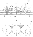
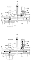
図3は、カラー用感光体ドラム24C,24M,24Yおよびカラー用現像装置23Y,23M,23Cの回転体(現像ローラ81およびトナー供給ローラ80)を駆動する実施例1のカラー用駆動装置とC、M、Y色のプロセスユニット26C,26M,26Yとを示す概略断面図である。
各プロセスユニット側の駆動伝達機構は、同様の構成であるので、ここでは、C色のプロセスユニットについて説明する。
プロセスユニットの装着方向下流側であるプリンタの奥側には、カラー用駆動装置110が配設されている。感光体ドラム24の奥側端部には、回転軸17の先端に取り付けられた駆動側感光体ジョイント112に接続される従動側感光体ジョイント124が設けられている。従動側感光体ジョイント124は、軸受けを介してプロセスユニットのケース126に回転自在に支持されている。
[Example 1]
FIG. 3 illustrates a color driving device C according to the first exemplary embodiment that drives the color photoconductor drums 24C, 24M, 24Y and the rotating bodies (developing roller 81 and toner supply roller 80) of the color developing devices 23Y, 23M, 23C. FIG. 7 is a schematic cross-sectional view showing process units 26C, 26M, and 26Y of M, Y colors.
Since the drive transmission mechanism on the side of each process unit has the same configuration, the process unit of C color will be described here.
A color driving device 110 is arranged on the back side of the printer, which is the downstream side in the mounting direction of the process unit. A driven-side photoconductor joint 124 connected to the drive-side photoconductor joint 112 attached to the tip of the rotary shaft 17 is provided at the rear end of the photoconductor drum 24. The driven-side photoconductor joint 124 is rotatably supported by the case 126 of the process unit via a bearing.

また、現像装置23のトナー供給ローラ80の奥側端部には、従動ギヤ部180bと従動側現像ジョイント部180aとが一体となって構成された従動側現像ギヤ180が設けられている。現像ローラ81の奥側端部には、現像ローラギヤ181が設けられており、現像ローラギヤ181は、現像アイドラギヤ182を介して、従動ギヤ部180bと噛み合っている。従動側現像ジョイント部180aは、駆動側現像ギヤ8の駆動側現像ジョイント部8bに接続されている。   A driven-side developing gear 180 including a driven gear portion 180b and a driven-side developing joint portion 180a formed integrally with each other is provided at the rear end of the toner supply roller 80 of the developing device 23. A developing roller gear 181 is provided at the rear end of the developing roller 81, and the developing roller gear 181 meshes with a driven gear portion 180b via a developing idler gear 182. The driven side developing joint portion 180a is connected to the driving side developing joint portion 8b of the driving side developing gear 8.

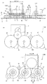
図4(a)は、実施例1のカラー用駆動装置110の概略断面図であり、(b)は、ブラケット9および奥側側板10を取り除いた実施例1のカラー用駆動装置を奥側から見た図である。
図4(a)に示すように、実施例1のカラー用駆動装置110は、カラー用モータ1を備えており、このカラー用モータ1は、ブラケット9のプロセスユニット側の面とは反対側の面に固定されている。カラー用モータ1のモータ軸は、ブラケット9を貫通している。また、モータ軸の外周には歯が形成されておりモータギヤ2となっている。
FIG. 4A is a schematic cross-sectional view of the color driving device 110 of the first embodiment, and FIG. 4B illustrates the color driving device of the first embodiment from which the bracket 9 and the back side plate 10 are removed from the back side. It is the figure seen.
As shown in FIG. 4A, the color driving device 110 of the first embodiment includes the color motor 1, and the color motor 1 is provided on the side opposite to the surface of the bracket 9 on the process unit side. It is fixed to the surface. The motor shaft of the color motor 1 passes through the bracket 9. Further, teeth are formed on the outer periphery of the motor shaft to form the motor gear 2.

ブラケット9と、ブラケット9のプロセスユニット側の面に対向する奥側側板10との間には、Y色の感光体ギヤ3Y、M色の感光体ギヤ3M、C色の感光体ギヤ3Cおよびアイドラギヤ11が配設されている。Y色の感光体ギヤ3YとM色の感光体ギヤ3Mは、カラー用モータ1のモータギヤ2と噛み合っている。アイドラギヤ11は、M色の感光体ギヤ3MとC色の感光体ギヤ3Cとに噛み合っている。   A Y-color photoconductor gear 3Y, an M-color photoconductor gear 3M, a C-color photoconductor gear 3C, and an idler gear are provided between the bracket 9 and the back side plate 10 facing the process unit side surface of the bracket 9. 11 are provided. The Y-color photoconductor gear 3Y and the M-color photoconductor gear 3M mesh with the motor gear 2 of the color motor 1. The idler gear 11 meshes with the M-color photoconductor gear 3M and the C-color photoconductor gear 3C.

各感光体ギヤ3Y,3M,3Cは、ブラケット9と奥側側板10とに回転自在に支持された回転軸17Y,17M,17Cに固定されている。各回転軸17Y,17M,17Cの先端には、駆動側感光体ジョイント112Y,112M,112cが取り付けられている。また、各回転軸17Y,17M,17Cには、電磁クラッチ7Y,7M,7Cおよび、現像出力ギヤ6Y,6M,6Cが設けられている。   The photoconductor gears 3Y, 3M, 3C are fixed to rotating shafts 17Y, 17M, 17C rotatably supported by the bracket 9 and the rear side plate 10. Driving-side photoconductor joints 112Y, 112M, and 112c are attached to the tips of the rotary shafts 17Y, 17M, and 17C. Further, the rotary shafts 17Y, 17M, 17C are provided with electromagnetic clutches 7Y, 7M, 7C and developing output gears 6Y, 6M, 6C.

また、実施例1のカラー用駆動装置110は、駆動側現像ギヤ8Y,8M,8Cを備えており、各駆動側現像ギヤ8Y,8M,8Cは、奥側側板10に設けられた支持軸に回転自在に支持されている。また、各駆動側現像ギヤ8Y,8M,8Cは、現像出力ギヤ6Y,6M,6Cと噛み合う現像ギヤ部8aと駆動側現像ジョイント部8bとが一体で形成されている。   The color drive device 110 of the first embodiment includes drive-side developing gears 8Y, 8M, and 8C, and the drive-side developing gears 8Y, 8M, and 8C are attached to support shafts provided on the back side plate 10. It is rotatably supported. Further, each drive side developing gear 8Y, 8M, 8C is integrally formed with a developing gear portion 8a meshing with the developing output gears 6Y, 6M, 6C and a driving side developing joint portion 8b.

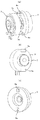
次に、電磁クラッチについて説明する。各色の電磁クラッチは、同様の構成であるので、以下の説明では、色符号を省略して説明する。
図5は、電磁クラッチ7の概略構成図である。また、図6(a)は、電磁クラッチ7と現像出力ギヤ6とを示す斜視図であり、図6(b)は、電磁クラッチ7の斜視図であり、図6(c)は、現像出力ギヤ6の斜視図である。
図5に示すように、駆動伝達切り替え手段たる電磁クラッチ7は、軸固定部7e、電磁コイル部7d、ロータ部7c、アーマチュア7bなどを備えている。軸固定部7eには、回転軸17が挿入される挿入穴を有しており、その挿入穴が、断面D字形状となっている。回転軸17には、このD字形状と嵌合するように、切り欠いて、断面D字部分を有している。軸固定部7eの断面D字形状部分を、回転軸17の断面D字部分と嵌合させることにより、軸固定部7eを、回転軸17と連れ回りするように固定している。
Next, the electromagnetic clutch will be described. Since the electromagnetic clutches of the respective colors have the same configuration, the color code will be omitted in the following description.
FIG. 5 is a schematic configuration diagram of the electromagnetic clutch 7. 6A is a perspective view showing the electromagnetic clutch 7 and the development output gear 6, FIG. 6B is a perspective view of the electromagnetic clutch 7, and FIG. 6C is a development output. It is a perspective view of a gear 6.
As shown in FIG. 5, the electromagnetic clutch 7, which is a drive transmission switching means, includes a shaft fixing portion 7e, an electromagnetic coil portion 7d, a rotor portion 7c, an armature 7b and the like. The shaft fixing portion 7e has an insertion hole into which the rotary shaft 17 is inserted, and the insertion hole has a D-shaped cross section. The rotary shaft 17 has a notch and a D-shaped cross section so as to fit with the D-shape. By fitting the section D-shaped portion of the shaft fixing portion 7e with the section D-shaped portion of the rotating shaft 17, the shaft fixing portion 7e is fixed so as to rotate with the rotating shaft 17.

軸固定部7eには、電磁コイル部7dが、軸固定部7eに対して回転自在に取り付けられている。一方、ロータ部7cは、軸固定部7eと一体で回転するよう軸固定部7eに固定されている。金属円盤からなるアーマチュア7bは、現像出力ギヤ側に延びる一対の駆動爪7aを備えたクラッチ駆動伝達部材7fに取り付けられている。
図5、図6(c)に示すように、現像出力ギヤ6の電磁クラッチ7との対向面には、一対の嵌合穴6aが形成されており、この嵌合穴6aにクラッチ駆動伝達部材7fの駆動爪7aが嵌合している。
An electromagnetic coil portion 7d is rotatably attached to the shaft fixing portion 7e with respect to the shaft fixing portion 7e. On the other hand, the rotor portion 7c is fixed to the shaft fixing portion 7e so as to rotate integrally with the shaft fixing portion 7e. The armature 7b made of a metal disk is attached to a clutch drive transmission member 7f having a pair of drive claws 7a extending toward the developing output gear side.
As shown in FIGS. 5 and 6(c), a pair of fitting holes 6a is formed on the surface of the developing output gear 6 facing the electromagnetic clutch 7, and a clutch drive transmission member is formed in the fitting holes 6a. The drive claw 7a of 7f is fitted.

アーマチュア7bと一体のクラッチ駆動伝達部材7fは、クラッチON時にロータ部7c側へスライド移動してアーマチュア7bがロータ部7cに確実に吸着するように、軸固定部7eに対して、所定のクリアランスを有して軸固定部7eに取り付けられる。そのため、クラッチ駆動伝達部材7fは、どうしても回転軸に対してラジアル方向のガタが大きくなってしまう。その結果、クラッチ駆動伝達部材7fは、自重などにより、回転軸17の軸中心とクラッチ駆動伝達部材7fの回転軸中心とがズレる所謂軸芯ズレが生じる。クラッチがONとなると、この軸芯ズレが生じた状態で、クラッチ駆動伝達部材7fのアーマチュア7bがロータ部7cに密着する。   The clutch drive transmission member 7f, which is integral with the armature 7b, has a predetermined clearance with respect to the shaft fixing portion 7e so that the armature 7b surely attracts to the rotor portion 7c by slidingly moving to the rotor portion 7c side when the clutch is ON. It is attached to the shaft fixing portion 7e. Therefore, the clutch drive transmission member 7f inevitably has a large play in the radial direction with respect to the rotation shaft. As a result, the clutch drive transmission member 7f causes a so-called axial misalignment in which the center of the rotary shaft 17 and the center of the rotary shaft of the clutch drive transmission member 7f are displaced due to their own weight or the like. When the clutch is turned on, the armature 7b of the clutch drive transmission member 7f comes into close contact with the rotor portion 7c in the state where the shaft center deviation occurs.

現像出力ギヤ6にアーマチュア7bを取り付け、現像出力ギヤ6をクラッチ駆動伝達部材7fとした場合は、以下の不具合が生じる。すなわち、クラッチON時にクラッチ駆動伝達部材7fに軸芯ズレがあると、クラッチ駆動伝達部材7fと現像ギヤ部8aとの噛み合い位置がラジアル方向で変動してしまう。その結果、噛み合い位置と回転軸17の中心との距離近くなると、クラッチ駆動伝達部材7fが速く回転し、噛み合い位置が遠くなると、遅く回転することになる。そのため、クラッチ駆動伝達部材7fから駆動力が伝達される現像ギヤ部8aに回転速度ムラが生じ、現像ローラ81Yに回転速度ムラが生じてしまうという不具合である。   When the armature 7b is attached to the development output gear 6 and the development output gear 6 is the clutch drive transmission member 7f, the following problems occur. That is, when the clutch drive transmission member 7f has an axial deviation when the clutch is ON, the meshing position between the clutch drive transmission member 7f and the developing gear portion 8a fluctuates in the radial direction. As a result, the clutch drive transmission member 7f rotates fast when the distance between the meshing position and the center of the rotary shaft 17 becomes short, and slows when the meshing position becomes far. Therefore, the developing gear portion 8a, to which the driving force is transmitted from the clutch drive transmitting member 7f, has uneven rotation speed, and the developing roller 81Y has uneven rotation speed.

これに対し、本実施形態では、現像出力ギヤ6を回転軸17に回転自在に取り付け、現像出力ギヤ6にクラッチ駆動伝達部材7fの駆動爪7aが嵌合する嵌合穴6aを設け、現像出力ギヤ6と電磁クラッチ7とを軸方向から駆動連結している。現像出力ギヤ6は、回転軸17に対して回転可能な隙間でよく、回転軸17に対してラジアル方向に精度よく位置決めされ、現像出力ギヤ6の回転軸中心と、回転軸17との軸中心が精度よく一致している。これにより、現像出力ギヤ6と現像ギヤ部8aとの駆動伝達において、現像ギヤ部8aに回転速度ムラが生じるのを抑制することができる。   On the other hand, in the present embodiment, the developing output gear 6 is rotatably attached to the rotating shaft 17, and the developing output gear 6 is provided with a fitting hole 6a into which the driving claw 7a of the clutch drive transmission member 7f fits. The gear 6 and the electromagnetic clutch 7 are drivingly connected in the axial direction. The developing output gear 6 may be a gap rotatable with respect to the rotating shaft 17, is accurately positioned in the radial direction with respect to the rotating shaft 17, and has a center of the rotating shaft of the developing output gear 6 and a center of the rotating shaft 17. Match exactly. As a result, in the drive transmission between the developing output gear 6 and the developing gear portion 8a, it is possible to prevent the developing gear portion 8a from having uneven rotation speed.

また、現像出力ギヤ6を、電磁クラッチ7と同軸上に設けることで、クラッチON時において、クラッチ駆動伝達部材7fが回転軸17に対して軸芯ズレが生じていても、現像出力ギヤ6とクラッチ駆動伝達部材7fとの間で回転速度ムラが生じることがない。これは、クラッチON時において、クラッチ駆動伝達部材7fのアーマチュア7bがロータ部7cに密着しているとき、クラッチ駆動伝達部材7fの駆動爪7aは、回転軸17の軸中心を中心にして公転する。同様に、回転軸17に取り付けられた現像出力ギヤ6の嵌合穴6aも回転軸17の軸中心を中心にして公転する。このように、駆動爪7a、嵌合穴6aともに回転軸17の軸中心を中心にして公転するため、クラッチ駆動伝達部材7fが回転軸17に対して軸芯ズレが生じていても、クラッチ駆動伝達部材7fと現像出力ギヤ6との接続位置がラジアル方向で変動することがない。その結果、現像出力ギヤ6とクラッチ駆動伝達部材7fとの間の駆動伝達において回転速度ムラが生じるのを抑制することができる。   Further, by providing the developing output gear 6 coaxially with the electromagnetic clutch 7, even when the clutch drive transmission member 7f is misaligned with the rotating shaft 17 when the clutch is ON, the developing output gear 6 and Rotational speed unevenness does not occur with the clutch drive transmission member 7f. This is because when the clutch is ON, when the armature 7b of the clutch drive transmission member 7f is in close contact with the rotor portion 7c, the drive pawl 7a of the clutch drive transmission member 7f revolves around the shaft center of the rotary shaft 17. .. Similarly, the fitting hole 6 a of the developing output gear 6 attached to the rotary shaft 17 also revolves around the shaft center of the rotary shaft 17. In this way, since the drive pawl 7a and the fitting hole 6a revolve around the shaft center of the rotary shaft 17, even if the clutch drive transmission member 7f is displaced from the rotary shaft 17, the clutch drive transmission member 7f is driven. The connection position between the transmission member 7f and the development output gear 6 does not fluctuate in the radial direction. As a result, it is possible to suppress uneven rotation speed in drive transmission between the development output gear 6 and the clutch drive transmission member 7f.

図7は、Y色の感光体ドラムへの駆動伝達経路と、Y色の現像装置の回転体(現像ローラおよびトナー供給ローラ)への駆動経路とについて説明する図である。
図7(a)は、電磁クラッチOFFのときの駆動伝達経路であり、図7(b)は、電磁クラッチONのときの駆動伝達経路である。
図7(a)、図7(b)に示すように、モータギヤ2から回転軸までは、第1駆動伝達経路である感光体ドラム24への駆動伝達経路と、現像装置の回転体への駆動伝達経路とは、共通の駆動伝達経路である。そして、回転軸17で、感光体ドラムへ駆動力を伝達する駆動伝達経路と、現像装置の回転体へ駆動力を伝達する駆動伝達経路とに分かれる。
FIG. 7 is a diagram illustrating a drive transmission path to the Y-color photosensitive drum and a drive path to the rotating body (developing roller and toner supply roller) of the Y-color developing device.
7A shows a drive transmission path when the electromagnetic clutch is OFF, and FIG. 7B shows a drive transmission path when the electromagnetic clutch is ON.
As shown in FIGS. 7A and 7B, from the motor gear 2 to the rotation shaft, the drive transmission path to the photosensitive drum 24, which is the first drive transmission path, and the drive to the rotating body of the developing device. The transmission path is a common drive transmission path. The rotary shaft 17 is divided into a drive transmission path for transmitting the drive force to the photosensitive drum and a drive transmission path for transmitting the drive force to the rotary body of the developing device.

カラー用モータ1が回転駆動すると、その駆動力が、モータギヤ2を介して、Y色の感光体ギヤ3Yに伝達され、Y色の感光体ギヤ3Yが回転駆動する。感光体ギヤ3Yが回転駆動すると、感光体ギヤ3Yが固定された回転軸17Yと、回転軸17Yの先端に固定された駆動側感光体ジョイント112Yが回転駆動する。そして、先の図3に示したように、この駆動側感光体ジョイント112Yに接続された従動側感光体ジョイントに駆動力が伝達され、感光体ドラム24Yが回転駆動する。   When the color motor 1 is rotationally driven, the driving force is transmitted to the Y-color photoconductor gear 3Y via the motor gear 2, and the Y-color photoconductor gear 3Y is rotationally driven. When the photoconductor gear 3Y is rotationally driven, the rotary shaft 17Y to which the photoconductor gear 3Y is fixed and the drive side photoconductor joint 112Y fixed to the tip of the rotary shaft 17Y are rotationally driven. Then, as shown in FIG. 3, the driving force is transmitted to the driven-side photoconductor joint connected to the drive-side photoconductor joint 112Y, and the photoconductor drum 24Y is rotationally driven.

図7(a)に示すように、電磁クラッチ7YがOFFのときは、現像出力ギヤ6に対して回転軸17Yが空回りし、回転軸17Yから現像出力ギヤ6へ駆動力が伝達されない。一方、図7(b)に示すように、電磁クラッチがONのときは、駆動伝達経路が回転軸17で分岐し、電磁クラッチ7を介して現像出力ギヤ6Yに駆動力が伝達され、現像出力ギヤ6Yが回転軸17Yとともに回転駆動する。そして、現像出力ギヤ6Yを介して駆動力が現像ギヤ部8aに伝達され、駆動側現像ギヤ8Yが回転駆動する。そして、先の図3に示したように、駆動側現像ギヤ8Yの駆動側現像ジョイント部8bに接続された従動側現像ジョイント部180aに駆動力が伝達され、トナー供給ローラ80が回転駆動する。また、従動ギヤ部180b、現像アイドラギヤ182、現像ローラギヤ181を経て現像ローラ81Yにカラー用モータの駆動力が伝達され、現像ローラ81Yが回転駆動する。   As shown in FIG. 7A, when the electromagnetic clutch 7Y is OFF, the rotation shaft 17Y idles with respect to the development output gear 6, and the driving force is not transmitted from the rotation shaft 17Y to the development output gear 6. On the other hand, as shown in FIG. 7B, when the electromagnetic clutch is ON, the drive transmission path is branched by the rotary shaft 17, and the driving force is transmitted to the developing output gear 6Y via the electromagnetic clutch 7 to develop the developing output. The gear 6Y is rotationally driven together with the rotary shaft 17Y. Then, the driving force is transmitted to the developing gear portion 8a via the developing output gear 6Y, and the driving side developing gear 8Y is rotationally driven. Then, as shown in FIG. 3, the driving force is transmitted to the driven side developing joint portion 180a connected to the driving side developing joint portion 8b of the driving side developing gear 8Y, and the toner supply roller 80 is rotationally driven. Further, the driving force of the color motor is transmitted to the developing roller 81Y via the driven gear portion 180b, the developing idler gear 182, and the developing roller gear 181, and the developing roller 81Y is rotationally driven.

M色は、同様に、モータギヤ2から感光体ギヤ3Mへ駆動力が伝達される。その後は、上述と同様にして、駆動力が伝達され、感光体ドラム24Mや現像装置23Mの回転体が回転駆動する。C色の感光体ドラム24Cへは、モータギヤ2、M色の感光体ギヤ3M、アイドラギヤ11、C色の感光体ギヤ3Cおよび駆動側感光体ジョイント112cを経てカラー用モータの駆動力が伝達される。その後は、図7とY色と同様にして、駆動伝達が行われる。   Similarly, for the M color, the driving force is transmitted from the motor gear 2 to the photoconductor gear 3M. After that, the driving force is transmitted in the same manner as described above, and the rotating body of the photoconductor drum 24M and the developing device 23M is rotationally driven. The driving force of the color motor is transmitted to the C-color photoconductor drum 24C via the motor gear 2, the M-color photoconductor gear 3M, the idler gear 11, the C-color photoconductor gear 3C, and the driving-side photoconductor joint 112c. .. After that, drive transmission is performed in the same manner as in FIG. 7 and Y color.

本実施例では、カラー用モータ1により、カラー用感光体ドラム24Y,24M,24Cと、カラー用現像装置23Y,23M,23Cの回転体(トナー供給ローラ及び現像ローラ)とを駆動する。よって、カラーの感光体ドラム24Y,24M,24Cを駆動する駆動モータと、カラー用現像装置23Y,23M,23Cの回転体を駆動する駆動モータとを別々に設けるものに比べて、部品点数を削減できる。これにより、装置のコストダウンを図ることができる。また、装置の小型化を図ることができる。   In this embodiment, the color motor 1 drives the color photoconductor drums 24Y, 24M and 24C and the rotating bodies (toner supply roller and developing roller) of the color developing devices 23Y, 23M and 23C. Therefore, the number of parts is reduced as compared with the case where the drive motor for driving the color photoconductor drums 24Y, 24M, 24C and the drive motor for driving the rotating bodies of the color developing devices 23Y, 23M, 23C are separately provided. it can. As a result, the cost of the device can be reduced. Further, the size of the device can be reduced.

また、近年、プリンタの静音性がこれまで以上に強く求められるようになった。本実施形態のように、ひとつのモータで、カラー用感光体ドラム24Y,24M,24Cと、カラー用現像装置23Y,23M,23Cの回転体とを駆動するので、モータ音、モータギヤの噛み合い音などを削減することができる。これにより、装置の静音化を図ることができる。   Further, in recent years, quietness of printers has been required more strongly than ever. As in the present embodiment, one motor drives the color photoconductor drums 24Y, 24M, 24C and the rotating bodies of the color developing devices 23Y, 23M, 23C, so that motor noise, motor gear meshing noise, etc. Can be reduced. This makes it possible to reduce the noise of the device.

また、現像装置内には、現像ローラなど、感光体ドラムよりも寿命が短い部品が搭載されている。本実施例においては、現像装置の回転体(トナー供給ローラ及び現像ローラ)を駆動するための駆動経路に電磁クラッチ7Y,7M,7Cを配置している。これにより、感光体ドラムは、回転駆動する必要がある状態でも、電磁クラッチ7Y,7M,7CをOFFにして、カラー用現像装置23Y,23M,23Cの駆動を停止することができる。これにより、現像装置が早期に寿命を迎えるのを抑制することができる。   Further, in the developing device, components such as a developing roller having a shorter life than the photosensitive drum are mounted. In this embodiment, the electromagnetic clutches 7Y, 7M and 7C are arranged in the drive path for driving the rotating body (toner supply roller and developing roller) of the developing device. As a result, even when the photosensitive drum needs to be rotationally driven, the electromagnetic clutches 7Y, 7M, 7C can be turned off to stop the driving of the color developing devices 23Y, 23M, 23C. As a result, it is possible to prevent the developing device from reaching its end of life at an early stage.

例えば、モータギヤ2で、Y,M,C色の用感光体ドラムに駆動伝達する経路と、Y,M,C色の現像装置に駆動伝達する経路に分かれるように構成した場合以下の不具合ある。すなわち、モータギヤ2から遠く離れたC色の現像装置に駆動伝達するためには、多くのギヤを設ける必要がある。その結果、部品点数の増加による装置のコストアップや、装置の大型化につながるおそれがあるという不具合である。また、ギヤの噛み合い騒音が増大してしまう。これに対し、本実施形態では、電磁クラッチ7を、感光体ギヤが固定された回転軸に取り付け、感光体ギヤに伝達された駆動力を、現像装置に伝達するようにした。これにより、途中まで感光体への駆動伝達経路と、現像装置への駆動伝達経路とを共通化することができ、ギヤの数を減らして、感光体ドラムと、現像装置とにカラー用モータの駆動力を伝達することができる。   For example, if the motor gear 2 is divided into a path for transmitting drive to the Y, M, and C color photosensitive drums and a path for transmitting drive to the Y, M, and C color developing devices, the following problems occur. That is, in order to transmit the drive force to the C-color developing device far away from the motor gear 2, it is necessary to provide many gears. As a result, the cost of the device may increase due to an increase in the number of parts, and the size of the device may increase. In addition, gear meshing noise increases. On the other hand, in this embodiment, the electromagnetic clutch 7 is attached to the rotary shaft to which the photoconductor gear is fixed, and the driving force transmitted to the photoconductor gear is transmitted to the developing device. As a result, the drive transmission path to the photoconductor and the drive transmission path to the developing device can be made common to the middle, the number of gears can be reduced, and the photoconductor drum and the developing device can be provided with a color motor. The driving force can be transmitted.

また、本実施例では、感光体ギヤが固定された回転軸に電磁クラッチを設けることで、現像出力ギヤと噛み合う現像ギヤと、現像駆動側ジョイントとが一体の駆動側現像ギヤ8Y,8M,8Cを用いることができる。これにより、部品点数を削減できる。また、奥側側板10にカシメ固定された支持軸に駆動側現像ギヤ8Y,8M,8Cを回転自在となるように、挿入するだけで、組み付けることができ、組み付け性を高めることができる。   Further, in this embodiment, by providing the electromagnetic clutch on the rotary shaft to which the photoconductor gear is fixed, the developing gear meshing with the developing output gear and the developing drive joint are integrated into the driving side developing gears 8Y, 8M and 8C. Can be used. As a result, the number of parts can be reduced. Further, the drive-side developing gears 8Y, 8M, and 8C can be assembled by simply inserting the drive-side developing gears 8Y, 8M, and 8C so as to be rotatable on the support shaft that is fixed to the rear side plate 10 by caulking, and the assembling property can be improved.

次に、実施例1の変形例について説明する。   Next, a modification of the first embodiment will be described.

[変形例1]
図8は、実施例1の第一変形例である変形例1のカラー用駆動装置110Aの概略構成図であり、(a)は、概略断面図であり、(b)は、奥側側板10およびブラケット9を取り除いた変形例1のカラー用駆動装置110Aを奥側から見た図である。
図8に示すように、この変形例1では、カラー用モータ1を、奥側側板10のプロセスユニットと対向する面に取り付けたものである。
カラー用モータ1を、奥側側板10のプロセスユニットと対向する面に取り付けることで、先の図4に示した構成に比べて、カラー用駆動装置の軸方向長さを短くすることができ、プリンタを軸方向において、小型化を図ることができる。また、カラー用モータ1を装置の内部側に配置することができるので、カラー用モータ1から発生する音を、奥側側板10やブラケット9などにより遮蔽することができる。これにより、カラー用モータ1から発生する音が、プリンタ外部へ漏れるのを抑制することができ、プリンタの静音化を図ることができる。
[Modification 1]
8A and 8B are schematic configuration diagrams of a color driving device 110A of Modification 1 that is a first modification of Embodiment 1, where FIG. 8A is a schematic cross-sectional view, and FIG. 8B is a rear side plate 10. FIG. 11 is a view of a color driving device 110A according to Modification 1 from which the bracket 9 is removed as viewed from the back side.
As shown in FIG. 8, in the first modification, the color motor 1 is attached to the surface of the back side plate 10 facing the process unit.
By mounting the color motor 1 on the surface of the back side plate 10 facing the process unit, the axial length of the color driving device can be shortened as compared with the configuration shown in FIG. It is possible to reduce the size of the printer in the axial direction. Further, since the color motor 1 can be arranged inside the device, the sound generated from the color motor 1 can be shielded by the back side plate 10 or the bracket 9. As a result, the sound generated from the color motor 1 can be suppressed from leaking to the outside of the printer, and the noise of the printer can be reduced.

[変形例2]
図9は、実施例1の第二変形例である変形例2のカラー用駆動装置110Bの斜視図であり、図10は、変形例2のカラー用駆動装置110Bの概略構成図である。図10(a)が、変形例2のカラー用駆動装置110Bの概略断面図であり、図10(b)は、奥側側板10およびブラケット9を取り除いた変形例2のカラー用駆動装置110Bを奥側見た図である。また、図10(c)は、奥側側板10およびブラケット9を取り除いた変形例2のカラー用駆動装置110Bを手前側見た図である。
[Modification 2]
FIG. 9 is a perspective view of a color driving device 110B of Modification 2 which is a second modification of Embodiment 1, and FIG. 10 is a schematic configuration diagram of the color driving device 110B of Modification 2. FIG. 10A is a schematic cross-sectional view of a color driving device 110B of Modification 2, and FIG. 10B shows a color driving device 110B of Modification 2 in which the back side plate 10 and the bracket 9 are removed. It is the figure which looked at the back side. In addition, FIG. 10C is a front view of the color driving device 110</b>B of the second modification in which the back side plate 10 and the bracket 9 are removed.

この変形例2カラー用駆動装置110Bは、プリンタの小型化のため、各色の感光体ドラム24の軸(回転軸17)の軸間距離(stピッチ)を小さくしたものである。Stピッチを小さくした結果、カラー用モータ1のモータ基板1aや、取り付け部材1bの幅が、上記Stピッチよりも大きくなる。その結果、変形例1のように、カラー用モータを装置内部に配置し、モータギヤ2を直接感光体ギヤに噛み合せる構成を採用しようとすると、モータ基板1aや取り付け部材1bが回転軸17に干渉してしまう。   In the second modification color driving device 110B, the inter-axis distance (st pitch) between the shafts (rotary shafts 17) of the photoconductor drums 24 of the respective colors is made small in order to downsize the printer. As a result of reducing the St pitch, the width of the motor substrate 1a of the color motor 1 and the mounting member 1b becomes larger than the St pitch. As a result, when the color motor is arranged inside the apparatus and the motor gear 2 is directly meshed with the photoconductor gear as in the modified example 1, the motor substrate 1a and the mounting member 1b interfere with the rotary shaft 17. Resulting in.

そこで、この変形例2のカラー用駆動装置110Bにおいては、モータギヤ2と感光体ギヤとの間にモータアイドラギヤ13を設けたものである。モータアイドラギヤ13は、C色の感光体ギヤ3CとM色の感光体ギヤ3Mとに噛み合っている。カラー用モータのモータギヤ2は、このモータアイドラギヤ13の頂部(最も高いところ)で噛み合っている。また、この変形例2では、M色の感光体ギヤ3MとY色の感光体ギヤ3Yとの間にアイドラギヤ11が設けられている。実施形態や変形例1と同様に、M色の感光体ギヤ3MとC色の感光体ギヤ3Cとの間にアイドラギヤ11を設けて、モータアイドラギヤ13を、M色の感光体ギヤ3MとY色の感光体ギヤ3Yとの間に設けてもよい。   Therefore, in the color driving device 110B of the second modification, the motor idler gear 13 is provided between the motor gear 2 and the photoconductor gear. The motor idler gear 13 meshes with the C-color photoconductor gear 3C and the M-color photoconductor gear 3M. The motor gear 2 of the color motor meshes with the top (highest point) of the motor idler gear 13. In the second modification, the idler gear 11 is provided between the M color photoconductor gear 3M and the Y color photoconductor gear 3Y. Similar to the embodiment and the first modification, the idler gear 11 is provided between the M color photoconductor gear 3M and the C color photoconductor gear 3C, and the motor idler gear 13 is set to the M color photoconductor gears 3M and Y. It may be provided between the color photoconductor gear 3Y.

かかる構成においては、カラー用駆動装置が変形例1の構成に比べて、上下方向に大きくなるが、軸方向においては、変形例1と同等に小型化を図ることができる。また、この変形例2のカラー用駆動装置110Bにおいても、カラー用モータ1を内部側に配置するので、モータの音が、装置外へ漏れるのを抑制することができる。   In such a configuration, the color driving device is larger in the up-down direction than the configuration of the first modification, but can be downsized in the axial direction as in the first modification. Further, also in the color driving device 110B of the second modification, since the color motor 1 is arranged on the inner side, it is possible to suppress the sound of the motor from leaking out of the device.

また、初段の噛み合いであるモータギヤ2との噛み合いが騒音の付与率が最も高い。この騒音の付与率が高い初段のモータギヤとの噛み合いを一つにすることで、変形例1や実施形態のように、初段のモータギヤに2個の感光体ギヤが噛み合う構成に比べて、騒音を抑制することができる。   Further, the engagement with the motor gear 2, which is the first-stage engagement, has the highest noise imparting rate. By making the meshing with the first-stage motor gear having a high noise application rate to be one, noise is reduced as compared with the configuration in which the two photoconductor gears are meshed with the first-stage motor gear as in the modified example 1 and the embodiment. Can be suppressed.

[変形例3]
図11は、実施例1の第三変形例である変形例3のカラー用駆動装置110Cの概略構成図である。図11(a)は、変形例3のカラー用駆動装置110Cの概略断面図であり、図11(b)は、奥側側板10、ブラケット9を取り除いた変形例3のカラー用駆動装置110Cを奥側から見た図である。また、図11(c)は、奥側側板10、ブラケット9を取り除いた変形例3のカラー用駆動装置110Cを手前側から見た図である。
[Modification 3]
FIG. 11 is a schematic configuration diagram of a color driving device 110C according to Modification 3 which is a third modification of the first embodiment. FIG. 11A is a schematic cross-sectional view of a color driving device 110C of Modified Example 3, and FIG. 11B shows a color driving device 110C of Modified Example 3 in which the back side plate 10 and the bracket 9 are removed. It is the figure seen from the back side. FIG. 11C is a front view of the color driving device 110C according to Modification 3 in which the rear side plate 10 and the bracket 9 are removed.

この変形例3のカラー用駆動装置110Cは、モータアイドラギヤを、内歯歯車13Aとしたものである。具体的には、この内歯歯車13Aは、奥側が閉じられた筒状形状をしており、その内周面に内歯が形成され、外周に外歯が形成されている。モータギヤ2は、内歯歯車の内歯に噛み合っており、内歯歯車の外歯には、Y色の感光体ギヤ3YとM色の感光体ギヤ3Mとが噛み合っている。   In the color driving device 110C of the third modification, the motor idler gear is the internal gear 13A. Specifically, the internal gear 13</b>A has a tubular shape with its inner side closed, and has internal teeth formed on its inner peripheral surface and external teeth formed on its outer peripheral surface. The motor gear 2 meshes with the internal teeth of the internal gear, and the external teeth of the internal gear are meshed with the Y-color photoconductor gear 3Y and the M-color photoconductor gear 3M.

モータアイドラギヤを、内歯歯車とすることで、モータギヤ2との噛み合い率が向上し、振動や騒音を抑制することができる。また、モータギヤ2との噛み合い部を内歯歯車13Aで覆うことができ、噛み合い騒音を内歯歯車13Aにより遮蔽することができる。また、内歯歯車13Aの奥側は、閉じられているため、噛み合い騒音が、外部へ漏れ出るのを抑制することができる。これにより、変形例2のカラー用駆動装置110Bに比べて、装置の静音化を図ることができる。   When the motor idler gear is an internal gear, the meshing ratio with the motor gear 2 is improved, and vibration and noise can be suppressed. Further, the meshing portion with the motor gear 2 can be covered with the internal gear 13A, and meshing noise can be shielded by the internal gear 13A. Further, since the inner side of the internal gear 13A is closed, it is possible to prevent the meshing noise from leaking to the outside. This makes it possible to reduce the noise of the device as compared with the color driving device 110B of the second modification.

図12は、図11(a)に示す破線部Cの拡大図である。
図12に示すように、内歯歯車13Aの内歯、この内歯と噛み合うモータギヤ2をはす歯としている。また、内歯歯車13Aの外歯と、この外歯に噛み合う感光体ギヤ3Y,3Mもはす歯としている。
モータギヤ2のはす歯は、モータ軸の先端側端部が、モータのロータ側端部よりも通常の回転方向下流側となるように捩れたはす歯である。これにより、通常の回転時において、カラー用モータは、モータが取り付けられた奥側側板10に向うようなスラスト力を受ける。これにより、カラー用モータが奥側側板10に押し付けられ、通常の駆動時において、カラー用モータの姿勢を安定させることができる。これにより、回転ムラを抑制できる。また、カラー用モータの振動の発生を抑制し、モータの騒音を低減することができる。なお、通常の回転時および通常の駆動時とは、画像形成時の回転時であり、駆動時のことである。
FIG. 12 is an enlarged view of the broken line portion C shown in FIG.
As shown in FIG. 12, the internal teeth of the internal gear 13A and the motor gear 2 that meshes with the internal teeth are helical teeth. The external teeth of the internal gear 13A and the photoconductor gears 3Y and 3M meshing with the external teeth are also helical teeth.
The helical teeth of the motor gear 2 are helical teeth that are twisted such that the end portion of the motor shaft on the front end side is on the downstream side in the normal rotation direction with respect to the end portion of the motor on the rotor side. As a result, during normal rotation, the color motor receives a thrust force toward the back side plate 10 to which the motor is attached. As a result, the color motor is pressed against the rear side plate 10, and the posture of the color motor can be stabilized during normal driving. As a result, uneven rotation can be suppressed. Further, it is possible to suppress the vibration of the color motor and reduce the noise of the motor. It should be noted that the normal rotation and the normal driving are the rotation during image formation and the driving.

また、内歯歯車13Aの外歯を、ねじれ方向を内歯のねじれ方向と同方向とはす歯とするのが好ましい。内歯歯車13Aの内歯は、図中矢印X1に示すように、装置の手前側(モータ側)にスラスト力を受ける。一方、内歯歯車の外歯は、装置の奥側にスラスト力を受ける。これにより、スラスト力が相殺され、内歯歯車が、奥側側板10に接触したり、ブラケット9に接触したりするのを抑制することができる。   Further, it is preferable that the external teeth of the internal gear 13</b>A are helical teeth whose twist direction is the same as the twist direction of the internal teeth. The internal teeth of the internal gear 13A receive a thrust force on the front side (motor side) of the device, as indicated by an arrow X1 in the figure. On the other hand, the external teeth of the internal gear receive thrust force on the inner side of the device. As a result, the thrust forces are canceled out, and the internal gear can be prevented from coming into contact with the back side plate 10 or the bracket 9.

また、現像出力ギヤ6Y,6Mを、感光体ギヤ3Y,3Mと、ねじれ方向が同一のはす歯とするのが好ましい。内歯歯車13Aの外歯を、内歯と同方向にねじれたはす歯とすることで、感光体ギヤ3Y、3Mは、図中矢印X2に示すように、装置内部側に働くスラスト力を受ける。現像出力ギヤ6Y,6Mを、感光体ギヤ3Y,3Mと、ねじれ方向が同一のはす歯とすることで、現像出力ギヤ6Y,6Mは、装置の奥側にスラスト力を受ける。これにより、現像装置の回転体へ駆動力を伝達しているときは、スラスト力が相殺され、感光体ギヤ3Y,3Mや、現像出力ギヤ6Y,6Mが、奥側側板10やブラケット9に接触するのを抑制することができる。   Further, it is preferable that the development output gears 6Y and 6M are helical teeth having the same twisting direction as the photoconductor gears 3Y and 3M. By setting the external teeth of the internal gear 13A to be helical teeth that are twisted in the same direction as the internal teeth, the photoconductor gears 3Y and 3M generate thrust force acting on the inner side of the device as indicated by an arrow X2 in the figure. receive. By making the development output gears 6Y and 6M be helical teeth having the same twisting direction as that of the photoconductor gears 3Y and 3M, the development output gears 6Y and 6M receive thrust force on the inner side of the apparatus. As a result, when the driving force is being transmitted to the rotating body of the developing device, the thrust force is canceled out, and the photoconductor gears 3Y and 3M and the developing output gears 6Y and 6M come into contact with the back side plate 10 and the bracket 9. Can be suppressed.

また、現像装置の回転体へ駆動力を伝達していないときは、感光体ギヤ3Y、3Mは、図中矢印X2に示すように、装置内部側に働くスラスト力を受ける。これにより、感光体ギヤ3Y,3Mが、内部側の奥側側板10に接触させることができる。その結果、装置外部側のブラケット9に接触する場合に比べて、噛み合い振動などによる騒音が、外部に漏れだすの抑制することができる。   When the driving force is not transmitted to the rotating body of the developing device, the photoconductor gears 3Y and 3M receive the thrust force acting on the inside of the device, as indicated by the arrow X2 in the figure. As a result, the photoconductor gears 3Y and 3M can be brought into contact with the inner side plate 10 on the inner side. As a result, it is possible to suppress the noise due to the meshing vibration from leaking to the outside, as compared with the case where the bracket 9 on the outside of the apparatus is brought into contact with the bracket 9.

[変形例4]
図13は、実施例1の第四変形例である変形例4のカラー用駆動装置110Dの概略構成図である。図13(a)は、変形例4のカラー用駆動装置110Dの概略断面図であり、図13(b)は、奥側側板10、ブラケット9を取り除いた変形例4のカラー用駆動装置110Dを奥側から見た図である。また、図13(c)は、奥側側板10、ブラケット9を取り除いた変形例3のカラー用駆動装置110Dを手前側から見た図である。
[Modification 4]
FIG. 13 is a schematic configuration diagram of a color driving device 110D of Modification 4 which is the fourth modification of the first embodiment. 13A is a schematic cross-sectional view of a color driving device 110D of Modification 4, and FIG. 13B shows a color driving device 110D of Modification 4 in which the back side plate 10 and the bracket 9 are removed. It is the figure seen from the back side. FIG. 13C is a front view of the color driving device 110D according to Modification 3 in which the back side plate 10 and the bracket 9 are removed.

一般的に、電磁クラッチ7Y,7M,7Cは、ギヤなどに比べて寿命が短く、定期的に交換が必要となってくる。感光体ギヤおよび現像出力ギヤよりも内側に電磁クラッチを配置した場合は、電磁クラッチを交換するとき、感光体ギヤおよび現像出力ギヤを取り外す必要があり、電磁クラッチの交換が煩雑となるという課題がある。   Generally, the electromagnetic clutches 7Y, 7M, and 7C have shorter lives than gears and the like, and require periodic replacement. When the electromagnetic clutch is arranged inside the photoconductor gear and the development output gear, when exchanging the electromagnetic clutch, the photoconductor gear and the development output gear need to be removed, which makes the exchange of the electromagnetic clutch complicated. is there.

そこで、この変形例4のカラー用駆動装置110Dでは、電磁クラッチの交換性を高めるため、電磁クラッチ7Y,7M,7Cを、同軸上に設けられた感光体ギヤ3Y,3M,3Cおよび現像出力ギヤ6Y,6M,6Cよりも外側に設けた。また、ブラケット9に電磁クラッチ7Y,7M,7Cにアクセスするための穴部9aを設け、その穴部9aをキャップ部材15により塞いでいる。   Therefore, in the color driving device 110D of the fourth modification, in order to enhance the exchangeability of the electromagnetic clutch, the electromagnetic clutches 7Y, 7M, 7C are provided coaxially with the photoconductor gears 3Y, 3M, 3C and the developing output gears. It was provided outside of 6Y, 6M, and 6C. Further, the bracket 9 is provided with a hole 9a for accessing the electromagnetic clutches 7Y, 7M, 7C, and the hole 9a is closed by the cap member 15.

この変形例4のカラー用駆動装置110Dにおいては、電磁クラッチを交換する際は、プリンタ奥側の外装カバーを取り外して、ブラケット9を露出させる。次に、キャップ部材15を取り外して、ブラケット9の穴部9aから電磁クラッチを露出させる。そして、電磁クラッチを軸方向に移動させて、穴部9aから電磁クラッチを回転軸から取り外して、新品の電磁クラッチを回転軸に取り付ける。   In the color driving device 110D of Modification 4, when replacing the electromagnetic clutch, the exterior cover on the back side of the printer is removed to expose the bracket 9. Next, the cap member 15 is removed to expose the electromagnetic clutch through the hole 9a of the bracket 9. Then, the electromagnetic clutch is moved in the axial direction, the electromagnetic clutch is removed from the rotary shaft through the hole 9a, and a new electromagnetic clutch is attached to the rotary shaft.

このように、この変形例4のカラー用駆動装置110Dにおいては、ブラケット9に電磁クラッチにアクセスするための穴部9aを設けることで、ブラケット9を取り外すことなく、電磁クラッチを交換することができる。また、感光体ギヤ3Y,3M,3Cおよび現像出力ギヤ6Y,6M,6Cを回転軸から取り外すことなく、電磁クラッチを交換することができる。これにより、電磁クラッチの交換を簡単に行うことができる。   As described above, in the color driving device 110D of Modification 4, the bracket 9 is provided with the hole 9a for accessing the electromagnetic clutch, so that the electromagnetic clutch can be replaced without removing the bracket 9. .. Further, the electromagnetic clutch can be replaced without removing the photoconductor gears 3Y, 3M, 3C and the development output gears 6Y, 6M, 6C from the rotary shaft. This makes it possible to easily replace the electromagnetic clutch.

また、この変形例4では、ブラケット9の奥側側板10との対向面から垂直に延び出した支持軸9bに取り付けられたモータ取り付け面部9cに、カラー用モータを取り付けている。かかる構成とすることでも、カラー用モータ1を現像出力ギヤ6と電磁クラッチ7との上方に配置することができる。これにより、ブラケット9の奥側側板10と対向する面と反対側の面にカラー用モータ1を取り付ける場合に比べて、カラー用駆動装置の軸方向長さを短くできる。その結果、プリンタの小型化を図ることができる。   Further, in this modified example 4, the color motor is attached to the motor attachment surface portion 9c attached to the support shaft 9b extending vertically from the surface of the bracket 9 facing the rear side plate 10. With this structure, the color motor 1 can be arranged above the developing output gear 6 and the electromagnetic clutch 7. As a result, the axial length of the color driving device can be shortened as compared with the case where the color motor 1 is mounted on the surface of the bracket 9 opposite to the surface facing the rear side plate 10. As a result, the size of the printer can be reduced.

図14は、カラー用モータのON/OFFおよび電磁クラッチのON/OFFの一例を示すタイミングチャートである。
実施形態および変形例1〜4の駆動装置においては、感光体ドラムに駆動力の伝達を行う回転軸に電磁クラッチが設けられている。電磁クラッチは、ONからOFFに切り替えるときやOFFからONに切り替えるときに衝撃が発生し、その衝撃が振動となり、回転軸、感光体ジョイントを経由して感光体ドラムに伝播する。そして、感光体ドラムが振動し、ショックジターなどの異常画像が生じるおそれがある。従って、電磁クラッチON/OFFのタイミングは、画像に影響が出ないタイミングで行う必要がある。
FIG. 14 is a timing chart showing an example of ON/OFF of the color motor and ON/OFF of the electromagnetic clutch.
In the drive devices of the embodiment and the modified examples 1 to 4, the electromagnetic clutch is provided on the rotating shaft that transmits the driving force to the photosensitive drum. An impact is generated in the electromagnetic clutch when switching from ON to OFF or when switching from OFF to ON, and the impact becomes vibration and propagates to the photoconductor drum via the rotary shaft and the photoconductor joint. Then, the photosensitive drum may vibrate and an abnormal image such as shock jitter may occur. Therefore, it is necessary to turn on/off the electromagnetic clutch at a timing that does not affect the image.

電磁クラッチのOFFからONへの切り替えの衝撃により、帯電装置により感光体表面への一様帯電に影響が及ぶ場合は、以下のタイミングで電磁クラッチ7をOFFからONに切り替える。すなわち、図14に示すよう、モータの駆動を開始して、感光体ドラムが回転を始めてから、帯電装置25により感光体ドラム表面を一様帯電するまでの間に、電磁クラッチをOFFかONに切り替えるのである。なお、電磁クラッチのOFFからONへの切り替えの衝撃により、感光体表面への一様帯電に影響がない場合は、露光開始タイミングt3と、帯電開始タイミングt2との間で、電磁クラッチをOFFからONに切り替えてもよい。露光工程時において、電磁クラッチのOFFからONへの切り替えの衝撃により感光体ドラムが振動すると、静電潜像に影響を及ぼすので、少なくとも露光開始前に、電磁クラッチのOFFからONへの切り替えを行うのが好ましい。   When the impact of switching the electromagnetic clutch from OFF to ON affects the uniform charging of the surface of the photoconductor by the charging device, the electromagnetic clutch 7 is switched from OFF to ON at the following timing. That is, as shown in FIG. 14, the electromagnetic clutch is turned OFF or ON from the time when the driving of the motor is started and the photosensitive drum starts to rotate until the surface of the photosensitive drum is uniformly charged by the charging device 25. Switch. If the impact of switching the electromagnetic clutch from OFF to ON does not affect the uniform charging of the surface of the photoconductor, the electromagnetic clutch is switched from OFF to OFF between the exposure start timing t3 and the charging start timing t2. You may switch to ON. During the exposure process, when the photosensitive drum vibrates due to the impact of switching the electromagnetic clutch from OFF to ON, it affects the electrostatic latent image. Therefore, switch the electromagnetic clutch from OFF to ON at least before starting the exposure. It is preferable to carry out.

また、図14では、定着工程終了後に、電磁クラッチをONからOFFに切り替えているが、現像工程後の電磁クラッチをONからOFFに切り替えるタイミングは、画像に影響がない範囲で早めることができる。しかし、一次転写工程中に電磁クラッチをONからOFFに切り替えると、感光体ドラムの振動により中間転写ベルトに転写した画像に影響を及ぼす。よって、少なくとも、一次転写工程後に、電磁クラッチをONからOFFに切り替えるのが好ましい。   Further, in FIG. 14, the electromagnetic clutch is switched from ON to OFF after the fixing process is completed, but the timing at which the electromagnetic clutch is switched from ON to OFF after the developing process can be advanced within a range that does not affect the image. However, when the electromagnetic clutch is switched from ON to OFF during the primary transfer process, the vibration of the photosensitive drum affects the image transferred to the intermediate transfer belt. Therefore, it is preferable to switch the electromagnetic clutch from ON to OFF at least after the primary transfer process.

また、例えば、電磁クラッチをONからOFFに切り替えた衝撃が、奥側側板10やブラケット9を介して、他の感光体ドラムに伝播し、他の感光体ドラムの回転速度に影響を与える場合がある。この場合は、Y,M,C色の一次転写工程が終了した後に電磁クラッチをONからOFFに切り替えるのが好ましい。また、電磁クラッチをONからOFFに切り替えたときの衝撃が感光体ドラムを介して、中間転写ベルトに伝播し、中間転写ベルトの速度に影響を与える場合は、二次転写工程後に電磁クラッチをONからOFFに切り替えるのが好ましい。   Further, for example, the impact of switching the electromagnetic clutch from ON to OFF may propagate to another photosensitive drum via the back side plate 10 and the bracket 9 and affect the rotational speed of the other photosensitive drum. is there. In this case, it is preferable to switch the electromagnetic clutch from ON to OFF after the primary transfer process of Y, M and C colors is completed. In addition, when the impact when the electromagnetic clutch is switched from ON to OFF is propagated to the intermediate transfer belt via the photoconductor drum and affects the speed of the intermediate transfer belt, the electromagnetic clutch is turned ON after the secondary transfer process. It is preferable to switch from OFF to OFF.

また、上述では、感光体ギヤが固定された回転軸に電磁クラッチを設けた例について説明したが、第二回転体たる現像ローラ81を備えたユニットである現像装置23に駆動力を出力する第二駆動出力部材たる駆動側現像ジョイントと同軸上に電磁クラッチを設けてもよい。以下、駆動側現像ジョイントと同軸上に電磁クラッチを設けた例を、実施例2として説明する。なお、以下の説明では、実施形態で説明したカラー用駆動装置と同一の構成については、適宜、説明を省略する。   Further, in the above description, the example in which the electromagnetic clutch is provided on the rotary shaft to which the photoconductor gear is fixed has been described. However, the driving force is output to the developing
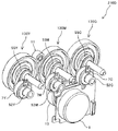
 device 23 that is a unit including the developing roller 81 that is the second rotating body. An electromagnetic clutch may be provided coaxially with the drive side developing joint which is the second drive output member. Hereinafter, an example in which an electromagnetic clutch is provided coaxially with the drive side developing joint will be described as a second embodiment. Note that, in the following description, the description of the same configuration as the color driving device described in the embodiment will be appropriately omitted.

[実施例2]
図15は、実施例2のカラー駆動装置210を示す概略構成図である。
図15に示すように、実施例2のカラー駆動装置210は、Y色の感光体駆動伝達部材130Y、M色の感光体駆動伝達部材130M、C色の感光体駆動伝達部材130Cを有している。各色の感光体駆動伝達部材130Y,130M,130Cは、感光体ギヤ部130aと、現像出力ギヤ部130bと、軸部130cとを有している。軸部130cの先端は、外歯が形成されており、スプライン軸となっている。
[Example 2]
FIG. 15 is a schematic configuration diagram showing the color driving device 210 of the second embodiment.
As shown in FIG. 15, the color driving device 210 of the second embodiment includes a Y-color photoconductor drive transmission member 130Y, an M-color photoconductor drive transmission member 130M, and a C-color photoconductor drive transmission member 130C. There is. The photoconductor drive transmission members 130Y, 130M, and 130C for the respective colors have a photoconductor gear portion 130a, a development output gear portion 130b, and a shaft portion 130c. External teeth are formed at the tip of the shaft portion 130c, which serves as a spline shaft.

各色の感光体ギヤ部130aは、ブラケット9と、ブラケット9のプロセスユニット側の面に対向する奥側側板10との間に配置されている。C色の感光体駆動伝達部材130Cの感光体ギヤ部と、M色の感光体駆動伝達部材130Mの感光体ギヤ部がカラー用モータ1のモータギヤ2と噛み合っている。また、M色の感光体駆動伝達部材130Mの感光体ギヤ部と、Y色の感光体駆動伝達部材130Yの感光体ギヤ部が、アイドラギヤ11と噛み合っている。   The photoconductor gear portion 130a of each color is arranged between the bracket 9 and the back side plate 10 facing the surface of the bracket 9 on the process unit side. The photoconductor gear portion of the C color photoconductor drive transmission member 130C and the photoconductor gear portion of the M color photoconductor drive transmission member 130M mesh with the motor gear 2 of the color motor 1. The photoconductor gear portion of the M color photoconductor drive transmission member 130M and the photoconductor gear portion of the Y color photoconductor drive transmission member 130Y mesh with the idler gear 11.

各色の感光体駆動伝達部材130Y,130M,130Cの現像出力ギヤ部130bには、現像ギヤ51Y,51M,51Cが噛み合っている。各色の現像ギヤ51Y,51M,51Cは、奥側側板10に固定された円筒形状の金属製の軸受部材54Y,54M,54Cの外周面に回転自在に支持されている。また、軸受部材54Y,54M,54Cの内周面には、駆動側現像ジョイント52Y,52M,52Cから延びる現像出力軸53Y,53M,53Cが、回転自在に支持されている。   The developing gears 51Y, 51M and 51C mesh with the developing output gear portions 130b of the photoconductor drive transmitting members 130Y, 130M and 130C of the respective colors. The developing gears 51Y, 51M and 51C of the respective colors are rotatably supported on the outer peripheral surfaces of cylindrical metal bearing members 54Y, 54M and 54C fixed to the back side plate 10. Further, developing output shafts 53Y, 53M, 53C extending from the driving side developing joints 52Y, 52M, 52C are rotatably supported on the inner peripheral surfaces of the bearing members 54Y, 54M, 54C.

電磁クラッチ7Y,7M,7Cは、現像出力軸53Y,53M,53Cに取り付けられており、軸方向から現像ギヤ51Y、51M、51Cと係合している。また、現像出力軸53Y,53M,53Cと一体の第二駆動出力部材としての駆動側現像ジョイント52Y,52M,52Cは、円筒形状をしており、内周面に内歯が形成されている。   The electromagnetic clutches 7Y, 7M, 7C are attached to the developing output shafts 53Y, 53M, 53C and engage with the developing gears 51Y, 51M, 51C from the axial direction. Further, the drive-side developing joints 52Y, 52M, 52C as the second driving output member integrated with the developing output shafts 53Y, 53M, 53C have a cylindrical shape, and inner teeth are formed on the inner peripheral surface thereof.

図16は、実施例2のカラー用駆動装置とC、M、Y色のプロセスユニットとを示す概略断面図である。
各プロセスユニット側の駆動伝達機構は、同様の構成であるので、ここでは、C色のプロセスユニットについて説明するともに、色符号を省略して説明する。
感光体ドラム24の奥側端部には、軸部130cの先端に形成されたスプライン軸が挿入される従動側感光体ジョイント124が設けられている。従動側感光体ジョイント124は、円筒形状であって、内周面に内歯が形成されている。従動側感光体ジョイント124は、軸受けを介してプロセスユニットのケース126に回転自在に支持されている。従動側感光体ジョイント124に軸部130cの先端に形成されたスプライン軸が挿入されることで、スプライン軸の外歯と、従動側感光体ジョイント124の内歯とが噛み合い感光体ドラム24が実施例2のカラー用駆動装置に駆動連結される。
FIG. 16 is a schematic cross-sectional view showing the color driving device and the C, M, and Y color process units of the second embodiment.
Since the drive transmission mechanism on the side of each process unit has the same configuration, the process unit of C color will be described here, and the color code will be omitted.
A driven-side photoconductor joint 124, into which a spline shaft formed at the tip of the shaft portion 130c is inserted, is provided at the rear end of the photoconductor drum 24. The driven-side photoconductor joint 124 has a cylindrical shape and has inner teeth formed on its inner peripheral surface. The driven-side photoconductor joint 124 is rotatably supported by the case 126 of the process unit via a bearing. By inserting the spline shaft formed at the tip of the shaft portion 130c into the driven-side photoconductor joint 124, the outer teeth of the spline shaft and the inner teeth of the driven-side photoconductor joint 124 mesh with each other to form the photoconductor drum 24. It is drivingly connected to the color driving device of Example 2.

また、現像装置23のトナー供給ローラ80の奥側端部には、従動ギヤ部180bと従動側現像ジョイント部180aとが一体となって構成された従動側現像ギヤ180が設けられている。現像ローラ81の奥側端部には、現像ローラギヤ181が設けられており、現像ローラギヤ181は、現像アイドラギヤ182を介して、従動ギヤ部180bと噛み合っている。従動側現像ジョイント部180aは、スプライン軸となっている。駆動側現像ジョイント52に従動側現像ジョイント部180aが挿入されることで、従動側現像ジョイント部180aの外歯と、駆動側現像ジョイント52の内歯とが噛み合い駆動連結される。   A driven-side developing gear 180 including a driven gear portion 180b and a driven-side developing joint portion 180a formed integrally with each other is provided at the rear end of the toner supply roller 80 of the developing device 23. A developing roller gear 181 is provided at the rear end of the developing roller 81, and the developing roller gear 181 meshes with a driven gear portion 180b via a developing idler gear 182. The driven-side developing joint portion 180a serves as a spline shaft. By inserting the driven-side developing joint portion 180a of the driving-side developing joint 52, the outer teeth of the driven-side developing joint portion 180a and the inner teeth of the driving-side developing joint 52 mesh and are drivingly connected.

図17は、実施例2のカラー用駆動装置210において、M色の感光体ドラム24Mへの駆動伝達経路と、M色の現像装置の回転体(現像ローラおよびトナー供給ローラ)への駆動経路とについて説明する図である。
図17(a)は、電磁クラッチOFFのときの駆動伝達経路であり、図17(b)は、電磁クラッチONのときの駆動伝達経路である。
図17(a)、図17(b)に示すように、モータギヤ2から感光体駆動伝達部材130Mの感光体ギヤ部130aまでは、第1駆動伝達経路である感光体ドラム24への駆動伝達経路と、第二駆動伝達経路である現像装置の回転体への駆動伝達経路とは、共通の駆動伝達経路である。そして、感光体駆動伝達部材130Mの現像出力ギヤ部130bにより感光体ドラムへ駆動力を伝達する駆動伝達経路と、現像装置の回転体へ駆動力を伝達する駆動伝達経路とに分かれる。
FIG. 17 shows a drive transmission path to the M-color photosensitive drum 24M and a drive path to the M-color developing device rotating member (developing roller and toner supply roller) in the color driving device 210 of the second embodiment. It is a figure explaining about.
17A shows the drive transmission path when the electromagnetic clutch is OFF, and FIG. 17B shows the drive transmission path when the electromagnetic clutch is ON.
As shown in FIGS. 17A and 17B, from the motor gear 2 to the photoconductor gear portion 130a of the photoconductor drive transmission member 130M, a drive transmission path to the photoconductor drum 24 which is the first drive transmission path. And the drive transmission path to the rotating body of the developing device, which is the second drive transmission path, are common drive transmission paths. The development output gear portion 130b of the photoconductor drive transmission member 130M divides into a drive transmission route that transmits the driving force to the photoconductor drum and a drive transmission route that transmits the driving force to the rotating body of the developing device.

カラー用モータ1が回転駆動すると、その駆動力が、モータギヤ2を介して、感光体駆動伝達部材130Mの感光体ギヤ部130aに伝達され、感光体駆動伝達部材130Mが回転駆動する。感光体駆動伝達部材130が回転駆動すると、感光体駆動伝達部材130Mの軸部130cに接続された従動側感光体ジョイントに駆動力が伝達され、感光体ドラム24Mが回転駆動する。また、感光体駆動伝達部材130Mの現像出力ギヤ部130bと噛み合う現像ギヤ51Mに駆動力が伝達される。   When the color motor 1 is rotationally driven, the driving force is transmitted via the motor gear 2 to the photoconductor gear portion 130a of the photoconductor drive transmission member 130M, and the photoconductor drive transmission member 130M is rotationally driven. When the photoconductor drive transmission member 130 is rotationally driven, the driving force is transmitted to the driven side photoconductor joint connected to the shaft portion 130c of the photoconductor drive transmission member 130M, and the photoconductor drum 24M is rotationally driven. Further, the driving force is transmitted to the developing gear 51M that meshes with the developing output gear portion 130b of the photoconductor drive transmitting member 130M.

図17(a)に示すように、電磁クラッチ7MがOFFのときは、現像出力軸53に対して現像ギヤ51Mが空回りし、現像ギヤ51Mから現像出力軸53Mへ駆動力が伝達されない。その結果、M色の現像装置の回転体(現像ローラおよびトナー供給ローラ)は、回転しない。   As shown in FIG. 17A, when the electromagnetic clutch 7M is OFF, the developing gear 51M idles with respect to the developing output shaft 53, and the driving force is not transmitted from the developing gear 51M to the developing output shaft 53M. As a result, the rotating body (developing roller and toner supply roller) of the M-color developing device does not rotate.

一方、図17(b)に示すように、電磁クラッチ7MがONのときは、現像ギヤ51Mから電磁クラッチ7Mを介して現像出力軸53Mに駆動力が伝達され、現像出力軸53Mが回転駆動する。そして、先の図16に示したように、駆動側現像ジョイント52Mに接続された従動側現像ジョイント部180aに駆動力が伝達され、トナー供給ローラ80が回転駆動する。また、従動ギヤ部180b、現像アイドラギヤ182、現像ローラギヤ181を経て現像ローラ81Yにカラー用モータの駆動力が伝達され、現像ローラ81Yが回転駆動する。   On the other hand, as shown in FIG. 17B, when the electromagnetic clutch 7M is ON, the driving force is transmitted from the developing gear 51M to the developing output shaft 53M via the electromagnetic clutch 7M, and the developing output shaft 53M is rotationally driven. .. Then, as shown in FIG. 16, the driving force is transmitted to the driven side developing joint portion 180a connected to the driving side developing joint 52M, and the toner supply roller 80 is rotationally driven. Further, the driving force of the color motor is transmitted to the developing roller 81Y via the driven gear portion 180b, the developing idler gear 182, and the developing roller gear 181, and the developing roller 81Y is rotationally driven.

C色は、同様に、モータギヤ2から感光体駆動伝達部材130Mの感光体ギヤ部130aに駆動力が伝達される。その後は、上述と同様にして、駆動力が伝達され、感光体ドラム24Cや現像装置23Cの回転体が回転駆動する。Y色の感光体ドラム24Yと、現像装置23Yの各回転体へは、モータギヤ2、M色の感光体駆動伝達部材130M、アイドラギヤ11を経てY色の感光体駆動伝達部材130Yにカラー用モータ1の駆動力が伝達される。その後は、同様にしてY色の感光体ドラム24Yと、Y色の現像装置23Yの各回転体とに駆動伝達が行われる。   Similarly, for the C color, the driving force is transmitted from the motor gear 2 to the photoconductor gear portion 130a of the photoconductor drive transmission member 130M. After that, the driving force is transmitted in the same manner as described above, and the photoconductor drum 24C and the rotating body of the developing device 23C are rotationally driven. To the Y-color photoconductor drum 24Y and each rotating body of the developing device 23Y, the Y-color photoconductor drive transmission member 130Y is transferred to the color motor 1 via the motor gear 2, the M-color photoconductor drive transmission member 130M, and the idler gear 11. Driving force is transmitted. After that, the drive transmission is similarly performed to the Y-color photosensitive drum 24Y and each rotating body of the Y-color developing device 23Y.

本実施例2でも、カラー用モータ1により、カラー用感光体ドラム24Y,24M,24Cと、カラー用現像装置23Y,23M,23Cの回転体(トナー供給ローラ及び現像ローラ)とを駆動する。よって、カラーの感光体ドラム24Y,24M,24Cを駆動する駆動モータと、カラー用現像装置23Y,23M,23Cの回転体を駆動する駆動モータとを別々に設けるものに比べて、部品点数を削減できる。これにより、装置のコストダウンを図ることができる。また、装置の小型化を図ることができる。また、ひとつのモータで、カラー用感光体ドラム24Y,24M,24Cと、カラー用現像装置23Y,23M,23Cの回転体とを駆動するので、モータ音、モータギヤの噛み合い音などを削減することができる。これにより、装置の静音化を図ることができる。   Also in the second embodiment, the color motor 1 drives the color photoconductor drums 24Y, 24M and 24C and the rotating bodies (toner supply roller and developing roller) of the color developing devices 23Y, 23M and 23C. Therefore, the number of parts is reduced as compared with the case where the drive motor for driving the color photoconductor drums 24Y, 24M, 24C and the drive motor for driving the rotating bodies of the color developing devices 23Y, 23M, 23C are separately provided. it can. As a result, the cost of the device can be reduced. Further, the size of the device can be reduced. Further, since one motor drives the color photoconductor drums 24Y, 24M and 24C and the rotating body of the color developing devices 23Y, 23M and 23C, it is possible to reduce motor noise and motor gear meshing noise. it can. This makes it possible to reduce the noise of the device.

本実施例2においても、現像装置の回転体(トナー供給ローラ及び現像ローラ)を駆動するための駆動伝達経路に電磁クラッチ7Y,7M,7Cを配置している。よって、感光体ドラムは、回転駆動する必要がある状態でも、電磁クラッチ7Y,7M,7CをOFFにして、カラー用現像装置23Y,23M,23Cの駆動を停止することができる。これにより、現像装置が早期に寿命を迎えるのを抑制することができる。   Also in the second embodiment, the electromagnetic clutches 7Y, 7M and 7C are arranged in the drive transmission path for driving the rotating body (toner supply roller and developing roller) of the developing device. Therefore, even when the photosensitive drum needs to be rotationally driven, the electromagnetic clutches 7Y, 7M and 7C can be turned off to stop the driving of the color developing devices 23Y, 23M and 23C. As a result, it is possible to prevent the developing device from reaching its end of life at an early stage.

また、この実施例2では、電磁クラッチ7を、現像装置に駆動力を出力する第二駆動出力部材である駆動側現像ジョイント52Mと同軸の現像出力軸53に取り付けている。電磁クラッチ7を、現像出力軸53に取り付けても、実施例1と同様、途中まで感光体への駆動伝達経路と、現像装置への駆動伝達経路とを共通化することができる。これにより、ギヤの数を減らして、感光体ドラムと、現像装置とにカラー用モータの駆動力を伝達することができる。   In the second embodiment, the electromagnetic clutch 7 is attached to the developing output shaft 53 that is coaxial with the driving side developing joint 52M that is the second driving output member that outputs the driving force to the developing device. Even if the electromagnetic clutch 7 is attached to the development output shaft 53, the drive transmission path to the photosensitive member and the drive transmission path to the developing device can be made common to some extent, as in the first embodiment. This makes it possible to reduce the number of gears and transmit the driving force of the color motor to the photosensitive drum and the developing device.

また、本実施例2では、現像出力軸53に電磁クラッチを設けることで、感光体ギヤと、現像出力ギヤと、感光体ドラムへ駆動力を出力する軸とが一体の感光体駆動伝達部材130Y,130M,130Cを用いることができる。これにより、部品点数を削減できる。また、ブラケット9に回転自在に感光体駆動伝達部材130Y,130M,130Cを支持するだけで組み付けることができ、組み付け性を高めることができる。   Further, in the second embodiment, by providing the developing output shaft 53 with the electromagnetic clutch, the photosensitive member drive transmission member 130Y in which the photosensitive member gear, the developing output gear, and the shaft for outputting the driving force to the photosensitive drum are integrated. , 130M, 130C can be used. This can reduce the number of parts. Further, the photosensitive member drive transmission members 130Y, 130M and 130C can be assembled to the bracket 9 only by being rotatably supported, and the assembling property can be improved.

一般的に、感光体ドラムよりも現像装置の回転体(現像ローラや供給ローラ)の方が高速で回転することを求められる。そのため、現像出力ギヤ部130bから現像ギヤ51への駆動伝達において増速させており、感光体駆動伝達部材よりも現像ギヤの方が回転速度が速くなっておりトルクが減少している。電磁クラッチは、先の図5を用いて説明したように、相対的に回転しているアーマチュア7bをロータ部7cに磁力で吸着して、アーマチュア7bとロータ部7cとの間で駆動伝達を行うものである。従って、この吸着時においてトルクに対して電磁力が弱いと、アーマチュア7bがロータ部7cに対して相対的すべり、正しく駆動伝達が行えない。従って、用いる電磁クラッチとしては、電磁クラッチにかかる負荷トルクに応じて電磁力を強くする必要がある。強い電磁力を発生できるものほど、電磁クラッチとして大型化し、また、コストも高くなる。そのため、実施例1のように、感光体ドラム24へ駆動力を出力する軸に電磁クラッチを設けるよりも、現像装置へ駆動力を出力する軸である現像出力軸に電磁クラッチを設けた方が、電磁クラッチに加わる負荷トルクを低減することができる。その結果、感光体ドラム24へ駆動力を出力する軸に電磁クラッチを設けるよりも、小型で安価な電磁クラッチを用いることができる。これにより、装置の小型化を図ることができ、かつ、装置のコストアップを抑制することができる。   Generally, the rotating body (developing roller or supply roller) of the developing device is required to rotate at a higher speed than the photosensitive drum. Therefore, the speed is increased in the drive transmission from the developing output gear unit 130b to the developing gear 51, and the developing gear has a higher rotation speed and the torque is smaller than that of the photoconductor drive transmitting member. As described with reference to FIG. 5 above, the electromagnetic clutch magnetically adsorbs the relatively rotating armature 7b to the rotor portion 7c to perform drive transmission between the armature 7b and the rotor portion 7c. It is a thing. Therefore, when the electromagnetic force is weak with respect to the torque at the time of this attraction, the armature 7b slides relative to the rotor portion 7c, and the drive cannot be transmitted correctly. Therefore, as the electromagnetic clutch used, it is necessary to increase the electromagnetic force according to the load torque applied to the electromagnetic clutch. The one that can generate a stronger electromagnetic force becomes larger in size as an electromagnetic clutch and the cost becomes higher. Therefore, as in the first embodiment, the electromagnetic clutch is provided on the developing output shaft that is the shaft that outputs the driving force to the developing device, rather than the electromagnetic clutch that is provided on the shaft that outputs the driving force to the photosensitive drum 24. The load torque applied to the electromagnetic clutch can be reduced. As a result, it is possible to use an electromagnetic clutch that is smaller and less expensive than an electromagnetic clutch provided on the shaft that outputs the driving force to the photosensitive drum 24. As a result, the size of the device can be reduced, and the cost increase of the device can be suppressed.

現像出力軸53と駆動側現像ジョイント52とは、樹脂の一体成形物であり、現像出力軸53上に設けられた現像ギヤ51も樹脂成形品である。現像ギヤ51を、直接、現像出力軸53に回転自在に支持した場合、樹脂同士の接触となる。樹脂は、金属に比べて表面加工が難しく、樹脂表面の平滑性は、金属に比べて劣る。従って、現像ギヤ51を、直接、現像出力軸53に回転自在に支持した場合、摺動抵抗が、金属の表面に回転支持した場合に比べて高くなってしまう。そこで、この実施例2では、現像ギヤ51を、現像出力軸を受ける金属製の軸受部材54Yの外周面に回転自在に支持した。これにより、現像ギヤ51を、樹脂の現像出力軸53に回転自在に支持する場合に比べて、摺動抵抗が低減され、現像ギヤの摩耗を抑制することができる。また、現像ギヤを回転自在に支持する金属製の部材と、現像出力軸53を受ける軸受部材とをそれぞれ別々に設ける場合に比べて、部品点数を削減することができ、装置を安価にすることができる。   The development output shaft 53 and the drive side development joint 52 are a resin integrally molded product, and the development gear 51 provided on the development output shaft 53 is also a resin molded product. When the developing gear 51 is directly rotatably supported on the developing output shaft 53, the resins contact each other. The surface treatment of resin is more difficult than that of metal, and the smoothness of the resin surface is inferior to that of metal. Therefore, when the developing gear 51 is directly rotatably supported on the developing output shaft 53, the sliding resistance becomes higher than when it is rotatably supported on the surface of the metal. Therefore, in the second embodiment, the developing gear 51 is rotatably supported on the outer peripheral surface of the metal bearing member 54Y that receives the developing output shaft. As a result, sliding resistance is reduced and abrasion of the developing gear can be suppressed as compared with the case where the developing gear 51 is rotatably supported by the resin developing output shaft 53. In addition, the number of parts can be reduced and the cost of the apparatus can be reduced as compared with the case where a metal member that rotatably supports the developing gear and a bearing member that receives the developing output shaft 53 are separately provided. You can

また、この実施例2においては、感光体駆動伝達部材から駆動側現像ジョイント52への駆動伝達が、現像出力ギヤ部130bと現像ギヤ51とのギヤの噛み合いで行われている。これにより、ベルトにより駆動伝達を行う場合に比べて、耐久性を高めることができる。   Further, in the second embodiment, the drive transmission from the photoconductor drive transmission member to the drive side developing joint 52 is performed by the meshing of the gears of the developing output gear portion 130b and the developing gear 51. As a result, durability can be improved as compared with the case where drive transmission is performed by a belt.

次に、この実施例2の変形例について、説明する。   Next, a modified example of the second embodiment will be described.

[変形例A]
図18は、実施例2の第一変形例である変形例Aのカラー用駆動装置210Aの概略構成図である。
この変形例Aのカラー用駆動装置210Aにおいては、感光体駆動伝達部材130Y,130C,130Mから、駆動側現像ジョイント52Y,52M,52C側への駆動伝達を、ベルト伝達としたものである。具体的には、実施例2の感光体駆動伝達部材130Y,130M,130Cの現像出力ギヤ部130bを、現像出力プーリ部130dに変更し、現像ギヤ51Y,51C,51Mを、現像プーリ56Y、56M,56Cに変更している。そして、感光体駆動伝達部材130Y,130M,130Cの現像出力プーリ部130dと、現像プーリ56Y、56M,56Cとにタイミングベルト55Y,55M,55Cを張架している。
[Modification A]
FIG. 18 is a schematic configuration diagram of a color driving device 210A of Modification A that is a first modification of the second embodiment.
In the color driving device 210A of the modified example A, the drive transmission from the photoconductor drive transmission members 130Y, 130C, 130M to the drive side developing joints 52Y, 52M, 52C is belt transmission. Specifically, the development output gear portion 130b of the photoconductor drive transmission members 130Y, 130M, 130C of the second embodiment is changed to the development output pulley portion 130d, and the development gears 51Y, 51C, 51M are replaced with the development pulleys 56Y, 56M. , 56C. Timing belts 55Y, 55M and 55C are stretched around the developing output pulley portion 130d of the photoconductor drive transmission members 130Y, 130M and 130C and the developing pulleys 56Y, 56M and 56C.

電磁クラッチ7Y,7M、7Cは、ONからOFFに切り替えるときやOFFからONに切り替えるときに衝撃が発生し、その衝撃が振動となる。この変形例Aでは、感光体駆動伝達部材130Y,130M,130Cの現像出力プーリ部130dと、現像プーリ56Y、56M,56Cとに張架されたタイミングベルト55Y,55M,55Cが弾性変形して、電磁クラッチのON/OFF切替時に発生する振動を吸収できる。これにより、実施例2と比較して、電磁クラッチのON/OFF切替時の振動の影響で、感光体駆動伝達部材130Y,130M,130Cが振動するのを抑制することができる。その結果、感光体駆動伝達部材130Y,130M,130Cから感光体ドラムに伝播し、感光体ドラムが振動するのを抑制することができ、ショックジターなどの異常画像が生じるのを抑制することができる。   The electromagnetic clutches 7Y, 7M, and 7C generate an impact when switching from ON to OFF or when switching from OFF to ON, and the impact becomes vibration. In this modified example A, the timing belts 55Y, 55M, 55C stretched between the development output pulley section 130d of the photoconductor drive transmission members 130Y, 130M, 130C and the development pulleys 56Y, 56M, 56C are elastically deformed, It is possible to absorb the vibration generated when the electromagnetic clutch is switched ON/OFF. As a result, compared to the second embodiment, it is possible to suppress the vibration of the photoconductor drive transmission members 130Y, 130M, and 130C due to the influence of the vibration when the electromagnetic clutch is switched on/off. As a result, it is possible to prevent the vibrations of the photoconductor drums from propagating from the photoconductor drive transmission members 130Y, 130M, and 130C to vibrate the photoconductor drums, and to suppress the occurrence of abnormal images such as shock jitter. ..

また、現像装置の回転体の回転ムラも上記タイミングベルト55Y,55M,55Cが弾性変形して吸収することができ、現像装置の回転体の回転ムラの影響が、感光体駆動伝達部材130Y,130M,130Cに及ぶのも抑制することができる。   The timing belts 55Y, 55M and 55C can also elastically deform and absorb the uneven rotation of the rotating body of the developing device, and the uneven rotation of the rotating body of the developing device can reduce the influence of the uneven rotation of the developing device. , 130C can be suppressed.

[変形例B]
図19は、実施例2の第二変形例である変形例Bのカラー用駆動装置210Bの概略構成図である。
この変形例Bのカラー用駆動装置210Bは、感光体駆動伝達部材130Y,130M,130Cの現像出力ギヤ部を、内歯130eとしたものである。また、この変形例Bにおいては、駆動側現像ジョイント52Y,52M,52Cを、現像出力軸53Y,53M,53Cと別体とし、現像出力軸53Y,53M,53Cに回転自在に支持している。また、現像ギヤ51Y,51M,51Cを、現像出力軸53Y,53M,53Cと一体で回転するように、現像出力軸53Y,53M,53Cに取り付けている。そして、電磁クラッチ7Y,7M,7Cを、軸方向から駆動側現像ジョイント52Y,52M,52Cに係合させている。
[Modification B]
FIG. 19 is a schematic configuration diagram of a color driving device 210B of Modification B that is the second modification of the second embodiment.
In the color driving device 210B of the modified example B, the development output gear portions of the photoconductor drive transmission members 130Y, 130M and 130C have internal teeth 130e. Further, in this modification B, the drive side development joints 52Y, 52M and 52C are separately provided from the development output shafts 53Y, 53M and 53C and are rotatably supported by the development output shafts 53Y, 53M and 53C. Further, the developing gears 51Y, 51M and 51C are attached to the developing output shafts 53Y, 53M and 53C so as to rotate integrally with the developing output shafts 53Y, 53M and 53C. The electromagnetic clutches 7Y, 7M and 7C are engaged with the drive side developing joints 52Y, 52M and 52C from the axial direction.

この変形例Bでは、感光体駆動伝達部材130Y,130M,130Cの内歯130eから現像ギヤ51Y,51M,51Cへ駆動伝達され、現像出力軸53Y,53M,53Cが回転駆動する。電磁クラッチがOFFのときは、現像出力軸から駆動側現像ジョイントへの駆動伝達が遮断され、現像装置の回転体(現像ローラや供給ローラ)は回転停止状態となっている。電磁クラッチがONのときは、電磁クラッチを介して、現像出力軸から駆動側現像ジョイントへ駆動力が伝達され、現像装置の回転体が回転駆動する。   In this modified example B, the internal teeth 130e of the photoconductor drive transmission members 130Y, 130M and 130C are drive-transmitted to the development gears 51Y, 51M and 51C, and the development output shafts 53Y, 53M and 53C are rotationally driven. When the electromagnetic clutch is OFF, the drive transmission from the developing output shaft to the driving side developing joint is cut off, and the rotating body (developing roller or supply roller) of the developing device is in a stopped state. When the electromagnetic clutch is ON, the driving force is transmitted from the developing output shaft to the driving side developing joint via the electromagnetic clutch, and the rotating body of the developing device is rotationally driven.

この変形例Bにおいては、現像出力ギヤ部を内歯とすることで、現像ギヤ51との噛み合い率が向上し、振動や騒音を抑制することができる。また、現像ギヤ51との噛み合い部を覆うことができ、噛み合い騒音を内歯130eにより遮蔽することができる。また、内歯130eの奥側は、閉じられているため、噛み合い騒音が、外部へ漏れ出るのを抑制することができる。これにより、実施例例2のカラー用駆動装置210Bに比べて、装置の静音化を図ることができる。   In this modified example B, the development output gear portion has internal teeth, whereby the meshing ratio with the development gear 51 is improved, and vibration and noise can be suppressed. Further, the meshing portion with the developing gear 51 can be covered, and the meshing noise can be shielded by the internal teeth 130e. Moreover, since the inner side of the inner teeth 130e is closed, it is possible to prevent the meshing noise from leaking to the outside. As a result, the device can be made quieter than the color driving device 210B of the second embodiment.

また、現像出力ギヤ部を、内歯とすることにより、図19に示すように、感光体ギヤ部130aと、現像出力ギヤ部と、現像ギヤ51とを、軸方向において同じ位置に配置することができる。その結果、先の図15に示した実施例2のカラー用駆動装置に比べて、軸方向に小型化することができる。   Further, by using the internal teeth for the development output gear portion, as shown in FIG. 19, the photoconductor gear portion 130a, the development output gear portion, and the development gear 51 are arranged at the same position in the axial direction. You can As a result, the size can be reduced in the axial direction as compared with the color driving device of the second embodiment shown in FIG.

また、先の図15と図19との比較からわかるように、現像出力ギヤ部が外歯の場合に比べて、現像出力ギヤ部の直径を大きくすることができる。その結果、現像出力ギヤ部の歯数を大きくすることができ、現像ギヤ部と現像ギヤとの噛み合いで、高い増速比を得ることができる。   Further, as can be seen from the comparison between FIG. 15 and FIG. 19, the diameter of the developing output gear portion can be made larger than that in the case where the developing output gear portion has external teeth. As a result, it is possible to increase the number of teeth of the development output gear portion, and it is possible to obtain a high speed increasing ratio by meshing the development gear portion and the development gear.

[変形例C]
図20は、実施例2の第三変形例である変形例Cのカラー用駆動装置210Cの概略構成図である。
この変形例3は、カラー用駆動装置の奥側側板10よりも感光体ドラム側の駆動伝達部材を覆うカバー部材140を設けたものである。カバー部材140で覆うことで、カラー用駆動装置210に異物が混入するのを抑制することができる。カバー部材140は、奥側側板10にネジ141によりネジ止めされている。
[Modification C]
FIG. 20 is a schematic configuration diagram of a color driving device 210C of Modification C that is a third modification of the second embodiment.
The third modification is provided with a cover member 140 that covers the drive transmission member on the photoconductor drum side with respect to the back side plate 10 of the color driving device. By covering with the cover member 140, it is possible to prevent foreign matter from entering the color driving device 210. The cover member 140 is screwed to the back side plate 10 with a screw 141.

また、駆動側現像ジョイント52Y,52M,52Cと一体の現像出力軸53Y,53M,53Cは、軸受部材54Y,54M,54Cの内周に回転自在に支持されているだけである。そのため、駆動側現像ジョイント52Y,52M,52Cや、現像出力軸53Y,53M,53Cに取り付けられた電磁クラッチなどに現像装置の方向に力が加わると、現像出力軸53Y,53M,53Cが軸受部材54Y,54M,54Cから外れてしまうおそれがあった。この変形例Cでは、カバー部材140により、電磁クラッチや駆動側現像ジョイント52Y,52M,52Cが覆われるので、これらに、物などが触れるのを抑制することができる。これにより、現像出力軸53Y,53M,53Cが軸受部材54Y,54M,54から外れるのを抑制することができる。   Further, the development output shafts 53Y, 53M, 53C integrated with the drive side development joints 52Y, 52M, 52C are only rotatably supported on the inner circumferences of the bearing members 54Y, 54M, 54C. Therefore, when a force is applied in the direction of the developing device to the drive-side developing joints 52Y, 52M, 52C and the electromagnetic clutches attached to the developing output shafts 53Y, 53M, 53C, the developing output shafts 53Y, 53M, 53C cause the bearing members to move. There was a risk that it would come off from 54Y, 54M, and 54C. In this modification C, the cover member 140 covers the electromagnetic clutch and the drive-side developing joints 52Y, 52M, and 52C, so that it is possible to prevent objects or the like from touching them. As a result, it is possible to prevent the development output shafts 53Y, 53M, 53C from coming off the bearing members 54Y, 54M, 54.

さらに、この変形例Cにおいては、カバー部材140に突き当たって現像出力軸53Y,53M,53Cが軸受部材54Y,54M,54Cからの抜けるのを防止する抜け止め突起152Y,152M,152Cを、駆動側現像ジョイント52Y,52M,52Cの外周面に設けている。これにより、現像出力軸53Y,53M,53Cが軸受部材54Y,54M,54Cから抜けるのを防止することができる。   Furthermore, in this modification C, the retaining projections 152Y, 152M, 152C for preventing the developing output shafts 53Y, 53M, 53C from coming off the bearing members 54Y, 54M, 54C by hitting the cover member 140 are provided with the drive side. It is provided on the outer peripheral surfaces of the developing joints 52Y, 52M and 52C. This can prevent the development output shafts 53Y, 53M, 53C from coming off from the bearing members 54Y, 54M, 54C.

[変形例D]
図21は、実施例2の第四変形例である変形例Dのカラー用駆動装置210Dの概略斜視図である。
この変形例Dのカラー用駆動装置210Dは、先の図9に示した変形例2のカラー用駆動装置110Bと同様に、モータギヤ2と感光体ギヤ部との間にモータアイドラギヤ13を設けたものである。
[Modification D]
FIG. 21 is a schematic perspective view of a color driving device 210D of Modification D that is a fourth modification of the second embodiment.
In the color driving device 210D of the modified example D, the motor idler gear 13 is provided between the motor gear 2 and the photoconductor gear portion, similarly to the color driving device 110B of the modified example 2 shown in FIG. It is a thing.

この変形例Dにおいても、変形例2と同様に、各色の感光体ドラム24の軸間距離が、カラー用モータ1のモータ基板や、取り付け部材の幅よりも小さくても、カラー用モータ1を、感光体ギヤ部と感光体ドラムとの間に配置することができる。よって、装置の小型化を図ることができる。さらに、初段のモータギヤとの噛み合いを一つにすることができ、初段のモータギヤに2個の感光体ギヤ部が噛み合う構成に比べて、騒音を抑制することができる。   In the modification D as well, as in the modification 2, even if the inter-axial distance of the photosensitive drums 24 of each color is smaller than the width of the motor substrate of the color motor 1 or the mounting member, the color motor 1 is , Can be arranged between the photoconductor gear portion and the photoconductor drum. Therefore, the size of the device can be reduced. Further, the meshing with the first-stage motor gear can be made to be one, and the noise can be suppressed as compared with the configuration in which the two photoconductor gear portions are meshed with the first-stage motor gear.

また、この変形例Dにおいては、モータアイドラギヤ13を、内歯歯車としている。よって、先の図11に示した変形例3と同様に、モータギヤ2との噛み合い率が向上し、振動や騒音を抑制することができる。また、モータギヤ2との噛み合い部を内歯歯車で覆うことができ、噛み合い騒音を内歯歯車により遮蔽することができる。また、内歯歯車の奥側は、閉じられているため、噛み合い騒音が、外部へ漏れ出るのを抑制することができる。これにより、装置の静音化を図ることができる。   Further, in this modification D, the motor idler gear 13 is an internal gear. Therefore, similarly to the modification 3 shown in FIG. 11, the meshing ratio with the motor gear 2 is improved, and vibration and noise can be suppressed. Further, the meshing portion with the motor gear 2 can be covered with the internal gear, and the meshing noise can be shielded by the internal gear. Further, since the inner side of the internal gear is closed, it is possible to prevent the meshing noise from leaking to the outside. This makes it possible to reduce the noise of the device.

[変形例E]
図22は、実施例2の第五変形例である変形例Eのカラー用駆動装置210Eの概略構成図である。
この変形例Eのカラー用駆動装置210Eは、現像ギヤ51Y,51M,51Cに、円筒形状のボス部151Y,151M、151Cを設ける。そして、これらボス部151Y,151M、151Cを、奥側側板10の穴部10aに挿入して、現像ギヤ51Y,51M,51Cを回転自在に奥側側板10に支持している。そして、現像出力軸53Y,53M,53Cは、ボス部151Y,151M、151Cに回転自在に受けられ、奥側側板10に回転自在に支持されている。
[Modification E]
FIG. 22 is a schematic configuration diagram of a color driving device 210E of Modification E that is a fifth modification of the second embodiment.
In the color driving device 210E of the modification E, the developing gears 51Y, 51M, 51C are provided with cylindrical boss portions 151Y, 151M, 151C. The bosses 151Y, 151M, 151C are inserted into the holes 10a of the rear side plate 10 to rotatably support the developing gears 51Y, 51M, 51C on the rear side plate 10. The development output shafts 53Y, 53M, 53C are rotatably received by the boss portions 151Y, 151M, 151C and rotatably supported by the rear side plate 10.

この変形例Eにおいては、軸受部材54Y,54M,54Cを無くすことができ、部品点数の削減を図ることができ、装置のコストダウンを図ることができる。   In this modified example E, the bearing members 54Y, 54M, 54C can be eliminated, the number of parts can be reduced, and the cost of the device can be reduced.

また、K色の感光体ドラム24K、現像装置23Kの回転体(現像ローラ81およびトナー供給ローラ80)を回転駆動する黒用駆動装置の基本構成として、上述した実施例1および変形例1〜4の構成を採用できる。すなわち、駆動モータと、駆動モータのモータギヤに噛み合う感光体ギヤとを有している。また、感光体ギヤが固定された回転軸に、電磁クラッチと、現像出力ギヤと、駆動側感光体ジョイントとが取り付けられている。また、現像出力ギヤに噛み合う現像ギヤ部と駆動側現像ジョイント部とを有する駆動側現像ギヤが、奥側側板10に設けた支持軸に回転自在に支持されている構成である。   In addition, as a basic configuration of the black drive device that rotationally drives the K-color photosensitive drum 24K and the rotating body (developing roller 81 and toner supply roller 80) of the developing device 23K, the above-described first embodiment and the first to fourth modifications. Can be adopted. That is, it has a drive motor and a photoconductor gear that meshes with the motor gear of the drive motor. Further, an electromagnetic clutch, a developing output gear, and a driving side photoconductor joint are attached to a rotating shaft to which the photoconductor gear is fixed. Further, the driving side developing gear having the developing gear portion meshing with the developing output gear and the driving side developing joint portion is rotatably supported by the support shaft provided on the back side plate 10.

また、K色の感光体ドラム24K、現像装置23Kの回転体(現像ローラ81およびトナー供給ローラ80)を回転駆動する黒用駆動装置の基本構成として、上述した実施例2および変形例A〜Eの構成も採用できる。すなわち、駆動モータと、駆動モータのモータギヤと感光体ギヤ部、現像装置の回転体へ駆動力を伝達する現像出力ギヤ部と、感光体ドラムへ駆動力を伝達する軸部とを有する感光体駆動伝達部材とを有する。また、現像装置へ駆動力を出力する駆動側現像ジョイントと同軸上に電磁クラッチと、現像出力ギヤ部と噛み合う現像ギヤとを設ける構成である。   In addition, as a basic configuration of the black driving device that rotationally drives the K-color photosensitive drum 24K and the rotating body (developing roller 81 and toner supply roller 80) of the developing device 23K, the above-described Embodiment 2 and Modifications A to E are used. The configuration of can also be adopted. That is, a photoconductor drive having a drive motor, a motor gear of the drive motor, a photoconductor gear unit, a development output gear unit that transmits the drive force to the rotating body of the developing device, and a shaft unit that transmits the drive force to the photoconductor drum. And a transmission member. Further, an electromagnetic clutch and a developing gear that meshes with the developing output gear portion are provided coaxially with the driving side developing joint that outputs the driving force to the developing device.

以上に説明したものは一例であり、以下の態様毎に特有の効果を奏する。
(態様1)
駆動モータと、前記駆動モータの駆動力を第一回転体に伝達する第一駆動伝達経路と、前記駆動モータの駆動力を伝達する状態と駆動力の伝達を遮断する状態とを切り替え可能な駆動伝達切り替え手段を有し、前記駆動力を第二回転体に伝達する第二駆動伝達経路とを備えた駆動装置において、前記駆動伝達切り替え手段を、前記第一駆動伝達経路に設けられた駆動伝達部材と一体的に回転する回転軸に設けた。
What has been described above is an example, and each of the following aspects has a unique effect.
(Aspect 1)
A drive motor, a first drive transmission path that transmits the drive force of the drive motor to a first rotating body, and a drive that can switch between a state in which the drive force of the drive motor is transmitted and a state in which the transmission of the drive force is cut off. In a drive device having a transmission switching means and a second drive transmission path for transmitting the driving force to a second rotating body, the drive transmission switching means is provided in the first drive transmission path. It is provided on a rotary shaft that rotates integrally with the member.

特許文献1に記載の駆動装置は、第一駆動伝達経路の感光体ギヤなどの駆動伝達部材と、第二駆動伝達経路のクラッチなどの駆動伝達切り替え手段の入力ギヤとを駆動モータのモータギヤにかみ合わせて、モータギヤのところで第一駆動伝達経路と、第二駆動伝達経路とに駆動伝達経路が分かれる。かかる構成においては、現像ローラなどの第二回転体が、感光体ギヤなどの駆動伝達部材と一体的で回転する軸部などの回転軸を挟んでモータギヤとは、反対側に設けられている場合、駆動伝達切り替え手段が、次のように配置される。すなわち、駆動伝達切り替え手段の入力ギヤをモータギヤと噛み合せるため、駆動伝達切り替え手段が、回転軸を挟んで第二回転体とは反対側に配置されることになるのである。その結果、回転軸が邪魔して、駆動伝達切り替え手段の出力ギヤと、現像ギヤなど第二駆動伝達経路の最下流段のギヤとを直接噛み合せることができない。そのため、アイドラギヤを設け、アイドラギヤを介して出力ギヤと、第二駆動伝達経路の最下流段のギヤとの間で駆動伝達を行う構成となってしまう。   In the drive device described in Patent Document 1, a drive transmission member such as a photoconductor gear of a first drive transmission path and an input gear of a drive transmission switching unit such as a clutch of a second drive transmission path are engaged with a motor gear of a drive motor. At the motor gear, the drive transmission path is divided into a first drive transmission path and a second drive transmission path. In such a configuration, in the case where the second rotating body such as the developing roller is provided on the opposite side of the motor gear with the rotating shaft such as the shaft portion that rotates integrally with the drive transmission member such as the photoconductor gear interposed therebetween. The drive transmission switching means is arranged as follows. That is, since the input gear of the drive transmission switching means meshes with the motor gear, the drive transmission switching means is arranged on the opposite side of the second rotary body with the rotary shaft interposed therebetween. As a result, the rotation shaft interferes, and the output gear of the drive transmission switching means and the gear at the most downstream stage of the second drive transmission path such as the developing gear cannot be directly meshed with each other. Therefore, an idler gear is provided, and drive transmission is performed between the output gear and the most downstream gear of the second drive transmission path via the idler gear.

これに対し、態様1では、電磁クラッチなどの駆動伝達切り替え手段を、第一駆動伝達経路に設けられた感光体ギヤなどの駆動伝達部材と一体的に回転する回転軸に設けた。これにより、モータギヤから回転軸までは、第1駆動伝達経路と第二駆動伝達経路は、共通の駆動伝達経路で、回転軸のところで、第1駆動伝達経路と第二駆動伝達経路とが分岐する構成となる。かかる構成とすることで、第二回転体が、駆動モータのモータギヤと回転軸を挟んで反対側に設けられた構成であっても、駆動伝達切り替え手段から、アイドラギヤを介さずに、第二駆動伝達経路の最下流段のギヤ(本実施形態では現像ギヤ部8a)に直接、駆動力を伝達することが可能となる。これにより、特許文献1に記載の駆動装置とは異なり、アイドラギヤが不要となり、部品点数を削減することができ、装置のコストダウンを図ることができる。また、特許文献1に記載の駆動装置に比べて、駆動装置の小型化を図ることが可能となる。   On the other hand, in the aspect 1, the drive transmission switching means such as the electromagnetic clutch is provided on the rotary shaft that rotates integrally with the drive transmission member such as the photoconductor gear provided in the first drive transmission path. As a result, the first drive transmission path and the second drive transmission path are common drive transmission paths from the motor gear to the rotation shaft, and the first drive transmission path and the second drive transmission path branch at the rotation shaft. It will be composed. With such a configuration, even if the second rotating body is provided on the opposite side of the motor gear of the drive motor with the rotating shaft interposed therebetween, the drive transmission switching means does not use the idler gear to drive the second drive member. It becomes possible to directly transmit the driving force to the gear on the most downstream side of the transmission path (the developing gear portion 8a in this embodiment). Thereby, unlike the drive device described in Patent Document 1, an idler gear is not required, the number of parts can be reduced, and the cost of the device can be reduced. Further, it is possible to reduce the size of the drive device as compared with the drive device described in Patent Document 1.

(態様2)
カラー用モータ1などの駆動モータと、前記駆動モータの駆動力を感光体ドラム24などの第一回転体に伝達する第一駆動伝達経路と、前記駆動モータ1の駆動力を伝達する状態と駆動力の伝達を遮断する状態とを切り替え可能な電磁クラッチなどの駆動伝達切り替え手段を有し、前記駆動力を現像ローラなどの第二回転体に伝達する第二駆動伝達経路とを備えた駆動装置において、前記駆動伝達切り替え手段を、前記第二回転体を備える現像装置23などのユニットへ前記駆動力を出力する駆動側現像ジョイント52などの第二駆動出力部材と同軸上に設けた。
(Aspect 2)
A drive motor such as the color motor 1, a first drive transmission path for transmitting the drive force of the drive motor to a first rotating body such as the photosensitive drum 24, a state and drive for transmitting the drive force of the drive motor 1. A drive device having a drive transmission switching means such as an electromagnetic clutch capable of switching between a state in which the transmission of force is cut off, and a second drive transmission path for transmitting the drive force to a second rotating body such as a developing roller. In the above, the drive transmission switching means is provided coaxially with a second drive output member such as a drive side developing joint 52 that outputs the driving force to a unit such as the developing device 23 including the second rotating body.

この態様2においても、態様1と同様、モータギヤから軸部130cなどの回転軸までは、第1駆動伝達経路と第二駆動伝達経路は、共通の駆動伝達経路で、回転軸のところで、第1駆動伝達経路と第二駆動伝達経路とが分岐する構成とできる。かかる構成とすることで、第二回転体が、駆動モータのモータギヤと回転軸を挟んで反対側に設けられた構成であっても、アイドラギヤを介さずに、第二駆動伝達経路の最下流段のギヤ(実施例2では現像ギヤ)に、駆動力を伝達することが可能となる。これにより、特許文献1に記載の駆動装置とは異なり、アイドラギヤが不要となり、部品点数を削減することができ、装置のコストダウンを図ることができる。また、特許文献1に記載の駆動装置に比べて、駆動装置の小型化を図ることが可能となる。   In this aspect 2 as well, as in aspect 1, from the motor gear to the rotary shaft such as the shaft portion 130c, the first drive transmission path and the second drive transmission path are common drive transmission paths, and the first drive transmission path and the second drive transmission path are located at the rotary shaft. The drive transmission path and the second drive transmission path may be branched. With this configuration, even if the second rotating body is provided on the opposite side of the motor gear of the drive motor with the rotation shaft interposed therebetween, the second drive transmission path is most downstream without the idler gear. The driving force can be transmitted to the gear (developing gear in the second embodiment). Thereby, unlike the drive device described in Patent Document 1, the idler gear is not required, the number of parts can be reduced, and the cost of the device can be reduced. Further, it is possible to reduce the size of the driving device as compared with the driving device described in Patent Document 1.

(態様3)
(態様2)において、駆動側現像ジョイント52などの第二駆動出力部材と同軸上に設けられ、感光体駆動伝達部材130などの第一駆動伝達経路を構成する駆動伝達部材を介して駆動力が伝達される現像ギヤ51などの第二駆動伝達部材を、外周面に回転自在に支持し、前記第二駆動出力部材が取り付けられた現像出力軸53などの回転軸を内周面で回転自在に受ける軸受部材54を設けた。
これによれば、実施例2で説明したように、現像ギヤ51などの第二駆動伝達部材を回転自在に支持する部材と、現像出力軸53などの回転軸を内周面で回転自在に受ける部材とをそれぞれ設ける場合に比べて、部品点数を削減することができ、装置のコストダウンを図ることができる。
(Aspect 3)
In (Aspect 2), the driving force is provided via a drive transmission member such as the photoconductor drive transmission member 130 that is provided coaxially with the second drive output member such as the drive side development joint 52 and that constitutes the first drive transmission path. A second drive transmission member such as a developing gear 51 to be transmitted is rotatably supported on the outer peripheral surface, and a rotation shaft such as a development output shaft 53 to which the second drive output member is attached is rotatably supported on the inner peripheral surface. A bearing member 54 for receiving is provided.
According to this, as described in the second embodiment, the member that rotatably supports the second drive transmission member such as the developing gear 51 and the rotating shaft such as the developing output shaft 53 are rotatably received on the inner peripheral surface. The number of parts can be reduced and the cost of the device can be reduced as compared with the case where each member is provided.

(態様4)
(態様1)乃至(態様3)いずれかにおいて、駆動側現像ジョイント52などの第二駆動出力部材と同軸上に設けられた現像ギヤ51などの第二駆動伝達部材は、前記第一駆動伝達経路を構成する感光体駆動伝達部材130などの駆動伝達部材を介して駆動力が伝達される。
これによれば、前記第一駆動伝達経路を構成する感光体駆動伝達部材130などの駆動伝達部材から、第二駆動伝達経路に分岐する。これにより、モータギヤのところで第一駆動伝達経路と、第二駆動伝達経路とに駆動伝達経路が分かれる場合とは異なり、第二回転体が、駆動モータのモータギヤと回転軸を挟んで反対側に設けられた構成であっても、アイドラギヤが不要となり、部品点数を削減することができ、装置のコストダウンを図ることができる。また、特許文献1に記載の駆動装置に比べて、駆動装置の小型化を図ることが可能となる。
(Aspect 4)
In any one of (Aspect 1) to (Aspect 3), the second drive transmission member such as the developing gear 51 provided coaxially with the second drive output member such as the drive side development joint 52 is the first drive transmission path. The driving force is transmitted through a drive transmission member such as the photoconductor drive transmission member 130 that constitutes the.
According to this, the drive transmission member such as the photoconductor drive transmission member 130 forming the first drive transmission path is branched to the second drive transmission path. As a result, unlike the case where the drive transmission path is divided into the first drive transmission path and the second drive transmission path at the motor gear, the second rotating body is provided on the opposite side of the drive motor with the motor gear interposed therebetween. Even with the above configuration, the idler gear is unnecessary, the number of parts can be reduced, and the cost of the device can be reduced. Further, it is possible to reduce the size of the drive device as compared with the drive device described in Patent Document 1.

(態様5)
(態様1)乃至(態様4)いずれかにおいて、第二駆動伝達経路は、ギヤ列を有する。
これによれば、実施例2で説明したように、ベルトにより駆動伝達を行う場合に比べて、耐久性を高めることができる。
(Aspect 5)
In any one of (Aspect 1) to (Aspect 4), the second drive transmission path has a gear train.
According to this, as described in the second embodiment, the durability can be improved as compared with the case where the drive transmission is performed by the belt.

(態様6)
(態様5)において、現像ローラへの駆動伝達経路などの第二駆動伝達経路は、内歯ギヤ有する。
これによれば、変形例Bで説明したように、第二駆動伝達経路を、外歯ギヤのみで構成した場合に比べて、振動や騒音を抑制することができる。また、内歯ギヤとの噛み合い部を内歯ギヤで覆うことができ、噛み合い騒音を内歯ギヤにより遮蔽することができる。これにより、第二駆動伝達経路を、外歯ギヤのみで構成した場合に比べて、装置の静音化を図ることができる。
(Aspect 6)
In (Aspect 5), the second drive transmission path such as the drive transmission path to the developing roller has an internal gear.
According to this, as described in the modification B, it is possible to suppress vibration and noise as compared with the case where the second drive transmission path is configured by only the external gear. Further, the meshing portion with the internal gear can be covered with the internal gear, and meshing noise can be shielded by the internal gear. This makes it possible to reduce the noise of the device as compared with the case where the second drive transmission path is configured only by the external gear.

(態様7)
(態様4)において、前記第二駆動伝達経路は、ベルト駆動伝達部を有する。
これによれば、変形例Aで説明したように、電磁クラッチなどの駆動伝達切り替え手段の駆動伝達切り替え時の振動をベルト駆動伝達部のベルト部材が弾性変形することで、吸収することができる。これにより、駆動伝達切り替え手段の駆動伝達切り替え時の振動の影響が、感光体ドラム24などの第一回転体に及ぶのを抑制することができる。
(Aspect 7)
In (Aspect 4), the second drive transmission path has a belt drive transmission portion.
According to this, as described in the modified example A, the vibration at the time of switching the drive transmission of the drive transmission switching means such as the electromagnetic clutch can be absorbed by elastically deforming the belt member of the belt drive transmission portion. As a result, it is possible to suppress the influence of vibration of the drive transmission switching means during the drive transmission switching from reaching the first rotating body such as the photosensitive drum 24.

(態様8)
(態様1)乃至(態様7)いずれかにおいて、現像ローラ81などの第二回転体は、感光体ドラム24などの第一回転体の回転中に所定のタイミングで停止するものである。
これによれば、電磁クラッチ7などの駆動伝達切り替え手段により駆動力を伝達する状態から駆動力の伝達を遮断する状態へ切り替えることで、現像ローラ81などの二回転体を感光体ドラム24などの第一回転体の回転中に回転を停止することができる。これにより、第二回転体の寿命を延ばすことができる。
(Aspect 8)
In any one of (Aspect 1) to (Aspect 7), the second rotating body such as the developing roller 81 stops at a predetermined timing during the rotation of the first rotating body such as the photosensitive drum 24.
According to this, by switching from the state of transmitting the driving force to the state of interrupting the transmission of the driving force by the driving transmission switching means such as the electromagnetic clutch 7, the two rotating bodies such as the developing roller 81 and the like such as the photosensitive drum 24 are separated. The rotation can be stopped during the rotation of the first rotating body. Thereby, the life of the second rotating body can be extended.

(態様9)
(態様1)乃至(態様8)いずれかにおいて、第一回転体が、感光体ドラム24などの感光体であり、第二回転体が、現像ローラ81である。
実施形態で説明したように現像ローラ81は、感光体ドラム24などの感光体よりも寿命が短いが、感光体の回転中の所定のタイミングで現像ローラの回転を停止することができるので、現像ローラの寿命を延ばすことができる。
(Aspect 9)
In any one of (Aspect 1) to (Aspect 8), the first rotating body is a photosensitive body such as the photosensitive drum 24, and the second rotating body is a developing roller 81.
As described in the embodiment, the developing roller 81 has a shorter life than the photoconductor such as the photoconductor drum 24, but the development roller 81 can stop the rotation of the development roller at a predetermined timing during the rotation of the photoconductor. The life of the roller can be extended.

(態様10)
(態様1)乃至(態様9)いずれかにおいて、カラー用モータ1などの駆動モータのモータ軸に設けられたモータギヤ2の歯を、前記モータ軸の先端側が、前記モータ軸の通常の回転動作時の回転方向において、下流側に位置するように捩れたはす歯とした。
なお、上記「通常の回転動作時」とは、所定期間において、回転時間が長い方の回転方向であり、本実施形態では、画像形成動作が、通常の回転動作時にあたる。
これによれば、変形例3で説明したように、モータギヤ2が、モータ軸の先端側に向うスラスト力を受ける。これにより、モータギヤを有するカラー用モータ1などの駆動モータが、ブラケット9や奥側側板10などの駆動モータが取り付けられるモータ取り付け面に押し付けられる。その結果、駆動時において、駆動モータの姿勢を安定させることができ、回転ムラを抑制することができる。また、駆動モータの振動の発生を抑制し、モータの騒音を低減することができる。
(Aspect 10)
In any one of (Aspect 1) to (Aspect 9), the teeth of the motor gear 2 provided on the motor shaft of the drive motor such as the color motor 1 are arranged such that the tip end side of the motor shaft is in a normal rotational operation The helical tooth was twisted so as to be located on the downstream side in the rotation direction of.
The “normal rotation operation” is the rotation direction in which the rotation time is longer during the predetermined period, and in the present embodiment, the image forming operation corresponds to the normal rotation operation.
According to this, as described in the modification 3, the motor gear 2 receives the thrust force directed toward the tip side of the motor shaft. As a result, the drive motor such as the color motor 1 having the motor gear is pressed against the motor mounting surface on which the drive motor such as the bracket 9 or the rear side plate 10 is mounted. As a result, it is possible to stabilize the posture of the drive motor during driving and suppress uneven rotation. Further, it is possible to suppress the vibration of the drive motor and reduce the noise of the motor.

(態様11)
(態様1)乃至(態様10)いずれかにおいて、カラー用モータ1などの駆動モータのモータギヤ2と噛み合う内歯歯車13Aを備え、感光体ギヤ3などの駆動伝達部材は、内歯歯車13Aの外周面に設けられた外歯部と噛み合うギヤである。
これによれば、変形例3や変形例Dで説明したように、モータギヤ2との噛み合い率が向上し、振動や騒音を抑制することができる。また、モータギヤ2との噛み合い部を内歯歯車13Aで覆うことができ、噛み合い騒音を内歯歯車13Aにより遮蔽することができる。また、外歯歯車に比べて、径方向のサイズを抑えて減速比を稼ぐことができ、外歯歯車に比べて装置の小型化を図ることができる。
(Aspect 11)
In any one of (Aspect 1) to (Aspect 10), an internal gear 13A that meshes with a motor gear 2 of a drive motor such as a color motor 1 is provided, and a drive transmission member such as a photoconductor gear 3 has an outer periphery of the internal gear 13A. It is a gear that meshes with external teeth provided on the surface.
According to this, as described in Modification 3 and Modification D, the engagement rate with the motor gear 2 is improved, and vibration and noise can be suppressed. Further, the meshing portion with the motor gear 2 can be covered with the internal gear 13A, and meshing noise can be shielded by the internal gear 13A. Further, compared with the external gear, the size in the radial direction can be suppressed to increase the reduction ratio, and the device can be downsized as compared with the external gear.

(態様12)
(態様1)乃至(態様11)いずれかにおいて、内歯歯車の内歯部と、前記外歯部とを、ねじれ方向が同一のはす歯とした。
これによれば、変形例3で説明したように、内歯歯車の内歯部が受けるスラスト力の方向と、内歯歯車の外歯部が受けるスラスト力の方向とを互いに逆方向にできる。これにより、内歯歯車の内歯部のスラスト力を外歯部のスラスト力で打ち消すことができ、内歯歯車が、軸方向いずれか一方へ移動するのを抑制することができる。これにより、内歯歯車が、奥側側板10やブラケット9に接触するのを抑制することができる。
(Aspect 12)
In any one of (Aspect 1) to (Aspect 11), the internal tooth portion of the internal gear and the external tooth portion are helical teeth having the same twist direction.
According to this, as described in Modification 3, the direction of the thrust force received by the internal tooth portion of the internal gear and the direction of the thrust force received by the external tooth portion of the internal gear can be made opposite to each other. As a result, the thrust force of the internal gear of the internal gear can be canceled by the thrust of the external gear, and the internal gear can be prevented from moving in either axial direction. This can prevent the internal gear from coming into contact with the back side plate 10 or the bracket 9.

(態様13)
(態様1)乃至(態様12)いずれかにおいて、カラー用モータ1などの駆動モータを、感光体ドラム24などの第一回転体の軸方向において、感光体ギヤ3などの駆動伝達部材と第一回転体との間に配置した。
これによれば、変形例1や変形例Dで説明したように、駆動装置を上記軸方向に小型化することができる。
(Aspect 13)
In any one of (Aspect 1) to (Aspect 12), the drive motor such as the color motor 1 is connected to the drive transmission member such as the photoconductor gear 3 in the axial direction of the first rotating body such as the photoconductor drum 24. It was placed between the rotating body.
According to this, as described in Modification 1 and Modification D, the drive device can be downsized in the axial direction.

(態様14)
(態様1)乃至(態様13)いずれかにおいて、感光体ギヤ3などの駆動伝達部材と、電磁クラッチ7などの駆動伝達切り替え手段から駆動力が伝達される駆動伝達切り替え手段と同軸上に配置された現像出力ギヤ6などの駆動出力部材とが、ねじれ方向が同一方向のはす歯ギヤである。
これによれば、変形例3で説明したように、感光体ギヤ3などの駆動伝達部材が受けるスラスト力の方向と、現像出力ギヤ6などの駆動出力部材が受けるスラスト力の方向とが互いに逆方向となり、スラスト力を打ち消し合うことができる。これにより、電磁クラッチ7などの駆動伝達切り替え手段が駆動モータの駆動力を伝達する状態のときは、回転軸が軸方向いずれか一方へ移動するのを抑制することができる。その結果、電磁クラッチ7などの駆動伝達切り替え手段が駆動モータの駆動力を伝達する状態のときに、この回転軸に固定された感光体ギヤなどが、回転軸とともに移動して、奥側側板10やブラケット9に接触するのを抑制することができる。
(Aspect 14)
In any one of (Aspect 1) to (Aspect 13), the drive transmission member such as the photoconductor gear 3 and the drive transmission switching unit to which the driving force is transmitted from the drive transmission switching unit such as the electromagnetic clutch 7 are arranged coaxially. The drive output member such as the developing output gear 6 is a helical gear having the same twisting direction.
According to this, as described in Modification 3, the direction of the thrust force received by the drive transmission member such as the photoconductor gear 3 and the direction of the thrust force received by the drive output member such as the development output gear 6 are opposite to each other. The thrust forces can be canceled out. Accordingly, when the drive transmission switching means such as the electromagnetic clutch 7 is in the state of transmitting the drive force of the drive motor, it is possible to prevent the rotation shaft from moving in either axial direction. As a result, when the drive transmission switching means such as the electromagnetic clutch 7 transmits the drive force of the drive motor, the photoconductor gear or the like fixed to the rotary shaft moves together with the rotary shaft, and the back side plate 10 is moved. The contact with the bracket 9 can be suppressed.

(態様15)
(態様1)乃至(態様14)いずれかにおいて、感光体ギヤ3などの駆動伝達部材と、電磁クラッチ7などの駆動伝達切り替え手段から駆動力が伝達される駆動伝達切り替え手段と同軸上に配置された現像出力ギヤ6などの駆動出力部材とを、前記駆動伝達切り替え手段よりも感光体ドラム24などの第一回転体側に配置した。
これによれば、変形例4で説明したように、感光体ギヤ3などの駆動伝達部材や現像出力ギヤ6などの駆動出力部材を、回転軸17から取り外すことなく、電磁クラッチ7などの駆動伝達切り替え手段を回転軸17から取り外すことができ、駆動伝達切り替え手段の交換を容易に行うことができる。
(Aspect 15)
In any one of (Aspect 1) to (Aspect 14), the drive transmission member such as the photoconductor gear 3 and the drive transmission switching unit to which the driving force is transmitted from the drive transmission switching unit such as the electromagnetic clutch 7 are arranged coaxially. The drive output member such as the developing output gear 6 is arranged closer to the first rotating body such as the photosensitive drum 24 than the drive transmission switching means.
According to this, as described in the modified example 4, the drive transmission member such as the photoconductor gear 3 and the drive output member such as the development output gear 6 are not removed from the rotary shaft 17, and the drive transmission such as the electromagnetic clutch 7 is performed. The switching means can be removed from the rotary shaft 17, and the drive transmission switching means can be easily replaced.

(態様16)
(態様1)乃至(態様15)いずれかにおいて、駆動伝達切り替え手段が、電磁クラッチである。
これによれば、電磁クラッチをONにすることで、駆動力を伝達する状態にでき、OFFにすることで、駆動力の伝達を遮断する状態にすることができる。
(Aspect 16)
In any one of (Aspect 1) to (Aspect 15), the drive transmission switching means is an electromagnetic clutch.
According to this, when the electromagnetic clutch is turned on, the driving force can be transmitted, and when the electromagnetic clutch is turned off, the driving force can be interrupted.

(態様17)
感光体ドラム24などの感光体と、現像ローラ81を有し、前記感光体の表面に形成された潜像を現像する現像装置23と、前記感光体と前記現像ローラとを駆動する駆動装置とを備えた画像形成装置において、前記駆動装置として(態様1)乃至(態様16)いずれかの駆動装置を備えた。
これによれば、画像形成装置のコストダウンを図ることができ、また、画像形成装置の小型化を図ることが可能となる。
(Aspect 17)
A developing device 23 having a photoconductor such as the photoconductor drum 24 and a developing roller 81, for developing a latent image formed on the surface of the photoconductor, and a driving device for driving the photoconductor and the developing roller. In the image forming apparatus including, the driving device according to any one of (Aspect 1) to (Aspect 16) is provided as the driving device.
According to this, the cost of the image forming apparatus can be reduced, and the size of the image forming apparatus can be reduced.

(態様18)
(態様17)において、感光体ドラム24などの感光体の表面を一様帯電する帯電装置25と、前記感光体の表面に静電潜像を形成する光書込ユニット27などの潜像形成装置と、前記感光体の表面に形成した画像を中間転写ベルト22などの転写体に転写する一次転写ローラ74などの転写装置とを備え、前記第一回転体が前記感光体であり、前記第二回転体が前記現像ローラであって、電磁クラッチなどの駆動伝達切り替え手段は、前記潜像形成装置による潜像形成開始前に、駆動力の伝達を遮断する状態から駆動力を伝達する状態へ切り替え、前記転写装置による画像転写終了後、駆動力を伝達する状態から駆動力の伝達を遮断する状態への切り替える。
これによれば、図14を用いて説明したように、電磁クラッチ7などの駆動伝達切り替え手段により伝達状態を切り替えるときの衝撃の影響によりショックジターなどの異常画像の発生を抑制することができる。
(Aspect 18)
In (Aspect 17), a charging device 25 that uniformly charges the surface of a photoconductor such as the photoconductor drum 24, and a latent image forming device such as an optical writing unit 27 that forms an electrostatic latent image on the surface of the photoconductor. And a transfer device such as a primary transfer roller 74 that transfers the image formed on the surface of the photoconductor to a transfer body such as the intermediate transfer belt 22, and the first rotating body is the photoconductor, The rotating body is the developing roller, and the drive transmission switching means such as an electromagnetic clutch switches from a state in which the transmission of the driving force is interrupted to a state in which the driving force is transmitted before the latent image formation by the latent image forming device is started. After the image transfer by the transfer device is completed, the state of transmitting the driving force is switched to the state of interrupting the transmission of the driving force.
According to this, as described with reference to FIG. 14, it is possible to suppress the generation of an abnormal image such as a shock jitter due to the impact of switching the transmission state by the drive transmission switching unit such as the electromagnetic clutch 7.

1:カラー用モータ(駆動モータ)
1a:モータ基板
1b:取り付け部材
2:モータギヤ
3:感光体ギヤ
6:現像出力ギヤ
7:電磁クラッチ(駆動伝達切り替え手段)
8:駆動側現像ギヤ
8a:現像ギヤ部
8b:駆動側現像ジョイント部
9:ブラケット
9a:穴部
10:奥側側板
11:アイドラギヤ
13:モータアイドラギヤ
13A:内歯歯車
15:キャップ部材
17:回転軸
22:中間転写ベルト(転写体)
23:現像装置
24:感光体ドラム(感光体)
25:帯電装置
26:プロセスユニット
27:光書込ユニット
51:現像ギヤ
52:駆動側現像ジョイント
53:現像出力軸
54:軸受部材
55:タイミングベルト
56:現像プーリ
74:一次転写ローラ(転写装置)
80:トナー供給ローラ
81:現像ローラ
110:カラー用駆動装置
110A:変形例1のカラー用駆動装置
110B:変形例2のカラー用駆動装置
110C:変形例3のカラー用駆動装置
110D:変形例4のカラー用駆動装置
112:駆動側感光体ジョイント
124:従動側感光体ジョイント
130:感光体駆動伝達部材
130a:感光体ギヤ部
130b:現像出力ギヤ部
130c:軸部
130d:現像出力プーリ部
140:カバー部材
151:ボス部
152:抜け止め突起
180:従動側現像ギヤ
180a:従動側現像ジョイント部
180b:従動ギヤ部
181:現像ローラギヤ
1: Color motor (drive motor)
1a: motor board 1b: mounting member 2: motor gear 3: photoconductor gear 6: development output gear 7: electromagnetic clutch (drive transmission switching means)
8: Drive side development gear 8a: Development gear portion 8b: Drive side development joint portion 9: Bracket 9a: Hole portion 10: Back side plate 11: Idler gear 13: Motor idler gear 13A: Internal gear 15: Cap member 17: Rotation Axis 22: Intermediate transfer belt (transfer body)
23: developing device 24: photoconductor drum (photoconductor)
25: Charging device 26: Process unit 27: Optical writing unit 51: Development gear 52: Drive side development joint 53: Development output shaft 54: Bearing member 55: Timing belt 56: Development pulley 74: Primary transfer roller (transfer device)
80: Toner supply roller 81: Developing roller 110: Color drive device 110A: Color drive device 110B of Modification 1; Color drive device 110C of Modification 2; Color drive device 110D of Modification 3; Modification 4 Color driving device 112: drive side photoconductor joint 124: driven side photoconductor joint 130: photoconductor drive transmission member 130a: photoconductor gear portion 130b: development output gear portion 130c: shaft portion 130d: development output pulley portion 140: Cover member 151: Boss portion 152: Retaining protrusion 180: Driven side developing gear 180a: Driven side developing joint portion 180b: Driven gear portion 181: Developing roller gear

特開2012−208458号公報JP2012-208458A

Claims (13)

駆動モータと、
前記駆動モータの駆動力を第一回転体に伝達する第一駆動伝達経路と、
前記駆動モータの駆動力を伝達する状態と駆動力の伝達を遮断する状態とを切り替え可能な駆動伝達切り替え手段を有し、前記駆動力を第二回転体に伝達する第二駆動伝達経路とを備えた駆動装置において、
前記駆動伝達切り替え手段を、前記第一駆動伝達経路を構成する駆動伝達部材と一体的に回転する回転軸に設け、
前記第二駆動伝達経路は、ギヤ列を有し、
前記駆動伝達部材と、前記駆動伝達切り替え手段から駆動力が伝達される駆動伝達切り替え手段と同軸上に配置された駆動出力部材とが、ねじれ方向が同一方向のはす歯ギヤであることを特徴とする駆動装置。
Drive motor,
A first drive transmission path for transmitting the drive force of the drive motor to the first rotating body;
A second drive transmission path for transmitting the drive force to the second rotating body, which has drive transmission switching means capable of switching between a state in which the drive force of the drive motor is transmitted and a state in which the transmission of the drive force is interrupted. In the provided drive device,
The drive transmission switching means, set to a rotating shaft that rotates the drive transmission member and integrally constituting the first drive transmission path,
The second drive transmission path has a gear train,
The drive transmission member and the drive output member arranged coaxially with the drive transmission switching unit to which the driving force is transmitted from the drive transmission switching unit are helical gears having the same twist direction. Drive device.
請求項1に記載の駆動装置において、  The drive device according to claim 1,
前記駆動伝達部材と、前記駆動伝達切り替え手段から駆動力が伝達される駆動伝達切り替え手段と同軸上に配置された駆動出力部材とを、前記駆動伝達切り替え手段よりも第一回転体側に配置したことを特徴とする駆動装置。The drive transmission member and the drive output member coaxially arranged with the drive transmission switching unit to which the driving force is transmitted from the drive transmission switching unit are arranged closer to the first rotating body than the drive transmission switching unit. A drive device characterized by.
駆動モータと、  Drive motor,
前記駆動モータの駆動力を第一回転体に伝達する第一駆動伝達経路と、A first drive transmission path for transmitting the drive force of the drive motor to the first rotating body;
前記駆動モータの駆動力を伝達する状態と駆動力の伝達を遮断する状態とを切り替え可能な駆動伝達切り替え手段を有し、前記駆動力を第二回転体に伝達する第二駆動伝達経路とを備えた駆動装置において、A second drive transmission path for transmitting the drive force to the second rotating body, which has drive transmission switching means capable of switching between a state in which the drive force of the drive motor is transmitted and a state in which the transmission of the drive force is interrupted. In the provided drive device,
前記駆動伝達切り替え手段を、前記第一駆動伝達経路を構成する駆動伝達部材と一体的に回転する回転軸に設け、The drive transmission switching means is provided on a rotary shaft that rotates integrally with a drive transmission member that constitutes the first drive transmission path,
前記第二駆動伝達経路は、ギヤ列を有し、The second drive transmission path has a gear train,
前記駆動伝達部材と、前記駆動伝達切り替え手段から駆動力が伝達される駆動伝達切り替え手段と同軸上に配置された駆動出力部材とを、前記駆動伝達切り替え手段よりも第一回転体側に配置したことを特徴とする駆動装置。The drive transmission member and the drive output member coaxially arranged with the drive transmission switching unit to which the driving force is transmitted from the drive transmission switching unit are arranged closer to the first rotating body than the drive transmission switching unit. A drive device characterized by.
求項1乃至3いずれかに記載の駆動装置において、
前記第二駆動伝達経路は、内歯ギヤを有することを特徴とする駆動装置。
The drive device according to any Motomeko 1 to 3,
The second drive transmission path includes an internal gear, and a drive device.
請求項1乃至いずれかに記載の駆動装置において、
前記第二回転体は、前記第一回転体の回転中に所定のタイミングで停止するものであることを特徴とする駆動装置。
The drive device according to any one of claims 1 to 4 ,
The drive device, wherein the second rotating body is stopped at a predetermined timing while the first rotating body is rotating.
請求項1乃至いずれかに記載の駆動装置において、
前記第一回転体が、感光体であり、前記第二回転体が、現像ローラであることを特徴とする駆動装置。
The drive device according to any one of claims 1 to 5 ,
The driving device, wherein the first rotating body is a photoconductor and the second rotating body is a developing roller.
請求項1乃至いずれかに記載の駆動装置において、
前記駆動モータのモータ軸に設けられたモータギヤの歯を、前記モータ軸の先端側が、前記モータ軸の通常の回転動作時の回転方向において下流側に位置するように捩れたはす歯としたことを特徴とする駆動装置。
The drive device according to any one of claims 1 to 6 ,
The teeth of the motor gear provided on the motor shaft of the drive motor are helical teeth that are twisted so that the tip end side of the motor shaft is located on the downstream side in the rotation direction during normal rotation operation of the motor shaft. A drive device characterized by.
請求項1乃至7いずれかに記載の駆動装置において、
前記駆動モータのモータギヤと噛み合う内歯歯車を備え、
前記第一駆動伝達経路を構成する駆動伝達部材は、前記内歯歯車の外周面に設けられた外歯部と噛み合うギヤであることを特徴とする駆動装置。
The drive device according to one of claims 1 to 7 have shifted,
An internal gear that meshes with the motor gear of the drive motor,
The drive device, wherein the drive transmission member forming the first drive transmission path is a gear that meshes with an external tooth portion provided on an outer peripheral surface of the internal gear.
請求項8に記載の駆動装置において、
前記内歯歯車の内歯部と、前記外歯部とを、ねじれ方向が同一のはす歯としたことを特徴とする駆動装置。
The drive device according to claim 8 ,
A drive device in which the internal tooth portion of the internal gear and the external tooth portion are helical teeth having the same twist direction.
請求項1乃至9いずれかに記載の駆動装置において、
前記駆動モータを、前記第一回転体の軸方向において、前記第一駆動伝達経路を構成する駆動伝達部材と前記第一回転体との間に配置したことを特徴とする駆動装置
The drive device according to one of claims 1 to 9 have shifted,
The drive device is characterized in that the drive motor is arranged between a drive transmission member forming the first drive transmission path and the first rotary body in an axial direction of the first rotary body .
求項1乃至10いずれかに記載の駆動装置において、
前記駆動伝達切り替え手段が、電磁クラッチであることを特徴とする駆動装置。
The drive device according to any Motomeko 1 to 10,
The drive device, wherein the drive transmission switching means is an electromagnetic clutch.
感光体と、
現像ローラを有し、前記感光体の表面に形成された潜像を現像する現像装置と、
前記感光体と前記現像ローラとを駆動する駆動装置とを備えた画像形成装置において、
前記駆動装置として請求項1乃至11いずれかに記載の駆動装置を備えたことを特徴とする画像形成装置。
A photoconductor,
A developing device having a developing roller for developing the latent image formed on the surface of the photoconductor;
In an image forming apparatus including a driving device that drives the photoconductor and the developing roller,
An image forming apparatus comprising the driving device according to any one of claims 1 to 11 as the drive device.
請求項12に記載の画像形成装置において、
前記感光体の表面を一様帯電する帯電装置と、
前記感光体の表面に静電潜像を形成する潜像形成装置と、
前記感光体の表面に形成した画像を転写体に転写する転写装置とを備え、
前記第一回転体が前記感光体であり、前記第二回転体が前記現像ローラであって、
前記駆動伝達切り替え手段は、前記潜像形成装置による潜像形成開始前に、駆動力の伝達を遮断する状態から駆動力を伝達する状態へ切り替え、前記転写装置による画像転写終了後、駆動力を伝達する状態から駆動力の伝達を遮断する状態への切り替えることを特徴とする画像形成装置。
The image forming apparatus according to claim 12 ,
A charging device for uniformly charging the surface of the photoconductor,
A latent image forming device for forming an electrostatic latent image on the surface of the photoreceptor,
A transfer device for transferring the image formed on the surface of the photoreceptor to a transfer body,
The first rotating body is the photoconductor, the second rotating body is the developing roller,
The drive transmission switching unit switches from a state in which the transmission of the driving force is blocked to a state in which the driving force is transmitted before the latent image formation by the latent image forming device is started, and the driving force is changed after the image transfer by the transfer device is completed. An image forming apparatus characterized by switching from a transmission state to a state in which transmission of a driving force is cut off.
JP2016098234A 2015-10-26 2016-05-16 Drive device and image forming apparatus Active JP6697712B2 (en)

Applications Claiming Priority (2)

Application Number Priority Date Filing Date Title
JP2015209872 2015-10-26

Publications (3)

Publication Number Publication Date
JP2017083006A JP2017083006A (en) 2017-05-18
JP2017083006A5 JP2017083006A5 (en) 2019-03-28
JP6697712B2 true JP6697712B2 (en) 2020-05-27

Family

ID=58713057

Family Applications (1)

Application Number Title Priority Date Filing Date
JP2016098234A Active JP6697712B2 (en) 2015-10-26 2016-05-16 Drive device and image forming apparatus

Country Status (1)

Country Link
JP (1) JP6697712B2 (en)

Families Citing this family (2)

* Cited by examiner, † Cited by third party
Publication number Priority date Publication date Assignee Title
JP7035724B2 (en) * 2018-03-30 2022-03-15 ブラザー工業株式会社 Image forming device
US11500321B2 (en) * 2020-05-18 2022-11-15 Brother Kogyo Kabushiki Kaisha Image-forming apparatus including structure for switching transmission state of driving force to photosensitive drum

Also Published As

Publication number Publication date
JP2017083006A (en) 2017-05-18

Similar Documents

Publication Publication Date Title
US8583001B2 (en) Developing device and process cartridge
JP5424115B2 (en) Drive transmission device and image forming apparatus
US7555242B2 (en) Image forming apparatus having drive system according to loads
JP2014034995A (en) Driving transmission device and image formation device
JP7075617B2 (en) Drive transmission device and image forming device
US8903278B2 (en) Drive unit, and image forming apparatus and process cartridge incorporating same
JP6697712B2 (en) Drive device and image forming apparatus
JP2016196898A (en) Driving device and image forming device
JP6052596B2 (en) Image forming apparatus
JP5311215B2 (en) Driving device and image forming apparatus
JP6468490B2 (en) Driving device and image forming apparatus
CN110850693A (en) Drive transmission device and image forming apparatus
JP2006301346A (en) Drive device for rotator and image forming apparatus with same
JP2018155866A (en) Image formation apparatus
JP4963565B2 (en) Image forming apparatus
JP6555576B2 (en) Driving device and image forming apparatus
JP6489438B2 (en) Driving device and image forming apparatus
JP2007072448A (en) Image forming apparatus
JP2017003635A (en) Drive device and image formation apparatus
JP2012233488A (en) Planetary gear shifting mechanism, rotary driving device and image forming apparatus
JP7402424B2 (en) Drive transmission member, drive transmission device, and image forming device
JP2019152890A (en) Drive device and image formation apparatus
JP2011150376A (en) Image forming apparatus
JP6555570B2 (en) Driving device and image forming apparatus
JP4894230B2 (en) Image forming apparatus

Legal Events

Date Code Title Description
A521 Written amendment

Free format text: JAPANESE INTERMEDIATE CODE: A523

Effective date: 20190212

A621 Written request for application examination

Free format text: JAPANESE INTERMEDIATE CODE: A621

Effective date: 20190220

A977 Report on retrieval

Free format text: JAPANESE INTERMEDIATE CODE: A971007

Effective date: 20191212

A131 Notification of reasons for refusal

Free format text: JAPANESE INTERMEDIATE CODE: A131

Effective date: 20191227

A521 Written amendment

Free format text: JAPANESE INTERMEDIATE CODE: A523

Effective date: 20200225

TRDD Decision of grant or rejection written
A01 Written decision to grant a patent or to grant a registration (utility model)

Free format text: JAPANESE INTERMEDIATE CODE: A01

Effective date: 20200327

A61 First payment of annual fees (during grant procedure)

Free format text: JAPANESE INTERMEDIATE CODE: A61

Effective date: 20200409

R151 Written notification of patent or utility model registration

Ref document number: 6697712

Country of ref document: JP

Free format text: JAPANESE INTERMEDIATE CODE: R151