JP6691041B2 - Vial transfer and injection devices and methods - Google Patents
Vial transfer and injection devices and methods Download PDFInfo
- Publication number
- JP6691041B2 JP6691041B2 JP2016521495A JP2016521495A JP6691041B2 JP 6691041 B2 JP6691041 B2 JP 6691041B2 JP 2016521495 A JP2016521495 A JP 2016521495A JP 2016521495 A JP2016521495 A JP 2016521495A JP 6691041 B2 JP6691041 B2 JP 6691041B2
- Authority
- JP
- Japan
- Prior art keywords
- injection device
- vial
- injection
- bladder
- pressure chamber
- Prior art date
- Legal status (The legal status is an assumption and is not a legal conclusion. Google has not performed a legal analysis and makes no representation as to the accuracy of the status listed.)
- Active
Links
Images


Classifications
-
- A—HUMAN NECESSITIES
- A61—MEDICAL OR VETERINARY SCIENCE; HYGIENE
- A61M—DEVICES FOR INTRODUCING MEDIA INTO, OR ONTO, THE BODY; DEVICES FOR TRANSDUCING BODY MEDIA OR FOR TAKING MEDIA FROM THE BODY; DEVICES FOR PRODUCING OR ENDING SLEEP OR STUPOR
- A61M5/00—Devices for bringing media into the body in a subcutaneous, intra-vascular or intramuscular way; Accessories therefor, e.g. filling or cleaning devices, arm-rests
- A61M5/14—Infusion devices, e.g. infusing by gravity; Blood infusion; Accessories therefor
- A61M5/142—Pressure infusion, e.g. using pumps
- A61M5/145—Pressure infusion, e.g. using pumps using pressurised reservoirs, e.g. pressurised by means of pistons
- A61M5/148—Pressure infusion, e.g. using pumps using pressurised reservoirs, e.g. pressurised by means of pistons flexible, e.g. independent bags
- A61M5/152—Pressure infusion, e.g. using pumps using pressurised reservoirs, e.g. pressurised by means of pistons flexible, e.g. independent bags pressurised by contraction of elastic reservoirs
-
- A—HUMAN NECESSITIES
- A61—MEDICAL OR VETERINARY SCIENCE; HYGIENE
- A61M—DEVICES FOR INTRODUCING MEDIA INTO, OR ONTO, THE BODY; DEVICES FOR TRANSDUCING BODY MEDIA OR FOR TAKING MEDIA FROM THE BODY; DEVICES FOR PRODUCING OR ENDING SLEEP OR STUPOR
- A61M5/00—Devices for bringing media into the body in a subcutaneous, intra-vascular or intramuscular way; Accessories therefor, e.g. filling or cleaning devices, arm-rests
- A61M5/178—Syringes
- A61M5/1782—Devices aiding filling of syringes in situ
-
- A—HUMAN NECESSITIES
- A61—MEDICAL OR VETERINARY SCIENCE; HYGIENE
- A61M—DEVICES FOR INTRODUCING MEDIA INTO, OR ONTO, THE BODY; DEVICES FOR TRANSDUCING BODY MEDIA OR FOR TAKING MEDIA FROM THE BODY; DEVICES FOR PRODUCING OR ENDING SLEEP OR STUPOR
- A61M5/00—Devices for bringing media into the body in a subcutaneous, intra-vascular or intramuscular way; Accessories therefor, e.g. filling or cleaning devices, arm-rests
- A61M5/178—Syringes
- A61M5/20—Automatic syringes, e.g. with automatically actuated piston rod, with automatic needle injection, filling automatically
-
- A—HUMAN NECESSITIES
- A61—MEDICAL OR VETERINARY SCIENCE; HYGIENE
- A61M—DEVICES FOR INTRODUCING MEDIA INTO, OR ONTO, THE BODY; DEVICES FOR TRANSDUCING BODY MEDIA OR FOR TAKING MEDIA FROM THE BODY; DEVICES FOR PRODUCING OR ENDING SLEEP OR STUPOR
- A61M5/00—Devices for bringing media into the body in a subcutaneous, intra-vascular or intramuscular way; Accessories therefor, e.g. filling or cleaning devices, arm-rests
- A61M5/178—Syringes
- A61M5/31—Details
- A61M5/315—Pistons; Piston-rods; Guiding, blocking or restricting the movement of the rod or piston; Appliances on the rod for facilitating dosing ; Dosing mechanisms
- A61M5/31565—Administration mechanisms, i.e. constructional features, modes of administering a dose
- A61M5/31566—Means improving security or handling thereof
- A61M5/3157—Means providing feedback signals when administration is completed
-
- A—HUMAN NECESSITIES
- A61—MEDICAL OR VETERINARY SCIENCE; HYGIENE
- A61M—DEVICES FOR INTRODUCING MEDIA INTO, OR ONTO, THE BODY; DEVICES FOR TRANSDUCING BODY MEDIA OR FOR TAKING MEDIA FROM THE BODY; DEVICES FOR PRODUCING OR ENDING SLEEP OR STUPOR
- A61M5/00—Devices for bringing media into the body in a subcutaneous, intra-vascular or intramuscular way; Accessories therefor, e.g. filling or cleaning devices, arm-rests
- A61M5/14—Infusion devices, e.g. infusing by gravity; Blood infusion; Accessories therefor
- A61M5/142—Pressure infusion, e.g. using pumps
- A61M5/14244—Pressure infusion, e.g. using pumps adapted to be carried by the patient, e.g. portable on the body
- A61M5/14248—Pressure infusion, e.g. using pumps adapted to be carried by the patient, e.g. portable on the body of the skin patch type
- A61M2005/14252—Pressure infusion, e.g. using pumps adapted to be carried by the patient, e.g. portable on the body of the skin patch type with needle insertion means
-
- A—HUMAN NECESSITIES
- A61—MEDICAL OR VETERINARY SCIENCE; HYGIENE
- A61M—DEVICES FOR INTRODUCING MEDIA INTO, OR ONTO, THE BODY; DEVICES FOR TRANSDUCING BODY MEDIA OR FOR TAKING MEDIA FROM THE BODY; DEVICES FOR PRODUCING OR ENDING SLEEP OR STUPOR
- A61M5/00—Devices for bringing media into the body in a subcutaneous, intra-vascular or intramuscular way; Accessories therefor, e.g. filling or cleaning devices, arm-rests
- A61M5/178—Syringes
- A61M5/20—Automatic syringes, e.g. with automatically actuated piston rod, with automatic needle injection, filling automatically
- A61M2005/206—With automatic needle insertion
-
- A—HUMAN NECESSITIES
- A61—MEDICAL OR VETERINARY SCIENCE; HYGIENE
- A61M—DEVICES FOR INTRODUCING MEDIA INTO, OR ONTO, THE BODY; DEVICES FOR TRANSDUCING BODY MEDIA OR FOR TAKING MEDIA FROM THE BODY; DEVICES FOR PRODUCING OR ENDING SLEEP OR STUPOR
- A61M5/00—Devices for bringing media into the body in a subcutaneous, intra-vascular or intramuscular way; Accessories therefor, e.g. filling or cleaning devices, arm-rests
- A61M5/178—Syringes
- A61M5/24—Ampoule syringes, i.e. syringes with needle for use in combination with replaceable ampoules or carpules, e.g. automatic
- A61M2005/2403—Ampoule inserted into the ampoule holder
- A61M2005/2414—Ampoule inserted into the ampoule holder from the side
-
- A—HUMAN NECESSITIES
- A61—MEDICAL OR VETERINARY SCIENCE; HYGIENE
- A61M—DEVICES FOR INTRODUCING MEDIA INTO, OR ONTO, THE BODY; DEVICES FOR TRANSDUCING BODY MEDIA OR FOR TAKING MEDIA FROM THE BODY; DEVICES FOR PRODUCING OR ENDING SLEEP OR STUPOR
- A61M5/00—Devices for bringing media into the body in a subcutaneous, intra-vascular or intramuscular way; Accessories therefor, e.g. filling or cleaning devices, arm-rests
- A61M5/178—Syringes
- A61M5/31—Details
- A61M2005/3123—Details having air entrapping or venting means, e.g. purging channels in pistons
-
- A—HUMAN NECESSITIES
- A61—MEDICAL OR VETERINARY SCIENCE; HYGIENE
- A61M—DEVICES FOR INTRODUCING MEDIA INTO, OR ONTO, THE BODY; DEVICES FOR TRANSDUCING BODY MEDIA OR FOR TAKING MEDIA FROM THE BODY; DEVICES FOR PRODUCING OR ENDING SLEEP OR STUPOR
- A61M5/00—Devices for bringing media into the body in a subcutaneous, intra-vascular or intramuscular way; Accessories therefor, e.g. filling or cleaning devices, arm-rests
- A61M5/178—Syringes
- A61M5/31—Details
- A61M2005/3128—Incorporating one-way valves, e.g. pressure-relief or non-return valves
-
- A—HUMAN NECESSITIES
- A61—MEDICAL OR VETERINARY SCIENCE; HYGIENE
- A61M—DEVICES FOR INTRODUCING MEDIA INTO, OR ONTO, THE BODY; DEVICES FOR TRANSDUCING BODY MEDIA OR FOR TAKING MEDIA FROM THE BODY; DEVICES FOR PRODUCING OR ENDING SLEEP OR STUPOR
- A61M5/00—Devices for bringing media into the body in a subcutaneous, intra-vascular or intramuscular way; Accessories therefor, e.g. filling or cleaning devices, arm-rests
- A61M5/002—Packages specially adapted therefor, e.g. for syringes or needles, kits for diabetics
-
- A—HUMAN NECESSITIES
- A61—MEDICAL OR VETERINARY SCIENCE; HYGIENE
- A61M—DEVICES FOR INTRODUCING MEDIA INTO, OR ONTO, THE BODY; DEVICES FOR TRANSDUCING BODY MEDIA OR FOR TAKING MEDIA FROM THE BODY; DEVICES FOR PRODUCING OR ENDING SLEEP OR STUPOR
- A61M5/00—Devices for bringing media into the body in a subcutaneous, intra-vascular or intramuscular way; Accessories therefor, e.g. filling or cleaning devices, arm-rests
- A61M5/178—Syringes
- A61M5/31—Details
- A61M5/315—Pistons; Piston-rods; Guiding, blocking or restricting the movement of the rod or piston; Appliances on the rod for facilitating dosing ; Dosing mechanisms
- A61M5/31565—Administration mechanisms, i.e. constructional features, modes of administering a dose
- A61M5/3159—Dose expelling manners
- A61M5/31591—Single dose, i.e. individually set dose administered only once from the same medicament reservoir, e.g. including single stroke limiting means
Description
本願は、参照により全体が本明細書に組み込まれる、2014年4月15日出願の米国特許仮出願第61/979,816号と2013年6月18日出願の米国特許仮出願第61/836,266号の両方の優先権と利益を主張するものである。 This application is hereby incorporated by reference in its entirety into US Provisional Application No. 61 / 979,816 filed April 15, 2014 and US Provisional Application No. 61/836 filed June 18, 2013. , 266, claiming both priority and benefit.
本願の主題は、一般的にはバイアルの内容物を投与するための装置と方法に関し、より特定的には、1以上のバイアルの内容物を、人間のような対象への投与のために使い捨ての注射装置に移送し混合する、使い捨ての1回使用の器具と方法に関する。 The subject matter of this application relates generally to devices and methods for administering the contents of vials, and more particularly, to disposing the contents of one or more vials for administration to a subject such as a human. Disposable single-use device and method for transfer to and mixing with an injection device.
バイアルは、多種多様な薬で広範囲な病歴と長期安定性の記録があるために、製薬業界によって使用される好ましい容器閉鎖システムの一つである。生物製剤を含む製薬は、しばしば、商業的には最初にバイアルのような標準的な容器で導入される。さらに業界は、無菌バイアル充填に対して主要な器材へ多大な投資をしている。しかし、バイアルは、患者に送達するために、バイアルから注射装置への薬の移送を必要とする。予め充填されたシリンジやカートリッジのような新しい密封システムが導入され、それは注射器またはカートリッジから患者まで薬の直接の移送を可能にする。自動注射装置やペンのような注射装置は、密封容器のより新しい形を利用可能にするために開発されてきた。長期の薬安定性の不確実性のため、また、すでに適当な広範囲な製造資源のため、薬封入の独自の形を必要とする装置よりも、バイアル、予め充填された注射器またはカートリッジのような標準的な容器閉鎖システムを取り入れる装置が製薬業界に大いに好まれる。 Vials are one of the preferred container closure systems used by the pharmaceutical industry due to their extensive medical history and long-term stability record for a wide variety of drugs. Pharmaceuticals, including biologics, are often first introduced commercially in standard containers such as vials. In addition, the industry is investing heavily in key equipment for aseptic vial filling. However, the vial requires transfer of the drug from the vial to the injection device for delivery to the patient. New sealing systems, such as pre-filled syringes and cartridges, are introduced, which allow the direct transfer of drug from the syringe or cartridge to the patient. Injection devices such as automatic injection devices and pens have been developed to make available newer forms of sealed containers. Because of the uncertainty of long-term drug stability and because of the extensive manufacturing resources already in place, devices such as vials, pre-filled syringes or cartridges, rather than devices that require unique forms of drug encapsulation. Devices that incorporate standard container closure systems are highly preferred by the pharmaceutical industry.
しかし、バイアル、予め埋められた注射器とカートリッジが、必ずしも薬物送達装置に最適の容器であるというわけではない。特に比較的高容積の薬(2〜20cc)または高粘度(15cP以上)を送達する送達装置の場合にそうである。バイアル、予め充填された注射器とカートリッジはほとんど全てガラスでできており、力と形状において設計上の制約を課す。典型的な注射器と自動注射装置は、ガラスの密封容器システムに加えられる力によってだけでなく、送達され得る薬の粘度について制限される。インシュリンの送達のための独自の密封容器を使用するポンプを含む新しい注射装置が開発されているが、これらのシステムは非常に高価であり、高い力または圧力を生成することができず、そして、概して再使用および/または再充填可能である。 However, vials, prefilled syringes and cartridges are not necessarily the best containers for drug delivery devices. This is especially the case for delivery devices that deliver relatively high volumes of drug (2-20 cc) or high viscosities (15 cP and above). Vials, prefilled syringes and cartridges are almost all made of glass, which imposes design constraints on force and shape. Typical syringes and auto-injectors are limited not only by the force applied to the glass closed container system, but also by the viscosity of the drug that can be delivered. New injection devices have been developed, including pumps that use their own sealed containers for insulin delivery, but these systems are very expensive, unable to generate high forces or pressures, and It is generally reusable and / or refillable.
安定性と市場に出るまでの時間を含む要因のために、生物製剤を含む製薬は、凍結乾燥され、または粉末で、または、濃縮された液体状態で、しばしばまず最初に市場に出される。このような、液体や粉末の形態でバイアルに包装される薬は、投与の前に多大な準備を必要とし得る。バイアルで液体の製剤の投与を容易にするために、バイアルの薬は、バイアルから吸引して患者に注射するために、しばしば空の注射器と複数の針とともに包装される。粉末製剤の場合、注射をするために利用可能な溶液に粉末製剤を再構成するために、追加の希釈剤または溶液バイアルが注射が提供される場合がある。 Due to factors including stability and time to market, pharmaceuticals including biologics are often first marketed in lyophilized or powdered or concentrated liquid form. Such drugs packaged in vials in liquid or powder form may require extensive preparation prior to administration. To facilitate administration of a liquid formulation in a vial, the drug in the vial is often packaged with an empty syringe and multiple needles for aspiration from the vial and injection into a patient. For powder formulations, injections may be provided with additional diluent or solution vials to reconstitute the powder formulation into a solution available for injection.
これらの剤形の準備と投与に関連した危険は大きい。危険は、再構成と投与過程の間の針刺し怪我だけでなく、不適切な混合、不正確な服用量や濃度の可能性を含む。このことは、訓練された介護者と薬物治療を受ける患者のいずれにとっても、真に努力が必要なことである。類似した危険の問題は、バイアルから注射装置に移送されなければならない、予め注射の準備がされた薬剤の移送にも当てはまり得る。
この移送は、バイアルからの薬の除去、適当な服用の測定と、注射器を使用している患者への注射を必要とする。バイアルの最大容積の不完全な移送は、バイアルの25〜30%の過剰な充填と、それに伴う無駄を必要とする。バイアルに注入された非無菌の外気や、不適当な無菌技術による薬の汚染によって、注射可能な薬の汚染が起きることがあり得る。
The risks associated with preparing and administering these dosage forms are great. Dangers include not only needlestick injuries during the reconstitution and administration process, but also the possibility of improper mixing, incorrect doses and concentrations. This is a real effort for both trained caregivers and patients receiving medication. Similar hazard issues may apply to the transfer of pre-injection-prepared medication, which must be transferred from the vial to the injection device.
This transfer requires removal of the drug from the vial, proper dose measurement, and injection into the patient using the syringe. Incomplete transfer of the maximum volume of the vial requires 25-30% overfilling of the vial with associated waste. Contamination of injectable drugs can occur due to non-sterile ambient air infused into vials and contamination of the drug by improper aseptic techniques.
したがって、移送、源バイアルまたは複数のバイアルから対象への薬の混合と注射のための、新しい及び/又は改良された器具と方法の必要性が存在し続けている。 Thus, there continues to be a need for new and / or improved devices and methods for transfer, mixing and injection of drugs from a source vial or multiple vials into a subject.
以下の説明は、図示の目的のためだけであり、制限を目的としていない。本主題は、以下に記載されていない種々の器具、システム、方法に適用され得る。 The following description is for illustration purposes only and not for limitation. The present subject matter may be applied to various instruments, systems, methods not described below.
本主題は、一つには、好ましくは、使用者が開始することによって、1以上のバイアルの注射可能な内容物を1つの注射装置に自動的に混合および/または移送をし、好ましくは同時に、続けて自動的に患者に注射するために注射装置に圧力をかける、使い捨ての、一回使用の器具と方法に向けられる。バイアルの内容物は、いかなる適切な、この説明と請求の範囲の目的において、注射可能な薬でもあり得る。「注射可能な薬」とは、薬物の型に制限なく、治療用、診断用、抗生物質、生物製剤、鎮静剤、滅菌水と他の注射可能な材料を、注射前の再構成または濃度の調整や他の過程の要否にかかわらず、単独でまたは他の注射可能な薬剤と組み合わせて含む。本主題の様々な特徴が粉末製剤の注射のための再構成の文脈において記述される場合があるが、ここに開示される器具と方法は特定の応用に制限されず、注射の準備がされてバイアルから注射装置に移送することのみが必要な、液体の注射可能な薬剤にも使用され得る。さらに、開示されている器具や方法は、再構成や濃度調整を必要とせず、(2つの液剤が薬物治療のために混合されるように)注射前に混合される注射可能な薬および/または注射の応用に用いられる場合がある。 The present subject matter is, in part, preferably user initiated automatic mixing and / or transfer of injectable contents of one or more vials into one injection device, preferably simultaneously. , Directed to disposable, single-use devices and methods that continuously pressurize an injection device to automatically inject a patient. The contents of the vial can be any suitable injectable drug for the purposes of this description and claims. "Injectable drugs" means therapeutic, diagnostic, antibiotics, biologics, sedatives, sterile water and other injectable materials, regardless of drug type, prior to reconstitution or concentration prior to injection. Included, alone or in combination with other injectable agents, with or without adjustment or other processes. Although various features of the present subject matter may be described in the context of reconstitution for injection of powder formulations, the devices and methods disclosed herein are not limited to particular applications and are ready for injection. It may also be used for liquid injectable medications that only need to be transferred from the vial to the injection device. In addition, the disclosed devices and methods do not require reconstitution or concentration adjustment and are injectable drugs and / or mixed prior to injection (such that the two solutions are mixed for drug treatment). It may be used for injection applications.
ここで説明される器具と方法は、いかなる適切な詳細な構造でも有り得るが、好ましくは、バイアルの内容物を注射装置に移送するための構造である。また、器具は、移送過程の間に再構成または濃度調整を必要とするバイアルの内容物を混合するか処理するように構成され得る。また器具は使用者が注射の服用量を選択することができるように構成され得、装置によるバイアルの内容物の連通が許されるまたは移送される前、または、混合または他の処理が開始される前に、そのような選択を要求するロックアウト機能をさらに含み得る。器具はさらに、微粒子や薬剤の粒子を除去するために、薬剤を注射装置に移送する前に薬剤を濾過するように構成され得、またバイアルまたは複数のバイアルに排出される置換空気を濾過するために無菌フィルタを含み得る。装置は、注射装置が移送器具から取り外されるまで、使用者が薬の移送の前に注射装置を取り外すか、注射装置を作動させるのを防ぐために、ロックアウトも含み得る。 The devices and methods described herein can be any suitable detailed structure, but are preferably structures for transferring the contents of a vial to an injection device. Also, the device can be configured to mix or process the contents of the vials that require reconstitution or concentration adjustment during the transfer process. The device may also be configured to allow the user to select a dose for injection, allowing the device to communicate or transfer the contents of the vial, or to initiate mixing or other processing. Previously, it may further include a lockout function that requires such selection. The device may further be configured to filter the drug prior to transferring the drug to the injection device to remove particulates or particles of the drug, and to filter the displacement air expelled into the vial or vials. May include a sterile filter. The device may also include a lockout to prevent the user from removing or activating the injection device prior to transfer of the drug until the injection device is removed from the transfer device.
本主題は、移送器具との協働のために、予め定義された関係において一つ以上のバイアルを保持するように構成されるバイアルホルダーを含み得る。例えば、バイアルホルダーは、一つのバイアル(例えば液剤を含むバイアル)のために一つの受容領域または空洞を含むように、バイアルホルダーは構成される場合がある。または、バイアルホルダーは、(凍結乾燥された薬剤を含むような)第1のバイアルのための第1のバイアル受容領域または空洞と、(希釈剤を含むバイアルのような)第2のバイアルのための第2のバイアル受容領域または空洞を含むように構成される場合がある。バイアルホルダーは、搭載するか、そうでなければ、必要があればバイアルの内容物にアクセスして処理する(例えば混合し薬剤を再構成する)ために移送器具と協働するように、予め定められた関係においてバイアルを含む。バイアルは、間違った位置でバイアルが混同されるのを防ぐために、受容領域の1つで希釈剤を含むバイアルを受容し、他方の受容領域で粉末バイアルを受容することだけを受け入れるように構成され得る。バイアルホルダーは、バイアルのアクセス部材を覆うようにバイアルキャップ上に取り付けるように構成された取り外し可能なカバーを含み得る。カバーの取り外しは同時にバイアルキャップを取り外し、必要であれば、事前の消毒的な塗布または移送器具に接続するために、バイアルをアクセス部材に露出する。バイアルキャップがカバーで十分に無菌に保たれたならば、十分に注意するためには好ましいが、塗布は必要でない場合がある。あるいは、バイアルが挿入されたバイアルホルダーは、バイアルキャップが取り外された状態で移送器具に搭載される場合がある。バイアルストッパーとバイアルアクセス部材の無菌性は製品の寿命を通して維持され、使用者がバイアルキャップを取り外してバイアルの頂部を拭く必要をなくす場合がある。 The subject matter can include a vial holder configured to hold one or more vials in a predefined relationship for cooperation with a transfer device. For example, the vial holder may be configured so that it contains one receiving area or cavity for one vial (eg, a vial containing a solution). Alternatively, the vial holder may include a first vial receiving area or cavity for the first vial (such as containing the lyophilized drug) and a second vial (such as the vial containing diluent). May be configured to include a second vial receiving area or cavity. The vial holder is predetermined to be mounted or otherwise cooperate with the transfer device to access and process (eg, mix and reconstitute drug) the contents of the vial if necessary. Includes vials in the given relationship. The vial is configured to only accept a vial containing diluent in one of the receiving areas and a powder vial in the other receiving area to prevent the vials from being confused in the wrong location. obtain. The vial holder may include a removable cover configured to mount on the vial cap over the vial access member. Removal of the cover also removes the vial cap and, if necessary, exposes the vial to the access member for connection to a pre-disinfectant application or transfer device. If the vial cap is kept sufficiently sterile in the cover, it is preferable to be careful, but application may not be necessary. Alternatively, the vial holder in which the vial is inserted may be mounted on the transfer device with the vial cap removed. The sterility of the vial stopper and vial access member is maintained throughout the life of the product, which may eliminate the need for the user to remove the vial cap and wipe the top of the vial.
本主題はいかなる適切な詳細な構造の注射装置をも含むが、特にこの器具と組み合わせて役に立つ注射装置は、全てここに参照として組み込まれる2010年4月21日出願の米国特許出願番号第61/326,492、2012年9月27日出願の米国特許出願番号第13/637,756、2012年9月24日出願の米国特許出願番号61/704,922に説明される。これらの出願に見られるように、図示された注射装置は、使用者によって起動される時に自動的に薬を放出するか注射するように、風船のような拡張可能部材を用いる。加圧されたような部材内での薬剤の長期間の貯蔵は、設計と製造に困難をもたらし、本主題の1つの実施形態の特に有利な局面は、注射装置は加圧されない状態(例えば充填されず、膨らませられておらず、低いエネルギー状態にある風船)のままであり得、注射可能な薬剤は、注射が必要とされる時まで、強化された貯蔵寿命の間、標準的な本来のバイアルまたは複数のバイアル内に留まるということである。この時、注射可能な薬は好ましくは移送器具によってバイアルまたは複数のバイアルから注射装置に(関連する混合、希釈または他の必要とされる処理とともに)自動的に移送され、移送器具は同時に注射装置をチャージ(例えば、注射可能な薬を加圧下で導入することによって拡張可能部材または風船を膨張させる)して、使用者の開示による患者への自動化された注射のために注射装置は準備される。この応用では、注射可能な薬剤は、数秒や数分といった非常に限られた時間の間だけ注射装置の中にあり、長期間の薬剤の貯蔵のための貯蔵寿命や設計、材料の製薬は減少される。 Although the present subject matter includes injecting devices of any suitable detailed construction, injecting devices particularly useful in combination with this device are all US patent application Ser. No. 61/61, filed Apr. 21, 2010, which is hereby incorporated by reference. 326,492, US patent application Ser. No. 13 / 637,756 filed Sep. 27, 2012, US patent application Ser. No. 61 / 704,922 filed Sep. 24, 2012. As seen in these applications, the illustrated injection device uses an expandable member, such as a balloon, to automatically release or inject the drug when activated by the user. Long-term storage of the drug in a member such as under pressure causes difficulties in design and manufacture, and a particularly advantageous aspect of one embodiment of the present subject matter is that the injection device is under unpressurized (eg, filled) conditions. Non-inflated, non-inflated, balloons in a low energy state), and injectable drugs are standard native for a period of enhanced shelf life until injection is required. It is meant to stay in a vial or multiple vials. At this time, the injectable drug is preferably automatically transferred from the vial or vials to the injection device (along with the associated mixing, dilution or other required processing) by the transfer device and the transfer device simultaneously (Eg, inflating the expandable member or balloon by introducing an injectable drug under pressure) to prepare the injection device for automated injection into the patient according to the user's disclosure. . In this application, the injectable drug remains in the injection device for a very limited time, such as seconds or minutes, reducing shelf life and design, drug material for long term drug storage. To be done.
本主題の別の局面に従えば、これはいかなる適切な注射装置にも使用され得るが、(風船のような)拡張可能部材は延ばされて、注射の間、一端から他端に次第に崩れるように構成される場合がある。具体的な構造は異なり得るが、一般的には平らならせんまたはらせん構造である延ばされた拡張可能部材の配置は、相当な長さと容積の拡張可能部材が、患者の皮膚の上に適用され、残されることができるように比較的小さく配置される。注射装置は、使用者が拡張可能部材を視認し、折りたたみ可能および/または拡張可能な部分の量によって注射のおおむねの状態を確認するための視認窓を有する場合があり、および/または、拡張可能部材または視認窓は、使用者が注射の量を決定できるようにするために、適切な印によって目盛を付けられる場合がある。 According to another aspect of the present subject matter, this may be used with any suitable injection device, but the expandable member (such as a balloon) is extended and gradually collapses from one end to the other during injection. It may be configured as follows. Although the specific construction may vary, the arrangement of elongated expandable members, which are generally flat spiral or spiral structures, allows the expandable member of considerable length and volume to be applied over the patient's skin. Placed relatively small so that they can be left behind. The injection device may have a viewing window for the user to view the expandable member and to confirm the general condition of the injection by the amount of collapsible and / or expandable portions and / or expandable. The member or viewing window may be calibrated with appropriate markings to allow the user to determine the injection volume.
バイアルホルダー、移送器具と注射装置およびそれらの使用方法は、それぞれの有用性を有し別々に特許請求される本主題の別々の局面であるが、移送器具と注射装置の組合せ、または、バイアルホルダーと移送器具と注射装置の組合せおよび/またはそのようなものを使用した方法のような様々な組合せまたは部分的な組合せにおいて構成され特許請求される。 Vial holders, transfer devices and injection devices and methods of their use are separate aspects of the present subject matter that have their respective utility and are claimed separately, but a combination of transfer devices and injection devices or vial holders And various combinations or sub-combinations, such as a combination of a delivery device and an injection device and / or a method using such.
本願の主題の具体例は、添付の図によって、限定ではなく図示の目的のためにのみ示される。
図1と図2に示すように、より詳細には以下に記載されるように、図1に示す使い捨ての一回使用の単一バイアルの移送と注射のシステム1は、単一のバイアルホルダー2、移送器具3と注射装置7を備え得る。図2に示す、使い捨ての一回使用の二連バイアルの混合、移送と注射のシステム4は、二連のバイアルホルダー5、移送器具6と注射装置7を備え得る。先に言及したように、それぞれの局面は別個の有用性を有し、別々におよび/または組み合わせて、または下位の組合せで特許請求され得る。
1 and as shown in FIG. 2, more specifically as described below, the
図3と図4に示すように、単一のバイアルホルダー2は、側壁9、端壁10と開口または視認窓11を含むハウジング8を含む。あるいは、バイアル12の内容物の視覚化を考慮に入れるために、バイアルホルダー2の材料は、透明である場合がある。図4に示すように、各々の空洞13でバイアル12を確実に持つために少なくとも1つまたは2つ以上のバイアル収容のための空洞13または領域を規定するようにハウジング8は形成される。例えば1〜30mlまでの異なるサイズの標準的な注射可能なバイアル12を受容するために、バイアルホルダー5の空洞13は大きさを設定される場合がある。バイアル12は同じサイズまたは異なるサイズであり得、いかなる望ましい内容物(流体、液体、注射可能な薬物、薬剤、または、混合物)14でも収容され得る。図4に図示される二連のバイアルホルダー5において、バイアルは粉末、凍結乾燥、または液体の薬のバイアル15と、液体または希釈剤のバイアル16を含み得る。バイアルホルダー5は、例えば製薬製造社によって予め包装され組み立てられたバイアルをその中に有し、または、エンドユーザーまたは薬剤師や看護師のような医学の専門家によってバイアルホルダー5に挿入されたバイアルを有する場合がある。特定の空洞13に特定のバイアルを組み立みことだけを許すために、バイアルホルダー5には、適切な模様および/または特徴がある場合がある。例えば、粉末剤のバイアル15は、バイアルホルダー5の特定の空洞13に、希釈剤のバイアル16はバイアルホルダー5の別の空洞13に挿入される場合がある。バイアルホルダー5の開口または視認窓11は、バイアルの内容物14の直接可視化を可能にする。
As shown in FIGS. 3 and 4, the
図3と図4に示すように、更なる選択肢として、バイアルホルダー5は個々のバイアルホルダー2の集合体であり得、それぞれは単一のバイアル12を有する。例えば、必要であれば、注射可能な薬剤の製造者は、バイアル12を、必要があれば注射時に別のバイアル12のバイアルホルダー2と結合され得る、独立したバイアルホルダー2内に予め組み立てる場合がある。例えば、製薬製造者は、バイアルホルダー2内にある凍結乾燥された薬剤と、別個のバイアルホルダー内にある滅菌水や食塩水のような希釈剤とを提供する場合がある。使用者または医学専門家は、必要に応じて、図2に示す移送器具6に結合するために個々のバイアルホルダー2を結合させてバイアルホルダーアセンブリ(バイアルホルダー5)を形成することができる。
As a further option, as shown in FIGS. 3 and 4, the
図3に戻り、バイアルホルダー2は、通常、輸送と貯蔵の間、バイアルの端部18を覆って保護する取り外し可能なカバー17を含み得る。典型的で標準的な商業的なバイアル12は、バイアルの内容物14にアクセスするためにバイアルの首部に位置する突き刺すことのできる隔壁19を含み、それは取り外し可能なバイアルキャップ(または閉鎖)20によって覆われる。カバーの取り外しは同時にバイアルキャップ20を取り外し、使用者によって必要であると考えられる得る隔壁19の消毒的な塗布の後に内容物14にアクセスするためにバイアルの隔壁19を露出させるように、取り外し可能なカバー17はバイアルキャップ20と係合するように構成され得る。バイアルキャップ20がカバー17で取り外された後、バイアルホルダー2はその中のバイアル12を窪ませる場合があり、バイアルホルダー2の移送器具3への挿入の前に使用者によって汚染される機会を減らすために、図1に示すように、突き刺すことのできる隔壁19はバイアルホルダー2の範囲内にはめ込まれている。このシステムは、単一のバイアルホルダー2と二連のバイアルホルダー5に適用できる。
Returning to Figure 3,
図3に示すように、バイアルホルダー2は、一旦バイアル12がバイアルホルダー2に挿入されたらバイアル12が取り除かれることを防ぐために、連結装置27を含み得る。これは、取扱いの間、バイアル12が抜けたり、不注意に取り除かれるのを防ぐのに役立つ。
As shown in FIG. 3, the
図5に示すように、バイアルホルダー5は、装置製造者によって、バイアルキャップを取り外した状態で、バイアルホルダー5に入った状態で移送器具6に組み付けられる場合がある。露出されたバイアルの隔壁19は、起動の前にバイアルアクセス部材21、52に隣接して保持される。使用者がバイアルキャップを取り外して、バイアルの頂部の隔壁19を拭いて、システム4の使用の前にバイアルホルダー5を移送器具6に組み付ける必要を除くことによって、この構成は、便宜を提供する。
As shown in FIG. 5, the
図6に示すように、バイアルホルダー2は、移送器具3とは別に包装される場合がある。この場合、使用者は取り外し可能なカバー17でバイアルキャップを取り外して、バイアルの頂部の隔壁19を(必要に応じて)拭いて、移送器具3にバイアルホルダー2を組み入れる。図6に示すように、バイアルホルダー2は、バイアルホルダー2が使用者によって起動された後、移送器具3から不注意に引き抜かれるのを防ぐために、移送器具3と相互作用するロックアウト機能22を含み得る。
As shown in FIG. 6, the
図5に示すように、バイアルホルダー5は好ましくは、バイアル15,16を垂直位置でさかさまに構成するように、移送器具6に組み付けられる。これは、バイアルの中のどんな内容物(または流体、液体、混合物)23でもバイアルホルダー5の挿入の後、バイアルアクセス部材21,52と直接連通されることを許す。これはまた、空気24をバイアルのこの配置における頂部に移送する。バイアルキャップの除去の後、そして、バイアルホルダー5の挿入の前に隔壁19を汚されていないままでいさせるために、露出されたバイアルの隔壁19は、図4で示すように不注意な接触を妨げるために、バイアルホルダー5にはめ込まれている場合がある。この構成は、単一バイアルホルダーと二連バイアルホルダー構成に適用できる。
As shown in FIG. 5, the
図6に示すように、バイアルホルダー2は好ましくは、オン/オフスイッチのように動作させるために、すなわち、照明スイッチのように開放と閉鎖の2つの状態だけを有するように、挿入機能25とともに移送器具3内において機械的に構成される。このことは、使用者が、バイアルホルダー2を移送器具3内に半分押し込んで、バイアルアクセス部材21が隔壁19を突き破らず、バイアル12の内容物14と移送器具3との連通をさせないことを防ぎ得る。さらに、バイアルホルダー2は、バイアルホルダー2が挿入後に移送器具3から取り除かれることを防ぐために、移送器具3内でバイアルホルダー2が完全に挿入された後にバイアルホルダー2を閉鎖位置にロックするために結合装置26と結びつけられる場合がある。
As shown in FIG. 6, the
図7に示すように、移送器具3は外側ハウジング28を備え、バイアルホルダードッキング領域(または第1の受容ステーション、バイアルホルダードッキングステーション、ドッキングステーション)29と、(取り外し可能な注射装置のために)注射装置ドッキングステーション(または第2の受容ステーション)30を規定する。図示された構造では、バイアルホルダードッキング領域29と注射装置ドッキングステーション30は、移送器具の外側ハウジング28の反対側にある。
As shown in FIG. 7, the
図7に示すように、移送器具3は、システムの包装31と一体化される外側ハウジング28を備える場合がある。外側の包装31は基本的に、移送器具の外側ハウジング28の底と側壁を形成し得る。注射装置の除去までのシステムの使用におけるすべての操作工程は、この包装31内で起きる。これは費用を削減し得、使用者の使いやすさを向上させ得る。さらに、全ての移送器具3を包装31に取り込むことで、使用者が包装31から移送器具3を取り出すことを要求される場合に発生し得る使用者の誤りを除去することができる。包装31は、システムを含むプラスチック・タブまたはトレイを含み得る。さらにまた、包装31は、全システムを収納する輸送カートン32の範囲内にすべてを含み得る。
As shown in FIG. 7, the
図7に示すように、移送器具3は、拡張されたバイアルアクセス部材(または突き刺し部材)21を含み得るバイアルホルダードッキング領域29を備える。このバイアルアクセス部材21は、とがっている、または、鈍いカニューレまたは針として構成され得る。図8に示すように、バイアル12が取り付けられたバイアルホルダー5は、バイアルホルダードッキング領域29に挿入されて、バイアルアクセス部材21がバイアルの隔壁19を突き刺し、バイアル12の内容物14へのアクセスを許していることが示されている。バイアルアクセス部材21は、起動の前にバイアルアクセス部材21と流体流路の無菌性を維持するために、折りたたみ可能なシール33を含める場合がある。折りたたみ可能なシール33はバイアル12の外側に取り付けられて、バイアルアクセス部材21に対して起動前に無菌性を維持するためにシールし得る。
As shown in FIG. 7, the
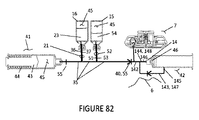
図8に示すように、移送器具3のバイアルアクセス部材21は、移送器具3の内部の流体流路35と連通するための多内腔管34を備え得る。バイアルアクセス部材21は、好ましくは、1つの入口管36と、空気または流体がバイアル12から出るのを許す1本の出口管37を備える。これらの入口管36と出口管37は、別々であり得、区別され得、移送器具3において異なる流体流路に通じ得る。バイアル12は垂直方向において上下逆の位置にあるので、バイアルアクセス部材21の内腔開口38は、入口管36の開口が出口管37の開口より上にあるように、指向され得る。この方位は、上部の入口管36通した圧縮空気または液体の導入と、下部の出口管37を通したバイアル内容物14の排出を許す。さらに、出口管37の開口は、バイアル12の全ての内容物14を出口管37に入れてバイアル12から取り出すために、バイアル12の底の近傍で隔壁19に隣接して位置し得る。
As shown in FIG. 8, the
図9と図10に示すように、移送器具6は、使用者による手順の開始の後、好ましくは自動的に、バイアル15,16内に含まれる内容物14を移して、(必要に応じて)再構成し、混合物を注射装置7へ移すために必要なステップの全てを実行するように構成される。移送器具6は、希釈剤を希釈剤バイアル16から注射可能な粉末剤のバイアル15内に向け、内容物14を移送器具6を通して注射装置7に向けるように、(例えば電池で駆動される)電気的な、または(例えばばねが装備される)機械的に駆動されるポンプのような推進システムまたは複数の推進システムを好ましくは含むように構成される。
As shown in FIGS. 9 and 10, the
図9と図10に示すように、移送器具6はまた、内容物14の移送、再構成、混合、希釈または他の手順と、バイアルホルダー5内のバイアル15,16から注射装置7への移送を実行することを要求される場合に内部の流体流路35の列を含み得る。流体流路35は、柔軟または固いパイプまたは管を含み得る。これらの流体流路35は、バイアル15,16から移送器具6まで薬を向かわせるための逆止弁(フィルタ、流れ絞りまたは他の手段)40も含み得る。
As shown in FIGS. 9 and 10, the
図9と図10に示すように、移送器具6は、内部に可動ばね式ピストンを備えて直接内部の流体流路35に通じている容積可変の圧力室またはシリンダーを含み得る。容積可変室の室ごとの容積は、室の直径とピストンの位置によって定義され得る。移送器具6内の第1の圧力室41は、好ましくは、1〜30ミリリットルの範囲内で製造者によって当初の容積を設定され得る。第1の圧力室41の当初の内容物は、好ましくは空気45を含み得る。容積が製造者によって定められて設定された第1の圧力室41において、ピストン43はばね(圧縮ばね)44で動かされ得る。ばね式のピストン43は、第1の圧力室41で1〜50psiの静的気圧を発生するために十分な大きさと構成であり得る。空気45の体積は、動作中、第1の圧力室41の直径とピストン43のストローク位置に依存する。この圧力はピストン43によって変位する空気45の相対的な体積とばね44によって及ぼされる力に依存する。換言すれば、ばね44によって及ぼされる力と第1の圧力室41内のピストン43の面積の積が第1の圧力室41内の静圧力を決定する。密着高さまたはストロークの開始においてばね44によって及ぼされる力は、移動の最後にばね44によって及ぼされる力よりもずっと大きい場合がある。ばね44は、空気が第1の圧力室41から排出される速度とそして移送器具6内の流体の移送の速度を制御するために、適切な大きさであり得る。第1の圧力室41は、好ましくは、第1の圧力室41から空気45の全てを放出するように構成される。あるいは、第1の圧力室41の流体流路(または出力通路)35の流れ絞り55は、空気45が第1の圧力室41から噴出される速度を制御するのに用いられ得る。
As shown in FIGS. 9 and 10, the
図9と図10に示すように、第2の圧力室42の容積は、製造者によって設定され得る。あるいは、第2の圧力室42のための満たされる容積は、0.5〜30ミリリットルの範囲であり、服用量選択部(または容積制御部、服用量指標)48を用いる使用時に、使用者によって設定され得る。第2の圧力室42のばね式のピストン46は、第2の圧力室42で1〜200psiの圧力を発生するために十分な大きさと構成であり得る。服用選択部48は使用者に、満たされる第2の圧力室42の容積を設定することによって注射装置7で射出されるのに定められた投薬量を選ばせる。服用量選択部48は、いかなる適切な構成でもあり得る。服用量選択部48は、第2の圧力室42内で動かせるプランジャー(または圧力プランジャー・アセンブリ、圧力室プランジャー・アセンブリ)93に直接結合する場合がある。一旦ピストンが満容積設定と一致している位置に達するならば、圧力プランジャー・アセンブリ93の範囲内のトリガー49は第2の圧力室42でピストン46を開放する。望ましい注射投薬量に等しい満容積を定めるために、プランジャー93の位置を決める服用量選択部48を動かすことによって、使用者は2回目の第2の圧力室42における望ましい投薬量を選ぶ。あるいは、プランジャー93の位置は送達服用量と一致している製品ですでに決められており使用者は服用調整をすることなく装置を操作する場合がある。
As shown in FIGS. 9 and 10, the volume of the
図9と図10に示すように、混合と移送を提供する二連バイアルのシステム4のための移送のための移送器具6は、第1のバイアル16と第2のバイアル15を有するバイアルホルダー5、容積可変の第1の圧力室41、容積可変の第2の圧力室42、流体流路35、空気を第1の圧力室41から第1のバイアル16に向けて第1のバイアル16の内容物23を第2の圧力室42に向けその後注射装置7に向けるための逆止弁40を含む。
As shown in FIGS. 9 and 10, the
図8に示すように、使用者によるバイアルホルダー5の移送器具6への完全な挿入と、それに続くバイアルアクセス部材21の隔壁19を通してバイアル12の室内への導入は、図10に示すように、圧力室のトリガー50の開放を許す。
As shown in FIG. 8, a complete insertion into the
図9と図10に示すように、トリガー50の解放は、第1の圧力室のばね44を解放し、第1の圧力室41内で第1の圧力室のピストン43を前進させ、第1の圧力室41内の空気45が、移送器具6の内部の流体流路35を通って、第1のバイアルアクセス部材21の入口管36を通って第1のバイアル16に入るように強制する。より多くの空気45が第1の圧力室41から、そして、入口管36による第1のバイアル16に強制されて、空気45はバイアルホルダー5内にその垂直配置のために第1のバイアル16の頂部まで上がる。第1のバイアル16の増加している気圧は、バイアル16の中の内容物23が第1のバイアルアクセス部材21の出口管37によって、そして、第2のバイアルアクセス部材52の入口管51によって噴出される原因になる。第1のバイアル16から第2のバイアル15に入る内容物23は、液体または粉末薬剤を含む第2のバイアル15の内容物と混合し、第2のバイアルアクセス部材52の出口管53を通って第2の圧力室42内に出る。同様に、再構成の構造でも、第1の圧力室41のピストン(またはプランジャー、送給プランジャー)43は、第2のバイアル15に第1のバイアル16を通して、第1の内容物23と空気45の混合物を押し流し続ける。第2のバイアル15の頂部の増加している気圧は、第2のバイアル15の底の再構成された内容物14が第2の圧力室42へ外に放出される原因になる。第2のバイアル15の内容物14が第2の圧力室42へ外に放出される前に、第1のバイアル16の内容物23の全てを第2のバイアル15に入らせるために、「ポップオフ」または逆止弁40または他のタイプの弁が第2のバイアルアクセス部材52の出口管53に存在する場合がある。第1の圧力室41から実質的に全部の空気45を押しているピストン43と一致している圧力まで、弁は開かない。第2のバイアル15の内容物54が内容物14が第2のバイアル15を出る前に第1のバイアル16の内容物23を完全に混ぜ合わせ得、第2の圧力室42に圧力をかけることを、これは確実とする。あるいは、流れ絞り55が、移送を延ばして、混合時間を増やすために、流体流路35で使われる場合がある。
As shown in FIGS. 9 and 10, the release of the trigger 50 releases the
図9と図10に示すように、注射可能な内容物14は再構成の後第2のバイアル15から第2の圧力室42に流れ、使用者または製造者によって服用量選択部48を用いて選択された望ましい投薬量に一致する、ピストン46に許される限度まで第2の圧力室42を充填する。第2の圧力室42の望ましい体積が達成された時、第2の圧力室のトリガー49はばね47を解放し、ピストン46を進めるよう強制し、選択された量の内容物14を加圧下で注射装置7内に放出する。服用量選択部48で示される服用量の較正と使用者によって受け取られる実際の服用量は、移送器具6の内部の流体流路35で流体の損失を考慮に入れることを要求され得る。注射装置7は、現在充填され、移送器具6から取り外す準備ができている。
As shown in FIGS. 9 and 10, the
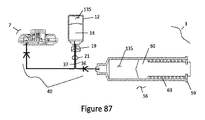
図11と図12に示すように、混合を実行せずに1つのバイアル15から注射装置7へ内容物14を移送するだけである、単一のバイアルのシステム1内の別の移送器具3が提供される。この別の移送器具3は、注射装置7にバイアル15から内容物14を向けるために、単一のバイアル15を有するバイアルホルダー2、容積可変の圧力室56、流体流路35と逆止弁40を含む。バイアルアクセス部材21の入口管36は、空気58をバイアル15に入らせるために、環境57に出される。バイアルアクセス部材21の出口管37は、圧力室56に接続されている。
As shown in FIGS. 11 and 12, from one
図11と図12に示すように、使用者による移送器具3へのバイアルホルダー2の完全な挿入は、バイアル15の隔壁19を通して、バイアルアクセス部材21の導入がバイアル15の内容物14にアクセスさせる。これも圧力室のトリガー49の解放を誘発する。トリガー(圧力解放トリガー)49は、引き込みばね61に接続された圧力室56内でプランジャー60を解放する。引き込みばね61はプランジャー60が内容物14をバイアル15から引き込み納め、圧力室56を充填するように強制する。圧力室56によって引き込まれる内容物14の特定の量は、プランジャー60の引き込みを制限することによって、製造者によって設定され得る。さらに、圧力室56は、プランジャー60を最大移動距離まで引き込むことによって、全ての内容物14をバイアル15から引き込むように構成され得る。一旦プランジャー60が圧力室56の中で設定ポジションに着くと、それは、内容物14を圧力室56から出て注射装置7内に強制するように投与ばね63を解放する投与トリガー62と相互作用する。逆止弁40は、内容物14がバイアル15に戻るのを防ぐために使用され得る。
As shown in FIGS. 11 and 12, the complete insertion of the
図13に示すように、混合と移送を提供する二連バイアルのシステム4のための別の移送器具6は、第1のバイアル16と第2のバイアル15を含むバイアルホルダー5と、可変容積の圧力室56と、流体流路35と、第1のバイアル16の内容物23を第2のバイアル15内に向けてその結果の内容物14を圧力室56に向けるための逆止弁40とを含む。この内容物14はその後、第2のバイアル15に移送し戻され、その後、注射装置7に移送される。この実施の形態では、第1のバイアルアクセス部材21の入口管36は、空気58をバイアル16に入らせるために、環境57に出される。第1のバイアルアクセス部材21の出口管37は、第2のバイアルアクセス部材52の入口管51に接続している。第2のバイアルアクセス部材52の出口管53は、容積可変の圧力室56に接続している。流体流路35は、第1のバイアルアクセス部材21、第2のバイアルアクセス部材52と注射装置7の間に位置する逆止弁40を含む。
As shown in FIG. 13, another
図13に示すように、使用者による移送器具6へのバイアルホルダー5の完全な挿入は、バイアル15、16の隔壁19を通して、バイアルアクセス部材21,52の導入によって各々のバイアル15、16の内容物23,54にアクセスさせる。これも、圧力室トリガーの解放を誘発する。引き込みばねに接続された圧力室56内でプランジャー60を解放する。引き込みばねは、第1のバイアル16から内容物23を引き込み納め、第2のバイアル15を充填するようにプランジャー60を強制する。この充填によって、第1のバイアル16からの内容物23と第2のバイアル15の内容物54との混合が起きる。内容物23の全てが第1のバイアル16から取り出されるまで、第2のバイアル15からの結果として生じる内容物14は圧力室56を充填する。第1のバイアル16が第2のバイアル15を満たす速度は、逆止弁40または流れ絞り55で調整され得る。第1のバイアル16から引き込まれる内容物23の量は、製造者によって圧力室56で設定され得る。一旦圧力室56のプランジャー60が圧力室56内で設定位置に着くと、それは、内容物14を圧力室56から出して第2のバイアル15に戻すように強制するように投与ばねを解放する投与トリガーと相互作用する。これは第1のバイアル16からの内容物23と第2のバイアル15からの内容物14とをさらに混合させるために有利である。圧力室56からの全ての内容物14が投与されると、内容物14が注射装置7に移送される。圧力室56の容積は、追加の空気58が圧力室56内に引き込まれるように、全流体体積よりも大きく設定され得る。追加の空気58は、全ての内容物14が注射装置7に移送されるか、そうでなければ流体流路35内にあることを保証するために役立ち得る。逆止弁40は、第2のバイアル15から注射装置7への内容物14の移送の間に内容物14が第1のバイアルに戻るのを防ぐために、流体流路35内のどこにでも使用され得る。注射装置7への内容物14の移送の前に、第2のバイアル15内での混合時間を制御するために、流体流路35のどこにでも流れ絞り55は使用され得る。
As shown in FIG. 13, the complete insertion of the
図14に示すように、混合と移送を提供する二連バイアルのシステム4のための別の移送器具6は、第1のバイアル16と第2のバイアル15とを有するバイアルホルダー5と、第1の可変容積の圧力室56と、可変容積の第2の圧力室42と、流体流路35と、第1のバイアル16の内容物を第2のバイアル15に向けてその結果の内容物14を圧力室56に向ける逆止弁40とを含む。内容物14はその後、第1の圧力室56から第2の圧力室42へ移送され、その後注射装置7に移送される。この実施の形態では、第1のバイアルアクセス部材21の入口管36は、空気58をバイアル16に入らせるために、環境57に出されている。第1のバイアルアクセス部材21の出口管37は、第2のバイアルアクセス部材52の入口管51に接続されている。第2のバイアルアクセス部材52の出口管53は、第1の容積可変の圧力室56に接続している。流体流路35は、第1のバイアルアクセス部材21と第2のバイアルアクセス部材52と第2の圧力室42と注射装置7の間に存在する逆止弁40を含む。
As shown in FIG. 14, another
図14に示すように、使用者による移送器具6へのバイアルホルダー5の完全な挿入は、バイアル15、16の隔壁19を通して、バイアルアクセス部材21,52の導入によって各々のバイアル15、16の内容物23,54にアクセスさせる。これも圧力室トリガーの解放を誘発する。圧力室トリガーは、引き込みばねに接続された圧力室56内でプランジャー60を解放する。引き込みばねは、第1のバイアル16から内容物23を引き込み納め、第2のバイアル15を充填するようにプランジャー60を強制する。この充填によっても、第1のバイアル16からの内容物23と第2のバイアル15の内容物54とを混合させる。内容物23の全てが第1のバイアル16から取り出されるまで、第2のバイアル15からの結果として生じる内容物14は圧力室56を充填する。第1のバイアル16が第2のバイアル15を満たす速度は、逆止弁40または流れ絞り55で調整され得る。第1のバイアル16から引き込まれる内容物23の量は、製造者によって圧力室56で設定され得る。一旦圧力室56のプランジャー60が圧力室56内で設定位置に着くと、それは、内容物14を圧力室56から出して第2のバイアル15に戻すように強制するように投与ばねを解放する投与トリガーと相互作用する。圧力室56からすべての内容物14が第2のバイアル15に投与されると、内容物14が第2の圧力室42に移送され、望ましい服用量に一致する、使用者または製造者によって選択されたピストン46によって許される限度まで第2の圧力室42を充填する。第2の圧力室の所望の体積が達成されると、第2の圧力室のトリガーが第2の圧力室ばねを解放し、ピストン46を進めるよう強制し、選択された体積の注射可能な内容物14を加圧下で注射装置に放出する。逆止弁40は、第2のバイアル15から第2の圧力室42と注射装置7への内容物14の移送の間に内容物14が第1のバイアルに戻るのを防ぐために、流体流路35内のどこにでも使用され得る。第2の圧力室42への内容物14の移送の前に、第2のバイアル15内での混合時間を制御するために、流体流路35のどこにでも流れ絞り55は使用され得る。
As shown in FIG. 14, the complete insertion of the
図15に示すように、混合と移送を提供する二連バイアルのシステム4のための別の移送器具6は、第1のバイアル16と第2のバイアル15とを有するバイアルホルダー5と、可変容積圧力室56と、二連内腔接続具94と、入口流路95と、出口流路96と、プランジャー60の圧力室56内での引き込みの間に第1のバイアル16の内容物23を、入口流路95を通って圧力室56に向けるための逆止弁40とを含む。圧力室56内で最大に引き込んだ後のプランジャー60の前進は、流体の内容物23を圧力室56から第2のバイアル15内に流し、第2のバイアル15の内容物と混合させ、その結果の内容物14は注射装置7内に流れる。出口流路96内の逆止弁40は、引き込み相の間に第2のバイアル15の内容物56が圧力室56に引かれるのを妨げるであろう。プランジャー60の前進の間、入口流路95内の逆止弁40は、圧力室56内の流体の内容物23が第1のバイアル16へ移送し戻されることを防ぐ。第2のバイアル15と注射装置7からの流体流路35内の逆止弁は、混合物が注射装置7から第2のバイアルに移送し戻されることを防ぐ。流れ絞り55は、流体の移送速度を制御するために、流体流路35,95,96のどこにでも使用され得る。あるいは、二連内腔接続具94の使用は、流体を異なる流体流路から取り出し、進めるために、単一バイアルの移送のシステム1にも同様に使用され得る。
As shown in FIG. 15, another
図16に示すように、上述の実施の形態における圧力室は、重力を利用するために、通常の注射器と比較して、偏向させる、または、中心をずらす出口ポート64とともに構成され得る。圧力室59が移送過程の間に内容物14で満たされると、内容物14に加えて圧力室59にもたらされる若干の空気58がある場合がある。内容物14を圧力室59から放出する過程の間に、空気58または内容物14がいつ圧力室59から放出されるかという順序を制御することが有利であり得る。例えば、圧力室59からの内容物14の放出の間に圧力室59の出口ポート64が下向きにされると、気泡は圧力室59の上に方向づけられるので、全ての内容物14は放出され、その後、残っている空気58が最後に放出される。逆に、圧力室59からの内容物14の放出の間に圧力室59の出口ポート64が上向きにされると、全ての空気58がまず放出され、その後、残っている内容物14が最後に放出される。これは注射装置7への内容物14の移送の間に、望まれない空気58をラインから取り除くために親水または疎水フィルタを用いる場合に、特に有利である。
As shown in FIG. 16, the pressure chamber in the above-described embodiments may be configured with an
移送器具は、混合を強化するために、いろいろな装置または手順を使用する場合がある。例えば、移送器具は希釈剤を渦を巻くように薬剤含有バイアルに注射し得、および/または、例えば混合ボール、ボート錐またはプロペラ、振動している注射管といった、動的または静的混合器のような混合強化部材を使用または導入し得る。これらの技術は第2のバイアルまたは注射器の1つにおいて使用され得る。さらに、移送器具は第2のバイアルアクセス部材と出口管と圧力室との間に、上述の混合の強化の技術と手順をさせるための中間室を有し得る。移送器具はまた、例えば注射可能なバイアルを回すことによって、乱気流を誘発して、混合を強化するために注射可能な薬のバイアルを導入するように動かすように構成され得る。より大きな混合のために移送時間を増やすために、流れ絞りは、空気または薬の流路で用いられる場合がある。 The transfer device may use various devices or procedures to enhance mixing. For example, the transfer device may inject the diluent swirl into the drug-containing vial and / or of a dynamic or static mixer, such as a mixing bowl, boat cone or propeller, oscillating injection tube. Such mixing enhancement members may be used or introduced. These techniques can be used in one of the second vials or syringes. Further, the transfer device may have an intermediate chamber between the second vial access member, the outlet tube and the pressure chamber to allow the mixing enhancement techniques and procedures described above. The transfer device can also be configured to induce turbulence and move to introduce a vial of injectable drug to enhance mixing, for example by rotating the injectable vial. Flow restrictors may be used in the air or drug flow path to increase transfer time for greater mixing.
図16と図17に示すように、移送器具3の任意の別の特徴は、注射装置7に導入される前に粒子を取り除くために注射可能な内容物14をろ過するための、注射可能な薬の流体流路35内のフィルタ65である。フィルタ65は好ましくない微粒子を除去するために十分に小さい孔の大きさまたは効果的な孔の大きさである膜、深さフィルタまたは他の適当なろ過媒体であり得、好ましくない微粒子は、限定でないが、移送器具3によって注射可能な薬が再構成される状況における溶解されていない注射可能な薬を含み得る。
As shown in FIGS. 16 and 17, another optional feature of the
図16と図17に示すように、注射可能薬物のバイアル15からの回収は、バイアル15への空気(置換空気)58の導入が要求されるか強化する場合がある。本主題の別の局面においては、移送器具3は、注射可能な内容物14が引き込まれる時に空気(置換空気)58のバイアル15内部への導入をさせるようにバイアルの内部と連通する置換空気流路または穴66を含み得る。先に議論したように、バイアルの隔壁19を突き刺すバイアルアクセス部材21は、入口管36と出口管37を有し得、1つは注射可能な内容物14がバイアル15から流れるためであり、1つはバイアル15内に空気(置換空気)58が流れるためである。空気(置換空気)58は、移送器具3内の、空気(置換空気)58をろ過するための、実際のまたは実効の孔の大きさが約0.22μm以下である膜またはフィルタ(深さフィルタ、無菌フィルタ)65のようなフィルタ65を含み得る流体流路35を流れる。そのような孔の大きさは、空気(置換空気)58によってバイアル15に病原体が導入されることを防ぐために十分に小さく、注射可能な内容物14の汚染の危険性を低減する。
As shown in FIGS. 16 and 17, the recovery of injectable drug from
図16と図17に示すように、移送器具3は、バイアル15から注射装置7まで延びる注射可能な内容物14の流体流路35と連通する空気除去具67を含み得る。空気除去具67のようなものは、注射可能な内容物14が注射装置7に導入される前に注射可能な内容物14の流体流路35から空気58を除去する、注射可能な内容物14の流体流路35の他の構成の気泡トラップ、エアギャップを含み得る。空気除去具67は、疎水フィルタ6または疎水フィルタ68と親水フィルタ69との組合せで構成され得る。疎水フィルタ68は、内容物14の通路ではなく移送器具3からの空気の排出をさせる。親水フィルタ69は、粒子または空気58ではなく内容物14の通過を許す。流体流路35内の親水フィルタ69の位置の組合せは、好ましくは、全ての空気58を移送過程で除去する。
As shown in FIGS. 16 and 17, the
図18と図19に示すように、移送器具6には、上述のものだけでなくさらなる特徴も有する場合がある。そのような特徴の1つは、服用量選択部48とバイアルホルダードッキング領域29の間の連結装置70である。これは、例えば、投薬量が選ばれるまで、使用者がバイアルをバイアルホルダードッキング領域29に詰めるのを防ぐ機械な干渉部材97でありえる。機械的に、服用量選択部48は、服用量選択部48が服用量選択位置に動かされて積載許可位置に動くまでバイアルホルダー5のバイアルホルダードッキング領域29への挿入を防止するために通常、積載防止位置にあるバイアルホルダードッキング領域29において干渉部材97に連結さえ得る。当然のことながら、注射可能薬物のすべてが注射されるべき一回の服用量が入っているバイアルまたは単一のバイアルから注射可能な薬を投与するためには、移送器具は服用量選択の能力を含む必要はない。
As shown in FIGS. 18 and 19, the
図18と図19に示すように、移送器具6は、移送器具6と注射装置7との間に、充填される前に注射装置が取り外されることを防止し、注射装置7が移送器具6から取り外される準備できたことを示すために連結部材71を含み得る。機械的には、ロックピン72は移送器具6によって注射装置7が完全に充填される前の取り外しを防止するために注射装置7に連結され得る。ロックピン72は、移送器具6の部分であり得、第2の圧力室42においてピストンと連通し得る。第2の圧力室42が全ての注射可能な内容物14を放出すると、これは機械的にロックピン72が注射装置7から遠ざかるように動くように誘発し、使用者による移送器具6からの注射装置7の取り外しを許可する。
As shown in FIGS. 18 and 19, the
図18に示すように、移送器具6は移送器具6と注射装置7との間に注射装置7をどのように移送器具6から取り外すかを制御するための連結装置を含み得る。機械的には、注射装置7上のフランジや他の突起73は移送器具6の切り込みと機械的に連結し得る。この構成は、使用者による取り外しにおいて、移送器具6に対する注射装置7の一方向の回転を許す。
As shown in FIG. 18, the
図18と図19に示すように、移送器具6は、注射装置7が起動されることを防ぐロックするための特徴を含み得る。例えば、ロックピン72やアーチや他の手段のような機械的な干渉部材は、移送器具6の外に拡張し、上の位置で作動装置またはボタンで機械的に注射装置7をロックし得る。あるいは、機械的な干渉部材72は、移送器具6上で注射装置7へのアクセスを防ぐために注射装置7全体を覆う遮蔽部材であり得る。アーチまたは遮蔽部材(機械的な干渉部材72)は、移送器具6の一部である得、第2の圧力室42に連通し得る。第2の圧力室42が注射装置7に内容物14の全てを放出したとき、機械的にアーチまたは遮蔽部材(機械的な干渉部材72)のロックを外すことを誘発し、注射装置7から離れさせることを誘発し得る。これは、使用者による注射装置7へのアクセスと移送器具6からの除去を許す。
As shown in FIGS. 18 and 19, the
移送器具の別の任意の特徴は、注射装置の移送器具からの急速な解放を許し注射装置が移送器具に再度接触することを防止するための、充填ポートまたは移送器具と注射装置の間のアクセス部材の急速な解放である。注射装置が充填され、移送器具から装置を取り外す準備ができた後、使用者は注射装置を取り外し得る。移送器具の充填管(またはアクセス部材)83は、注射装置が移送器具から取り外される時に負荷を掛けられるばねであり得、充填管83はばねで移送器具に下ろされる。このことは、充填ポート81において注射装置の不注意な漏れを防ぎ、注射装置の充填ポート81からの充填管83の急速な解放を許す。これはまた、使用者にとって充填管83にアクセスできないようにし、注射装置が移送器具に再度接触することを防ぐ。
Another optional feature of the transfer device is a filling port or access between the transfer device and the injection device to allow rapid release of the injection device from the transfer device and prevent re-contact of the injection device with the transfer device. Rapid release of parts. The user may remove the injection device after the injection device is filled and ready to be removed from the transfer device. The fill tube ( or access member ) 83 of the transfer device can be a spring that is loaded when the injection device is removed from the transfer device, and the fill tube 83 is spring loaded onto the transfer device. This prevents inadvertent leakage of the injection device at the
図18に示すように、注射装置7と移送器具6は、好ましくは、注射装置7の取り外し可能な取り付けのために構成される。現在の実施形態では、移送器具6内での注射可能な内容物14の第2の圧力室42から注射装置7への移送と移送器具6上の連結部材71の解放の後、注射装置7は、対象の皮膚への適用のために、移送器具6の注射装置ドッキングステーション30から分離するように準備される。上述のように、ここの記載された別の実施形態は、注射可能な流体の単一圧力室から注射装置への直接の移送を含む。
As shown in FIG. 18, the
図20に示すように、注射装置7は、いかなる適切な構成でも有り得る。先に説明したように、注射装置は、全体がここに参照として組み込まれる2010年4月21日出願の米国特許出願第61/326,492、2012年9月27日出願の米国特許出願第13/637,756、2012年9月24日出願の米国特許出願第61/704,922で記述される注射装置の特徴の一つ以上を有利に使用し得る。
As shown in FIG. 20, the
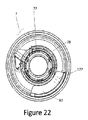
図20〜22に示すように、注射装置7は、上面75と下面76とを有し、使用者によって作動された時に注射針またはカニューレを突き出す、一般的に、偏平な、皿状のハウジング74を備える。注射を開始するための上面75は作動装置またはボタン77と、注射装置7内の注射可能な流体(薬、注射可能な薬物)79の量を確認するために対象者または医療専門家が拡張可能部材78を視認するためのハウジング74の透明部分80を有する。例えば、使用者は、注射が開始されたか、完結されたかを決定し得る。より好ましくは、拡張可能部材78および/またはハウジング74の透明部分80は、患者や医療専門家が残っている注射可能な流体79の量をよいよい精度で、例えば約50%完了または約75%完了のように視覚的に決定できるように線の印127等によって目盛を付けられ得る。さらに、拡張可能部材78は、残っている注射可能な流体79の量を示すために、それ自身、他のハウジング74の特徴を含み得、または、相互作用し得る。例えば、注射装置7が流体79で充填されると、透明部分80は、限定されないが、例えば緑のような1つの色を示す。注射装置7の流体79が空になると、透明部分80は、限定されないが赤のような別の色を示し得る。投与の途中には、透明部分80は色の組合せを示し得る。
As shown in FIGS. 20-22, the
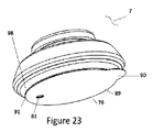
図23〜25に示すように、注射装置7の下面76は充填ポート81と投与ポート82を含む。充填ポート81は、流体79を注射装置7へ移すために移送器具が充填管83を充填することを許す境界面である。投与ポート82も拡張可能部材78から放出された注射可能な流体79と針(投与針、注射針)85の間に流体チャンネル(内部流路86)を含む。充填ポート81と投与ポート82は流体チャンネル(内部流路86)を通して直接、連通し得、または単一のポートに結合され得る。
As shown in FIGS. 23-25, the
図23〜25に示すように、注射装置7が移送器具6から取り外され、充填ポート81は充填管83から取り除かれるとき、注射装置は、好ましくは、加圧された注射可能な流体79が注射装置7から漏れるのを防ぐための逆止弁87を含む充填ポート81を含み得る。
When the
図23〜25に示すように、注射装置7は、注射器の挿入を受け入れるように構成される充填ポート81も有し得る。この注射器は、ルアー取り付け具または針で構成され得る。充填ポート81の構成は、使用者による注射装置の手動の充填を許す。移送器具6はまだ使用され得るが、この構成では必要とされないであろう。
As shown in Figures 23-25, the
図23〜25に示すように、注射装置7は取り付けられた管または標準的な針ポートを経由して静脈カニューレに直接接続されるように構成される投与ポート82も有し得る。
As shown in Figures 23-25, the
図23〜25に示すように、注射が完了するまで一時的に注射装置7を対象の皮膚に固定するために、注射装置7の下面76は接着剤88を運ぶ。注射装置7の取り外しの間、注射装置7を患者の皮膚に接着するために使用し得るように、注射装置7の下面76に接着剤88の面を露出させて、接着テープ裏地89が自動的に取り外され得る。あるいは、接着テープ裏地89は、注射装置7の皮膚への接着前に使用者が手で取り外すために引くためのタブ90を有し得る。あるいは、このタブは、注射装置7の取り外し時にテープ裏地が自動的に取り外されるように移送器具6
の表面に取り付けられ得る。
23-25, the
Can be attached to the surface of.
図23〜25に示すように、注射装置7は、下面(基部)76の下面を超えて延びる接着テープの接着フランジ91を有し得る。接着剤(接着テープ)88の接着フランジ91は、注射装置7と皮膚表面との間で歪みの緩和の働きをし得、注射装置7が皮膚から偶然取り外される危険を低減する。換言すれば、接続部内に入るワイヤ上の同様の接着性の歪み緩和と同様、延ばされた接着フランジ91は、接着剤88と皮膚の境界面において応力集中を低減するために、接着剤88と注射装置7の下面(基部)76との接続点の両側に荷重を分配するように働く。
As shown in FIGS. 23-25, the
図23〜25に示すように、注射装置は、使用者がさらなる使用者の干渉なしに、注射装置7を皮膚にしっかり固定するように、接着フランジ91を、接着剤88を皮膚にしっかり付けるように押すテーパー形状の下面98を有するように構成し得る。注射装置7を皮膚に押し付ける時、人の皮膚の迎合性を用いて、注射装置7のテーパー形状の下側表面98は接着剤88のフランジ91を皮膚に効果的に押しつけるが、フランジ91の上側の露出された面は露出された接着性を有さず、従ってテーパー形状の下面98のその部分には取り付けられない。使用者は、注射装置7を皮膚に確実に付けるためにフランジ91の周囲で指を走らせる必要がなく、接着剤88の付着方法を相当簡単にする。
As shown in Figures 23-25, the injection device provides an
図23〜25に示すように、注射装置7は、適用の間、注射装置7の改良された取り付けを許すために、剛性である代わりに、柔軟または追随性のある下面76を有し得る。
As shown in FIGS. 23-25, the
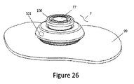
図26〜28に示すように、注射装置7が皮膚99に押しつけられるか接着された後、安全機構またはロックアウト機構は自動的に解放され得、注射装置7は射出(注射)の準備がされる。換言すれば、注射装置7は、皮膚上に配置されるまでは起動される(ロックアウトされる)ことを防がれる。あるいは、使用者は注射装置が射出(注射)の準備をするように、手動で安全ピン、安全スリーブやカラーのような安全機構(安全装置)100を取り外し得る。安全機構100は受動的または能動的に、使用者によって手動でまたは注射装置7によって自動で誘発され得る。
As shown in FIGS. 26-28, after the
図26〜28に示すように、注射装置7は作動装置またはボタン77と視覚的指示器101を組み合わせて、移送器具から取り外された後に注射装置7の状態を定義するために使用し得る。例えば、ボタン77が上の位置にあり指示器101が限定されないが緑のような1色を有する時には、注射装置7は注射開始の準備ができている状態であることを示し得る。さらに、ボタン77がボタン頂部103とは異なる色を有する側壁102を有し得る。ボタン77が押されていると、使用者はボタン77の側壁102を見ることができない。これは、注射装置7が使用中であることを示し得る。薬の注射が完了すると、注射装置7は使用者に警戒を促す場合がある。この警報は、視覚的な指標、聞き取れる音、機械の運動または組合せの形であり得る。ボタン77は、理想的には、ロックアウト位置に現れる時、使用者に聞きとれる、視認できる、触角型のフィードバックを与えるように設計されている。注射装置7は、ボタン77が上の位置にあり指示器(指示窓)101が注射装置が空であることを示すことによって、投与が完了し、満量が患者に送達されたことを使用者に示し得る。例えば、ボタン77が上の位置にあり、指示器101が限定されないが赤のような異なる色を示す時、注射装置7は注射を完了したことを示し得る。
As shown in FIGS. 26-28, the
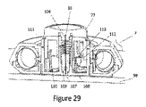
図29〜31に示すように、注射装置7は、作動装置または使用者が注射を始めるために注射装置7で押すボタン77を備え得る。ボタン77は、オン/オフ動作のスイッチであるように、すなわち、照明スイッチのように開と閉の2つの状態のみを有するように構成され得る。これは、使用者がボタン77を途中まで押して注射装置7を起動させないことを防ぎ得る。一旦起動されると、この「照明スイッチ」型のボタン77は、使用者のボタン77の操作とは独立して、針85を皮膚99にすばやく挿入するであろう。あるいは、ボタン77は使用者がゆっくりと針85を皮膚99に挿入することを許すよう、連続運動を有し得る。ボタン77はボタン77と針85を作製している接着剤104を用いて、好ましくは直接、針85に結合され得る。
As shown in FIGS. 29-31, the
図29〜31に示すように、注射装置7は、図30に示すように最初の位置または深さに進むようにボタン77が起動されると、針85に皮膚99中へ移動させ、図31に示すように、自動的に第2の深さの位置にわずかに引き込む。図30に示す第1の深さは、作動の間、ボタン77の移動によって到達される。第1の深さは、ボタン77内の構成105によって、注射装置7の基部106と直接接触して制御され得る。針85の最終的な深さは、皮下注射にふさわしい。あるいは、針85の最終的な深さは、皮内注射のために減らされる場合がある。あるいは、針85の最終的な深さは、筋肉注射のために増やされる場合がある。最初の深さに達すると、即座に、針85は図31で示すように第2の深さへ引き込まれる。第2の深さへの針の引き込み距離は、0.1〜2mmの範囲内である。この引き込み機能は、針85が最初の挿入過程の間に組織によってブロックされるのを防ぐために好ましい。この組織の妨害は、克服するために非常に高い圧力を要求し得、注射装置7が薬を送達するのを妨害し得る。第1の位置から第2の位置への針85の引き込みは、針先端107よりも前方に空いたポケットを作り出し、針85からの薬剤の流れを開始する圧力を低減することを可能にする。針からの薬の流れの開始のためのこの減圧は、注射の間、比較的恒常的な圧力を維持するために、注射装置7のために好ましい。
29-31, the
図29〜31に示すように、注射装置7は、横穴108のある針85を含み得る。図31に示すように、一旦、注射装置7のボタン77が完全に押されると、針85は投与ポート82を通って終わりまで皮膚99に完全に挿入され、注射装置7は注射可能薬物の投与を開始する。ボタン77が完全に押されるまでは、横穴108と、従って針85の内腔は投与ポート82の流体チャンネル86とは連通していない。横穴108と針先端107の両方は隔壁109内に保持される。隔壁109内で保持されている横穴108と針先端107において、全ての薬経路は、使用の時まで無菌にしておかれる。ボタン77は完全に押されて針85が投与位置にあると、針85の横穴108は投与ポート82の流体チャンネル86と連通し、液体の注射が始まる。
As shown in FIGS. 29-31, the
図29〜31に示すように、隔壁109は、針先端107と横穴108が投与の前後において注射可能な薬から封止されることの利点を提供する。針85の針先端107と横穴108を注射の最後に封止することは、特に、投与の最後および/または皮膚表面からの取り外しの後に、注射可能な薬が注射装置7から滴ることを防ぐために有利である。また、皮膚内に入る前に針の穴に汚物が入ることを防ぐ。隔壁109は、一旦針85が穴を開けた時に封止することを可能にするいかなる適切な材質によっても作製され得る。隔壁109の材質は好ましくはシリコーンである。あるいは、隔壁の具体的な構成は、ブロモブチル、クロロブチル、イソプレン、ポリイソプレン、SBR、ポリブタジエン、EPDM、天然ゴムとシリコーンを含むがこれに限らず異なる材料の混合物である場合もある。あるいは、投与ポート82を含む流体流路86は、シリコーンを有する上述の隔壁を生成するために射出成型される硬質プラスチックであり得る。
29-31, the
図29〜31に示すように、投与ポート82の隔壁109は、注射領域で皮膚99の表面上で加圧するために、注射装置7の下面からわずかに皮膚99の表面内に突出し得る。針が引き込まれた後の投与ポート82による皮膚99の表面へのこの圧力は、一般に反動と呼ばれる、注射可能な薬が注射領域から出てくることを除去し得る。
As shown in FIG. 29 to 31, the
図29〜31に示すように、注射装置7は、ロック機能を実行するためのボタン77に係合するばねタブ110のセットを含み得る。図29に示すように、ボタン77を第1の上の位置または射出前位置に配置するために、ボタン77内の切り込み111内にロックするために、ばねタブ110は偏向している。切り込み111の形状とばねタブ110は、上述の照明スイッチの動作を生みだすために役立つ。この照明スイッチの動作はばねタブ110に対するボタン77の置き換えと、切り込み111の表面の嵌合によって達成される。
As shown in FIGS. 29-31, the
図29〜31に示すように、注射装置7はロック機能を実行するために、注射装置7内でボタン77と相互作用するばねタブ112を含み得、ボタン77が第1の深さに作動して、第2の深さまたは投与位置に戻るようにわずかに引き込まれるとき、ボタン77内の切り込み機能113はばねタブ112に、注射装置7が投与を完了するまでボタン77を投与位置に保持することを許す。
29-31, the
図32〜33に示すように、いつ流体79の全てが拡張可能部材78から放出されて注射装置7が投与を完了したか感知するために、注射装置7は、送達指示または空指示器114の端部を含み得る。空指示器114は、流体の全てが放出された後、拡張可能部材78が空気を抜かれた状態にある時、出口ポートにおいて拡張可能部材78が滑るスロットまたは他の開口115を有するように構成され得る。空指示器には2つの状態があり得る。図32に示すように、拡張可能部材78が流体79で充填され、スロットまたは開口115の中に収容されない、空指示器は第1の位置または外に偏向された状態にあり得る。第1の状態は、拡張可能部材78の直径が、内部に含まれる残留する流体79によってその最低限より大きいとき、空でない状態に言い換えられる。図33に示すように、拡張可能部材78がスロットまたは開口115の中に部分的に、または、完全に含まれるとき、空指示器114は第2の位置または中に偏向された状態にあり得る。直径が最低限であるとき、第2の位置は拡張可能部材78の空の状態に言い換えられる。
As shown in FIGS. 32-33, the
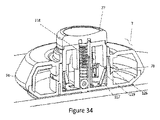
図32〜33に示すように、注射装置7は、投与の最後に自動で針を引き込む機構を含み得る。この機構は、上述のように、ばねタブ112、ボタンの切り込み機能113と空指示器114の間で直接の結合を含む。拡張可能部材78が流体79で満たされ、そして、図33に示すようにボタン77が第1の射出前位置から第2の投与位置に押し込まれる時、ボタン77の切り込み機能113はばねタブ112に、注射装置7が投与を完了するまでボタン77を投与位置に保持することを許す。ばねタブ112も直接、当然第1の位置または外に偏向した位置にある空指示器114に結合され得る。ボタン77を第2の位置または投与位置に押す動きは、ボタン77内のポスト機能116に、空指示器114に第2の位置または中に偏向することを促すように、ばねタブ112に偏向または初荷重を与えることを許す。しかしながら、拡張可能部材78は注射可能な流体79で当初充填されており、直径が大きいので、図32に示すように、空指示器114は第2の位置または中に偏向した状態に動くことはできない。ボタン77が押されたあと、前述のように拡張可能部材78から針を通って流体79が放出し始める。一旦、拡張可能部材78が流体79の全てを放出して、最小限の直径でいるならば、空指示器114(ばねタブ112からの初荷重下で)は図33に示すように第2の位置または中に偏向した状態へ移る。直接、空指示器114にも結合するばねタブ112は、空指示器114とともに動く。この動きは、図34に示すように、投与が完了した後にボタン77(と針)を採集位置または射出後位置に上げるために、ばねタブ112をボタン77内の切り込み機能113から解放する。
As shown in FIGS. 32-33, the
図34に示すように、ロックアウトばねタブ117は、注射が完了しボタン77が解放されてボタン77が戻りばね118によって最終位置または射出後位置に戻るように促されるとき、ロック機能を実行するために、ボタン77と注射装置7内で相互作用し得る。最終位置または射出後位置(図34)における注射装置7の頂部に対するボタン77の高さは、射出前位置(図29)よりも高い場合がある。ロックアウトばねタブ117の端部はハウジング74内で、ボタン77を上の位置または射出後位置にロックしてボタン77が再び作動し始めないように、ボタン77の外径表面119に向かって動く。
As shown in FIG. 34, the
図34に示すように、注射装置7は、第1の上の位置または射出後位置にボタンを偏向させるために、ボタン77と相互作用する戻りばね118を含み得る。ボタンが第2の深さまたは投与位置に下げられる時、戻りばね118は圧縮されて、さらに偏向または予荷重を引き起こす。投与期間の最後に、上述のように投与が完了した後、ボタン77は第2の深さまたは投与位置(図31)からロック解除されて、最終位置または射出後位置に上げられる。ボタン77を最終位置または射出後位置に上がるように強制するものは戻りばね118の偏向である。
As shown in FIG. 34, the
図34〜35に示すように、皮膚99からの注射装置7の除去と同時に、注射装置7は好ましくはロックアウトされる。そして、針への破壊的でない接近または注射装置7の再利用を妨げる。注射装置7は、完全な服用量が送達されたことを使用者に知らせ得る。この指示は、視覚的な指示器、聞き取れる音、機械の運動または組合せの形であり得る。
Upon removal of the
図35に示すように、皮膚99からの注射装置7の除去と同時に、包帯120は注射装置7から解放され、皮膚99の表面で残る場合がある。包帯を注射装置7に付ける接着剤より皮膚により強く付ける包帯部の接着剤の使用によって影響され得る。このようにハウジングが皮膚から持ち上げられるとき、包帯120は、ここに参照によって全体が組み込まれる米国特許第7,637,891号と2009年12月4日出願の米国特許出願第12/630,996に記載されるように、注射領域の上に残る。
Upon removal of the
図36〜39に示すように、注射装置7は、好ましくは拡張可能部材78と充填ポート81と投与ポート82に組み付けられるマニホールド121を含み得、注射装置7の拡張可能部材78と充填ポート81と投与ポート82の間の直接的な流体連通を提供する。上述のように、拡張可能部材78が充填と全流体79の拡張可能部材78の外への放出を容易にするように大きな直径であるように、マニホールド121は拡張可能部材78に組み付けられて端部に構成され得る。拡張可能部材78の中と外に流体を流れさせるために、マニホールド121は内部の流路122を望ましくは含み得る。マニホールド121は注射可能な流体の流路122内で、拡張可能部材78に導入される前後で粒子を除去するために注射可能な流体79をろ過するためにフィルタ123とともに構成され得る。フィルタ123は好ましくない微粒子を除去するために十分に少ない孔の大きさまたは効果的な孔の大きさである膜、深さフィルタまたは他の適当なろ過媒体で有り得る。限定ではないが好ましくない微粒子は、注射可能な流体79が移送器具によって再構成される状況では、溶解していない注射可能な流体79を含み得る。マニホールド121はまた、除去または空気のためにフィルタ123で構成され得る。そのようなフィルタ(空気除去フィルタ)123は、拡張可能部材78に導入される前に、注射可能な流体の流路122から空気を除去する気泡トラップ、他の構成のエアギャップを注射可能な流体の流路122内に含み得る。このフィルタ123は、疎水性フィルタまたは疎水性フィルタと親水性フィルタの組合せで構成され得る。疎水性フィルタは、液体を通過させず空気を移送器具から排出させる。親水性フィルタは、微粒子または空気を通過させず液体の通過を可能にする。閉じ込められた空気を排出させるために、フィルタ123は、逆止弁も備えている場合がある。あるいは、フィルタ123は、流体流路内で充填ポート81から針85までいかなる位置にもあり得る。例えば、流体流路で最も下流の点は、拡張可能部材78の末端128である。内部の心棒124は、拡張可能部材78の末端128に接続している場合がある。注射装置7を充填する間、閉じ込められた空気の排出をするために、フィルタ123はこの下流の点に一体化され得る。さらにまた、心棒124は、充填過程の間、空気を排出するのを助ける下流のフィルタ123と連通する、その長さに沿ったスロットを含み得る。
As shown in FIGS. 36-39, the
図36-39に示すように、注射装置7は、弾性な風船または空気袋のような強い拡張可能部材78を含み得る。拡張可能部材78の具体的な構成は、望ましくはシリコーンであり得る。あるいは、拡張可能部材78の具体的な構成は、ブロモブチル、クロロブチル、イソプレン、ポリイソプレン、SBR、ポリブタジエン、EPDM、天然ゴムとシリコーンを含むがこれに限らず異なる材料の混合物である場合もある。これに加えて、拡張可能部材78は、表面特性を改善するために被覆されている場合がある。コーティングは、パリレン、シリコーン、テフロンとフッ素ガス処置を含み得る。あるいは、拡張可能部材78は、熱可塑性エラストマーから作られる場合がある。
As shown in FIGS. 36-39, the
図36-39に示すように、注射装置7は、流体79が加圧下に移送される、強い拡張可能部材78を含み得る。これは拡張可能部材78を大きくし、そして、拡張可能部材78の反発力は流体79を放出する傾向を有する圧力をつくる。上述のように、移送器具の圧力室(または移送器具に用いられる他のポンプまたは加圧手段)は、加圧下で流体79を注射装置7へ移送する。加圧下で流体79を拡張可能部材78に導入することは、それが伸びて、直径と長さにおいて拡大する原因になる。この例は、長い、細い風船をふくらませることである。注射装置7の容積範囲は、0.5〜30ミリリットルであり得る。拡大されるとき、前述のとおり、ボタンの押し込みによって使用者によって誘発されて注射装置7が自動的に流体79を投与する準備ができるように、拡張可能部材78に含まれる流体79によって、強い拡張可能部材78は1〜200psiの範囲で追放圧を振るう。このように、移送器具は、前述のとおり、注射装置7に移送のためだけに測定された量の流体79(必要に応じて、それを混ぜて、薄めて、濾過する)を移送するのではなく、使用者によって起動されるとき注射装置7が強力な拡張可能部材78によって振るわれる圧力の下で自動的に流体79を出す準備ができるように、同時に注射装置7に(強い拡張可能部材78を拡大することによって)動かす力のある圧力を負わせるか、提供する。
As shown in FIGS. 36-39, the
移送器具(同時移送と荷重)のこの局面は特に有益である。上述の応用が、注射装置7が起動された時に、流体79の注射のための充填前または荷重された状態の注射装置7を示す一方、本開示では、注射可能な流体79の投与が要求されるまでは、注射装置7は空のままで、拡張可能部材78はより緩和て充填されていない状態、すなわち、非荷重、または、非充填状態であり得る。その後のみ、注射可能な流体79は必要に応じて混合または処理され、注射装置7に導入され、拡張可能部材78を充填された(荷重された)状態に膨張させる。本開示では、薬は使用時まで最初の密封容器(バイアル)に保管される。流体79は、バイアルから注射装置7に移送された後、典型的には数秒から数時間で注射されるので、薬の貯蔵寿命と注射装置7内の流体流路における材質の互換性は大きな問題ではない。注射装置7を設計して、予め満たされた注射装置7の長期の貯蔵寿命のための材料を選ぼうとする挑戦と出費は、かなり減らされる。
This aspect of the transfer device (simultaneous transfer and loading) is particularly beneficial. While the above application shows the
図36〜39に示すように、本主題は、前述のとおり、ここに参照によって取り入れられる特許出願で記述される注射装置7の特徴を働かせ得る。しかし、例示されるように、ここの注射装置7に使用されている拡張可能部材78は、例えば、平面螺旋形であるか螺旋構成で配置される細長い風船または空気袋の形も望ましくはとる場合がある。前述のように、注射装置7は、螺旋スロットまたは凹部(またはスロット、らせんチャンネル)125がその中で作られる円形のハウジング(外側ハウジングまたは注射ハウジング)74を含む。拡張可能部材(細長い風船または空気袋)78は凹部125内に置かれ、一方の端部は直接または間接に針85と流体の流路122を通して連通し、他端は直接または間接的に投与の指示器101に連通する。注射装置7の目立たない構成にも貢献する間、細長い螺旋構成は拡張可能部材78を流体79の所望の量のために相当な容積を持たせる。換言すると、かなりの長さ対直径比で比較的長い拡張可能部材78を利用することによって、非常に高い圧力と容積が必要とされる最小下の力で成し遂げる。その上、充填長さを変えることによって、拡張可能部材78の圧力/容積曲線を大きく変えることなく、拡張可能部材78の容積を変えられる。
As shown in FIGS. 36-39, the present subject matter may exercise the features of the
図36〜39に示すように、2012年9月24日出願の米国特許出願第61/704,922に記述された他の本主題で使用される他の局面の1つは、拡張可能部材78内での、非充填時にわずかに膨張させた位置への拡張可能部材78のプレストレスのための挿入物またはプラグまたは心棒124の使用である。そのため、図38と図39に示すように、拡張可能部材78が流体79を放出するとき、まだ延ばされているか圧力を受けていて、内部の液体に圧力を及ぼされ続けている状態に縮むかしぼむ。流体79の全部または実質的に全部が注射装置7から完全に放出されることを、これはよりよく保証する。シャフトまたは心棒124は、必要に応じて流体が満たされた拡張可能部材であり得る。これは、可変サイズの心棒124を考慮に入れる。あるいは、実質的にすべての流体79が内部のシャフトまたは心棒124の必要なしに放出されるように、拡張可能部材78は圧力を受けていない時には十分に少ない内部の容積(小さい直径)を有し得る。その上、拡張可能部材78は注射装置内で円筒形の壁134のように表面を「くるむ」ことによって平らにされ/引っ張られ得る。拡張可能部材78内で生み出されるプレストレスは、内部に残っているいかなる残りの流体体積も除去するように働くであろう。
As shown in FIGS. 36-39, one of the other aspects used in other subject matter described in US patent application Ser. No. 61 / 704,922, filed Sep. 24, 2012, is
上述のように、拡張可能部材78を拡大および/または弓状にするいくつかの異なる方法がある。図34に戻ると、1つの方法は、拡張可能部材78に循環するように拡大させる拡張可能部材78の円周のまわりの1つの領域により厚い壁の領域126を有する拡張可能部材78を設計することである。あるいは、拡張可能部材78を円弧状に拡大させる円周部分で効果的に拡張可能部材78を堅くするために、領域(分離要素)126を拡張可能部材78の長さに沿って添付させ得る。図36に戻ると、もう一つの方法は、例えば円形または螺旋の通路の周囲で拡張可能部材78を案内する注射装置7のハウジング74のスロットまたは凹部125のような内部の機能を使用することである。これらの機能はいくつかの方法で拡張可能部材78と相互作用することができ、最も単純には、拡張可能部材の外形は注射装置7のハウジング74の凹部125によって束縛される。拡張可能部材78の外面に油をさすことによって、または、摩擦と拡張可能部材78の外径を制限するが長さを束縛しない低いばね率のばね内に拡張可能部材78を挿入することによって、拡張可能部材78とハウジング74の内面の凹部125の間の摩擦は、減らされ得る。
As mentioned above, there are several different ways to expand and / or arc
図36〜39に示すように、細長い拡張可能部材78は、注射装置の範囲内で壁またはガイドの助けを借りずに予め定められた管直径で弧に沿って拡大するように望ましくは構成される場合がある。細長い拡張可能部材78の断面図を見て、図34に戻り、細長い拡張可能部材78に前述のとおり、弧状に拡大させるために、拡張可能部材78の円周の小さな部分のより厚い壁の領域126は、加えられる場合がある。弓状の拡張可能部材78は、内部の圧力と体積の増加によって長さが増し、より厚い領域126は薄い区域よりも偏向が少ない。
As shown in FIGS. 36-39, the elongate
図36に示すように、その重い壁厚の領域126以下を指向するために円の内部に領域をそらすように、円弧状の拡張可能部材78は弧形に、長さにおいて拡大する。円周のまわりで小さな領域126の中で拡張可能部材78の壁厚の領域126を増やすことは、効果的に拡張可能部材78の弧の半径を減少させ続ける。円弧状の拡張可能部材78に、または、壁の領域126のその部分がより遅い速度で延びる原因になるために拡張可能部材の一方側の領域126に材料の小片を結合することによってそれを形作るか、押し出すことによって、壁厚の領域126の増大は成し遂げられ得る。そして、それによって、前に述べたように、拡張可能部材78に弧形に拡大させる。
As shown in FIG. 36, to deflect the area inside the circle to direct below its heavy wall thickness in the
図37に示すように、拡張可能部材78の末端部は指示器101のような要素を取りつけられ得る。そして、それはハウジング74の内面の凹部125の中でガイド経路をたどることを強制される。あるいは、拡張可能部材の長さの変化がないように、拡張可能部材78は壁134のような注射装置7の中で円形の直径のまわりでプレストレッチされ、平らにされ得る。あるいは、延ばされていない拡張可能部材以上の長さである、まっすぐであるか曲がった心棒124は、充填前に注射装置7内で円形の形に拡張可能部材を引っ張るのに用いられ得る。あるいは、注射装置7の状態と注射の進捗を示す視覚的な指標として、心棒124が使用され得る。心棒124は、それがハウジングによって簡単に見られるのを許すために色付きであり得る。
As shown in FIG. 37, the distal end of
図36〜39に示すように、流体79は移送器具で拡張可能部材78に注射され、そして、ハウジング74の内面の凹部125の構成によって制御される特定の外径に、拡張可能部材78は拡大される。このように、拡張可能部材78の全ての体長は既知の薬量で満たされることができ、そして、外径は拡張可能部材78に沿って各々の縦の場所で既知である。拡張可能部材78を、制御された方法で、一方の端部から他方の端部へ、拡張可能部材78を完全に空にするように、そして拡張可能部材内の流体79を容易に正確に測定させるように、長さに沿って端から充填し空にすることが望ましい。視覚的に、拡張可能部材78内の流体79がいくらかについて決定するのを助けるために、拡張可能部材78の中に残っている容積を示すために、目盛の印は、注射器のような拡張可能部材78に印刷され得る。前述のとおり、そして、図21〜22に示すように、使用者が流体79と容積が注射装置7の中に残っているのを見るのを許すために、拡張可能部材78とハウジング74は透明であり得る。あるいは、目盛の印127は、拡張可能部材78の中に残っている容積を示すために、ハウジング74に印刷され得る。
As shown in FIGS. 36-39,
図36〜図39に示すように、上述の本主題の局面に従えば、注射可能な流体79は好ましくは段階的に、延ばされた拡張可能部材78の末端128から、近位端(近位出口ポート端)129に向かって放出される。拡張可能部材の近位端129は、針85またはカニューレに最も近い。このことは、使用者に、ハウジング74上、透明部分(窓、指示窓、透明な領域または他の指標)80または拡張可能部材78上の目盛の印127の助けを得てまたは単独で、注射状態を視覚的に確認または見積もらせる。段階的な放出は、様々な方法で達成され得る。例えば、注射可能な流体79は、近位出口ポートの区域130において、好ましくは延ばされた拡張可能部材(例えば、風船または空気袋)の近位端129に配置されているマニホールド121において拡張可能部材78から出る。拡張可能部材78の壁の厚みは様々であり、一定で、末端128から近位端129に向かって長さに沿って、または段階的に増加し得る。拡張可能部材78が置かれている凹部125の壁による制約のため、拡張可能部材78は注射可能な流体79とともに長さに沿って実質的に単一の直径に膨らむ。しかしながら、拡張可能部材78の末端128のより厚い壁はより大きい制約を注射可能な流体79に及ぼし、近位端129のより薄い壁は、注射可能な流体79の放出の間に直径が折り畳まれまたは縮まる。拡張可能部材78は、拡張可能部材78の壁が長さに沿って末端128から近位端129に向かってより厚くなると、末端128から近位端129に向かって次第に折り畳まれる。拡張可能部材78の厚みは好ましくは近位端129から末端(または閉鎖端)128に向かって実質的に単一に増加するので、拡張可能部材78の壁の緊縮力は膨張した時に増大し、拡張可能部材78の近位端129から末端128に向かって長さに沿って実質的に単一に増加する。したがって、注射可能な流体79が対象に放出されると、拡張可能部材78は次第に直径が折り畳まれて長さも縮み、直径方向の折り畳みと長さの縮みは好ましくは使用者によって上述のように視認可能である。拡張可能部材の末端128は延ばされた拡張可能部材78の長さの縮みに追随する注射装置7の指示器(可動指示器要素)101に接続され得る。この指示器101は好ましくは使用者によってハウジング74を通して視認可能であり、注射装置7の状態と注射の進捗を示す。あるいは、拡張可能部材78は一定の壁厚で構成され、近位端129から末端128まで充填し、先に述べたように末端128から近位端129に段階的な方法で折り畳みまたは空になるように偏向させるために製造時にプレストレスを与えられる。
As shown in FIGS. 36-39, in accordance with aspects of the present subject matter described above, the
図36〜39に示すように、注射装置7の延ばされた拡張可能部材78は、注射装置7からの注射可能な流体79の充填と放出の間、最初に充填し最後に折り畳む近位端129に隣接した拡張可能部材78の区域130を有するように構成され得る。換言すれば、移送器具による注射装置7の充填の間、注射可能な薬を最初に充填する拡張可能部材78の最も近位の出口ポート端の区域130を有することは有利である。さらに、注射可能な流体79の注射装置7からの投与の間、最後まで残る注射可能な流体79の体積を拡張可能部材の最も近位出口ポートの区域130に有することは、有利である。上述の構成には、いくつかの有利さがある。拡張可能部材78の近位端の区域130は、残りの拡張可能部材78よりも低い圧力下でも膨らませられたままにする薄い壁を有し得る。拡張可能部材78の区域130は確実に、拡張可能部材78の他の部分から注射可能な流体79がすべて放出されるまで、膨らんだままであろう。先に議論したように、区域130は、充填または空指示を与えるために、直接、空指示器に結合され得る。さらに、先に議論したように、この区域130は、注射可能な流体79の放出完了時にはボタン77と針85の自動的な引き込みをさせるために、空指示器に機械的に結合され得る。
As shown in FIGS. 36-39, the extended
図36〜図39に示すように、拡張可能部材78の壁厚の領域126の別のまたはさらなる変形例では、拡張可能部材78内の延ばされた内部のシャフトまたは心棒124は、次第に(一定にまたは段階的に)拡張可能部材78の断面積と長さを、拡張可能部材78の近位端129から末端(閉鎖端)128に沿って減少させる。さらに、注射装置7に拡張可能部材78を取り付けさせるマニホールド121は、拡張可能部材78の近位端129で、大きな直径の区域130を有するように構成されもする場合がある。拡張可能部材78の近位端129における心棒124またはマニホールド121の大きな直径の区域130は、拡張可能部材78が、まずこの領域129を注射可能な流体79で充填することを確実にする。換言すれば、拡張可能部材78は、心棒124またはマニホールド121の大きな直径の区域130によって、近位端129では、ほとんど充填された直径で保持される。流体79はまず拡張可能部材78を充填し、まず大きな直径の区域130の直径にまず到達し、上述のように、次第に、拡張可能部材78の長さに沿って近位端129から末端128に向かって満たす。
As shown in FIGS. 36 39, in another or further variation of the
図36〜39に示すように、前に述べたように、注射可能な流体79の拡張可能部材78からの投与の間、拡張可能部材78の直径は、末端128から近位端129に向かって、全ての流体が拡張可能部材78から放出されるまで、(長い薄い風船が縮むように)次第に末端において折り畳まれ続ける。拡張可能部材78の近位端129における心棒124またはマニホールド121の大きな直径の区域130は、注射可能な流体79の投与時にも(充填について上述したように)同じ利益を与える。この大きな直径の区域130は、拡張可能部材78内に最後に残る流体79は、この区域130に含まれここから投与されることを確実にする。先に議論したように、区域130は、注射可能な流体79の放出完了時のボタン77と針85の自動的な引き込みに対しても充填または空の指示を提供するために、空指示器に直接結合される。
36-39, during administration of injectable fluid 79 from
[操作と方法]
図40〜42に示すように、無菌の注射装置7はカバーされたトレイ132内で移送器具3に付けられ、そして、満たされたバイアルをもつ別に包装されたバイアルホルダー2はカートン131で提供される。使用者は、カートン131をきれいな、平らな表面に置く。移送器具3とバイアルホルダー2のアセンブリを露出させるために、使用者はふた133をカートン131に開ける。使用者は、移送器具3と注射装置7を露出させるために、移送器具3のトレイ132から、カバーを取り外す。使用者は、注意される時には、移送器具3をカートン131に残して、注射装置7だけを取り外すように指示される。
[Operation and method]
As shown in FIG. 40-42, the
図43〜44に示すように、使用の時に、使用者はカートン131からバイアルホルダー2のアセンブリを取り出す。それから、取付けられたキャップ・リムーバーを使っているバイアルから、使用者はバイアルキャップを取り外す。使用者は、バイアルホルダー2を移送器具3に挿入する。使用者は、システム1を動かすために、移送器具3に取付けられたバイアル16でバイアルホルダー2を押す。これは、図示した実施形態では3つのことをする。まず、それは移送器具3の範囲内で下の位置に取付けられたバイアル16でバイアルホルダー2を捕える。それから、バイアルの隔壁を通してアクセス部材を紹介することによって、それはバイアル16と移送器具3の内容物23の間の流体連通を自動的に開始する。第3には、それは混合(必要ならば)を始めて、移送器具3のシーケンスを移す。この連続が、自動的に起こって、進行させるために使用者によるさらなる入力を要求しない。
As shown in FIG. 43 to 44, when used, the user takes out the assemblies of the
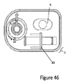
図45〜47に示すように、混合が必要である二連バイアルのシステム4で、使用者には、送達服用を調節する能力がある場合がある。図46に示される最初の位置から図47の最終的な送達量位置まで、服用量選択部48が動かされる。ここで、バイアルホルダー5は、混合と移送を開始するために使用者によって自由に押し込まれることになっている。まず、希釈剤流体は希釈剤バイアルから移されて、粉末状の凍結乾燥された注射可能なバイアルにもたらされる。流体がバイアルから移されるとき、すべての粉が同様に除去されるそのような方法で、流体は粉末のバイアルにもたらされる。希釈剤と粉を混ぜることは、粉末のバイアルで完全に起こる場合があるか、移送器具で完成される場合がある。静的または動的な混合要素は、移送器具に取り込まれる場合があるか、粉末薬または他の注射可能薬物を十分に調合させる移送器具での粉バイアルと希釈剤にもたらされる場合がある。混合は、完了するまで最高数分がかかる場合がある。泡/発泡と剪断応力を最小にするためにできるだけ穏やかな方向で、混合はされる。混合は粉を完全に混ぜられ、小片は存在しないような方法でされる。インライン・フィルタ、弁または他の手段は、小片または空気を除去するために使用される場合がある。指示器は、混合が進歩していることを示すように移送器具の上にある場合がある。
As shown in FIG. 45 to 47, the
図45〜47に示すように、二連のバイアルホルダー5のシステムでは、再構成された溶液は粉末バイアルまたは移送器具6に加えられ、製造者によって定められる溶液の設定された量または使用者による設定は圧力服用室で自動的に変えられる。それから、この設定された容積は、注射装置7へ自動的に移される。注射装置7に薬の最大パーセンテージの移送を促すために、管、パイプ弁と他のどのバイアルと移送器具6の間の流体流路量も最小にされる。
As shown in FIG. 45 to 47, in the
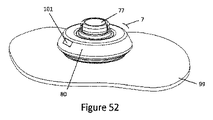
図48〜50に示すように、一旦必須の服用量が注射装置7に送達されると、注射装置7の透明部分80,101は、使用者が完全な混合を確かめるために混合された溶液を見るのを許す。理想的には、使用者は注射装置7の範囲内で全ての薬容積を視認し得る。正しい服用が注射装置7に送達されたことを示すために、指示器(指標)101(相対的な充填ゲージのような)もあり得る。それから、混合の完成と注射装置7への移送は注射装置7の「錠を開けて」、それが移送器具3、6または注射装置ドッキングステーションから取り除かれるのを許す。注射装置7は、ボタン77が上または準備位置にあり、透明部分80,101が注射装置が充填されていることにより、準備状態にあることを使用者に示し得る。
As shown in FIGS. 48-50, once the required doses have been delivered to the
図50に示すように、ねじれるか、移送器具3の注射装置7を取りはずすことによって、使用者は注射装置7を移送器具3から切り離す場合がある。注射装置7の除去の間、接着テープ裏地は自動的に取り除かれ、装置を患者の皮膚に接着するのに用いられる注射装置の底に接着面を露出し得る。あるいは、使用者が付着する前に手で装置を皮膚へ移すために引くタブを、テープ・ライナーは持っている場合がある。
As shown in FIG. 50, the user may disconnect the
図51に示すように、使用者は注射装置7を皮膚99に付ける。皮膚99表面への接着とハンズフリーの操作を可能にするために、注射装置7の底に接着剤がある場合がある。接着剤は、使用者がテープを皮膚にしっかりと付着するのを許すために、注射装置の輪郭を過ぎて広がり得る。あるいは、使用者は注射の間、注射装置7を皮膚99に対して固守する場合がある。
As shown in FIG. 51, the user attaches the
図51〜53に示すように、使用者は安全機構(安全装置)100を取り外して、注射を始めるために、注射装置7のボタン77を押す。一旦注射装置7のボタン77が完全に押されるならば、それはきちんとロックされ、そして、針は患者に完全に挿入され、そして、注射装置7は注射可能な薬を出し始める。注射装置7は、薬の注射が始まったという警報を使用者に出す場合がある。この警報は、視覚的な指示、聞き取れる音、機械の運動または組合せの形であり得る。注射の時間は、数秒から数時間までの範囲で有り得る。注射装置7は、下の位置にあるロックされたボタン77と指示器(指示窓)101が注射装置7が満量よりも少ないことを示すことによって、投与されていることを使用者に指示し得る。注射装置7は、使用者が簡単に、注射装置7の中に残っている薬の量を測定するのを許す透明部分80を望ましくは持っている。
As shown in FIGS. 51 to 53, the user removes the safety mechanism ( safety device ) 100 and presses the
図54に示すように、薬の注射が完了するとき、使用者は警告される。この警報は、視覚の指標、聞き取れる音、機械の運動または組合せの形であり得る。注射装置7は、使用者に、投与が完了したことを、ボタン77がロックアップ位置に動くことで、触覚的に、聞きとれる音とともに示し得、指示器(指示窓)101が注射装置が空であることを示すことによって示し得る。投与の最後に、針は自動的に注射装置7内のロック位置に引き込まれる。
As shown in FIG. 54, the user is alerted when the drug injection is complete. This alert may be in the form of visual indicators, audible sounds, mechanical movements or combinations. The
図54に示すように、皮膚99からの注射装置7の除去と同時に、包帯120は注射装置7から解放されて、皮膚面99で残り得る。皮膚99からの除去と同時に、注射装置7は望ましくはロックアウトされ、そして、針への破壊的でない接近または注射装置7の再利用を妨げる。注射装置7は、完全な服用量が送達されたことを使用者に知らせ得る。この指示は、視覚的な指示、聞き取れる音、機械の運動または組合せの形であり得る。
As shown in FIG. 54, at the same time as the removal of the
本主題の更なる局面に従えば、皮膚の下で注射されるはずである注射器と針で注射を行うとき、針がきちんと皮膚の範囲内で置かれているか、血管の範囲内で不適当に置かれているかを知ることが望ましい。皮内(ID)か、皮下(SC)か、筋肉内(IM)注射を行っている使用者にとって、見える血が注射器に針の上に来るかどうか見るために注射器の範囲内で圧力低下を引き起こすためにプランジャーの上で退くことによって注射器を引くことは一般的である。血が視覚化されるならば、これは針の先端が血管にあることを意味する。皮膚の下で注入のための注射可能な薬は、特に静脈に注射しないために、特に指示する。注射器と針を使う血液吸引は、一般の技術で、十分なトレーニングで誰によってでも行われることができる。しかし、より多くの薬が自動注射装置で示されていて、この種のシステムで手動で吸引する能力は存在しない。注射装置が皮膚に置かれる、そして、一旦針が焼かれるならば、針がきちんと皮膚の範囲内で置かれるか、血管の範囲内で不適当に置かれるかどうかについて、使用者がわかっている方法がない。したがって、自動注射装置内の血液吸引装置と方法の必要が存在する。 According to a further aspect of the present subject matter, when performing an injection with a syringe and needle that is to be injected under the skin, the needle is properly placed within the skin or improperly within the blood vessels. It is desirable to know if it is placed. For users performing an intradermal (ID), subcutaneous (SC), or intramuscular (IM) injection, a pressure drop within the syringe can be seen to see if visible blood comes to the syringe over the needle. It is common to pull the syringe by retracting over the plunger to cause it. If blood is visualized, this means that the needle tip is in a blood vessel. Injectables for injection under the skin are specifically indicated because they are not injected intravenously. Blood suction using a syringe and needle is a common technique and can be done by anyone with sufficient training. However, more drugs have been demonstrated with automatic injection devices and the ability to manually aspirate in this type of system does not exist. The user knows whether the injection device is placed on the skin and, once the needle is burnt, whether the needle is properly placed within the skin or improperly placed within the blood vessels. There is no way. Therefore, there is a need for a blood aspiration device and method within an automatic injection device.
図55〜56に示すように、注射装置7は、ボタン77との働いている関わりの横穴108のある針85を皮膚99に進んでいる隔壁109の範囲内でスライド可能にする場合がある。ボタン77は、針85の近位端161で流体連通にあるボタン頂部103の視認窓160を持っている場合がある。血液159がたまって、使用者によって視認窓(ボタン窓)160で見られるために、ボタン頂部103は、空洞162を含み得る。空洞162は、内腔(針内腔)165を通して針85の近位端161で流体連通を許す中心の穴163を含み得る。空洞162の外壁164は、ボタン頂部103によって作られる。さらに、一部の外壁164は、疎水性フィルタ166を含み得る。この構成の場合、針85の近位端161は、大気圧である。内容物14または血液159が針85の内部の内腔165の上に移動するならば、それは針85の近位端161を出て、空洞162を充填する。空気167の全てが空洞162から移されるまで、空洞162の空気167は疎水性フィルタ166によって簡単に置換され、そして、それは内容物14または血液159で充填される。ここで、内容物14または血液159は疎水性フィルタ166を透過することができず、内容物14または血液159の流れは止まり、使用者によってボタン頂部103の視認窓160で簡単に見られることができる。
As shown in FIGS. 55-56, the
図56に示すように、ボタン77の作動(または押し込み)と同時に、針85とボタン77は、図56で示すように最初の位置または深さへ移動する。この最初の位置または深さでは、横穴108は隔壁109で覆われ、従って、針85の内腔165は投与ポート82の流体チャンネルと連通しない。第1の位置または深さにおいて針先端107が静脈158内にあれば、静脈158内の圧力は内腔165を通って針85の近位端161に向かって血液159を上昇させ、空洞162を血液159で充填し、これはボタン77のボタン頂部103の視認窓160を通して見えるので、注射装置7の針85が静脈158内にあるかどうかを決定する方法を提供する。
At the same time as the
図57に示すように、組織への針挿入は、一般的に4つの段階に分けられることができる。これらは、非接触、境界置換、先端挿入、シャフト挿入を含む。境界置換の間、接触域の組織境界は針先端によって適用される荷重に影響されて反るが、針先端は組織に侵入していない。皮膚の境界は、接触域において、針先端が皮膚に侵入し始める最大の境界置換点まで針の先端に追随する。針先端が皮膚に侵入した後、シャフトが組織に挿入される。先端とシャフトの挿入の後でさえ、接触領域における皮膚の境界表面は元の非接触状態には戻らないが距離xだけ変位したままである。境界変位量xは限定されないが針の直径、針先端の形状、針のシャフトの摩擦、針の挿入速度と物理的な皮膚特性を含むいくつかのパラメータの関数である。接触領域における皮膚の境界変位xは、針を基本とする注射装置において特徴づけられる。それは針が皮膚にいくら侵入するかということに影響があり、従って、実際に針の侵入深さを境界変位xの大きさによって低減できるからである。針先端に先立って接触領域の外で皮膚を押すように、伸ばすまたはプレロードすることによって、もし境界変位xが意図的に誘起されるのであれば、挿入中、針先端またはシャフトによるさらなる境界変位はなく、針先端深さは予想通り規定されるであろう。この意図的な変位は、組織への針の侵入の量が境界変位の変化によって影響を受けないことにおいて有利である。針先端の挿入前に皮膚表面において境界変位を意図的に誘起しなければ、実際の皮膚への針侵入深さは具体的には知られない。図57に示すように、針の長さのいくらかは(上述のパラメータによる)自然に発生する境界変位xによって皮膚の外にあるためである。一方、最大境界変位が接触領域で誘起されると、実際の針侵入深さは針の直径、針の形状、針のシャフトの摩擦、針の挿入速度と皮膚の物理的な特性を含む上述のパラメータの変化によっては変わらないであろう。 As shown in FIG. 57, needle insertion into tissue can generally be divided into four stages. These include non-contact, boundary displacement, tip insertion, shaft insertion. During boundary replacement, the tissue boundaries in the contact area warp under the influence of the load applied by the needle tip, but the needle tip does not penetrate the tissue. The skin boundary follows the needle tip in the contact area up to the point of maximum boundary displacement where the needle tip begins to penetrate the skin. After the needle tip penetrates the skin, the shaft is inserted into the tissue. Even after insertion of the tip and shaft, the boundary surface of the skin in the contact area does not return to its original non-contact state but remains displaced by the distance x. The boundary displacement amount x is a function of several parameters including, but not limited to, needle diameter, needle tip shape, needle shaft friction, needle insertion speed and physical skin characteristics. The boundary displacement x of the skin at the contact area is characterized in needle-based injection devices. This is because how much the needle penetrates the skin, and therefore the depth of penetration of the needle can be actually reduced by the magnitude of the boundary displacement x. If the boundary displacement x is intentionally induced by stretching or preloading to push the skin out of the contact area prior to the needle tip, further boundary displacement by the needle tip or shaft during insertion is No, the needle tip depth will be defined as expected. This deliberate displacement is advantageous in that the amount of needle penetration into the tissue is unaffected by changes in boundary displacement. The actual depth of needle penetration into the skin is not known unless the boundary displacement is intentionally induced on the skin surface before the insertion of the needle tip. As shown in FIG. 57, some of the length of the needle is outside the skin due to the naturally occurring boundary displacement x (due to the parameters described above). On the other hand, if the maximum boundary displacement is induced in the contact area, the actual depth of needle penetration will include the above-mentioned including needle diameter, needle shape, needle shaft friction, needle insertion speed and physical properties of the skin. It will not change due to changes in parameters.
図58に示すように、注射装置7は、投与ポート82において、またはその周りで、または投与ポート82の一部として拡張138を含む下面76のような皮膚境界線置換拡張または構造を備え得る。注射装置7が皮膚99に付けられるとき、拡張138は皮膚99表面に突き出て、この接触領域139で皮膜99の変位を起こす。射出前状態から第1の位置へのボタン77の作動の間、針85は薬の投与を開始するために、注射装置7から投与ポート82および/または拡張138を通って、皮膚99内に進む。上述の理由で、針85が注射装置7から進むとき、針先端107は皮膚99の接触領域139でさらなる境界変位141(すでに故意に拡張138によって誘導されている)を生じさせない。このように、皮膚99の実際の針侵入深さ140は、よりよく特徴づけられ、制御される。
As shown in FIG. 58, the
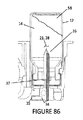
図60に示すように、移送器具3のバイアルアクセス部材21は、移送器具3の内部の流体流路35に連通するために、複数の内腔、例えば多内腔管34を備え得る。バイアルアクセス部材21は、好ましくは、空気または流体がバイアル12に入る1つの入口管36と、空気または流体がバイアル12から出る1つの出口管37を備える。図59に示すように、例えば、バイアルが上下逆にされるときには、バイアルアクセス部材21の内腔開口38は、入口管36の開口が出口管37の開口の上方にあるように指向され得る。この指向は、空気または液体を、上部の入口管36を通してバイアルに導入させ、下部の出口管37を通してバイアルから出させる。さらに、バイアル12の全ての内容物14が出口管37に入ってバイアル12から取り除かれるように、出口管37の開口は逆にされたバイアル12の下端付近に、隔壁19に隣接して位置し得る。バイアル12が移送器具3のバイアルホルダードッキング領域29に搭載されると、バイアルアクセス部材21はバイアル12の内容物14にアクセスすることができる。移送器具3がバイアル12から出口管37まで内容物14を引き込むとき、バイアル12で圧力低下154が生じる。この圧力低下154は、引き込まれる内容物14を空気(置換空気)58が置き換えるようにバイアルアクセス部材21の入口管36の開口を通ってバイアル12に吸い込まれる原因になる。バイアル12の内容物14の量によるいくつかの場合には、バイアル12の液面153は、バイアルアクセス部材21の上方に、そして、具体的には入口管36の開口より上にある場合がある。空気58が入口管36の開口からをバイアル12に吸い込まれると、それは内容物14中に泡155をつくる。浮力は、泡155が既存の空気58とともにバイアル12の頂部に移動する原因になる。いくつかの内容物14において、泡(気泡)155を溶液に導入することは好ましくない。これはより泡立たせ、内容物14内で泡、泡立ち、発泡を引き起こす。
As shown in FIG. 60, the
図61に示すように、拡張可能部材156は、バイアルアクセス部材21の入口管36の開口内で、スライド可能に動かされ得る。拡張可能部材156の外径は、入口管36の開口の内径に密接し得る。拡張可能部材156は、空気58を通過させる内径を有し得る。空気58がバイアル12の圧力低下154により入口管36の開口を通してバイアル12に吸い込まれるとき、空気58は入口管36の開口中でピストンのような拡張可能部材156を最初に押す。拡張可能部材156は十分に長く、入口管36の開口からは外に出ない。拡張可能部材156の端がバイアル内で液面153を上回って、バイアル12の頂部157で止まるまで、拡張可能部材156は入口管36の開口を通ってスライドし続ける。逆にされたバイアル12のふたは、拡張可能部材156を停止させる働きをする。拡張歩合156の先端は、逆にされたバイアル12の頂部に接触した時に内径を通る流れを閉塞しないように、テーパー形状であり得る。バイアル12の中の内容物14の全てがバイアル12から出口管37まで取り出されるまで、空気58は拡張可能部材156の内径中を移動し続ける。上述のように、拡張可能部材156の外径は、入口管36の開口の内径と密着し、この接触面において空気を漏らさない。拡張可能部材156は、バイアル12に空気58が入って泡(気泡)155を引き起こすことをがないことを確実にする。
As shown in FIG. 61, the
図62に示すように、圧力室59は、内容物14と空気58を室内にもたらす入口ポート168とともに構成され得る。さらに、圧力室59は圧力室59から内容物14や空気58を噴出するのに出口ポート64を有するように構成され得る。これらのポート168,64は、圧力室59の中に導入する、および/または、圧力室59から放出される内容物14と空気58の流れの制御を助けるために、圧力室59の中心からずらして配置され得る。前述のように、圧力室59の出口ポート64は入口ポートの下方に配置され、圧力室59からの内容物14の放出の間、まず全ての内容物14が放出されて、その後残った空気58が最後に放出される。圧力室59内の全ての空気は圧力室59の頂部に向かって、上向きに方向づけられる。さらに、図62に示すように、圧力室59から空気を取り除く前に圧力室59内の全ての液体の内容物14を出口ポート64に出させて圧力室59から取り出すために、出口ポートの外形は非円形の形状であり得る。さらに、図62に示すように、出口ポート64の部分170は、圧力室59の表面171の下に置かれ得る。これは、さらに全ての液体の内容物を圧力室59から出口ポート64に入れて、圧力室59から空気58が取り除かれるのに先立って圧力室59から取り除くために、トラップとして働き得る。
As shown in FIG. 62, the
図63に示すように、バイアルアクセス部材21を使用して内容物14がバイアル12から取り除かれるとき、液面153が出口管37の開口の頂上よりも落ち込むまで、内容物14のみが出口管37の開口を通って取り除かれる。このとき、内容物14と空気58の混合物は取り除かれる。図63に示すように、バイアルアクセス部材21は、開口の高さを小さくし、開口の幅を大きくして、バイアル12のより多くの液体の内容物14を出口管37に入れて、バイアル12から空気を除去する前に除去するために、さらに非円形の形状に構成された出口管37の開口を有し得る。
As shown in FIG. 63, when the
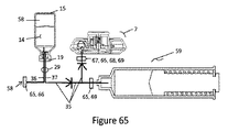
図64と図65に示すように、バイアル15と注射装置7との間の流体流路35における疎水フィルタ68と親水フィルタ69の組み合わせは、好ましくは、移送過程中に内容物14のろ過と空気58の除去をさせ得る。このフィルタは、別個の要素であるか、1つの要素に組み合わされている場合がある。それぞれのフィルタは、限定ではないが混合セルロース・エステル(MCE)、重合ビニリデン・ジフルオリド(PVDF)、ポリテトラフルオロエチレン(PTFE)、ナイロンとポリエーテルサルホン(PES)を含む異なる材料で構成され得る。それぞれのフィルタは、孔径が0.22〜3μmの範囲であり得る。それぞれのフィルタは疎水性または親水性にするためにコーティングされている。
As shown in FIG. 64 and FIG. 65, the combination of sparse water filter 68 and the parent water filter 69 in the
皮膚の下で注入されるはずの注射をするとき、一般的な反応は注入領域の膨張である。特に、注入量が高い、および/または、注入速度が速い皮下場所で、この反応が言われる。注入が、注射器と針と投与セットによってなされているのであれば、注入領域の膨張は注射装置に何等影響を与えない。しかしながら、注入の間、体に付着され着けられる自動注射装置においてより多くの薬が用いられており、領域の膨張は、自動注射装置を確実に体の上に保つにあたって困難を提示している。特に、注射装置の接着剤が適切に設計されなければ、皮膚面に注入された溶液によって形成されるかたまりまたはふくらみが、自動注射装置が注入領域から取り除く場合がある。従って、装置の患者への接着を危うくすることなく注射領域でふくらむようにする、適切に設計された接着剤を有する自動注射装置の必要が存在する。 When making an injection that should be injected under the skin, a common reaction is swelling of the injection area. This reaction is said to occur especially in subcutaneous sites where the injection volume is high and / or the injection rate is high. If the injection is made with a syringe, needle and dosing set, the expansion of the injection area has no effect on the injection device. However, more medication is used in auto-injection devices that are attached to and worn on the body during infusion, and the expansion of the area presents difficulties in ensuring that the auto-injection device remains on the body. In particular, if the adhesive of the injection device is not properly designed, the lumps or bulges formed by the injected solution on the skin surface may be removed by the automatic injection device from the injection area. Therefore, there is a need for an auto-injection device with a properly designed adhesive that allows the device to bulge in the injection area without compromising adherence to the patient.
図66に示すように、注射装置7を皮膚99に接着させることに関して、2つの境界面がある。第1は接着剤/装置境界面173であり、第2は接着剤/皮膚境界面174である。
As shown in FIG. 66, there are two interfaces for adhering the
図67に示すように、接着剤88は少なくとも2つの領域を有する注射装置7に構成され得る。第1の領域175は、接着剤88と注射装置7との間で機械的又は科学的な手段を用いる永久接着剤を含み得、好ましくは注射装置7の周辺内に配置され得る。第2の領域176は、注射装置7から剥がすまたは取り外すことができるように、好ましくは領域1の外側に隣接して(例えば放射状に外向きに)構成され得る。
As shown in FIG. 67, the adhesive 88 may be configured on the
図68に示すように、接着剤88が注射装置7の下面(底)76に完全に付けられるならば、この接着剤/皮膚境界面174は接着剤/装置境界面173より弱いので、組織のふくらみ177の間、接着剤/皮膚境界面174の接着剤は皮膚99からはがれ始めるであろう。このことは図68に示す膨らんだ表面に示されている。これは、注射装置7が皮膚99の表面からはがれて患者から落ちることになる。
If the adhesive 88 is completely applied to the lower surface ( bottom ) 76 of the
図67と図69に示すように、図68に示すように完全に永久的に接着剤88を注射装置7の下面(底)76に取り付ける代わりに、接着剤88が注射装置7の上述の領域175,176において構成され得る。この構成では、組織のふくらみ177が起きている間、第2の領域176の接着剤88は注射装置7からはがれ、そして接着剤/皮膚境界面174においてしっかりと皮膚99に接着される。これは、接着剤/皮膚境界面174から接着剤/装置境界面173への皮端部178の移送をさせ、接着剤/皮膚境界面において、効果的にゆがみを緩和する。接着剤/装置境界面173は、より強く、注射装置7が皮膚99の表面から離れることを防ぐように設計され得る。
As shown in FIGS. 67 and 69, instead of completely and permanently attaching the adhesive 88 to the lower surface ( bottom ) 76 of the
自動注射装置を用いて自己注射をする時、使用者を針差し事故から保護することは、装置に対する有益な要求である。一般的に、針は使用の前後に装置の範囲内に格納される。そして、使用者が針にアクセスするのを防ぐ。しかし、注射の間、針は装置の外側に延ばされる。自動注射装置を身に付けている状態で、注射の間、不注意に使用者が転ぶと、針は使用者にとって針差しの危険の可能性を生じる。従って、自動注射装置には、注射の間にもし装置が皮膚から外れたら自動的に針を引き込む皮膚除去センサの必要が存在する。 When self-injecting with an automatic injection device, protecting the user from accidental needle insertions is a beneficial requirement for the device. Generally, the needle is stored within the device before and after use. It also prevents the user from accessing the needle. However, during injection, the needle is extended outside the device. If the user inadvertently rolls during the injection while wearing the automatic injection device, the needle presents a risk of needle insertion for the user. Therefore, there is a need for an automatic injection device with a skin removal sensor that automatically retracts the needle during injection if the device disengages from the skin.
図70〜72に示すように、皮膚除去センサ179は、ボタン77の柔軟なラッチ181に操作可能に係合し、注射装置7の下部ハウジング180内でスライド可能である。図71に示すように、注射装置7が皮膚99の表面に取り付けられている時、皮膚除去センサ179は注射装置7の第1または上の位置182にあるよう強制される。ボタン77が射出状態または第2の位置または投与位置に(針85を露出して)作動されると、柔軟なラッチ181は皮膚除去センサ179によって、ラッチ板183の下のロック位置187にあるように強制される。ラッチ板183は、ボタン77をラッチ板表面84に、ボタン77が射出状態に押された状態で、または投与終わるまで投与位置で保持する。投与の終わりに、ラッチ板183はボタン77上のラッチ板表面184から離され、ボタン77と針85は射出後位置に引き込まれ、針は注射装置7内に収容される。図72に示すように、注射装置7が注射の間に皮膚99の表面から取り除かれた場合には、皮膚除去センサ179が注射装置7の外の第2の位置または下位置185まで延びる。これは、柔軟なラッチ181にロック解除位置へばねで戻らせてラッチ板183から離れさせる。これはまたボタン77と針85を発射後位置に引き込ませ、針85は注射装置7内に収容されている。
As shown in FIG. 70 to 72, the skin is removed
注射器と針で自己注射を実行するとき、使用者には一時的に注射領域で激痛または刺激により注射を止めるか、中断する必要があり得る。注射領域への注射可能な薬の流れのこの中断は、注射器のプランジャーロッドへの圧力を取り除くことによって達成され、注射可能な薬の流体の大量投与を許し、周囲の組織に拡散するためのより長い時間を許し、局所的な圧力を低減し、それに伴う痛みと炎症を低減することができる。しかしながら、より多くの薬が自動注射装置で示されていて、手動でこの種の自動のシステムを中断することができない。自動注射装置が皮膚に置かれ、一旦カニューレが持ち出されると、使用者が、注射領域の痛みまたは刺激によって注射を休止させる方法がない。したがって、使用者が自動注射システムを休止させられる必要が存在する。 When performing self-injection with a syringe and needle, the user may need to temporarily stop or discontinue the injection due to severe pain or irritation at the injection area. This interruption of the flow of injectable drug to the injection area is achieved by removing the pressure on the plunger rod of the syringe, allowing a large dose of fluid of the injectable drug to diffuse into the surrounding tissues. It allows longer times, reduces local pressure, and reduces associated pain and inflammation. However, more drugs have been shown in automatic injection devices, and it is not possible to manually interrupt this type of automatic system. Once the automatic injection device is placed on the skin and the cannula is removed, there is no way for the user to pause the injection due to pain or irritation in the injection area. Therefore, there is a need for the user to be able to deactivate the automatic injection system.
図73〜74に示すように、ボタン77の作動と同時に、針85とボタン77は、図73で示すように第1の位置または深さへ移動する。この第1の位置または深さでは、横穴108は隔壁109によって覆われている。したがって針85の内腔165は投与ポート82の流体チャンネル86と連通していない。ボタン77は、流体チャンネル86を通って針85の横穴108にそして皮膚99に注射可能な内容物14が流れることを防ぐために、意図的に第1の位置または深さに保持されている。図74に示すように、ボタン77が解放されると、針85とボタン77は第2の位置または投与位置に戻り、横孔108は流体チャンネル86に露出され、注射可能な内容物14は注射の最後まで、流体チャンネル86から針85の横穴108にそして皮膚99に流れされられる。ボタン77を第1の位置または深さに押すこの動作は、注射全体の間、必要な回数だけ実行され得る。
73-74, upon actuation of
図75〜76に示すように、ボタン77の力(作動力、荷重)186は、ボタン77と針85の射出前位置から射出状態または投与位置まで変位の開始を要求されたボタン77に適用される荷重の移行である。この移行荷重が応じられるまで、ボタン77への力186は直接注射装置7に移行される。特に、この力186は接着剤/皮膚境界面174および/または接着剤/装置境界面173に移行され得、注射装置7を作動させる前に、結果として注射装置7の皮膚99の表面へのよりよい確実性をもたらす。
As shown in FIGS. 75 to 76, the force ( operating force , load) 186 of the
図77に示すように、移送器具3の指示窓172は、内容物14の移送および/または混合が進行していることを示すために存在し得る。指示窓172は、移送器具3の基台中に構成され得、移送装置3内で圧力室56のプランジャー93の動きを追跡し得る。指示窓172は、スケールまたはプランジャー93の動きを追跡する他の方法で構成され得る。あるいは、プランジャー93は、指示窓172内で動きを追跡することが容易にするよう異なる色で構成され得る。指示窓172とプランジャー93の組み合わせは、バイアル12からの内容物14の引き込みと圧力室56の充填の進捗を提供し得る。指示窓172とプランジャー93との組合せは、内容物14の圧力室56から注射装置7への移送の進捗をも提供し得る。
As shown in FIG. 77, the
図78〜79に示すように、弓状の拡張可能部材78は、長さにおいて弓形状に配置され、および/または、好ましくは延ばされている。図示した実施形態においては、弓型は、例えばより厚いまたは重い壁の厚い領域126のような強さが少ない領域を与えることによって誘起される。その領域では拡張可能部材はより少なく反り、拡張された弓型を形成することになる。重い壁の厚い領域126は、膨張の間、拡張可能部材78を弓状にさせる、いかなる形状にも構成され得る。重い壁の厚い領域126のより好ましい構造は、その厚みまたは拡張可能部材78の壁上の周方向における取付具150を最小化すること、そして、放射方向の厚みまたは拡張可能部材78から離れる突起151を最小限にすることである。これは、拡張可能部材78が弓形に膨張することを促すために役立つが、膨張のために重い壁の厚い領域126によって影響されない周囲の材料の量を最小にする。限定ではないがT字型の構成は、拡張可能部材78が弓状に膨張することを助けるために、放射状の突起152の端部に構成され得る。
As shown in FIG. 78-79, arcuate
図80に示すように、圧力室56の容積は、追加の空気58がバイアル15から圧力室56内に引き込まれるために、バイアル15中の全流体の体積より大きく設定され得る。この追加の空気は、全ての内容物14がバイアル15から取り除かれ、バイアル15と圧力室56の間の流体流路35中の残りの内容物14の除去と清掃を確認するために役立ち得る。さらに、圧力室56から注射装置7への内容物14の移送の間、圧力室56と注射装置7の間の流体流路35の中の残留する内容物14の除去または清掃に、さらなる空気が役立つ場合がある。
As shown in FIG. 80, the volume of the
図81に示すように、移送器具3は、細長いバイアルアクセス部材21を含み得るバイアルホルダードッキング領域29を備える。バイアルホルダードッキング領域29は、バイアルアクセス保護部136を含み得る。バイアルアクセス保護部136は、バイアル12またはバイアルホルダーの挿入に先立って、バイアルアクセス部材21を覆ってバイアルアクセス部材が不注意に使用者に刺さることを防止するために、バイアルホルダードッキング領域29において、バイアルアクセス部材21の上方の第1の位置に、ロック指137によってロックされ保持されている。バイアル12またはバイアルホルダーがバイアルホルダードッキング領域29に挿入されると、バイアル12またはバイアルホルダーはロック指137を変位させて、バイアルアクセス保護部136のロックを解除する。ロックが解除されると、バイアルアクセス保護部136は、バイアルホルダードッキング領域29内でバイアル12またはバイアルホルダーとともにスライドして動くことが可能である。
As shown in FIG. 81, the
図82に示すように、流れ絞り55が流体流路35内で制御および/または移送時間を遅らせるために、および/または混合時間を増加させるために、使用され得る。小さい内腔管は、流体流路35のいかなる点においても流れを制限し、混合/移送時間を1時間以上に増加させるために使用され得る。制御する、および/または、移送時間を送らせる、および/または、第2の圧力室42と注射装置7との間で混同時間を増加させる、1つの方法は、多数内腔の流体流路142を第2の圧力室42と注射装置7との間で使用することである。流体流路142のそれぞれの内腔143,144は、第2の圧力室42において、好ましくはピストンの移動距離だけ間隔を空けて、内径147,148は第2の圧力室42内の圧力に基づいて内腔143,144を通過する特定の流速を与える大きさであり、特定の位置145,146に取り付けられている。初めに、第2の圧力室のピストン46が、第2の圧力室42内で前進を開始する時、流体の内容物14は、全内腔143,144を通して流体流路142内に、注射装置7に向かって投与される。ピストンが内腔143と第2の圧力室42の間の取付点145を通過すると、その内腔143を通過する流体の流れは、停止し、内容物14は、残りの内腔144を流れるように強制される。多数の内腔と取付点は、圧力室に沿って配置され得る。内容物14の流れから利用可能な最終の内腔144は、内径が非常に小さくされるであろう。従って流速は非常に遅く、内容物14を第2の圧力室42から注射装置7に移送する時間は増大するであろう。この移送の遅れは、混合時間を増加させる。
As shown in FIG. 82, a
図83に示すように、安全ピンや安全スリーブのような安全機構(安全装置)100は、射出(注射)の準備のために注射装置7を解放するために、いかなる方向への解放においても、注射装置7から取り外させるように構成され得る。
As shown in FIG. 83, the safety mechanism such as a safety pin or safety sleeves (safety device) 100, in order to release the
図84に示すように、注射装置7のボタン77が完全に押されると、流体チャンネル86と皮膚99の間の流体連通を可能にする横穴108のある針85を、注射装置7は含む。この開始は、注射可能な内容物14を投与する。針85の内腔165は、注射装置7から投与する速度を制御する際に重要である。管内の流体流れについてのハーゲン−ポアズイユ方程式を参照して、管を通る流速は管の半径の4乗に比例する。従って、特に内腔165が小さくなる場合には、針85の内径を少し変えることで、針85を通過する流れは大きく変わる。注射装置7内の針85は様々な壁の厚みにおいて、21Gから34G(Stubs Iron Wire Gauge System)の範囲であり得る。この範囲は、いかなる与えられた針の大きさついても、針の内腔165の内径には製造によるばらつきと許容があり、内腔165の内径の0.021”から0.003”の範囲に一致する。これは針サイズに基づいており、内径は±0.00075”程度のばらつきである。どのような針サイズであっても内腔165の内径の範囲を限定し、その結果流れのばらつきを限定するために、針85は注射装置7に組付けられる前に修正され得る。この修正は、針を長さの一部分以上、新しい定められた効果的な内腔165の内径に、円形から非円形に、針を折るか、平らにするか、転がすことを含み得る。これは、注射装置7から特定の送達速度の制御を可能にする利点がある。
As shown in FIG. 84, the
図85〜86に示すように、バイアルアクセス部材21の内腔開口38は、加圧された空気または液体を、上部の入口管36を通って導入させ、下部の出口管37を通ってバイアルの内容物14を出力するように指向され得る。さらに、出口管37の開口は、バイアル12の全内容物14が出口管37に入ってバイアル12から取り出されるように、逆さにされたバイアル12の底近傍に、隔壁19に隣接して配置され得る。バイアル12からの内容物14の取り出しの好ましい順序は、まず、バイアル12中の全ての内容物14、その後、バイアル12からの空気58である。これは現在の実施の形態において、移送器具3の方向が、図85〜86のように指向されている時、達成されている。バイアル12内のバイアルアクセス部材21の形状に基づいて、全ての内容物23その後空気58の除去というこの順序は、移送器具3の角度が水平から±45°まで達成される。この角度を超えると、空気58が、内容物14のバイアル12からの除去の間に導入されることを引き起こす。センサ(角度センサ)149は、移送器具3の角度を感知するために、バイアルアクセス部材21の中または周囲に配置される。それぞれまたはいずれもの内腔開口38、および/または、それぞれまたはいずれもの入口管36と出口管37との間に直接、連通を有し得る。図85に示す現在の実施形態では、移送器具3が45°よりも小さい角度にあると、センサ149が出口管37と流体流路35との間で流体連通させる。図86に示すように、移送器具3が45°よりも大きく傾いていれば、センサ149は、出口管37と流体流路35との間の流体連通を遮断するために、新しい位置に回転または移動する。
As shown in FIG. 85-86, the inner腔開
図87に示すように、混合を実行しないが、内容物14を単一のバイアル12から注射装置7に移す、単一バイアルシステム内の別の移送器具3が提供される。この別の移送器具3は、内容物14を、バイアル12から注射装置7に向けるために、バイアル12と、可変容積の圧力室56と、流体流路35とを含む。バイアルアクセス部材21の入口管36は、流体流路35を有する可変容積の圧力室56に接続されている。バイアルアクセス部材21の出口管37は、流体流路の圧力室56を通って注射装置7に接続されている。
As shown in FIG. 87, but not perform mixing, transfer the
図87に示すように、使用者による移送器具3へのバイアル12の完全な挿入は、バイアル12の隔壁19を通して、バイアルアクセス部材21の導入がバイアル12の内容物14にアクセスすることを引き起こす。これも、圧力室のトリガー49の解放を誘発する。引込位置にあるプランジャー60と、圧力室56は、空気135で満たされている。トリガー49は、プランジャー60を、投与ばね63に接続されている圧力室56内で解放する。投与ばね63はプランジャー60を前進させ、入口管36を通って圧力室56から単一のバイアル12内に空気135を置換させる。バイアル12に入る空気135は、出口管37を通って、内容物14をバイアル12の外部に注射装置7内に置換する。これは、すべての内容物14がバイアル12の外へ、注射装置7の中に置き換えられるまで続く。逆止弁40は、内容物14がバイアル12に戻ることを防ぐために、または、内容物14が圧力室56に戻ることを防ぐために用いられ得る。
As shown in FIG. 87, the complete insertion of the
本主題は、説明のためにのみ、制限ためでなく、特定の具体例に関して記述された。
主題の範囲は、図示した実施の形態またはその均等物だけに限られず、いくつかはこの説明と他を読むとすぐに明らかであり、他は若干の研究および/または発展の後明らかである、変形された構成と使用においてより広い実施の形態の適用を有すると理解されるべきである。
The present subject matter has been described with respect to particular embodiments, for purposes of explanation only, and not limitation.
The scope of the subject matter is not limited to the illustrated embodiments or equivalents thereof, some will be apparent upon reading this description and others, and others will be apparent after some research and / or development, It should be understood that it has application of broader embodiments in modified construction and use.
Claims (24)
弾性体によって形成され、前記ハウジング内に収容され、近位端と、末端と、前記近位端と前記末端との間に延びる壁を含む、弓状に拡張可能な空気袋と、
投与前位置と投与位置との間において前記ハウジング内の中央部で可動であり、前記投与前位置において前記空気袋と流体連通ではなく、前記投与位置において前記空気袋と流体連通である注射カニューレと、
前記ハウジング内において前記空気袋の前記近位端に取り付けられ、流体入口ポートと、加圧下で前記空気袋に液体を導入するために前記流体入口ポートと前記空気袋の間で連通する流体流路を有するマニホールドとを備え、
前記空気袋の前記末端は、前記ハウジング内で移動可能であり、液体が加圧下で前記空気袋を拡張するために導入されるとき、前記空気袋は、前記近位端と前記末端との間で拡張され、前記空気袋の前記末端は弓状の通路に沿って前記空気袋の前記近位端から遠ざかるように少なくとも部分的に前記ハウジングの中心部分の周りを移動し、
前記空気袋が弓状に拡張されたとき、前記空気袋の壁の弾性力が前記空気袋から前記注射カニューレを通って液体を排出するように圧力を与え、前記空気袋から前記注射カニューレを通って液体が流れるとき、前記空気袋の壁の前記弾性力によって前記空気袋の前記末端は前記弓状の通路に沿って前記近位端に向かって動く、注射装置。 Housing,
An arcuately expandable bladder formed by an elastic body and contained within the housing, the proximal end, a distal end, and a wall extending between the proximal end and the distal end.
An injection cannula that is movable centrally within the housing between pre-administration positions and in fluid communication with the bladder at the pre-administration position, but not in fluid communication with the bladder at the pre-administration position. ,
A fluid inlet port mounted in the housing at the proximal end of the bladder and in fluid communication with the fluid inlet port for introducing liquid into the bladder under pressure. And a manifold having
The end of the bladder is moveable within the housing such that the bladder is between the proximal end and the end when liquid is introduced under pressure to expand the bladder. And the distal end of the bladder moves at least partially around a central portion of the housing along an arcuate passage away from the proximal end of the bladder,
When the bladder is arcuately expanded, the elastic force of the wall of the bladder exerts pressure to expel liquid from the bladder through the injection cannula and through the bladder through the injection cannula. The injection device, wherein the distal end of the bladder moves toward the proximal end along the arcuate passage due to the elastic force of the bladder wall when liquid flows.
前記隔壁は、前記カニューレを使用まで無菌に保つように構成されている、請求項1に記載の注射装置。 Equipped with a partition,
The injection device of claim 1, wherein the septum is configured to keep the cannula sterile until use.
請求項1から請求項23までのいずれか1項に記載の注射装置とを含む、対象に注射可能な液剤の移送と投与のための薬物輸送システム。 A transfer device,
A drug delivery system for delivering and administering a liquid agent injectable to a subject, comprising the injection device according to any one of claims 1 to 23.
Applications Claiming Priority (5)
| Application Number | Priority Date | Filing Date | Title |
|---|---|---|---|
| US201361836266P | 2013-06-18 | 2013-06-18 | |
| US61/836,266 | 2013-06-18 | ||
| US201461979816P | 2014-04-15 | 2014-04-15 | |
| US61/979,816 | 2014-04-15 | ||
| PCT/US2014/042627 WO2014204894A2 (en) | 2013-06-18 | 2014-06-17 | Vial transfer and injection apparatus and method |
Related Child Applications (1)
| Application Number | Title | Priority Date | Filing Date |
|---|---|---|---|
| JP2020070229A Division JP7053709B2 (en) | 2013-06-18 | 2020-04-09 | Vial transfer and injection equipment and methods |
Publications (3)
| Publication Number | Publication Date |
|---|---|
| JP2016524513A JP2016524513A (en) | 2016-08-18 |
| JP2016524513A5 JP2016524513A5 (en) | 2017-07-20 |
| JP6691041B2 true JP6691041B2 (en) | 2020-04-28 |
Family
ID=51162958
Family Applications (4)
| Application Number | Title | Priority Date | Filing Date |
|---|---|---|---|
| JP2016521495A Active JP6691041B2 (en) | 2013-06-18 | 2014-06-17 | Vial transfer and injection devices and methods |
| JP2020070229A Active JP7053709B2 (en) | 2013-06-18 | 2020-04-09 | Vial transfer and injection equipment and methods |
| JP2022058175A Active JP7389162B2 (en) | 2013-06-18 | 2022-03-31 | Vial transfer and injection equipment and methods |
| JP2023195201A Pending JP2024020437A (en) | 2013-06-18 | 2023-11-16 | Vial transfer and injection equipment and methods |
Family Applications After (3)
| Application Number | Title | Priority Date | Filing Date |
|---|---|---|---|
| JP2020070229A Active JP7053709B2 (en) | 2013-06-18 | 2020-04-09 | Vial transfer and injection equipment and methods |
| JP2022058175A Active JP7389162B2 (en) | 2013-06-18 | 2022-03-31 | Vial transfer and injection equipment and methods |
| JP2023195201A Pending JP2024020437A (en) | 2013-06-18 | 2023-11-16 | Vial transfer and injection equipment and methods |
Country Status (10)
| Country | Link |
|---|---|
| US (3) | US9925333B2 (en) |
| EP (3) | EP4144390A3 (en) |
| JP (4) | JP6691041B2 (en) |
| CN (2) | CN111803762B (en) |
| AU (4) | AU2014281715B2 (en) |
| CA (1) | CA2910081A1 (en) |
| DK (2) | DK3682920T3 (en) |
| ES (2) | ES2928322T3 (en) |
| HU (2) | HUE043627T2 (en) |
| WO (1) | WO2014204894A2 (en) |
Cited By (1)
| Publication number | Priority date | Publication date | Assignee | Title |
|---|---|---|---|---|
| US11771841B2 (en) | 2020-12-23 | 2023-10-03 | Tolmar International Limited | Systems and methods for mixing syringe valve assemblies |
Families Citing this family (59)
| Publication number | Priority date | Publication date | Assignee | Title |
|---|---|---|---|---|
| DE602005023458D1 (en) | 2005-09-12 | 2010-10-21 | Unomedical As | A delivery system for an infusion set having first and second spring units |
| US9415159B2 (en) | 2010-03-30 | 2016-08-16 | Unomedical A/S | Medical device |
| US10194938B2 (en) | 2011-03-14 | 2019-02-05 | UnoMedical, AS | Inserter system with transport protection |
| CN103957962B (en) | 2011-10-05 | 2017-07-07 | 犹诺医药有限公司 | Insert for inserting multiple percutaneous parts simultaneously |
| EP2583715A1 (en) | 2011-10-19 | 2013-04-24 | Unomedical A/S | Infusion tube system and method for manufacture |
| US20150217058A1 (en) | 2012-09-24 | 2015-08-06 | Enable Injections, Llc | Medical vial and injector assemblies and methods of use |
| CA2910081A1 (en) | 2013-06-18 | 2014-12-24 | Enable Injections, Llc | Vial transfer and injection apparatus and method |
| US10994871B2 (en) * | 2013-07-03 | 2021-05-04 | Deka Products Limited Partnership | Apparatus, system and method for fluid delivery |
| US11077965B2 (en) * | 2013-07-03 | 2021-08-03 | Deka Products Limited Partnership | Apparatus, system and method for fluid delivery |
| EP3037119A1 (en) * | 2014-12-23 | 2016-06-29 | Hipra Scientific, S.L.U. | Device for administering medicinal products |
| EP3236882B1 (en) | 2014-12-23 | 2020-02-05 | Automed Pty Ltd | Delivery apparatus, system and associated methods |
| WO2016154413A1 (en) * | 2015-03-26 | 2016-09-29 | Enable Injections, Inc | Pressurized gas powered medicament transfer and re-suspension apparatus and method |
| WO2017004345A1 (en) | 2015-06-30 | 2017-01-05 | Kaleo, Inc. | Auto-injectors for administration of a medicament within a prefilled syringe |
| WO2017014847A1 (en) | 2015-07-17 | 2017-01-26 | Enable Injections, Inc. | Fluid flow control valve and flow control devices and methods employing same |
| DE102015218723A1 (en) * | 2015-09-29 | 2017-03-30 | Transcoject Gmbh | filling aid |
| EP3400051A4 (en) * | 2016-01-04 | 2019-08-07 | Insulet Corporation | Filling assist mechanisms and keyed interfaces for drug delivery devices |
| EP3405230A1 (en) | 2016-01-19 | 2018-11-28 | Unomedical A/S | Cannula and infusion devices |
| US10660823B2 (en) * | 2016-01-29 | 2020-05-26 | Credence Medsystems, Inc. | System and method for injection component preparation |
| WO2017181325A1 (en) * | 2016-04-18 | 2017-10-26 | Medtrum Technologies Inc. | Multi-mode power supply system for a portable infusion device |
| TWI746569B (en) | 2016-06-08 | 2021-11-21 | 瑞士商瑞健醫療股份有限公司 | Dosiergerat, injektionsvorrichtung und verwendung |
| US10850873B2 (en) * | 2016-08-04 | 2020-12-01 | Vanrx Pharmasystems Inc. | Apparatus and method for asepticaly filling pharmaceutical containers with a pharmaceutical fluid using rotary stage |
| CN106110445B (en) * | 2016-08-12 | 2019-12-03 | 上海移宇科技股份有限公司 | A kind of infusion system of portable medication infusion device |
| WO2018096149A1 (en) | 2016-11-28 | 2018-05-31 | Idorsia Pharmaceuticals Ltd | Device for dispensing a substance |
| US20180147357A1 (en) * | 2016-11-29 | 2018-05-31 | Amir Marashi | Delivery method for preparation and administration of pharmaceutical compositions |
| WO2018119218A1 (en) | 2016-12-23 | 2018-06-28 | Kaleo, Inc. | Medicament delivery device and methods for delivering drugs to infants and children |
| EP3354303B1 (en) * | 2017-01-31 | 2020-01-08 | Société Industrielle de Sonceboz S.A. | Drug delivery system |
| KR20190115004A (en) | 2017-02-20 | 2019-10-10 | 아벤트, 인크. | Shaft for injection assembly |
| EP3582828B1 (en) | 2017-02-20 | 2022-08-17 | Avent, Inc. | Bladder for an infusion assembly |
| WO2018165143A1 (en) | 2017-03-06 | 2018-09-13 | Amgen Inc. | Drug delivery device with activation prevention feature |
| WO2018165588A1 (en) | 2017-03-10 | 2018-09-13 | Enable Injections, Inc. | Reconstitution device, system and method |
| KR101811846B1 (en) * | 2017-03-15 | 2017-12-22 | 김휘화 | Safety improved semi-automatic syringe |
| WO2018218082A1 (en) * | 2017-05-25 | 2018-11-29 | Enable Injections, Inc. | Medical fluid transfer and injection apparatus and method with compliance monitoring |
| CN117562807A (en) | 2017-06-15 | 2024-02-20 | 因内博注射剂公司 | Handheld fluid transfer device and system |
| CN111107826A (en) * | 2017-07-20 | 2020-05-05 | 詹森生物科技公司 | Medicine mixing device |
| CA3073835A1 (en) | 2017-08-30 | 2019-03-07 | Pirouette Medical LLC | Compact auto-injector |
| US10814062B2 (en) * | 2017-08-31 | 2020-10-27 | Becton, Dickinson And Company | Reservoir with low volume sensor |
| WO2019058947A1 (en) | 2017-09-19 | 2019-03-28 | 株式会社村田製作所 | Filtration device and filtration method |
| JP6927314B2 (en) | 2017-09-25 | 2021-08-25 | 株式会社村田製作所 | Filtration device |
| US10441714B2 (en) | 2017-10-05 | 2019-10-15 | Pirouette Medical LLC | Protective case for an auto-injector |
| US11413393B2 (en) * | 2017-10-12 | 2022-08-16 | Enable Injections, Inc. | Injection device with adhesive assembly |
| EP3697367B1 (en) * | 2017-10-16 | 2024-04-10 | Enable Injections, Inc. | Pressurized gas powered liquid transfer device and system |
| WO2019217845A1 (en) * | 2018-05-11 | 2019-11-14 | Bristol-Myers Squibb Company | Serially-connectable drug modules for combinatorial drug delivery device |
| US11458250B2 (en) | 2018-05-31 | 2022-10-04 | Insulet Corporation | System and techniques for drug reservoir volume detection |
| US11357909B2 (en) | 2018-10-05 | 2022-06-14 | Eitan Medical Ltd. | Triggering sequence |
| USD1015564S1 (en) * | 2018-10-11 | 2024-02-20 | Human Brain Wave S.R.L. | Medical vessel for a specimen |
| JP7460623B2 (en) * | 2018-12-03 | 2024-04-02 | サーテックス メディカル インコーポレイテッド | Device for delivering radioembolization microspheres |
| WO2020115108A1 (en) | 2018-12-06 | 2020-06-11 | Sørlandet Sykehus Hf | Egfr inhibitors and their use in the treatment of neuroathic pain |
| WO2020118165A1 (en) | 2018-12-07 | 2020-06-11 | Jazz Pharmaceuticals Ireland Limited | Subcutaneous delivery of high concentration formulations |
| CN113613616A (en) | 2019-01-04 | 2021-11-05 | 因内博注射剂公司 | Medical fluid injection device and method with detachable patch and monitoring |
| US11109800B2 (en) | 2019-01-04 | 2021-09-07 | Enable Injections, Inc. | Medical fluid injection apparatus and method with detachable patch and monitoring |
| AU2020279722A1 (en) | 2019-05-20 | 2021-11-18 | Unomedical A/S | Rotatable infusion device and methods thereof |
| JP2022543523A (en) | 2019-08-09 | 2022-10-13 | カレオ,インコーポレイテッド | Device and method for delivery of substances in pre-filled syringes |
| US20220362106A1 (en) | 2019-09-30 | 2022-11-17 | Becton, Dickinson And Company | Medicament filling system |
| US11957542B2 (en) | 2020-04-30 | 2024-04-16 | Automed Patent Holdco, Llc | Sensing complete injection for animal injection device |
| IT202000009751A1 (en) * | 2020-05-04 | 2021-11-04 | Biovalley Group S P A | FLUID GROUP AND RELATED EQUIPMENT FOR THE PREPARATION OF DRUGS |
| AU2021335221A1 (en) * | 2020-08-31 | 2023-03-02 | Curium Us Llc | Container closure including vortex-generating feature |
| EP4351681A1 (en) * | 2021-06-11 | 2024-04-17 | Becton Dickinson and Company | Apparatus for filling a fluid delivery device |
| GB202108472D0 (en) * | 2021-06-14 | 2021-07-28 | Teva Branded Pharmaceutical Products R&D Inc | Medical device packaging |
| JP2023172997A (en) | 2022-05-25 | 2023-12-07 | トヨタ紡織株式会社 | Method of producing catalyst, catalyst, and fuel cell |
Family Cites Families (258)
| Publication number | Priority date | Publication date | Assignee | Title |
|---|---|---|---|---|
| US605693A (en) | 1898-06-14 | John l | ||
| US2584397A (en) | 1945-10-03 | 1952-02-05 | Louis K Pitman | Apparatus for transferring liquid from one container to another |
| US2737948A (en) | 1954-08-23 | 1956-03-13 | Pfizer & Co C | Disposable cartridge for hypodermic syringe |
| US3016895A (en) | 1958-08-01 | 1962-01-16 | Pan American Lab Inc | Injector for subcutaneous implantation of solids |
| US2941531A (en) | 1958-08-26 | 1960-06-21 | Roehr Products Company Inc | Hypodermic needle assembly |
| US3089491A (en) | 1961-08-24 | 1963-05-14 | Mirow Nathan | Cartridge seal and needle holder with air-lock device |
| NL296017A (en) | 1962-08-03 | 1900-01-01 | ||
| US3469578A (en) * | 1965-10-12 | 1969-09-30 | Howard R Bierman | Infusion device for ambulatory patients with flow control means |
| US3490451A (en) * | 1967-11-13 | 1970-01-20 | Scherer Corp R P | Hypodermic jet injector nozzle |
| US3608550A (en) | 1969-05-07 | 1971-09-28 | Becton Dickinson Co | Transfer needle assembly |
| US4201207A (en) | 1973-03-26 | 1980-05-06 | Alza Corporation | Bladder for liquid dispenser |
| US3993069A (en) | 1973-03-26 | 1976-11-23 | Alza Corporation | Liquid delivery device bladder |
| US3941171A (en) | 1973-07-05 | 1976-03-02 | Ims Limited | Fluid transfer device |
| US3938520A (en) | 1974-06-10 | 1976-02-17 | Abbott Laboratories | Transfer unit having a dual channel transfer member |
| US3970106A (en) | 1975-03-03 | 1976-07-20 | Reed Tool Company | Collapsible ball valve |
| US4031889A (en) | 1975-03-25 | 1977-06-28 | William Floyd Pike | Power operated aspirating hypodermic syringe |
| JPS5695058A (en) * | 1979-12-10 | 1981-08-01 | Toyo Jozo Kk | Microosyringe |
| US4386929A (en) | 1980-01-18 | 1983-06-07 | Alza Corporation | Elastomeric bladder assembly |
| US4337769A (en) | 1980-08-01 | 1982-07-06 | Baxter Travenol Laboratories, Inc. | Pressure infusion module |
| US4387833A (en) | 1980-12-16 | 1983-06-14 | Container Industries, Inc. | Apparatus for containing and dispensing fluids under pressure and method of producing same |
| GB2091853A (en) | 1981-01-22 | 1982-08-04 | Shandon Southern Prod | Fluid control valve |
| US4525164A (en) | 1981-04-24 | 1985-06-25 | Biotek, Inc. | Wearable medication infusion system with arcuated reservoir |
| US4419096A (en) | 1982-02-22 | 1983-12-06 | Alza Corporation | Elastomeric bladder assembly |
| US4769002A (en) | 1983-02-17 | 1988-09-06 | Cordis Corporation | Intercranial pressure regulator valve |
| US4540400A (en) | 1983-02-17 | 1985-09-10 | Cordis Corporation | Non-invasively adjustable valve |
| DE3483475D1 (en) | 1983-05-20 | 1990-11-29 | Bengt Gustavsson | ARRANGEMENT FOR TRANSFERRING A SUBSTANCE. |
| US4537593A (en) | 1983-06-06 | 1985-08-27 | Becton, Dickinson And Co. | Self-venting, non-coring needle assembly |
| US4776838A (en) | 1983-12-08 | 1988-10-11 | Cordis Corporation | Three stage valve |
| US4743243A (en) | 1984-01-03 | 1988-05-10 | Vaillancourt Vincent L | Needle with vent filter assembly |
| US4583971A (en) | 1984-02-10 | 1986-04-22 | Travenol European Research And Development Centre (Teradec) | Closed drug delivery system |
| US4543101A (en) | 1984-03-28 | 1985-09-24 | Adria Laboratories, Inc. | Valve device to aid in reconstituting injectable powders |
| US4619651A (en) | 1984-04-16 | 1986-10-28 | Kopfer Rudolph J | Anti-aerosoling drug reconstitution device |
| US4702397A (en) * | 1984-09-18 | 1987-10-27 | Infusion Systems Corporation | Pressurized fluid dispenser |
| DE3510166A1 (en) | 1985-03-21 | 1987-01-22 | Tecnotrans Ag | REFILL CAP FOR CHEMICAL-PHARMACEUTICAL SUBSTANCES AND METHOD FOR THE PRODUCTION THEREOF |
| CA1269164A (en) | 1986-03-24 | 1990-05-15 | Metin Aktik | Photosensitive diode with hydrogenated amorphous silicon layer |
| CA1283827C (en) * | 1986-12-18 | 1991-05-07 | Giorgio Cirelli | Appliance for injection of liquid formulations |
| US4734092A (en) | 1987-02-18 | 1988-03-29 | Ivac Corporation | Ambulatory drug delivery device |
| US4886495A (en) | 1987-07-08 | 1989-12-12 | Duoject Medical Systems Inc. | Vial-based prefilled syringe system for one or two component medicaments |
| US4866495A (en) | 1987-05-27 | 1989-09-12 | International Rectifier Corporation | High power MOSFET and integrated control circuit therefor for high-side switch application |
| US5411499A (en) | 1988-01-25 | 1995-05-02 | Baxter International Inc. | Needleless vial access device |
| US4823623A (en) | 1988-04-06 | 1989-04-25 | Norton Company | Device for transfer of fluid into sealable vials |
| US4935009A (en) * | 1988-06-10 | 1990-06-19 | Caldwell James B | Emergency drug injection system |
| US5011477A (en) | 1989-04-21 | 1991-04-30 | Baxter International Inc. | Continuous/bolus infusor |
| US5205820A (en) | 1989-06-16 | 1993-04-27 | Science, Incorporated | Fluid delivery apparatus |
| US5019047A (en) * | 1989-06-16 | 1991-05-28 | Science Incorporated | Fluid delivery apparatus |
| US5122116A (en) | 1990-04-24 | 1992-06-16 | Science Incorporated | Closed drug delivery system |
| US5045064A (en) | 1990-06-01 | 1991-09-03 | Infusaid, Inc. | Constant pressure implantable pump reservoir |
| US5360410A (en) | 1991-01-16 | 1994-11-01 | Senetek Plc | Safety syringe for mixing two-component medicaments |
| US5709668A (en) | 1991-01-16 | 1998-01-20 | Senetek Plc | Automatic medicament injector employing non-coring needle |
| US5298023A (en) | 1991-03-08 | 1994-03-29 | Habley Medical Technology Corporation | Multiple pharmaceutical dispenser with accumulator |
| US5167641A (en) | 1991-05-29 | 1992-12-01 | Arnis, Inc. | Auto-retracting needle injector system |
| US5298025A (en) | 1991-07-08 | 1994-03-29 | Baxter International Inc. | Sequential flow rate infusion rate |
| US5329976A (en) | 1991-12-09 | 1994-07-19 | Habley Medical Technology Corporation | Syringe-filling and medication mixing dispenser |
| US5354278A (en) | 1992-04-17 | 1994-10-11 | Science Incorporated | Fluid dispenser |
| US5700244A (en) * | 1992-04-17 | 1997-12-23 | Science Incorporated | Fluid dispenser with fill adapter |
| US5226900A (en) | 1992-08-03 | 1993-07-13 | Baxter International Inc. | Cannula for use in drug delivery systems and systems including same |
| EP0738163B1 (en) | 1993-12-13 | 2003-02-05 | Migada, Inc. | Medical infusion apparatus including safety valve |
| US5352201A (en) * | 1994-02-03 | 1994-10-04 | Block Medical, Inc. | Compact uniform pressure infusion apparatus |
| US5429607A (en) | 1994-03-09 | 1995-07-04 | I-Flow Corporation | Elastomeric syringe actuation device |
| US5466220A (en) | 1994-03-08 | 1995-11-14 | Bioject, Inc. | Drug vial mixing and transfer device |
| DE4414697C2 (en) | 1994-04-27 | 1998-06-18 | Caremed Vertriebsgesellschaft | Device for transferring and removing liquids from bottles, bags or similar containers for medical purposes |
| DE4436350C1 (en) | 1994-10-12 | 1996-02-29 | Fresenius Ag | Implantable medical device |
| CA2159052C (en) | 1994-10-28 | 2007-03-06 | Rainer Alex | Injection device |
| US5993421A (en) | 1994-12-02 | 1999-11-30 | Science Incorporated | Medicament dispenser |
| US5503628A (en) | 1995-03-15 | 1996-04-02 | Jettek, Inc. | Patient-fillable hypodermic jet injector |
| US6293159B1 (en) | 1995-05-01 | 2001-09-25 | Science Incorporated | Fluid delivery apparatus with reservoir fill assembly |
| US5962794A (en) | 1995-05-01 | 1999-10-05 | Science Incorporated | Fluid delivery apparatus with reservior fill assembly |
| CA2151407A1 (en) | 1995-06-09 | 1996-12-10 | Duncan Newman | Injection device |
| US5722956A (en) | 1995-08-24 | 1998-03-03 | The General Hospital Corporation | Multi-dose syringe driver |
| US5858001A (en) | 1995-12-11 | 1999-01-12 | Elan Medical Technologies Limited | Cartridge-based drug delivery device |
| JP3142770B2 (en) | 1996-01-26 | 2001-03-07 | 川澄化学工業株式会社 | Drug dissolution kit and drug dissolution / injection system |
| DE29606169U1 (en) | 1996-04-03 | 1996-06-20 | Buemach Engineering Internatio | Valve for central lubrication systems |
| US5785688A (en) | 1996-05-07 | 1998-07-28 | Ceramatec, Inc. | Fluid delivery apparatus and method |
| US5826621A (en) | 1996-08-05 | 1998-10-27 | Alaris Medical Systems, Inc. | Valve apparatus |
| US6186982B1 (en) | 1998-05-05 | 2001-02-13 | Elan Corporation, Plc | Subcutaneous drug delivery device with improved filling system |
| US6045534A (en) | 1997-10-27 | 2000-04-04 | Sarcos, Inc. | Disposable fluid injection module |
| US5989237A (en) | 1997-12-04 | 1999-11-23 | Baxter International Inc. | Sliding reconstitution device with seal |
| AU738058B2 (en) | 1997-12-16 | 2001-09-06 | Meridian Medical Technologies, Inc. | Automatic injector |
| US5897530A (en) * | 1997-12-24 | 1999-04-27 | Baxter International Inc. | Enclosed ambulatory pump |
| US5957895A (en) | 1998-02-20 | 1999-09-28 | Becton Dickinson And Company | Low-profile automatic injection device with self-emptying reservoir |
| US6209738B1 (en) | 1998-04-20 | 2001-04-03 | Becton, Dickinson And Company | Transfer set for vials and medical containers |
| JP2000046360A (en) | 1998-07-29 | 2000-02-18 | Hitachi Ltd | Ceiling recessed indoor machine |
| US6022339A (en) | 1998-09-15 | 2000-02-08 | Baxter International Inc. | Sliding reconstitution device for a diluent container |
| FR2783430B1 (en) | 1998-09-23 | 2000-12-29 | Yves Jean Soulas | TORIC DEVICE FOR SECURED INJECTION BY A FLIP-DOWN NEEDLE |
| US6719719B2 (en) | 1998-11-13 | 2004-04-13 | Elan Pharma International Limited | Spike for liquid transfer device, liquid transfer device including spike, and method of transferring liquids using the same |
| EP1128858A1 (en) | 1998-11-13 | 2001-09-05 | Elan Pharma International Limited | Drug delivery systems and methods |
| US20040069044A1 (en) * | 1999-04-29 | 2004-04-15 | Gilad Lavi | Device for measuring a volume of drug |
| US8465468B1 (en) | 2000-06-29 | 2013-06-18 | Becton, Dickinson And Company | Intradermal delivery of substances |
| US6776776B2 (en) | 1999-10-14 | 2004-08-17 | Becton, Dickinson And Company | Prefillable intradermal delivery device |
| DE10009814B4 (en) | 2000-03-01 | 2008-03-06 | Tecpharma Licensing Ag | Disposable injector |
| CA2401388C (en) * | 2000-03-28 | 2009-09-08 | Elan Pharma International Limited | Device for measuring a volume of drug |
| US6485461B1 (en) | 2000-04-04 | 2002-11-26 | Insulet, Inc. | Disposable infusion device |
| US6595950B1 (en) | 2000-05-11 | 2003-07-22 | Zevex, Inc. | Apparatus and method for preventing free flow in an infusion line |
| US7815612B2 (en) | 2000-05-11 | 2010-10-19 | Zevex, Inc. | Apparatus and method for preventing free flow in an infusion line |
| US7150727B2 (en) | 2000-05-11 | 2006-12-19 | Zevex, Inc. | Apparatus and method for preventing free flow in an infusion line |
| SE0001894D0 (en) | 2000-05-22 | 2000-05-22 | Pharmacia & Upjohn Ab | Medical device |
| US6547764B2 (en) | 2000-05-31 | 2003-04-15 | Novo Nordisk A/S | Double pointed injection needle |
| US6986760B2 (en) | 2000-08-02 | 2006-01-17 | Becton, Dickinson And Company | Pen needle and safety shield system |
| DE60110236T2 (en) * | 2000-08-18 | 2006-03-09 | Becton, Dickinson And Co. | DEVICE FOR PROVIDING A LIQUID WITH A CONSTANT VOLUME FLOW AND A BUTTON FOR AN ADJUSTABLE BOLUS DISPENSER |
| ES2165820B1 (en) * | 2000-09-07 | 2003-03-16 | Leventon S A | ELASTOMERIC PUMP. |
| US6669669B2 (en) * | 2001-10-12 | 2003-12-30 | Insulet Corporation | Laminated patient infusion device |
| US6790199B1 (en) | 2000-09-28 | 2004-09-14 | North American Medical Products, Inc. | Needle protective assembly for multi-draw needle |
| US7331944B2 (en) | 2000-10-23 | 2008-02-19 | Medical Instill Technologies, Inc. | Ophthalmic dispenser and associated method |
| ATE348097T1 (en) | 2001-04-09 | 2007-01-15 | Chiron Corp | GUANIDINE COMPOUNDS AS MELANOCORTIN-4 RECEPTOR (MC4-R) AGONISTS |
| US6623785B2 (en) | 2001-06-07 | 2003-09-23 | Hewlett-Packard Development Company, L.P. | Pharmaceutical dispensing apparatus and method |
| US7041068B2 (en) | 2001-06-12 | 2006-05-09 | Pelikan Technologies, Inc. | Sampling module device and method |
| ES2291478T3 (en) | 2001-07-16 | 2008-03-01 | Eli Lilly And Company | MULTIDOSIS INJECTION DEVICE, WITHOUT CARTRIDGE. |
| US20060122577A1 (en) | 2001-09-26 | 2006-06-08 | Poulsen Jens U | Modular drug delivery system |
| EP2319561B1 (en) | 2001-12-13 | 2013-07-17 | Panasonic Corporation | Administration instrument for medical use |
| ATE409057T1 (en) | 2002-02-11 | 2008-10-15 | Antares Pharma Inc | INTRADERMAL INJECTION DEVICE |
| GB0204640D0 (en) | 2002-02-27 | 2002-04-10 | Torsana Diabetes Diagnostics A | Injection apparatus |
| WO2003082371A2 (en) | 2002-03-26 | 2003-10-09 | Becton, Dickinson And Company | Multi-stage fluid delivery device and method |
| US7744581B2 (en) | 2002-04-08 | 2010-06-29 | Carmel Pharma Ab | Device and method for mixing medical fluids |
| GB0208627D0 (en) | 2002-04-16 | 2002-05-22 | Imprint Pharm Ltd | Needle |
| GB0208840D0 (en) | 2002-04-18 | 2002-05-29 | Novamedix Distrib Ltd | Fluid control valve |
| US6960192B1 (en) | 2002-04-23 | 2005-11-01 | Insulet Corporation | Transcutaneous fluid delivery system |
| US7250037B2 (en) | 2002-07-22 | 2007-07-31 | Becton, Dickinson And Company | Patch-like infusion device |
| WO2004024211A2 (en) | 2002-09-12 | 2004-03-25 | Children's Hospital Medical Center | Method and device for painless injection of medication |
| CA2510196C (en) | 2002-12-20 | 2014-04-01 | Generipharm, Inc. | Intracutaneous injection |
| ES2293105T3 (en) | 2003-03-06 | 2008-03-16 | Csl Behring Gmbh | TRANSFER DEVICE, IN PARTICULAR FOR MEDICINAL FLUIDS. |
| US7524308B2 (en) | 2003-04-16 | 2009-04-28 | Becton, Dickinson And Company | Safety shielding needle assembly with passive shielding |
| EP1502613A1 (en) | 2003-08-01 | 2005-02-02 | Novo Nordisk A/S | Needle device with retraction means |
| CA2534726C (en) | 2003-08-12 | 2015-04-28 | Becton, Dickinson And Company | Patch-like infusion device |
| US20050070874A1 (en) | 2003-09-30 | 2005-03-31 | Hikaru Matsuda | System and method for injecting liquid drug containing biological material |
| KR100519247B1 (en) * | 2003-10-07 | 2005-10-06 | 에이스메디칼 주식회사 | Flat round liguid medicine provider |
| EP1532996A1 (en) | 2003-11-20 | 2005-05-25 | Novo Nordisk A/S | Non grinded needle tip-geometry for an injection needle |
| US7896841B2 (en) | 2004-02-17 | 2011-03-01 | Children's Hospital Medical Center | Injection device for administering a vaccine |
| IL160891A0 (en) | 2004-03-16 | 2004-08-31 | Auto-mix needle | |
| US7398802B2 (en) | 2004-09-02 | 2008-07-15 | Baker James W | System for dispensing biological fluids |
| EP1796759B1 (en) * | 2004-09-10 | 2020-08-12 | Becton, Dickinson and Company | Reconstituting infusion device |
| US8092420B2 (en) | 2004-11-24 | 2012-01-10 | Becton, Dickinson And Company | Automatic reconstitution injector device |
| US7959600B2 (en) | 2004-12-30 | 2011-06-14 | Byeong S. Chang | Container closure delivery system |
| WO2006079064A1 (en) | 2005-01-24 | 2006-07-27 | Antares Pharma, Inc. | Prefilled needle assisted jet injector |
| US7645264B2 (en) | 2005-04-11 | 2010-01-12 | Becton, Dickinson And Company | Injection device with secondary reservoir |
| EP1944672A3 (en) * | 2005-07-22 | 2008-07-30 | RoweMed AG - Medical 4 Life | Mechanically operated fluid pump |
| US8070739B2 (en) | 2005-08-11 | 2011-12-06 | Medimop Medical Projects Ltd. | Liquid drug transfer devices for failsafe correct snap fitting onto medicinal vials |
| US7534226B2 (en) | 2005-09-26 | 2009-05-19 | M2 Group Holdings, Inc. | Dispensing fluid from an infusion pump system |
| WO2007053799A2 (en) | 2005-10-19 | 2007-05-10 | Cd Solutions, Llc | Apparatus and method for mixing and transferring medications |
| US7842008B2 (en) | 2005-11-21 | 2010-11-30 | Becton, Dickinson And Company | Intradermal delivery device |
| WO2007066341A2 (en) | 2005-12-08 | 2007-06-14 | Nanopass Technologies Ltd. | Microneedle adapter for dosed drug delivery devices |
| DE602006019153D1 (en) | 2005-12-23 | 2011-02-03 | Unomedical As | injection device |
| GB0605763D0 (en) | 2006-03-22 | 2006-05-03 | The Technology Partnership Plc | Ambulatory pump |
| US7547300B2 (en) | 2006-04-12 | 2009-06-16 | Icu Medical, Inc. | Vial adaptor for regulating pressure |
| WO2007122209A1 (en) | 2006-04-24 | 2007-11-01 | Novo Nordisk A/S | Transfer system for forming a drug solution from a lyophilized drug |
| US8221354B2 (en) | 2006-04-27 | 2012-07-17 | Medtronic, Inc. | Infusion device with positive pressure elastic bladder reservoir |
| US20070282269A1 (en) | 2006-05-31 | 2007-12-06 | Seattle Medical Technologies | Cannula delivery apparatus and method for a disposable infusion device |
| US7806265B2 (en) | 2006-07-12 | 2010-10-05 | Mobius Therapeutics, Llc | Apparatus and method for reconstituting a pharmaceutical and preparing the reconstituted pharmaceutical for transient application |
| WO2008036509A2 (en) | 2006-09-05 | 2008-03-27 | Children's Hospital Medical Center | Hands-free transdermal injection device |
| US8162923B2 (en) * | 2006-09-06 | 2012-04-24 | Calibra Medical, Inc. | Disposable infusion device with automatic unlocking mechanism |
| WO2008047372A2 (en) * | 2006-10-19 | 2008-04-24 | Elcam Medical Agricultural Cooperative Association Ltd. | Automatic injection device |
| US7637889B2 (en) | 2006-11-15 | 2009-12-29 | Glynntech, Inc. | Drug delivery device with sliding valve and methodology |
| US7938801B2 (en) | 2006-11-22 | 2011-05-10 | Calibra Medical, Inc. | Disposable infusion device filling apparatus and method |
| EP2121079A1 (en) | 2006-11-30 | 2009-11-25 | Medi-Physics, Inc. | Dual-lumen needle |
| JP2008161567A (en) * | 2006-12-28 | 2008-07-17 | Biomaster Inc | Injection apparatus |
| US8684968B2 (en) * | 2006-12-29 | 2014-04-01 | Aktivpak, Inc. | Hypodermic drug delivery reservoir and apparatus |
| EP2104527B1 (en) | 2007-01-17 | 2010-07-14 | SHL Group AB | Device for delivering medicament |
| US7540858B2 (en) | 2007-01-23 | 2009-06-02 | Becton, Dickinson And Company | Retracting safety pen needle |
| JP2008229313A (en) * | 2007-02-20 | 2008-10-02 | Seiko Instruments Inc | Injection needle puncturing device |
| JP4760763B2 (en) | 2007-04-23 | 2011-08-31 | スズキ株式会社 | Electronically controlled throttle valve device |
| WO2008134570A2 (en) | 2007-04-27 | 2008-11-06 | Amylin Pharmaceuticals, Inc. | Mixing tool |
| US7963954B2 (en) | 2007-04-30 | 2011-06-21 | Medtronic Minimed, Inc. | Automated filling systems and methods |
| IL182922A0 (en) * | 2007-05-02 | 2007-09-20 | Medimop Medical Projects Ltd | Automatic liquid drug reconstitution apparatus |
| CN103230632B (en) | 2007-05-11 | 2016-08-03 | F·霍夫曼-拉罗氏股份公司 | Displacement pump |
| CA2692038A1 (en) | 2007-06-15 | 2008-12-24 | Lifescan, Inc. | Flexible cannula or medical device conduit |
| GB0716159D0 (en) | 2007-08-17 | 2007-09-26 | Precisense As | Injection apparatus |
| EP2190518B1 (en) | 2007-09-18 | 2016-01-27 | Medimop Medical Projects Ltd. | Medicament mixing and injection apparatus |
| CA2739185C (en) | 2007-09-28 | 2015-12-22 | Calibra Medical, Inc. | Disposable infusion device with reuse lock-out |
| US8409141B2 (en) | 2007-11-12 | 2013-04-02 | Bang & Olufsen Medicom A/S | Auto injector with automatic needle retraction |
| DE102007055635A1 (en) | 2007-11-21 | 2009-05-28 | Robert Bosch Gmbh | System for administering a liquid medicament |
| EP2214757A1 (en) | 2007-11-22 | 2010-08-11 | Novo Nordisk Health Care AG | Medical mixing device |
| DE102007061346A1 (en) | 2007-12-17 | 2009-06-18 | Bayer Schering Pharma Aktiengesellschaft | Spike with two thorns |
| US7815609B2 (en) | 2007-12-19 | 2010-10-19 | Calibra Medical, Inc. | Disposable infusion device positive pressure filling apparatus and method |
| US7976505B2 (en) | 2007-12-19 | 2011-07-12 | Calibra Medical, Inc. | Disposable infusion device negative pressure filling apparatus and method |
| US8545440B2 (en) | 2007-12-21 | 2013-10-01 | Carticept Medical, Inc. | Injection system for delivering multiple fluids within the anatomy |
| US8002736B2 (en) | 2007-12-21 | 2011-08-23 | Carticept Medical, Inc. | Injection systems for delivery of fluids to joints |
| US8881774B2 (en) | 2007-12-31 | 2014-11-11 | Deka Research & Development Corp. | Apparatus, system and method for fluid delivery |
| US10188787B2 (en) | 2007-12-31 | 2019-01-29 | Deka Products Limited Partnership | Apparatus, system and method for fluid delivery |
| EP3679969A3 (en) | 2007-12-31 | 2020-09-30 | DEKA Products Limited Partnership | Infusion pump assembly |
| US9456955B2 (en) | 2007-12-31 | 2016-10-04 | Deka Products Limited Partnership | Apparatus, system and method for fluid delivery |
| USD631153S1 (en) | 2008-01-07 | 2011-01-18 | I-Flow Corporation | Elastic housing for infusion device |
| MX2010009087A (en) | 2008-02-20 | 2011-05-03 | Unomedical As | Insertion device with horizontally moving part. |
| FR2928539B1 (en) | 2008-03-12 | 2012-02-24 | Vygon | INTERFACING DEVICE FOR PERFORATING BOTTLES FOR THE PREPARATION OF PERFUME FLUIDS |
| GB2461086B (en) * | 2008-06-19 | 2012-12-05 | Cilag Gmbh Int | Injection device |
| US7927306B2 (en) | 2008-06-26 | 2011-04-19 | Calibra Medical, Inc. | Disposable infusion device with prime indicator |
| US7976500B2 (en) * | 2008-06-26 | 2011-07-12 | Calibra Medical, Inc. | Disposable infusion device with redundant valved safety |
| US20090326457A1 (en) | 2008-06-30 | 2009-12-31 | Animas Corporation | Volumetric Micropump |
| US9022987B2 (en) | 2008-07-07 | 2015-05-05 | Gabriel Institute, Inc. | Delivery system for injection through zone of body |
| US9808578B2 (en) | 2008-07-07 | 2017-11-07 | Gabriel Institute, Inc. | Delivery system for injections throughout zone of body |
| ES2666724T3 (en) | 2008-07-18 | 2018-05-07 | Becton, Dickinson And Company | Dual chamber and gear pump assembly for a high pressure management system |
| ES2809275T3 (en) | 2008-09-18 | 2021-03-03 | Becton Dickinson Co | Push Button Activation Medical Injector |
| EP2337599B1 (en) | 2008-09-18 | 2018-10-31 | Becton, Dickinson and Company | Container for injection device with injection needle |
| CN102186520B (en) | 2008-09-18 | 2013-12-11 | 贝克顿·迪金森公司 | Medical injector with post-autoreconstitution dose setting and autoplunger drive |
| WO2010033806A2 (en) | 2008-09-18 | 2010-03-25 | Becton, Dickinson And Company | Needle mounting feature for ensuring proper reconstitution sequence |
| CN102186447B (en) | 2008-10-15 | 2013-06-19 | 诺沃—诺迪斯克保健股份有限公司 | System for reconstitution of powdered drug |
| DK2179755T3 (en) | 2008-10-24 | 2013-06-17 | Hoffmann La Roche | Flexible medicine container with an inner container connection |
| FR2937555B1 (en) | 2008-10-28 | 2011-01-14 | Alain Villette | INJECTION NEEDLE |
| US20100130958A1 (en) | 2008-11-26 | 2010-05-27 | David Kang | Device and Methods for Subcutaneous Delivery of High Viscosity Fluids |
| US9408980B2 (en) | 2008-12-09 | 2016-08-09 | Becton, Dickinson And Company | Dual-chambered drug delivery device for high pressure injections |
| JP5662337B2 (en) | 2008-12-09 | 2015-01-28 | ベクトン・ディキンソン・アンド・カンパニーBecton, Dickinson And Company | Open and close valve drug delivery system for high pressure injection |
| DK2196231T3 (en) | 2008-12-12 | 2013-06-03 | Hoffmann La Roche | Outpatient drug infusion system with a flexible container filler |
| GB0900930D0 (en) | 2009-01-20 | 2009-03-04 | Future Injection Technologies Ltd | Injection device |
| GB2467904B (en) | 2009-02-17 | 2013-06-12 | Oval Medical Technologies Ltd | Drug container and delivery mechanism |
| EP2408493A1 (en) | 2009-03-20 | 2012-01-25 | Antares Pharma, Inc. | Hazardous agent injection system |
| WO2010113159A1 (en) * | 2009-03-30 | 2010-10-07 | Medingo Ltd. | Devices and methods for enhancing drug absorption rate |
| EP2419071B1 (en) | 2009-04-14 | 2016-11-02 | Yukon Medical, LLC | Fluid transfer device |
| US9226875B2 (en) | 2009-06-02 | 2016-01-05 | Yukon Medical, Llc | Multi-container transfer and delivery device |
| IN2012DN01817A (en) | 2009-07-01 | 2015-06-05 | Fresenius Med Care Hldg Inc | |
| US20110060280A1 (en) * | 2009-09-04 | 2011-03-10 | Sean Caffey | Adhesive skin patch with pump for subcutaneous drug delivery |
| WO2011045386A2 (en) | 2009-10-16 | 2011-04-21 | Sanofi-Aventis Deutschland Gmbh | Arrangement for use in a drug delivery device |
| EP2319477B1 (en) | 2009-11-06 | 2011-12-28 | F. Hoffmann-La Roche AG | Device for filing a flexible reservoir container in a negative pressure chamber |
| DK2512559T3 (en) * | 2009-12-16 | 2019-03-25 | Becton Dickinson Co | SELF-INJECTIVE DEVICE |
| IN2012DN05230A (en) | 2009-12-16 | 2015-10-23 | Becton Dickinson Co | |
| ES2860755T3 (en) * | 2009-12-16 | 2021-10-05 | Becton Dickinson Co | Self injection device |
| US20110172639A1 (en) * | 2010-01-08 | 2011-07-14 | Ratio, Inc. | Device and method for delivery of microneedle to desired depth within the skin |
| US8348898B2 (en) | 2010-01-19 | 2013-01-08 | Medimop Medical Projects Ltd. | Automatic needle for drug pump |
| JP6000121B2 (en) | 2010-03-10 | 2016-09-28 | テルモ株式会社 | Injection needle assembly and drug injection device |
| EP2389969A1 (en) | 2010-05-26 | 2011-11-30 | Omrix Biopharmaceuticals Ltd. | A device for injecting a substance |
| ES2896727T3 (en) | 2010-03-25 | 2022-02-25 | New Injection Systems Ltd | Injector |
| WO2011123659A1 (en) | 2010-04-01 | 2011-10-06 | Enable Injections, Llc | Medical fluid injection device and system |
| NZ602782A (en) | 2010-04-21 | 2015-07-31 | Abbvie Biotechnology Ltd | Wearable automatic injection device for controlled delivery of therapeutic agents |
| DK3527241T3 (en) * | 2010-05-20 | 2021-03-08 | Becton Dickinson Co | DEVICE FOR ADMINISTRATION OF MEDICINAL PRODUCTS |
| EP2397169A1 (en) | 2010-06-15 | 2011-12-21 | CSL Behring GmbH | Bracket for an injection needle |
| CN103025370B (en) | 2010-06-09 | 2015-08-19 | 瓦莱里塔斯公司 | Fluid delivery system pin retraction mechanism, cylinder and expansible seals hydraulic fluid part |
| EP2579918B1 (en) | 2010-06-14 | 2015-08-12 | David R. Duncan | Medication infusion kit |
| JP2012010970A (en) * | 2010-06-30 | 2012-01-19 | Terumo Corp | Drug injection apparatus |
| US8475403B2 (en) | 2010-08-03 | 2013-07-02 | Cook Medical Technologies Llc | Aspirating and injecting device with biased closed distal opening |
| MX2013001522A (en) * | 2010-08-10 | 2013-03-18 | Hoffmann La Roche | Drug reconstitution and delivery device. |
| US8523814B2 (en) | 2010-09-28 | 2013-09-03 | Covidien Lp | Self-venting cannula assembly |
| EP2438939A1 (en) | 2010-10-08 | 2012-04-11 | Sanofi-Aventis Deutschland GmbH | Arrangement for coupling a plunger to either a syringe or a stopper |
| EP2438938A1 (en) | 2010-10-11 | 2012-04-11 | PharmaSens AG | Syringe type pump |
| US8668675B2 (en) * | 2010-11-03 | 2014-03-11 | Flugen, Inc. | Wearable drug delivery device having spring drive and sliding actuation mechanism |
| EP2468333A1 (en) | 2010-12-21 | 2012-06-27 | Sanofi-Aventis Deutschland GmbH | Auto-injector |
| EP3730171A1 (en) * | 2011-01-17 | 2020-10-28 | AktiVax, Inc. | Aseptic cartridge and dispenser arrangement |
| WO2012107493A1 (en) | 2011-02-09 | 2012-08-16 | Sanofi-Aventis Deutschland Gmbh | Dual drug pen-injection device with micro-reservoirs carrying secondary drug for emergency injection |
| ES2605817T3 (en) | 2011-04-21 | 2017-03-16 | Abbvie Inc. | Portable automatic injection device |
| US9808575B2 (en) | 2011-06-02 | 2017-11-07 | Ucb Biopharma Sprl | Auto-injector |
| ES2672784T3 (en) | 2011-07-15 | 2018-06-18 | Antares Pharma, Inc. | Liquid transfer adapter with beveled tip |
| US9821116B2 (en) * | 2011-07-25 | 2017-11-21 | Preciflex Sa | Fluid dispenser |
| BR112014005465A2 (en) | 2011-09-09 | 2017-03-21 | Merck Patent Gmbh | autoinjector with separate needle injection |
| EP2572741A1 (en) | 2011-09-23 | 2013-03-27 | Sanofi-Aventis Deutschland GmbH | Medicament delivery device and actuation mechanism for a drug delivery device |
| US9801787B2 (en) | 2012-01-17 | 2017-10-31 | Dr. Py Institute Llc | Multiple dose vial and method |
| EP2623142A1 (en) | 2012-02-01 | 2013-08-07 | Debiotech S.A. | Medical liquid injection device having improved emptying detection features |
| US8968242B2 (en) | 2012-02-10 | 2015-03-03 | Avent, Inc. | Inflatable elastomeric pump for an infusion assembly |
| FR2990136B1 (en) | 2012-05-02 | 2015-06-19 | Pharmadyne | KIT FOR RECHARGING AN INFUSION PUMP, METHOD OF PREPARING AND USING THE SAME |
| US20150246176A1 (en) | 2012-10-16 | 2015-09-03 | Swissinnov Product sàrl | Fluid delivery system and methods |
| EP2803348A1 (en) | 2013-05-15 | 2014-11-19 | hameln rds gmbh | Process for filling of syringes for dosing pumps |
| CA2910081A1 (en) | 2013-06-18 | 2014-12-24 | Enable Injections, Llc | Vial transfer and injection apparatus and method |
| EP2832390A1 (en) | 2013-07-30 | 2015-02-04 | Sensile Pat AG | Drug delivery device with needle actuation mechanism |
| EP2842586A1 (en) | 2013-08-27 | 2015-03-04 | PharmaSens AG | Device with a lavet-type motor |
| US8979808B1 (en) | 2013-10-14 | 2015-03-17 | Medtronic Minimed, Inc. | On-body injector and method of use |
| US9265881B2 (en) | 2013-10-14 | 2016-02-23 | Medtronic Minimed, Inc. | Therapeutic agent injection device |
| US8979799B1 (en) | 2013-10-14 | 2015-03-17 | Medtronic Minimed, Inc. | Electronic injector |
| US9375537B2 (en) | 2013-10-14 | 2016-06-28 | Medtronic Minimed, Inc. | Therapeutic agent injection device |
| US20160263312A1 (en) | 2013-10-31 | 2016-09-15 | Swissinnov Product Sarl | Portable pump and method for producing same |
| DK3082906T3 (en) | 2013-12-19 | 2019-08-05 | Medtronic Minimed Inc | ELECTRONIC INJECTOR |
| EP3590566B1 (en) | 2013-12-19 | 2021-07-14 | Medtronic MiniMed, Inc. | On-body injector |
| EP3099350B1 (en) | 2014-01-27 | 2019-06-12 | UCB Biopharma SPRL | Auto-injector |
| WO2015164649A1 (en) | 2014-04-24 | 2015-10-29 | Becton, Dickinson And Company | Fluid infusion device |
-
2014
- 2014-06-17 CA CA2910081A patent/CA2910081A1/en active Pending
- 2014-06-17 EP EP22188167.5A patent/EP4144390A3/en active Pending
- 2014-06-17 EP EP14737119.9A patent/EP3010568B1/en active Active
- 2014-06-17 HU HUE14737119A patent/HUE043627T2/en unknown
- 2014-06-17 DK DK19170190.3T patent/DK3682920T3/en active
- 2014-06-17 WO PCT/US2014/042627 patent/WO2014204894A2/en active Application Filing
- 2014-06-17 US US14/888,303 patent/US9925333B2/en active Active
- 2014-06-17 JP JP2016521495A patent/JP6691041B2/en active Active
- 2014-06-17 EP EP19170190.3A patent/EP3682920B1/en active Active
- 2014-06-17 DK DK14737119.9T patent/DK3010568T3/en active
- 2014-06-17 CN CN202010299042.5A patent/CN111803762B/en active Active
- 2014-06-17 ES ES19170190T patent/ES2928322T3/en active Active
- 2014-06-17 HU HUE19170190A patent/HUE059908T2/en unknown
- 2014-06-17 CN CN201480034545.2A patent/CN105339024B/en active Active
- 2014-06-17 ES ES14737119T patent/ES2728054T3/en active Active
- 2014-06-17 AU AU2014281715A patent/AU2014281715B2/en active Active
-
2018
- 2018-01-26 US US15/881,213 patent/US11040138B2/en active Active
- 2018-12-11 AU AU2018278883A patent/AU2018278883B2/en active Active
-
2020
- 2020-04-09 JP JP2020070229A patent/JP7053709B2/en active Active
- 2020-04-22 AU AU2020202709A patent/AU2020202709A1/en not_active Abandoned
-
2021
- 2021-05-14 US US17/320,603 patent/US20230132382A9/en active Pending
-
2022
- 2022-02-10 AU AU2022200891A patent/AU2022200891B2/en active Active
- 2022-03-31 JP JP2022058175A patent/JP7389162B2/en active Active
-
2023
- 2023-11-16 JP JP2023195201A patent/JP2024020437A/en active Pending
Cited By (2)
| Publication number | Priority date | Publication date | Assignee | Title |
|---|---|---|---|---|
| US11771841B2 (en) | 2020-12-23 | 2023-10-03 | Tolmar International Limited | Systems and methods for mixing syringe valve assemblies |
| US11931559B2 (en) | 2020-12-23 | 2024-03-19 | Tolmar International Limited | Systems and methods for mixing syringe valve assemblies |
Also Published As
Similar Documents
| Publication | Publication Date | Title |
|---|---|---|
| JP7389162B2 (en) | Vial transfer and injection equipment and methods | |
| JP5653217B2 (en) | External drug pump | |
| US7018356B2 (en) | Method and apparatus for adjusting the contents of a needle-less injector | |
| US11478583B2 (en) | Medical fluid transfer and injection apparatus and method | |
| JP7269294B2 (en) | Reconstruction device, system and method | |
| AU2018271998B2 (en) | Medical fluid transfer and injection apparatus and method with compliance monitoring | |
| WO2016054404A2 (en) | Medical fluid transfer and injection apparatus and method | |
| US20230104373A1 (en) | Medical fluid transfer and injection apparatus and method |
Legal Events
| Date | Code | Title | Description |
|---|---|---|---|
| A521 | Request for written amendment filed |
Free format text: JAPANESE INTERMEDIATE CODE: A523 Effective date: 20170609 |
|
| A621 | Written request for application examination |
Free format text: JAPANESE INTERMEDIATE CODE: A621 Effective date: 20170609 |
|
| A977 | Report on retrieval |
Free format text: JAPANESE INTERMEDIATE CODE: A971007 Effective date: 20180525 |
|
| A131 | Notification of reasons for refusal |
Free format text: JAPANESE INTERMEDIATE CODE: A131 Effective date: 20180612 |
|
| A601 | Written request for extension of time |
Free format text: JAPANESE INTERMEDIATE CODE: A601 Effective date: 20180911 |
|
| A601 | Written request for extension of time |
Free format text: JAPANESE INTERMEDIATE CODE: A601 Effective date: 20181109 |
|
| A521 | Request for written amendment filed |
Free format text: JAPANESE INTERMEDIATE CODE: A523 Effective date: 20181211 |
|
| A131 | Notification of reasons for refusal |
Free format text: JAPANESE INTERMEDIATE CODE: A131 Effective date: 20190604 |
|
| A521 | Request for written amendment filed |
Free format text: JAPANESE INTERMEDIATE CODE: A523 Effective date: 20190904 |
|
| TRDD | Decision of grant or rejection written | ||
| A01 | Written decision to grant a patent or to grant a registration (utility model) |
Free format text: JAPANESE INTERMEDIATE CODE: A01 Effective date: 20200310 |
|
| A61 | First payment of annual fees (during grant procedure) |
Free format text: JAPANESE INTERMEDIATE CODE: A61 Effective date: 20200409 |
|
| R150 | Certificate of patent or registration of utility model |
Ref document number: 6691041 Country of ref document: JP Free format text: JAPANESE INTERMEDIATE CODE: R150 |
|
| R250 | Receipt of annual fees |
Free format text: JAPANESE INTERMEDIATE CODE: R250 |