JP6689227B2 - Gyroscope - Google Patents
Gyroscope Download PDFInfo
- Publication number
- JP6689227B2 JP6689227B2 JP2017050201A JP2017050201A JP6689227B2 JP 6689227 B2 JP6689227 B2 JP 6689227B2 JP 2017050201 A JP2017050201 A JP 2017050201A JP 2017050201 A JP2017050201 A JP 2017050201A JP 6689227 B2 JP6689227 B2 JP 6689227B2
- Authority
- JP
- Japan
- Prior art keywords
- mass
- shuttle
- anchor
- gyroscope
- spring
- Prior art date
- Legal status (The legal status is an assumption and is not a legal conclusion. Google has not performed a legal analysis and makes no representation as to the accuracy of the status listed.)
- Expired - Fee Related
Links
- 238000005452 bending Methods 0.000 claims description 14
- 239000000758 substrate Substances 0.000 claims description 11
- 239000004065 semiconductor Substances 0.000 claims description 7
- 238000006073 displacement reaction Methods 0.000 description 23
- 238000004519 manufacturing process Methods 0.000 description 12
- 238000000034 method Methods 0.000 description 10
- 230000008569 process Effects 0.000 description 9
- 230000007547 defect Effects 0.000 description 7
- 238000013461 design Methods 0.000 description 7
- 238000010586 diagram Methods 0.000 description 7
- XUIMIQQOPSSXEZ-UHFFFAOYSA-N Silicon Chemical compound [Si] XUIMIQQOPSSXEZ-UHFFFAOYSA-N 0.000 description 5
- 230000000694 effects Effects 0.000 description 5
- 229910052710 silicon Inorganic materials 0.000 description 5
- 239000010703 silicon Substances 0.000 description 5
- 238000006243 chemical reaction Methods 0.000 description 4
- 238000004891 communication Methods 0.000 description 4
- 238000013016 damping Methods 0.000 description 4
- 238000000708 deep reactive-ion etching Methods 0.000 description 4
- 239000000463 material Substances 0.000 description 4
- 238000001514 detection method Methods 0.000 description 3
- 238000005516 engineering process Methods 0.000 description 3
- 230000006870 function Effects 0.000 description 3
- 238000000926 separation method Methods 0.000 description 3
- 235000012431 wafers Nutrition 0.000 description 3
- 102100034626 Germ cell nuclear acidic protein Human genes 0.000 description 2
- 101000995459 Homo sapiens Germ cell nuclear acidic protein Proteins 0.000 description 2
- 239000003990 capacitor Substances 0.000 description 2
- 230000008859 change Effects 0.000 description 2
- 238000011960 computer-aided design Methods 0.000 description 2
- 230000005284 excitation Effects 0.000 description 2
- 230000006872 improvement Effects 0.000 description 2
- 238000005259 measurement Methods 0.000 description 2
- 239000002184 metal Substances 0.000 description 2
- 238000012986 modification Methods 0.000 description 2
- 230000004048 modification Effects 0.000 description 2
- 230000010355 oscillation Effects 0.000 description 2
- 230000003071 parasitic effect Effects 0.000 description 2
- 230000035945 sensitivity Effects 0.000 description 2
- 230000001133 acceleration Effects 0.000 description 1
- 230000006978 adaptation Effects 0.000 description 1
- 239000000853 adhesive Substances 0.000 description 1
- 230000001070 adhesive effect Effects 0.000 description 1
- 238000009412 basement excavation Methods 0.000 description 1
- 230000006399 behavior Effects 0.000 description 1
- 239000000919 ceramic Substances 0.000 description 1
- 238000000576 coating method Methods 0.000 description 1
- 210000001520 comb Anatomy 0.000 description 1
- 230000000295 complement effect Effects 0.000 description 1
- 230000001010 compromised effect Effects 0.000 description 1
- 230000003750 conditioning effect Effects 0.000 description 1
- 230000008878 coupling Effects 0.000 description 1
- 238000010168 coupling process Methods 0.000 description 1
- 238000005859 coupling reaction Methods 0.000 description 1
- 230000007423 decrease Effects 0.000 description 1
- 230000009977 dual effect Effects 0.000 description 1
- 239000000428 dust Substances 0.000 description 1
- 230000008030 elimination Effects 0.000 description 1
- 238000003379 elimination reaction Methods 0.000 description 1
- 238000005530 etching Methods 0.000 description 1
- 239000000835 fiber Substances 0.000 description 1
- 230000010354 integration Effects 0.000 description 1
- 230000007246 mechanism Effects 0.000 description 1
- 229910044991 metal oxide Inorganic materials 0.000 description 1
- 150000004706 metal oxides Chemical class 0.000 description 1
- 231100000989 no adverse effect Toxicity 0.000 description 1
- 230000000704 physical effect Effects 0.000 description 1
- 238000001020 plasma etching Methods 0.000 description 1
- 238000012545 processing Methods 0.000 description 1
- 238000012360 testing method Methods 0.000 description 1
- 230000008646 thermal stress Effects 0.000 description 1
- 230000000930 thermomechanical effect Effects 0.000 description 1
- 238000012546 transfer Methods 0.000 description 1
- 238000009461 vacuum packaging Methods 0.000 description 1
Images


Classifications
-
- G—PHYSICS
- G01—MEASURING; TESTING
- G01C—MEASURING DISTANCES, LEVELS OR BEARINGS; SURVEYING; NAVIGATION; GYROSCOPIC INSTRUMENTS; PHOTOGRAMMETRY OR VIDEOGRAMMETRY
- G01C19/00—Gyroscopes; Turn-sensitive devices using vibrating masses; Turn-sensitive devices without moving masses; Measuring angular rate using gyroscopic effects
- G01C19/56—Turn-sensitive devices using vibrating masses, e.g. vibratory angular rate sensors based on Coriolis forces
- G01C19/5719—Turn-sensitive devices using vibrating masses, e.g. vibratory angular rate sensors based on Coriolis forces using planar vibrating masses driven in a translation vibration along an axis
- G01C19/5733—Structural details or topology
- G01C19/574—Structural details or topology the devices having two sensing masses in anti-phase motion
Description
本発明は、回転角度または回転速度を検出するジャイロスコープ、特にコリオリ振動ジャイロスコープ(CVG)の分野に関する。 The present invention relates to the field of gyroscopes, especially Coriolis Vibratory Gyroscopes (CVGs), that detect rotation angle or speed.
特許文献1は、フーコーの振り子を使用して回転角度を検出するCVGを開示している。
ジャイロスコープは、航法、照準、安定性制御システムの基本ブロックである。ジャイロスコープは角速度を検出することができる。ジャイロスコープの精度は、加速度計、磁力計、および他のセンサによって形成される慣性計測ユニット(IMU)である場合が多い、システム全体の精度に直接影響する。 Gyroscopes are the basic building blocks of navigation, aiming and stability control systems. The gyroscope can detect the angular velocity. The accuracy of the gyroscope directly affects the accuracy of the overall system, which is often an inertial measurement unit (IMU) formed by accelerometers, magnetometers, and other sensors.
屋内駐車場内、または高い建物がある人口密集都市の路上など、従来の汎地球測位システム(GPS)からの従来の航法援助信号が信頼できないか、または単純に利用不能である環境における自立航法の場合、1時間当たり0.01度未満の精度が求められる。今日まで、このレベルの性能は、嵩高で高価な光ファイバージャイロスコープ(FOG)およびレーザーリングジャイロスコープ(RLG)によって達成されている。しかしながら、小型化、コスト削減、および遍在性に対する世界的傾向により、かかるユニットを使用することは望ましくなくなっている。 For autonomous navigation in environments where traditional navigation aid signals from traditional Global Positioning Systems (GPS) are unreliable or simply unavailable, such as in indoor parking lots or on the streets of densely populated cities with tall buildings. An accuracy of less than 0.01 degree per hour is required. To date, this level of performance has been achieved with bulky and expensive fiber optic gyroscopes (FOGs) and laser ring gyroscopes (RLGs). However, the worldwide trend towards miniaturization, cost savings, and ubiquity has made the use of such units less desirable.
微小電気機械コリオリ振動型ジャイロスコープは、低コスト、小型、かつ低消費電力であることによって、代替物と見られている。今日まで、微小電気機械システム(MEMS)ジャイロスコープの性能レベルは、航法グレードの仕様に達していない。 Micro-electromechanical Coriolis vibrating gyroscopes are seen as alternatives due to their low cost, small size, and low power consumption. To date, the performance levels of microelectromechanical system (MEMS) gyroscopes have not reached navigation grade specifications.
CVGの適用の一例は、地下の車両の軌道の角度を測定するものである。鉱山などの地下区間では、GPSなどの外部位置信号へのアクセスがない。この場合、航法、位置標定、および制御は、IMUにグループ化されている慣性センサのみに依存する。ジャイロスコープは、角度計測能力により、かかるシステムの重要部分である。 One example of application of CVG is to measure the angle of the tracks of an underground vehicle. In underground sections such as mines, there is no access to external position signals such as GPS. In this case, navigation, position location, and control rely only on inertial sensors grouped in the IMU. Gyroscopes are an important part of such systems due to their ability to measure angles.
例えば、GPSにアクセスしない地下の車両は、地下掘削トンネルの座標を含むメモリを有する。正しい軌道を安全に追随するため、センサを使用して、ホイールの舵取り角度および車両の回転が制御され、速度および回転角度を制御するとともに、車両の現在位置を更新する情報が提供される。 For example, underground vehicles that do not have access to GPS have a memory containing the coordinates of the underground excavation tunnel. In order to safely follow the correct trajectory, sensors are used to control the steering angle of the wheels and the rotation of the vehicle, providing information to control the speed and rotation angle as well as update the current position of the vehicle.
一般に、CVGはXおよびY軸で対称である。一般に、CVGは、連続的に振動する駆動質量および感知質量によって形成される。場合によっては、駆動質量および感知質量は同じである。角速度が質量に加えられると、コリオリの力が発生する。角速度は、コリオリの力によって誘起されている感知質量の変位を検出することによって、計測することができる。 Generally, the CVG is symmetrical about the X and Y axes. Generally, a CVG is formed by a continuously oscillating drive and sense mass. In some cases, the driving mass and the sensing mass are the same. When angular velocity is applied to the mass, Coriolis forces are generated. The angular velocity can be measured by detecting the displacement of the sensitive mass induced by the Coriolis force.
かかるタイプの共振器の場合、コリオリの力によって発生した変位の大きさは、かかるモードの品質因子(Q因子)によって乗算され、それによって感度が増大する。駆動運動の方向および感知運動の方向は直交する。駆動運動軸は、以下、「駆動」と呼ばれ、コリオリによって誘起される力の軸は、以下、「感知」と呼ばれる。かかるセンサでは、Q因子を増加させることが重要である。それに加えて、Q因子は、熱機械的雑音、フォーサ電子部品が誘起するバイアス、および電力消費に関連するので、ジャイロスコープの性能に影響する。 For such a type of resonator, the magnitude of the displacement caused by the Coriolis force is multiplied by the quality factor (Q factor) of such mode, which increases sensitivity. The direction of drive motion and the direction of sense motion are orthogonal. The drive axis of motion is hereafter referred to as the "drive" and the axis of the force induced by Coriolis is hereinafter referred to as the "sense". In such a sensor, it is important to increase the Q factor. In addition, the Q-factor affects the performance of the gyroscope as it is related to thermomechanical noise, bias induced by forcer electronics, and power consumption.
しかしながら、共振器のQ因子全体に影響するいくつかの因子がある。
(1)可動部品の周りの空気または他の流動物質によって引き起こされる粘性減衰。
(2)熱弾性減衰などの材料損失。
(3)基板を介して機械エネルギーが漏れることによるアンカーロス。
However, there are several factors that affect the overall Q factor of the resonator.
(1) Viscous damping caused by air or other flowing material around moving parts.
(2) Material loss such as thermoelastic damping.
(3) Anchor loss due to leakage of mechanical energy through the substrate.
高性能用途では、それまでのQ因子すべてが最大化されている。この理由のため、また空気減衰を排除するために、振動ジャイロスコープは高真空で動作する場合が多い。材料損失は大幅に低減することができる。 In high performance applications, all of the previous Q factors have been maximized. For this reason, and to eliminate air damping, vibrating gyroscopes are often operated in high vacuum. Material loss can be significantly reduced.
アンカーロスは、製造欠陥および現象の複雑さにより、低減するのがより困難な因子の1つである。以下のパラグラフで、微細加工されたジャイロスコープにおけるエネルギー漏れ(低いQ因子の原因)を緩和することができる、従来技術の設計の展開を示す。 Anchor loss is one of the more difficult factors to reduce due to manufacturing defects and the complexity of the phenomenon. The following paragraphs show the evolution of prior art designs that can mitigate energy leakage (the cause of low Q-factor) in micromachined gyroscopes.
単純なCVGは、X−Y面のいずれの方向でも振動することができる、単一の質量であり得る。一般に、CVGは、軸の1つで、例えばX軸(駆動軸)で振動させられる。また、直交軸Y(感知軸)の振動が計測される。面X−Yの垂直軸、即ちZ軸における回転がある場合、X軸からのエネルギーはコリオリの力によってY軸に伝達される。感知軸における振動の大きさはコリオリの力に比例する。感知軸における振動を計測することによって、角速度を計測することができる。 A simple CVG can be a single mass that can oscillate in either direction of the XY plane. Generally, the CVG is vibrated on one of the axes, for example the X axis (drive axis). Further, the vibration of the orthogonal axis Y (sensing axis) is measured. If there is a rotation in the vertical axis of the plane XY, that is, the Z axis, the energy from the X axis is transferred to the Y axis by the Coriolis force. The magnitude of vibration on the sensing axis is proportional to the Coriolis force. By measuring the vibration on the sensing axis, the angular velocity can be measured.
従来のMEMSベースのCVGでは、試験質量が曲げばね(可撓性リンク)を介して基板に固定される。試験質量の変位によってばねに対する荷重が作られる。F=kxであり、式中、Fは力、kは曲げばねのばね定数、およびxは試験質量の変位である。ニュートンの第二法則にしたがって、試験質量によってばねに働く力は、基板からばねに対する等しい反対方向の力を伴う。これは、基板を介したエネルギー損失の主要源である。 In a conventional MEMS-based CVG, the proof mass is fixed to the substrate via a bending spring (flexible link). The displacement of the proof mass creates a load on the spring. F = kx, where F is the force, k is the spring constant of the bending spring, and x is the displacement of the proof mass. According to Newton's second law, the force exerted by the proof mass on the spring is accompanied by an equal and opposite force from the substrate to the spring. This is a major source of energy loss through the substrate.
エネルギー損失の問題に対処するために、二重質量音叉(dual mass tuning fork)構成が提案されてきた。しかしながら、2つの質量中心の間に距離があるため、両方の質量中心を横断する軸におけるアンカーロスは相殺されるが、直交する軸においては相殺されなかった。 To address the problem of energy loss, dual mass tuning fork configurations have been proposed. However, because of the distance between the two centers of mass, the anchor loss in the axis transverse to both centers of mass was offset, but not in the orthogonal axes.
特許文献1では、他の研究者らが、音叉の形式で動作する同心の共振器に基づいて、力および運動量の動的に均衡した構造を提案している。すなわち、特許文献1の図14に示されるように、このデバイスは、一方が中心に位置し、他方がそれを取り囲む2つの質量を有する。両方の質量は同じ方向で、ただし反対の位相で移動している。4つのアンカーがデバイスの中心付近に位置する。それに加えて、4つのシャトル対が、運動をXおよびY軸から切り離すのに使用され、変換器がシャトルの内部に構築された。
In
しかしながら、高いQ因子は、駆動および感知軸の周波数が同じ場合にのみ有効である。任意の熟練した設計者の場合、コンピュータ支援設計(CAD)ツールおよび有限要素シミュレータを使用することによって、XおよびY両方の動作モードで同じ周波数を有する、質量が均衡したジャイロスコープを設計するのは簡単である。 However, a high Q factor is only effective when the drive and sense axis frequencies are the same. For any skilled designer it is possible to design a mass balanced gyroscope with the same frequency in both X and Y modes of operation by using computer aided design (CAD) tools and finite element simulators. It's easy.
しかしながら、製造プロセス中に生じる製造欠陥によって非対称性が生じ、それによって感知および駆動の動作周波数が分離され(感知および駆動の動作周波数間の差:Δf≠0)、その結果、高いQ因子によって得られる利益が相殺される。 However, manufacturing defects that occur during the manufacturing process cause asymmetry that separates the operating frequencies of sensing and driving (difference between operating frequencies of sensing and driving: Δf ≠ 0), which results in high Q factors. The profits made are offset.
それに加えて、CVGはモード整合条件下で動作するので、周波数を整合するために、静電同調などの作製後周波数同調が行われる場合が多い。この場合、可動質量に加えられる静電力によって力の不均衡がもたらされ、結果として最初に行った設計考慮点が損なわれる。 In addition, because CVGs operate under mode-matching conditions, post-fabrication frequency tuning, such as electrostatic tuning, is often performed to match frequencies. In this case, the electrostatic forces exerted on the moving mass lead to a force imbalance, which results in the initial design considerations being compromised.
一般に、微細加工センサは、大面積のシリコン系ウェハ上で作製される。作製プロセスにおいて、誤差の主要源の1つは、強反応性イオンエッチング(DRIE)による構造的シリコンのエッチングである。特に、ばねは製造欠陥の影響をより受けやすい。DRIEプロセスを最適化することによって、作製プロセス中の欠陥の量を低減することができるが、プロセスは依然として、ウェハの中心とウェハの周辺に位置するデバイスに対する影響が異なる不均一プロセスである。したがって、エッチングが施される目標の面積によってプロセスの公差が規定される。 Generally, microfabricated sensors are fabricated on large area silicon-based wafers. In the fabrication process, one of the major sources of error is the etching of structural silicon by strongly reactive ion etching (DRIE). In particular, springs are more susceptible to manufacturing defects. Although the amount of defects during the fabrication process can be reduced by optimizing the DRIE process, the process is still a non-uniform process with different effects on devices located at the center of the wafer and at the periphery of the wafer. Therefore, the target area to be etched defines process tolerances.
本発明の目的は、動作モードの周波数間の分離が小さく、象限誤差を低減する、高いQ因子を有するジャイロスコープを得ることである。 It is an object of the present invention to obtain a gyroscope with a high Q-factor, which has a small separation between frequencies of operating modes and reduces quadrant error.
本発明の1つの態様は、半導体チップを含むジャイロスコープである。この半導体チップは、基板と、第1の質量と、第2の質量と、接続ユニットとを備える。第1の質量は、X−Y面の任意の方向で移動することができる。第2の質量は、X−Y面の任意の方向で移動することができる。第1の質量と第2の質量との間に位置する接続ユニットは、第1の質量および第2の質量を機械的に接続する。 One aspect of the present invention is a gyroscope including a semiconductor chip. This semiconductor chip includes a substrate, a first mass, a second mass, and a connection unit. The first mass can move in any direction of the XY plane. The second mass can move in any direction of the XY plane. A connection unit located between the first mass and the second mass mechanically connects the first mass and the second mass.
接続ユニットは、基板に固着されたアンカーと、アンカーと第1の質量との間に位置する第1のシャトルと、アンカーと第2の質量との間に位置する第2のシャトルと、アンカーおよび第1のシャトルを接続する第1のビームと、アンカーおよび第2のシャトルを接続する第2のビームと、第1の質量および第1のシャトルを接続する第3のビームと、第2の質量および第2のシャトルを接続する第4のビームと、第1のシャトルおよび第2のシャトルを接続する第5のビームとを備える。アンカーは、第1のシャトルと第2のシャトルとの間に位置する。 The connection unit includes an anchor fixed to the substrate, a first shuttle located between the anchor and the first mass, a second shuttle located between the anchor and the second mass, an anchor and A first beam connecting the first shuttle, a second beam connecting the anchor and the second shuttle, a third beam connecting the first mass and the first shuttle, and a second mass And a fourth beam connecting the second shuttle and a fifth beam connecting the first shuttle and the second shuttle. The anchor is located between the first shuttle and the second shuttle.
1つの可能な配置によれば、第1のシャトルおよび第2のシャトルは異なる形状を有し、それぞれ電極を有する。 According to one possible arrangement, the first shuttle and the second shuttle have different shapes, each with electrodes.
1つの可能な配置によれば、面積Acを半導体チップの面積として、面積Asを接続ユニットすべてを包含する面積として規定すると、As対Acの比は0.7未満である。 According to one possible arrangement, the ratio As to Ac is less than 0.7, where the area Ac is defined as the area of the semiconductor chip and the area As is defined as the area containing all the connection units.
高いQ因子を有するジャイロスコープを得るとともに、象限誤差を低減すること。 Obtaining a gyroscope with a high Q factor and reducing quadrant error.
本発明の正確な性質、ならびにその目的および利点は、以下の詳細な説明を参照し、添付図面と併せて検討することで、容易に明白となるであろう。図面全体を通して、類似の参照番号は類似の部分を指す。 The exact nature of the invention, and its objects and advantages, will become more readily apparent in view of the following detailed description, when considered in conjunction with the accompanying drawings. Like reference numbers refer to like parts throughout the drawings.
実施例1は、電極が試験質量に埋め込まれたコリオリ振動ジャイロスコープの一例である。シャトルは対称的に位置する。 Example 1 is an example of a Coriolis vibrating gyroscope with electrodes embedded in the proof mass. The shuttles are located symmetrically.
図1は、提案される実施形態の一例を示す。微細加工されたジャイロスコープCVG 100は、同じ質量中心を共有する、2自由度(2DOF)の同心の試験質量MS1およびMS2を有する。第1の質量(内側質量)MS1は内側位置に配置され、第2の質量(外側質量)MS2は外側位置に配置され、内側質量MS1および外側質量MS2は実質的に同じ質量を有する。
FIG. 1 shows an example of the proposed embodiment. The
2つの質量間に、4つの接続ユニットCUが配置される。接続ユニットCUは、2つの質量MS1、MS2およびアンカーACRを機械的に接続している。接続ユニットCUは、アンカーACRと、2つの質量MS1、MS2およびアンカーACRを接続する曲げビームとを含む。 Four connection units CU are arranged between the two masses. The connection unit CU mechanically connects the two masses MS1, MS2 and the anchor ACR. The connection unit CU comprises an anchor ACR and a bending beam connecting the two masses MS1, MS2 and the anchor ACR.
CVG 100は、N個のアンカーと、2×N個のシャトルとを有する。図1は、4つのアンカーACRを有し、それらが接続ユニットCUの中心に位置する一例を示す。2つのシャトルSHが各アンカーACRに対して準備される。各シャトルは1自由度(1DOF)の可動部品を構成する。
The
N組の曲げビームは、アンカーACRをシャトルSHに、シャトルSHを質量MS1、MS2およびシャトルSHの各対に接続する。特に、各アンカーACRは一対のシャトルSHの中央に配置される。曲げビームは2つの機能を有してもよい。一方は可撓性ばね(可撓性リンク)であり、他方は剛性リンクである。可撓性ばねFSおよび剛性リンクRLは、図1では別個に示されているが、単一部品であることができる。 The N sets of bending beams connect the anchor ACR to the shuttle SH and the shuttle SH to the pairs of masses MS1, MS2 and shuttle SH. In particular, each anchor ACR is located in the center of the pair of shuttles SH. The bending beam may have two functions. One is a flexible spring (flexible link) and the other is a rigid link. Flexible spring FS and rigid link RL are shown separately in FIG. 1, but can be a single piece.
質量MS2をX方向で振動させる駆動フォーサDFがある。駆動フォーサDFは質量MS2に配置される。X方向での質量MS2の振動を検出する、複数の駆動ピックオフDPがある。駆動ピックオフDPは質量MS2に配置される。質量MS1をX方向で振動させる駆動フォーサDFがある。駆動フォーサDFは質量MS1に配置される。X方向での質量MS1の振動を検出する、駆動ピックオフDPがある。駆動ピックオフは質量MS1に配置される。 There is a drive forcer DF that vibrates the mass MS2 in the X direction. The drive forcer DF is arranged on the mass MS2. There are multiple drive pickoffs DP that detect the vibration of the mass MS2 in the X direction. The drive pickoff DP is located on the mass MS2. There is a drive forcer DF that vibrates the mass MS1 in the X direction. The drive forcer DF is arranged on the mass MS1. There is a drive pickoff DP that detects the vibration of the mass MS1 in the X direction. The drive pickoff is located on the mass MS1.
質量MS2をY方向で振動させる感知フォーサSFがある。感知フォーサSFは質量MS2に配置される。Y方向での質量MS2の振動を検出する、感知ピックオフSPがある。感知ピックオフSPは質量MS2に配置される。質量MS1をY方向で振動させる感知フォーサSFがある。感知フォーサSFは質量MS1に配置される。Y方向での質量MS1の振動を検出する、感知ピックオフSPがある。感知ピックオフSPは質量MS1に配置される。 There is a sensing forcer SF that vibrates the mass MS2 in the Y direction. The sensing forcer SF is arranged on the mass MS2. There is a sensing pickoff SP that detects the vibration of the mass MS2 in the Y direction. The sensing pickoff SP is located on the mass MS2. There is a sensing forcer SF that vibrates the mass MS1 in the Y direction. The sensing forcer SF is arranged on the mass MS1. There is a sensing pickoff SP that detects the vibration of the mass MS1 in the Y direction. The sensing pickoff SP is located on the mass MS1.
駆動フォーサDF、駆動ピックオフDP、感知フォーサSF、および感知ピックオフSPは平行板電極(図示せず)を備えている。各電極は、複数の固定プレートおよび複数の可動プレートを備える。固定プレートおよび可動プレートは平行に配置される。質量の変位にしたがって、可動プレートが変位して、固定プレートと可動プレートとの間の距離が変調される。次に、電極の容量が変化し、質量変位を電気信号として、駆動ピックオフDPおよび感知ピックオフSPによって検出することができる。他方で、振動信号が電極に加えられると、駆動フォーサDFおよび感知フォーサSFとして機能する。 The driving forcer DF, the driving pickoff DP, the sensing forcer SF, and the sensing pickoff SP are provided with parallel plate electrodes (not shown). Each electrode comprises a plurality of fixed plates and a plurality of movable plates. The fixed plate and the movable plate are arranged in parallel. The displacement of the mass causes the displacement of the movable plate to modulate the distance between the fixed plate and the movable plate. Then, the capacitance of the electrode changes, and the mass displacement can be detected as an electric signal by the driving pickoff DP and the sensing pickoff SP. On the other hand, when a vibration signal is applied to the electrodes, it acts as a drive forcer DF and a sense forcer SF.
図2は、接続ユニットCUの1つにおける詳細な面構造を示す。シャトルSHは、アンカーACRおよびシャトルSHの一対の質量中心と交差する線LXの方向で従順な一組のばねSPXを用いて、アンカーACRに取り付けられる。可撓性ばねSPXによって、シャトルSHに対してX方向で1自由度が可能になる。シャトルSHは、一組の剛性リンクRLYによって、対応する線LXの垂直方向で非常に剛直に、アンカーACRに取り付けられる。以下の図7の説明で言及するように、アンカーACRは2つのシャトルSHの間に配置される。2つのシャトルは左右対称に配置される。この構造によって、アンカーACRにおけるエネルギー損失を減少させることができる。 FIG. 2 shows a detailed surface structure of one of the connection units CU. The shuttle SH is attached to the anchor ACR using a pair of springs SPX that are compliant in the direction of the line LX that intersects the anchor ACR and the pair of centers of mass of the shuttle SH. The flexible spring SPX allows one degree of freedom in the X direction with respect to the shuttle SH. The shuttle SH is attached to the anchor ACR very rigidly in the vertical direction of the corresponding line LX by a set of rigid links RLY. As mentioned in the description of FIG. 7 below, the anchor ACR is located between the two shuttles SH. The two shuttles are symmetrically arranged. This structure can reduce the energy loss in the anchor ACR.
シャトルSHは、線LXの方向で従順な曲げばねSPXCを用いて機械的に接続される。シャトルSHは、線LXに垂直な方向で従順な曲げばねSPYを用いて、同心の質量MS1またはMS2に取り付けられる。シャトルSHは、一組の剛性リンクRLXによって、線LXの方向で非常に剛性に同心の質量に取り付けられる。 The shuttle SH is mechanically connected using a bending spring SPXC which is compliant in the direction of the line LX. The shuttle SH is attached to the concentric mass MS1 or MS2 using a bending spring SPY that is compliant in the direction perpendicular to the line LX. The shuttle SH is attached to a very rigid and concentric mass in the direction of the line LX by a set of rigid links RLX.
シャトルSHを質量MS1、MS2に、またシャトルSHをアンカーACRに接続する、ばねSPX、SPYの剛性定数は、xとy両方の方向で同じ固有周波数を保証するため、同じであるように設計される。シャトルSHの各対を接続するばねSPXCの剛性定数は、異なる値であることができる。 The stiffness constants of the springs SPX, SPY connecting the shuttle SH to the masses MS1, MS2 and the shuttle SH to the anchor ACR are designed to be the same in order to guarantee the same natural frequency in both x and y directions. It The stiffness constant of the spring SPXC connecting each pair of shuttles SH can have different values.
図1に示される構造では、パッケージによって提供される熱応力の効果を低減するために、集中アンカーアーキテクチャに基づくMEMS、CVGを開発した。この方針により、アンカーをデバイスの中心付近に配置している。それに加えて、この方針に従うことによって、ばねなどのDRIEの影響を受けやすい要素が置かれる面積を低減することもできる。 In the structure shown in FIG. 1, a MEMS, CVG, based on a lumped anchor architecture was developed to reduce the effects of thermal stress provided by the package. This policy places the anchor near the center of the device. In addition, following this policy can also reduce the area over which DRIE-sensitive elements such as springs rest.
図3は、集中アンカーアーキテクチャの効果を示す。接続ユニットCUはアンカーおよび曲げばねを含む。ここでは、面積Ac 300をチップ面積として規定する。面積Ac 300は、デバイス(MEMSジャイロスコープ)が形成される半導体チップの面積と実質的に同じである。デバイスが丸形の場合、チップ形状は外接正方形であるものと考えられる(図13を参照)。また、面積As 301、302を、すべての接続ユニットCUを包含する面積として規定する。上述したように、接続ユニットCUはアンカーおよび曲げビームを含む。As対Acの比は0.7未満である。より好ましくは、0.5未満である。
FIG. 3 illustrates the effect of the centralized anchor architecture. The connection unit CU includes an anchor and a bending spring. Here, the
「分散」アンカーアーキテクチャ(左側の図3(a)、例えば特許文献1の図14に対応する)によれば、接続ユニットCUはデバイス300上で拡散され、接続ユニットCUを含む面積As 301は広範である。図3はまた、周波数特性のグラフを示す。波形のグラフの横座標は周波数であり、縦座標は強度値を表す。この場合、ばねの物理的性質の差によって、10Hzよりも大きいXおよびY軸の周波数シフトΔfが生じる(Δf>10Hz)。
According to the “distributed” anchor architecture (corresponding to FIG. 3 (a) on the left side, eg FIG. 14 of US Pat. No. 6,093,839), the connection unit CU is spread on the
他方で、面積As 302(右側の図3(b)、図1に対応する)を低減することによって、ばねのエッチング許容差を低減することでDRIEの均一性を増加させることができる。XおよびYにおける周波数の組は、潜在的に、XおよびYにおける作製時の対称性に応じた完全性を達成する。XおよびY軸の周波数シフトΔfは10Hz未満とすることができる(Δf<10Hz)。この場合、As対Acの比は図3(a)の条件よりも小さい。 On the other hand, by reducing the area As 302 (corresponding to FIG. 3 (b) on the right, FIG. 1), the etch tolerance of the spring can be reduced to increase the DRIE uniformity. The set of frequencies in X and Y potentially achieves perfection depending on the as-built symmetry in X and Y. The frequency shift Δf on the X and Y axes can be less than 10 Hz (Δf <10 Hz). In this case, the ratio of As to Ac is smaller than the condition of FIG.
集中アンカーアーキテクチャにしたがって、接続ユニットCUはデバイス300の縁部から後退する。アンカーACRをデバイスの中心付近に保つために、デカップリングシャトルSHのサイズが低減され、電極(静電作動および容量センサ)が可動構造内に埋め込まれる。ジャイロスコープを駆動するため、共振周波数と同じ周波数の信号が駆動電極(駆動フォーサDF)に加えられる。X方向での質量の変位は、ピックオフ容量電極(駆動ピックオフDP)を使用することによって計測される。回転の存在下で、両方の質量はY方向で振動し始める。
According to the centralized anchor architecture, the connection unit CU retracts from the edge of the
図1に示される実際の構成で、Y軸の変位によって、駆動ピックオフDPコンデンサの重なり合う面積の変化が生じる。音叉の移動により、内側質量に配置されたピックオフ電極の面積が増加した場合、外側質量に配置されたピックオフ電極の面積は減少する。したがって、この差動挙動により、容量の共通のモード変化が相殺される。 In the actual configuration shown in FIG. 1, the Y-axis displacement causes a change in the overlapping area of the drive pickoff DP capacitor. If the area of the pickoff electrode located on the inner mass increases due to the movement of the tuning fork, the area of the pickoff electrode located on the outer mass decreases. Therefore, this differential behavior offsets the common mode change of capacitance.
同じように、角速度が適用されない場合、駆動フォーサDFを使用してジャイロスコープがX軸に沿って駆動されると、感知ピックオフSP電極は、横変位を検出し、出力を提供することができ、誤った回転が提供される。 Similarly, when angular velocity is not applied, the sensing pickoff SP electrode can detect lateral displacement and provide an output when the gyroscope is driven along the X axis using the drive forcer DF. False rotation is provided.
製造欠陥により、フォーサおよびピックオフ容量の作製されたパラメータによって、駆動軸および感知軸両方に対して感知信号の誤差がもたらされる。これは、図1に示される以前の改善を含むすべての微細加工ジャイロスコープに起こる。感知ピックオフSP電極は、コリオリの力によって誘起される振動速度(「RATE」と呼ばれる)の検出に対して責任を負うが、同時に、駆動振動による変位も得られる。コリオリ振動および駆動振動は互いに90°位相ずれしている。そのため、駆動発振器に依存する信号は、象限誤差(「QUAD」と呼ばれる)と呼ばれる場合が多い。したがって、出力信号の直交復調を行い、速度測定値を誤差から分離することは比較的簡単である。 Due to manufacturing defects, the created parameters of the forcer and pickoff capacitance introduce errors in the sense signal for both the drive and sense axes. This occurs in all micromachined gyroscopes, including the previous improvement shown in FIG. The sensing pick-off SP electrode is responsible for detecting the Coriolis force-induced vibration velocity (called "RATE"), but at the same time provides the displacement due to the driving vibration. The Coriolis vibration and the drive vibration are 90 ° out of phase with each other. Therefore, the signal that depends on the drive oscillator is often referred to as a quadrant error (called "QUAD"). Therefore, it is relatively easy to perform quadrature demodulation of the output signal and separate the velocity measurement from the error.
しかしながら、大きい象限誤差によって2つの問題がもたらされる。一方で、製造欠陥が原因で象限誤差が大きい場合、信号は、コンディショニング電子部品を飽和することがある。他方で、復調位相の制御が非常に緊密でない場合、象限信号の一部が速度信号に流し込まれ、結果として検出がもたらされるかもしれない。 However, the large quadrant error introduces two problems. On the other hand, if the quadrant error is large due to manufacturing defects, the signal may saturate the conditioning electronics. On the other hand, if the demodulation phase control is not very tight, some of the quadrant signal may be injected into the velocity signal, resulting in detection.
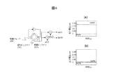
図4は、感知ピックオフおよび駆動ピックオフに関する検出回路図の一例を示す。信号「RATE」および「QUAD」は、sin fr(振動周波数)シグナチャーおよびcos frシグナチャーによって同期検出される。上述したように、製造欠陥が原因で象限誤差が大きい場合、信号は図4(a)に示されるように飽和することがある。「QUAD」が図4(b)に示されるように制御されることが好ましい。 FIG. 4 shows an example of a detection circuit diagram for the sensing pickoff and the driving pickoff. The signals "RATE" and "QUAD" are synchronously detected by the sin fr (oscillation frequency) signature and the cos fr signature. As mentioned above, if the quadrant error is large due to manufacturing defects, the signal may saturate as shown in Figure 4 (a). Preferably, "QUAD" is controlled as shown in Figure 4 (b).
感知電極の横変位を回避し、低いアンカー損失など、設計の特定の特徴を維持するために、アンカーを集中させて製造周波数の分割を低減し、次の実施形態を提案する。 In order to avoid lateral displacement of the sensing electrode and maintain certain features of the design, such as low anchor loss, the anchors are concentrated to reduce the split of manufacturing frequency and the next embodiment is proposed.
実施例2は、電極がシャトルに埋め込まれたコリオリ振動ジャイロスコープの一例である。シャトルは、一方向では対称に、他方の方向では非対称に配置される。 Example 2 is an example of a Coriolis vibrating gyroscope with electrodes embedded in the shuttle. The shuttles are arranged symmetrically in one direction and asymmetrically in the other.
図5は、提案される実施形態の上面図を示す。デバイスのコアは、任意の形状の2つの同心質量であり、その質量中心はほぼ一致する。内側質量MS1および外側質量MS2の両方の質量は、実質的に同じ質量を有する。質量は均衡している。外側質量MS2は外側シャトルOSHに機械的に接続される。内側質量MS1は内側シャトルISHに機械的に接続される。 FIG. 5 shows a top view of the proposed embodiment. The core of the device is two concentric masses of arbitrary shape, the centers of mass of which are approximately coincident. The masses of both the inner mass MS1 and the outer mass MS2 have substantially the same mass. The mass is in balance. The outer mass MS2 is mechanically connected to the outer shuttle OSH. The inner mass MS1 is mechanically connected to the inner shuttle ISH.
N組の曲げビームは、アンカーACRをシャトルに、シャトルを質量MS1、MS2およびシャトルSHの各対に接続する。曲げビームは2つの機能を有してもよい。一方は可撓性ばねであり、他方は剛性リンクである。可撓性ばねFSおよび剛性リンクRLは、図5では別個に示されているが、単一部品であることができる。内側シャトルISHおよび外側シャトルOSHは、曲げビームを用いてアンカーACRに接続される。 N sets of bending beams connect the anchor ACR to the shuttle and the shuttle to each pair of masses MS1, MS2 and shuttle SH. The bending beam may have two functions. One is a flexible spring and the other is a rigid link. The flexible spring FS and the rigid link RL are shown separately in FIG. 5, but can be a single piece. The inner shuttle ISH and outer shuttle OSH are connected to the anchor ACR using bending beams.
内側質量MS1および外側質量MS2は、シャトルISH、OSHを介して相互に接続される。浮遊した質量MS1、MS2は、アンカーACRを使用して固定の基板に取り付けられる。アンカーACRは、2つの質量MS1、MS2の間に配置される。 The inner mass MS1 and the outer mass MS2 are connected to each other via shuttles ISH and OSH. The suspended masses MS1, MS2 are attached to a fixed substrate using an anchor ACR. The anchor ACR is arranged between the two masses MS1, MS2.
図1の実施形態と同じく、駆動フォーサDFが、例えば、平行板電極を有する容量によって提供される。駆動フォーサDFは、外側シャトルOSHをX方向で振動させる。また、駆動フォーサDFを、内側シャトルISHを振動させるように配置することが可能である。シャトルに埋め込まれた電極は、四角形として単純化されているが、この形状に限定されない。平行板、櫛歯、および他の形式も、変換のために使用することができる。 As in the embodiment of FIG. 1, the drive forcer DF is provided, for example, by a capacitor with parallel plate electrodes. The drive forcer DF vibrates the outer shuttle OSH in the X direction. Further, the drive forcer DF can be arranged so as to vibrate the inner shuttle ISH. The electrodes embedded in the shuttle are simplified as squares, but are not limited to this shape. Parallel plates, combs, and other formats can also be used for the conversion.
図1または図5に示されるように、2つの質量は複雑な形状と組み合わされる。2つの質量の一部は、デバイスの中心から同距離に配置される。例えば、第1の質量MS1はその中心に向かう凹部を有する。第2の質量MS2は、第1の質量MS1を取り囲み、凹部に対向する凸部を有する。接続ユニットCUは凹部と凸部との間に位置する。 As shown in FIG. 1 or 5, the two masses are combined with a complex shape. Some of the two masses are placed at the same distance from the center of the device. For example, the first mass MS1 has a recess towards its center. The second mass MS2 has a convex portion that surrounds the first mass MS1 and faces the concave portion. The connection unit CU is located between the concave portion and the convex portion.
図6は、X−Y軸での位相外れ条件における、外側質量MS2および内側質量MS1の変位の図を示す。質量は、X−Y面の任意の方向において、この位相合わせで動くことができる(2DOF)。図6では、理解を単純にするため、ばね、シャトル、アンカーが除去されている。質量の変位についてのみここで説明する。機械的センサの主な動作モードは位相外れモードである。質量は、同じ方向で、ただし図6に示されるような逆位相で振動している。 FIG. 6 shows a diagram of the displacement of the outer mass MS2 and the inner mass MS1 under the out-of-phase condition on the XY axes. The mass can move with this phasing in any direction in the XY plane (2DOF). In FIG. 6, the springs, shuttles and anchors have been removed for simplicity of understanding. Only mass displacement will be described here. The main mode of operation of mechanical sensors is the out-of-phase mode. The masses are oscillating in the same direction, but out of phase as shown in FIG.
図7は、図5に示されるデバイスの線Aにおける断面を示す。断面はラジアル軸に沿っている。図は、外側質量MS2が左に変位し、内側質量MS1が右に変位している瞬間を捕えている。 FIG. 7 shows a cross section at line A of the device shown in FIG. The cross section is along the radial axis. The figure captures the moment when the outer mass MS2 is displaced to the left and the inner mass MS1 is displaced to the right.
左側の外側シャトルOSH(L)は、2つの部分を機械的に接続する剛性リンクRL1により、外側質量の左側セグメントMS2(L)と同じ方向で動く。左側の外側シャトルOSH(L)はアンカーACR(L)から離れる方向で動く。左側の内側シャトルISH(L)は、内側質量MS1を内側シャトルISH(L)に機械的に接続する剛性リンクRL2により、内側質量MS1と同じ方向で動く。 The left outer shuttle OSH (L) moves in the same direction as the left segment MS2 (L) of the outer mass due to the rigid link RL1 which mechanically connects the two parts. The outer shuttle OSH (L) on the left side moves away from the anchor ACR (L). The left inner shuttle ISH (L) moves in the same direction as the inner mass MS1 due to the rigid link RL2 which mechanically connects the inner mass MS1 to the inner shuttle ISH (L).
左側の内側シャトルISH(L)および外側シャトルOSH(L)は反対方向で動く。内側シャトルISH(L)および内側質量MS1によって働く力、ならびに左側の外側シャトルOSH(L)および外側質量MS2(L)によって働く力が同じ場合、結果として得られるアンカーACR(L)に対する力は無効になる。これによって、アンカーACR(L)を通した基板SUBに対するエネルギー損失が低減される。 The left inner shuttle ISH (L) and outer shuttle OSH (L) move in opposite directions. If the forces exerted by the inner shuttle ISH (L) and the inner mass MS1 and the left outer shuttle OSH (L) and the outer mass MS2 (L) are the same, the force on the resulting anchor ACR (L) is null. become. This reduces energy loss to the substrate SUB through the anchor ACR (L).
内側質量MS1および右側の内側シャトルISH(R)は、内側質量MS1を内側シャトルISH(R)に機械的に接続する剛性リンクRL3により、同じ方向(右)で動く。右側の内側シャトルISH(R)は、アンカーACR(R)に向かって動き、右側の内側シャトルISH(R)とアンカーACR(R)との間で軟性リンクFS3の曲げを圧縮する。右側の外側シャトルOSH(R)および外側質量MS2(R)は、外側シャトルOSH(R)および外側質量MS2(R)を機械的に接続する剛性リンクRL4により、同じ方向(左)で動く。右側の外側シャトルOSH(R)は、アンカーACR(R)に向かって動き、外側シャトルOSH(R)とアンカーACR(R)との間で軟性リンクFS4を曲げる。内側質量MS1および右側の内側シャトルISH(R)によって働く力、ならびに外側質量MS2(R)および右側の外側シャトルOSH(R)によって働く力が同じ場合、アンカーACR(R)に働く力は無効であり、アンカーACR(R)を通した基板SUBへのエネルギーの漏れが回避される。 The inner mass MS1 and the right inner shuttle ISH (R) move in the same direction (right) by means of a rigid link RL3 which mechanically connects the inner mass MS1 to the inner shuttle ISH (R). The right inner shuttle ISH (R) moves towards the anchor ACR (R) and compresses the bend of the flexible link FS3 between the right inner shuttle ISH (R) and the anchor ACR (R). The right outer shuttle OSH (R) and outer mass MS2 (R) move in the same direction (left) by a rigid link RL4 that mechanically connects the outer shuttle OSH (R) and outer mass MS2 (R). The right outer shuttle OSH (R) moves towards the anchor ACR (R), bending the soft link FS4 between the outer shuttle OSH (R) and the anchor ACR (R). If the force exerted by the inner mass MS1 and the right inner shuttle ISH (R) and the force exerted by the outer mass MS2 (R) and the right outer shuttle OSH (R) are the same, the force exerted on the anchor ACR (R) is ineffective. Yes, leakage of energy through the anchor ACR (R) to the substrate SUB is avoided.
上述の説明では、剛性リンクRL1、RL2、RL3、およびRL4のばね定数は、ラジアル軸方向で大きく(剛性であり)、可撓性リンク(ばね)FS1、FS2、FS3、およびFS4のばね定数は、ラジアル方向で小さい(弾性である)。 In the above description, the spring constants of the rigid links RL1, RL2, RL3, and RL4 are large (rigid) in the radial axis direction, and the spring constants of the flexible links (springs) FS1, FS2, FS3, and FS4 are , Small in the radial direction (elastic).
図6および7によって説明される現象は、実施例1によってももたらされる。 The phenomenon described by FIGS. 6 and 7 is also brought about by Example 1.
図8は、図5および7の改善されたシャトルの詳細を示す。要素の多くは、上記パラグラフに記載している。図7で説明したように、外側シャトルOSHからアンカーACRまでの可撓性リンク(弾性ばね)FS1は、X方向で低い剛性定数を有する。外側シャトルOSHから外側試験質量MS2までの剛性リンク(弾性ばね)RL1は、X方向で高い剛性定数を有する。 FIG. 8 shows details of the improved shuttle of FIGS. 5 and 7. Many of the elements are listed in the paragraph above. As explained in FIG. 7, the flexible link (elastic spring) FS1 from the outer shuttle OSH to the anchor ACR has a low stiffness constant in the X direction. The rigid link (elastic spring) RL1 from the outer shuttle OSH to the outer proof mass MS2 has a high stiffness constant in the X direction.
Y方向では、外側シャトルOSHからアンカーACRまでの剛性リンクRLY1は、Y方向で高い剛性定数を有する。外側シャトルOSHから外側試験質量MS2までの可撓性リンクFSY1は、Y方向で低い剛性定数を有する。 In the Y direction, the outer shuttle OSH to anchor ACR rigid link RLY1 has a high stiffness constant in the Y direction. The flexible link FSY1 from the outer shuttle OSH to the outer proof mass MS2 has a low stiffness constant in the Y direction.
図7で説明したように、内側シャトルISHからアンカーACRまでの可撓性リンク(弾性ばね)FS2は、X方向で低い剛性定数を有する。内側シャトルISHから内側試験質量MS1までの剛性リンク(弾性ばね)RL2は、X方向で高い剛性定数を有する。 As explained in FIG. 7, the flexible link (elastic spring) FS2 from the inner shuttle ISH to the anchor ACR has a low stiffness constant in the X direction. The rigid link (elastic spring) RL2 from the inner shuttle ISH to the inner proof mass MS1 has a high stiffness constant in the X direction.
Y方向では、内側シャトルISHからアンカーACRまでの剛性リンクRLY2は、Y方向で高い剛性定数を有する。内側シャトルISHから内側試験質量MS1までの可撓性リンクFSY2は、Y方向で低い剛性定数を有する。 In the Y direction, the rigid link RLY2 from the inner shuttle ISH to the anchor ACR has a high stiffness constant in the Y direction. The flexible link FSY2 from the inner shuttle ISH to the inner proof mass MS1 has a low stiffness constant in the Y direction.
外側シャトルOSHおよび内側シャトルISHは、X方向で低い剛性定数を有する可撓性リンクFSBによって接続される。各シャトルOSH、ISHは、電極に対応する変換器SFTのための複数の空間を有する。 The outer shuttle OSH and the inner shuttle ISH are connected by a flexible link FSB which has a low stiffness constant in the X direction. Each shuttle OSH, ISH has a plurality of spaces for the transducer SFT corresponding to the electrodes.
シャトルOSH、ISHを質量MS1、MS2に、シャトルOSH、ISHをアンカーACRに接続するばね(可撓性リンク)は、一方向では非常に弾性であり、他方向では非常に剛性であるものと知ることが重要である。この事実によって、シャトルは一方向でのみ変位し(1DOF)、試験質量がXY面の両方の方向で動くことが可能になる(2DOF)。それに加えて、一方向で非常に弾性であり、他方向では剛性であるという条件を満たす限り、ばねの好ましい形状または幾何学形状は存在しない。上述の構造によれば、シャトルOSHおよびISHは、X方向振動およびY方向振動のリンク機構を切断する。したがって、象限誤差(QUAD)が減少する。 Know that the springs (flexible links) connecting the shuttles OSH, ISH to the masses MS1, MS2 and the shuttles OSH, ISH to the anchor ACR are very elastic in one direction and very rigid in the other direction. This is very important. This fact allows the shuttle to be displaced in only one direction (1 DOF), allowing the proof mass to move in both directions in the XY plane (2 DOF). In addition, there is no preferred shape or geometry for the spring, as long as it is very elastic in one direction and rigid in the other direction. According to the structure described above, the shuttles OSH and ISH disconnect the X-direction vibration and Y-direction vibration link mechanisms. Therefore, the quadrant error (QUAD) is reduced.
集中アンカーを保持するために、非対称のシャトルを使用する。図8では、対称軸Sを規定する。2つの試験質量の質量中心CM(通常、2つの質量の中心は一致する)から、アンカーの幾何学中心ACRCまでの線Sを追跡することができる。シャトルOSH、ISHは、ばねの構成により、この方向に沿ってのみ変位する。上述の線Sに対するシャトル・ばね・アンカーモジュールを観察した場合、シャトル・ばね・アンカー構造の両方が完全対称を示す。しかしながら、アンカーの質量中心と交差する線SYを垂直に引いた場合、ばね・シャトル・アンカーモジュール(SSA、一組のばね、シャトル、アンカー)またはCUが、この最後の線SYに対して非対称であるのを見ることができる。後者は、シャトルの対称性または非対称性を規定する対称軸を規定する。 An asymmetric shuttle is used to hold the central anchor. In FIG. 8, the axis of symmetry S is defined. A line S can be traced from the center of mass CM of the two test masses (usually the two centers of mass coincide) to the geometric center of the anchor ACRC. The shuttles OSH, ISH are displaced only along this direction due to the spring configuration. When observing the shuttle-spring-anchor module for line S above, both shuttle-spring-anchor structures show perfect symmetry. However, if a line SY intersecting the center of mass of the anchor is drawn vertically, the spring-shuttle anchor module (SSA, set of springs, shuttle, anchor) or CU will be asymmetric with respect to this last line SY. You can see it. The latter defines the axis of symmetry that defines the symmetry or asymmetry of the shuttle.
設計の柔軟性は、非対称のシャトルを適用することによって改善される。大きい信号を獲得するため、大型電極をシャトルに挿入するのは簡単である。図8によって説明される設計規則に従っている限り、非対称設計は、精度信号の点で悪影響を与えない。シャトルOSHおよびISHの質量は、質量MS1およびMS2の同じ共振周波数を得るために同じであるべきである。 Design flexibility is improved by applying an asymmetric shuttle. It is easy to insert a large electrode into the shuttle to obtain a large signal. As long as the design rules described by FIG. 8 are followed, the asymmetrical design has no adverse effect on the accuracy signal. The masses of shuttle OSH and ISH should be the same in order to obtain the same resonant frequency of masses MS1 and MS2.
改善点の別の重要な態様は、集中アンカーの定義である。先に紹介した図3では、チップの面積をAcとして、また接続ユニットCUの面積をAsとして、図式的に描写する。面積Asは、接続ユニットCU全体を包含する面積として規定される。完全な機能性およびばねの無限小面積Acを有するセンサを技術的に実現できる場合、理想的には、周波数分割を排除するか、または少なくとも無限小に低減することができる。理想のAs/Ac比はほぼ0である。 Another important aspect of the improvement is the definition of centralized anchors. In FIG. 3 introduced above, the area of the chip is represented by Ac and the area of the connection unit CU is represented by As. The area As is defined as an area including the entire connection unit CU. If a sensor with perfect functionality and an infinitesimal area Ac of the spring could be technically realized, ideally the frequency division could be eliminated or at least reduced to infinity. The ideal As / Ac ratio is almost zero.
しかしながら、後者は実際のデバイスに実装することが困難である。駆動および感知モードで同じ周波数を要する、センサの実際の実現例は、ばねの有限の面積を有する。我々は集中アンカーを、0.7未満、好ましくは0.5以下のAc/Asとして規定する。文献では、シリコン系の微小加工ジャイロスコープのほとんどは、0.8よりも大きいAs/Ac比を提示する。この値よりも低いAs/Acを有するデバイスの実際の実現例はない。 However, the latter is difficult to implement in an actual device. A practical implementation of the sensor, which requires the same frequency in the drive and sense modes, has a finite area of spring. We define lumped anchors as Ac / As below 0.7, preferably below 0.5. In the literature, most silicon-based micromachined gyroscopes offer As / Ac ratios greater than 0.8. There are no real implementations of devices with As / Ac lower than this value.
この実現例において考慮する別の重要な態様は、周波数を低減し、有効変換器面積を増大させるため、電極の数、電極の面積、シャトルのサイズ、および垂下した質量のサイズを増大させることができる点である。ただし、質量中心CMとアンカーの中心ACRCとの間の距離、図8のDを、常にできるだけ小さく保ち、したがって集中アンカーアーキテクチャを保つ。最も重要なのは、As/Ac比を増大させることなく、デバイスの面積、電極の数、および質量の形状を修正できる点である。 Another important aspect to consider in this implementation is to reduce the frequency and increase the effective transducer area, thus increasing the number of electrodes, the area of the electrodes, the size of the shuttle, and the size of the drooping mass. It is a point that can be done. However, the distance between the center of mass CM and the center ACRC of the anchor, D in Fig. 8, is always kept as small as possible, thus keeping the centralized anchor architecture. Most importantly, the device area, number of electrodes, and mass shape can be modified without increasing the As / Ac ratio.
図9は、図8の内側質量MS1および外側質量MS2の変位の詳細を示す。図9は、2つの機械的モードに関する可撓性リンクの変形を示し、質量MS1、MS2がXまたはYで動いているときのシャトルOSH、ISHが説明される。この図では、Y変位はラジアル軸に垂直、または対称軸SYに平行である。X変位は、ラジアル軸に平行であり、対称軸SYに垂直である。 FIG. 9 shows details of the displacement of the inner mass MS1 and the outer mass MS2 of FIG. FIG. 9 shows a flexible link variant for two mechanical modes, illustrating the shuttle OSH, ISH when the masses MS1, MS2 are moving in X or Y. In this figure, the Y displacement is perpendicular to the radial axis or parallel to the axis of symmetry SY. The X displacement is parallel to the radial axis and perpendicular to the axis of symmetry SY.
図9(a)に示されるように、質量MS1、MS2がY軸において位相外れ形式で動いているとき、内側および外側質量を内側および外側シャトルとそれぞれ接続するばねは、Y方向で弾性である。同時に、内側および外側シャトルをアンカーと接続するばねは、Y方向で剛性である。その結果、試験質量MS1、MS2はY方向で自由に振動するが、シャトルはX方向で「係止」される。それらは動かない。 As shown in FIG. 9 (a), when the masses MS1, MS2 are moving out of phase in the Y-axis, the springs connecting the inner and outer masses with the inner and outer shuttles respectively are elastic in the Y direction. . At the same time, the springs that connect the inner and outer shuttles with the anchor are rigid in the Y direction. As a result, the proof masses MS1, MS2 are free to oscillate in the Y direction, but the shuttle is "locked" in the X direction. They don't move.
次に、内側および外側質量がX軸に沿って位相外れの変位で動いているときに何が起こるかを分析する。図9(b)に示されるように、内側および外側質量を内側および外側シャトルとそれぞれ接続する弾性ばねは、X方向に沿って剛性であり、それによって内側シャトルISHが内側質量MS1の変位に追随し、外側シャトルOSHが外側質量MS2の変位に追随する。同時に、内側および外側シャトルをアンカーと接続する機械的コネクタは、X軸に沿って可撓性であり(ただし、Y軸では剛性である)、その結果、シャトル(および試験質量)は、外側質量の変位にしたがって、互いに近付き、また互いから離れる。内側および外側シャトルは、ラジアル方向で弾性であるばねと機械的に接続される。このばねの目的は、内側および外側質量の振動を機械的に同期させることである。 Next, analyze what happens when the inner and outer masses are moving out of phase along the X axis. As shown in FIG. 9 (b), the elastic springs connecting the inner and outer masses with the inner and outer shuttles respectively are rigid along the X direction, so that the inner shuttle ISH follows the displacement of the inner mass MS1. Then, the outer shuttle OSH follows the displacement of the outer mass MS2. At the same time, the mechanical connector that connects the inner and outer shuttles to the anchor is flexible along the X axis (but rigid in the Y axis) so that the shuttle (and proof mass) is As they move closer to and further from each other. The inner and outer shuttles are mechanically connected with springs that are elastic in the radial direction. The purpose of this spring is to mechanically synchronize the vibrations of the inner and outer masses.
この改善例で示されるような、任意の結合された発振器システムは、任意の軸で位相が逆である、結合共振モードを有する。上述の逆相モードがあり、また次に、対応する同相モードがある。同相モードでは、両方の質量が同じ位相の同じ方向で動いている。同相モードでは、内側および外側質量両方の質量中心間の相対距離は一定である。 Any coupled oscillator system, as shown in this refinement, has a coupled resonant mode that is out of phase on any axis. There is a reverse phase mode described above, and then there is a corresponding common mode. In in-phase mode, both masses are moving in the same phase and in the same direction. In common mode, the relative distance between the center of mass of both the inner and outer masses is constant.
また、このモードは、少なくともXおよびY軸で観察することができるが、このモードをZ軸で観察することが可能である。同相および位相外れねじりモードも可能である。ジャイロスコープの動作において、逆相モードは、上述の性質によって機能的モードと見なされる。また、同相モードは望ましくない寄生性の機械的モードと見なされる。一般に、機械的干渉を回避するため、両方のモードは互いから離隔しているべきである。同相モードはまた、線形加速を計測するのに使用することができる。 Also, this mode can be observed at least in the X and Y axes, but it is possible to observe this mode in the Z axis. In-phase and out-of-phase twist modes are also possible. In the operation of the gyroscope, the anti-phase mode is considered a functional mode due to the above properties. Also, the common mode is considered an unwanted parasitic mechanical mode. Generally, both modes should be separated from each other to avoid mechanical interference. The common mode can also be used to measure linear acceleration.
ラジアル軸に対する垂直方向で質量MS1、MS2をシャトルOSH、ISHと接続するばねの剛性定数をkysとし、ラジアル軸方向でシャトルOSH、ISHをアンカーACRと接続するばねの剛性定数をKxaとし、内側および外側質量の質量をそれぞれmiおよびmoとし、シャトル間の有効ばねをKcと見なす。Kcとkysとの間の関係を制御することによって、同相および位相外れモードの間の周波数分離を制御することができる。 The stiffness constant of the spring that connects the masses MS1 and MS2 to the shuttles OSH and ISH in the direction perpendicular to the radial axis is k ys, and the stiffness constant of the spring that connects the shuttles OSH and ISH to the anchor ACR in the radial direction is K xa . and m i and m o inner and outer mass of the mass respectively, consider the effective spring between the shuttle and K c. By controlling the relationship between K c and k ys , the frequency separation between in-phase and out-of-phase modes can be controlled.
図10は、質量の感知および励起のための静電電極の一例を示す。このデバイスは、駆動フォーサDF、駆動ピックオフDP、および感知ピックオフSPのいずれにも適用される。 FIG. 10 shows an example of an electrostatic electrode for sensing and exciting mass. This device applies to any of the drive forcer DF, drive pickoff DP, and sense pickoff SP.
一例では、基板に固定された固定プレート(固定子)1001は、いくつかの平行板が間に差し挟まれた静電プレート1002、シャトルのシャトルプレート1003といった、いくつかの容量プレートを有する。この電極1002および1003は、同じ等価の変換容量を有することができ、または異なることができる。デバイスを動的に均衡させて保つため、2つの質量に加えられる力は同じであることが重要である。図面では、変換ギャップ1004は変換アンチギャップ1005よりも小さい。しかしながら、任意の構成で動作する。
In one example, a fixed plate (stator) 1001 fixed to a substrate has several capacitive plates, such as an
制御容量を増加して精度および感度を向上させ、ジャイロスコープを振動させて保つのに要するエネルギーを低減するために、解決策は、容量の数またはサイズを増大させることである。それには、電極のサイズを増大させることを要する。 To increase the controlled volume to improve accuracy and sensitivity and reduce the energy required to keep the gyroscope vibrating, the solution is to increase the number or size of the volumes. This requires increasing the size of the electrodes.
図11は、容量を効率的に増加させる、非対称のばね・シャトル・アンカーモジュールの実際の1つの実現例を示す。この特定の図では、静電プレート1002がシャトルプレート1003に組み込まれているが、図面の理解をより簡単にするため、この図には示されていない。
FIG. 11 shows one actual implementation of an asymmetric spring shuttle anchor module that effectively increases capacity. In this particular view,
ばねの形状は、一方向での弾性と、垂直方向での高い剛性とを達成するために選択されている。ばねのサイズ、形状、および材料は重要ではない。それらのいずれかを使用することができる。図11の実施形態では、ばねは、可撓性リンクおよび剛性リンクの両方の機能を有するU字ばねによって準備される。 The shape of the spring is chosen to achieve elasticity in one direction and high rigidity in the vertical direction. The size, shape, and material of the spring are not important. Any of them can be used. In the embodiment of FIG. 11, the spring is provided by a U-shaped spring that has the functions of both flexible and rigid links.
内側シャトルISHから内側質量MS1(MS1は図11には示されていない)までのU字ばね1101(「ビーム」とも呼ばれる)。ばね1101は、軸線方向軸に垂直な方向で弾性であり、ラジアル方向では静止している。
外側シャトルOSHから外側質量MS2(MS2は図11には示されていない)までのU字ばね1102。ばね1102は、軸線方向軸に垂直な方向で弾性であり、ラジアル方向では剛性である。
U-spring 1101 (also called "beam") from the inner shuttle ISH to the inner mass MS1 (MS1 not shown in FIG. 11). The spring 1101 is elastic in the direction perpendicular to the axial axis and is stationary in the radial direction.
U-spring 1102 from outer shuttle OSH to outer mass MS2 (MS2 not shown in FIG. 11). The spring 1102 is elastic in the direction perpendicular to the axial axis and rigid in the radial direction.
アンカーACRから内側シャトルISHまでのU字ばね1103。ばね1103は、ラジアル方向で弾性であり、垂直方向では剛性である。
アンカーACRと外側シャトルOSHとの間のU字ばね1104。ばね1104は、ラジアル方向で可撓性であり、垂直方向では剛性である。
U-shaped spring 1103 from anchor ACR to inner shuttle ISH. The spring 1103 is elastic in the radial direction and rigid in the vertical direction.
内側シャトルISHと外側シャトルOSHとの間でのU字ばね1105の結合。ばね1105は、ラジアル方向で可撓性であり、垂直方向では剛性である。 Coupling of U-spring 1105 between inner shuttle ISH and outer shuttle OSH. The spring 1105 is flexible in the radial direction and rigid in the vertical direction.
図12Aおよび12Bは、図11に示されるビームの変形例を示す。図12(a)では、2つの試験質量(図面に含まれない)がラジアル軸に対して垂直に位相外れモードで動いているときの、ビームの変形を見ることができる。この状況では、シャトルは、ばねの特別な構成によって、いずれの方向でも動いていない。したがって、シャトルに埋め込まれた電極の周りでの運動は無効にされる。 12A and 12B show variations of the beam shown in FIG. In FIG. 12 (a), the deformation of the beam can be seen when the two proof masses (not included in the drawing) are moving out of phase mode perpendicular to the radial axis. In this situation, the shuttle is not moving in either direction due to the special configuration of the spring. Therefore, movement around the electrodes embedded in the shuttle is counteracted.
図12(b)では、2つの質量がラジアル軸に沿って逆相モードで動いているときの、ビームの変形を見ることができる。この場合、シャトルは、関連する試験質量と同じ方向および同じ位相で動いている。この特定の例では、内側試験質量(図面には示されない)は右に動いており、対応する内側シャトルも同じである。外側試験質量(図面には示されない)は右に動いており、対応する外側シャトルも同じである。この場合、静電プレート1002とシャトルプレート1003との間のギャップは、シャトルの変位に従って変化する。
In FIG. 12 (b) the deformation of the beam can be seen when the two masses are moving in anti-phase mode along the radial axis. In this case, the shuttle is moving in the same direction and in the same phase as the associated proof mass. In this particular example, the inner proof mass (not shown in the drawing) is moving to the right, as is the corresponding inner shuttle. The outer proof mass (not shown in the drawing) is moving to the right, as is the corresponding outer shuttle. In this case, the gap between the
図13は、感知および励起用の接続ユニットCUおよび電極の可能なトポロジーを示す。図13では、集中アンカージャイロスコープの実際的な実現例を示している。この場合、円形の外側質量MS2および円形の内側質量MS1がある。互いから90°でデバイス中心の周りに分配された、4つのばね・シャトル・アンカーモジュール1300がある。各シャトル内部の静電電極はこの図には含まれない。ただし、この電極は静電作動および容量感知に必要であることが理解される。
FIG. 13 shows a possible topology of connection units CU and electrodes for sensing and excitation. FIG. 13 shows a practical implementation example of the centralized anchor gyroscope. In this case, there is a circular outer mass MS2 and a circular inner mass MS1. There are four spring
この特定の例では、32個の電極がある。すなわち、X軸の16個の電極、およびY軸の16個の電極である。軸毎の電極の数は増加させることができ、デバイスの面積は増大させることができる。しかしながら、ばねの面積を一定に保ち、それによって比As/Acを低減させることができる。それに加えて、この実施形態は4つのシャトル・ばね・アンカーモジュール1300を示しているが、他の任意の実物は8個を含むことができる。デバイスの良好な性能のため、シャトル・ばね・アンカーモジュールを含むデバイスが、XおよびYで対称であって、動的均衡および両方の軸で同じ性能を保証することが重要である。図面では、試験質量の形状は円形であるが、正方形、三角形、多角形、または他の形状も容認可能であろうことが理解される。この時点で、どの形状がより良好な性能をもたらすかを判断する研究はない。
In this particular example, there are 32 electrodes. That is, 16 electrodes on the X axis and 16 electrodes on the Y axis. The number of electrodes per axis can be increased and the area of the device can be increased. However, it is possible to keep the area of the spring constant and thereby reduce the ratio As / Ac. In addition, although this embodiment shows four shuttle
上述のジャイロスコープを制御するための回路に関して、特許文献1に記載の回路を使用することができる。内側質量MS1および外側質量MS2は、電極に電気的および機械的に結合される。感知電極DPは、駆動軸での変位を感知し、電流である感知信号を生成する。電流は、電流電圧変換器または増幅器によって電流に変換される。構成の一例は、内側試験質量MS1の電極が差動増幅器の+端子に接続され、外側試験質量MS2が差動増幅器の−端子に接続されるものである。差動増幅器出力は、位相遅れ回路を通して、反転増幅器および非反転増幅器に供給される。このように、内側質量MS1に適用される駆動信号は、外側質量MS2に適用される駆動信号に対して180°位相遅れである。増幅器は、ジャイロスコープの逆相または同相運動を制御することができる。
Regarding the circuit for controlling the gyroscope described above, the circuit described in
増幅器の出力は、位相ロックループ(PLL)に供給することができる。PLLの出力は、反転および非反転増幅器に返すことができる。 The output of the amplifier can be fed into a phase locked loop (PLL). The output of the PLL can be returned to inverting and non-inverting amplifiers.
図14は、制御回路のブロック図を示す。YおよびZ軸で感知電極によってピックアップした電流PyおよびPxは、PLL増幅器1401に供給される。信号は、発振器によって生成された、直交位相シフトした正弦sin(f)およびcos(f)と混合される。次に、信号はフィルタ1402に入力して、出力信号sx、cx、sy、cyを提供するように、寄生信号および雑音などの望ましくない周波数成分を除去する。 FIG. 14 shows a block diagram of the control circuit. The currents Py and Px picked up by the sensing electrodes on the Y and Z axes are supplied to the PLL amplifier 1401. The signal is mixed with quadrature phase shifted sine sin (f) and cos (f) produced by the oscillator. The signal is then input to filter 1402 to remove unwanted frequency components such as parasitic signals and noise to provide output signals sx, cx, sy, cy.
復調器からの出力は、振り子方程式変換器1403によって処理され、振り子変数E、Q、およびθが得られる。この変数は、比例−積分−微分(PID)ブロック1404に供給される。E変数は、2つの質量の一定振動を制御するブロックAGCに入力される。Qは、象限誤差を無効にする力を生成するQヌルに供給され、最終的に、振動を一方向でロックするのに使用されるFRBに用いられる。しかしながら、ジャイロスコープがレート積分ジャイロスコープとして動作しているとき、ブロックFRBは不活性化されるので、振動パターンを自由に処理できる。力は、座標変換器1405に供給され、そこでジャイロスコープの処理角度を使用して、力をジャイロスコープの角度と位置合わせする。座標変換器の出力は、変調器1406によって変調され、(Fx,Fy)が対応する電極に返されてジャイロスコープが制御される。
The output from the demodulator is processed by the
図15は、機械的要素1501および電極1502の可能な実現例の断面を示す。例えば、MEMSジャイロスコープがシリコンで作製され、キャップ1503によって被覆され、その機械的適合度を保存するために真空封止される。例えば、真空パッケージングは、空気減衰による損失を除去する。それに加えて、封止および被覆は、可動の小型化構造をほこりなどの外的脅威から保護する。
FIG. 15 shows a cross section of a possible implementation of
電子部品1502は、標準的な相補型金属酸化物シリコン(CMOS)技術を使用して実装することができ、アナログまたはデジタル技術を使用して、図14で説明した様々な構成ブロックすべてを実装する。機械的要素1501およびCMOS回路は、接着剤の使用によって積層方式で機械的に取り付けることができる。電気接続は、ワイヤボンディング1504を使用して行うことができる。
より高度な技術により、機械的要素とCMOS回路を、2つのチップを接続する金属ビアを使用することによって相互接続することが可能になる。それを行うため、特別に調整したプロセスを行わなければならない。他の技術により、CMOSプロセス内部でみいだすことができる金属層を使用することによって、デバイスを作製することが可能になり、結果として異種集積の必要性が除去される。これはCMOS−MEMSプロセスと呼ばれる。MEMS要素およびCMOS制御電子部品によって形成された積層デバイスは、航法または位置制御システムの他の部品との相互接続を容易にするため、プラスチックまたはセラミックのパッケージ内部でパッケージ化される。 More sophisticated technology allows interconnecting mechanical elements and CMOS circuits by using metal vias that connect the two chips. In order to do that, specially tailored processes must be undertaken. Other techniques allow devices to be made by using metal layers that can be found within CMOS processes, resulting in the elimination of the need for heterogeneous integration. This is called the CMOS-MEMS process. Stacked devices formed by MEMS elements and CMOS controlled electronics are packaged inside plastic or ceramic packages to facilitate interconnection with other components of navigation or position control systems.
地下航法では、GPSなどの外部位置基準へのアクセスがない。地下トンネルのマップが車両メモリに格納される。可動プラットフォームは、IMUを使用して自身を自己位置決めする。速度の他に、IMUは、車両の操舵を規制するために、地面に垂直な軸を中心とした車両の回転を検出することができる。そのようにして、車両はGPSが故障停止しても安全に航行することができる。 Underground navigation does not have access to external position references such as GPS. A map of the underground tunnel is stored in the vehicle memory. The mobile platform uses the IMU to self-position itself. In addition to speed, the IMU can detect rotation of the vehicle about an axis perpendicular to the ground to regulate steering of the vehicle. In that way, the vehicle can safely navigate even if the GPS fails.
プラットフォームは高速で曲線経路を走行している。重要データにアクセスするためのインターネットとの通信は、衛星利用のデータリンクを使用して高速で行われる。通信衛星は、地球から36000kmで静止している。安全で信頼性の高いデータ転送を確保するために、車両の通信アンテナは一定して通信衛星を指していなければならない。ジャイロスコープは、可動プラットフォームの旋回および回転を検出して制御ループに入力信号を提供し、制御ループがモータを作動させてアンテナの位置を補正する。 The platform is traveling on a curved path at high speed. Communication with the Internet to access critical data is done at high speed using satellite-based data links. The communication satellite is stationary at 36000 km from the earth. In order to ensure safe and reliable data transfer, the vehicle's communication antenna must constantly point to the communication satellite. The gyroscope detects the swing and rotation of the movable platform and provides an input signal to the control loop, which activates the motor to correct the position of the antenna.
上述の実施形態によれば、駆動および感知モード間の周波数分離を低減するが、感知容量の横運動も相殺して象限誤差を低減する、作製公差の効果によって、高いQ因子を有するジャイロスコープを得ることができる。 According to the above-described embodiments, a gyroscope having a high Q factor is reduced due to the effect of manufacturing tolerance, which reduces the frequency separation between the driving and sensing modes, but also cancels the lateral movement of the sensing capacitance to reduce the quadrant error. Obtainable.
当業者であれば、本発明の範囲および趣旨から逸脱することなく、上述の実施形態の様々な適応および修正を構成できることを理解するであろう。したがって、添付の特許請求の範囲内で、本発明は、本明細書に具体的に記載したもの以外に予測されてもよいことを理解されたい。 Those skilled in the art will appreciate that various adaptations and modifications of the above-described embodiments can be made without departing from the scope and spirit of the invention. Therefore, it is to be understood that within the scope of the appended claims, the present invention may be envisioned other than as specifically described herein.
MS1 第1の質量
MS2 第2の質量
ACR アンカー
SH シャトル
OSH 外側シャトル
ISH 内側シャトル
CU 接続ユニット
DF 駆動フォーサ
DP 駆動ピックオフ
SP 感知ピックオフ
SF 感知フォーサ
RL 剛性リンク
FS 可撓性ばね
MS1 1st mass MS2 2nd mass ACR Anchor SH Shuttle OSH Outer shuttle ISH Inner shuttle CU Connection unit DF Drive forcer DP Drive pickoff SP Sensing pickoff SF Sensing forcer RL Rigid link FS Flexible spring
Claims (12)
前記半導体チップが、
基板と、
X−Y面の任意の方向で移動することができる第1の質量と、
前記X−Y面の任意の方向で移動することができる第2の質量と、
前記第1の質量と前記第2の質量との間に位置し、前記第1の質量および前記第2の質量を機械的に接続する接続ユニットとを備え、
前記接続ユニットが、
前記基板に固着されたアンカーと、
前記アンカーと前記第1の質量との間に位置する第1のシャトルと、
前記アンカーと前記第2の質量との間に位置する第2のシャトルと、
前記アンカーおよび前記第1のシャトルを接続する第1のビームと、
前記アンカーおよび前記第2のシャトルを接続する第2のビームと、
前記第1の質量および前記第1のシャトルを接続する第3のビームと、
前記第2の質量および前記第2のシャトルを接続する第4のビームと、
前記第1のシャトルおよび前記第2のシャトルを接続する第5のビームとを備え、
前記アンカーが前記第1のシャトルと前記第2のシャトル,との間に位置し、
前記第1のシャトルおよび前記第2のシャトルが異なる形状を有し、それぞれ電極を有
する、ジャイロスコープ。 A gyroscope including a semiconductor chip,
The semiconductor chip is
Board,
A first mass that can move in any direction of the XY plane;
A second mass that can move in any direction of the XY plane;
A connecting unit that is located between the first mass and the second mass and mechanically connects the first mass and the second mass;
The connection unit is
An anchor fixed to the substrate,
A first shuttle located between the anchor and the first mass;
A second shuttle located between the anchor and the second mass;
A first beam connecting the anchor and the first shuttle;
A second beam connecting the anchor and the second shuttle;
A third beam connecting the first mass and the first shuttle;
A fourth beam connecting the second mass and the second shuttle;
A fifth beam connecting the first shuttle and the second shuttle,
The anchor is located between the first shuttle and the second shuttle,
A gyroscope, wherein the first shuttle and the second shuttle have different shapes and each has an electrode.
前記第2のビームがY方向よりもX方向で可撓性であり、
前記第3のビームがX方向よりもY方向で可撓性であり、
前記第4のビームがX方向よりもY方向で可撓性である、請求項1に記載のジャイロスコープ。 The first beam is more flexible in the X direction than in the Y direction,
The second beam is more flexible in the X direction than in the Y direction,
The third beam is more flexible in the Y direction than in the X direction,
The gyroscope of claim 1, wherein the fourth beam is more flexible in the Y direction than the X direction.
前記第1のシャトルおよび前記第2のシャトルが前記線Sに対して対称性を示し、
前記第1のシャトルおよび前記第2のシャトルが前記線SYに対して非対称性を示す、請求項5に記載のジャイロスコープ。 When defining a line S linking the center of mass CM and the center of the anchor and defining a line SY perpendicular to the line S and passing through the center of the anchor,
The first shuttle and the second shuttle exhibit symmetry with respect to the line S,
The gyroscope according to claim 5, wherein the first shuttle and the second shuttle exhibit an asymmetry with respect to the line SY.
前記第2の質量が、前記第1の質量を取り囲み、前記凹部に対向する凸部を有し、
前記接続ユニットが前記凹部と前記凸部との間に位置する、請求項1に記載のジャイロスコープ。 The first mass has a recess toward the center,
The second mass surrounds the first mass and has a convex portion facing the concave portion,
The gyroscope according to claim 1, wherein the connection unit is located between the concave portion and the convex portion.
前記第2のシャトルの前記電極が、前記一方向での前記第2のシャトルの振動を感知する、請求項1に記載のジャイロスコープ。 The electrodes of the first shuttle vibrate the first shuttle in one direction,
The gyroscope of claim 1, wherein the electrodes of the second shuttle sense vibrations of the second shuttle in the one direction.
前記第2のシャトルの前記電極が、前記一方向での前記第2のシャトルの振動を感知する、請求項1に記載のジャイロスコープ。 The electrodes of the first shuttle sense vibrations of the first shuttle in one direction,
The gyroscope of claim 1, wherein the electrodes of the second shuttle sense vibrations of the second shuttle in the one direction.
As対Acの比が0.7未満である、請求項1に記載のジャイロスコープ。 When the area Ac is defined as the area of the semiconductor chip and the area As is defined as the area including all the connection units,
The gyroscope of claim 1, wherein the ratio of As to Ac is less than 0.7.
Priority Applications (2)
| Application Number | Priority Date | Filing Date | Title |
|---|---|---|---|
| JP2017050201A JP6689227B2 (en) | 2017-03-15 | 2017-03-15 | Gyroscope |
| US15/911,270 US10520314B2 (en) | 2017-03-15 | 2018-03-05 | Gyroscope |
Applications Claiming Priority (1)
| Application Number | Priority Date | Filing Date | Title |
|---|---|---|---|
| JP2017050201A JP6689227B2 (en) | 2017-03-15 | 2017-03-15 | Gyroscope |
Publications (2)
| Publication Number | Publication Date |
|---|---|
| JP2018155499A JP2018155499A (en) | 2018-10-04 |
| JP6689227B2 true JP6689227B2 (en) | 2020-04-28 |
Family
ID=63520024
Family Applications (1)
| Application Number | Title | Priority Date | Filing Date |
|---|---|---|---|
| JP2017050201A Expired - Fee Related JP6689227B2 (en) | 2017-03-15 | 2017-03-15 | Gyroscope |
Country Status (2)
| Country | Link |
|---|---|
| US (1) | US10520314B2 (en) |
| JP (1) | JP6689227B2 (en) |
Families Citing this family (9)
| Publication number | Priority date | Publication date | Assignee | Title |
|---|---|---|---|---|
| GB2560334A (en) * | 2017-03-07 | 2018-09-12 | Atlantic Inertial Systems Ltd | Gyroscope in-field prognostics |
| JP6689227B2 (en) * | 2017-03-15 | 2020-04-28 | 株式会社日立製作所 | Gyroscope |
| EP3665436A4 (en) * | 2017-08-11 | 2021-05-19 | HRL Laboratories, LLC | A silicon multi-mode coriolis vibratory gyroscopes having high order rotationally symmetric mechanical structure and 32 electrodes |
| FR3098295B1 (en) * | 2018-12-20 | 2021-11-19 | Thales Sa | Improved inertial sensor |
| US11656077B2 (en) | 2019-01-31 | 2023-05-23 | Analog Devices, Inc. | Pseudo-extensional mode MEMS ring gyroscope |
| EP3696502B1 (en) * | 2019-02-15 | 2022-04-06 | Murata Manufacturing Co., Ltd. | Gyroscope with double input |
| JP7188311B2 (en) | 2019-07-31 | 2022-12-13 | セイコーエプソン株式会社 | Gyro sensors, electronic devices, and mobile objects |
| CN110514189B (en) * | 2019-09-03 | 2020-12-01 | 深迪半导体(上海)有限公司 | Gyroscope and method for fusing and correcting quadrature error of gyroscope |
| CN113842646B (en) * | 2021-09-27 | 2023-04-07 | 广州市三宝动漫玩具有限公司 | Top cover and top toy |
Family Cites Families (12)
| Publication number | Priority date | Publication date | Assignee | Title |
|---|---|---|---|---|
| US7036372B2 (en) * | 2003-09-25 | 2006-05-02 | Kionix, Inc. | Z-axis angular rate sensor |
| EP1677073B1 (en) * | 2004-12-29 | 2013-06-19 | STMicroelectronics Srl | Micro-electro-mechanical gyroscope having electrically insulated regions |
| JP5301767B2 (en) * | 2006-06-13 | 2013-09-25 | 日立オートモティブシステムズ株式会社 | Inertial sensor |
| US7900512B2 (en) * | 2006-07-25 | 2011-03-08 | Denso Corporation | Angular rate sensor |
| JP5450451B2 (en) * | 2008-02-05 | 2014-03-26 | インベンセンス,インク. | XY Axis Dual Mass Tuning Fork Gyroscope with Vertically Integrated Electronic Circuits and Wafer Scale Sealed Packaging |
| IT1394007B1 (en) * | 2009-05-11 | 2012-05-17 | St Microelectronics Rousset | MICROELETTROMECANICAL STRUCTURE WITH IMPROVED REJECTION OF ACCELERATION DISORDERS |
| JP4968298B2 (en) * | 2009-09-04 | 2012-07-04 | 株式会社デンソー | Vibration type angular velocity sensor |
| JP5682267B2 (en) * | 2010-01-12 | 2015-03-11 | ソニー株式会社 | Angular velocity sensor |
| JP5773844B2 (en) * | 2011-10-31 | 2015-09-02 | 三菱プレシジョン株式会社 | Vibration type gyro with excellent output stability |
| DE102013208817A1 (en) * | 2013-05-14 | 2014-11-20 | Robert Bosch Gmbh | Yaw rate sensor with a main extension plane having a substrate for detecting a rate of rotation |
| US10247554B2 (en) * | 2014-09-24 | 2019-04-02 | The Regents Of The University Of California | Fully balanced micro-machined inertial sensor |
| JP6689227B2 (en) * | 2017-03-15 | 2020-04-28 | 株式会社日立製作所 | Gyroscope |
-
2017
- 2017-03-15 JP JP2017050201A patent/JP6689227B2/en not_active Expired - Fee Related
-
2018
- 2018-03-05 US US15/911,270 patent/US10520314B2/en not_active Expired - Fee Related
Also Published As
| Publication number | Publication date |
|---|---|
| JP2018155499A (en) | 2018-10-04 |
| US10520314B2 (en) | 2019-12-31 |
| US20180266822A1 (en) | 2018-09-20 |
Similar Documents
| Publication | Publication Date | Title |
|---|---|---|
| JP6689227B2 (en) | Gyroscope | |
| Geiger et al. | A new silicon rate gyroscope | |
| USRE45855E1 (en) | Microelectromechanical sensor with improved mechanical decoupling of sensing and driving modes | |
| US6848304B2 (en) | Six degree-of-freedom micro-machined multi-sensor | |
| US7617728B2 (en) | Tuning fork gyroscope | |
| US6701786B2 (en) | Closed loop analog gyro rate sensor | |
| US10809061B2 (en) | Vibratory gyroscope including a plurality of inertial bodies | |
| US7640803B1 (en) | Micro-electromechanical system inertial sensor | |
| US8397568B2 (en) | Bias measurement for MEMS gyroscopes and accelerometers | |
| EP1752735B1 (en) | Vibratory gyro bias error cancellation using mode reversal | |
| JP2006525514A (en) | Microfabricated multi-sensor for uniaxial acceleration detection and biaxial angular velocity detection | |
| JP2007509346A (en) | XY axis dual mass tuning fork gyroscope with vertically integrated electronics and wafer scale sealed packaging | |
| US20200346920A1 (en) | Systems and methods for bias suppression in a non-degenerate mems sensor | |
| Gill et al. | MEMS multi-vibrating ring gyroscope for space applications | |
| Senkal et al. | Dual foucault pendulum gyroscope | |
| WO2001079862A1 (en) | Z-axis micro-gyro | |
| JP6527235B2 (en) | Gyroscope | |
| Baranov et al. | A novel multiple-axis MEMS gyroscope-accelerometer with decoupling frames | |
| US20200292313A1 (en) | In-plane non-degenerate coriolis vibratory gyroscope | |
| JP6146592B2 (en) | Physical quantity sensor, electronic equipment | |
| Bo et al. | Research on a new decoupled dual-mass micro-gyroscope | |
| Serrano et al. | MEMS inertial sensors | |
| Seok et al. | Design, analysis, and experimental results of micromachined single-structure triaxis vibratory gyroscope with advanced coupling mechanism | |
| US20230400303A1 (en) | Inertial navigation sensor with reduced footprint | |
| Chang et al. | Design and testing of dual-axial gyroscope |
Legal Events
| Date | Code | Title | Description |
|---|---|---|---|
| A621 | Written request for application examination |
Free format text: JAPANESE INTERMEDIATE CODE: A621 Effective date: 20190405 |
|
| A977 | Report on retrieval |
Free format text: JAPANESE INTERMEDIATE CODE: A971007 Effective date: 20200108 |
|
| A131 | Notification of reasons for refusal |
Free format text: JAPANESE INTERMEDIATE CODE: A131 Effective date: 20200121 |
|
| A521 | Request for written amendment filed |
Free format text: JAPANESE INTERMEDIATE CODE: A523 Effective date: 20200227 |
|
| TRDD | Decision of grant or rejection written | ||
| A01 | Written decision to grant a patent or to grant a registration (utility model) |
Free format text: JAPANESE INTERMEDIATE CODE: A01 Effective date: 20200331 |
|
| A61 | First payment of annual fees (during grant procedure) |
Free format text: JAPANESE INTERMEDIATE CODE: A61 Effective date: 20200407 |
|
| R150 | Certificate of patent or registration of utility model |
Ref document number: 6689227 Country of ref document: JP Free format text: JAPANESE INTERMEDIATE CODE: R150 |
|
| LAPS | Cancellation because of no payment of annual fees |