JP6684929B2 - RELATED DEVICES, SYSTEMS, AND METHODS FOR DETERMINING PULSE WAVE Velocity Using Intravascular Pressure Measurements and External Ultrasound Imaging - Google Patents
RELATED DEVICES, SYSTEMS, AND METHODS FOR DETERMINING PULSE WAVE Velocity Using Intravascular Pressure Measurements and External Ultrasound Imaging Download PDFInfo
- Publication number
- JP6684929B2 JP6684929B2 JP2018560138A JP2018560138A JP6684929B2 JP 6684929 B2 JP6684929 B2 JP 6684929B2 JP 2018560138 A JP2018560138 A JP 2018560138A JP 2018560138 A JP2018560138 A JP 2018560138A JP 6684929 B2 JP6684929 B2 JP 6684929B2
- Authority
- JP
- Japan
- Prior art keywords
- blood vessel
- pressure
- processing system
- data
- velocity
- Prior art date
- Legal status (The legal status is an assumption and is not a legal conclusion. Google has not performed a legal analysis and makes no representation as to the accuracy of the status listed.)
- Expired - Fee Related
Links
- 238000000034 method Methods 0.000 title claims description 65
- 238000009530 blood pressure measurement Methods 0.000 title description 8
- 238000012285 ultrasound imaging Methods 0.000 title description 4
- 210000004204 blood vessel Anatomy 0.000 claims description 137
- 238000012545 processing Methods 0.000 claims description 135
- 238000003384 imaging method Methods 0.000 claims description 132
- 238000002604 ultrasonography Methods 0.000 claims description 59
- 239000012530 fluid Substances 0.000 claims description 55
- 230000008660 renal denervation Effects 0.000 claims description 35
- 210000002254 renal artery Anatomy 0.000 claims description 32
- 238000012544 monitoring process Methods 0.000 claims description 25
- 238000004891 communication Methods 0.000 claims description 19
- 230000008901 benefit Effects 0.000 claims description 13
- 230000008859 change Effects 0.000 claims description 13
- 230000000007 visual effect Effects 0.000 claims description 6
- 230000001225 therapeutic effect Effects 0.000 claims description 5
- 238000002560 therapeutic procedure Methods 0.000 claims description 5
- 230000001360 synchronised effect Effects 0.000 claims description 2
- 210000003734 kidney Anatomy 0.000 description 44
- 230000002889 sympathetic effect Effects 0.000 description 24
- 206010020772 Hypertension Diseases 0.000 description 21
- 210000002820 sympathetic nervous system Anatomy 0.000 description 21
- 210000005036 nerve Anatomy 0.000 description 17
- 230000000747 cardiac effect Effects 0.000 description 16
- 210000002216 heart Anatomy 0.000 description 16
- 210000004369 blood Anatomy 0.000 description 15
- 239000008280 blood Substances 0.000 description 15
- 230000036772 blood pressure Effects 0.000 description 15
- 239000000523 sample Substances 0.000 description 14
- 230000008035 nerve activity Effects 0.000 description 12
- 230000000694 effects Effects 0.000 description 11
- 210000003484 anatomy Anatomy 0.000 description 10
- 206010047139 Vasoconstriction Diseases 0.000 description 9
- 230000004913 activation Effects 0.000 description 8
- 210000004556 brain Anatomy 0.000 description 8
- 208000020832 chronic kidney disease Diseases 0.000 description 8
- 102100028255 Renin Human genes 0.000 description 7
- 108090000783 Renin Proteins 0.000 description 7
- 238000010586 diagram Methods 0.000 description 7
- 239000011734 sodium Substances 0.000 description 7
- 230000025033 vasoconstriction Effects 0.000 description 7
- DGAQECJNVWCQMB-PUAWFVPOSA-M Ilexoside XXIX Chemical compound C[C@@H]1CC[C@@]2(CC[C@@]3(C(=CC[C@H]4[C@]3(CC[C@@H]5[C@@]4(CC[C@@H](C5(C)C)OS(=O)(=O)[O-])C)C)[C@@H]2[C@]1(C)O)C)C(=O)O[C@H]6[C@@H]([C@H]([C@@H]([C@H](O6)CO)O)O)O.[Na+] DGAQECJNVWCQMB-PUAWFVPOSA-M 0.000 description 6
- 238000002592 echocardiography Methods 0.000 description 6
- 230000006870 function Effects 0.000 description 6
- 230000028327 secretion Effects 0.000 description 6
- 229910052708 sodium Inorganic materials 0.000 description 6
- 238000013517 stratification Methods 0.000 description 6
- 206010019280 Heart failures Diseases 0.000 description 5
- 210000000702 aorta abdominal Anatomy 0.000 description 5
- 230000002526 effect on cardiovascular system Effects 0.000 description 5
- 238000005259 measurement Methods 0.000 description 5
- 210000000056 organ Anatomy 0.000 description 5
- 230000008569 process Effects 0.000 description 5
- 230000036454 renin-angiotensin system Effects 0.000 description 5
- 210000005166 vasculature Anatomy 0.000 description 5
- XLYOFNOQVPJJNP-UHFFFAOYSA-N water Substances O XLYOFNOQVPJJNP-UHFFFAOYSA-N 0.000 description 5
- 206010007558 Cardiac failure chronic Diseases 0.000 description 4
- 206010041277 Sodium retention Diseases 0.000 description 4
- 230000004872 arterial blood pressure Effects 0.000 description 4
- 230000009286 beneficial effect Effects 0.000 description 4
- 230000000903 blocking effect Effects 0.000 description 4
- 230000017531 blood circulation Effects 0.000 description 4
- 208000022831 chronic renal failure syndrome Diseases 0.000 description 4
- 230000003054 hormonal effect Effects 0.000 description 4
- 229940088597 hormone Drugs 0.000 description 4
- 239000005556 hormone Substances 0.000 description 4
- 230000001631 hypertensive effect Effects 0.000 description 4
- 230000002093 peripheral effect Effects 0.000 description 4
- 208000015658 resistant hypertension Diseases 0.000 description 4
- 230000004044 response Effects 0.000 description 4
- 230000000638 stimulation Effects 0.000 description 4
- 230000008700 sympathetic activation Effects 0.000 description 4
- 208000024891 symptom Diseases 0.000 description 4
- 230000002792 vascular Effects 0.000 description 4
- 208000031481 Pathologic Constriction Diseases 0.000 description 3
- 230000005540 biological transmission Effects 0.000 description 3
- 230000001684 chronic effect Effects 0.000 description 3
- 239000003086 colorant Substances 0.000 description 3
- 230000001276 controlling effect Effects 0.000 description 3
- 230000003247 decreasing effect Effects 0.000 description 3
- 230000029142 excretion Effects 0.000 description 3
- 230000013632 homeostatic process Effects 0.000 description 3
- 230000003907 kidney function Effects 0.000 description 3
- 238000012986 modification Methods 0.000 description 3
- 230000004048 modification Effects 0.000 description 3
- 230000007383 nerve stimulation Effects 0.000 description 3
- 230000000144 pharmacologic effect Effects 0.000 description 3
- 230000009467 reduction Effects 0.000 description 3
- 230000008327 renal blood flow Effects 0.000 description 3
- 238000005070 sampling Methods 0.000 description 3
- 230000036262 stenosis Effects 0.000 description 3
- 208000037804 stenosis Diseases 0.000 description 3
- 230000009885 systemic effect Effects 0.000 description 3
- 210000001519 tissue Anatomy 0.000 description 3
- 102000004127 Cytokines Human genes 0.000 description 2
- 108090000695 Cytokines Proteins 0.000 description 2
- 206010022489 Insulin Resistance Diseases 0.000 description 2
- 208000007177 Left Ventricular Hypertrophy Diseases 0.000 description 2
- 229920002614 Polyether block amide Polymers 0.000 description 2
- 206010063897 Renal ischaemia Diseases 0.000 description 2
- 210000001015 abdomen Anatomy 0.000 description 2
- 210000001367 artery Anatomy 0.000 description 2
- 238000010009 beating Methods 0.000 description 2
- 230000006378 damage Effects 0.000 description 2
- 230000002638 denervation Effects 0.000 description 2
- 230000006866 deterioration Effects 0.000 description 2
- 238000011161 development Methods 0.000 description 2
- 210000000609 ganglia Anatomy 0.000 description 2
- 238000003780 insertion Methods 0.000 description 2
- 230000037431 insertion Effects 0.000 description 2
- 230000007246 mechanism Effects 0.000 description 2
- 210000003205 muscle Anatomy 0.000 description 2
- 210000004126 nerve fiber Anatomy 0.000 description 2
- 230000004007 neuromodulation Effects 0.000 description 2
- 239000004810 polytetrafluoroethylene Substances 0.000 description 2
- 229920001343 polytetrafluoroethylene Polymers 0.000 description 2
- 239000004065 semiconductor Substances 0.000 description 2
- 235000021023 sodium intake Nutrition 0.000 description 2
- 208000001072 type 2 diabetes mellitus Diseases 0.000 description 2
- 239000005541 ACE inhibitor Substances 0.000 description 1
- 206010003658 Atrial Fibrillation Diseases 0.000 description 1
- 208000004990 Cardiorenal syndrome Diseases 0.000 description 1
- 208000024172 Cardiovascular disease Diseases 0.000 description 1
- 208000003417 Central Sleep Apnea Diseases 0.000 description 1
- 108090000790 Enzymes Proteins 0.000 description 1
- 102000004190 Enzymes Human genes 0.000 description 1
- 102100025283 Gap junction alpha-8 protein Human genes 0.000 description 1
- 208000029422 Hypernatremia Diseases 0.000 description 1
- 208000001145 Metabolic Syndrome Diseases 0.000 description 1
- 208000001132 Osteoporosis Diseases 0.000 description 1
- 239000004642 Polyimide Substances 0.000 description 1
- 208000004880 Polyuria Diseases 0.000 description 1
- 206010037211 Psychomotor hyperactivity Diseases 0.000 description 1
- 208000001647 Renal Insufficiency Diseases 0.000 description 1
- 229910000831 Steel Inorganic materials 0.000 description 1
- 206010049418 Sudden Cardiac Death Diseases 0.000 description 1
- RTAQQCXQSZGOHL-UHFFFAOYSA-N Titanium Chemical compound [Ti] RTAQQCXQSZGOHL-UHFFFAOYSA-N 0.000 description 1
- 201000000690 abdominal obesity-metabolic syndrome Diseases 0.000 description 1
- 230000007495 abnormal renal function Effects 0.000 description 1
- 230000003213 activating effect Effects 0.000 description 1
- 230000002776 aggregation Effects 0.000 description 1
- 238000004220 aggregation Methods 0.000 description 1
- 230000003321 amplification Effects 0.000 description 1
- 238000004458 analytical method Methods 0.000 description 1
- 229940044094 angiotensin-converting-enzyme inhibitor Drugs 0.000 description 1
- 230000003276 anti-hypertensive effect Effects 0.000 description 1
- 210000000709 aorta Anatomy 0.000 description 1
- 238000013459 approach Methods 0.000 description 1
- 206010003119 arrhythmia Diseases 0.000 description 1
- 230000006793 arrhythmia Effects 0.000 description 1
- 230000003143 atherosclerotic effect Effects 0.000 description 1
- 210000003403 autonomic nervous system Anatomy 0.000 description 1
- 239000002876 beta blocker Substances 0.000 description 1
- 229940097320 beta blocking agent Drugs 0.000 description 1
- 239000000560 biocompatible material Substances 0.000 description 1
- 230000003750 conditioning effect Effects 0.000 description 1
- 210000002808 connective tissue Anatomy 0.000 description 1
- 238000001816 cooling Methods 0.000 description 1
- 238000012937 correction Methods 0.000 description 1
- 238000011461 current therapy Methods 0.000 description 1
- 238000013480 data collection Methods 0.000 description 1
- 230000007547 defect Effects 0.000 description 1
- 230000002939 deleterious effect Effects 0.000 description 1
- 230000001627 detrimental effect Effects 0.000 description 1
- 206010012601 diabetes mellitus Diseases 0.000 description 1
- 201000010099 disease Diseases 0.000 description 1
- 208000037265 diseases, disorders, signs and symptoms Diseases 0.000 description 1
- 235000019800 disodium phosphate Nutrition 0.000 description 1
- 238000006073 displacement reaction Methods 0.000 description 1
- 230000035619 diuresis Effects 0.000 description 1
- 239000002934 diuretic Substances 0.000 description 1
- 229940030606 diuretics Drugs 0.000 description 1
- 238000002651 drug therapy Methods 0.000 description 1
- 229920001971 elastomer Polymers 0.000 description 1
- 239000000806 elastomer Substances 0.000 description 1
- 230000008030 elimination Effects 0.000 description 1
- 238000003379 elimination reaction Methods 0.000 description 1
- 208000028208 end stage renal disease Diseases 0.000 description 1
- 201000000523 end stage renal failure Diseases 0.000 description 1
- 210000003743 erythrocyte Anatomy 0.000 description 1
- 230000003090 exacerbative effect Effects 0.000 description 1
- 230000005284 excitation Effects 0.000 description 1
- 210000003722 extracellular fluid Anatomy 0.000 description 1
- 238000001914 filtration Methods 0.000 description 1
- 210000000232 gallbladder Anatomy 0.000 description 1
- 230000008571 general function Effects 0.000 description 1
- 230000005182 global health Effects 0.000 description 1
- 210000004013 groin Anatomy 0.000 description 1
- 210000003709 heart valve Anatomy 0.000 description 1
- 238000010438 heat treatment Methods 0.000 description 1
- 230000003993 interaction Effects 0.000 description 1
- 210000000936 intestine Anatomy 0.000 description 1
- 201000006370 kidney failure Diseases 0.000 description 1
- 231100000518 lethal Toxicity 0.000 description 1
- 230000001665 lethal effect Effects 0.000 description 1
- 210000004185 liver Anatomy 0.000 description 1
- 230000004807 localization Effects 0.000 description 1
- 230000033001 locomotion Effects 0.000 description 1
- 210000004705 lumbosacral region Anatomy 0.000 description 1
- 210000004072 lung Anatomy 0.000 description 1
- 238000012423 maintenance Methods 0.000 description 1
- 230000014759 maintenance of location Effects 0.000 description 1
- 239000000463 material Substances 0.000 description 1
- 229910052751 metal Inorganic materials 0.000 description 1
- 239000002184 metal Substances 0.000 description 1
- 150000002739 metals Chemical class 0.000 description 1
- 210000000653 nervous system Anatomy 0.000 description 1
- 239000000712 neurohormone Substances 0.000 description 1
- 229910001000 nickel titanium Inorganic materials 0.000 description 1
- HLXZNVUGXRDIFK-UHFFFAOYSA-N nickel titanium Chemical compound [Ti].[Ti].[Ti].[Ti].[Ti].[Ti].[Ti].[Ti].[Ti].[Ti].[Ti].[Ni].[Ni].[Ni].[Ni].[Ni].[Ni].[Ni].[Ni].[Ni].[Ni].[Ni].[Ni].[Ni].[Ni] HLXZNVUGXRDIFK-UHFFFAOYSA-N 0.000 description 1
- 238000003199 nucleic acid amplification method Methods 0.000 description 1
- 230000003287 optical effect Effects 0.000 description 1
- 230000008816 organ damage Effects 0.000 description 1
- 210000000496 pancreas Anatomy 0.000 description 1
- 230000001575 pathological effect Effects 0.000 description 1
- 230000010412 perfusion Effects 0.000 description 1
- 210000005259 peripheral blood Anatomy 0.000 description 1
- 239000011886 peripheral blood Substances 0.000 description 1
- 210000000578 peripheral nerve Anatomy 0.000 description 1
- 239000004033 plastic Substances 0.000 description 1
- 229920001721 polyimide Polymers 0.000 description 1
- 229920001296 polysiloxane Polymers 0.000 description 1
- -1 polytetrafluoroethylene Polymers 0.000 description 1
- 230000012495 positive regulation of renal sodium excretion Effects 0.000 description 1
- 238000007781 pre-processing Methods 0.000 description 1
- 230000001902 propagating effect Effects 0.000 description 1
- 230000035485 pulse pressure Effects 0.000 description 1
- 238000005086 pumping Methods 0.000 description 1
- 238000000718 qrs complex Methods 0.000 description 1
- 230000001105 regulatory effect Effects 0.000 description 1
- 210000002796 renal vein Anatomy 0.000 description 1
- 230000003248 secreting effect Effects 0.000 description 1
- 229910001285 shape-memory alloy Inorganic materials 0.000 description 1
- 230000011664 signaling Effects 0.000 description 1
- 210000000278 spinal cord Anatomy 0.000 description 1
- 210000002466 splanchnic nerve Anatomy 0.000 description 1
- 230000002269 spontaneous effect Effects 0.000 description 1
- 239000010935 stainless steel Substances 0.000 description 1
- 229910001220 stainless steel Inorganic materials 0.000 description 1
- 239000010959 steel Substances 0.000 description 1
- 238000006467 substitution reaction Methods 0.000 description 1
- CCEKAJIANROZEO-UHFFFAOYSA-N sulfluramid Chemical group CCNS(=O)(=O)C(F)(F)C(F)(F)C(F)(F)C(F)(F)C(F)(F)C(F)(F)C(F)(F)C(F)(F)F CCEKAJIANROZEO-UHFFFAOYSA-N 0.000 description 1
- 210000000331 sympathetic ganglia Anatomy 0.000 description 1
- 229920001169 thermoplastic Polymers 0.000 description 1
- 239000004416 thermosoftening plastic Substances 0.000 description 1
- 239000010936 titanium Substances 0.000 description 1
- 229910052719 titanium Inorganic materials 0.000 description 1
- 231100000331 toxic Toxicity 0.000 description 1
- 230000002588 toxic effect Effects 0.000 description 1
- 238000013519 translation Methods 0.000 description 1
- 230000001960 triggered effect Effects 0.000 description 1
- 210000005239 tubule Anatomy 0.000 description 1
- 210000001635 urinary tract Anatomy 0.000 description 1
- 210000002700 urine Anatomy 0.000 description 1
- 230000006442 vascular tone Effects 0.000 description 1
- 210000003462 vein Anatomy 0.000 description 1
- 210000001631 vena cava inferior Anatomy 0.000 description 1
- 230000002861 ventricular Effects 0.000 description 1
- 238000012800 visualization Methods 0.000 description 1
Images


Classifications
-
- A—HUMAN NECESSITIES
- A61—MEDICAL OR VETERINARY SCIENCE; HYGIENE
- A61B—DIAGNOSIS; SURGERY; IDENTIFICATION
- A61B5/00—Measuring for diagnostic purposes; Identification of persons
- A61B5/02—Detecting, measuring or recording pulse, heart rate, blood pressure or blood flow; Combined pulse/heart-rate/blood pressure determination; Evaluating a cardiovascular condition not otherwise provided for, e.g. using combinations of techniques provided for in this group with electrocardiography or electroauscultation; Heart catheters for measuring blood pressure
- A61B5/026—Measuring blood flow
- A61B5/0285—Measuring or recording phase velocity of blood waves
-
- A—HUMAN NECESSITIES
- A61—MEDICAL OR VETERINARY SCIENCE; HYGIENE
- A61B—DIAGNOSIS; SURGERY; IDENTIFICATION
- A61B5/00—Measuring for diagnostic purposes; Identification of persons
- A61B5/02—Detecting, measuring or recording pulse, heart rate, blood pressure or blood flow; Combined pulse/heart-rate/blood pressure determination; Evaluating a cardiovascular condition not otherwise provided for, e.g. using combinations of techniques provided for in this group with electrocardiography or electroauscultation; Heart catheters for measuring blood pressure
- A61B5/02007—Evaluating blood vessel condition, e.g. elasticity, compliance
-
- A—HUMAN NECESSITIES
- A61—MEDICAL OR VETERINARY SCIENCE; HYGIENE
- A61B—DIAGNOSIS; SURGERY; IDENTIFICATION
- A61B5/00—Measuring for diagnostic purposes; Identification of persons
- A61B5/02—Detecting, measuring or recording pulse, heart rate, blood pressure or blood flow; Combined pulse/heart-rate/blood pressure determination; Evaluating a cardiovascular condition not otherwise provided for, e.g. using combinations of techniques provided for in this group with electrocardiography or electroauscultation; Heart catheters for measuring blood pressure
- A61B5/021—Measuring pressure in heart or blood vessels
- A61B5/02108—Measuring pressure in heart or blood vessels from analysis of pulse wave characteristics
-
- A—HUMAN NECESSITIES
- A61—MEDICAL OR VETERINARY SCIENCE; HYGIENE
- A61B—DIAGNOSIS; SURGERY; IDENTIFICATION
- A61B5/00—Measuring for diagnostic purposes; Identification of persons
- A61B5/02—Detecting, measuring or recording pulse, heart rate, blood pressure or blood flow; Combined pulse/heart-rate/blood pressure determination; Evaluating a cardiovascular condition not otherwise provided for, e.g. using combinations of techniques provided for in this group with electrocardiography or electroauscultation; Heart catheters for measuring blood pressure
- A61B5/021—Measuring pressure in heart or blood vessels
- A61B5/0215—Measuring pressure in heart or blood vessels by means inserted into the body
-
- A—HUMAN NECESSITIES
- A61—MEDICAL OR VETERINARY SCIENCE; HYGIENE
- A61B—DIAGNOSIS; SURGERY; IDENTIFICATION
- A61B5/00—Measuring for diagnostic purposes; Identification of persons
- A61B5/20—Measuring for diagnostic purposes; Identification of persons for measuring urological functions restricted to the evaluation of the urinary system
- A61B5/201—Assessing renal or kidney functions
-
- A—HUMAN NECESSITIES
- A61—MEDICAL OR VETERINARY SCIENCE; HYGIENE
- A61B—DIAGNOSIS; SURGERY; IDENTIFICATION
- A61B5/00—Measuring for diagnostic purposes; Identification of persons
- A61B5/72—Signal processing specially adapted for physiological signals or for diagnostic purposes
- A61B5/7235—Details of waveform analysis
- A61B5/7239—Details of waveform analysis using differentiation including higher order derivatives
-
- A—HUMAN NECESSITIES
- A61—MEDICAL OR VETERINARY SCIENCE; HYGIENE
- A61B—DIAGNOSIS; SURGERY; IDENTIFICATION
- A61B5/00—Measuring for diagnostic purposes; Identification of persons
- A61B5/72—Signal processing specially adapted for physiological signals or for diagnostic purposes
- A61B5/7235—Details of waveform analysis
- A61B5/7264—Classification of physiological signals or data, e.g. using neural networks, statistical classifiers, expert systems or fuzzy systems
-
- A—HUMAN NECESSITIES
- A61—MEDICAL OR VETERINARY SCIENCE; HYGIENE
- A61B—DIAGNOSIS; SURGERY; IDENTIFICATION
- A61B5/00—Measuring for diagnostic purposes; Identification of persons
- A61B5/74—Details of notification to user or communication with user or patient ; user input means
- A61B5/742—Details of notification to user or communication with user or patient ; user input means using visual displays
-
- A—HUMAN NECESSITIES
- A61—MEDICAL OR VETERINARY SCIENCE; HYGIENE
- A61B—DIAGNOSIS; SURGERY; IDENTIFICATION
- A61B8/00—Diagnosis using ultrasonic, sonic or infrasonic waves
- A61B8/04—Measuring blood pressure
-
- A—HUMAN NECESSITIES
- A61—MEDICAL OR VETERINARY SCIENCE; HYGIENE
- A61B—DIAGNOSIS; SURGERY; IDENTIFICATION
- A61B8/00—Diagnosis using ultrasonic, sonic or infrasonic waves
- A61B8/06—Measuring blood flow
-
- A—HUMAN NECESSITIES
- A61—MEDICAL OR VETERINARY SCIENCE; HYGIENE
- A61B—DIAGNOSIS; SURGERY; IDENTIFICATION
- A61B8/00—Diagnosis using ultrasonic, sonic or infrasonic waves
- A61B8/08—Detecting organic movements or changes, e.g. tumours, cysts, swellings
- A61B8/0891—Detecting organic movements or changes, e.g. tumours, cysts, swellings for diagnosis of blood vessels
-
- A—HUMAN NECESSITIES
- A61—MEDICAL OR VETERINARY SCIENCE; HYGIENE
- A61B—DIAGNOSIS; SURGERY; IDENTIFICATION
- A61B8/00—Diagnosis using ultrasonic, sonic or infrasonic waves
- A61B8/48—Diagnostic techniques
- A61B8/485—Diagnostic techniques involving measuring strain or elastic properties
-
- A—HUMAN NECESSITIES
- A61—MEDICAL OR VETERINARY SCIENCE; HYGIENE
- A61B—DIAGNOSIS; SURGERY; IDENTIFICATION
- A61B5/00—Measuring for diagnostic purposes; Identification of persons
- A61B5/02—Detecting, measuring or recording pulse, heart rate, blood pressure or blood flow; Combined pulse/heart-rate/blood pressure determination; Evaluating a cardiovascular condition not otherwise provided for, e.g. using combinations of techniques provided for in this group with electrocardiography or electroauscultation; Heart catheters for measuring blood pressure
- A61B5/021—Measuring pressure in heart or blood vessels
- A61B5/022—Measuring pressure in heart or blood vessels by applying pressure to close blood vessels, e.g. against the skin; Ophthalmodynamometers
-
- A—HUMAN NECESSITIES
- A61—MEDICAL OR VETERINARY SCIENCE; HYGIENE
- A61B—DIAGNOSIS; SURGERY; IDENTIFICATION
- A61B5/00—Measuring for diagnostic purposes; Identification of persons
- A61B5/48—Other medical applications
- A61B5/4887—Locating particular structures in or on the body
- A61B5/489—Blood vessels
-
- G—PHYSICS
- G16—INFORMATION AND COMMUNICATION TECHNOLOGY [ICT] SPECIALLY ADAPTED FOR SPECIFIC APPLICATION FIELDS
- G16H—HEALTHCARE INFORMATICS, i.e. INFORMATION AND COMMUNICATION TECHNOLOGY [ICT] SPECIALLY ADAPTED FOR THE HANDLING OR PROCESSING OF MEDICAL OR HEALTHCARE DATA
- G16H50/00—ICT specially adapted for medical diagnosis, medical simulation or medical data mining; ICT specially adapted for detecting, monitoring or modelling epidemics or pandemics
- G16H50/20—ICT specially adapted for medical diagnosis, medical simulation or medical data mining; ICT specially adapted for detecting, monitoring or modelling epidemics or pandemics for computer-aided diagnosis, e.g. based on medical expert systems
Landscapes
- Health & Medical Sciences (AREA)
- Life Sciences & Earth Sciences (AREA)
- Engineering & Computer Science (AREA)
- Physics & Mathematics (AREA)
- Biophysics (AREA)
- Animal Behavior & Ethology (AREA)
- Pathology (AREA)
- Veterinary Medicine (AREA)
- Public Health (AREA)
- Biomedical Technology (AREA)
- Heart & Thoracic Surgery (AREA)
- Medical Informatics (AREA)
- Molecular Biology (AREA)
- Surgery (AREA)
- General Health & Medical Sciences (AREA)
- Physiology (AREA)
- Cardiology (AREA)
- Vascular Medicine (AREA)
- Hematology (AREA)
- Radiology & Medical Imaging (AREA)
- Nuclear Medicine, Radiotherapy & Molecular Imaging (AREA)
- Artificial Intelligence (AREA)
- Computer Vision & Pattern Recognition (AREA)
- Psychiatry (AREA)
- Signal Processing (AREA)
- Urology & Nephrology (AREA)
- Evolutionary Computation (AREA)
- Fuzzy Systems (AREA)
- Mathematical Physics (AREA)
- Ultra Sonic Daignosis Equipment (AREA)
- Measuring Pulse, Heart Rate, Blood Pressure Or Blood Flow (AREA)
Description
本開示の実施形態は、一般に医療デバイスの分野に関し、より詳細には、脈波伝播速度を決定するための装置、システム、及び方法に関する。 Embodiments of the present disclosure relate generally to the field of medical devices, and more particularly to apparatus, systems, and methods for determining pulse wave velocity.
高血圧及びそれに関連する症状、慢性心不全(CHF)及び慢性腎不全(CRF)は、重要な、増大する世界的健康問題となっている。これらの症状のための現在の療法は、非薬理学的手法、薬理学的手法、外科的手法、及び埋め込みデバイスベース手法に及ぶ、あらゆる範囲にわたる。莫大な数の治療オプションにもかかわらず、血圧の制御、並びに心不全及び慢性腎臓病の進行を防ぐための取り組みは、不十分なままである。 Hypertension and related conditions, chronic heart failure (CHF) and chronic renal failure (CRF), represent an important and growing global health problem. Current therapies for these conditions range from non-pharmacological, pharmacological, surgical, and implantable device-based approaches to the full range. Despite the vast number of treatment options, efforts to control blood pressure and prevent the development of heart failure and chronic kidney disease remain inadequate.
血圧は、身体内の電気的力と、機械的力と、ホルモン力との複雑な相互作用によって制御される。血圧制御の主要な電気的構成要素は、意識的制御なしに動作する、身体の自律神経系の一部である、交感神経系(SNS)である。交感神経系は、各々が身体の血圧の調節において重要な役割を果たす、脳と、心臓と、腎臓と、末梢血管とを結合する。脳は、主に電気的役割を果たし、入力を処理し、信号をSNSの残部に送る。心臓は、主として機械的役割を果たし、より速くより強く鼓動することによって血圧を上げ、より遅くあまり力強くなく鼓動することによって血圧を下げる。血管も、機械的役割を果たし、拡張すること(血圧を下げる)又は収縮すること(血圧を上げる)のいずれかによって、血圧に影響を及ぼす。 Blood pressure is controlled by a complex interaction of electrical, mechanical and hormonal forces within the body. The major electrical component of blood pressure control is the sympathetic nervous system (SNS), which is the part of the body's autonomic nervous system that operates without conscious control. The sympathetic nervous system connects the brain, heart, kidneys, and peripheral blood vessels, each of which plays an important role in regulating the body's blood pressure. The brain primarily plays an electrical role, processing inputs and sending signals to the rest of the SNS. The heart primarily plays a mechanical role, raising blood pressure by beating faster and stronger and lowering blood pressure by beating slower and less powerful. Blood vessels also play a mechanical role, affecting blood pressure by either expanding (decreasing blood pressure) or contracting (increasing blood pressure).
腎臓における血圧の重要性は、腎臓が果たす中心的な電気的、機械的、及びホルモン的役割により、増大される。例えば、腎臓は、圧力増加の必要又は圧力低下の必要をSNSを通してシグナリングすること(電気的)によって、血液を濾過し、身体内の流体の量を制御すること(機械的)によって、並びに心臓血管ホメオスタシスを維持するために心臓及び血管の活動に影響を及ぼす重要なホルモンを分泌すること(ホルモン的)によって、血圧に影響を及ぼす。腎臓は、SNSからの電気信号を送信及び受信し、それにより、血圧制御に関係する他の器官に影響を及ぼす。腎臓は、主に脳からSNS信号を受信し、それらのSNS信号は、腎臓の機械的機能及びホルモン的機能を部分的に制御する。同時に、腎臓はまた、SNSの残部に信号を送信し、それらの信号は、交感神経系におけるすべての他の器官の交感神経活性化のレベルを高め、交感神経系における電気信号と、対応する血圧効果とを効果的に増幅する。機械的観点から、腎臓は血液中の水及びナトリウムの量を制御することを担当し、循環系内の流体の量に直接影響を及ぼす。腎臓が、身体があまりに多くの流体を保持することを可能にした場合、追加された流体ボリュームが血圧を上げる。最後に、腎臓は、レニンを含む血圧調整ホルモン、レニン−アンジオテンシン−アルドステロン系(RAAS)を介して事象のカスケードを活性化する酵素を生成する。血管収縮と、高い心拍数と、流体保持とを含むこのカスケードは、交感神経刺激によって誘発される。RAASは、非高血圧患者では正常に動作するが、高血圧患者の間では過活動になることがある。腎臓は、他の組織、特に血管、心臓、及び腎臓に有毒である高い交感神経活性化に応答して、サイトカイン及び他の神経ホルモンをも生成する。したがって、腎臓の過活動交感神経刺激は、慢性高血圧によって引き起こされる器官損傷の大部分に対して責任を負う。 The importance of blood pressure in the kidney is increased by the central electrical, mechanical, and hormonal roles played by the kidney. For example, the kidney filters blood by controlling the need for increased pressure or decreased pressure through the SNS (electrical), filters blood and controls the amount of fluid in the body (mechanical), as well as cardiovascular. It affects blood pressure by secreting (hormonally) important hormones that affect the activity of the heart and blood vessels to maintain homeostasis. The kidneys send and receive electrical signals from the SNS, thereby affecting other organs involved in blood pressure control. The kidneys receive SNS signals mainly from the brain, and these SNS signals partially control the mechanical and hormonal functions of the kidney. At the same time, the kidneys also send signals to the rest of the SNS, which signals increase the level of sympathetic activation of all other organs in the sympathetic nervous system, electrical signals in the sympathetic nervous system and corresponding blood pressure. Effectively amplify the effect and. From a mechanical point of view, the kidney is responsible for controlling the amount of water and sodium in the blood and directly affects the amount of fluid in the circulatory system. If the kidneys allow the body to hold too much fluid, the added fluid volume raises blood pressure. Finally, the kidneys produce enzymes that activate a cascade of events through the renin-containing blood pressure-regulating hormone, the renin-angiotensin-aldosterone system (RAAS). This cascade of vasoconstriction, high heart rate and fluid retention is triggered by sympathetic nerve stimulation. RAAS operates normally in non-hypertensive patients, but can be overactive among hypertensive patients. The kidneys also produce cytokines and other neurohormones in response to high sympathetic activation, which is toxic to other tissues, especially blood vessels, the heart, and kidneys. Thus, renal overactive sympathetic stimulation is responsible for the majority of organ damage caused by chronic hypertension.
したがって、腎臓の過活動交感神経刺激は、高血圧、CHF、CRF、及び他の心腎病の進行において重要な役割を果たす。心不全及び高血圧症状は、腎臓の異常に高い交感神経活性化をしばしば生じ、心臓血管損傷の悪循環を作り出す。腎交感神経活動の増加は、身体からの水及びナトリウムの除去の減少、並びにレニンの分泌の増加につながり、これは、腎臓に供給する血管の血管収縮につながる。腎臓血管構造の血管収縮は腎臓血流の減少を引き起こし、これにより、腎臓は、脳に求心性SNS信号を送り、末梢血管収縮を誘発し、患者の高血圧を増加させる。例えば、腎臓ニューロモデュレーション又は腎神経叢の除神経を介した、交感腎神経活動の低減が、これらのプロセスを反転させる。 Therefore, renal hyperactive sympathetic stimulation plays an important role in the progression of hypertension, CHF, CRF, and other cardiorenal diseases. Heart failure and hypertension symptoms often result in abnormally high sympathetic activation of the kidneys, creating a vicious cycle of cardiovascular damage. Increased renal sympathetic nerve activity leads to decreased removal of water and sodium from the body and increased secretion of renin, which leads to vasoconstriction of blood vessels that supply the kidneys. Vasoconstriction of the renal vasculature causes a decrease in renal blood flow, which causes the kidney to send afferent SNS signals to the brain, induce peripheral vasoconstriction, and increase patient hypertension. Reduction of sympathetic renal nerve activity, eg, via renal neuromodulation or denervation of the renal plexus, reverses these processes.
腎交感神経活動の結果を制御するための取り組みは、中枢性交感神経遮断薬、(RAASを遮断することを意図した)アンジオテンシン変換酵素阻害薬及び受容体遮断薬、(ナトリウム及び水の腎交感神経仲介保持に対抗することを意図した)利尿薬、並びに(レニン分泌を低減することを意図した)ベータ遮断薬など、薬物療法の管理を含む。現在の薬理学的戦略は、制限付き有効性、適合問題、副作用を含む、大きな限界を有する。 Efforts to control the outcome of renal sympathetic nerve activity include central sympathetic blockers, angiotensin converting enzyme inhibitors (intended to block RAS) and receptor blockers, sodium and water renal sympathetic nerves. Includes management of drug therapies such as diuretics (intended to counter mediation retention) as well as beta blockers (intended to reduce renin secretion). Current pharmacological strategies have major limitations, including limited efficacy, compatibility issues, side effects.
一例として、血管内加熱又は血管内冷却のいずれかによるサーマルニューロモデュレーションは、腎動脈を囲み腎臓を神経支配する遠心性及び/又は求心性交感神経神経線維を腎除神経を介して無効化することによって、腎交感神経活動を減少させ、腎除神経は、交感神経系(SNS)内に少なくとも部分的伝導ブロックを作り出すために、SNS内の腎神経を選択的に無効化することに関与する。 As an example, thermal neuromodulation, either by intravascular heating or cooling, abrogates efferent and / or afferent sympathetic nerve fibers that surround the renal arteries and innervate the kidney via renal denervation. Thereby reducing renal sympathetic nerve activity and renal denervation is involved in selectively disabling renal nerves within the SNS to create at least partial conduction block within the sympathetic nervous system (SNS) .
また、いくつかの形態の腎臓損傷又はストレスは、(例えば、腎臓から脳又は他方の腎臓への)腎臓求心性信号の活性化を誘起する。例えば、腎臓虚血、1回拍出量又は腎臓血流の低減が、腎求心性神経活動の活性化を誘発する。増加した腎求心性神経活動は、増加した全身的交感神経活性化と、血管の末梢血管収縮(狭窄)とを生じる。増加した血管収縮は、血管の増加した抵抗を生じ、これは高血圧を生じる。(例えば、脳から腎臓への)増加した腎遠心性神経活動は、更に増加した求心性腎神経活動及びRAASカスケードの活性化を生じ、レニンの増加した分泌と、ナトリウム保持と、流体保持と、血管収縮を介した低減した腎臓血流とを誘起する。RAASカスケードも、血管の全身的血管収縮の一因となり、それにより高血圧を悪化させる。更に、高血圧は、しばしば、腎臓に供給する血管の血管収縮及びアテローム硬化性狭窄につながり、これは、腎臓低灌流を引き起こし、増加した腎求心性神経活動を誘発する。要因のこのサイクルは、組み合わせで、流体保持及び心臓に対する増加した作業負荷を生じ、したがって、患者の更なる心臓血管及び心腎劣化の一因となる。 Also, some forms of kidney damage or stress induce activation of renal afferent signals (eg, from the kidney to the brain or another kidney). For example, renal ischemia, reduced stroke volume or reduced renal blood flow induces activation of renal afferent nerve activity. Increased renal afferent activity results in increased systemic sympathetic activation and peripheral vasoconstriction (stenosis) of the blood vessels. Increased vasoconstriction results in increased resistance of blood vessels, which results in hypertension. Increased renal efferent nerve activity (eg, from brain to kidney) results in increased afferent renal nerve activity and activation of the RAAS cascade, resulting in increased secretion of renin, sodium retention, and fluid retention, Induces reduced renal blood flow via vasoconstriction. The RAAS cascade also contributes to systemic vasoconstriction of blood vessels, thereby exacerbating hypertension. In addition, hypertension often leads to vasoconstriction and atherosclerotic stenosis of the blood vessels that supply the kidney, which causes renal hypoperfusion and induces increased renal afferent nerve activity. This cycle of factors, in combination, results in fluid retention and increased workload on the heart, thus contributing to additional cardiovascular and cardiorenal deterioration of the patient.
更に、腎除神経は、過活動SNS活動を低減するので、腎除神経は、高血圧に関係するいくつかの他の病状の処置において有益である。増加したSNS活動によって特徴づけられるこれらの症状は、左室肥大、慢性腎臓病、慢性心不全、インスリン抵抗性(糖尿病及びメタボリックシンドローム)、心腎症候群、骨粗しょう症、並びに心臓突然死を含む。例えば、腎除神経の他の利益は、理論的には、インスリン抵抗性の低減、中枢性睡眠時無呼吸の低減、心不全における運動筋肉への灌流の改善、左室肥大の低減、心房細動をもつ患者における心室拍動数の低減、致死不整脈の排除、及び慢性腎臓病における腎機能の劣化の減速を含む。その上、高血圧を伴って又は伴わずに存在する様々な病態における腎臓交感神経緊張の慢性的上昇は、明白な腎不全及び最終段階腎臓病の進行において役割を果たす。求心性腎交感神経信号の低減は、全身的交感神経刺激の低減に寄与するので、腎除神経は、交感神経によって神経支配された他の器官にも利益を与える。したがって、腎除神経はまた、様々な病状を、高血圧に直接関連しない病状でも、緩和する。 In addition, renal denervation reduces overactive SNS activity, so renal denervation is beneficial in the treatment of several other medical conditions associated with hypertension. These conditions characterized by increased SNS activity include left ventricular hypertrophy, chronic kidney disease, chronic heart failure, insulin resistance (diabetes and metabolic syndrome), cardiorenal syndrome, osteoporosis, and sudden cardiac death. For example, other benefits of renal denervation are theoretically reduced insulin resistance, reduced central sleep apnea, improved perfusion to motor muscles in heart failure, reduced left ventricular hypertrophy, atrial fibrillation. Includes reduced ventricular rate, elimination of lethal arrhythmias, and slowed deterioration of renal function in chronic kidney disease in patients with heart failure. Moreover, the chronic elevation of renal sympathetic tone in various pathological conditions, with or without hypertension, plays a role in the development of overt renal failure and end-stage renal disease. Renal denervation also benefits other organs innervated by the sympathetic nerve, as a reduction in afferent renal sympathetic nerve signals contributes to a reduction in systemic sympathetic nerve stimulation. Thus, renal denervation also alleviates a variety of medical conditions, even those not directly associated with hypertension.
述べられたように、腎除神経は、抵抗性高血圧のための処置オプションである。しかしながら、腎除神経の有効性は、患者間で極めて変動する。最近の研究は、主腎動脈内の圧力/流量脈拍の速度(脈波伝播速度又はPWV)が腎除神経の成果を示すことを示している。更に、抵抗性高血圧をもつ患者におけるPWVは、極めて高く(例えば、20m/s超に)なり、これは、比較的短い腎動脈(例えば、長さが5〜8cm)中のPWVを決定することを困難にする。 As mentioned, renal denervation is a treatment option for resistant hypertension. However, the effectiveness of renal denervation varies greatly among patients. Recent studies have shown that the pressure / flow rate of pulse (pulse wave velocity or PWV) in the main renal artery indicates the outcome of renal denervation. Furthermore, the PWV in patients with resistant hypertension becomes extremely high (eg,> 20 m / s), which determines PWV in relatively short renal arteries (eg, 5-8 cm in length). Make it difficult.
既存の診断及び/又は処置方法は、概して、それらの意図された目的のために十分であったが、それらは、あらゆる点において完全に満足がいくとは限らなかった。本開示のデバイス、システム及び関連する方法は、従来技術の短所のうちの1つ又は複数を克服する。 Existing diagnostic and / or treatment methods were generally sufficient for their intended purpose, but they were not entirely satisfactory in all respects. The devices, systems and associated methods of the present disclosure overcome one or more of the disadvantages of the prior art.
WO00/55579 A2は、人工圧力又は流量励起信号(単一の信号又は複数の信号)を血管に(又は任意の他の管状流動流体導管中に)導入すること、並びに/或いは自然心拍信号測定と血管壁変位若しくは管直径変化の分析とを使用することによって、ボリューム流量、血流速度プロファイル、管状導管系の動脈壁性質、並びに狭窄識別及び位置特定を決定するための方法及びデバイスを開示する。 WO 00/55579 A2 introduces an artificial pressure or flow rate excitation signal (single signal or multiple signals) into a blood vessel (or into any other tubular flowing fluid conduit) and / or a spontaneous heartbeat signal measurement. Methods and devices for determining volume flow rate, blood flow velocity profile, arterial wall properties of tubular conduit systems, and stenosis identification and localization by using vessel wall displacement or vessel diameter change analysis are disclosed.
US2009/0270695 A1は、全血濃度、血圧、及び脈圧の連続的血管内測定のための装置及び方法を開示する。血管内カテーテルは、全血音速、減衰、後方散乱振幅、及び血流速度を測定するためのセンサーを組み込み、全血の複数の生理的な測定のための既存の技術をも組み込む。局所の血管緊張の程度を推定する目的で、脈波伝播速度及び波強度が数学的に導出される。 US 2009/0270695 A1 discloses an apparatus and method for continuous intravascular measurement of whole blood concentration, blood pressure, and pulse pressure. Intravascular catheters incorporate sensors for measuring whole blood sound velocity, attenuation, backscatter amplitude, and blood flow velocity, and also incorporate existing techniques for multiple physiological measurements of whole blood. The pulse wave velocity and wave intensity are mathematically derived for the purpose of estimating the degree of local vascular tone.
本開示は、脈波伝播速度(PWV)として知られる生理的量の計算について説明する。PWVは、心臓ポンピングの結果として患者の血管を通って伝搬する圧力及び流量波の速度を表す。最近の研究は、腎臓に血液を供給する動脈である、腎動脈内のPWVが、腎除神経として知られる治療手順が患者において成功するかどうかを示すことを示している。高血圧を処置するために、腎除神経が使用される。本明細書でより詳細に説明されるように、血管内の速度及び圧力の測定値を使用して、PWVが計算され得る。速度データは、身体の外部に配置された超音波撮像デバイスによって取得され得る。圧力データは、血管内に配置された血管内圧力検知デバイスによって取得され得る。速度データと圧力データとを同時に、血管内の同じエリアから取得することによって、速度と圧力との間の数学的関係が、PWVを計算するために使用される。患者についての計算されたPWVは、次いで、患者が処置の良好な候補であるかどうかを決定するために使用され得る。例えば、PWV測定結果は、処置を実行する前に、PWVに基づいて腎除神経の有効性を予測することによって、腎除神経のための患者層別化を実行するために使用され得る。 This disclosure describes the calculation of a physiological quantity known as pulse wave velocity (PWV). PWV represents the velocity of pressure and flow waves propagating through a patient's blood vessels as a result of cardiac pumping. Recent studies have shown that PWV in the renal arteries, the arteries that supply the kidneys with blood, show whether a therapeutic procedure known as renal denervation is successful in patients. Renal denervation is used to treat hypertension. The PWV may be calculated using intravascular velocity and pressure measurements, as described in more detail herein. Velocity data may be acquired by an ultrasound imaging device located outside the body. The pressure data may be acquired by an intravascular pressure sensing device located within the blood vessel. By acquiring velocity and pressure data simultaneously from the same area within the blood vessel, the mathematical relationship between velocity and pressure is used to calculate the PWV. The calculated PWV for the patient can then be used to determine if the patient is a good candidate for treatment. For example, PWV measurements can be used to perform patient stratification for renal denervation by predicting renal denervation efficacy based on PWV prior to performing treatment.
一実施形態では、血管中の脈波伝播速度(PWV)決定のための装置が提供される。本装置は、血管内に配置するためにサイズ決定及び成形された血管内デバイスと、血管内の流体の速度を監視するように構成された撮像デバイスと、血管内デバイス及び撮像デバイスと通信している処理システムとを備え、血管内デバイスは、近位部分及び遠位部分を有する可撓性細長部材と、血管内の流体の圧力を監視するように構成された、可撓性細長部材の遠位部分に結合された圧力センサーとを備え、撮像デバイスは、管を含む身体部分に近接して配置するために構成された外部超音波トランスデューサを備え、処理システムは、圧力センサーによって血管内の圧力を監視することを、撮像デバイスによって血管内の速度を監視することと同期させることと、血管内の圧力及び速度に基づいて、血管内の流体の脈波伝播速度を決定することとを行うように構成される。 In one embodiment, an apparatus is provided for pulse wave velocity (PWV) determination in blood vessels. The apparatus communicates with an intravascular device sized and shaped for placement within a blood vessel, an imaging device configured to monitor the velocity of fluid within the blood vessel, and the intravascular device and the imaging device. And a flexible elongate member having a proximal portion and a distal portion and a flexible elongate member distal end configured to monitor fluid pressure in the blood vessel. The imaging device comprises an external ultrasonic transducer configured for placement in proximity to a body part including a tube, and the processing system includes a pressure sensor coupled to the distal portion, and To monitor the pulse wave velocity of the fluid in the blood vessel based on the pressure and the velocity in the blood vessel. Configured to perform and that.
一実施形態では、血管中の脈波伝播速度(PWV)を決定する方法が提供される。本方法は、血管内の流体に関連する圧力を監視するステップであって、圧力を監視するステップは、血管内に配置された、圧力センサーを備える血管内デバイスを使用して実行される、ステップと、血管内の流体に関連する速度を監視するステップであって、速度を監視するステップは、血管を含む身体部分の外部に配置された撮像デバイスを使用して実行される、ステップと、圧力を監視するステップに関連する圧力データを受信するステップと、速度を監視するステップに関連する速度データを受信するステップと、圧力データ及び速度データに基づいて、血管内の流体の脈波伝播速度を決定するステップとを有し、圧力センサーによって血管内の圧力を監視するステップが、処理システムによって、撮像デバイスによって血管内の速度を監視するステップと同期される。 In one embodiment, a method of determining pulse wave velocity (PWV) in a blood vessel is provided. The method comprises monitoring a pressure associated with a fluid in a blood vessel, the step of monitoring the pressure being performed using an intravascular device having a pressure sensor disposed within the blood vessel. And monitoring the velocity associated with the fluid in the blood vessel, the step of monitoring the velocity being performed using an imaging device disposed outside the body part including the blood vessel. The pressure wave velocity of the fluid in the blood vessel based on the pressure data and the velocity data, the step of receiving pressure data associated with the step of monitoring Monitoring the pressure in the blood vessel by means of a pressure sensor, the step of determining the velocity in the blood vessel by the imaging device by the processing system. It is synchronized with the step of monitoring.
上記の概略的な説明と以下の発明を実施するための形態の両方が、本質的に例示的及び説明的であり、本開示の範囲を限定することなしに、本開示の理解を与えるものであることを理解されたい。その関連で、本開示の追加の態様、特徴及び利点は、以下の発明を実施するための形態から、当業者に明らかになろう。 Both the above schematic description and the following modes for carrying out the invention are exemplary and explanatory in nature, and are intended to provide an understanding of the present disclosure without limiting the scope of the present disclosure. Please understand that there is. In that regard, additional aspects, features and advantages of the present disclosure will be apparent to those skilled in the art from the following detailed description of the invention.
添付の図面は、本明細書で開示されるデバイス及び方法の実施形態を示し、説明とともに本開示の原理について説明するために提供される。 The accompanying drawings illustrate embodiments of the devices and methods disclosed herein and, together with the description, are provided to explain the principles of the disclosure.
本開示の原理の理解を深めることを目的として、図示される実施形態を参照し、特定の用語を使用して当該実施形態を説明する。しかし、本開示の範囲の限定を意図していないことは理解されよう。説明されるデバイス、器具、方法に対する任意の変更及び更なる改良、並びに、本開示の原理の任意の更なる応用は、本開示が関連する分野の当業者が普通に想到可能であるように十分に考えられている。具体的には、1つの実施形態に関して説明される特徴、コンポーネント及び/又はステップは、本開示の別の実施形態に関して説明される特徴、コンポーネント及び/又はステップと組み合わされてもよいことが十分に考えられている。更に、本明細書に提供される寸法は、具体例のためであり、様々なサイズ、寸法及び/又は比率を使用して、本開示の概念を実現することが考えられている。しかし、簡潔にするために、これらの組み合わせの非常に多くの繰り返しは個別に説明しない。単純化するために、場合によっては、図面全体を通して同じ参照符号を使用して、同じ又は同様の部品を指す。 For a better understanding of the principles of the disclosure, reference is made to the illustrated embodiments and specific terminology is used to describe the embodiments. However, it will be understood that it is not intended to limit the scope of the disclosure. Any modifications and further refinements to the described devices, appliances, methods, and any further applications of the principles of the present disclosure are well within the capability of those skilled in the art to which the present disclosure pertains. Is being considered by. Specifically, features, components and / or steps described with respect to one embodiment may be combined with features, components and / or steps described with respect to another embodiment of the present disclosure. It is considered. Further, the dimensions provided herein are for the sake of example, and it is contemplated that various sizes, dimensions and / or ratios may be used to implement the concepts of the present disclosure. However, for the sake of brevity, too many iterations of these combinations are not individually described. For purposes of simplicity, the same reference numbers may be used throughout the drawings to refer to the same or like parts.
本開示は、一般に、主腎動脈中の脈波伝播速度(PWV)を決定及び測定するためのデバイス、システム、及び方法に関する。PWV決定のための装置は、圧力センサーを有する血管内デバイスを備える。血管内デバイスは、主腎動脈など、血管内に配置するためにサイズ決定及び成形される。血管内に配置されている間、血管内デバイスは、管内を流れる、血液など、流体の圧力測定値を取得する。本装置は、外部超音波デバイスなど、撮像デバイスをも備える。撮像デバイスは、血管を含む身体部分と接触して及び/又はそれに隣接してなど、身体の外部に配置され得る。撮像デバイスは、血管内の流体フローに関連する、大きさ及び方向を含む速度データを取得することができる。本装置は、血管内デバイス及び撮像デバイスと通信している、コントローラ又はコンピューティングデバイスなど、コンピューティングデバイスを更に備える。コンピューティングデバイスは、取得された圧力データ及び速度データに基づいて、PWVを計算する。 The present disclosure relates generally to devices, systems, and methods for determining and measuring pulse wave velocity (PWV) in the main renal arteries. The apparatus for PWV determination comprises an endovascular device having a pressure sensor. The endovascular device is sized and shaped for placement within a blood vessel, such as the main renal artery. While placed in a blood vessel, the endovascular device takes pressure measurements of a fluid, such as blood, flowing in the blood vessel. The apparatus also includes an imaging device, such as an external ultrasound device. The imaging device may be located external to the body, such as in contact with and / or adjacent to a body part that includes blood vessels. The imaging device can acquire velocity data, including magnitude and direction, associated with fluid flow within a blood vessel. The apparatus further comprises a computing device, such as a controller or computing device, in communication with the intravascular device and the imaging device. The computing device calculates the PWV based on the acquired pressure and velocity data.
PWVは、抵抗性高血圧を処置する際の腎除神経の成果の予測である。本明細書で説明されるように、コンピューティングデバイスは、計算されたPWVをディスプレイに出力することができる。臨床医は、PWVを考慮に入れて、患者に腎除神経手順を推奨すべきかどうかなど、治療及び/又は診断決定を行う。いくつかの事例では、コンピュータシステムは、PWV及び/又は他の患者データに基づいて、治療推奨又は成功可能性予測を決定し、ディスプレイに出力することができる。すなわち、コンピュータシステムは、どの患者が腎除神経から利益を得る可能性が高いか、及び/又はどの患者が腎除神経から利益を得る可能性が低いかを識別するために、PWVを利用する。 PWV is a predictor of renal denervation outcome in treating resistant hypertension. As described herein, the computing device can output the calculated PWV to the display. The clinician will make PWV considerations and make therapeutic and / or diagnostic decisions, such as whether to recommend renal denervation procedures to the patient. In some cases, the computer system may determine a treatment recommendation or likelihood of success based on the PWV and / or other patient data and output to a display. That is, the computer system utilizes the PWV to identify which patients are likely to benefit from renal denervation and / or which patients are less likely to benefit from renal denervation. .
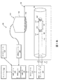
図1Aは、本開示のいくつかの実施形態による、例示的な血管内システム100の図式の概略図である。システム100は、血管内デバイス110と、撮像デバイス190と、処理システム130と、ディスプレイ160とを備える。システム100は、インターフェースモジュール120と、圧力コンソール112と、超音波コンソール192と、心電計(ECG)コンソール102とをも備える。システム100は、身体部分内の血管80中の脈波伝播速度(PWV)決定を実行するように構成される。血管内システム100は、PWVが処置目的のための患者層別化のために使用されるという点で、層別化システムと呼ばれることがある。例えば、腎動脈中のPWV決定は、患者が腎動脈除神経に好適であるか及び/又は腎動脈除神経から利益を得る可能性があるかどうかを決定するために利用される。PWV決定に基づいて、血管内システム100は、1人又は複数の患者を、腎除神経の予測された治療利益の様々な程度にそれぞれ関連するグループに分類するために使用される。任意の好適な数のグループ又はカテゴリーが企図される。例えば、グループは、それぞれ、PWVに基づいて腎除神経からの治療利益の低い可能性、中程度の可能性、及び/又は高い可能性をもつ患者のためのグループを含む。層別化又は分類に基づいて、システム100は、1人又は複数の患者が腎除神経のための好適な候補である程度を推奨することができる。
FIG. 1A is a schematic diagram of an
血管80は、流体で満たされた又は囲まれた構造を表し、自然及び人工の両方である。血管80は、患者の身体内にある。血管80は、心臓血管構造、末梢血管構造、神経血管構造、腎臓血管構造を含む、患者の血管系の動脈又は静脈としての血管、及び/又は身体内の任意の他の好適なルーメンである。例えば、デバイス110は、限定はしないが、肝臓、心臓、腎臓、胆嚢、膵臓、肺を含む器官と、導管と、腸と、脳、硬膜嚢、脊髄及び末梢神経を含む神経系構造と、尿路と、心臓内の弁、心臓の室又は他の部分、及び/或いは身体の他の系とを含む、任意の数の解剖学的ロケーション及び組織タイプを検査するために使用される。自然構造に加えて、デバイス110は、限定はしないが、心臓弁、ステント、シャント、フィルタ及び他のデバイスなどの人工構造を検査するために使用される。血管80の壁は、血管80内を流体が通って流れるルーメン82を画定する。
血管80は、身体部分180内に位置する。血管80が腎動脈であるとき、患者身体部分180は、腹部、腰部領域、及び/又は胸部領域を含む。概して、血管80は、頭、首、胸、腹部、腕、鼠径部、脚などを含む、患者身体の任意の部分180内に位置する。
The
血管内デバイス110は、カテーテル、ガイドワイヤ、又はガイドカテーテル、及び/或いは血管80のルーメン82に挿入されるためにサイズ決定及び成形された他の長く、薄い、可撓性の構造である。その関連で、血管内デバイス110は、遠位部分172及び近位部分174を有する可撓性細長部材170を備える。血管内デバイス110の図示された実施形態は、血管内デバイス110の外径を画定する、円形断面輪郭をもつ円筒形輪郭を有する。他の事例では、血管内デバイスの全部又は一部分が、他の幾何学的断面輪郭(例えば、卵形、矩形、正方形、楕円など)又は非幾何学的断面輪郭を有する。いくつかの実施形態では、血管内デバイス110は、他の計器を受容及び/又は案内するためにそれの長さの全部又は一部分に沿って延びるルーメンを備えても備えなくてもよい。血管内デバイス110がルーメンを備える場合、ルーメンは、デバイス110の断面輪郭の中心と合わせられるか又はずらされる。
血管内デバイス110、又はそれの様々な構成要素は、非限定的な例として、プラスチック、ポリテトラフルオロエチレン(PTFE)、ポリエーテルブロックアミド(PEBAX)、熱可塑性物質、ポリイミド、シリコーン、エラストマー、ステンレス鋼、チタン、ニチノールなどの形状記憶合金など、金属、及び/又は他の生物学的に適合性がある材料を含む、様々な材料から製造される。加えて、血管内デバイスは、カテーテル、ガイドワイヤ、カテーテル及びガイドワイヤの組合せなどを含む、様々な長さ、直径、寸法、及び形状で製造される。例えば、いくつかの実施形態では、可撓性細長部材170は、約115cm〜155cmに及ぶ長さを有するように製造される。特定の一実施形態では、可撓性細長部材170は、約135cmの長さを有するように製造される。いくつかの実施形態では、可撓性細長部材170は、約0.35mm〜2.67mm(1Fr〜8Fr)に及ぶ外側横断寸法又は直径を有するように製造される。一実施形態では、可撓性細長部材170は、2mm(6Fr)以下の横断寸法を有するように製造され、それにより、血管内デバイス110が患者の腎臓血管構造への挿入のために構成されることを可能にする。これらの例は、説明の目的で与えられるにすぎず、限定するものではない。概して、血管内デバイス110は、血管80の圧力が血管80内から監視されるように、血管内デバイス110が患者の血管構造(又は(1つ又は複数の)他の内部ルーメン)内で移動されるようにサイズ決定及び成形される。
The
図1Aの実施形態では、血管内デバイス110は、可撓性細長部材170の遠位部分172に配設された単一のセンサー204を備える。他の実施形態では、図1Bの血管内システム200など、血管内デバイス110は、可撓性細長部材170の遠位部分172に配設された2つのセンサー202、204を備える。センサー202、204は、可撓性細長部材170の長さに沿って、互いから、知られている距離D1をおいて配設される。いくつかの実施形態では、距離D1は、約0.5cmから約10cmの間の固定距離である。いくつかの実施形態では、距離D1は、約0.5cmから約2cmの間である。いくつかの実施形態では、血圧測定は、管を通過する脈波を識別するために使用される。
In the embodiment of FIG. 1A,
センサー202、204は、血管80内の状態に関するデータを収集し、特に、血管80内の圧力を監視するように構成される。更に、センサー202、204は、血管80内のセンサー202、204のロケーションにおける流体(例えば、血液)の圧力を周期的に測定する。一例では、センサー202、204は、容量性圧力センサー、又は特に、容量性MEMS圧力センサーである。別の例では、センサー202、204はピエゾ抵抗圧力センサーである。また別の例では、センサー202、204は光学圧力センサーである。いくつかの事例では、センサー202、204は、それぞれ、Volcano Corporationから入手可能な、PrimeWire PRESTIGE(登録商標)圧力ガイドワイヤ、PrimeWire(登録商標)圧力ガイドワイヤ、並びにComboWire(登録商標)XT圧力及びフローガイドワイヤなど、市販の圧力監視要素において見つかるものと同様の又は同じ構成要素を備える。血管内デバイス110は、センサー202、204によって取得された血管内データが、血管内デバイス110によって送信され、処理システム130において受信されるように、インターフェースモジュール120、圧力コンソール112、及び/又は処理システム130と通信している。
The
一実施形態では、センサー202、204は、血管内デバイス110の遠位部分の周りに円周方向に配設される。別の実施形態では、センサー202、204は、血管内デバイス110の本体内に含まれている。他の実施形態では、センサー202、204は、血管80内の流体がセンサー202、204に圧力を加えることを可能にする様式で、血管内デバイス110にわたって長手方向及び/又は径方向に配設される。センサー202、204は、1つ又は複数のトランスデューサ要素を備える。センサー202及び/又はセンサー204は、血管内デバイス110の長さに沿って可動であり、及び/又は血管内デバイス110の長さに沿って静止位置に固定される。センサー202、204は、血管内デバイス110のセンサーの平面アレイ又はさもなければ好適に成形されたアレイの一部である。いくつかの実施形態では、可撓性細長部材170の外径は、センサー202、204の外径に等しいか又はそれよりも大きい。いくつかの実施形態では、可撓性細長部材170及びセンサー202、204の外径は、約1mmに等しいか又はそれよりも小さく、これは、血管80内の圧力測定に対する血管内デバイス110の影響を最小限に抑えるのを助ける。特に、腎動脈は、概して、約5mmの直径を有するので、血管内デバイス110の1mm外径は、管の4%未満を塞ぐ。
In one embodiment, the
いくつかの実施形態では、センサー202、204の一方又は両方が、同じ血管内デバイス110の一部でないことがある。例えば、図1Cの血管内システム250に示されているように、センサー202、204は、別個の血管内デバイス110、113に結合される。その関連で、血管内デバイス113は、可撓性細長部材171を備える。センサー202は、可撓性細長部材171の遠位部分に結合される。センサー204は、血管内デバイス110の可撓性細長部材170の遠位部分に結合される。いくつかの実施形態では、血管内デバイス113はカテーテルであり、血管内デバイス110は、センサー204が、血管80内でセンサー202の遠位に配置されるように、カテーテルのルーメンを通って延びたガイドワイヤである。そのような構成では、センサー202は、近位圧力測定値を取得するように構成され、センサー204は、遠位圧力測定値を取得するように構成される。血管内デバイス113は、圧力コンソール112及び/又はインターフェースモジュール123を介して処理システム130と通信している。
In some embodiments, one or both of the
図1A、図1B、及び図1Cを参照すると、撮像デバイス190は、血管80に関連する撮像データを取得するように構成される。撮像デバイス190は、いくつかの実施形態では、超音波撮像デバイスである。その関連で、撮像デバイス190は、超音波トランスデューサ196を有するプローブ194を備えることができる。トランスデューサ196は、単一のトランスデューサ要素、トランスデューサ要素のアレイ、及び/又はトランスデューサ要素の他の好適な配列である。いくつかの事例では、プローブ194は、臨床医など、ユーザによって手でつかむためにサイズ決定及び成形される。図3A及び図3Bに示されているものなど、いくつかの実施形態では、プローブ194は、ホルダー210に結合され、及び/又はホルダー210内に配設される。本明細書で説明されるように、ホルダー210は、トランスデューサ196が血管80から所望の様式で撮像データを取得するための位置及び/又は配向に、プローブ194を移動するように構成される。
Referring to FIGS. 1A, 1B, and 1C, the
概して、図3A及び図3Bに示されているように、トランスデューサ196は、身体部分180内の血管80及び/又は周囲の解剖学的構造の画像を作成するために、超音波エネルギー198を放出するように構成される。超音波198は、(血管壁の様々な層など)組織構造、赤血球、及び他の関心特徴に起因する不連続性によって、部分的に反射される。反射波からのエコーが、トランスデューサによって受信され、超音波コンソール192及び/又は処理システム130に伝えられる。超音波コンソール192及び/又は処理システム130は、超音波エコーに関連する音響インピーダンスに基づいて血管80及び/又は身体部分180の画像を生成するために、受信された超音波エコーを処理する。画像は、管の2次元断面画像又は3次元画像である。撮像デバイス190及び/又は超音波コンソール192は、それぞれ、Koninklijke Philips N.V.から入手可能なEPIQ、Affiniti、及び/又はCX50超音波システムなど、市販の超音波撮像要素において見つかる特徴と同様の又は同じ特徴を含む。
In general, as shown in FIGS. 3A and 3B, the
プローブ194及び/又はトランスデューサ196は、身体部分180の外部に配置される。ただし、プローブ194及び/又はトランスデューサ196は、血管80を含む身体部分180に近接して及び/又はそれと接触して配置される。臨床医及び/又はホルダー210は、解剖学的構造が弾性的に押しつけられるように、トランスデューサ196を身体部分180に接触する。超音波画像に示された解剖学的構造のビューは、プローブ194の位置及び配向に依存する。センサー202、204を含む、血管80の撮像データを取得するために、プローブ194は、トランスデューサ196が超音波を放出し、血管80の適切な部分から超音波エコーを受信するように、臨床医によって手動で及び/又はホルダー210によって自動的に適切に配置される。
The
撮像デバイス190によって取得された撮像データは、速度データ及び/又はルーメンデータを含むことができる。この点について、血管80は、ルーメン82並びに血管80内の流体を画定する血管壁など、解剖学的構造を含む。血管80内の流体は、撮像デバイス190に対して移動している。撮像デバイス190によって取得されたルーメンデータは、血管壁を含む、比較的静止した解剖学的構造を表す。超音波コンソール192及び/又は処理システム130は、受信された超音波エコーの変動する音響インピーダンスに対応する解剖学的構造のBモード(輝度モード)撮像を生成する。ルーメンデータは、血管80に関連する直径、断面積、ボリューム、及び/又は他の幾何学的データを評価するために使用される。撮像デバイス190によって取得された速度データは、血管80内の流体フローの大きさ及び/又は方向を表す。その関連で、速度データは、(例えば、血管80の画像中の各ピクセルについて)流体フローの局所的大きさ/方向を示す。ドップラーフロー及びベクトルフローを含む、速度データを決定するための様々な技法が存在する。ドップラーフロー撮像では、トランスデューサ196によって取得された超音波エネルギーに関連する周波数シフトが、流体フローの速度及び方向を決定するために計算及び使用される。ドップラーフロー撮像は、流体フローに対するトランスデューサ196の角度に依存し、1次元フロー情報に限定される。ベクトルフロー撮像は、流体フローの角度非依存視覚化が与えられるように、トランスデューサ196によって取得された超音波データから3次元フロー情報を導出する。
The imaging data acquired by the
ルーメンデータ及び速度データは、しばしば、例えば図4に示されているように、ディスプレイ160上の表示のために組み合わせられる。ドップラーフローデータ302は、説明図又は凡例306で与えられるように、流体フローの変動する大きさ及び方向を示す異なる色として示される。ベクトルフローデータは、変動する大きさ及び方向を有する矢印304などを用いて、記号的に示される。ドップラーフロー及び/又はベクトルフローデータは、管ジオメトリを示す血管80のBモード画像上にオーバーレイされる、速度マップとして参照される。
Lumen data and velocity data are often combined for display on
再び図1A、図1B、及び図1Cを参照すると、システム100、200、及び250は、患者上に配置された電極から心電計(ECG)データを取得するように構成されたECGコンソールを備えることができる。ECG信号は、心臓の電気的活動を表し、患者の心周期及び/又はそれの部分を識別するために使用され得る。本明細書でより詳細に説明されるように、処理システム130は、撮像デバイス190によって取得された速度データ及び/又は血管内デバイス110によって取得された圧力データが、心周期全体及び/又はそれの一部分にわたって取得されるかどうかに基づいて、PWVを計算するために異なる式を利用することができる。ECGデータは、心周期の部分の中でも、前、現在、及び次の(1つ又は複数の)心周期の始まり及び終わり、収縮期の始まり及び終わり、拡張期の始まり及び終わりを識別するために使用され得る。概して、(限定はしないが、P波の開始、P波のピーク、P波の終了、PR間隔、PRセグメント、QRS群の始まり、R波の開始、R波のピーク、R波の終了、QRS群の終了(J点)、STセグメント、T波の開始、T波のピーク、及びT波の終了を含む)ECG信号の1つ又は複数の識別可能な特徴が、心周期の関連部分を選択するために利用され得る。ECGコンソール102は、Koninklijke Philips N.V.から入手可能なPageWriter心拍動記録器システムなどの市販のECG要素において見つかる特徴と同様の又は同じ特徴を含む。
Referring again to FIGS. 1A, 1B, and 1C,
他の実施形態では、血管内デバイス110によって取得された圧力データは、心周期の関連部分を識別するために使用される。その関連で、圧力データは、ECGデータの代わりに、又はそれに加えて使用される。例えば、取得された圧力データを表す圧力波形の最小値、最大値、勾配、及び/又は他の値は、(1つ又は複数の)心周期並びに/或いは、収縮期及び拡張期を含む、それの部分を示す。
In other embodiments, pressure data acquired by
処理システム130は、血管内デバイス110と通信している。例えば、処理システム130は、インターフェースモジュール120及び/又は圧力コンソール112を通して、センサー202及び/又はセンサー204を備える、血管内デバイス110と通信する。プロセッサ140は、コマンドを送り、血管内デバイス110から応答を受信する。いくつかの実装形態では、プロセッサ140は、センサー202、204によって血管80内の圧力を監視することを制御する。特に、プロセッサ140は、特定の時間における圧力を測定するために、センサー202、204のアクティブ化を誘発するように構成される。センサー202、204からのデータが、処理システム130の処理エンジン140によって受信される。他の実施形態では、処理エンジン140は、血管内デバイス110から物理的に分離されるが、(例えば、ワイヤレス通信を介して)血管内デバイス110と通信している。いくつかの実施形態では、処理エンジン140は、センサー202、204を制御するように構成される。同様に、2つの血管内デバイスを備える実施形態(図1C)では、処理システム130は、インターフェースモジュール123及び/又は圧力コンソール112を通して血管内デバイス113と通信する。
The
同様に、処理システム130は、撮像デバイス190と通信している。例えば、処理システム130は、トランスデューサ196を備える、撮像デバイス190と通信する。プロセッサ140は、コマンドを送り、撮像デバイス190から応答を受信する。いくつかの実装形態では、プロセッサ140は、トランスデューサ196によって血管80内の速度及び/又は管ジオメトリを監視することを制御する。特に、プロセッサ140は、特定の時間における速度データ及び/又はルーメンデータを取得するために、トランスデューサ196のアクティブ化を誘発するように構成される。トランスデューサ196からのデータが、処理システム130の処理エンジン140によって受信される。他の実施形態では、処理エンジン140は、血管内デバイス110から物理的に分離されるが、(例えば、ワイヤレス通信を介して)撮像デバイス190と通信している。いくつかの実施形態では、処理エンジン140は、トランスデューサ196を制御するように構成される。
Similarly,
プロセッサ140は、センサーに指令すること並びにデータを受信及び処理することなど、論理関数を実行することが可能な電源ピン、入力ピン、及び出力ピンをもつ集積回路を備える。プロセッサ140は、マイクロプロセッサ、コントローラ、デジタル信号プロセッサ(DSP)、特定用途向け集積回路(ASIC)、フィールドプログラマブルゲートアレイ(FPGA)、或いは同等の個別又は集積論理回路のうちの任意の1つ又は複数を含む。いくつかの例では、プロセッサ140は、1つ又は複数のマイクロプロセッサ、1つ又は複数のコントローラ、1つ又は複数のDSP、1つ又は複数のASIC、或いは1つ又は複数のFPGA、並びに他の個別又は集積論理回路の任意の組合せなど、複数の構成要素を含む。本明細書でプロセッサ140にあるとされる機能は、ソフトウェア、ファームウェア、ハードウェア又はそれらの任意の組合せとして具現される。 The processor 140 comprises an integrated circuit having power supply pins, input pins, and output pins capable of performing logical functions such as commanding sensors and receiving and processing data. Processor 140 may be any one or more of a microprocessor, controller, digital signal processor (DSP), application specific integrated circuit (ASIC), field programmable gate array (FPGA), or equivalent discrete or integrated logic circuit. including. In some examples, the processor 140 is one or more microprocessors, one or more controllers, one or more DSPs, one or more ASICs, or one or more FPGAs, as well as other It includes multiple components, such as any combination of discrete or integrated logic circuits. The functions resident in processor 140 herein may be embodied in software, firmware, hardware, or any combination thereof.
処理システム130は、1つ又は複数のプロセッサ140、或いは機能の中でも、本明細書で説明される脈波伝播速度決定方法を実装するために、プログラマブルコード命令を実行するプログラマブルプロセッサユニットを備える。処理システム130は、コンピュータ及び/又は他のタイプのプロセッサベースデバイス内に組み込まれる。例えば、処理システム130は、コンソール、タブレット、ラップトップ、ハンドヘルドデバイス、或いは血管内デバイス110の動作を制御又は指示するための制御信号を生成するために使用される他のコントローラの一部である。いくつかの実施形態では、ユーザは、血管内デバイス110及び/又は撮像デバイス190の動作をプログラム又は指示し、並びに/或いはディスプレイ160の態様を制御する。いくつかの実施形態では、処理システム130は、ワイヤード及び/又はワイヤレス通信技法を介して、(例えば、インターフェースモジュール120なしに)血管内デバイス110及び/又は撮像デバイス190と直接通信している。
The
処理システム130は、インターフェースモジュール120及び/又は圧力コンソール112を介して血管内デバイス110と通信している。インターフェースモジュール120は、処理システム130から血管内デバイス110への制御信号の送信、並びに血管内デバイス110から処理システム130への圧力データの送信を容易にするように構成された回路を備えることができる。いくつかの実施形態では、インターフェースモジュール120は、電力をセンサー202、204に供給することができる。いくつかの実施形態では、インターフェースモジュールは、処理システム130への送信より前に、圧力データの信号調整及び/又は前処理を実行することができる。
The
圧力コンソール112は、特に血管内デバイス110に関連する処理システムを表す。その関連で、圧力コンソール112は、処理システム130の処理エンジン140及び処理メモリ150と同様の処理エンジン及び処理メモリを備える。いくつかの事例では、圧力コンソール112は、血管80内の流体フローに関連する圧力を測定するために、センサー202、204によって取得された圧力データを処理する。処理されたデータは、圧力データ及び撮像データに基づくPWVの計算を含む、撮像デバイス190によって取得された撮像データと組み合わせた更なる処理のために、圧力コンソール112によって処理システム130に送信される。いくつかの事例では、圧力コンソール112及び/又はインターフェースモジュール120は、省略され、血管内デバイス110は、処理システム130と直接通信している。
処理システム130は、超音波コンソール192を介して撮像デバイス190と通信している。圧力コンソール112に関して同様に説明されたように、超音波コンソール192は、特に撮像デバイス190に関連する処理システムを表す。その関連で、超音波コンソール192は、処理システム130の処理エンジン140及び処理メモリ150と同様の処理エンジン及び処理メモリを備える。いくつかの事例では、超音波コンソール192は、血管80内の管ジオメトリ及び/又は流体流速を表す画像を生成するために、トランスデューサ196によって取得された速度データ及び/又はルーメンデータを含む、撮像データを処理する。処理されたデータは、圧力データ及び撮像データに基づくPWVの計算を含む、血管内デバイス110によって取得された圧力データと組み合わせた更なる処理のために、超音波コンソール192によって処理システム130に送信される。いくつかの事例では、超音波コンソール192は、省略され、撮像デバイス190は、処理システム130と直接通信している。
The
その上、いくつかの実施形態では、圧力コンソール112、インターフェースモジュール120、超音波コンソール192、及び/又は処理システム130は、連結され、並びに/或いは同じシステム、ユニット、シャーシ、又はモジュールの一部である。圧力コンソール112、インターフェースモジュール120、超音波コンソール192、及び/又は処理システム130は一緒に、ディスプレイ160上の画像としての表示のために、撮像デバイス190によって取得された撮像データ及び血管内デバイス110によって取得された圧力データをアセンブルし、処理し、レンダリングする。例えば、様々な実施形態では、インターフェースモジュール120及び/又は処理システム130は、センサー202、204を構成するための制御信号を生成し、センサー202、204をアクティブ化するための信号を生成し、圧力データの計算を実行し、圧力データの増幅、フィルタ処理、及び/又はアグリゲートを実行し、表示のための画像として圧力データをフォーマットする。同様に、様々な実施形態では、処理システム130は、トランスデューサ196を構成するための制御信号を生成し、トランスデューサ196をアクティブ化するための信号を生成し、撮像データの計算を実行し、撮像データの増幅、フィルタ処理、及び/又はアグリゲートを実行し、表示のための画像として撮像データをフォーマットする。これらのタスクなどの割振りは、様々なやり方で、圧力コンソール112、インターフェースモジュール120、超音波コンソール192、及び/又は処理システム130間で分散される。
Moreover, in some embodiments, the
処理システム130は、血管内デバイス110による圧力データ及び撮像デバイス190による超音波データの収集を同期させるように構成される。いくつかの事例では、インターフェースモジュール120、圧力コンソール112、及び/又は超音波コンソール192、並びに処理システム130は、タイマーを備えることができる。インターフェースモジュール120、圧力コンソール112、及び/又は超音波コンソール192に通信することによって、処理システム130は、インターフェースモジュール120、圧力コンソール112、及び/又は超音波コンソール192のタイマーをプロセッサタイマーと同期させることができる。更に、インターフェースモジュール120、圧力コンソール112、及び/又は超音波コンソール192は、センサー202、204及び撮像デバイス190から受信された信号のサンプリングを行うことができ、サンプリングされたデータにタイムスタンプを含め、次いで、タイムスタンプを付けられたサンプリングされたデータを処理システム130に送ることができ、したがって、処理システム130によって受信された、血管内の圧力を監視することに関連する圧力データ及び血管内の速度を監視することに関連する速度データは、タイムスタンプを付けられ、処理システム130は、受信されたタイムスタンプに基づいてデータを同期させることができる。
The
代替的に、インターフェースモジュール120、圧力コンソール112、及び/又は超音波コンソール192の代わりに、センサー202、204、及び撮像デバイス190が、サンプリングを実行し、サンプリングされたデータを処理システム130に送ることができる。血管内デバイス110は、センサー202、204のための1つ又は複数のタイマーを備えることができ、撮像デバイス190はタイマーを備えることができる。処理システム130は、血管内デバイス110及び撮像デバイス190に通信することによって、センサー202、204及びトランスデューサ196によるデータ収集をプロセッサタイマーと同期させることができる。したがって、撮像デバイス190及びセンサー202、204によって取得されたデータは、タイムスタンプを含むことができる。インターフェースモジュール120、圧力コンソール112、及び/又は超音波コンソール192は、タイムスタンプを使用して、取得されたデータを同期させ、次いで、データを処理システム130に送ることができる。別の例では、インターフェースモジュール120、圧力コンソール112、及び/又は超音波コンソール192は、センサー202、204及び撮像デバイス190によって取得されたタイムスタンプを付けられたデータを、処理システム130に送ることができる。処理システム130は、受信されたタイムスタンプに基づいてデータを同期させることができる。
Alternatively, instead of the
いくつかの事例では、ECGコンソール102によって取得されたECGデータが、センサー202、204による圧力データ及び撮像デバイス190による撮像データの収集を同期させるために使用され得る。例えば、処理システム130は、心周期中の同じ時間においてデータを同時にサンプリングするために、制御信号をセンサー202、204及び撮像デバイス190に与えることができる。データを同時にサンプリングするための心周期の間の時点を決定するために、ECGデータの1つ又は複数の特徴が使用される。
In some cases, ECG data acquired by the
いくつかの事例では、センサー202、204及び撮像デバイス190は、異なるレートでデータを取得する。したがって、処理システム130は、データをサンプリングするための制御信号送信をオフセットすることによって、圧力データの獲得と撮像データの獲得とを整合させるように構成される。例えば、センサー202、204が撮像デバイス190よりも高い頻度でデータをサンプリングする場合、処理システム130は、制御信号をセンサー202、204に送信する前に、制御信号を撮像デバイス190に送信することができる。このようにすると、撮像デバイス190は、撮像データを取得するために、センサー202、204が圧力データを取得するために有する時間よりも比較的多い時間を有するので、撮像データと圧力データとは同時に取得され得る。処理システム130は、撮像デバイス190及びセンサー202、204へのアクティブ化信号における任意の必要なオフセットを決定するための較正手順を実施する。
In some cases, the
いくつかの実施形態では、処理システム130は、センサーによって取得された圧力データ及び撮像デバイス190によって取得された速度/撮像データに基づいて、PWVを決定するように構成される。概して、PWVは、血管80の伸展性によって決定される血管80内の圧力/流量波の伝搬を指す。本明細書で説明されるように、撮像デバイス190によって取得された速度データは、血管内の血液の速度の局所的、瞬間的測定値である。したがって、血管内デバイス110によって取得された圧力データとともに、撮像デバイス190によって取得された速度データは、PWVを計算するために使用される。PWVを決定するこの方法は、特に、腎動脈など、比較的短い管にとって有利である。
In some embodiments, the
本明細書で説明されるように、圧力データ及び速度データは、両方とも同時に取得され、血管80の同じエリアにおいて取得され得る。処理システム130は、PWVを計算するために、血管内の圧力と速度との間の様々な数学的関係、並びに他の要因を利用することができる。PWVを決定するための1つの方法は、心周期の無反射期間(例えば、心収縮初期)中に「ウォーターハンマー(water hammer)」式を利用することによるものである。

処理システム130は、圧力データ及び/又は速度データが心周期全体にわたって取得されるのかそれの一部分にわたって取得されるのかに基づいて、適切な数学的関係を選択することができる。その関連で、圧力データ及び/又は速度データは、ECGデータに基づいてゲート(gate)される。したがって、PWVは、ECG信号の識別可能な特徴を使用して決定された、心収縮初期中に取得された圧力データ及び速度データの部分のみを用いて上記の式(1)を使用して計算される。同様に、1つ又は複数の心周期中の圧力データ及び速度データの関連部分が、ECG信号を使用して識別され、式(2)を用いてPWVを計算するために使用され得る。いくつかの事例では、圧力データ及び速度データをゲートするために、ECGデータに加えて又はそれの代わりに、圧力波形の特徴(例えば、最大値、最小値、勾配など)が利用される。いくつかの事例では、ユーザは、PWVを計算するための所望の数学的関係を選択するためにユーザ入力を与え、処理システム130は、それに応じて、圧力データ及び速度データの収集を指示することができる。
The
処理システム130は、更に、血管内デバイス110、センサー202、204、及び/又は撮像デバイス190の動きを監視するように構成される。その関連で、センサー202、204及び/又は撮像デバイス190は、しきい値量を越えて移動し、これは、移動中に収集されたデータをPWV計算にとって信頼できないものにする。例えば、患者が血管内デバイス110及び/又は撮像デバイス190を不意に移動し、或いは臨床医がそれらを非意図的に移動する。そのような事例では、処理システム130は、PWVの決定を保留する。このようにして、信頼できるPWV計算のみが、治療推奨を行うために、臨床医のために表示され及び/又は処理システム130によって利用される。
The
様々な周辺デバイスが、処理システム130の入力及び出力機能を可能にし、又は改善する。そのような周辺デバイスは、必ずしも限定されるとは限らないが、(マウス、ジョイスティック、キーボードなど)標準入力デバイス、(プリンタ、スピーカー、プロジェクタ、グラフィカルディスプレイスクリーンなど)標準出力デバイス、CD−ROMドライブ、フラッシュドライブ、ネットワーク接続、並びに処理システム130と、システム100、システム200及び/又はシステム250の他の構成要素との間の電気的接続を含む。非限定的な例として、処理システム130は、獲得された圧力データ、撮像データ、PWV計算、及び/又はそれらの組合せを表すディスプレイ160上の画像を生成するために、血管内デバイス110及び/又は撮像デバイス190からの信号を操作する。いくつかの事例では、ディスプレイ160は、タッチスクリーンディスプレイである。また、そのような周辺デバイスは、血管内デバイス110、撮像デバイス190、及び/又は処理システム130の一般的動作を可能にするためのプロセッサ命令を含んでいるソフトウェアをダウンロードするために使用され、並びに、例えば、血管内デバイス110及び/又は撮像デバイス190に結合された任意の補助デバイスの動作を制御するための動作を実行するためのソフトウェア実装プログラムをダウンロードするために使用される。いくつかの実施形態では、処理システム130は、広範囲の集中型又はリモート分散型データ処理方式において採用される複数の処理ユニットを含む。
Various peripheral devices enable or improve the input and output functions of
メモリ150は、例えば、読取り専用メモリ、ランダムアクセスメモリ、FRAM(登録商標)、又はNANDフラッシュメモリなど、半導体メモリである。メモリ150は、プロセッサ140がメモリ150に書き込み、それから読み取るように、プロセッサ140とインターフェースする。例えば、プロセッサ140は、血管内デバイス110、インターフェースモジュール120、圧力コンソール112、撮像デバイス190、及び/又は超音波コンソール192からデータを受信し、そのデータをメモリ150に書き込むように構成される。このようにして、一連のデータ読取値がメモリ150に記憶される。プロセッサ140は、メモリ150を消去又は上書きすること、メモリ150がいつ一杯であるかを検出すること、及び半導体メモリを管理することに関連する他の一般的な機能など、他の基本的なメモリ機能を実行することが可能である。
The
図2は、ヒトの腎臓解剖学的構造内に配設された図1の血管内デバイス110を示す。ヒトの腎臓解剖学的構造は、右及び左腎動脈81によって含酸素血液を供給される腎臓10を含み、右及び左腎動脈81は、腎臓口部92において腹大動脈90から分岐して、腎臓10の門部95に入る。腹大動脈90は、腎動脈81を心臓(図示せず)に接続する。脱酸素血液が、腎静脈101及び下大静脈111を介して腎臓10から心臓に流れる。詳細には、血管内デバイス110の可撓性細長部材170は、腹大動脈を通って左腎動脈81中に延びるように示されている。代替実施形態では、血管内デバイス110は、同様に下腎血管(inferior renal vessel)115を通って進むようにサイズ決定及び構成される。詳細には、血管内デバイス110は、腹大動脈を通って左腎動脈81中に延びるように示されている。代替実施形態では、カテーテルは、同様に下腎血管115を通って進むようにサイズ決定及び構成される。いくつかの例では、右又は左腎動脈81は、図1a、図1b、及び図1cに関して説明された血管80である。
2 shows the
左及び右腎神経叢又は神経121は、それぞれ、左及び右腎動脈81を囲む。解剖学的に、腎神経121は、腎動脈81を囲む外膜組織内に1つ又は複数の神経叢を形成する。本開示では、腎神経は、腎臓10に及び/又はそれから神経信号を伝える、個々の神経又は神経叢及び神経節として定義され、解剖学的に、腎動脈81の表面、腎動脈81が大動脈90から分岐する腹大動脈90の部分、及び/又は腎動脈81の下分岐に位置する。神経叢121に寄与する神経線維は、腹腔神経節、最下内臓神経、腎皮質(corticorenal)神経節、及び大動脈神経叢から生じる。腎神経121は、それぞれの腎動脈と密接に関連してそれぞれの腎臓10の実体中に延びる。神経は、腎臓10の管、糸球体、及び尿細管への腎動脈の分岐に伴って分散される。各腎神経121は、概して、腎臓の門部95のエリアにおいて各それぞれの腎臓10に入るが、腎動脈81又は腎動脈81の分岐が腎臓10に入るロケーションを含む、任意のロケーションにおいて腎臓10に入る。
The left and right renal plexuses or
適正な腎機能は、高血圧症状を回避するために、心臓血管ホメオスタシスの維持にとって不可欠である。ナトリウムの排泄は、適切な細胞外流体ボリューム及び血液ボリュームを維持し、動脈圧に対するこれらのボリュームの影響を最終的に制御することの鍵である。安定状態の症状の下で、動脈圧は、尿排出量と水及びナトリウム摂取量との間で平衡を生じる圧力レベルまで上昇する。異常な腎機能により、腎神経121を通した腎臓の交感神経過剰刺激とともに発生する、過大な腎臓ナトリウム及び水保持が生じた場合、動脈圧は、ナトリウム排出量を摂取量に等しく維持するためのレベルまで増加する。高血圧患者では、ナトリウム摂取量とナトリウム排出量との間の平衡は、部分的に、腎神経121を通した腎臓の交感神経刺激の結果として、高い動脈圧という犠牲を払って達成される。腎除神経は、腎臓10の遠心性及び求心性交感神経活動を遮断又は抑制することによって、高血圧の症状及び後遺症を緩和するのを助ける。
Proper renal function is essential for maintaining cardiovascular homeostasis to avoid hypertensive symptoms. Na excretion is key to maintaining proper extracellular fluid and blood volumes and ultimately controlling the effect of these volumes on arterial pressure. Under steady-state conditions, arterial pressure rises to a pressure level that creates a balance between urine output and water and sodium intake. When abnormal renal function results in excessive renal sodium and water retention, which occurs with sympathetic hyperstimulation of the kidney through the
図3A及び図3Bは、撮像デバイス190を介した撮像データ及び血管内デバイス110を介した圧力データを取得するための血管内システム200(図1B)の動作の態様を示す。図3A及び図3Bは、血管内システム200の構成要素を使用して説明されるが、血管内システム100及び250(図1A及び図1C)の構成要素を使用して、撮像データ及び圧力データが同様に取得され得ることを理解されたい。
3A and 3B illustrate aspects of operation of intravascular system 200 (FIG. 1B) for acquiring imaging data via
血液など、流体が、矢印220によって示された例示的な方向に血管80内を流れる。血管内デバイス110は、流体が圧力センサー202、204を囲み、それらに圧力を加えるように、血管内に配置される。センサー202、204によって測定された圧力を表す電気信号が、圧力データのグラフィカル表現を生成すること及び/又はPWVを計算することにおいて使用するために、圧力コンソール112及び/又は処理システム130に送信される。圧力データのグラフィカル表現は、圧力波形、圧力の数値などを含むことができる。
A fluid, such as blood, flows within
撮像デバイス190のトランスデューサ196は、超音波エネルギー198を放出し、超音波エネルギー198は、血管80、血管80内の流体、及び/又は患者身体180内の他の解剖学的構造によって反射される。反射された超音波からの超音波エコーは、トランスデューサによって受信される。撮像データ又は超音波データを表す電気信号が、超音波データのグラフィカル表現を生成すること及び/又はPWVを計算することにおいて使用するために、超音波コンソール及び/又は処理システム130に送信される。超音波データのグラフィカル表現は、Bモード画像及び速度マップ、速度の数値などを含むことができる。
The
トランスデューサ196は、血管80と整合されている間に超音波データを取得するように構成される。その関連で、トランスデューサ196は、超音波データが、圧力センサー202、204を含む血管内デバイス110の構成要素を含むように、血管80と整合される。すなわち、超音波データから生成されたBモード/フロー画像は、センサー202、204が配置されている血管80の部分を含む。このようにして、撮像デバイス190によって取得された速度データは、センサー202、204が位置する血管80の同じエリア内の流体に関連する。したがって、速度データ及び圧力データは、同時に、血管内の同じロケーションから取得される。
図3A及び図3Bは、撮像デバイス190が、撮像デバイス190を移動するように構成されたホルダー210内に配置されることを示す。ホルダー210は、プローブ194に適応するようにサイズ決定及び成形された任意の好適な機械的構造である。ホルダー210は、血管80が圧力センサー202、204を含んでいる部分内の撮像データを含む、所望の撮像データが取得されるように、血管80に対してプローブ194を機械的に配置及び/又は配向するように構成される。ホルダー210は、1つ又は複数のアクチュエータを備え、アクチュエータは、制御信号に応答して、プローブ194を、例えば、6つの自由度(3つの回転自由度及び3つの並進自由度)で並進させ、回転し、及び/又は、場合によっては、移動する。3つの自由度が、図3A及び図3Bに示されている。例えば、撮像デバイス190は、方向212、214に並進させられ、方向216に回転され得る。他の並進/回転自由度は、図3A及び図3Bに示されていない。
3A and 3B show that the
図3Aに対して、図3Bでは、撮像デバイス190は方向216に時計回りに回転される。ホルダー210は、撮像デバイス190を移動するために制御信号をホルダー210に送信するように構成された、処理システム130と通信している。例えば、処理システム130は、血管80及び/又はセンサー202、204と整合されている間に撮像データを取得するために、撮像デバイス190を移動するために制御信号をホルダー210に送信する。いくつかの事例では、処理システム130は、撮像デバイス190が適切に配向されることを保証するために、フィードバックループを利用する。例えば、処理システム130は、血管80及びセンサー202、204がトランスデューサ196によって適切に調べられていることを保証するために、撮像デバイス190によって取得されている撮像データを周期的に評価する。ホルダー210は、血管80及びセンサー202、204が適切にビュー内にないとき、撮像デバイス190を移動する。ホルダー210は、ユーザ入力に応答して、撮像デバイス190を血管80及び/又はセンサー202、204と整合されているように自動的に調整する。図4の例示的なスクリーン表示に示されているように、ユーザは、ホルダー210及び処理システム130によって提供される自動的な位置/配向補正をオン/オフにトグルするための入力オプション330を選択することができる。
In FIG. 3B, as compared to FIG. 3A, the
再び図3A及び図3Bを参照すると、センサー202、204は、センサーがBモード/フロー画像中で見えるように、超音波に反応することができる。その関連で、センサー202、204は、血管80内の流体の周囲の領域と比較して、比較的より高い振幅をもつ超音波エコーに関連する。したがって、処理システム130は、撮像デバイス190によって取得された撮像データを使用して、血管80内のセンサー202、204のロケーションを決定及び追跡するように構成され得る。インターベンショナルツール、例えば、血管内デバイス110のセンサーを追跡する例は、その全体が参照により本明細書に組み込まれる、PCT特許出願公開第WO2011138698A1号において説明されている。更に、図4に示されているように、いくつかの事例では、処理システム130は、超音波画像300においてセンサー202、204のロケーションを強調する。血管80中のセンサー202、204のロケーションに対応する位置において、インジケータ308が画像300上にオーバーレイされる。ユーザは、例示的なスクリーン表示において入力オプション310を選択することによって、センサー追跡をオン/オフにトグルする。
Referring again to FIGS. 3A and 3B, the
再び図3A及び図3Bを参照すると、トランスデューサ196は、解剖学的構造内の平面に沿って超音波データを取得するように構成される。すなわち、トランスデューサ196は、平面に沿った断面画像が、超音波データを使用して生成され得るように、放出されたエネルギー198を平面に沿って集束させることができる。本明細書で説明されるように、処理システム130及び/又は超音波コンソール192は、撮像平面に沿って血流の速度を決定し、関連する速度マップを生成することができる。2つの例示的な平面230a、230bが、図3A及び図3Bに示されている。いくつかの事例では、処理システム130は、トランスデューサ196が、センサー202、204と整合されている間に速度データを含む超音波データを取得するように、好適な平面を自動的に選択するように構成される。図示の実施形態では、放出されたエネルギー198は、センサー202、204に比較的近い平面230aに沿って集束させられる。したがって、センサー202、204によって取得された圧力データ、及びトランスデューサ196によって取得された超音波データは、血管80の同じエリアからのものである。
Referring again to FIGS. 3A and 3B, the
処理システム130は、トランスデューサ196に関連する撮像/速度平面を選択するために、様々な要因に依拠することができる。例えば、処理システム130は、血管80のジオメトリ、血管80のBモード/フロー画像内の血管内デバイス110のロケーション、及び/又はセンサー202、204の追跡されたロケーションのうちの1つ又は複数を利用することができる。血管80のジオメトリは、取得された撮像データに基づいて、形状、直径、エリア、ボリューム、及び/又は他の量を含むことができる。管ジオメトリは、例えば、選定された撮像/速度平面が血管壁を含まないことを保証するために利用され得る。センサー202、204のロケーションは、管のBモード/フロー画像内の血管内デバイス110のロケーションから外挿される。有利には、両方のセンサー202、204のロケーションを追跡することによって、撮像デバイス190は、血管内デバイス110の全セグメント(例えば、距離D1)を視覚化することができ、したがって、血管80中の流体フローとの整合を保証するように、トランスデューサの配向及び/又は撮像平面が選択される。更に、センサー202、204は、より信頼できる様式で流速を推定するために、ドップラー角度を自動的に推定するために使用される。センサー202、204の追跡されたロケーションは、速度平面が、所望の様式で整合されることを可能にする比較的より正確な案内を提供する。図4に示されているように、ユーザは、例示的なスクリーン表示において入力オプション320を選択することによって、自動的な超音波平面選択をオン/オフにトグルする。いくつかの事例では、図示のように、処理システム130は、超音波画像300において、選択された撮像平面230cのロケーションを強調する。
The
いくつかの実施形態では、図1a、図1b、図1c、図3a、及び図3b中の血管80は、図2の管81に一致する腎血管である。処理システム130は、腎動脈中の脈波伝播速度(PWV)を決定する。処理システム130は、腎動脈中の脈波伝播速度に基づいて、腎除神経治療推奨を決定する。例えば、腎除神経から治療的に利益を得る可能性が高い患者又は可能性が低い患者が、PWVに基づいて選択される。その関連で、少なくとも腎血管中の血液のPWVに基づいて、処理システム130は、腎除神経のための患者層別化を実行することができる。
In some embodiments, the
図4は、処理システム130によってディスプレイ160に出力される例示的なスクリーン表示162を示す。スクリーン表示162は、管ジオメトリを示す超音波又はBモード画像300を含むことができる。速度マップ302及び/又はベクトルフローデータを示す矢印304は、画像300上にオーバーレイされ得る。説明図又は凡例306は、速度マップ302に示されている色を対応する速度と相関させる。撮像平面230c及び/又はセンサーインジケータ308は、画像300上に選択的にオーバーレイされる。スクリーン表示は、更に、それぞれ、センサー追跡、自動的な超音波平面選択、及び自動的な超音波配向を選択的にアクティブ化/非アクティブ化するための入力オプション310、320、330を含む。例示的な実施形態では、ディスプレイ160は、入力オプション310、320、330にタッチすること及び/又はそれをドラッグすることによってユーザ入力が与えられ得るような、タッチセンシティブモニタである。
FIG. 4 shows an
スクリーン表示162は、計算された脈波伝播速度を示す領域340をも含む。図示の実施形態では、PWVの数値が示されている。他の事例では、色分け及び/又は他のグラフィックスが、数値とともに表示される。例えば、PWVの重大度を示すために緑、黄、赤、及び/又は他の好適な色並びに模様が使用される。
The
スクリーン表示162の領域350は、処理システム130によって決定された治療推奨を含む。本明細書で説明されるように、処理システム130は、どの患者が腎除神経処置から利益を得る可能性があるかを決定するために、腎動脈内の計算されたPWVを使用することができる。図示の実施形態では、治療推奨はテキスト指示である。例えば、「不可(Poor)」、「可(Fair)」、「良(Good)」、及び/又は他の好適な言葉が、特定の患者についての治療に関連する予測された利益を伝える。他の事例では、治療推奨を表す数値のスコア、色分け、及び/又は他のグラフィックスが、ディスプレイ160に出力され得る。
図5は、脈波伝播速度を決定する方法500の流れ図である。方法500のステップは、図5に示されている順序とは異なる順序で実行され、ステップの前、ステップ中、及びステップの後に追加のステップが与えられ得、並びに/或いは、説明されるステップのうちのいくつかが他の実施形態において入れ替えられるか、又は除去され得ることを理解されたい。方法500のステップは、血管内システム100、200、及び250(図1A、図1B、及び図1C)の構成要素によって実行され得る。
FIG. 5 is a flow chart of a
ステップ505において、方法500は、血管内デバイスを血管内に配置するステップを含む。血管内デバイスは圧力センサーを備える。血管は腎動脈である。ステップ510において、方法500は、撮像デバイスを、血管を含む身体部分に近接して配置するステップを含む。撮像デバイスは、外部超音波トランスデューサを備える。ステップ505及び510は、診断/治療手順を実行する臨床医及び/又は他のユーザによって行われる。
In
ステップ515において、方法500は、血管内の流体に関連する圧力を監視するステップを含む。ステップ515は、血管内に配置された血管内デバイスを使用して実行される。ステップ520において、方法500は、血管内の流体に関連する圧力を監視するステップを含む。ステップ520は、血管を含む身体部分の外部に配置された撮像デバイスを使用して実行される。
At
ステップ525において、方法500は、圧力を監視することに関連する圧力データを受信するステップを含む。例えば、処理システムは、血管内デバイスから直接又は間接的に圧力データを受信する。いくつかの事例では、方法500は、血管内からの圧力測定値を取得するために圧力データを処理するステップを含む。
At
ステップ530において、方法500は、速度を監視することに関連する速度データを受信するステップを含む。例えば、処理システムは、撮像デバイスから直接又は間接的に速度データを受信する。いくつかの事例では、方法500は、速度データを抽出するために、撮像デバイスによって取得された撮像データを処理するステップを含む。
At
方法500は、血管に関連する及び撮像デバイスによって取得された、ルーメンデータを受信するステップをも含むことができる。その関連で、撮像データは、ルーメンデータを抽出するために処理され得る。いくつかの事例では、方法500は、処理システムが、管及び/又は速度データの視覚表示を生成し、ディスプレイに出力するステップを含む。例えば、速度マップを含む超音波又はBモード画像が表示される。
The
方法500は、圧力データ及び/又は速度データの収集を同期させることを含むことができる。方法500は、速度データ及び圧力データが血管内の同じエリアから取得されるように、撮像デバイスを配置するステップをも含む。
The
いくつかの実施形態では、撮像デバイスの超音波トランスデューサは、血管内の平面に沿って、速度データを含む超音波データを取得する。方法500は、処理システムが血管ジオメトリ及び/又は血管内デバイスのロケーションを使用して平面を決定するステップを含む。処理システムは、撮像デバイスによって取得されたルーメンデータ及び/又は速度データに基づいて、血管内の管ジオメトリ及び/又は血管内デバイスのロケーションを決定することができる。他の事例では、方法500は、血管内の圧力センサーのロケーションを決定するステップを含む。そのような事例では、平面は、血管ジオメトリ及び/又は圧力センサーのロケーションを使用して決定される。
In some embodiments, the ultrasound transducer of the imaging device acquires ultrasound data, including velocity data, along a plane within the blood vessel. The
いくつかの実施形態では、血管内デバイスは、圧力センサーと、更なる圧力センサーとを備える。方法500は、血管内の圧力センサーと更なる圧力センサーとのロケーションを決定するステップを含む。更に、方法500は、圧力センサーと更なる圧力センサーとのロケーションに基づいて、撮像デバイスが流体フローの方向に整合されている間、速度データを取得するステップを含む。その関連で、処理システムは、圧力センサーのロケーションに基づいて、流体フローの方向を決定する。更に、撮像デバイスに対する流体フローの方向の角度は、決定された速度データを自動的に補正するために使用される。
In some embodiments, the intravascular device comprises a pressure sensor and a further pressure sensor. The
いくつかの実施形態では、血管内デバイスは、撮像デバイスホルダーに結合される。方法500は、撮像デバイスを管と整合されているように移動するために、撮像デバイスに結合された撮像デバイスホルダーに制御信号を出力するステップを含む。処理システムは、撮像データを使用して血管内の血管内デバイス及び/又は圧力センサーのロケーションを識別することに基づいて、制御信号を生成し、出力する。
In some embodiments, the endovascular device is coupled to the imaging device holder.
ステップ535において、方法500は、圧力データ及び速度データに基づいて血管内の流体のPWVを決定するステップを含む。いくつかの実施形態では、PWVは、
ステップ545において、方法500は、PWVに基づいて治療推奨を決定するステップを含む。その関連で、腎動脈内のPWVは、患者における腎除神経の効果を予測する。したがって、PWVを計算することは、この治療手順がおそらく有益である患者の選択を容易にする。いくつかの事例では、臨床医は、算出されたPWV及び/又は他の患者データに基づいて、治療推奨を決定する。いくつかの実施形態では、処理システムは、治療推奨を決定するために、PWV及び/又は他の患者データを評価する。そのような事例では、ステップ550において、方法500は、治療推奨の視覚表示を出力するステップを含む。例えば、処理システムは、グラフィカル表現に関連するディスプレイデータをディスプレイデバイスに出力することができる。方法500は、PWVに基づいて、1人又は複数の患者を、腎除神経の結果としての予測された治療利益のそれぞれの程度に対応するグループに分類するステップを更に含むことができる。方法500は、処理システムが、分類するステップのグラフィカル表現をディスプレイデバイスに出力するステップをも含むことができる。
At
いくつかの実施形態では、方法500は、治療手順を実行するより前に、例えば、腎除神経を実行するより前に実行される。本方法は、患者層別化と腎除神経治療推奨を決定することとのために使用され得る、腎血管の脈波伝播速度を決定することができる。本方法は、抵抗性高血圧をもつ患者にとって有益である。腎交感神経活動は、高血圧、心不全、及び/又は慢性腎不全の症状を悪化させ特に、高血圧は、4つの機構、すなわち、(1)増加した血管抵抗、(2)増加した心拍数、1回拍出量及び拍出量、(3)血管筋欠陥、並びに/又は(4)腎臓によるナトリウム保持及びレニン分泌のいずれかによって刺激される、増加した交感神経系活動に関係付けられてきた。特にこの第4の機構に関して、腎交感神経系の刺激は、腎機能及びホメオスタシスの維持に影響を及ぼす。例えば、遠心性腎交感神経活動の増加が、増加した腎臓血管抵抗、レニン分泌、及びナトリウム保持を生じ、それらのすべては高血圧を悪化させる。
In some embodiments,
腎臓に入る電気信号(遠心性交感神経活動)と腎臓から出る電気信号(求心性交感神経活動)との両方に影響を及ぼす腎除神経は、腎臓自体の機械的活動及びホルモン活動、並びにSNSの残部の電気的活性化に影響を与える。腎臓への遠心性交感神経活動を遮断することは、流体及び塩類保持を反転(ナトリウム排泄増加及び利尿を増大)させ、それによって、心臓に対する流体ボリューム及び機械的負荷を低下させ、不適切なレニン分泌を低減し、それによって、有害なホルモンRAASカスケードが開始する前にそのカスケードを停止させることによって、高血圧及び関係する心臓血管疾患を緩和する。 Renal denervation, which affects both the electrical signals entering the kidney (efferent sympathetic activity) and the electrical signals exiting the kidney (afferent sympathetic activity), involves mechanical and hormonal activity of the kidney itself, as well as SNS Affects the electrical activation of the rest. Blocking efferent sympathetic nerve activity to the kidney reverses fluid and salt retention (increased natriuresis and diuresis), thereby reducing fluid volume and mechanical load on the heart, and inappropriate renin It alleviates hypertension and related cardiovascular disease by reducing secretion, thereby stopping the deleterious hormone RAAS cascade before it begins.
腎臓から脳への求心性交感神経活動を遮断することによって、腎除神経は、全SNSの活性化のレベルを低下させる。したがって、腎除神経はまた、心臓及び血管など、交感神経系の他の要素の電気的刺激を減少させ、それによって、追加の抗高血圧効果を生じる。更に、腎神経を遮断することは、血管、腎臓、及び心臓に有害である、サイトカイン及びホルモンのレベルを低下させるので、それは、慢性の交感神経過活動によって損傷された器官に対しても有益な効果を有する。 By blocking afferent sympathetic activity from the kidney to the brain, renal denervation reduces the level of activation of all SNSs. Therefore, renal denervation also reduces electrical stimulation of other elements of the sympathetic nervous system, such as the heart and blood vessels, thereby producing an additional antihypertensive effect. In addition, blocking renal nerves reduces the levels of cytokines and hormones that are detrimental to blood vessels, kidneys, and the heart, so it is also beneficial to organs damaged by chronic sympathetic overactivity. Have an effect.
本開示によって包含される実施形態が、上記で説明された特定の例示的な実施形態に限定されないことを、当業者は了解されよう。その関連で、例示的な実施形態が図示及び説明されたが、広範囲の修正、変更、及び置換が上記の開示において企図される。そのような変形は、本開示の範囲から逸脱することなしに上記に対して行われることを理解されたい。したがって、添付の特許請求の範囲が、広く、本開示に従う様式で解釈されることが適切である。 One of ordinary skill in the art will appreciate that the embodiments encompassed by the present disclosure are not limited to the particular example embodiments described above. In that regard, although exemplary embodiments have been shown and described, a wide range of modifications, changes and substitutions are contemplated in the above disclosure. It should be understood that such modifications are made to the above without departing from the scope of the present disclosure. Therefore, it is appropriate that the appended claims be construed broadly and in a manner consistent with this disclosure.
Claims (13)
前記血管内に配置するためにサイズ決定及び成形された血管内デバイスと、前記血管内の流体の速度を監視する撮像デバイスと、前記血管内デバイス及び前記撮像デバイスと通信する処理システムとを備え、
前記血管内デバイスは、
近位部分及び遠位部分を有する可撓性細長部材と、
前記可撓性細長部材の前記遠位部分に結合された前記血管内の流体の圧力を監視する圧力センサーとを備え
前記撮像デバイスは、前記血管を含む身体部分に近接して配置するための外部超音波トランスデューサから撮像データを取得し、
前記処理システムは、
前記圧力センサーによって前記血管内の圧力を監視することを、前記撮像デバイスによって前記血管内の速度を監視することと同期させることと、
前記血管内の圧力及び速度に基づいて、前記血管内の前記流体の前記脈波伝播速度を決定することとを行う、装置。 A device for determining pulse wave velocity (PWV) in a blood vessel, said device comprising:
An intravascular device sized and shaped for placement within the blood vessel; an imaging device for monitoring the velocity of fluid within the blood vessel; and a processing system in communication with the intravascular device and the imaging device,
The intravascular device is
A flexible elongate member having a proximal portion and a distal portion,
A pressure sensor coupled to the distal portion of the flexible elongate member for monitoring the pressure of fluid within the blood vessel, the imaging device being external for placement in proximity to a body part including the blood vessel. Obtain imaging data from the ultrasonic transducer,
The processing system is
Synchronizing monitoring of pressure within the blood vessel with the pressure sensor with monitoring of velocity within the blood vessel with the imaging device;
Determining the pulse wave velocity of the fluid in the blood vessel based on the pressure and velocity in the blood vessel.
前記処理システムは、ルーメンデータ、及び/又は前記血管内の前記流体の速度を監視することに基づいて、前記血管内の管ジオメトリ又は前記血管内デバイスのロケーションのうちの少なくとも1つを使用して、前記面を決定する、
請求項1に記載の装置。 The external ultrasound transducer acquires ultrasound data along a surface within the blood vessel to monitor the velocity of the fluid within the blood vessel,
The processing system uses at least one of vessel geometry within the vessel or location of the intravascular device based on lumen data and / or monitoring the velocity of the fluid within the vessel. , Determine the plane,
The device according to claim 1.
前記脈波伝播速度に基づいて治療推奨を決定することと、
前記処理システムと通信しているディスプレイに、前記治療推奨を出力することと
を行う、請求項1に記載の装置。 The processing system further comprises
Determining a treatment recommendation based on the pulse wave velocity,
The device of claim 1, wherein the treatment recommendation is output to a display in communication with the processing system.
前記血管内に配置された、圧力センサーを備える血管内デバイスが、前記血管内の流体に関連する圧力を監視するステップと、
前記血管を含む身体部分の外部に配置された撮像デバイスが、前記血管内の前記流体に関連する速度を監視するステップと、
処理システムが、前記圧力を監視するステップに関連する圧力データを受信するステップと、
前記処理システムが、前記速度を監視するステップに関連する速度データを受信するステップと、
前記処理システムが、前記圧力データ及び前記速度データに基づいて、前記血管内の前記流体の前記脈波伝播速度を決定するステップと
を有し、
前記圧力センサーによって前記血管内の前記圧力を監視するステップが、前記撮像デバイスによって前記血管内の前記速度を監視するステップと、前記処理システムによって同期される、
装置の作動方法。 A method of operating a device for determining a pulse wave velocity (PWV) in a blood vessel , comprising:
Disposed within said vessel, intravascular device comprising a pressure sensor, and Luz step to monitor the pressure associated with the fluid in said vessel,
An image pickup device disposed on the outside of the body part including the blood vessels, and Luz step to monitor the speed associated with the fluid in said vessel,
A processing system receiving pressure data associated with the step of monitoring the pressure;
The processing system receiving speed data associated with the step of monitoring the speed;
The processing system determines the pulse wave velocity of the fluid in the blood vessel based on the pressure data and the velocity data.
The step of monitoring the pressure in the vessel by the pressure sensor, the method comprising the steps of: monitoring the speed of the said vessel by said imaging device is synchronized by the processing system,
How the device works .
前記処理システムが、ルーメンデータ及び/又は前記速度データに基づいて、前記血管内の管ジオメトリ又は前記血管内デバイスのロケーションのうちの少なくとも1つを使用して、前記面を決定するステップ
を更に有する、請求項11に記載の装置の作動方法。 The step of the processing system receiving the velocity data comprises receiving ultrasound data acquired by the external ultrasound transducer along a surface within the blood vessel, the method of operating the device comprising:
The processing system further comprises determining the surface using at least one of a vessel geometry within the vessel or a location of the intravascular device based on lumen data and / or the velocity data. 13. A method of operating the device of claim 11.
を更に有する、請求項8に記載の装置の作動方法。 9. The method of operating the device of claim 8, wherein the processing system further comprises outputting a visual indication of the pulse wave velocity on a display.
Applications Claiming Priority (5)
| Application Number | Priority Date | Filing Date | Title |
|---|---|---|---|
| EP16170635.3 | 2016-05-20 | ||
| EP16170635 | 2016-05-20 | ||
| EP16176863 | 2016-06-29 | ||
| EP16176863.5 | 2016-06-29 | ||
| PCT/EP2017/062230 WO2017198871A1 (en) | 2016-05-20 | 2017-05-22 | Determining pulse wave velocity using intravascular pressure measurement and external ultrasound imaging, and associated devices, systems, and methods |
Publications (3)
| Publication Number | Publication Date |
|---|---|
| JP2019518518A JP2019518518A (en) | 2019-07-04 |
| JP2019518518A5 JP2019518518A5 (en) | 2019-11-14 |
| JP6684929B2 true JP6684929B2 (en) | 2020-04-22 |
Family
ID=58873791
Family Applications (1)
| Application Number | Title | Priority Date | Filing Date |
|---|---|---|---|
| JP2018560138A Expired - Fee Related JP6684929B2 (en) | 2016-05-20 | 2017-05-22 | RELATED DEVICES, SYSTEMS, AND METHODS FOR DETERMINING PULSE WAVE Velocity Using Intravascular Pressure Measurements and External Ultrasound Imaging |
Country Status (5)
| Country | Link |
|---|---|
| US (1) | US20190082978A1 (en) |
| EP (1) | EP3457928B1 (en) |
| JP (1) | JP6684929B2 (en) |
| CN (1) | CN109152541A (en) |
| WO (1) | WO2017198871A1 (en) |
Families Citing this family (23)
| Publication number | Priority date | Publication date | Assignee | Title |
|---|---|---|---|---|
| EP3725225A1 (en) | 2015-02-12 | 2020-10-21 | Foundry Innovation & Research 1, Ltd. | Implantable devices for heart failure monitoring |
| WO2017024051A1 (en) | 2015-08-03 | 2017-02-09 | Foundry Innovation & Research 1, Ltd. | Devices and methods for measurement of vena cava dimensions, pressure, and oxygen saturation |
| EP3496606A1 (en) | 2016-08-11 | 2019-06-19 | Foundry Innovation & Research 1, Ltd. | Systems and methods for patient fluid management |
| US11206992B2 (en) | 2016-08-11 | 2021-12-28 | Foundry Innovation & Research 1, Ltd. | Wireless resonant circuit and variable inductance vascular monitoring implants and anchoring structures therefore |
| US11701018B2 (en) | 2016-08-11 | 2023-07-18 | Foundry Innovation & Research 1, Ltd. | Wireless resonant circuit and variable inductance vascular monitoring implants and anchoring structures therefore |
| CA3043228A1 (en) | 2016-11-29 | 2018-06-07 | Foundry Innovation & Research 1, Ltd. | Wireless resonant circuit and variable inductance vascular implants for monitoring patient vasculature and fluid status and systems and methods employing same |
| DE102016123846A1 (en) * | 2016-12-08 | 2018-06-14 | Visus Health It Gmbh | Detector tape for X-ray film |
| CN110573089A (en) * | 2017-03-31 | 2019-12-13 | 皇家飞利浦有限公司 | Intravascular flow and pressure measurements |
| WO2018220146A1 (en) | 2017-05-31 | 2018-12-06 | Foundry Innovation & Research 1, Ltd. | Implantable sensors for vascular monitoring |
| WO2018220143A1 (en) | 2017-05-31 | 2018-12-06 | Foundry Innovation And Research 1, Ltd | Implantable ultrasonic vascular sensor |
| EP3613350A1 (en) | 2018-08-21 | 2020-02-26 | Koninklijke Philips N.V. | Systems and method for performing pulse wave velocity measurements |
| EP3714780A1 (en) | 2019-03-28 | 2020-09-30 | Koninklijke Philips N.V. | Pulse wave velocity measurement system |
| EP3643222A1 (en) * | 2018-10-26 | 2020-04-29 | Koninklijke Philips N.V. | Device and system for assessing reliability of vessel physiology related measurement |
| CN112930140A (en) | 2018-10-26 | 2021-06-08 | 皇家飞利浦有限公司 | Pulse wave velocity measuring system |
| AU2020272880A1 (en) * | 2019-04-12 | 2021-10-28 | Ulink Labs, Inc. | Systems, devices, and methods for wireless monitoring |
| USD926199S1 (en) | 2019-05-17 | 2021-07-27 | Opsens, Inc. | Display screen or portion thereof with graphical user interface |
| WO2021003735A1 (en) * | 2019-07-11 | 2021-01-14 | 深圳迈瑞生物医疗电子股份有限公司 | Parameter detection method and parameter detection system |
| CN114072065A (en) * | 2019-12-10 | 2022-02-18 | 深圳迈瑞生物医疗电子股份有限公司 | Ultrasonic imaging equipment and pulse wave imaging method |
| CN114494100A (en) * | 2020-10-26 | 2022-05-13 | 无锡祥生医疗科技股份有限公司 | Pulse wave velocity measuring method and ultrasonic equipment |
| CN115802949A (en) * | 2020-12-30 | 2023-03-14 | 深圳迈瑞生物医疗电子股份有限公司 | Ultrasonic imaging apparatus and display method of elasticity parameter |
| CN115337096A (en) * | 2021-05-13 | 2022-11-15 | 苏州润迈德医疗科技有限公司 | Ablation method, system and storage medium for visceral artery sympathetic denervation |
| CN113456942B (en) * | 2021-08-16 | 2022-09-06 | 瑞安市人民医院 | ICU intelligent transfusion device with sectional adjusting function |
| US20230270407A1 (en) * | 2022-02-26 | 2023-08-31 | Xenter, Inc. | Medical devices, systems, and methods incorporating the same |
Family Cites Families (13)
| Publication number | Priority date | Publication date | Assignee | Title |
|---|---|---|---|---|
| WO1991019451A1 (en) * | 1990-06-19 | 1991-12-26 | Mitsuei Tomita | Device for measuring blood flow velocity and quantity in aorta |
| JP3857788B2 (en) * | 1997-09-01 | 2006-12-13 | テルモ株式会社 | Cardiovascular information measurement system |
| WO2000055579A2 (en) * | 1999-03-16 | 2000-09-21 | Florence Medical Ltd. | A system and method for detection and characterization of stenosis, blood vessels flow and vessel walls properties using vessel geometrical measurements |
| JP3668687B2 (en) * | 2001-01-30 | 2005-07-06 | アロカ株式会社 | Pulse wave velocity measuring device and ultrasonic diagnostic device |
| WO2003047418A2 (en) * | 2001-11-29 | 2003-06-12 | University Of Medicine And Dentistry Of New Jersey | A modified esophageal doppler monitor |
| US7559894B2 (en) * | 2003-09-18 | 2009-07-14 | New Paradigm Concepts, LLC | Multiparameter whole blood monitor and method |
| US7672706B2 (en) * | 2004-08-23 | 2010-03-02 | Boston Scientific Scimed, Inc. | Systems and methods for measuring pulse wave velocity with an intravascular device |
| CN102579082B (en) * | 2007-06-04 | 2014-05-28 | 柯尼卡美能达株式会社 | Ultrasonic diagnosis device and ultrasonic probe for use in ultrasonic diagnosis device |
| JP5356507B2 (en) * | 2009-04-24 | 2013-12-04 | 株式会社日立メディコ | Ultrasonic imaging device |
| EP2566394B1 (en) | 2010-05-03 | 2016-12-14 | Koninklijke Philips N.V. | Ultrasonic tracking of ultrasound transducer(s) aboard an interventional tool |
| US11357447B2 (en) * | 2012-05-31 | 2022-06-14 | Sonivie Ltd. | Method and/or apparatus for measuring renal denervation effectiveness |
| JP2016027835A (en) * | 2012-12-11 | 2016-02-25 | 日立アロカメディカル株式会社 | Ultrasonic imaging apparatus and method |
| CN105392429B (en) * | 2013-07-19 | 2020-11-24 | 火山公司 | Device, system and method for evaluating a vessel |
-
2017
- 2017-05-22 EP EP17726891.9A patent/EP3457928B1/en active Active
- 2017-05-22 CN CN201780031122.9A patent/CN109152541A/en active Pending
- 2017-05-22 WO PCT/EP2017/062230 patent/WO2017198871A1/en unknown
- 2017-05-22 JP JP2018560138A patent/JP6684929B2/en not_active Expired - Fee Related
-
2018
- 2018-11-19 US US16/194,872 patent/US20190082978A1/en not_active Abandoned
Also Published As
| Publication number | Publication date |
|---|---|
| US20190082978A1 (en) | 2019-03-21 |
| JP2019518518A (en) | 2019-07-04 |
| EP3457928A1 (en) | 2019-03-27 |
| EP3457928B1 (en) | 2019-11-20 |
| CN109152541A (en) | 2019-01-04 |
| WO2017198871A1 (en) | 2017-11-23 |
Similar Documents
| Publication | Publication Date | Title |
|---|---|---|
| JP6684929B2 (en) | RELATED DEVICES, SYSTEMS, AND METHODS FOR DETERMINING PULSE WAVE Velocity Using Intravascular Pressure Measurements and External Ultrasound Imaging | |
| US20190175035A1 (en) | Devices and methods for determining pulse wave velocity based on changes in vessel diameter | |
| US20190090856A1 (en) | Devices and methods for stratification of patients for renal denervation based on intravascular pressure and cross-sectional lumen measurements | |
| EP3870070B1 (en) | Speed determination for intraluminal ultrasound imaging and associated devices, systems, and methods | |
| US20180064411A1 (en) | Method and system for measuring pulmonary artery circulation information | |
| JP4602972B2 (en) | Ultrasonic diagnostic apparatus and control method of ultrasonic diagnostic apparatus | |
| US20190290139A1 (en) | Apparatus and methods for determining pulse wave velocity using multiple pressure sensors | |
| JP2022509401A (en) | Graphical longitudinal display for intraluminal ultrasound imaging, as well as related devices, systems, and methods. | |
| EP2535005A1 (en) | Ultrasonic diagnostic device, and method for measuring intima-media complex thickness | |
| JPWO2009013871A1 (en) | Ultrasonic diagnostic equipment | |
| JP2019521730A (en) | Device and method for stratifying patients for renal denervation based on measurements of intravascular pressure and wall thickness | |
| US20200163650A1 (en) | Automated ultrasound apparatus and methods to non-invasively monitor fluid responsiveness | |
| WO2019243218A1 (en) | System and method for determining pulse wave velocity of vessels | |
| US9199082B1 (en) | Devices and methods for improved placement of implantable medical devices | |
| EP3643222A1 (en) | Device and system for assessing reliability of vessel physiology related measurement | |
| EP3263018A1 (en) | Devices and methods for stratification of patients for renal denervation based on intravascular pressure and wall thickness measurements | |
| WO2023104489A1 (en) | Identifying suitable candidates for denervation therapy | |
| JP2024518743A (en) | Catheter Sensing |
Legal Events
| Date | Code | Title | Description |
|---|---|---|---|
| A521 | Request for written amendment filed |
Free format text: JAPANESE INTERMEDIATE CODE: A523 Effective date: 20191002 |
|
| A621 | Written request for application examination |
Free format text: JAPANESE INTERMEDIATE CODE: A621 Effective date: 20191002 |
|
| A871 | Explanation of circumstances concerning accelerated examination |
Free format text: JAPANESE INTERMEDIATE CODE: A871 Effective date: 20191002 |
|
| A975 | Report on accelerated examination |
Free format text: JAPANESE INTERMEDIATE CODE: A971005 Effective date: 20191023 |
|
| A131 | Notification of reasons for refusal |
Free format text: JAPANESE INTERMEDIATE CODE: A131 Effective date: 20191105 |
|
| A521 | Request for written amendment filed |
Free format text: JAPANESE INTERMEDIATE CODE: A523 Effective date: 20200128 |
|
| TRDD | Decision of grant or rejection written | ||
| A01 | Written decision to grant a patent or to grant a registration (utility model) |
Free format text: JAPANESE INTERMEDIATE CODE: A01 Effective date: 20200303 |
|
| A61 | First payment of annual fees (during grant procedure) |
Free format text: JAPANESE INTERMEDIATE CODE: A61 Effective date: 20200330 |
|
| R150 | Certificate of patent or registration of utility model |
Ref document number: 6684929 Country of ref document: JP Free format text: JAPANESE INTERMEDIATE CODE: R150 |
|
| LAPS | Cancellation because of no payment of annual fees |