JP6684875B2 - Spectroscopic analyzer - Google Patents
Spectroscopic analyzer Download PDFInfo
- Publication number
- JP6684875B2 JP6684875B2 JP2018171147A JP2018171147A JP6684875B2 JP 6684875 B2 JP6684875 B2 JP 6684875B2 JP 2018171147 A JP2018171147 A JP 2018171147A JP 2018171147 A JP2018171147 A JP 2018171147A JP 6684875 B2 JP6684875 B2 JP 6684875B2
- Authority
- JP
- Japan
- Prior art keywords
- light
- multilayer filter
- incident
- filter
- beam splitter
- Prior art date
- Legal status (The legal status is an assumption and is not a legal conclusion. Google has not performed a legal analysis and makes no representation as to the accuracy of the status listed.)
- Active
Links
- 230000010287 polarization Effects 0.000 claims description 25
- 230000003287 optical effect Effects 0.000 claims description 20
- 230000004044 response Effects 0.000 claims description 16
- 238000001069 Raman spectroscopy Methods 0.000 claims description 12
- 238000003384 imaging method Methods 0.000 claims description 10
- 230000001678 irradiating effect Effects 0.000 claims description 9
- 230000001427 coherent effect Effects 0.000 claims description 4
- 210000004027 cell Anatomy 0.000 description 24
- 239000000523 sample Substances 0.000 description 23
- 239000010408 film Substances 0.000 description 13
- 238000004611 spectroscopical analysis Methods 0.000 description 8
- 230000008859 change Effects 0.000 description 6
- 230000000694 effects Effects 0.000 description 4
- 238000000034 method Methods 0.000 description 4
- 238000001228 spectrum Methods 0.000 description 4
- 239000012472 biological sample Substances 0.000 description 3
- 239000003814 drug Substances 0.000 description 3
- 239000000835 fiber Substances 0.000 description 3
- 230000001172 regenerating effect Effects 0.000 description 3
- 230000003595 spectral effect Effects 0.000 description 3
- 238000002834 transmittance Methods 0.000 description 3
- 238000004113 cell culture Methods 0.000 description 2
- 210000001671 embryonic stem cell Anatomy 0.000 description 2
- 210000004263 induced pluripotent stem cell Anatomy 0.000 description 2
- 239000013307 optical fiber Substances 0.000 description 2
- 230000008569 process Effects 0.000 description 2
- 238000012827 research and development Methods 0.000 description 2
- 239000010409 thin film Substances 0.000 description 2
- 208000005623 Carcinogenesis Diseases 0.000 description 1
- 238000004566 IR spectroscopy Methods 0.000 description 1
- 230000002411 adverse Effects 0.000 description 1
- 238000004458 analytical method Methods 0.000 description 1
- 230000000903 blocking effect Effects 0.000 description 1
- 230000036952 cancer formation Effects 0.000 description 1
- 231100000504 carcinogenesis Toxicity 0.000 description 1
- 238000000335 coherent Raman spectroscopy Methods 0.000 description 1
- 230000003247 decreasing effect Effects 0.000 description 1
- 230000002950 deficient Effects 0.000 description 1
- 238000007876 drug discovery Methods 0.000 description 1
- 230000005284 excitation Effects 0.000 description 1
- 230000014509 gene expression Effects 0.000 description 1
- 230000036541 health Effects 0.000 description 1
- 238000012544 monitoring process Methods 0.000 description 1
- 210000000056 organ Anatomy 0.000 description 1
- 239000004038 photonic crystal Substances 0.000 description 1
- 108090000623 proteins and genes Proteins 0.000 description 1
- 102000004169 proteins and genes Human genes 0.000 description 1
- 210000001988 somatic stem cell Anatomy 0.000 description 1
- 239000000758 substrate Substances 0.000 description 1
- 239000013589 supplement Substances 0.000 description 1
- 238000011144 upstream manufacturing Methods 0.000 description 1
- 230000000007 visual effect Effects 0.000 description 1
Images

Description
本発明は、入力光に含まれる波長成分のうちの任意の波長成分を出力光として抽出することのできる分光分析装置に関する。 The present invention relates to a spectroscopic analyzer capable of extracting, as output light, an arbitrary wavelength component among wavelength components included in input light.
近時、体性幹細胞や胚性幹細胞(ES細胞(embryonic stem cells))、人工多能性幹細胞(iPS細胞(induced pluripotent stem cells))を用いた再生医療技術及び創薬の研究開発が勃興している。この種の研究開発においては、必要となる目的細胞や組織を効率よく量産できることが極めて重要となる。 In recent years, research and development of regenerative medicine technology and drug discovery using somatic stem cells and embryonic stem cells (ES cells (embryonic stem cells)) and induced pluripotent stem cells (iPS cells (induced pluripotent stem cells)) have risen. ing. In this type of research and development, it is extremely important to efficiently mass-produce the required target cells and tissues.
患者の傷ついた組織や臓器を補う再生医療の目的で用いる細胞集合体に不良のまたは不要な細胞が混交していると、本来の効用を発揮できないおそれがあるだけでなく、腫瘍化その他の患者の健康に悪影響を及ぼすことにもなりかねない。しかしながら、不要細胞が混入している培養容器を丸ごと廃棄することは、目的細胞または組織の収率(歩留まり)の低下につながり、再生医療のコストを高騰させる。目的細胞または組織の収率を改善するには、培養容器内に存在する不要細胞を死滅させて除去し、残りの細胞を無駄にせず利用することが望ましい。 If defective or unnecessary cells are mixed in the cell aggregates used for the purpose of regenerative medicine to supplement the damaged tissues and organs of the patient, not only the original effect may not be exhibited, but also tumorigenesis and other patients. It can also have an adverse effect on your health. However, discarding the entire culture container in which unnecessary cells are mixed leads to a decrease in the yield (yield) of the target cells or tissues, which raises the cost of regenerative medicine. In order to improve the yield of target cells or tissues, it is desirable to kill and remove unnecessary cells existing in the culture container and use the remaining cells without wasting them.
そこで、集光性に優れたレーザ光により、増殖した細胞中の不要細胞のみを選択的に死滅させることが行われるようになった(下記特許文献1を参照)。
Therefore, it has become possible to selectively kill only unnecessary cells among the proliferated cells by using a laser beam having an excellent light-collecting property (see
細胞培養容器内に存在する生細胞の集合体のうちのどの細胞が目的細胞であり、どの細胞が不要細胞であるかを分別するために、従来は顕微鏡を使用して観察、また画像を撮影して解析を行っていた。だが、個々の細胞の素性を確実にかつ速やかに判定することは容易ではない。 In order to distinguish which cells are the target cells and which are unnecessary cells in the aggregate of living cells existing in the cell culture vessel, conventionally, observation using a microscope and taking images I was doing the analysis. However, it is not easy to reliably and quickly determine the identity of individual cells.
細胞の素性を判別する手法として、スーパーコンティニューム(supercontinuum)光を用いたコヒーレントアンチストークスラマン散乱(coherent anti−Stokes Raman scattering)を利用し、遺伝子発現により合成されたタンパク質の種類等を知得することが有力視されている。SC光は、高強度かつ広帯域のいわば「白色」のレーザ光である。このSC光をストークス光としてポンプ光に重畳して対象の細胞に照射し、得られるCARS光を回折格子分光器により分光してそのスペクトルを分析することにより、細胞内の分子種や分子構造を同定できるのみならず、細胞の生命活性をも選択的にモニタできることが明らかとなってきている(下記非特許文献1を参照)。
As a method for discriminating the identity of cells, it is necessary to use coherent anti-Stokes Raman scattering using coherent anti-Stokes Raman scattering to obtain the type of protein synthesized by gene expression. Is regarded as influential. The SC light is a so-called “white” laser light of high intensity and broadband. The SC light is superposed on the pump light as Stokes light to irradiate the target cell, and the CARS light obtained is dispersed by a diffraction grating spectroscope and the spectrum is analyzed to determine the molecular species and molecular structure in the cell. It has become clear that not only can it be identified, but also the vital activity of cells can be selectively monitored (see Non-Patent
CARS光の分光分析を実行する場合、回折格子分光器から出力される回折光をCCDやCMOS等のイメージセンサに入力する。イメージセンサ上の受光素子であるフォトダイオードの位置がCARS光に含まれるスペクトルの波長に対応し、そのフォトダイオードが受光した光の強度が当該波長成分の強さということになる。 When performing CARS light spectroscopic analysis, the diffracted light output from the diffraction grating spectroscope is input to an image sensor such as a CCD or CMOS. The position of the photodiode, which is the light receiving element on the image sensor, corresponds to the wavelength of the spectrum included in the CARS light, and the intensity of the light received by the photodiode is the intensity of the wavelength component.
このような回折格子分光器を使用する方法では、1μm幅程度の狭小なスポット範囲を調査することはできても、二次元的に拡張した平面領域を一度に観察することはできない。平面領域のイメージングを行うためには、光軸に対して相対的に試料を移動させながら、多数回の分光分析を反復して実行しなければならない。従って、例えば細胞培養ディッシュ内で増殖させた細胞集合体の全体像を獲得するまでに長い時間を要することとなり、実用面で難がある。 With the method using such a diffraction grating spectrometer, it is possible to investigate a narrow spot range of about 1 μm width, but it is not possible to observe a two-dimensionally expanded plane area at once. In order to image a planar region, it is necessary to repeatedly perform a number of spectroscopic analyzes while moving the sample relative to the optical axis. Therefore, for example, it takes a long time to acquire the entire image of the cell aggregates grown in the cell culture dish, which is a practical problem.
本発明は、回折格子分光器を使用せず、任意の波長成分を含む出力光を得ることができ、しかもその波長成分を速やかに変化させることができる分光分析装置を提供しようとするものである。 The present invention is intended to provide a spectroscopic analyzer that can obtain output light containing an arbitrary wavelength component without using a diffraction grating spectroscope and can change the wavelength component rapidly. .
本発明では、試料に臨み、当該試料に光を照射した結果二次元的に拡張した平面領域で生ずる応答光を入射させる対物レンズと、前記対物レンズを通過した応答光を入射させこれをp偏光成分とs偏光成分とに分離する第一の偏光ビームスプリッタと、入射する光のうちの一部の波長成分のみを透過させるものであり、前記第一の偏光ビームスプリッタから出射した一方の光を入射させるとともに、その光の光軸に対して交わる角度を操作可能な第一の多層膜フィルタと、入射する光のうちの一部の波長成分のみを透過させるものであり、前記第二の偏光ビームスプリッタから出射した他方の光を入射させるとともに、その光の光軸に対して交わる角度を操作可能な第二の多層膜フィルタと、前記第一の多層膜フィルタを透過した光及び前記第二の多層膜フィルタを透過した光をそれぞれ入射させて両者を重畳した出力光を得る第二の偏光ビームスプリッタと、前記第二の偏光ビームスプリッタから出射した出力光を入射させる結像レンズと、前記結像レンズを通過した出力光を受光することにより前記平面領域の画像を一度に獲得するイメージセンサとを具備する分光分析装置を構成した。 According to the present invention, an objective lens which faces a sample and which receives a response light generated in a two-dimensionally expanded plane area as a result of irradiating the sample with light, and a response light which has passed through the objective lens are incident to p-polarized light. A first polarization beam splitter that splits the light into a s-polarized light component and an s-polarized light component, and that transmits only a part of the wavelength component of the incident light. The first multilayer filter capable of controlling the angle at which the light intersects with the optical axis of the light is transmitted, and only a part of the wavelength component of the incident light is transmitted. A second multilayer filter capable of operating the angle intersecting the optical axis of the other light while making the other light emitted from the beam splitter incident, the light transmitted through the first multilayer filter and the A second polarization beam splitter to obtain output light and second multilayer filter the transmitted light obtained by superimposing both made incident respectively, an imaging lens for incident output light emitted from the second polarization beam splitter, A spectroscopic analysis device is provided, which comprises an image sensor that acquires the image of the planar region at a time by receiving the output light that has passed through the imaging lens .
前記第二の多層膜フィルタとして、前記第一の多層膜フィルタと同等の特性を有するフィルタを用いる場合、前記第二の多層膜フィルタの姿勢及び当該第二の多層膜フィルタの回転軸の向きを、同フィルタを通過する光の光軸回りに、前記第一の多層膜フィルタの姿勢及び当該第一の多層膜フィルタに対して90°変位させる。 As the second multilayer filter, when using a filter having the same characteristics as the first multilayer filter, the attitude of the second multilayer filter and the orientation of the rotation axis of the second multilayer filter. Around the optical axis of light passing through the filter, the posture of the first multilayer filter and the first multilayer filter are displaced by 90 °.
前記対物レンズから前記イメージセンサまでの間に回折格子分光器が存在しなくとも、各多層膜フィルタを透過した波長成分を含む出力光による平面領域の画像を一時に獲得することができる。 Even if a diffraction grating spectroscope does not exist between the objective lens and the image sensor, it is possible to obtain an image of a flat area by the output light including the wavelength component transmitted through each multilayer filter at one time.
前記応答光は、例えば、光を照射した対象の試料から発生するラマン散乱光である。特に、前記応答光は、ポンプ光及びストークス光であるスーパーコンティニューム光を対象の試料に照射した結果発生する、コヒーレントアンチストークスラマン散乱光であることがある。 The response light is, for example, Raman scattered light generated from a target sample irradiated with light. In particular, the response light may be coherent anti-Stokes Raman scattered light generated as a result of irradiating a target sample with supercontinuum light that is pump light and Stokes light.
対象の試料が生細胞その他の生体試料であるとき、前記第一の多層膜フィルタ及び前記第二の多層膜フィルタはそれぞれ、例えば入射する光の入射角が45°またはその近傍の角度のときに近赤外光を透過させるように設計したものとする。 When the sample of interest is a living cell or other biological sample, the first multilayer filter and the second multilayer filter respectively have, for example, an incident angle of incident light of 45 ° or an angle in the vicinity thereof. It shall be designed to transmit near infrared light.
本発明によれば、回折格子分光器を使用せず、任意の波長成分を含む出力光を得られ、しかもその波長成分を速やかに変化させることのできる分光分析装置を実現することが可能である。 According to the present invention, it is possible to realize a spectroscopic analysis device that can obtain output light containing an arbitrary wavelength component and can change the wavelength component quickly without using a diffraction grating spectroscope. .
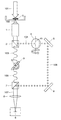
本発明の一実施形態を、図面を参照して説明する。図1に、本実施形態の分光装置の構成を示している。本分光装置は、光101を照射した試料0から発せられる応答光102に含まれる波長スペクトルの分光分析を行うためのものである。
An embodiment of the present invention will be described with reference to the drawings. FIG. 1 shows the configuration of the spectroscopic device of this embodiment. The present spectroscopic device is for performing spectroscopic analysis of the wavelength spectrum included in the
応答光102は、試料0に光101を照射した結果試料0から放たれるラマン散乱光である。特に、本実施形態では、CARSを利用して生体試料0の調査、判別を行うことを趣旨としている。故に、試料0に照射する光101はポンプ光にストークス光を重畳したものであり、応答光102はCARS光である。
The
ポンプ光及びストークス光101はそれぞれ、ピコ秒レーザやフェムト秒レーザといった超短パルスレーザである。ポンプ光には、近赤外光、例えば波長1064nmのレーザを用いる。ストークス光には、様々な波長成分を万遍なく含んだSC光を用いる。SC光の発生には、フォトニック結晶ファイバ(photonic crystal fiber)と呼ばれる非線形光ファイバや、テーパ状ファイバと呼ばれる通常の光ファイバを伸延してコアを極細に変形させたものを使用する。本実施形態では、ポンプ光用のレーザ光源が発振するレーザをビームスプリッタ等により複数に分割し、一方をそのままポンプ光とし、他方をPCFまたはテーパ状ファイバに入射させてSC光を得、それらを重畳した上で試料0に照射する。
Each of the pump light and the Stokes
本実施形態の分光装置は、試料0に臨む対物レンズ1と、対物レンズ1を通過した応答光102を入力光としてこれを入射させる第一の偏光ビームスプリッタ2と、第一の偏光ビームスプリッタ2から出射する入力光102のp偏光成分103を入射させる第一の多層膜フィルタ3と、第一の偏光ビームスプリッタ2から出射する入力光102のs偏光成分104を入射させる第二の多層膜フィルタ4と、第一の多層膜フィルタ3を透過した光105及び第二の多層膜フィルタ4を透過した光106をそれぞれ入射させて両者を重畳した出力光107を得る第二の偏光ビームスプリッタ7と、第二の偏光ビームスプリッタ7から出射する出力光107を入射させる結像レンズ8と、結像レンズ8を通過した出力光107を受光して撮像を行うイメージセンサ9とを具備する。
The spectroscopic device according to the present embodiment includes an
第一の多層膜フィルタ3及び第二の多層膜フィルタ4はそれぞれ、これに入射する光103、104に含まれる一部の波長成分105、106のみを透過させるものである。各フィルタ3、4は、典型的にはバンドパスフィルタとして機能する干渉フィルタである。尤も、多層膜フィルタ3、4として、干渉フィルタ以外のフィルタ、例えばダイクロイックフィルタを採用することを妨げるものではない。一般的な多層膜フィルタ3、4は、透明基板の表面に誘電体光学薄膜を多層に重ねた構造をなし、入射光が多層膜を通過する過程での膜内多重反射による干渉現象により、所定の波長を選択的に透過させ、それ以外の波長を透過させない、そして極めて急峻な分光透過率変化を達成している。
The first multilayer filter 3 and the second multilayer filter 4 respectively transmit only some
多層膜フィルタ3、4の特徴として、これに入射する光103、104の光軸と交わる角度が変化することで、当該フィルタ3、4を透過する光105、106の波長及び透過しない光の波長が変化することが挙げられる。傾向としては、光103、104が入射するフィルタ3、4の境界面の法線と入射光103、104の光軸とがなす角度である入射角が大きくなるほど、当該フィルタ3、4を透過できる光105、106の波長が短くなる。これは、入射角により光学薄膜内での光路長が伸縮して干渉条件が変化し、その帰結として分光透過率特性が変動するからである。
As a feature of the multilayer filters 3 and 4, the wavelengths of the
本実施形態では、入射光103、104の入射角が0°よりも大きく90°よりも小さい中間的な所定角度、例えば45°であるときに、近赤外光に属する所定波長の光105、106を透過させ、それ以外の波長の光を透過させないように設計したバンドパスフィルタ3、4を用いる。近赤外光の定義は波長が約700nmないし約2500nmの光であるが、入射角45°またはその近傍の入射角におけるバンドパスフィルタ3、4の透過光105、106の中心波長は、約900nmないし約1300nmの範囲内の値であることが好ましい。図2に、バンドパスフィルタ3に対するp偏光の入射光103の入射角と、当該バンドパスフィルタ3を透過する光105の中心波長及びバンド幅、並びにp偏光成分の透過率の一例を示している。図示例では、入射角45°またはその近傍の入射角における透過光105の中心波長が、ポンプ光の波長に等しいか略等しい1064nmとなっている。また、透過光105のバンド幅は、数nm以下である。
In the present embodiment, when the incident angles of the
このような多層膜フィルタ3、4を、例えばガルバノスキャナモータ等の回転駆動装置により回転軸31、41を中心に回転させ、当該フィルタ3、4に入射する光103、104の入射角を増減させることにより、当該フィルタ3、4を透過する光105、106の波長を変化させることが可能である。生体試料0に対するCARS分光分析を行う場合、透過光105、106の波長を近赤外光に属する範囲内で、特に約900nmないし約1300nmの範囲内で変化させ得ることが好ましい。一方で、波長が900nmを下回る短波長の透過光105、106は、必ずしも必要とされない。
The multilayer filters 3 and 4 as described above are rotated about the
本実施形態にあって、第一の多層膜フィルタ3の特性と、第二の多層膜フィルタ4の特性とは同等である。ここに言う「同等の特性」とは、双方のフィルタ3、4の特性の間に個体差のような微少な差が存在することを含んでいるのは勿論である。 In the present embodiment, the characteristics of the first multilayer filter 3 and the characteristics of the second multilayer filter 4 are equivalent. It is needless to say that the “equivalent characteristic” mentioned here includes the existence of a minute difference such as an individual difference between the characteristics of the filters 3 and 4.
但し、多層膜フィルタ3、4に入射する光103、104の入射角と、これを透過する光105、106の波長との関係は、入射光103、104の偏光方向による影響を受ける。第二の多層膜フィルタ4として、第一の多層膜フィルタ3と同等の特性を有するフィルタを用いる場合、第一の偏光ビームスプリッタ2により二分された光103、104の偏光方向が相異なることを考慮に入れなければならない。本実施形態では、第二の多層膜フィルタ4の姿勢及び回転軸41を、第一の多層膜フィルタ3の姿勢及び回転軸31に対して相対的に、第二の多層膜フィルタ4に入射し透過する光104、106の光軸回りに、90°回転させている。例えば、入射光103、104の光軸を含む仮想的な平面(図1の紙面)に対して、第一の多層膜フィルタ3の回転軸31が直交しているとき、第二の多層膜フィルタ4の回転軸41は当該平面と平行となっている。これにより、入力光102のp偏光成分103が入射する第一の多層膜フィルタ3及び当該フィルタ3を回転駆動する制御系と、s偏光成分104が入射する第二の多層膜フィルタ4及び当該フィルタ4を回転駆動する制御系とを共通化できる。
However, the relationship between the incident angles of the
第二の多層膜フィルタ4を透過した光106は、複数枚の全反射ミラー5、6により反射されて、第一の多層膜フィルタ3を透過した光105と直交または略直交する。各ミラー5、6は、位置や角度の調節が可能となっている。また、ミラー5、6間に、焦点調整用のレンズやビームエキスパンダ等を介在させることを妨げない。
The light 106 transmitted through the second multilayer filter 4 is reflected by the plurality of total reflection mirrors 5 and 6, and is orthogonal or substantially orthogonal to the light 105 transmitted through the first multilayer filter 3. The positions and angles of the
第二の偏光ビームスプリッタ7は、第一の多層膜フィルタ3を透過した光105の光軸と、第二の多層膜フィルタ4を透過した光106の光軸とが交わる位置に所在する。そして、それらの光105、106の入射を受け、両者を重畳した出力光107を出射する。
The second
出力光107は、結像レンズ8を経てCCDまたはCMOS等のイメージセンサ9に入射する。イメージセンサ9は、その出力光107を受光して撮像する。なお、必要に応じて、試料0に照射する光101の波長成分その他の不要な光を遮断するためのノッチフィルタまたはバンドストップフィルタを、イメージセンサ9の上流に配置してよい。
The
本実施形態の受光装置の特長は、対象の試料0における、ポンプ光及びSC光101の照射を受けて励起した平面領域を一時にイメージングできる点にある。その撮像領域の大きさは、対物レンズ1と結像レンズ8の焦点距離やイメージセンサ9の視野サイズ及び画素分解能等にも依存するが、数十μm四方ないし2mm四方程度の領域の撮像が可能である。撮影画像の限界分解能は、1μm以下を実現できる。
A feature of the light receiving device of the present embodiment is that a planar region of the target sample 0 excited by the irradiation of the pump light and the SC light 101 can be imaged at one time. The size of the imaging area depends on the focal lengths of the
既に述べた通り、出力光107に含まれる波長、即ちCARS光102から抽出される波長は、多層膜フィルタ3、4の入射角によって決定される。多層膜フィルタ3、4の入射角は、人手によらず自動で、かつ高速に変化させることが可能である。多層膜フィルタ3、4の入射角を徐変させる制御を実行しつつ、イメージセンサ9により出力光107を受光し撮像する処理を反復すれば、CARS光102に含まれ得る様々な波長について、平面領域の画像を獲得できる。つまり、平面領域内の各箇所で発生した応答光102の波長スペクトルを短時間で調査することができる。ひいては、平面領域内の各箇所に存在する分子種や分子構造の同定、各箇所に存在する細胞の判別、生命活性のモニタ等を、実用的な所要時間で遂行できる。
As described above, the wavelength included in the
対象の試料0の大きさが一度に撮像可能な平面領域の大きさを超えているならば、試料0を照射光101及び応答光102の光軸に対して相対的に変位させながら撮像を繰り返せばよいことは言うまでもない。
If the size of the target sample 0 exceeds the size of the plane area that can be imaged at one time, repeat the imaging while displacing the sample 0 relative to the optical axes of the
本実施形態では、入射する入力光102をp偏光成分103とs偏光成分104とに分離する第一の偏光ビームスプリッタ2と、入射する光103のうちの一部の波長成分105のみを透過させるものであり、前記第一の偏光ビームスプリッタ2から出射した一方の光103を入射させるとともに、その光103の光軸に対して交わる角度を操作可能な第一の多層膜フィルタ3と、入射する光104のうちの一部の波長成分106のみを透過させるものであり、前記第一の偏光ビームスプリッタ2から出射した他方の光104を入射させるとともに、その光104の光軸に対して交わる角度を操作可能な第二の多層膜フィルタ4と、前記第一の多層膜フィルタ3を透過した光105及び前記第二の多層膜フィルタ4を透過した光106をそれぞれ入射させて両者を重畳した出力光107を得る第二の偏光ビームスプリッタ7とを具備する分光装置を構成した。
In the present embodiment, the first
多層膜フィルタの入射角を変化させることを通じて当該フィルタを透過する波長成分を選好しようとすると、当該フィルタに入射する光の偏光方向によって透過する光の波長が影響を受ける。だが、本実施形態のように、入力光102を一旦p偏光成分103とs偏光成分104とに分離し、それらを別々に多層膜フィルタ3、4に入射させ、その透過光105、106を再度重畳する構造としたことにより、偏光方向の影響を排除した精確な出力光107を抽出することが可能となる。
If the wavelength component transmitted through the filter is to be selected by changing the incident angle of the multilayer filter, the wavelength of the transmitted light is affected by the polarization direction of the light incident on the filter. However, as in the present embodiment, the
本実施形態によれば、回折格子分光器を使用せず、任意の波長成分を含む出力光107を得られ、しかもその波長成分を速やかに変化させることのできる分光装置を実現できる。
According to the present embodiment, it is possible to realize a spectroscopic device that can obtain the
なお、本発明は以上に詳述した実施形態に限られるものではない。特に、本発明の実用上の用途は、CARS分光分析には限定されない。本発明は、CARSではないラマン分光分析にも当然に適用することができる。その場合、応答光である入力光102は励起光101を試料0に照射することで発生するラマン散乱光であり、出力光107はラマン散乱光102に含まれる任意の波長成分である。
The present invention is not limited to the embodiment described in detail above. In particular, the practical application of the present invention is not limited to CARS spectroscopy. The present invention can naturally be applied to Raman spectroscopic analysis other than CARS. In that case, the
さらに、本発明は、ラマン分光以外の用途、例えば赤外分光分析にも適用することが可能である。その場合、応答光である入力光102は赤外光101を試料0に照射した結果試料0に吸収されなかった(試料0を透過または試料0が反射した)光であり、出力光107はその光102に含まれる任意の波長成分である。
Furthermore, the present invention can be applied to applications other than Raman spectroscopy, such as infrared spectroscopy. In that case, the
本発明は、ダイレクトイメージング、即ち平面的に拡張する領域を一度に結像させる光学系を実現できるものであるが、小さなスポット領域を走査する形でイメージングを行う用途に用いることも可能である。 INDUSTRIAL APPLICABILITY The present invention can realize direct imaging, that is, an optical system that forms an image of a region that expands in a plane at one time, but can also be used for the purpose of performing imaging by scanning a small spot region.
その他、各部の具体的構成は、本発明の趣旨を逸脱しない範囲で種々変形が可能である。 In addition, the specific configuration of each part can be variously modified without departing from the spirit of the present invention.
0…試料
2…第一の偏光ビームスプリッタ
3…第一の多層膜フィルタ
4…第二の多層膜フィルタ
7…第二の偏光ビームスプリッタ
9…イメージセンサ
101…試料に照射する光
102…入力光(ラマン散乱光、CARS光)
103…p偏光成分
104…s偏光成分
105…透過光
106…透過光
107…出力光
0 ...
103 ... p-polarized
Claims (6)
前記対物レンズを通過した応答光を入射させこれをp偏光成分とs偏光成分とに分離する第一の偏光ビームスプリッタと、
入射する光のうちの一部の波長成分のみを透過させるものであり、前記第一の偏光ビームスプリッタから出射した一方の光を入射させるとともに、その光の光軸に対して交わる角度を操作可能な第一の多層膜フィルタと、
入射する光のうちの一部の波長成分のみを透過させるものであり、前記第二の偏光ビームスプリッタから出射した他方の光を入射させるとともに、その光の光軸に対して交わる角度を操作可能な第二の多層膜フィルタと、
前記第一の多層膜フィルタを透過した光及び前記第二の多層膜フィルタを透過した光をそれぞれ入射させて両者を重畳した出力光を得る第二の偏光ビームスプリッタと、
前記第二の偏光ビームスプリッタから出射した出力光を入射させる結像レンズと、
前記結像レンズを通過した出力光を受光することにより前記平面領域の画像を一度に獲得するイメージセンサと
を具備する分光分析装置。 An objective lens that faces the sample and irradiates the sample with a response light generated in a two-dimensionally expanded planar region as a result of irradiating the sample with light.
A first polarization beam splitter that receives the response light that has passed through the objective lens and splits it into a p-polarized component and an s-polarized component;
It transmits only a part of the wavelength component of the incident light, and allows one of the light emitted from the first polarization beam splitter to be incident and the angle intersecting with the optical axis of the light can be controlled. A first multilayer filter,
It transmits only part of the wavelength component of the incident light, and allows the other light emitted from the second polarization beam splitter to be incident and the angle at which it intersects the optical axis of the light can be manipulated. Second multilayer filter,
A second polarization beam splitter that obtains output light that is obtained by superimposing both the light transmitted through the first multilayer filter and the light transmitted through the second multilayer filter, respectively .
An image forming lens which makes the output light emitted from the second polarization beam splitter incident,
A spectroscopic analyzer comprising: an image sensor that receives an image of the planar region at a time by receiving output light that has passed through the imaging lens .
前記第二の多層膜フィルタの姿勢及び当該第二の多層膜フィルタの回転軸の向きを、同フィルタを通過する光の光軸回りに、前記第一の多層膜フィルタの姿勢及び当該第一の多層膜フィルタに対して90°変位させる請求項1記載の分光分析装置。 As the second multilayer filter, a filter having the same characteristics as the first multilayer filter is used,
The orientation of the second multilayer filter and the orientation of the rotation axis of the second multilayer filter are set around the optical axis of the light passing through the filter, and the orientation of the first multilayer filter and the first The spectroscopic analyzer according to claim 1, wherein the spectroscopic analyzer is displaced by 90 ° with respect to the multilayer filter.
Priority Applications (1)
| Application Number | Priority Date | Filing Date | Title |
|---|---|---|---|
| JP2018171147A JP6684875B2 (en) | 2018-09-13 | 2018-09-13 | Spectroscopic analyzer |
Applications Claiming Priority (1)
| Application Number | Priority Date | Filing Date | Title |
|---|---|---|---|
| JP2018171147A JP6684875B2 (en) | 2018-09-13 | 2018-09-13 | Spectroscopic analyzer |
Publications (2)
| Publication Number | Publication Date |
|---|---|
| JP2020041960A JP2020041960A (en) | 2020-03-19 |
| JP6684875B2 true JP6684875B2 (en) | 2020-04-22 |
Family
ID=69798104
Family Applications (1)
| Application Number | Title | Priority Date | Filing Date |
|---|---|---|---|
| JP2018171147A Active JP6684875B2 (en) | 2018-09-13 | 2018-09-13 | Spectroscopic analyzer |
Country Status (1)
| Country | Link |
|---|---|
| JP (1) | JP6684875B2 (en) |
Family Cites Families (11)
| Publication number | Priority date | Publication date | Assignee | Title |
|---|---|---|---|---|
| JPH0690085B2 (en) * | 1985-07-22 | 1994-11-14 | 有限会社光伸光学 | Interference filter spectroscope |
| JP3288397B2 (en) * | 1991-04-02 | 2002-06-04 | 株式会社応用光電研究室 | Optical filter element |
| JPH04326026A (en) * | 1991-04-26 | 1992-11-16 | Fuji Photo Film Co Ltd | Spectrophotometer |
| JP3701047B2 (en) * | 1995-06-06 | 2005-09-28 | 住友大阪セメント株式会社 | Non-polarizing filter with isolator |
| JP2850891B2 (en) * | 1996-12-10 | 1999-01-27 | 日本電気株式会社 | Optical filter module and optical amplifying device using the same |
| JP5100461B2 (en) * | 2008-03-14 | 2012-12-19 | 英明 加納 | LIGHT SOURCE DEVICE FOR NONLINEAR SPECTROSCOPY MEASUREMENT SYSTEM |
| JP2010134346A (en) * | 2008-12-08 | 2010-06-17 | Hamamatsu Photonics Kk | Light source device |
| US8289513B2 (en) * | 2009-05-01 | 2012-10-16 | Chemimage Corporation | System and method for component discrimination enhancement based on multispectral addition imaging |
| WO2013188520A2 (en) * | 2012-06-12 | 2013-12-19 | Yale University | Multimode optical fiber spectrometer |
| EP3153906A1 (en) * | 2015-10-07 | 2017-04-12 | Deutsches Krebsforschungszentrum | Fluorescence microscope instrument comprising an actively switched beam path separator |
| US10969405B2 (en) * | 2016-11-29 | 2021-04-06 | Photothermal Spectroscopy Corp. | Method and apparatus for sub-diffraction infrared imaging and spectroscopy and complementary techniques |
-
2018
- 2018-09-13 JP JP2018171147A patent/JP6684875B2/en active Active
Also Published As
| Publication number | Publication date |
|---|---|
| JP2020041960A (en) | 2020-03-19 |
Similar Documents
| Publication | Publication Date | Title |
|---|---|---|
| JP6810167B2 (en) | Systems and methods for 4D hyperspectral imaging | |
| Wang et al. | Rapid adaptive optical recovery of optimal resolution over large volumes | |
| Gao et al. | 3D live fluorescence imaging of cellular dynamics using Bessel beam plane illumination microscopy | |
| JP5996665B2 (en) | CARS microscope | |
| EP2930496B1 (en) | Raman micro-spectrometry system and method for analyzing microscopic objects in a fluidic sample | |
| JP2006023387A (en) | Microscope | |
| JP6075963B2 (en) | Fluorescence observation method and fluorescence observation apparatus | |
| KR101602353B1 (en) | Methods and appratus for high-throughput label-free cell assay | |
| WO2010095263A1 (en) | Laser microscope | |
| US20130057673A1 (en) | Instrument for the realisation of wide-field images at diverse depths of a specimen | |
| DE102016102286A1 (en) | Apparatus and method for multispot scanning microscopy | |
| JP6357245B2 (en) | Optical analyzer and biomolecule analyzer | |
| JP2022061498A (en) | Confocal Raman analyzer and method | |
| JP6482713B2 (en) | Eye analysis device | |
| US11604144B2 (en) | Total internal reflection enabled wide-field Coherent anti-Stokes Raman scattering microscopy | |
| JP2009047435A (en) | Laser microscope | |
| JP6684875B2 (en) | Spectroscopic analyzer | |
| JP5371362B2 (en) | Laser microscope equipment | |
| CN110824684B (en) | High-speed three-dimensional multi-modal imaging system and method | |
| JPWO2016174963A1 (en) | Microscope equipment | |
| US11815462B2 (en) | Broadband Raman excitation spectroscopy with structured excitation profiles | |
| KR101601899B1 (en) | Methods and appratus for high-throughput label-free cell assay | |
| Gupta | Biosensors technologies: acousto-optic tunable filter-based hyperspectral and polarization imagers for fluorescence and spectroscopic imaging | |
| KR101602359B1 (en) | Methods and appratus for high-throughput label-free cell assay | |
| WO2021124999A1 (en) | Observation device having laser irradiating function |
Legal Events
| Date | Code | Title | Description |
|---|---|---|---|
| A621 | Written request for application examination |
Free format text: JAPANESE INTERMEDIATE CODE: A621 Effective date: 20180913 |
|
| A977 | Report on retrieval |
Free format text: JAPANESE INTERMEDIATE CODE: A971007 Effective date: 20190906 |
|
| A131 | Notification of reasons for refusal |
Free format text: JAPANESE INTERMEDIATE CODE: A131 Effective date: 20190910 |
|
| A521 | Request for written amendment filed |
Free format text: JAPANESE INTERMEDIATE CODE: A523 Effective date: 20191018 |
|
| TRDD | Decision of grant or rejection written | ||
| A01 | Written decision to grant a patent or to grant a registration (utility model) |
Free format text: JAPANESE INTERMEDIATE CODE: A01 Effective date: 20200310 |
|
| A61 | First payment of annual fees (during grant procedure) |
Free format text: JAPANESE INTERMEDIATE CODE: A61 Effective date: 20200330 |
|
| R150 | Certificate of patent or registration of utility model |
Ref document number: 6684875 Country of ref document: JP Free format text: JAPANESE INTERMEDIATE CODE: R150 |
|
| R250 | Receipt of annual fees |
Free format text: JAPANESE INTERMEDIATE CODE: R250 |
|
| R250 | Receipt of annual fees |
Free format text: JAPANESE INTERMEDIATE CODE: R250 |