JP6684168B2 - Image processing apparatus and image processing method - Google Patents
Image processing apparatus and image processing method Download PDFInfo
- Publication number
- JP6684168B2 JP6684168B2 JP2016127850A JP2016127850A JP6684168B2 JP 6684168 B2 JP6684168 B2 JP 6684168B2 JP 2016127850 A JP2016127850 A JP 2016127850A JP 2016127850 A JP2016127850 A JP 2016127850A JP 6684168 B2 JP6684168 B2 JP 6684168B2
- Authority
- JP
- Japan
- Prior art keywords
- image
- images
- unit
- depth
- subject
- Prior art date
- Legal status (The legal status is an assumption and is not a legal conclusion. Google has not performed a legal analysis and makes no representation as to the accuracy of the status listed.)
- Expired - Fee Related
Links
- 238000012545 processing Methods 0.000 title claims description 35
- 238000003672 processing method Methods 0.000 title description 6
- 230000015572 biosynthetic process Effects 0.000 claims description 8
- 238000003786 synthesis reaction Methods 0.000 claims description 8
- 238000000034 method Methods 0.000 description 29
- 230000003287 optical effect Effects 0.000 description 21
- 238000010586 diagram Methods 0.000 description 8
- 238000003384 imaging method Methods 0.000 description 7
- 238000001514 detection method Methods 0.000 description 6
- 210000001747 pupil Anatomy 0.000 description 6
- 238000006243 chemical reaction Methods 0.000 description 4
- 230000004907 flux Effects 0.000 description 4
- 230000006870 function Effects 0.000 description 3
- 238000004891 communication Methods 0.000 description 2
- 238000005401 electroluminescence Methods 0.000 description 2
- 230000000295 complement effect Effects 0.000 description 1
- 239000002131 composite material Substances 0.000 description 1
- 238000012937 correction Methods 0.000 description 1
- 239000004973 liquid crystal related substance Substances 0.000 description 1
- 238000004519 manufacturing process Methods 0.000 description 1
- 239000011159 matrix material Substances 0.000 description 1
- 239000000203 mixture Substances 0.000 description 1
- 238000012986 modification Methods 0.000 description 1
- 230000004048 modification Effects 0.000 description 1
- ORQBXQOJMQIAOY-UHFFFAOYSA-N nobelium Chemical compound [No] ORQBXQOJMQIAOY-UHFFFAOYSA-N 0.000 description 1
- 239000004065 semiconductor Substances 0.000 description 1
- 230000002194 synthesizing effect Effects 0.000 description 1
Images


Classifications
-
- G—PHYSICS
- G02—OPTICS
- G02B—OPTICAL ELEMENTS, SYSTEMS OR APPARATUS
- G02B7/00—Mountings, adjusting means, or light-tight connections, for optical elements
- G02B7/28—Systems for automatic generation of focusing signals
- G02B7/36—Systems for automatic generation of focusing signals using image sharpness techniques, e.g. image processing techniques for generating autofocus signals
-
- G—PHYSICS
- G02—OPTICS
- G02B—OPTICAL ELEMENTS, SYSTEMS OR APPARATUS
- G02B27/00—Optical systems or apparatus not provided for by any of the groups G02B1/00 - G02B26/00, G02B30/00
- G02B27/0075—Optical systems or apparatus not provided for by any of the groups G02B1/00 - G02B26/00, G02B30/00 with means for altering, e.g. increasing, the depth of field or depth of focus
-
- H—ELECTRICITY
- H04—ELECTRIC COMMUNICATION TECHNIQUE
- H04N—PICTORIAL COMMUNICATION, e.g. TELEVISION
- H04N21/00—Selective content distribution, e.g. interactive television or video on demand [VOD]
- H04N21/40—Client devices specifically adapted for the reception of or interaction with content, e.g. set-top-box [STB]; Operations thereof
- H04N21/43—Processing of content or additional data, e.g. demultiplexing additional data from a digital video stream; Elementary client operations, e.g. monitoring of home network or synchronising decoder's clock; Client middleware
- H04N21/431—Generation of visual interfaces for content selection or interaction; Content or additional data rendering
- H04N21/4312—Generation of visual interfaces for content selection or interaction; Content or additional data rendering involving specific graphical features, e.g. screen layout, special fonts or colors, blinking icons, highlights or animations
-
- H—ELECTRICITY
- H04—ELECTRIC COMMUNICATION TECHNIQUE
- H04N—PICTORIAL COMMUNICATION, e.g. TELEVISION
- H04N23/00—Cameras or camera modules comprising electronic image sensors; Control thereof
- H04N23/60—Control of cameras or camera modules
- H04N23/62—Control of parameters via user interfaces
-
- H—ELECTRICITY
- H04—ELECTRIC COMMUNICATION TECHNIQUE
- H04N—PICTORIAL COMMUNICATION, e.g. TELEVISION
- H04N23/00—Cameras or camera modules comprising electronic image sensors; Control thereof
- H04N23/60—Control of cameras or camera modules
- H04N23/63—Control of cameras or camera modules by using electronic viewfinders
- H04N23/631—Graphical user interfaces [GUI] specially adapted for controlling image capture or setting capture parameters
- H04N23/632—Graphical user interfaces [GUI] specially adapted for controlling image capture or setting capture parameters for displaying or modifying preview images prior to image capturing, e.g. variety of image resolutions or capturing parameters
-
- H—ELECTRICITY
- H04—ELECTRIC COMMUNICATION TECHNIQUE
- H04N—PICTORIAL COMMUNICATION, e.g. TELEVISION
- H04N23/00—Cameras or camera modules comprising electronic image sensors; Control thereof
- H04N23/70—Circuitry for compensating brightness variation in the scene
- H04N23/743—Bracketing, i.e. taking a series of images with varying exposure conditions
-
- H—ELECTRICITY
- H04—ELECTRIC COMMUNICATION TECHNIQUE
- H04N—PICTORIAL COMMUNICATION, e.g. TELEVISION
- H04N23/00—Cameras or camera modules comprising electronic image sensors; Control thereof
- H04N23/95—Computational photography systems, e.g. light-field imaging systems
- H04N23/951—Computational photography systems, e.g. light-field imaging systems by using two or more images to influence resolution, frame rate or aspect ratio
-
- H—ELECTRICITY
- H04—ELECTRIC COMMUNICATION TECHNIQUE
- H04N—PICTORIAL COMMUNICATION, e.g. TELEVISION
- H04N23/00—Cameras or camera modules comprising electronic image sensors; Control thereof
- H04N23/95—Computational photography systems, e.g. light-field imaging systems
- H04N23/958—Computational photography systems, e.g. light-field imaging systems for extended depth of field imaging
- H04N23/959—Computational photography systems, e.g. light-field imaging systems for extended depth of field imaging by adjusting depth of field during image capture, e.g. maximising or setting range based on scene characteristics
-
- H—ELECTRICITY
- H04—ELECTRIC COMMUNICATION TECHNIQUE
- H04N—PICTORIAL COMMUNICATION, e.g. TELEVISION
- H04N21/00—Selective content distribution, e.g. interactive television or video on demand [VOD]
- H04N21/40—Client devices specifically adapted for the reception of or interaction with content, e.g. set-top-box [STB]; Operations thereof
- H04N21/41—Structure of client; Structure of client peripherals
- H04N21/422—Input-only peripherals, i.e. input devices connected to specially adapted client devices, e.g. global positioning system [GPS]
- H04N21/4223—Cameras
-
- H—ELECTRICITY
- H04—ELECTRIC COMMUNICATION TECHNIQUE
- H04N—PICTORIAL COMMUNICATION, e.g. TELEVISION
- H04N21/00—Selective content distribution, e.g. interactive television or video on demand [VOD]
- H04N21/40—Client devices specifically adapted for the reception of or interaction with content, e.g. set-top-box [STB]; Operations thereof
- H04N21/43—Processing of content or additional data, e.g. demultiplexing additional data from a digital video stream; Elementary client operations, e.g. monitoring of home network or synchronising decoder's clock; Client middleware
- H04N21/433—Content storage operation, e.g. storage operation in response to a pause request, caching operations
- H04N21/4334—Recording operations
-
- H—ELECTRICITY
- H04—ELECTRIC COMMUNICATION TECHNIQUE
- H04N—PICTORIAL COMMUNICATION, e.g. TELEVISION
- H04N21/00—Selective content distribution, e.g. interactive television or video on demand [VOD]
- H04N21/40—Client devices specifically adapted for the reception of or interaction with content, e.g. set-top-box [STB]; Operations thereof
- H04N21/47—End-user applications
- H04N21/482—End-user interface for program selection
Landscapes
- Engineering & Computer Science (AREA)
- Multimedia (AREA)
- Signal Processing (AREA)
- Physics & Mathematics (AREA)
- General Physics & Mathematics (AREA)
- Optics & Photonics (AREA)
- Human Computer Interaction (AREA)
- Computing Systems (AREA)
- Theoretical Computer Science (AREA)
- Computer Vision & Pattern Recognition (AREA)
- Studio Devices (AREA)
- Focusing (AREA)
- Indication In Cameras, And Counting Of Exposures (AREA)
- Automatic Focus Adjustment (AREA)
Description
本発明は、画像処理装置および画像処理方法に関し、特に、ユーザが所望する領域にピントが合った画像を得ることができる画像処理装置および画像処理方法に関する。 The present invention relates to an image processing apparatus and an image processing method, and more particularly to an image processing apparatus and an image processing method capable of obtaining an image in which a region desired by a user is in focus.
従来、ピント位置を変化させながら連続して撮影を行うフォーカスブラケット撮影が知られている。フォーカスブラケット撮影を行うことにより、被写体に対し異なる領域にピントが合った複数の画像を取得することができる。 2. Description of the Related Art Conventionally, focus bracket shooting is known in which shooting is continuously performed while changing a focus position. By performing focus bracket photography, it is possible to acquire a plurality of images in which different regions of the subject are in focus.
特許文献1では、フォーカスブラケット撮影を行う撮像装置が開示されている。特許文献1の撮像装置は、フォーカスブラケット撮影で得られた複数の画像の中から、ユーザにより指示された領域に対し最もピントの合った画像を選択する。
しかしながら、特許文献1に開示された技術では、ユーザが所望する画像を必ずしも取得できないという問題がある。例えば、被写界深度が異なる複数の画像が取得された場合、ユーザの指示領域に対しピントの合った画像が複数該当することがある。このような場合、該当した画像のうちのいずれの被写界深度の画像をユーザが望んでいるかを判断することは困難である。
However, the technique disclosed in
本発明は上述の問題に鑑み、ユーザの好みに合った被写界深度を有する画像を得ることが可能な画像処理装置および画像制御方法を提供することを目的とする。 In view of the above problems, it is an object of the present invention to provide an image processing apparatus and an image control method capable of obtaining an image having a depth of field that suits a user's preference.
本発明に係る画像処理装置は、被写体に対し、被写界深度が異なる複数の画像を取得する画像取得部と、前記被写体の任意の領域をユーザが指示するための指示部と、前記被写界深度および前記領域の被写体距離に基づき、前記複数の画像の中から少なくとも2つの候補画像を選択する第1選択部と、前記候補画像を表示器に表示するよう制御する表示制御部と、前記候補画像の中から前記ユーザが画像を選択するための第2選択部とを備えることを特徴とする。 An image processing apparatus according to the present invention includes an image acquisition unit that acquires a plurality of images having different depths of field for a subject, an instruction unit for a user to instruct an arbitrary region of the subject, and the subject A first selection unit that selects at least two candidate images from the plurality of images based on a depth of field and a subject distance in the region; a display control unit that controls the display of the candidate images ; A second selection unit for the user to select an image from the candidate images is provided.
本発明に係る画像処理方法は、被写体に対し、被写界深度が異なる複数の画像を取得するステップと、前記被写体の任意の領域をユーザが指示するための画像を決定するステップと、前記被写界深度および前記領域の被写体距離に基づき、前記複数の画像の中から少なくとも2つの候補画像を選択するステップと、前記候補画像を表示器に表示するよう制御するステップと、前記候補画像の中から前記ユーザが選択した画像を決定するステップとを備えることを特徴とする。 An image processing method according to the present invention includes a step of acquiring a plurality of images having different depths of field for a subject, a step of determining an image for a user to designate an arbitrary region of the subject, Selecting at least two candidate images from the plurality of images based on the depth of field and the subject distance in the region; controlling the candidate images to be displayed on a display; And determining the image selected by the user.
本発明によれば、ユーザの好みに合った被写界深度を有する画像を取得することができる。 According to the present invention, it is possible to acquire an image having a depth of field that matches a user's preference.
以下、図面を参照しながら本発明の好適な実施の形態について説明する。 Hereinafter, preferred embodiments of the present invention will be described with reference to the drawings.
[第1実施形態]
第1実施形態の画像処理装置は、被写界深度が異なる複数の画像の中から、ユーザが指示した位置に対してピントが合った画像を提示し、記録することができる。以下の説明において、本実施形態の画像処理における撮影モードを、ピント位置指定モードと称する。
[First Embodiment]
The image processing apparatus according to the first embodiment can present and record an image in focus at a position designated by the user from among a plurality of images having different depths of field. In the following description, the shooting mode in the image processing of this embodiment will be referred to as the focus position designation mode.
図1は、本実施形態に係る画像処理装置のブロック図である。画像処理装置は、光学系101、撮像素子102、信号処理部103、内部メモリ104、光学系制御部105、制御部106、操作部107、表示部108、記録部109を備えている。
FIG. 1 is a block diagram of an image processing apparatus according to this embodiment. The image processing apparatus includes an
光学系101は、ズームレンズ101a、フォーカスレンズ101b、絞りシャッタ101cを備えている。光学系101は、被写体からの光を撮像素子102の撮像面に結像させ、被写体像を形成する。ズームレンズ101a、フォーカスレンズ101b、絞りシャッタ101cは、光学系制御部105により制御され、撮像素子102に到達する被写体像の倍率、ピント位置、光量をそれぞれ調整する。
The
撮像素子102は、CCD(Charge Coupled Device)、CMOS(Complementary MOS)センサなどの光電変換素子である。撮像素子102は、光学系101を通過した被写体の光束を光電変換し、アナログ画像信号として信号処理部103に入力する。
The
信号処理部103は、入力されたアナログ画像信号をデジタル画像信号に変換するアナログ・デジタル変換回路を備えている。さらに、信号処理部103は、デジタル画像信号に対し、ホワイトバランス調整、補間、輪郭強調、ガンマ補正、階調変換などの所定の画像処理を施す。なお、アナログ・デジタル変換回路は撮像素子102に設けられてもよい。
The
内部メモリ104は、DRAM(Dynamic Random Access Memory)などから構成され、信号処理部103からの画像を一時的に記憶する。また、内部メモリ104は、制御プログラムが読み出されるロード領域、各種処理を行う際のワーク領域として、制御部106により使用される。
The
光学系制御部105は、ズーム駆動部105a、フォーカス駆動部105b、絞りシャッタ駆動部105cを備えている。光学系制御部105は、制御部106からの撮影条件に基づいて、ズーム駆動部105a、フォーカス駆動部105b、絞りシャッタ駆動部105cの駆動量、駆動タイミングなどを制御する。ズーム駆動部105a、フォーカス駆動部105bは、ズームレンズ101a、フォーカスレンズ101bをそれぞれ光軸に沿って移動させる。絞りシャッタ駆動部105cは、絞りシャッタ101cの開口径を変化させる。
The optical
制御部106は、CPU(Central Processing Unit)などから構成され、操作部107からの指示に基づいて、撮像素子102、信号処理部103、光学系制御部105などの画像処理装置の各部に制御信号を送信する。制御部106は、被写体検出部111、距離取得部112、条件設定部113、深度合成部114、画像提示部115の機能を備えており、画像取得部、指示部、提示部、選択部を構成する。
The
被写体検出部111は、取得した画像の被写体領域を検出する。距離取得部112は、被写体領域の距離情報、例えば被写体距離を取得する。条件設定部113は、距離情報に基づき被写体を撮影する際の撮影条件を設定する。深度合成部114は、深度合成処理を行う。深度合成処理とは、被写界深度の浅い複数の画像を合成することにより、被写界深度の深い1つの画像を生成する処理である。画像提示部115は、操作部107または表示部108からの入力信号に基づき、ユーザが指示した被写体領域を特定する。画像提示部115は、特定した被写体領域の距離情報に基づき、被写界深度が異なる複数の画像の中から画像を選択し、ユーザに提示する。
The
操作部107は、撮影ボタン107a、モード切替ボタン107b、カーソルキー107cなどの各種操作デバイスを備えている。操作部107は、ユーザが画像処理装置に対し指示を行うためのものであり、ユーザの操作に応じた信号を制御部106に入力する。ユーザは、例えばカーソルキー107cを操作することにより、表示部108に表示された画像の任意の領域を指示することができる。なお、表示部108のタッチセンサ108aも操作部107に含まれ得る。モード切替ボタン107bは、撮影条件に関する撮影モードの切り替えの他、撮影された画像の選択に関する画像選択モードの切り替えの機能を有する。本実施形態においては、画像選択モードには、被写界深度および指定したピント位置に基づき候補画像を提示させることにより、所望の画像を選択するためのモード(ピント位置指定モード)が含まれ得る。
The
表示部108は、タッチセンサ108a、ディスプレイ108bなどから構成されている。タッチセンサ108aは、ディスプレイ108b上に設けられ、マトリクス状に並べられた透明な電極を備えている。ユーザのタッチ操作、すなわちユーザの指がタッチセンサ108aに触れることにより、電極における静電容量が変化する。これにより、タッチセンサ108aは、指の接触位置およびその軌跡を検出することができる。タッチセンサ108aは、このようなタッチ操作に応じた信号を制御部106に入力する。ディスプレイ108bは、例えば液晶ディスプレイ、有機EL(Electro Luminescence)ディスプレイで構成され、信号処理部103で生成された画像、内部メモリ104、記録部109から読み出した画像、各種設定情報などを表示する。
The
記録部109は、半導体メモリ、光磁気ディスクなどの情報記録媒体であり、制御部106から出力された画像などを記録する。記録部109は、着脱可能に構成されてもよく、また、外部の装置で生成された画像を記録してもよい。さらに、画像処理装置は、ネットワークに接続する通信部を備えてもよく、通信部を介してネットワーク上のサーバと画像を送受信することも可能である。
The
図2は、本実施形態に係る撮像素子102の模式図である。図2は、光学系101と撮像素子102を光軸に対して垂直な方向から示している。図示の便宜上、光学系101の射出瞳101dと撮像素子102の1つの画素のみが示されている。撮像素子102の各画素は、等分割された副画素201、202を有している。副画素201、202は、それぞれ1つのフォトダイオードで構成される。撮像素子102の各画素には、受光面側にマイクロレンズ203が形成されている。射出瞳101dの異なる瞳領域211、212を通過した被写体からの光は、マイクロレンズ203を介して、対応する副画素201、202にそれぞれ入射する。
FIG. 2 is a schematic diagram of the
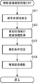
図3は、本実施形態に係る画像処理方法の概要を表すフローチャートである。まず、ユーザがモード切替ボタン107bを操作し、ピント位置指定モードを選択する。続いて、ユーザが撮影ボタン107aを押下すると、ステップS301において、制御部106は、ピント位置を変えながら複数の画像を撮影する。すなわち、制御部106は、被写体として検出した被写体領域の距離情報を取得し、該距離情報に基づいて、ピント位置を変化させながらブラケット撮影を行う。撮影された複数の画像は、内部メモリ104に一時的に保持される。
FIG. 3 is a flowchart showing an outline of the image processing method according to this embodiment. First, the user operates the
ステップS302において、制御部106は、撮影された複数の画像を深度合成し、被写界深度の深い画像を生成する。制御部106は、ピント位置の異なる複数の画像を合成し、被写界深度の深い画像を生成する。生成された画像は内部メモリ104に一時的に保持される。
In step S302, the
ステップS303において、制御部106は、候補画像を表示する。制御部106は、これまでの処理で得られた画像の中から、ユーザの意図に近いと推定された少なくとも2つの候補画像を選択し、表示部108に表示する。例えば、ユーザが表示部108において画像の任意の領域を指定すると、制御部106は、被写界深度および指示された領域の被写体距離に基づき、撮像された複数の画像から少なくとも2つの画像を表示する。ユーザは、表示部108に表示された画像の中から、所望の1つの画像を選択する。
In step S303, the
ステップS304において、制御部106は、ユーザによって選択された画像を決定し、記録部109に記録する。制御部106は、選択された画像以外の画像を内部メモリ104から消去する。
In step S304, the
図4は、図3の画像撮影処理(S301)の詳細なフローチャートである。まず、ステップS401において、制御部106の被写体検出部111は、取得した画像において被写体領域の検出を行う。被写体領域の一例を図5(a)に示す。被写体検出部111は、画像501を複数のブロック501aに分割し、各ブロックの輝度および色情報を取得する。次に、被写体検出部111は、画像501の中央部に属するブロックの情報と類似する情報を有するブロックの集合を、被写体領域502として検出する。なお、被写体領域の検出方法は限定されるものではなく、例えば、画像から輝度、色、コントラスト分布などに関する特徴量を抽出し、事前にモデル化した特徴量と比較することにより、被写体領域を検出する方法でもよい。
FIG. 4 is a detailed flowchart of the image capturing process (S301) of FIG. First, in step S401, the
次に、ステップS402において、制御部106の距離取得部112は、被写体領域502の距離情報を取得する。距離情報には、撮影時における光学系101から被写体までの距離、すなわち被写体距離が含まれる。図6、図5(b)を用いて、ステップS402の処理を詳述する。
Next, in step S402, the
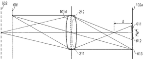
図6は、本実施形態に係る距離情報の取得方法を説明するための図である。図6は、被写体が位置601、602に存在する場合において、光学系101の射出瞳101dと、撮像素子102の撮像面102aとの間の光学的な位置関係を示している。位置601にある被写体はピントが合った状態であり、異なる瞳領域211、212を通過した被写体からの光束は、撮像面102a上の同じ位置613で結像する。一方、位置602にある被写体はピントが合っていない状態である。この場合、異なる瞳領域211、212を通過した光束はそれぞれ、撮像面102a上で幅611、612の範囲に広がり、ボケた被写体像となる。距離取得部112は、これらの被写体像のずれ量pをデフォーカス量dに変換し、光学系101のレンズ情報に基づいて被写体距離を算出する。なお、被写体距離の取得方法は限定されるものではなく、例えば赤外線などを利用した測距センサにより被写体距離を測定する方法でもよい。
FIG. 6 is a diagram for explaining the distance information acquisition method according to the present embodiment. FIG. 6 shows an optical positional relationship between the
図5(b)は、本実施形態に係る被写体領域502の距離分布の一例である。グラフの横軸は各画素の被写体距離を示し、縦軸は画素数を示している。距離取得部112は、被写体領域502に対して、図5(b)に示す距離分布を作成する。距離取得部112は、度数のピークが含まれる分布504を被写体503の距離情報と判断し、最小の距離Zminおよび最大の距離Zmaxを取得する。ピークから離れた位置にある分布505は、被写体領域502に混入した背景領域の距離情報を示すものであり、除外される。
FIG. 5B is an example of the distance distribution of the
次に、ステップS403、S404において、制御部106の条件設定部113は、撮影条件を設定し、複数の画像を撮影する。撮影条件には、フォーカスレンズ101bの位置、絞りシャッタ101cの絞り値などが含まれる。図7を用いて、ステップS403、ステップS404の処理を詳述する。
Next, in steps S403 and S404, the
図7は、本実施形態に係る撮影方法を説明するための図である。ステップS402において取得されたように、被写体503の被写体距離は、距離Zminから距離Zmaxまでの範囲にある。まず、条件設定部113は、フォーカスブラケット撮影を行うための撮影条件を設定する。例えば、条件設定部113は、被写体503を距離の順で4つの領域に分割し、各領域が1回の撮影で被写界深度内に収まるように、絞りシャッタ101cの絞り値を設定する。そして、条件設定部113は、被写界深度に応じて、ブラケット幅、すなわちフォーカスレンズ101bの撮影毎の位置を設定する。
FIG. 7 is a diagram for explaining the shooting method according to the present embodiment. As acquired in step S402, the subject distance of the subject 503 is in the range from the distance Zmin to the distance Zmax. First, the
さらに、条件設定部113は、被写界深度の深い画像を撮影するための撮影条件を設定する。例えば、条件設定部113は、被写体503の全体が1回の撮影で被写界深度内に収まるように、絞りシャッタ101cの絞り値、フォーカスレンズ101bの位置を設定する。すなわち、条件設定部113は、フォーカスブラケット撮影の撮影条件よりも絞り値を大きく設定する。
Furthermore, the
続いて、制御部106は、撮影条件を光学系制御部105に送信する。光学系制御部105は、撮影条件に基づいてフォーカス駆動部105bを駆動し、フォーカスレンズ101bの位置を光軸に沿って4段階ブラケットさせる。制御部106は、撮像素子102、信号処理部103を制御し、各ブラケット位置において順次撮影を行う。これにより、距離Zmin〜距離Z1までの被写界深度を有する画像1から、距離Z3〜距離Zmaxまでの被写界深度を有する画像4までの4つの画像が取得される。
Then, the
さらに、光学系制御部105は、撮影条件に基づいてフォーカス駆動部105b、絞りシャッタ駆動部105cを駆動し、フォーカスレンズ101bの位置、絞りシャッタ101cの絞り値を調節する。制御部106は、撮像素子102、信号処理部103を制御し、画像を1つ撮影する。これにより、距離Zmin〜距離Zmaxまでの被写界深度を有する画像5が取得される。
Further, the optical
図8は、図3の深度合成処理(S302)の詳細なフローチャートである。深度合成処理では、複数の画像撮影により取得された画像1〜4が合成され、画像6が生成される。まず、ステップS801において、制御部106の深度合成部114は、処理対象となる画素を1つ選択する。画素の選択順は、例えば画像の端から順に行えばよく、特に限定されない。
FIG. 8 is a detailed flowchart of the depth stacking process (S302) of FIG. In the depth stacking process,
ステップS802において、深度合成部114は、画像1〜4の中から、画像を1つ選択する。画像の選択順は、例えば画像1から番号順に行えばよく、特に限定されない。ステップS803において、深度合成部114は、選択した画像における対象画素の被写体距離を距離取得部112から取得する。
In step S802, the
ステップS804において、深度合成部114は、被写体距離に応じて対象画素の合成比率を決定する。図9に示されるように、深度合成部114は、被写界深度内に含まれる画素に対して合成比率を高く設定する。例えば、画像2が選択されている場合、画像2の被写界深度内(Z1〜Z2)に含まれる画素の合成比率が高く設定される。
In step S804, the
ステップS805において、深度合成部114は、元の画素値に合成比率を乗算することにより、合成画素値を算出する。ステップS806において、深度合成部114は、全画像(画像1〜4)に対して合成画素値の算出が完了したか否かを判定する。合成画素値が算出されていない画像がある場合、深度合成部114は、ステップS802に戻り、次の画像を選択する。
In step S805, the
ステップS807において、深度合成部114は、画像1〜4の合成画素値を合算し、画像6の画素値とする。ステップS808において、深度合成部114は、全画素に対して画像6の画素値が得られたか否かを判定する。画素値が得られていない画素がある場合、深度合成部114は、ステップS801に戻り、次の画素を選択する。
In step S807, the
ステップS809において、深度合成部114は、画像6を内部メモリ104に記憶させる。さらに、深度合成部114は、これまでの処理で得られた画像1から画像6までの6つの画像の深度情報を内部メモリ104に記憶させる。深度合成部114は、各画像とその深度情報とを記録部109に記憶させてもよい。
In step S809, the
図10は、本実施形態に係る画像の深度情報の表である。深度情報には、各画像の被写界深度内の被写体距離の最大値および最小値が含まれる。本実施形態では、画像5と画像6は、同等の被写界深度を有している。画像5は絞りを絞って撮影されているため、画像5の手振れ量とSN比は画像6よりも悪化しており、画像5の背景ボケの程度は小さい。一方、画像6の画質は、合成処理により劣化している可能性がある。
FIG. 10 is a table of image depth information according to the present embodiment. The depth information includes the maximum value and the minimum value of the subject distance within the depth of field of each image. In this embodiment, the
図11は、図3の候補画像表示処理(S303)のフローチャートである。まず、ステップS1101において、制御部106の画像提示部115は、図12(a)に示すような指示受付用の画像を表示部108に表示させる。ピント位置指定モードでは、ピントを合わせたい位置をユーザにタッチしてもらうため、指示受付用の画像は画像全体にわたって視認性が高い画像であることが好ましい。よって、画像提示部115は、被写界深度の深い画像5または画像6を指示受付用の画像とする。
FIG. 11 is a flowchart of the candidate image display process (S303) of FIG. First, in step S1101, the
ステップS1102において、画像提示部115は、ユーザからの指示を受け付ける。例えば、画像提示部115は、図12(a)に示すように、自動車1200のフロント部分がユーザによりタッチされた場合、タッチセンサ108aからタッチ箇所1201の座標を受け取る。
In step S1102, the
ステップS1103において、画像提示部115は、タッチ箇所1201の距離情報を取得する。具体的には、画像提示部115は、タッチ箇所1201の画素の被写体距離を距離取得部112から取得する。また、タッチ箇所1201が複数画素にまたがる場合、画像提示部115は、複数画素の被写体距離の平均値をとる。
In step S1103, the
ステップS1104において、画像提示部115は、距離情報に基づき、候補画像の選択を行う。タッチ箇所1201の被写体距離をZtで表すと、図12(b)の例では、距離Ztは、距離Zminと距離Z1の間にある(Zmin≦Zt≦Z1)。したがって、画像提示部115は、画像1〜6の中から、距離Ztを被写界深度内に含む画像をすべて選択する。すなわち、画像提示部115は、図12の例では、画像1、画像5、画像6を候補画像として選択する。なお、距離Ztが距離Zmin未満、または距離Zmaxよりも大きい場合、画像提示部115は、ユーザに対する警告表示を表示部108に表示させてもよい。また、警告表示の代わりに、あるいは警告表示に加えて、画像提示部115は、画像1〜6の中で相対的に最も背景ボケの少ない画像5を選択してもよい。
In step S1104, the
ステップS1105において、画像提示部115は、選択した候補画像を表示部108に表示させる。画像提示部115は、候補画像として画像1、画像5、画像6を選択した場合、図13に示すように、選択した3つの画像を表示部108に並べて表示させる。また、画像提示部115は、候補画像とともに、好みの画像を選択することをユーザに促す表示を表示部108に表示する。
In step S1105, the
このように、本実施形態によれば、ピント位置が異なる複数の画像とこれらの画像を深度合成することで得られた画像とを、それぞれの被写界深度とともに記憶する。そして、ユーザが指示した領域の被写体距離と各画像の被写界深度を基に、被写界深度の異なる少なくとも2つの画像をユーザに提示する。これにより、ユーザが所望の画像を選択することができるため、ユーザの好みを反映した被写界深度を有する画像を記録することができる。 As described above, according to the present embodiment, a plurality of images having different focus positions and an image obtained by subjecting these images to depth synthesis are stored together with their respective depths of field. Then, based on the subject distance of the area designated by the user and the depth of field of each image, at least two images having different depths of field are presented to the user. This allows the user to select a desired image, so that an image having a depth of field that reflects the user's preference can be recorded.
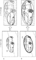
図14(a)は、本実施形態に係る指示受付用の画像の一例である。ユーザのタッチ操作により自動車のフロント部分1401が指示されたと仮定する。その場合、図14(b)に示すように、自動車のフロント部分の近傍1402のみにピントが合った画像Aが所望であると考えられる一方で、図14(c)に示すように、自動車全体1403にピントが合った画像Bが所望であるとも考えられる。一般に、画像A、Bのうちどちらの画像をユーザが望んでいるかを判断することは困難であるが、本実施形態によれば、最終的な判断をユーザに委ねることにより、真にユーザの意図を反映した画像を取得することができる。
FIG. 14A is an example of an image for instruction reception according to the present embodiment. It is assumed that the
[第2実施形態]
第1実施形態では、ユーザが指示受付用の画像上の1点を指示することを想定していたが、本実施形態では、ユーザの指示が必ずしも1点のみではない場合を想定する。以下、第1実施形態と異なる点を中心に説明を行う。
[Second Embodiment]
In the first embodiment, it is assumed that the user specifies one point on the image for accepting the instruction, but in the present embodiment, it is assumed that the user does not always specify only one point. Hereinafter, description will be made focusing on the points different from the first embodiment.
図15は、本実施形態に係る候補画像表示処理のフローチャートである。まず、ステップS1501において、画像提示部115は、図16に示すような指示受付用の画像を表示部108に表示させる。
FIG. 15 is a flowchart of the candidate image display process according to this embodiment. First, in step S1501, the
ステップS1502において、画像提示部115は、ユーザからの指示を受け付ける。画像提示部115は、図16(a)に示すように、自動車のフロント部分がユーザによりタッチされた場合、タッチセンサ108aからタッチ箇所1601の座標を受け取る。また、画像提示部115は、図16(b)に示すように、被写体である自動車全体を囲むようにユーザがタッチ操作を行った場合、タッチセンサ108aからタッチ箇所のすべての座標、すなわちタッチ箇所の軌跡1602を受け取る。
In step S1502, the
ステップS1503およびS1504において、画像提示部115は、候補画像を選択し、候補画像の優先度を設定する。画像提示部115は、ユーザのタッチ操作の種類に基づき、優先度を設定する。例えば、図16(a)に示すように、被写体上の1点が指示された場合(ピンポイント指定時)、画像提示部115は、指示された位置の近傍のみピントが合った画像がユーザの所望である可能性が高いと判断する。一方、図16(b)に示すように、被写体全体を囲むように指示された場合(囲み指定時)、画像提示部115は、被写体全体にピントが合った画像がユーザの所望である可能性が高いと判断する。
In steps S1503 and S1504, the
画像提示部115は、このような可能性の高低を、候補画像の提示の優先度として反映する。例えば、図12(b)、図16(a)のように、被写体のある1点のみを指示された場合、画像提示部115は、画像1、画像5、画像6を候補画像として選択し、画像1の提示の優先度を最も高く設定する。逆に、図16(b)のように、被写体全体を囲むように指定された場合、画像提示部115は、画像5、画像6の提示の優先度を高く設定する。すなわち、候補画像の提示の優先度は、ユーザの指示の仕方に応じて設定される。
The
ステップS1505において、画像提示部115は、表示部108に候補画像を表示させる。画像提示部115は、提示の優先度に従って候補画像の表示を行う。
In step S1505, the
図17は、本実施形態に係る候補画像の表示の一例を示す図である。図17(a)は、ピンポイント指定時に、被写界深度の浅い画像1が高優先度に設定された場合の表示例である。一方、図17(b)は、囲み指定時に、被写界深度の深い画像5、画像6が高優先度に設定された場合の表示例である。図17に示すように、画像提示部115は、提示の優先度が高い画像を最も大きく表示させる。
FIG. 17 is a diagram showing an example of display of candidate images according to the present embodiment. FIG. 17A is a display example when the
このように、本実施形態によれば、ユーザによるタッチ操作の種類により、ユーザの好みを推定し、候補画像に提示の優先度を設けることができる。提示の優先度を表示方法に反映させることで、ユーザが好みに合った画像をより容易に選択することができる。 As described above, according to the present embodiment, it is possible to estimate the user's preference based on the type of touch operation performed by the user and provide the candidate images with the presentation priority. By reflecting the presentation priority in the display method, the user can more easily select an image that suits his or her preference.
[変形実施形態]
本発明は、上述の実施形態に限らず種々の変形が可能である。例えば、上述の実施形態では、フォーカスブラケット撮影により得られた4つの画像(画像1〜4)を深度合成することにより、1つの合成画像(画像6)を生成していた。合成方法は、これに限定されることはなく、任意の個数および組み合わせの画像を深度合成することにより、被写界深度が異なる複数の合成画像を得てもよいものとする。
[Modified Embodiment]
The present invention is not limited to the above-described embodiment, and various modifications can be made. For example, in the above-described embodiment, the four images (
また、ユーザからの指示は、タッチ操作による場合に限定されることはなく、例えばカーソルで指示するなど、その他の種々の手法を用いてもよいものとする。 Further, the instruction from the user is not limited to the case of touch operation, and various other methods such as instructing with a cursor may be used.
また、第2実施形態では、画像の優先度を表示に反映する方法として、画像の大きさに差をつける方式を説明したが、例えば表示順に反映させるなど、その他の種々の手法を用いてもよいものとする。 Further, in the second embodiment, as a method of reflecting the priority of the image on the display, a method of making a difference in the size of the image has been described, but various other methods such as reflecting in the display order may be used. Let's be good.
106 制御部
107 操作部
108 表示部
109 記録部
111 被写体検出部
112 距離取得部
113 条件設定部
114 深度合成部
115 画像提示部
106
Claims (10)
前記被写体の任意の領域をユーザが指示するための指示部と、
前記被写界深度および前記領域の被写体距離に基づき、前記複数の画像の中から少なくとも2つの候補画像を選択する第1選択部と、
前記候補画像を表示器に表示するよう制御する表示制御部と、
前記候補画像の中から前記ユーザが画像を選択するための第2選択部とを備えることを特徴とする画像処理装置。 An image acquisition unit that acquires a plurality of images with different depths of field for the subject,
An instruction unit for a user to instruct an arbitrary area of the subject,
A first selection unit that selects at least two candidate images from the plurality of images based on the depth of field and the subject distance of the region ;
A display control unit that controls to display the candidate image on a display ,
An image processing apparatus comprising: a second selection unit for the user to select an image from the candidate images.
前記被写体の任意の領域をユーザが指示するための画像を決定するステップと、
前記被写界深度および前記領域の被写体距離に基づき、前記複数の画像の中から少なくとも2つの候補画像を選択するステップと、
前記候補画像を表示器に表示するよう制御するステップと、
前記候補画像の中から前記ユーザが選択した画像を決定するステップとを備えることを特徴とする画像処理方法。 Acquiring a plurality of images with different depths of field for the subject,
Determining an image for a user to indicate an arbitrary area of the subject,
Selecting at least two candidate images from the plurality of images based on the depth of field and the subject distance of the region;
Controlling to display the candidate image on a display,
Determining the image selected by the user from the candidate images.
Priority Applications (2)
| Application Number | Priority Date | Filing Date | Title |
|---|---|---|---|
| JP2016127850A JP6684168B2 (en) | 2016-06-28 | 2016-06-28 | Image processing apparatus and image processing method |
| US15/628,147 US10156695B2 (en) | 2016-06-28 | 2017-06-20 | Image processing apparatus and image processing method |
Applications Claiming Priority (1)
| Application Number | Priority Date | Filing Date | Title |
|---|---|---|---|
| JP2016127850A JP6684168B2 (en) | 2016-06-28 | 2016-06-28 | Image processing apparatus and image processing method |
Publications (3)
| Publication Number | Publication Date |
|---|---|
| JP2018006867A JP2018006867A (en) | 2018-01-11 |
| JP2018006867A5 JP2018006867A5 (en) | 2019-08-08 |
| JP6684168B2 true JP6684168B2 (en) | 2020-04-22 |
Family
ID=60676852
Family Applications (1)
| Application Number | Title | Priority Date | Filing Date |
|---|---|---|---|
| JP2016127850A Expired - Fee Related JP6684168B2 (en) | 2016-06-28 | 2016-06-28 | Image processing apparatus and image processing method |
Country Status (2)
| Country | Link |
|---|---|
| US (1) | US10156695B2 (en) |
| JP (1) | JP6684168B2 (en) |
Families Citing this family (3)
| Publication number | Priority date | Publication date | Assignee | Title |
|---|---|---|---|---|
| JP7195790B2 (en) | 2018-07-02 | 2022-12-26 | キヤノン株式会社 | Imaging device and its control method |
| CN108989671A (en) * | 2018-07-25 | 2018-12-11 | Oppo广东移动通信有限公司 | Image processing method, device and electronic equipment |
| US11120528B1 (en) | 2018-09-11 | 2021-09-14 | Apple Inc. | Artificial aperture adjustment for synthetic depth of field rendering |
Family Cites Families (19)
| Publication number | Priority date | Publication date | Assignee | Title |
|---|---|---|---|---|
| US5321525A (en) * | 1992-12-14 | 1994-06-14 | Xerox Corporation | Clustered halftoning with dot-to-dot error diffusion |
| JPH0822091A (en) * | 1994-07-05 | 1996-01-23 | Canon Inc | Stereoscopic image recording method and its device and stereoscopic image forming body |
| US6314198B1 (en) * | 1996-09-25 | 2001-11-06 | Canon Kabushiki Kaisha | Radiographic, digital image processing system |
| US6654060B1 (en) * | 1997-01-07 | 2003-11-25 | Canon Kabushiki Kaisha | Video-image control apparatus and method and storage medium |
| JP3761740B2 (en) * | 1999-04-05 | 2006-03-29 | 株式会社リコー | camera |
| JP4672934B2 (en) * | 2001-09-28 | 2011-04-20 | 富士フイルム株式会社 | Electronic endoscope apparatus having a zooming function |
| CN101636632B (en) * | 2007-01-26 | 2012-05-30 | 特里伯耶拿有限公司 | Optical instrument and method for obtaining distance and image information |
| JP2009111635A (en) | 2007-10-29 | 2009-05-21 | Olympus Imaging Corp | Electronic imaging device |
| JP5822485B2 (en) * | 2011-02-25 | 2015-11-24 | キヤノン株式会社 | Image processing apparatus, image processing method, image processing system, SLO apparatus, and program |
| JP5197785B2 (en) * | 2011-03-30 | 2013-05-15 | キヤノン株式会社 | Image processing apparatus, imaging system, and image processing system |
| KR101764372B1 (en) * | 2011-04-19 | 2017-08-03 | 삼성전자주식회사 | Apparatus and method for compositing image in a portable terminal |
| JP2013152426A (en) * | 2011-12-27 | 2013-08-08 | Canon Inc | Image processing device, image processing system, image processing method and program |
| JP6102602B2 (en) * | 2013-07-23 | 2017-03-29 | ソニー株式会社 | Image processing apparatus, image processing method, image processing program, and imaging apparatus |
| CN108107571B (en) * | 2013-10-30 | 2021-06-01 | 株式会社摩如富 | Image processing apparatus and method, and non-transitory computer-readable recording medium |
| JP2016001853A (en) * | 2014-06-12 | 2016-01-07 | キヤノン株式会社 | Image processing system, imaging device, control method, and program |
| US9594971B1 (en) * | 2014-06-27 | 2017-03-14 | Blinker, Inc. | Method and apparatus for receiving listings of similar vehicles from an image |
| JP6617428B2 (en) * | 2015-03-30 | 2019-12-11 | 株式会社ニコン | Electronics |
| WO2018093182A1 (en) * | 2016-11-16 | 2018-05-24 | Samsung Electronics Co., Ltd. | Image management method and apparatus thereof |
| JP6827801B2 (en) * | 2016-12-26 | 2021-02-10 | キヤノン株式会社 | Imaging device and control method |
-
2016
- 2016-06-28 JP JP2016127850A patent/JP6684168B2/en not_active Expired - Fee Related
-
2017
- 2017-06-20 US US15/628,147 patent/US10156695B2/en active Active
Also Published As
| Publication number | Publication date |
|---|---|
| JP2018006867A (en) | 2018-01-11 |
| US10156695B2 (en) | 2018-12-18 |
| US20170371129A1 (en) | 2017-12-28 |
Similar Documents
| Publication | Publication Date | Title |
|---|---|---|
| JP3727954B2 (en) | Imaging device | |
| KR101062502B1 (en) | Image pickup device having a panning mode for picking up panning images | |
| JP4245185B2 (en) | Imaging device | |
| JP5281972B2 (en) | Imaging device | |
| US9106837B2 (en) | Image capturing device and image capturing method | |
| TWI471004B (en) | Imaging apparatus, imaging method, and program | |
| US20150208001A1 (en) | Imaging device, imaging method, and program | |
| US20050134719A1 (en) | Display device with automatic area of importance display | |
| TW201719219A (en) | Imaging devices having autofocus control | |
| JP6684168B2 (en) | Image processing apparatus and image processing method | |
| JP2007214845A (en) | Electronic camera, multiple-point simultaneous focus frame displaying method and program | |
| JP2010198559A (en) | Image processor, image processing method, and image processing program | |
| JP2017060010A (en) | Imaging device, method of controlling imaging device, and program | |
| JP6326631B2 (en) | Imaging device | |
| JP2020193820A (en) | Measurement device, imaging device, control method, and program | |
| KR100668718B1 (en) | Method for changing focus position on fixed subject composition | |
| JP2011135376A (en) | Imaging device and image processing method | |
| JP5509986B2 (en) | Image processing apparatus, image processing system, and image processing program | |
| JP6171110B2 (en) | Focus control device, focus control method, focus control program, lens device, imaging device | |
| JP7204387B2 (en) | Image processing device and its control method | |
| JP2017163412A (en) | Image processing system, its control method, imaging apparatus, and program | |
| JP6679430B2 (en) | IMAGING DEVICE, IMAGING DEVICE CONTROL METHOD, AND PROGRAM | |
| JP6424523B2 (en) | Imaging device | |
| JP2020085967A (en) | Image processor, method for controlling the same, and program | |
| JP2014011639A (en) | Imaging device |
Legal Events
| Date | Code | Title | Description |
|---|---|---|---|
| RD05 | Notification of revocation of power of attorney |
Free format text: JAPANESE INTERMEDIATE CODE: A7425 Effective date: 20171214 |
|
| RD04 | Notification of resignation of power of attorney |
Free format text: JAPANESE INTERMEDIATE CODE: A7424 Effective date: 20180126 |
|
| A521 | Request for written amendment filed |
Free format text: JAPANESE INTERMEDIATE CODE: A523 Effective date: 20190624 |
|
| A621 | Written request for application examination |
Free format text: JAPANESE INTERMEDIATE CODE: A621 Effective date: 20190624 |
|
| A977 | Report on retrieval |
Free format text: JAPANESE INTERMEDIATE CODE: A971007 Effective date: 20200210 |
|
| TRDD | Decision of grant or rejection written | ||
| A01 | Written decision to grant a patent or to grant a registration (utility model) |
Free format text: JAPANESE INTERMEDIATE CODE: A01 Effective date: 20200227 |
|
| A61 | First payment of annual fees (during grant procedure) |
Free format text: JAPANESE INTERMEDIATE CODE: A61 Effective date: 20200327 |
|
| R151 | Written notification of patent or utility model registration |
Ref document number: 6684168 Country of ref document: JP Free format text: JAPANESE INTERMEDIATE CODE: R151 |
|
| LAPS | Cancellation because of no payment of annual fees |