JP6682282B2 - Object information acquisition apparatus and signal processing method - Google Patents
Object information acquisition apparatus and signal processing method Download PDFInfo
- Publication number
- JP6682282B2 JP6682282B2 JP2016015107A JP2016015107A JP6682282B2 JP 6682282 B2 JP6682282 B2 JP 6682282B2 JP 2016015107 A JP2016015107 A JP 2016015107A JP 2016015107 A JP2016015107 A JP 2016015107A JP 6682282 B2 JP6682282 B2 JP 6682282B2
- Authority
- JP
- Japan
- Prior art keywords
- subject
- wavelengths
- pulsed light
- wavelength
- correction
- Prior art date
- Legal status (The legal status is an assumption and is not a legal conclusion. Google has not performed a legal analysis and makes no representation as to the accuracy of the status listed.)
- Expired - Fee Related
Links
- 238000003672 processing method Methods 0.000 title claims description 12
- 238000012937 correction Methods 0.000 claims description 86
- 230000003595 spectral effect Effects 0.000 claims description 40
- QVGXLLKOCUKJST-UHFFFAOYSA-N atomic oxygen Chemical compound [O] QVGXLLKOCUKJST-UHFFFAOYSA-N 0.000 claims description 30
- 239000001301 oxygen Substances 0.000 claims description 30
- 229910052760 oxygen Inorganic materials 0.000 claims description 30
- 238000012545 processing Methods 0.000 claims description 23
- 238000010521 absorption reaction Methods 0.000 claims description 15
- 238000004364 calculation method Methods 0.000 claims description 13
- 230000001902 propagating effect Effects 0.000 claims description 11
- 230000004044 response Effects 0.000 claims description 11
- 230000001678 irradiating effect Effects 0.000 claims description 6
- 230000008859 change Effects 0.000 claims description 4
- 230000000644 propagated effect Effects 0.000 claims description 2
- 230000002123 temporal effect Effects 0.000 claims description 2
- 238000009826 distribution Methods 0.000 description 63
- 238000000034 method Methods 0.000 description 42
- 230000003287 optical effect Effects 0.000 description 28
- 102000001554 Hemoglobins Human genes 0.000 description 18
- 108010054147 Hemoglobins Proteins 0.000 description 18
- 230000007246 mechanism Effects 0.000 description 18
- 230000006870 function Effects 0.000 description 15
- 210000000481 breast Anatomy 0.000 description 13
- 239000000523 sample Substances 0.000 description 9
- 238000009543 diffuse optical tomography Methods 0.000 description 6
- 238000005259 measurement Methods 0.000 description 6
- XLYOFNOQVPJJNP-UHFFFAOYSA-N water Substances O XLYOFNOQVPJJNP-UHFFFAOYSA-N 0.000 description 6
- 210000004556 brain Anatomy 0.000 description 5
- 238000010586 diagram Methods 0.000 description 5
- 238000003384 imaging method Methods 0.000 description 5
- 239000000126 substance Substances 0.000 description 5
- 230000008569 process Effects 0.000 description 4
- 210000004204 blood vessel Anatomy 0.000 description 3
- 230000000694 effects Effects 0.000 description 3
- 239000013307 optical fiber Substances 0.000 description 3
- 238000010895 photoacoustic effect Methods 0.000 description 3
- 238000003325 tomography Methods 0.000 description 3
- XUMBMVFBXHLACL-UHFFFAOYSA-N Melanin Chemical compound O=C1C(=O)C(C2=CNC3=C(C(C(=O)C4=C32)=O)C)=C2C4=CNC2=C1C XUMBMVFBXHLACL-UHFFFAOYSA-N 0.000 description 2
- 239000006096 absorbing agent Substances 0.000 description 2
- 230000003321 amplification Effects 0.000 description 2
- 238000004458 analytical method Methods 0.000 description 2
- 239000008280 blood Substances 0.000 description 2
- 210000004369 blood Anatomy 0.000 description 2
- 238000001514 detection method Methods 0.000 description 2
- 230000010354 integration Effects 0.000 description 2
- 230000000873 masking effect Effects 0.000 description 2
- 238000003199 nucleic acid amplification method Methods 0.000 description 2
- 239000004065 semiconductor Substances 0.000 description 2
- 102000008186 Collagen Human genes 0.000 description 1
- 108010035532 Collagen Proteins 0.000 description 1
- WQZGKKKJIJFFOK-GASJEMHNSA-N Glucose Natural products OC[C@H]1OC(O)[C@H](O)[C@@H](O)[C@@H]1O WQZGKKKJIJFFOK-GASJEMHNSA-N 0.000 description 1
- 206010028980 Neoplasm Diseases 0.000 description 1
- 238000000149 argon plasma sintering Methods 0.000 description 1
- 238000006243 chemical reaction Methods 0.000 description 1
- 229920001436 collagen Polymers 0.000 description 1
- 238000009792 diffusion process Methods 0.000 description 1
- 238000005315 distribution function Methods 0.000 description 1
- 239000000835 fiber Substances 0.000 description 1
- 239000007789 gas Substances 0.000 description 1
- 239000008103 glucose Substances 0.000 description 1
- 230000010365 information processing Effects 0.000 description 1
- 230000031700 light absorption Effects 0.000 description 1
- 239000000463 material Substances 0.000 description 1
- 230000002093 peripheral effect Effects 0.000 description 1
- 238000011160 research Methods 0.000 description 1
- 239000007787 solid Substances 0.000 description 1
- 230000000638 stimulation Effects 0.000 description 1
- 239000010409 thin film Substances 0.000 description 1
Images


Classifications
-
- A—HUMAN NECESSITIES
- A61—MEDICAL OR VETERINARY SCIENCE; HYGIENE
- A61B—DIAGNOSIS; SURGERY; IDENTIFICATION
- A61B5/00—Measuring for diagnostic purposes; Identification of persons
- A61B5/0059—Measuring for diagnostic purposes; Identification of persons using light, e.g. diagnosis by transillumination, diascopy, fluorescence
- A61B5/0075—Measuring for diagnostic purposes; Identification of persons using light, e.g. diagnosis by transillumination, diascopy, fluorescence by spectroscopy, i.e. measuring spectra, e.g. Raman spectroscopy, infrared absorption spectroscopy
-
- A—HUMAN NECESSITIES
- A61—MEDICAL OR VETERINARY SCIENCE; HYGIENE
- A61B—DIAGNOSIS; SURGERY; IDENTIFICATION
- A61B5/00—Measuring for diagnostic purposes; Identification of persons
- A61B5/72—Signal processing specially adapted for physiological signals or for diagnostic purposes
- A61B5/7203—Signal processing specially adapted for physiological signals or for diagnostic purposes for noise prevention, reduction or removal
-
- A—HUMAN NECESSITIES
- A61—MEDICAL OR VETERINARY SCIENCE; HYGIENE
- A61B—DIAGNOSIS; SURGERY; IDENTIFICATION
- A61B5/00—Measuring for diagnostic purposes; Identification of persons
- A61B5/0059—Measuring for diagnostic purposes; Identification of persons using light, e.g. diagnosis by transillumination, diascopy, fluorescence
- A61B5/0073—Measuring for diagnostic purposes; Identification of persons using light, e.g. diagnosis by transillumination, diascopy, fluorescence by tomography, i.e. reconstruction of 3D images from 2D projections
-
- A—HUMAN NECESSITIES
- A61—MEDICAL OR VETERINARY SCIENCE; HYGIENE
- A61B—DIAGNOSIS; SURGERY; IDENTIFICATION
- A61B5/00—Measuring for diagnostic purposes; Identification of persons
- A61B5/0093—Detecting, measuring or recording by applying one single type of energy and measuring its conversion into another type of energy
- A61B5/0095—Detecting, measuring or recording by applying one single type of energy and measuring its conversion into another type of energy by applying light and detecting acoustic waves, i.e. photoacoustic measurements
-
- A—HUMAN NECESSITIES
- A61—MEDICAL OR VETERINARY SCIENCE; HYGIENE
- A61B—DIAGNOSIS; SURGERY; IDENTIFICATION
- A61B5/00—Measuring for diagnostic purposes; Identification of persons
- A61B5/145—Measuring characteristics of blood in vivo, e.g. gas concentration, pH value; Measuring characteristics of body fluids or tissues, e.g. interstitial fluid, cerebral tissue
- A61B5/1455—Measuring characteristics of blood in vivo, e.g. gas concentration, pH value; Measuring characteristics of body fluids or tissues, e.g. interstitial fluid, cerebral tissue using optical sensors, e.g. spectral photometrical oximeters
- A61B5/14551—Measuring characteristics of blood in vivo, e.g. gas concentration, pH value; Measuring characteristics of body fluids or tissues, e.g. interstitial fluid, cerebral tissue using optical sensors, e.g. spectral photometrical oximeters for measuring blood gases
-
- A—HUMAN NECESSITIES
- A61—MEDICAL OR VETERINARY SCIENCE; HYGIENE
- A61B—DIAGNOSIS; SURGERY; IDENTIFICATION
- A61B2562/00—Details of sensors; Constructional details of sensor housings or probes; Accessories for sensors
- A61B2562/02—Details of sensors specially adapted for in-vivo measurements
- A61B2562/0233—Special features of optical sensors or probes classified in A61B5/00
- A61B2562/0238—Optical sensor arrangements for performing transmission measurements on body tissue
-
- A—HUMAN NECESSITIES
- A61—MEDICAL OR VETERINARY SCIENCE; HYGIENE
- A61B—DIAGNOSIS; SURGERY; IDENTIFICATION
- A61B2576/00—Medical imaging apparatus involving image processing or analysis
-
- A—HUMAN NECESSITIES
- A61—MEDICAL OR VETERINARY SCIENCE; HYGIENE
- A61B—DIAGNOSIS; SURGERY; IDENTIFICATION
- A61B5/00—Measuring for diagnostic purposes; Identification of persons
- A61B5/40—Detecting, measuring or recording for evaluating the nervous system
- A61B5/4058—Detecting, measuring or recording for evaluating the nervous system for evaluating the central nervous system
- A61B5/4064—Evaluating the brain
-
- A—HUMAN NECESSITIES
- A61—MEDICAL OR VETERINARY SCIENCE; HYGIENE
- A61B—DIAGNOSIS; SURGERY; IDENTIFICATION
- A61B5/00—Measuring for diagnostic purposes; Identification of persons
- A61B5/72—Signal processing specially adapted for physiological signals or for diagnostic purposes
- A61B5/7235—Details of waveform analysis
- A61B5/7253—Details of waveform analysis characterised by using transforms
- A61B5/7257—Details of waveform analysis characterised by using transforms using Fourier transforms
-
- G—PHYSICS
- G16—INFORMATION AND COMMUNICATION TECHNOLOGY [ICT] SPECIALLY ADAPTED FOR SPECIFIC APPLICATION FIELDS
- G16H—HEALTHCARE INFORMATICS, i.e. INFORMATION AND COMMUNICATION TECHNOLOGY [ICT] SPECIALLY ADAPTED FOR THE HANDLING OR PROCESSING OF MEDICAL OR HEALTHCARE DATA
- G16H30/00—ICT specially adapted for the handling or processing of medical images
- G16H30/40—ICT specially adapted for the handling or processing of medical images for processing medical images, e.g. editing
Landscapes
- Health & Medical Sciences (AREA)
- Life Sciences & Earth Sciences (AREA)
- Physics & Mathematics (AREA)
- Engineering & Computer Science (AREA)
- Surgery (AREA)
- Public Health (AREA)
- Pathology (AREA)
- Veterinary Medicine (AREA)
- Biomedical Technology (AREA)
- Heart & Thoracic Surgery (AREA)
- Medical Informatics (AREA)
- Molecular Biology (AREA)
- Biophysics (AREA)
- Animal Behavior & Ethology (AREA)
- General Health & Medical Sciences (AREA)
- Signal Processing (AREA)
- Spectroscopy & Molecular Physics (AREA)
- Optics & Photonics (AREA)
- Acoustics & Sound (AREA)
- Artificial Intelligence (AREA)
- Computer Vision & Pattern Recognition (AREA)
- Physiology (AREA)
- Psychiatry (AREA)
- Nuclear Medicine, Radiotherapy & Molecular Imaging (AREA)
- Radiology & Medical Imaging (AREA)
- Ultra Sonic Daignosis Equipment (AREA)
- Investigating Or Analysing Materials By Optical Means (AREA)
Description
本発明は、被検体情報取得装置および信号処理方法に関する。 The present invention relates to a subject information acquisition device and a signal processing method.
レーザーなどの光源から被検体に照射した複数の波長のパルス光を被検体内に伝播させ、被検体内の情報を得る装置の研究が、医療分野を中心に積極的に進められている。このようなパルス光を使った分光情報取得技術の一つとして、特許文献1では、Photoacoustic Tomography(以下PAT:光音響トモグラフィー)が提案されている。また、特許文献2では、Diffuse Optical Tomography(以下DOT:拡散光トモグラフィー)が提案されている。どちらの技術でも、複数の波長のパルス光を照射することにより、被検体内部の酸素飽和度、成分濃度、機能情報などを算出できる。ただし、これらの情報を正確に求めるためには、デルタ型の短パルス光を、複数の波長の間で同じパルス波形で照射する必要がある。
BACKGROUND ART Research on an apparatus that propagates pulsed light having a plurality of wavelengths applied to a subject from a light source such as a laser into the subject and obtains information in the subject is being actively pursued mainly in the medical field. As one of the spectral information acquisition techniques using such pulsed light,
しかし、デルタ型の短パルス光を複数の波長の間で同じパルス波形で出射することは難しい場合がある。そのため、波長ごとにパルス形状が異なり、波長間の比を使って算出する成分濃度、酸素飽和度、または機能情報の算出精度が悪くなる。 However, it may be difficult to emit the delta type short pulse light with the same pulse waveform among a plurality of wavelengths. Therefore, the pulse shape is different for each wavelength, and the calculation accuracy of the component concentration, oxygen saturation, or functional information calculated using the ratio between wavelengths deteriorates.
本発明は上記課題に鑑みてなされたものである。本発明の目的は、複数の波長の光を被検体に照射して被検体内部の情報を得る装置において、情報取得の精度を向上させることにある。 The present invention has been made in view of the above problems. An object of the present invention is to improve the accuracy of information acquisition in an apparatus that irradiates a subject with light of a plurality of wavelengths to obtain information inside the subject.
本発明は、以下の構成を採用する。すなわち、
互いに異なる複数の波長のそれぞれのパルス光が照射された被検体から伝搬する被検体信号を受信することにより得られた前記複数の波長に対応する複数の受信信号を処理する被検体情報取得装置であって、
前記複数の波長のそれぞれのパルス光のパルス形状に応じて、前記複数の受信信号の少なくともいずれかを補正する補正部と、
前記補正部により補正された前記複数の受信信号を用いて、前記被検体の分光情報を取得する情報取得部と、
を有し、
前記補正部は、前記複数の波長(波長1〜n)のそれぞれのパルス光の前記パルス形状をP1(t)〜Pn(t)とし、前記複数の受信信号をS1(t)〜Sn(t)としたとき、前記複数の波長のうち基準波長の前記パルス光の前記パルス形状と、他の波長の前記パルス光の前記パルス形状の違いが、前記複数の受信信号に及ぼす影響を低減するような補正を行い、
前記補正部は、前記他の波長の前記パルス光に由来する前記受信信号に、前記基準波長の前記パルス光の前記パルス形状および前記他の波長の前記パルス光の前記パルス形状を用いた演算を行うことにより前記補正を行う
ことを特徴とする被検体情報取得装置である。
本発明はまた、以下の構成を採用する。すなわち、
互いに異なる複数の波長のそれぞれのパルス光が照射された被検体から伝搬する被検体信号を受信することにより得られた前記複数の波長に対応する複数の受信信号を処理する被検体情報取得装置であって、
前記複数の波長のそれぞれのパルス光のパルス形状に応じて、前記複数の受信信号の少なくともいずれかを補正する補正部と、
前記補正部により補正された前記複数の受信信号を用いて、前記被検体の分光情報を取得する情報取得部と、
を有し、
前記補正部は、前記複数の波長(波長1〜n)のそれぞれのパルス光の前記パルス形状をP1(t)〜Pn(t)とし、前記複数の受信信号をS1(t)〜Sn(t)としたとき、前記複数の波長のうち基準波長の前記パルス光の前記パルス形状と、他の波長の前記パルス光の前記パルス形状の違いが、前記複数の受信信号に及ぼす影響を低減するような補正を行い、
前記補正部は、前記パルス形状として前記パルス光のパルス幅を利用するものであり、前記基準波長は、前記複数の波長のうち前記パルス幅がもっとも大きい波長である
ことを特徴とする被検体情報取得装置である。
The present invention employs the following configurations. That is,
In a subject information acquisition device for processing a plurality of received signals corresponding to the plurality of wavelengths obtained by receiving a subject signal propagating from a subject irradiated with pulsed light of each of a plurality of different wavelengths There
Depending on the pulse shape of each pulsed light of the plurality of wavelengths, a correction unit that corrects at least one of the plurality of received signals,
Using the plurality of reception signals corrected by the correction unit, an information acquisition unit that acquires the spectral information of the subject,
Have a,
The correction unit sets the pulse shapes of the pulsed lights of the plurality of wavelengths (
The correction unit, in the received signal derived from the pulsed light of the other wavelength, an operation using the pulse shape of the pulsed light of the reference wavelength and the pulse shape of the pulsed light of the other wavelength. The subject information acquiring apparatus is characterized in that the correction is performed by performing the correction .
The present invention also employs the following configurations. That is,
In a subject information acquisition device for processing a plurality of received signals corresponding to the plurality of wavelengths obtained by receiving a subject signal propagating from a subject irradiated with pulsed light of each of a plurality of different wavelengths There
Depending on the pulse shape of each pulsed light of the plurality of wavelengths, a correction unit that corrects at least one of the plurality of received signals,
Using the plurality of reception signals corrected by the correction unit, an information acquisition unit that acquires the spectral information of the subject,
Have
The correction unit sets the pulse shapes of the pulsed lights of the plurality of wavelengths (
The correction unit uses a pulse width of the pulsed light as the pulse shape, and the reference wavelength is a wavelength having the largest pulse width among the plurality of wavelengths.
The subject information acquiring apparatus is characterized by the above.
本発明はまた、以下の構成を採用する。すなわち、
互いに異なる複数の波長のそれぞれのパルス光が照射された被検体から伝搬する被検体信号を受信することにより取得された前記複数の波長に対応する複数の受信信号を処理する信号処理方法であって、
前記複数の波長のそれぞれのパルス光のパルス形状に応じて、前記複数の受信信号の少なくともいずれかを補正するステップと、
前記補正するステップで補正された前記複数の受信信号を用いて、前記被検体の分光情報を取得するステップと、
を有し、
前記補正するステップは、前記複数の波長(波長1〜n)のそれぞれのパルス光の前記パルス形状をP1(t)〜Pn(t)とし、前記複数の受信信号をS1(t)〜Sn(t)としたとき、前記複数の波長のうち基準波長の前記パルス光の前記パルス形状と、他の波長の前記パルス光の前記パルス形状の違いが、前記複数の受信信号に及ぼす影響を低減するような補正を行い、
前記補正するステップは、前記他の波長の前記パルス光に由来する前記受信信号に、前記基準波長の前記パルス光の前記パルス形状および前記他の波長の前記パルス光の前記パルス形状を用いた演算を行うことにより前記補正を行う
ことを特徴とする信号処理方法である。
本発明はまた、以下の構成を採用する。すなわち、
互いに異なる複数の波長のそれぞれのパルス光が照射された被検体から伝搬する被検体信号を受信することにより取得された前記複数の波長に対応する複数の受信信号を処理する信号処理方法であって、
前記複数の波長のそれぞれのパルス光のパルス形状に応じて、前記複数の受信信号の少なくともいずれかを補正するステップと、
前記補正するステップで補正された前記複数の受信信号を用いて、前記被検体の分光情報を取得するステップと、
を有し、
前記補正するステップは、前記複数の波長(波長1〜n)のそれぞれのパルス光の前記パルス形状をP1(t)〜Pn(t)とし、前記複数の受信信号をS1(t)〜Sn(t)としたとき、前記複数の波長のうち基準波長の前記パルス光の前記パルス形状と、他の波長の前記パルス光の前記パルス形状の違いが、前記複数の受信信号に及ぼす影響を低減するような補正を行い、
前記補正するステップは、前記パルス形状として前記パルス光のパルス幅を利用するものであり、前記基準波長は、前記複数の波長のうち前記パルス幅がもっとも大きい波長である
ことを特徴とする信号処理方法である。
The present invention also employs the following configurations. That is,
A signal processing method for processing a plurality of received signals corresponding to the plurality of wavelengths obtained by receiving a subject signal propagating from a subject irradiated with pulsed light of each of a plurality of different wavelengths, ,
Depending on the pulse shape of the respective pulsed light of the plurality of wavelengths, a step of correcting at least one of the plurality of received signals,
Using the plurality of reception signals corrected in the correcting step, obtaining spectral information of the subject,
Have a,
In the correcting step, the pulse shapes of the pulsed lights of the plurality of wavelengths (
The step of correcting, in the received signal derived from the pulsed light of the other wavelength, the calculation using the pulse shape of the pulsed light of the reference wavelength and the pulse shape of the pulsed light of the other wavelength The signal processing method is characterized in that the correction is performed by performing
The present invention also employs the following configurations. That is,
A signal processing method for processing a plurality of received signals corresponding to the plurality of wavelengths obtained by receiving a subject signal propagating from a subject irradiated with pulsed light of each of a plurality of different wavelengths, ,
Depending on the pulse shape of the respective pulsed light of the plurality of wavelengths, a step of correcting at least one of the plurality of received signals,
Using the plurality of reception signals corrected in the correcting step, obtaining spectral information of the subject,
Have
In the correcting step, the pulse shapes of the pulsed lights of the plurality of wavelengths (
In the correcting step, the pulse width of the pulsed light is used as the pulse shape, and the reference wavelength is a wavelength having the largest pulse width among the plurality of wavelengths.
This is a signal processing method characterized by the above.
本発明によれば、複数の波長の光を被検体に照射して被検体内部の情報を得る装置において、情報取得の精度を向上させることができる。 According to the present invention, the accuracy of information acquisition can be improved in an apparatus that obtains information inside a subject by irradiating the subject with light of a plurality of wavelengths.
以下に図面を参照しつつ、本発明の好適な実施の形態について説明する。ただし、以下に記載されている構成部品の寸法、材質、形状およびそれらの相対配置などは、発明が適用される装置の構成や各種条件により適宜変更されるべきものである。よって、この発明の範囲を以下の記載に限定する趣旨のものではない。 Hereinafter, preferred embodiments of the present invention will be described with reference to the drawings. However, dimensions, materials, shapes, relative arrangements, and the like of the components described below should be appropriately changed depending on the configuration of the apparatus to which the invention is applied and various conditions. Therefore, the scope of the present invention is not intended to be limited to the following description.
本発明は、被検体から伝播する音響波を検出し、被検体内部の特性情報を生成し、取得する技術に関する。よって本発明は、被検体情報取得装置またはその制御方法、あるいは被検体情報取得方法や信号処理方法として捉えられる。本発明はまた、これらの方法をCPUやメモリ等のハードウェア資源を備える情報処理装置に実行させるプログラムや、そのプログラムを格納した記憶媒体としても捉えられる。 The present invention relates to a technique of detecting an acoustic wave propagating from a subject, generating characteristic information inside the subject, and acquiring the characteristic information. Therefore, the present invention can be understood as a subject information acquisition apparatus or a control method thereof, or a subject information acquisition method or a signal processing method. The present invention can also be understood as a program that causes an information processing apparatus including hardware resources such as a CPU and a memory to execute these methods, and a storage medium that stores the program.
本発明の被検体情報取得装置には、被検体に光(電磁波)を照射することにより被検体内で発生した音響波を受信して、被検体の特性情報を画像データとして取得する光音響効果を利用した光音響イメージング装置を含む。この場合、特性情報とは、光音響波を受信することにより得られる受信信号を用いて生成される、被検体内の複数位置のそれぞれに対応する特性値の情報である。 The subject information acquiring apparatus of the present invention receives a photoacoustic wave generated in the subject by irradiating the subject with light (electromagnetic waves), and acquires the characteristic information of the subject as image data. Including a photoacoustic imaging device utilizing the. In this case, the characteristic information is information on the characteristic value corresponding to each of a plurality of positions in the subject, which is generated using the reception signal obtained by receiving the photoacoustic wave.
光音響測定により取得される特性情報は、光エネルギーの吸収率を反映した値である。例えば、単一の波長の光照射によって生じた音響波の発生源、被検体内の初期音圧、あるいは初期音圧から導かれる光エネルギー吸収密度や吸収係数を含む。また、互いに異なる複数の波長により得られる特性情報から取得される情報を分光情報と呼ぶ。分光情報の典型例としては、組織を構成する物質の濃度が挙げられる。物質濃度として酸素化ヘモグロビン濃度と脱酸素化ヘモグロビン濃度を求めることにより、酸素飽和度分布を算出できる。また、物質濃度としては、グルコース濃度、コラーゲン濃度、メラニン濃度、脂肪や水の体積分率なども求められる。 The characteristic information acquired by the photoacoustic measurement is a value that reflects the absorption rate of light energy. For example, it includes a generation source of an acoustic wave generated by irradiation with light of a single wavelength, an initial sound pressure in the subject, or a light energy absorption density or an absorption coefficient derived from the initial sound pressure. Further, information acquired from characteristic information obtained by a plurality of wavelengths different from each other is referred to as spectral information. As a typical example of the spectral information, the concentration of a substance forming a tissue can be mentioned. The oxygen saturation distribution can be calculated by obtaining the oxygenated hemoglobin concentration and the deoxygenated hemoglobin concentration as the substance concentrations. Further, as the substance concentration, glucose concentration, collagen concentration, melanin concentration, volume fraction of fat or water, etc. can be obtained.
被検体内の各位置の特性情報に基づいて、二次元または三次元の特性情報分布が得られる。分布データは画像データとして生成され得る。特性情報は、数値データとしてではなく、被検体内の各位置の分布情報として求めてもよい。すなわち、初期音圧分布、エネルギー吸収密度分布、吸収係数分布や酸素飽和度分布などの分布情報である。 A two-dimensional or three-dimensional characteristic information distribution can be obtained based on the characteristic information of each position in the subject. The distribution data can be generated as image data. The characteristic information may be obtained not as numerical data but as distribution information of each position in the subject. That is, it is distribution information such as initial sound pressure distribution, energy absorption density distribution, absorption coefficient distribution and oxygen saturation distribution.
本発明でいう音響波とは、典型的には超音波であり、音波、音響波と呼ばれる弾性波を含む。トランスデューサ等により音響波から変換された電気信号を音響信号とも呼ぶ。た
だし、本明細書における超音波または音響波という記載は、それらの弾性波の波長を限定する意図ではない。光音響効果により発生した音響波は、光音響波または光超音波と呼ばれる。光音響波に由来する電気信号を光音響信号とも呼ぶ。
The acoustic wave referred to in the present invention is typically an ultrasonic wave, and includes acoustic waves and elastic waves called acoustic waves. An electric signal converted from an acoustic wave by a transducer or the like is also called an acoustic signal. However, the description of ultrasonic waves or acoustic waves in this specification is not intended to limit the wavelengths of those elastic waves. The acoustic wave generated by the photoacoustic effect is called a photoacoustic wave or an optical ultrasonic wave. An electric signal derived from a photoacoustic wave is also called a photoacoustic signal.
本発明にかかる光音響イメージング装置の一種として、音を集束させたり、パルス光を集光させたりすることで、光音響イメージングの分解能を上げる、光音響顕微鏡がある。光音響顕微鏡によれば、分解能を向上させて、より微細な光吸収体を画像化できる。 As one type of the photoacoustic imaging apparatus according to the present invention, there is a photoacoustic microscope that improves the resolution of photoacoustic imaging by focusing sound or converging pulsed light. According to the photoacoustic microscope, the resolution can be improved and a finer light absorber can be imaged.
本発明の被検体情報取得装置は、また、被検体に照射されたのち、被検体内部を伝搬した光を検出し、その強度から被検体内部の光学特性値分布を求める装置も含む。この場合の被検体情報は、被検体内部の平均光学係数、吸収係数や散乱係数、さらには酸素飽和度等の機能情報となる。このような光学特性値を取得したり、光学特性値から被検体内部の画像データを生成したりすることを、拡散光トモグラフィー(DOT)と呼ぶ。 The subject information acquiring apparatus of the present invention also includes a device that detects the light that has propagated inside the subject after being irradiated to the subject and obtains the optical characteristic value distribution inside the subject from the intensity thereof. The subject information in this case is the functional information such as the average optical coefficient, absorption coefficient and scattering coefficient inside the subject, and further oxygen saturation. Acquiring such optical characteristic values and generating image data of the inside of the subject from the optical characteristic values are called diffuse optical tomography (DOT).
すなわち、本発明の被検体情報取得装置は、パルス光を被検体に照射して、被検体から出てきた信号を解析することにより被検体内の分光情報を取得する。そして、分光情報として、物質の濃度分布や酸素飽和度、機能情報などを取得する装置である。従って本発明の対象は、分光情報取得装置または分光情報取得方法とも言える。被検体から出てきた信号は、照射した同じ波長の光でもよいし、異なる波長の光でもよい。また、光音響効果により出てきた音響信号でもよい。本発明は、特に、複数の波長の光を用いる分光情報取得装置に好適である。例えば、複数の波長の光を用いる近赤外光イメージング装置なども適用対象となる。 That is, the object information acquiring apparatus of the present invention irradiates the object with pulsed light and analyzes the signal emitted from the object to acquire the spectroscopic information in the object. Then, it is a device for acquiring the concentration distribution of the substance, the oxygen saturation, the function information, and the like as the spectral information. Therefore, the object of the present invention can be said to be a spectral information acquisition device or a spectral information acquisition method. The signals emitted from the subject may be the same wavelength of emitted light or different wavelengths of light. Further, it may be an acoustic signal generated by the photoacoustic effect. The present invention is particularly suitable for a spectral information acquisition device that uses light of a plurality of wavelengths. For example, a near-infrared light imaging device that uses light of a plurality of wavelengths is also applicable.
<本発明の実施の形態>
(装置の構成の概要)
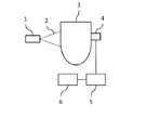
図1は、本実施形態に係る分光情報取得装置の模式図である。本実施形態における分光情報取得装置は、被検体に少なくとも2種類以上の波長のパルス光を照射する光照射部1、受信部4、パルス形状差補正部5、分光情報取得部6を含む。測定対象は被検体3であり、その内側には光吸収係数分布や光散乱係数分布が存在する。光音響イメージングにおいて生体を被験体とする場合、生体組織に含まれるヘモグロビン、それを含む血管、多くの新生血管を伴う腫瘍などが光吸収体として好適である。
<Embodiment of the present invention>
(Outline of device configuration)
FIG. 1 is a schematic diagram of a spectral information acquisition device according to this embodiment. The spectroscopic information acquisition apparatus according to the present embodiment includes a
照射部1は、パルス光を発する光源と、発せられたパルス光を被検体に照射する照射光学系からなる。パルス光は、照射パルス光2として被検体3に照射される。被検体内部に入った照射パルス光2は被検体内部で拡散・吸収される。その結果、発生した信号は被検体内部を伝搬し、受信部4で検出され、アナログの電気信号に変換される。電気信号はさらに増幅や、デジタル変換を施されたのち、受信データとしてメモリ(不図示)に格納される。
The
パルス形状差補正部5(補正部)は、予め測定した各波長のパルス形状やパルス幅、各波長のパルス形状を鑑みた受信部のインパルス応答にしたがって、各波長の受信データ間のパルス形状差に起因した差異を吸収するための補正を行う。パルス形状は、光パルスの時間強度変化、すなわち時間に応じた強度の変化を表す。さらに分光情報取得部6(情報取得部)は、補正された受信データを使って、各波長の吸収係数や散乱係数を算出し、それらの波長間の比から分光情報を算出する。 The pulse shape difference correction unit 5 (correction unit) determines the pulse shape difference between the reception data of each wavelength according to the pulse shape and pulse width of each wavelength measured in advance and the impulse response of the reception unit in consideration of the pulse shape of each wavelength. Make a correction to absorb the difference caused by. The pulse shape represents a temporal intensity change of the light pulse, that is, a change in intensity with time. Further, the spectral information acquisition unit 6 (information acquisition unit) calculates the absorption coefficient and the scattering coefficient of each wavelength using the corrected reception data, and calculates the spectral information from the ratio between the wavelengths.
(照射部)
照射部1は光源と照射光学系からなる。光源には、5ナノ秒乃至50ナノ秒のパルス光を発生可能なものが好ましい。光源としては大きな出力が得られるレーザーが好ましい。ただし、発光ダイオードやフラッシュランプなども利用できる。レーザーとしては、固体
レーザー、ガスレーザー、色素レーザー、半導体レーザーなど様々なレーザーを使用できる。理想的には、出力が強く連続的に波長を変えられる、Nd:YAG励起のTi:sa
レーザーや、アレキサンドライトレーザーがよい。異なる波長の単波長レーザーを複数保有していてもよい。
(Irradiation part)
The
A laser or an alexandrite laser is good. You may have a plurality of single wavelength lasers of different wavelengths.
光源から出射されたパルス光は、照射光学系を用いて被検体に照射される。照射光学系は、光を反射するミラー、光を拡大するレンズ、光を拡散させる拡散板などの光学部品である。照射光学系は、パルス光を所望の照射光分布形状に加工しながら被検体に導く。照射光学系には、光ファイバなど、光を伝搬させる導波路も含まれる。光源から発せられたパルス光が被検体3に所望の形状で照射されれば、どのような照射光学系を用いてもよい。なお、光はレンズで集光させるより、ある程度の面積に広げる方が被検体への安全性ならびに診断領域を広げられるという観点で好ましい。パルス光を被検体の広い領域に照射するために、光照射光学系に光照射部走査機構を設けてもよい。また、照射光学系が、照射位置を選択可能な複数の光出射口を有してもよい。
The pulsed light emitted from the light source is applied to the subject using the irradiation optical system. The irradiation optical system is an optical component such as a mirror that reflects light, a lens that magnifies the light, and a diffusion plate that diffuses the light. The irradiation optical system guides the pulsed light to the subject while processing it into a desired irradiation light distribution shape. The irradiation optical system also includes a waveguide that propagates light, such as an optical fiber. Any irradiation optical system may be used as long as the
(受信部)
受信部4は、被検体信号を物理的に受信する受信器と、信号処理機構とを有している。光音響装置の場合、被検体信号は被検体の表面及び内部で発生する光音響波であり、受信部は音響波を検出してアナログ信号である電気信号に変換する音響波受信器である。音響波受信器として例えば、圧電現象を用いたトランスデューサ、光の共振を用いたトランスデューサ、容量の変化を用いたトランスデューサなどを利用できる。
(Receiver)
The receiving
なお、複数の位置で音響波を検出するために、音響波受信素子が1次元または2次元に並べて複数配列されたアレイ探触子や、半球状の容器の内周面に音響波検出素子が複数配列された3次元探触子を用いることが好ましい。また、受信器と被検体の相対位置を変化させるための機械的な走査機構を備えることが好ましい。これらの構成により、被検体の広い位置を測定できるので、測定精度の向上、SN比の向上、測定時間の短縮などが期待できる。また、音響波発生源の位置が特定できるために、音響レンズでフォーカスされた単一素子でもよい。 In order to detect acoustic waves at a plurality of positions, an array probe in which a plurality of acoustic wave receiving elements are arranged one-dimensionally or two-dimensionally or an acoustic wave detecting element is provided on the inner peripheral surface of a hemispherical container. It is preferable to use a plurality of three-dimensional probes arranged. Further, it is preferable to provide a mechanical scanning mechanism for changing the relative position between the receiver and the subject. With these configurations, it is possible to measure a wide position of the subject, so that it is expected that the measurement accuracy is improved, the SN ratio is improved, and the measurement time is shortened. Further, since the position of the acoustic wave generation source can be specified, a single element focused by an acoustic lens may be used.
一方、拡散光などを用いる装置における被検体信号は、被検体から伝搬する、照射部が照射した照射パルス光と同じ波長または異なる波長の光である。受信部は、被検体信号である光を検出し、アナログ信号である電気信号に変換する光検出器である。例えば、光電効果を用いたフォトマルチプライヤーや半導体フォトダイオード、熱効果を用いた焦電検出器、ゴーレイセル、ボロメータなどを利用できる。 On the other hand, an object signal in an apparatus using diffused light or the like is light propagating from the object and having the same wavelength as or a different wavelength from the irradiation pulse light emitted by the irradiation unit. The reception unit is a photodetector that detects light that is a subject signal and converts the light into an electrical signal that is an analog signal. For example, a photomultiplier using a photoelectric effect, a semiconductor photodiode, a pyroelectric detector using a thermal effect, a Golay cell, a bolometer, or the like can be used.
信号処理機構は、受信器で得られた電気信号を増幅し、その電気信号をアナログ信号からデジタル信号に変換する。典型的には増幅器、A/D変換器、FPGA(Field Programmable Gate Array)チップなどで構成される。音響波受信器や光受信器から得られる検出信号が複数の場合は、処理時間短縮のため、同時に複数の信号を処理できることが望ましい。また被検体に対して同じ位置で受信した受信信号を積算して一つの信号にしてもよい。積算の方法は、信号同士の単純な積算、信号の平均値の取得、重み付けした信号の足し合わせなど様々である。なお、本明細書における「受信信号」とは、音響波受信器または光検出器から出力されるアナログ信号も、その後AD変換されたデジタル信号も含む概念である。 The signal processing mechanism amplifies the electric signal obtained by the receiver and converts the electric signal from an analog signal to a digital signal. Typically, it is composed of an amplifier, an A / D converter, an FPGA (Field Programmable Gate Array) chip, and the like. When there are a plurality of detection signals obtained from the acoustic wave receiver and the optical receiver, it is desirable to be able to process a plurality of signals at the same time in order to shorten the processing time. Further, received signals received at the same position with respect to the subject may be integrated into one signal. There are various integration methods such as simple integration of signals, acquisition of an average value of signals, and addition of weighted signals. The “received signal” in this specification is a concept that includes both an analog signal output from an acoustic wave receiver or a photodetector and a digital signal that is AD-converted thereafter.
(パルス形状差補正部)
本実施形態では、パルス光の波長ごとに時系列の受信信号が得られる。パルス形状差補正部5は、これら複数の受信信号から、波長間のパルス形状の違いが及ぼす影響を低減するような補正を行い、補正受信信号を取得する。すなわち、パルス形状差補正部5は、複
数の受信信号のパルス幅の差が小さくなるような補正を行い、補正受信信号を取得する。パルス形状差補正部は、プログラムやFPGAチップとして前記信号処理機構に含まれていてもよいし、後述する分光情報取得部であるワークステーションにプログラムとして含まれてもよい。受信信号の波長間のパルス形状の違いが及ぼす影響を低減するような補正が可能であれば、どのような補正方法でも良い。
(Pulse shape difference correction unit)
In the present embodiment, time-series reception signals are obtained for each wavelength of pulsed light. The pulse shape
(信号の補正方法)
次に、パルス形状差補正部が行う、受信信号波長間でのパルス形状差を補正する方法について述べる。N個の波長(波長1〜n)で測定した場合の、それぞれの波長におけるパルス形状を、P1(t)〜Pn(t)とする。ここで、tは時間である。予め、オシロスコープなどで波長ごとの光パルス形状を測定しておくことが望ましい。パルス形状が完全に測定できなくても、パルス幅が分かる測定だけでも良い。パルスは、典型的にはデルタ型の短パルス光であるが、これに限られない。また、各波長の光を用いて被検体を測定することで得られる受信信号をそれぞれ、S1(t)〜Sn(t)とする。以下に、5つの補正手法を説明する。
(Signal correction method)
Next, a method of correcting the pulse shape difference between the reception signal wavelengths performed by the pulse shape difference correction unit will be described. The pulse shapes at the respective wavelengths when measured at N wavelengths (
(補正方法1)第一に、ある基準となる波長のパルス形状に対して、他の波長の受信信号を補正する手法について述べる。基準波長をk番目とすると、基準となる波長のパルス形状はPk(t)、基準波長のパルス光に由来する信号はSk(t)となる。基準となる波長はどれでも良い。ただし、補正の際にノイズなどをあげてしまわないように、もっともパルス幅の大きい波長を選択することが望ましい。 (Correction Method 1) First, a method for correcting a received signal of another wavelength with respect to a pulse shape of a certain reference wavelength will be described. When the reference wavelength is k-th, the pulse shape of the reference wavelength is Pk (t), and the signal derived from the pulsed light of the reference wavelength is Sk (t). Any reference wavelength may be used. However, it is desirable to select the wavelength with the largest pulse width so that noise or the like is not raised during correction.
ここで、n番目(n≠k)の受信信号を補正する方法について述べる。n番目のパルス形状をPn(t)、k番目とn番目のパルス形状をフーリエ変換したものをそれぞれ、FT(Pk(t))、FT(Pn(t))とする。関数FT(x)はxをフーリエ変換する関数である。さらに受信信号Sn(t)をフーリエ変換したものはFT(Sn(t))となる。信号Sn(t)を、基準となるk番目の波長のパルス形状Pk(f)とn番目の波長のパルス形状Pn(f)を用いて補正すると、補正済み受信信号は次式(1)のような、周波数領域を用いた演算により取得される。

SNはノイズの閾値で、ノイズの上げすぎや、ゼロ除算を抑制する項である。またiFT[x]はxを逆フーリエ変換する関数である。k番目以外の受信信号S1(t)〜Sn(t)に式(1)を適用することにより、corr1(S1(t))〜corr1(Sn(t))を取得する。
Here, a method of correcting the n-th (n ≠ k) received signal will be described. The n-th pulse shape is Pn (t), and the Fourier transforms of the k-th and n-th pulse shapes are FT (Pk (t)) and FT (Pn (t)), respectively. The function FT (x) is a function that Fourier transforms x. Further, the Fourier transform of the received signal Sn (t) becomes FT (Sn (t)). When the signal Sn (t) is corrected using the pulse shape Pk (f) of the k-th wavelength and the pulse shape Pn (f) of the n-th wavelength, which are the reference, the corrected reception signal is expressed by the following equation (1). It is acquired by such calculation using the frequency domain.
SN is a threshold value of noise, which is a term for suppressing excessive noise and division by zero. Further, iFT [x] is a function for performing an inverse Fourier transform on x. By applying the equation (1) to the received signals S1 (t) to Sn (t) other than the k-th signal, corr1 (S1 (t)) to corr1 (Sn (t)) are acquired.
(補正方法2)第二に、ある基準となる波長のパルス幅に対して、他の波長の受信信号を補正する別の手法について述べる。基準となる波長をk番目とすると、基準となる波長のパルス形状はPk(t)となる。このパルス形状をガウス関数で近似したものをG(Pk(t))とし、その半値幅をHWG(Pk(t))とする。この半値幅HWG(Pk(t))をk番目の波長のパルス幅とする。ここではガウス関数で近似したが、パルス形状Pk(t)を近似できる関数であれば何でもよい。 (Correction Method 2) Secondly, another method for correcting a received signal of another wavelength with respect to a pulse width of a certain reference wavelength will be described. When the reference wavelength is k-th, the pulse shape of the reference wavelength is Pk (t). Let G (Pk (t)) be an approximation of this pulse shape with a Gaussian function, and its half-value width be HWG (Pk (t)). This half value width HWG (Pk (t)) is the pulse width of the kth wavelength. Although a Gaussian function is used for approximation here, any function that can approximate the pulse shape Pk (t) may be used.
また、基準となる波長は、パルス幅が一番大きい波長がもっともよい。なぜならば、基
準となる波長よりも短いパルス幅の波長の信号を補正する場合は、ぼかす、または、ガウス関数をコンボリューションすることで対応できるからである。一方、基準となる波長よりも長いパルス幅の波長の信号を補正する場合は、デコンボリューションする必要があり、ノイズを上げてしまう可能性が大きい。その他の波長についてもガウス関数で近似したものをそれぞれG(P1(t))〜G(Pn(t))、その半値幅をHWG(P1(t)〜HWG(Pn(t))とする。各波長の近似パルス幅から、補正パルス幅は、次式(2)により算出される。
半値幅cHWG(Pn(t))で中心値0の正規分布関数をNDF(cHWG(Pn(t)))とすると、下式(3)により受信信号の波長間パルス形状差が補正される。
(補正方法3)第三に、すべての信号から、各波長のパルス形状の影響を差し引く手法について述べる。補正された各波長の補正信号をcorr3(S1(t))〜corr3(Sn(t))とする。下式(4)により、各波長において、受信信号の波長間パルス形状差が補正される。
(補正方法4)第四に、すべての信号から、各波長のパルス幅の影響を差し引く別の手法について述べる。各波長のパルス形状をガウス関数で近似したものをG(P1(t))〜G(Pn(t))とする。また、補正された各波長の補正信号をcorr4(S1(t))〜corr4(Sn(t))とする。下式(5)により、各波長において、受信信号の波長間パルス幅差が補正される。
(補正方法5)第五に、予め各波長でパルス形状の影響も含めた検出器のインパルス応答を測定し、それらのインパルス応答を使い、各波長の受信信号を補正する手法について述べる。各波長におけるパルス形状の影響も含めた検出器のインパルス応答をIR1(t)〜IRn(t)、補正された各波長の補正信号をcorr5(S1(t))〜corr5(Sn(t))とする。下式(6)により、各波長において、受信信号のインパルス応答兼パルス形状が補正される。インパルス応答は、予め測定し、テーブルや数式の形式でメモリに保存しておくことが好ましい。
(分光情報取得部)
図1に戻って説明を続ける。分光情報取得部6は、光量分布の算出や画像再構成などを行うことにより、被検体内部の分光情報を取得する。分光情報取得部として、CPUやメモリなどの演算資源を備えるPCやワークステーションが好適である。画像再構成処理は、予めプログラミングされたソフトウェアに従って行われる。
(Spectroscopic information acquisition unit)
Returning to FIG. 1, the description will be continued. The spectroscopic
分光情報取得部6は、パルス形状差補正部により補正された受信信号を使って初期音圧分布P0(r)を算出する。初期音圧分布の算出方法は、ユニバーサルバックプロジェクション(UBP)法でも、整相加算(Delay and Sum)でも、繰り返し逆問題手法でも、モデルベース再構成でも良い。波長間で定量性を損なわなければどのようの方法でもよい。
The spectral
分光情報取得部6はさらに、各波長の照射時の被検体内部の光量分布Φ(r)を算出し、P0(r)からグルナイゼン係数も含めて除算することにより吸収係数分布μa(r)を各波長で算出する。また、各波長の吸収係数分布を用いて、成分濃度分布や酸素飽和度分布を算出する。
The spectral
<処理手順>
本実施形態の分光情報取得方法を、図2のフローチャートを用いて説明する。
<Processing procedure>
The spectral information acquisition method of this embodiment will be described with reference to the flowchart of FIG.
(ステップS11:照射工程)
光照射部1が、少なくとも2波長以上のパルス光をそれぞれ被検体に照射する。
(Step S11: irradiation step)
The
(ステップS12:信号受信工程)
受信部4が、S11において被検体にパルス光が照射された結果、被検体から発生する信号(光または音響波)を受信する。光または音響波は電気信号に変換され、メモリなどに格納される。
(Step S12: signal receiving step)
The receiving
(ステップS13:信号補正工程)
パルス形状差補正部5が、S12において受信した各波長の受信信号を、各波長のパルス形状差に従って補正し、補正受信信号を取得する。
(Step S13: signal correction process)
The pulse shape
(ステップS14:分光データ算出工程)
分光情報取得部6が、S13において算出された補正受信信号を使い、各波長における初期音圧分布や吸収係数分布などの特性情報を算出する。また、処理の内容によっては、複数の波長における特性情報を用いて、最終的な分光情報(酸素飽和度分布など)を算出する。
(Step S14: Spectral data calculation step)
The spectral
上記フローの分光情報取得方法によれば、ステップS13において複数の波長のパルス形状の相違が補正された補正受信信号が取得される。その結果、ステップS14で生成される画像データの精度や分解能が向上する。 According to the spectral information acquisition method of the above flow, the corrected reception signal in which the differences in the pulse shapes of the plurality of wavelengths are corrected in step S13 is acquired. As a result, the accuracy and resolution of the image data generated in step S14 are improved.
<実施例1>
続いて、より具体的な実施例を説明する。まず実施例1では、お椀型の探触子で人間の乳房を測定し、乳房内部の血管情報や、血液の酸素飽和度分布を取得するPAT診断装置
について述べる。実施例1での信号補正は、パルス幅差に基づく補正処理である。
<Example 1>
Next, more specific examples will be described. First, in the first embodiment, a PAT diagnostic apparatus that measures a human breast with a bowl-shaped probe and acquires blood vessel information inside the breast and oxygen saturation distribution of blood will be described. The signal correction in the first embodiment is a correction process based on the pulse width difference.
(構成)
図3を用いて、本実施例の構成に関して説明する。アレキサンドライトレーザー11は、波長756nmと797nmのパルス光を出射する。パルス光は多関節アーム12を通って、照射光学系13に入り、ミラーとレンズと拡散板を通って拡大されて、被検体である人間の乳房16にパルス光14として照射される。アレキサンドライトレーザー11は照射部の光源に相当する。
(Constitution)
The configuration of this embodiment will be described with reference to FIG. The
お椀型探触子15は水で満たされており、乳房16は水に浸っている。乳房16から光音響効果により出てきた音響波は、お椀型探触子15上にフィボナッチ配列状に並んだ複数のピエゾ素子により受信され、電気信号に返還される。電気信号は、増幅処理とデジタル変換処理を施されて、データ取得システム17内部のメモリ(不図示)に格納される。お椀型探触子15は受信部に相当する。
The bowl-shaped
データ取得システム17内部のメモリに格納された各波長に由来する受信信号は、PC18を構成する波長間パルス幅差補正機構19において、所定のプログラムに従って波長間パルス幅差補正受信信号に変換される。波長間パルス幅差補正機構19は、予め測定された756nmと797nmの波長のパルス幅データを、メモリや外部装置などから取得し、補正に使用する。波長間パルス幅差補正機構19は、パルス形状差補正部に相当する。
The reception signal derived from each wavelength stored in the memory inside the
酸素飽和度算出機構20は、波長間パルス幅差補正受信信号を使って、ヘモグロビン濃度分布と酸素飽和度分布を算出する。PC18は、ヘモグロビン濃度分布を明度に、酸素飽和度分布を色相にそれぞれ割り当てた画像を、ディスプレイ21に表示させる。ここでは、ヘモグロビン濃度分布を明度に割り当てたが、明度・彩度・色相のどれかに割り当てられればよい。酸素飽和度算出機構20は、分光情報取得部に相当する。
The oxygen
(補正方法)
本実施例の波長間パルス幅差補正について詳しく述べる。波長756nmの光のパルス幅は60nsec、波長797nmの光のパルス幅は90nsecである。ここでいうパルス幅とは、各波長のパルス形状をガウス関数でフィッティングして、得られたガウス関数の半値幅である。ここでは、波長756nmの光に由来する受信信号S756(t)を、パルス幅が90nsecで照射したように補正したい。そのためには、半値幅√(90^2−60^2)=67nsecのガウス分布でぼかせばよい。
(Correction method)
The correction of the pulse width difference between wavelengths in this embodiment will be described in detail. The pulse width of light having a wavelength of 756 nm is 60 nsec, and the pulse width of light having a wavelength of 797 nm is 90 nsec. The pulse width here is the half-value width of the Gaussian function obtained by fitting the pulse shape of each wavelength with a Gaussian function. Here, it is desired to correct the received signal S 756 (t) derived from the light having the wavelength of 756 nm as if it were emitted with a pulse width of 90 nsec. For that purpose, the Gaussian distribution with the half width √ (90̂2-60̂2) = 67 nsec may be used for blurring.
なお、波長797nmの光に由来する受信信号S797(t)をパルス幅が60nsecのパルス光で取得したように補正してもよい。その場合、半値幅67nsecの半値幅のガウス関数でデコンボリューションする。ただし、デコンボリューションによるノイズの増加を可及的に抑制する必要がある。そのため、分光情報を取得するときに解像度よりも定量性を重視する場合、パルス幅の小さい方の波長の受信信号をパルス幅の大きい方の波長の受信信号に合わせる方が好ましい。そして、得られた分光情報をパルス幅の小さいほうの波長で得られた特性情報(例えば、初期音圧分布や吸収係数分布)を用いてマスキングすることにより定量性と解像度の両方が担保された分光情報を取得することができる。例えば、上述したようにパルス幅の小さいほうの波長で得られた特性情報の値を、分光情報の色相、彩度、明度のいずれかに割り当てることによりマスキングすることができる。 The received signal S 797 (t) derived from the light having the wavelength of 797 nm may be corrected so as to be acquired by the pulsed light having the pulse width of 60 nsec. In that case, deconvolution is performed with a Gaussian function having a full width at half maximum of 67 nsec. However, it is necessary to suppress the increase of noise due to deconvolution as much as possible. Therefore, when importance is attached to the quantitative property rather than the resolution when acquiring the spectral information, it is preferable to match the received signal of the wavelength having the smaller pulse width with the received signal of the wavelength having the larger pulse width. By masking the obtained spectral information with the characteristic information (for example, the initial sound pressure distribution or the absorption coefficient distribution) obtained at the smaller wavelength of the pulse width, both quantitativeness and resolution are secured. Spectral information can be acquired. For example, as described above, masking can be performed by assigning the value of the characteristic information obtained at the wavelength having the smaller pulse width to any one of the hue, the saturation, and the lightness of the spectral information.
(処理フロー)
本実施例の分光情報取得方法を、図4のフローチャートを用いて説明する。
(Processing flow)
The spectral information acquisition method of this embodiment will be described with reference to the flowchart of FIG.
(ステップS21)
2波長のパルス光を乳房に照射することにより光音響信号を取得する。すなわち、照射光学系13が、波長756nmと797nmそれぞれのパルス光14を乳房16に照射する。お椀型探触子15上に並んだピエゾ素子は、各波長の光に由来する光音響波を受信し、電気信号に変換してデータ取得システム17に格納する。
(Step S21)
A photoacoustic signal is acquired by irradiating the breast with pulsed light of two wavelengths. That is, the irradiation
(ステップS22)
各波長の受信信号を各波長のパルス幅に従って、パルス幅差補正する。すなわち、波長間パルス幅差補正機構19は、波長756nmと797nmそれぞれのパルス光のパルス幅に基づいて、補正受信信号を生成する。ここでは、パルス幅が比較的大きい波長797nmの側に、波長756nmの受信信号を合わせる。
(Step S22)
The pulse width difference of the received signal of each wavelength is corrected according to the pulse width of each wavelength. That is, the inter-wavelength pulse width
(ステップS23)
パルス幅差補正受信信号で吸収係数分布を算出し、さらに酸素飽和度分布を算出する。すなわち、酸素飽和度算出機構20は、波長756nmの光に由来する補正受信信号と、波長797nmの光に由来する受信信号それぞれに基づいて、UBP法を用いて初期音圧分布を算出する。具体的には、数式(μa=P0/ΓΦ)より、初期音圧分布から光量分布Φとグルナイゼン係数を除算する事で吸収係数を算出する。そして、波長756nmと797nmそれぞれにおける吸収係数分布から、ヘモグロビン濃度分布と酸素飽和度分布を算出する。PC18は、ヘモグロビン濃度分布を明度、酸素飽和度分布を色相に割り当てて、ヘモグロビン酸素飽和度分布として、ディスプレイ21に表示させる。
(Step S23)
The absorption coefficient distribution is calculated from the pulse width difference corrected reception signal, and further the oxygen saturation distribution is calculated. That is, the oxygen
本実施例の分光情報取得装置を用いた処理によれば、複数の波長の光を用いて物質濃度や酸素飽和度を取得する光音響装置において、波長ごとのパルス幅の違いを補正できる。その結果、被検体内部の特性情報分布を精度よく画像化できる。 According to the processing using the spectral information acquisition device of the present embodiment, it is possible to correct the difference in pulse width for each wavelength in the photoacoustic device that acquires the substance concentration and the oxygen saturation level by using the light of a plurality of wavelengths. As a result, the characteristic information distribution inside the subject can be accurately imaged.
<実施例2>
本実施例は、光フォーカス型光音響顕微鏡でマウスの脳を測定し、刺激によるマウスの脳の血液量や酸素飽和度変化を観察する装置について説明する。
<Example 2>
In this example, an apparatus for measuring a mouse brain with an optical focus type photoacoustic microscope and observing changes in blood volume and oxygen saturation of the mouse brain due to stimulation will be described.
(構成)
図5を用いて、本実施例の構成に関して説明する。Ti:saレーザー31は、756nm、780nm、797nm、825nmの4波長のパルス光を出射可能である。出射したパルス光は、光バンドルファイバ32を通って、照射光学系33に入る。パルス光は照射光学系33内のミラーやレンズを通ったのち、これらの波長の光に対して透明な音響ミラー42を透過し、マウスの脳36の内部へ集光する。Ti:saレーザー31は、照射部の光源に相当する。
(Constitution)
The configuration of this embodiment will be described with reference to FIG. The Ti:
マウスの脳36から発生した光音響波は、音響ミラー42で反射され、静電容量型の音響波探触子であるcMUT35で受信される。受信された信号は、電気信号に変換され、増幅されて、検出信号としてデータ取得システム37のメモリ39に格納される。このような光音響顕微鏡測定を各波長で実施することで、受信信号S756(t)、S780(t)、S797(t)、S825(t)が得られる。cMUT35は、受信部に相当する。
The photoacoustic wave generated from the
本実施例ではまた、あらかじめ厚さ30nmの薄膜を標準サンプルとして各波長で光音響測定しておく。これにより、cMUT35のインパルス応答と各波長のパルス形状の影響を含めた補正データIR(t)が取得できる。取得された補正データIR(t)は、メモリ39に保存しておく。本実施例では、この補正データIR(t)を用いて、第五の補
正方法により、補正受信信号を算出する。第五の補正方法を実行するパルス形状差補正部は、データ取得システム37とワークステーション38のどちらであってもよい。
In the present embodiment, the photoacoustic measurement is performed in advance at each wavelength using a thin film having a thickness of 30 nm as a standard sample. Thereby, the correction data IR (t) including the influence of the impulse response of the
算出された補正受信信号を転送されたワークステーション38の酸素飽和度算出機構40は、あらかじめ実装されたプログラムにより補正受信信号から酸素飽和度やヘモグロビン濃度を算出する。算出された酸素飽和度分布とヘモグロビン濃度分布や、それらの経時変化は、モニター41に表示される。酸素飽和度算出機構40は、分光情報取得部に相当する。
The oxygen
(処理フロー)
本実施例の分光情報取得方法を説明する。本実施例のフローは、基本的に図4と同様である。ステップS21では、波長756nm、780nm、797nm、825nmのパルス光34がそれぞれマウスの脳36に照射される。cMUT35は各波長に由来する光音響波を受信し、データ取得システム37のメモリ39に受信信号を格納する。ステップS22では、各波長のパルス光のパルス形状の影響も含めたインパルス応答を用いて、各波長の受信信号からインパルス応答をデコンボリューションする。これにより、波長間パルス形状差補正され、補正受信信号を取得できる。ステップS23では、酸素飽和度算出機構40が、各波長での補正受信信号を用いて酸素飽和度分布とヘモグロビン濃度分布を算出し、ディスプレイ41に表示する。
(Processing flow)
The spectral information acquisition method of this embodiment will be described. The flow of this embodiment is basically the same as that of FIG. In step S21, the pulsed light 34 having wavelengths of 756 nm, 780 nm, 797 nm, and 825 nm is applied to the
本実施例によれば、複数の波長の光を用いる光音響顕微鏡においても、波長ごとのパルス幅の違いを補正して被検体内部の特性情報分布を精度よく画像化できるようになる。本実施例の手法は、光をフォーカスする光学部材を備える光フォーカス型の顕微鏡にも、光音響波をフォーカスする音響部材を備える音響フォーカス型の顕微鏡にも適用できる。 According to the present embodiment, even in a photoacoustic microscope using light of a plurality of wavelengths, it is possible to correct the difference in pulse width for each wavelength and accurately image the characteristic information distribution inside the subject. The method of this embodiment can be applied to an optical focus type microscope including an optical member for focusing light and an acoustic focus type microscope including an acoustic member for focusing a photoacoustic wave.
<実施例3>
本実施例は、時間分解拡散光トモグラフィー装置について説明する。これは、人間の乳房などの内部の、ヘモグロビン濃度分布、ヘモグロビンの酸素飽和度分布、水や脂肪の分布を測定する装置である。
<Example 3>
This example describes a time-resolved diffuse optical tomography device. This is a device for measuring the hemoglobin concentration distribution, the hemoglobin oxygen saturation distribution, the water and fat distribution inside the human breast.
図6を用いて、本実施例の構成に関して説明する。Ti:saレーザー51は、波長750〜850nmのパルス光を連続的に出射できる。波長としては近赤外領域が好適であるが、これに限られない。出射されたパルス光は光ファイバ52を通って、複数の出射口53のうち一か所から乳房56へパルス光54として出射される。パルス光54は、乳房56内部で吸収および散乱され、乳房組織を伝搬して、複数のフォトマル55(光電子増倍管)によって検出される。受信信号は増幅処理を経て信号取得システム57のメモリに格納される。Ti:saレーザー51は、照射部の光源に相当する。
The configuration of this embodiment will be described with reference to FIG. The Ti:
PC58のパルス形状差補正機構59は、各波長のパルス形状を用いて、メモリ内の受信信号を補正受信信号に変換する。予め、出射口53とフォトマル55を直接光ファイバなどでつないで各波長のパルス形状は取得し、PCのメモリに格納しておくことが好ましい。成分濃度分布算出機構60は、補正受信信号を用いた逆問題解析により、乳房56内部の水分濃度分布や、脂肪濃度分布、ヘモグロビン濃度分布、ヘモグロビンの酸素飽和度分布を算出する。成分濃度分布算出機構60は、分光情報取得部に相当する。
The pulse shape
本実施例の分光情報取得方法を、図7のフローチャートを用いて説明する。 The spectral information acquisition method of this embodiment will be described with reference to the flowchart of FIG.
(ステップS31)
各波長のパルス光を照射することにより得られた光受信信号を取得する。すなわち、波長750〜850nmのパルス光54を、1nm刻みで乳房56に照射する。光検出素子
であるフォトマル55は、受信信号をデータ取得システム57に格納する。
(Step S31)
An optical reception signal obtained by irradiating pulsed light of each wavelength is acquired. That is, the
(ステップS32)
光受信信号を各波長のパルス波形で補正する。すなわち、あらかじめ測定しておいた波長750〜850nmのパルス光のパルス形状を用いて、各波長での受信信号にデコンボリューション処理を施す。これにより、波長間パルス形状差が補正された、補正受信信号が取得できる。
(Step S32)
The optical reception signal is corrected by the pulse waveform of each wavelength. That is, the received signal at each wavelength is subjected to deconvolution processing by using the pulse shape of the pulsed light having a wavelength of 750 to 850 nm measured in advance. As a result, a corrected reception signal in which the pulse shape difference between wavelengths is corrected can be acquired.
(ステップS33)
成分分布を算出する。すなわち、補正受信信号を使った逆問題解析により、被検体内部のヘモグロビン濃度やヘモグロビンの酸素飽和度、水や脂肪の濃度分布を算出し、ディスプレイ61に表示する。
(Step S33)
Calculate the component distribution. That is, the hemoglobin concentration inside the subject, the oxygen saturation level of hemoglobin, and the concentration distribution of water and fat are calculated by the inverse problem analysis using the corrected reception signal, and displayed on the
本実施例によれば、複数の波長による拡散光トモグラフィーを用いた分光情報取得装置において、波長ごとのパルス形状の違いを補正して被検体内部の特性情報分布を精度よく画像化できる。 According to the present embodiment, in the spectral information acquisition apparatus using diffused optical tomography with a plurality of wavelengths, it is possible to correct the difference in pulse shape for each wavelength and accurately image the characteristic information distribution inside the subject.
(その他の実施例)
本発明は、上述の実施形態の1以上の機能を実現するプログラムを、ネットワーク又は記憶媒体を介してシステム又は装置に供給し、そのシステム又は装置のコンピュータにおける1つ以上のプロセッサがプログラムを読出し実行する処理でも実現可能である。また、1以上の機能を実現する回路(例えば、ASIC)によっても実現可能である。
(Other embodiments)
The present invention supplies a program that implements one or more functions of the above-described embodiments to a system or apparatus via a network or a storage medium, and one or more processors in a computer of the system or apparatus read and execute the program. It can also be realized by the processing. It can also be realized by a circuit (for example, ASIC) that realizes one or more functions.
1:照射部、2:照射パルス光、3:被検体、4:受信部、5:受信データ波長間パルス形状差補正、6:分光情報取得部 1: irradiation unit, 2: irradiation pulsed light, 3: subject, 4: reception unit, 5: correction of pulse shape difference between reception data wavelengths, 6: spectroscopic information acquisition unit
Claims (17)
前記複数の波長のそれぞれのパルス光のパルス形状に応じて、前記複数の受信信号の少なくともいずれかを補正する補正部と、
前記補正部により補正された前記複数の受信信号を用いて、前記被検体の分光情報を取得する情報取得部と、
を有し、
前記補正部は、前記複数の波長(波長1〜n)のそれぞれのパルス光の前記パルス形状をP1(t)〜Pn(t)とし、前記複数の受信信号をS1(t)〜Sn(t)としたとき、前記複数の波長のうち基準波長の前記パルス光の前記パルス形状と、他の波長の前記パルス光の前記パルス形状の違いが、前記複数の受信信号に及ぼす影響を低減するような補正を行い、
前記補正部は、前記他の波長の前記パルス光に由来する前記受信信号に、前記基準波長の前記パルス光の前記パルス形状および前記他の波長の前記パルス光の前記パルス形状を用いた演算を行うことにより前記補正を行う
ことを特徴とする被検体情報取得装置。 In a subject information acquisition device for processing a plurality of received signals corresponding to the plurality of wavelengths obtained by receiving a subject signal propagating from a subject irradiated with pulsed light of each of a plurality of different wavelengths There
Depending on the pulse shape of each pulsed light of the plurality of wavelengths, a correction unit that corrects at least one of the plurality of received signals,
Using the plurality of reception signals corrected by the correction unit, an information acquisition unit that acquires the spectral information of the subject,
Have a,
The correction unit sets the pulse shapes of the pulsed lights of the plurality of wavelengths (wavelengths 1 to n) to P1 (t) to Pn (t) and sets the plurality of received signals to S1 (t) to Sn (t). ), The difference between the pulse shape of the pulsed light of the reference wavelength of the plurality of wavelengths and the pulse shape of the pulsed light of other wavelengths, to reduce the influence on the plurality of received signals. Correction,
The correction unit, in the received signal derived from the pulsed light of the other wavelength, an operation using the pulse shape of the pulsed light of the reference wavelength and the pulse shape of the pulsed light of the other wavelength. The subject information acquisition apparatus, wherein the correction is performed by performing the correction .
前記複数の波長のそれぞれのパルス光のパルス形状に応じて、前記複数の受信信号の少なくともいずれかを補正する補正部と、 Depending on the pulse shape of each pulsed light of the plurality of wavelengths, a correction unit that corrects at least one of the plurality of received signals,
前記補正部により補正された前記複数の受信信号を用いて、前記被検体の分光情報を取得する情報取得部と、 Using the plurality of reception signals corrected by the correction unit, an information acquisition unit that acquires the spectral information of the subject,
を有し、Have
前記補正部は、前記複数の波長(波長1〜n)のそれぞれのパルス光の前記パルス形状をP1(t)〜Pn(t)とし、前記複数の受信信号をS1(t)〜Sn(t)としたと The correction unit sets the pulse shapes of the pulsed lights of the plurality of wavelengths (wavelengths 1 to n) to P1 (t) to Pn (t) and sets the plurality of received signals to S1 (t) to Sn (t). )
き、前記複数の波長のうち基準波長の前記パルス光の前記パルス形状と、他の波長の前記パルス光の前記パルス形状の違いが、前記複数の受信信号に及ぼす影響を低減するような補正を行い、Of the plurality of wavelengths, the difference between the pulse shape of the pulsed light of the reference wavelength and the pulsed light of the other wavelength, the correction to reduce the influence on the plurality of received signals. Done,
前記補正部は、前記パルス形状として前記パルス光のパルス幅を利用するものであり、前記基準波長は、前記複数の波長のうち前記パルス幅がもっとも大きい波長である The correction unit uses the pulse width of the pulsed light as the pulse shape, and the reference wavelength is a wavelength having the largest pulse width among the plurality of wavelengths.
ことを特徴とする被検体情報取得装置。A subject information acquisition apparatus characterized by the above.
ことを特徴とする請求項2に記載の被検体情報取得装置。 If the received signal derived from the pulsed light of the other wavelength is the pulse width of the pulsed light of the other wavelength is the pulse width of the pulsed light of the reference wavelength. The subject information acquiring apparatus according to claim 2 , wherein the correction is performed so as to obtain a shape obtained in the above.
前記他の波長の前記パルス光に対応する前記受信信号に基づいて前記被検体の特性情報を取得し、
前記特性情報を用いて前記分光情報をマスキングする
ことを特徴とする請求項3に記載の被検体情報取得装置。 The information acquisition unit,
Obtaining characteristic information of the subject based on the received signal corresponding to the pulsed light of the other wavelength,
The object information acquiring apparatus according to claim 3 , wherein the spectral information is masked by using the characteristic information.
ことを特徴とする請求項2ないし4のいずれか1項に記載の被検体情報取得装置。 Wherein the correction unit, subject information obtaining apparatus according to the pulse shape in any one of claims 2 to 4, characterized in that to obtain the pulse width by approximating a Gaussian function.
ことを特徴とする請求項1ないし5のいずれか1項に記載の被検体情報取得装置。 The subject information acquiring apparatus according to any one of claims 1 to 5 , wherein the subject signal is a photoacoustic wave propagating from the subject.
ことを特徴とする請求項1ないし6のいずれか1項に記載の被検体情報取得装置。 The subject signal according to any one of claims 1 to 6 , wherein the subject signal is light propagated through absorption and scattering in the subject after being irradiated with the pulsed light. Information acquisition device.
ことを特徴とする請求項1ないし7のいずれか1項に記載の被検体情報取得装置。 The subject information acquiring apparatus according to any one of claims 1 to 7 , wherein the information acquisition unit acquires the oxygen saturation of the subject as the spectral information.
ことを特徴とする請求項1ないし8のいずれか1項に記載の被検体情報取得装置。 The object information acquiring apparatus according to any one of claims 1 to 8 , wherein the pulse shape indicates a temporal intensity change of the pulsed light.
ことを特徴とする請求項1ないし9のいずれか1項に記載の被検体情報取得装置。 Wherein the correction unit is configured from a plurality of received signals by subtracting the influence of the pulse shape of each pulse light of the plurality of wavelengths, either one of claims 1 to 9, characterized in that the correction 1 The subject information acquisition apparatus according to the item.
ことを特徴とする請求項1ないし10のいずれか1項のいずれか1項に記載の被検体情報取得装置。 The subject information acquiring apparatus according to any one of claims 1 to 10 , wherein the correction unit performs the correction in a frequency domain.
ことを特徴とする請求項1ないし11のいずれか1項に記載の被検体情報取得装置。 The correction unit performs the correction so as to reduce a difference between pulse widths of the plurality of reception signals, which is caused by the pulse shapes of the pulsed lights of the plurality of wavelengths. The subject information acquisition apparatus according to any one of 1 to 11 .
前記被検体信号を受信することにより前記複数の受信信号に変換する受信部と、
を有することを特徴とする請求項1ないし12のいずれか1項に記載の被検体情報取得装
置。 An irradiation unit for irradiating the subject with each pulsed light of the plurality of wavelengths,
A receiver that converts the subject signal into the plurality of received signals,
The subject information acquiring apparatus according to any one of claims 1 to 12 , further comprising:
ことを特徴とする請求項13に記載の被検体情報取得装置。 The subject information acquiring apparatus according to claim 13 , wherein the correction unit acquires the impulse response of the reception unit with respect to each pulsed light of the plurality of wavelengths and uses the impulse response for the correction.
前記複数の波長のそれぞれのパルス光のパルス形状に応じて、前記複数の受信信号の少なくともいずれかを補正するステップと、
前記補正するステップで補正された前記複数の受信信号を用いて、前記被検体の分光情報を取得するステップと、
を有し、
前記補正するステップは、前記複数の波長(波長1〜n)のそれぞれのパルス光の前記パルス形状をP1(t)〜Pn(t)とし、前記複数の受信信号をS1(t)〜Sn(t)としたとき、前記複数の波長のうち基準波長の前記パルス光の前記パルス形状と、他の波長の前記パルス光の前記パルス形状の違いが、前記複数の受信信号に及ぼす影響を低減するような補正を行い、
前記補正するステップは、前記他の波長の前記パルス光に由来する前記受信信号に、前記基準波長の前記パルス光の前記パルス形状および前記他の波長の前記パルス光の前記パルス形状を用いた演算を行うことにより前記補正を行う
ことを特徴とする信号処理方法。 A signal processing method for processing a plurality of received signals corresponding to the plurality of wavelengths obtained by receiving a subject signal propagating from a subject irradiated with pulsed light of each of a plurality of different wavelengths, ,
Depending on the pulse shape of the respective pulsed light of the plurality of wavelengths, a step of correcting at least one of the plurality of received signals,
Using the plurality of reception signals corrected in the correcting step, obtaining spectral information of the subject,
Have a,
In the correcting step, the pulse shapes of the pulsed lights of the plurality of wavelengths (wavelengths 1 to n) are set to P1 (t) to Pn (t), and the plurality of received signals are set to S1 (t) to Sn ( t), the influence of the difference between the pulse shape of the pulsed light of the reference wavelength and the pulse shape of the pulsed light of another wavelength on the plurality of received signals is reduced. Make a correction like
The step of correcting, in the received signal derived from the pulsed light of the other wavelength, the calculation using the pulse shape of the pulsed light of the reference wavelength and the pulse shape of the pulsed light of the other wavelength The signal processing method is characterized in that the correction is performed by performing .
前記複数の波長のそれぞれのパルス光のパルス形状に応じて、前記複数の受信信号の少なくともいずれかを補正するステップと、 Depending on the pulse shape of the respective pulsed light of the plurality of wavelengths, a step of correcting at least one of the plurality of received signals,
前記補正するステップで補正された前記複数の受信信号を用いて、前記被検体の分光情報を取得するステップと、 Using the plurality of reception signals corrected in the correcting step, obtaining spectral information of the subject,
を有し、Have
前記補正するステップは、前記複数の波長(波長1〜n)のそれぞれのパルス光の前記パルス形状をP1(t)〜Pn(t)とし、前記複数の受信信号をS1(t)〜Sn(t)としたとき、前記複数の波長のうち基準波長の前記パルス光の前記パルス形状と、他の波長の前記パルス光の前記パルス形状の違いが、前記複数の受信信号に及ぼす影響を低減するような補正を行い、 In the correcting step, the pulse shapes of the pulsed lights of the plurality of wavelengths (wavelengths 1 to n) are set to P1 (t) to Pn (t), and the plurality of received signals are set to S1 (t) to Sn ( t), the influence of the difference between the pulse shape of the pulsed light of the reference wavelength and the pulse shape of the pulsed light of another wavelength on the plurality of received signals is reduced. Make a correction like
前記補正するステップは、前記パルス形状として前記パルス光のパルス幅を利用するものであり、前記基準波長は、前記複数の波長のうち前記パルス幅がもっとも大きい波長である In the correcting step, the pulse width of the pulsed light is used as the pulse shape, and the reference wavelength is a wavelength having the largest pulse width among the plurality of wavelengths.
ことを特徴とする信号処理方法。A signal processing method characterized by the above.
A program that causes a computer to execute the signal processing method according to claim 15 .
Priority Applications (3)
| Application Number | Priority Date | Filing Date | Title |
|---|---|---|---|
| JP2016015107A JP6682282B2 (en) | 2016-01-29 | 2016-01-29 | Object information acquisition apparatus and signal processing method |
| US15/405,392 US20170215804A1 (en) | 2016-01-29 | 2017-01-13 | Object information acquiring apparatus and signal processing method |
| CN201710048413.0A CN107019493A (en) | 2016-01-29 | 2017-01-23 | Subject information acquisition device and signal processing method |
Applications Claiming Priority (1)
| Application Number | Priority Date | Filing Date | Title |
|---|---|---|---|
| JP2016015107A JP6682282B2 (en) | 2016-01-29 | 2016-01-29 | Object information acquisition apparatus and signal processing method |
Publications (3)
| Publication Number | Publication Date |
|---|---|
| JP2017131482A JP2017131482A (en) | 2017-08-03 |
| JP2017131482A5 JP2017131482A5 (en) | 2019-03-14 |
| JP6682282B2 true JP6682282B2 (en) | 2020-04-15 |
Family
ID=59385855
Family Applications (1)
| Application Number | Title | Priority Date | Filing Date |
|---|---|---|---|
| JP2016015107A Expired - Fee Related JP6682282B2 (en) | 2016-01-29 | 2016-01-29 | Object information acquisition apparatus and signal processing method |
Country Status (3)
| Country | Link |
|---|---|
| US (1) | US20170215804A1 (en) |
| JP (1) | JP6682282B2 (en) |
| CN (1) | CN107019493A (en) |
Families Citing this family (2)
| Publication number | Priority date | Publication date | Assignee | Title |
|---|---|---|---|---|
| WO2019171800A1 (en) * | 2018-03-05 | 2019-09-12 | 富士フイルム株式会社 | Photoacoustic device and method for controlling photoacoustic device |
| KR20200058948A (en) * | 2018-11-20 | 2020-05-28 | 삼성전자주식회사 | Spectrum measurement apparatus, method for correcting light source temperature change of spectrum, apparatus and method for estimating analyte concentration |
Family Cites Families (9)
| Publication number | Priority date | Publication date | Assignee | Title |
|---|---|---|---|---|
| JPH0698890A (en) * | 1992-09-18 | 1994-04-12 | Canon Inc | Optical ct apparatus |
| EP2957232A1 (en) * | 2009-10-29 | 2015-12-23 | Canon Kabushiki Kaisha | Photoacoustic apparatus |
| JP5661451B2 (en) * | 2010-12-27 | 2015-01-28 | キヤノン株式会社 | Subject information acquisition apparatus and subject information acquisition method |
| JP5939786B2 (en) * | 2011-02-10 | 2016-06-22 | キヤノン株式会社 | Acoustic wave acquisition device |
| JP6012216B2 (en) * | 2011-05-12 | 2016-10-25 | キヤノン株式会社 | Subject information acquisition apparatus and subject information acquisition method |
| EP2554115B1 (en) * | 2011-08-05 | 2015-02-25 | Canon Kabushiki Kaisha | Apparatus and method for acquiring information on subject |
| JP2013075000A (en) * | 2011-09-30 | 2013-04-25 | Fujifilm Corp | Photoacoustic image generating apparatus and method |
| JP2013128759A (en) * | 2011-11-22 | 2013-07-04 | Fujifilm Corp | Photoacoustic signal processing device and method |
| KR101620458B1 (en) * | 2014-07-04 | 2016-05-24 | 포항공과대학교 산학협력단 | Photo-acoustic image device and oxygen saturation measurement method |
-
2016
- 2016-01-29 JP JP2016015107A patent/JP6682282B2/en not_active Expired - Fee Related
-
2017
- 2017-01-13 US US15/405,392 patent/US20170215804A1/en not_active Abandoned
- 2017-01-23 CN CN201710048413.0A patent/CN107019493A/en active Pending
Also Published As
| Publication number | Publication date |
|---|---|
| US20170215804A1 (en) | 2017-08-03 |
| JP2017131482A (en) | 2017-08-03 |
| CN107019493A (en) | 2017-08-08 |
Similar Documents
| Publication | Publication Date | Title |
|---|---|---|
| US10342436B2 (en) | Object information acquiring apparatus and processing method | |
| JP6108705B2 (en) | Subject information acquisition apparatus and subject information acquisition method | |
| US9615751B2 (en) | Object information acquiring apparatus and object information acquiring method | |
| US20100087733A1 (en) | Biological information processing apparatus and biological information processing method | |
| US9737216B2 (en) | Object information acquiring apparatus and method for controlling object information acquiring apparatus | |
| US20120302866A1 (en) | Photoacoustic imaging apparatus and photoacoustic imaging method | |
| JP6012386B2 (en) | Subject information acquisition apparatus and control method thereof | |
| JP6461288B2 (en) | Biological information imaging apparatus, biological information analysis method, and biological information imaging method | |
| JP2017086172A (en) | Subject information acquisition device and control method thereof | |
| JP6682282B2 (en) | Object information acquisition apparatus and signal processing method | |
| JP2013215236A (en) | Subject information obtaining apparatus and subject information obtaining method | |
| JP6049780B2 (en) | Photoacoustic device | |
| CN104856728B (en) | Photo-acoustic device | |
| US9566006B2 (en) | Object information acquisition apparatus | |
| JP6664176B2 (en) | Photoacoustic apparatus, information processing method, and program | |
| JP2017006541A (en) | Subject information acquisition apparatus and subject information acquisition method | |
| JP2016000193A (en) | Subject information acquisition device and signal processing method | |
| JP6486056B2 (en) | Photoacoustic apparatus and processing method of photoacoustic apparatus | |
| JP2013103022A (en) | Acoustic wave acquisition device and control method of the same | |
| JP2017094169A (en) | Subject information acquisition device and subject information acquisition method | |
| JP2017035589A (en) | Photoacoustic apparatus | |
| JP2016093539A (en) | Subject information acquisition device and subject information acquisition method | |
| JP2017086173A (en) | Subject information acquisition device and control method thereof |
Legal Events
| Date | Code | Title | Description |
|---|---|---|---|
| RD02 | Notification of acceptance of power of attorney |
Free format text: JAPANESE INTERMEDIATE CODE: A7422 Effective date: 20181116 |
|
| A521 | Request for written amendment filed |
Free format text: JAPANESE INTERMEDIATE CODE: A523 Effective date: 20190124 |
|
| A621 | Written request for application examination |
Free format text: JAPANESE INTERMEDIATE CODE: A621 Effective date: 20190124 |
|
| A977 | Report on retrieval |
Free format text: JAPANESE INTERMEDIATE CODE: A971007 Effective date: 20191023 |
|
| A131 | Notification of reasons for refusal |
Free format text: JAPANESE INTERMEDIATE CODE: A131 Effective date: 20191112 |
|
| A521 | Request for written amendment filed |
Free format text: JAPANESE INTERMEDIATE CODE: A523 Effective date: 20200107 |
|
| TRDD | Decision of grant or rejection written | ||
| A01 | Written decision to grant a patent or to grant a registration (utility model) |
Free format text: JAPANESE INTERMEDIATE CODE: A01 Effective date: 20200225 |
|
| A61 | First payment of annual fees (during grant procedure) |
Free format text: JAPANESE INTERMEDIATE CODE: A61 Effective date: 20200325 |
|
| R151 | Written notification of patent or utility model registration |
Ref document number: 6682282 Country of ref document: JP Free format text: JAPANESE INTERMEDIATE CODE: R151 |
|
| LAPS | Cancellation because of no payment of annual fees |