JP6679355B2 - Electric toothbrush with lighting ring - Google Patents
Electric toothbrush with lighting ring Download PDFInfo
- Publication number
- JP6679355B2 JP6679355B2 JP2016051473A JP2016051473A JP6679355B2 JP 6679355 B2 JP6679355 B2 JP 6679355B2 JP 2016051473 A JP2016051473 A JP 2016051473A JP 2016051473 A JP2016051473 A JP 2016051473A JP 6679355 B2 JP6679355 B2 JP 6679355B2
- Authority
- JP
- Japan
- Prior art keywords
- electric toothbrush
- light emitting
- illumination ring
- toothbrush according
- emitting element
- Prior art date
- Legal status (The legal status is an assumption and is not a legal conclusion. Google has not performed a legal analysis and makes no representation as to the accuracy of the status listed.)
- Active
Links
- 238000005286 illumination Methods 0.000 claims description 55
- 241000904500 Oxyspora paniculata Species 0.000 claims description 9
- 230000001133 acceleration Effects 0.000 claims description 8
- 239000012780 transparent material Substances 0.000 claims description 2
- 210000003739 neck Anatomy 0.000 description 8
- 239000000463 material Substances 0.000 description 6
- 229920006324 polyoxymethylene Polymers 0.000 description 4
- 238000012856 packing Methods 0.000 description 3
- 230000002093 peripheral effect Effects 0.000 description 3
- 229920003002 synthetic resin Polymers 0.000 description 3
- 239000000057 synthetic resin Substances 0.000 description 3
- 238000013459 approach Methods 0.000 description 2
- 230000004397 blinking Effects 0.000 description 2
- 229930040373 Paraformaldehyde Natural products 0.000 description 1
- 208000005888 Periodontal Pocket Diseases 0.000 description 1
- 239000000853 adhesive Substances 0.000 description 1
- 230000001070 adhesive effect Effects 0.000 description 1
- 230000001680 brushing effect Effects 0.000 description 1
- 230000000295 complement effect Effects 0.000 description 1
- 239000002184 metal Substances 0.000 description 1
- 238000000465 moulding Methods 0.000 description 1
- -1 polyoxymethylene Polymers 0.000 description 1
- 230000005855 radiation Effects 0.000 description 1
- 230000000717 retained effect Effects 0.000 description 1
- 239000000758 substrate Substances 0.000 description 1
Images


Classifications
-
- A—HUMAN NECESSITIES
- A46—BRUSHWARE
- A46B—BRUSHES
- A46B15/00—Other brushes; Brushes with additional arrangements
- A46B15/0002—Arrangements for enhancing monitoring or controlling the brushing process
- A46B15/0038—Arrangements for enhancing monitoring or controlling the brushing process with signalling means
- A46B15/0044—Arrangements for enhancing monitoring or controlling the brushing process with signalling means with light signalling means
-
- A—HUMAN NECESSITIES
- A46—BRUSHWARE
- A46B—BRUSHES
- A46B15/00—Other brushes; Brushes with additional arrangements
- A46B15/0002—Arrangements for enhancing monitoring or controlling the brushing process
- A46B15/0016—Arrangements for enhancing monitoring or controlling the brushing process with enhancing means
- A46B15/0036—Arrangements for enhancing monitoring or controlling the brushing process with enhancing means with a lighting means, e.g. laser, bulb
-
- A—HUMAN NECESSITIES
- A61—MEDICAL OR VETERINARY SCIENCE; HYGIENE
- A61C—DENTISTRY; APPARATUS OR METHODS FOR ORAL OR DENTAL HYGIENE
- A61C17/00—Devices for cleaning, polishing, rinsing or drying teeth, teeth cavities or prostheses; Saliva removers; Dental appliances for receiving spittle
- A61C17/16—Power-driven cleaning or polishing devices
- A61C17/22—Power-driven cleaning or polishing devices with brushes, cushions, cups, or the like
- A61C17/221—Control arrangements therefor
-
- A—HUMAN NECESSITIES
- A61—MEDICAL OR VETERINARY SCIENCE; HYGIENE
- A61C—DENTISTRY; APPARATUS OR METHODS FOR ORAL OR DENTAL HYGIENE
- A61C17/00—Devices for cleaning, polishing, rinsing or drying teeth, teeth cavities or prostheses; Saliva removers; Dental appliances for receiving spittle
- A61C17/16—Power-driven cleaning or polishing devices
- A61C17/22—Power-driven cleaning or polishing devices with brushes, cushions, cups, or the like
- A61C17/225—Handles or details thereof
-
- A—HUMAN NECESSITIES
- A46—BRUSHWARE
- A46B—BRUSHES
- A46B2200/00—Brushes characterized by their functions, uses or applications
- A46B2200/10—For human or animal care
- A46B2200/1066—Toothbrush for cleaning the teeth or dentures
Description
この発明は電動歯ブラシの構造に関し、より詳しくはグリップ部分とブラシ部分とを有する電動歯ブラシに関する。 The present invention relates to an electric toothbrush structure, and more particularly to an electric toothbrush having a grip portion and a brush portion.
市場にある電動歯ブラシは、グリップ部分とブラシ部分とを有すると共に、表示部がグリップ部分に設けたものが知られている。又、市場にある電動歯ブラシは、ブラシ部分がグリップ部分に対し傾斜しているものがある。係る電動歯ブラシは、例えば特開2009−268828(米国特許公開公報2011−056033に対応)に記載されている。 BACKGROUND ART Electric toothbrushes on the market are known to have a grip portion and a brush portion, and a display portion provided in the grip portion. Further, in some electric toothbrushes on the market, the brush portion is inclined with respect to the grip portion. Such an electric toothbrush is described in, for example, Japanese Unexamined Patent Application Publication No. 2009-268828 (corresponding to US Patent Publication No. 2011-056033).
特許文献1によれば、表示部は電動歯ブラシの一方の側面、例えばブラシの毛先が存在する方の側面、に設けてあるので、電動歯ブラシを使用している者は、電動歯ブラシが所定の角度で保持されている場合にのみ、表示部を見る事ができる。電動歯ブラシを外方向に回して持つ場合、例えば歯の裏側を磨くために電動歯ブラシを持つ場合、使用者は表示部を見る事ができない。 According to Patent Document 1, since the display portion is provided on one side surface of the electric toothbrush, for example, the side surface where the bristle tips of the brush are present, a person who uses the electric toothbrush can obtain the predetermined electric toothbrush. You can see the display only if it is held at an angle. When the electric toothbrush is rotated outward and held, for example, when the electric toothbrush is held to brush the back side of the teeth, the user cannot see the display unit.
又、特許文献1によれば、ブラシ部分がグリップ部分に対し傾斜しているので、ブラシ部分とグリップ部分の間に掛かる張力は大きな値になる。特に、使用者が歯に対して強い圧力で保持すると、張力は大きくなる。特許文献1には、ブラシ部分とグリップ部分との間の接続構造については全く開示がない。 Further, according to Patent Document 1, since the brush portion is inclined with respect to the grip portion, the tension applied between the brush portion and the grip portion has a large value. In particular, when the user holds the tooth with a strong pressure, the tension increases. Patent Document 1 does not disclose any connection structure between the brush portion and the grip portion.
従来の電動歯ブラシは、上述したように、表示部を見る事ができない場合があると言う問題点を有する。本発明は、電動歯ブラシをどのような角度で持っても、使用者は常に見る事ができる様な表示部を有する電動歯ブラシを提供する事を目的とする。 As described above, the conventional electric toothbrush has a problem that the display part may not be visible. SUMMARY OF THE INVENTION It is an object of the present invention to provide an electric toothbrush which has a display unit which allows a user to always see the electric toothbrush at any angle.
本発明の電動歯ブラシは、長手のグリップ部分と長手のブラシ部分とを有する電動歯ブラシであって、グリップ部分とブラシ部分との間にリング状に存在し、発光可能な照明リングを備えた照明リングボディ、グリップ部分側に設けられ、光線を放出する発光素子、グリップ部分内に設けた回路基板であって、発光素子のオン・オフ制御を行う制御部を含む回路基板を含む。 The electric toothbrush of the present invention is an electric toothbrush having a long grip portion and a long brush portion, and is an illumination ring that is present in a ring shape between the grip portion and the brush portion and includes a lighting ring capable of emitting light. The circuit board includes a body, a light emitting element that emits a light beam on the grip portion side, and a circuit board provided in the grip portion, the circuit board including a control unit that controls ON / OFF of the light emitting element.
本発明の好ましい実施形態の電動歯ブラシにあっては、前記照明リングボディは、透明な材料で形成された中空の円筒型のボディ部と、ボディ部の内部に設けられ、開口を有する内部プレートとを有し、内部プレートより下側にあるボディ部はスカート壁を形成すると共に、前記照明リングは、ボディ部の外側にリング状に存在する。 In the electric toothbrush according to a preferred embodiment of the present invention, the lighting ring body includes a hollow cylindrical body portion formed of a transparent material, and an inner plate provided inside the body portion and having an opening. And the body portion below the inner plate forms a skirt wall, and the illumination ring is present in a ring shape outside the body portion.
本発明の好ましい実施形態の電動歯ブラシにあっては、前記回路基板は、長手基盤と、長手基盤に設けられた発光素子実装基板とを有し、発光素子実装基板の上に、上記発光素子が配置され、発光素子からの光線は、長手のグリップ部の軸方向に放出する。 In the electric toothbrush according to a preferred embodiment of the present invention, the circuit board has a longitudinal base and a light emitting element mounting board provided on the longitudinal base, and the light emitting element is mounted on the light emitting element mounting board. Light rays from the arranged light emitting element are emitted in the axial direction of the longitudinal grip.
本発明の好ましい実施形態の電動歯ブラシにあっては、更に、発光素子からの光線方向に傾斜面を有し、傾斜面で反射された光線が照明リングボディのスカート壁を通って円筒型のボディ部の内部に導かれ、照明リングから放出される。 In the electric toothbrush according to the preferred embodiment of the present invention, a cylindrical body further has an inclined surface in the light ray direction from the light emitting element, and the light ray reflected by the inclined surface passes through the skirt wall of the illumination ring body. Guided inside the chamber and emitted from the lighting ring.
本発明の好ましい実施形態の電動歯ブラシにあっては、更にシャーシを有し、シャーシは、グリップ部分内に設けられ、回路基板を保持する。 The electric toothbrush according to the preferred embodiment of the present invention further includes a chassis, and the chassis is provided in the grip portion and holds the circuit board.
本発明の好ましい実施形態の電動歯ブラシにあっては、前記傾斜面は、シャーシに形成される。 In the electric toothbrush according to the preferred embodiment of the present invention, the inclined surface is formed on the chassis.
本発明の好ましい実施形態の電動歯ブラシにあっては、前記傾斜面は、照明リングボディに形成される。 In the electric toothbrush according to the preferred embodiment of the present invention, the inclined surface is formed on the illumination ring body.
本発明の好ましい実施形態の電動歯ブラシにあっては、前記制御部は、電動歯ブラシのブラシの毛先が水平面に対し、上側または下側に約45度の角度で向けられた状態を加速度センサーで検出したとき、発光素子を発光する。 In the electric toothbrush according to a preferred embodiment of the present invention, the control unit uses the acceleration sensor in a state where the bristle tips of the electric toothbrush are directed upward or downward at an angle of about 45 degrees with respect to the horizontal plane. When detected, the light emitting element emits light.
本発明の好ましい実施形態の電動歯ブラシにあっては、前記回路基板は、ユーザーにより保持されている電動歯ブラシの角度を検出するための加速度センサーを含み、前記制御部は、加速度センサーからの信号を受けて発光素子のオン・オフ制御を行う。 In the electric toothbrush of a preferred embodiment of the present invention, the circuit board includes an acceleration sensor for detecting an angle of the electric toothbrush held by a user, and the control unit outputs a signal from the acceleration sensor. In response, the light emitting element is turned on / off.
本発明に掛かる電動歯ブラシは、電動歯ブラシをどのような角度で持っても、使用者は、表示部である照明リングを常に見る事ができる。 With the electric toothbrush according to the present invention, the user can always see the illumination ring, which is the display unit, no matter what angle the electric toothbrush is held.
図1は、本発明の好ましい実施形態に基づく電動歯ブラシ1を示す。電動歯ブラシ1はグリップ部分2とブラシ部分4を有する。ブラシ部分4の軸X4は、グリップ部分2の軸X2に対し所定の角度θ、例えば6度から10度の範囲内のある角度、好ましくは8度、で傾斜している。この傾斜により、グリップ部分2を保持し、歯磨きを行う際、ブラシ部分4の毛4aが歯に対して容易に対向できるようになっている。後で説明するように、軸X4、軸X2は、ステムジョイント42の上側シリンダ部分42aと、下側シリンダ部分42bのそれぞれの軸で特定される。
FIG. 1 shows an electric toothbrush 1 according to a preferred embodiment of the present invention. The electric toothbrush 1 has a
図2は、電動歯ブラシ1の分解図を示す。電動歯ブラシ1のグリップ部分2は、長手のボディカバー10、シャーシ20、バッテリーホルダー16、モータサポート62、長手の回路基板50を含む。中間部分は、照明リングボディ30、ステム連結部材40、トップカバー12を含み、この中間部分は、ブラシ部分4とグリップ部分2との間に有り、両者を結合する。電動歯ブラシ1は更に、中間部分に接続され延在するステム80を有する。ステム80には、円筒形のボディを有する直流モータ60、振動シャフト70が内包される。トップゴムカバー14は中間部分の一つとして設けられている。ブラシ部分4は交換可能な替ブラシ90を含む。バッテリーホルダー16に挿入されるバッテリーは、充電式電池または乾電池である。交換可能な替ブラシ90はステム80に着脱可能に嵌め込まれる。替ブラシ90はステム80を完全に、または部分的にカバーする。
FIG. 2 shows an exploded view of the electric toothbrush 1. The
本願明細書で用いられる用語「トップ」または「上」は、図1において示される電動歯ブラシ1の替ブラシ90がある方向を指し、用語「ボトム」または「下」は、バッテリーホルダー16がある方向を指す。
As used herein, the term “top” or “top” refers to the direction in which the
円筒状の形状を有するボディカバー10は空洞になっており、シャーシ20、バッテリーホルダー16、回路基板50を内在させる。ボディカバー10の上部と下部は、開口を有する。ユーザーは、ボディカバー10を保持して利用する。
The
図3に示すように、回路基板50は、長手基盤52と、その上端に固定された発光素子実装基板であるU字形プレート54を有する。U字形プレート54は、長手基盤52の上端において直角方向に延在する2つのアーム54a、54bを有する。一方のアーム54aに2つの発光素子、例えばLED(発光ダイオード)56a、56bが設置され、他方のアーム54bに2つのLED56c、56dが設置されている。4つのLED56a、56b、56c、56dは、上方から見た場合、長方形または四角形の四隅に配置されている。この実施形態では4つのLED56a、56b、56c、56dが用いられているが、より多くの、又はより少ないLEDを用いても良い。更にLEDは、個別独立して存在するものであっても良いし、有機LED用の基盤上に配列されたものであっても良い。LED56a、56b、56c、56dのオン・オフの制御は、回路基板50に設けた制御部により制御される。制御部はマイクロプロセッサーと加速度センサーを含む。加速度センサーは、ユーザーにより保持されている歯ブラシの角度を検出するためのものである。図2に例すように、U字形プレート54の中央を通って延在するコネクタ58が設けられており、これは直流モータ60との電気的接続を行うためのものである。
As shown in FIG. 3, the
図4は、シャーシ20の上側部分を示す。シャーシ20は、長手基盤52を保持するための一対の指22a、22bを有すると共に、一対の肩部24a、24bおよび首部26を有する。首部26にはX2軸方向に延びる中央穴が形成されている。首部26を上側から見た場合、対向する側面には凹部26a、26bが形成されている。肩部24a、24bの下には、それぞれX2軸と直行するスルーホール28、29が形成されている。各スルーホール28、29には平たんな底部28a、29aが形成され、その上にU字形プレート54の2つのアーム54a、54bが乗せられる。
FIG. 4 shows the upper part of the
U字形プレート54の2つのアーム54a、54bは、図2に示すように、それぞれスルーホール28、29に挿入されると共に、長手基盤52は指22a、22bの間にしっかりと保持される。また 、コネクタ58は首部26の中央穴を通って上側に突出する。U字形プレート54のアーム54a、54bが、スルーホール28、29の底部28a、29aに置かれると、2つのアーム54a、54bに設けた4つのLED56a、56b、56c、56dは、上方向、すなわちX2軸方向を向いて設置される。
The two
スルーホール28、29の上側には、反射用の傾斜面28b、29bが設けられ、これら傾斜面28b、29bは、X2軸に対し約45度傾いている。これにより、LED、特に56a、56cから上方向に発せられた光線は、傾斜面28b、29bで反射し、X2軸に対し放射線方向、例えば垂直方向に放出される。4図では、2つの傾斜面28b、29bしか示されていないが、4図の反対側に、別の傾斜面28c、29cが設けられている。傾斜面28b、28c、29b、29cは、X2軸に対し放射線方向に約45度傾斜している。傾斜面28b、28c、29b、29cは、ちょうど傘の表面のように手配されている。傾斜面28b、28c、29b、29cは、それぞれ平らであってもよいし、湾曲していてもよい。LED56a、56b、56c、56dからX2軸方向に放射された光線は、傾斜面28b、28c、29b、29cで反射し、X2軸に対し放射線方向、例えば垂直方向に放出される。
Reflective
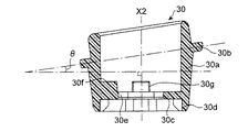
図5A、図6に示される照明リングボディ30は、合成樹脂などの透明又は半透明な素材で形成される。照明リングボディ30は、中空の円筒形のボディ部30aと、そのまわりを取り囲む照明リング30bで構成される。照明リング30bは、照明リングボディ30の外表面から突出する環状の構造体で有り、環状のフランジを形成する。照明リング30bは、X2軸と直角な平面に対し所定の角度θ、例えば6度から10度の範囲内のある角度、好ましくは8度、で傾いている。グリップ部分2の一部として存在する円筒形のボディ部30aの両端は、開口されており、内側には内部プレート30cを有する。内部プレート30cより下側の円筒の壁はスカート壁30dを形成する。内部プレート30cの中央には、疑似円形の開口30e(図5B)が形成され、図8において最もよく示されるように、開口30eには横断面が疑似円形を有する首部26が圧入される。内部プレート30cより上側の円筒状のボディ部30aは受口30iが形成され、後で説明する様に、ステムジョイント42の下側シリンダ部分42bであって、ボトムゴムカバー46が嵌められたものが圧入される。この実施形態においては、照明リングボディ30は円筒形のボディ部30aと照明リング30bを有しているが、形状は円筒形に限らず、電動歯ブラシ1のグリップ部分2のデザインや形状に応じて、他の形状であっても良い。
The
図5Bに示すように、内部プレート30cの上側表面には、3つのブロック30f、30g、30hが形成され、それらは内部プレート30cと円筒形のボディ部30aの内壁との間の角に位置する。
照明リングボディ30の外側には、図5Aに示すように、1対の突出部30pが設けられている。
As shown in FIG. 5B, on the upper surface of the
On the outside of the
回路基板50が取り付けられたシャーシ20は、ボディカバー10の下側の開口から挿入され、図4に示すように、シャーシ20の上側先端がボディカバー10の上側の開口端からやや下がった位置で係止するように、ボディカバー10内に保持される。
The
図7、図8に示す様に、照明リングボディ30はシャーシ20の肩部24a、24bに設置され、シャーシ20の首部26が開口30eに密着して嵌まるように挿入される。この状態において、内部プレート30cの底面は、シャーシ20の肩部24a、24bと当接し、スカート壁30dは、傾斜面28b、28c、29b、29cの全体又は少なくとも一部を取り囲むような位置に配置される。また、照明リング30bより下側の照明リングボディ30の外表面は、ボディカバー10の上端の開口に挿入され、照明リングボディ30の外側に設けた突出部30pがボディカバー10の内側表面に形成した補完凹部(図示せず)と係合する。これにより、ボディカバー10と照明リングボディ30とが抜け落ちしないように結合される。
As shown in FIGS. 7 and 8, the
図9に示すように、LED、例えばLED56a、56bから放射された光線は傾斜面28b、28cで反射し、スカート壁30d方向に向かい、照明リングボディ30の中に光学的に伝達される。光成分のいくらかは照明リング30bに導かれ、電動歯ブラシの表面に露出された照明リング30bの外周の環状面から放出される。
As shown in FIG. 9, light rays emitted from LEDs, for example,
図7に示すように、照明リングボディ30の外側の大部分は、ボディカバー10およびトップカバー12で覆われる。ボディカバー10およびトップカバー12は、同じ又は異なった材料で形成されても良いが、いずれにしても両者は、不透明な材料である。この実施形態においては、照明リング30bの外周面だけが電動歯ブラシ1の外側から直接見ることができる。
As shown in FIG. 7, most of the outside of the
照明リング30bの外周面を除く、照明リングボディ30の外周面は、反射膜材料で被覆しても良い。この様にする事により、スカート壁30dの内側の面を介して照明リングボディ30に入射した光線は、反射膜でほとんど漏れることなく照明リングボディ30内に止める事ができ、照明リング30bの外周面から放出することができる。従って、照明リング30bから電動歯ブラシ1の外部に向けて強い光線を出力することができる。
The outer peripheral surface of the
照明リング30bが、電動歯ブラシ1のグリップ部分2の上側に一周、すなわち360度全域から見える位置に設けられているので、電動歯ブラシ1をどのような角度で持ったとしても、照明リング30bから発光される照明を見ることができる。なお、上記の実施形態では、照明リング30bは、環状の連続したリング構造であるが、他の実施形態として、照明リング30bは、間欠したセグメントがリング状に並べられた間欠リング構造であっても良い。照明リング30bの発光は、次に説明するような種々の状況や種々の動作モードにおいて行うことができる。
Since the
1番目の状況として、電動歯ブラシ1のブラシの毛先が水平面に対し、上側または下側に約45度の角度で向けられたとき、すなわち毛先が上の歯または下の歯の前側または裏側から歯周ポケットに向けられたときに、発光が行われる。 In the first situation, when the bristle tips of the electric toothbrush 1 are oriented at an angle of about 45 degrees upward or downward with respect to the horizontal plane, that is, the bristle tips are at the front side or the back side of the upper tooth or the lower tooth. The light is emitted when directed from the to the periodontal pocket.
2番目の状況として、電動歯ブラシ1のブラシの毛先が水平面に対し、直角方向に向けられたとき、すなわち毛先が大臼歯、または小臼歯の咬合面に向けられたときに、発光が行われる。 As a second situation, when the bristle tips of the electric toothbrush 1 are oriented in a direction perpendicular to the horizontal plane, that is, when the bristle tips are oriented toward the occlusal surface of a molar or premolar, light emission occurs. Be seen.
3番目の状況として、電動歯ブラシ1のブラシの毛先が水平面の方向に向けられたとき、すなわち毛先が歯の前側または裏側から歯に垂直に向けられたときに、発光が行われる。 As a third situation, light emission occurs when the bristle tips of the electric toothbrush 1 are oriented in the direction of the horizontal plane, that is, when the bristle tips are oriented vertically from the front side or the back side of the teeth to the teeth.
上記の状況はいずれも、米国特許公開公報第No.2012/0251975号明細書、(日本特許公開公報2011−156204に対応する)または日本特許公報2009−291316において開示された加速度センサーによって検出することができる。これらの特許文献を引用することにより、本願明細書の内容に盛り込まれるものとする。 In each of the above situations, US Pat. It can be detected by the acceleration sensor disclosed in the specification of 2012/0251975 (corresponding to Japanese Patent Publication No. 2011-156204) or Japanese Patent Publication No. 2009-291316. The contents of the specification of the present application are incorporated by reference to these patent documents.
動作モードは状況毎に変更することができる。例えば、第1の動作モードは、オン・オフモードとし、毛先角度が上述した所定の目標角度になっていることを検出したときにLEDをオンにするようにしてもよい。 The operation mode can be changed for each situation. For example, the first operation mode may be an on / off mode, and the LED may be turned on when it is detected that the bristle tip angle has reached the above-described predetermined target angle.
第2の動作モードは、照明可変モードとし、毛先角度が上述した所定の目標角度に近づくに従ってLEDの明るさ(すなわち照度)を変えるようにしても良い。 The second operation mode may be an illumination variable mode, and the brightness (that is, illuminance) of the LED may be changed as the tip angle approaches the above-described predetermined target angle.
第3の動作モードは、点滅モードとし、毛先角度が上述した所定の目標角度に近づくに従ってLEDの点滅の周波数を上げるようにしても良い。 The third operation mode may be a blinking mode, and the blinking frequency of the LED may be increased as the bristle tip angle approaches the predetermined target angle described above.
また、ある実施形態では、発光を行うのは、上で説明した3つの状況のうちの1つだけについて行うようにしても良い。この場合の動作モードは、上述した3つ動作モードの内の一つを用いれば良い。 Also, in some embodiments, the light emission may occur in only one of the three situations described above. As the operation mode in this case, one of the three operation modes described above may be used.
図2において、ステム連結部材40は、ステムジョイント42と、ステムパッキング44と、ボトムゴムカバー46を含む。
In FIG. 2, the
図10と図11において、ステムジョイント42は、上側シリンダ部分42aと、下側シリンダ部分42bを有する。上側シリンダ部分42aの軸は、X4軸と一致し、下側シリンダ部分42bの軸は、X2軸と一致する。
10 and 11, the stem joint 42 has an
上側シリンダ部分42aの内側には雌のネジ溝42cが形成されている。上側シリンダ部分42aの上端面には、傾斜突出部42dとストッパー突出部42eが形成されている。傾斜突出部42dの一方の側は、傾斜面を有し、他方の側は、直立面を有する。ストッパー突出部42eの両側は直立面を有する。傾斜突出部42dの直立面とストッパー突出部42eの直立面との間に、すなわちネジ溝42cの近傍に、第2係合部である係合凹部42fが形成されている。第1係合部85は後で説明する。
A female thread groove 42c is formed inside the
図12において、下側シリンダ部分42bが、リング状凹部42gと、3つの脚部42h、42i、42jを有する。脚部42i、42jは、対称性を有し、両者と対向する位置に脚部42hが配置されている。脚部42h、42iの間にインデント42kが形成される。脚部42h、42jの間にインデント42lが形成される。脚部42i、42jの間にインデント42mが形成される。
In FIG. 12, the
図2,図7に示す様に、ゴム製の又は同様な材料で形成されたステムパッキング44は、リング状凹部42gに挿入される。ボトムゴムカバー46は下側シリンダ42bに被せられ、脚部42h、42i、42jを個別的にカバーする(図10−12参照)。従って、ボトムゴムカバー46の外側にもインデント42k、42l、42mが現れる。
As shown in FIGS. 2 and 7, a stem packing 44 made of rubber or a similar material is inserted into the ring-shaped recess 42g. The
図2,図7を参照し、次に、下側シリンダ部分42bと照明リングボディ30との連結について説明する。
Next, with reference to FIGS. 2 and 7, the connection between the
ボトムゴムカバー46が被せられた下側シリンダ部分42bは、照明リングボディ30の円筒形のボディ部30aの受口30iに圧入され、ボトムゴムカバー46の外側に現れるインデント42k、42l、42mが、3つのブロック30g、30h、30fと係合する。従って、下側シリンダ部分42bは、円筒形のボディ部30aに対し、自由回転することができず、強固に保持される。
The
図7に示すように、ステム80は、長手の空洞86を有し、その中に振動シャフト70と直流モータ60により構成される振動発生機が収納される。振動シャフト70は、合成樹脂で構成される延長シャフト72と、金属で構成される偏心軸73を含む。延長シャフト72は、例えばポリプラスチックス株式会社によって製造されたPOM(ポリオキシメチレンと呼ばれる材料)によって一体形成される。振動シャフト70の延長シャフト72は、下端近傍に設けられたカラー部分74、弾力性を有するシャフト部分75、および連結部分76を含み、それらは合成樹脂、例えばPOMによって一体形成される。延長シャフト72の下端面には、直流モータ60のシャフトと連結される凹部が形成されている。直流モータ60は、その下側面から2本のワイヤーが延在し、コネクタ58を介して回路基板50と電気的接続が成される。振動シャフト70と直流モータ60は、長手の空洞86内に納められ、モータサポート62により固定される。
As shown in FIG. 7, the
振動シャフト70の偏心軸73は、偏心部分77とシャフト部分78を含む。偏心部分77の下端は、成型により連結部分76と固着され、偏心部分77の上端はシャフト部分78が設けられている。
The
振動シャフト70が直流モータ60によって回転されると、偏心部分77は高周波振動を発生し、その振動は、ステム構造部80およびブラシ90に伝えられる。弾力性のあるシャフト部分75は、偏心部分77の高周波振動を受け付ける柔軟性を有する。
When the vibrating
ステム80もPOMによって形成される。穴部87は、長手中空部86の先端に形成される。穴部87にはシャフト部分78が回転可能に挿入される。長手中空部86内には振動シャフト70および直流モータ60が収納される。振動シャフト70は、長手中空部86内において自由に回転する。穴部87は、シャフト部分78を自由に回転保持するためのベアリングとして機能する。振動シャフト70は、高周波振動を受けつつ長手中空部86の内部で自由に回転する。
The
穴部87がベアリングとして機能するので、シャフト部分78を回転自在に保持するためのベアリング部材を別途設ける必要はない。
Since the
図13において、ステム80の下端部分の詳細が示されている。ステム80は、カラー部分82を有し、カラー部分82より下側には雄のネジ溝84が形成されている。第1係合部である突出部85がネジ溝84の近傍、例えばカラー部分82の真下、すなわちネジ溝84の終端近傍に形成されている。
In FIG. 13, details of the lower end portion of the
X4軸を中心にステム80を回転することによりステム80の雄のネジ溝84がステムジョイント42の雌のネジ溝42cに螺合し、ステム80とステムジョイント42は強固に接続される。ステム80が、所定回数、回転すると、第1係合部である突出部85が傾斜突出部42dの傾斜面の上を滑り、図14に示す様に、第2係合部である係合凹部42fの中に保持される。この状態においては、ステム80はいずれの方向にも回転する事ができず、グリップ部2に対しブラシ90が正しい方向に向くように、所定の回転した位置に保持される。第1係合部である突出部85と第2係合部である係合凹部42fは、逆であってもよいし、他の係合する構造であってもよい。また、ネジ溝84,42cの雄雌の関係は、逆であってもよい。
By rotating the
図2,図7に示す様に、トップゴムカバー14がステム80の上側から被せられ、トップゴムカバー14の底面がカラー部分82の上部に当接する。そして、トップカバー12がステム80の上に設置され、トップカバー12の底面が照明リング30bの上部に当接する。
As shown in FIGS. 2 and 7, the
好ましい実施形態によると、適当な接着剤が、長手のボディカバー10と照明リングボディ30との間、照明リングボディ30とステムジョイント42との間、およびステムジョイント42とステム80との間の内の少なくとも一箇所において使われる。
According to a preferred embodiment, a suitable adhesive is applied between the
上記の実施形態においては、傾斜面28b、28c、29b、29cをシャーシ(20)の一部に形成したが、他の部分、例えば照明リングボディ30の内部プレート30cの下側面に形成してもよい。
In the above embodiment, the
他の実施形態では、傾斜面を省略し、LED56a、56b、56c、56dからの光を直接照明リングボディ30に入射する様にしても良い。
In another embodiment, the inclined surface may be omitted, and the light from the
また、照明リング30bは、グリップ部分2とブラシ部分4との間、詳しくはグリップ部分2と中間部分との間に設けたが、グリップ部分2の中に設けても良いし、中間部分の中に設けても良い。
Further, although the
電動歯ブラシは口内のヘルスケアに利用することができる。 Electric toothbrushes can be used for oral health care.
1...電動歯ブラシ、2...グリップ部分、4...ブラシ部分、10...ボディカバー、12...トップカバー、14...トップゴムカバー、16...バッテリーホルダー、20...シャーシ、22a、22b...指、24a、24b...肩部、26...首部、26a、26b...凹部、28、29...スルーホール、28b、28c、29b、29c...傾斜面、30...照明リングボディ、30a...中空の円筒形のボディ部、30b...照明リング、30c...内部プレート、30d...スカート壁、30e...開口、30f、30g、30h...ブロック、40...ステム連結部材、42...ステムジョイント、42c...雌のネジ溝、42d...傾斜突出部、42e...ストッパー突出部、42h、42i、42j...脚部、42k、42l、42m...インデント、44...ステムパッキング、46...ボトムゴムカバー、50...長手の回路基板、52...長手基盤、54...U字形プレート、56a、56b、56c、56d...LEDs、60...直流モータ、62...モータサポート、70...振動シャフト、80...ステム、90...替ブラシ 1 ... Electric toothbrush, 2 ... Grip part, 4 ... Brush part, 10 ... Body cover, 12 ... Top cover, 14 ... Top rubber cover, 16 ... Battery holder, 20 ... chassis, 22a, 22b ... fingers, 24a, 24b ... shoulders, 26 ... necks, 26a, 26b ... recesses, 28, 29 ... through holes, 28b, 28c, 29b , 29c ... Inclined surface, 30 ... Illumination ring body, 30a ... Hollow cylindrical body part, 30b ... Illumination ring, 30c ... Inner plate, 30d ... Skirt wall, 30e ... openings, 30f, 30g, 30h ... blocks, 40 ... stem connecting members, 42 ... stem joints, 42c ... female thread grooves, 42d ... inclined protrusions, 42e ... .Stopper protrusions, 42h, 42i, 42j ... legs, 42k, 42l, 42m ... indent, 44 ... stem packing 46 ... Bottom rubber cover, 50 ... Long circuit board, 52 ... Long board, 54 ... U-shaped plate, 56a, 56b, 56c, 56d ... LEDs, 60 ... DC motor , 62 ... motor support, 70 ... vibrating shaft, 80 ... stem, 90 ... replacement brush
Claims (11)
発光可能な照明リング(30b)を備えた照明リングボディ(30)、
光線を放出する発光素子(56a、56b、56c、56d)、
グリップ部分(2)内に設けた回路基板(50)であって、発光素子のオン・オフ制御を行う制御部を含む回路基板(50)
を含み、
前記照明リングボディ(30)は、透明な材料で形成された中空の円筒型のボディ部(30a)と、ボディ部(30a)の内部に設けられ、開口(30e)を有する内部プレート(30c)とを有し、前記照明リング(30b)は、ボディ部(30a)の外側にリング状に存在する、
電動歯ブラシ。 An electric toothbrush having a longitudinal grip portion (2) and a longitudinal brush portion (4), comprising:
An illumination ring body (30) having an illumination ring (30b) capable of emitting light,
Light emitting elements (56a, 56b, 56c, 56d) that emit light rays,
A circuit board (50) provided in the grip portion (2) including a control unit for performing on / off control of a light emitting element.
Only including,
The illumination ring body (30) is a hollow cylindrical body part (30a) made of a transparent material, and an inner plate (30c) provided inside the body part (30a) and having an opening (30e). And the illumination ring (30b) exists in a ring shape outside the body portion (30a).
electric toothbrush.
Priority Applications (6)
| Application Number | Priority Date | Filing Date | Title |
|---|---|---|---|
| JP2016051473A JP6679355B2 (en) | 2016-03-15 | 2016-03-15 | Electric toothbrush with lighting ring |
| PCT/US2017/022269 WO2017160811A1 (en) | 2016-03-15 | 2017-03-14 | Electric toothbrush with an illumination ring |
| CN201780017263.5A CN108778053B (en) | 2016-03-15 | 2017-03-14 | Electric toothbrush with lighting ring |
| US16/084,796 US10743650B2 (en) | 2016-03-15 | 2017-03-14 | Electric toothbrush with an illumination ring |
| EP17714338.5A EP3413750A1 (en) | 2016-03-15 | 2017-03-14 | Electric toothbrush with an illumination ring |
| US16/921,225 US11317711B2 (en) | 2016-03-15 | 2020-07-06 | Electric toothbrush with an illumination ring |
Applications Claiming Priority (1)
| Application Number | Priority Date | Filing Date | Title |
|---|---|---|---|
| JP2016051473A JP6679355B2 (en) | 2016-03-15 | 2016-03-15 | Electric toothbrush with lighting ring |
Publications (2)
| Publication Number | Publication Date |
|---|---|
| JP2017164214A JP2017164214A (en) | 2017-09-21 |
| JP6679355B2 true JP6679355B2 (en) | 2020-04-15 |
Family
ID=58448620
Family Applications (1)
| Application Number | Title | Priority Date | Filing Date |
|---|---|---|---|
| JP2016051473A Active JP6679355B2 (en) | 2016-03-15 | 2016-03-15 | Electric toothbrush with lighting ring |
Country Status (5)
| Country | Link |
|---|---|
| US (2) | US10743650B2 (en) |
| EP (1) | EP3413750A1 (en) |
| JP (1) | JP6679355B2 (en) |
| CN (1) | CN108778053B (en) |
| WO (1) | WO2017160811A1 (en) |
Families Citing this family (28)
| Publication number | Priority date | Publication date | Assignee | Title |
|---|---|---|---|---|
| US9889066B2 (en) | 2013-07-01 | 2018-02-13 | Good Fortune 5, Llc | Massaging device having a heat sink |
| GB2555418B (en) | 2016-10-26 | 2019-03-06 | Dyson Technology Ltd | Cleaning Appliance |
| GB2555417B (en) * | 2016-10-26 | 2020-01-22 | Dyson Technology Ltd | Cleaning Appliance |
| US10603150B2 (en) | 2017-12-12 | 2020-03-31 | Colgate-Palmolive Company | Oral care implement |
| US10603147B2 (en) | 2017-12-12 | 2020-03-31 | Colgate-Palmolive Company | Oral care implement |
| US10631964B2 (en) | 2017-12-12 | 2020-04-28 | Colgate-Palmolive Company | Oral care implement |
| US10709533B2 (en) | 2017-12-12 | 2020-07-14 | Colgate-Palmolive Company | Oral care implement and handle and refill head thereof |
| US10639133B2 (en) | 2017-12-12 | 2020-05-05 | Colgate-Palmolive Company | Oral care implement and handle and refill head thereof |
| USD960581S1 (en) | 2018-02-09 | 2022-08-16 | The Gillette Company Llc | Toothbrush head |
| USD912988S1 (en) | 2018-02-09 | 2021-03-16 | The Gillette Company Llc | Toothbrush handle |
| GB2575022B (en) | 2018-06-20 | 2020-09-30 | Dyson Technology Ltd | Dental treatment appliance |
| US11324307B2 (en) | 2018-08-02 | 2022-05-10 | Ranir, Llc | Pressure sensing system and method for an electric toothbrush |
| USD931617S1 (en) | 2018-09-03 | 2021-09-28 | The Gillette Company Llc | Toothbrush head |
| USD891784S1 (en) | 2018-12-18 | 2020-08-04 | Colgate-Palmolive Company | Electric toothbrush handle |
| USD901183S1 (en) | 2019-03-22 | 2020-11-10 | The Gillette Company Llc | Toothbrush |
| US11470954B2 (en) | 2019-12-19 | 2022-10-18 | Colgate-Palmolive Company | Oral care system |
| USD950956S1 (en) | 2019-12-19 | 2022-05-10 | Colgate-Palmolive Company | Oral care implement handle |
| USD967632S1 (en) | 2019-12-19 | 2022-10-25 | Colgate-Palmolive Company | Replacement head for a toothbrush |
| US11406480B2 (en) | 2019-12-19 | 2022-08-09 | Colgate-Palmolive Company | Oral care implement and refill head thereof |
| US11425995B2 (en) | 2019-12-19 | 2022-08-30 | Colgate-Palmolive Company | Powered oral care implement |
| US11484253B2 (en) | 2019-12-19 | 2022-11-01 | Colgate-Palmolive Company | Oral care system |
| USD950955S1 (en) | 2019-12-19 | 2022-05-10 | Colgate-Palmolive Company | Oral care implement |
| USD972302S1 (en) | 2020-03-13 | 2022-12-13 | Ranir, Llc | Toothbrush drive unit |
| USD1014095S1 (en) | 2020-07-02 | 2024-02-13 | The Gillette Company Llc. | Toothbrush |
| USD957135S1 (en) | 2020-07-02 | 2022-07-12 | The Gillette Company Llc | Toothbrush head |
| USD994341S1 (en) | 2020-11-06 | 2023-08-08 | The Gillette Company Llc | Toothbrush |
| USD960582S1 (en) | 2020-12-10 | 2022-08-16 | Colgate-Palmolive Company | Oral care refill head |
| EP4364693A1 (en) * | 2022-11-07 | 2024-05-08 | Koninklijke Philips N.V. | Assistance during usage of a personal care device |
Family Cites Families (14)
| Publication number | Priority date | Publication date | Assignee | Title |
|---|---|---|---|---|
| US7086111B2 (en) * | 2001-03-16 | 2006-08-08 | Braun Gmbh | Electric dental cleaning device |
| CN2569631Y (en) * | 2002-09-04 | 2003-09-03 | 哥第斯科技有限公司 | Toothbrush with light function |
| US8692930B2 (en) * | 2007-08-20 | 2014-04-08 | Matthew Rolston Photographer, Inc. | Mobile device with operation for modifying visual perception |
| JP5292913B2 (en) | 2008-05-09 | 2013-09-18 | オムロンヘルスケア株式会社 | electric toothbrush |
| JP2009291316A (en) | 2008-06-03 | 2009-12-17 | Omron Healthcare Co Ltd | Electric toothbrush |
| EP2189198B1 (en) * | 2008-11-20 | 2017-06-21 | Braun GmbH | Personal body care device |
| JP5365277B2 (en) * | 2009-03-17 | 2013-12-11 | オムロンヘルスケア株式会社 | electric toothbrush |
| ES2386508T3 (en) | 2009-03-20 | 2012-08-22 | Braun Gmbh | Electric toothbrush and procedure to make an electric toothbrush |
| CA2762817A1 (en) | 2009-05-20 | 2010-11-25 | Braun Gmbh | Personal body cleaning device |
| EP2253359A1 (en) * | 2009-05-20 | 2010-11-24 | Braun GmbH | Personal body cleaning device |
| JP5526825B2 (en) | 2010-02-02 | 2014-06-18 | オムロンヘルスケア株式会社 | Oral care device |
| CN202020561U (en) * | 2011-03-30 | 2011-11-02 | 深圳瑞圣特电子科技有限公司 | Electric toothbrush with electric quantity warning function |
| US9439740B2 (en) * | 2011-05-05 | 2016-09-13 | Braun Gmbh | Oral hygiene implement |
| WO2017129509A1 (en) * | 2016-01-26 | 2017-08-03 | Koninklijke Philips N.V. | Feedback device and method of providing same for users of oral care devices applying pressure during use |
-
2016
- 2016-03-15 JP JP2016051473A patent/JP6679355B2/en active Active
-
2017
- 2017-03-14 US US16/084,796 patent/US10743650B2/en active Active
- 2017-03-14 CN CN201780017263.5A patent/CN108778053B/en not_active Expired - Fee Related
- 2017-03-14 EP EP17714338.5A patent/EP3413750A1/en not_active Withdrawn
- 2017-03-14 WO PCT/US2017/022269 patent/WO2017160811A1/en active Application Filing
-
2020
- 2020-07-06 US US16/921,225 patent/US11317711B2/en active Active
Also Published As
| Publication number | Publication date |
|---|---|
| US20190082819A1 (en) | 2019-03-21 |
| US11317711B2 (en) | 2022-05-03 |
| JP2017164214A (en) | 2017-09-21 |
| US20200329858A1 (en) | 2020-10-22 |
| US10743650B2 (en) | 2020-08-18 |
| CN108778053B (en) | 2020-06-30 |
| WO2017160811A1 (en) | 2017-09-21 |
| CN108778053A (en) | 2018-11-09 |
| EP3413750A1 (en) | 2018-12-19 |
Similar Documents
| Publication | Publication Date | Title |
|---|---|---|
| JP6679355B2 (en) | Electric toothbrush with lighting ring | |
| JP6706103B2 (en) | Electric toothbrush with a firm connection between the grip and the brush | |
| CN208525096U (en) | Cleaning appliance | |
| JP5551191B2 (en) | Electric toothbrush and method for manufacturing electric toothbrush | |
| TWI435701B (en) | Oral care implement having multi-component handle | |
| RU2747618C1 (en) | Oral care device | |
| BR112016012521B1 (en) | TOOTHBRUSH WITH SHORT WAVE LIGHT VISIBLE EMITTER WITH AN ELECTRONIC SIGNAL BLOCKING CONTROL | |
| CN106943202B (en) | Electric tooth brush | |
| CN1842303A (en) | Electric toothbrush comprising an electrically powered element | |
| JP5139371B2 (en) | toothbrush | |
| RU2009139014A (en) | ELECTRICAL CARE DEVICE | |
| JP6711106B2 (en) | toothbrush | |
| WO2019116535A1 (en) | Cleaning brush | |
| CN210447254U (en) | Novel electric toothbrush structure | |
| US20240156246A1 (en) | Light guide member and indicator light assembly | |
| JP5661695B2 (en) | Lighting device | |
| CN117062551A (en) | Light guide member and indicator light fitting | |
| KR101507105B1 (en) | periscope of toothbrush type | |
| JP3011979U (en) | Toothbrush with pressure sensor |
Legal Events
| Date | Code | Title | Description |
|---|---|---|---|
| A621 | Written request for application examination |
Free format text: JAPANESE INTERMEDIATE CODE: A621 Effective date: 20190129 |
|
| A977 | Report on retrieval |
Free format text: JAPANESE INTERMEDIATE CODE: A971007 Effective date: 20191114 |
|
| A131 | Notification of reasons for refusal |
Free format text: JAPANESE INTERMEDIATE CODE: A131 Effective date: 20191119 |
|
| A521 | Request for written amendment filed |
Free format text: JAPANESE INTERMEDIATE CODE: A523 Effective date: 20200210 |
|
| TRDD | Decision of grant or rejection written | ||
| A01 | Written decision to grant a patent or to grant a registration (utility model) |
Free format text: JAPANESE INTERMEDIATE CODE: A01 Effective date: 20200310 |
|
| A61 | First payment of annual fees (during grant procedure) |
Free format text: JAPANESE INTERMEDIATE CODE: A61 Effective date: 20200318 |
|
| R150 | Certificate of patent or registration of utility model |
Ref document number: 6679355 Country of ref document: JP Free format text: JAPANESE INTERMEDIATE CODE: R150 |
|
| R250 | Receipt of annual fees |
Free format text: JAPANESE INTERMEDIATE CODE: R250 |
|
| R250 | Receipt of annual fees |
Free format text: JAPANESE INTERMEDIATE CODE: R250 |