JP6671920B2 - Power transmission device and control method thereof - Google Patents
Power transmission device and control method thereof Download PDFInfo
- Publication number
- JP6671920B2 JP6671920B2 JP2015209477A JP2015209477A JP6671920B2 JP 6671920 B2 JP6671920 B2 JP 6671920B2 JP 2015209477 A JP2015209477 A JP 2015209477A JP 2015209477 A JP2015209477 A JP 2015209477A JP 6671920 B2 JP6671920 B2 JP 6671920B2
- Authority
- JP
- Japan
- Prior art keywords
- power
- threshold
- antenna
- cpu
- transmission
- Prior art date
- Legal status (The legal status is an assumption and is not a legal conclusion. Google has not performed a legal analysis and makes no representation as to the accuracy of the status listed.)
- Active
Links
- 230000005540 biological transmission Effects 0.000 title claims description 208
- 238000000034 method Methods 0.000 title claims description 27
- 239000000126 substance Substances 0.000 claims description 53
- 230000008859 change Effects 0.000 claims description 50
- 238000001514 detection method Methods 0.000 claims description 40
- 238000004891 communication Methods 0.000 claims description 38
- 238000004590 computer program Methods 0.000 description 13
- 230000008569 process Effects 0.000 description 11
- 230000004044 response Effects 0.000 description 11
- 238000006243 chemical reaction Methods 0.000 description 7
- 238000010586 diagram Methods 0.000 description 6
- 230000006870 function Effects 0.000 description 5
- 238000009499 grossing Methods 0.000 description 3
- 230000008901 benefit Effects 0.000 description 2
- HBBGRARXTFLTSG-UHFFFAOYSA-N Lithium ion Chemical compound [Li+] HBBGRARXTFLTSG-UHFFFAOYSA-N 0.000 description 1
- 230000003321 amplification Effects 0.000 description 1
- 230000033228 biological regulation Effects 0.000 description 1
- 239000003990 capacitor Substances 0.000 description 1
- 230000008878 coupling Effects 0.000 description 1
- 238000010168 coupling process Methods 0.000 description 1
- 238000005859 coupling reaction Methods 0.000 description 1
- 239000013078 crystal Substances 0.000 description 1
- 230000005672 electromagnetic field Effects 0.000 description 1
- 230000005674 electromagnetic induction Effects 0.000 description 1
- 229910001416 lithium ion Inorganic materials 0.000 description 1
- 238000004519 manufacturing process Methods 0.000 description 1
- 238000003199 nucleic acid amplification method Methods 0.000 description 1
- 230000010355 oscillation Effects 0.000 description 1
- 238000009774 resonance method Methods 0.000 description 1
- 238000004904 shortening Methods 0.000 description 1
Images


Classifications
-
- H—ELECTRICITY
- H02—GENERATION; CONVERSION OR DISTRIBUTION OF ELECTRIC POWER
- H02J—CIRCUIT ARRANGEMENTS OR SYSTEMS FOR SUPPLYING OR DISTRIBUTING ELECTRIC POWER; SYSTEMS FOR STORING ELECTRIC ENERGY
- H02J50/00—Circuit arrangements or systems for wireless supply or distribution of electric power
- H02J50/10—Circuit arrangements or systems for wireless supply or distribution of electric power using inductive coupling
-
- H—ELECTRICITY
- H02—GENERATION; CONVERSION OR DISTRIBUTION OF ELECTRIC POWER
- H02J—CIRCUIT ARRANGEMENTS OR SYSTEMS FOR SUPPLYING OR DISTRIBUTING ELECTRIC POWER; SYSTEMS FOR STORING ELECTRIC ENERGY
- H02J50/00—Circuit arrangements or systems for wireless supply or distribution of electric power
- H02J50/60—Circuit arrangements or systems for wireless supply or distribution of electric power responsive to the presence of foreign objects, e.g. detection of living beings
-
- H—ELECTRICITY
- H02—GENERATION; CONVERSION OR DISTRIBUTION OF ELECTRIC POWER
- H02J—CIRCUIT ARRANGEMENTS OR SYSTEMS FOR SUPPLYING OR DISTRIBUTING ELECTRIC POWER; SYSTEMS FOR STORING ELECTRIC ENERGY
- H02J50/00—Circuit arrangements or systems for wireless supply or distribution of electric power
- H02J50/80—Circuit arrangements or systems for wireless supply or distribution of electric power involving the exchange of data, concerning supply or distribution of electric power, between transmitting devices and receiving devices
-
- H—ELECTRICITY
- H02—GENERATION; CONVERSION OR DISTRIBUTION OF ELECTRIC POWER
- H02J—CIRCUIT ARRANGEMENTS OR SYSTEMS FOR SUPPLYING OR DISTRIBUTING ELECTRIC POWER; SYSTEMS FOR STORING ELECTRIC ENERGY
- H02J7/00—Circuit arrangements for charging or depolarising batteries or for supplying loads from batteries
- H02J7/00032—Circuit arrangements for charging or depolarising batteries or for supplying loads from batteries characterised by data exchange
- H02J7/00045—Authentication, i.e. circuits for checking compatibility between one component, e.g. a battery or a battery charger, and another component, e.g. a power source
-
- H—ELECTRICITY
- H02—GENERATION; CONVERSION OR DISTRIBUTION OF ELECTRIC POWER
- H02J—CIRCUIT ARRANGEMENTS OR SYSTEMS FOR SUPPLYING OR DISTRIBUTING ELECTRIC POWER; SYSTEMS FOR STORING ELECTRIC ENERGY
- H02J7/00—Circuit arrangements for charging or depolarising batteries or for supplying loads from batteries
- H02J7/0042—Circuit arrangements for charging or depolarising batteries or for supplying loads from batteries characterised by the mechanical construction
Landscapes
- Engineering & Computer Science (AREA)
- Computer Networks & Wireless Communication (AREA)
- Power Engineering (AREA)
- Charge And Discharge Circuits For Batteries Or The Like (AREA)
- Near-Field Transmission Systems (AREA)
Description
本発明は、送電装置及びその制御方法に関する。 The present invention relates to a power transmission device and a control method thereof.
近年、電子機器に無線で電力を伝送できる電力伝送装置が知られている。 In recent years, a power transmission device capable of wirelessly transmitting power to an electronic device has been known.
無線電力伝送の場合、送電装置と受電装置の間に異物が存在すると、電力伝送効率が悪化することがある。また、異物によっては、無電電力により異物が発熱することがある。そこで、送電装置と受電装置(電子機器)との間の異物を、送電電力の大きさに関わらず一定の異物検出閾値で検出し、異物が検出された場合に、送電電力を下げて送電を継続する方法が提案されている(特許文献1参照)。 In the case of wireless power transmission, if there is a foreign substance between the power transmitting device and the power receiving device, the power transmission efficiency may deteriorate. Further, depending on the foreign matter, the foreign matter may generate heat due to wireless power. Therefore, a foreign object between the power transmitting device and the power receiving device (electronic device) is detected at a fixed foreign object detection threshold regardless of the magnitude of the transmitted power, and when the foreign object is detected, the transmitted power is lowered to reduce the power transmission. A continuation method has been proposed (see Patent Document 1).
特許文献1に記載された技術では、送電電力の大きさによらず一定の異物検出閾値を採用する結果として、異物を誤検出する可能性が高まる。異物に影響を与えない程度の低電力の送電時に、異物がないのに異物だと誤検出して必要のない送電制限を行ってしまうことがある。他方では、異物に影響を与えるような大電力の送電時に、異物があるのにその異物を検出できず、送電を継続してしまうことがある。 In the technique described in Patent Literature 1, as a result of adopting a fixed foreign object detection threshold regardless of the magnitude of transmission power, the possibility of erroneously detecting foreign objects increases. At the time of low-power transmission that does not affect the foreign matter, there is a case where an unnecessary detection is made as a foreign matter when there is no foreign matter, and unnecessary power transmission restriction is performed. On the other hand, when transmitting a large amount of electric power that affects a foreign object, the foreign object may not be detected although the foreign object is present, and the power transmission may be continued.
本発明は、送電装置と受電装置との間の異物を適切に検出して送電を制御する送電装置及びその制御方法を提示することを目的とする。 SUMMARY An advantage of some aspects of the invention is to provide a power transmission device that appropriately detects foreign matter between a power transmission device and a power reception device and controls power transmission, and a control method thereof.
本発明に係る電力伝送装置は、電子機器に無線で電力を伝送する電力伝送装置であって、前記電力を可変可能な送電手段と、前記電子機器以外の物体である異物が前記電力伝送装置近傍に存在するかどうかを検出する検出手段と、前記送電手段の出力電力の大きさに応じて前記検出手段により異物の有無を判定する閾値を変更する制御手段とを有し、前記異物検出閾値は、前記送電装置が送電できる電力を規定する情報と前記受電装置が受電できる電力を規定する情報に従い決定されることを特徴とする。 A power transmission device according to the present invention is a power transmission device that wirelessly transmits power to an electronic device, wherein a power transmission unit that can change the power, and a foreign object that is an object other than the electronic device is in the vicinity of the power transmission device. detecting means for detecting whether there on, the have a control means for changing the threshold value determining the presence or absence of a foreign object by the detection unit in accordance with the magnitude of the output power of the power transmission means, the foreign object detection threshold The power transmission device is determined in accordance with information defining power that can be transmitted by the power transmitting device and information defining power that can be received by the power receiving device .
本発明によれば、送電電力が低い場合と高い場合で異物検出の閾値を変更することで、異物の誤検出を減らし、送電時の安全性および送電時間の短縮が可能となる。 ADVANTAGE OF THE INVENTION According to this invention, the threshold value of a foreign substance detection is changed when transmission power is low and high, erroneous detection of a foreign substance is reduced, and safety at the time of power transmission and shortening of power transmission time are attained.
以下、図面を参照して、本発明の実施例を詳細に説明する。ただし、本発明は、以下に説明する実施例に限定されない。無線電力伝送の「無線」の代わりに「非接触」または「無接点」と呼ばれることもあるが、いずれも同じである。 Hereinafter, embodiments of the present invention will be described in detail with reference to the drawings. However, the present invention is not limited to the embodiments described below. The term "wireless" in wireless power transmission is sometimes called "contactless" or "contactless", but both are the same.
図1は、本発明に係る電力伝送システムの一実施例の利用状態を示すための斜視図である。本実施例の電力伝送システムは、送電装置100と、送電装置100から無線伝送さえた電力を受電する受電装置たる電子機器200とからなる。送電装置100上に受電装置たる電子機器200を載置して送電装置100から電子機器200に無線電力伝送する実施例を示しているが、自動車への無線電力伝送など、その他の無線電力伝送にも、本発明は適用可能である。送電装置100から電子機器200(受電装置)への無線電力伝送は、電磁誘導方式でも電磁界共鳴方式でもよい。
FIG. 1 is a perspective view showing a use state of an embodiment of a power transmission system according to the present invention. The power transmission system according to the present embodiment includes a
図2は、送電装置100と電子機器200の概略構成を示すためのブロック図である。図2に示すように、送電装置100は、アンテナ101から無線方式で電力を電子機器200に供給し、電子機器200は、送電装置100から無線で伝送される電力をアンテナ201により受信する。また、送電装置100と電子機器200は互いに、アンテナ101、201を介して制御信号及びデータを通信できる。電子機器200は、送電装置100から供給される電力を電池209に蓄電する。電子機器200は、電池209から供給される電力によって動作する携帯機器である。他に、車の様な移動体、デジタルカメラや携帯電話の様なモバイル機器、または、無線インタフェースを有するメモリもしくはバッテリ等が、電子機器200の代替として想定可能である。
FIG. 2 is a block diagram showing a schematic configuration of
本実施例では、送電装置100は、電子機器200が所定範囲内にあることを検知すると、電子機器200への無線電力伝送を開始する。所定範囲内は、例えば、電子機器200が送電装置100と通信できる範囲である。
In this embodiment, when detecting that the
図2を参照して、送電装置100構成と基本的な機能を説明する。アンテナ101は、電子機器200のアンテナ201と電磁結合して、電子機器200への無線電力伝送と、電子機器200との通信に使用される。アンテナ101はコイル状であり、電力及び通信信号を搬送する電磁波を外部に無線出力する。アンテナ101は、インダクタンス成分によりアンテナ201と結合する形態が望ましいが、キャパシタンスにより結合をしてもよい。
The configuration and basic functions of the
整合回路102は、アンテナ101と送電電力調整回路103との間でインピーダンスを整合し、アンテナ101の共振周波数を調整する回路である。整合回路102は、インダクタンス成分あるいはキャパシタンス成分をもつ受動素子を直並列に組み合わせた回路で構成され、その受動素子の組み合わせは、整合させたい状態に応じて適切に選定される。整合回路102の受動素子としてその値を変更可能な素子を使用するか、接続を切り替え可能とすることで、CPU110は、電子機器200の状態や位置に応じて整合回路102の特性を制御できる。
The
送電電力調整回路103は、発振部104の出力する交流信号を所定電力の交流信号(電力信号)に調整した上で整合回路102に供給する。送電電力調整回路103は例えば、スイッチングアンプにより構成される電力増幅部と、変換部105の出力直流電圧を送電電力調整回路103が必要とする直流電圧に調整する電力調整部からなる。電力調整部は例えば、変換部105から入力される電圧を通信部106またはCPU110からの制御信号に応じて所定の電圧に変更するDC・DCコンバータ等により構成される。
The transmission
発振部104は、所定周波数の交流信号を定常的に発生し、送電電力調整回路103に供給する回路であり、水晶振動子等により構成される。所定周波数は、無線電力伝送に適した周波数であって、50W程度までの電力信号の空間への放射を許可されている周波数帯であればよい。現在の法規制のしたでは、例えば、6.78MHzもしくは13.56MHzの様なHF帯に属するISMバンドの周波数帯、または、数100KHzの様なLF帯に属する周波数帯である。
The oscillating
変換部105は、電源コネクタ111から入力される商用交流電力から各部の必要とする直流電圧を生成して供給する交流/直流変換回路からなる。電源コネクタ111は、商用交流電源のコンセントに接続する。送電装置100の内部回路は、変換部105から供給される電力により動作する。
The
通信部106は、電子機器200(の通信部205)との間で、制御信号を含むデータを通信する手段であり、この通信のために、アンテナ101、整合回路102及び送電電力調整回路103を含む回路部に係る電圧信号の変復調を利用する。通信部106は、データ送信時、ROM108に保存されている所定のプロトコルに基づいて符号化された送信用データをCPU110から受信し、変調回路を介して送電電力調整回路103へ入力することで送信信号の変調を行う。通信部106が送電電力調整回路103に入力する信号に応じて、送電電力調整回路103が出力する信号に振幅変調がかかり、アンテナ101を介してデータを送信することができる。通信部106は、データ受信時、整合回路102の電圧あるいは電流の変化を検出し、フィルタ、コンパレータ、スイッチ等により構成される復調回路を介することで受信用のデータを復調する。
The
送電装置100と電子機器200間のデータ通信のプロトコルには種々のプロトコルを利用可能である。例えば、ISO14443、ISO15693、またはNFC(Near Field Communication)規格で規定されている近距離無線通信用プロトコルと互換性があるプロトコル等が利用できる。
Various protocols can be used as a protocol for data communication between the
RAM107は、書き換え可能なメモリであり、送電装置100の各部の動作を制御するコンピュータプログラム、各部の動作に関するパラメータ等のデータ、通信部106によって電子機器200から受信されたデータ等を記憶する。RAM107は、送電装置100が送電する対象を管理するための管理テーブルを記憶する。RAM107に記憶されている管理テーブルには、送電装置100が電子機器200から取得した機器情報に含まれる情報が登録される。
The
ROM108は、送電装置100の各部の動作を制御するコンピュータプログラム及び各部の動作に関するパラメータ等の情報と、送電装置100が電子機器200と通信を行うための通信方式に関するプログラムを記憶する。
The
通知部109は、送電装置100が電子機器200に送電が可能か否かをユーザに通知する。通知部109は、ディスプレイとブザー等、またはいずれかからなる。
The
CPU110は、送電装置100全体を制御するための手段であり、ROM108に記憶されるプログラムを読み込み、送電装置100の動作を制御する。具体的には、CPU110は、整合回路102の回路切り替えと可変受動素子の値調整を制御する。CPU110は、送電電力調整回路103を制御することで、電子機器200に送電する電力量を調整する。CPU110は、内蔵するAD変換機能を用いて、送電電力調整回路103が出力する送電電力を測定する。CPU110は、通信部106を介して電子機器200との間でコマンド/制御信号を送受信することができる。コマンドは、宛先を識別するための識別情報と、コマンドによって指示される動作を示すコマンドコード等を含む。
The
電子機器200の構成要素とその基本機能を説明する。アンテナ201は、アンテナ101から放射される電力を受信し、送電装置100との間で通信される信号をアンテナ101との間で仲介する。アンテナ201は、コイル状でインダクタンス成分によりアンテナ101と結合する形態が望ましいが、静電結合であってもよい。
The components of the
整合回路202は、アンテナ201と整流平滑回路203との間でインピーダンスの整合をとり、アンテナ201の共振周波数を調整する回路である。整合回路202は、整合回路102と同様に、インダクタンス成分あるいはキャパシタンス成分をもつ受動素子を直並列に組み合わせた回路で構成され、その受動素子の組み合わせは、整合させたい状態に応じて適切に選定される。整合回路202の受動素子としてその値を変更可能な素子を使用するか、接続が切り替え可能であり、CPU206は、電子機器200のモードや負荷状態に応じて、整合回路202の受動素子の値または切り替えを制御する。
The
整流平滑回路203は、整合回路202からの交流電力信号を直流に変換する回路であり、ダイオードとコンデンサにより構成される。
The rectifying /
レギュレータ204は、整流平滑回路203から出力される電圧信号を所定の電圧値に変換する回路である。レギュレータ204は、生成した電圧値の電圧を電子機器200の各部に電源として供給する。CPU206の制御下で、レギュレータ204は、電池209を充電する。
The
通信部205は、送電装置100の通信部106との間で種々のデータを通信する手段であり、この通信のために、アンテナ201及び整合回路202を含む回路部に係る電圧信号の変復調を利用する。通信部205は、データ受信時、整合回路202の電圧または電流の変化を検出し、受信データを復調する。通信部205は、受信データをCPU206に供給し、CPU206は、ROM208に記憶される所定のプロトコルに基づいてデータを復号する。データ送信時、CPU206は、ROM208に記憶される所定プロトコルに基づいて符号化された送信データを通信部205に供給し、通信部205は、CPU206からの送信データを変調する。このように変調された送信データは、整合回路202及びアンテナ201を介して送電装置100に転送され、アンテナ101及び整合回路102を介して通信部106に入力する。通信部205が有する変調回路はスイッチと抵抗により構成され、送信データに応じて負荷を変動させることにより負荷変調がかかり、アンテナ201を介して送電装置100にデータが送信される。
The
CPU206は、電子機器200全体を制御するための手段であり、ROM208に記憶されるプログラムを読み込み、電子機器200の動作を制御する。具体的には、CPU206は、整合回路202の回路切り替えと可変受動素子の値調整を制御する。CPU206は、レギュレータ204を制御することで、電池209の充電を制御する。CPU110は、内蔵するAD変換機能を用いて、電池209の電力残量を検出し、検出した電池残量に応じてトリクル充電制御、高速充電制御、定電圧制御及び定電流制御等を切り替えながら充電を制御してもよい。
The
CPU206は、通信部205を介して送電装置100との間でコマンド/制御信号を送受信することができる。ここでのコマンドは、宛先を識別するための識別情報と、コマンドによって指示される動作への応答結果等を含む応答信号を含む。CPU206は、電池209の電池残量に応じて、通信部205を用いて送電電力の変更を送電装置100に要求してもよい。
The
RAM207は、書き換え可能なメモリであり、電子機器200の各部の動作を制御するコンピュータプログラム、各部の動作に関するパラメータ等のデータ、送電装置100から送信されたデータ等を記憶する。ROM208は、電子機器200の各部の動作を制御するコンピュータプログラム及び各部の動作に関するパラメータ等の情報を記憶する。ROM208には、電子機器200の機器情報、受電能力情報及び表示データ等が格納される。電子機器200の機器情報は、電子機器200の識別ID、製造者名、機器名、製造年月日、電子機器200に対応する通信方式、電子機器200が送電装置100から無線伝送される電力を受信可能か否かを示す情報等を含む。
The
電池209は、電子機器200に着脱可能な、充電可能な二次バッテリであり、例えばリチウムイオン電池等である。電池209は、電子機器200の各部に対して電源電力を供給する。
The
図3は、送電装置100の送電動作を説明するためのフローチャートである。CPU110がROM108に記憶されているコンピュータプログラムを実行することにより、図3に示す処理を実現する。CPU110は、図3に示すフローチャートで表現される処理を一定時間間隔で繰り返し実行する。
FIG. 3 is a flowchart for describing the power transmission operation of
ステップS301において、CPU110は、通信部106を介して、電子機器200に認証要求を送信し、ステップS302に進む。CPU110は、予め決められた通信プロトコルを用いて、通信部106を制御することで電子機器200へ認証用のコマンドを送信する。
In step S301, the
ステップS302において、CPU110は、電子機器200から認証応答を受信したかどうかを判定する。電子機器200は、送電装置100からの認証要求に対し、認証に成功した場合に認証応答信号を送電装置100に返信する。通信部106は、電子機器200からの認証応答信号をCPU110に供給する。電子機器200からの認証応答信号は、電子機器200の機器情報及びパワークラス情報等を含む。機器情報は、電子機器200のID、機能及び仕様等からなり、送電可能機器かどうかを示す情報も含む。
In step S302,
パワークラス情報は、ローパワークラス、ミドルパワークラスまたはハイパワークラスなど、送電装置100が送電可能な最大電力および電子機器200が受電可能な最大電力を示す情報である。例えば、ローパワークラスは、送電可能な最大電力2W、受電可能な最大電力1Wを規定し、ハイパワークラスは、送電可能な最大電力15W、受電可能な最大電力6Wを規定する。
The power class information is information indicating the maximum power that the
電子機器200から応答がない場合(ステップS302でNo)、CPU110は認証応答を受信していないと判定し、ステップS301に戻る。電子機器200から認証応答があった場合(ステップS302でYes)、CPU110は、ステップS303に進む。
If there is no response from electronic device 200 (No in step S302),
ステップS303において、CPU110は、電子機器200からの送電要求を受信したかどうかを判定する。CPU110は、電子機器200から送電要求を受信した場合、ステップS304に進み、送電要求を受信しない場合、図3に示すフローチャートを終了する。
In step S303,
ステップS304において、CPU110は、送電装置100の持つパワークラス情報および電子機器200から認証応答として受信したパワークラス情報に基づき、送電装置100が電子機器200に送電する送電電力を決定する。例えば、送電装置100と電子機器200がともにハイパワークラス対応である場合、送電装置100はハイパワークラスで電子機器200に送電可能であり、送電電力は最大15Wとなる。送電装置100がハイパワークラス対応で、電子機器200がローパワークラス対応である場合、送電装置100はローパワークラスで電子機器200に送電可能であり、送電電力は最大2Wとなる。CPU110は、ステップS304からステップS305に進む。
In step S304,
ステップS305において、CPU110は、送電装置100から電子機器200への送電を開始する。CPU110は、送電電力調整回路103を制御して、送電出力をステップS304で決定した送電電力まで徐々に上げる。CPU110は、ステップS305からステップS306に進む。
In step S305,
ステップS306において、CPU110は、電子機器200以外の異物を検出する異物検出処理を行い、ステップS307に進む。異物検出処理の詳細な内容は、後述する。CPU110は、異物検出処理(ステップS307)の検出結果に従い、異物が検出された場合にはステップS308に進み、異物が検出されない場合には図3に示すフローチャートを終了する。
In step S306,
ステップS308において、CPU110は、送電装置100から電子機器200への送電を制限する処理を実行する。CPU110は、この送電制限処理では、送電電力調整回路103を制御して、送電出力を電子機器200と通信を行うのに十分な電力に制限する。CPU110は、送電電力を制限した後、図3に示すフローチャートを終了する。
In step S308,
ステップS304では、CPU110は送電装置100のパワークラス情報と電子機器200のパワークラス情報に基づき、送電電力を決定したが、送電装置100が一方的に送電電力を決定してもよい。また、CPU110は、電子機器200から受信したパワークラス情報または受電可能電力情報に基づいて送電電力を決定してもよい。
In step S304, the
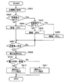
図4は、異物検出処理(S306)の詳細を説明するためのフローチャートである。ROM108には、図4に示す処理を実現するコンピュータプログラムが格納されており、CPU110は、このコンピュータプログラムをROM108から読み出し実行することで、図4に示す処理を実現する。図4に示すフローチャートでは、電力効率閾値により異物の有無を判定する。すなわち、異物の有無を判定するための異物検出閾値として電力効率閾値を採用する。
FIG. 4 is a flowchart illustrating the details of the foreign object detection process (S306). The
ステップS401において、CPU110は、送電装置100の送電電力を取得する。この送電電力は、ステップS304で決定した送電電力に基づき、送電装置100から電子機器200に向けて出力されている電力である。CPU110は、送電電力を取得すると、ステップS402に進む。
In step S401, the
ステップS402において、CPU110は、ステップS401で取得した送電電力が1W以上か否かを判定する。ステップS401で取得した送電電力が1W以上である場合(ステップS402でYes)、CPU110は、ステップS403に進む。ステップS401で取得した送電電力が1W未満である場合(ステップS402でNo)、CPU110は、ステップS404に進む。
In step S402, the
ステップS403において、CPU110は、ステップS401で取得した送電電力が6W以上か否かを判定する。ステップS401で取得した送電電力が6W以上である場合(ステップS403でYes)、CPU110は、ステップS406に進む。ステップS401で取得した送電電力が6W未満である場合(ステップS403でNo)、CPU110は、ステップS405に進む。
In step S403,
ステップS404において、CPU110は、異物検出閾値としての電力効率閾値を35%に設定し、ステップS407に進む。ステップS405において、CPU110は、異物検出閾値としての電力効率閾値を40%に設定し、ステップS407に進む。ステップS406において、CPU110は、異物検出閾値としての電力効率閾値を45%に設定し、ステップS407に進む。例えば、送電電力が0.5Wである場合、電力効率閾値は35%となる。送電電力が3Wである場合、電力効率閾値は40%となる。送電電力が10Wである場合、電力効率閾値は45%となる。このように送電電力が大きくなるほど、電力効率閾値は高く設定される。
In step S404, the
ステップS407において、CPU110は、通信部106を介して電子機器200から、電子機器200における受電電力情報を受信したか否かを判定する。電子機器200は、適時のタイミングでまたは送電装置100からの要求に基づき、電子機器200において受電した電力を受電電力情報として送電装置100に送信する。
In step S407,
CPU110は、電子機器200の受電電力情報を受信した場合(ステップS407でYes)、ステップS408に進む。電子機器200の受電電力情報を受信しない場合(ステップS407でNo)、CPU110は、ステップS407に戻り、電子機器200からの受電電力情報の受信を待つ。
When receiving the received power information of the electronic device 200 (Yes in step S407), the
ステップS408において、CPU110は、ステップS401で取得した送電電力とステップS407で取得した受電電力情報が示す受電電力の比(電力効率)を計算し、ステップS409に進む。例えば、送電電力が0.5W、電子機器200の受電電力が0.2Wである場合、電力効率は40%となる。送電電力が3W、電子機器200の受電電力が1.5Wである場合、電力効率は50%となる。
In step S408, the
ステップS409において、CPU110は、ステップS408で求めた電力効率を、ステップS404、S405またはS406で決定された電力効率閾値と比較する。ステップS408で求めた電力効率がステップS404,S405またはS406で決定された電力効率閾値より小さい場合(ステップS409でYes)、CPU110は、ステップS410に進む。ステップS408で求めた電力効率がステップS404,S405またはS406で決定された電力効率閾値以上の場合(ステップS409でNo)、CPU110は、ステップS411に進む。
In step S409, the
ステップS410において、CPU110は、異物ありと判定し、異物ありを示すフラグを設定する。ステップS411において、CPU110は、異物なしと判定し、異物なしを示すフラグを設定する。すなわち、CPU110は、異物がある場合、異物フラグを立て(異物フラグ=1)、異物が無い場合、異物フラグを下ろす(異物フラグ=0)。
In step S410,
例えば、送電電力が0.5W、受電電力が0.2Wである場合、電力効率(40%)>電力効率の閾値(35%)となり、CPU110は、異物なしと判定する。送電電力が0.5W、受電電力が0.1Wである場合、電力効率(20%)<電力効率閾値(35%)となり、CPU110は、異物ありと判定する。送電電力が3W、受電電力が1.5Wである場合、電力効率(50%)>電力効率閾値(40%)となり、CPU110は、異物なしと判定する。送電電力が3W、受電電力が1Wである場合、電力効率(33%)<電力効率閾値(40%)となり、CPU110は、異物ありと判定する。送電電力が10W、受電電力が5Wである場合、電力効率(50%)>電力効率閾値(45%)となり、CPU110は、異物なしと判定する。送電電力が10W、受電電力が4Wである場合、電力効率(40%)<電力効率閾値(45%)となり、CPU110は、異物ありと判定する。
For example, when the transmission power is 0.5 W and the reception power is 0.2 W, the power efficiency (40%)> the threshold value of the power efficiency (35%), and the
図4から明らかなように、本実施例では、送電電力が低いほど異物判定の電力効率閾値を低く設定し、送電電力が高いほど異物判定の電力効率閾値を高く設定する。これにより、送電電力が少ない場合に異物ありと判定される機会が減り、この結果、電子機器200への送電をより短時間で完了させることが可能になる。他方、送電電力が高い場合には、異物を積極的に判定することになり、送電時の安全性が高まる。
As is clear from FIG. 4, in the present embodiment, the power efficiency threshold for foreign matter determination is set lower as the transmission power is lower, and the power efficiency threshold for foreign matter determination is set higher as the transmission power is higher. This reduces the chance of determining that there is a foreign substance when the transmitted power is small, and as a result, it is possible to complete the power transmission to the
図4に示すフローでは、送電電力に応じて電力効率閾値を決定したが、送電装置100および電子機器200のパワークラスに応じて電力効率の閾値を決定してもよい。また、ステップS408で決定された電力効率を、送電電力に応じて決定した補正係数で補正し、その補正結果を一定の電力効率閾値と比較することでも、同様の結果を得ることができる。その補正係数は、ステップS402〜S406と同様の処理または区分で決定すれば良い。
In the flow illustrated in FIG. 4, the power efficiency threshold is determined according to the transmission power. However, the power efficiency threshold may be determined according to the power classes of the
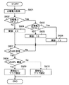
図5は、異物検出処理(S306)の別の動作を説明するためのフローチャートである。ここでは、アンテナ101に流れるアンテナ電流の変化量により異物の有無を判定する。ROM108には、図5に示すフローチャートの処理を実現するコンピュータプログラムが格納されており、CPU110は、このコンピュータプログラムをROM108から読み出し実行することで、図5に示す処理を実現する。
FIG. 5 is a flowchart for explaining another operation of the foreign object detection process (S306). Here, the presence or absence of a foreign object is determined based on the amount of change in the antenna current flowing through the
ステップS501において、CPU110は、送電装置100の送電電力を取得する。この送電電力は、ステップS304で決定した送電電力に基づき、送電装置100から電子機器200に向けて出力されている電力である。CPU110は、送電電力を取得すると、ステップS502に進む。
In step S501,
ステップS502において、CPU110は、ステップS501で取得した送電電力が1W以上か否かを判定する。ステップS501で取得した送電電力が1W以上である場合(ステップS502でYes)、CPU110は、ステップS503に進む。ステップS501で取得した送電電力が1W未満である場合(ステップS502でNo)、CPU110は、ステップS504に進む。
In step S502, the
ステップS503において、CPU110は、ステップS501で取得した送電電力が6W以上か否かを判定する。ステップS501で取得した送電電力が6W以上である場合(ステップS503でYes)、CPU110は、ステップS506に進む。ステップS501で取得した送電電力が6W未満である場合(ステップS503でNo)、CPU110は、ステップS505に進む。
In step S503,
ステップS504において、CPU110は、アンテナ電流変化量閾値を20mAに設定し、ステップS507に進む。ステップS505において、CPU110は、アンテナ電流変化量閾値を15mAに設定し、ステップS507に進む。ステップS506において、CPU110は、アンテナ電流変化量閾値を10mAに設定し、ステップS507に進む。
In step S504, the
例えば、送電電力が0.5Wである場合、アンテナ電流変化量閾値は20mAとする。送電電力が3Wである場合、アンテナ電流変化量閾値を15mAとする。送電電力が10Wである場合、アンテナ電流変化量閾値を10mAとする。このように、送電電力が大きくなるほど、アンテナ101のアンテナ電流変化量閾値を低く設定する。
For example, when the transmitted power is 0.5 W, the antenna current change amount threshold is set to 20 mA. When the transmission power is 3 W, the threshold value of the antenna current change amount is set to 15 mA. When the transmission power is 10 W, the antenna current change amount threshold is set to 10 mA. As described above, as the transmission power increases, the threshold value of the amount of change in the antenna current of the
ステップS504、S505、S506において、アンテナ101のアンテナ電流変化量は、異物が存在しない場合にアンテナ101に流れる電流を基準電流値として、その基準電流値からの電流変化量を示す。
In steps S504, S505, and S506, the amount of change in the antenna current of the
ステップS507において、CPU110は、アンテナ101に流れるアンテナ電流の大きさを取得するのを待機する。CPU110は、アンテナ101に流れるアンテナ電流の大きさを取得した場合(ステップS507でYes)、ステップS508に進む。
In step S507, the
ステップS508において、CPU110は、アンテナ電流の基準電流量(異物が存在しない場合にアンテナ101に流れる電流の大きさ)に対して、ステップS507で取得した電流値がどれほど変化したかを算出する。例えば、送電電力が0.5Wで、異物が存在しない場合にアンテナ101に流れる電流の大きさ(基準電流量)が100mAであったとき、ステップS507で取得したアンテナ電流量が130mAであれば、アンテナ電流変化量は30mAとなる。送電電力が0.5Wで、ステップS507で取得したアンテナ電流量が85mAであるとき、アンテナ電流変化量は15mAとなる。送電電力が3Wで、異物が存在しない場合の基準電流量が150mAとしたとき、ステップS507で取得したアンテナ電流量が170mAであると、アンテナ電流変化量は20mAとなる。送電電力が3Wで、ステップS507で取得したアンテナ電流量が140mAであるとき、アンテナ電流変化量は10mAとなる。CPU110は、アンテナ電流変化量を算出すると、ステップS509に進む。
In step S508, the
ステップS509において、CPU110は、ステップS508で算出したアンテナ電流変化量を、ステップS504、S505またはS506で決定されたアンテナ電流変化量閾値と比較する。
In step S509, the
ステップS509において、CPU110は、ステップS508で求めたアンテナ電流変化量を、ステップS504、S505またはS506で決定されたアンテナ電流変化量閾値と比較する。ステップS508で求めたアンテナ電流変化量がステップS504,S505またはS506で決定されたアンテナ電流変化量閾値を超える場合(ステップS509でYes)、CPU110は、ステップS510に進む。ステップS508で求めたアンテナ電流変化量がステップS504,S505またはS506で決定されたアンテナ電流変化量閾値以下の場合(ステップS509でNo)、CPU110は、ステップS511に進む。
In step S509, the
ステップS510において、CPU110は、異物ありと判定し、異物ありを示すフラグを設定する。ステップS511において、CPU110は、異物なしと判定し、異物なしを示すフラグを設定する。すなわち、CPU110は、異物がある場合、異物フラグを立て(異物フラグ=1)、異物が無い場合、異物フラグを下ろす(異物フラグ=0)。
In step S510,
例えば、送電電力が0.5W、アンテナ101のアンテナ電流変化量が30mAである場合、アンテナ電流変化量(30mA)>アンテナ電流変化量閾値(20mA)となり、CPU110は、異物ありと判定する。送電電力が0.5W、アンテナ101のアンテナ電流変化量が15mAである場合、アンテナ電流変化量(15mA)<アンテナ電流変化量閾値(20mA)となり、CPU110は、異物なしと判定する。送電電力が3W、アンテナ101のアンテナ電流変化量が20mAである場合、アンテナ101のアンテナ電流変化量(20mA)>アンテナ電流変化量閾値(15mA)となり、CPU110は、異物ありと判定する。送電電力が3W、アンテナ101のアンテナ電流変化量が10mAである場合、アンテナ電流変化量(10mA)<アンテナ電流変化量閾値(15mA)となり、CPU110は、異物なしと判定する。送電電力が10W、アンテナ101のアンテナ電流変化量が12mAである場合、アンテナ電流変化量(12mA)>電流変化量の閾値(10mA)となり、CPU110は、異物ありと判定する。送電電力が10W、アンテナ101のアンテナ電流変化量が7mAである場合、アンテナ電流変化量(7mA)<アンテナ電流変化量閾値(10mA)となり、CPU110は、異物なしと判定する。
For example, when the transmission power is 0.5 W and the antenna current change amount of the
図5に示すフローでは、アンテナ101のアンテナ電流変化量を基に異物の有無を判定したが、アンテナ101に流れるアンテナ電流に所定の抵抗値を乗じた電圧を基に異物の有無を判定してもよい。その場合、図5を参照して説明する動作では、「電流」を「電圧」と読み替えれば良い。
In the flow shown in FIG. 5, the presence or absence of a foreign object is determined based on the amount of change in the antenna current of the
送電電力に応じてアンテナ電流変化量閾値を決定したが、送電装置100および電子機器200のパワークラスに応じてアンテナ電流変化量閾値を決定してもよい。
Although the antenna current variation threshold is determined according to the transmission power, the antenna current variation threshold may be determined according to the power class of the
図5に示す処理では、送電電力が低いほど異物判定のアンテナ電流変化量閾値を高く設定し、送電電力が高いほどアンテナ電流変化量閾値を高く設定する。これにより、送電電力が少ない場合に異物ありと判定される機会が減り、この結果、電子機器200への送電をより短時間で完了させることが可能になる。他方、送電電力が高い場合には、異物を積極的に判定することになり、送電時の安全性が高まる。
In the process shown in FIG. 5, the lower the transmission power, the higher the antenna current change threshold for foreign matter determination, and the higher the transmission power, the higher the antenna current change threshold. This reduces the chance of determining that there is a foreign substance when the transmitted power is small, and as a result, it is possible to complete the power transmission to the
図6は、異物検出処理(S306)のさらに別の動作を説明するためのフローチャートである。ここでは、アンテナ101における電圧定在波比VSWR(Voltage Standing Wave Ratio)により異物の有無を判定する。ROM108には、図6に示すフローチャートの処理を実現するコンピュータプログラムが格納されており、CPU110は、このコンピュータプログラムをROM108から読み出し実行することで、図6に示す処理を実現する。
FIG. 6 is a flowchart illustrating still another operation of the foreign object detection process (S306). Here, the presence or absence of a foreign substance is determined based on a voltage standing wave ratio (VSWR) of the
ステップS601において、CPU110は、送電装置100の送電電力を取得する。この送電電力は、ステップS304で決定した送電電力に基づき、送電装置100から電子機器200に向けて出力されている電力である。CPU110は、送電電力を取得すると、ステップS602に進む。
In step S601,
ステップS602において、CPU110は、ステップS601で取得した送電電力が1W以上か否かを判定する。ステップS601で取得した送電電力が1W以上である場合(ステップS602でYes)、CPU110は、ステップS603に進む。ステップS601で取得した送電電力が1W未満である場合(ステップS602でNo)、CPU110は、ステップS604に進む。
In step S602,
ステップS603において、CPU110は、ステップS601で取得した送電電力が6W以上か否かを判定する。ステップS601で取得した送電電力が6W以上である場合(ステップS603でYes)、CPU110は、ステップS606に進む。ステップS601で取得した送電電力が6W未満である場合(ステップS603でNo)、CPU110は、ステップS605に進む。
In step S603,
ステップS604において、CPU110は、異物検出閾値としての電圧定在波比閾値を2.0に設定し、ステップS607に進む。ステップS605において、CPU110は、異物検出閾値としての電圧定在波比閾値を1.6に設定し、ステップS607に進む。ステップS606において、CPU110は、異物検出閾値としての電圧定在波比閾値を1.3に設定し、ステップS607に進む。例えば、送電電力が0.5Wである場合、電圧定在波比閾値は2.0となる。送電電力が3Wである場合、電圧定在波比閾値は1.6となる。送電電力が10Wである場合、電圧定在波比閾値は1.3となる。このように送電電力が大きくなるほど、電圧定在波比閾値は低く設定される。
In step S604, the
電圧定在波比は、アンテナ101から出力される電力の進行波と、アンテナ101から出力される電力の反射波との関係を示す値である。CPU110は例えば、整合回路102の内部電圧から電圧定在波比を決定する。
The voltage standing wave ratio is a value indicating a relationship between a traveling wave of power output from the
ステップS607において、CPU110は、電圧定在波比を取得したかどうかを判定する。CPU110は、電圧定在波比を取得すると(ステップS607でYes)、ステップS608に進み、取得しないと(ステップS607でNo)、ステップS607に戻る。
In step S607,
ステップS608において、CPU110は、ステップS607で取得した電圧定在波を、ステップS604、S605またはS606で決定された電圧定在波比閾値と比較する。ステップS607で取得した電圧定在波比がステップS604,S605またはS606で決定された電圧定在波比閾値より大きい場合(ステップS608でYes)、CPU110は、ステップS609に進む。ステップS607で取得した電圧定在波比がステップS604,S605またはS606で決定された電圧定在波比閾値以下の場合(ステップS608でNo)、CPU110は、ステップS610に進む。
In step S608, the
ステップS609において、CPU110は、異物ありと判定し、異物ありを示すフラグを設定する。ステップS610において、CPU110は、異物なしと判定し、異物なしを示すフラグを設定する。すなわち、CPU110は、異物がある場合、異物フラグを立て(異物フラグ=1)、異物が無い場合、異物フラグを下ろす(異物フラグ=0)。
In step S609,
例えば、送電電力が0.5W、電圧定在波比が2.2である場合、電圧定在波比(2.2)>電圧定在波比閾値(2.0)となり、CPU110は異物ありと判定する。送電電力が0.5W、電圧定在波比が1.8である場合、電圧定在波比(1.8)<電圧定在波比閾値(2.0)となり、CPU110は異物なしと判定する。送電電力が3W、電圧定在波比が1.8である場合、電圧定在波比(1.8)>電圧定在波比閾値(1.6)となり、CPU110は異物ありと判定する。送電電力が3W、電圧定在波比が1.5である場合、電圧定在波比(1.5)<電圧定在波比閾値(1.3)となり、CPU110は異物なしと判定する。送電電力が10W、電圧定在波比が1.5である場合、電圧定在波比(1.5)>電圧定在波比閾値(1.3)となり、CPU110は異物ありと判定する。送電電力が10W、電圧定在波比が1.2である場合、電圧定在波比(1.2)<電圧定在波比閾値(1.3)となり、CPU110は異物なしと判定する。
For example, when the transmission power is 0.5 W and the voltage standing wave ratio is 2.2, the voltage standing wave ratio (2.2)> the voltage standing wave ratio threshold (2.0), and the
図6に示すフローでは、送電電力が低い場合には、異物の有無を判定するための電圧定在波比閾値を高く設定し、送電電力が高い場合には、電圧定在波比閾値を低く設定する。これにより、送電電力が少ない場合に異物ありと判定される機会が減り、この結果、電子機器200への送電をより短時間で完了させることが可能になる。他方、送電電力が高い場合には、異物を積極的に判定することになり、送電時の安全性が高まる。
In the flow shown in FIG. 6, when the transmission power is low, the voltage standing wave ratio threshold for determining the presence or absence of a foreign substance is set high, and when the transmission power is high, the voltage standing wave ratio threshold is lowered. Set. This reduces the chance of determining that there is a foreign substance when the transmitted power is small, and as a result, it is possible to complete the power transmission to the
図6に示すフローでは、送電電力に応じて電圧定在波比閾値を決定したが、送電装置100および電子機器200のパワークラスに応じて電圧定在波比閾値を決定してもよい。
In the flow illustrated in FIG. 6, the voltage standing wave ratio threshold is determined according to the transmission power, but the voltage standing wave ratio threshold may be determined according to the power class of
異物検出手段を、CPU110上で動作するコンピュータプログラムにより実現しているが、CPU110とは別に用意してもよい。
The foreign object detecting means is realized by a computer program operating on the
Claims (15)
電力を無線出力するアンテナと、
前記アンテナを介して前記受電装置に送電すべき電力を調整する送電電力調整手段と、前記受電装置との間の異物の有無を検出する異物検出手段と、
前記異物検出手段の検出結果に従い、前記送電電力調整手段を制御する制御手段
とを具備し、
前記異物検出手段は、前記受電装置に送電可能な最大電力に応じて決定される異物検出閾値に従い、前記受電装置に送電すべき電力を制御すべき異物かどうかを判定し、
前記異物検出閾値は、前記送電装置が送電できる電力を規定する情報と前記受電装置が受電できる電力を規定する情報に従い決定される
ことを特徴とする送電装置。 A power transmitting device that wirelessly transmits power to a power receiving device,
An antenna that wirelessly outputs power,
Transmission power adjustment means for adjusting the power to be transmitted to the power receiving device via the antenna, foreign matter detecting means for detecting the presence or absence of foreign matter between the power receiving device,
Control means for controlling the transmission power adjusting means according to the detection result of the foreign matter detecting means,
The foreign object detection unit, according to a foreign object detection threshold determined according to the maximum power that can be transmitted to the power receiving device, determines whether the foreign object to control the power to be transmitted to the power receiving device ,
The power transmitting device, wherein the foreign object detection threshold is determined in accordance with information that specifies power that can be transmitted by the power transmitting device and information that specifies power that can be received by the power receiving device.
前記受電装置に送電可能な最大電力が大きいほど、前記電力効率閾値が高い
ことを特徴とする請求項1または2に記載の送電装置。 The foreign matter detection threshold is a power efficiency threshold,
The power receiving apparatus as the maximum power is large as possible power to the power transmission device according to claim 1 or 2, wherein the possible power efficiency threshold is high.
前記受電装置に送電可能な最大電力が大きいほど、前記閾値が低い
ことを特徴とする請求項1または2に記載の送電装置。 The foreign object detection threshold is a threshold for the amount of change in the current flowing through the antenna,
The power receiving apparatus as the maximum power is large as possible power to the power transmission device according to claim 1 or 2, wherein the threshold is low.
前記異物検出閾値が前記電圧定在波比に対する閾値であり、
前記受電装置に送電可能な最大電力が大きいほど、前記閾値が低い
ことを特徴とする請求項1または2に記載の送電装置。 The foreign matter detecting means includes means for detecting a voltage standing wave ratio of the antenna,
The foreign matter detection threshold is a threshold for the voltage standing wave ratio,
The power transmission device according to claim 1 or 2 , wherein the threshold value is lower as the maximum power that can be transmitted to the power reception device is larger.
前記受電装置に送電可能な最大電力に応じて決定される異物検出閾値に従い、前記受電装置に送電すべき電力を制御すべき異物が前記受電装置との間に存在するかどうかを検出する異物検出ステップと、
前記異物検出ステップが前記異物を検出した場合に、前記受電装置に送電すべき電力を制限するステップと、を有し
前記異物検出閾値は、前記送電装置が送電できる電力を規定する情報と前記受電装置が受電できる電力を規定する情報に従い決定されることを特徴とする送電装置の制御方法。 A method for controlling a power transmitting device that wirelessly transmits power to a power receiving device via an antenna ,
Foreign object detection for detecting whether a foreign object to control power to be transmitted to the power receiving device exists between the power receiving device and a foreign object according to a foreign object detection threshold determined according to the maximum power that can be transmitted to the power receiving device. Steps and
When the foreign object detection step detects the foreign substance, comprising the steps of: limiting the power to be power to the power receiving device
The method for controlling a power transmitting device, wherein the foreign object detection threshold is determined according to information that defines power that can be transmitted by the power transmitting device and information that defines power that can be received by the power receiving device .
前記受電装置に送電可能な最大電力が大きいほど、前記電力効率閾値が高い
ことを特徴とする請求項8または9に記載の送電装置の制御方法。 The foreign matter detection threshold is a power efficiency threshold,
The power transmission device control method according to claim 8, wherein the power efficiency threshold value is higher as the maximum power that can be transmitted to the power reception device is higher.
前記受電装置に送電可能な最大電力が大きいほど、前記閾値が低い
ことを特徴とする請求項8または9に記載の送電装置の制御方法。 The foreign object detection threshold is a threshold for the amount of change in the current flowing through the antenna,
The method according to claim 8, wherein the threshold value is lower as the maximum power that can be transmitted to the power receiving device is larger.
前記異物検出閾値が前記電圧定在波比に対する閾値であり、
前記受電装置に送電可能な最大電力が大きいほど、前記閾値が低い
ことを特徴とする請求項8または9に記載の送電装置の制御方法。 The foreign substance detecting step includes the step of detecting a voltage standing wave ratio of the antenna,
The foreign matter detection threshold is a threshold for the voltage standing wave ratio,
The power transmission device control method according to claim 8, wherein the threshold value is lower as the maximum power that can be transmitted to the power reception device is larger.
Priority Applications (2)
| Application Number | Priority Date | Filing Date | Title |
|---|---|---|---|
| JP2015209477A JP6671920B2 (en) | 2015-10-26 | 2015-10-26 | Power transmission device and control method thereof |
| US15/297,859 US10186906B2 (en) | 2015-10-26 | 2016-10-19 | Power-transmitting apparatus capable of wirelessly transmitting power to power-receiving apparatus and method for controlling the same |
Applications Claiming Priority (1)
| Application Number | Priority Date | Filing Date | Title |
|---|---|---|---|
| JP2015209477A JP6671920B2 (en) | 2015-10-26 | 2015-10-26 | Power transmission device and control method thereof |
Publications (3)
| Publication Number | Publication Date |
|---|---|
| JP2017085716A JP2017085716A (en) | 2017-05-18 |
| JP2017085716A5 JP2017085716A5 (en) | 2018-11-29 |
| JP6671920B2 true JP6671920B2 (en) | 2020-03-25 |
Family
ID=58559212
Family Applications (1)
| Application Number | Title | Priority Date | Filing Date |
|---|---|---|---|
| JP2015209477A Active JP6671920B2 (en) | 2015-10-26 | 2015-10-26 | Power transmission device and control method thereof |
Country Status (2)
| Country | Link |
|---|---|
| US (1) | US10186906B2 (en) |
| JP (1) | JP6671920B2 (en) |
Cited By (1)
| Publication number | Priority date | Publication date | Assignee | Title |
|---|---|---|---|---|
| US11777343B2 (en) | 2021-01-19 | 2023-10-03 | Tdk Corporation | Power transmission device and electric power transmission system |
Families Citing this family (6)
| Publication number | Priority date | Publication date | Assignee | Title |
|---|---|---|---|---|
| KR102335722B1 (en) | 2017-04-07 | 2021-12-06 | 광동 오포 모바일 텔레커뮤니케이션즈 코포레이션 리미티드 | Wireless charging device, charging standby equipment and control method thereof |
| EP3410568A1 (en) * | 2017-05-30 | 2018-12-05 | Koninklijke Philips N.V. | Foreign object detection in a wireless power transfer system |
| EP3457525A1 (en) * | 2017-09-18 | 2019-03-20 | Koninklijke Philips N.V. | Foreign object detection in a wireless power transfer system |
| EP3719956B1 (en) * | 2018-05-15 | 2022-11-02 | Guangdong Oppo Mobile Telecommunications Corp., Ltd. | Device to be charged and wireless charging method and system |
| US20190386513A1 (en) * | 2018-06-14 | 2019-12-19 | Integrated Device Technology, Inc. | Bi-directional communication in wireless power transmission |
| JP2021184678A (en) * | 2020-05-22 | 2021-12-02 | キヤノン株式会社 | Power transmission device, power reception device, control method and program |
Family Cites Families (8)
| Publication number | Priority date | Publication date | Assignee | Title |
|---|---|---|---|---|
| JP5713714B2 (en) * | 2011-02-10 | 2015-05-07 | キヤノン株式会社 | Power supply apparatus and control method |
| JP5751858B2 (en) * | 2011-02-22 | 2015-07-22 | キヤノン株式会社 | Power supply apparatus and control method |
| JP5768463B2 (en) | 2011-04-21 | 2015-08-26 | 日産自動車株式会社 | Non-contact power feeding device |
| JP2015008549A (en) * | 2011-10-28 | 2015-01-15 | パナソニック株式会社 | Non-contact power transmission device |
| JP2013135599A (en) * | 2011-12-27 | 2013-07-08 | Sanyo Electric Co Ltd | Contactless charge method |
| JP6202854B2 (en) * | 2013-03-29 | 2017-09-27 | キヤノン株式会社 | Power supply device |
| US9793717B2 (en) * | 2013-08-23 | 2017-10-17 | Qualcomm Incorporated | Apparatus and method for non-compliant object detection |
| CN107257167B (en) * | 2014-05-27 | 2020-01-21 | 松下知识产权经营株式会社 | Power transmission device and wireless power transmission system |
-
2015
- 2015-10-26 JP JP2015209477A patent/JP6671920B2/en active Active
-
2016
- 2016-10-19 US US15/297,859 patent/US10186906B2/en active Active
Cited By (1)
| Publication number | Priority date | Publication date | Assignee | Title |
|---|---|---|---|---|
| US11777343B2 (en) | 2021-01-19 | 2023-10-03 | Tdk Corporation | Power transmission device and electric power transmission system |
Also Published As
| Publication number | Publication date |
|---|---|
| JP2017085716A (en) | 2017-05-18 |
| US20170117750A1 (en) | 2017-04-27 |
| US10186906B2 (en) | 2019-01-22 |
Similar Documents
| Publication | Publication Date | Title |
|---|---|---|
| JP6671920B2 (en) | Power transmission device and control method thereof | |
| JP5804694B2 (en) | Electronic apparatus and method | |
| US9343921B2 (en) | Power supply apparatus, battery pack, method, and storage medium | |
| US9525209B2 (en) | Method, apparatus, and computer-readable storage medium for contactless power supply and power control | |
| US8786134B2 (en) | Wireless power transmitting system, power receiving station, power transmitting station, and recording medium | |
| JP5751858B2 (en) | Power supply apparatus and control method | |
| JP5796987B2 (en) | Power supply apparatus, power supply method, and program | |
| KR102078073B1 (en) | Power supply apparatus | |
| JP5959862B2 (en) | Power supply apparatus and program | |
| JP6278687B2 (en) | Electronic device, method and program | |
| JP6632326B2 (en) | Power transmission device, power transmission device control method, and program | |
| KR101900313B1 (en) | Electronic device | |
| JP2014007863A (en) | Power supply device, control method, and program | |
| JP6624887B2 (en) | Electronic equipment, control method and program for electronic equipment | |
| KR102203330B1 (en) | Power supply device and its control method | |
| WO2018154952A1 (en) | Power feeding device, electronic device, control method and program thereof, and wireless power transmission system | |
| AU2015321901A1 (en) | Methods and systems for contactless battery discharging | |
| JP7073048B2 (en) | Electronic devices, control methods and programs for electronic devices | |
| JP5967958B2 (en) | Power supply apparatus and program | |
| JP2018133855A (en) | Power supply device | |
| JP2018133857A (en) | Power feeding apparatus | |
| JP6222986B2 (en) | Electronic device, control method, program, and recording medium | |
| JP7278356B2 (en) | Power supply device, power receiving device, control method and program | |
| JP2018117483A (en) | Power supply device, control method and program | |
| JP2019103327A (en) | Power supply device, power receiving device, control method of the same, and program |
Legal Events
| Date | Code | Title | Description |
|---|---|---|---|
| RD01 | Notification of change of attorney |
Free format text: JAPANESE INTERMEDIATE CODE: A7421 Effective date: 20180227 |
|
| A521 | Request for written amendment filed |
Free format text: JAPANESE INTERMEDIATE CODE: A523 Effective date: 20181019 |
|
| A621 | Written request for application examination |
Free format text: JAPANESE INTERMEDIATE CODE: A621 Effective date: 20181019 |
|
| A977 | Report on retrieval |
Free format text: JAPANESE INTERMEDIATE CODE: A971007 Effective date: 20190725 |
|
| A131 | Notification of reasons for refusal |
Free format text: JAPANESE INTERMEDIATE CODE: A131 Effective date: 20190903 |
|
| A521 | Request for written amendment filed |
Free format text: JAPANESE INTERMEDIATE CODE: A523 Effective date: 20191029 |
|
| TRDD | Decision of grant or rejection written | ||
| A01 | Written decision to grant a patent or to grant a registration (utility model) |
Free format text: JAPANESE INTERMEDIATE CODE: A01 Effective date: 20200204 |
|
| A61 | First payment of annual fees (during grant procedure) |
Free format text: JAPANESE INTERMEDIATE CODE: A61 Effective date: 20200304 |
|
| R151 | Written notification of patent or utility model registration |
Ref document number: 6671920 Country of ref document: JP Free format text: JAPANESE INTERMEDIATE CODE: R151 |