JP6668239B2 - Motion tracking using a reduced number of wearing sensor sets - Google Patents
Motion tracking using a reduced number of wearing sensor sets Download PDFInfo
- Publication number
- JP6668239B2 JP6668239B2 JP2016536188A JP2016536188A JP6668239B2 JP 6668239 B2 JP6668239 B2 JP 6668239B2 JP 2016536188 A JP2016536188 A JP 2016536188A JP 2016536188 A JP2016536188 A JP 2016536188A JP 6668239 B2 JP6668239 B2 JP 6668239B2
- Authority
- JP
- Japan
- Prior art keywords
- segment
- dimensional
- dimensional position
- tracking module
- sensing unit
- Prior art date
- Legal status (The legal status is an assumption and is not a legal conclusion. Google has not performed a legal analysis and makes no representation as to the accuracy of the status listed.)
- Active
Links
- 230000033001 locomotion Effects 0.000 title claims description 57
- 238000000034 method Methods 0.000 claims description 52
- 230000001133 acceleration Effects 0.000 claims description 22
- 238000005259 measurement Methods 0.000 claims description 19
- 238000001514 detection method Methods 0.000 claims description 11
- 238000004891 communication Methods 0.000 claims description 7
- 230000004927 fusion Effects 0.000 claims description 5
- 230000001360 synchronised effect Effects 0.000 claims description 3
- 230000000875 corresponding effect Effects 0.000 description 21
- 230000036544 posture Effects 0.000 description 15
- 238000013459 approach Methods 0.000 description 11
- 230000003287 optical effect Effects 0.000 description 9
- 238000005516 engineering process Methods 0.000 description 6
- 230000009471 action Effects 0.000 description 5
- 230000006870 function Effects 0.000 description 5
- 210000000707 wrist Anatomy 0.000 description 5
- 210000003423 ankle Anatomy 0.000 description 4
- 230000005540 biological transmission Effects 0.000 description 4
- 238000010586 diagram Methods 0.000 description 4
- 230000005484 gravity Effects 0.000 description 4
- 238000012549 training Methods 0.000 description 4
- 238000004422 calculation algorithm Methods 0.000 description 3
- 230000000694 effects Effects 0.000 description 3
- 230000010354 integration Effects 0.000 description 3
- 238000012545 processing Methods 0.000 description 3
- 230000007704 transition Effects 0.000 description 3
- 239000013598 vector Substances 0.000 description 3
- 230000008901 benefit Effects 0.000 description 2
- 238000012937 correction Methods 0.000 description 2
- 230000007774 longterm Effects 0.000 description 2
- 238000010801 machine learning Methods 0.000 description 2
- 230000008569 process Effects 0.000 description 2
- 230000004044 response Effects 0.000 description 2
- 230000035945 sensitivity Effects 0.000 description 2
- 238000013519 translation Methods 0.000 description 2
- 230000002411 adverse Effects 0.000 description 1
- 238000004458 analytical method Methods 0.000 description 1
- 230000009286 beneficial effect Effects 0.000 description 1
- 230000002457 bidirectional effect Effects 0.000 description 1
- 238000004364 calculation method Methods 0.000 description 1
- 230000008859 change Effects 0.000 description 1
- 238000007635 classification algorithm Methods 0.000 description 1
- 238000010276 construction Methods 0.000 description 1
- 230000002596 correlated effect Effects 0.000 description 1
- 230000008878 coupling Effects 0.000 description 1
- 238000010168 coupling process Methods 0.000 description 1
- 238000005859 coupling reaction Methods 0.000 description 1
- 238000011161 development Methods 0.000 description 1
- 230000018109 developmental process Effects 0.000 description 1
- 230000005611 electricity Effects 0.000 description 1
- 230000002349 favourable effect Effects 0.000 description 1
- 238000001914 filtration Methods 0.000 description 1
- 210000002683 foot Anatomy 0.000 description 1
- 239000011159 matrix material Substances 0.000 description 1
- 238000012986 modification Methods 0.000 description 1
- 230000004048 modification Effects 0.000 description 1
- 238000012544 monitoring process Methods 0.000 description 1
- 238000007500 overflow downdraw method Methods 0.000 description 1
- 238000012805 post-processing Methods 0.000 description 1
- 230000002035 prolonged effect Effects 0.000 description 1
- 230000009467 reduction Effects 0.000 description 1
- 238000011160 research Methods 0.000 description 1
- 229920006395 saturated elastomer Polymers 0.000 description 1
- 238000000926 separation method Methods 0.000 description 1
- 238000010561 standard procedure Methods 0.000 description 1
Images


Classifications
-
- A—HUMAN NECESSITIES
- A61—MEDICAL OR VETERINARY SCIENCE; HYGIENE
- A61B—DIAGNOSIS; SURGERY; IDENTIFICATION
- A61B5/00—Measuring for diagnostic purposes; Identification of persons
- A61B5/103—Detecting, measuring or recording devices for testing the shape, pattern, colour, size or movement of the body or parts thereof, for diagnostic purposes
- A61B5/11—Measuring movement of the entire body or parts thereof, e.g. head or hand tremor, mobility of a limb
- A61B5/1113—Local tracking of patients, e.g. in a hospital or private home
- A61B5/1114—Tracking parts of the body
-
- A—HUMAN NECESSITIES
- A61—MEDICAL OR VETERINARY SCIENCE; HYGIENE
- A61B—DIAGNOSIS; SURGERY; IDENTIFICATION
- A61B5/00—Measuring for diagnostic purposes; Identification of persons
- A61B5/103—Detecting, measuring or recording devices for testing the shape, pattern, colour, size or movement of the body or parts thereof, for diagnostic purposes
- A61B5/11—Measuring movement of the entire body or parts thereof, e.g. head or hand tremor, mobility of a limb
- A61B5/1123—Discriminating type of movement, e.g. walking or running
-
- G—PHYSICS
- G01—MEASURING; TESTING
- G01S—RADIO DIRECTION-FINDING; RADIO NAVIGATION; DETERMINING DISTANCE OR VELOCITY BY USE OF RADIO WAVES; LOCATING OR PRESENCE-DETECTING BY USE OF THE REFLECTION OR RERADIATION OF RADIO WAVES; ANALOGOUS ARRANGEMENTS USING OTHER WAVES
- G01S11/00—Systems for determining distance or velocity not using reflection or reradiation
- G01S11/14—Systems for determining distance or velocity not using reflection or reradiation using ultrasonic, sonic, or infrasonic waves
-
- G—PHYSICS
- G01—MEASURING; TESTING
- G01S—RADIO DIRECTION-FINDING; RADIO NAVIGATION; DETERMINING DISTANCE OR VELOCITY BY USE OF RADIO WAVES; LOCATING OR PRESENCE-DETECTING BY USE OF THE REFLECTION OR RERADIATION OF RADIO WAVES; ANALOGOUS ARRANGEMENTS USING OTHER WAVES
- G01S13/00—Systems using the reflection or reradiation of radio waves, e.g. radar systems; Analogous systems using reflection or reradiation of waves whose nature or wavelength is irrelevant or unspecified
- G01S13/74—Systems using reradiation of radio waves, e.g. secondary radar systems; Analogous systems
Landscapes
- Health & Medical Sciences (AREA)
- Life Sciences & Earth Sciences (AREA)
- Engineering & Computer Science (AREA)
- Physics & Mathematics (AREA)
- Molecular Biology (AREA)
- General Health & Medical Sciences (AREA)
- Biophysics (AREA)
- Pathology (AREA)
- Dentistry (AREA)
- Biomedical Technology (AREA)
- Heart & Thoracic Surgery (AREA)
- Medical Informatics (AREA)
- Physiology (AREA)
- Surgery (AREA)
- Animal Behavior & Ethology (AREA)
- Oral & Maxillofacial Surgery (AREA)
- Public Health (AREA)
- Veterinary Medicine (AREA)
- Length Measuring Devices With Unspecified Measuring Means (AREA)
- User Interface Of Digital Computer (AREA)
- Radar, Positioning & Navigation (AREA)
- Remote Sensing (AREA)
- General Physics & Mathematics (AREA)
- Automation & Control Theory (AREA)
- Image Analysis (AREA)
- Length Measuring Devices By Optical Means (AREA)
Description
本開示は、概してモーション解析の分野に関し、特に、数を減らした装着センサセットを用いた、連結されたセグメントを有する対象物の動作のモデリング及びトラッキングに関する。 The present disclosure relates generally to the field of motion analysis, and more particularly, to modeling and tracking the motion of objects having connected segments using a reduced number of on-board sensor sets.
研究環境及び商用環境の両環境において用いられる物体または解剖学的身体のモーショントラッキングについては、現在、様々な解決策が存在する。数ある中で、従来のモーショントラッキングスキームでは、光学式モーショントラッキング、慣性式モーショントラッキング、装着マーカー及びセンサのトラッキング、及びコンピュータビジョン技術が採用されている。 Various solutions currently exist for motion tracking of objects or anatomical bodies used in both research and commercial environments. Among other things, conventional motion tracking schemes employ optical motion tracking, inertial motion tracking, tracking of mounting markers and sensors, and computer vision technology.
光学式モーショントラッキングでは、一般的に、外部カメラと一組の着用式反射マーカーとを用いて正確なモーショントラッキングが行われる。センチメートル以下の精度レベルでのモーションキャプチャが可能であるため、光学式モーショントラッキングは、現在、エンターテイメントや映画の登場人物のアニメーション、生体医学的応用等を含む様々な応用に用いられている。しかしながら、光学式モーショントラッキングにも、いくつかの欠点がある。例えば、光学モーショントラッキングの実装には、通常、高額のシステム費用や、数十個の装着マーカーを身に着ける不快感、モーションキャプチャ容量の制限、オクルージョンや照明条件に対する感受性、時間のかかる後処理が伴う。 In optical motion tracking, accurate motion tracking is typically performed using an external camera and a set of wearable reflective markers. Due to the ability to capture motion at sub-centimeter accuracy levels, optical motion tracking is currently used in a variety of applications, including entertainment, animation of movie characters, biomedical applications, and the like. However, optical motion tracking also has some disadvantages. For example, implementing optical motion tracking typically involves high system costs, discomfort wearing dozens of mounting markers, limited motion capture capacity, sensitivity to occlusion and lighting conditions, and time-consuming post-processing. Accompany.
慣性式モーショントラッキングでは、一組の慣性センサを対象体のセグメントのほとんどに固設し、各セグメントの方向を、取り付けた慣性センサにより生体力学モデルと関連づけて測定して対象体の姿勢を予測する。米国特許第8,165,844号明細書に開示されているような慣性式モーショントラッキング技術を採用したXsensMVNシステムといった市販の製品では、対象体に取り付けられるおよそ17個のセンサを用いる。このような手法により、従来の光学式モーショントラッキングに関連する制限のいくつかが解消される。例えば、実質的に自己充足的装着の解決策であるため、この手法により、より大きな動作自由度とより大きなキャプチャ容量が得られる。また、この手法では、光学式システムと非常に近い精度レベルが得られる。 In inertial motion tracking, a set of inertial sensors is fixed to most of the segments of the target object, and the direction of each segment is measured in association with the biomechanical model by the attached inertial sensor to predict the posture of the target object . Commercially available products, such as the XsensMVN system employing inertial motion tracking technology as disclosed in U.S. Patent No. 8,165,844, use approximately 17 sensors mounted on the subject. Such an approach overcomes some of the limitations associated with conventional optical motion tracking. For example, this approach provides greater freedom of movement and greater capture capacity, as it is essentially a self-contained mounting solution. This approach also provides a level of accuracy that is very close to optical systems.
しかしながら、この解決策は依然として比較的多数の着用式センサを必要とし、これはシステム費用の増加を伴うだけでなく、特にゲームや日常生活動作のモニタリングといった非特殊型の応用や非専用の使用シナリオにおいて、望ましくない障害を引き起こしうる。 However, this solution still requires a relatively large number of wearable sensors, which not only increases system costs, but also non-specific applications and non-dedicated usage scenarios, especially for monitoring games and activities of daily living. Can cause undesirable disturbances.
上述した制限を緩和しようと、近年の開発の中には、限られた数のセンサまたは光学マーカーを用いて正確なモーショントラッキングを実現しようとしてきたものもある。このような解決策は、通常、全身姿勢を推定するために機械学習手法やデータ駆動型手法を用いる。しかしながら、使用される入力測定値の次元が低いために、また別の欠点がある。一手法では、比較的少ない(約6〜9個)光学マーカー及び同期された2つのカメラが用いられる。この手法は、確かにシステムの複雑さ及び費用の減少をもたらすが、依然として費用のかかる外部インフラを必要としており、さらには、キャプチャ容量、使用自由度、オクルージョン及び照明条件に対する基本的な制限を示す。 In an effort to alleviate the above-mentioned limitations, some recent developments have attempted to achieve accurate motion tracking using a limited number of sensors or optical markers. Such solutions typically use machine learning techniques or data-driven techniques to estimate the whole body posture. However, there are other disadvantages due to the lower dimensions of the input measurements used. One approach uses relatively few (about 6-9) optical markers and two synchronized cameras. Although this approach does result in reduced system complexity and cost, it still requires costly external infrastructure, and further demonstrates fundamental limitations on capture capacity, freedom of use, occlusion and lighting conditions. .
別の手法では、比較的少ない慣性センサを市販の外部音響位置決めシステムと組み合わせる。着用式センサの数が減り、性能は従来の全身モーションキャプチャシステムと近いが、外部フレームに対するセンサ位置を評価するための外部インフラが必要であるために、その領域や使用中の一般化が大きく制限される。さらに別の手法では、手首と足首に配置される約4つの加速度センサを用いて対象体のモーショントラッキングを行う。これらのセンサは、低センサコスト及び低電力消費要件であるため、ブレスレット、アンクレット、ストラップ等に比較的容易に組み込むことが可能であり、最小の障害で便利に身に着けることが可能である。しかしながら、得られる性能については、実際の(高忠実度の)モーショントラッキングにおいて求められるものとは程遠い。 Another approach combines relatively few inertial sensors with commercially available external acoustic positioning systems. Fewer wearable sensors and performance similar to traditional whole-body motion capture systems, but the need for external infrastructure to assess sensor position relative to external frames greatly limits its area and generalization in use Is done. In still another technique, motion tracking of a target object is performed using about four acceleration sensors arranged on a wrist and an ankle. Due to low sensor cost and low power consumption requirements, these sensors can be relatively easily incorporated into bracelets, anklets, straps, etc., and can be conveniently worn with minimal obstruction. However, the performance obtained is far from what is required in real (high fidelity) motion tracking.
一般的なコンピュータビジョン技術では、1つの外部デプスカメラだけを用いてそのユーザのモーションキャプチャを行う。この手法は、トラッキング対象がセンサやマーカーを身に着ける必要がないという利点がある一方、依然として、精度や、オクルージョン及び照明条件に対する感受性、キャプチャ容量の点では明らかな制限がある。さらに、トラッキング対象は、デプスカメラとその関連システムの場所に拘束される比較的小さい空間領域に閉じ込められる。このような制限はゲームへの応用のような特有の応用に関してはささいなことかもしれないが、全体の動作自由度に対してはかなりの制約があり、これは、他の種類の応用での使用やより一般的な環境では望ましくないと思われる。 In general computer vision technology, motion capture of the user is performed using only one external depth camera. While this approach has the advantage that the tracked object does not need to wear sensors or markers, it still has obvious limitations in terms of accuracy, sensitivity to occlusion and lighting conditions, and capture capacity. Further, the tracked object is confined to a relatively small spatial area constrained by the location of the depth camera and its associated system. While such limitations may be trivial for specific applications, such as game applications, there are significant restrictions on overall freedom of movement, which may be impractical for other types of applications. It may not be desirable in use or in more general environments.
本開示は、上述した問題の1つ以上に対処するシステム及び方法に関する。しかしながら、いずれかの特定の問題の解決策は、明記されている場合を除き、本開示の範囲または添付の特許請求の範囲を制限するものではないことが理解されるだろう。加えて、この背景技術の欄に問題点または解決策が含まれることは、特に明記されている場合を除き、当該問題点または解決策が既知の先行技術を表すことを示すものではない。 The present disclosure is directed to systems and methods that address one or more of the problems described above. It will be understood, however, that the solution to any particular problem is not intended to limit the scope of the present disclosure or the appended claims, unless expressly stated otherwise. In addition, the inclusion of problems or solutions in this section of the background art does not indicate that the problem or solution represents a known state of the art, unless otherwise indicated.
本開示の一態様に従い、複数の連結されたセグメントを有する移動体のモーショントラッキングシステムが提供される。このシステムは、少なくとも、限られた数の検知ユニットと、トラッキングモジュールと、データベースモジュールを備える。検知ユニットは、上記セグメントの1つ以上に結合され、当該セグメントの1つ以上の特徴に対応するセンサ信号を生成するように構成されている。トラッキングモジュールは、検知ユニットと通信しており、センサ信号をもとにセグメントの3次元方向及び3次元位置を決定するように構成されている。データベースモジュールは、トラッキングモジュールと通信しており、移動体の姿勢をセグメントの3次元方向及び3次元位置と関連付けるように構成されている。 According to one aspect of the present disclosure, a mobile motion tracking system having a plurality of connected segments is provided. The system comprises at least a limited number of sensing units, a tracking module, and a database module. A sensing unit is coupled to one or more of the segments and is configured to generate a sensor signal corresponding to one or more features of the segment. The tracking module is in communication with the sensing unit and is configured to determine a three-dimensional direction and a three-dimensional position of the segment based on the sensor signal. The database module is in communication with the tracking module and is configured to associate the mobile attitude with the three-dimensional direction and three-dimensional position of the segment.
本開示の別の態様に従い、複数の連結されたセグメントを有する移動体のモーショントラッキング方法が提供される。この方法では、上記セグメントの1つ以上に結合された限られた数の検知ユニットを用いて、該検知ユニットから1つ以上のセンサ信号を受信する。この方法では、センサ信号をもとにトラッキングモジュールにおいてセグメントの3次元方向の推定及び3次元位置の予測を行う。また、この方法では、セグメントの3次元方向及び3次元位置をデータベースモジュールに送信する。この方法では、さらに、移動体の姿勢をセグメントの3次元方向及び3次元位置と関連付ける。 According to another aspect of the present disclosure, there is provided a motion tracking method for a mobile having a plurality of connected segments. In this method, a limited number of sensing units coupled to one or more of the segments is used to receive one or more sensor signals from the sensing units. In this method, a tracking module estimates a three-dimensional direction of a segment and predicts a three-dimensional position based on a sensor signal. In this method, the three-dimensional direction and the three-dimensional position of the segment are transmitted to the database module. In this method, the posture of the moving object is further associated with the three-dimensional direction and the three-dimensional position of the segment.
本開示のさらに別の態様に従い、複数の連結されたセグメントを有する移動体のモーションキャプチャ方法が提供される。この方法では、上記セグメントの1つ以上に結合された限られた数の検知ユニットを用いて、該検知ユニットから1つ以上のセンサ信号を受信する。この方法では、センサ信号をもとにトラッキングモジュールにおいてセグメントの3次元方向の推定及び3次元位置の予測を行う。また、この方法では、センサ信号をもとにトラッキングモジュールにおいてセグメントの3次元位置を補正する。この方法では、さらに、セグメントの3次元方向及び3次元位置をデータベースモジュールに送信し、移動体の姿勢をセグメントの3次元方向及び3次元位置と関連付ける。 According to yet another aspect of the present disclosure, there is provided a motion capture method for a moving object having a plurality of connected segments. In this method, a limited number of sensing units coupled to one or more of the segments is used to receive one or more sensor signals from the sensing units. In this method, a tracking module estimates a three-dimensional direction of a segment and predicts a three-dimensional position based on a sensor signal. In this method, the tracking module corrects the three-dimensional position of the segment based on the sensor signal. In this method, the three-dimensional direction and the three-dimensional position of the segment are transmitted to the database module, and the posture of the moving object is associated with the three-dimensional direction and the three-dimensional position of the segment.
開示されるシステム及び原理の他の特徴及び利点は、以下の詳細な開示を含まれる図面と併せて読むことにより明らかになるだろう。 Other features and advantages of the disclosed systems and principles will become apparent from the following detailed disclosure when read in conjunction with the accompanying drawings.
以下、本開示の好ましい実施形態について、添付の図面を参照しながら説明する。以下の説明では、不必要な詳細で本開示がわかりにくくなることを避けるために、公知の機能または構成についての詳細な説明は行わない。対象であるシステムの様々な構成要素及び機能について詳細な考察をする前に、当該システムの概要を説明する。 Hereinafter, preferred embodiments of the present disclosure will be described with reference to the accompanying drawings. In the following description, well-known functions or constructions are not described in detail to avoid obscuring the present disclosure in unnecessary detail. Before giving a detailed discussion of the various components and functions of the subject system, an overview of the system is provided.
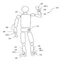
図1を参照すると、検知ユニット100を有する本開示の実施形態の実装の一例が、例えば関節106により連結された複数の可動セグメント104を有する解剖学的身体102のような移動体と関連して提示されている。具体的には、限られた数の検知ユニット100、例えば、わずか約4つの装着式または着用式の検知ユニット100を用いて、トラッキング対象102のセグメント104の1つ以上に結合することができる。図1に示した特定の実施形態では、例えば、2つの検知ユニット100を対象体102の手首106−1に近接して取り付け、さらに2つの検知ユニット100を足首106−2に近接して取り付けることができる。異なる実施形態では、例えば、第5の検知ユニット100を対象体102の中心に取り付けることもできる。尚、より少ないまたは追加の検知ユニット100を、添付の特許請求の範囲から逸脱することなく、身体102または他の被トラッキング物に同様のまたは代替の配置で採用することができることが理解されるだろう。
Referring to FIG. 1, an example of an implementation of an embodiment of the present disclosure having a
一実施形態では、検知ユニット100は、3D加速度計、3Dジャイロスコープ、3D磁力計等のいずれか1つ以上を備えることができる。別の実施形態では、検知ユニット100は、代替的にまたは付加的に、圧力センサと、測距ユニット、または検知ユニット100間の相対距離を評価するための手段を備えることができる。さらなる変形形態では、適切な検知ユニット及び/または測距ユニットの他の組み合わせを用いることができる。ここで開示される実施形態は例示のみを目的とすること、所望の応用に応じて、代替となる、異なる検知手段及び/または測距手段の組み合わせ、配置または部分要素を用いることができることが理解されるだろう。磁気的に妨害される環境を伴う応用の場合、例えば、ジャイロスコープ及び加速度計のセンサ指示値のみを用いることができる。別の変形形態では、3D加速度計、3Dジャイロスコープ及び3D磁力計を、例えば、圧力センサのみと統合することができる。
In one embodiment, the
検知ユニット間の相対距離は種々のテクノロジーや技術により得られる。双方向測距おオペレーションモードで超広帯域(UWB)無線を使用する場合、例えば、関連する無線トランシーバにより一対の所与の検知ユニット100間の相対距離の測定手段を直接的に得ることが可能である。加えて、音響信号を使用する場合、例えば、専用の無線テクノロジー、例えば米国特許出願公開第2011/0109438号明細書に開示される無線通信プロトコルを用いて、検知ユニット100を(およそマイクロ秒範囲の分解能で)同期させることが可能である。このような方法では、オーディオトランスミッタとオーディオレシーバとの間の単一の伝送の飛行時間(time−of−flight;TOF)を、このようなノードは共通の基準クロックを共有しているので、これに空気中の音速を直接乗算することにより、即座に対応する距離に変換することが可能である。
The relative distance between the sensing units can be obtained by various technologies and techniques. When using ultra-wideband (UWB) radio in the two-way ranging mode of operation, it is possible, for example, to obtain directly the means of measuring the relative distance between a given pair of sensing
さらに、音響信号を用いる場合、音の伝播速度が比較的低いため、通常、1秒あたりの距離伝送の大幅な増加が許容されておらず、よって、共通の基準クロックに従って同期されるノード間の測距が容易である。特に、2つのノード間の一対の伝送により距離推定値が1つだけ得られる双方向測距オペレーションとは異なり、トランスミッタノードと複数のレシーバノードとの間の距離推定値を得るために必要なのは単一のブロードキャストまたは伝送のみである。対照的に、例えば、UWBトランシーバを使用して無線信号を用いる場合、関連パケット持続時間は170マイクロ秒程度と低くてもよく、よって、すべての所与の着用式検知ユニット100間で高速の測距更新を潜在的に許容している。図1には、トラッキングモジュール107についても、ユーザが身に着けているスマートフォン装置上で実装される具体例で示している。異なる実施形態では、トラキングモジュールは、代替的に、ユーザの身体上またはそのすぐ近くに配置されるタブレット、パーソナルコンピュータ、またはコンソールゲーム機上に実装することができる。トラッキングモジュールの実装及び機能の例は以下に明らかにする。
In addition, when using acoustic signals, the relatively low speed of sound propagation typically does not allow for a significant increase in distance transmission per second, and thus between nodes synchronized according to a common reference clock. Distance measurement is easy. In particular, unlike a bidirectional ranging operation where only one distance estimate is obtained by a pair of transmissions between two nodes, it is only necessary to obtain a distance estimate between a transmitter node and multiple receiver nodes. Only one broadcast or transmission. In contrast, for example, when using a wireless signal using a UWB transceiver, the associated packet duration may be as low as 170 microseconds, thus providing fast measurement between all given
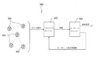
次に図2を見ると、複数の連結されたセグメント104を有する図1の解剖学的身体102のような移動体のモーショントラッキングを行うシステム200の実施形態の一例が概略的に開示されている。このモーショントラッキングシステム200は、通常、一組の検知ユニット202と、トラッキングモジュール204と、データベースモジュール206を備えることができる。図示のように、このシステム200は、それぞれ対応するセグメント104及び/または、例えば図1の対象体102の手首106−1や足首106−2のような関節106に取り付けることができる限られた数の検知ユニット202を用いることができる。さらに、検知ユニット202は、対応するセグメント104及び/または関節106の所望のパラメータを測定するための3D加速度計、3Dジャイロスコープ、3D磁力計及びその他の検知手段の適切な組み合わせを備えることができる。検知ユニット202の代替的な組み合わせ及び配置は当業者には明らかであろう。
Turning now to FIG. 2, an example embodiment of a
図2の検知ユニット202は、対応するセグメント104の姿勢、方向、動作、位置、速度、加速度、角速度、近接及び/または他の関連パラメータを表示するセンサ信号を生成するように構成することができる。図示のように、センサ信号は、さらに、有線手段及び/または無線手段を介してトラッキングモジュール204に送信することができる。受信したセンサ信号をもとに、トラッキングモジュール204は、通常、被トラッキングセグメント104の方向を決定するとともに被トラッキングセグメント104の新たな位置またはその位置における対応する変化を算出することができる。トラッキングモジュール204は、付加的に、セグメント104の方向や予測位置といった被トラッキングパラメータまたは特徴をデータベースモジュール206に送信することができる。これに応答して、データベースモジュール206は、被トラッキング物102の全体姿勢をトラッキングモジュール204から与えられた特徴と関連付けて、当該イテレーションで得られた物体102の姿勢に関わる情報を出力することができる。データベースモジュール206は、さらに、姿勢情報をフィードバックとしてトラッキングモジュール204に返送することができ、トラッキングモジュール204は、その後のイテレーションを補正するための基準または手段としてこれを利用することができる。
The
さらに、図2のデータベースモジュール206は、モーショントラッキングシステム200内の独立した構成要素として図示されているが、このような分離は便宜的に示しただけであること、実際の実装は様々でありうることが理解されるであろう。例えば、一実施形態では、データベースモジュール206は、集中的に(例えば、ユーザが所持しているスマートフォン内またはトラッキングモジュール204が使用する検知ユニット202の1つの内部に設けられて)または分散的に(例えば、検知ユニット202のそれぞれまたはこのいくつかの内部に配置されて)着用配置内に組み込むことができる。別の実施形態では、データベースモジュール206は、物理的に離れた場所ではあるが、着用配置の比較的ごく近くに、例えば、コンピュータ、タブレット、コンソールゲームハードウェアなどの中に存在することができる。さらに別の実施形態では、データベースモジュール206は、着用配置から遠く離れて、例えば、権限を有する多数のユーザまたはグループが動的アクセスを有することができる集中グローバルデータベースの形態で置くことができる。このような配置の1つでは、トラッキングモジュール204は、例えばWiFiやLTE、または他の適切な通信プロトコルを介して、モーションキャプチャセッションの間グローバルデータベースと通信することができる。このような配置の別の1つでは、グローバルデータベースの関連部分をモーショントラッキングセッションの開始時にダウンロードし、これを用いて、セッションの間トラッキングモジュール204がアクセス可能なローカルデータベースを生成することができる。このローカルデータベースは、例えば、ユーザ固有パラメータ(例えば、身体寸法、トレーニングレベル等)に従って、及び/またはトラッキングする特定の行為または動作(例えば、歩行、ランニング、運動、ゲーム等)に従って生成することができる。特定の行為または動作に関わる情報は、ユーザにより直接入力されても、関連分類アルゴリズムにより与えられてもよい。一実施形態では、データベースは専用のオフライントレーニンフェーズで生成される。異なる実施形態では、データベースは、例えば既知の教師なし学習アルゴリズムを用いて、動作に関する特定のユーザ特性に従って動的に拡張することが可能である。
Further, while the
図2の特定の例では、トラッキングモジュール102は、検知ユニット202により与えられるセンサ信号に対してセンサ・フュージョン技術を適用して、例えば所与の地理的位置にもとづく重力及び磁北により定義されるローカル基準フレームと関連して表される、k番目のサンプルタイムにおけるn番目の検知ユニット202(nは1〜N、Nは使用中の検知ユニット202の総数)の方向
![]()

![]()
![]()
![]()
![]()
![]()
![]()
![]()
![]()
![]()
![]()
![]()
引き続き図2のモーショントラッキングシステム200の一例を参照すると、トラッキングモジュール204により決定される検知ユニット202の方向
![]()
![]()
データベースモジュール206は、様々な基準のいずれか1つ以上をもとに最も近似した姿勢を選択することができる。一実装において、例えば、データベースモジュール206は、(トラッキングモジュール204により特徴づけられた)被トラッキングセグメント104の特徴と、(予め定義された姿勢において特徴づけられた)対応するセグメント104の特徴との間で測定された重み付き距離の点で最も不一致度が小さい姿勢を選択することができる。このような重み付き距離は、例えば、特徴空間におけるユークリッド距離を用いて測定することができる。別の実装では、データベースモジュール206は、一組の近似姿勢、または対応する被トラッキングセグメント104との重み付き距離の不一致度が極小であるセグメント104を有する姿勢から導出した平均姿勢にもとづく姿勢を選択することができる。さらに別の実装では、先の姿勢選択を用いて、被トラッキング体102またはそのセグメント104の具体的な動作を予測または推測することができる。このような例の1つでは、データベースモジュール206は、イテレーション間の動作または移行がよりスムーズな出力を行うために、先に選択した姿勢に最も近似する一組の予め定義された姿勢を優先するように構成することができる。別の関連する例では、マルコフモデルを用いて、時間に対する一定の姿勢間遷移確率を関連付けることができる。例えば、関連状態遷移マトリクスは、姿勢データベースの生成に使用したものと同じトレーニングフェーズにおいて、恐らくは既知の次元削減技術と併せて得ることができる。さらに別の関連する例では、先に推定または選択した一組の姿勢から動的モデルを生成して、これを用いて新たな姿勢を予測することができる。代替の変形形態では、モーショントラッキングシステム200またはデータベースモジュール206は、関連技術において一般に用いられる他の適切な機械学習技術に従って構成することができる。
The
再び図2のトラッキングモジュール204を参照すると、トラッキングモジュール204が自由加速度またはその二重積分をもとに位置を算出するための上記(1)の関係は、比較的短い時間フレームに適用される時はほぼ正確な結果を得られるが、より長いタイムスパンではドリフトする傾向もある。例えば比較的小さく安価なMEMSセンサからなる3D加速度計及び3Dジャイロスコープを用いる場合、約1秒以下の時間フレーム内では、通常、誤差は無視できる程度である。しかしながら、このような時間フレームを超えると、集合的な位置ドリフトによりかなりの誤差が生じる。この問題に対処すべく、例えば、図2に図示するようにデータベースモジュール206の出力をトラッキングモジュール204にフィードバックすることができる。特に、所与のトラッキングセッションが一組の連結されたセグメント104内に限定され、その位置推定値は、該連結されたセグメント104のモデルにより効果的に制約される。これは、潜在的に即座の正確な結果を可能にするだけでなく、長期にわたる基本的にドリフトフリーな一致を可能とする。例えば、被トラッキング体102の手首106−1に配置された検知ユニット202は2メートル程度以下だけ離すことができる。例えば、基準セグメント104に対する検知ユニット202の位置は、推定された全身姿勢から抽出してトラッキングモジュール204に送信することができる。具体的な姿勢推定値の精度は時折(数センチメートルの範囲で)変動しうるが、それでも、フィードバック情報により、上記(1)の関係で特徴づけられる位置に対する自由加速度の積分の長期の安定化が可能となる。例えば、データベース駆動型の位置測定は以下によりモデル化することが可能である。
結果として得られる、データベースモジュール206により推定された姿勢の精度は、限られた数の検知ユニット202のみを用いて高忠実度のトラッキングを提供するのに十分であろう。例えば、データベースモジュール206は、4つまたは5つの検知ユニット202を用いて、グランドトゥルースに対して、方向については数度のみ、位置については数センチのみの誤差の全身モーショントラッキングを行うことができる。これは、方向及び位置の両方のセンサ信号を、データベースモジュール206に入力するパラメータまたは特徴として用いているためである。方向関連パラメータまたは特徴のみにもとづくと、例えば、様々な動作を網羅するのに十分な性能が得られる。しかしながら、よりルーチン的な動作または移動では、再現される動作においてあいまいさが生じる。
The resulting pose accuracy estimated by the
以上、基本セグメント104に対する身体姿勢の推定について説明したが、外部の基準フレームに対する被トラッキング物102の絶対姿勢のトラッキングが所望される他の応用もある。これは、例えば、利用可能な加速度センサ信号を、重力要素を差し引いた後にローカルフレームにおいて積分することで達成される。積分に起因するドリフトは、ある程度は、身体セグメント104の1つ以上とその所定の周囲環境との間の接触をもとに制御することができる。例えば、周囲環境との接触が検出されたとき、ゼロ重力または位置更新を適用してドリフトを制限することができる。
Although the estimation of the body posture with respect to the
限られた数の検知ユニット202しか有していないので、検知ユニット202が取り付けられていないセグメント104の動態を直接測定することは不可能であろう。例えば、検知ユニット202が被トラッキング体102の手首106−1及び足首106−2のみに設けられているときには、該被トラッキング体102の足セグメント104と所定の周囲環境との接触を断定的に検出することは難しいであろう。このような欠点を緩和するために、データベースのトレーニングまたは学習フェーズと同じように、接触点情報をアーキテクチャフレームワークに組み込み、データベースモジュール206が被トラキング体102とその周囲環境との間の起こりうる接触点についての関連する記述を含むようにすることができる。具体的な接触点パラメータまたは特徴は、トラッキングモジュール204により算出することができ、同様にデータベースモジュール206がこれを用いて接触発生の推定値を出すことができる。このようなパラメータまたは特徴は、検知ユニット202の加速度、速度または位置のいずれか1つ以上に関わる情報、セグメント104の方向、加速度、速度または位置のいずれか1つ以上に関わる情報、または全体的な身体姿勢に関する統計に関わる情報(例えば、質量中心、圧力中心等)を含むことができる。
With only a limited number of
次に図3を参照すると、複数の連結されたセグメント104を有する図1の解剖学的身体102のような移動体のモーショントラッキングを行うシステム300の実施形態の別の例が概略的に提示されている。先の実施形態のように、このモーショントラッキングシステム300は、通常、被トラッキングセグメント104の様々な測定値に対応する1つ以上のセンサ信号をトラッキングモジュール304に送信する限られた数の検知ユニット302を備えることができる。トラッキングモジュール304は、被トラッキングセグメント104のある特定のパラメータまたは特徴を算出または推定し、さらに処理するためにデータベースモジュール306に送信することができる。次に、データベースモジュール306は、当該イテレーションついて決定された移動体102の姿勢に関する情報を出力することができ、さらに、その後のイテレーションで用いるために、測定値更新をフィートバックとしてトラッキングモジュール304に与えることができる。
Referring now to FIG. 3, another example of an embodiment of a
図2の実施形態と同様に、図3のシステム300の検知ユニット302は、被トラッキング体102の対応するセグメント104及び/または関節106の所望のパラメータまたは特徴を測定するための、3D加速度計、3Dジャイロスコープ、3D磁力計の適切な組み合わせを備えることができる。精度、安定性及び全体的なトラッキング性能の向上のために、検知ユニット302は、さらに、圧力センサまたは圧力検知手段と、検知ユニット302間の相対距離の直接的なまたは派生的な測定手段を提供することが可能な測距ユニットまたは測距手段が組み込むことができる。より詳細には、圧力センサは、例えば以下の圧力と高さとの関係を用いて、対応する検知ユニット302の高さを測定するための手段を提供することが可能である。
しかしながら、上記疎結合アプローチは追加の考慮を必要とすることがある。例えば、ノードの実際の位置はまず並進と回転を解かなくては知ることができず、その位置を適切に推定するためには、距離推定値を備えた比較的多数の検知ユニット302が必要である。具体的には、解くべき未知数の数は、(3つの非同一線上のノードを選択することにより、N*3個の未知の位置座標一式から原点及びx−y軸を定義する6つの未知数を除いて)(N−2)*3とすることができる。この特定の未知数の数により、ノード位置を推定するにはだいたい5つまたはそれ以上の検知ユニット302を必要とすることがある。加えて、オクルージョンが頻繁に起こりうる着用式センサ配置を伴う応用においては、外れ値や信号妨害を適切に補償するために、実質的にはより多くの検知ユニット302を必要とすることがある。したがって、このような考慮事項に対処するために、上述した疎結合アプローチを密結合アプローチと置き換えることができる。より具体的には、各相対距離を入手可能な場合は、これを、例えば以下をもとに、図3のトラッキングモジュール302において測定値更新として直接的に用いることができる。
高さ及び距離の更新は、通常は有益であるが、ある一定の使用事例では全体的なトラッキング応用の安定性を妨げることがあることが容易に理解されるであろう。例えば、ある1つの検知ユニット302が、その他の検知ユニット302との関連で長時間にわたって妨害される状況(実際には対象体102による長時間のオクルージョンによりルーチン的に起こる)において、関連フレークワークの水平面内の各セグメント104の位置が観測不可能となり、望ましくないトラッキング結果となりうる。MEMSタイプの慣性センサを用いた応用では、このようなオクルージョンは、潜在的にかなりの誤差を引き起こし、わずか1秒のトラッキング時間で結果を容認できないものにしうる。したがって、データベースモジュール302により推定された姿勢から得られる位置
このような実施形態の1つでは、被トラッキングセグメント104の特徴と対応するデータベースセグメント104の特徴との間で測定された距離に、固定名称に従って重み付けをする。例えば、各特徴クラス(例えば、方向や位置)に対して、全体の重みのうち予め定めた比率をヒューリスティックに結びつけることができ、さらに、これを同じクラス内の全特徴間で等しく分割することができる。
In one such embodiment, the distance measured between a feature of the tracked
別の関連実施形態では、被トラッキングセグメント104の特徴と対応するデータベースセグメント104の特徴との間で測定された距離の重みは、動的に調整されてトラッキングモジュール304からデータベースモジュール306に送信される。可能な実装の1つでは、方向及び位置の推定値の不確かさは、例えば適用されるセンサ・フュージョン技術により決まるが、これを用いて特徴間で測定された距離の各重みを制御することができる。したがって、例えば、特定のノードに対する距離更新が長時間利用できない場合、このノードの位置推定値の不確かさが大きくなり、データベースモジュール306は対応する位置特徴に結びつける重み値を小さくして、これが全体的な姿勢検知プロセス与える影響を減少させる。さらに別の可能な実装では、位置測定値の更新により得られる残差値を用いて重み付けシステムを調整することができる。例えば、データベース駆動型の位置更新を行って比較的大きい位置ベース残差が生じた場合、これは、トラッキングモジュール304とデータベースモジュール306との間で位置推定値が一致していないことを示していることになるだろう。これに応じて、データベースモジュール306は、対応する位置特徴に割り当てる重みを下げて、これにより生じる悪影響を減少させる。また、例えばジャイロスコープセンサが飽和した場合、しばらくの間方向の精度が悪化することがある。対応する方向特徴の重みを下げることにより、より好ましい結果が得られ、全体的な性能を向上させることができる。
In another related embodiment, the weight of the distance measured between the feature of the tracked
図5は、本例では5つの検知ユニットを用いて、開示したシステム及び技術で達成可能なRMS全身セグメント位置誤差の例を、それぞれ異なる動作ついて、また、それぞれ異なる検知モダリティの組み合わせについて示している。これらの誤差は、従来の17個のセンサを用いた全身モーションキャプチャにより得られる結果と対比して評価されている。この解決策は、再現されるセグメント位置においておよそ数センチメートルのみの誤差で正確なモーション再現結果を得ることができることがわかる。さらなる例として、図6は、3つの異なる動作について、現場をビデオ録画した場合のスナップショット例と、17個のセンサによる全身モーションキャプチャと、提案した、センサ数を減らしたモーション再現を示している。この場合も、高レベルのモーション再現忠実度が達成されたことが明らかである。 FIG. 5 illustrates examples of RMS whole body segment position errors achievable with the disclosed system and technique, with five sensing units in this example, for different operations and for different combinations of sensing modalities. . These errors have been evaluated against the results obtained by conventional whole body motion capture using 17 sensors. It can be seen that this solution can provide accurate motion reproduction results with an error of only a few centimeters at the segment position to be reproduced. As a further example, FIG. 6 shows an example snapshot of a video recording of the scene, a full body motion capture with 17 sensors, and a proposed motion reproduction with a reduced number of sensors for three different actions. . Again, it is clear that a high level of motion reproduction fidelity has been achieved.
上記各モーショントラッキングシステム200,300とそのトラッキングモジュール204,206及びデータベースモジュール206,306、並びにこれらの変形例は、センサ信号を処理して、上述の機能、または例えば図4のアルゴリズムまたは方法400により概説するような機能を行うように適応させたまたはプログラムされたコントローラ、マイクロコントローラ、プロセッサ、マイクロプロセッサ等を有する、検知ユニット100,202,302内に配設される慣性デジタル信号処理(DSP)電気回路構成の組み合わせ、あるいは1つ以上のコンピューティングデバイスを用いて実装することができる。
Each of the
図4におおまかに概説された方法400の各イテレーションにおいて、トラッキングモジュール204,304は、まず、ステップ400−1において、関連の検知ユニット100,202,302からのセンサ信号の1つ以上を受信するように構成することができる。トラッキングモジュール204,304は、このセンサ信号をもとに、ステップ400−2において被トラッキングセグメント104の対応する3次元方向を推定し、さらに、ステップ400−3において被トラッキングセグメント104の対応する3次元位置を決定するように構成することができる。付加的なまたは任意のステップ400−4aにおいて、トラッキングモジュール204,304は、センサ信号をもとに、被トラッキングセグメント104の算出された3次元位置に対して必要な補正を加えるように構成することができる。ステップ400−4bにおいて、トラッキングモジュール204,304は、データベースモジュールからの補正を加える。さらに、トラッキングモジュール204,304は、さらなる処理のために、ステップ400−5において、評価済みの特徴、例えば被トラッキングセグメント104の3次元方向や3次元位置などをデータベースモジュール206,306に送信するように構成することができる。
In each iteration of the
データベースモジュール206,306は、トラッキングモジュール204,304により送信された特徴を受信すると、ステップ400−6において対象体102の全身姿勢を被トラッキングセグメント104の3次元方向及び3次元位置と関連付けるように構成することができる。より詳細には、物体102の姿勢を、トラッキングモジュール204,304により与えられるセグメント特徴をもとに推定して、例えば、上記実施形態と併せて考察したように、被トラッキング物102の予め定義された予測姿勢のデータベースから選択することができる。所与のイテレーションについての被トラッキング物102の推定姿勢に関する対応情報は、その後、データベースモジュール206,306により出力し、モーショントラッキングシステム200,300と通信することができる1つ以上の補助装置に供給することができる。ステップ400−7において、データベースモジュール206,306は、さらに、被トラッキング物102の推定姿勢を、例えばフィードバックとして使用するためにまたはその後のイテレーションでの測定値の更新のために、トラッキングモジュール204,304の入力に返送するように構成することができる。例えば、推定姿勢は、ステップ400−4bに返送することができる。
Upon receiving the features transmitted by the tracking
本開示により、複数の連結された可動セグメントを有する移動体のモーショントラッキングシステム及び方法が提供されることが理解されるであろう。いくつかの実施形態のみを挙げたが、当業者にとっては、上記記述から代替形態及び変形形態が明らかであろう。これらの及びその他の代替形態は、同等物であり、且つ本開示及び添付の請求項の趣旨及び範囲に含まれると考えられるものである。 It will be appreciated that the present disclosure provides a mobile motion tracking system and method having a plurality of connected movable segments. While only some embodiments have been given, alternatives and modifications will be apparent to those skilled in the art from the above description. These and other alternatives are equivalent and are contemplated to be within the spirit and scope of the present disclosure and the appended claims.
Claims (31)
前記セグメントの一部に結合され、当該セグメントの1つ以上の特徴に対応するセンサ信号を生成するように構成された検知ユニットと、
前記検知ユニットと通信しており、前記センサ信号をもとに少なくとも前記セグメントの3次元方向及び3次元位置を決定するように構成されたトラッキングモジュールと、
前記トラッキングモジュールと通信しており、前記移動体の姿勢を前記セグメントの前記3次元方向及び前記3次元位置と関連付けるように構成されたデータベースモジュールを備えたシステム。 A motion tracking system for a mobile object having a plurality of connected segments,
Coupled to a portion of the segment, and configured test known units to generate a sensor signal corresponding to one or more characteristics of the segment,
A tracking module in communication with the sensing unit and configured to determine at least a three-dimensional direction and a three-dimensional position of the segment based on the sensor signal;
A system in communication with the tracking module and comprising a database module configured to associate a posture of the mobile with the three-dimensional direction and the three-dimensional position of the segment.
前記検知ユニットから1つ以上のセンサ信号を受信すること、
前記センサ信号をもとにトラッキングモジュールにおいて前記セグメントの3次元方向を推定すること、
前記センサ信号をもとに前記トラッキングモジュールにおいて前記セグメントの3次元位置を予測すること、
前記セグメントの前記推定された3次元方向及び前記セグメントの前記予測された3次元位置をデータベースモジュールに送信すること、
前記データベースモジュールにおいて、前記セグメントを含む前記移動体の姿勢を、前記トラッキングモジュールから送信された前記セグメントの前記3次元方向及び前記3次元位置と関連付けること、
前記移動体の前記関連付けられた姿勢を前記データベースモジュールから前記トラッキングモジュールに送信し、前記トラッキングモジュールにおいてこの姿勢をもとに前記セグメントの前記予測された3次元位置を補正することを含む方法。 Motion tracking of a moving body having a plurality of connected segments, a method using a test known unit coupled to one or more of said segments,
Receiving one or more sensor signals from the sensing unit;
Estimating a three-dimensional direction of the segment in a tracking module based on the sensor signal;
Predicting a three-dimensional position of the segment in the tracking module based on the sensor signal;
Transmitting the estimated three-dimensional direction of the segment and the predicted three-dimensional position of the segment to a database module;
In the database module, associating the posture of the moving object including the segment with the three-dimensional direction and the three-dimensional position of the segment transmitted from the tracking module ;
The method comprising the the associated orientation of the moving body is transmitted from the database module to the tracking module, for correcting the predicted 3-dimensional position before Symbol segment on the basis of this position in the tracking module.
前記付加的な特徴は、前記検知ユニットと関連する前記セグメントの1つ以上についての速度、加速度及び位置の1つ以上を含み、前記移動体と所定の周囲環境との間の接触を検出できるように前記付加的な特徴を前記データベースモジュールに送信すること、
前記移動体と前記所定の周囲環境との間の検出された接触をもとに前記移動体の速度測定値及び位置測定値の1つ以上を更新することをさらに含む請求項10記載の方法。 Calculating additional features of the segment in the tracking module;
The additional features include one or more of speed, acceleration, and position for one or more of the segments associated with the sensing unit so that contact between the mobile and a predetermined surrounding environment can be detected. Sending the additional features to the database module;
The method of claim 10, further comprising updating one or more of a velocity measurement and a position measurement of the mobile based on detected contact between the mobile and the predetermined surrounding environment.
前記検知ユニットから1つ以上のセンサ信号を受信すること、
前記センサ信号をもとにトラッキングモジュールにおいて前記セグメントの3次元方向を推定すること、
前記センサ信号をもとに、前記トラッキングモジュールにおいて前記セグメントの3次元位置を先に予測された3次元位置を用いて予測すること、
前記セグメントの前記推定された3次元方向及び前記セグメントの前記予測された3次元位置をデータベースモジュールに送信すること、
前記データベースモジュールにおいて、前記セグメントを含む前記移動体の姿勢を、前記トラッキングモジュールから送信された前記セグメントの前記3次元方向及び前記3次元位置と関連付けること、
前記移動体の前記関連付けられた姿勢を前記データベースモジュールから前記トラッキングモジュールに送信し、前記トラッキングモジュールにおいてこの姿勢をもとに前記セグメントの前記予測された3次元位置を補正することを含む方法。 The motion capture of a moving body having a plurality of connected segments, a method using a test known unit coupled to one or more of said segments,
Receiving one or more sensor signals from the sensing unit;
Estimating a three-dimensional direction of the segment in a tracking module based on the sensor signal;
Based on the sensor signal, predicting the three-dimensional position of the segment in the tracking module using the previously predicted three-dimensional position ;
Transmitting the predicted 3-dimensional position of the three-dimensional direction and the segment in which the estimated before Symbol segment database module,
In the database module, associating the posture of the moving object including the segment with the three-dimensional direction and the three-dimensional position of the segment transmitted from the tracking module ;
The method comprising the the associated orientation of the moving body is transmitted from the database module to the tracking module, for correcting the predicted 3-dimensional position before Symbol segment on the basis of this position in the tracking module.
前記付加的な特徴は、前記検知ユニットと関連する前記セグメントの1つ以上についての速度、加速度及び位置の1つ以上を含み、前記移動体と所定の周囲環境との間の接触を検出できるように前記付加的な特徴を前記データベースモジュールに送信すること、
前記移動体と前記所定の周囲環境との間の検出された接触をもとに前記移動体の速度測定値及び位置測定値の1つ以上を更新することをさらに含む請求項20記載の方法。
Calculating additional features of the segment in the tracking module;
The additional features include one or more of speed, acceleration, and position for one or more of the segments associated with the sensing unit so that contact between the mobile and a predetermined surrounding environment can be detected. Sending the additional features to the database module;
21. The method of claim 20, further comprising updating one or more of a velocity measurement and a position measurement of the mobile based on detected contact between the mobile and the predetermined surrounding environment.
Applications Claiming Priority (3)
| Application Number | Priority Date | Filing Date | Title |
|---|---|---|---|
| US14/151,409 | 2014-01-09 | ||
| US14/151,409 US10415975B2 (en) | 2014-01-09 | 2014-01-09 | Motion tracking with reduced on-body sensors set |
| PCT/IB2015/000700 WO2015114468A2 (en) | 2014-01-09 | 2015-01-09 | Motion tracking with reduced on-body sensors set |
Publications (2)
| Publication Number | Publication Date |
|---|---|
| JP2017511906A JP2017511906A (en) | 2017-04-27 |
| JP6668239B2 true JP6668239B2 (en) | 2020-03-18 |
Family
ID=53491633
Family Applications (1)
| Application Number | Title | Priority Date | Filing Date |
|---|---|---|---|
| JP2016536188A Active JP6668239B2 (en) | 2014-01-09 | 2015-01-09 | Motion tracking using a reduced number of wearing sensor sets |
Country Status (4)
| Country | Link |
|---|---|
| US (1) | US10415975B2 (en) |
| EP (1) | EP3063499A2 (en) |
| JP (1) | JP6668239B2 (en) |
| WO (1) | WO2015114468A2 (en) |
Families Citing this family (33)
| Publication number | Priority date | Publication date | Assignee | Title |
|---|---|---|---|---|
| KR20150089371A (en) * | 2014-01-27 | 2015-08-05 | 한국전자통신연구원 | Apparatus for analyzing human motion |
| US9926832B2 (en) | 2015-04-24 | 2018-03-27 | Briggs & Stratton Corporation | Reverse fin cooling fan |
| WO2017021965A2 (en) * | 2015-08-06 | 2017-02-09 | Upright Technologies Ltd. | Body movement feedback system and method |
| US10222450B2 (en) * | 2015-10-12 | 2019-03-05 | Xsens Holding B.V. | Integration of inertial tracking and position aiding for motion capture |
| US20180070864A1 (en) * | 2016-06-02 | 2018-03-15 | Matthew Schuster | Methods and devices for assessing a captured motion |
| JP6973388B2 (en) * | 2016-06-16 | 2021-11-24 | ソニーグループ株式会社 | Information processing equipment, information processing methods and programs |
| FR3054048B1 (en) | 2016-07-13 | 2018-08-24 | Commissariat Energie Atomique | METHOD AND SYSTEM FOR REAL-TIME HIERARCHICAL CONTROL OF AN ARTICULATED STRUCTURE OPERATING A LIMITED NUMBER OF MOTION SENSORS |
| CN106073794A (en) * | 2016-08-23 | 2016-11-09 | 吉林大学 | A kind of wearable lower limb rehabilitation tempers gait monitoring analytical equipment |
| WO2018081795A1 (en) | 2016-10-31 | 2018-05-03 | Zipline Medical, Inc. | Systems and methods for monitoring physical therapy of the knee and other joints |
| US20180342109A1 (en) * | 2017-05-25 | 2018-11-29 | Thomson Licensing | Determining full-body pose for a virtual reality environment |
| US10521947B2 (en) * | 2017-09-29 | 2019-12-31 | Sony Interactive Entertainment Inc. | Rendering of virtual hand pose based on detected hand input |
| EP3732549B1 (en) * | 2017-12-29 | 2022-06-29 | Fraunhofer-Gesellschaft zur Förderung der angewandten Forschung e.V. | Method for predicting a motion of an object and method for generating a virtual reality view |
| JP2019138812A (en) * | 2018-02-13 | 2019-08-22 | 日本電信電話株式会社 | Distance measuring device, distance measuring system, and method for measuring distance |
| JP6874207B2 (en) * | 2018-03-01 | 2021-05-19 | 株式会社ソニー・インタラクティブエンタテインメント | Estimator, estimation method and program |
| WO2019203189A1 (en) * | 2018-04-17 | 2019-10-24 | ソニー株式会社 | Program, information processing device, and information processing method |
| US11054638B2 (en) | 2018-06-13 | 2021-07-06 | Reavire, Inc. | Tracking pointing direction of device |
| IT201800006950A1 (en) | 2018-07-05 | 2020-01-05 | Kinematic detection and monitoring system of body movements in water, and related method | |
| GB2574074B (en) | 2018-07-27 | 2020-05-20 | Mclaren Applied Tech Ltd | Time synchronisation |
| US10817047B2 (en) | 2018-09-19 | 2020-10-27 | XRSpace CO., LTD. | Tracking system and tacking method using the same |
| US20200097066A1 (en) * | 2018-09-20 | 2020-03-26 | XRSpace CO., LTD. | Tracking Method and Tracking System Using the Same |
| WO2020142047A1 (en) * | 2018-12-31 | 2020-07-09 | Havelsan Hava Elektronik Sanayi Ve Ticaret Anonim Sirketi | System for detecting, analysing and following movement |
| US11107242B2 (en) * | 2019-01-11 | 2021-08-31 | Microsoft Technology Licensing, Llc | Detecting pose using floating keypoint(s) |
| GB201906420D0 (en) | 2019-05-07 | 2019-06-19 | Farley Adam | Virtual augmented and mixed reality systems with physical feedback |
| US11460914B2 (en) | 2019-08-01 | 2022-10-04 | Brave Virtual Worlds, Inc. | Modular sensor apparatus and system to capture motion and location of a human body, body part, limb, or joint |
| GB2588236B (en) | 2019-10-18 | 2024-03-20 | Mclaren Applied Ltd | Gyroscope bias estimation |
| EP3832435A1 (en) * | 2019-12-06 | 2021-06-09 | XRSpace CO., LTD. | Motion tracking system and method |
| KR102421310B1 (en) * | 2020-07-21 | 2022-07-14 | 한국해양대학교 산학협력단 | Smart walking aid apparatus and method for rehabilitation of parkinson's patient |
| US11696704B1 (en) | 2020-08-31 | 2023-07-11 | Barron Associates, Inc. | System, device and method for tracking the human hand for upper extremity therapy |
| US11507179B2 (en) * | 2020-09-17 | 2022-11-22 | Meta Platforms Technologies, Llc | Systems and methods for predicting lower body poses |
| US11651625B2 (en) | 2020-09-17 | 2023-05-16 | Meta Platforms Technologies, Llc | Systems and methods for predicting elbow joint poses |
| US11887259B2 (en) | 2021-01-25 | 2024-01-30 | Walker L. Sherk | Method, system, and apparatus for full-body tracking with magnetic fields in virtual reality and augmented reality applications |
| CN114562993A (en) * | 2022-02-28 | 2022-05-31 | 联想(北京)有限公司 | Track processing method and device and electronic equipment |
| CN116019442B (en) * | 2022-12-12 | 2024-05-14 | 天津大学 | Motion posture assessment system based on UWB/IMU fusion |
Family Cites Families (13)
| Publication number | Priority date | Publication date | Assignee | Title |
|---|---|---|---|---|
| JP2915846B2 (en) * | 1996-06-28 | 1999-07-05 | 株式会社エイ・ティ・アール通信システム研究所 | 3D video creation device |
| JP3862348B2 (en) * | 1997-03-19 | 2006-12-27 | 東京電力株式会社 | Motion capture system |
| JP3668663B2 (en) * | 2000-02-21 | 2005-07-06 | 日本電信電話株式会社 | Motion input method and apparatus in virtual space and recording medium recording the motion input program |
| US6984208B2 (en) * | 2002-08-01 | 2006-01-10 | The Hong Kong Polytechnic University | Method and apparatus for sensing body gesture, posture and movement |
| NL1030440C2 (en) | 2005-11-16 | 2007-05-21 | Univ Twente | Motion tracking system. |
| EP1970005B1 (en) * | 2007-03-15 | 2012-10-03 | Xsens Holding B.V. | A system and a method for motion tracking using a calibration unit |
| JP2008307207A (en) * | 2007-06-14 | 2008-12-25 | Advanced Telecommunication Research Institute International | Action measuring instrument |
| KR101483713B1 (en) | 2008-06-30 | 2015-01-16 | 삼성전자 주식회사 | Apparatus and Method for capturing a motion of human |
| JPWO2010027015A1 (en) * | 2008-09-05 | 2012-02-02 | 国立大学法人 東京大学 | Motion capture device |
| GB0901020D0 (en) | 2009-01-21 | 2009-03-04 | Birmingham City University | A motion capture apparatus |
| JP2010176380A (en) * | 2009-01-29 | 2010-08-12 | Sony Corp | Information processing device and method, program, and recording medium |
| EP2320288B1 (en) | 2009-11-06 | 2016-12-21 | Xsens Holding B.V. | A method and a system for enabling a wireless communication between a master unit and a sensor unit |
| US9436286B2 (en) * | 2011-01-05 | 2016-09-06 | Qualcomm Incorporated | Method and apparatus for tracking orientation of a user |
-
2014
- 2014-01-09 US US14/151,409 patent/US10415975B2/en active Active
-
2015
- 2015-01-09 JP JP2016536188A patent/JP6668239B2/en active Active
- 2015-01-09 WO PCT/IB2015/000700 patent/WO2015114468A2/en active Application Filing
- 2015-01-09 EP EP15732329.6A patent/EP3063499A2/en not_active Withdrawn
Also Published As
| Publication number | Publication date |
|---|---|
| WO2015114468A3 (en) | 2015-12-17 |
| EP3063499A2 (en) | 2016-09-07 |
| WO2015114468A2 (en) | 2015-08-06 |
| US10415975B2 (en) | 2019-09-17 |
| US20150192413A1 (en) | 2015-07-09 |
| JP2017511906A (en) | 2017-04-27 |
Similar Documents
| Publication | Publication Date | Title |
|---|---|---|
| JP6668239B2 (en) | Motion tracking using a reduced number of wearing sensor sets | |
| EP1959831B1 (en) | Motion tracking system | |
| CN110133582B (en) | Compensating for distortion in electromagnetic tracking systems | |
| JP6280967B2 (en) | System and method for improving orientation data | |
| US8203487B2 (en) | Tightly coupled UWB/IMU pose estimation system and method | |
| US9316513B2 (en) | System and method for calibrating sensors for different operating environments | |
| KR101732835B1 (en) | Inertial device, method, and program | |
| CN106662443B (en) | The method and system determined for normal trajectories | |
| US9599634B2 (en) | System and method for calibrating inertial measurement units | |
| US9863784B2 (en) | Orientation estimation utilizing a plurality of adaptive filters | |
| JP2010534316A (en) | System and method for capturing movement of an object | |
| JP2009526980A (en) | Motion capture device and method related thereto | |
| EP3460504B1 (en) | Information processing device, information processing method and program | |
| US11698687B2 (en) | Electronic device for use in motion detection and method for obtaining resultant deviation thereof | |
| JP2012506550A (en) | Apparatus and method for determining the characteristics of a path formed by successive positions of a three-axis accelerometer rigidly coupled to a moving element | |
| WO2015146048A1 (en) | Error estimation method, motion analysis method, error estimation device, and program | |
| TW201915510A (en) | Correcting field distortion in electromagnetic position tracking systems | |
| JP5233000B2 (en) | Motion measuring device | |
| CN111024126A (en) | Self-adaptive zero-speed correction method in pedestrian navigation positioning | |
| US20150241244A1 (en) | Low-power orientation estimation | |
| TWI494797B (en) | Electronic device for use in motion detection and method for obtaining resultant deviation thereof | |
| KR20110056185A (en) | Method and apparatus for estimating orientation by using lie algebra and kalman filter | |
| WO2019176150A1 (en) | Position estimation device, position estimation method, and program | |
| CN110579212B (en) | Indoor positioning method and device | |
| TW202235820A (en) | Angular and linear movement detection and compensation for user equipment |
Legal Events
| Date | Code | Title | Description |
|---|---|---|---|
| A621 | Written request for application examination |
Free format text: JAPANESE INTERMEDIATE CODE: A621 Effective date: 20171212 |
|
| A977 | Report on retrieval |
Free format text: JAPANESE INTERMEDIATE CODE: A971007 Effective date: 20190117 |
|
| A131 | Notification of reasons for refusal |
Free format text: JAPANESE INTERMEDIATE CODE: A131 Effective date: 20190213 |
|
| A601 | Written request for extension of time |
Free format text: JAPANESE INTERMEDIATE CODE: A601 Effective date: 20190508 |
|
| A601 | Written request for extension of time |
Free format text: JAPANESE INTERMEDIATE CODE: A601 Effective date: 20190705 |
|
| A521 | Request for written amendment filed |
Free format text: JAPANESE INTERMEDIATE CODE: A523 Effective date: 20190813 |
|
| TRDD | Decision of grant or rejection written | ||
| A01 | Written decision to grant a patent or to grant a registration (utility model) |
Free format text: JAPANESE INTERMEDIATE CODE: A01 Effective date: 20200204 |
|
| A61 | First payment of annual fees (during grant procedure) |
Free format text: JAPANESE INTERMEDIATE CODE: A61 Effective date: 20200226 |
|
| R150 | Certificate of patent or registration of utility model |
Ref document number: 6668239 Country of ref document: JP Free format text: JAPANESE INTERMEDIATE CODE: R150 |
|
| R250 | Receipt of annual fees |
Free format text: JAPANESE INTERMEDIATE CODE: R250 |
|
| R250 | Receipt of annual fees |
Free format text: JAPANESE INTERMEDIATE CODE: R250 |