JP6666074B2 - Liquid delivery system - Google Patents
Liquid delivery system Download PDFInfo
- Publication number
- JP6666074B2 JP6666074B2 JP2015085611A JP2015085611A JP6666074B2 JP 6666074 B2 JP6666074 B2 JP 6666074B2 JP 2015085611 A JP2015085611 A JP 2015085611A JP 2015085611 A JP2015085611 A JP 2015085611A JP 6666074 B2 JP6666074 B2 JP 6666074B2
- Authority
- JP
- Japan
- Prior art keywords
- liquid
- delivery
- remaining amount
- storage tank
- delivery destination
- Prior art date
- Legal status (The legal status is an assumption and is not a legal conclusion. Google has not performed a legal analysis and makes no representation as to the accuracy of the status listed.)
- Active
Links
Images


Landscapes
- Traffic Control Systems (AREA)
- Management, Administration, Business Operations System, And Electronic Commerce (AREA)
- Loading And Unloading Of Fuel Tanks Or Ships (AREA)
Description
本発明は、液体をユーザに配送するための液体配送システムに関する。 The present invention relates to a liquid delivery system for delivering liquid to a user.
従来から、潤滑オイルや燃料などの液体をユーザに配送する場合、液体が満充填されたドラム缶をトラックなどでユーザに配送し、ユーザにおいて液体が消費されて空になったドラム缶を回収する、ドラム缶を用いた液体配送システムが広く行なわれている(例えば、特許文献1参照)。ドラム缶としては、容量200リットルのものが一般的である。 Conventionally, when delivering a liquid such as lubricating oil or fuel to a user, a drum filled with liquid is delivered to the user by a truck or the like, and the drum is used to collect the empty drum after consumption of the liquid. 2. Description of the Related Art A liquid delivery system using a liquid crystal is widely used (for example, see Patent Document 1). A drum having a capacity of 200 liters is generally used.
しかしながら、液体を容量200リットルのドラム缶に充填すると、200kgを超える重量になる。このような重量物の配送、運搬作業は、作業者の身体的負担が大きく、作業の安全確保のため、ドラム缶の取扱に注意が必要であった。また、ユーザは、ドラム缶からポンプで液体を汲み出して使用するのであるが、ドラム缶内における液体残量の検知が困難であることから、その時使用する量の液体がドラム缶内に残っていなかったり、ポンプで液体を汲み出せなくなってからドラム缶が空になっていることが判ったりするため、新たな液体が配送されるまで待たされ、場合によっては該液体を用いて実施する作業がストップするという不都合があった。 However, filling the liquid in a 200 liter drum can weighs over 200 kg. Such a heavy load delivery / transport operation requires a heavy physical burden on the operator, and requires careful handling of the drum can in order to ensure the safety of the operation. In addition, the user pumps out the liquid from the drum and uses it.However, since it is difficult to detect the remaining amount of liquid in the drum, the amount of liquid used at that time does not remain in the drum or the pump is used. In some cases, the drum can be found to be empty after the liquid can no longer be pumped out.Therefore, it is necessary to wait until new liquid is delivered, and in some cases, the work performed using the liquid may stop. there were.
また、ユーザから回収された空のドラム缶を再利用するには、液体の種類によっては、内壁面の汚れを除去するために、異なる複数の洗剤を用いた複数の洗浄工程からなる清浄化を行なう必要があった。このような洗浄工程は、ドラム缶の再利用に要するコストを増大させ、比較的多量の廃液を生じて環境に負担を与え、また、ドラム缶の再利用は数回程度が限度であることから、ドラム缶の再利用は積極的には行なわれておらず、バーナーなどで細断して鉄資源として利用するのが一般的であった。また、ドラム缶を用いた液体配送システムでは、液体の小売価格にはドラム缶に要するコストも含めざるを得ないことから、ユーザの負担が大きかった。 Further, in order to reuse the empty drums collected from the user, depending on the type of the liquid, in order to remove the stain on the inner wall surface, a cleaning including a plurality of cleaning steps using a plurality of different detergents is performed. Needed. Such a washing step increases the cost required for reusing the drum, generates a relatively large amount of waste liquid, and imposes a burden on the environment. In addition, since the reuse of the drum is limited to several times, the drum can is reused. Recycling was not actively carried out, and it was common to shred it with burners and use it as iron resources. Further, in a liquid delivery system using a drum, a user's burden is heavy because the retail price of the liquid must include the cost required for the drum.
本発明の目的は、液体をユーザに配送するにあたって、作業者の身体的負担の軽減、作業の安全性向上、及び環境負担の軽減を図りつつ、ユーザの待ち時間を減少させるか又は無くすことができる液体配送システムを提供することである。 SUMMARY OF THE INVENTION It is an object of the present invention to reduce or eliminate a user's waiting time while delivering a liquid to a user while reducing the physical burden on the operator, improving the safety of work, and reducing the environmental burden. To provide a possible liquid delivery system.
本発明者らは、上記課題を解決するために鋭意検討を重ねた結果、ドラム缶を用いることなく、ユーザにおける液体の消費状況に応じて液体をユーザに適時に配送することが可能な液体配送システムを見出し、本発明を完成するに至った。 The present inventors have conducted intensive studies in order to solve the above problems, and as a result, a liquid delivery system capable of timely delivering a liquid to a user according to the liquid consumption situation of the user without using a drum. And completed the present invention.
本発明は、下記(1)及び(2)の液体配送システムを提供する。 The present invention provides the following liquid delivery systems (1) and (2).
(1)液体をユーザに配送するための液体配送システムであって、液体の配送先に設置され、液体を貯留する貯留タンクと、液体を配送先へ配送するための配送用車両と、貯留タンク内に貯留された液体の残量に関する残量情報を検出する残量情報検出部と、残量情報検出部によって検出された残量情報を送信する送信部と、送信部によって送信された残量情報を受信する受信部と、受信部によって受信された残量情報に基づいて、貯留タンク内の液体の残量が所定の基準量以下であるか否かを判定する判定部と、判定部によって残量が基準量以下であると判定されたとき、配送用車両を配送先へ向かわせるための指示情報を報知する配送指示部と、を備え、配送用車両は、液体を貯留する、貯留タンクよりも容量の大きい配送用タンクと、貯留タンクに液体を注入するためのホースと、配送用タンク内の液体をホースへ送るポンプと、を含む液体配送システム。 (1) A liquid delivery system for delivering a liquid to a user, the storage tank being installed at a destination of the liquid and storing the liquid, a delivery vehicle for delivering the liquid to the destination, and a storage tank A remaining amount information detecting unit that detects remaining amount information regarding the remaining amount of liquid stored in the unit, a transmitting unit that transmits remaining amount information detected by the remaining amount information detecting unit, and a remaining amount transmitted by the transmitting unit A receiving unit that receives the information, a determining unit that determines whether the remaining amount of the liquid in the storage tank is equal to or less than a predetermined reference amount based on the remaining amount information received by the receiving unit, When the remaining amount is determined to be equal to or less than the reference amount, a delivery instruction unit for notifying instruction information for directing the delivery vehicle to the delivery destination, wherein the delivery vehicle stores a liquid, A larger delivery tank than Liquid delivery system including a hose for injecting the liquid into distillate tank, a pump for sending a liquid shipping tank to the hose, the.
上記(1)の液体配送システムによれば、貯留タンク、貯留タンク内の液体の残量情報を検出する残量情報検出部、及び残量情報を配送元や配送用車両などに設けられた受信部に送信する送信部を配送先であるユーザ毎に設置することにより、貯留タンク内の液体残量に応じて配送用車両を配車し、液体を貯留タンクに補給することができるので、液体が配送されるまでのユーザの待ち時間を減少させるか又は無くすることができる。また、配送用車両で液体を補給(注入)することにより、ユーザの要望に応じて、例えば1リットル単位の小売りも可能になるので、ユーザの負担を軽減できる。 According to the liquid delivery system of the above (1), the storage tank, the remaining amount information detecting unit that detects remaining amount information of the liquid in the storage tank, and the reception information provided in the delivery source, the delivery vehicle, and the like provided in the distribution source By installing a transmission unit that transmits to the unit for each user who is a delivery destination, a delivery vehicle can be dispatched according to the remaining amount of liquid in the storage tank, and the liquid can be supplied to the storage tank. The user's waiting time before delivery can be reduced or eliminated. Further, by supplying (injecting) the liquid with the delivery vehicle, retailing in units of 1 liter, for example, is possible according to the user's request, so that the burden on the user can be reduced.
また、貯留タンクを配送先毎に設置し、かつドラム缶ではない配送用タンクを車載した配送用車両を利用することにより、ドラム缶の使用が不要になることから、液体をユーザに配送する作業者やユーザにおける液体の取扱い者の身体的負担を大幅に軽減し、作業や取扱いの安全性を顕著に向上させ、作業時間の短縮を図りながら、ドラム缶の再利用に伴うコストの増大、資源の無駄や自然環境への負担を無くすることができる。また、貯留タンク内の液体が無くならないうちに、液体を補給することが可能になるので、例えばユーザによる液体の消費状況などに応じて、貯留タンクをドラム缶よりも小容量化することができ、ドラム缶置き場のような比較的広いスペースを設ける必要がなくなり、該スペースの有効利用が可能になる。また、ドラム缶の不使用により、液体の小売価格を従来よりも低くできる場合があるので、この点でもユーザの負担を減らすことができる。 In addition, by installing a storage tank for each delivery destination and using a delivery vehicle equipped with a delivery tank that is not a drum, the use of a drum is unnecessary, so that workers who deliver liquids to users can be used. Significantly reduce the user's physical burden on the user who handles the liquid, significantly improve the safety of work and handling, and shorten the work time, while increasing the cost associated with the reuse of drums, and wasting resources. The burden on the natural environment can be eliminated. In addition, since the liquid can be replenished before the liquid in the storage tank is exhausted, the storage tank can be made smaller in volume than the drum can, for example, according to the liquid consumption situation by the user. There is no need to provide a relatively large space such as a drum can storage space, and the space can be effectively used. In addition, since the retail price of the liquid may be lower than before by not using the drum, the burden on the user can be reduced in this respect as well.
(2)判定部は、複数の配送先を含むグループを設定し、グループ内の配送先毎の残量情報、配送先毎に設置された貯留タンクの容量、及び配送先毎の液体消費履歴から求められる液体の標準消費量に基づいて、次回の補給時期がグループ内の全ての配送先においてほぼ同時期になるように、配送先毎に固有の液体補給基準量を設定し、配送指示部は、液体補給基準量を含めた指示情報を報知する上記(1)の液体配送システム。 (2) The determination unit sets a group including a plurality of delivery destinations, and determines the remaining amount information for each delivery destination in the group, the capacity of the storage tank installed for each delivery destination, and the liquid consumption history for each delivery destination. Based on the required standard consumption of liquid, a unique liquid replenishment reference amount is set for each destination so that the next replenishment time is almost the same for all destinations in the group, and the delivery instruction unit The liquid delivery system according to the above (1), which notifies instruction information including a liquid supply reference amount.
上記(2)の液体配送システムによれば、例えば近隣にある複数の配送先に対して、できるだけ少ない回数のルート配送により、配送用車両が液体補給基準量の液体を各配送先の貯留タンクに注入できるので、配送先が必要とする量の液体をほぼ過不足なく、非常に効率的にかつ短時間で補給することが可能になり、配送用車両の台数を減少させ、配送コストをさらに低減化することができる。また、各配送先においても、液体の次回の配送日時がある程度予測可能になり、それに合わせて作業手順を組み立て易くなり、作業の高効率化を図ることができる。 According to the liquid delivery system of the above (2), the delivery vehicle supplies the liquid of the liquid supply reference amount to the storage tank of each delivery destination, for example, by route delivery as few times as possible to a plurality of nearby delivery destinations. Injection makes it possible to replenish the amount of liquid required by the delivery destination in a very efficient and short time with almost no shortage, reducing the number of delivery vehicles and further reducing delivery costs Can be Also, at each delivery destination, the next delivery date and time of the liquid can be predicted to some extent, which makes it easy to assemble the work procedure and achieve higher work efficiency.
本発明の液体配送システムによれば、作業者の身体的負担の軽減、作業の安全性向上、及び環境負担の軽減を図りつつ、ユーザの液体配送までの待ち時間を減少させるか又は無くすことができる。 ADVANTAGE OF THE INVENTION According to the liquid delivery system of this invention, while reducing the physical burden of an operator, improving the safety of work, and reducing the environmental burden, it is possible to reduce or eliminate the waiting time until the liquid delivery of the user. it can.
以下、図1〜図4を参照しつつ、本発明の液体配送システムについて詳述する。図1は、本発明の第1実施形態である液体配送システム1の構成を模式的に示す説明図である。図2は、液体配送システム1で配送先(ユーザ)2に設置される貯留タンク10の構成を模式的に示す拡大斜視図である。図3は、液体配送システム1で用いられる配送用車両4の構成を模式的に示す側面図であり、金属製荷箱25を開放した給液時の状態を示している。図4は、配送用車両4に車載される配送用タンク13、ホース14及びポンプ15の構成を模式的に示す拡大斜視図であり、図4(a)は配送用タンク13を示し、図4(b)はホース14及びポンプ15を示す。
Hereinafter, the liquid delivery system of the present invention will be described in detail with reference to FIGS. FIG. 1 is an explanatory diagram schematically showing a configuration of a liquid delivery system 1 according to a first embodiment of the present invention. FIG. 2 is an enlarged perspective view schematically illustrating a configuration of a
液体配送システム1は、図1に示すように、配送先2、配送元3、及び配送用車両4が電気通信手段(不図示)により相互通信可能に設定され、配送用車両4により配送元3から配送先2に液体を配送するシステムである。電気通信手段としては、有線又は無線の電気通信手段を特に限定なく使用でき、例えば、インターネットや、スマートフォンを含めた携帯電話やタブレットなどの携帯通信端末、電波発信機や無線LANなどを利用した無線電気通信手段などが挙げられる。また、有線の電気通信手段と無線の電気通信手段とを組み合わせて用いても良い。また、配送対象となる液体は、液体であれば特に限定はないが、従来からドラム缶、ペール缶などを用いて配送先2に配送されていた液体が好ましく、その具体例としては、例えば、エンジンオイルなどの潤滑油や、灯油、軽油、重油、ガソリンなどの燃料などが挙げられる。
In the liquid delivery system 1, as shown in FIG. 1, a
液体配送システム1は、より具体的には、液体の配送先2に設置され、液体を貯留する貯留タンク10と、貯留タンク10内に設けられ、貯留タンク10内の液体の残量を残量情報として検出する残量情報検出部(不図示)と、貯留タンク10の側面(後述するタンク本体20の側面20a)に設けられ、残量情報検出部によって検出された残量情報を後述する受信部(不図示)に向けて送信する送信部11と、液体の配送元3に設置され、送信部11から送信された残量情報を受信する受信部(不図示)と、液体の配送元3に設置され、受信部により受信された残量情報に基づいて、貯留タンク10内の液体の残量が所定の基準量以下であるか否かを判定する判定部(不図示)、及び判定部により残量が基準量以下であると判定されたとき、配送用車両4を配送先2へ配車するための指示情報を報知する配送指示部(不図示)を兼ねるコンピュータ12と、液体を貯留し、貯留タンク10よりも容量の大きい配送用タンク13、貯留タンク10に液体を注入するためのホース14、及び配送用タンク13内の液体をホース14へ送るポンプ15を備える配送用車両4と、を含むことを特徴とする。
More specifically, the liquid delivery system 1 is provided at the
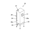
貯留タンク10は、図1及び図2に示すように、液体貯留用のタンク本体20と、タンク本体20の頂部に設けられ、配送用車両4から液体の補給(注入)を受ける液体注入口21と、タンク本体20に貯留された液体を外部に取り出す液体取出し口22と、タンク本体20内に収容された残量情報検出部(不図示)と、タンク本体20の一側面20aに取り付けられた送信部11と、タンク本体20を支持する、金属製や樹脂製のタンク支持部23と、を備え、配送先2に設置される。
As shown in FIGS. 1 and 2, the
タンク本体20は、本実施形態ではほぼ縦長直方体状の形状を有しているが、これに限定されず、ほぼ立方形、ほぼ横長直方体、ほぼ球、ほぼ円柱、ほぼ多角柱などの種々の形状に形成できる。また、タンク本体20の容量は、全ての配送先2において一律の容量としてもよいが、配送先2での液体の日常的な消費量や貯留タンク10を設置するスペースの面積などに応じて適宜選択してもよい。
In this embodiment, the tank
本発明の液体配送システム1では貯留タンク10内の液体の残量が所定の基準量よりも少なくなった時点で液体が新たに補給されるので、従来のドラム缶よりも貯留タンク10(タンク本体20)の容量を小さくすることができ、省スペースや洗浄の容易さなどの観点から好ましい。タンク本体20を小さくすることにより、液体が可燃性物質である場合は、配送先2に貯留保存される液体量も少なくなるので、万一火災などの災害が発生した場合でも、配送先2の周囲の環境への危険性を、容量200リットルのドラム缶を用いる場合よりも低減できる。タンク本体20の材質は特に限定されず、例えば、金属、合成樹脂、繊維強化合成樹脂等を使用できる。本実施形態では、タンク本体20とタンク支持部23とが分離した形態のものを用いているが、これに限定されず、これらが一体化されたものを用いることもできる。
In the liquid delivery system 1 of the present invention, the liquid is newly replenished when the remaining amount of the liquid in the
液体注入口21はネジ蓋により、また、液体取出し口22はコック(不図示)により、それぞれ開閉自在に構成されている。液体注入口21及び液体取出し口22の開閉機構としては、ネジ蓋やコックに限定されず、一般的な開閉機構を特に限定なく採用できる。
The
また、タンク本体20の液体取り出し口22が設けられた側の側面20xには、側面20xの上下方向の一端辺に沿って、上下方向に延び、ガラスや透明性樹脂からなる板が嵌めこまれた目視窓24が設けられている。配送先2の作業者は目視窓24により、液体の消費の概況を検知することができる。
Further, a plate made of glass or a transparent resin, which extends in the up-down direction along one vertical side of the
残量情報検出部と送信部11とは電気的に結線されている。残量情報検出部は、貯留タンク10(タンク本体20)の内部に設けられ、所定の時間毎に残量情報(タンク本体20内部の液体の残量)を検出し、送信部11に出力する。残量情報検出部には、例えば、液面変位センサ、液面レベルセンサ、液量センサなどの各種センサを使用できる。送信部11は残量情報検出部から入力された残量情報を配送元3の受信部に送信する。本実施形態の送信部11は、上述の電気通信手段に対応した通信インターフェース回路である。なお、送信部11としては、例えば、電気通信回路を利用する通信用端末装置を用いてもよい。通信用端末装置には、例えば、コンピュータ、ワークステーション、スマートフォン端末、タブレット型端末、携帯電話端末などを使用できる。
The remaining amount information detection unit and the
別形態の送信部11は、例えば、CPU(中央演算装置)、メモリ、タイマなどからなる残量情報検出用電子回路と通信用端末装置とから構成される。本実施形態では、CPUが残量情報検出部による所定時間毎の残量情報の検出を制御し、得られた残量情報を一旦メモリに書き込んだ後、通信用端末装置を経由して受信部に向けて送信する。なお、コンピュータ、ワークステーション、スマートフォン端末、タブレット型端末などの通信用端末を用いる場合は、これらが内蔵する電子回路を、残量情報検出用電子回路として使用することもできる。また、送信部11のCPUが残量と基準量とを比較し、残量が基準量以下であった場合に、残量が基準量以下であることを示す情報を残量情報として配送元3に送信するように設定することもできる。
The
また、タンク本体20に残量警告手段(不図示)を設け、残量が所定量(判定の基準量よりも多い量)に達した時点で、配送先2の作業員などに液体の給液時期が近付いていることを知らせるように設定することもできる。残量警告手段には、例えば、ランプ、アナログメータ、デジタルメータ、ブザーなどを使用できる。
Further, a remaining amount warning means (not shown) is provided in the
より具体的には、残量情報検出用電子回路又は通信手段に内蔵される電子回路のメモリに、前回の液体補給日時、前回の液体補給日時からの経過日時、当該配送先2における一日当たりの標準的な液体消費量などの情報を予め入力しておく。そして、電子回路中のCPUは、前記情報、及び残量情報に基づいて次回の液体補給が必要になるまでの日時を演算し、その演算結果に基づいて次回の液体補給までの日時が例えば2日以内であるか又は2日を超えるかを判定し、2日以内であるとの判定結果に基づいて、CPUから残量警告手段に制御信号を送り、ランプ、メータなどは異色点滅させ、またブザーなどは警告音がなるように制御し、配送先2の作業者などに給液時期が迫っていることを知らせることもできる。また、残量情報に基づいて、所定量を下回った場合に、例えば、異色点滅したり、警告音を発したりするように設定することもできる。また、給油時期が迫っていることを示す情報を残量情報の一部として配送元3に送信するように設定することもできる。
More specifically, the last liquid supply date and time, the date and time elapsed since the last liquid supply date and time, and the Information such as standard liquid consumption is input in advance. Then, the CPU in the electronic circuit calculates the date and time until the next liquid replenishment is necessary based on the information and the remaining amount information, and based on the calculation result, the date and time until the next liquid replenishment is, for example, 2 It is determined whether it is within two days or more than two days, and based on the determination result that it is within two days, a control signal is sent from the CPU to the remaining amount warning means, and the lamp, the meter, etc., flash different colors, A buzzer or the like can be controlled to emit a warning sound to notify the worker at the
次に、配送元3に設置されているコンピュータ12について説明する。コンピュータ12には、上述の電気通信手段に対応する通信インターフェース回路(不図示)が接続されている。本実施形態では、コンピュータ12、より具体的にはコンピュータ12に内蔵されたCPU、メモリ、タイマなどを含む電気回路が判定部、及び配送指示部を兼ね、また、通信インターフェース回路が受信部となる。
Next, the
メモリには電気通信回路を通じて残量情報や配送用車両4の現在位置情報などが入力されている。また、メモリには、例えば、残量情報を判定するための基準量(数値)、各配送先2に設置された貯留タンク10(タンク本体20)の容量、各配送先2で使用される液体の種類、各配送先2での液体の標準消費量、各配送先2での液体の前回補給日時や補給量、各配送先2の住所、残量情報と基準量とを比較し、残量情報を判定するためのプログラム、残量情報と配送先2での液体の標準消費量とから当該配送先2において液体が無くなるまでの予測時間を算出するプログラムなどが予め入力されている。基準量は配送先2に関係なく一律でもよいが、配送先2毎の液体消費量などに応じて基準量を設定することが好ましい。配送先2での液体の標準消費量とは、例えば、配送先2における所定期間内の液体の合計消費量を前記所定期間の日数で除した値である。
In the memory, remaining amount information, current position information of the delivery vehicle 4, and the like are input through an electric communication circuit. In the memory, for example, a reference amount (numerical value) for determining remaining amount information, the capacity of the storage tank 10 (tank body 20) installed at each
CPUは、本実施形態では判定部、及び配送指示部として機能する。より具体的には、CPUは、メモリから残量情報及び基準量を取り出して比較し、残量情報が基準量以下であるか否かを判定する。CPUは、残量情報が基準量以下であると判定した場合には、電気通信回路を通じて、液体補給が必要な配送先2の名称、その住所などを含む指示情報を配送用車両4に送信し、配送用車両4を配送先2に配車する。また、CPUは指示情報をコンピュータ12の画面に表示し、配送元3に待機する配送用車両4の運転手兼配送要員が指示情報が表示された画面を確認し、自身で配送用車両4を配送先2に配車するように設定することもできる。なお、上述したように、送信部11が、残量が基準値以下であることを示す残量情報を送信する場合、コンピュータ12(CPU)はその残量情報を受信した時に貯留タンク10内の残量が基準値以下であると判定し、指示情報を送信又は画面に表示してもよい。
The CPU functions as a determination unit and a delivery instruction unit in the present embodiment. More specifically, the CPU takes out the remaining amount information and the reference amount from the memory, compares them, and determines whether the remaining amount information is equal to or less than the reference amount. If the CPU determines that the remaining amount information is equal to or less than the reference amount, the CPU transmits instruction information including the name, address, and the like of the
また、CPUが、残量情報が基準量以下であると判定した場合に、残量情報、及び当該配送先2における貯留タンク10(タンク本体20)の容量などから液体補給量の概算量を算出し、残量情報、及び配送先2での液体の標準消費量などから当該配送先2で液体が無くなるまでの予想時間を算出し、これらの算出結果を指示情報に含めて配送用車両4に送信するように設定することもできる。前記の算出を実行するためのプログラムは予めメモリに入力されている。
When the CPU determines that the remaining amount information is equal to or less than the reference amount, the CPU calculates an approximate amount of the liquid supply amount from the remaining amount information and the capacity of the storage tank 10 (tank main body 20) at the
液体補給が必要な配送先2が複数ある場合は、CPUが、各配送先2において液体が無くなるまでの予想時間、各配送先2の住所、配送用車両4の現在位置などから、配送先2への配車優先順位及び配車ルートを決定し、配車ルートを含めた指示情報を配送用車両4に送信するように設定することもできる。また、複数の配送用車両4が走行中である場合は、CPUが、配送先2の住所、各配送用車両4の現在位置情報などから、配送先2に最も近い地点を走行する配送用車両4に指示情報を送信するように設定することもできる。
When there are a plurality of
本実施形態の液体配送システム1では、前述のように、例えば1リットル単位で液体を補給することができる。すなわち、本実施形態では、貯留タンク10が満充填になる量又は満充填にならない量の液体を補給することができる。この点を利用して、例えば、判定部がメモリに予め入力された配送先情報に基づいて次のような判定を実行するように設定することもできる。配送先情報とは、例えば、配送先2の住所、配送先2毎の残量情報、配送先2毎の貯留タンク10(タンク本体20)のタンク容量、配送先2毎の液体消費履歴などである。液体消費履歴とは、例えば、当該配送先2の過去の液体消費量を月別にデータテーブル化したものである。
In the liquid delivery system 1 of the present embodiment, as described above, the liquid can be supplied, for example, in units of 1 liter. That is, in the present embodiment, it is possible to replenish the
判定部は、まず、配送先情報に基づいて複数の配送先2を含むグループを設定し、グループ内の配送先2毎の液体消費履歴から、配送先2毎に液体標準消費量を決定する。グループは、例えば、配送先2の住所に基づいて近隣に所在する配送先2を含むように設定することもでき、同様の液体消費履歴を有する複数の配送先2を含むように設定することもできる。また、液体標準消費量とは、例えば、液体消費履歴における配送月と同じ月の液体消費量を日割り計算したものである。次に、判定部は、配送先2毎の残量情報、タンク容量、及び液体標準消費量に基づいて、次回の補給時期がグループ内の全ての配送先2においてほぼ同時期になるように、配送先2毎に固有の液体補給基準量を決定する。ここで、ほぼ同時期とは、グループ内のエリア面積などにより異なるが、例えば、1〜2日の範囲である。
The determination unit first sets a group including a plurality of
液体補給基準量は、配送先2の液体消費量がほぼ一定である場合はそのまま実際の補給量とすることができ、配送先2が液体を不規則に大量消費することがある場合や配送先2の液体消費量が増加傾向にある場合には、液体補給基準量に補正量を加算し、実際の補給量とすることが好ましい。配送先2の不規則な液体の大量消費は液体消費履歴の一部としてメモリに入力される。また、液体消費量が増加傾向にある場合とは、例えば、配送月の前3カ月の液体消費量が前年同月に比べて5〜10%又はそれ以上増加している場合や、配送月の前6カ月にわたって液体消費量が連続的に増加している場合などである。補正量は配送先2に応じて異なるが、例えば、1〜50リットル程度の範囲から適宜選択すればよい。なお、液体補給基準量は一定の値とするのではなく、補給機会毎にCPUが上述の配送先情報に基づいて改めて算出することが好ましい。
The liquid replenishment reference amount can be the actual replenishment amount as long as the liquid consumption amount of the
配送指示部は、判定部で設定された液体基準補給量を含めた指示情報を配送用車両4に報知するか又はコンピュータ12の画面に表示することにより報知し、それに基づいて配送用車両4は、当該グループの配送先2に対してルート配送を行ない、液体補給基準量の液体を各配送先2の貯留タンク10に注入する。液体補給基準量は全ての配送先2の貯留タンク10を満充填する量とは限られないので、配送先2のタンク容量や液体標準消費量などによって、満充填になったりならなかったりする場合が生じ得る。
このような設定により、配送用車両4のルート配送の高効率化を図ることができる。
The delivery instruction unit notifies the delivery vehicle 4 of the instruction information including the liquid reference supply amount set by the determination unit or displays the information on the screen of the
With such a setting, the efficiency of route delivery of the delivery vehicle 4 can be improved.
本実施形態では、受信部、判定部、及び配送指示部として、コンピュータ12とそれに接続された通信インターフェース回路を用いているが、これに限定されず、配送先2の送信部11と同様に、CPU、メモリ、タイマなどから構成された電子回路を内蔵する、ワークステーション、スマートフォン端末、タブレット型端末などの通信用端末をコンピュータ12に代えて用いても良い。また、本実施形態では、受信部、判定部、及び配送指示部を配送元3に設けているが、これに限定されず、例えば、配送用車両4内にこれらの各部を含む電子回路や該電子回路を内蔵する通信用端末装置などを設けることもできる。
In the present embodiment, the
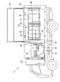
次に、主に図3及び図4に基づいて、配送用車両4について説明する。本実施形態の配送用車両4はトラックであり、その荷台4aにはアルミニウム合金などからなる金属製荷箱25(以下単に「荷箱25」とすることがある)が取り付けられ、荷箱25の内部に、配送用車両4の進行方向後方から順番に、貯留タンク10(タンク本体20)よりも容量の大きい配送用タンク13と、貯留タンク10に液体を注入するホース14と、配送用タンク13内の液体をホース14に送給するポンプ15とが収載されている。
Next, the delivery vehicle 4 will be described mainly with reference to FIGS. The delivery vehicle 4 of the present embodiment is a truck, and a
荷箱25の長手方向の所定位置には、荷箱25の強度を高め、急ブレーキ操作時などに荷箱25内に収載される各部材の急激な移動による破損などを防止するために、荷箱25の底面から内壁天井まで延びるように隔壁26が立設されている。本実施形態では、荷箱25内の隔壁26で仕切られた配送用車両4の進行方向後方側空間に配送用タンク13が収載され、配送用車両4の進行方向前方側空間にホース14及びポンプ15が収載されている。また、荷箱25の長手方向の一側面はほぼ全面が開口可能になっており、この開口を塞ぐために、進行方向後方側空間の開口には上下方向に開閉自在な第1扉27が設けられ、進行方向前方側空間の開口には水平方向に開閉自在な第2扉28が設けられている。第1、第2扉27、28はそれぞれ独立に開閉できる。また、第1、第2扉27、28は、配送用車両4の走行時には閉じられ、配送先2での液体の補給時に開かれる。
At a predetermined position in the longitudinal direction of the
配送用タンク13は、配送用車両4の進行方向に2つ並べて配置され、それぞれ、貯留タンク10よりも容量の大きいタンク本体30と、タンク本体30を収納して支持する金属製枠体31と、を含む。タンク本体30の頂部には液体の補給を受けるか又は液体をポンプ15に向けて排出するための開閉自在な給排口32が、また、タンク本体30の一側面の下部には液体をポンプ15に向けて排出するか又は配送用タンク13の洗浄時に廃液を排出するための開閉自在な排出口33がそれぞれ設けられている。本実施形態では、排出口33とポンプ15の液体受入口(不図示)とは、隔壁26を貫通するホース29により連結されているが、これに限定されず、給排口32とポンプ15の液体受入口とをホース29で連結してもよい。本実施形態では2個の配送用タンク13が用いられているが、配送用タンク13の容量に応じて任意の個数とすることができる。
The two
本実施形態では、ホース14とポンプ15とが一体化された注入装置を用いる。ホース14は、一端がポンプ15の液体排出口(不図示)に接続され、遊離端となる他端に液体計量ノズル34が装着されている。液体計量ノズル34は、液体の貯留タンク10への補給(注入)時に開口された液体注入口21に挿入される。これにより、所定量の液体を貯留タンク10に補給できる。これはガソリンスタンドなどにおける液体計量ノズルと同様のシステムである。また、貯留タンク10内に設けられた残量情報検出部を利用して補給終了のタイミングを測っても良い。ホース14は、ポンプ15のホース収納空間35内に巻き取られた状態で収納され、液体補給時に必要な長さだけを取り出して用いられる。
In the present embodiment, an injection device in which the
配送用タンク13の給排口32又は排出口33、及び貯留タンク10の液体注入口21を開け、ホース14の液体計量ノズル34を液体注入口21に挿入し、ポンプ15を作動させることによって、配送用タンク13内の液体の所定量が貯留タンク10内に補給(注入)される。補給終了のタイミングは、前述のように自動的に決定してもよく、また、満充填する場合には液体があふれることがないように手動で調整することもできる。なお、本実施形態では、ホース14とポンプ15とが一体化された注入装置を用いているが、これに限定されず、ホース14とポンプ15とが分離したものを用いることもできる。
By opening the supply /
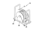
図5は、別形態のホース16の構成を模式的に示す斜視図である。ホース16は、一端に配送用タンク13の給排口32又は排出口33に嵌合可能な金具36が装着され、他端に開閉自在な液体計量ノズル37が装着されたものであり、ホース巻き取り台38に巻き取られている。ホース16は、ホース巻き取り台38の下面に取り付けられた複数の滑車39により移動可能になっている。ホース16は、ホース14とポンプ15とが一体化された注入装置と比べると、配送用車両4が貯留タンク10の近くまで入り込めない場合などに有利である。
FIG. 5 is a perspective view schematically illustrating a configuration of a
配送用車両4は、その位置情報を配送元3のコンピュータ12などに送信するために、GPS端末、GPS端末付の携帯通信端末、カーナビゲーションシステム(いずれも不図示)などを装備していることが好ましい。また、本実施形態の配送用車両4はトラックであるが、これに限定されず、ワゴン車などを用いることもできる。
The delivery vehicle 4 is equipped with a GPS terminal, a portable communication terminal with a GPS terminal, a car navigation system (all not shown), etc., for transmitting the position information to the
本発明の液体配送システムによれば、配送先2に設置される貯留タンク10内に設けられた残量情報検出手段により検出された液体の残量情報を、送信部11から配送元3又は配送用車両4に設けられた受信部に送信し、その残量情報に基づいて判定が実施され、残量情報が基準量以下であると判定された場合には、配送先2に配送用車両4を配車する指示情報が配送用車両4に報知され又は配送先2に待機する作業員に指示情報が画面表示などにより報知され、それに基づいて配送用車両4が配送先2に赴いて、液体を補給する。これにより、非常に効率的で、作業者や自然環境に負担を与えない液体の補給が可能になる。
According to the liquid delivery system of the present invention, the remaining amount information of the liquid detected by the remaining amount information detecting means provided in the
以上、本発明の実施形態について説明したが、本発明はこうした実施例に何ら限定されるものではなく、本発明の要旨を逸脱しない範囲において種々なる形態で実施し得ることは勿論である。 As described above, the embodiments of the present invention have been described, but the present invention is not limited to these embodiments at all, and it goes without saying that the present invention can be implemented in various forms without departing from the gist of the present invention.
1 液体配送システム
2 配送先
3 配送元
4 配送用車両
4a 配送用車両の荷台
10 貯留タンク
11 送信部
12 コンピュータ
13 配送用タンク
14、16、29 ホース
15 ポンプ
20 タンク本体
20a、20x タンク本体の一側面
21 液体注入口
22 液体取り出し口
23 タンク支持部
24 目視窓
25 金属製荷箱
26 隔壁
27 第1扉
28 第2扉
30 タンク本体
31 金属製枠体
32 給排口
33 排出口
34、37 液体計量ノズル
35 ホース収納空間
36 金具
38 ホース巻き取り台
39 滑車
REFERENCE SIGNS LIST 1
Claims (5)
前記液体配送システムに含まれるコンピュータが、
前記貯留タンクに設置され前記貯留タンク内の前記液体の残量を検出する残量情報検出部から送信された残量情報を受信する受信部と、
前記受信部によって受信された前記残量情報に基づいて、前記貯留タンク内の前記液体の残量が所定の基準量以下であるか否かを判定する判定部と、
前記配送用車両に指示情報を報知する配送指示部と、を含み、
前記判定部において、同様の液体消費履歴を有する複数の配送先を含むグループが設定され、
前記判定部は、前記グループ内の前記配送先毎の前記残量情報、前記配送先毎に設置された前記貯留タンク容量、及び、前記配送先毎の前記液体消費履歴から算出される液体標準消費量に基づいて、
前記グループ内の配送先に対して、次回液体補給時期が同時期に液体を補給できるように、前記配送先毎に固有の液体補給基準量を決定し、
前記判定部が、前記グループ内の全ての前記配送先の前記残量が前記基準量以下であると判定した場合、前記配送指示部が前記配送用車両に対して、前記グループ内の全ての前記配送先に液体を1回の配送で配送するように指示情報を報知する液体配送システム。 A liquid delivery system for delivering and supplying liquid to a storage tank installed at a delivery destination by a delivery vehicle,
A computer included in the liquid delivery system,
A receiving unit that receives the remaining amount information transmitted from the remaining amount information detecting unit installed in the storage tank and detecting the remaining amount of the liquid in the storage tank,
Based on the remaining amount information received by the receiving unit, a determination unit that determines whether the remaining amount of the liquid in the storage tank is equal to or less than a predetermined reference amount,
A delivery instruction unit that notifies instruction information to the delivery vehicle,
In the determination unit, a group including a plurality of delivery destinations having the same liquid consumption history is set,
The determination unit is configured to calculate the remaining amount information for each delivery destination in the group, the capacity of the storage tank installed for each delivery destination, and the liquid standard consumption calculated from the liquid consumption history for each delivery destination. Based on the quantity
For the delivery destinations in the group, a liquid supply reference amount unique to each delivery destination is determined so that the next liquid supply time can supply the liquid at the same time,
When the determination unit determines that the remaining amount of all the delivery destinations in the group is equal to or less than the reference amount, the delivery instruction unit determines the delivery vehicles, and A liquid delivery system that reports instruction information to deliver a liquid to a delivery destination in one delivery.
前記配送用車両から液体の補給を受ける液体注入口と、
貯留された液体を外部に取り出す液体取出し口と、
貯留されている前記液体の残量を検出する残量情報検出部と、
前記残量情報検出部によって検出された残量に関する残量情報を、配送元のコンピュータに送信する送信部と、を含む請求項1乃至請求項4のいずれかに記載の液体配送システム。
The storage tank is
A liquid inlet for receiving supply of liquid from the delivery vehicle,
A liquid outlet for taking out the stored liquid to the outside,
A remaining amount information detecting unit for detecting the remaining amount of the stored liquid,
Liquid delivery system according to any one of claims 1 to 4 including a transmission section for transmitting a remaining amount information about the remaining amount detected by the remaining amount information detecting unit, the delivery source computer.
Priority Applications (2)
| Application Number | Priority Date | Filing Date | Title |
|---|---|---|---|
| JP2015085611A JP6666074B2 (en) | 2015-04-20 | 2015-04-20 | Liquid delivery system |
| JP2019011809A JP6928624B2 (en) | 2015-04-20 | 2019-01-28 | Liquid delivery system |
Applications Claiming Priority (1)
| Application Number | Priority Date | Filing Date | Title |
|---|---|---|---|
| JP2015085611A JP6666074B2 (en) | 2015-04-20 | 2015-04-20 | Liquid delivery system |
Related Child Applications (1)
| Application Number | Title | Priority Date | Filing Date |
|---|---|---|---|
| JP2019011809A Division JP6928624B2 (en) | 2015-04-20 | 2019-01-28 | Liquid delivery system |
Publications (3)
| Publication Number | Publication Date |
|---|---|
| JP2016204088A JP2016204088A (en) | 2016-12-08 |
| JP2016204088A5 JP2016204088A5 (en) | 2018-04-12 |
| JP6666074B2 true JP6666074B2 (en) | 2020-03-13 |
Family
ID=57486650
Family Applications (1)
| Application Number | Title | Priority Date | Filing Date |
|---|---|---|---|
| JP2015085611A Active JP6666074B2 (en) | 2015-04-20 | 2015-04-20 | Liquid delivery system |
Country Status (1)
| Country | Link |
|---|---|
| JP (1) | JP6666074B2 (en) |
Families Citing this family (2)
| Publication number | Priority date | Publication date | Assignee | Title |
|---|---|---|---|---|
| JP7027833B2 (en) * | 2017-11-17 | 2022-03-02 | トヨタ自動車株式会社 | Information processing equipment, information processing method, information processing program |
| JP7245665B2 (en) * | 2019-02-04 | 2023-03-24 | コスモ石油ルブリカンツ株式会社 | Lubricant sales system |
Family Cites Families (3)
| Publication number | Priority date | Publication date | Assignee | Title |
|---|---|---|---|---|
| JP2004362070A (en) * | 2003-06-02 | 2004-12-24 | Idemitsu Kosan Co Ltd | Automatic ordering/delivery system for cogeneration grid fuel |
| JP2005280962A (en) * | 2004-03-30 | 2005-10-13 | Tokiko Techno Kk | Fluid cargo handling and distribution system |
| JP5509184B2 (en) * | 2011-12-05 | 2014-06-04 | 株式会社日立情報制御ソリューションズ | Fuel tank fuel replenishment determination device |
-
2015
- 2015-04-20 JP JP2015085611A patent/JP6666074B2/en active Active
Also Published As
| Publication number | Publication date |
|---|---|
| JP2016204088A (en) | 2016-12-08 |
Similar Documents
| Publication | Publication Date | Title |
|---|---|---|
| JP6666074B2 (en) | Liquid delivery system | |
| KR101207338B1 (en) | User terminal, system and method for supplying information in oiling | |
| CA2895672A1 (en) | System and method for dispensing and sale of bulk products | |
| CZ14789U1 (en) | Mobile gasoline filling station | |
| JP6928624B2 (en) | Liquid delivery system | |
| JP2016179677A5 (en) | ||
| JP7449641B2 (en) | Hydrogen gas distribution system | |
| US20060131078A1 (en) | Mobile chemical preparation plant and method of managing a chemical inventory thereon | |
| ES2915419T3 (en) | System for distributing laundry treatment substances in a washing machine equipped with an automatic dosing device | |
| ITMI950181A1 (en) | AUTOMATIC FILLER TO RE-FILL BOTTLES AND SIMILAR | |
| JP5509184B2 (en) | Fuel tank fuel replenishment determination device | |
| EA011185B1 (en) | Transferable liquid dispensing station | |
| JP2001307279A (en) | System for commodity distribution | |
| US20020130142A1 (en) | Windshield washer fluid dispenser | |
| US9440842B1 (en) | Cleaning product dispensing system | |
| US20220165114A1 (en) | System and method for the supply and/or acquisition of bulk products | |
| JP2019200636A (en) | System for managing remaining amount of gas in gas cylinder | |
| JP6791781B2 (en) | Fuel supply system | |
| US10149576B1 (en) | Automatic liquid soap supplying system | |
| US10012526B2 (en) | Windshield washer fluid vending system with portable excess fluid containers | |
| JP2016204088A5 (en) | ||
| US10346791B2 (en) | Automated additive inventory and delivery logistics control system and method thereof | |
| WO2022182218A1 (en) | System, method and components to replenish consumer goods in reusable packaging | |
| CN113276564B (en) | Ink replenishing system and method and ink management system | |
| CN215551944U (en) | Ink replenishing system |
Legal Events
| Date | Code | Title | Description |
|---|---|---|---|
| RD02 | Notification of acceptance of power of attorney |
Free format text: JAPANESE INTERMEDIATE CODE: A7422 Effective date: 20170606 |
|
| A521 | Request for written amendment filed |
Free format text: JAPANESE INTERMEDIATE CODE: A523 Effective date: 20180305 |
|
| A621 | Written request for application examination |
Free format text: JAPANESE INTERMEDIATE CODE: A621 Effective date: 20180305 |
|
| A871 | Explanation of circumstances concerning accelerated examination |
Free format text: JAPANESE INTERMEDIATE CODE: A871 Effective date: 20180313 |
|
| A975 | Report on accelerated examination |
Free format text: JAPANESE INTERMEDIATE CODE: A971005 Effective date: 20180419 |
|
| A131 | Notification of reasons for refusal |
Free format text: JAPANESE INTERMEDIATE CODE: A131 Effective date: 20180426 |
|
| A521 | Request for written amendment filed |
Free format text: JAPANESE INTERMEDIATE CODE: A523 Effective date: 20180625 |
|
| A131 | Notification of reasons for refusal |
Free format text: JAPANESE INTERMEDIATE CODE: A131 Effective date: 20180704 |
|
| A521 | Request for written amendment filed |
Free format text: JAPANESE INTERMEDIATE CODE: A523 Effective date: 20180817 |
|
| A02 | Decision of refusal |
Free format text: JAPANESE INTERMEDIATE CODE: A02 Effective date: 20181115 |
|
| A521 | Request for written amendment filed |
Free format text: JAPANESE INTERMEDIATE CODE: A523 Effective date: 20190128 |
|
| C60 | Trial request (containing other claim documents, opposition documents) |
Free format text: JAPANESE INTERMEDIATE CODE: C60 Effective date: 20190128 |
|
| A911 | Transfer to examiner for re-examination before appeal (zenchi) |
Free format text: JAPANESE INTERMEDIATE CODE: A911 Effective date: 20190201 |
|
| C21 | Notice of transfer of a case for reconsideration by examiners before appeal proceedings |
Free format text: JAPANESE INTERMEDIATE CODE: C21 Effective date: 20190207 |
|
| A912 | Re-examination (zenchi) completed and case transferred to appeal board |
Free format text: JAPANESE INTERMEDIATE CODE: A912 Effective date: 20190222 |
|
| C211 | Notice of termination of reconsideration by examiners before appeal proceedings |
Free format text: JAPANESE INTERMEDIATE CODE: C211 Effective date: 20190301 |
|
| C22 | Notice of designation (change) of administrative judge |
Free format text: JAPANESE INTERMEDIATE CODE: C22 Effective date: 20190809 |
|
| C13 | Notice of reasons for refusal |
Free format text: JAPANESE INTERMEDIATE CODE: C13 Effective date: 20191101 |
|
| A521 | Request for written amendment filed |
Free format text: JAPANESE INTERMEDIATE CODE: A523 Effective date: 20191113 |
|
| C23 | Notice of termination of proceedings |
Free format text: JAPANESE INTERMEDIATE CODE: C23 Effective date: 20200123 |
|
| C03 | Trial/appeal decision taken |
Free format text: JAPANESE INTERMEDIATE CODE: C03 Effective date: 20200220 |
|
| C30A | Notification sent |
Free format text: JAPANESE INTERMEDIATE CODE: C3012 Effective date: 20200220 |
|
| A61 | First payment of annual fees (during grant procedure) |
Free format text: JAPANESE INTERMEDIATE CODE: A61 Effective date: 20200220 |
|
| R150 | Certificate of patent or registration of utility model |
Ref document number: 6666074 Country of ref document: JP Free format text: JAPANESE INTERMEDIATE CODE: R150 |
|
| R250 | Receipt of annual fees |
Free format text: JAPANESE INTERMEDIATE CODE: R250 |