JP6666024B2 - Imaging device and external operation device for operating the same - Google Patents
Imaging device and external operation device for operating the same Download PDFInfo
- Publication number
- JP6666024B2 JP6666024B2 JP2015139350A JP2015139350A JP6666024B2 JP 6666024 B2 JP6666024 B2 JP 6666024B2 JP 2015139350 A JP2015139350 A JP 2015139350A JP 2015139350 A JP2015139350 A JP 2015139350A JP 6666024 B2 JP6666024 B2 JP 6666024B2
- Authority
- JP
- Japan
- Prior art keywords
- imaging
- unit
- recording
- related information
- video signal
- Prior art date
- Legal status (The legal status is an assumption and is not a legal conclusion. Google has not performed a legal analysis and makes no representation as to the accuracy of the status listed.)
- Active
Links
Images


Landscapes
- Television Signal Processing For Recording (AREA)
- Studio Devices (AREA)
Description
本発明は、撮像装置に外部記憶装置が接続されたシステムにおいて、オンスクリーン中に誤ってオンスクリーン映像を録画してしまうことを防止するための撮像装置及びそれを操作する外部操作器に関するものである。 The present invention relates to an imaging device for preventing an on-screen video from being erroneously recorded during on-screen in a system in which an external storage device is connected to the imaging device, and an external operation device for operating the imaging device. is there.
一般にテレビ放送局で使用されているテレビカメラは、映像出力のインタフェースとして、SMPTE(全米映画テレビジョン技術者協会)、ARIB(一般社団法人電波産業会)で規定されているSDI(シリアルデジタルインターフェース)を採用したカメラが多い。 Generally, a television camera used in a television broadcasting station has an SDI (Serial Digital Interface) defined by SMPTE (American Association of Motion Picture and Television Engineers) and ARIB (General Incorporated Association of Radio Industries and Businesses) as an interface for video output. Many cameras have adopted.
特許文献1には、SDI出力のテレビカメラと映像記録装置を接続して、SDIの補助データパケットに映像記録装置を制御する制御信号を重畳して、映像記録装置を制御することが開示されている。
特許文献1では、テレビカメラ本体の録画開始の操作スイッチを押下すると、SDIの補助データパケットに映像記録装置の録画を開始する制御信号を重畳して出力する。映像記録装置では、補助データパケットから録画を開始する制御信号を検出し録画を開始する。しかし、テレビカメラが、撮像映像にテレビカメラの操作機能を表示するオンスクリーン表示を行っている場合、誤って録画開始のスイッチが押下されると、オンスクリーン映像が映像記録装置に録画されてしまう。
In
本発明の目的は、上述の問題点を解消し、オンスクリーン表示中の映像を誤って録画してしまうことを防止する撮像装置を提供することにある。 An object of the present invention is to provide an imaging apparatus that solves the above-described problems and prevents an image being displayed on-screen from being erroneously recorded.
上記目的を達成するための本発明に係る撮像装置は、撮像部と、撮像関連情報を生成する生成部と、前記撮像部によって取得された映像信号に前記撮像関連情報を重畳することが可能な映像処理部と、前記撮像関連情報が重畳されている前記映像信号または前記撮像関連情報が重畳されていない前記映像信号を録画機器へ出力する出力部と、を備える撮像装置であって、前記録画機器での録画開始指令が指令入力手段から入力された場合、前記撮像関連情報の内容に基づいて前記映像処理部による前記重畳を継続または中止した後に、前記録画開始指令を前記録画機器へ出力する、ことを特徴とする。
Imaging device according to the present invention for achieving the above object, an imaging unit, a generation unit for generating an image related information, capable of superimposing the imaging-related information to the video signal acquired by the imaging unit an imaging device comprising an image processing unit, pre-SL and an output section you output the video signal the video signal or the imaging-related information is not superimposed imaging-related information is superimposed to the recording device, and before if recording start command with the recording image device is inputted from the command input means, said imaging after continue or discontinue the superimposed by the image processing unit based on the contents of the related information, wherein the recording start command recording device Output to the
本発明に係る撮像装置は、オンスクリーン表示中に、誤ってオンスクリーン映像を録画してしまうことを防止する撮像装置を提供することができる。 The imaging apparatus according to the present invention can provide an imaging apparatus that prevents an on-screen video from being erroneously recorded during on-screen display.
本発明を図示の実施例に基づいて詳細に説明する。 The present invention will be described in detail based on the illustrated embodiment.
図1は、本発明の実施例1に係る撮像装置100の構成図である。
FIG. 1 is a configuration diagram of an
撮像装置100は、撮像部101、映像信号処理部102(映像処理部)、CPU103、オンスクリーン生成部104、映像信号1出力部105、映像信号2出力部106、通信部107(指令入力手段)、操作部108(指令入力手段)から構成されている。また、撮像装置100は、遠隔で撮像装置100の操作を行うための外部操作器200が通信部107と所定のケーブルで通信可能に接続されている。更に撮像装置100から出力される映像信号を録画するための外部録画機器300が映像信号1出力部105に同軸ケーブルで接続され、映像信号をモニタ表示する表示器400が映像信号2出力部106に同軸ケーブルで接続されている。本実施例では、映像信号出力部が2系統構成されているが、1系統、または、3系統以上の複数で構成されていても構わない。
The
本発明の撮像装置100と外部操作器200、又は、それに加えて、外部録画機器300及び表示器400を含む構成を、本発明の撮像装置100の効果を享受する撮像システムとしてもよい。
A configuration that includes the
撮像部101は、レンズ(不図示)からの光学像をCCDやCMOSセンサー等の撮像素子(不図示)を介して光電変換し、アナログ信号として出力する。
The
映像信号処理部102は、撮像部101からのアナログ信号をデジタル変換し、ゲイン、輝度、色等の所定の画像処理をCPU103(制御部)からの指令信号に応じて調整しデジタル映像信号として映像信号1出力部105、映像信号2出力部106へ出力する。また、映像信号処理部102は、撮像映像に撮像装置の操作機能(撮像関連情報)を表示するオンスクリーン表示のためのオンスクリーン情報(以後、OSD情報とも記載する)を後述するオンスクリーン生成部104から受信する。そして、撮像映像とともに撮像装置100の操作機能を表示する文字や記号、アイコン等を撮像部101からの映像信号と合成(重畳)する。
The video
映像信号1出力部105、映像信号2出力部106は、映像信号処理部102からのデジタル映像信号を、HD−SDI、3G−SDI信号等のシリアルデジタル信号に変換して出力する。HD−SDI、3G−SDI信号は、SMPTE(全米映画テレビジョン技術者協会)、ARIB(登録商標)(一般社団法人電波産業会)で規定されているSDI(シリアルデジタルインターフェース)規格である。
The
CPU103は、撮像部101、映像信号処理部102、オンスクリーン生成部104、映像信号1出力部105、映像信号2出力部106、通信部107、操作部108と各々接続され、各部の設定や制御を行っている。
The
オンスクリーン生成部104は、操作部108、または、外部操作器200で所定のスイッチ(不図示)を押下すると、CPU103の制御に基づき、撮像装置100の操作機能を表示する文字や記号、アイコン等のOSD情報を生成する。具体的には、文字、記号、アイコン等のビットマップデータ及びオンスクリーン表示する画面上の表示位置座標データが所定のフォーマットで映像信号処理部102へ送信(入力)される。
When a predetermined switch (not shown) is pressed on the
通信部107は、外部操作器200で撮像装置100のゲインやシャッター等を操作する指令信号(コマンド)をRS−232CやRS−422等の所定のファーマットで送受信するためのインタフェースである。また、外部操作器200からの指令信号をCPU103と所定のフォーマットで送受信している。
The
操作部108は、撮像装置100の操作を行うためのキースイッチや、タッチパネル等である。
The
次に、外部録画機器300がどのように録画開始を実行するかについて説明する。
Next, how the
操作部108、または、外部操作器200で所定の録画開始スイッチ(不図示)を押下すると、CPU103は、映像信号1出力部105、映像信号2出力部106へ録画を開始する録画開始コマンド(録画開始指令)を重畳するように指令する。映像信号1出力部105、映像信号2出力部106は、録画開始コマンドをSMPTEで規定されているY、または、CB/CRデータ系列の補助データ多重可能領域の後述する(映像データ以外の領域の)所定の位置に重畳する。
When a predetermined recording start switch (not shown) is pressed by the
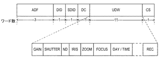
図2に、本実施例の補助データパケット構造を示す。ADF(補助データフラグ)、DID(データ識別ワード)、SDID(第2データ識別ワード)、DC(データカウントワード)、UDW(ユーザデータワード)、CS(チェックサムワード)から構成されている。ADF、DID、SDIDは、所定の値となっており、UDWは、11ワードで構成している。 FIG. 2 shows an auxiliary data packet structure of the present embodiment. ADF (auxiliary data flag), DID (data identification word), SDID (second data identification word), DC (data count word), UDW (user data word), and CS (check sum word). ADF, DID, and SDID have predetermined values, and UDW is composed of 11 words.
本実施例では、図2のように録画開始コマンドをUDWの11ワード目(以下、UDW10)のビット番号b1を1にすることで、録画開始としている。また、UDW10のb1を0にすることで、録画停止としている。尚、本実施例では、SMPTEで規定されている第2形式の補助データパケット構造を使用しているが、第1形式の補助データパケット構造にしても構わない。 In this embodiment, as shown in FIG. 2, the recording start command is set to the recording start by setting the bit number b1 of the eleventh word of the UDW (hereinafter, UDW10) to 1. Recording is stopped by setting b1 of the UDW 10 to 0. Although the second embodiment uses the second format auxiliary data packet structure defined by SMPTE, the first format auxiliary data packet structure may be used.
外部録画機器300は、映像信号1出力部105から出力されるSDI信号の補助データパケットから、所定のDID、SDIDを検出し、UDW10のビット番号b1が1の場合、録画を開始するようになっている。一方、UDW10のb1が0の場合、録画を停止する。
The
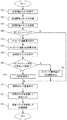
次に、撮像装置100がオンスクリーン中にオンスクリーン映像を誤って録画してしまうことを防止するためのフローについて図3を用いて説明する。
Next, a flow for preventing the
操作部108、または、外部操作器200から所定の録画開始スイッチが押下されると(ステップS1)、撮像装置100のCPU103に所定の録画開始コマンドを送信する(ステップS2)。CPU103が所定の録画開始コマンドを受信すると(ステップS3)、オンスクリーン表示有無を検出する(ステップS4)。オンスクリーン表示中の場合、CPU103は、オンスクリーン生成部104にオンスクリーン表示を停止する指令信号を送信する(ステップS5)。オンスクリーン表示中でない場合は、ステップS7へ進む。オンスクリーン生成部104は、映像信号処理部102に送信していたOSD情報の送信を停止する(ステップS6)。次に、CPU103は、映像信号1出力部105及び映像信号2出力部106へ録画開始コマンドを重畳するように指令信号を送信する(ステップS7)。映像信号1出力部105及び映像信号2出力部106は、補助データパケットのUDW10のビット番号b1を1にして所定のフォーマットで出力する(ステップS8)。最後に、外部録画機器300は、補助データパケットの所定のDID、SDIDを検出し、UDW10のビット番号b1が、1であるので録画を開始する(ステップS9)。
When a predetermined recording start switch is pressed from the
すなわち、録画機器での録画開始コマンドが入力された場合、映像信号処理部は、撮像部によって取得された映像信号に対して、撮像関連情報を重畳せず、映像信号出力部は、撮像関連情報が重畳されていない映像信号を、出力映像信号として録画機器に出力する。 That is, when a recording start command in the recording device is input, the video signal processing unit does not superimpose the imaging-related information on the video signal acquired by the imaging unit, and the video signal output unit outputs the imaging-related information. Is output to a recording device as an output video signal.
以上説明してきたように、撮像装置100は、オンスクリーン表示中に誤って録画開始コマンドを操作部108、または、外部操作器200から受信しても、オンスクリーン表示を非表示にして、録画開始コマンドを所定のフォーマットに重畳して出力する。これにより、オンスクリーン表示中の映像を誤って録画することを防止することが可能となる。また、オンスクリーン中に、急遽録画開始が必要となった時、オンスクリーン表示を非表示にするため、操作部108、または、外部操作器200の所定のスイッチを押下してオンスクリーンを非表示にする手間を省くことも可能である。
As described above, even when the
実施例1では、外部操作器200で所定の録画開始スイッチが押下されると、CPU103は、オンスクリーン表示有無を判断し、オンスクリーン表示の時は、オンスクリーンを非表示にしていた。本実施例では、外部操作器200で所定の録画開始スイッチが押下されると、撮像装置100にオンスクリーン表示を非表示にするコマンドを送信後、録画開始コマンドを送信することが実施例1と異なる。
In the first embodiment, when a predetermined recording start switch is pressed by the
撮像装置100の構成図は、実施例1の図1と同じなので説明は省略する。
The configuration diagram of the
図4は、外部操作器200の構成図である。外部操作器200は、操作部201、通信部202、CPU203から構成されている。操作部201は、撮像装置100、及び、外部操作器200の操作を行うためのキースイッチや、タッチパネル等である。通信部202は、撮像装置100とRS−232CやRS−422等の所定のファーマットで送受信するためのインタフェースである。CPU203は、操作部201、通信部202と各々接続され、各部の設定や制御を行っている。
FIG. 4 is a configuration diagram of the
図5は、本実施例のフローチャート図である。 FIG. 5 is a flowchart of the present embodiment.
外部操作器200の操作部201から所定の録画開始スイッチが押下されると(ステップS21)、外部操作器200のCPU203は、所定のオンスクリーン表示を中止するコマンドを通信部202を経由して撮像装置100へ送信する(ステップS22)。撮像装置100は、所定のオンスクリーン表示を中止するコマンドを受信すると(ステップS23)、ステップS24、ステップS25へ進む。ステップS24、ステップS25は、実施例1の図3フローチャートのステップS6、ステップS7と同じなので説明は省略する。次に外部操作器200のCPU203は、録画開始コマンドを送信すると(ステップS26)、撮像装置100は、録画開始コマンドを受信する(ステップS27)。その後は、ステップS28〜S30を実行する。ステップS28〜S30は、実施例1の図3フローチャートのステップS7〜ステップS9と同じなので説明は省略する。本実施例では外部操作器200は、撮像装置100が、オンスクリーン表示の有無にかかわらず録画開始スイッチが押下されるとオンスクリーン表示を中止するコマンドを最初に送信し、その後録画開始コマンドを送信している。撮像装置100が、オンスクリーン表示中でない場合は、オンスクリーン表示を中止するコマンドを送信しないようにしても構わない。
When a predetermined recording start switch is pressed from the
以上説明してきたように、外部操作器200は、録画開始スイッチを押下すると、最初にオンスクリーンを非表示にするコマンドを送信するため、誤ってオンスクリーン表示している映像を録画することを防止することが可能となる。
As described above, when the recording start switch is pressed, the
実施例1では、撮像装置100がオンスクリーン表示中に操作部108、または、外部操作器200から録画開始コマンドを受信すると、オンスクリーン表示を非表示にして、外部録画機器300に録画開始コマンドを送信していた。実施例3では、撮像装置100がオンスクリーン中に録画開始コマンドを受信すると、メッセージを表示してユーザーにオンスクリーン表示中であることを注意喚起し、外部録画機器300に録画コマンドを送信しないようにしている。実施例3の構成は、図1と同じであるので説明は省略する。
In the first embodiment, when the
図6に本実施例のフローチャートを示す。
ステップS41〜ステップS44は、実施例1の図3フローチャートのステップS1〜ステップS4と同じなので説明は省略する。
FIG. 6 shows a flowchart of this embodiment.
Steps S41 to S44 are the same as steps S1 to S4 in the flowchart of FIG.
ステップS44でオンスクリーン表示中の場合、CPU103は、オンスクリーン生成部104に図7のようなメッセージ画面を表示する指令信号を送信する(ステップS45)。オンスクリーン生成部104は、メッセージ画面用OSD情報を映像信号処理部102に送信する(ステップS46)。ステップS44でオンスクリーン表示中でない場合は、ステップS50へ進む。操作部108、または、外部操作器200から所定のスイッチが押下され(ステップS47)、オンスクリーン映像を消去して録画する場合は、ステップS49〜S52へ進む。ステップS49〜S52は、実施例1の図3フローチャートのステップS6〜S9と同じなので説明は省略する。ステップS48で操作部108、または、外部操作器200から所定のスイッチが押下され、オンスクリーン映像をそのまま録画する場合は、メッセージ画面を表示する前のOSD情報を送信する(ステップS53)(オンスクリーン表示を継続する)。その後は、ステップS50〜S52へ進む。
If the on-screen display is being performed in step S44, the
以上説明してきたように実施例3では、撮像装置100がオンスクリーン表示中に誤って録画開始コマンドを操作部108、または、外部操作器200から受信した場合、メッセージ画面を表示してユーザーに注意喚起を促し、追加の指令を要求する。これにより、オンスクリーン中に誤って録画を開始することを防止することが可能となる。また、オンスクリーン中に、ユーザーが意図的にオンスクリーン映像を録画することも可能である。
As described above, in the third embodiment, when the
実施例4は、撮像装置100がオンスクリーン表示中に操作部108、または、外部操作器200から録画開始コマンドを受信した時、オンスクリーン表示の内容によってオンスクリーン表示のまま、または、非表示にして外部録画機器300に録画開始コマンドを送信する。この点において本実施例は実施例1〜3とは異なる。構成は、実施例1の図1と同じなので説明は省略する。
In the fourth embodiment, when the
図8(a)、(b)、(c)、(d)は、撮像映像にオンスクリーン表示した時の表示例である。(a)は、撮像装置100のメインメニュの表示例である。(b)は、撮像装置100のカメラ設定メニュの表示例である。(c)は、撮像装置100の現在の設定状況を表示しているステータス画面の表示例である。(d)は、現在の日時を表示している表示例である。
FIGS. 8A, 8B, 8C, and 8D show display examples when on-screen display is performed on a captured image. (A) is a display example of a main menu of the
本実施例では、オンスクリーンの表示例(a)、(b)の時は、オンスクリーン表示が撮像映像を遮蔽している面積が多く、ユーザーが誤って録画開始スイッチを押下してしまったと考えられる。よって、オンスクリーン表示を非表示にして録画開始コマンドを外部録画機器300に送信する。一方、オンスクリーンの表示例(c)、(d)の時は、オンスクリーン表示による撮像映像の遮蔽面積が少なく、周辺のみオンスクリーン表示されているためユーザーが意図してオンスクリーン表示のまま録画したいと考えられる。よって、オンスクリーン表示のまま録画開始コマンドを外部録画機器300に送信する。
In this embodiment, in the case of the on-screen display examples (a) and (b), it is considered that the area where the on-screen display blocks the captured image is large, and the user has accidentally pressed the recording start switch. Can be Therefore, the on-screen display is hidden, and the recording start command is transmitted to the
図9に本実施例のフローチャートを示す。本実施例では、ステップS70を入れた以外は、実施例1の図3フローチャートと同じである。ステップS70で、CPU103は、オンスクリーン表示されている映像の内容を判断し、表示内容に応じてオンスクリーン表示を中止するか、表示したままにするかを決定し、次のステップS65、または、S67に進む。図7でステップS61〜ステップS69は、実施例1の図3フローチャートのステップS1〜S9と同じなので説明は省略する。
FIG. 9 shows a flowchart of this embodiment. This embodiment is the same as the flowchart in FIG. 3 of the first embodiment except that step S70 is included. In step S70, the
以上説明してきたように実施例4では、撮像装置100がオンスクリーン表示中に録画開始コマンドを操作部108、または、外部操作器200から受信した場合、誤って録画開始コマンドを送信したのか、意図的に録画開始コマンドを送信したのかを判断している。これにより、オンスクリーン中に誤って録画を開始することを防止することが可能となる。
As described above, according to the fourth embodiment, when the
実施例5は、撮像装置100がオンスクリーン表示中に操作部108、または、外部操作器200から録画開始コマンドを受信した時、オンスクリーン表示の内容によりオンスクリーン表示の可否を事前かつ個別に設定できる設定メニュ画面を新たに設ける。この点において本実施例は実施例4と異なる。構成は、実施例1の図1と同じなので説明は省略する。
In the fifth embodiment, when the
図10は、個別設定メニュの表示例である。操作部108、または、外部操作器200から所定のボタンを押下して、オンスクリーン表示する内容ごとに個別に設定できるようになっている。
FIG. 10 is a display example of the individual setting menu. By pressing a predetermined button from the
図11に本実施例のフローチャートを示す。ステップS81〜ステップS89までは、実施例1の図3フローチャートのステップS1〜S9と同じなので説明は省略する。図11のステップS90で、CPU103は、事前に設定されたオンスクリーン表示する内容ごとの個別設定に従いオンスクリーン表示しない場合、ステップS85へ、オンスクリーン表示する場合は、ステップS87へ進む。
FIG. 11 shows a flowchart of this embodiment. Steps S81 to S89 are the same as steps S1 to S9 in the flowchart of FIG. In step S90 of FIG. 11, the
以上説明してきたように実施例5では、撮像装置100がオンスクリーン表示中に録画開始コマンドを操作部108、または、外部操作器200から受信した場合、オンスクリーン表示/非表示を事前かつ個別に設定することが可能となる。これにより、オンスクリーン中にオンスクリーン映像を誤って録画開始することを防止することができる。
As described above, in the fifth embodiment, when the recording start command is received from the
また、図1の構成例の映像信号1出力部105、映像信号2出力部106各々の出力に対して、オンスクリーン表示/非表示を事前かつ個別に設定することも可能となる。
Further, it is also possible to set on-screen display / non-display in advance and individually for each output of the
実施例6は、撮像装置100がオンスクリーン表示中に操作部108、または、外部操作器200から録画開始コマンドを受信した時、オンスクリーン表示を非表示にして、補助データパケットのUDWに録画開始コマンドだけではなく、撮像装置100の設定値も重畳する。この点において、本実施例は実施例1〜5と異なる。
In the sixth embodiment, when the
具体的には図12の補助データパケットのUDWに、録画開始コマンド以外に、ゲイン、シャッター、NDフィルタ、絞り、ズーム、フォーカス、日時等の値を重畳する。補助データパケットに重畳する撮像装置100の設定値を設定メニュ画面を設けて事前に設定できるようにしても構わない。
More specifically, in addition to the recording start command, values such as gain, shutter, ND filter, aperture, zoom, focus, date and time are superimposed on the UDW of the auxiliary data packet in FIG. The setting value of the
以上のように、撮像装置100は、オンスクリーン表示中に誤って録画開始コマンドを受信しても、オンスクリーン表示を非表示にして、録画開始コマンド及び撮像装置100の設定値を所定のファーマットで重畳して出力する。これにより、オンスクリーン表示中の映像を誤って録画することを防止することが可能となる。また、撮像装置100の設定状態を補助データパケットに重畳するため、後から、その映像が撮像された時の設定状態を確認することも可能である。
As described above, even when the
例示した実施例では、録画開始コマンドを受信した場合、映像信号処理部での処理で撮像関連情報を重畳しない処理を実行したが、本発明はこれに限定されることはない。録画開始コマンドを受信した場合、映像信号処理部を介さずに撮像部からの映像信号を録画機器に出力するようにしても本発明の効果を享受することができる。 In the illustrated embodiment, when the recording start command is received, the processing in the video signal processing unit that does not superimpose the imaging-related information is executed, but the present invention is not limited to this. When the recording start command is received, the effect of the present invention can be enjoyed even if the video signal from the imaging unit is output to the recording device without passing through the video signal processing unit.
100 撮像装置
101 撮像部
102 映像信号処理部(映像処理部)
103 CPU(制御部)
104 オンスクリーン生成部(生成部)
105 映像信号1出力部(出力部)
107 通信部(指令入力手段)
108 操作部(指令入力手段)
100
103 CPU (control unit)
104 On-screen generation unit (generation unit)
105
107 communication unit (command input means)
108 Operation unit (command input means)
Claims (6)
撮像関連情報を生成する生成部と、
前記撮像部によって取得された映像信号に前記撮像関連情報を重畳することが可能な映像処理部と、
前記撮像関連情報が重畳されている前記映像信号または前記撮像関連情報が重畳されていない前記映像信号を録画機器へ出力する出力部と、を備える撮像装置であって、
前記録画機器での録画開始指令が指令入力手段から入力された場合、前記撮像関連情報の内容に基づいて前記映像処理部による前記重畳を継続または中止した後に、前記録画開始指令を前記録画機器へ出力する、
ことを特徴とする撮像装置。 An imaging unit;
A generation unit that generates imaging-related information;
A video processing unit capable of superimposing the imaging-related information on a video signal acquired by the imaging unit;
An output unit that outputs the video signal on which the imaging-related information is superimposed or the video signal on which the imaging-related information is not superimposed to a recording device,
When a recording start command in the recording device is input from a command input unit, after continuing or stopping the superimposition by the video processing unit based on the content of the imaging related information, the recording start command is sent to the recording device. Output,
An imaging device characterized by the above-mentioned.
前記録画機器での録画開始指令が前記指令入力手段から入力された場合、前記設定手段の前記設定に基づいて前記映像処理部による前記重畳を継続または中止した後に、前記録画開始指令を前記録画機器へ出力する、
ことを特徴とする請求項1に記載の撮像装置。 Setting means for setting whether or not recording is possible for each of the imaging-related information,
When a recording start command in the recording device is input from the command input unit, after continuing or stopping the superimposition by the video processing unit based on the setting of the setting unit, the recording start command is transmitted to the recording device. Output to
The imaging device according to claim 1, wherein:
撮像関連情報を生成する生成部と、
前記撮像部によって取得された映像信号に前記撮像関連情報を重畳することが可能な映像処理部と、
前記撮像関連情報が重畳されている前記映像信号または前記撮像関連情報が重畳されていない前記映像信号を録画機器へ出力する出力部と、を備える撮像装置であって、
前記出力部は、前記映像信号をシリアルデジタル信号に変換し、
前記録画機器での録画開始指令が指令入力手段から入力された場合、前記映像処理部による前記重畳を中止し、前記録画開始指令及び前記撮像装置の設定値を映像データ以外の領域に含む前記シリアルデジタル信号を前記録画機器へ出力する、
ことを特徴とする撮像装置。 An imaging unit;
A generation unit that generates imaging-related information;
A video processing unit capable of superimposing the imaging-related information on a video signal acquired by the imaging unit;
An output unit that outputs the video signal on which the imaging-related information is superimposed or the video signal on which the imaging-related information is not superimposed to a recording device,
The output unit converts the video signal into a serial digital signal,
When a recording start command in the recording device is input from a command input unit, the superimposition by the video processing unit is stopped, and the serial including the recording start command and a setting value of the imaging device in an area other than video data. Outputting a digital signal to the recording device;
An imaging device characterized by the above-mentioned.
撮像関連情報を生成する生成部と、
前記撮像部によって取得された映像信号に前記撮像関連情報を重畳することが可能な映像処理部と、
前記撮像関連情報が重畳されている前記映像信号または前記撮像関連情報が重畳されていない前記映像信号を録画機器へ出力する出力部と、を備える撮像装置であって、
前記録画機器での録画開始指令が指令入力手段から入力された場合、前記映像処理部による前記重畳の可否に関する指令を待ち、前記指令入力手段から前記重畳の可否に関する指令の入力がない場合、前記録画開始指令を前記録画機器へ出力しない、
ことを特徴とする撮像装置。 An imaging unit;
A generation unit that generates imaging-related information;
A video processing unit capable of superimposing the imaging-related information on a video signal acquired by the imaging unit;
An output unit that outputs the video signal on which the imaging-related information is superimposed or the video signal on which the imaging-related information is not superimposed to a recording device,
When a recording start command in the recording device is input from the command input unit, waits for a command regarding whether or not the superimposition is possible by the video processing unit. Do not output a recording start command to the recording device,
An imaging device characterized by the above-mentioned.
前記録画機器での録画開始を指令する操作がされた場合、前記重畳を中止させる指令を前記撮像装置へ出力した後に、前記録画機器での録画開始指令を前記撮像装置へ出力する、
ことを特徴とする外部操作器。 An imaging unit, a generation unit that generates imaging-related information, a video processing unit that can superimpose the imaging-related information on a video signal acquired by the imaging unit, and the imaging-related information that is superimposed. An output unit for outputting the video signal or the video signal, on which the imaging-related information is not superimposed, to a recording device, and an external operating device for communicating with the imaging device, and operating the imaging device,
If the operation of instructing the start of recording in the recording device is performed, after outputting a command to stop the superimposition to the imaging device, output a recording start command in the recording device to the imaging device,
An external operation device characterized by the above-mentioned.
Priority Applications (1)
| Application Number | Priority Date | Filing Date | Title |
|---|---|---|---|
| JP2015139350A JP6666024B2 (en) | 2015-07-13 | 2015-07-13 | Imaging device and external operation device for operating the same |
Applications Claiming Priority (1)
| Application Number | Priority Date | Filing Date | Title |
|---|---|---|---|
| JP2015139350A JP6666024B2 (en) | 2015-07-13 | 2015-07-13 | Imaging device and external operation device for operating the same |
Publications (3)
| Publication Number | Publication Date |
|---|---|
| JP2017022588A JP2017022588A (en) | 2017-01-26 |
| JP2017022588A5 JP2017022588A5 (en) | 2018-08-09 |
| JP6666024B2 true JP6666024B2 (en) | 2020-03-13 |
Family
ID=57888470
Family Applications (1)
| Application Number | Title | Priority Date | Filing Date |
|---|---|---|---|
| JP2015139350A Active JP6666024B2 (en) | 2015-07-13 | 2015-07-13 | Imaging device and external operation device for operating the same |
Country Status (1)
| Country | Link |
|---|---|
| JP (1) | JP6666024B2 (en) |
-
2015
- 2015-07-13 JP JP2015139350A patent/JP6666024B2/en active Active
Also Published As
| Publication number | Publication date |
|---|---|
| JP2017022588A (en) | 2017-01-26 |
Similar Documents
| Publication | Publication Date | Title |
|---|---|---|
| JP2012049825A (en) | Communication apparatus | |
| EP2866434A1 (en) | Imaging apparatus | |
| JP2007067730A (en) | Imaging apparatus | |
| JP2018093305A (en) | Display device, control method for the same, program, and storage medium | |
| US20220303462A1 (en) | Electronic apparatus, image capture apparatus, method for controlling the same, and storage medium | |
| US9263001B2 (en) | Display control device | |
| JP5094583B2 (en) | Imaging apparatus, data communication system, and data communication method | |
| JP6666024B2 (en) | Imaging device and external operation device for operating the same | |
| US20220247917A1 (en) | Image capture apparatus, operation apparatus and control methods | |
| JP2008092418A (en) | Television operation system and television receiver | |
| US20230217105A1 (en) | Imaging device, imaging control device, control method of imaging device, and program | |
| JP2008122507A (en) | Screen display processor, video display device, and osd display method | |
| JP2013090243A (en) | Image output device and image display device | |
| WO2015125420A1 (en) | Imaging apparatus and imaging system | |
| JP5509590B2 (en) | Electronic camera | |
| JP4789866B2 (en) | Reservation execution method, reservation execution system, and display device | |
| US20220377249A1 (en) | Image capturing apparatus, control method thereof, and storage medium | |
| JP2017022589A (en) | Imaging device | |
| US20230199304A1 (en) | Information processing apparatus, information processing method, imaging apparatus, control method, and storage medium | |
| US20240040239A1 (en) | Display control apparatus, display control method, and storage medium | |
| JP2018182563A (en) | Display controller, control method thereof, program, and storage medium | |
| JP2018033060A (en) | Imaging apparatus | |
| US20240048841A1 (en) | Display control apparatus, control method thereof, and storage medium | |
| US20240040231A1 (en) | Image capturing apparatus and control method | |
| JP6889622B2 (en) | Image processing device and its control method and program |
Legal Events
| Date | Code | Title | Description |
|---|---|---|---|
| RD05 | Notification of revocation of power of attorney |
Free format text: JAPANESE INTERMEDIATE CODE: A7425 Effective date: 20171214 |
|
| RD04 | Notification of resignation of power of attorney |
Free format text: JAPANESE INTERMEDIATE CODE: A7424 Effective date: 20180126 |
|
| A521 | Request for written amendment filed |
Free format text: JAPANESE INTERMEDIATE CODE: A523 Effective date: 20180628 |
|
| A621 | Written request for application examination |
Free format text: JAPANESE INTERMEDIATE CODE: A621 Effective date: 20180628 |
|
| A977 | Report on retrieval |
Free format text: JAPANESE INTERMEDIATE CODE: A971007 Effective date: 20190411 |
|
| A131 | Notification of reasons for refusal |
Free format text: JAPANESE INTERMEDIATE CODE: A131 Effective date: 20190521 |
|
| A521 | Request for written amendment filed |
Free format text: JAPANESE INTERMEDIATE CODE: A523 Effective date: 20190710 |
|
| A131 | Notification of reasons for refusal |
Free format text: JAPANESE INTERMEDIATE CODE: A131 Effective date: 20191224 |
|
| A521 | Request for written amendment filed |
Free format text: JAPANESE INTERMEDIATE CODE: A523 Effective date: 20200110 |
|
| TRDD | Decision of grant or rejection written | ||
| A01 | Written decision to grant a patent or to grant a registration (utility model) |
Free format text: JAPANESE INTERMEDIATE CODE: A01 Effective date: 20200121 |
|
| A61 | First payment of annual fees (during grant procedure) |
Free format text: JAPANESE INTERMEDIATE CODE: A61 Effective date: 20200218 |
|
| R151 | Written notification of patent or utility model registration |
Ref document number: 6666024 Country of ref document: JP Free format text: JAPANESE INTERMEDIATE CODE: R151 |