JP6662167B2 - Pulse wave detection device, biological information measurement device, mounting aid for pulse wave detection device - Google Patents
Pulse wave detection device, biological information measurement device, mounting aid for pulse wave detection device Download PDFInfo
- Publication number
- JP6662167B2 JP6662167B2 JP2016082370A JP2016082370A JP6662167B2 JP 6662167 B2 JP6662167 B2 JP 6662167B2 JP 2016082370 A JP2016082370 A JP 2016082370A JP 2016082370 A JP2016082370 A JP 2016082370A JP 6662167 B2 JP6662167 B2 JP 6662167B2
- Authority
- JP
- Japan
- Prior art keywords
- wrist
- band
- pulse wave
- mounting
- auxiliary member
- Prior art date
- Legal status (The legal status is an assumption and is not a legal conclusion. Google has not performed a legal analysis and makes no representation as to the accuracy of the status listed.)
- Active
Links
- 238000001514 detection method Methods 0.000 title claims description 40
- 238000005259 measurement Methods 0.000 title description 4
- 210000000707 wrist Anatomy 0.000 claims description 104
- 210000000623 ulna Anatomy 0.000 claims description 30
- 210000002321 radial artery Anatomy 0.000 claims description 11
- 239000000463 material Substances 0.000 description 10
- 230000004048 modification Effects 0.000 description 5
- 238000012986 modification Methods 0.000 description 5
- 238000010586 diagram Methods 0.000 description 4
- 238000006073 displacement reaction Methods 0.000 description 4
- 230000002093 peripheral effect Effects 0.000 description 3
- 238000003825 pressing Methods 0.000 description 3
- 239000011347 resin Substances 0.000 description 3
- 229920005989 resin Polymers 0.000 description 3
- 230000036772 blood pressure Effects 0.000 description 2
- 238000005520 cutting process Methods 0.000 description 2
- 230000000694 effects Effects 0.000 description 2
- 238000004519 manufacturing process Methods 0.000 description 2
- 239000002184 metal Substances 0.000 description 2
- 239000005060 rubber Substances 0.000 description 2
- 239000000853 adhesive Substances 0.000 description 1
- 230000001070 adhesive effect Effects 0.000 description 1
- 210000001367 artery Anatomy 0.000 description 1
- 230000008602 contraction Effects 0.000 description 1
- 239000013013 elastic material Substances 0.000 description 1
- 239000004744 fabric Substances 0.000 description 1
- 239000010985 leather Substances 0.000 description 1
- 238000000034 method Methods 0.000 description 1
- 239000002023 wood Substances 0.000 description 1
Images


Classifications
-
- A—HUMAN NECESSITIES
- A61—MEDICAL OR VETERINARY SCIENCE; HYGIENE
- A61B—DIAGNOSIS; SURGERY; IDENTIFICATION
- A61B5/00—Measuring for diagnostic purposes; Identification of persons
- A61B5/02—Detecting, measuring or recording pulse, heart rate, blood pressure or blood flow; Combined pulse/heart-rate/blood pressure determination; Evaluating a cardiovascular condition not otherwise provided for, e.g. using combinations of techniques provided for in this group with electrocardiography or electroauscultation; Heart catheters for measuring blood pressure
- A61B5/021—Measuring pressure in heart or blood vessels
- A61B5/02108—Measuring pressure in heart or blood vessels from analysis of pulse wave characteristics
-
- A—HUMAN NECESSITIES
- A61—MEDICAL OR VETERINARY SCIENCE; HYGIENE
- A61B—DIAGNOSIS; SURGERY; IDENTIFICATION
- A61B5/00—Measuring for diagnostic purposes; Identification of persons
- A61B5/02—Detecting, measuring or recording pulse, heart rate, blood pressure or blood flow; Combined pulse/heart-rate/blood pressure determination; Evaluating a cardiovascular condition not otherwise provided for, e.g. using combinations of techniques provided for in this group with electrocardiography or electroauscultation; Heart catheters for measuring blood pressure
- A61B5/024—Detecting, measuring or recording pulse rate or heart rate
- A61B5/0245—Detecting, measuring or recording pulse rate or heart rate by using sensing means generating electric signals, i.e. ECG signals
-
- A—HUMAN NECESSITIES
- A61—MEDICAL OR VETERINARY SCIENCE; HYGIENE
- A61B—DIAGNOSIS; SURGERY; IDENTIFICATION
- A61B5/00—Measuring for diagnostic purposes; Identification of persons
- A61B5/68—Arrangements of detecting, measuring or recording means, e.g. sensors, in relation to patient
- A61B5/6801—Arrangements of detecting, measuring or recording means, e.g. sensors, in relation to patient specially adapted to be attached to or worn on the body surface
- A61B5/6802—Sensor mounted on worn items
- A61B5/681—Wristwatch-type devices
-
- A—HUMAN NECESSITIES
- A61—MEDICAL OR VETERINARY SCIENCE; HYGIENE
- A61B—DIAGNOSIS; SURGERY; IDENTIFICATION
- A61B5/00—Measuring for diagnostic purposes; Identification of persons
- A61B5/02—Detecting, measuring or recording pulse, heart rate, blood pressure or blood flow; Combined pulse/heart-rate/blood pressure determination; Evaluating a cardiovascular condition not otherwise provided for, e.g. using combinations of techniques provided for in this group with electrocardiography or electroauscultation; Heart catheters for measuring blood pressure
- A61B5/021—Measuring pressure in heart or blood vessels
- A61B5/022—Measuring pressure in heart or blood vessels by applying pressure to close blood vessels, e.g. against the skin; Ophthalmodynamometers
-
- A—HUMAN NECESSITIES
- A61—MEDICAL OR VETERINARY SCIENCE; HYGIENE
- A61B—DIAGNOSIS; SURGERY; IDENTIFICATION
- A61B5/00—Measuring for diagnostic purposes; Identification of persons
- A61B5/72—Signal processing specially adapted for physiological signals or for diagnostic purposes
- A61B5/7235—Details of waveform analysis
Landscapes
- Health & Medical Sciences (AREA)
- Life Sciences & Earth Sciences (AREA)
- Cardiology (AREA)
- Engineering & Computer Science (AREA)
- Animal Behavior & Ethology (AREA)
- Surgery (AREA)
- Biomedical Technology (AREA)
- Heart & Thoracic Surgery (AREA)
- General Health & Medical Sciences (AREA)
- Molecular Biology (AREA)
- Pathology (AREA)
- Biophysics (AREA)
- Medical Informatics (AREA)
- Public Health (AREA)
- Veterinary Medicine (AREA)
- Physics & Mathematics (AREA)
- Physiology (AREA)
- Vascular Medicine (AREA)
- Signal Processing (AREA)
- Measuring Pulse, Heart Rate, Blood Pressure Or Blood Flow (AREA)
Description
本発明は、脈波検出装置、生体情報測定装置、脈波検出装置の装着補助部材に関する。 The present invention relates to a pulse wave detecting device, a biological information measuring device, and a mounting assisting member of the pulse wave detecting device.
手首の橈骨動脈等の動脈が通る生体部位にセンサを直接接触させた状態で、このセンサにより検出される情報を用いて心拍数、脈拍数、又は、血圧等の生体情報を測定することのできる生体情報測定装置が知られている(特許文献1、2参照)。 In a state where the sensor is directly in contact with a living body part through which an artery such as a radial artery of a wrist passes, biological information such as a heart rate, a pulse rate, or a blood pressure can be measured using information detected by the sensor. A biological information measuring device is known (see Patent Documents 1 and 2).
特許文献1には、センサを収容する筐体のみで手首への装着を行う生体情報測定装置が記載されている。この生体情報測定装置の筐体は、手首に装着した状態で、手の甲側に巻きつけられる部分に尺骨を避けるための開口が設けられており、この開口によって装置の手首への装着状態を安定して維持させることを可能にしている。 Patent Literature 1 describes a biological information measurement device that is mounted on a wrist only with a housing that accommodates a sensor. The housing of this biological information measuring device is provided with an opening to avoid the ulna in a part that is wound around the back of the hand when mounted on the wrist, and this opening stabilizes the mounting state of the device on the wrist. And maintain it.
特許文献2には、手首に巻きつけるバンド部の両端部を3つに分割し、分割された各バンド部の一端と他端を個別に固定できるようにした生体情報測定装置が記載されている。 Patent Literature 2 discloses a biological information measuring device in which both end portions of a band portion wound around a wrist are divided into three, and one end and the other end of each of the divided band portions can be individually fixed. .
特許文献1の生体情報測定装置は、筐体の素材及び形状を工夫する必要があるため、装置の製造コストが増大する。製造コストを抑えるには、バンドを用いて筐体を手首に固定する構成が有効である。しかし、手首には、尺骨が突き出た部分があるため、バンドを締め付ける際に、バンドが尺骨に当たることで装置の装着感又は装着の容易性が損なわれたり、装着後に装置の位置ずれが生じたりする可能性がある。 In the biological information measuring device disclosed in Patent Document 1, it is necessary to devise the material and shape of the housing, so that the manufacturing cost of the device increases. In order to reduce the manufacturing cost, it is effective to use a band to fix the housing to the wrist. However, since the wrist has a portion where the ulna protrudes, the band may hit the ulna when tightening the band, impairing the feeling of wearing or easiness of mounting the device, or causing the device to shift after mounting. there's a possibility that.
バンドに伸縮性の高いものを採用すれば、装置の装着感又は装着の容易性を向上させることは可能である。しかし、伸縮性の高いバンドでは、装置を手首に固定した後に、バンド部分の伸縮が原因でセンサ部分の位置にずれが生じる可能性があり、精度よく生体情報を測定することが難しい。 If a band having high elasticity is used for the band, it is possible to improve the wearing feeling or the ease of wearing of the device. However, in the case of a band with high elasticity, after the device is fixed to the wrist, the position of the sensor part may be shifted due to the expansion and contraction of the band part, and it is difficult to accurately measure biological information.
特許文献2の生体情報測定装置は、バンドの各分割部分にセンサを固定することで、各センサの押し当て位置を調整可能にするものである。しかし、バンドそのものにセンサが設けられているため、手の動きによってセンサ位置がずれる可能性が高く、生体情報を高精度に測定することができない。 The biological information measuring device of Patent Literature 2 fixes a sensor at each divided portion of a band, thereby enabling adjustment of a pressing position of each sensor. However, since the band itself is provided with the sensor, the position of the sensor is likely to be shifted due to the movement of the hand, and the biological information cannot be measured with high accuracy.
上述した課題は、圧力センサ等によって圧脈波を検出する生体情報測定装置に限らず、例えば光電センサによって容積脈波を検出する生体情報測定装置についても同様に生じる。 The above-described problem occurs not only in a biological information measuring device that detects a pressure pulse wave using a pressure sensor or the like, but also occurs in a biological information measuring device that detects a volume pulse wave using a photoelectric sensor, for example.
本発明は、上記事情に鑑みてなされたものであり、手首への装着感と装着の容易性を向上させ、かつ、精度よく脈波を検出することのできる脈波検出装置と、これを備える生体情報測定装置と、脈波検出装置に用いられる装着補助部材を提供することを目的とする。 The present invention has been made in view of the above circumstances, and improves a feeling of wearing on a wrist and easiness of wearing, and includes a pulse wave detecting device capable of detecting a pulse wave with high accuracy. It is an object of the present invention to provide a biological information measuring device and a wearing auxiliary member used for a pulse wave detecting device.
本発明の脈波検出装置は、被測定者の手首に装着して用いられる脈波検出装置であって、前記被測定者の橈骨動脈から脈波を検出可能な検出部を含む本体部と、前記本体部を前記手首に固定するための帯状のバンドと、前記バンドに対して着脱可能に構成された装着補助部材と、を備え、前記バンドは、前記装着補助部材の装着箇所では、該装着補助部材を介して前記手首に接触し、前記装着補助部材は、前記手首との接触面に、前記バンドに装着された状態での前記バンドの短手方向における両端部と、前記両端部の間に形成された、尺骨の突起が挿入可能な凹部と、を有し、前記装着補助部材は、前記装着補助部材が装着された前記バンドによって前記本体部が前記手首に固定された固定状態において、前記尺骨の突起が前記凹部に入り、前記両端部が前記手首と接触するように固定されるものである。 The pulse wave detection device of the present invention is a pulse wave detection device used by being worn on the wrist of the subject, a main body including a detection unit capable of detecting a pulse wave from the radial artery of the subject, A band-shaped band for fixing the main body to the wrist; and a mounting auxiliary member detachably attached to the band , wherein the band is attached at a mounting position of the mounting auxiliary member. The wrist is contacted via an auxiliary member, and the mounting auxiliary member is provided on the contact surface with the wrist, between both ends in the short direction of the band when attached to the band, and between the both ends. Formed in, has a recess into which the protrusion of the ulna can be inserted, and the mounting auxiliary member is in a fixed state in which the main body is fixed to the wrist by the band to which the mounting auxiliary member is mounted, The projection of the ulna enters the recess In which said end portion is fixed to be in contact with the wrist.
本発明の生体情報測定装置は、前記脈波検出装置と、前記脈波検出装置によって検出された脈波に基づいて生体情報を算出する生体情報算出部と、を備えるものである。 A biological information measuring device according to the present invention includes the pulse wave detecting device, and a biological information calculating unit that calculates biological information based on a pulse wave detected by the pulse wave detecting device.
本発明の脈波検出装置の装着補助部材は、被測定者の手首の橈骨動脈から脈波を検出可能な検出部を含む本体部と、前記本体部を前記手首に固定するための帯状のバンドとを有する脈波検出装置の装着補助部材であって、前記バンドに対して着脱可能に構成され、前記装着補助部材の装着箇所では、前記バンドに代わって前記手首に接触し、前記手首との接触面に、前記バンドに装着された状態での前記バンドの短手方向における両端部と、前記両端部の間に形成された、尺骨の突起が挿入可能な凹部と、を有し、前記装着補助部材が装着された前記バンドによって前記本体部が前記手首に固定された固定状態において、前記尺骨の突起が前記凹部に入り、前記両端部が前記手首と接触するように固定されるものである。 The mounting assisting member of the pulse wave detection device of the present invention includes a main body including a detection unit capable of detecting a pulse wave from a radial artery of a wrist of the subject, and a band-shaped band for fixing the main body to the wrist. And a detachable auxiliary member of the pulse wave detection device having the band, is configured to be detachable to the band, at the mounting portion of the mounting auxiliary member, in contact with the wrist instead of the band, and the wrist The contact surface has both ends in the short direction of the band attached to the band, and a recess formed between the both ends, into which a projection of the ulna can be inserted, and In a fixed state in which the main body is fixed to the wrist by the band to which the auxiliary member is attached, the protrusion of the ulna enters the concave portion and is fixed such that the both ends are in contact with the wrist. .
本発明によれば、手首への装着感と装着の容易性を向上させ、かつ、精度よく脈波を検出することのできる脈波検出装置と、これを備える生体情報測定装置と、脈波検出装置に用いられる装着補助部材を提供することができる。 Advantageous Effects of Invention According to the present invention, a pulse wave detection device capable of improving a feeling of wearing on a wrist and easiness of wearing, and detecting a pulse wave with high accuracy, a biological information measuring device including the same, and a pulse wave detection A mounting auxiliary member used for the device can be provided.
以下、本発明の実施形態について図面を参照して説明する。 Hereinafter, embodiments of the present invention will be described with reference to the drawings.
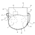
図1は、本発明の一実施形態である生体情報測定装置100の外観の概略構成を示す斜視図である。図1に示すように、生体情報測定装置100は、被測定者の左手の手首Wに装着して使用される。図2は、図1に示す生体情報測定装置100を被測定者の左手の肘側(被測定者の中枢側)から見た側面図である。ここでは生体情報測定装置100が左手の手首に装着される例を説明するが、生体情報測定装置100は右手の手首にも装着可能である。
FIG. 1 is a perspective view showing a schematic configuration of an external appearance of a biological
生体情報測定装置100は、金属製又は樹脂製等の筐体20と、筐体20を手首Wに固定するための部材である帯状のバンド40と、筐体20の手首Wへの装着を支援するための装着補助部材30と、を有する。
The biological
筐体20は、被測定者の手首Wの橈骨Tに沿う橈骨動脈TDから脈波(圧脈波又は容積脈波)を検出可能な脈波検出部22を含む。筐体20は、生体情報測定装置100の本体部を構成する。生体情報測定装置100の本体部は、筐体20のみで構成されていてもよいし、筐体20と、電池等が内蔵されるサブ筐体とが連結された構成(複数の筐体からなる構成)であってもよい。
The
脈波検出部22は、脈波を信号として出力することのできるセンサを少なくとも含む。例えば、脈波検出部22は、圧力センサとこれを皮膚に押し当てる押圧機構を有し、圧力センサによって圧脈波を検出する。または、脈波検出部22は、光電センサを有し、光電センサによって検出された信号から容積脈波を検出する。
The
筐体20は、図1の例では略箱状の部材であり、脈波検出部22と、脈波検出部22によって検出される脈波に基づいて心拍数、脈拍数、又は、血圧値等の生体情報を算出する図示しない生体情報算出部と、を含む。
The
生体情報算出部は、生体情報測定装置100とは別の機器に設けられるものであってもよい。つまり、生体情報測定装置100の筐体20(本体部)は、脈波検出部22を少なくとも含むものであればよい。この場合、生体情報測定装置100は脈波検出装置として機能する。
The biological information calculation unit may be provided in a device different from the biological
生体情報測定装置100が手首Wに装着される場合に手首Wと対向する筐体20の面は検出面を構成する。この検出面は略平面状であってもよいが、手首Wの外形に沿うように一部または全体が湾曲していてもよい。脈波検出部22は、この検出面が手首Wに対向した状態で、橈骨動脈TDに対向する位置に設けられている。
When the biological
筐体20における手首Wの周方向の両端部のうちの尺骨S側の第1端部28(図1及び図2の例では筐体20の尺骨S側の端面)には、第1係止部29が設けられている。
The
筐体20における手首Wの周方向の端部のうちの橈骨T側の第2端部26(図1及び図2の例では筐体20の橈骨T側の端面)には、第2係止部27が設けられている。
A second end 26 (the end face on the radius T side of the
第1係止部29及び第2係止部27は、バンド40を筐体20に対して係止するためのものである。第1係止部29及び第2係止部27は、それぞれ、バンド40を挿入可能な孔部を有する形状となっている。
The
バンド40は、基端部41が筐体20の第2係止部27に係止された状態で手首Wを周回するように配索される(バンド40と筐体20とで手首Wが挟まれる状態となるよう引き回される)ことにより、脈波検出部22を橈骨動脈TDに対面させた状態を維持して筐体20を手首Wに固定する。
The
バンド40は、例えば筐体20よりも剛性の低い部材である。バンド40の材料としては、例えば布、革、ゴム、又は、薄肉の樹脂等を用いることができる。
The
バンド40の長手方向の一端を構成する基端部41は、第2端部26に設けられている第2係止部27において折り返された状態で係止されている。
A
バンド40の長手方向の他端を構成する先端部43は、第1端部28に設けられている第1係止部29において折り返された状態で係止される。
The
具体的には、バンド40の先端部43は、第1係止部29の孔部に検出面側から挿入される。この孔部を通った先端部43は、筐体20から離れる方向に略U字状に折り返される。先端部43の非折り返し部分の筐体20側とは反対側を向く面と、先端部43の折り返し部分の筐体20側を向く面とにはそれぞれ面状ファスナ42が形成されている。この面状ファスナ42により、先端部43の折り返し部分はバンド40に対して着脱可能に係止される。
Specifically, the
面状ファスナ42は、バンド40に先端部43を着脱可能に係止するための係止部材である。なお、凹部とこれに嵌合可能な凸部とにより、バンド40に先端部43を着脱可能に係止する構成であってもよい。
The
装着補助部材30は、バンド40に対して着脱可能に構成された部材である。具体的には、装着補助部材30は、バンド40を通すことのできる貫通孔を有し、この貫通孔にバンド40が通されることで、バンド40に対して装着される。装着補助部材30は、バンド40を通しやすい材料(例えば木、金属、又は、樹脂)等によって構成されていることが好ましい。
The mounting
装着補助部材30の詳細構成について図3〜図5を用いて説明する。
The detailed configuration of the mounting
図3は、装着補助部材30が装着されたバンド40を模式的に示す平面図である。図3に示す方向Yはバンド40の長手方向を示す。図3に示す方向Xはバンド40の長手方向に直交する短手方向を示す。
FIG. 3 is a plan view schematically showing the
図4は、装着補助部材30の外観構成を模式的に示す斜視図である。図4(a)は、装着補助部材30が装着されたバンド40によって筐体20が手首Wに固定された状態(以下、固定状態という)での手首Wと対向する側とは反対側から装着補助部材30を見た斜視図である。図4(b)は、固定状態での手首Wと対向する側から装着補助部材30を見た斜視図である。
FIG. 4 is a perspective view schematically showing an external configuration of the mounting assisting
図5は、装着補助部材30の側面図である。図5(a)は、装着補助部材30を図3の方向Yから見た図である。図5(b)は、装着補助部材30を図3の方向Xから見た図である。図5には、図3に示した方向Xと方向Yの各々に直交する方向Z(固定状態において皮膚に押し当てられる方向)が示されている。
FIG. 5 is a side view of the mounting
図4に示すように、装着補助部材30の全体形状は、円柱を半分に切断した形状に近い形状となっている。装着補助部材30の表面31には、装着補助部材30の方向Yにおける一方の側面32にまで到達する貫通孔34と、装着補助部材30の方向Yにおける他方の側面33にまで到達する貫通孔35とが形成されている。貫通孔34に挿入されたバンド40は貫通孔35を通って側面33から引き出される。これにより、バンド40に対し、装着補助部材30が方向Yに向かって移動可能な状態で装着される。
As shown in FIG. 4, the overall shape of the mounting assisting
装着補助部材30の表面31の反対側の裏面36は、固定状態において被測定者の手首Wと対向する部分である。この裏面36には凹部36Aが形成されている。この凹部36Aは、被測定者の手首Wの尺骨Sの突起が挿入可能な程度の大きさになっている。
The
装着補助部材30は、固定状態では、手首Wの尺骨S近傍と接触する位置に配置されて使用される。手首Wの尺骨S近傍とは、手首Wにおいて尺骨Sを指で触ることのできる程度の範囲のことを言う。
In the fixed state, the mounting assisting
この凹部36Aがあることで、装着補助部材30が尺骨S近傍の皮膚に接触している状態でも、尺骨Sの突起を凹部36Aに挿入することができる。これにより、尺骨Sの突起と装着補助部材30との干渉を防いで、生体情報測定装置100の装着性を向上させることができる。
The presence of the
なお、図5(a)に示すように、装着補助部材30の方向Xにおける両端部の各々の裏面36の方向Zにおける位置は同じになっている。
In addition, as shown in FIG. 5A, the position in the direction Z of the
図5(b)に示すように、固定状態において手首Wと接触する裏面36は、手首Wの周方向に沿って湾曲する曲面となっている。これにより、裏面36と手首Wとの接触性を良好にすることができ、生体情報測定装置100の装着性を向上させることができる。
As shown in FIG. 5B, the
以上のように構成された生体情報測定装置100の手首Wへの装着方法の一例について説明する。
An example of a method of mounting the biological
まず、被測定者は、図3に示すように、装着補助部材30の裏面36が皮膚側を向くようにしてバンド40に装着補助部材30を装着する。そして、被測定者は、筐体20の第1係止部29の孔部に、検出面側からバンド40の先端部43を挿通する。この状態で、被測定者は、装着補助部材30をバンド40の長手方向に沿って移動させて装着補助部材30の位置を微調整し、装着補助部材30の凹部36Aに尺骨Sの突起が入るよう調整する。調整後、被測定者は、第1係止部29の孔部を通過した先端部43を筐体20から離れる方向へ折り返して引っ張り、バンド40の締め付け具合を調整する。最後に、被測定者は、面状ファスナ42を介して、先端部43をバンド40に係止し、生体情報測定装置100の装着を完了する。
First, as shown in FIG. 3, the subject attaches the mounting
以上のように生体情報測定装置100によれば、尺骨Sの突起からバンド40に加わる圧力を装着補助部材30の凹部36Aによって吸収することができる。このため、バンド40を締め付ける際に、尺骨Sが邪魔になって生体情報測定装置100の装着感又は装着の容易性が損なわれることはなく、装着感及び装着の容易性を向上させることができる。また、生体情報測定装置100の装着後に装置の位置ずれが生じるのを防ぐことができる。また、生体情報測定装置100によれば、バンド40の素材には制限がないため、筐体20の固定に理想的な伸縮性を持つ素材を採用することができ、装置の位置ずれを防いで、脈波の検出精度を向上させることができる。
As described above, according to the biological
また、生体情報測定装置100によれば、手首Wとバンド40との間に装着補助部材30が配置されるため、手首Wとバンド40の間に隙間が生じる場合でも、装着補助部材30によってこの隙間を埋めることができる。このため、生体情報測定装置100を手首Wに密着させることができ、生体情報測定装置100の装着後に装置の位置ずれが生じるのを防ぐことができる。この結果、脈波の検出精度を向上させることができる。
Further, according to the biological
また、生体情報測定装置100によれば、固定状態において手首Wと接触する装着補助部材30の裏面36が、手首Wの周方向に沿って湾曲している。このため、装着補助部材30と手首Wとの密着性を向上させることができ、生体情報測定装置100の装着感を向上させることができる。
Moreover, according to the biological
図3に示した装着補助部材30の構成は一例であり、これに限定されるものではない。装着補助部材30は、例えば、図6に示すような構成であってもよい。
The configuration of the mounting assisting
図6は、装着補助部材30の変形例である装着補助部材50の外観構成を模式的に示す斜視図である。
FIG. 6 is a perspective view schematically showing an external configuration of a mounting
装着補助部材50の全体形状は、円柱を半分に切断した形状に近い形状となっている。装着補助部材50の表面51には、装着補助部材50の方向Yにおける側面52にまで到達する貫通孔54が形成されている。側面52側から貫通孔54に挿入されたバンド40は表面51側から引き出される。これにより、バンド40に対し、装着補助部材50が方向Yに向かって移動可能な状態で装着される。
The overall shape of the mounting
装着補助部材50の表面51の反対側の裏面56は、固定状態において被測定者の手首Wと対向する部分である。この裏面56には凹部56Aが形成されている。この凹部56Aは、被測定者の手首Wの尺骨Sの突起が挿入可能な程度の大きさになっている。なお、凹部56Aは、貫通孔54の一部も兼ねている。
The
装着補助部材30の代わりに図6に示した装着補助部材50を用いる場合でも、上述した効果を得ることができる。
The above-described effect can be obtained even when the mounting
図7は、図1に示す生体情報測定装置100の装着補助部材30の変形例である装着補助部材30Aの外観構成を模式的に示す斜視図である。
FIG. 7 is a perspective view schematically showing an external configuration of a mounting
図7に示す装着補助部材30Aは、装着補助部材30の裏面36に平面状の弾性部材37が接着材等によって固定された構成である。
The mounting
弾性部材37は、装着補助部材30の凹部36Aを覆って裏面36に固定されており、凹部36Aと重なる部分では、凹部36A側に向かって窪んだ形状となっている。この窪み形状により、尺骨Sの突起が凹部36Aに挿入されるのを妨げない構成となっている。なお、弾性部材37として伸縮性が高いものを用いた場合には、この窪みは必須ではない。
The
装着補助部材30の裏面36上にある弾性部材37の表面は、この裏面36の湾曲形状を反映して湾曲面となっている。
The surface of the
弾性部材37は、皮膚に接触する部分であるため、生体情報測定装置100の装着感を考慮して、装着補助部材30よりも剛性の低い最適な素材が選ばれる。例えば、弾性部材37としてはゴム又はスポンジ等を用いることができる。
Since the
図7に示す装着補助部材30Aによれば、皮膚に接触する部分が弾性部材37となるため、装着補助部材30Aと皮膚との接触を良好に行うことができ、生体情報測定装置100の装着感を向上させることができる。
According to the wearing
また、弾性部材37として、皮膚に対する摩擦力が大きいものを用いることで、装着補助部材30Aに滑り止めの機能を追加することができ、生体情報測定装置100を装着した後の装置の位置ずれを防止することができる。
In addition, by using a material having a large frictional force against the skin as the
図3〜5で説明した装着補助部材30は、図5(a)に示すように、方向Xにおける両端部の裏面36の方向Zでの位置が同じ構成である。この両端部の裏面36の方向Zでの位置は異なる構成とすることが好ましい。
As shown in FIG. 5A, the mounting
図8は、図1に示す生体情報測定装置100の装着補助部材30の変形例を示す図である。図8は、図3に示した方向Yから装着補助部材30を見た状態を示す図である。
FIG. 8 is a diagram showing a modification of the mounting assisting
図8に示す装着補助部材30は、固定状態において方向Xの末梢側に配置される端部(末梢側端部)39の裏面36と、固定状態において方向Xの中枢側に配置される端部(中枢側端部)38の裏面36とが、方向Zにおいて異なる位置にある。
The mounting
具体的には、方向Zにおいて、中枢側端部38の裏面36よりも表面31側の任意の位置を基準位置としたときに、末梢側端部39の裏面36の方向Zでの位置は、中枢側端部38の裏面36の方向Zでの位置よりも基準位置から遠い位置にある。
Specifically, in the direction Z, when an arbitrary position closer to the
手首Wは、中枢側から末梢側に向かって細くなるため、図8に示す構成とすることで、手首の太さの違いによって装着補助部材30が方向Zに傾くのを防ぐことができる。このため、バンド40の捻じれを防ぐことができ、生体情報測定装置100の装着性を向上させることができる。
Since the wrist W becomes thinner from the central side toward the peripheral side, the configuration shown in FIG. 8 can prevent the
なお、生体情報測定装置100の装着補助部材30は、バンド40に対して面状ファスナ等の係止部材によって着脱可能なものであってもよい。この場合は、バンド40の手首と対向する面に設けられた面状ファスナと、装着補助部材30の表面31に設けられた状面ファスナとが結合されることで、装着補助部材30はバンド40に装着される。
Note that the mounting assisting
また、装着補助部材30は、固定状態において手首Wの橈骨T近傍と接触する位置に装着されて使用されてもよい。例えば図9に示すように、第2係止部27の付近においてバンド40に装着することも可能である。図9に示す装着状態の場合は、装着補助部材30の裏面は手首Wの橈骨T近傍と接触する。手首Wの橈骨T近傍とは、手首Wにおいて橈骨Tを指で触ることのできる程度の範囲のことを言う。
Further, the mounting assisting
この場合、凹部36Aが、橈骨Tの突起が挿入可能な程度の大きさになっていることで、装着補助部材30が橈骨T近傍の皮膚に接触している状態でも、橈骨Tの突起を凹部36Aに挿入することができる。これにより、橈骨Tの突起と装着補助部材30との干渉を防いで、生体情報測定装置100の装着性を向上させることができる。
In this case, since the
ここまでの説明では、装着補助部材30が裏面に凹部36Aを有するものとしたが、この凹部36Aは必須ではない。例えば、装着補助部材30の裏面を構成する材料が伸縮性のある素材でありかつある程度の厚みがある場合、又は、図7に示すように、装着補助部材30の裏面に伸縮性のありかつある程度の厚みがある弾性部材が固定される場合には、凹部36Aがなくても、尺骨又は橈骨の突起の圧力を素材又は弾性部材によって吸収することができるため、骨の突起と装着補助部材30との干渉を防ぐことは可能である。
In the description so far, the mounting
今回開示された実施形態はすべての点で例示であって制限的なものではないと考えられるべきである。本発明の範囲は上記した説明ではなくて特許請求の範囲によって示され、特許請求の範囲と均等の意味及び範囲内でのすべての変更が含まれることが意図される。 The embodiments disclosed this time are to be considered in all respects as illustrative and not restrictive. The scope of the present invention is defined by the terms of the claims, rather than the description above, and is intended to include any modifications within the scope and meaning equivalent to the terms of the claims.
以上説明してきたように、本明細書には以下の事項が開示されている。 As described above, the following items are disclosed in this specification.
開示された脈波検出装置は、被測定者の手首に装着して用いられる脈波検出装置であって、前記被測定者の橈骨動脈から脈波を検出可能な検出部を含む本体部と、前記本体部を前記手首に固定するための帯状のバンドと、前記バンドに対して着脱可能に構成された装着補助部材と、を備え、前記装着補助部材は、前記装着補助部材が装着された前記バンドによって前記本体部が前記手首に固定された固定状態において、前記手首の尺骨又は橈骨近傍と接触するものである。 The disclosed pulse wave detection device is a pulse wave detection device used by being worn on the wrist of the subject, a main unit including a detection unit capable of detecting a pulse wave from the radial artery of the subject, A band-shaped band for fixing the main body portion to the wrist, and a mounting auxiliary member configured to be detachable from the band, the mounting auxiliary member includes the mounting auxiliary member mounted thereon. In a fixed state in which the main body is fixed to the wrist by a band, the main body comes into contact with the vicinity of the ulna or radius of the wrist.
開示された脈波検出装置は、前記固定状態において前記手首と対向する部分に、前記手首の尺骨又は橈骨の突起が挿入可能な凹部が形成されているものである。 The disclosed pulse wave detection device has a recess in which the ulna or radius projection of the wrist can be inserted in a portion facing the wrist in the fixed state.
開示された脈波検出装置は、前記装着補助部材の前記手首と接触する面は、前記手首の周方向に沿って湾曲しているものである。 In the disclosed pulse wave detection device, a surface of the mounting assisting member that contacts the wrist is curved along a circumferential direction of the wrist.
開示された脈波検出装置は、前記装着補助部材が前記バンドに装着された状態での前記バンドの短手方向における前記装着補助部材の両端部の前記手首との接触面は、前記バンドの短手方向及び長手方向のそれぞれに直交する方向における位置が異なっているものである。 The pulse wave detection device disclosed herein is such that contact surfaces of the wrists at both ends of the mounting assisting member in a short direction of the band in a state where the mounting assisting member is mounted on the band are shorter than the band of the band. The position in the direction orthogonal to each of the hand direction and the longitudinal direction is different.
開示された脈波検出装置は、前記装着補助部材の前記手首と接触する面は弾性部材により覆われているものである。 In the disclosed pulse wave detection device, a surface of the mounting auxiliary member that contacts the wrist is covered with an elastic member.
開示された生体情報測定装置は、前記脈波検出装置と、前記脈波検出装置によって検出された脈波に基づいて生体情報を算出する生体情報算出部と、を備えるものである。 The disclosed biological information measurement device includes the pulse wave detection device, and a biological information calculation unit that calculates biological information based on the pulse wave detected by the pulse wave detection device.
開示された脈波検出装置の装着補助部材は、被測定者の手首の橈骨動脈から脈波を検出可能な検出部を含む本体部と、前記本体部を前記手首に固定するための帯状のバンドとを有する脈波検出装置の装着補助部材であって、前記バンドに対して着脱可能に構成され、前記装着補助部材が装着された前記バンドによって前記本体部が前記手首に固定された固定状態で前記手首の尺骨又は橈骨近傍と接触するものである。 The mounting assisting member of the disclosed pulse wave detection device includes a main body including a detection unit capable of detecting a pulse wave from the radial artery of the wrist of the subject, and a band-shaped band for fixing the main body to the wrist. A mounting assisting member of the pulse wave detecting device having: a fixed state in which the main body is fixed to the wrist by the band to which the mounting assisting member is attached and detachable from the band. It comes into contact with the vicinity of the ulna or radius of the wrist.
開示された脈波検出装置の装着補助部材は、前記固定状態において前記手首と対向する部分に、前記手首の尺骨又は橈骨の突起が挿入可能な凹部が形成されているものである。 In the mounting assisting member of the disclosed pulse wave detecting device, a concave portion into which a projection of the ulna or radius of the wrist can be inserted is formed in a portion facing the wrist in the fixed state.
開示された脈波検出装置の装着補助部材は、前記装着補助部材の前記手首と接触する面は、前記手首の周方向に沿って湾曲しているものである。 In the mounting assisting member of the disclosed pulse wave detecting device, a surface of the mounting assisting member that contacts the wrist is curved along a circumferential direction of the wrist.
開示された脈波検出装置の装着補助部材は、前記バンドに装着された状態での前記バンドの短手方向における前記装着補助部材の両端部の前記手首との接触面は、前記バンドの短手方向及び長手方向のそれぞれに直交する方向における位置が異なっているものである。 The mounting assisting member of the disclosed pulse wave detecting device may be configured such that contact surfaces of the opposite ends of the mounting assisting member with the wrist in a short direction of the band when the band is worn on the band are short sides of the band. The position in the direction orthogonal to each of the direction and the longitudinal direction is different.
開示された脈波検出装置の装着補助部材は、前記手首と接触する面は弾性部材により覆われているものである。 A surface of the mounting assisting member of the disclosed pulse wave detecting device that contacts the wrist is covered with an elastic member.
100 生体情報測定装置
20 筐体
22 脈波検出部
26 第2端部
27 第2係止部
28 第1端部
29 第1係止部
30,30A 装着補助部材
31 表面
32,33 側面
34,35 貫通孔
36 裏面
36A 凹部
37 弾性部材
38 中枢側端部
39 末梢側端部
40 バンド
41 基端部
42 面状ファスナ
43 先端部
50 装着補助部材
51 表面
52 側面
54 貫通孔
56 裏面
56A 凹部
X,Y,Z 方向
T 橈骨
TD 橈骨動脈
S 尺骨
W 手首
Claims (9)
前記被測定者の橈骨動脈から脈波を検出可能な検出部を含む本体部と、
前記本体部を前記手首に固定するための帯状のバンドと、
前記バンドに対して着脱可能に構成された装着補助部材と、を備え、
前記バンドは、前記装着補助部材の装着箇所では、該装着補助部材を介して前記手首に接触し、
前記装着補助部材は、前記手首との接触面に、前記バンドに装着された状態での前記バンドの短手方向における両端部と、前記両端部の間に形成された、尺骨の突起が挿入可能な凹部と、を有し、
前記装着補助部材は、前記装着補助部材が装着された前記バンドによって前記本体部が前記手首に固定された固定状態において、前記尺骨の突起が前記凹部に入り、前記両端部が前記手首と接触するように固定される脈波検出装置。 A pulse wave detection device used by being worn on the wrist of the subject,
A main unit including a detection unit capable of detecting a pulse wave from the radial artery of the subject,
A band-shaped band for fixing the main body to the wrist;
A mounting auxiliary member configured to be detachable from the band,
The band is in contact with the wrist via the mounting auxiliary member at the mounting position of the mounting auxiliary member,
The mounting assisting member is capable of inserting, at the contact surface with the wrist, both ends in the short direction of the band when attached to the band, and a projection of the ulna formed between the both ends. And a concave portion,
In the fixed state in which the main body is fixed to the wrist by the band to which the mounting auxiliary member is mounted , the projection of the ulna enters the concave portion, and the both ends contact the wrist. Pulse wave detector fixed as follows.
前記装着補助部材の前記手首と接触する面は、前記手首の周方向に沿って湾曲している脈波検出装置。 The pulse wave detection device according to claim 1,
A pulse wave detecting device , wherein a surface of the mounting assisting member that contacts the wrist is curved along a circumferential direction of the wrist .
前記装着補助部材の前記両端部の前記手首との接触面は、前記バンドの短手方向及び長手方向のそれぞれに直交する方向における位置が異なっている脈波検出装置。 The pulse wave detection device according to claim 1 or 2,
A pulse wave detection device in which contact surfaces of the both ends of the attachment assisting member with the wrist are different in a direction orthogonal to each of a short direction and a long direction of the band .
前記装着補助部材の前記手首と接触する面は弾性部材により覆われている脈波検出装置。 The pulse wave detection device according to any one of claims 1 to 3,
A pulse wave detection device in which a surface of the mounting auxiliary member that contacts the wrist is covered with an elastic member .
前記脈波検出装置によって検出された脈波に基づいて生体情報を算出する生体情報算出部と、を備える生体情報測定装置。 A pulse wave detection device according to any one of claims 1 to 4 ,
A biological information calculating unit that calculates biological information based on the pulse wave detected by the pulse wave detecting device.
前記バンドに対して着脱可能に構成され、 It is configured to be removable to the band,
前記装着補助部材の装着箇所では、前記バンドに代わって前記手首に接触し、 At the mounting location of the mounting aid member, it contacts the wrist instead of the band,
前記手首との接触面に、前記バンドに装着された状態での前記バンドの短手方向における両端部と、前記両端部の間に形成された、尺骨の突起が挿入可能な凹部と、を有し、 The contact surface with the wrist has both ends in the short direction of the band attached to the band, and a recess formed between the both ends, into which a projection of the ulna can be inserted. And
前記装着補助部材が装着された前記バンドによって前記本体部が前記手首に固定された固定状態において、前記尺骨の突起が前記凹部に入り、前記両端部が前記手首と接触するように固定される装着補助部材。 In a fixed state in which the main body is fixed to the wrist by the band to which the mounting assisting member is mounted, the mounting is such that the protrusion of the ulna enters the concave portion and the both ends are in contact with the wrist. Auxiliary member.
前記装着補助部材の前記手首と接触する面は、前記手首の周方向に沿って湾曲している装着補助部材。 A mounting auxiliary member, wherein a surface of the mounting auxiliary member that contacts the wrist is curved along a circumferential direction of the wrist.
前記装着補助部材の前記両端部の前記手首との接触面は、前記バンドの短手方向及び長手方向のそれぞれに直交する方向における位置が異なっている装着補助部材。 A mounting assisting member in which contact surfaces of the both ends of the mounting assisting member with the wrist are different in a direction orthogonal to each of a short direction and a long direction of the band.
前記手首と接触する面は弾性部材により覆われている装着補助部材。 A mounting auxiliary member having a surface in contact with the wrist covered by an elastic member;
Priority Applications (5)
| Application Number | Priority Date | Filing Date | Title |
|---|---|---|---|
| JP2016082370A JP6662167B2 (en) | 2016-04-15 | 2016-04-15 | Pulse wave detection device, biological information measurement device, mounting aid for pulse wave detection device |
| EP17782245.9A EP3443894B1 (en) | 2016-04-15 | 2017-03-29 | Pulse wave detection device and biological information measuring device |
| PCT/JP2017/012942 WO2017179427A1 (en) | 2016-04-15 | 2017-03-29 | Pulse wave detection device, biological information measuring device, wearing auxiliary member of pulse wave detection device |
| CN201780023468.4A CN109069022B (en) | 2016-04-15 | 2017-03-29 | Pulse wave detection device, biological information measurement device, and attachment assistance member for pulse wave detection device |
| US16/158,462 US20190038154A1 (en) | 2016-04-15 | 2018-10-12 | Pulse wave detection device, biological information measuring device, wearing auxiliary member of pulse wave detection device |
Applications Claiming Priority (1)
| Application Number | Priority Date | Filing Date | Title |
|---|---|---|---|
| JP2016082370A JP6662167B2 (en) | 2016-04-15 | 2016-04-15 | Pulse wave detection device, biological information measurement device, mounting aid for pulse wave detection device |
Publications (3)
| Publication Number | Publication Date |
|---|---|
| JP2017189535A JP2017189535A (en) | 2017-10-19 |
| JP2017189535A5 JP2017189535A5 (en) | 2019-04-18 |
| JP6662167B2 true JP6662167B2 (en) | 2020-03-11 |
Family
ID=60042491
Family Applications (1)
| Application Number | Title | Priority Date | Filing Date |
|---|---|---|---|
| JP2016082370A Active JP6662167B2 (en) | 2016-04-15 | 2016-04-15 | Pulse wave detection device, biological information measurement device, mounting aid for pulse wave detection device |
Country Status (5)
| Country | Link |
|---|---|
| US (1) | US20190038154A1 (en) |
| EP (1) | EP3443894B1 (en) |
| JP (1) | JP6662167B2 (en) |
| CN (1) | CN109069022B (en) |
| WO (1) | WO2017179427A1 (en) |
Families Citing this family (5)
| Publication number | Priority date | Publication date | Assignee | Title |
|---|---|---|---|---|
| KR20210016715A (en) * | 2019-08-05 | 2021-02-17 | 삼성전자주식회사 | Apparatus and method for measuring bio-information |
| CN111227807A (en) * | 2020-02-12 | 2020-06-05 | 萌宝信息技术(上海)有限公司 | Portable traditional Chinese medicine pulse condition query equipment and use method thereof |
| KR102471315B1 (en) * | 2020-10-26 | 2022-11-29 | (주)신라시스템 | Body Condition Measurement and Analysis Unit |
| CN112515648B (en) * | 2020-12-18 | 2023-06-27 | 云镶医疗器械(云南)有限公司 | Wrist strap with connecting piece, electronic sphygmomanometer and vital sign monitor |
| CN114668374A (en) * | 2022-03-29 | 2022-06-28 | 吉林大学 | Nursing department of respiration pulse measuring device based on ball constraint wrist |
Family Cites Families (7)
| Publication number | Priority date | Publication date | Assignee | Title |
|---|---|---|---|---|
| JP3495789B2 (en) * | 1994-08-11 | 2004-02-09 | セイコーエプソン株式会社 | Portable pulse wave measuring device |
| JP2002523118A (en) * | 1998-08-24 | 2002-07-30 | シー. バラク、マーティン | Sensing pad assembly using variable coupler optical fiber sensor |
| JP2003210424A (en) * | 2002-01-28 | 2003-07-29 | Seiko Instruments Inc | Bio-information observing device |
| JP4248917B2 (en) * | 2003-04-10 | 2009-04-02 | セイコーインスツル株式会社 | Pulse wave detector |
| JP2008168054A (en) * | 2007-01-15 | 2008-07-24 | Citizen Holdings Co Ltd | Band for wrist-mounted type living body measuring apparatus |
| JP2009240511A (en) * | 2008-03-31 | 2009-10-22 | Citizen Holdings Co Ltd | Biometric device |
| GB2494622A (en) * | 2011-08-30 | 2013-03-20 | Oxitone Medical Ltd | Wearable pulse oximetry device |
-
2016
- 2016-04-15 JP JP2016082370A patent/JP6662167B2/en active Active
-
2017
- 2017-03-29 WO PCT/JP2017/012942 patent/WO2017179427A1/en active Application Filing
- 2017-03-29 EP EP17782245.9A patent/EP3443894B1/en active Active
- 2017-03-29 CN CN201780023468.4A patent/CN109069022B/en active Active
-
2018
- 2018-10-12 US US16/158,462 patent/US20190038154A1/en not_active Abandoned
Also Published As
| Publication number | Publication date |
|---|---|
| EP3443894B1 (en) | 2021-12-08 |
| CN109069022A (en) | 2018-12-21 |
| US20190038154A1 (en) | 2019-02-07 |
| EP3443894A1 (en) | 2019-02-20 |
| WO2017179427A1 (en) | 2017-10-19 |
| JP2017189535A (en) | 2017-10-19 |
| CN109069022B (en) | 2021-10-29 |
| EP3443894A4 (en) | 2019-11-20 |
Similar Documents
| Publication | Publication Date | Title |
|---|---|---|
| JP6662167B2 (en) | Pulse wave detection device, biological information measurement device, mounting aid for pulse wave detection device | |
| JP2017046927A (en) | Neck band type biological information detection device | |
| US11147512B2 (en) | Pulse wave detection device and biometric information measurement device | |
| JP2017189535A5 (en) | ||
| JP6682971B2 (en) | Pulse wave detecting device and biological information measuring device | |
| WO2017043260A1 (en) | Pulse wave detector | |
| JP6682970B2 (en) | Pulse wave detecting device and biological information measuring device | |
| JP7107822B2 (en) | Sphygmomanometer cuff | |
| JP2017184998A5 (en) | ||
| JP2017051273A (en) | Pressure pulse wave detection device | |
| JP6540396B2 (en) | Pulse wave detection device | |
| JP6597083B2 (en) | Pulse wave detector | |
| JP2017063984A (en) | Pulse wave detector | |
| US20240065664A1 (en) | Physiological signal measurement device | |
| JP4248917B2 (en) | Pulse wave detector | |
| JP2019136231A (en) | Pulse wave detection device and helmet mounted with the same |
Legal Events
| Date | Code | Title | Description |
|---|---|---|---|
| RD02 | Notification of acceptance of power of attorney |
Free format text: JAPANESE INTERMEDIATE CODE: A7422 Effective date: 20170120 |
|
| A521 | Request for written amendment filed |
Free format text: JAPANESE INTERMEDIATE CODE: A523 Effective date: 20190301 |
|
| A621 | Written request for application examination |
Free format text: JAPANESE INTERMEDIATE CODE: A621 Effective date: 20190301 |
|
| TRDD | Decision of grant or rejection written | ||
| A01 | Written decision to grant a patent or to grant a registration (utility model) |
Free format text: JAPANESE INTERMEDIATE CODE: A01 Effective date: 20200114 |
|
| A61 | First payment of annual fees (during grant procedure) |
Free format text: JAPANESE INTERMEDIATE CODE: A61 Effective date: 20200127 |
|
| R150 | Certificate of patent or registration of utility model |
Ref document number: 6662167 Country of ref document: JP Free format text: JAPANESE INTERMEDIATE CODE: R150 |