JP6658656B2 - Detector - Google Patents
Detector Download PDFInfo
- Publication number
- JP6658656B2 JP6658656B2 JP2017070897A JP2017070897A JP6658656B2 JP 6658656 B2 JP6658656 B2 JP 6658656B2 JP 2017070897 A JP2017070897 A JP 2017070897A JP 2017070897 A JP2017070897 A JP 2017070897A JP 6658656 B2 JP6658656 B2 JP 6658656B2
- Authority
- JP
- Japan
- Prior art keywords
- detection device
- incontinence
- clothing
- sensor
- state
- Prior art date
- Legal status (The legal status is an assumption and is not a legal conclusion. Google has not performed a legal analysis and makes no representation as to the accuracy of the status listed.)
- Active
Links
- 238000001514 detection method Methods 0.000 claims description 113
- 206010021639 Incontinence Diseases 0.000 claims description 80
- 230000002265 prevention Effects 0.000 claims description 24
- 210000001015 abdomen Anatomy 0.000 claims description 13
- 238000012545 processing Methods 0.000 description 66
- 238000005259 measurement Methods 0.000 description 33
- 238000004891 communication Methods 0.000 description 24
- 239000007789 gas Substances 0.000 description 13
- 238000012544 monitoring process Methods 0.000 description 10
- 230000015654 memory Effects 0.000 description 9
- 239000000463 material Substances 0.000 description 5
- 230000005540 biological transmission Effects 0.000 description 4
- 238000010586 diagram Methods 0.000 description 4
- 230000000694 effects Effects 0.000 description 4
- -1 polyethylene terephthalate Polymers 0.000 description 4
- 230000001133 acceleration Effects 0.000 description 3
- 238000000034 method Methods 0.000 description 3
- 238000005070 sampling Methods 0.000 description 3
- 239000004065 semiconductor Substances 0.000 description 3
- QGZKDVFQNNGYKY-UHFFFAOYSA-N Ammonia Chemical group N QGZKDVFQNNGYKY-UHFFFAOYSA-N 0.000 description 2
- LSDPWZHWYPCBBB-UHFFFAOYSA-N Methanethiol Chemical compound SC LSDPWZHWYPCBBB-UHFFFAOYSA-N 0.000 description 2
- 239000004698 Polyethylene Substances 0.000 description 2
- 239000004973 liquid crystal related substance Substances 0.000 description 2
- 229920000573 polyethylene Polymers 0.000 description 2
- 229920000139 polyethylene terephthalate Polymers 0.000 description 2
- 239000005020 polyethylene terephthalate Substances 0.000 description 2
- 210000002700 urine Anatomy 0.000 description 2
- RWSOTUBLDIXVET-UHFFFAOYSA-N Dihydrogen sulfide Chemical compound S RWSOTUBLDIXVET-UHFFFAOYSA-N 0.000 description 1
- 239000002390 adhesive tape Substances 0.000 description 1
- 229910021529 ammonia Inorganic materials 0.000 description 1
- 239000013078 crystal Substances 0.000 description 1
- 238000005516 engineering process Methods 0.000 description 1
- 230000029142 excretion Effects 0.000 description 1
- 210000003608 fece Anatomy 0.000 description 1
- 206010016766 flatulence Diseases 0.000 description 1
- 238000005338 heat storage Methods 0.000 description 1
- 238000010438 heat treatment Methods 0.000 description 1
- 229910000037 hydrogen sulfide Inorganic materials 0.000 description 1
- 230000010365 information processing Effects 0.000 description 1
- 230000003287 optical effect Effects 0.000 description 1
- 230000000630 rising effect Effects 0.000 description 1
- 239000011232 storage material Substances 0.000 description 1
- 239000000126 substance Substances 0.000 description 1
Images


Classifications
-
- G—PHYSICS
- G01—MEASURING; TESTING
- G01D—MEASURING NOT SPECIALLY ADAPTED FOR A SPECIFIC VARIABLE; ARRANGEMENTS FOR MEASURING TWO OR MORE VARIABLES NOT COVERED IN A SINGLE OTHER SUBCLASS; TARIFF METERING APPARATUS; MEASURING OR TESTING NOT OTHERWISE PROVIDED FOR
- G01D21/00—Measuring or testing not otherwise provided for
- G01D21/02—Measuring two or more variables by means not covered by a single other subclass
-
- A—HUMAN NECESSITIES
- A61—MEDICAL OR VETERINARY SCIENCE; HYGIENE
- A61B—DIAGNOSIS; SURGERY; IDENTIFICATION
- A61B5/00—Measuring for diagnostic purposes; Identification of persons
- A61B5/103—Detecting, measuring or recording devices for testing the shape, pattern, colour, size or movement of the body or parts thereof, for diagnostic purposes
- A61B5/11—Measuring movement of the entire body or parts thereof, e.g. head or hand tremor, mobility of a limb
- A61B5/1116—Determining posture transitions
- A61B5/1117—Fall detection
-
- A—HUMAN NECESSITIES
- A61—MEDICAL OR VETERINARY SCIENCE; HYGIENE
- A61F—FILTERS IMPLANTABLE INTO BLOOD VESSELS; PROSTHESES; DEVICES PROVIDING PATENCY TO, OR PREVENTING COLLAPSING OF, TUBULAR STRUCTURES OF THE BODY, e.g. STENTS; ORTHOPAEDIC, NURSING OR CONTRACEPTIVE DEVICES; FOMENTATION; TREATMENT OR PROTECTION OF EYES OR EARS; BANDAGES, DRESSINGS OR ABSORBENT PADS; FIRST-AID KITS
- A61F13/00—Bandages or dressings; Absorbent pads
- A61F13/15—Absorbent pads, e.g. sanitary towels, swabs or tampons for external or internal application to the body; Supporting or fastening means therefor; Tampon applicators
- A61F13/84—Accessories, not otherwise provided for, for absorbent pads
-
- G—PHYSICS
- G01—MEASURING; TESTING
- G01K—MEASURING TEMPERATURE; MEASURING QUANTITY OF HEAT; THERMALLY-SENSITIVE ELEMENTS NOT OTHERWISE PROVIDED FOR
- G01K13/00—Thermometers specially adapted for specific purposes
-
- G—PHYSICS
- G01—MEASURING; TESTING
- G01N—INVESTIGATING OR ANALYSING MATERIALS BY DETERMINING THEIR CHEMICAL OR PHYSICAL PROPERTIES
- G01N33/00—Investigating or analysing materials by specific methods not covered by groups G01N1/00 - G01N31/00
- G01N33/48—Biological material, e.g. blood, urine; Haemocytometers
-
- A—HUMAN NECESSITIES
- A61—MEDICAL OR VETERINARY SCIENCE; HYGIENE
- A61F—FILTERS IMPLANTABLE INTO BLOOD VESSELS; PROSTHESES; DEVICES PROVIDING PATENCY TO, OR PREVENTING COLLAPSING OF, TUBULAR STRUCTURES OF THE BODY, e.g. STENTS; ORTHOPAEDIC, NURSING OR CONTRACEPTIVE DEVICES; FOMENTATION; TREATMENT OR PROTECTION OF EYES OR EARS; BANDAGES, DRESSINGS OR ABSORBENT PADS; FIRST-AID KITS
- A61F13/00—Bandages or dressings; Absorbent pads
- A61F13/15—Absorbent pads, e.g. sanitary towels, swabs or tampons for external or internal application to the body; Supporting or fastening means therefor; Tampon applicators
- A61F13/84—Accessories, not otherwise provided for, for absorbent pads
- A61F2013/8488—Accessories, not otherwise provided for, for absorbent pads including testing apparatus
Landscapes
- Health & Medical Sciences (AREA)
- Life Sciences & Earth Sciences (AREA)
- Physics & Mathematics (AREA)
- Engineering & Computer Science (AREA)
- Biomedical Technology (AREA)
- General Health & Medical Sciences (AREA)
- Animal Behavior & Ethology (AREA)
- Public Health (AREA)
- Veterinary Medicine (AREA)
- Heart & Thoracic Surgery (AREA)
- Pathology (AREA)
- General Physics & Mathematics (AREA)
- Molecular Biology (AREA)
- Chemical & Material Sciences (AREA)
- Biophysics (AREA)
- Medical Informatics (AREA)
- Surgery (AREA)
- Physiology (AREA)
- Dentistry (AREA)
- Oral & Maxillofacial Surgery (AREA)
- Food Science & Technology (AREA)
- Immunology (AREA)
- Hematology (AREA)
- Urology & Nephrology (AREA)
- Biochemistry (AREA)
- Analytical Chemistry (AREA)
- Epidemiology (AREA)
- Vascular Medicine (AREA)
- Orthopedics, Nursing, And Contraception (AREA)
- Medicinal Chemistry (AREA)
- Absorbent Articles And Supports Therefor (AREA)
- Measuring And Recording Apparatus For Diagnosis (AREA)
Description
本発明は、検出装置に関する。 The present invention relates to a detection device.
従来、おむつ等の失禁対策衣類に装着され、排泄物を検出するための検出装置が知られている。例えば、特許文献1には、おむつに取り付けられた温度センサによって検知された温度変化に基づいて、おむつの脱落及び排泄を検出する検出装置が記載されている。 2. Description of the Related Art Conventionally, there has been known a detection device that is worn on incontinence-resistant clothes such as diapers and detects excrement. For example, Patent Literature 1 describes a detection device that detects falling off and excretion of a diaper based on a temperature change detected by a temperature sensor attached to the diaper.
このような検出装置は、おむつ等に正常に装着されていなければ、正常に排泄物を検出することができない場合がある。特許文献1に記載の技術では、おむつから温度センサを含む検出装置が外れた場合でも、温度センサによって検知される温度には変化が生じる。このため、特許文献1に記載の技術では、おむつが生体から外れたのか、検出装置がおむつから外れたのかを区別することができない。 If such a detection device is not properly worn on a diaper or the like, it may not be possible to normally detect excrement. According to the technology described in Patent Literature 1, even when the detection device including the temperature sensor comes off the diaper, the temperature detected by the temperature sensor changes. For this reason, the technique described in Patent Document 1 cannot distinguish whether the diaper has come off the living body or the detection device has come off the diaper.
本技術分野では、検出装置が失禁対策衣類から外れたことを検出することが望まれている。 In the art, it is desired to detect that the detection device has come off the incontinence garment.
本発明の一側面に係る検出装置は、失禁対策衣類に装着され、排泄物を検出するための装置である。この検出装置は、失禁対策衣類に取り付けられる取付面を有する筐体と、取付面に設けられ、検出装置が失禁対策衣類に装着されているか否かの装着状態を検出する装着状態検出部と、装着状態検出部によって検出された装着状態を示す状態情報を出力する出力部と、を備える。 A detection device according to one aspect of the present invention is a device that is attached to incontinence clothing and detects excrement. This detection device, a housing having a mounting surface attached to the incontinence clothing, a mounting state detection unit provided on the mounting surface, and detects whether the detection device is mounted on the incontinence clothing, An output unit that outputs state information indicating the mounting state detected by the mounting state detection unit.
この検出装置では、失禁対策衣類に取り付けられる筐体の取付面に、装着状態検出部が設けられている。この装着状態検出部により、検出装置が失禁対策衣類に装着されているか否かの装着状態が検出される。この装着状態を用いることにより、検出装置が失禁対策衣類に装着されているか、検出装置が失禁対策衣類から外れているかを認識することが可能となる。 In this detection device, a mounting state detection unit is provided on a mounting surface of a housing that is mounted on incontinence prevention clothing. The wearing state detection unit detects the wearing state of the detection device as to whether or not it is being worn on incontinence clothing. By using this wearing state, it is possible to recognize whether the detection device is worn on the incontinence clothing or whether the detection device is detached from the incontinence clothing.
装着状態検出部は、取付面の端縁に沿って設けられる複数の接触センサを含んでもよい。この場合、複数の接触センサのいずれかが検出装置が失禁対策衣類に装着されていない(接触していない)ことを検出することにより、検出装置が失禁対策衣類から外れかけている状態を検出することができる。また、取付面の中央付近に設けられた接触センサは、検出装置が失禁対策衣類から外れかかっていたとしても、検出装置が失禁対策衣類に装着されていることを検出するおそれがある。一方、取付面の端縁付近に設けられた接触センサは、検出装置が失禁対策衣類に対してずれただけでも、失禁対策衣類から離間することがある。このため、検出装置が失禁対策衣類から外れかけている状態を精度良く検出することができる。 The mounting state detection unit may include a plurality of contact sensors provided along an edge of the mounting surface. In this case, one of the plurality of contact sensors detects that the detection device is not attached to (not in contact with) the incontinence clothing, thereby detecting a state in which the detection device is coming off the incontinence clothing. be able to. Further, the contact sensor provided near the center of the mounting surface may detect that the detection device is worn on the incontinence clothing even if the detection device is coming off the incontinence clothing. On the other hand, the contact sensor provided in the vicinity of the edge of the mounting surface may be separated from the incontinence clothing even if the detection device is simply shifted with respect to the incontinence clothing. For this reason, it is possible to accurately detect a state in which the detection device is coming off the incontinence prevention clothing.
出力部は、外部装置に状態情報を送信してもよい。この場合、外部装置において、検出装置が失禁対策衣類に装着されているか、失禁対策衣類から外れているかを確認することができる。 The output unit may transmit the status information to an external device. In this case, the external device can confirm whether the detection device is attached to the incontinence clothing or detached from the incontinence clothing.
筐体は、取付面が失禁対策衣類の腹部側の内面に取り付けられるように配置されてもよい。高齢者等の監視対象者は、背臥位(仰向け)又は側臥位で就寝することが多い。また、車椅子等を利用している場合には、監視対象者の腰及び背中が背もたれと接触する場合がある。これに対し、筐体の取付面が失禁対策衣類の腹部側の内面に取り付けられることによって、検出装置が監視対象者の腹部側に装着される。このため、監視対象者の違和感を低減することが可能となる。 The housing may be arranged so that the mounting surface is mounted on the inner surface on the abdomen side of the incontinence prevention clothing. Monitored persons, such as the elderly, often sleep in a supine (supine) or lateral position. Also, when a wheelchair or the like is used, the waist and back of the monitoring target may come into contact with the backrest. On the other hand, the detection device is mounted on the abdomen side of the monitoring target person by attaching the mounting surface of the housing to the inner surface on the abdomen side of the incontinence clothing. For this reason, it is possible to reduce the sense of discomfort of the monitored person.
本発明の各側面及び各実施形態によれば、失禁対策衣類からの脱落を検出可能な検出装置を提供することができる。 According to each aspect and each embodiment of the present invention, it is possible to provide a detection device capable of detecting a dropout from incontinence clothing.
以下、図面を参照しながら本発明の実施形態が詳細に説明される。なお、図面の説明において同一要素には同一符号が付され、重複する説明は省略される。 Hereinafter, embodiments of the present invention will be described in detail with reference to the drawings. In the description of the drawings, the same elements will be denoted by the same reference symbols, without redundant description.
図1は、一実施形態に係る検出装置を含む監視システムを概略的に示す図である。図1に示される監視システム1は、監視対象の生体を監視するシステムである。監視システム1は、検出装置10と、処理装置30(外部装置)と、を含む。
FIG. 1 is a diagram schematically illustrating a monitoring system including a detection device according to an embodiment. The monitoring system 1 shown in FIG. 1 is a system that monitors a living body to be monitored. The monitoring system 1 includes a
検出装置10は、監視対象の生体の排泄物を検出するための装置である。生体は、人間に限られず、他の動物であってもよい。検出装置10によって検出される排泄物としては、尿、及び便が挙げられる。検出装置10は、可搬型の装置であり、失禁対策衣類に取り外し可能に構成されている。検出装置10の物理的な構造については、後述する。失禁対策衣類は、例えば、パンツ型の衣類である。本実施形態では、失禁対策衣類はおむつである。検出装置10は、センサ11〜14と、処理部15と、通信装置16と、を備えている。
The
センサ11(装着状態検出部)は、検出装置10が失禁対策衣類2に装着されているか否かの装着状態を検出するためのセンサである。センサ11としては、例えば、接触センサ、光学式センサ、プッシュスイッチ、及び圧力センサが用いられる。センサ11は、計測値として、装着状態を示す状態値(状態情報)を処理部15に出力する。状態値は、検出装置10が失禁対策衣類2に装着されている状態を示す値と、検出装置10が失禁対策衣類2に装着されていない状態を示す値と、のいずれかを取り得る。なお、センサ11として、接触センサが用いられる場合には、状態値は、検出装置10が失禁対策衣類2に接触している状態を示す値と、検出装置10が失禁対策衣類2に接触していない状態を示す値と、のいずれかを取り得る。
The sensor 11 (wearing state detecting unit) is a sensor for detecting the wearing state of the
センサ12は、排泄物のにおい(ガス)を検出するためのセンサである。センサ12としては、半導体方式のガスセンサ、電気化学方式のガスセンサ、及び水晶振動子方式のガスセンサ等が用いられる。排泄物として尿を検出する場合の検出対象のガスとしては、例えば、アンモニアが挙げられる。排泄物として便を検出する場合の検出対象のガスとしては、例えば、硫化水素、及びメチルメルカプタンが挙げられる。センサ12は、検出対象のガスの濃度に応じたアナログ値である計測値を処理部15に出力する。
The
センサ13は、生体の活動状況を検出するためのセンサである。センサ13としては、検出対象の活動状況に応じて、例えば、加速度センサ、角速度センサ、振動センサ、衝撃センサ、及び地磁気センサの少なくとも1つが用いられ得る。検出対象の活動状況としては、起き上がり、歩行、転落、及び転倒等が挙げられる。センサ13は、計測値を処理部15に出力する。例えば、センサ13が加速度である場合には、センサ13は、計測値として、計測した加速度を処理部15に出力する。
The
センサ14は、温度を計測するためのセンサである。センサ14は、計測値として、計測した温度を処理部15に出力する。
The
処理部15は、検出装置10の全体を制御する。処理部15は、例えば、CPU(Central Processing Unit)等のプロセッサと、RAM(Random Access Memory)及びROM(Read Only Memory)等のメモリとを含むコントローラである。処理部15は、センサ11〜14の動作を制御し、センサ11〜14から所定のサンプリング間隔で計測値を取得する。センサ11,12,14からの計測値のサンプリング間隔は、例えば、1秒程度である。センサ13からの計測値のサンプリング間隔は、例えば、20ミリ秒程度である。処理部15は、取得した計測値を通信装置16が送信可能な送信データに変換する。処理部15は、送信データに検出装置10を一意に識別可能な装置ID(Identification)を含めてもよい。処理部15は、送信データを通信装置16に出力する。
The
通信装置16は、処理装置30とデータの送受信を行うための装置である。本実施形態では、通信装置16は、無線でデータの送受信を行う。通信装置16は、処理部15から受け取ったデータを処理装置30に送信し、処理装置30から受け取ったデータを処理部15に出力する。
The
処理装置30は、検出装置10によって計測された計測値を処理する装置である。処理装置30は、例えば、サーバコンピュータ、及びパーソナルコンピュータ等の情報処理装置によって構成される。処理装置30は、通信装置31と、処理部32と、表示装置33と、記憶装置34と、を備えている。
The
通信装置31は、検出装置10とデータの送受信を行うための装置である。本実施形態では、通信装置31は、無線でデータの送受信を行う。通信装置31は、検出装置10から受信したデータを処理部32に出力し、処理部32から受け取ったデータを検出装置10に送信する。通信装置31は、通信装置16からの電波強度を計測し、計測した電波強度を処理部32に出力する。なお、通信装置31は、処理装置30の外部に設けられてもよい。
The
処理部32は、処理装置30の全体を制御する。処理部32は、例えば、CPU等のプロセッサと、RAM及びROM等のメモリとを含むコントローラである。処理部32は、検出装置10から受け取ったデータに含まれる計測値に基づいて、例えば、以下の判定処理を行う。
The
処理部32は、センサ11によって検出された装着状態を示す状態値に基づいて、検出装置10が失禁対策衣類2に装着されているか、失禁対策衣類2から外れているかを判定する。具体的には、状態値が、検出装置10が装着されている状態を示す値である場合には、処理部32は、検出装置10が失禁対策衣類2に装着されていると判定する。状態値が、検出装置10が装着されていない状態を示す値である場合には、処理部32は、検出装置10が失禁対策衣類2から外れていると判定する。
The
処理部32は、センサ12によって計測された計測値に基づいて、排泄物の有無を判定する。具体的に説明すると、各ガスごとに予め定められた閾値が処理部32に設定されている。処理部32は、センサ12によって計測された計測値と、検出対象のガスに対して定められた閾値と、を比較する。そして、処理部32は、計測値が閾値を超える場合には、排泄物が存在すると判定し、計測値が閾値以下である場合には、排泄物が存在しないと判定する。
The
処理部32は、センサ13によって計測された計測値に基づいて、生体3の活動状況を判定する。処理部32は、例えば、起き上がり、歩行、転落、及び転倒等を判定する。処理部32は、センサ14によって計測された温度に基づいて、放屁と排便とを区別する。また、処理部32は、センサ14によって計測された温度に基づいて、センサ12,13の計測値を補正してもよい。処理部32は、通信装置31から受け取った電波強度に基づいて、検出装置10との通信状況を判定する。
The
処理部32は、各判定処理の判定結果を表示装置33に出力する。処理部32は、判定結果とともに、センサ11〜14によって計測された計測値、計測時刻、及び計測値の送信元である検出装置10の装置IDを記憶装置34に出力する。なお、検出装置10の処理部15が計測値を取得した時刻が、計測時刻として計測値とともに処理装置30に送信されてもよく、処理部32が計測値を受け取った時刻が、計測時刻とされてもよい。
The
表示装置33は、処理部32から受け取った判定結果を表示する装置である。表示装置33としては、例えば、液晶ディスプレイが用いられる。表示装置33は、処理装置30の外部に設けられてもよい。
The display device 33 is a device that displays the determination result received from the
記憶装置34は、処理部32から受け取った判定結果、計測値、計測時刻、及び装置IDを記憶する。記憶装置34としては、ハードディスク装置、及びフラッシュメモリ等の半導体メモリが用いられ得る。なお、記憶装置34は、処理装置30の外部に設けられてもよい。
The
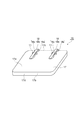
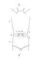
次に、図2〜図4を参照して、検出装置10の物理的な構造例について説明する。図2は、図1に示される検出装置の外観の一例を概略的に示す斜視図である。図3は、図2に示される検出装置の装着例を示す図である。図4は、図3のIV−IV線に沿った断面図である。図2〜図4に示されるように、検出装置10は、筐体17と、取付部材18と、をさらに備えている。
Next, an example of a physical structure of the
筐体17は、扁平な箱型形状を有している。筐体17は、例えば、生体3への安全性の高い材料によって形成されている。筐体17の材料としては、ポリエチレンテレフタレート、及びポリエチレン等が挙げられる。筐体17は、面17a(取付面)、面17b、面17c、及び面17dを有している。面17aは、検出装置10が失禁対策衣類2に装着されている状態で、失禁対策衣類2の内面と対向する面である。面17bは、面17aと反対側の面であって、検出装置10が失禁対策衣類2に装着されている状態で、生体3と対向する面である。面17c,17dは、面17aと面17bとを接続する面である。面17cと面17dとは互いに反対側に位置する。検出装置10の装着時において、面17cは生体3の上半身側を向き、面17dは生体3の下半身側を向く。面17dには、筐体17内にガスを導入するための複数の孔(不図示)が設けられている。
The
筐体17の面17aには、センサ11が設けられている。センサ11は、面17aから突出しており、検出装置10が失禁対策衣類2に装着されている状態で、失禁対策衣類2の内面と接触を成している。センサ11は、面17aの上端部に設けられている。本実施形態では、2つのセンサ11が設けられている。2つのセンサ11は、面17aと面17cとによって形成される端縁の近傍に設けられ、端縁が延びる方向に離間して配置されている。筐体17内には、センサ12〜14、処理部15、通信装置16、不図示の回路基板、及び配線等が収容されている。
The
取付部材18は、筐体17を失禁対策衣類2に取り付けるための部材である。取付部材18は、例えば、生体3への安全性の高い材料によって形成されている。取付部材18の材料としては、ポリエチレンテレフタレート、及びポリエチレン等が挙げられる。取付部材18は、筐体17の面17aに設けられている。本実施形態では、2つの取付部材18が設けられている。2つの取付部材18は、面17aと面17cとによって形成される端縁の近傍に設けられ、端縁が延びる方向に離間して配置されている。取付部材18は、センサ11を覆うように設けられている。
The
各取付部材18は、基部18aと、アーム部18bと、凸部18cと、を備えている。基部18aは、面17aに取り付けられる部分である。基部18aは、面17aと面17cとによって形成される端縁から面17aと離れる方向に延びている。アーム部18bは、基部18aの先端から面17aと略平行に面17dに向かって延びている。アーム部18bは、センサ11上に位置するが、センサ11から離間しており、センサ11に接触していない。アーム部18bとセンサ11との離間距離は、失禁対策衣類2の厚さと同程度である。凸部18cは、アーム部18bの先端に設けられ、面17aに向かって突出している。凸部18cの頂部は、面17aに接触している。
Each mounting
図3及び図4に示されるように、検出装置10は、筐体17が失禁対策衣類2と生体3との間に位置するように、失禁対策衣類2に装着される。この例では、検出装置10は、失禁対策衣類2の腹部側に装着される。具体的には、取付部材18と面17aとの間に、失禁対策衣類2の縁部2aを挿入し、失禁対策衣類2の縁部2aが基部18aと接触を成す程度に検出装置10を生体3の下半身側に押し込む。これにより、凸部18cと面17aとによって、失禁対策衣類2の縁部2aが挟持されて固定される。この状態において、失禁対策衣類2の縁部2aがセンサ11上に位置し、センサ11と接触を成している。このとき、面17aは失禁対策衣類2の腹部側の内面と対向(接触)し、面17bは生体3(腹部3a)と対向(接触)し、面17cは生体3の上半身側に位置し、面17dは生体3の下半身側に位置している。
As shown in FIGS. 3 and 4, the
なお、失禁対策衣類2と生体3との間には空間Vが形成される。生体3が排泄(失禁)した場合には、排泄物から放出されるガスが空間Vに充満する。検出装置10は、面17dから空間V内のガスを筐体17内に導入し、筐体17内に設けられたセンサ12によって、ガスを検出する。
In addition, a space V is formed between the
以上のように、検出装置10では、失禁対策衣類2に取り付けられる筐体17の面17aに、センサ11が設けられている。このセンサ11により、検出装置10が失禁対策衣類2に装着されているか否かの装着状態が検出される。この装着状態を用いることにより、検出装置10が失禁対策衣類2に装着されているか、検出装置10が失禁対策衣類2から外れているかを認識することが可能となる。
As described above, in the
通信装置16は、センサ11で検出された状態値を処理装置30に送信する。このため、処理装置30において、検出装置10が失禁対策衣類2に装着されているか、検出装置10が失禁対策衣類2から外れているかを確認することができる。また、通信装置16は、センサ12〜14で計測された計測値を処理装置30に送信する。通信装置16は無線通信を行うので、処理装置30を生体3から離れた場所に設置することができる。これにより、遠隔地において検出装置10の装着状態、及び生体3の状態を監視することができる。
The
複数のセンサ11のいずれかが、検出装置10が装着されていない(失禁対策衣類2と接触していない)ことを検出することにより、検出装置10が失禁対策衣類2から外れかけている状態を検出することができる。また、センサ11が面17aの中央付近に設けられた場合、センサ11は、検出装置10が失禁対策衣類2から外れかかっていたとしても、検出装置10が失禁対策衣類2に装着されていることを検出するおそれがある。検出装置10では、センサ11は、面17aの面17cとの端縁付近に設けられているので、検出装置10が失禁対策衣類2に対してずれただけでも、センサ11は失禁対策衣類2から離間することがある。このため、検出装置10が失禁対策衣類2から外れかけている状態を精度良く検出することができる。
Any one of the plurality of
高齢者等の監視対象者は、背臥位(仰向け)又は側臥位で就寝することが多い。また、車椅子等を利用している場合には、監視対象者の腰及び背中が背もたれと接触する場合がある。このため、検出装置10が監視対象者の背部3b側に装着されると、監視対象者に違和感を与えるおそれがある。これに対し、筐体17の面17aが失禁対策衣類2の腹部側の内面に取り付けられることによって、検出装置10が監視対象者の腹部3a側に装着される。これにより、監視対象者の違和感を低減することが可能となる。
Monitored persons, such as the elderly, often sleep in a supine (supine) or lateral position. Also, when a wheelchair or the like is used, the waist and back of the monitoring target may come into contact with the backrest. For this reason, if the
また、検出装置10が失禁対策衣類2に正常に装着されている状態において、センサ11は、失禁対策衣類2の縁部2aの内側に位置する。つまり、センサ11は、縁部2aと腹部3aとの間に位置し、縁部2aの内面に接触している。縁部2aは、収縮性を有しているので、縁部2aの内面を生体3(センサ11)に向けて押し付ける。このため、センサ11は、検出装置10が失禁対策衣類2に装着されているか否かをより確実に検出することが可能となる。
In a state where the
センサ11として温度センサが用いられる場合、検出装置10が失禁対策衣類2から外れたことを正確に判定することが困難となることがある。例えば、生体3が布団内で就寝している際に、検出装置10が失禁対策衣類2から外れたとしても、布団内での温度変化は、屋外での温度変化と比較して小さいので、検出装置10が失禁対策衣類2から外れたことを正確に判定することが困難である。一方、センサ11として接触センサが用いられる場合には、センサ11は、検出装置10(筐体17)が失禁対策衣類2と接触しているか否かの接触状態を検出する。このため、布団内で就寝している場合でも、検出装置10が失禁対策衣類2から外れたことを正確に検出することができる。
When a temperature sensor is used as the
なお、本発明に係る検出装置は上記実施形態に限定されない。 Note that the detection device according to the present invention is not limited to the above embodiment.
上記実施形態では、検出装置10は、失禁対策衣類2の腹部側に装着されているが、これに限られない。検出装置10は、失禁対策衣類2の背部側に装着されてもよい。検出装置10が、失禁対策衣類2の腹部側に装着される場合には、筐体17は、生体3の腹部3aを冷やさないように構成されてもよい。例えば、筐体17は、熱伝導率が低い材料で構成されてもよい。また、検出装置10は、面17bを温めるために、化学発熱体又は蓄熱材等を保持してもよい。また、筐体17は、面17bにカイロ等の保温部材を保持可能に構成されてもよい。
In the above embodiment, the
例えば、センサ11の数は、2つに限られない。センサ11の数は、1つでもよく、3つ以上であってもよい。
For example, the number of
また、取付部材18は、筐体17を失禁対策衣類2に取り付け可能な部材であればよい。例えば、取付部材18は、粘着テープでもよく、面ファスナーでもよい。
Further, the
また、検出装置10は、表示装置(出力部)を備えていてもよい。表示装置としては、LED(Light Emitting Diode)、及び液晶ディスプレイ等が用いられてもよい。処理部15は、処理部32によって行われる計測値に基づく判定処理の一部又は全部を行ってもよい。この場合、例えば、表示装置は、検出装置10が失禁対策衣類2に装着されているか否かの装着状態を表示してもよい。また、表示装置は、排泄物の有無を表示してもよい。
In addition, the
また、検出装置10は、センサ11〜14による計測値を一時的に格納するためのメモリを備えていてもよい。メモリとしては、例えば、RAM、及びフラッシュメモリ等の半導体メモリが用いられ得る。処理部15は、センサ11〜14から取得した計測値を計測時刻とともにメモリに一時的に格納してもよい。この場合、検出装置10は、複数の計測時刻における計測値をまとめて処理装置30に送信することができる。また、検出装置10と処理装置30との通信が途絶えた場合に、通信復旧後にメモリに格納されている計測値及び計測時刻を読み出し、通信が途絶えていた間にセンサ11〜14から取得した計測値及び計測時刻を処理装置30に送信することができる。
In addition, the
2…失禁対策衣類、2a…縁部、3…生体、10…検出装置、11…センサ(装着状態検出部)、16…通信装置(出力部)、17…筐体、17a…面(取付面)、18…取付部材、30…処理装置(外部装置)。 2 ... incontinence prevention clothing, 2a ... edge, 3 ... living body, 10 ... detection device, 11 ... sensor (wearing state detection unit), 16 ... communication device (output unit), 17 ... housing, 17a ... surface (mounting surface) ), 18: mounting member, 30: processing device (external device).
Claims (4)
前記失禁対策衣類に取り付けられる取付面を有する筐体と、
前記取付面に設けられ、前記検出装置が前記失禁対策衣類に装着されているか否かの装着状態を検出する装着状態検出部と、
前記装着状態検出部によって検出された前記装着状態を示す状態情報を出力する出力部と、
を備える検出装置。 A detection device attached to incontinence clothing, for detecting excrement,
A housing having a mounting surface to be mounted on the incontinence-preventive clothing,
A mounting state detection unit that is provided on the mounting surface and detects a mounting state of whether the detection device is mounted on the incontinence prevention clothing,
An output unit that outputs state information indicating the wearing state detected by the wearing state detection unit,
A detection device comprising:
Priority Applications (2)
| Application Number | Priority Date | Filing Date | Title |
|---|---|---|---|
| JP2017070897A JP6658656B2 (en) | 2017-03-31 | 2017-03-31 | Detector |
| CN201810011285.7A CN108692762B (en) | 2017-03-31 | 2018-01-05 | Detection device |
Applications Claiming Priority (1)
| Application Number | Priority Date | Filing Date | Title |
|---|---|---|---|
| JP2017070897A JP6658656B2 (en) | 2017-03-31 | 2017-03-31 | Detector |
Publications (2)
| Publication Number | Publication Date |
|---|---|
| JP2018171236A JP2018171236A (en) | 2018-11-08 |
| JP6658656B2 true JP6658656B2 (en) | 2020-03-04 |
Family
ID=63844184
Family Applications (1)
| Application Number | Title | Priority Date | Filing Date |
|---|---|---|---|
| JP2017070897A Active JP6658656B2 (en) | 2017-03-31 | 2017-03-31 | Detector |
Country Status (2)
| Country | Link |
|---|---|
| JP (1) | JP6658656B2 (en) |
| CN (1) | CN108692762B (en) |
Families Citing this family (3)
| Publication number | Priority date | Publication date | Assignee | Title |
|---|---|---|---|---|
| JP2021181884A (en) * | 2018-07-31 | 2021-11-25 | 株式会社aba | Excretion or flatulence detector |
| JP7259700B2 (en) * | 2019-10-30 | 2023-04-18 | 新東工業株式会社 | Determination device and detection device |
| JP7480701B2 (en) | 2020-12-28 | 2024-05-10 | 新東工業株式会社 | Excretion detection device |
Family Cites Families (22)
| Publication number | Priority date | Publication date | Assignee | Title |
|---|---|---|---|---|
| JPH11290407A (en) * | 1998-04-06 | 1999-10-26 | Besu Kogyo Kk | Circulation accelerating apparatus |
| JP2001289806A (en) * | 2000-04-11 | 2001-10-19 | Figaro Eng Inc | Excretion detecting method and apparatus therefor |
| JP2004041697A (en) * | 2003-03-31 | 2004-02-12 | Denso Corp | Urine detection device |
| JPWO2004091400A1 (en) * | 2003-04-11 | 2006-07-06 | 松下電器産業株式会社 | Acceleration sensor axis information correction apparatus and acceleration sensor axis information correction method |
| JP4476052B2 (en) * | 2004-07-06 | 2010-06-09 | 三洋電機株式会社 | Excrement disposal system and diaper |
| WO2006080225A1 (en) * | 2005-01-31 | 2006-08-03 | Hitachi Metals, Ltd. | Fall detecting method and fall detecting device |
| CN101222892B (en) * | 2005-07-11 | 2011-06-29 | Sca卫生产品股份公司 | Method for detecting absorbing articles loosing or falling from body |
| JP2010194277A (en) * | 2009-02-20 | 2010-09-09 | Miinosu Denshi Kk | Diaper monitoring device |
| DE102009049463A1 (en) * | 2009-10-15 | 2011-04-21 | Paul Hartmann Ag | Fixing and carrying device for a disposable absorbent incontinence template |
| CN103040547B (en) * | 2012-12-24 | 2015-01-07 | 中国科学院深圳先进技术研究院 | Portable fall protector |
| CN203252811U (en) * | 2013-04-08 | 2013-10-30 | 医鼎企业有限公司 | Wetting reminding system |
| WO2015004914A1 (en) * | 2013-07-12 | 2015-01-15 | セイコーエプソン株式会社 | Biometric information detection device |
| JP6364747B2 (en) * | 2013-11-14 | 2018-08-01 | オムロン株式会社 | Monitoring device and monitoring method |
| CN104921874A (en) * | 2014-03-20 | 2015-09-23 | 启通科技有限公司 | Wearable paper diaper state monitoring device |
| US10322036B2 (en) * | 2014-10-03 | 2019-06-18 | Glen Haire | Incontinence system |
| TWI572337B (en) * | 2015-03-26 | 2017-03-01 | Urine prompt and test system | |
| KR101686992B1 (en) * | 2015-04-23 | 2016-12-16 | 주식회사 스마트씨솔루션 | Urine sensing device and urine notifying system including the same |
| JP2016214804A (en) * | 2015-05-17 | 2016-12-22 | ミーノス電子有限会社 | Infrared diaper monitoring device |
| CN204833636U (en) * | 2015-08-05 | 2015-12-02 | 深圳五洲无线技术有限公司 | State device is dressed to discernment wearing equipment |
| KR20170024736A (en) * | 2015-08-26 | 2017-03-08 | 손석남 | Diaper the inside relieve oneself light sound inform equipment. |
| CN105943167B (en) * | 2016-04-18 | 2018-08-24 | 深圳市宏电技术股份有限公司 | A kind of wearable device and its wearing state detection device, detection method |
| CN106137145A (en) * | 2016-08-09 | 2016-11-23 | 西安绿野医疗科技有限责任公司 | A kind of intelligent radio body temperature and excretion event detecting sensor |
-
2017
- 2017-03-31 JP JP2017070897A patent/JP6658656B2/en active Active
-
2018
- 2018-01-05 CN CN201810011285.7A patent/CN108692762B/en active Active
Also Published As
| Publication number | Publication date |
|---|---|
| CN108692762A (en) | 2018-10-23 |
| CN108692762B (en) | 2021-12-21 |
| JP2018171236A (en) | 2018-11-08 |
Similar Documents
| Publication | Publication Date | Title |
|---|---|---|
| US7733233B2 (en) | Methods and systems for monitoring position and movement of human beings | |
| US9734690B2 (en) | System and method for activity monitoring and fall detection | |
| CA2677990C (en) | Infant monitor | |
| KR101365591B1 (en) | Body temperature measuring device and system with the same | |
| JP6658656B2 (en) | Detector | |
| US8570175B2 (en) | Securely attachable monitoring device | |
| KR101778637B1 (en) | Wearable device configured in clothing and baby condition notification system using it | |
| US10984646B2 (en) | Proximity based fall and distress detection systems and methods | |
| WO2015135368A1 (en) | Respiratory monitoring device used cooperatively with paper diaper | |
| US20130072763A1 (en) | Mobile Monitoring Device for Monitoring Physical Characteristics of a Subject | |
| US11166855B2 (en) | Diaper sensor device, method and system for diaper surveillance | |
| KR100790000B1 (en) | Multipurpose intelligent mat system for infant and special use | |
| US10182761B2 (en) | Method and system of attachment and detection of attachment of a wearable sensor to clothing material | |
| US9877669B2 (en) | Method and device for monitoring body movement by detecting pattern changes in the distance variations between proximity sensors and their respective sensor zone | |
| AU2014220919A1 (en) | Device for detecting an unhealthy situation of a person lying down, in particular anti-snoring device | |
| JP7259700B2 (en) | Determination device and detection device | |
| JP2019072174A (en) | Detection device | |
| CN217365834U (en) | All-directional nursing device | |
| KR101771036B1 (en) | a multi-function health checking apparatus | |
| KR102377703B1 (en) | Sleep diagnosis device | |
| KR101885902B1 (en) | Thermometer comprising dual temperature sensors | |
| TWI649727B (en) | Non-contact, infant and child, and wearable smart apparatus and the operation method thereof | |
| CN115243611A (en) | Human body motion sensor, program, and information presentation system |
Legal Events
| Date | Code | Title | Description |
|---|---|---|---|
| A621 | Written request for application examination |
Free format text: JAPANESE INTERMEDIATE CODE: A621 Effective date: 20190121 |
|
| A977 | Report on retrieval |
Free format text: JAPANESE INTERMEDIATE CODE: A971007 Effective date: 20191216 |
|
| TRDD | Decision of grant or rejection written | ||
| A01 | Written decision to grant a patent or to grant a registration (utility model) |
Free format text: JAPANESE INTERMEDIATE CODE: A01 Effective date: 20200107 |
|
| A61 | First payment of annual fees (during grant procedure) |
Free format text: JAPANESE INTERMEDIATE CODE: A61 Effective date: 20200120 |
|
| R150 | Certificate of patent or registration of utility model |
Ref document number: 6658656 Country of ref document: JP Free format text: JAPANESE INTERMEDIATE CODE: R150 |
|
| R250 | Receipt of annual fees |
Free format text: JAPANESE INTERMEDIATE CODE: R250 |
|
| R250 | Receipt of annual fees |
Free format text: JAPANESE INTERMEDIATE CODE: R250 |