JP6646050B2 - Non-contact ECG system - Google Patents
Non-contact ECG system Download PDFInfo
- Publication number
- JP6646050B2 JP6646050B2 JP2017516954A JP2017516954A JP6646050B2 JP 6646050 B2 JP6646050 B2 JP 6646050B2 JP 2017516954 A JP2017516954 A JP 2017516954A JP 2017516954 A JP2017516954 A JP 2017516954A JP 6646050 B2 JP6646050 B2 JP 6646050B2
- Authority
- JP
- Japan
- Prior art keywords
- contact
- ecg
- sensor
- contact ecg
- human body
- Prior art date
- Legal status (The legal status is an assumption and is not a legal conclusion. Google has not performed a legal analysis and makes no representation as to the accuracy of the status listed.)
- Expired - Fee Related
Links
Images


Classifications
-
- A—HUMAN NECESSITIES
- A61—MEDICAL OR VETERINARY SCIENCE; HYGIENE
- A61B—DIAGNOSIS; SURGERY; IDENTIFICATION
- A61B5/00—Measuring for diagnostic purposes; Identification of persons
- A61B5/05—Detecting, measuring or recording for diagnosis by means of electric currents or magnetic fields; Measuring using microwaves or radio waves
- A61B5/053—Measuring electrical impedance or conductance of a portion of the body
- A61B5/0537—Measuring body composition by impedance, e.g. tissue hydration or fat content
-
- A—HUMAN NECESSITIES
- A61—MEDICAL OR VETERINARY SCIENCE; HYGIENE
- A61B—DIAGNOSIS; SURGERY; IDENTIFICATION
- A61B5/00—Measuring for diagnostic purposes; Identification of persons
- A61B5/24—Detecting, measuring or recording bioelectric or biomagnetic signals of the body or parts thereof
- A61B5/25—Bioelectric electrodes therefor
- A61B5/279—Bioelectric electrodes therefor specially adapted for particular uses
- A61B5/28—Bioelectric electrodes therefor specially adapted for particular uses for electrocardiography [ECG]
- A61B5/282—Holders for multiple electrodes
-
- A—HUMAN NECESSITIES
- A61—MEDICAL OR VETERINARY SCIENCE; HYGIENE
- A61B—DIAGNOSIS; SURGERY; IDENTIFICATION
- A61B5/00—Measuring for diagnostic purposes; Identification of persons
- A61B5/02—Detecting, measuring or recording pulse, heart rate, blood pressure or blood flow; Combined pulse/heart-rate/blood pressure determination; Evaluating a cardiovascular condition not otherwise provided for, e.g. using combinations of techniques provided for in this group with electrocardiography or electroauscultation; Heart catheters for measuring blood pressure
- A61B5/02028—Determining haemodynamic parameters not otherwise provided for, e.g. cardiac contractility or left ventricular ejection fraction
-
- A—HUMAN NECESSITIES
- A61—MEDICAL OR VETERINARY SCIENCE; HYGIENE
- A61B—DIAGNOSIS; SURGERY; IDENTIFICATION
- A61B5/00—Measuring for diagnostic purposes; Identification of persons
- A61B5/103—Detecting, measuring or recording devices for testing the shape, pattern, colour, size or movement of the body or parts thereof, for diagnostic purposes
- A61B5/11—Measuring movement of the entire body or parts thereof, e.g. head or hand tremor, mobility of a limb
- A61B5/1113—Local tracking of patients, e.g. in a hospital or private home
- A61B5/1114—Tracking parts of the body
-
- A—HUMAN NECESSITIES
- A61—MEDICAL OR VETERINARY SCIENCE; HYGIENE
- A61B—DIAGNOSIS; SURGERY; IDENTIFICATION
- A61B5/00—Measuring for diagnostic purposes; Identification of persons
- A61B5/24—Detecting, measuring or recording bioelectric or biomagnetic signals of the body or parts thereof
- A61B5/25—Bioelectric electrodes therefor
- A61B5/276—Protection against electrode failure
-
- A—HUMAN NECESSITIES
- A61—MEDICAL OR VETERINARY SCIENCE; HYGIENE
- A61B—DIAGNOSIS; SURGERY; IDENTIFICATION
- A61B5/00—Measuring for diagnostic purposes; Identification of persons
- A61B5/24—Detecting, measuring or recording bioelectric or biomagnetic signals of the body or parts thereof
- A61B5/25—Bioelectric electrodes therefor
- A61B5/277—Capacitive electrodes
-
- A—HUMAN NECESSITIES
- A61—MEDICAL OR VETERINARY SCIENCE; HYGIENE
- A61B—DIAGNOSIS; SURGERY; IDENTIFICATION
- A61B5/00—Measuring for diagnostic purposes; Identification of persons
- A61B5/24—Detecting, measuring or recording bioelectric or biomagnetic signals of the body or parts thereof
- A61B5/30—Input circuits therefor
- A61B5/302—Input circuits therefor for capacitive or ionised electrodes, e.g. metal-oxide-semiconductor field-effect transistors [MOSFET]
-
- A—HUMAN NECESSITIES
- A61—MEDICAL OR VETERINARY SCIENCE; HYGIENE
- A61B—DIAGNOSIS; SURGERY; IDENTIFICATION
- A61B5/00—Measuring for diagnostic purposes; Identification of persons
- A61B5/24—Detecting, measuring or recording bioelectric or biomagnetic signals of the body or parts thereof
- A61B5/30—Input circuits therefor
- A61B5/307—Input circuits therefor specially adapted for particular uses
- A61B5/308—Input circuits therefor specially adapted for particular uses for electrocardiography [ECG]
-
- A—HUMAN NECESSITIES
- A61—MEDICAL OR VETERINARY SCIENCE; HYGIENE
- A61B—DIAGNOSIS; SURGERY; IDENTIFICATION
- A61B5/00—Measuring for diagnostic purposes; Identification of persons
- A61B5/24—Detecting, measuring or recording bioelectric or biomagnetic signals of the body or parts thereof
- A61B5/316—Modalities, i.e. specific diagnostic methods
- A61B5/318—Heart-related electrical modalities, e.g. electrocardiography [ECG]
- A61B5/327—Generation of artificial ECG signals based on measured signals, e.g. to compensate for missing leads
-
- A—HUMAN NECESSITIES
- A61—MEDICAL OR VETERINARY SCIENCE; HYGIENE
- A61B—DIAGNOSIS; SURGERY; IDENTIFICATION
- A61B5/00—Measuring for diagnostic purposes; Identification of persons
- A61B5/24—Detecting, measuring or recording bioelectric or biomagnetic signals of the body or parts thereof
- A61B5/316—Modalities, i.e. specific diagnostic methods
- A61B5/318—Heart-related electrical modalities, e.g. electrocardiography [ECG]
- A61B5/339—Displays specially adapted therefor
-
- A—HUMAN NECESSITIES
- A61—MEDICAL OR VETERINARY SCIENCE; HYGIENE
- A61B—DIAGNOSIS; SURGERY; IDENTIFICATION
- A61B5/00—Measuring for diagnostic purposes; Identification of persons
- A61B5/68—Arrangements of detecting, measuring or recording means, e.g. sensors, in relation to patient
- A61B5/6801—Arrangements of detecting, measuring or recording means, e.g. sensors, in relation to patient specially adapted to be attached to or worn on the body surface
- A61B5/6844—Monitoring or controlling distance between sensor and tissue
-
- A—HUMAN NECESSITIES
- A61—MEDICAL OR VETERINARY SCIENCE; HYGIENE
- A61B—DIAGNOSIS; SURGERY; IDENTIFICATION
- A61B5/00—Measuring for diagnostic purposes; Identification of persons
- A61B5/72—Signal processing specially adapted for physiological signals or for diagnostic purposes
- A61B5/7221—Determining signal validity, reliability or quality
-
- A—HUMAN NECESSITIES
- A61—MEDICAL OR VETERINARY SCIENCE; HYGIENE
- A61B—DIAGNOSIS; SURGERY; IDENTIFICATION
- A61B5/00—Measuring for diagnostic purposes; Identification of persons
- A61B5/72—Signal processing specially adapted for physiological signals or for diagnostic purposes
- A61B5/7225—Details of analog processing, e.g. isolation amplifier, gain or sensitivity adjustment, filtering, baseline or drift compensation
-
- A—HUMAN NECESSITIES
- A61—MEDICAL OR VETERINARY SCIENCE; HYGIENE
- A61B—DIAGNOSIS; SURGERY; IDENTIFICATION
- A61B5/00—Measuring for diagnostic purposes; Identification of persons
- A61B5/74—Details of notification to user or communication with user or patient ; user input means
-
- A—HUMAN NECESSITIES
- A61—MEDICAL OR VETERINARY SCIENCE; HYGIENE
- A61B—DIAGNOSIS; SURGERY; IDENTIFICATION
- A61B2562/00—Details of sensors; Constructional details of sensor housings or probes; Accessories for sensors
- A61B2562/02—Details of sensors specially adapted for in-vivo measurements
- A61B2562/0209—Special features of electrodes classified in A61B5/24, A61B5/25, A61B5/283, A61B5/291, A61B5/296, A61B5/053
- A61B2562/0214—Capacitive electrodes
-
- A—HUMAN NECESSITIES
- A61—MEDICAL OR VETERINARY SCIENCE; HYGIENE
- A61B—DIAGNOSIS; SURGERY; IDENTIFICATION
- A61B2562/00—Details of sensors; Constructional details of sensor housings or probes; Accessories for sensors
- A61B2562/04—Arrangements of multiple sensors of the same type
- A61B2562/046—Arrangements of multiple sensors of the same type in a matrix array
-
- A—HUMAN NECESSITIES
- A61—MEDICAL OR VETERINARY SCIENCE; HYGIENE
- A61B—DIAGNOSIS; SURGERY; IDENTIFICATION
- A61B2562/00—Details of sensors; Constructional details of sensor housings or probes; Accessories for sensors
- A61B2562/16—Details of sensor housings or probes; Details of structural supports for sensors
- A61B2562/164—Details of sensor housings or probes; Details of structural supports for sensors the sensor is mounted in or on a conformable substrate or carrier
-
- A—HUMAN NECESSITIES
- A61—MEDICAL OR VETERINARY SCIENCE; HYGIENE
- A61B—DIAGNOSIS; SURGERY; IDENTIFICATION
- A61B5/00—Measuring for diagnostic purposes; Identification of persons
- A61B5/0002—Remote monitoring of patients using telemetry, e.g. transmission of vital signals via a communication network
- A61B5/0004—Remote monitoring of patients using telemetry, e.g. transmission of vital signals via a communication network characterised by the type of physiological signal transmitted
- A61B5/0006—ECG or EEG signals
-
- A—HUMAN NECESSITIES
- A61—MEDICAL OR VETERINARY SCIENCE; HYGIENE
- A61B—DIAGNOSIS; SURGERY; IDENTIFICATION
- A61B5/00—Measuring for diagnostic purposes; Identification of persons
- A61B5/24—Detecting, measuring or recording bioelectric or biomagnetic signals of the body or parts thereof
- A61B5/316—Modalities, i.e. specific diagnostic methods
Landscapes
- Health & Medical Sciences (AREA)
- Life Sciences & Earth Sciences (AREA)
- Engineering & Computer Science (AREA)
- Veterinary Medicine (AREA)
- Pathology (AREA)
- Biophysics (AREA)
- Biomedical Technology (AREA)
- Heart & Thoracic Surgery (AREA)
- Medical Informatics (AREA)
- Molecular Biology (AREA)
- Surgery (AREA)
- Animal Behavior & Ethology (AREA)
- General Health & Medical Sciences (AREA)
- Public Health (AREA)
- Physics & Mathematics (AREA)
- Cardiology (AREA)
- Physiology (AREA)
- Signal Processing (AREA)
- Artificial Intelligence (AREA)
- Psychiatry (AREA)
- Computer Vision & Pattern Recognition (AREA)
- Dentistry (AREA)
- Oral & Maxillofacial Surgery (AREA)
- Microelectronics & Electronic Packaging (AREA)
- Power Engineering (AREA)
- Nuclear Medicine, Radiotherapy & Molecular Imaging (AREA)
- Radiology & Medical Imaging (AREA)
- Measurement And Recording Of Electrical Phenomena And Electrical Characteristics Of The Living Body (AREA)
- Computer Networks & Wireless Communication (AREA)
Description
(関連出願の相互参照)
本出願は、2015年9月23日出願の米国仮特許出願62/054189および2015年8月18日出願の米国仮特許出願62/206542に基づく優先権を請求するものであり、これらの出願の明細書をここに援用するものである。
(Cross-reference of related applications)
This application claims priority from US provisional patent application 62/054189 filed September 23, 2015 and US provisional patent application 62/206542 filed August 18, 2015, which are incorporated herein by reference. The specification is incorporated herein by reference.
(a)分野
本発明は、一般に、心電図システムに関する。
(A) Field The present invention generally relates to an electrocardiogram system.
(b)関連従来技術
心電図(以下ECGという)は、過去の心電図からの変化を強制的に追加テストすることを余儀なくさせる心拍数、不整脈検出、安静時ECG異常の唯一信頼性の高い測定方法である。
(B) Related prior art The electrocardiogram (hereinafter referred to as ECG) is the only reliable method of measuring heart rate, arrhythmia detection, and resting ECG abnormalities that necessitate additional tests for changes from past electrocardiograms. is there.
前記ECGは、多数の心臓性および非心臓性疾患のための医療に使用される基本的な診断および追跡スクリーニングツールの一つである。標準的な12−誘導の心電図は豊富な情報を保持するが、それはデータを10秒間しかキャプチャーしない。複数の誘導で長期モニタリングすれば更に多くの情報が提供され、心電図における変化に対するアクセスが改善される。 The ECG is one of the basic diagnostic and follow-up screening tools used in medicine for a number of cardiac and non-cardiac diseases. While a standard 12-lead ECG holds a wealth of information, it only captures data for 10 seconds. Long-term monitoring with multiple leads provides more information and improves access to changes in the ECG.
長期的モニタリングが欠如していることは複数の理由から重要な医療問題である。患者のファイルに基線心電図が欠如していることによって、しばしば、混乱と、彼らにとってはノーマルであるが、確立した基準によっては異常である、初めてのECGを受けた患者において不必要な追加試験が生じる。多くの場合、たとえ10年前のものであったとしても感知された異常なECGと同じである古いECGが利用可能であるならば、追加の試験は不要となる。言い換えると、現在のECGを過去のものと比較できることは非常に医療上価値があることである。変化が無ければ試験の数が少なくなる。 The lack of long-term monitoring is an important medical problem for several reasons. The lack of baseline ECG in the patient's file often leads to confusion and unnecessary additional testing in patients who have undergone the first ECG, which is normal to them but abnormal by established criteria. Occurs. In many cases, if an old ECG is available that is the same as the abnormal ECG sensed, even if it was ten years old, no additional testing is required. In other words, being able to compare the current ECG to the past is of great medical value. If there is no change, the number of tests will be small.
接触式電極(患者の身体とのガルバニー接続を形成する電極)に依存する従来の心電図測定周波数は、ECGモニタリングが、即座に、非影響的に(unobstrusively)又は頻繁に必要とされる時には問題となる。従来の接触式電極では、正確な位置(したがって、形態(morphology)と信号品質とを確保するために訓練されたヘルスケア提供者が清潔で準備された皮膚表面に配置することが必要とされる。標準的なウェットゲルの接触式電極を配置することの制約として、皮膚の反応を回避するためにそれらの時間制限内にそれらを身体に正確に配置し、それらを取り除くことが含まれる。 Conventional ECG measurement frequencies that rely on contact electrodes (electrodes that form a galvanic connection with the patient's body) are problematic when ECG monitoring is needed immediately, unobstrusively or frequently. Become. Conventional contact electrodes require that a trained health care provider be placed on a clean, prepared skin surface to ensure correct location (and therefore morphology and signal quality). Limitations of placing standard wet gel contact electrodes include accurately placing them on the body and removing them within their time limits to avoid skin reactions.
長期的なモニタリングを提供することができないことに加えて、それらの利用可能性は、以下に記載されるように更に制約を受ける。 In addition to not being able to provide long-term monitoring, their availability is further limited as described below.
理想的には、ECGは、特に、患者が医療上の注意を必要とする症状を有する場合、ルーチン的な医療訪問の一部としてすべての患者に対して行われるべきである。しかしながら、そのテストの利用可能性は限られている。その利用可能性は、ECG機器のコストと、その誘導を患者に対して正しく載置するために患者に対してテストを行うために必要な技師がいないこととによって制限される。ECGのコストに関しては、大半の医師は、そのテストを現場で行うことには投資しない。病院においてさえ、テレメトリユニットは、大きな病院の患者全体に対して集中治療室の外部に位置する約6台〜10台に限定される。 Ideally, an ECG should be performed on all patients as part of a routine medical visit, especially if the patient has symptoms requiring medical attention. However, the availability of the test is limited. Its availability is limited by the cost of the ECG equipment and the lack of a technician needed to test the patient in order to correctly place the guidance on the patient. Regarding the cost of the ECG, most physicians do not invest in conducting the test on site. Even in hospitals, the number of telemetry units is limited to about 6-10 located outside the intensive care unit for the entire patient of a large hospital.
もう一つの欠点は、標準式電極には、ECGの適切で広範囲の利用を制約する複数の問題があることにある。これらの問題は以下のものである。
1.金属、ゲルおよび粘着剤反応によって電極が皮膚と反応するので、このことから入院中に複数回の交換が必要となる。
2.電極を正しく配置するための知識の欠如。
3.電極を配置するための時間。
4.電極が汗、患者の動き、不適切な配置等によって定期的に落ちる場合、等における、モニタリングの延長に関連する諸問題。
5.標準的電極を使用して導出されるECGは筋肉アーチファクトを発生させやすく、それによって虚偽のECGが生じる。
Another disadvantage is that standard electrodes have several problems that restrict the proper and widespread use of ECGs. These problems are:
1. This requires multiple changes during hospitalization as the electrode reacts with the skin due to metal, gel and adhesive reactions.
2. Lack of knowledge to properly position the electrodes.
3. Time to place electrodes.
4. Problems associated with prolonged monitoring, such as when the electrode falls periodically due to sweat, patient movement, improper placement, etc.
5. ECGs derived using standard electrodes are prone to generating muscle artifacts, which results in false ECGs.
別の欠点は、標準電極によって得られる心電図は、労働および材料集約的であることにある。たとえ、一つのテレメトリユニットでも、標準電極を取り付け、再取り付けするために、一人の患者一日当たり看護時間の最大2−3時間もかかりうる。 Another disadvantage is that the ECG obtained with standard electrodes is labor and material intensive. Even with a single telemetry unit, it can take up to 2-3 hours of nursing time per patient per day to attach and reattach standard electrodes.
更に別の欠点は、ECGは、ワイヤとそれらの看護病院スタッフとの接触と電極に対する頻繁な看護的配慮のために、病院での院内感染の拡散源となることにある。 Yet another disadvantage is that ECGs are a source of nosocomial infections in hospitals because of the frequent nursing care for wires and their contact with nursing hospital staff and electrodes.
従って、市場において、上述した欠点に対応するシステムと方法とが求められている。 Accordingly, there is a need in the market for systems and methods that address the above-mentioned shortcomings.
実施形態では、患者の身体上の接触センサのための領域を手作業で識別、準備し、センサをそれらの領域に配置する必要性を無くすることによって、任意の患者又は人から、容易、非影響的かつ迅速に、ECGデータを頻繁かつ低コストでアクセス可能に記録することを可能にするECGシステムを記載する。ここに記載されるシステムは、非接触式であり、毎日又は恒久的に、複数時間のマルチ誘導モニタリングを可能にすることによって、接触式電極に関連する問題を回避するものである。 In embodiments, an area for contact sensors on a patient's body may be easily identified, prepared, and removed from any patient or person by eliminating the need to place sensors in those areas. Described is an ECG system that enables inexpensive and fast recording of ECG data in an accessible and inexpensive manner. The system described herein is non-contact and avoids the problems associated with contact electrodes by allowing multiple hours of multi-inductive monitoring, either daily or permanently.
一つの態様において、非接触式ECGセンサを使用して人体の心電図(ECG)信号を提供するための医療装置(DPMともいう)が提供され、これは、非接触式ECGセンサのアレイから非接触式ECG信号を受け取るように構成された入力部と、前記非接触式ECGセンサアレイの近傍に位置する身体部分の検出、非接触式ECGセンサのグループと各検出された身体部分との関連付け、各グループからの、最高信号品質を有する非接触式ECGセンサの選択、を含む選択処理を行うように構成されるともに、各選択された非接触式ECGセンサの受信された前記非接触式ECG信号に基づいて標準ECG信号を発生するように構成されたプロセッサ、そして前記標準ECG信号を送信するための出力部とを有している。 In one aspect, a medical device (also referred to as a DPM) for providing an electrocardiogram (ECG) signal of a human body using a non-contact ECG sensor is provided, which comprises a non-contact ECG sensor from an array of non-contact ECG sensors. An input configured to receive an expression ECG signal and detecting a body part located near the non-contact ECG sensor array; associating a group of non-contact ECG sensors with each detected body part; Selecting a non-contact type ECG sensor having the highest signal quality from the group, and performing a selection process on the received non-contact type ECG signal of each selected non-contact type ECG sensor. A processor configured to generate a standard ECG signal based thereon; and an output for transmitting the standard ECG signal.
前記医療装置は、2ポンド未満の重量の軽量なポータブル装置として構成することができる。 The medical device can be configured as a lightweight portable device weighing less than 2 pounds.
一実施形態において、前記選択処理は、前記人体の近傍に位置する前記非接触式ECGセンサに関連付けられた前記非接触式ECG信号を使用して前記人体の身体輪郭を得る工程と、前記人体の前記非接触式ECGセンサアレイ上の位置を判定する工程と、前記非接触式ECGセンサをグループに分け、前記人体の前記身体輪郭と前記位置とを利用して各グループを一つの身体部分に関連付ける工程と、各グループから、前記最高品質を有する非接触式ECG信号を提供する前記非接触式ECGセンサを選択する工程、とを更に有する。 In one embodiment, the selection process comprises: obtaining a body contour of the human body using the non-contact ECG signal associated with the non-contact ECG sensor located near the human body; Determining a position on the non-contact ECG sensor array; dividing the non-contact ECG sensors into groups and associating each group with one body part using the body contour and the position of the human body And selecting the non-contact ECG sensor that provides the highest quality non-contact ECG signal from each group.
一実施形態において、前記プロセッサは、各非接触式ECGセンサと前記人体との間のインピーダンスを測定することによって前記人体の近傍に位置する前記非接触式ECGセンサを識別するものとすることができる。 In one embodiment, the processor may identify the non-contact ECG sensor located near the human body by measuring an impedance between each non-contact ECG sensor and the human body. .
別の実施形態において、前記医療装置は、前記非接触式ECGセンサアレイに対する前記人体の動きに追従して所与の身体部分に対して別の非接触式ECGセンサを選択するように構成することができる。更に別の実施形態において、前記プロセッサは、前記別の非接触式ECGセンサの選択工程を行うために、前記選択処理を連続的に再実行するように構成することができる。前記プロセッサは、更に、前記信号品質が所与の閾値を超えて低下した時に、前記選択処理を再実行するべく、各身体部分に関連付けられた前記選択された非接触式ECGセンサの信号品質を連続的にモニタリングするように構成することができる。 In another embodiment, the medical device is configured to follow the movement of the body relative to the non-contact ECG sensor array and select another non-contact ECG sensor for a given body part. Can be. In yet another embodiment, the processor may be configured to continuously re-execute the selection process to perform the step of selecting another non-contact ECG sensor. The processor may further reduce the signal quality of the selected non-contact ECG sensor associated with each body part to re-perform the selection process when the signal quality drops above a given threshold. It can be configured for continuous monitoring.
前記医療装置は、前記非接触式ECG信号から生じる第1標準ECG信号を出力する非接触式モードと、前記非接触式ECG信号と従来の接触式電極から受け取られる従来式ECG信号とから得られる第2標準ECG信号を出力するハイブリッドモードと、従来式接触式電極から受け取られる従来ECG信号から得られる第3標準ECG信号を出力するバイパスモード、とを含む異なる作動モードを有するものとすることができる。 The medical device is derived from a non-contact mode that outputs a first standard ECG signal derived from the non-contact ECG signal, and a conventional ECG signal received from the non-contact ECG signal and a conventional contact electrode. It may have different operating modes including a hybrid mode for outputting a second standard ECG signal and a bypass mode for outputting a third standard ECG signal derived from a conventional ECG signal received from a conventional contact electrode. it can.
前記医療装置は、異なる非接触式ECGセンサ間の相対的インピーダンス差と、各非接触式ECGセンサと前記人体との間の距離又は衣料タイプの違いによる各非接触式ECGセンサと前記人体との間の絶対的インピーダンス、とを制御するように構成された自動利得制御機構を更に備えることができる。 The medical device may further include a relative impedance difference between different non-contact ECG sensors, a distance between each non-contact ECG sensor and the human body, or a difference between each non-contact ECG sensor and the human body due to a difference in clothing type. An automatic gain control mechanism configured to control the absolute impedance between the two.
前記標準ECG信号をデータネットワークを介して遠隔装置に送信するために有線/無線データポートを設けることができる。 A wired / wireless data port may be provided for transmitting the standard ECG signal to a remote device over a data network.
別の態様において、非接触式ECGセンサを使用して人体の心電図(ECG)信号を提供するためのシステムであって、当該システムは、非接触式ECGセンサのアレイを有するセンサパッドと、前記センサに動作可能に接続されるとともに、前記非接触式ECGセンサから非接触式ECG信号を受け取って、前記非接触式ECGセンサアレイの近傍に位置する身体部分を検出する工程と、非接触式ECGセンサのグループを各検出された身体部分に関連付ける工程と、各グループから、最高信号品質を有する非接触式ECGセンサを選択する工程と、を含む選択処理を行うように構成されるとともに、各選択された非接触式ECGセンサの前記非接触式ECG信号に基づいて標準ECG信号を作り出すように構成されたプロセッサと、前記標準ECG信号を送信するための出力部とを有する。 In another aspect, a system for providing an electrocardiogram (ECG) signal of a human body using a non-contact ECG sensor, the system comprising: a sensor pad having an array of non-contact ECG sensors; Receiving a non-contact ECG signal from the non-contact ECG sensor and detecting a body part located in proximity to the non-contact ECG sensor array; and a non-contact ECG sensor Is associated with each detected body part, and selecting a non-contact ECG sensor having the highest signal quality from each group. A processor configured to generate a standard ECG signal based on the non-contact ECG signal of the non-contact ECG sensor; And an output unit for transmitting a quasi ECG signal.
一実施形態において、前記センサパッドは、前記人体の近傍でかつ人体から離間して配置するための接地パッドを有し、当該接地パッドは、干渉を低減するために前記人体に対する容量結合接地基準を提供するように構成されている。 In one embodiment, the sensor pad has a ground pad for placement near and away from the human body, wherein the ground pad defines a capacitively coupled ground reference to the human body to reduce interference. It is configured to provide.
別の実施形態において、前記接地パッドは、前記非接触式ECG信号から導出されるフィードバック信号によって駆動することができる。 In another embodiment, the ground pad can be driven by a feedback signal derived from the non-contact ECG signal.
前記システムは、各非接触式ECGセンサに対して前記容量結合接地基準を決定するためにECG周波数帯域外の高周波数信号を前記接地パッドに供給するように構成された駆動信号発生器を更に備えることができる。 The system further includes a drive signal generator configured to provide a high frequency signal outside an ECG frequency band to the ground pad to determine the capacitively coupled ground reference for each non-contact ECG sensor. be able to.
一実施形態において、前記非接触式ECGセンサは、前記人体に容量結合されて、心臓の電気的活動を表す電荷を出力するように構成された容量電極と、前記容量電極によって作り出された前記電荷を検出し増幅するように構成されたエレクトロダイナミックセンサと、前記エレクトロダイナミックセンサの入力部の浮遊干渉を低減するために前記電極の近傍に物理的に設けられた電極シールドとを備えることができる。 In one embodiment, the non-contact ECG sensor is capacitively coupled to the human body and configured to output a charge representative of electrical activity of the heart, and the charge generated by the capacitor electrode. And an electrode shield physically provided near the electrode to reduce stray interference at the input of the electrodynamic sensor.
前記非接触式ECGセンサは、フレキシブル材から形成することができる。 The non-contact ECG sensor can be formed from a flexible material.
一実施形態において、前記センサパッドは、前記人体が接触する生地に設けることができる。 In one embodiment, the sensor pad may be provided on a fabric with which the human body contacts.
別の態様において、非接触式ECGセンサを用いて人体の心電図(ECG)信号を提供する方法が提供され、当該方法は、非接触式ECGのアレイから非接触式ECG信号を受け取る工程と、前記非接触式ECGセンサアレイの近傍に位置する身体部分を検出する工程と、非接触式ECGセンサのグループを各検出された身体部分と関連付ける工程と、最高信号品質を有する非接触式ECGセンサを、各グループから選択する工程と、各選択された非接触式ECGセンサの前記非接触式ECG信号に基づいて標準ECG信号を作り出す工程とを有する。 In another aspect, there is provided a method of providing an electrocardiogram (ECG) signal of a human body using a non-contact ECG sensor, the method comprising the steps of: receiving a non-contact ECG signal from an array of non-contact ECG; Detecting a body part located in proximity to the non-contact ECG sensor array; associating a group of non-contact ECG sensors with each detected body part; and a non-contact ECG sensor having the highest signal quality. Selecting from each group and generating a standard ECG signal based on the non-contact ECG signal of each selected non-contact ECG sensor.
前記方法は、前記人体の近傍に位置する前記非接触式ECGセンサに関連付けられた前記非接触式ECG信号を使用して前記人体の身体輪郭を得る工程と、前記人体の前記非接触式ECGセンサアレイ上の位置を判定する工程と、前記非接触式ECGセンサをグループに分け、前記人体の前記身体輪郭と前記位置とを利用して各グループを一つの身体部分に関連付ける工程と、各グループから、前記最高品質を有する非接触式ECG信号を提供する前記非接触式ECGセンサを選択する工程、とを更に有する。 The method comprises: obtaining a body contour of the human body using the non-contact ECG signal associated with the non-contact ECG sensor located in proximity to the human body; and the non-contact ECG sensor of the human body Determining a position on the array; grouping the non-contact ECG sensors into groups; utilizing the body contour and the position of the human body to associate each group with one body part; Selecting the non-contact ECG sensor that provides the highest quality non-contact ECG signal.
一実施形態において、前記方法は、各非接触式ECGセンサと前記人体との間のインピーダンスを測定することによって前記人体の近傍に位置する前記非接触式ECGセンサを識別する工程を更に有する。 In one embodiment, the method further comprises identifying the non-contact ECG sensor located near the human body by measuring an impedance between each non-contact ECG sensor and the human body.
前記方法は、更に、前記非接触式ECGセンサアレイに対する前記人体の動きに追従して、所与の身体部分に対して別の非接触式ECGセンサを選択するために、前記検出工程から前記選択工程を連続的に反復することができる。一実施形態において、各身体部分に関連付けられた前記選択された非接触式ECGセンサの信号品質を連続的にモニタリングして、前記非接触式ECGセンサアレイに対する前記人体の動きに追従して、信号品質が所与の閾値を超えて低下した時に、所与の身体部分に対して別の非接触式ECGセンサを選択するために前記検出工程から前記選択行程を反復することが可能である。 The method further comprises following the movement of the human body with respect to the non-contact ECG sensor array to select another non-contact ECG sensor for a given body part from the detecting step. The process can be repeated continuously. In one embodiment, the signal quality of the selected non-contact ECG sensor associated with each body part is continuously monitored to follow the movement of the human body relative to the non-contact ECG sensor array, When the quality drops above a given threshold, the selection process can be repeated from the detection step to select another non-contact ECG sensor for a given body part.
下記の用語を次のように定義する。 The following terms are defined as follows:
前記誘導という用語は、PQRSTU波形を提供し示す人体上の二つの位置の間の測定電圧の差を意味するものとする。 The term lead shall mean the difference between the measured voltages between two locations on the human body that provide and show the PQRSTU waveform.
前記ECG誘導という用語は、人体上の二つの医学的に定義される位置の間の測定電圧の差に基づく医学的に定義されたECG信号を意味するものとする。 The term ECG derivation is intended to mean a medically defined ECG signal based on the difference in measured voltage between two medically defined locations on the human body.
標準ECG信号は、既存の医療機器とインターフェースし、ECG標準に適合するECG信号である。標準ECG信号は、単一のリズムストリップ又は、任意の数の標準の医学的に定義されたECG誘導を含むことができる。 A standard ECG signal is an ECG signal that interfaces with existing medical equipment and conforms to the ECG standard. The standard ECG signal can include a single rhythm strip or any number of standard medically defined ECG leads.
リズムストリップは、前記PQRSTU波形間のリズムを示す任意の誘導である。前記リズムストリップは、前記ECG信号が前記医学的定義されたECG位置から採取されるものであることを要件としない。 A rhythm strip is any lead that indicates the rhythm between the PQRSTU waveforms. The rhythm strip does not require that the ECG signal be taken from the medically defined ECG location.
添付の図面に図示されている、選択された実施形態の以下の詳細説明を参照することによって本発明の特徴および利点はより明らかになるであろう。理解されるように、ここに開示されクレームされる発明は、請求項の範囲から逸脱することなく、様々な点において改造が可能である。従って、これらの図面および説明は、本来的に例示的なものと見なされるべきであって、限定的なものと見なされてはならず、本発明の完全な範囲は請求項に記載されている。 The features and advantages of the present invention will become more apparent with reference to the following detailed description of selected embodiments, as illustrated in the accompanying drawings. As will be realized, the invention disclosed and claimed herein can be modified in various respects without departing from the scope of the claims. Accordingly, these drawings and descriptions should be regarded as illustrative in nature and not as restrictive, and the full scope of the invention is set forth in the following claims. .
本開示のその他の特徴および利点は、添付の図面を参照して、以下の詳細説明から明らかになるであろう。 Other features and advantages of the present disclosure will become apparent from the following detailed description, taken in conjunction with the accompanying drawings.
尚、これら添付の図面全体を通じて、同様の特徴構成は類似の参照番号で示されている。 It should be noted that like features are indicated by like reference numerals throughout the accompanying drawings.
既存の医療機器への出力(更に、新規/専用モニタへの出力、又は、計算装置と連動するディスプレイ装置上でのビューイング)のため、或いは、遠隔/ローカル装置上での保存又はビューイングのために非接触式ECGセンサを用いて人体の標準心電図(ECG)信号を提供するシステムである。当該システムは、生地等に設けられた非接触式ECGセンサのアレイに接続されるように構成されたデジタル処理モジュール(DPM)を有する。前記DPMには、当該DPMが、異なるECGセンサのECG信号を使用して身体部分を識別し、各身体部分に対して、最善のセンサ誘導を選択することを可能にするための選択機構が組み込まれている。これにより、前記DPMは、検出された異なる身体部分に対して選択されたECG信号を使用して前記標準ECG信号を作り出すことができる。前記システムは、前記身体部分の動きに追従して所与の身体部分に対して最善な誘導が選択されることを保証するために前記選択を連続的に再検査し、それによって患者の連続的で中断されないECGモニタリングを可能にするように構成されている。 For output to existing medical equipment (and output to a new / dedicated monitor, or viewing on a display device in conjunction with a computing device) or for storage or viewing on a remote / local device Is a system for providing a standard electrocardiogram (ECG) signal of a human body using a non-contact ECG sensor. The system includes a digital processing module (DPM) configured to be connected to an array of non-contact ECG sensors provided on a fabric or the like. The DPM incorporates a selection mechanism that allows the DPM to identify body parts using ECG signals of different ECG sensors and to select the best sensor guidance for each body part. Have been. This allows the DPM to create the standard ECG signal using the ECG signal selected for different detected body parts. The system continuously re-examines the selection to follow the movement of the body part and ensure that the best lead is selected for a given body part, thereby ensuring that the patient And configured to allow uninterrupted ECG monitoring.
本発明の範囲を限定するのではなく、それを例示するために提供される下記の例を参照することによって本発明はより良く理解されるであろう。 The invention will be better understood by reference to the following examples, which are provided to illustrate, but not limit, the scope of the invention.
次に図面を参照すると、図1は、一実施形態による例示的ECGシステム200のブロック図である。図1に図示されているように、前記システム200は、(非限定的具体例では)センサパッド7に設けられた非接触式センサのアレイと、当該センサアレイに動作可能に接続され、ケーブル9を使用して前記パッド7に設けられた前記センサからのセンサ読み取り値を得るデジタル処理モジュール(DPM)2とを有する。当該DPM2は、心臓の電気生理学的活動(体表面電位マップ)を記録し、同時に、前記既存医療機器(6)へ標準ECG信号(+前胸部後方(+posterior precordials))を出力するために最善の電極/センサを識別するように構成することができる。前記DPMは、データを医師に対して容易にリアルタイムで入手可能とし医師がDPM2によって検出された不整脈および虚血性変化を迅速に診断できるようにインターネット又はデータネットワークを介してモバイル装置(3)又はクラウド(4)に接続することができる。
Referring now to the drawings, FIG. 1 is a block diagram of an
非限定的例において、前記DPM2は、重量が約2ポンド以下で、前記連続ECGモニタリング行うために持ち運び可能な軽量なポータブル医療装置として提供することができる。 In a non-limiting example, the DPM2 can be provided as a lightweight portable medical device weighing less than about 2 pounds and portable for the continuous ECG monitoring.
上述したように、前記DPM2は、その出力信号が標準接触式ECGシステムによって得られるものと同じものとなって、既存の医療機器6をプラグ・アンド・プレー式に使用してビューイング/読み取りが可能となるように(それによってDPMから受け取られる前記標準ECG信号を読み取って出力するために前記既存医療機器に対してなんら変更を加えることがない)、既存の医療標準に準拠する信号を作り出すように構成することができる。前記DPM2は、既存の医療機器6を使用して同時に読み取り可能な信号を出力するための標準ケーブル(8)を受け入れるように構成されたデータ出力プラグを備えることができる。前記DPM2は、更に、もしも標準中継ケーブル5が取り付けられた場合に接触式ECG情報を同時に記録することが可能なように構成することもできる。
As described above, the output signal of the
但し、前記DPM2は、それ自身のディスプレイ装置を内蔵したり、或いは、それに連動されるように構成したり、前記標準ECG信号をローカル/遠隔パーソナルコンピュータ又はポータブル装置上で利用可能とするべく通信/データネットワークを介して前記標準ECG信号を送信/ストリーミングするように構成することも可能である。
However, the
尚、図1は非限定的例を図示するものであることが銘記される。請求項に定義されている本発明の範囲から逸脱することなく前記システム200に対して改造が可能である。例えば、図1は、異なるモジュール間でデータを通信するためのケーブルを図示しているが、Wi−Fi、Bluetooth等を含め、但しそれらに限定されることなく、無線接続を使用することも考えられる。
It is noted that FIG. 1 illustrates a non-limiting example. Modifications to the
更に、前記センサアレイは、衣服、ベッドおよび車両装置/コンポーネントを含むその他さまざまな物体に設けることができる。別の例において、前記センサアレイは、家具(たとえば、椅子、ベッド/マットレス/カバー、ソファー、シート、マットレス)、車載装置(たとえば、ヘッドレスト、ハンドル等)、ウェアラブルデバイス(たとえば、ジャケット、シャツ、Tシャツ、セーター、ブラジャー等)を含むがそれらに限定されない複数の装置に設けることができる。 Further, the sensor array may be provided on a variety of other objects, including clothing, beds, and vehicle equipment / components. In another example, the sensor array includes furniture (eg, chairs, beds / mattresses / covers, sofas, seats, mattresses), in-vehicle devices (eg, headrests, handles, etc.), wearable devices (eg, jackets, shirts, T-shirts, etc.). Shirts, sweaters, brassiere, etc.).
<選択アルゴリズム>
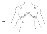
従来のECGでは、患者の生理機能に基づいて電極位置が決まり、それによって、従来の接触式電極は、これらの位置に付着され、患者の動きに拘らず相対的な身体位置を維持する。例えば、図11に例示されているように、V1電極は、胸骨の右側の第4肋間腔に配置されるべきであり、RA電極は、右腕に配置されるべきであり、LA電極はRAと同じ位置であるが、左腕に配置されるべきであり、RL電極は、右脚、側方腓腹に配置すべてきである、等々。これらの電極とそれらの位置との重要性は、二つの特定の位置の間の電圧差が、医学的に定義されるECG誘導を表し(図11および12に関して記載されるように)、心電図の誘導は、それに沿って心臓の脱分極が測定され記録されて心電図が作り出されるベクトルを表すという事実にある。
<Selection algorithm>
In a conventional ECG, electrode positions are determined based on the physiology of the patient, whereby conventional contact electrodes are attached to these positions to maintain a relative body position regardless of patient movement. For example, as illustrated in FIG. 11, the V1 electrode should be placed in the fourth intercostal space on the right side of the sternum, the RA electrode should be placed in the right arm, and the LA electrode should be The same location but should be placed on the left arm, the RL electrode should be placed on the right leg, lateral calf, etc. The importance of these electrodes and their location is that the voltage difference between two specific locations represents a medically defined ECG lead (as described with respect to FIGS. 11 and 12) and The lead consists in the fact that the depolarization of the heart is measured and recorded along with the fact that the electrocardiogram is created representing a vector.
従って、従来のECG標準に適合するECG信号を作り出すためには、データは非接触式に収集されるが、同じ原理に従うことが必要である。 Thus, in order to produce an ECG signal that conforms to the conventional ECG standard, the data is collected contactlessly, but must follow the same principles.
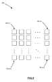
図2は、実施形態によるセンサマトリクス200の非限定的例を図示している。図2に図示されているように、前記マトリクス200は、マトリクス配置されたセンサ10のn個の列、m個の行を有し、これにより、患者がこのマトリクス200上でいかに位置しようとも、従来式ECG電極の物理的配置に対応する患者の身体上の位置に少なくとも1つのセンサが常に存在するように構成されている。前記DPM2に組み込まれた適応アルゴリズムを使用して、患者の身体上の所定のECG位置に対応する所与のセンサ10を前記マトリクス200が選択することによって連続的ECG読み取り値を得ることができる。
FIG. 2 illustrates a non-limiting example of a
図3は、一実施形態による、前記選択アルゴリズム204によって実行される主要な工程を示すフローチャートである。工程210において、前記アルゴリズムは、各センサ10と患者との間のインピーダンスを測定することによってどのセンサ10が患者の身体の近傍にあるかを検出する。これによって、そこからデータを得るために使用可能なセンサ10の検出が可能となる。次に、患者の身体輪郭を得るために、これらのセンサ10(身体の近傍にあると判定されるもの)によって出力されるECG信号を分析する。
FIG. 3 is a flowchart illustrating the main steps performed by the
非限定的具体例において、前記実施形態は、身体輪郭を得るために異なるタイプの情報を利用することができる。第1のタイプは、身体とセンサとの間の距離を表す結合インピーダンスである。結合インピーダンスが高すぎる場合は、センサは身体から離れすぎており、使用することができない。第2のタイプは、その信号自身、たとえば、信号の形態と、いかにその信号が通常のECGパターンを有するように見えるか否か(PQRSTU波形)である。第3のタイプの情報は、良好なECG信号を提供するECGセンサの幾何学的位置である。これらのセンサとそれらの位置とによって、図13aと13bとに例示されているように、人体の幾何学的形状に関する指示が提供される。図13aの例において、ユーザ250がセンサパッド202が埋め込まれたマットレスに横たわっていると仮定すると、この患者の身体の近傍にあるセンサ10aが良好なECG信号を得るのに対して患者の身体の外側にあるセンサ10bは、良好な信号を得ない。この情報と、前記パッド202上の各センサの位置とに基づき、前記DPM2は、患者身体の輪郭252を得ることができ、ここから、前記DPM2は、図13bに例示されているように、患者身体の形状、幅、その他の寸法を得ることができる。次に、この情報と、前記DPM2に組み込まれた規則セットとを使用して、前記DPM2は、身体部分の位置を検出/判定し、下記するように、ECG目的のために、単数又は複数のセンサ10を各身体部分/身体位置と関連付けることができる。
In a non-limiting example, the embodiments can utilize different types of information to obtain body contours. The first type is a coupling impedance that represents the distance between the body and the sensor. If the coupling impedance is too high, the sensor is too far from the body and cannot be used. The second type is the signal itself, eg, the form of the signal, and how the signal appears to have a normal ECG pattern (PQRSTU waveform). The third type of information is the geometric location of the ECG sensor that provides a good ECG signal. These sensors and their locations provide an indication as to the geometry of the human body, as illustrated in FIGS. 13a and 13b. In the example of FIG. 13a, assuming that the
工程212において、前記アルゴリズムは、前記センサから受け取ったECG信号を分析し、これを既に検出済みである身体輪郭と組み合わせて、前記パッド上の患者身体の位置を見出す。工程214において、前記アルゴリズムは、身体上のどこに各センサ10が位置しているかのマッピングを工程210および212から得た前記情報を利用して行う。センサのグループがECG目的の各主要な身体部分(右腕、左腕、等)の近傍に見出されると、工程216において、これらの隣接するセンサからの信号を比較、フィルタリングして、前記各身体部分に対してECGデータを受け取って記録するための最善のECG信号を有する単一のセンサを選択する。
In
一実施形態において、前記DPM2は、患者の動きを常に考慮に入れるべく前記最善のECG読み取り値を有する前記センサ10の選択を再検証し、それによってその動きの前に選択されたものよりも良好な読み取り値を有する新たなセンサ10を選択可能とするべく前記センサ10から得られた読み取り値をリアルタイムで再検査するために前記選択アルゴリズム204を連続的かつ動的に実行するように構成することができる。
In one embodiment, the
別の実施形態において、前記システムは、患者が動いた時を検出すると共に、新たな選択を行う必要があるか否かを再度計算するために前記アルゴリズムを再び実行することが必要な時を判断する。例えば、前記システムは、前記信号の強度/品質をモニタリングし、前記信号品質が所定の閾値以下に低下した時に前記選択アルゴリズム204を再実行するように判断することができる。
In another embodiment, the system detects when the patient moves and determines when the algorithm needs to be run again to recalculate whether a new selection needs to be made. I do. For example, the system may monitor the signal strength / quality and determine to re-execute the
<PQRSTU波形の検出>
上述したように、前記システムは、心臓電気生理学的活動とECGとを記録するように構成することができる。具体的には、前記システムは、一実施形態によるシステムを使用して患者から得られた全PQRSTU波形の具体例を図示する図4に例示されているように、前記PQRSTUスペクトル構成ECG波形を得るように設計することができる。図4に図示されている前記PQRSTU波形は、心臓によって発生され、診断のために医師によってビューイングされるべく前記システムによって捕捉される。一実施形態において、前記システムは、前記ECG読み取り値を獲得し、これらを処理して既存の医療機器によって読み取り、ビューイングが可能なECG信号を作り出すと共に、標準的な接触式ECGシステムによって作り出されるものと同じであって、従って、すべての用途のために標準式ECGシステムの代わりに使用可能である波形を作り出す。
<Detection of PQRSTU waveform>
As described above, the system can be configured to record cardiac electrophysiological activity and ECG. Specifically, the system obtains the PQRSTU spectral composition ECG waveform as illustrated in FIG. 4, which illustrates a specific example of a total PQRSTU waveform obtained from a patient using the system according to one embodiment. Can be designed as follows. The PQRSTU waveform illustrated in FIG. 4 is generated by the heart and captured by the system to be viewed by a physician for diagnosis. In one embodiment, the system obtains the ECG readings and processes them to produce an ECG signal that can be read and viewed by existing medical devices and produced by a standard contact ECG system. Creates a waveform that is the same as that, and thus can be used in place of a standard ECG system for all applications.
勿論、前記非接触式センサ10は、既存の医療機器(たとえば、モニタ等)と互換性のある出力を作り出すものではなく、従って、これらの機器とインターフェースすることは不可能であって、それ故、更なる処理を必要とする。一実施形態において、前記DPMは、獲得された信号を、既存の医療機器のための国際基準に準拠するフォーマットに変換する。これによって、既存の診断医療装置を交換する必要なく、又は、医師および医療従事者を再訓練する必要なく、従来の接触式ECGシステムのシームレスな交換が可能となる。このような変換は、デジタル信号処理と、D/A変換段階(19)においてアナログ出力回路との組み合わせを利用して前記DMS2において行うことができる。
Of course, the
<センサ構成>
上述したように、前記実施形態は、非接触式ECGセンサ10を利用して患者のECG読み取り値を得る。これらセンサ10は、具体的には、患者の皮膚との直接的な電気的接触無く、患者から高品質のECGを捕捉するように特に構成されている。これによって、たとえば、いかにして前記センサアレイが患者の皮膚と直接的に接触することなくECG信号を捕捉するかの具体例を図示する図5に例示されているように、前記センサ10を、患者から距離を置いて、および/又は、衣服や寝具、等の生地を介して患者の身体から分離して配置することが可能となる。
<Sensor configuration>
As described above, the embodiment utilizes the
図6は、一実施形態による例示的センサ構成を図示するブロック図である。この図6に図示されているように、前記センサ10は、導電性電極33と、電極シールド32と、増幅器34とバイアス回路35電圧とを含むエレクトロダイナミックセンサとを備えることができる。図6の例示構成において、前記利得/電流緩衝増幅器34をネガティブフィードバックトポロジーに使用することができ、入力バイアスネットワーク35は、獲得したECGの信号品質を保持するために前記増幅器34の有効入力インピーダンスを増大させるように構成される。前記エレクトロダイナミックセンサの入力は、前記導電性電極33に接続される。前記エレクトロダイナミックセンサの入力に見られる寄生キャパシタンスを低減することによってS/N比(SNR)を更に増大するべく前記電極シールド(32)に接続されるフィードバック信号を発生するためにシールド駆動回路(36)を使用することができる。
FIG. 6 is a block diagram illustrating an exemplary sensor configuration according to one embodiment. As shown in FIG. 6, the
前記電極33は、皮膚/身体の近傍にあるが、それに触れないことによって患者の身体に対して容量結合することができる。これは、着服したままで、(非限定的具体例として)センサ10のアレイを埋め込んだベッドに横たわることによって達成することができる。心臓の電気活動から作り出される患者の皮膚の近傍の電界によって直接的に電気接触することなく前記導電性電極33上に電荷が容量的に誘導される。その後、この電荷を前記エレクトロダイナミックセンサによって収集増幅することができ、これがその位置での心臓の電気的活動(完全なPQRSTU)を表す電気信号(電圧)を作り出す。
The
前記電極シールド32は。前記エレクトロダイナミックセンサが受ける浮遊干渉の量を低減するとともに、前記増幅器34の入力における有効キャパシタンスを減少させ、それによって前記獲得ECGの信号品質を保持することに役立つように構成されている。
The
非限定的具体例において、前記電極33と前記電極シールド32との両方を、前記センサ10が人体の幾何学的形状によりよく適合して、より良好なECG読み取り値を得ることを可能にする弾性/フレキシブル材から形成することができる。同時に、この構成によって、前記センサ10を、その内部で前記センサアレイが配置される生地(又は、ゲル/シリコーン/ゴムタイプのパッド/マット、等)にシームレスに設けることが可能となる。
In a non-limiting embodiment, both the
図7は、前記センサ10の物理的構造の一例を図示している。図7に例示されているように、この物理的構造は、層39として物理的に実施される前記導電性電極33と、前記層40として物理的に実施される前記シールド32と、前記層41に埋め込まれた前記回路の残り部分とを含む。前記構造全体を、たとえば、プリント回路基板とすることが可能な基材37上に形成することも可能である。図7に図示されている構成において、前記層39,40,41は、絶縁層38によって互いに絶縁されて電気的絶縁を提供することができる。
FIG. 7 illustrates an example of a physical structure of the
図8は、実施形態によるシステムの全体構成の例示的ブロック図を示している。 FIG. 8 is an exemplary block diagram of the overall configuration of the system according to the embodiment.
図8を参照すると、そして、図1に関して上述したように、前記システムは、図2に図示されているもののようなアレイ202の形状で設けることが可能な非接触式ECGセンサ(以後、CECGセンサ10と称する)を含むセンサパッド7を備えることができる。当該センサパッド7は、更に、接地パッド15と、駆動回路、たとえば、右脚駆動(RLD)発生器14(後述する)と、A/Dコンバータ13とを備えることができる。前記センサパッド7は、前記センサ10のデジタル化されたECG読み取り値を前記DPM2に出力する。前記RLD発生器14は、前記接地パッド15に、前記ECG周波数帯域外高周波信号を供給するように構成されている。この高周波信号は、その後、患者の身体を介して前記CECGセンサに結合され、ここで、その振幅が前記DPM2によって記録され分析される。これによって、システムに対して、各センサが患者に対していかに良好に結合されるか、各センサからの信号品質がどのようなものなのかを判断するためのインピーダンス測定、メトリックが提供される。
Referring to FIG. 8, and as described above with respect to FIG. 1, the system includes a non-contact ECG sensor (hereinafter a CECG sensor) that can be provided in the form of an
前記デジタル化されたCECGセンサデータの他に、前記DPM2は、更に、従来式電極のアナログ形態の標準ECGデータを受け取るようにも構成することができる。そのようなアナログ式ECGデータは、オプションとして、標準接触式電極と中継ケーブル(5)とを使用することによって獲得される。前記アナログ信号は、ADC17を使用して変換することができる。次に、前記信号は、デジタル信号処理ユニット18を使用してフィルタリングすることができ、様々な有線および無線インターフェースを介して出力される(Wi−Fi(22)/イーサネット(23)を介してモバイルアプリ(3)/クラウドサーバ(4)へと出力され、および「アナログCECG&ECG出力」インターフェースを介して既存の医療機器(6)へと出力される。)。
In addition to the digitized CECG sensor data, the
前記DPM2は、ECGデータの保存のために(必要な場合)なんらかの非揮発性メモリ、たとえば、フラッシュメモリ26を備えることができる。前記DPM2は、更に、急性の問題のための診断を実行し、前記通信インターフェースのいずれかを介して、又は内蔵の音声アラーム(24)によって警告を送るように構成することも可能である。前記DPM2は、更に、ユーザによってモバイル装置を介した設定を可能にするためにブルートゥースローエナジーインターフェース(21)を備えることも可能である。固有識別子を格納するために、読み取り専用メモリ(25)を設けることも可能である。前記通信インターフェースを介して送信/受信されるデータを暗号化および復号化し、このデータの暗号化のためのキーを安全に記憶しておくために暗号処理モジュール(27)を設けることも可能である。
The
全てのセンサデータ(非接触式と接触式)を前記有線および無線インターフェースを介して送信することができる。(図3において上述した)前記選択アルゴリズム204は、どのセンサ情報を前記アナログインターフェース19を介して既存医療機器に出力すべきかを判定する。前記従来式電極から受け取られるアナログデータと前記非接触式センサ10間を切り替え、前記DPM2がこれらの二つを比較することを可能にするためのリレー20を設けることができる。DPM2を、所望の場合、前記接触ECG信号に影響を与えることなく、パススルーケーブル等のように作用するために作動停止するように構成することができる(前記処理ユニットとリレー(20)とによって制御される)。それは、又、「ハイブリッドモード」で作動することもでき、このモードでは、もしもそれによって前記ECG信号の品質が改善させるのであればCECGとECGセンサとの組み合わせを、前記アナログインターフェースを介して出力することができる。
All sensor data (non-contact and contact) can be transmitted via the wired and wireless interfaces. The selection algorithm 204 (described above in FIG. 3) determines which sensor information is to be output to the existing medical device via the
<自動利得補正>
前記電気生理センサの大きな、但し有限である入力インピーダンスにより、各センサ10と患者の身体との間の容量結合における変動(たとえば、各センサと身体との間の距離の変化)によって各センサチャネルの利得の変動を引き起こす可能性がある。これは、完全に乾燥した接触粘着性電極が新しい電極よりも低質な信号を作り出すのと同様に、ECG誘導の振幅に影響を与える作用を有する。この問題に対応するために、前記システムが異なる非接触式ECGセンサ間の相対的インピーダンス差と、各非接触式ECGセンサと人体との間の距離の差による各非接触式ECGセンサと人体との間の絶対的インピーダンスとを制御することを可能にする利得制御機構が設けられる。図9に図示されているように、前記センサ10と患者との間の結合の差によって引き起こされる利得の変化をオフセットするために各センサチャンネル42にプログラマブル利得増幅器43(アナログ式又はデジタル式)が設けられる。図9は、一実施形態による例示的な利得制御機構を図示するブロック図である。図9に図示されているように、前記利得制御機構220は、前記PGA43と、前記変化が生じている時にその利得をリアルタイムで制御するためにそれ自身が前記PGA43に接続されているプロセッサ45との間に結合されたADC44を含むフィードバックループを備えることができる。
<Automatic gain correction>
Due to the large, but finite input impedance of the electrophysiological sensor, variations in the capacitive coupling between each
前記プロセッサ45は、専用のプロセッサであってもよいし、或いは、前記DPM2の処理ユニット18に組み込まれたプロセッサモジュールであってもよい。
The
<右脚ドライブ>
図8に戻ると、作動時においては、患者の身体の近くで、但し、接触はしない(距離がある)状態で配置されるべき接地パッド15が図示されている。このパッドは、前記ECG信号から導出されるフィードバック信号によって駆動されて、患者の身体に対する容量結合接地基準を提供する。前記フィードバック信号は、前記システムのコモンモード除去比(CMRR)を増大させる(通常は、10dB以上)ように導出される。これによって、コモンモード信号からの干渉が低減され、獲得ECGの信号品質が保持される。
<Right leg drive>
Returning to FIG. 8, there is shown the
図10は、一実施形態による前記RLD発生器14の機能を図示する例示的ブロック図である。図10に図示されているように、前記センサから受け取られたデータは、前記処理ユニット(18)においてデジタルで実行されるRLDアルゴリズムを使用して、データを得るための特定のセンサ10を選択するスイッチングマトリクス(29)を使用して選択される(又は切り捨てられる)。次に、これらの信号を合計し(29)、反転し増幅する(30)。これが前記接地パッド15のための前記駆動信号を構成する。
FIG. 10 is an exemplary block diagram illustrating the function of the
前記RLDアルゴリズムは、各センサから獲得されるコモンモード信号(又、その拡張として、選択アルゴリズムから出力されたECG信号)をモニタリングするように構成されている。前記RLDアルゴリズムによって、前記RDL信号が前記フィードバックコンフィグレーションにおいて前記患者に適用された後で前記システムの前記コモンモード除去比を増大させるセンサのセットを選択することができる。 The RLD algorithm is configured to monitor a common mode signal obtained from each sensor (and, as an extension, an ECG signal output from a selection algorithm). The RLD algorithm may select a set of sensors that increase the common mode rejection ratio of the system after the RDL signal has been applied to the patient in the feedback configuration.
<獲得誘導>
上述したように、現在のECGを過去のものと比較できることには非常に大きな医学的価値があるが、これは、長期モニタリングを可能としない既存システムでは不可能である。例えば、異常ECGは急性心臓疾患を証明するものではなく、正常ECGは、心臓疾患を排除するものではない。従って、新しいECGを過去に行われたECGと比較することが必要である。ここでホールマークとしては以下を含むことができる。
・リズムに変化があるか?
・周波数に変化があるか?
・伝導時間に変化があるか?
・心軸に変化があるか?
・新しい病理的Q’sがあるか?
・R波サイズに変化があるか?
・STに変化があるか?
・T波に変化があるか?
<Acquisition guidance>
As mentioned above, comparing the current ECG to the past has enormous medical value, but this is not possible with existing systems that do not allow long-term monitoring. For example, an abnormal ECG does not prove acute heart disease, and a normal ECG does not exclude heart disease. Therefore, it is necessary to compare a new ECG with a previously performed ECG. Here, the hole mark may include the following.
・ Is the rhythm changing?
・ Is the frequency changed?
・ Does the conduction time change?
・ Are there any changes in the axis?
・ Is there a new pathological Q's?
・ Does the R-wave size change?
・ Are there any changes in ST?
・ Does the T-wave change?
上記変化の結果、即座に更なる調査が行われる。心電図の変化は、更に、急性と慢性に分類することができるが、但し、両方とも比較心電図を必要とする。 As a result of these changes, further investigations are immediately made. ECG changes can be further classified as acute and chronic, but both require comparative ECG.
一般に、使用される電極の数が増えるにつれて、可能なモニタリング時間は減少する。一般に、現在の基準の一つの大きな制約は、複数の電極を配置してそれらを身体上に維持することに内在する制約によるところの複数の電極で長期モニタリングを得ることの困難性である。 In general, as the number of electrodes used increases, the possible monitoring time decreases. In general, one major limitation of current standards is the difficulty of obtaining long-term monitoring with multiple electrodes due to the inherent limitations of placing and maintaining them on the body.
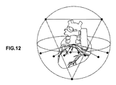
上述したシステムは、複数の心電図を連続して比較することを初めて可能にするものである。当該システムは、後部(posterior)ECG誘導を獲得するものであることが判っている。改造Mason−Likar誘導システムに依れば、16誘導ECGをマットレス、椅子、等に埋め込まれた前記センサマトリクス上に横たわる患者から獲得することができる。獲得される誘導は、図11および12に例示されているように、誘導I, II, aVr, aVl, aVf, V1, V1R, V2, V2R, V3, V3R, V4, V4R, V5, V5Rを含む。図11は、標準ECG誘導を得るための医学的に認識されたECG位置を図示し、図12は、標準ECG誘導の具体例を図示しており、これら各誘導は、人体上の二つの位置の間のベクトルとして図示されている。 The system described above makes it possible for the first time to compare several electrocardiograms in succession. The system has been found to acquire posterior ECG guidance. According to the modified Mason-Likar guidance system, a 16-lead ECG can be obtained from a patient lying on the sensor matrix embedded in a mattress, chair, etc. The leads obtained include leads I, II, aVr, aVl, aVf, V1, V1R, V2, V2R, V3, V3R, V4, V4R, V5, V5R, as illustrated in FIGS. . FIG. 11 illustrates medically recognized ECG positions for obtaining standard ECG leads, and FIG. 12 illustrates an example of standard ECG leads, each of which leads to two positions on the human body. Are shown as vectors between.
前記センサ10を含む前記パッドは、ECGデータが後部(posterior)誘導、たとえば、腹臥位、から得られるようにマットレスの下に気づかれない状態で配置することができる。前記システムは、ストレステスト中のECG獲得のために使用されるMason−Likarセンサ配置に基づくものとすることができる。標準12誘導ECG配置は、筋電位、動き、アーチファクト、等のために使用されず、10秒12誘導ECGプリントアウトに限定され、短時間又は長時間モニタリング用には実用的でない。
The pad containing the
後部配置された電極は、ECG獲得の一般に受け入れられた方法であって、事実、より一般的に使用されている前部誘導配置方法に対するある種の状況における補助として使用される。前部誘導配置は、現在において、その便利さから使用される唯一のタイプの誘導配置である。しかしながら、腹臥位ECG誘導は、ある種の状況においては、標準電極で行われるが、その固有の困難により、一般的ではない。 Rear-placed electrodes are a generally accepted method of ECG acquisition and, in fact, are used as an aid in certain situations to the more commonly used front-guided placement methods. The front guidance arrangement is currently the only type of guidance arrangement used for its convenience. However, prone ECG guidance is performed with standard electrodes in certain situations, but is not common due to its inherent difficulties.
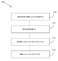
図14は、非接触式ECGセンサを使用する人体の心電図(ECG)信号を提供する方法のフローチャートである。図14に図示されているように、前記方法260は、非接触式ECGセンサのアレイから非接触式ECG信号を受け取ることによって工程262から始まる。工程264は、前記非接触式ECGセンサアレイの近傍に位置する人体部分を検出することを含む。工程266は、各グループから、最高の信号品質を有する非接触式ECGセンサを選択することを含む。工程268は、各選択された非接触式ECGセンサの非接触式ECG信号に基づいて標準ECG信号を作り出すことを含む。
FIG. 14 is a flowchart of a method for providing a human body electrocardiogram (ECG) signal using a non-contact ECG sensor. As shown in FIG. 14, the
以上、好適実施形態について記載し添付の図面に図示したが、本開示から逸脱することなく様々な改造を行うことが可能であることは当業者にとって自明であろう。そのような改造も、本開示の範囲の可能なバリエーションとして解釈される。 While the preferred embodiment has been described and illustrated in the accompanying drawings, it will be obvious to those skilled in the art that various modifications may be made without departing from the present disclosure. Such modifications are also to be construed as possible variations within the scope of the present disclosure.
Claims (20)
‐非接触式ECGセンサのアレイから前記人体の非接触式ECG信号を受け取るように構成された入力部、
‐以下の工程を含む選択処理を実行するように構成されたプロセッサ、
・前記人体の近傍に位置する非接触式ECGセンサから受け取ったデータを使用して前記人体の身体輪郭を得る工程、
・前記DPMに組み込まれた規則セットを使用して前記身体輪郭に位置する一つ又は複数の身体部分を検出する工程、
・各検出された身体部分と非接触式ECGセンサのグループとを関連付ける工程、
・各グループから当該グループの非接触式ECGセンサに関連付けられた前記身体部分に対する最高信号品質を有する非接触式ECGセンサを選択する工程、
前記プロセッサは、前記選択された非接触式ECGセンサから受け取った前記非接触式ECG信号に基づいて標準ECG信号を作り出すように構成されている、そして
‐前記標準ECG信号を前記遠隔/ローカル装置に送信する出力部。 A digital processing module (DPM) for providing an electrocardiogram (ECG) signal of a human body for storage and / or viewing on a remote / local device, the DPM comprising:
An input configured to receive a non-contact ECG signal of the human body from an array of non-contact ECG sensors;
A processor configured to perform a selection process comprising the following steps:
Obtaining a body contour of the human body using data received from a non-contact ECG sensor located in the vicinity of the human body;
Detecting one or more body parts located on the body contour using a rule set embedded in the DPM;
Associating each detected body part with a group of non-contact ECG sensors;
Selecting from each group a non-contact ECG sensor having the highest signal quality for the body part associated with the non-contact ECG sensor of the group;
The processor is configured to generate a standard ECG signal based on the non-contact ECG signal received from the selected non-contact ECG sensor; and-transmitting the standard ECG signal to the remote / local device. Output unit to send.
a.前記非接触式ECGセンサアレイ上の前記人体の位置を判定する工程、
b.前記非接触式ECGセンサをグループに分け、前記人体の前記身体輪郭と前記位置とを使用して各グループを一つの身体部分に関連付ける工程、
c.各グループから、前記最高信号品質を提供する非接触式ECGセンサを選択する工程。 2. The DPM of claim 1, wherein the processor is further configured to perform the following steps:
a. Determining the position of the human body on the non-contact ECG sensor array;
b. Dividing the non-contact ECG sensors into groups and associating each group with one body part using the body contour and the position of the human body;
c. Selecting, from each group, a non-contact ECG sensor that provides the highest signal quality.
‐非接触式ECGセンサのアレイを有するセンサパッド、
‐前記センサパッドに動作可能に接続されて前記非接触式ECGセンサから非接触式ECG信号を受け取り、以下の工程を含む選択処理を実行するように構成されたプロセッサ、
・前記人体の近傍に位置する非接触式ECGセンサから受け取ったデータを使用して前記人体の身体輪郭を得る工程、
・前記DPMに組み込まれた規則セットを使用して前記身体輪郭に位置する一つ又は複数の身体部分を検出する工程、
・各検出された身体部分に非接触式ECGセンサのグループを関連付ける工程、
・各グループから当該グループの非接触式ECGセンサに関連付けられた前記身体部分に対する最高信号品質を有する非接触式ECGセンサを選択する工程、
前記プロセッサは、前記選択された非接触式ECGセンサから受け取った前記非接触式ECG信号に基づいて標準ECG信号を作り出すように構成されている、そして
‐前記標準ECG信号を前記遠隔/ローカル装置に送信する出力部。 A system for providing an electrocardiogram (ECG) signal of a human body for storage and / or viewing on a remote / local device, the system comprising:
- Sensapa' de having a noncontact ECG sensor array,
A processor operatively connected to the sensor pad for receiving a non-contact ECG signal from the non-contact ECG sensor and performing a selection process comprising the following steps:
Obtaining a body contour of the human body using data received from a non-contact ECG sensor located in the vicinity of the human body;
Detecting one or more body parts located on the body contour using a rule set embedded in the DPM;
Associating a group of non-contact ECG sensors with each detected body part;
Selecting from each group a non-contact ECG sensor having the highest signal quality for the body part associated with the non-contact ECG sensor of the group;
The processor is configured to generate a standard ECG signal based on the non-contact ECG signal received from the selected non-contact ECG sensor; and-transmitting the standard ECG signal to the remote / local device. Output unit to send.
‐前記人体に容量結合されて、心臓の電気的活動を表す電荷を出力するように構成された容量電極、
‐前記容量電極によって作り出された前記電荷を検出し増幅するように構成されたエレクトロダイナミックセンサ、そして
‐前記エレクトロダイナミックセンサの入力部における浮遊干渉を低減するべく前記電極の近傍に物理的に提供される電極シールド。 10. The system of claim 9, wherein the non-contact ECG sensor comprises:
-A capacitive electrode capacitively coupled to the human body and configured to output a charge representative of electrical activity of the heart;
-An electrodynamic sensor configured to detect and amplify the charge created by the capacitive electrode; and-physically provided near the electrode to reduce stray interference at the input of the electrodynamic sensor. Electrode shield.
‐非接触式ECGセンサのアレイから非接触式ECG信号を受け取る工程、
‐前記非接触式ECGセンサから受け取ったデータを使用して前記人体の身体輪郭を得る工程、
‐前記身体輪郭に位置する身体部分を検出する工程、
‐各検出された身体部分に非接触式ECGセンサのグループを関連付ける工程、
‐各グループから当該グループの非接触式ECGセンサに関連付けられた前記身体部分に対する最高信号品質を有する非接触式ECGセンサを選択する工程、
‐前記選択された非接触式ECGセンサから受け取った前記非接触式ECG信号に基づいて標準ECG信号を作り出し出力する工程。 A method of providing an electrocardiogram (ECG) signal of a human body using a non-contact ECG sensor, the method including the following steps:
Receiving a non-contact ECG signal from an array of non-contact ECG sensors;
Obtaining a body contour of the human body using data received from the non-contact ECG sensor ;
Detecting a body part located at the body contour,
-Associating a group of non-contact ECG sensors with each detected body part;
Selecting from each group a non-contact ECG sensor having the highest signal quality for the body part associated with the non-contact ECG sensor of the group;
Generating and outputting a standard ECG signal based on the non-contact ECG signal received from the selected non-contact ECG sensor;
‐前記非接触式ECGセンサアレイ上の前記人体の位置を判定する工程、
‐前記非接触式ECGセンサをグループに分け、前記人体の前記身体輪郭と前記位置とを使用して各グループを一つの体部分に関連付ける工程、
‐各グループから、前記最高信号品質を有する前記非接触式ECG信号を提供する前記非接触式ECGセンサを選択する工程。 16. The method of claim 15, further comprising:
-Determining the position of the human body on the non-contact ECG sensor array;
Dividing the non-contact ECG sensors into groups and associating each group with one body part using the body contour and the position of the human body;
-Selecting from each group the non-contact ECG sensor providing the non-contact ECG signal with the highest signal quality;
‐各身体部分に関連付けられた前記選択された非接触式ECGセンサの現在の信号品質を連続的にモニタリングする工程、そして
‐前記非接触式ECGセンサアレイに対する前記人体の動きに追従して前記現在の信号品質が所与の閾値を超えて低下した時に、前記身体部分の少なくとも一つに対して別の非接触式ECGセンサを選択するために前記検出工程、前記関連付け工程及び前記選択工程を反復する工程。 16. The method of claim 15, further comprising:
-Continuously monitoring the current signal quality of the selected non-contact ECG sensor associated with each body part; and-tracking the current movement of the human body relative to the non-contact ECG sensor array. When the signal quality of the signal falls below a given threshold, the detecting, the associating, and the selecting are repeated to select another non-contact ECG sensor for at least one of the body parts. Process.
Applications Claiming Priority (5)
| Application Number | Priority Date | Filing Date | Title |
|---|---|---|---|
| US201462054189P | 2014-09-23 | 2014-09-23 | |
| US62/054,189 | 2014-09-23 | ||
| US201562206542P | 2015-08-18 | 2015-08-18 | |
| US62/206,542 | 2015-08-18 | ||
| PCT/CA2015/050938 WO2016044933A1 (en) | 2014-09-23 | 2015-09-23 | Contactless electric cardiogram system |
Publications (3)
| Publication Number | Publication Date |
|---|---|
| JP2017534346A JP2017534346A (en) | 2017-11-24 |
| JP2017534346A5 JP2017534346A5 (en) | 2018-11-01 |
| JP6646050B2 true JP6646050B2 (en) | 2020-02-14 |
Family
ID=55579995
Family Applications (1)
| Application Number | Title | Priority Date | Filing Date |
|---|---|---|---|
| JP2017516954A Expired - Fee Related JP6646050B2 (en) | 2014-09-23 | 2015-09-23 | Non-contact ECG system |
Country Status (15)
| Country | Link |
|---|---|
| US (4) | US10052042B2 (en) |
| EP (2) | EP3038523B1 (en) |
| JP (1) | JP6646050B2 (en) |
| KR (1) | KR101946174B1 (en) |
| CN (1) | CN107205678B (en) |
| AU (1) | AU2015321376B2 (en) |
| BR (1) | BR112016030185A2 (en) |
| CA (1) | CA2911304C (en) |
| ES (1) | ES2843690T3 (en) |
| HK (1) | HK1222307A1 (en) |
| IL (1) | IL251321B (en) |
| RU (1) | RU2677767C2 (en) |
| SG (1) | SG11201610065UA (en) |
| WO (1) | WO2016044933A1 (en) |
| ZA (1) | ZA201700649B (en) |
Families Citing this family (28)
| Publication number | Priority date | Publication date | Assignee | Title |
|---|---|---|---|---|
| WO2011020216A1 (en) * | 2009-08-18 | 2011-02-24 | Yang Changming | Product, method and system for monitoring physiological function and posture |
| RU2677767C2 (en) | 2014-09-23 | 2019-01-21 | Рр Сиквенсис Инк. | Non-contact registration system of electrocardiography |
| US9808202B2 (en) * | 2014-11-28 | 2017-11-07 | Shenzhen Novocare Medical Devices Co, INC | Mattress for measuring physiological parameters of heart |
| US20170231545A1 (en) * | 2016-02-14 | 2017-08-17 | Earlysense Ltd. | Apparatus and methods for monitoring a subject |
| EP3243430A1 (en) * | 2016-05-12 | 2017-11-15 | IMEC vzw | Device and method for controlling acquisition of a signal and a system for acquisition of a signal |
| WO2018020454A1 (en) * | 2016-07-29 | 2018-02-01 | Shingrani Rahul | Method and system for cardiac health monitoring |
| JP6778043B2 (en) * | 2016-08-04 | 2020-10-28 | フクダ電子株式会社 | Electrocardiogram recorder |
| CN106264517B (en) * | 2016-09-30 | 2019-05-14 | 浙江大学 | A kind of method and system selecting electrocardio measurement position |
| CN106691432B (en) * | 2016-10-19 | 2023-04-21 | 深圳市杰纳瑞医疗仪器股份有限公司 | Induction type electrocardio measuring method and device |
| US10307073B2 (en) | 2016-12-21 | 2019-06-04 | General Electric Company | ECG sensor with capacitive defibrillation protection |
| US10517488B2 (en) * | 2016-12-21 | 2019-12-31 | General Electric Company | Patient monitoring system and leadset having multiple capacitive patient connectors and a single galvanic patient connector |
| JP2018102710A (en) * | 2016-12-27 | 2018-07-05 | 株式会社豊田中央研究所 | Electrocardiographic measurement apparatus, method, and program |
| JP6800443B2 (en) * | 2017-01-31 | 2020-12-16 | 国立研究開発法人産業技術総合研究所 | Biological information detection sensor and biometric information measurement system |
| US10555679B2 (en) * | 2017-06-20 | 2020-02-11 | General Electric Company | Non-contact heart rate monitoring |
| MX2020001839A (en) * | 2017-09-01 | 2020-07-14 | Nestle Sa | Heart rate detection device and related systems and methods. |
| US10499827B2 (en) * | 2017-09-19 | 2019-12-10 | Honeywell International Inc. | System and method for interpretation of signal-to-noise ratios detected in an array of electrodes sensors in terms of physical and cognitive state |
| US20190184853A1 (en) * | 2017-12-19 | 2019-06-20 | GM Global Technology Operations LLC | Occupant sensing system for a vehicle |
| CN113164122A (en) * | 2018-11-12 | 2021-07-23 | 迈恩特公司 | Multi-sensor resistor woven ECG system |
| TWI715022B (en) * | 2019-04-29 | 2021-01-01 | 宏碁股份有限公司 | Smart care mattress and method for detecting the physiological state of user |
| CN111956229B (en) * | 2019-05-20 | 2023-05-23 | 宏碁股份有限公司 | Intelligent care mattress and method for detecting physiological state of user |
| WO2020255141A2 (en) * | 2019-06-20 | 2020-12-24 | Omnysense Ltd | A method for increasing cannabis yield via gene editing |
| US20210000348A1 (en) * | 2019-07-01 | 2021-01-07 | Wolfgang Richter | Apparatus for measuring vital signs |
| CN110426427A (en) * | 2019-09-07 | 2019-11-08 | 中国科学院宁波材料技术与工程研究所 | A kind of capacitive coupled sensors, preparation method and application |
| US20230165501A1 (en) * | 2020-04-03 | 2023-06-01 | Easyg Llc | System and methods for contactless monitoring of heart muscle activity and identifying medical conditions based on biopotential signals |
| US11806115B2 (en) * | 2020-05-21 | 2023-11-07 | GE Precision Healthcare LLC | Systems and methods for dynamic selection of sensors for obtaining physiological data from a patient |
| US20220039723A1 (en) * | 2020-08-07 | 2022-02-10 | Verily Life Sciences Llc | Multi-lead measurement of biopotentials with wearable device |
| CN113440347A (en) * | 2021-01-11 | 2021-09-28 | 宁波市第九医院 | Electric standing bed integrating non-contact cardiopulmonary function real-time monitoring and assessment |
| FR3131524A1 (en) * | 2021-12-31 | 2023-07-07 | Withings | Measuring station with electrocardiogram measurement |
Family Cites Families (102)
| Publication number | Priority date | Publication date | Assignee | Title |
|---|---|---|---|---|
| US5010772A (en) | 1986-04-11 | 1991-04-30 | Purdue Research Foundation | Pressure mapping system with capacitive measuring pad |
| US5353793A (en) | 1991-11-25 | 1994-10-11 | Oishi-Kogyo Company | Sensor apparatus |
| US6551252B2 (en) | 2000-04-17 | 2003-04-22 | Vivometrics, Inc. | Systems and methods for ambulatory monitoring of physiological signs |
| US5944669A (en) | 1997-11-20 | 1999-08-31 | Lifecor, Inc. | Apparatus and method for sensing cardiac function |
| US6553246B1 (en) | 1998-02-12 | 2003-04-22 | Unilead International, Inc. | Universal electrocardiogram sensor positioning device and method for four sizes including extra large |
| IL124900A0 (en) | 1998-06-14 | 1999-01-26 | Tapuz Med Tech Ltd | Apron for performing ecg tests and additional examinations |
| US6745062B1 (en) | 1998-10-05 | 2004-06-01 | Advanced Imaging Systems, Inc. | Emg electrode apparatus and positioning system |
| EP1204367B1 (en) | 1999-07-21 | 2007-04-18 | Daniel David | Physiological measuring system comprising a garment in the form of a sleeve or glove and sensing apparatus incorporated in the garment |
| US20050131465A1 (en) | 2000-02-04 | 2005-06-16 | Freeman Gary A. | Integrated resuscitation |
| US6584343B1 (en) | 2000-03-15 | 2003-06-24 | Resolution Medical, Inc. | Multi-electrode panel system for sensing electrical activity of the heart |
| US7485095B2 (en) | 2000-05-30 | 2009-02-03 | Vladimir Shusterman | Measurement and analysis of trends in physiological and/or health data |
| US6560473B2 (en) | 2001-03-02 | 2003-05-06 | Steven Dominguez | Disposable ECG chest electrode template with built-in defibrillation electrodes |
| US6847836B1 (en) | 2002-02-08 | 2005-01-25 | Lenny Sujdak | Emergency ECG electrode chest pad |
| US6932774B2 (en) | 2002-06-27 | 2005-08-23 | Denso Corporation | Respiratory monitoring system |
| US6961601B2 (en) | 2003-06-11 | 2005-11-01 | Quantum Applied Science & Research, Inc. | Sensor system for measuring biopotentials |
| US7559902B2 (en) | 2003-08-22 | 2009-07-14 | Foster-Miller, Inc. | Physiological monitoring garment |
| EP2319410A1 (en) | 2003-09-12 | 2011-05-11 | BodyMedia, Inc. | Apparatus for measuring heart related parameters |
| US20050137464A1 (en) * | 2003-12-23 | 2005-06-23 | Bomba Frank C. | Wireless sensor and sensor initialization device and method |
| US7254439B2 (en) | 2004-01-06 | 2007-08-07 | Monebo Technologies, Inc. | Method and system for contactless evaluation of fatigue of an operator |
| JP3809454B2 (en) | 2004-06-01 | 2006-08-16 | 独立行政法人科学技術振興機構 | Cardiac magnetic field diagnostic apparatus and operating method thereof |
| US7245956B2 (en) | 2004-07-15 | 2007-07-17 | Quantum Applied Science & Research, Inc. | Unobtrusive measurement system for bioelectric signals |
| KR100736721B1 (en) | 2004-08-31 | 2007-07-09 | 재단법인서울대학교산학협력재단 | Electric non-contact apparatus and method for taking electrocardiograms |
| US20090138059A1 (en) * | 2004-12-08 | 2009-05-28 | Koninklijke Philips Electronics N.V. | Heart Defibrillator With Contactless ECG Sensor For Diagnostics/Effectivity Feedback |
| JP5269584B2 (en) | 2005-03-25 | 2013-08-21 | ゾール メディカル コーポレイション | Integrated resuscitation |
| JP5253156B2 (en) * | 2005-06-07 | 2013-07-31 | コーニンクレッカ フィリップス エレクトロニクス エヌ ヴィ | Patient monitoring system and method |
| US7712373B2 (en) | 2006-03-03 | 2010-05-11 | Nagle H Troy | Sensor device for real-time monitoring or relative movement using capacitive fabric sensors |
| US7616980B2 (en) | 2006-05-08 | 2009-11-10 | Tyco Healthcare Group Lp | Radial electrode array |
| US9101264B2 (en) | 2006-06-15 | 2015-08-11 | Peerbridge Health, Inc. | Wireless electrode arrangement and method for patient monitoring via electrocardiography |
| US9131892B2 (en) | 2006-07-25 | 2015-09-15 | Gal Markel | Wearable items providing physiological, environmental and situational parameter monitoring |
| WO2008056309A2 (en) * | 2006-11-10 | 2008-05-15 | Koninklijke Philips Electronics, N.V. | Ecg electrode contact quality measurement system |
| US8238996B2 (en) | 2006-12-05 | 2012-08-07 | Tyco Healthcare Group Lp | Electrode array |
| US8140154B2 (en) | 2007-06-13 | 2012-03-20 | Zoll Medical Corporation | Wearable medical treatment device |
| US7974689B2 (en) | 2007-06-13 | 2011-07-05 | Zoll Medical Corporation | Wearable medical treatment device with motion/position detection |
| US7996056B2 (en) | 2007-06-15 | 2011-08-09 | The General Electric Company | Method and apparatus for acquiring physiological data |
| US8060175B2 (en) | 2007-06-15 | 2011-11-15 | General Electric Company | System and apparatus for collecting physiological signals from a plurality of electrodes |
| US20090088652A1 (en) | 2007-09-28 | 2009-04-02 | Kathleen Tremblay | Physiological sensor placement and signal transmission device |
| KR20100103537A (en) | 2007-11-28 | 2010-09-27 | 더 리전츠 오브 더 유니버시티 오브 캘리포니아 | Non-contact biopotential sensor |
| CN101896120B (en) * | 2007-12-12 | 2012-10-10 | 皇家飞利浦电子股份有限公司 | Sleep position detection |
| JP5535936B2 (en) | 2007-12-20 | 2014-07-02 | コーニンクレッカ フィリップス エヌ ヴェ | Capacitance detection and communication |
| KR20110008080A (en) | 2008-04-03 | 2011-01-25 | 카이 메디컬, 아이엔씨. | Non-contact physiologic motion sensors and methods for use |
| CN102046076A (en) * | 2008-04-03 | 2011-05-04 | Kai医药公司 | Non-contact physiologic motion sensors and methods for use |
| EP2826829B1 (en) * | 2008-08-06 | 2018-05-16 | Flexcon Company, Inc. | Biomedial sensor system and method of detecting a time varying biomedical signal |
| US8870780B2 (en) | 2008-10-15 | 2014-10-28 | The Board Of Trustees Of The Leland Stanford Junior University | Systems and methods for monitoring heart function |
| KR101040653B1 (en) | 2009-01-21 | 2011-06-10 | 서울대학교산학협력단 | Non-contact measuring devices of pulse wave and measuring devices of oxygen saturation and blood pressure in using same |
| JP2010194137A (en) | 2009-02-26 | 2010-09-09 | Ritsumeikan | Noncontact electrocardiographic sensor |
| KR101007818B1 (en) * | 2009-05-27 | 2011-01-14 | (주)경원유글로브 | Non-contact heartbeat sensor and heartbeat signal processing method using the same |
| US8374701B2 (en) | 2009-07-28 | 2013-02-12 | The Invention Science Fund I, Llc | Stimulating a nervous system component of a mammal in response to contactlessly acquired information |
| US9697336B2 (en) | 2009-07-28 | 2017-07-04 | Gearbox, Llc | Electronically initiating an administration of a neuromodulation treatment regimen chosen in response to contactlessly acquired information |
| US8346354B2 (en) | 2009-07-28 | 2013-01-01 | The Invention Science Fund I, Llc | Determining a neuromodulation treatment regimen in response to contactlessly acquired information |
| WO2011146482A1 (en) | 2010-05-18 | 2011-11-24 | Zoll Medical Corporation | Wearable ambulatory medical device with multiple sensing electrodes |
| US8611828B2 (en) | 2010-06-30 | 2013-12-17 | Wolfgang Richter | System and methods for self-powered, contactless, self-communicating sensor devices |
| WO2012007860A1 (en) * | 2010-07-16 | 2012-01-19 | Koninklijke Philips Electronics N.V. | Device including a multi-actuator haptic surface for providing haptic effects on said surface. |
| US8483811B2 (en) | 2010-08-02 | 2013-07-09 | Empire Technology Development Llc | Detection of biological information of a subject |
| DE102010034192A1 (en) | 2010-08-12 | 2012-02-16 | Capical Gmbh | ECG handset |
| WO2012088398A2 (en) | 2010-12-22 | 2012-06-28 | Cardioinsight Technologies, Inc. | Multi-layered sensor apparatus |
| CA2825405A1 (en) | 2011-01-27 | 2012-08-02 | The Board Of Trustees Of The Leland Stanford Junior University | Systems and methods for monitoring the circulatory system |
| KR101227413B1 (en) | 2011-03-08 | 2013-02-12 | (주)락싸 | Electrical contactless bio-electrical signal measurement apparatus and the method of the same |
| WO2012135028A1 (en) | 2011-03-25 | 2012-10-04 | Zoll Medical Corporation | Method of detecting signal clipping in a wearable ambulatory medical device |
| US8897860B2 (en) | 2011-03-25 | 2014-11-25 | Zoll Medical Corporation | Selection of optimal channel for rate determination |
| GB2489704B (en) * | 2011-04-04 | 2013-06-12 | Cardiocity Ltd | ECG mat |
| US9332919B2 (en) * | 2011-04-04 | 2016-05-10 | Cardiocity Limited | Heart monitoring apparatus |
| JP5370444B2 (en) | 2011-09-05 | 2013-12-18 | 株式会社デンソー | Electrocardiograph |
| WO2013075270A1 (en) * | 2011-11-25 | 2013-05-30 | Yang Chang-Ming | Object, method, and system for detecting heartbeat or whether or not electrodes are in proper contact |
| PT106102B (en) | 2012-01-19 | 2014-08-11 | Inst Superior Técnico | DEVICE AND METHOD FOR CONTINUOUS BIOMETRIC RECOGNITION BASED ON ELECTROCARDIOGRAPHIC SIGNS |
| US10182723B2 (en) | 2012-02-08 | 2019-01-22 | Easyg Llc | Electrode units for sensing physiological electrical activity |
| CN104717919B (en) | 2012-02-08 | 2018-10-12 | 易赛格有限责任公司 | ECG system with multi-mode electrically pole unit |
| JP6068820B2 (en) | 2012-04-19 | 2017-01-25 | テイ・エス テック株式会社 | Vehicle seat |
| CN102657524B (en) * | 2012-04-27 | 2013-11-20 | 东南大学 | Non-contact electrocardiogram sensor and application of non-contact electrocardiogram sensor |
| US20150241505A1 (en) * | 2012-08-01 | 2015-08-27 | Draeger Medical Systems, Inc. | System And Method For Measuring Contact Impedance Of An Electrode |
| KR101316497B1 (en) | 2012-08-03 | 2013-10-10 | 현대자동차주식회사 | System and method for observing heart rate of passenger |
| CN103845060A (en) * | 2012-11-30 | 2014-06-11 | 中国科学院理化技术研究所 | Portable fetal movement signal detection and analysis device |
| US9037221B2 (en) | 2013-01-16 | 2015-05-19 | University Of Rochester | Non-contact electrocardiogram system |
| US9088282B2 (en) * | 2013-01-25 | 2015-07-21 | Apple Inc. | Proximity sensors with optical and electrical sensing capabilities |
| KR101440444B1 (en) | 2013-01-31 | 2014-09-17 | 부경대학교 산학협력단 | Electrode structure for measuring bio-signal and apparatus for measuring electrocardiogram using the same |
| US20140249397A1 (en) | 2013-03-01 | 2014-09-04 | Thalmic Labs Inc. | Differential non-contact biopotential sensor |
| US9827431B2 (en) | 2013-04-02 | 2017-11-28 | West Affum Holdings Corp. | Wearable defibrillator with no long-term ECG monitoring |
| JP6298338B2 (en) | 2013-04-25 | 2018-03-20 | 日本光電工業株式会社 | Electrode pad |
| TWM462093U (en) | 2013-05-10 | 2013-09-21 | Wei-Chun Huang | Assisting device for twelve-lead electro-cardiographic inspection |
| US9642543B2 (en) | 2013-05-23 | 2017-05-09 | Arizona Board Of Regents | Systems and methods for model-based non-contact physiological data acquisition |
| DE102013216604A1 (en) | 2013-08-22 | 2015-02-26 | Ford Global Technologies, Llc | Sensor for contactless electrocardiographic measurement, sensor array and seat or couch |
| DE102013216682A1 (en) | 2013-08-22 | 2015-02-26 | Ford Global Technologies, Llc | Sensor for contactless electrocardiographic measurement, sensor array and seat or couch |
| KR101536139B1 (en) | 2013-09-05 | 2015-07-13 | 연세대학교 산학협력단 | Textile electrode kit, and the motion artifact-minimizing clothing installed with the kit |
| DE102013219026A1 (en) | 2013-09-23 | 2015-03-26 | Ford Global Technologies, Llc | Sensor for contactless electrocardiographic measurement, sensor array and seat or couch |
| WO2015045763A1 (en) * | 2013-09-25 | 2015-04-02 | 日産自動車株式会社 | Circuit for measuring bioelectric signal |
| US10213124B2 (en) | 2013-09-25 | 2019-02-26 | Zoll Medical Corporation | Electrocardiogram package |
| DE102013219513A1 (en) | 2013-09-27 | 2015-04-02 | Ford Global Technologies, Llc | Sensor for contactless electrocardiographic measurement, sensor array and seat or couch |
| US20160256104A1 (en) | 2013-10-18 | 2016-09-08 | Healthwatch Ltd. | Independent wearable health monitoring system, adapted to interface with a treatment device |
| US10064566B2 (en) * | 2013-11-25 | 2018-09-04 | Koninklijke Philips N.V. | Electrocardiography monitoring system and method |
| US9320446B2 (en) | 2013-12-09 | 2016-04-26 | Medtronic, Inc. | Bioelectric sensor device and methods |
| WO2015127193A1 (en) | 2014-02-20 | 2015-08-27 | Faurecia Automotive Seating, Llc. | Vehicle seat with integrated sensors |
| RU2677767C2 (en) | 2014-09-23 | 2019-01-21 | Рр Сиквенсис Инк. | Non-contact registration system of electrocardiography |
| US9662030B2 (en) | 2014-10-01 | 2017-05-30 | Verily Life Sciences Llc | Electrocardiography device for garments |
| TW201617026A (en) | 2014-11-11 | 2016-05-16 | 金寶電子工業股份有限公司 | Measuring system for respiration related signal and measuring method for the same |
| US9808202B2 (en) | 2014-11-28 | 2017-11-07 | Shenzhen Novocare Medical Devices Co, INC | Mattress for measuring physiological parameters of heart |
| JP2016123852A (en) | 2014-12-31 | 2016-07-11 | 現代自動車株式会社Hyundai Motor Company | Semi-contact type ecg measurement system and measuring method for the same |
| US10548495B2 (en) | 2015-04-01 | 2020-02-04 | Xtrava Inc. | Contactless or non-invasive physical properties measurement instrument using eddy current-reduced high Q resonant circuit probe |
| TWI565447B (en) | 2015-07-31 | 2017-01-11 | 高雄榮民總醫院 | Quick electrocardiogram device |
| KR101739542B1 (en) | 2015-10-07 | 2017-06-08 | 주식회사 헬스리안 | Wearable and wireless 12 channel electrocardiograph system |
| FR3043902B1 (en) | 2015-11-19 | 2018-02-23 | @Health | METHOD AND SYSTEM FOR ACQUIRING AND ANALYZING PHYSIOLOGICAL DATA |
| US10758184B2 (en) | 2016-06-30 | 2020-09-01 | Washington State University | Self-operable, non-invasive, non-contact bio-signal monitoring |
| KR101912870B1 (en) | 2016-09-29 | 2018-10-30 | 한국과학기술원 | A non-contact electrocardiography monitoring circuit and a method for non-contact electrocardiography monitoring and an appratus for electrocardiography monitoring |
| US9986929B1 (en) | 2017-03-01 | 2018-06-05 | CB Innovations, LLC | Emergency cardiac and electrocardiogram electrode placement system |
-
2015
- 2015-09-23 RU RU2017109707A patent/RU2677767C2/en active
- 2015-09-23 AU AU2015321376A patent/AU2015321376B2/en not_active Ceased
- 2015-09-23 CN CN201580050963.5A patent/CN107205678B/en active Active
- 2015-09-23 SG SG11201610065UA patent/SG11201610065UA/en unknown
- 2015-09-23 WO PCT/CA2015/050938 patent/WO2016044933A1/en active Application Filing
- 2015-09-23 BR BR112016030185A patent/BR112016030185A2/en not_active IP Right Cessation
- 2015-09-23 US US14/893,293 patent/US10052042B2/en not_active Expired - Fee Related
- 2015-09-23 ES ES15794450T patent/ES2843690T3/en active Active
- 2015-09-23 KR KR1020177005802A patent/KR101946174B1/en active IP Right Grant
- 2015-09-23 EP EP15794450.5A patent/EP3038523B1/en active Active
- 2015-09-23 EP EP20179908.7A patent/EP3785621A1/en active Pending
- 2015-09-23 CA CA2911304A patent/CA2911304C/en active Active
- 2015-09-23 JP JP2017516954A patent/JP6646050B2/en not_active Expired - Fee Related
-
2016
- 2016-09-05 HK HK16110545.1A patent/HK1222307A1/en unknown
-
2017
- 2017-01-26 ZA ZA2017/00649A patent/ZA201700649B/en unknown
- 2017-03-21 IL IL251321A patent/IL251321B/en active IP Right Grant
-
2018
- 2018-07-17 US US16/037,239 patent/US10939840B2/en active Active
- 2018-08-21 US US16/107,312 patent/US11064927B2/en active Active
-
2021
- 2021-02-01 US US17/164,694 patent/US11653867B2/en active Active
Also Published As
Similar Documents
| Publication | Publication Date | Title |
|---|---|---|
| JP6646050B2 (en) | Non-contact ECG system | |
| US9681825B2 (en) | Wireless electrode arrangement and method for patient monitoring via electrocardiography | |
| EP2073886B1 (en) | Wireless electrode arrangement and method for patient monitoring via electrocardiography | |
| US11793444B2 (en) | Electrocardiogram patch devices and methods | |
| EP1983895A1 (en) | A system and a method for wireless generation of standard ecg leads and an ecg sensing unit therefor | |
| KR101843083B1 (en) | Apparatus and method for measuring biological including multiple unit measurer | |
| CA3204059A1 (en) | Ambulatory electrocardiogram patch devices and methods | |
| TWI678186B (en) | Contactless electric cardiogram system | |
| KR20080084879A (en) | System for measuring physiological signal |
Legal Events
| Date | Code | Title | Description |
|---|---|---|---|
| A521 | Request for written amendment filed |
Free format text: JAPANESE INTERMEDIATE CODE: A523 Effective date: 20170525 |
|
| A529 | Written submission of copy of amendment under article 34 pct |
Free format text: JAPANESE INTERMEDIATE CODE: A529 Effective date: 20170323 |
|
| A521 | Request for written amendment filed |
Free format text: JAPANESE INTERMEDIATE CODE: A523 Effective date: 20180918 |
|
| A621 | Written request for application examination |
Free format text: JAPANESE INTERMEDIATE CODE: A621 Effective date: 20180918 |
|
| A131 | Notification of reasons for refusal |
Free format text: JAPANESE INTERMEDIATE CODE: A131 Effective date: 20190827 |
|
| A977 | Report on retrieval |
Free format text: JAPANESE INTERMEDIATE CODE: A971007 Effective date: 20190830 |
|
| A521 | Request for written amendment filed |
Free format text: JAPANESE INTERMEDIATE CODE: A523 Effective date: 20191127 |
|
| TRDD | Decision of grant or rejection written | ||
| A01 | Written decision to grant a patent or to grant a registration (utility model) |
Free format text: JAPANESE INTERMEDIATE CODE: A01 Effective date: 20191210 |
|
| A61 | First payment of annual fees (during grant procedure) |
Free format text: JAPANESE INTERMEDIATE CODE: A61 Effective date: 20200109 |
|
| R150 | Certificate of patent or registration of utility model |
Ref document number: 6646050 Country of ref document: JP Free format text: JAPANESE INTERMEDIATE CODE: R150 |
|
| LAPS | Cancellation because of no payment of annual fees |