JP6643433B2 - Supporting apparatus for creating an interpretation report and its control method - Google Patents
Supporting apparatus for creating an interpretation report and its control method Download PDFInfo
- Publication number
- JP6643433B2 JP6643433B2 JP2018164799A JP2018164799A JP6643433B2 JP 6643433 B2 JP6643433 B2 JP 6643433B2 JP 2018164799 A JP2018164799 A JP 2018164799A JP 2018164799 A JP2018164799 A JP 2018164799A JP 6643433 B2 JP6643433 B2 JP 6643433B2
- Authority
- JP
- Japan
- Prior art keywords
- area
- image data
- medical image
- region
- report
- Prior art date
- Legal status (The legal status is an assumption and is not a legal conclusion. Google has not performed a legal analysis and makes no representation as to the accuracy of the status listed.)
- Active
Links
Images


Description
本発明は、読影レポートの作成を支援する支援装置およびその制御方法に関する。 The present invention relates to a support device that supports creation of an interpretation report and a control method thereof.
医療の分野では、X線CT装置やMRI等の撮影装置により得られた医用画像データを医師が読影して診断を行う画像診断が行われている。画像診断では、主治医からの読影の依頼に応じて、医師が、画像から得られる所見(読影所見)や各種測定値を総合的に判断して画像に写る病変の症状を特定する。そして、医師は、その診断に至った経緯を読影所見や測定値を利用して、依頼元の主治医への読影レポートとしてまとめる。 2. Description of the Related Art In the medical field, image diagnosis is performed in which a doctor interprets medical image data obtained by an imaging device such as an X-ray CT device or an MRI to make a diagnosis. In image diagnosis, in response to a request for interpretation from the attending physician, a doctor comprehensively judges findings (interpretation findings) and various measurement values obtained from the image, and specifies symptoms of a lesion appearing in the image. Then, the doctor summarizes the circumstances leading to the diagnosis as an image interpretation report to the requesting attending physician using the image interpretation findings and measured values.
このような読影レポートの作成において、読影者の視線を検知することにより、読影レポート作成時の医用画像データの確認状況を把握する技術が知られている。特許文献1には、レポート作成時の入力情報と、その入力情報を入力している時に医用画像データ内で注目している部分(注目情報)を対応づけて格納する技術が記載されている。この技術によれば、医用画像データのどの部分に注目して読影レポートを作成したのかを把握することができる。特許文献2には、検査情報やコンピュータ支援診断機能を用いて観察すべき観察箇所を特定し、特定された観察箇所を視線情報に基づき確認したかを判定する技術が記載されている。この技術によれば、事前に定められた観察すべき箇所を確認したかを把握することができる。
In creating such an image interpretation report, a technique is known in which the gaze of the image interpreter is detected to grasp the confirmation status of medical image data at the time of creating the image interpretation report.
しかしながら、特許文献1では入力情報と注目情報を対応づけて格納するにとどまり、入力が行われていない注目領域(ユーザが注目したものの、レポートには記述されていない領域)や、入力情報と注目情報との整合性について考慮されていない。また、特許文献2の技術によれば、事前に定められた観察すべき観察箇所で入力が行われたかを判定することは可能であるが、事前に定められていない領域について入力が行われたかを判定することはできない。換言すると、観察するよう促されていない領域について医師が所見を持ったもののそれを入力し忘れた場合(以下、記述漏れと称する)には、注意を促すことはできなかった。また、入力内容と注目情報の整合性が考慮されていないため、たとえば、入力内容で指摘された領域が注目情報にないような不一致(以下、確認漏れと称する)が発生した場合に、注意を促すことはできなかった。
However, in
本発明は、上述したような課題に鑑みてなされたものであり、記述漏れおよび/または確認漏れの発生を低減して適切な読影レポートを作成するための支援を提供することを目的とする。 The present invention has been made in view of the above-described problems, and has as its object to provide support for reducing the occurrence of omission of description and / or omission of confirmation and creating an appropriate interpretation report.
上記の目的を達成するための本発明の一態様による支援装置は以下の構成を備える。すなわち、
読影レポートの作成を支援する支援装置であって、
読影対象の医用画像データを表示する表示手段と、
前記表示手段により表示された前記医用画像データにおいて読影時に注目された領域と判定された注目領域を取得する第1の取得手段と、
前記医用画像データに対応するレポート文に記述されている医学的な領域である記述領域を取得する第2の取得手段と、
前記注目領域と前記記述領域の整合性を判定する判定手段と、
前記判定手段による判定の結果に基づく情報を提示する提示手段と、を備える。
A support device according to one embodiment of the present invention for achieving the above object has the following configuration. That is,
A support device for supporting creation of an interpretation report,
Display means for displaying medical image data to be interpreted,
A first acquisition means for acquiring a target area that is determined as the target area during the interpretation in the medical image data displayed by the display means,
A second acquisition means for acquiring the description area is a medical area described in the report statement corresponding to the medical image data,
Determining means for determining consistency of the description area and the target area,
Presentation means for presenting information based on the result of the determination by the determination means.
本発明によれば、読影レポートの作成において、記述漏れまたは確認漏れの発生を低減することができる。 ADVANTAGE OF THE INVENTION According to this invention, generation | occurrence | production of a description omission or a confirmation omission can be reduced in preparation of an interpretation report.
以下、添付の図面を参照しながら、本発明の好適な実施形態について説明する。ただし、発明の範囲は図示例に限定されるものではない。 Hereinafter, preferred embodiments of the present invention will be described with reference to the accompanying drawings. However, the scope of the invention is not limited to the illustrated example.
[第1実施形態]
第1実施形態に係る読影レポート作成支援装置は、診断対象である症例に係る医用情報(医用画像データや電子カルテの情報など)や、ユーザからの入力情報(ユーザの視線情報やレポート文など)を取得し、当該症例に係る読影レポートの作成を支援する。ユーザとは、たとえば、医用画像データを読影する読影者である。以下では、医用画像データの一例として3次元の胸部X線CT画像データを扱う例を用いて説明する。もちろん本発明による読影の支援対象はこれに限定されるものではなく、たとえば、単純X線撮影による2次元画像や超音波断層像などの読影の支援にも適用可能である。以下に示す実施形態は、何れも読影レポート作成支援装置の処理の工程を説明するための一例に過ぎない。
[First Embodiment]
The interpretation report creation support device according to the first embodiment includes medical information (medical image data and electronic medical record information) relating to a case to be diagnosed and input information from a user (user's line-of-sight information and report text). To support the creation of an interpretation report for the case. The user is, for example, an interpreter who interprets medical image data. Hereinafter, a description will be given using an example in which three-dimensional chest X-ray CT image data is handled as an example of medical image data. Obviously, the subject of the interpretation support according to the present invention is not limited to this, and can be applied to, for example, support for interpretation of a two-dimensional image or an ultrasonic tomographic image by simple X-ray imaging. The embodiments described below are merely examples for describing the processing steps of the image interpretation report creation support device.
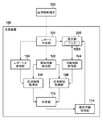
図1は、第1実施形態に係る読影レポート作成支援装置(以下、支援装置100)の機能構成例を示す。第1実施形態における支援装置100は、表示部200と症例情報端末300とに接続されている。表示部200は、モニタ1005(図2)を有し、システムやユーザの指示により様々な情報を表示する。モニタ1005に表示する具体的な内容に関しては後述する。
FIG. 1 shows an example of a functional configuration of an interpretation report creation support device (hereinafter, support device 100) according to the first embodiment. The
症例情報端末300は、診断対象である症例に関する医用情報、たとえば肺の異常陰影に係る医用情報(3次元医用画像データや電子カルテの情報など)を不図示のサーバから取得する。或いは、症例情報端末300は、外部記憶装置、例えばFDD、HDD、CDドライブ、DVDドライブ、MOドライブ、ZIPドライブ等を接続し、それらのドライブから医用情報を取得するようにしてもよい。また、症例情報端末300は、ユーザの要求に従い、肺の異常陰影に関する付随データ(腫瘍マーカー値などの臨床データや、対象患者の過去症例のレポートなど)を取得する。取得された医用情報や付随データはLAN等を介して支援装置100へと送信される。
The
支援装置100は、レポート作成部101と、領域情報取得部102と、視線情報取得部104と、レポート文取得部106と、注目領域取得部108と、記述領域取得部110と、判定部112と、提示情報作成部114とを備える。なお、支援装置100と症例情報端末300を別々の装置として示したが、これらは一体化されてもよい。
The
レポート作成部101は、レポート作成時の全体的な処理を行う。たとえば、レポート作成部101は、読影レポート作成画面(図5により後述)を表示部200のモニタ1005に表示する。読影レポート作成画面には、症例情報端末300から受信した読影対象の医用情報(医用画像データ)が表示され、ユーザは表示された医用画像データを読影して、後述のキーボード1007等を用いて読影レポートを入力する。こうして、ユーザは表示された医用情報(医用画像データなど)を観察することにより読影を行うことができる。
The
領域情報取得部102は、症例情報端末300から送信された医用画像データの座標位置と領域の対応付け情報(領域情報)を取得する。より具体的には、医用画像データの座標位置と医学的に分割された領域との対応付け情報を取得する。本実施形態では、医学的に分割された領域として解剖学的構造(たとえば、心臓、肝臓、右上葉など)が用いられる。取得した対応付け情報は注目領域取得部108、記述領域取得部110へと出力する。なお、このような領域情報の取得は、医用画像データに対し既知のセグメンテーション手法を適用し、セグメンテーション結果と画像の座標位置を対応づけることで実現できる。この様なセグメンテーション手法としては、たとえば、非特許文献1に記載の腹部の複数臓器同時抽出技術があげられる。なお、領域情報は、領域情報取得部102が読影対象の医用画像データを解析して取得してもよいし、症例情報端末300から送信される医用画像データに予め領域情報が含まれていてもよい。或いは、ユーザがマニュアルで解剖学的構造に対応する領域と名称を指定するようにしてもよい。
The area
視線情報取得部104は、ユーザが、医用画像データのどの位置を見ているかという視線情報を取得する。本実施形態では、視線情報取得部104は、モニタ1005上の視線位置を検出し、モニタ1005上における医用画像データの表示位置と検出された視線位置の座標に基づいて、対応する医用画像データ上の座標位置を取得し、これを視線情報とする。取得された視線情報は、注目領域取得部108へ出力される。なお、視線情報取得部104は、例えば複数の視点から同期撮影可能なビデオカメラやアイトラッカー等の視線追尾装置1045(図5)を用いてモニタ上の視線位置を検出することで実現できる。具体的には、ユーザの顔や目を複数の視点から撮影し、撮影により得られたステレオ画像に対して所定の画像認識処理を施すことにより、モニタ上で視線が向いた場所の座標位置を検出できる。視線追尾装置1045は、例えばモニタの端(モニタ直下など)などに配置される。
The line-of-sight
レポート文取得部106は、読影レポート作成画面を用いて入力された、ユーザが医用画像データを読影した結果であるレポート文(テキストデータ)を取得する。取得したレポート文は記述領域取得部110へと出力する。
The report
注目領域取得部108は、表示された医用画像データの医学的に分割された領域(たとえば、解剖学的構造に基づいて分割された領域)のうち、読影時にユーザが注目した領域である注目領域の集合を取得する。たとえば、注目領域取得部108は、領域情報取得部102が取得した領域情報と、視線情報取得部104が取得した視線情報を基に、表示されている医用画像データ上で注目した領域である注目領域を取得する。注目領域の具体的な内容については後述する。取得された注目領域は判定部112へと出力される。
The attention
記述領域取得部110は、医用画像データに対応するレポート文に記述されている医学的な領域(たとえば、解剖学的構造に基づく領域)である記述領域の集合を取得する。たとえば、記述領域取得部110は、領域情報取得部102が取得した領域情報と、レポート文取得部106が取得したレポート文を基に、記述領域を取得する。取得された記述領域は判定部112へと出力される。
The description
判定部112は、注目領域取得部108で取得した注目領域の集合と、記述領域取得部110で取得した記述領域の集合を基に、注目領域と記述領域の整合性を判定する。判定した結果は提示情報作成部114へと出力する。提示情報作成部114は、判定部112で判定した結果を基に提示情報を作成する。作成した提示情報は、例えば表示部200へ出力され、モニタ1005により提示される。
The
なお、図1に示した支援装置100の各部の少なくとも一部は独立した装置として実現してもよい。また、夫々が機能を実現するソフトウェアとして実現してもよい。本実施形態では各部はそれぞれ所定のソフトウェアをコンピュータが実行することにより実現されているものとする。
Note that at least a part of each unit of the
図2は、図1に示した各部の夫々の機能をソフトウェアを実行することで実現するためのコンピュータ装置の基本的なハードウェア構成を示す図である。すなわち、本実施形態の支援装置100は、コンピュータ装置により実現され得る。CPU1001は、主として各構成要素の動作を制御する。主メモリ1002は、CPU1001が実行する制御プログラムを格納したり、CPU1001によるプログラム実行時の作業領域を提供したりする。磁気ディスク1003は、オペレーティングシステム(OS)、周辺機器のデバイスドライブ、後述する処理等を行うためのプログラムを含む各種アプリケーションソフト等を格納する。
FIG. 2 is a diagram illustrating a basic hardware configuration of a computer device for realizing each function of each unit illustrated in FIG. 1 by executing software. That is, the
表示メモリ1004は、表示用データを一時記憶する。モニタ1005は、例えばCRTモニタや液晶モニタ等であり、表示メモリ1004からのデータに基づいて画像やテキストなどの表示を行う。マウス1006及びキーボード1007は、ユーザによるポインティング入力及び文字等の入力をそれぞれ行う。インターフェース1008は、支援装置100をネットワーク等に接続する。たとえば、インターフェース1008を介して症例情報端末300が支援装置100に接続される。上記各構成要素は、共通バス1009により互いに通信可能に接続されている。
The
次に、以上のような構成を備えた本実施形態の支援装置100が行う処理(読影時のレポート作成を支援する処理)について、図3のフローチャートを用いて説明する。本実施形態では、CPU1001が主メモリ1002に格納されている各部の機能を実現するプログラムを実行することにより実現される。なお、以下の説明では、モニタ1005の画面上の位置(画素)をMN座標系、医用画像データでの位置(ボクセル)をXYZ座標系で表す。また、以下の説明では、視線情報取得部104による視線情報の検出は、予め決められたサンプリングレート(例えば0.1秒)で取得するものとする。そして、ある時点での視線情報をOt(otx, oty,otz)(t = 1, 2, …)とする。
Next, a process performed by the
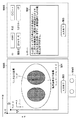
ステップS300において、レポート作成部101は、モニタ1005に、読影レポート作成画面を表示する。図5に示されるように、読影レポート作成画面は、読影対象の医用画像データを表示するための断層画像表示領域501、ユーザによるレポート(テキストデータ)の入力を受け付けるレポート文入力領域502、読影終了ボタン503を含む。断層画像表示領域501には、たとえば、医用画像データのaxial断層像が表示される。なお、図5に示される2つの画面は、1つのモニタの画面に同時に表示されてもよいし、1つのモニタの画面に切り替えて表示されてもよいし、2つのモニタを用いて別々に表示されてもよい。本実施形態では2つのモニタを用いて別々に表示されるものとし、後述の視線情報の取得は、医用画像データを表示したモニタに対して行われるものとする。
In step S300, the
次に、ステップS301において、領域情報取得部102は、症例情報端末300から送信された医用画像データ、すなわち読影対象の医用画像データの座標位置と被写体の解剖学的構造との対応付け情報(領域情報)を取得する。この領域情報は、例えば、解剖学的構造ごとに異なるラベルを割り当て、各ボクセルにラベルを紐づけた対応表として取得される。あるいは条件式の形で取得してもよい。夫々の例を図4(a)(b)に示す。図4(a)では、個々のボクセルに解剖学的構造を示すラベルが紐づけられた領域情報が示されている。また、図4(b)では、それぞれの解剖学的構造のラベルにボクセルの座標範囲を規定した領域情報が示されている。もちろん、これ以外の形式で領域情報を構成してもよい。以降では、図4(a)に示したような対応表の形式で領域情報を取得した場合を説明する。
Next, in step S301, the area
次に、ステップS302において、視線情報取得部104は、ユーザが、医用画像データのどの位置を見ているかという視線情報を取得する。また、レポート文取得部106は、ユーザが医用画像データを読影しその結果をまとめたレポート文を取得する。本実施形態では、レポート作成部101の制御下で、ユーザが図5に示すレポート文入力領域502にキーボード1007を用いてレポート文を入力することができる。
Next, in step S302, the line-of-sight
ここで、視線情報取得部104による視線情報の取得について説明する。図5はモニタ1005に読影レポート作成画面と読影対象の医用画像データを表示した例である。この例では、医用画像データから構成したaxial断層像が表示されている。axial断層像は体の上下(頭尾、体軸)に対して垂直な断層画像であり、本実施形態の座標系では、あるZ座標(体軸上のある位置)におけるXY平面の断層像として表される。モニタ1005の下には視線追尾装置1045が備え付けられており、ユーザがモニタ1005のどの位置(表示画素)を見ているかを、MN座標系の座標として検出する。
Here, the acquisition of the line of sight information by the line of sight
いま、簡単のために、モニタの表示画素とaxial断層像(XY平面)の画素の大きさが完全に一致する場合を考える。さらに、モニタの表示画素を示す座標(m, n)とaxial断層像の画素を示す座標(x, y)の対応関係が、x=m-a、y=n-bによって表されるものとする。換言すると、医用画像データの一ボクセルの値を、モニタの一画素で表示している場合を考える。この状態でモニタの一点(m, n)に着目すると、医用画像データでのx(= m-a)とy(= n-b)の値が定まる。さらに、表示されるaxial断層像に応じてzの位置が定まるため、モニタ上の座標(m, n)が定まると、医用画像データ上の座標(x, y, z)が一意に定まる。このことを利用して、視線追尾装置1045が検出したモニタ1005上の視線の座標から医用画像データ上で視線が向いた位置の座標(すなわち視線情報)を得ることができる。
Now, for the sake of simplicity, consider a case where the size of the display pixel of the monitor and the size of the pixel of the axial tomographic image (XY plane) completely match. Further, the correspondence between the coordinates (m, n) indicating the display pixel of the monitor and the coordinates (x, y) indicating the pixel of the axial tomographic image is represented by x = m-a, y = n-b. In other words, consider a case where the value of one voxel of medical image data is displayed on one pixel of a monitor. Focusing on one point (m, n) of the monitor in this state, the values of x (= m−a) and y (= n−b) in the medical image data are determined. Furthermore, since the position of z is determined according to the displayed axial tomographic image, when the coordinates (m, n) on the monitor are determined, the coordinates (x, y, z) on the medical image data are uniquely determined. By utilizing this, it is possible to obtain the coordinates of the position of the line of sight on the medical image data (that is, the line of sight information) from the coordinates of the line of sight on the
なお、モニタの表示画素とaxial断層像(XY平面)の画素の大きさが一致していない場合は、画素の大きさの比率を用いて医用画像データ上の位置の座標を計算することができる。また、視野を考慮し、モニタ1005の表示画素に対応するaxial断層像の画素の周辺の画素が示す医用画像データ上の座標位置も視線が向いた位置の座標として取得してもよい。すなわち、取得された一つの視線位置について複数の医用画像データ上の座標位置が取得されるようにしてもよい。
If the size of the display pixel of the monitor and the size of the pixel of the axial tomographic image (XY plane) do not match, the coordinates of the position on the medical image data can be calculated using the ratio of the size of the pixel. . Further, in consideration of the visual field, the coordinate position on the medical image data indicated by the pixels around the pixel of the axial tomographic image corresponding to the display pixel of the
ユーザは読影終了ボタン503を押下することにより、レポート文の入力終了を支援装置100に通知する。レポート文の入力終了が通知されると、処理はステップS302からステップS303へ進む。なお、ステップS303で読影終了ボタン503が押下されていないと判定された場合は、処理はステップS302に戻り、視線情報取得およびレポート文の入力の処理を継続する。
The user presses the image reading
ステップS304において、注目領域取得部108は、読影時に検出した視線位置に基づいて注目領域の集合を取得する。すなわち、注目領域取得部108は、ステップS300で取得した領域情報と、ステップS301において取得した視線情報を基に、医用画像データ上の医学的に分割された領域のうちのユーザによって注目された領域である注目領域を取得する。領域Aが注目領域か否かの判定方法としては、たとえば、
(1)読影時に断層画像表示領域501に表示された領域Aにおいて、視線位置が検出された画素(またはボクセル)の数NoAを取得し、
(2)表示された領域Aの全画素数(全ボクセル数)NaAを取得して、領域Aに含まれる画素の全数に対する視線位置が検出された画素の数の割合(NoA/NaA)が所定値を超える領域を注目領域とする、といった方法があげられる。なお、領域内に視線位置が存在した時間が所定時間を超える領域を注目領域とする、といった方法も考えられるが、時間のみで判定すると領域Aの全体を俯瞰していなくても注目した領域として判定されてしまう。したがって、視線位置が存在した時間を用いた判定と上述した割合(NoA/NaA)を用いた判定を組み合わせることが望ましい。たとえば、NoA/NaAが所定値を超え、且つ、領域Aに視線位置が存在した時間の合計が所定時間を超える場合に、領域Aを注目領域と判定するようにするのが好ましい。
In step S304, the attention
(1) In the area A displayed in the tomographic
(2) Obtain the total number of pixels (the total number of voxels) NaA in the displayed area A, and determine the ratio (NoA / NaA) of the number of pixels whose gaze position is detected to the total number of pixels included in the area A. A method of setting a region exceeding the value as a region of interest can be cited. Note that a method may be considered in which a region in which the line-of-sight position is present for a predetermined time period or longer is set as a region of interest. It will be judged. Therefore, it is desirable to combine the determination using the time when the line-of-sight position exists with the determination using the ratio (NoA / NaA) described above. For example, when NoA / NaA exceeds a predetermined value and the total time during which the line-of-sight position exists in the area A exceeds a predetermined time, it is preferable to determine the area A as the attention area.
本実施形態では、上記(1)、(2)の手順を用いる。より具体的には、一度でも観測されたボクセルを観測された領域とみなし、解剖学的構造が割り当てられたラベルごとに観測されたボクセル数を計数する。そしてラベルごとに観測されたボクセル数とそのラベルを持つボクセルの総数をもとに、そのラベル(すなわち解剖学的構造)が注視されたか判定する。例えば、あるラベルを持つボクセルの総数の一定割合より多いボクセルを観測した場合に、そのラベルに対応する解剖学的構造を注視したものと判定する。したがって、以下では、(1)(2)の手順で判定された注目領域を注視領域とも称する。 In the present embodiment, the above procedures (1) and (2) are used. More specifically, a voxel observed even once is regarded as an observed region, and the number of voxels observed for each label to which an anatomical structure is assigned is counted. Then, based on the number of voxels observed for each label and the total number of voxels having the label, it is determined whether the label (that is, the anatomical structure) has been watched. For example, when more than a certain percentage of the total number of voxels having a certain label is observed, it is determined that the anatomical structure corresponding to the label has been watched. Therefore, in the following, the attention area determined in the procedure of (1) and (2) is also referred to as the attention area.
図6を用いて説明する。図6において、601は領域情報と視線情報とあるZ位置(Z=6)でのaxial断層像を示したものである。602は、領域情報取得部102がaxial断層像601について取得した領域情報を示す。また、603は、視線情報取得部104が取得した視線情報である。
This will be described with reference to FIG. In FIG. 6,
axial断層像601の各ピクセル(x,y)に書かれた数字は、領域情報602が示す、各ボクセル(x, y, 6)に割り当てられたラベルを示したものである。例えば、ピクセル(3, 7)(すなわち、ボクセル(3, 7, 6))はラベルが「1」なので右上葉であることを示す。また、グレーで塗られたピクセルは、視線情報603により示されるピクセル(すなわち観測されたボクセル)を示す。視線情報603では、時刻Otにおける視線位置(x,y,z)(ボクセルの座標)が時系列に(Ot=O1、O2、O3…の順に)記録されている。この断層像の例では、観測されたボクセルは「0(体表外)」が2個、「1(右上葉)」が14個、「2(右中葉)」が9個、「3(右下葉)」が10個、「4(左上葉)」が6個、「5(左下葉)」が19個、「9(その他)」が23個となる。これを医用画像データ全体に適用することにより、医用画像データ全体での、ラベル毎の観測されたボクセル数を計数することができる。
The number written on each pixel (x, y) of the axial
本実施形態では、ラベルkの観測されたボクセル数をNok、ラベルkに属するボクセル総数をNakとし、Nok/Nak>0.8を満たす場合に、ラベルkの示す解剖学的構造を注視したものとする。なお、以下の説明では、「右上葉」と「右下葉」を注視領域として観測したものとする。 In the present embodiment, the observed number of voxels of label k is Nok, the total number of voxels belonging to label k is Nak, and when satisfying Nok / Nak> 0.8, it is assumed that the anatomical structure indicated by label k is watched. . In the following description, it is assumed that the “upper right lobe” and the “lower right lobe” are observed as the gaze areas.
ステップS305において、記述領域取得部110は、ステップS301で取得した領域情報と、ステップS303で取得したレポート文を基にレポート文に記述された領域である記述領域を取得する。本実施形態では、領域情報の各ラベルが示す解剖学的構造名をキーワードとし、レポート文に対してキーワードマッチングを用いて記述領域を取得するものとする。なお、類義語やオントロジーを用いてキーワードを拡張してマッチングを行ってもよい。例えば、図5に示したレポート文の例(レポート文入力領域502に示した例)では、「左上葉」と「右下葉」が記述領域として取得される。
In step S305, the description
ステップS306において、判定部112は、ステップS303で取得した注目領域(注視領域)と、ステップS305で取得した記述領域を基に、注目領域と記述領域の整合性を判定する。本実施形態では、注目領域(注視領域)に含まれていて記述領域に含まれていない情報があるかどうかを判定する。すなわち、注視したにも関わらずレポート文に記載していない記述漏れがあるかどうかを判定する。上記の例では、注視領域である「右上葉」が記述領域に含まれていないため、記述漏れがあると判定する。
In step S306, the
ステップS307において、提示情報作成部114は、ステップS306で判定した結果を基に提示情報を作成する。本実施形態では、提示情報としてメッセージボックスを作成するものとする。前述した例では、「右上葉」が記述領域に含まれていないため、その旨を通知するメッセージボックスを作成する。そして、ステップS308において、提示情報作成部114は、作成したメッセージボックスをモニタ1005に表示する。
In step S307, the presentation
図7は、本実施形態においてモニタ1005に表示される提示情報の一例を示す。提示情報はメッセージボックス704の形式で表示される。ここで、メッセージボックス704の「はい」ボタンを押下すると、レポート文の修正(再入力)が可能である。すなわち、ステップS309において修正を行う支持が入力されたと判定され、処理がステップS302へ戻り、レポート作成部101によるレポート文の作成(編集)が可能となる。一方「いいえ」ボタンを押下すると、処理はステップS310へ進み、レポート作成部101はレポート文を磁気ディスク1003等に保存してレポート作成支援処理を終了する。
FIG. 7 shows an example of presentation information displayed on the
なお、ステップS306において整合性の判定に合格した場合(記述漏れが無いと判定された場合)は、たとえば、その旨を表示するメッセージボックスを生成して表示し、レポート文の作成を継続するか否かを問い合わせるようにしてもよい。あるいは、記述漏れがなかったと判定された場合には、上述した「いいえ」ボタンを押下した場合と同様に、レポート文を保存して終了するようにしてもよい。 If the consistency is passed in step S306 (if it is determined that there is no omission in description), for example, a message box for displaying the fact is generated and displayed, and whether to continue to create a report sentence. It may be inquired about whether or not it is not. Alternatively, when it is determined that there is no omission of the description, the report sentence may be saved and the process may be ended similarly to the case where the above-mentioned “No” button is pressed.
以上のように、本実施形態によれば、読影時に注視していたにも関わらずレポート文に記述されていない領域に関し、医師に記述漏れの注意喚起を行うことができる。そのため、医師は記述漏れのないレポート文を作成することができる。特に、医用画像データを一通り閲覧した後、一括してレポート文を記載する読影スタイルにおいて有効に作用することが期待できる。これにより、医師は適切な読影レポートを作成することができる。 As described above, according to the present embodiment, it is possible to alert the doctor to omission of description in an area that is not noted in the report sentence despite being watched at the time of interpretation. Therefore, the doctor can create a report sentence with no omission. In particular, it is expected that after reading the medical image data all at once, it will work effectively in the interpretation style in which report texts are collectively described. Thereby, the doctor can create an appropriate interpretation report.
[第2実施形態]
第1実施形態では、注目領域の集合と記述領域の集合の整合性の判定により「記述漏れ」を検出し、注意喚起を行う構成を説明した。第2実施形態に関わる読影レポート作成支援装置は、医師がレポート文に記述していたにも関わらず、読影時に注視していない領域に関し、医師に注意喚起を行う。すなわち、第2実施形態では、確認漏れに対する注意喚起を行う構成を説明する。
[Second embodiment]
In the first embodiment, the description has been given of a configuration in which “missing description” is detected by determining the consistency between the set of attention areas and the set of description areas, and a warning is issued. The interpretation report creation support device according to the second embodiment alerts the doctor about an area that is not watched at the time of interpretation even though the doctor has described the report text. That is, in the second embodiment, a configuration in which a warning is given for omission of confirmation is described.
第2施形態に係る読影レポート作成のための支援装置100の構成は第1実施形態(図1)と同様である。また、ソフトウェアの実行によって支援装置100の読影レポート作成支援処理を実現するコンピュータの基本構成も、第1実施形態(図2)と同様である。また、支援装置100が行う全体の処理を説明するフローチャートは図3と同様である。ただし、処理の一部が第1実施形態とは異なっている。以下、図3のフローチャートを参照して、第2実施形態に係る支援装置100が行う全体の処理について説明する。
The configuration of the
ステップS300からステップS305、ステップS307からステップS310の処理は第1実施形態における処理と同様である。ステップS306において、判定部112は、ステップS304で取得した注目領域の集合と、ステップS305で取得した記述領域の集合を基に、注目領域と記述領域の整合性を判定する。
The processing from step S300 to step S305 and the processing from step S307 to step S310 are the same as the processing in the first embodiment. In step S306, the
本実施形態では、記述領域に含まれていて注目領域に含まれていない情報があるかどうかを判定する。なお、第1実施例と同様に、注視領域を用いるものとする。すなわち、医師が記述したにも関わらず読影時に注視していなかった確認漏れがあるかどうかを判定する。例えば、第1実施形態で説明した例のように、注視領域が「右上葉」「右下葉」で、記述領域が「左上葉」と「右下葉」である場合を考える。この場合は、記述領域である「左上葉」が注視領域に含まれていないため、確認漏れがあると判定する。 In the present embodiment, it is determined whether there is information included in the description area and not included in the attention area. Note that, similarly to the first embodiment, the gaze area is used. That is, it is determined whether there is any omission in confirmation that the doctor did not pay attention during interpretation even though the description was made. For example, as in the example described in the first embodiment, consider the case where the gaze area is “upper right lobe” and “lower right lobe” and the description areas are “upper left lobe” and “lower right lobe”. In this case, since the description area “upper left lobe” is not included in the gaze area, it is determined that there is a confirmation omission.
なお、本実施形態では、ステップS308で提示される提示情報としてシェーマ画像を含むメッセージボックスを作成するものとする。具体的には、確認漏れの領域に対応する解剖学的構造を強調した画像を含むメッセージボックスを作成するものとする。前述した例では、「左上葉」が注視領域に含まれていないため、「左上葉」を強調したシェーマ画像を含むメッセージボックスを作成する。そして、作成したメッセージボックスをモニタ1005へと表示する。
In the present embodiment, a message box including a schema image is created as presentation information presented in step S308. Specifically, it is assumed that a message box including an image in which the anatomical structure corresponding to the unchecked region is emphasized is created. In the above-described example, since “upper left” is not included in the gaze area, a message box including a schema image in which “upper left” is emphasized is created. Then, the created message box is displayed on the
図8は、本実施形態においてモニタ1005に表示される提示情報の一例を示す。提示情報はメッセージボックス805の形式で表示される。ここで、メッセージボックス805の「はい」ボタンを押下すると、再度読影をすることが可能である(すなわち、ステップS301の処理へと戻る)。一方「いいえ」を押下すると、支援装置100はレポート文を保存して終了する。
FIG. 8 shows an example of presentation information displayed on the
なお、ステップS306において確認漏れがなかったと判定された場合には、先ほど説明した「いいえ」を押下した場合と同様に、レポート文を保存して終了する。なお、ステップS306において確認漏れがなかったと判定された場合に、その旨を表示するメッセージボックスを生成して表示し、レポート文の作成を継続するか否かを問い合わせるようにしてもよい。 If it is determined in step S306 that there is no omission in confirmation, the report sentence is saved and the process ends, similarly to the case where "NO" is pressed as described above. If it is determined in step S306 that there is no omission, a message box may be generated and displayed to indicate that, and an inquiry may be made as to whether or not to continue creating a report sentence.
以上のように、第2実施形態によれば、医師がレポート文に記述したにも関わらず、読影時に注視してなかった領域に関し、医師に確認漏れの注意喚起を行うことができる。そのため、医師が注視していない領域に関して記述することを防ぐことができる。 As described above, according to the second embodiment, it is possible to alert the doctor to omission of confirmation in an area that is not watched at the time of interpretation even though the doctor describes the report sentence. Therefore, it is possible to prevent a doctor from describing a region that is not watched.
また、別の効果として、過去の読影レポートが存在するフォローアップ症例の読影において、過去の読影レポートを流用してレポート文を作成した場合に有効に作用することが期待できる。すなわち、過去のレポートを流用して現在の状態にそぐわない記述をそのまま残してしまった場合に、確認漏れの警告がでることで、医師が現在の状態に対するレポートにおいて不要な記述の存在に気づくことが期待できる。以上のような構成により、医師は適切な読影レポートを作成することができる。 Further, as another effect, it can be expected that in the interpretation of a follow-up case in which a past interpretation report exists, the effect is effectively exerted when a report sentence is created by diverting the past interpretation report. In other words, if a previous report is diverted and a description that does not fit the current state is left as it is, a warning of omission of confirmation will be issued, so that the doctor will notice the existence of unnecessary description in the report for the current state. Can be expected. With the above configuration, the doctor can create an appropriate interpretation report.
(変形例1)
第1および第2実施形態では、ステップS304において、注目領域として、断層画像表示領域501に表示されたaxial断層像が示す領域の中で視線情報が得られた注視領域を用いた例を説明した。しかしながら、領域が注目されたか否かを判定する方法として、必ずしも視線位置が検出されたか否かを用いる必要はない。変形例1では、axial断層像のうちの表示された領域を視線位置が検出された領域と同等に扱って注目領域を決定する。すなわち、第1実施形態で説明した、領域Aのうちの視線位置が検出された画素(ボクセル)の数NoAとして、領域Aのうちのモニタ1005により表示された部分の画素数が用いられる。
(Modification 1)
In the first and second embodiments, an example has been described in which, in step S <b> 304, a gaze area in which line-of-sight information is obtained in an area indicated by an axial tomographic image displayed in the tomographic
図9はモニタで表示した領域を注目領域とする例を説明する図である。図9(a)は、一般的な医用画像ビューアの機能でaxial断層像906を平行移動した状態で読影している場合を示した例である。この場合、断層画像表示領域501内で表示されている部分のみを注目領域とする。この例ではaxial断層像906のうち、ハッチングされた部分が医用画像データのうちの読影時に表示された部分となる。したがって、医用画像データ(axial断層像906)のハッチングされた部分に少なくとも一部が属している医学的な領域のそれぞれについて、読影時に表示された画素数とその領域の総画素数との比からその領域が注目領域か否かが判定される。図9(b)は一般的な医用画像ビューアの機能でaxial断層像906を拡大表示した状態で読影している場合を示した例である。この例ではaxial断層像906のうち、ハッチングされた部分が読影時に表示される領域となる。上述したように、医用画像データ(axial断層像906)の医学的に分割された領域のうち少なくとも一部がハッチングされた部分に属している領域が、注目領域か否かを判定する対象となる。なお、axial断層像906を縮小表示した状態(すなわち、断層画像表示領域501にaxial断層像906の全体が収まっている場合)は、当然、axial断層像906が示す領域全てが注目領域となる。
FIG. 9 is a diagram illustrating an example in which a region displayed on a monitor is set as a region of interest. FIG. 9A shows an example of a case in which the interpretation of the axial
(変形例2)
第1および第2実施形態では、ステップS304において、具体的な解剖学的構造として注目領域を取得し、ステップS305において取得した解剖学的構造を示す記述領域を基に、ステップS306において整合性を判定していた。しかし、整合性の判定はこの方法に限定されない。
(Modification 2)
In the first and second embodiments, in step S304, a region of interest is acquired as a specific anatomical structure. Based on the description region indicating the anatomical structure acquired in step S305, consistency is determined in step S306. Had been determined. However, the determination of consistency is not limited to this method.
例えば、ステップS304では、注目領域取得部108が観測されたボクセル(視線が存在したボクセル)の全てを注目領域として取得し、ステップS301で取得した領域情報を用いて解剖学的構造ごとのボクセル群へと変換する。そして、ステップS306において、判定部112が、記述領域が示す解剖学的構造ごとのボクセル群に、注目領域として取得されたボクセルがどれくらい含まれているかにより整合性を判定するようにしてもよい。
For example, in step S304, the attention
(変形例3)
第1および第2実施形態では、第1実施形態の方法により記述漏れの判定を、第2実施形態の方法により確認漏れの判定を別々に行っていた。しかし、必ずしも別々に行う必要はなく、記述漏れの判定と確認漏れの判定を同時に行ってもよい。すなわち、整合性の判定において、第1実施形態で説明した記述漏れ、第2実施形態で説明した確認漏れの両方を判定するようにしてもよい。また、その場合に、注目領域の集合の取得の仕方を、記述漏れの検出と確認漏れの検出とで異ならせてもよい。たとえば、記述漏れを検出するための注目領域の集合は視線が一度でも存在した領域の集合とし、確認漏れを検出するための注目領域の集合は注視領域の集合とするようにしてもよい。
(Modification 3)
In the first and second embodiments, the omission of description is determined separately by the method of the first embodiment, and the omission of confirmation is determined separately by the method of the second embodiment. However, it is not always necessary to perform the determination separately, and the determination of omission of description and the determination of omission of confirmation may be performed simultaneously. That is, in the determination of consistency, both the omission of description described in the first embodiment and the omission of confirmation described in the second embodiment may be determined. In such a case, the method of acquiring the set of attention areas may be different between the detection of the omission of description and the detection of the omission of confirmation. For example, a set of attention areas for detecting omission of description may be a set of areas where a line of sight has existed even once, and a set of attention areas for detecting omission of confirmation may be a set of attention areas.
また、第1および第2実施形態では、注目領域の同定に読影レポート作成画面に表示されたこと、視線位置が存在したことを用いたが、これらに限られるものではない。たとえば、モニタ1005にタッチパネル等のタッチ入力部を設け、読影中にユーザが注目した位置をタッチ入力するようにするようにしてもよい。この場合、注目領域取得部108は、このタッチ入力位置に基づいて注目領域を取得する。
Further, in the first and second embodiments, the fact that the region of interest is displayed on the image interpretation report creation screen and that the line of sight is present is used, but the present invention is not limited to these. For example, a touch input unit such as a touch panel may be provided on the
また、本発明は、以下の処理を実行することによっても実現される。即ち、上述した実施形態の機能を実現するソフトウェア(プログラム)を、ネットワーク又は各種記憶媒体を介してシステム或いは装置に供給し、そのシステム或いは装置のコンピュータ(またはCPUやMPU等)がプログラムを読み出して実行する処理である。 The present invention is also realized by executing the following processing. That is, software (program) that realizes the functions of the above-described embodiments is supplied to a system or apparatus via a network or various storage media, and a computer (or CPU, MPU, or the like) of the system or apparatus reads the program and reads the program. This is the process to be performed.
100:読影レポート作成支援装置、102:領域情報取得部、104:視線情報取得部、106:レポート文取得部、108:注目領域取得部、110:記述領域取得部、112:判定部、114:提示部、200:表示部 100: interpretation report creation support device, 102: area information acquisition unit, 104: gaze information acquisition unit, 106: report sentence acquisition unit, 108: attention area acquisition unit, 110: description area acquisition unit, 112: determination unit, 114: Presentation unit, 200: display unit
Claims (12)
読影対象の医用画像データを表示する表示手段と、
前記表示手段により表示された前記医用画像データにおいて読影時に注目された領域と判定された注目領域を取得する第1の取得手段と、
前記医用画像データに対応するレポート文に記述されている医学的な領域である記述領域を取得する第2の取得手段と、
前記注目領域と前記記述領域の整合性を判定する判定手段と、
前記判定手段による判定の結果に基づく情報を提示する提示手段と、を備えることを特徴とする支援装置。 A support device for supporting creation of an interpretation report,
Display means for displaying medical image data to be interpreted,
A first acquisition means for acquiring a target area that is determined as the target area during the interpretation in the medical image data displayed by the display means,
A second acquisition means for acquiring the description area is a medical area described in the report statement corresponding to the medical image data,
Determining means for determining consistency of the description area and the target area,
And a presentation unit for presenting information based on a result of the determination by the determination unit.
前記第1の取得手段は、読影時に検出した視線位置に基づいて前記注目領域を取得することを特徴とする請求項1に記載の支援装置。 Further comprising detection means for detecting the line of sight of the radiogram interpreter,
It said first acquisition means support device according to claim 1, characterized in that obtaining the target area based on the detected line-of-sight position during interpretation.
前記第1の取得手段は、前記医用画像データを表示する前記表示手段へのタッチ入力位置に基づいて前記注目領域を取得することを特徴とする請求項1に記載の支援装置。 The display means has a touch input means,
It said first acquisition means support device according to claim 1, characterized in that obtaining the target area based on the touch input position to the display means for displaying the medical image data.
前記第2の取得手段は、前記レポート文に記述されている解剖学的構造名を前記記述領域として取得することを特徴とする請求項1乃至6のいずれか1項に記載の支援装置。 The medically divided region of the medical image data is a region that is divided based on an anatomical structure,
7. The support apparatus according to claim 1, wherein the second acquisition unit acquires an anatomical structure name described in the report sentence as the description area. 8.
読影対象の医用画像データを表示手段に表示する表示工程と、
前記表示手段に表示された前記医用画像データの医学的に分割された領域のうち、読影時に注目した領域と判定された注目領域を取得する第1の取得工程と、
前記医用画像データに対応するレポート文に記述されている医学的な領域である記述領域を取得する第2の取得工程と、
前記注目領域と前記記述領域の整合性を判定する判定工程と、
前記判定工程による判定の結果に基づく情報を提示する提示工程と、を有することを特徴とする支援装置の制御方法。 A control method of a support device that supports creation of an image interpretation report,
A display step of displaying medical image data to be interpreted on display means,
Among medically divided region of the medical image data displayed on said display means, a first acquisition step for acquiring target area that is determined to be focused on during image interpretation area,
A second acquisition step of acquiring a description area is a medical area described in the report statement corresponding to the medical image data,
A determination step of determining consistency of the description area and the target area,
A presentation step of presenting information based on a result of the determination in the determination step.
Priority Applications (1)
| Application Number | Priority Date | Filing Date | Title |
|---|---|---|---|
| JP2018164799A JP6643433B2 (en) | 2018-09-03 | 2018-09-03 | Supporting apparatus for creating an interpretation report and its control method |
Applications Claiming Priority (1)
| Application Number | Priority Date | Filing Date | Title |
|---|---|---|---|
| JP2018164799A JP6643433B2 (en) | 2018-09-03 | 2018-09-03 | Supporting apparatus for creating an interpretation report and its control method |
Related Parent Applications (1)
| Application Number | Title | Priority Date | Filing Date |
|---|---|---|---|
| JP2014181591A Division JP6397277B2 (en) | 2014-09-05 | 2014-09-05 | Support device for interpretation report creation and control method thereof |
Publications (3)
| Publication Number | Publication Date |
|---|---|
| JP2019008816A JP2019008816A (en) | 2019-01-17 |
| JP2019008816A5 JP2019008816A5 (en) | 2019-03-22 |
| JP6643433B2 true JP6643433B2 (en) | 2020-02-12 |
Family
ID=65028916
Family Applications (1)
| Application Number | Title | Priority Date | Filing Date |
|---|---|---|---|
| JP2018164799A Active JP6643433B2 (en) | 2018-09-03 | 2018-09-03 | Supporting apparatus for creating an interpretation report and its control method |
Country Status (1)
| Country | Link |
|---|---|
| JP (1) | JP6643433B2 (en) |
Families Citing this family (1)
| Publication number | Priority date | Publication date | Assignee | Title |
|---|---|---|---|---|
| CN111354444A (en) * | 2020-02-28 | 2020-06-30 | 上海商汤智能科技有限公司 | Pathological section image display method and device, electronic equipment and storage medium |
Family Cites Families (5)
| Publication number | Priority date | Publication date | Assignee | Title |
|---|---|---|---|---|
| JP2004267273A (en) * | 2003-03-05 | 2004-09-30 | Sangaku Renkei Kiko Kyushu:Kk | Medical system |
| JP4450695B2 (en) * | 2004-08-19 | 2010-04-14 | 富士通株式会社 | Interpretation report analysis program |
| JP2007319327A (en) * | 2006-05-31 | 2007-12-13 | Hitachi Medical Corp | Diagnostic reading support system |
| JP5067793B2 (en) * | 2007-08-15 | 2012-11-07 | 富士フイルム株式会社 | Medical information processing system, medical information processing method, and program |
| JP6071627B2 (en) * | 2012-03-26 | 2017-02-01 | 東芝メディカルシステムズ株式会社 | Medical information management device |
-
2018
- 2018-09-03 JP JP2018164799A patent/JP6643433B2/en active Active
Also Published As
| Publication number | Publication date |
|---|---|
| JP2019008816A (en) | 2019-01-17 |
Similar Documents
| Publication | Publication Date | Title |
|---|---|---|
| US7518619B2 (en) | Method and apparatus for integrating three-dimensional and two-dimensional monitors with medical diagnostic imaging workstations | |
| US20070270689A1 (en) | Respiratory gated image fusion of computed tomography 3D images and live fluoroscopy images | |
| US8494242B2 (en) | Medical image management apparatus and method, and recording medium | |
| US20120299818A1 (en) | Medical information display apparatus, operation method of the same and medical information display program | |
| US8306292B2 (en) | Image display device and image display program storage medium | |
| JP6397277B2 (en) | Support device for interpretation report creation and control method thereof | |
| JP4744926B2 (en) | Medical image display device and medical image display method | |
| EP2878266A1 (en) | Medical imaging system and program | |
| US20160314589A1 (en) | Medical image displaying device and a non-transitory computer-readable recording medium | |
| US20020158875A1 (en) | Method, apparatus, and program for displaying images | |
| JP2001218110A (en) | Inter-image arithmetic method and device, and image display method and device | |
| US9597049B2 (en) | Image display control device, operating method for same, and image display control program | |
| JP6643433B2 (en) | Supporting apparatus for creating an interpretation report and its control method | |
| JP5100041B2 (en) | Image processing apparatus and image processing program | |
| JP2006187412A (en) | Medical image-based diagnosis supporting apparatus | |
| JP2019046057A (en) | Image processing device, image processing method and program | |
| US20190304107A1 (en) | Additional information display device, additional information display method, and additional information display program | |
| JP2017207793A (en) | Image display device and image display system | |
| US20070286525A1 (en) | Generation of imaging filters based on image analysis | |
| US11437136B2 (en) | Image processing apparatus, image processing method, and storage medium | |
| JP2001087228A (en) | Image reading support device | |
| US20080117229A1 (en) | Linked Data Series Alignment System and Method | |
| JP5546780B2 (en) | Medical image interpretation request device and medical image interpretation request system | |
| JP2008289923A (en) | Image displaying method and apparatus, and program | |
| US20090128304A1 (en) | Method and apparatus for tactile interface for reviewing radiological images |
Legal Events
| Date | Code | Title | Description |
|---|---|---|---|
| A621 | Written request for application examination |
Free format text: JAPANESE INTERMEDIATE CODE: A621 Effective date: 20181003 |
|
| A521 | Written amendment |
Free format text: JAPANESE INTERMEDIATE CODE: A523 Effective date: 20190204 |
|
| TRDD | Decision of grant or rejection written | ||
| A01 | Written decision to grant a patent or to grant a registration (utility model) |
Free format text: JAPANESE INTERMEDIATE CODE: A01 Effective date: 20191202 |
|
| A61 | First payment of annual fees (during grant procedure) |
Free format text: JAPANESE INTERMEDIATE CODE: A61 Effective date: 20200106 |
|
| R151 | Written notification of patent or utility model registration |
Ref document number: 6643433 Country of ref document: JP Free format text: JAPANESE INTERMEDIATE CODE: R151 |