JP6641613B2 - Toner container, process cartridge, and image forming apparatus - Google Patents
Toner container, process cartridge, and image forming apparatus Download PDFInfo
- Publication number
- JP6641613B2 JP6641613B2 JP2015118769A JP2015118769A JP6641613B2 JP 6641613 B2 JP6641613 B2 JP 6641613B2 JP 2015118769 A JP2015118769 A JP 2015118769A JP 2015118769 A JP2015118769 A JP 2015118769A JP 6641613 B2 JP6641613 B2 JP 6641613B2
- Authority
- JP
- Japan
- Prior art keywords
- toner
- waste toner
- waste
- container
- toner container
- Prior art date
- Legal status (The legal status is an assumption and is not a legal conclusion. Google has not performed a legal analysis and makes no representation as to the accuracy of the status listed.)
- Active
Links
Images


Landscapes
- Dry Development In Electrophotography (AREA)
- Cleaning In Electrography (AREA)
- Electrophotography Configuration And Component (AREA)
Description
本発明は、トナー収容器、プロセスカートリッジ、及び、画像形成装置に関するものである。 The present invention relates to a toner container, a process cartridge, and an image forming apparatus.
従来、電子写真方式の画像形成装置において、未使用トナーを収容するトナー収容部と、像担持体上から回収されたトナー(以下、廃トナーという)を収容する廃トナー収容部とを備えたトナー収容器が知られている。 2. Description of the Related Art Conventionally, in an electrophotographic image forming apparatus, a toner including a toner storage unit that stores unused toner and a waste toner storage unit that stores toner collected from an image carrier (hereinafter referred to as waste toner). Containers are known.
この種のトナー収容器として、例えば、特許文献1には、トナー収容部と、廃トナー収容部であるトナー回収部とを備えたトナーカートリッジが記載されている。また、このトナーカートリッジは、廃トナー収容部の内壁を形成する部材に、外部から回収されてきた廃トナーをトナー回収部に受け入れるための廃トナー受け入れ口であるトナー回収用開口部を設けている。トナーカートリッジの外部から搬送されてきた廃トナーは、このトナー回収用開口部を通過してトナー回収部内に収容される。 As a toner container of this type, for example, Patent Document 1 discloses a toner cartridge including a toner storing unit and a toner collecting unit which is a waste toner storing unit. Further, in this toner cartridge, a member forming an inner wall of the waste toner storage unit is provided with a toner collection opening serving as a waste toner receiving port for receiving waste toner collected from the outside into the toner collection unit. . Waste toner transported from outside the toner cartridge passes through the toner recovery opening and is stored in the toner recovery unit.
しかしながら、特許文献1のトナーカートリッジは、廃トナー受け入れ口が次のような位置に設けられている。すなわち、トナー回収部の内壁の側壁であって、前記トナー収容器が装置本体にセットされた状態でのトナー回収部の高さ方向ほぼ中央の位置である。このため、廃トナー受け入れ口までトナー回収部内に廃トナーを充填した際、廃トナー受け入れ口の上方には廃トナーを充填することができず、廃トナーの充填効率が低くなってしまう。
なお、例えば、廃トナーの搬送路を形成する搬送路形成部材の末端が廃トナー収容部内に挿入され、搬送路形成部材の末端の廃トナー排出口から廃トナー収容器内に廃トナーが排出される場合、この廃トナー排出口を廃トナー受け入れ口とする。
However, in the toner cartridge of Patent Document 1, the waste toner receiving port is provided at the following position. In other words, it is located on the side wall of the inner wall of the toner collecting section and substantially at the center in the height direction of the toner collecting section when the toner container is set in the apparatus main body. For this reason, when the waste toner is filled into the toner collecting section up to the waste toner receiving port, the waste toner cannot be filled above the waste toner receiving port, and the efficiency of filling the waste toner decreases.
In addition, for example, the end of the conveyance path forming member that forms the conveyance path of the waste toner is inserted into the waste toner storage unit, and the waste toner is discharged into the waste toner container from the waste toner discharge port at the end of the conveyance path formation member. In this case, the waste toner outlet is used as a waste toner receiving port.
上述した課題を達成するために、本発明は、未使用トナーを収容するトナー収容部と、像担持体表面から回収された廃トナーを収容する廃トナー収容部と、前記廃トナーを前記廃トナー収容部に受け入れるための廃トナー受け入れ口と備えるトナー収容器において、前記トナー収容器が装置本体にセットされた際に、前記廃トナー収容部の内壁の上面となる箇所に前記廃トナー受け入れ口を配置し、前記廃トナー収容部が前記トナー収容部の直下に位置し、前記廃トナー受け入れ口が、前記トナー収容部の内壁の下面における最下端よりも上方であって、前記トナー収容部の内壁の下面における最上端よりも下方に位置することを特徴とするものである。 In order to achieve the above-described object, the present invention provides a toner storage unit that stores unused toner, a waste toner storage unit that stores waste toner collected from the surface of an image carrier, and a method that replaces the waste toner with the waste toner. In a toner container provided with a waste toner receiving port for receiving in a storage unit, when the toner container is set in the apparatus main body, the waste toner receiving port is provided at a position to be an upper surface of an inner wall of the waste toner storage unit. The waste toner container is located directly below the toner container, and the waste toner receiving port is above the lowermost end of the lower surface of the inner wall of the toner container, and the inner wall of the toner container is Is located below the uppermost end of the lower surface of the .
本発明によれば、トナー収容部と廃トナー収容部とを備えるトナー収容器において、廃トナーの充填効率を高めることができる。 ADVANTAGE OF THE INVENTION According to this invention, in the toner container provided with a toner storage part and a waste toner storage part, the filling efficiency of a waste toner can be improved.
[実施形態1]
本発明を適用した画像形成装置の第一の実施形態として、電子写真方式のモノクロ画像形成装置100について説明する。
まず、画像形成装置の基本的な構成について説明する。
図1は、本実施形態に係る画像形成装置100の一例を示す概略構成図である。
図1に示すように、画像形成装置100は、モノクロ画像形成装置である。その装置本体(画像形成装置本体)100には、作像ユニットとしてのプロセスカートリッジ1が着脱可能に装着されている。
[Embodiment 1]
An electrophotographic monochrome
First, a basic configuration of the image forming apparatus will be described.
FIG. 1 is a schematic configuration diagram illustrating an example of an
As shown in FIG. 1, the
プロセスカートリッジ1は、表面に画像を担持する像担持体としての感光体2、感光体2の表面を帯電させる帯電手段としての帯電ローラ3、感光体2上の潜像を可視画像化する現像手段としての現像装置4、及び、感光体2の表面をクリーニングするクリーニング手段としてのクリーニングブレード5等を備える。また、感光体2に対向する位置に、感光体2の表面を露光する露光手段としてのLEDヘッドアレイ6が設けられている。
このプロセスカートリッジ1には、トナー収容器である現像剤収容器としてのトナーカートリッジ7が画像形成装置本体に対して着脱可能に設けられている。このトナーカートリッジ7は、その容器本体22に、現像装置4へ補給する現像剤であるトナーを収容するトナー収容部である現像剤収容部8と、クリーニングブレード5で除去されたトナー(廃トナー)を回収する廃トナー収容部である現像剤回収部9とを有している。本実施形態の画像形成装置100においては、現像剤収容部8と現像剤回収部9とが一体的に形成されている。
The process cartridge 1 includes a
In the process cartridge 1, a
また、画像形成装置100は、記録媒体としての用紙に画像を転写する転写装置10、用紙を供給する給紙装置11、用紙に転写された画像を定着させる定着装置12、及び、用紙を装置外へ排出する排紙装置13を備える。
転写装置10は、転写部材としての転写ローラ14を備える。この転写ローラ14は、プロセスカートリッジ1を装置本体100に装着した状態で感光体2と当接しており、両者の当接部において転写ニップが形成されている。また、転写ローラ14は、電源に接続されており、所定の直流電圧(DC)及び/又は交流電圧(AC)が印加されるようになっている。
給紙装置11は、用紙Pを収容した給紙カセット15や、給紙カセット15に収容されている用紙Pを給送する給紙ローラ16を備える。また、給紙ローラ16に対して用紙搬送方向下流側には、搬送タイミングを計って用紙を二次転写ニップへ搬送するタイミングローラとしての一対のレジストローラ17が設けてある。なお、用紙Pには、厚紙、はがき、封筒、普通紙、薄紙、塗工紙(コート紙やアート紙等)、トレーシングペーパ等も含まれる。また、用紙以外の記録媒体として、OHPシートやOHPフィルム等を用いることも可能である。
Further, the
The
The paper feeding device 11 includes a
定着装置12は、定着部材としての定着ローラ18と、加圧部材としての加圧ローラ19とを備える。定着ローラ18は、ヒータ等の加熱源によって加熱されるようになっている。加圧ローラ19は、定着ローラ18側へ加圧されて定着ローラ18に当接し、その当接箇所において定着ニップが形成されている。
排紙装置13は、一対の排紙ローラ20を備える。排紙ローラ20によって装置外に排出された用紙は、装置本体100の上面を凹ませて形成された排紙トレイ21上に積載されるようになっている。
The
The
次に、本実施形態に係る画像形成装置100の作像動作について説明する。
作像動作が開始されると、感光体2が回転駆動され、帯電ローラ3によって感光体2の表面が所定の極性に一様に帯電される。そして、読取装置又はコンピュータ等からの画像情報に基づいて、LEDヘッドアレイ6からの露光により、感光体2の帯電面に静電潜像が形成される。このように感光体2上に形成された静電潜像に、現像装置4によってトナーが供給されることにより、静電潜像はトナー画像として顕像化(可視像化)される。
Next, an image forming operation of the
When the image forming operation is started, the
また、作像動作が開始されると、給紙ローラ16が回転駆動を開始し、給紙カセット15から用紙Pが送り出される。送り出された用紙Pは、レジストローラ17によって搬送を一旦停止される。その後、所定のタイミングでレジストローラ17の回転駆動を開始し、感光体2上のトナー画像が転写ニップに達するタイミングに合わせて、用紙Pを転写ニップへ搬送する。
このとき、転写ローラ14には、感光体2上のトナー画像のトナー帯電極性と逆極性の転写電圧が印加されており、これにより、転写部において転写電界が形成されている。そして、この転写電界によって、感光体2上のトナー画像が用紙P上に転写される。なお、用紙Pに転写しきれなかった感光体2上の残留トナーは、クリーニングブレード5によって除去され、トナーカートリッジ7内の現像剤回収部9へ回収される。
When the image forming operation is started, the
At this time, a transfer voltage having a polarity opposite to the polarity of the toner charge of the toner image on the
トナー画像が転写された用紙Pは、定着装置12へと搬送され、定着ローラ18と加圧ローラ19との間の定着ニップを通過することにより加熱及び加圧されて、用紙P上のトナー画像が定着される。そして、用紙Pは、排紙ローラ20によって装置外に排出され、排紙トレイ21上にストックされる。
The sheet P to which the toner image has been transferred is conveyed to the
次に、感光体2上から回収されたトナー(以下、廃トナーという)の搬送経路24について説明する。
図2は、同画像形成装置100の備える感光体2近傍の廃トナー搬送経路24についての説明図である。
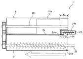
図2に示すように、本実施形態の画像形成装置は、感光体2上から除去された廃トナーを搬送する搬送手段として、廃トナー搬送スクリュ23と、廃トナー搬送経路24を備えている。感光体2上から除去された廃トナーは、感光体近傍の廃トナー搬送経路24a内を廃トナー搬送スクリュ23により、屈曲しながら図中の矢印aに示す方向に搬送される。廃トナー搬送スクリュ23の搬送方向下流の末端には、現像剤回収部9に廃トナーを廃出する廃トナー排出口24cを有する廃トナー排出部24bを備えている。廃トナー搬送スクリュ23によって廃トナー排出部24bまで搬送された廃トナーは、廃トナー排出口24cから現像剤回収部9へ排出される。
Next, the
FIG. 2 is an explanatory diagram of a waste
As shown in FIG. 2, the image forming apparatus of the present embodiment includes a waste
詳しくは、本実施形態の廃トナー搬送経路24は、搬送経路の途中に2つの屈曲部を有している。この2つの屈曲部のうち第一の屈曲部24dは、感光体2の周面を感光体2の軸方向に沿って延びる感光体近傍の廃トナー搬送経路24aが、感光体2の幅を超えた位置であるプロセスカートリッジ1の端部の位置で、重力方向斜め上に向かって略直角に曲がっている。もう一方の屈曲部である第二の屈曲部24eは、第一の屈曲部24dから重力方向斜め上に向かって延び、トナーカートリッジ7の現像剤回収部9の上面を越えた位置で、トナーカートリッジ7の長手方向中心に向かって略直角に屈曲している。この搬送経路は、第二屈曲部24eから感光体2の軸線方向に延び、廃トナー搬送方向下流の末端に廃トナー排出部24bを有している。
More specifically, the waste
本実施形態の廃トナー搬送経路24は、搬送経路の有する屈曲部をいずれも曲部で形成し、感光体2近傍の廃トナー搬送経路24aから廃トナー排出口24cまでの搬送経路を1本の搬送経路で形成している。これにより、屈曲部を有する搬送経路を直線状の複数の搬送経路を略直角につなぎ合わせることで構成した場合と比べて、廃トナー搬送経路の廃トナー詰まりや、屈曲部での廃トナー漏れが防止することができる。
In the waste
次に、本実施形態に係るトナーカートリッジ7について説明する。
まず、従来のトナーカートリッジ507の構成について説明する。
図10は、従来のトナーカートリッジ507の構成について説明する図である。
図11は、図10に示す従来のトナーカートリッジ507に廃トナーが充填された様子を示す説明図である。なお、従来のトナーカートリッジ507において、図1に基づき説明した画像形成装置100の備えるトナーカートリッジ7と同様な部分には同じ符号を付し、説明を省略する。
Next, the
First, the configuration of the
FIG. 10 is a diagram illustrating a configuration of a
FIG. 11 is an explanatory diagram showing a state where the
図10に示すように、従来のトナーカートリッジ507は、現像剤収容部8の下方に現像剤回収部9が位置している。また、現像剤回収部9内に廃トナー搬送手段であるスクリュ25を備え、このスクリュ25によって廃トナー排出口24cから排出された廃トナーを、現像剤回収部9内で廃トナー排出口24cから離れる方向に搬送する。
また、従来のトナーカートリッジ507では、現像剤収容部8の側方から現像剤収容部8内に向かって廃トナーが搬送されており、廃トナー排出口24cから排出される廃トナーを現像剤回収部9に受け入れための廃トナー受け入れ口9bが、現像剤回収部9の上面9aよりも低い位置に配置されている。このため、現像剤回収部9の廃トナー受け入れ口9bまで廃トナーが充填された状態では、現像剤回収部9の廃トナー回収効率が次のようになる。すなわち、図11に示すように、廃トナー受け入れ口9bの左側に廃トナーTが充填できないデッドスペース(以下、単に「デットスペース」という)が発生し、このデットスペースの分だけ現像剤回収部9の廃トナー回収効率が下がってしまう。
As shown in FIG. 10, in a
Further, in the
本実施形態のトナーカートリッジ7は、現像剤収容部8、現像剤回収部9、及び、廃トナー受け入れ口と備え、トナーカートリッジ7が画像形成装置100にセットされた際に、トナー受け入れ口が次のような位置になるように構成されている。すなわち、現像剤回収部9の内壁の上面となる箇所に前記廃トナー受け入れ口が配置されるように構成している。これにより、本実施形態においては、現像剤回収部9の廃トナー受け入れ口まで廃トナーが充填された状態において、廃トナー受け入れ口近傍にも廃トナーを充填することが可能となる。したがって、図11に示す従来のトナーカートリッジ507のように、廃トナー受け入れ口9bが現像剤回収部9の上面9aよりも低い位置に配置されたトナーカートリッジ507で生じていた、廃トナーTが充填できないデッドスペースをなくすことができる。このため、従来のトナーカートリッジよりも廃トナー収容量が増え、廃トナーの充填効率を高めることができる。
また、廃トナー収容量の増加によって、廃トナー収容部を従来よりも小さくすることができる。
The
Further, by increasing the waste toner storage amount, the waste toner storage unit can be made smaller than before.
[実施例1]
次に、本実施形態に係るトナーカートリッジ7の第一の実施例(以下、実施例1という)について説明する。
[Example 1]
Next, a first example (hereinafter, referred to as Example 1) of the
図3は、本実施形態に係るトナーカートリッジ7の構成の一例を示す概略構成図である。
図4は、図3に示すトナーカートリッジ7に廃トナーを充填した様子を示す説明図である。
本実施例のトナーカートリッジ7においては、図3に示すように、現像剤収容部8の側方から現像剤収容部8内に向かって廃トナーが搬送されており、現像剤回収部9の上面9aに廃トナー受け入れ口9bが設けられている。さらに、現像剤回収部9の廃トナー受け入れ口9bの直上に、廃トナー搬送経路24の廃トナー排出部24bが有する廃トナー排出口24cが位置している。このように、本実施例のトナーカートリッジは、現像剤回収部9の上面9aよりも上方に廃トナー受け入れ口9bが配置された構成となっている。
FIG. 3 is a schematic configuration diagram illustrating an example of the configuration of the
FIG. 4 is an explanatory view showing a state in which the
In the
これにより、図4に示すように、現像剤回収部9の廃トナー受け入れ口まで廃トナーが充填された状態において、廃トナー受け入れ口9c近傍にも廃トナーを充填することが可能となる。したがって、図11に示す従来のトナーカートリッジよりも廃トナー収容量が増え、廃トナーの充填効率を高めることができる。また、廃トナー収容量の増加によって、廃トナー収容部を従来よりも小さくすることができる。 Thereby, as shown in FIG. 4, in a state where the waste toner is filled up to the waste toner receiving port of the developer collecting section 9, it is possible to fill the vicinity of the waste toner receiving port 9c with the waste toner. Therefore, the amount of waste toner accommodated can be increased as compared with the conventional toner cartridge shown in FIG. Further, by increasing the waste toner storage amount, the waste toner storage unit can be made smaller than before.
さらにまた、本実施例のトナーカートリッジ7においては、廃トナー排出口24cの直下にスクリュ25の廃トナーを搬送する搬送部である羽部材25aが配置されている。これにより、廃トナー排出口24cから落下した廃トナーを滞りなく現像剤回収部9の奥に搬送することができる。
Furthermore, in the
[実施例2]
次に、本実施形態に係るトナーカートリッジの第二の実施例(以下、実施例2という)について説明する。
図5は、本実施形態に係るトナーカートリッジの他の構成の一例を示す概略構成図である。
なお、図5に示すトナーカートリッジ27は、トナーカートリッジ27の備える現像剤収容部8、及び現像剤回収部9の配置が異なる以外は、図3に基づき説明した実施例1のトナーカートリッジ7と同様の構成である。このため、実施例1のトナーカートリッジ7と同様な部分には同じ符号を付し、説明を省略する。
[Example 2]
Next, a second example (hereinafter, referred to as Example 2) of the toner cartridge according to the present embodiment will be described.
FIG. 5 is a schematic configuration diagram illustrating an example of another configuration of the toner cartridge according to the present embodiment.
The
図5に示すように、本実施例のトナーカートリッジ27は、現像剤回収部9の下方に現像剤収容部8が位置し、現像剤回収部9の上面9aに廃トナー受け入れ口9bが設けられている。さらに、現像剤回収部9の廃トナー受け入れ口9bの直上に、廃トナー搬送経路24の廃トナー排出部24bが有する廃トナー排出口24cが位置している。
このように、現像剤回収部9の上面9aよりも上方に廃トナー受け入れ口9bが配置されていることで、実施例1のトナーカートリッジ7と同様の理由で、廃トナー排出口24cの近傍に廃トナーTが充填できないデッドスペースを発生させることなく、廃トナー収容部の廃トナー回収効率を高めることができる。
As shown in FIG. 5, in the
As described above, since the waste
[実施例3]
次に、本実施形態に係るトナーカートリッジの第三の実施例(以下、実施例3という)について説明する。
図6は、本実施形態に係るトナーカートリッジのさらに他の構成の一例を示す概略構成図である。
なお、図6に示すトナーカートリッジ37は、トナーカートリッジ37の備える現像剤収容部8、及び現像剤回収部9の配置が異なる以外は、図3に基づき説明した実施例1のトナーカートリッジ7と同様の構成である。このため、実施例1のトナーカートリッジ7と同様な部分には同じ符号を付し、説明を省略する。
[Example 3]
Next, a third example (hereinafter, referred to as Example 3) of the toner cartridge according to the present embodiment will be described.
FIG. 6 is a schematic configuration diagram illustrating an example of still another configuration of the toner cartridge according to the present embodiment.
The
図6に示すように、本実施例のトナーカートリッジ37は、現像剤回収部9と現像剤収容部8とがプロセスカートリッジの長手方向で並列し、現像剤回収部9の上面9aに廃トナー受け入れ口9bが設けられている。さらに、現像剤回収部9の廃トナー受け入れ口9bの直上に、廃トナー搬送経路24の廃トナー排出部24bが有する廃トナー排出口24cが位置しており、現像剤回収部9の上面9aよりも上方に廃トナー排出口24cが配置された構成となっている。このように、現像剤回収部9の上面9aよりも上方に廃トナー受け入れ口9bが配置されていることで、実施例1のトナーカートリッジ7と同様の理由で、廃トナー排出口24cの近傍に廃トナーTが充填できないデッドスペースを発生させることなく、廃トナー収容部の廃トナー回収効率を高めることができる。
As shown in FIG. 6, in the
なお、図6では現像剤回収部9と現像剤収容部8がトナーカートリッジの長手方向で並列している例について説明したが、次のような構成でも良い。すなわち、トナーカートリッジの短手方向で現像剤回収部9と現像剤収容部8とが並列している場合など、現像剤回収部9と現像剤収容部8とがトナーカートリッジの短手方向に並列した構成としてもよい。この場合でも、廃トナー受け入れ口9bを現像剤回収部9の上面9aよりも上方に配置することで、廃トナー排出口の近傍に生じるデッドスペースを少なくすることができ、廃トナー収容部の廃トナー回収効率を高めることができる。
Although FIG. 6 illustrates an example in which the developer collection unit 9 and the
また、本実施例で使用するトナーは、例えば、粉砕トナーもしくは重合トナー100部に対して、疎水シリカRY50(アイロジル製)を2部添加し、20[リットル]ヘンシェルミキサーで周速40[m/s]、5分間の混合処理を行ない、その後、目開き75[ミクロン]の篩で篩って得たトナーとする。 The toner used in this embodiment is, for example, 100 parts of pulverized toner or polymerized toner, 2 parts of hydrophobic silica RY50 (manufactured by IRODIL) is added, and the peripheral speed is 40 [m / m] by a 20 [liter] Henschel mixer. s] The mixture is mixed for 5 minutes, and then sieved with a sieve having an opening of 75 [micron] to obtain a toner.
[実施例4]
次に、本実施形態に係るトナーカートリッジの第四の実施例(以下、実施例4という)について説明する。
まず、本実施例における廃トナー搬送経路について説明する。
なお、本実施例に係る廃トナーの搬送経路の基本的な構成については、図2を用いて説明した廃トナーの搬送経路と略同様なので説明は省略する。
本実例における搬送手段である廃トナー搬送スクリュ23は、曲折自在なトナー搬送部材であるフレキシブルスクリュである。この廃トナー搬送スクリュ23は、感光体2の幅を超えた位置であるトナーカートリッジの端部の位置で略直角に曲がり、重力方向斜め上に廃トナーを搬送する。そして、高さ方向においてトナーカートリッジの現像剤回収部9の上面を越えた位置で略直角に曲がり、廃トナー排出部24bの末端に位置する廃トナー排出口24cまで廃トナーを搬送する。
[Example 4]
Next, a fourth example (hereinafter, referred to as Example 4) of the toner cartridge according to the present embodiment will be described.
First, a description will be given of the waste toner transport path in the present embodiment.
Note that the basic configuration of the waste toner transport path according to the present embodiment is substantially the same as the waste toner transport path described with reference to FIG.
The waste
なお、トナーカートリッジの長手方向は感光体軸と略平行であり、前記感光体幅を越えた位置とは、トナーカートリッジの端部と同じ位置である。すなわち、廃トナー搬送スクリュ23であるフレキシブルスクリュはトナーカートリッジの端部で略直角に曲がっている。
このように、廃トナー搬送スクリュ23として、コイルやエラストマーゴム等で構成された曲折自在なスクリュを使用することで、一本のスクリュにより複雑な廃トナー搬送経路を構成できる。このため、廃トナー搬送経路の廃トナー詰まりや、屈曲部での廃トナー漏れが防止できる。
The longitudinal direction of the toner cartridge is substantially parallel to the axis of the photoconductor, and the position exceeding the width of the photoconductor is the same position as the end of the toner cartridge. That is, the flexible screw serving as the waste
As described above, by using a bendable screw made of a coil, an elastomer rubber, or the like as the waste
次に、本実例のトナーカートリッジについて説明する。
ユーザーによる消耗品の交換や購入の手間を省くために、画像形成装置の消耗品であるトナーカートリッジの交換頻度を少なくしようとした場合、従来よりもトナーカートリッジを大容量化する必要がある。また、大容量化は低ランニングコスト化にも繋がる。
また、トナーカートリッジの大容量化を行う際、トナー収容部の容量を従来品よりも増加させるとともに、現像剤回収部についても収容量の増加を図る必要がある。
Next, the toner cartridge of this example will be described.
In order to reduce the frequency of replacing the toner cartridge, which is a consumable item of the image forming apparatus, in order to save the user from having to replace or purchase the consumable item, it is necessary to increase the capacity of the toner cartridge as compared with the related art. In addition, an increase in capacity leads to a reduction in running cost.
In addition, when increasing the capacity of the toner cartridge, it is necessary to increase the capacity of the toner storage unit as compared with the conventional product, and to increase the storage amount of the developer collection unit.
本実施例のトナーカートリッジは、大容量のトナーカートリッジである。このトナーカートリッジは、大容量の現像剤収容部と、この現像剤収容部の下方に位置する現像剤回収部とを備えている。
現像剤収容部は、第一収容領域と第二収容領域とに分かれており、それぞれの領域に対応した2つのアジテーターであるトナー攪拌手段を有している。また、現像剤収容部の下面はトナー攪拌手段の回転軌跡に対応した湾曲形状となっている。
このように、現像剤収容部の下面に湾曲形状を形成することで、現像剤収容部の内壁における下面と、トナー攪拌手段との隙間を小さくし、現像剤収容部内の攪拌効率を上げることが可能となる。これにより、トナー容量が大容量化しても十分にトナーを攪拌することができ、トナー収容部の大容量化が可能となる。
The toner cartridge of this embodiment is a large-capacity toner cartridge. This toner cartridge includes a large-capacity developer storage section and a developer recovery section located below the developer storage section.
The developer accommodating section is divided into a first accommodating area and a second accommodating area, and has toner agitating means as two agitators corresponding to each area. The lower surface of the developer accommodating portion has a curved shape corresponding to the rotation locus of the toner stirring means.
Thus, by forming a curved shape on the lower surface of the developer accommodating portion, the gap between the lower surface on the inner wall of the developer accommodating portion and the toner stirring means can be reduced, and the stirring efficiency in the developer accommodating portion can be increased. It becomes possible. Thereby, even if the toner capacity is increased, the toner can be sufficiently stirred, and the capacity of the toner storage unit can be increased.
また、本実施例において現像剤収容部は、2つの収容領域のうち感光体2に対して離れた領域ほど、該領域の下端の位置が重力方向上方に位置する構成としている。これにより、トナーを感光体2に向かってより搬送しやすくすることができ、感光体2へのトナーの搬送効率をあげることができる。
Further, in the present embodiment, the developer accommodating portion is configured such that the lower the position of the lower end of the region is in the direction of gravity, the farther away from the
本実施例において、現像剤収容部の下方に位置する現像剤回収部は、現像剤収容部の大容量化に対応して大容量化した構成としている。このように、現像剤収容部の及び現像剤回収部を大容量化が可能となることで、大容量のトナーカートリッジを構成することができる。これにより、トナー収容器の交換の頻度を減らすことができ、低ランニングコスト化が実現できる。
なお、本実例のトナーカートリッジとしては、現像剤収容部の構成と同様に、現像剤回収部の収容領域を2つに分けた構成としても良く、回収効率が満足できれば1つの収容領域としても良い。また、現像剤収容部及び現像剤回収部のいずれも複数の収容領域を設けた構成とし、よりトナーカートリッジの大容量化を実現しても良い。
In the present embodiment, the developer collecting section located below the developer accommodating section is configured to have a large capacity corresponding to the large capacity of the developer accommodating section. As described above, the capacity of the developer accommodating portion and the developer collecting portion can be increased, so that a large-capacity toner cartridge can be configured. As a result, the frequency of replacement of the toner container can be reduced, and the running cost can be reduced.
Note that the toner cartridge of this example may have a configuration in which the storage area of the developer recovery section is divided into two similarly to the configuration of the developer storage section, and may be one storage area if the recovery efficiency is satisfied. . Further, each of the developer accommodating section and the developer collecting section may be provided with a plurality of accommodating areas, and the capacity of the toner cartridge may be further increased.
次に、実施例4におけるトナーカートリッジの廃トナー排出口の位置について説明する。
特許文献2に記載のトナーカートリッジは、トナーカートリッジの上方に廃トナー収容部、下方にトナー収容部を配置している。また、廃トナー搬送経路の廃トナー収容部側の末端(本実施形態における廃トナー排出部24b)をトナーカートリッジの比較的上部に配置しているため、廃トナーを重力に逆らってほぼ垂直に上方搬送する必要があった。また搬送経路が長くなるため、廃トナー搬送効率が悪くなるとともに、廃トナーの詰まりや漏れが問題になっていた。
Next, the position of the waste toner outlet of the toner cartridge according to the fourth embodiment will be described.
The toner cartridge described in
本実例におけるトナーカートリッジでは、現像剤収容部の下方に現像剤回収部を配置し、現像剤回収部内に廃トナーを排出する廃トナー排出口を有する廃トナー排出部の少なくとも一部が、現像剤収容部の外壁における下面の最下端より上方であり、現像剤収容部のケーシング外壁における最上端よりも下方に位置している。
このように、廃トナー排出部をトナーカートリッジの高さ方向のできるだけ低い位置に配置することで、特許文献2に記載のトナーカートリッジと比べて、廃トナーを重力に逆らって上方に搬送する必要性を軽減でき、廃トナー搬送効率を良くすることができる。また、廃トナー搬送経路を短くすることができるので、廃トナー搬送経路内での廃トナーの詰まりや漏れを防止することができる
In the toner cartridge according to the present embodiment, a developer collection unit is disposed below the developer storage unit, and at least a part of the waste toner discharge unit having a waste toner discharge port for discharging waste toner into the developer collection unit includes a developer. It is located above the lowermost end of the lower surface of the outer wall of the storage section and below the uppermost end of the outer wall of the casing of the developer storage section.
By arranging the waste toner discharge section as low as possible in the height direction of the toner cartridge, it is necessary to transport the waste toner upward against gravity as compared with the toner cartridge described in
また、本実施例のトナーカートリッジは、現像剤収容部の2つの収容領域の境界近傍に廃トナー排出口が来るように廃トナー排出部を配置している。
図3を用いて説明した実施例1のトナーカートリッジの構成では、廃トナー排出部が現像剤収容部8側に配置されている。このため、現像剤収容部8内に配置されているトナー攪拌手段26の攪拌部材26aが、廃トナー排出部24bの設置箇所と接触しないように、トナー収容部8の側壁から図中矢印Xで示す長さ分短くしている。したがって、実施例1のトナーカートリッジ7では、トナー収容部8の側壁から図中矢印Xで示す長さ分までのトナーが攪拌できない。
Further, in the toner cartridge of the present embodiment, the waste toner discharge unit is arranged such that the waste toner discharge port is located near the boundary between the two storage regions of the developer storage unit.
In the configuration of the toner cartridge according to the first embodiment described with reference to FIG. 3, the waste toner discharging unit is disposed on the
本実施例によれば、現像剤収容部と現像剤回収部との間であって、境界近傍に廃トナー排出部が位置するように廃トナー排出部を配置している。これにより、現像剤収容部内における各トナー攪拌手段の攪拌部材の軌跡を避けた位置に廃トナー排出部を設置することが可能となる。このため、現像剤収容部内における各トナー攪拌手段の攪拌部材の長さを短くすることなく、廃トナー排出部との接触を回避することが可能となる。したがって、現像剤収容部内のトナーの攪拌効率を下げることなく、廃トナーの回収率を向上させることができる。
なお、本実施例においては廃トナー排出部の外壁が現像剤収容部の内壁における下面である湾曲形状の最下端より完全に上方に位置する構成としたが、本実施例の構成としてはこれに限らない。例えば、廃トナー排出部の外周壁の一部が現像剤収容部における内壁の下面である湾曲形状の最下端より上方に配置してあればよい。
According to the present embodiment, the waste toner discharge unit is disposed between the developer storage unit and the developer collection unit such that the waste toner discharge unit is located near the boundary. This makes it possible to install the waste toner discharge unit at a position in the developer accommodating unit that avoids the trajectory of the stirring member of each toner stirring unit. For this reason, it is possible to avoid contact with the waste toner discharge unit without shortening the length of the stirring member of each toner stirring unit in the developer accommodating unit. Therefore, the recovery rate of the waste toner can be improved without lowering the stirring efficiency of the toner in the developer accommodating section.
In the present embodiment, the outer wall of the waste toner discharging unit is located completely above the lowermost end of the curved shape, which is the lower surface of the inner wall of the developer accommodating unit. Not exclusively. For example, it is only necessary that a part of the outer peripheral wall of the waste toner discharging section is disposed above the lowermost curved lower end of the inner wall of the developer accommodating section.
[実施形態2]
次に、本発明を大容量のトナーカートリッジ57を備えるプロセスカートリッジに適用した第二の実施形態(以下、実施形態2という)について説明する。
図7は、実施形態2に係るプロセスカートリッジ51の構成の一例を示す概略構成図である。
図7に示すプロセスカートリッジ51の基本的な構成は、図1に基づき説明した実施形態1のプロセスカートリッジ1と略同様であるため、同様な部分には同じ符号を付し、説明を省略する。また、本実施例に係るプロセスカートリッジにおける廃トナーの搬送経路の基本的な構成については、実施形態1の実施例4について説明した廃トナーの搬送経路と略同様なので説明を省略する。
[Embodiment 2]
Next, a second embodiment (hereinafter, referred to as a second embodiment) in which the present invention is applied to a process cartridge having a large-
FIG. 7 is a schematic configuration diagram illustrating an example of a configuration of the
The basic configuration of the
まず、本実施形態のトナーカートリッジ57について説明する。
なお、本実施形態のトナーカートリッジ57の基本的な構成は、図3に基づき説明した実施形態1のトナーカートリッジ7と略同様である。
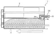
図7に示すように、本実施例のプロセスカートリッジ51は、大容量のトナーカートリッジ57を備えている。このトナーカートリッジ57は、大容量の現像剤収容部58と、この現像剤収容部58の下方に位置する現像剤回収部59とを備えている。
本実施形態のトナーカートリッジ57の現像剤収容部58は、第一収容領域58aと第二収容領域58bとに分かれており、それぞれの領域に対応した2つのアジテーターであるトナー攪拌手段26A,26Bを有している。また、現像剤収容部58の下面はトナー攪拌手段26の回転軌跡に対応した湾曲形状58Ya,58Ybとなっている。
First, the
Note that the basic configuration of the
As shown in FIG. 7, the
The
このように、現像剤収容部58の下面に湾曲形状58Ya,58Ybを形成することで、現像剤収容部58の下面における内壁と、トナー攪拌手段26A,26Bとの隙間を小さくし、現像剤収容部58内の攪拌効率を上げることができる。これにより、トナー収容部が大容量化しても十分にトナーを攪拌することができる。
As described above, by forming the curved shapes 58Ya and 58Yb on the lower surface of the
また、本実施形態において現像剤収容部58は、2つの収容領域58a,58bのうち感光体2に対して離れた領域ほど、該領域の下端の位置が重力方向上方に位置する構成となっている。具体的には、感光体2から離れた位置にある第二収容領域58bのケーシングの下端が、第一収容領域58aのケーシングの下端よりも重力方向上方に位置している。これにより、トナーを感光体2に向かってより搬送しやすくすることができ、感光体2へのトナーの搬送効率をあげることができる。
Further, in the present embodiment, the
現像剤収容部58の下方に位置する現像剤回収部59は、現像剤収容部58の大容量化に対応して大容量化した構成となっている。このように、本実施形態のトナーカートリッジ57においては、トナーカートリッジ57を大容量のトナーカートリッジとして構成することで、トナー収容器の交換の頻度を減らすことができ、低ランニングコスト化が実現できる。
The
なお、本実施形態のトナーカートリッジとしては、次のような構成としてもよい。すなわち、現像剤回収部59の収容領域は、現像剤収容部58と同様に2つの収容領域を設けた構成としても良く、回収効率が満足できれば1つの収容領域としても良い。また、現像剤収容部58及び現像剤回収部59のいずれも2つ以上の複数の収容領域を設けた構成とし、よりトナーカートリッジの大容量化を実現しても良い。
The toner cartridge according to the present embodiment may have the following configuration. That is, the storage area of the
次に、トナーカートリッジ57の廃トナー排出口の位置について説明する。
従来のトナーカートリッジは廃トナー搬送路を形成する搬送経路形成部材の搬送方向下流側末端(本実施形態における廃トナー排出部24b)が、次のような位置に配置されていた。すなわち、図7に示すトナーカートリッジ57の現像剤回収部59内であって、現像剤収容部58の内壁の下面における最下端より下方に配置されていた。
Next, the position of the waste toner outlet of the
In the conventional toner cartridge, the downstream end (the waste
本実施形態におけるトナーカートリッジ57では、現像剤収容部58の下方に現像剤回収部59を配置している。また、現像剤回収部59内に廃トナーを排出する廃トナー排出口を有する廃トナー排出部24bが、現像剤収容部58のケーシング外壁における下面の最下端より上方であり、かつ、現像剤収容部58のケーシング外壁における最上端よりも下方に位置している。具体的には、第一収容領域58aの下面である湾曲形状58Yaの最下端より上方であり、第二収容領域58bの下面である湾曲形状58Ybの最下端よりも下方に位置している。
In the
このように、廃トナー排出部24bを、現像剤収容部58のケーシング外壁における下面の最下端より上方に配置することで、廃トナー排出部24bが現像剤収容部58の内壁の下面における最下端より下方に配置されていたトナーカートリッジと比べて、現像剤回収部9の廃トナー回収効率を上げることができる。
詳しくは、本実施形態のトナーカートリッジ57では、廃トナー排出部24bをトナーカートリッジ57の高さ方向のできるだけ高い位置に配置している。これにより、廃トナー排出部24bが現像剤収容部58の内壁の下面における最下端より下方に配置されていたトナーカートリッジと比べて、現像剤回収部9の廃トナー収容率を上げることが可能となる。このため、現像剤回収部9の廃トナー回収効率を上げることができる。
As described above, by disposing the waste
More specifically, in the
さらにまた、本実施形態のトナーカートリッジ57は、現像剤収容部58の2つの収容領域(58a、58b)の境界58X近傍に廃トナー排出口24cが来るように廃トナー排出部24bを配置している。
図3を用いて説明した実施形態1の実施例1におけるトナーカートリッジの構成では、廃トナー排出部24bが現像剤収容部8側に配置されている。このため、現像剤収容部8内に配置されているトナー攪拌手段26の攪拌部材26aが、廃トナー排出部24bの設置箇所と接触しないように、トナー収容部8の側壁から図中矢印Xで示す長さ分短くしている。したがって、実施例1のトナーカートリッジ7では、トナー収容部8の側壁から図中矢印Xで示す長さ分までのトナーが攪拌できない。
Furthermore, in the
In the configuration of the toner cartridge according to Example 1 of Embodiment 1 described with reference to FIG. 3, the waste
本実施形態のトナーカートリッジ57では、現像剤回収部59内であって、現像剤収容部58内における複数の領域の境界58X近傍に廃トナー排出部24bが来るように廃トナー排出部24bを配置している。これにより、現像剤収容部58内の各トナー攪拌手段26A,26Bの攪拌部材の軌跡を避けた位置に廃トナー排出部24bを設置することが可能となる。このため、現像剤収容部58内の各トナー攪拌手段26A,26Bの攪拌部材の長さを短くすることなく、廃トナー排出部24bと接触を回避することが可能となる。したがって、現像剤収容部58内のトナーの攪拌効率を下げることなく、廃トナーの回収率を向上させることができる。
なお、本実施例においては廃トナー排出部24bの外壁が現像剤収容部58の内壁における下面である湾曲形状58Yaの最下端より完全に上方に位置する構成としたが、本実施例の構成としてはこれに限らない。例えば、廃トナー排出部24bの外周壁の一部が現像剤収容部58の内壁における下面である湾曲形状58Yaの最下端より上方に配置してあればよい。
In the
In the present embodiment, the outer wall of the waste
次に、本実施形態のトナーカートリッジ57を備える画像形成装置の構成の一例について説明する。
図8は、本実施形態に係る画像形成装置200の一例を示す概略構成図である。
図8に示すように、画像形成装置200は、モノクロ画像形成装置である。なお、図8に示す画像形成装置200の基本的な構成は、図1に基づき説明した画像形成装置100と略同様であるため、同様な部分には同じ符号を付し、説明を省略する。
Next, an example of a configuration of an image forming apparatus including the
FIG. 8 is a schematic configuration diagram illustrating an example of the
As shown in FIG. 8, the
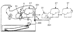
図9は、同画像形成装置200のプロセスカートリッジ51の着脱方法についての説明図である。
図9に示すように、本実施形態の画像形成装置200は、画像形成装置200本体の後部に設けられたカバー201が開閉可能となっている。また、カバー201を開いた状態にすると、リンク機構を介してLEDヘッドアレイ6が上方へ退避するようになっている。このように構成されていることで、カバー201を開いた状態で、LEDヘッドアレイ6との干渉を回避しつつプロセスカートリッジ51を後方(側方)から取り外すことが可能となっている。
FIG. 9 is a diagram illustrating a method of attaching and detaching the
As shown in FIG. 9, in the
また、本実施形態では、トナーカートリッジ57がプロセスカートリッジ51に装着された状態で、これらを一体的に装置本体200の後方(側方)から着脱可能となっている。さらに、トナーカートリッジ57は、プロセスカートリッジ51が装置本体200に装着された状態、及び取り外された状態のいずれにおいても、プロセスカートリッジ51に対して着脱可能となっている。
Further, in the present embodiment, in a state where the
以上に説明したものは一例であり、次の態様毎に特有の効果を奏する。
(態様A)
未使用トナーを収容する現像剤収容部8等のトナー収容部と、感光体2等の像担持体表面から回収された廃トナーを収容する現像剤回収部9等の廃トナー収容部と、前記廃トナーを前記廃トナー収容部に受け入れるための廃トナー受け入れ口9b等の廃トナー受け入れ口と備えるトナーカートリッジ7等のトナー収容器において、前記トナー収容器が画像形成装置100等の装置本体にセットされた際に、前記廃トナー収容部の内壁の上面9a等の上面となる箇所に前記廃トナー受け入れ口を配置することを特徴とする。
What has been described above is merely an example, and each embodiment has a specific effect.
(Aspect A)
A toner accommodating section such as a
本態様においては、実施形態1について説明したように、廃トナー受け入れ口9cまで現像剤回収部9内に廃トナーTを充填した際に、現像剤回収部9内の廃トナー受け入れ口9b近傍にも廃トナーを充填することが可能となる。したがって、図11に示す従来のトナーカートリッジ507のように、廃トナー受け入れ口9cが現像剤回収部9の上面9aよりも低い位置に配置されたトナーカートリッジで生じていた廃トナーTが充填できないデッドスペースを少なくすることができる。このため、従来のトナーカートリッジよりも廃トナー収容量が増え、廃トナーの充填効率を高めることができる。
In the present embodiment, as described in the first embodiment, when the waste toner T is filled in the developer collecting unit 9 up to the waste toner receiving port 9c, the waste toner T is located near the waste
(態様B)
態様Aにおいて、前記廃トナー収容部が前記トナー収容部の直下に位置し、廃トナー排出口24c等の前記廃トナー受け入れ口が、前記トナー収容部の内壁の下面における最下端よりも上方であって、前記トナー収容部の内壁の下面における最上端よりも下方に位置することを特徴とする。
(Aspect B)
In Aspect A, the waste toner storage section is located immediately below the toner storage section, and the waste toner receiving port such as the waste
本態様においては、実施例4について説明したように、現像剤収容部の下方に現像剤回収部を配置することで、廃トナー排出部24bをトナーカートリッジの高さ方向のできるだけ低い位置に配置することが可能となる。これにより、廃トナー収容部の下方にトナー収容部があるトナーカートリッジと比べて、廃トナーを重力に逆らって上方に搬送する必要性を軽減でき、廃トナー搬送効率を良くすることができる。また、廃トナー搬送経路を短くすることが可能となるので、廃トナー搬送経路内での廃トナーの詰まりや漏れを防止することができる。
In this aspect, as described in the fourth embodiment, by disposing the developer collecting section below the developer accommodating section, the waste
(態様C)
態様A又はBにおいて、前記トナー収容部は複数の領域により構成されており、前記複数の領域のそれぞれにトナーを攪拌または搬送する攪拌搬送手段を有し、前記トナー収容部のケーシング内壁における下面は前記攪拌搬送手段の回転軌跡に対応した湾曲形状であり、前記複数の領域のうち前記像担持体に対して離れた領域ほど、該領域の前記下面の位置が重力方向上方に位置することを特徴とする。
(Aspect C)
In the aspect A or B, the toner storage unit includes a plurality of regions, and includes a stirring and conveying unit that stirs or conveys the toner to each of the plurality of regions. A curved shape corresponding to the rotation locus of the stirring and conveying means, wherein the lower the position of the lower surface of the region is in the direction of gravity, the farther the region is from the image carrier among the plurality of regions. And
本態様においては、実施例4について説明したように、現像剤収容部の内壁における下面と、トナー攪拌手段との隙間を小さくし、現像剤収容部内の攪拌効率を上げることが可能となる。これにより、トナー容量が大容量化しても十分にトナーを攪拌することができ、トナー収容部の大容量化が可能となる。
また、感光体2から離れた位置にある第二収容領域の内壁の下端が、第一収容領域の内壁の下端よりも重力方向上方に位置していることで、トナーを感光体2に向かってより搬送しやすくすることができ、感光体2へのトナーの搬送効率をあげることが可能となる。したがって、大容量のトナーカートリッジを構成することが可能となり、トナー収容器の交換の頻度を減らすことができるため、低ランニングコスト化が実現できる。
In this aspect, as described in the fourth embodiment, it is possible to reduce the gap between the lower surface of the inner wall of the developer accommodating portion and the toner agitating means, and to increase the efficiency of agitation in the developer accommodating portion. Thereby, even if the toner capacity is increased, the toner can be sufficiently stirred, and the capacity of the toner storage unit can be increased.
Further, since the lower end of the inner wall of the second storage area located at a position away from the
(態様D)
態様Cにおいて、前記廃トナー受け入れ口が前記複数領域の境界近傍に配置されていることを特徴とする。
これにより、実施例4について説明したように、現像剤収容部内における各トナー攪拌手段の攪拌部材の軌跡を避けた位置に廃トナー排出部を設置することが可能となる。このため、現像剤収容部内の各トナー攪拌手段が備える攪拌部材の長さを短くすることなく、廃トナー排出部と各トナー攪拌手段との接触を回避することが可能となる。したがって、現像剤収容部内のトナーの攪拌効率を下げることなく、廃トナーの回収率を向上させることができる。
(Aspect D)
In the aspect C, the waste toner receiving port is arranged near a boundary between the plurality of areas.
As a result, as described in the fourth embodiment, it is possible to install the waste toner discharge unit at a position in the developer accommodating unit that avoids the trajectory of the stirring member of each toner stirring unit. For this reason, it is possible to avoid contact between the waste toner discharge unit and each toner stirring unit without reducing the length of the stirring member provided in each toner stirring unit in the developer accommodating unit. Therefore, the recovery rate of the waste toner can be improved without lowering the stirring efficiency of the toner in the developer accommodating section.
(態様E)
態様A〜Dいずれか一において、前記廃トナー収容部内に前記廃トナーを搬送するスクリュ25等の廃トナー搬送手段を有し、前記廃トナー受け入れ口の直下に前記廃トナーを搬送する前記廃トナー搬送手段の羽部材25a等の搬送部が位置することを特徴とする。
これにより、廃トナー排出口24cから落下した廃トナーを滞りなく現像剤回収部9の奥に搬送することができる。
(Aspect E)
In any one of Aspects A to D, the waste toner transport unit such as a
As a result, the waste toner dropped from the waste
(態様F)
少なくとも、未使用トナーを収容する現像剤収容部8等のトナー収容部と、感光体2等の像担持体表面から回収された廃トナーを収容する現像剤回収部9等の廃トナー収容部とを備えるトナーカートリッジ7等のトナー収容器と、前記廃トナーを前記トナー収容器まで搬送する廃トナーの搬送経路とを備えたプロセスカートリッジにおいて、前記搬送経路が、前記像担持体の周面を前記像担持体の軸方向に沿って延び、複数の屈曲部を経て、最終的に前記廃トナー収容部に向かって前記像担持体の軸方向に延び、前記トナー収容器として態様A〜Eいずれか一の態様のトナー収容器を用いる。
(Aspect F)
At least a toner storage unit such as a
(態様G)
態様Fにおいて、第一の屈曲部24d,第二の屈曲部24e等の前記複数の屈曲部が、前記像担持体の周面を前記像担持体の軸方向に沿って延び、前記像担持体の幅を超えた位置で前記廃トナー収容部に向かって略直角に屈曲する第一の屈曲部24d等の第一屈曲部と、前記第一屈曲部から重力方向斜め上に向かって延び、高さ方向における前記廃トナー収容部の上面を越えた位置で前記廃トナー収容部中心に向かって略直角に屈曲する第二の屈曲部24e等の第二屈曲部とを有することを特徴とする。
(Aspect G)
In the mode F, the plurality of bent portions such as a first bent portion 24d and a second
(態様H)
少なくとも、少なくとも、未使用トナーを収容するトナー収容部と、像担持体表面から回収された廃トナーを収容する廃トナー収容部とを備えるトナー収容器と、前記廃トナーを前記トナー収容器まで搬送する廃トナーの搬送経路とを備えたプロセスカートリッジにおいて、前記トナー収容部と前記廃トナー収容部とが一体的に着脱可能なトナーカートリッジであり、前記トナーカートリッジが本体装置から着脱自在であり、前記トナー収容器として態様A〜Eいずれか一の態様のトナー収容器を用いたことを特徴とする。
これにより、廃トナー収容部に対する廃トナーの回収効率を高めたトナー収容器を備えたプロセスカートリッジにおいて、メンテナンス性を向上することができる。
(Aspect H)
A toner container including at least a toner container that stores unused toner, a waste toner container that stores waste toner collected from the surface of the image carrier, and transporting the waste toner to the toner container A toner cartridge, wherein the toner storage unit and the waste toner storage unit are integrally detachable, and the toner cartridge is detachable from a main body device. The toner container according to any one of Aspects A to E is used as the toner container.
This makes it possible to improve the maintainability of the process cartridge including the toner container in which the efficiency of collecting the waste toner with respect to the waste toner storage unit is improved.
(態様I)
未使用トナーを収容する現像剤収容部8等のトナー収容部と、感光体2等の像担持体表面から回収された廃トナーを収容する現像剤回収部9等の廃トナー収容部とを備えるトナーカートリッジ7等のトナー収容器と、前記像担持体と、前記像担持体表面に形成された潜像を可視化する現像装置4等の現像手段とを備える画像形成装置100等の画像形成装置において、前記トナー収容器として態様B〜Eいずれか一の態様のトナー収容器を用いることを特徴とする。
これにより、廃トナー収容部に対する廃トナーの回収効率を高めた画像形成装置を提供することができる。
(Aspect I)
A toner storage unit such as a
Accordingly, it is possible to provide an image forming apparatus in which the collection efficiency of the waste toner in the waste toner storage unit is improved.
(態様J)
未使用トナーを収容する現像剤収容部58等のトナー収容部と、像担持体表面から回収された廃トナーを収容する現像剤回収部59等の廃トナー収容部と、搬送手段によって搬送されてきた前記廃トナーを前記廃トナー収容部に受け入れるための廃トナー受け入れ口9c等の廃トナー受け入れ口と備えるトナーカートリッジ57等のトナー収容器において、前記廃トナー収容部が前記トナー収容部の直下に位置し、前記廃トナー受け入れ口が、前記トナー収容部の下面を形成するケーシングの最下端よりも上であることを特徴とする。
(Aspect J)
The toner is conveyed by a conveyance unit, such as a toner storage unit such as a
本態様においては、実施形態2について説明したように、廃トナー排出部24bが現像剤収容部58の内壁における下面の最下端より下方に配置されていたトナーカートリッジと比べて、現像剤回収部9の廃トナー回収効率を上げることができる。
詳しくは、廃トナー排出部24bをトナーカートリッジ57の高さ方向のできるだけ高い位置に配置することで、現像剤収容部58の内壁における下面の最下端より下方に廃トナー排出部24bが配置されていたトナーカートリッジと比べて、現像剤回収部9の廃トナー収容率を上げることが可能となる。このため、現像剤回収部9の廃トナー回収効率を上げることができる。
In the present embodiment, as described in the second embodiment, the waste
More specifically, the waste
また、現像剤収容部58の下方に現像剤回収部59を配置することで、廃トナー排出部24bをトナーカートリッジ57の高さ方向のできるだけ低い位置に配置することが可能となる。これにより、廃トナー収容部の下方にトナー収容部があるトナーカートリッジと比べて、廃トナーを重力に逆らって上方に搬送する必要性を軽減でき、廃トナー搬送効率を良くすることができる。また、廃トナー搬送経路を短くすることが可能となるので、廃トナー搬送経路内での廃トナーの詰まりや漏れを防止することができる。
Further, by disposing the
1 実施形態1に係るプロセスカートリッジ
2 感光体
4 現像装置
7 トナーカートリッジ
8 現像剤収容部
9 現像剤回収部
9a 現像剤回収部のケーシングの上面
9b 現像剤受け入れ口
23 廃トナー搬送スクリュ
23 搬送手段
24 廃トナー搬送経路
24a 感光体近傍の廃トナー搬送経路
24b 廃トナー排出部
24c 廃トナー排出口
24d 第一屈曲部
24e 第二屈曲部
25 スクリュ
25a スクリュの羽部材
26A,26B トナー攪拌手段
26 トナー攪拌手段
26A,26B トナー攪拌手段
26a 攪拌部材
27 実施形態1の実施例2に係るトナーカートリッジ
37 実施形態1の実施例3に係るトナーカートリッジ
51 実施形態2に係るプロセスカートリッジ
57 実施形態2に係るトナーカートリッジ
58a 第一収容領域
58b 第二収容領域
58X 収容領域の境界
58Ya,58Yb 湾曲形状
100 実施形態1に係る画像形成装置
200 実施形態2に係る画像形成装置
T 廃トナー
1
Claims (9)
前記トナー収容器が装置本体にセットされた際に、前記廃トナー収容部の内壁の上面となる箇所に前記廃トナー受け入れ口を配置し、
前記廃トナー収容部が前記トナー収容部の直下に位置し、
前記廃トナー受け入れ口が、前記トナー収容部の内壁の下面における最下端よりも上方であって、前記トナー収容部の内壁の下面における最上端よりも下方に位置することを特徴とするトナー収容器。 A toner storage unit for storing unused toner, a waste toner storage unit for storing waste toner collected from the surface of the image carrier, and a toner having a waste toner receiving port for receiving the waste toner into the waste toner storage unit In the container,
When the toner container is set in the apparatus main body, the waste toner receiving port is disposed at a location that becomes an upper surface of an inner wall of the waste toner container,
The waste toner container is located immediately below the toner container,
The toner container, wherein the waste toner receiving port is located above the lowermost end of the lower surface of the inner wall of the toner container and lower than the uppermost end of the lower surface of the inner wall of the toner container. .
前記トナー収容器が装置本体にセットされた際に、前記廃トナー収容部の内壁の上面となる箇所に前記廃トナー受け入れ口を配置し、
前記トナー収容部は複数の領域により構成されており、前記複数の領域のそれぞれにトナーを攪拌または搬送する攪拌搬送手段を有し、前記トナー収容部の内壁の下面が前記攪拌搬送手段の回転軌跡に対応した湾曲形状であり、前記複数の領域の各領域の前記下面の位置が、前記複数の領域のうち前記像担持体に対して離れた領域ほど上方に位置し、
前記廃トナー受け入れ口が前記複数の領域の境界近傍に配置されていることを特徴とするトナー収容器。 A toner storage unit for storing unused toner, a waste toner storage unit for storing waste toner collected from the surface of the image carrier, and a toner having a waste toner receiving port for receiving the waste toner into the waste toner storage unit In the container,
When the toner container is set in the apparatus main body, the waste toner receiving port is disposed at a location that becomes an upper surface of an inner wall of the waste toner container,
The toner storage unit includes a plurality of regions, and has a stirring and conveying unit that stirs or conveys the toner to each of the plurality of regions, and a lower surface of an inner wall of the toner storage unit has a rotation locus of the stirring and conveying unit. The position of the lower surface of each of the plurality of regions, the position of the lower surface of each of the plurality of regions is located more upward in a region away from the image carrier of the plurality of regions,
The toner container, wherein the waste toner receiving port is disposed near a boundary between the plurality of areas.
Priority Applications (1)
| Application Number | Priority Date | Filing Date | Title |
|---|---|---|---|
| JP2015118769A JP6641613B2 (en) | 2015-06-11 | 2015-06-11 | Toner container, process cartridge, and image forming apparatus |
Applications Claiming Priority (1)
| Application Number | Priority Date | Filing Date | Title |
|---|---|---|---|
| JP2015118769A JP6641613B2 (en) | 2015-06-11 | 2015-06-11 | Toner container, process cartridge, and image forming apparatus |
Publications (3)
| Publication Number | Publication Date |
|---|---|
| JP2017003829A JP2017003829A (en) | 2017-01-05 |
| JP2017003829A5 JP2017003829A5 (en) | 2018-07-19 |
| JP6641613B2 true JP6641613B2 (en) | 2020-02-05 |
Family
ID=57751642
Family Applications (1)
| Application Number | Title | Priority Date | Filing Date |
|---|---|---|---|
| JP2015118769A Active JP6641613B2 (en) | 2015-06-11 | 2015-06-11 | Toner container, process cartridge, and image forming apparatus |
Country Status (1)
| Country | Link |
|---|---|
| JP (1) | JP6641613B2 (en) |
Family Cites Families (9)
| Publication number | Priority date | Publication date | Assignee | Title |
|---|---|---|---|---|
| JPS6386671U (en) * | 1986-11-25 | 1988-06-06 | ||
| JPS63298370A (en) * | 1987-05-29 | 1988-12-06 | Ricoh Co Ltd | Toner cartridge |
| JP3034579B2 (en) * | 1989-10-05 | 2000-04-17 | 株式会社リコー | Developer supply and recovery device |
| JPH0621050U (en) * | 1992-08-19 | 1994-03-18 | ブラザー工業株式会社 | Electrophotographic device |
| JP3840063B2 (en) * | 2001-04-27 | 2006-11-01 | キヤノン株式会社 | Process cartridge |
| JP3705364B2 (en) * | 2003-05-06 | 2005-10-12 | 富士ゼロックス株式会社 | Image forming apparatus, process cartridge and developing device used therefor |
| JP2008292729A (en) * | 2007-05-24 | 2008-12-04 | Konica Minolta Business Technologies Inc | Toner cartridge |
| JP4434309B1 (en) * | 2009-10-05 | 2010-03-17 | 富士ゼロックス株式会社 | Developer container and image forming apparatus |
| KR20110124603A (en) * | 2010-05-11 | 2011-11-17 | 삼성전자주식회사 | Toner cartridge and image froming apparatus having the same |
-
2015
- 2015-06-11 JP JP2015118769A patent/JP6641613B2/en active Active
Also Published As
| Publication number | Publication date |
|---|---|
| JP2017003829A (en) | 2017-01-05 |
Similar Documents
| Publication | Publication Date | Title |
|---|---|---|
| EP3109707B1 (en) | Powder container and image forming apparatus incorporating same | |
| KR101457760B1 (en) | Developer container and image forming device equipped with the same | |
| JPWO2013128844A1 (en) | Powder conveying apparatus and image forming apparatus | |
| JP4851823B2 (en) | Electrophotographic developer unit with special discharge port for developing material | |
| CN102591173A (en) | Developer container and image forming apparatus | |
| KR101457759B1 (en) | Developer container and image forming device equipped with the same | |
| JP4900467B2 (en) | Developer supply device | |
| JP5540142B2 (en) | Developer container and image forming apparatus to which the container is applied | |
| JP2020086132A (en) | Developer storage container, developer supply device, process cartridge, and image formation apparatus | |
| JP6641613B2 (en) | Toner container, process cartridge, and image forming apparatus | |
| JP2008129113A (en) | Developing device | |
| JP6664139B2 (en) | Developing device | |
| JP6069231B2 (en) | Developer container and image forming apparatus provided with the same | |
| JP2013148723A (en) | Toner storage container and image forming apparatus equipped with the same | |
| JP7009528B2 (en) | Developer | |
| JP5862340B2 (en) | Toner supply device and image forming apparatus | |
| JP5471541B2 (en) | Developing device, process cartridge, and image forming apparatus | |
| JP5504908B2 (en) | Development system and image forming apparatus | |
| JP3509476B2 (en) | Image forming device | |
| JP2016173560A (en) | Image forming unit and image forming apparatus | |
| JP2022036233A (en) | Development device | |
| JP5862339B2 (en) | Toner supply device and image forming apparatus | |
| JP2008122662A (en) | Developing device | |
| JP6237092B2 (en) | Developer | |
| JP5377564B2 (en) | Developer container and image forming apparatus to which the container is applied |
Legal Events
| Date | Code | Title | Description |
|---|---|---|---|
| A621 | Written request for application examination |
Free format text: JAPANESE INTERMEDIATE CODE: A621 Effective date: 20180531 |
|
| A521 | Written amendment |
Free format text: JAPANESE INTERMEDIATE CODE: A523 Effective date: 20180608 |
|
| A977 | Report on retrieval |
Free format text: JAPANESE INTERMEDIATE CODE: A971007 Effective date: 20190305 |
|
| A131 | Notification of reasons for refusal |
Free format text: JAPANESE INTERMEDIATE CODE: A131 Effective date: 20190315 |
|
| A521 | Written amendment |
Free format text: JAPANESE INTERMEDIATE CODE: A523 Effective date: 20190425 |
|
| A131 | Notification of reasons for refusal |
Free format text: JAPANESE INTERMEDIATE CODE: A131 Effective date: 20190719 |
|
| A521 | Written amendment |
Free format text: JAPANESE INTERMEDIATE CODE: A523 Effective date: 20190917 |
|
| TRDD | Decision of grant or rejection written | ||
| A01 | Written decision to grant a patent or to grant a registration (utility model) |
Free format text: JAPANESE INTERMEDIATE CODE: A01 Effective date: 20191129 |
|
| A61 | First payment of annual fees (during grant procedure) |
Free format text: JAPANESE INTERMEDIATE CODE: A61 Effective date: 20191212 |
|
| R151 | Written notification of patent or utility model registration |
Ref document number: 6641613 Country of ref document: JP Free format text: JAPANESE INTERMEDIATE CODE: R151 |