JP6636635B2 - System and method for mixed interference management - Google Patents
System and method for mixed interference management Download PDFInfo
- Publication number
- JP6636635B2 JP6636635B2 JP2018528010A JP2018528010A JP6636635B2 JP 6636635 B2 JP6636635 B2 JP 6636635B2 JP 2018528010 A JP2018528010 A JP 2018528010A JP 2018528010 A JP2018528010 A JP 2018528010A JP 6636635 B2 JP6636635 B2 JP 6636635B2
- Authority
- JP
- Japan
- Prior art keywords
- base station
- mixed interference
- interference
- downlink
- ues
- Prior art date
- Legal status (The legal status is an assumption and is not a legal conclusion. Google has not performed a legal analysis and makes no representation as to the accuracy of the status listed.)
- Active
Links
- 238000000034 method Methods 0.000 title claims description 54
- 238000004891 communication Methods 0.000 claims description 105
- 238000005259 measurement Methods 0.000 claims description 85
- 230000005540 biological transmission Effects 0.000 claims description 55
- 230000000116 mitigating effect Effects 0.000 claims description 25
- 230000015654 memory Effects 0.000 claims description 13
- 230000002829 reductive effect Effects 0.000 claims description 8
- 230000001172 regenerating effect Effects 0.000 claims description 8
- 238000012544 monitoring process Methods 0.000 description 14
- 230000006870 function Effects 0.000 description 12
- 238000001228 spectrum Methods 0.000 description 12
- 230000000694 effects Effects 0.000 description 10
- 230000008569 process Effects 0.000 description 10
- 238000010586 diagram Methods 0.000 description 9
- 238000005516 engineering process Methods 0.000 description 9
- 238000004458 analytical method Methods 0.000 description 8
- 238000012545 processing Methods 0.000 description 8
- 230000008901 benefit Effects 0.000 description 7
- 230000000875 corresponding effect Effects 0.000 description 6
- 238000013461 design Methods 0.000 description 6
- 230000008859 change Effects 0.000 description 5
- 230000011664 signaling Effects 0.000 description 5
- 230000001360 synchronised effect Effects 0.000 description 5
- 230000004044 response Effects 0.000 description 4
- 238000013459 approach Methods 0.000 description 3
- 230000009286 beneficial effect Effects 0.000 description 3
- 239000000835 fiber Substances 0.000 description 3
- 230000003287 optical effect Effects 0.000 description 3
- 230000008520 organization Effects 0.000 description 3
- 239000000523 sample Substances 0.000 description 3
- 230000006978 adaptation Effects 0.000 description 2
- 238000004422 calculation algorithm Methods 0.000 description 2
- 230000003993 interaction Effects 0.000 description 2
- 230000002452 interceptive effect Effects 0.000 description 2
- 230000007774 longterm Effects 0.000 description 2
- 238000000926 separation method Methods 0.000 description 2
- 230000008054 signal transmission Effects 0.000 description 2
- 230000001960 triggered effect Effects 0.000 description 2
- 101100048435 Caenorhabditis elegans unc-18 gene Proteins 0.000 description 1
- 230000009471 action Effects 0.000 description 1
- 230000001154 acute effect Effects 0.000 description 1
- 230000002411 adverse Effects 0.000 description 1
- 238000003491 array Methods 0.000 description 1
- 238000004364 calculation method Methods 0.000 description 1
- 239000000969 carrier Substances 0.000 description 1
- 230000001413 cellular effect Effects 0.000 description 1
- 238000006243 chemical reaction Methods 0.000 description 1
- 230000001427 coherent effect Effects 0.000 description 1
- 238000004590 computer program Methods 0.000 description 1
- 230000001276 controlling effect Effects 0.000 description 1
- 230000002596 correlated effect Effects 0.000 description 1
- 230000003111 delayed effect Effects 0.000 description 1
- 238000001514 detection method Methods 0.000 description 1
- 238000011161 development Methods 0.000 description 1
- 230000018109 developmental process Effects 0.000 description 1
- 238000005562 fading Methods 0.000 description 1
- 230000006872 improvement Effects 0.000 description 1
- 230000000977 initiatory effect Effects 0.000 description 1
- 238000005305 interferometry Methods 0.000 description 1
- 230000000670 limiting effect Effects 0.000 description 1
- 239000006249 magnetic particle Substances 0.000 description 1
- 238000010295 mobile communication Methods 0.000 description 1
- 238000012986 modification Methods 0.000 description 1
- 230000004048 modification Effects 0.000 description 1
- 230000036961 partial effect Effects 0.000 description 1
- 239000002245 particle Substances 0.000 description 1
- 238000005192 partition Methods 0.000 description 1
- 230000008929 regeneration Effects 0.000 description 1
- 238000011069 regeneration method Methods 0.000 description 1
- 230000001105 regulatory effect Effects 0.000 description 1
- 230000002441 reversible effect Effects 0.000 description 1
- 238000012552 review Methods 0.000 description 1
- 230000003595 spectral effect Effects 0.000 description 1
- 238000012549 training Methods 0.000 description 1
- 238000012546 transfer Methods 0.000 description 1
- 230000001755 vocal effect Effects 0.000 description 1
Images


Classifications
-
- H—ELECTRICITY
- H04—ELECTRIC COMMUNICATION TECHNIQUE
- H04W—WIRELESS COMMUNICATION NETWORKS
- H04W72/00—Local resource management
- H04W72/50—Allocation or scheduling criteria for wireless resources
- H04W72/54—Allocation or scheduling criteria for wireless resources based on quality criteria
- H04W72/541—Allocation or scheduling criteria for wireless resources based on quality criteria using the level of interference
-
- H—ELECTRICITY
- H04—ELECTRIC COMMUNICATION TECHNIQUE
- H04W—WIRELESS COMMUNICATION NETWORKS
- H04W72/00—Local resource management
- H04W72/50—Allocation or scheduling criteria for wireless resources
- H04W72/54—Allocation or scheduling criteria for wireless resources based on quality criteria
- H04W72/542—Allocation or scheduling criteria for wireless resources based on quality criteria using measured or perceived quality
Landscapes
- Engineering & Computer Science (AREA)
- Quality & Reliability (AREA)
- Computer Networks & Wireless Communication (AREA)
- Signal Processing (AREA)
- Mobile Radio Communication Systems (AREA)
Description
関連出願の相互参照
本出願は、2015年12月2日に出願された「SYSTEMS AND METHODS FOR MIXED INTERFERENCE MANAGEMENT」と題する米国仮特許出願第62/262,080号、および2016年3月18日に出願された「SYSTEMS AND METHODS FOR MIXED INTERFERENCE MANAGEMENT」と題する米国非仮特許出願第15/074,342号の利益を主張し、これらは両方とも、その全体が参照により本明細書に明確に組み込まれる。
CROSS REFERENCE TO RELATED APPLICATIONSThis application was filed on U.S. Provisional Patent Application No. 62 / 262,080 entitled `` SYSTEMS AND METHODS FOR MIXED INTERFERENCE MANAGEMENT '' filed No. 15 / 074,342, entitled "SYSTEMS AND METHODS FOR MIXED INTERFERENCE MANAGEMENT," both of which are expressly incorporated herein by reference in their entirety.
本開示の態様は、一般にワイヤレス通信システムに関し、より詳細には、混合干渉管理(Mixed Interference Management)に関する。本発明の実施形態は、混合干渉管理のためのジャミンググラフの生成および/または再生成を可能にし、それを行う。 Aspects of the present disclosure relate generally to wireless communication systems, and more particularly, to Mixed Interference Management. Embodiments of the present invention enable and do the generation and / or regeneration of jamming graphs for mixed interference management.
ワイヤレス通信ネットワークは、いくつかのユーザ機器(UE)のための通信をサポートすることができる、いくつかの基地局またはノードBを含み得る。UEは、ダウンリンクおよびアップリンクを介して基地局と通信し得る。ダウンリンク(または順方向リンク)は、基地局または他の第1のデバイス(たとえば、データソースデバイス)からUEまたは他の第2のデバイス(たとえば、データシンクデバイス)への通信リンクを指し、アップリンク(または逆方向リンク)は、UEまたは他の第2のデバイスから基地局または他の第1のデバイスへの通信リンクを指す。 A wireless communication network may include a number of base stations or Node Bs that can support communication for a number of user equipments (UEs). A UE may communicate with a base station via the downlink and uplink. Downlink (or forward link) refers to the communication link from a base station or other first device (e.g., a data source device) to a UE or other second device (e.g., a data sink device) and A link (or reverse link) refers to a communication link from a UE or other second device to a base station or other first device.
基地局は、ダウンリンク上でUEにデータおよび制御情報を送信することができ、かつ/または、アップリンク上でUEからデータおよび制御情報を受信することができる。ダウンリンク上で、基地局からの送信は、ネイバー基地局からの、または他のワイヤレス無線周波数(RF)送信機からの送信に起因する干渉を受ける場合がある。アップリンク上で、UEからの送信は、ネイバー基地局と通信する他のUEのアップリンク送信からの、または他のワイヤレスRF送信機からの干渉を受ける場合がある。この干渉は、ダウンリンクとアップリンクの両方において性能を低下させる場合がある。 A base station may transmit data and control information to the UE on the downlink and / or may receive data and control information from the UE on the uplink. On the downlink, transmissions from the base station may be subject to interference due to transmissions from neighbor base stations or from other wireless radio frequency (RF) transmitters. On the uplink, transmissions from the UE may be subject to interference from uplink transmissions of other UEs communicating with neighbor base stations or from other wireless RF transmitters. This interference may degrade performance on both the downlink and the uplink.
モバイルブロードバンドアクセスに対する需要が増加し続けるにつれて、より多くのUEが長距離ワイヤレス通信ネットワークにアクセスし、より多くの短距離ワイヤレスシステムが地域に展開されるのに伴って、干渉および輻輳ネットワークの可能性が高まっている。たとえば、従来の時分割複信(TDD)実装形態は、ダウンリンクサブフレームおよびアップリンクサブフレームの固定構成を利用しており、ダウンリンクおよびアップリンクのスケジューリングは、展開全体にわたって同期する。すなわち、システム全体は、そのような固定構成における基地局ダウンリンクおよびアップリンク通信のための特定のタイミングパターンに従う。そのような同期したダウンリンクおよびアップリンクのスケジューリング展開は、その比較的単純な展開および管理により、概して許容できるものになっている。具体的には、ダウンリンクおよびアップリンクの同期したスケジューリングの使用は、干渉シナリオをダウンリンクからダウンリンクへの干渉シナリオおよびアップリンクからアップリンクへの干渉シナリオに限定する。したがって、ダウンリンクからアップリンクへの干渉シナリオまたはアップリンクからダウンリンクへの干渉シナリオ(本明細書では、まとめておよび別個に混合干渉シナリオと呼ばれる)が回避され、そのような混合干渉シナリオのための干渉軽減が提供される必要はない。 As the demand for mobile broadband access continues to increase, as more UEs access long distance wireless communication networks and more short distance wireless systems are deployed in regions, the potential for interference and congestion networks Is growing. For example, conventional time division duplex (TDD) implementations utilize a fixed configuration of downlink and uplink subframes, and downlink and uplink scheduling are synchronized throughout the deployment. That is, the entire system follows a specific timing pattern for base station downlink and uplink communications in such a fixed configuration. Such synchronized downlink and uplink scheduling deployment is generally acceptable due to its relatively simple deployment and management. Specifically, the use of downlink and uplink synchronized scheduling limits interference scenarios to downlink to downlink interference scenarios and uplink to uplink interference scenarios. Thus, downlink-to-uplink interference scenarios or uplink-to-downlink interference scenarios (collectively and separately referred to herein as mixed interference scenarios) are avoided, and for such mixed interference scenarios Need not be provided.
以下では、説明する技術の基本的理解を与えるために本開示のいくつかの態様を要約する。この概要は、本開示のすべての企図された特徴の広範な概観ではなく、本開示のすべての態様の主要または重要な要素を識別するものでもなく、本開示のいずれかまたはすべての態様の範囲を定めるものでもない。その唯一の目的は、後で提示するより詳細な説明の前置きとして、本開示の1つまたは複数の態様のいくつかの概念を概要の形で提示することである。 The following summarizes some aspects of the present disclosure in order to provide a basic understanding of the described technology. This summary is not an extensive overview of all contemplated features of the disclosure, nor is it intended to identify key or critical elements of all aspects of the disclosure, but rather the scope of any or all aspects of the disclosure. It does not prescribe. Its sole purpose is to present some concepts of one or more aspects of the disclosure in a simplified form as a prelude to the more detailed description that is presented later.
本明細書の例示的な実装形態に従って、方法が提供される。いくつかの実装形態の方法は、基地局によって、基地局と通信している1つまたは複数のユーザ機器(UE)のうちの少なくとも1つからあるいは1つまたは複数の他の基地局から、1つまたは複数のUEおよび1つまたは複数の他の基地局のうちのそれぞれの報告側が受けたダウンリンクからアップリンクへの干渉またはアップリンクからダウンリンクへの干渉のうちの少なくとも1つに関する情報を含む混合干渉情報を受信するステップを含む。この方法は、基地局によって、報告された混合干渉情報を使用して、基地局と通信している1つまたは複数のUEのうちの少なくとも1つとの通信を管理するステップをさらに含む。 According to an example implementation herein, a method is provided. The method of some implementations includes: by a base station, from at least one of one or more user equipments (UEs) in communication with the base station, or from one or more other base stations, One or more UEs and one or more other base stations receive information on at least one of downlink-to-uplink interference or uplink-to-downlink interference received by a reporter of each. Receiving the mixed interference information. The method further includes managing communication with at least one of the one or more UEs communicating with the base station using the mixed interference information reported by the base station.
本明細書の例示的な実装形態に従って、装置が提供される。いくつかの実装形態の装置は、基地局によって、基地局と通信している1つまたは複数のユーザ機器(UE)のうちの少なくとも1つからあるいは1つまたは複数の他の基地局から、1つまたは複数のUEおよび1つまたは複数の他の基地局のうちのそれぞれの報告側が受けたダウンリンクからアップリンクへの干渉またはアップリンクからダウンリンクへの干渉のうちの少なくとも1つに関する情報を含む混合干渉情報を受信するための手段を含む。この装置は、基地局によって、報告された混合干渉情報を使用して、基地局と通信している1つまたは複数のUEのうちの少なくとも1つとの通信を管理するための手段をさらに含む。 An apparatus is provided according to an example implementation herein. The apparatus of some implementations may include, by a base station, at least one of one or more user equipments (UEs) in communication with the base station, or from one or more other base stations. One or more UEs and one or more other base stations receive information on at least one of downlink to uplink interference or uplink to downlink interference received by each reporter of the one or more other base stations. Means for receiving mixed interference information. The apparatus further includes means for using the mixed interference information reported by the base station to manage communication with at least one of the one or more UEs communicating with the base station.
本明細書の例示的な実装形態に従って、プログラムコードを記録した非一時的コンピュータ可読媒体が提供される。非一時的コンピュータ可読媒体のいくつかの実装形態のプログラムコードは、基地局によって、基地局と通信している1つまたは複数のユーザ機器(UE)のうちの少なくとも1つからあるいは1つまたは複数の他の基地局から、1つまたは複数のUEおよび1つまたは複数の他の基地局のうちのそれぞれの報告側が受けたダウンリンクからアップリンクへの干渉またはアップリンクからダウンリンクへの干渉のうちの少なくとも1つに関する情報を含む混合干渉情報を受信することをコンピュータに行わせるためのプログラムコードを含む。このプログラムコードは、基地局によって、報告された混合干渉情報を使用して、基地局と通信している1つまたは複数のUEのうちの少なくとも1つとの通信を管理することをコンピュータにさらに行わせる。 According to an exemplary implementation herein, a non-transitory computer readable medium having program code recorded thereon is provided. The program code of some implementations of the non-transitory computer-readable medium is transmitted by the base station from at least one or one or more of one or more user equipments (UEs) communicating with the base station. From one or more UEs and one or more other base stations, respectively, of the downlink-to-uplink interference or the uplink-to-downlink interference received by the reporter of each of the one or more other base stations. A program code for causing a computer to receive the mixed interference information including information on at least one of them. The program code further causes the computer to use the mixed interference information reported by the base station to manage communication with at least one of the one or more UEs communicating with the base station. Let
本明細書の例示的な実装形態に従って、少なくとも1つのプロセッサと、少なくとも1つのプロセッサに結合されたメモリとを有する装置が提供される。いくつかの実装形態の装置の少なくとも1つのプロセッサは、基地局によって、基地局と通信している1つまたは複数のユーザ機器(UE)のうちの少なくとも1つからあるいは1つまたは複数の他の基地局から、1つまたは複数のUEおよび1つまたは複数の他の基地局のうちのそれぞれの報告側が受けたダウンリンクからアップリンクへの干渉またはアップリンクからダウンリンクへの干渉のうちの少なくとも1つに関する情報を含む混合干渉情報を受信するように構成される。装置のこの少なくとも1つのプロセッサは、基地局によって、報告された混合干渉情報を使用して、基地局と通信している1つまたは複数のUEのうちの少なくとも1つとの通信を管理するようにさらに構成される。 According to an exemplary implementation herein, there is provided an apparatus having at least one processor and a memory coupled to the at least one processor. At least one processor of the apparatus of some implementations may include, by the base station, at least one of the one or more user equipments (UEs) in communication with the base station or one or more other ones. From the base station, at least one of downlink-to-uplink interference or uplink-to-downlink interference received by the respective reporter of one or more UEs and one or more other base stations. It is configured to receive mixed interference information including information about one. The at least one processor of the apparatus uses the mixed interference information reported by the base station to manage communication with at least one of the one or more UEs communicating with the base station. It is further configured.
上記では、以下の発明を実施するための形態がより良く理解され得るように、本開示による例の特徴および技術的利点についてかなり広く概説した。追加の特徴および利点について、以下で説明する。開示する概念および具体的な例は、本開示の同じ目的を実行するための他の構造を変更または設計するための基礎として容易に利用され得る。そのような等価な構成は、添付の特許請求の範囲から逸脱しない。本明細書で開示する概念の特性、それらの編成と動作方法の両方は、添付の図とともに検討されると、関連する利点とともに以下の説明からより良く理解されよう。図の各々は、例示および説明のために提供されるものであり、特許請求の範囲の限定の定義として提供されるものではない。 The foregoing has outlined rather broadly the features and technical advantages of examples in accordance with the present disclosure so that the following detailed description may be better understood. Additional features and advantages are described below. The disclosed concepts and specific examples can be readily utilized as a basis for modifying or designing other structures to perform the same purpose of the present disclosure. Such equivalent arrangements do not depart from the scope of the appended claims. The characteristics of the concepts disclosed herein, both their organization and the manner of operation, together with the associated advantages, will be better understood from the following description when considered in conjunction with the accompanying figures. Each of the figures is provided by way of illustration and description, and not as a limitation on the scope of the claims.
添付の図とともに本発明の特定の例示的な実施形態の以下の説明を検討すれば、本発明の他の態様、特徴、および実施形態が当業者に明らかとなろう。本発明の特徴について、以下のいくつかの実施形態および図に対して説明する場合があるが、本発明のすべての実施形態は、本明細書で説明する有利な特徴のうちの1つまたは複数を含むことができる。言い換えれば、1つまたは複数の実施形態について、いくつかの有利な特徴を有するものとして説明する場合があるが、そのような特徴のうちの1つまたは複数はまた、本明細書で説明する本発明の様々な実施形態に従って使用され得る。同様に、例示的な実施形態について、デバイス、システム、または方法の実施形態として以下で説明する場合があるが、そのような例示的な実施形態は、様々なデバイス、システム、および方法において実装され得ることを理解されたい。 Other aspects, features, and embodiments of the invention will be apparent to those skilled in the art from a review of the following description of certain exemplary embodiments of the invention, when taken in conjunction with the accompanying drawings. While features of the present invention may be described with respect to the following several embodiments and figures, all embodiments of the present invention may include one or more of the advantageous features described herein. Can be included. In other words, one or more embodiments may be described as having some advantageous features, but one or more of such features may also be described in the book described herein. It can be used according to various embodiments of the invention. Similarly, example embodiments may be described below as device, system, or method embodiments, but such example embodiments may be implemented in various devices, systems, and methods. Please understand that you get.
本開示の性質および利点のさらなる理解は、以下の図面を参照することによって実現され得る。添付の図では、同様の構成要素または特徴は同じ参照ラベルを有し得る。さらに、同じタイプの様々な構成要素は、参照ラベルの後に、ダッシュと、同様の構成要素を区別する第2のラベルとを続けることによって区別され得る。第1の参照ラベルのみが本明細書において使用される場合、その説明は、第2の参照ラベルにかかわらず、同じ第1の参照ラベルを有する同様の構成要素のいずれにも適用可能である。 A better understanding of the nature and advantages of the present disclosure may be realized by reference to the following drawings. In the accompanying figures, similar components or features may have the same reference label. Further, various components of the same type may be distinguished by following the reference label with a dash and a second label that distinguishes similar components. When only a first reference label is used herein, the description is applicable to any similar component having the same first reference label, regardless of the second reference label.
添付の図面に関して以下に記載する詳細な説明は、様々な可能な構成を説明するものであり、本開示の範囲を限定するものではない。むしろ、詳細な説明は、本発明の主題の完全な理解を与えるための具体的な詳細を含む。これらの詳細な説明がすべての場合に必要であるとは限らないこと、および、場合によっては、提示を明快にするために、よく知られている構造および構成要素がブロック図の形態で示されることは当業者に明らかであろう。 The detailed description set forth below with reference to the accompanying drawings illustrates various possible configurations and does not limit the scope of the present disclosure. Rather, the detailed description includes specific details to provide a thorough understanding of the subject matter of the present invention. In some instances, well-known structures and components are shown in block diagram form in order not to be required in all cases and, in some cases, for clarity of presentation. That will be apparent to those skilled in the art.
本開示は、一般に、ワイヤレス通信ネットワークとも呼ばれる、2つ以上のワイヤレス通信システムの間の許可された共有アクセスを提供すること、またはそれに参加することに関する。様々な実施形態では、技法および装置は、符号分割多元接続(CDMA)ネットワーク、時分割多元接続(TDMA)ネットワーク、周波数分割多元接続(FDMA)ネットワーク、直交FDMA(OFDMA)ネットワーク、シングルキャリアFDMA(SC-FDMA)ネットワーク、LTEネットワーク、GSM(登録商標)ネットワーク、ならびに他の通信ネットワークなどのワイヤレス通信ネットワークに使用され得る。本明細書で説明する「ネットワーク」および「システム」という用語は、互換的に使用され得る。 The present disclosure relates generally to providing or participating in authorized shared access between two or more wireless communication systems, also referred to as wireless communication networks. In various embodiments, the techniques and apparatus include code division multiple access (CDMA) networks, time division multiple access (TDMA) networks, frequency division multiple access (FDMA) networks, orthogonal FDMA (OFDMA) networks, single carrier FDMA (SC -FDMA) networks, LTE networks, GSM networks, as well as other communication networks. The terms "network" and "system" described herein may be used interchangeably.
CDMAネットワークは、ユニバーサル地上波無線アクセス(UTRA)、cdma2000などの無線技術を実装し得る。UTRAは、広帯域CDMA(W-CDMA)および低チップレート(LCR)を含む。CDMA2000は、IS-2000規格、IS-95規格、およびIS-856規格をカバーする。 A CDMA network may implement a radio technology such as Universal Terrestrial Radio Access (UTRA), cdma2000. UTRA includes Wideband CDMA (W-CDMA) and Low Chip Rate (LCR). CDMA2000 covers the IS-2000, IS-95, and IS-856 standards.
TDMAネットワークは、モバイル通信用グローバルシステム(GSM(登録商標))などの無線技術を実装し得る。3GPPは、GERANとしても示される、GSM EDGE(GSM進化型高速データレート)無線アクセスネットワーク(RAN)のための規格を定義する。GERANは、基地局(たとえば、AterインターフェースおよびAbisインターフェース)と基地局コントローラ(Aインターフェースなど)とを結合するネットワークとともに、GSM/EDGEの無線構成要素である。無線アクセスネットワークは、GSMネットワークの構成要素を表し、GSMネットワークを通じて、電話呼およびパケットデータが、公衆交換電話網(PSTN)およびインターネットと、ユーザ端末またはユーザ機器(UE)としても知られる加入者ハンドセットとの間でルーティングされる。モバイルフォン事業者のネットワークは、UMTS/GSMネットワークの場合にユニバーサル地上波無線アクセスネットワーク(UTRAN)と結合され得る、1つまたは複数のGERANを含む場合がある。事業者ネットワークは、1つもしくは複数のLTEネットワークおよび/または1つもしくは複数の他のネットワークを含む場合もある。様々な異なるネットワークタイプは、異なる無線アクセス技術(RAT)および無線アクセスネットワーク(RAN)を使用し得る。 A TDMA network may implement a radio technology such as Global System for Mobile Communications (GSM®). 3GPP defines a standard for GSM EDGE (GSM Evolved High Data Rate) Radio Access Network (RAN), also referred to as GERAN. GERAN is a GSM / EDGE radio component along with a network that couples base stations (eg, Ater and Abis interfaces) and base station controllers (eg, A interface). A radio access network represents a component of a GSM network through which telephone calls and packet data are transferred to the public switched telephone network (PSTN) and the Internet, and to a subscriber handset, also known as a user terminal or user equipment (UE). Routed between The mobile phone operator's network may include one or more GERANs, which may be combined with a Universal Terrestrial Radio Access Network (UTRAN) in the case of a UMTS / GSM network. An operator network may include one or more LTE networks and / or one or more other networks. Various different network types may use different radio access technologies (RATs) and radio access networks (RANs).
OFDMAネットワークは、発展型UTRA(E-UTRA)、IEEE802.11、IEEE802.16、IEEE802.20、フラッシュOFDMなどの無線技術を実装し得る。UTRA、E-UTRA、およびGSMは、ユニバーサルモバイルテレコミュニケーションシステム(UMTS)の一部である。特に、ロングタームエボリューション(LTE)は、E-UTRAを使用するUMTSのリリースである。UTRA、E-UTRA、GSM、UMTSおよびLTEは、「第3世代パートナーシッププロジェクト」(3GPP)という名称の組織から提供された文書に記載されており、cdma2000は、「第3世代パートナーシッププロジェクト2」(3GPP2)という名称の組織からの文書に記載されている。これらの様々な無線技術および規格は、知られているか、または開発中である。たとえば、第3世代パートナーシッププロジェクト(3GPP)は、世界的に適用可能な第3世代(3G)モバイルフォン仕様を定義することを目的とする電気通信協会のグループ間の共同作業である。3GPPロングタームエボリューション(LTE)は、ユニバーサルモバイルテレコミュニケーションシステム(UMTS)モバイルフォン規格を改善することを目的とする3GPPプロジェクトである。3GPPは、次世代のモバイルネットワーク、モバイルシステム、およびモバイルデバイスのための仕様を定義し得る。明快にするために、装置および技法のいくつかの態様について、LTE実装形態に関して、またはLTEを中心として以下で説明する場合があり、以下の説明の部分においてLTE用語が例示的な例として使用される場合があるが、説明はLTE適用例に限定されるものではない。実際には、本開示は、異なる無線アクセス技術または無線エアインターフェースを使用するネットワーク間のワイヤレススペクトルへの共有アクセスに関係する。 An OFDMA network may implement a radio technology such as Evolved UTRA (E-UTRA), IEEE 802.11, IEEE 802.16, IEEE 802.10, flash OFDM, and so on. UTRA, E-UTRA, and GSM are part of the Universal Mobile Telecommunications System (UMTS). In particular, Long Term Evolution (LTE) is a release of UMTS that uses E-UTRA. UTRA, E-UTRA, GSM, UMTS and LTE are described in documents provided by an organization named `` 3rd Generation Partnership Project '' (3GPP), and cdma2000 is referred to as `` 3rd Generation Partnership Project 2 '' ( It is described in documents from an organization named 3GPP2). These various radio technologies and standards are known or under development. For example, the Third Generation Partnership Project (3GPP) is a collaborative effort between a group of Telecommunications Associations that aims to define a third generation (3G) mobile phone specification that is globally applicable. 3GPP Long Term Evolution (LTE) is a 3GPP project aimed at improving the Universal Mobile Telecommunications System (UMTS) mobile phone standard. 3GPP may define specifications for next generation mobile networks, mobile systems, and mobile devices. For clarity, certain aspects of the apparatus and techniques may be described below with respect to or around LTE implementation, and LTE terminology is used in the following description portions as exemplary examples. However, the description is not limited to LTE application examples. In practice, the present disclosure relates to shared access to the wireless spectrum between networks using different radio access technologies or air interfaces.
キャリアグレードWiFiと互換性があり、無認可スペクトルを用いるLTE/LTE-AをWiFiの代替物にすることができる、無認可スペクトルを含むLTE/LTE-Aに基づく新しいキャリアタイプも提案されている。LTE/LTE-Aは、無認可スペクトルにおいて動作するとき、LTEの概念を活用することができ、無認可スペクトルにおける効率的な動作を実現し、規制要件を満たすために、ネットワークまたはネットワークデバイスの物理レイヤ(PHY)および媒体アクセス制御(MAC)の態様に何らかの変更を導入することができる。使用される無認可スペクトルは、たとえば、最低で数百メガヘルツ(MHz)から最高で数十ギガヘルツ(GHz)まで及ぶ場合がある。動作時、そのようなLTE/LTE-Aネットワークは、ローディングおよび利用可能性に応じて認可スペクトルまたは無認可スペクトルの任意の組合せを用いて動作することができる。したがって、本明細書で説明するシステム、装置および方法が他の通信システムおよび適用例に適用され得ることは、当業者には明らかであり得る。 New carrier types based on LTE / LTE-A with unlicensed spectrum have also been proposed that are compatible with carrier grade WiFi and can replace LTE / LTE-A with unlicensed spectrum as a WiFi alternative. LTE / LTE-A, when operating in the unlicensed spectrum, can leverage the concept of LTE, achieve efficient operation in the unlicensed spectrum, and meet the regulatory requirements of the physical layer of the network or network device ( Some changes can be introduced to aspects of PHY) and medium access control (MAC). Unlicensed spectrum used may range, for example, from a few hundred megahertz (MHz) to a few tens of gigahertz (GHz). In operation, such an LTE / LTE-A network may operate with any combination of licensed or unlicensed spectrum depending on loading and availability. Thus, it will be apparent to one skilled in the art that the systems, devices, and methods described herein may be applied to other communication systems and applications.
システム設計は、ビームフォーミングおよび他の機能を容易にするために、ダウンリンクおよびアップリンクのための様々な時間周波数基準信号をサポートすることができる。基準信号は、既知のデータに基づいて生成された信号であり、パイロット、プリアンブル、トレーニング信号、サウンディング信号などと呼ばれることもある。基準信号は、受信機によって、チャネル推定、コヒーレント復調、チャネル品質測定、信号強度測定などの様々な目的で使用され得る。複数のアンテナを使用するMIMOシステムは、一般に、アンテナ間の基準信号の送信の協調を実現するが、LTEシステムは、一般に、複数の基地局またはeNBからの基準信号の送信の協調を実現しない。 System designs can support various time-frequency reference signals for the downlink and uplink to facilitate beamforming and other functions. The reference signal is a signal generated based on known data, and may be called a pilot, a preamble, a training signal, a sounding signal, or the like. The reference signal may be used by the receiver for various purposes such as channel estimation, coherent demodulation, channel quality measurement, signal strength measurement, and the like. A MIMO system using multiple antennas generally achieves coordination of transmission of reference signals between antennas, whereas an LTE system generally does not achieve coordination of transmission of reference signals from multiple base stations or eNBs.
いくつかの実装形態では、システムは時分割複信(TDD)を利用し得る。TDDの場合、ダウンリンクおよびアップリンクは、同じ周波数スペクトルまたはチャネルを共有し、ダウンリンク送信およびアップリンク送信は、同じ周波数スペクトル上で送られる。したがって、ダウンリンクチャネル応答は、アップリンクチャネル応答と相関し得る。相反性により、アップリンクを介して送られた送信に基づいてダウンリンクチャネルを推定することが可能になり得る。これらのアップリンク送信は、(復調後に基準シンボルとして使用され得る)基準信号またはアップリンク制御チャネルであり得る。アップリンク送信により、複数のアンテナを介した空間選択的チャネルの推定が可能になり得る。 In some implementations, the system may utilize time division duplex (TDD). For TDD, the downlink and uplink share the same frequency spectrum or channel, and the downlink and uplink transmissions are sent on the same frequency spectrum. Thus, the downlink channel response may be correlated with the uplink channel response. Reciprocity may allow a downlink channel to be estimated based on transmissions sent over the uplink. These uplink transmissions can be reference signals (which can be used as reference symbols after demodulation) or uplink control channels. Uplink transmission may allow for estimation of the spatially selective channel via multiple antennas.
固定TDD構成の動作において、実際のダウンリンクおよびアップリンクのトラフィック負荷比は、その固定構成におけるダウンリンクサブフレームとアップリンクサブフレームの比と整合しない場合がある。たとえば、ダウンリンクおよびアップリンクのトラフィック負荷と固定のダウンリンクおよびアップリンクのスケジューリング構成とのシステム全体に及ぶ不整合がある場合があるか、または不整合が局所化される場合がある(たとえば、いくつかのセルは、システム内の他のセルとは異なるダウンリンクおよびアップリンクの負荷比を経験する場合がある)。ダウンリンク負荷が非常に高い場合、アップリンクリソースが十分に利用されていないとしても、ダウンリンクスループットは低いと認識され得る。 In operation of a fixed TDD configuration, the actual downlink and uplink traffic load ratios may not match the ratio of downlink and uplink subframes in the fixed configuration. For example, there may be a system-wide mismatch between downlink and uplink traffic loads and fixed downlink and uplink scheduling configurations, or the mismatch may be localized (e.g., Some cells may experience different downlink and uplink load ratios than other cells in the system). If the downlink load is very high, the downlink throughput may be perceived as low even though the uplink resources are not fully utilized.
ダウンリンクおよびアップリンクのスケジューリングを特定のセルについての対応するローカルトラフィック負荷とより密接に整合させるなどのために、いくつかのセルにおいてアップリンクTDDスロットをダウンリンクTDDスロットに変換すること(またはダウンリンクTDDスロットをアップリンクTDDスロットに変換すること)は、いくつかのセルにおけるそのようなTDDスロットの変換が、ジャミングおよびそれ以外の許容できない干渉をもたらす混合干渉シナリオをもたらすので、従来は実行可能ではなかった。たとえば、アップリンクからダウンリンクへの干渉シナリオでは、異なるサービングセルを有する2つのセルエッジUEは任意に互いに近い場合があり、それにより、基地局ジャミング(すなわち、近くのUEの送信による基地局送信のジャミング)は、その2つのUEにおけるダウンリンク/アップリンクの不一致から生じる。同様に、ダウンリンクからアップリンクへの干渉シナリオでは、隣接する基地局送信からの受信電力は、UEからの所望のアップリンク信号よりもはるかに強い場合があり、基地局受信機における受信デセンス(de-sense)をもたらす。そのような混合干渉は、動的な協調に関する能力が限られているまたはその能力がない、異なる事業者の同一チャネル展開または隣接チャネル展開の間に干渉がある場合、特に深刻である。 Converting uplink TDD slots to downlink TDD slots in some cells (or downlink), such as to more closely match downlink and uplink scheduling with the corresponding local traffic load for a particular cell. Converting link TDD slots to uplink TDD slots) is conventionally feasible because such TDD slot conversion in some cells results in mixed interference scenarios that lead to jamming and other unacceptable interference Was not. For example, in an uplink to downlink interference scenario, two cell edge UEs with different serving cells may be arbitrarily close to each other, thereby causing base station jamming (i.e., jamming of base station transmissions due to nearby UE transmissions). ) Results from a downlink / uplink mismatch at the two UEs. Similarly, in a downlink to uplink interference scenario, the received power from adjacent base station transmissions may be much stronger than the desired uplink signal from the UE, and the received desense at the base station receiver ( de-sense). Such mixed interference is particularly acute when there is interference between different operators' co-channel or adjacent channel deployments with limited or no capability for dynamic coordination.
拡張型干渉軽減およびトラフィック適応(eIMTA:Enhanced Interference Mitigation and Traffic Adaptation)は、LTEが干渉管理およびトラフィック適応のための動的なTDDスケジューリングを提供するために提案された。eIMTA技法による動作において、セルは、すべてがダウンリンク送信方向またはアップリンク送信方向に整合される必要はなく、使用するダウンリンクスケジューリングパターンおよびアップリンクスケジューリングパターンを独立して選択することができる。送信方向に関して各セルのそのような独立した動作をサポートするフレームワークは、eIMTAに記載され、干渉管理および軽減の概略的な手法も説明された。手法の多くは、eNB間の干渉およびUE間の干渉に気づくためのスケジューリングエンティティを必要とするであろう。次いで、手法の多くは、この情報を分析し、この情報に対処するためのスケジューリングエンティティを必要とするであろう。混合干渉を測定および報告し、そのような報告に基づくダウンリンクおよびアップリンクのスケジューリング変更の影響を分析するための手順は、提供されなかった。過負荷指示のためのeNB間のシグナリングおよび使用されることが意図されたアップリンク-ダウンリンク構成の交換はeIMTAにおいて適応されたが、ダウンリンクおよびアップリンクのスケジューリング変更が実施される前のその変更の影響の分析は提供されなかった。さらに、いくつかの提案された実装形態は、個々のセルではなく所定のセルクラスタに対するダウンリンクおよびアップリンクのスケジューリング変更を提供したが、eIMTA技法においてダウンリンクおよびアップリンクのスケジューリング変更を実施すべきかどうかを決定するためのマルチセル混合干渉分析は、提供されなかった。動作時、eIMTA技法は、干渉軽減を実現するために、さらなるダウンリンクおよびアップリンクのスケジューリング変更を実施した。したがって、混合干渉は、eIMTA技法を利用するシステムにおいて問題があるままである。 Enhanced Interference Mitigation and Traffic Adaptation (eIMTA) has been proposed for LTE to provide dynamic TDD scheduling for interference management and traffic adaptation. In operation according to the eIMTA technique, the cells need not all be aligned in the downlink or uplink transmission direction, and can independently select the downlink and uplink scheduling patterns to use. A framework that supports such independent operation of each cell with respect to the transmission direction was described in eIMTA, and a general approach to interference management and mitigation was also described. Many of the approaches will require a scheduling entity to be aware of inter-eNB interference and inter-UE interference. Then, many of the approaches will need a scheduling entity to analyze this information and address this information. No procedure was provided for measuring and reporting mixed interference and analyzing the effects of downlink and uplink scheduling changes based on such reports. The signaling between eNBs for overload indication and the exchange of uplink-downlink configurations intended to be used was adapted in eIMTA, but before the downlink and uplink scheduling changes were implemented. No analysis of the impact of the change was provided. Further, while some proposed implementations provided downlink and uplink scheduling changes for a given cell cluster rather than individual cells, should downlink and uplink scheduling changes be implemented in eIMTA techniques? No multi-cell mixed interference analysis was provided to determine whether. In operation, eIMTA techniques have implemented additional downlink and uplink scheduling changes to achieve interference mitigation. Thus, mixed interference remains problematic in systems utilizing eIMTA techniques.
LTE実装形態では、直交周波数分割多重(OFDM)は、ダウンリンク(すなわち、基地局、アクセスポイントまたはeNodeB(eNB)からユーザ端末またはUE)に使用される。OFDMの使用は、スペクトルの柔軟性についてのLTE要件を満たし、高いピークレートで極めて広いキャリアのためのコスト効率の高いソリューションを可能にし、定着した技術である。たとえば、OFDMは、IEEE802.11a/g、802.16、欧州電気通信標準化機構(ETSI)によって標準化された高性能無線LAN-2(HIPERLAN-2、LANはローカルエリアネットワークを表す)、ETSIの合同技術委員会によって公開されたデジタルビデオブロードキャスティング(DVB)、および他の規格などの規格において使用される。 In an LTE implementation, orthogonal frequency division multiplexing (OFDM) is used for the downlink (ie, from a base station, access point or eNodeB (eNB) to a user terminal or UE). The use of OFDM is a well-established technology that satisfies LTE requirements for spectral flexibility, enables cost-effective solutions for very wide carriers at high peak rates. For example, OFDM is an IEEE 802.11a / g, 802.16, high-performance wireless LAN-2 standardized by the European Telecommunications Standards Institute (ETSI) (HIPERLAN-2, LAN stands for local area network), a joint technical committee member of ETSI. Used in standards such as Digital Video Broadcasting (DVB) published by the Society, and other standards.
(簡潔にするために、本明細書ではリソースブロックまたは「RB」としても示される)時間周波数物理リソースブロックは、OFDMシステムにおいて、トランスポートデータに割り当てられるトランスポートキャリア(たとえば、サブキャリア)または間隔のグループとして定義され得る。RBは、時間および周波数の期間にわたって定義される。リソースブロックは、スロット内の時間および周波数のインデックスによって定義され得る、(簡潔にするために、本明細書ではリソース要素または「RE」としても示される)時間周波数リソース要素からなる。LTE RBおよびREのさらなる詳細は、たとえば、3GPP TS 36.211などの3GPP仕様に記載されている。 A time-frequency physical resource block (also referred to herein as a resource block or “RB” for simplicity) is a transport carrier (e.g., subcarrier) or interval allocated to transport data in an OFDM system. Can be defined as RB is defined over time and frequency periods. A resource block consists of a time-frequency resource element (also referred to herein as a resource element or “RE” for simplicity), which may be defined by a time and frequency index within the slot. Further details of LTE RBs and REs are described in 3GPP specifications such as, for example, 3GPP TS 36.211.
UMTS LTEは、20MHzから1.4MHzに至るまでのスケーラブルなキャリア帯域幅をサポートする。LTEでは、RBは、サブキャリア帯域幅が15kHzであるときは12個のサブキャリア、またはサブキャリア帯域幅が7.5kHzであるときは24個のサブキャリアとして定義される。例示的な実装形態では、時間領域内には、10msの長さであり、それぞれ1ミリ秒(ms)の10個のサブフレームで構成される、定義された無線フレームがある。あらゆるサブフレームは、各スロットが0.5msである、2つのスロットで構成される。この場合の周波数領域におけるサブキャリア間隔は、15kHzである。(スロットごとに)これらのサブキャリアのうちの12個が一緒にRBを構成し、したがって、この実装形態では、1つのリソースブロックは180kHzである。6つのリソースブロックは1.4MHzのキャリアに適合し、100個のリソースブロックは20MHzのキャリアに適合する。 UMTS LTE supports scalable carrier bandwidth from 20MHz to 1.4MHz. In LTE, an RB is defined as 12 subcarriers when the subcarrier bandwidth is 15 kHz, or 24 subcarriers when the subcarrier bandwidth is 7.5 kHz. In an exemplary implementation, there is a defined radio frame in the time domain that is 10 ms long and consists of 10 sub-frames of 1 millisecond (ms) each. Every subframe is made up of two slots, each slot being 0.5 ms. The subcarrier interval in the frequency domain in this case is 15 kHz. Twelve of these subcarriers (per slot) make up the RB together, so in this implementation one resource block is 180 kHz. Six resource blocks fit a 1.4 MHz carrier, and 100 resource blocks fit a 20 MHz carrier.
本開示の様々な他の態様および特徴について、以下でさらに説明する。本明細書の教示は多種多様な形態で具現化され得ること、および、本明細書で開示する任意の特定の構造、機能、または両方は代表的なものにすぎず、限定するものではないことは明らかであろう。本明細書の教示に基づいて、当業者は、本明細書で開示する一態様が任意の他の態様とは無関係に実装され得ること、および、これらの態様のうちの2つ以上が様々な方法で組み合わされ得ることを諒解されよう。たとえば、本明細書に記載の任意の数の態様を使用して、装置が実装されてもよく、または方法が実践されてもよい。加えて、本明細書に記載の態様のうちの1つまたは複数に加えて、またはそれ以外の他の構造、機能、または構造および機能を使用して、そのような装置が実装されてもよく、またはそのような方法が実践されてもよい。たとえば、方法は、システム、デバイス、装置の一部として、および/または、プロセッサもしくはコンピュータ上で実行するためのコンピュータ可読媒体上に記憶された命令として実装されてもよい。さらに、一態様は、請求項の少なくとも1つの要素を含み得る。 Various other aspects and features of the disclosure are described further below. The teachings herein may be embodied in a wide variety of forms, and any specific structures, functions, or both disclosed herein are merely representative and not limiting. Will be obvious. Based on the teachings herein, one skilled in the art will appreciate that one aspect disclosed herein may be implemented independently of any other aspects, and that two or more of these aspects may vary. It will be appreciated that they can be combined in a manner. For example, an apparatus may be implemented or a method may be practiced using any number of the aspects set forth herein. Additionally, such devices may be implemented in addition to or using one or more of the aspects described herein or other structures, functions, or structures and functions. Or such a method may be practiced. For example, the methods may be implemented as part of a system, device, apparatus, and / or as instructions stored on a computer-readable medium for execution on a processor or computer. Further, an aspect may include at least one element of a claim.
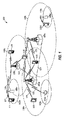
図1は、LTE-Aネットワークであり得る、通信のためのワイヤレスネットワーク100を示す。ワイヤレスネットワーク100は、いくつかの発展型ノードB(eNB)105と、他のネットワークエンティティとを含む。eNBは、UEと通信する局であってもよく、基地局、ノードB、アクセスポイントなどと呼ばれることもある。各eNB105は、特定の地理的エリアに通信カバレージを提供することができる。3GPPでは、「セル」という用語は、この用語が使用される文脈に応じて、カバレージエリアにサービスするeNBおよび/またはeNBサブシステムのこの特定の地理的カバレージエリアを指すことがある。
FIG. 1 shows a
eNBは、マクロセル、またはピコセルもしくはフェムトセルなどのスモールセル、および/または他のタイプのセルに通信カバレージを提供することができる。マクロセルは、一般に、比較的大きい地理的エリア(たとえば、半径数キロメートル)をカバーし、ネットワークプロバイダのサービスに加入しているUEによる無制限アクセスを可能にすることができる。ピコセルなどのスモールセルは、一般に、比較的小さい地理的エリアをカバーし、ネットワークプロバイダのサービスに加入しているUEによる無制限アクセスを可能にすることができる。フェムトセルなどのスモールセルも、一般に、比較的小さい地理的エリア(たとえば、自宅)をカバーし、無制限アクセスに加えて、フェムトセルとの関連付けを有するUE(たとえば、限定加入者グループ(CSG)内のUE、自宅内のユーザのためのUEなど)による制限付きアクセスも提供することができる。マクロセルのためのeNBは、マクロeNBと呼ばれることがある。スモールセルのためのeNBは、スモールセルeNB、ピコeNB、フェムトeNBまたはホームeNBと呼ばれることがある。図1に示す例では、eNB105a、105bおよび105cは、それぞれ、マクロセル110a、110bおよび110cのためのマクロeNBである。eNB105x、105y、および105zは、それぞれ、スモールセル110x、110y、および110zにサービスを提供するピコeNBまたはフェムトeNBを含み得る、スモールセルeNBである。eNBは、1つまたは複数(たとえば、2つ、3つ、4つなど)のセルをサポートし得る。
The eNB may provide communication coverage for a macro cell, or small cells such as pico cells or femto cells, and / or other types of cells. A macrocell can generally cover a relatively large geographic area (eg, a few kilometers in radius) and allow unrestricted access by UEs subscribing to the services of a network provider. Small cells, such as pico cells, can generally cover a relatively small geographic area and allow unrestricted access by UEs subscribing to the services of a network provider. Small cells, such as femtocells, also typically cover a relatively small geographic area (e.g., home) and, in addition to unrestricted access, have UEs associated with the femtocell (e.g., within a limited subscriber group (CSG)). UEs, UEs for home users, etc.). An eNB for a macro cell may be referred to as a macro eNB. An eNB for a small cell may be called a small cell eNB, a pico eNB, a femto eNB, or a home eNB. In the example shown in FIG. 1,
ワイヤレスネットワーク100は、同期動作または非同期動作をサポートし得る。同期動作の場合、eNBは、同様のフレームタイミングを有する場合があり、異なるeNBからの送信は、時間的にほぼ整合される場合がある。非同期動作の場合、eNBは、異なるフレームタイミングを有する場合があり、異なるeNBからの送信は、時間的に整合されない場合がある。
UE115は、ワイヤレスネットワーク100全体にわたって分散され、各UEは固定またはモバイルであり得る。UEは、端末、移動局、加入者ユニット、局などと呼ばれることもある。UEは、セルラーフォン、携帯情報端末(PDA)、ワイヤレスモデム、ワイヤレス通信デバイス、ハンドヘルドデバイス、タブレットコンピュータ、ラップトップコンピュータ、コードレスフォン、ワイヤレスローカルループ(WLL)局などであり得る。UEは、マクロeNB、ピコeNB、フェムトeNB、リレーなどと通信することが可能であり得る。図1では、稲妻(たとえば、通信リンク125)は、UEとサービングeNB(サービングeNBは、ダウンリンクおよび/またはアップリンク上でUEにサービスするように指定されたeNBである)との間の所望の送信、あるいはeNB間の所望の送信を示す。
LTE/LTE-Aは、ダウンリンク上で直交周波数分割多重(OFDM)を利用し、アップリンク上でシングルキャリア周波数分割多重(SC-FDM)を利用する。OFDMおよびSC-FDMは、システム帯域幅を、一般にトーン、ビンなどとも呼ばれる複数(K個)の直交サブキャリアに区分する。各サブキャリアは、データで変調され得る。一般に、変調シンボルは、OFDMでは周波数領域において送られ、SC-FDMでは時間領域において送られる。隣接するサブキャリア間の間隔は固定される場合があり、サブキャリアの総数(K)は、システム帯域幅に依存し得る。たとえば、Kは、1.4、3、5、10、15、または20メガヘルツ(MHz)の対応するシステム帯域幅に対して、それぞれ、72、180、300、600、900、および1200に等しくてもよい。システム帯域幅は、サブバンドに区分される場合もある。たとえば、サブバンドは1.08MHzをカバーすることができ、1.4、3、5、10、15、または20MHzの対応するシステム帯域幅に対して、それぞれ、1、2、4、8または16個のサブバンドが存在し得る。 LTE / LTE-A uses orthogonal frequency division multiplexing (OFDM) on the downlink and single carrier frequency division multiplexing (SC-FDM) on the uplink. OFDM and SC-FDM partition the system bandwidth into multiple (K) orthogonal subcarriers, also commonly referred to as tones, bins, and so on. Each subcarrier may be modulated with data. In general, modulation symbols are sent in the frequency domain with OFDM and in the time domain with SC-FDM. The spacing between adjacent subcarriers may be fixed, and the total number of subcarriers (K) may depend on the system bandwidth. For example, K may be equal to 72, 180, 300, 600, 900, and 1200, respectively, for corresponding system bandwidths of 1.4, 3, 5, 10, 15, or 20 megahertz (MHz). . The system bandwidth may be divided into sub-bands. For example, a sub-band may cover 1.08 MHz and 1, 2, 4, 8, or 16 sub-bands respectively for a corresponding system bandwidth of 1.4, 3, 5, 10, 15, or 20 MHz. Bands may be present.
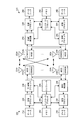
図2は、図1の基地局/eNBのうちの1つおよびUEのうちの1つであり得る、基地局/eNB105およびUE115の設計のブロック図を示す。制限付き関連付けシナリオの場合、eNB105は図1のスモールセルeNB105zであってもよく、UE115はUE115zであってもよく、UE115zは、スモールセルeNB105zにアクセスするために、スモールセルeNB105zに対するアクセス可能UEのリストに含まれることになろう。eNB105はまた、何らかの他のタイプの基地局であり得る。eNB105は、アンテナ234a〜234tを備えてもよく、UE115は、アンテナ252a〜252rを備えてもよい。
FIG. 2 shows a block diagram of a design of base station /
eNB105において、送信プロセッサ220は、データソース212からデータを受信し、コントローラ/プロセッサ240から制御情報を受信することができる。制御情報は、PBCH、PCFICH、PHICH、PDCCHなどについてのものであり得る。データは、PDSCHなどについてのものであり得る。送信プロセッサ220は、データおよび制御情報を処理(たとえば、符号化およびシンボルマッピング)して、それぞれ、データシンボルおよび制御シンボルを取得することができる。送信プロセッサ220はまた、たとえば、PSS、SSS、およびセル固有基準信号のための基準シンボルを生成することができる。送信(TX)多入力多出力(MIMO)プロセッサ230は、該当する場合、データシンボル、制御シンボル、および/または基準シンボルに対して空間処理(たとえば、プリコーディング)を実行することができ、出力シンボルストリームを変調器(MOD)232a〜232tを供給することができる。各変調器232は、(たとえば、OFDM用などに)それぞれの出力シンボルストリームを処理して、出力サンプルストリームを取得することができる。各変調器232は、出力サンプルストリームをさらに処理(たとえば、アナログに変換、増幅、フィルタリング、およびアップコンバート)して、ダウンリンク信号を取得することができる。変調器232a〜232tからのダウンリンク信号は、それぞれ、アンテナ234a〜234tを介して送信され得る。
In
UE115において、アンテナ252a〜252rは、eNB105からダウンリンク信号を受信することができ、受信信号を、それぞれ復調器(DEMOD)254a〜254rに供給することができる。各復調器254は、それぞれの受信信号を調整(たとえば、フィルタリング、増幅、ダウンコンバート、およびデジタル化)して、入力サンプルを取得することができる。各復調器254は、(たとえば、OFDM用などに)入力サンプルをさらに処理して、受信シンボルを取得することができる。MIMO検出器256は、復調器254a〜254rから受信シンボルを取得し、該当する場合は受信シンボルに対してMIMO検出を実行し、検出されたシンボルを供給することができる。受信プロセッサ258は、検出されたシンボルを処理(たとえば、復調、デインターリーブ、および復号)し、UE115のための復号されたデータをデータシンク260に供給し、復号された制御情報をコントローラ/プロセッサ280に供給することができる。
At
アップリンク上で、UE115において、送信プロセッサ264は、データソース262から(たとえば、PUSCH用の)データを受信および処理し、コントローラ/プロセッサ280から(たとえば、PUCCH用の)制御情報を受信および処理することができる。送信プロセッサ264はまた、基準信号のための基準シンボルを生成することができる。送信プロセッサ264からのシンボルは、該当する場合はTX MIMOプロセッサ266によってプリコーディングされ、(たとえば、SC-FDM用などに)変調器254a〜254rによってさらに処理され、eNB105に送信され得る。eNB105において、UE115からのアップリンク信号は、アンテナ234によって受信され、復調器232によって処理され、該当する場合はMIMO検出器236によって検出され、受信プロセッサ238によってさらに処理されて、UE115によって送られた復号されたデータおよび制御情報を取得することができる。受信プロセッサ238は、復号されたデータをデータシンク239に供給し、復号された制御情報をコントローラ/プロセッサ240に供給することができる。
On the uplink, at
コントローラ/プロセッサ240および280は、それぞれ、eNB105およびUE115における動作を指示することができる。eNB105におけるコントローラ/プロセッサ240および/もしくは他のプロセッサおよびモジュールならびに/またはUE115におけるコントローラ/プロセッサ280および/もしくは他のプロセッサならびにモジュールは、図3および図5に示す機能ブロックおよび/または本明細書で説明する技法のための他のプロセスを実行するか、またはそれらの実行を指示するためなどに、本明細書で説明する技法のための様々なプロセスを実行するか、またはそれらの実行を指示することができる。メモリ242および282は、それぞれ、eNB105およびUE115のためのデータおよびプログラムコードを記憶し得る。スケジューラ244は、ダウンリンクおよび/またはアップリンク上でのデータ送信のためにUEをスケジュールし得る。
Controllers /
本明細書の混合干渉管理技法による動作は、混合干渉情報に基づいて、ダウンリンクおよび/またはアップリンクのTDDサブフレームまたはスロットを動的に切り替えるためなどに、通信を管理することを行う。たとえば、本開示の態様によれば、eNBの論理は、ダウンリンクまたはアップリンクにおける追加のトラフィックを適応させるため、ダウンリンクまたはアップリンクのスループットを増加させるため、サービス品質(QoS)メトリックを満たすため、スペクトル、優先度、データクラス、デバイスクラス、サービスクラスなどを効率的に利用するためなどに、混合干渉に関する情報を分析して、ダウンリンクおよび/またはアップリンクのスケジューリングの切替えが実施されるべきかどうかを決定する。混合干渉に関する情報は、eNBによってサービスされる1つもしくは複数のUEによって報告される混合干渉情報、および/または、1つもしくは複数の他のeNB(たとえば、システム内の他のeNB、近隣eNB、eNBに対する望ましくないレベルの干渉を与える/経験することが可能なeNBなど)によって報告される混合干渉情報を含み得る。1つまたは複数の他のeNBによって報告される混合干渉情報は、その他のeNBのそれぞれの1つによってサービスされる1つまたは複数のUEに関する混合干渉情報(たとえば、UEによって、そのUEにサービスするその他のeNBのうちの1つに報告される混合干渉情報)を含み得る。したがって、本明細書の概念に従って動作するeNBは、ダウンリンクおよびアップリンクのスケジューリング変更が実施される前のその変更の影響を分析し、そのような分析に基づいて、許容できない混合干渉をもたらすことなしに、ダウンリンクスロットおよび/またはアップリンクスロットの動的な切替えを実施することができる。 Operations in accordance with the mixed interference management techniques herein provide for managing communications, such as to dynamically switch downlink and / or uplink TDD subframes or slots based on mixed interference information. For example, according to aspects of the present disclosure, the eNB logic may adapt to additional traffic on the downlink or uplink, increase downlink or uplink throughput, meet quality of service (QoS) metrics. Information on mixed interference should be analyzed and switching of downlink and / or uplink scheduling performed, such as to make efficient use of spectrum, priority, data class, device class, service class, etc. Determine whether or not. Information on mixed interference is mixed interference information reported by one or more UEs served by the eNB, and / or one or more other eNBs (e.g., other eNBs in the system, neighboring eNBs, mixed interference information reported by an eNB capable of giving / experiencing an undesirable level of interference to the eNB. Mixed interference information reported by one or more other eNBs may include mixed interference information for one or more UEs served by each one of the other eNBs (e.g., by the UE, serving the UE). Mixed interference information reported to one of the other eNBs). Thus, an eNB operating in accordance with the concepts herein may analyze the impact of downlink and uplink scheduling changes before those changes are implemented and, based on such analysis, result in unacceptable mixed interference. Without, dynamic switching of downlink slots and / or uplink slots can be implemented.
図3は、本明細書の概念による混合干渉管理のためのジャミンググラフの生成および/または再生成を行う動作の高レベルフロー図を示す。具体的には、フロー300は、混合干渉情報およびそこからのジャミンググラフを提供する際に、eNB105におけるコントローラ/プロセッサ240および/もしくはスケジューラ244ならびに/またはUE115におけるコントローラ/プロセッサ280によって実行され得るような機能を示す。
FIG. 3 illustrates a high-level flow diagram of operations for generating and / or regenerating jamming graphs for mixed interference management in accordance with the concepts herein. Specifically, flow 300 may be performed by controller /
図示したフロー300のブロック301において、ネットワーク要素(たとえば、図1のeNB105および/またはUE115のうちの1つまたは複数)が混合干渉測定を行う。たとえば、本開示の一態様に従って動作する基地局(たとえば、eNB105)は、アップリンクサブフレームからダウンリンクサブフレームへの切替えが有益であるか、またはダウンリンクサブフレームからアップリンクサブフレームへの切替えが有益であるかどうかを決定するために、様々なネットワーク要素の間の混合干渉プロファイルについての情報を利用し得る。本明細書の態様によれば、eNBは、ダウンリンクおよび/またはアップリンクのスケジューリングの切替えが有益であるかを決定する際に、基地局間の干渉電力(たとえば、隣接する基地局送信からの受信電力がUEからの所望のアップリンク信号よりもはるかに強い場合があり、基地局受信機における受信デセンスをもたらす、ダウンリンクからアップリンクへの干渉)ならびにUE間の干渉電力(たとえば、異なるサービングセルを有する2つのセルエッジUEが任意に互いに近い場合があり、それにより、基地局ジャミングが、その2つのUEにおけるダウンリンク/アップリンクの不一致から生じる、アップリンクからダウンリンクへの干渉)を利用し得る。したがって、通信システム内で動作する基地局およびUEは、混合干渉測定を実行して、上記に関連するデータを収集し得る。たとえば、eNB105の論理(たとえば、コントローラ/プロセッサ240によって実行される論理)および/またはUE115の論理(たとえば、コントローラ/プロセッサ280によって実行される論理)は、本明細書で説明するように、混合干渉測定を実行するための機能を実装し得る。
At
本開示の態様による動作において、基地局間の混合干渉は、他の基地局から各基地局によって測定され得る。同様に、UE間の混合干渉は、他のUEから各UEによって測定され得る。そのような混合干渉測定は、様々な技法を使用して、本明細書の概念に従って行われ得る。たとえば、混合干渉測定プロトコルは、通信フレーム構造内に実装される場合があり、それにより、特定のサブフレーム(本明細書では混合干渉測定サブフレームと呼ばれる)が、混合干渉測定において使用するための基準信号の送信に利用される。 In operation according to aspects of the present disclosure, mixed interference between base stations may be measured by each base station from other base stations. Similarly, mixed interference between UEs may be measured by each UE from other UEs. Such mixed interferometry may be performed according to the concepts herein using various techniques. For example, a mixed interference measurement protocol may be implemented within a communication frame structure, whereby a particular subframe (referred to herein as a mixed interference measurement subframe) may be used for use in mixed interference measurement. Used for transmitting reference signals.
混合干渉について、UEと通信している基地局を備えるネットワーク環境に関して上記で説明したが、本明細書の概念は、様々なネットワークタイプおよび通信構成に適用可能であることを諒解されたい。混合干渉が可能であるTDD通信を実装する任意の送信機/受信機構成に関する実施形態が実装され得る。たとえば、本明細書の概念による混合干渉管理のための混合干渉測定およびジャミンググラフは、ピアツーピア通信、デバイス間通信、メッシュネットワーク通信などに関して提供され得る。一例として、実施形態の混合干渉管理は、第5世代(5G)モバイルネットワーク構成において実装されるマシンタイプ通信(MTC)に関して提供され得る。上記に従って、混合干渉管理が提供される通信中のデバイスは、上述の基地局およびUEと従来は考えられていたデバイス構成に加えてまたはその代替として、インターネットアプライアンス、測定プローブ、車両、スマートデバイス(たとえば、モノのインターネット(IoT)デバイス)、ドローンなどの、デバイス構成を含み得る。 Although mixed interference has been described above with reference to a network environment comprising a base station in communication with the UE, it should be appreciated that the concepts herein are applicable to various network types and communication configurations. Embodiments may be implemented for any transmitter / receiver configuration that implements TDD communication where mixed interference is possible. For example, mixed interference measurements and jamming graphs for mixed interference management according to the concepts herein may be provided for peer-to-peer communication, device-to-device communication, mesh network communication, and so on. As an example, the mixed interference management of the embodiments may be provided for machine type communication (MTC) implemented in a fifth generation (5G) mobile network configuration. In accordance with the above, the communicating devices for which mixed interference management is provided may include Internet appliances, measurement probes, vehicles, smart devices (in addition to or instead of the above-described device configurations conventionally considered base stations and UEs). For example, it may include device configurations such as Internet of Things (IoT) devices, drones, and the like.
上記のいくつかの実装形態によれば、基地局の何らかのサブセット(たとえば、基地局のランダムまたは擬似ランダムなサブセット、サブセットの一部ではないその他の基地局を有する通信システム全体にわたってほぼ均等に分散されているものとして選択された基地局のサブセット、サブセットの一部ではないその他の基地局とインターリーブされた基地局のサブセットなど)は、第1の基地局混合干渉測定サブフレームの間にパイロット信号を送信することができ、基地局の別のサブセット(たとえば、パイロット送信サブセットの一部ではないその他の基地局、またはその何らかの部分)は、基地局のパイロット送信サブセットから受信された信号を測定するかまたはさもなければ監視することができる。同様に、基地局の別のサブセット(たとえば、パイロット送信サブセットの一部ではないその他の基地局、またはその何らかの部分)は、第2の基地局混合干渉測定サブフレームの間にパイロット信号を送信することができ、基地局のさらなるサブセット(たとえば、第1の基地局混合干渉測定サブフレームの間にパイロット信号を送信した基地局、もしくはその何らかの部分、および/または通信システム内で動作する残りの基地局の一部もしくは全部など)は、基地局のパイロット送信サブセットから受信された信号を測定するかまたはさもなければ監視することができる。したがって、混合干渉測定サブフレームにおけるパイロット信号の送信および監視の反復は、いくつかのサブフレームを含むことができ、通信システム内のすべての基地局は、混合干渉測定パイロットの送信と、その他の基地局による混合干渉測定パイロット送信を受信することの監視の両方を行う。パイロット信号の送信および監視の反復においてパイロットが送信される混合干渉サブフレームは、隣接しない場合がある(たとえば、1つまたは複数のトラフィックサブフレームは、すべての基地局による送信および監視の反復の混合干渉サブフレーム間に配設され得る)ことを諒解されたい。 According to some implementations described above, some subset of base stations (e.g., a random or pseudo-random subset of base stations, distributed approximately evenly throughout a communication system having other base stations that are not part of the subset) (E.g., a subset of base stations that are selected as having a subset, a subset of base stations interleaved with other base stations that are not part of the subset, etc.) Whether another subset of the base stations (e.g., other base stations that are not part of the pilot transmission subset, or some portion thereof) can measure signals received from the base station's pilot transmission subset. Or else it can be monitored. Similarly, another subset of base stations (e.g., other base stations that are not part of the pilot transmission subset, or some part thereof) transmit pilot signals during the second base station mixed interference measurement subframe. A further subset of base stations (e.g., the base station that transmitted the pilot signal during the first base station mixed interference measurement subframe, or some portion thereof, and / or the remaining base operating within the communication system) Some or all of the stations) may measure or otherwise monitor signals received from the pilot transmission subset of the base station. Therefore, the repetition of transmission and monitoring of pilot signals in the mixed interference measurement subframe may include several subframes, and all base stations in the communication system transmit the mixed interference measurement pilot and the other base stations. It both monitors the reception of the mixed interference measurement pilot transmission by the station. Mixed interference subframes in which pilots are transmitted in pilot signal transmission and monitoring iterations may not be contiguous (e.g., one or more traffic subframes may have mixed transmission and monitoring iterations by all base stations). (Can be placed between interfering subframes).
同様に、UEの何らかのサブセット(たとえば、UEのランダムまたは擬似ランダムなサブセット、通信システム全体にわたってほぼ均等に分散されたセルにおいて動作するUEのサブセット(通信システムの他のセルは、サブセットの一部ではない、その中で動作するUEを有する)、サブセットの一部ではない、その中で動作するUEを有する通信システムのその他のセルとインターリーブされたセルにおいて動作するUEのサブセットなど)は、第1のUE混合干渉測定サブフレームの間にサウンディング基準信号(SRS)を送信することができ、UEの別のサブセット(たとえば、SRS送信サブセットの一部ではないその他のUE、またはその何らかの部分)は、UEのSRS送信サブセットから受信された信号を測定するかまたはさもなければ監視することができる。同様に、UEの別のサブセット(たとえば、SRS送信サブセットの一部ではないその他のUE、またはその何らかの部分)は、第2のUE混合干渉測定サブフレームの間にSRSを送信することができ、UEのさらなるサブセット(たとえば、第1のUE混合干渉測定サブフレームの間にSRSを送信したUE、もしくはその何らかの部分、および/または通信システム内で動作する残りのUEの一部もしくは全部など)は、UEのSRS送信サブセットから受信された信号を測定するかまたはさもなければ監視することができる。したがって、混合干渉測定サブフレームにおけるSRSの送信および監視の反復は、いくつかのサブフレームを含むことができ、通信システム内のすべてのUEは、混合干渉測定SRSの送信と、その他のUEによる混合干渉測定SRS送信を受信することの監視の両方を行う。SRS信号の送信および監視の反復においてSRSが送信される混合干渉サブフレームは、隣接しない場合がある(たとえば、1つまたは複数のトラフィックサブフレームは、すべてのUEによる送信および監視の反復の混合干渉サブフレーム間に配設され得る)ことを諒解されたい。 Similarly, some subset of UEs (e.g., a random or pseudo-random subset of UEs, a subset of UEs operating in cells that are approximately evenly distributed throughout the communication system (other cells of the communication system may be Not having a UE operating therein), not being part of a subset, such as a subset of UEs operating in cells interleaved with other cells of the communication system having UEs operating therein) is the first Can transmit a sounding reference signal (SRS) during the UE mixed interference measurement subframe of another subset of UEs (e.g., other UEs that are not part of the SRS transmission subset, or any part thereof), The signal received from the UE's SRS transmission subset may be measured or otherwise monitored. Similarly, another subset of UEs (e.g., other UEs that are not part of the SRS transmission subset, or some part thereof) can transmit the SRS during the second UE mixed interference measurement subframe, A further subset of UEs (e.g., the UE that transmitted the SRS during the first UE mixed interference measurement subframe, or some portion thereof, and / or some or all of the remaining UEs operating in the communication system, etc.) , May be measured or otherwise monitored from the SRS transmission subset of the UE. Thus, the repetition of transmission and monitoring of the SRS in the mixed interference measurement subframe may include several subframes, and all UEs in the communication system may transmit the mixed interference measurement SRS and mix with other UEs. It both monitors the reception of interference measurement SRS transmissions. The mixed interference subframes in which the SRS is transmitted in the SRS signal transmission and monitoring iterations may not be contiguous (e.g., one or more traffic subframes may have mixed transmission and monitoring iterations by all UEs). (Can be disposed between subframes).
上記の例は、混合干渉測定プロトコルの使用について説明しており、それにより、混合干渉測定サブフレームは、混合干渉測定において使用するための基準信号の送信に利用されるが、本明細書の概念に従って動作可能な実装形態は、混合干渉測定を実行するための追加または代替の技法を利用し得る。たとえば、様々なネットワーク要素は、通常ならば混合干渉測定に適応しない通信プロトコルに従って行われる送信の間に、他のネットワーク要素から受信された信号を監視するように動作し得る(たとえば、基地局は、他の基地局から受信された様々な信号を監視することができ、UEは、他のUEから受信された様々な信号を監視することができる、など)。一例として、監視側ネットワーク要素は、通信プロトコルに従って信号を送信することができるが、監視側ネットワーク要素における通信負荷は、代わりに監視が実施され得るようなものである期間の間に(たとえば、性能またはサービス品質に悪影響を及ぼすかまたは容認できないほどの影響を及ぼすことなしに送信が遅延され得るアイドル送信サブフレームの間に、など)、ネットワーク要素は、その他のネットワーク要素のうちの適切なネットワーク要素から受信された信号を測定するかまたはさもなければ監視するように動作し得る。 The above example describes the use of a mixed interference measurement protocol, whereby the mixed interference measurement subframe is utilized for transmitting a reference signal for use in mixed interference measurement, although the concept herein is not May operate utilizing additional or alternative techniques for performing mixed interference measurements. For example, various network elements may operate to monitor signals received from other network elements during transmissions that are normally made according to communication protocols that do not accommodate mixed interference measurements (e.g., a base station may , Can monitor various signals received from other base stations, the UE can monitor various signals received from other UEs, and so on). As an example, the monitoring network element may send signals according to the communication protocol, but the communication load on the monitoring network element may be changed during a period in which monitoring may be performed instead (e.g., performance Or during idle transmission subframes where transmission can be delayed without adversely or unacceptably affecting service quality, etc.), the network element is a suitable one of the other network elements May be operable to measure or otherwise monitor the signal received from.
フロー300のブロック301において実行される混合干渉測定は、本開示の態様による様々な時間に実行され得る。たとえば、混合干渉測定は、通信システム内で動作する基地局および/またはUEによって、混合干渉測定プロトコルのタイミングに従って、時間スケジュール(たとえば、GPSタイミング信号、通信システムクロックなど)に基づいてなど、周期的に行われ得る。例示的な実装形態による動作において、混合干渉測定は、特定の数のサブフレームの反復ごとに行われ得る(たとえば、X個のダウンリンクサブフレームおよび/またはY個のアップリンクサブフレームごと、XおよびYは、たとえば、2から50に及ぶ数のサブフレームであってもよく、XおよびYは、同じであってもよく同じでなくてもよい)。追加または代替として、混合干渉測定は、1つまたは複数のイベントの発生時に行われ得る。例示的な実装形態によれば、混合干渉測定の1つまたは複数の反復は、セル内で移動する1つまたは複数のUEなど、通信システム内で生じる重要な変更イベント(たとえば、他のセル内のUEに対する干渉を潜在的に変えるのに十分な距離、他のセル内のUEに対する干渉を潜在的に変えるセルエッジのより近くにまたはセルエッジからさらに離れてUEが配設されることになる移動、実施されているダウンリンクおよび/またはアップリンクのスケジューリングの切替えなど)によってトリガされ得る。混合干渉測定は、追加または代替として、通信トラフィックが低減された期間、または通信システム動作に望ましくない影響を及ぼすことなしに混合干渉測定が適応され得る他の期間の間など、ランダムにまたは擬似ランダムに行われ得る。
The mixed interference measurement performed in
上記の混合干渉測定のいずれかまたはすべては、すべてのネットワークノードまたはその何らかの部分による混合干渉測定を提供し得る。たとえば、基地局混合干渉測定が開始された場合、基地局混合干渉測定の完全な反復(すなわち、通信システムにおいて動作するすべての基地局が混合干渉測定を行う)が生じ得る。同様に、UE混合干渉測定が開始された場合、UE混合干渉測定の完全な反復(すなわち、通信システムにおいて動作するすべてのUEが混合干渉測定を行う)が生じ得る。代替的に、基地局混合干渉測定および/またはUE混合干渉測定の部分的な反復が生じ得る(たとえば、第1のサブセットの基地局/UEが1つの反復において混合干渉測定を行うが、第2のサブセットの基地局/UEが後続の反復において混合干渉測定を行う)。別の例では、基地局混合干渉測定および/またはUE混合干渉測定の複数の反復が生じ得る(たとえば、通信システムにおいて動作するすべての基地局/UEが1つの反復において複数の混合干渉測定を行う)。 Any or all of the above mixed interference measurements may provide mixed interference measurements by all network nodes or some part thereof. For example, if a base station mixed interference measurement is initiated, a complete repetition of the base station mixed interference measurement (ie, all base stations operating in the communication system perform the mixed interference measurement) may occur. Similarly, if a UE mixed interference measurement is initiated, a complete repetition of the UE mixed interference measurement (ie, all UEs operating in the communication system perform the mixed interference measurement) may occur. Alternatively, partial repetition of base station mixed interference measurements and / or UE mixed interference measurements may occur (e.g., a first subset of base stations / UEs perform mixed interference measurements in one repetition, Of subsets of base stations / UEs perform mixed interference measurements in subsequent iterations). In another example, multiple iterations of base station mixed interference measurements and / or UE mixed interference measurements may occur (e.g., all base stations / UEs operating in a communication system perform multiple mixed interference measurements in one iteration) ).
前述のように、通信システム内の混合干渉環境に関する情報は、本明細書の概念による混合干渉管理を提供するために使用され得る。したがって、図示したフロー300のブロック302において、ネットワーク要素が混合干渉測定情報を報告する。たとえば、eNB105の論理(たとえば、コントローラ/プロセッサ240によって実行される論理)および/またはUE115の論理(たとえば、コントローラ/プロセッサ280によって実行される論理)は、本明細書で説明するように、混合干渉情報の報告を実行するための機能を実装し得る。混合干渉情報の報告は、オーバージエアシグナリングを介しておよび/またはバックホール接続を介して行われる場合があり、報告される混合干渉情報は直接、測定された干渉電力レベルであってもよく、またはそこから導出された情報であってもよい。
As mentioned above, information about the mixed interference environment in the communication system may be used to provide mixed interference management according to the concepts herein. Accordingly, at
本明細書の例の動作において、各UEは混合干渉測定情報をそのサービング基地局に報告し、混合干渉情報は、ブロック301における動作による他のUEの監視によって提供されるか、または他のUEの監視から他の方法で導出される情報(たとえば、UE間の干渉)を含む。同様に、基地局は混合干渉測定情報を交換し、混合干渉情報は、ブロック301における動作による他の基地局の監視によって提供されるか、または他の基地局の監視から他の方法で導出される情報(たとえば、基地局間の干渉)を含む。さらに、本開示の態様による、基地局によって交換される混合干渉情報は、他のUEを監視するその基地局によってサービスされるUEによって提供されるか、またはそれらのUEから他の方法で導出される情報(たとえば、UE間の干渉)を含む。任意のそのようなネットワーク要素によって報告される混合情報は、本明細書の概念による混合干渉管理の態様を実行する際に使用され得るような、そのネットワーク要素についての混合干渉プロファイルを提供する。
In the operation of the example herein, each UE reports mixed interference measurement information to its serving base station, and the mixed interference information is provided by monitoring other UEs by the operation in
基地局による混合干渉情報の交換は、通信システムのすべての基地局が、その混合干渉情報(たとえば、報告側基地局によって測定された混合干渉情報、ならびに、その基地局によってサービスされるUEによって、その基地局に報告される混合干渉情報)を通信システムのすべての他の基地局に報告することを含み得る。代替的に、基地局による混合干渉情報の交換は、基地局が、通信システムの基地局のサブセットに報告することを含み得る。たとえば、基地局は、報告側基地局および/または報告側基地局によってサービスされるUEのうちの1つもしくは複数によって測定される混合干渉、またはその何らかのしきい値量に関連付けられた他の基地局のみに、混合干渉情報を報告してもよい。基地局のそのようなサブセットへの混合干渉情報の報告は、基地局間のデータ通信を低減するかまたは最小限に抑えるうえで有利であり得る。たとえば、混合干渉情報の報告は、トラフィックチャネルを搬送する際にも利用される無線周波数スペクトルを使用してなど、ワイヤレスリンクを介して行われ得る。したがって、そのような報告についての基地局間のデータ通信を最小限に抑えることは、通信ネットワークにおけるトラフィック搬送能力に及ぼす影響を減らすために望ましい場合がある。追加または代替として、基地局間の混合干渉情報を報告するためにバックホールリンク(たとえば、ワイヤライン接続、光ファイバ接続、帯域外ワイヤレス接続など)が利用され得る。いくつかの例示的な実装形態による動作において、そのようなバックホールリンクは、所望される場合、よりロバストな混合干渉情報を搬送するために利用され得る。 The exchange of mixed interference information by the base stations is based on the fact that all base stations of the communication system have their mixed interference information (e.g., mixed interference information measured by the reporting base station, as well as the UE served by the base station, Reporting mixed interference information reported to that base station) to all other base stations of the communication system. Alternatively, the exchange of mixed interference information by the base station may include the base station reporting to a subset of the base stations of the communication system. For example, the base station may be a reporting base station and / or other bases associated with mixed interference measured by one or more of the UEs served by the reporting base station, or some threshold amount thereof. Mixed interference information may be reported only to stations. Reporting mixed interference information to such a subset of base stations may be advantageous in reducing or minimizing data communication between base stations. For example, reporting of mixed interference information may be over a wireless link, such as using a radio frequency spectrum that is also utilized in carrying traffic channels. Therefore, minimizing data communication between base stations for such reporting may be desirable to reduce its impact on traffic carrying capacity in a communication network. Additionally or alternatively, backhaul links (eg, wireline connections, fiber optic connections, out-of-band wireless connections, etc.) may be utilized to report mixed interference information between base stations. In operation according to some example implementations, such a backhaul link may be utilized to carry more robust mixed interference information if desired.
報告される特定の混合干渉情報は、基地局間のおよび/またはUEと基地局との間のデータ通信を低減するかまたはさもなければ最小限に抑えるように、同様に選択されるか、または他の方法で構成され得る。たとえば、場合によっては他の関連のあるまたはさもなければ有益な情報(たとえば、測定が行われたロケーション、測定が行われた時間など)を伴う、信号強度情報および信号源識別情報(たとえば、基地局識別情報またはUE識別情報などの送信局識別子)を含み得るような、UEおよび/または基地局によって行われる測定は、混合干渉情報報告において提供され得る。追加または代替として、UEおよび/または基地局によって行われた測定から導出された情報は、混合干渉情報報告において提供され得る。たとえば、そのような導出された情報は、干渉局から受信された信号がしきい値(たとえば、混合干渉許容しきい値)を超えるかどうか、測定された干渉が報告側受信機にとっては許容できないことを示す情報、報告側受信機が許容できる干渉のために必要とされる信号電力バックオフの量に関する情報、ロケーションおよび/または方向情報(たとえば、基地局の受信アンテナ方向から計算されたUEの相対ロケーション、受信信号強度、タイミングオフセットなど)などを含み得る。そのような導出された情報は、単独であるいはUEおよび/または基地局によって行われた上述の測定と組み合わせて報告され得る。たとえば、上記の導出された情報のうちの1つまたは複数は、基地局間のおよび/またはUEと基地局との間のデータ通信を低減するかまたはさもなければ最小限に抑えるために、行われた対応する測定を含めることなしに、報告され得る。 The particular mixed interference information reported is also selected to reduce or otherwise minimize data communication between base stations and / or between UE and base station, or It can be configured in other ways. For example, signal strength information and source identification information (e.g., a base station), possibly with other relevant or otherwise useful information (e.g., location where measurements were taken, time when measurements were taken, etc.) Measurements made by the UE and / or the base station, which may include a station identity or a transmitting station identifier such as UE identity, may be provided in the mixed interference information report. Additionally or alternatively, information derived from measurements made by the UE and / or the base station may be provided in a mixed interference information report. For example, such derived information may indicate whether the signal received from the interfering station exceeds a threshold (e.g., a mixed interference tolerance threshold), the measured interference is unacceptable to the reporting receiver Information indicating the amount of signal power back-off required for interference that the reporting receiver can tolerate, location and / or directional information (e.g., the UE's calculated from the base station's receive antenna direction). Relative location, received signal strength, timing offset, etc.). Such derived information may be reported alone or in combination with the above measurements made by the UE and / or the base station. For example, one or more of the above derived information may be used to reduce or otherwise minimize data communication between base stations and / or between UEs and base stations. Can be reported without including the corresponding measurements taken.
上記で説明したように、本明細書の概念による実装形態は、混合干渉情報を導出する際にしきい値を利用し得る。そのようなしきい値は、様々な異なるしきい値メトリックおよび/または大きさを含み得る。たとえば、混合干渉許容しきい値は、特定の通信システムの動作において受信局が許容できると見なされる、(たとえば、干渉オーバーサーマル(IoT)によって測定された)干渉の所定の大きさを含み得る。そのようなしきい値を使用して、報告側ネットワーク要素は、報告側ネットワーク要素による測定値がしきい値を超える、送信局ごとの混合干渉情報を含む報告を提供するように動作し得る。報告は、測定値、しきい値を超えた量、しきい値を超えたことを示す情報、しきい値を超えないために必要とされる送信電力バックオフの大きさ、ロケーションもしくは相対ロケーションに関する情報および/または混合干渉のインスタンスを回避するためにビームフォーミング、ヌルステアリング、もしくは指向性ビーム選択において使用するための報告側ネットワーク要素のチャネルフェード推定値、ならびに/あるいは上記で説明した他の情報を含み得る。 As explained above, implementations according to the concepts herein may utilize thresholds in deriving mixed interference information. Such thresholds may include a variety of different threshold metrics and / or magnitudes. For example, the mixed interference tolerance threshold may include a predetermined amount of interference (e.g., measured by interference overthermal (IoT)) that is considered acceptable by a receiving station in the operation of a particular communication system. Using such a threshold, the reporting network element may operate to provide a report including mixed interference information for each transmitting station for which a measurement by the reporting network element exceeds the threshold. The report may relate to the measurement, the amount that has exceeded the threshold, information indicating that the threshold has been exceeded, the magnitude of the transmit power backoff required to not exceed the threshold, the location or relative location. Information and / or channel fading estimates of the reporting network element for use in beamforming, null steering, or directional beam selection to avoid instances of mixed interference, and / or other information described above. May be included.
やはり上記で説明したように、本明細書の概念による実装形態は、許容できないまたはさもなければ望ましくない混合干渉を回避するために、送信電力バックオフのレベルに関する情報を利用し得る。そのようなバックオフ情報は、しきい値の大きさを超えた量(たとえば、特定の送信ネットワーク要素から受信された信号によって上記の混合干渉許容しきい値を超えた量)から計算され得る。追加または代替として、特定の結果を達成するために、そのようなバックオフ情報が決定され得る。たとえば、アップリンクからダウンリンクへの干渉シナリオでは、報告側UEまたはUEが報告する先の基地局は、場合によっては2つのUEにおけるダウンリンク/アップリンクの不一致から生じる基地局ジャミングを回避するのに十分なバックオフを計算し得る。ダウンリンクからアップリンクへの干渉シナリオでは、報告側基地局は、場合によっては基地局受信機において生じる受信デセンスを回避するのに十分なバックオフを計算し得る。 As also explained above, implementations according to the concepts herein may utilize information regarding the level of transmit power back-off to avoid unacceptable or otherwise undesirable mixed interference. Such back-off information may be calculated from an amount that exceeds a threshold magnitude (eg, an amount that exceeds the mixed interference tolerance threshold described above due to a signal received from a particular transmitting network element). Additionally or alternatively, such backoff information may be determined to achieve a particular result. For example, in an uplink to downlink interference scenario, the reporting UE or the base station to which the UE reports may avoid base station jamming that may result from a downlink / uplink mismatch between the two UEs. To calculate a sufficient backoff. In a downlink-to-uplink interference scenario, the reporting base station may calculate a sufficient backoff to avoid reception desense that may occur at the base station receiver.
本開示の態様による実装形態では、基地局は、測定された混合干渉情報(たとえば、UE間の混合干渉測定値)を一定の測定イベントの発生に基づいて報告するように、そのUEを構成および/または制御することができる。実施形態は、様々なデバイス間の(たとえば、基地局から1つもしくは複数のUEおよび/または1つもしくは複数の他の基地局への)シグナリングを提供して、混合干渉情報を測定するように、ならびに/あるいは、基地局および/またはUEによって検出され得るような1つまたは複数の特定のイベントに応答してまたはそれらのイベントに関連して、測定された混合干渉情報を報告するように、そのようなデバイスを構成することができる。追加または代替として、実施形態は、基地局またはUEによって検出され得るような1つまたは複数の特定のイベントに応答してまたはそれらに関連して、混合干渉情報の報告を制御するために、様々なデバイス間のシグナリングを提供し得る。たとえば、特定のUEからの干渉の重要な変更は、報告をトリガし得る。UEによる、その測定された混合干渉の報告は、ハンドオーバおよび再選択などのモビリティ関連イベントの発生に基づいてトリガされる場合もある。そのようなモビリティ関連の報告は、ペアにおける各UEが異なるセルにあり、ハンドオーバイベントによって潜在的に著しく変化する(たとえば、そのようなペアのセットの変更をもたらす)か、またはさもなければ混合干渉環境に対するかなりの変更をもたらす、UEのペアについてのUE間の干渉を踏まえると、有利であり得る。本開示の態様による実装形態では、基地局は、基地局によって測定され、UEによって報告される混合干渉情報を、他の基地局と交換することもできる。この混合干渉情報の交換は、たとえば、構成された測定イベントおよび/またはモビリティ関連イベントに基づいてトリガされ得る。 In an implementation according to aspects of the disclosure, the base station configures and configures the UE to report measured mixed interference information (e.g., mixed interference measurements between UEs) based on the occurrence of certain measurement events. / Or can be controlled. Embodiments provide signaling between various devices (e.g., from a base station to one or more UEs and / or one or more other base stations) to measure mixed interference information. And / or report the measured mixed interference information in response to or in connection with one or more specific events as may be detected by the base station and / or the UE, Such a device can be configured. Additionally or alternatively, embodiments may be implemented to control the reporting of mixed interference information in response to or in association with one or more specific events as may be detected by a base station or UE. Signaling between different devices. For example, a significant change in interference from a particular UE may trigger a report. The UE's report of its measured mixed interference may be triggered based on the occurrence of mobility related events such as handover and reselection. Such mobility-related reports may indicate that each UE in the pair is in a different cell and potentially significantly changed by a handover event (e.g., resulting in a change in the set of such pairs) or otherwise mixed interference It may be advantageous in view of the interference between UEs for a pair of UEs that results in significant changes to the environment. In an implementation according to aspects of the disclosure, the base station may also exchange mixed interference information measured by the base station and reported by the UE with other base stations. This exchange of mixed interference information may be triggered, for example, based on configured measurement events and / or mobility related events.
したがって、フロー300の図示の例は、ブロック302における混合干渉情報の報告のインスタンスが後に続く、ブロック301における混合干渉の測定のインスタンスを示しているが、本明細書の概念による混合干渉の測定および報告は、様々なスケジューリングに従うものであり得る(たとえば、測定および報告は、同じスケジュールおよび/または異なるスケジュールに従い得る)ことを諒解されたい。たとえば、混合干渉測定は、測定スケジュールに従って(たとえば、周期的に、1つまたは複数のイベントの発生時に、ランダムまたは擬似ランダムな時間に、など)様々なネットワーク要素によって行われる場合があるが、混合干渉情報報告は、報告スケジュールに従って(たとえば、周期的に、1つまたは複数のイベントの発生時に、ランダムまたは擬似ランダムな時間に、など)様々なネットワーク要素によって実行される場合があり、測定スケジュールおよび報告スケジュールは、協調的であってもよく、無関係であってもよい。したがって、本明細書の概念に従って実施される測定および報告は、互いに対して非同期的に、またはさもなければ異なるスケジュールに従って実行され得る。測定スケジュールおよび報告スケジュールが開始のために同じメトリック(たとえば、時間、イベントなど)を利用する場合でも、利用されるメトリックの特定の値は異なる場合があり、それにより、測定および報告が非同期的に実行されることになることを諒解されたい。
Thus, while the illustrated example of the
上述の非同期の測定および報告の結果として、ネットワーク要素による報告の間に複数の測定が行われたか、または場合によっては、ネットワーク要素による報告の間に新しい測定が行われなかった可能性がある。本明細書のいくつかの例によれば、ネットワーク要素は、次の報告インスタンスにおいて、すべての適切な測定値(および/またはそこから導出された情報)を報告するように動作し得る。代替的に、ネットワーク要素は、次の報告インスタンスにおいて、直近の測定値(および/またはそこから導出された情報)のみを報告するように動作し得る。報告の最後のインスタンス以降にネットワーク要素が新しい測定を行わなかった場合、ネットワーク要素は、次の報告インスタンスにおいて、以前の測定値(および/またはそこから導出された情報)を再報告し得る。代替的に、報告の最後のインスタンス以降に新しい測定を行わなかったネットワーク要素は、ネットワーク要素間のデータ通信を低減するかまたはさもなければ最小限に抑えるためなどに、次の報告インスタンスにおいて、報告を提供しないように動作し得る。 As a result of the asynchronous measurement and reporting described above, multiple measurements may have been taken during reporting by the network element, or in some cases, no new measurements may have been taken during reporting by the network element. According to some examples herein, the network element may operate to report all appropriate measurements (and / or information derived therefrom) in the next reporting instance. Alternatively, the network element may operate in the next reporting instance to report only the most recent measurements (and / or information derived therefrom). If the network element has not made a new measurement since the last instance of the report, the network element may re-report previous measurements (and / or information derived therefrom) in the next report instance. Alternatively, network elements that have not made new measurements since the last instance of the report are reported in the next report instance, such as to reduce or otherwise minimize data communication between network elements. May not operate.
前述のように、通信システム内の混合干渉環境に関する情報は、本明細書の概念による混合干渉管理を提供するために使用され得る。たとえば、通信システム内の他のネットワーク要素の混合干渉プロファイルに関する情報は、本明細書の概念による混合干渉管理の態様において利用されるジャミンググラフを構築するために基地局によって利用され得る。したがって、図示したフロー300のブロック303において、基地局に報告される混合情報(たとえば、基地局によってサービスされるUEによって提供される混合干渉情報と、他の基地局によって提供される混合干渉情報とを含む)は、ジャミンググラフを生成(または以前に生成されたジャミンググラフを更新)するために使用される。たとえば、eNB105の論理(たとえば、コントローラ/プロセッサ240によって実行される論理)および/またはUE115の論理(たとえば、コントローラ/プロセッサ280によって実行される論理)は、本明細書で説明するように、混合干渉測定情報を使用してジャミンググラフを生成および/または更新するための機能を実装し得る。
As mentioned above, information about the mixed interference environment in the communication system may be used to provide mixed interference management according to the concepts herein. For example, information regarding mixed interference profiles of other network elements in the communication system may be utilized by the base station to construct a jamming graph utilized in aspects of mixed interference management according to the concepts herein. Thus, at
本明細書の概念に従って提供される例示的なジャミンググラフは、混合干渉シナリオ(すなわち、いくつかのセルがアップリンクにおいて動作し、それと同時に他のセルがダウンリンクにおいて動作する)をもたらす可能性があるスケジューリング決定の影響を評価するために使用され得る情報を含んでいる。したがって、報告された混合干渉測定情報に基づいて、本開示の態様に従って動作する基地局は、その基地局の動作に関連する混合干渉プロファイルを集約するジャミンググラフを生成することができる。ダウンリンクからアップリンクへの混合干渉およびアップリンクからダウンリンクへの混合干渉は、本開示の一態様に従って提供される1つまたは複数のジャミンググラフ(たとえば、基地局間ジャミンググラフおよび/またはUE間ジャミンググラフ)の形で集約され得る。 An exemplary jamming graph provided in accordance with the concepts herein may result in mixed interference scenarios (i.e., some cells operate in the uplink while other cells operate in the downlink). Contains information that can be used to assess the impact of certain scheduling decisions. Thus, based on the reported mixed interference measurement information, a base station operating in accordance with aspects of the present disclosure can generate a jamming graph that aggregates mixed interference profiles related to the operation of the base station. Mixed interference from the downlink to the uplink and mixed interference from the uplink to the downlink may include one or more jamming graphs provided according to one aspect of the present disclosure (e.g., between base station jamming graphs and / or between UEs). Jamming graph).
ダウンリンクからアップリンクへの混合干渉管理の決定に関して利用され得るような、例示的な基地局間ジャミンググラフでは、基地局ごとにまたは関連する基地局(たとえば、ジャミンググラフを生成する基地局またはジャミンググラフが生成される基地局に対して、許容できないまたは望ましくない干渉をもたらす可能性がある、または干渉をもたらすことが可能であるような、通信システムに配設された基地局)ごとに1つの頂点(Vertex)が与えられる。たとえば、ある基地局(たとえば、BSi)から送信された信号が別の基地局(たとえば、BSj)に対する許容できないまたは望ましくない干渉をもたらすジャミンググラフにおいて、ある基地局は別の基地局に接続され得る。混合干渉許容しきい値(たとえば、許容できるIoTしきい値(BS_TOLERABLE_IOT))が使用される例示的な実装形態では、BSjにおいてBSiについて測定された最大(Max_IoT)が混合干渉許容しきい値よりも大きい(たとえば、BSjにおけるBSiについてのMax_IoT>BSjのBS_TOLERABLE_IOT)場合、BSiはBSjに接続される。そのような接続は、接続された基地局間で非同期のダウンリンクおよびアップリンクのスケジューリングが実施される通信に対して望ましくないまたは許容できない干渉を行うのに十分な、ダウンリンクからアップリンクへの混合干渉のインスタンスを表す。基地局間のこれらの接続(本明細書ではエッジとも呼ばれる)は、基地局間ジャミンググラフにおいて基地局間の線またはリンクとして表され得る。基地局間ジャミンググラフにおいて表される接続またはエッジは、それらに関連付けられたラベルを有することができ、ラベルは、接続に関する情報(たとえば、受信基地局によって測定された、測定された混合干渉電力レベル、混合干渉を回避するためのバックオフ電力レベルなど)を提供する。たとえば、本開示のいくつかの態様に従って実装される基地局間ジャミンググラフにおいて提供されるエッジのラベルは、BSiに起因するBSjにおけるIoTがBSjのBS_TOLERABLE_IOTに等しく(またはそれ未満に)なることを保証するために、BSiにおいて必要とされる送信電力(たとえば、TX電力/EIRP)バックオフを含む。 In an exemplary inter-base station jamming graph, such as may be utilized for a downlink to uplink mixed interference management decision, per base station or an associated base station (e.g., a base station or jamming graph that generates the jamming graph) One for each base station installed in the communication system that may or may cause unacceptable or undesirable interference to the base station from which the graph is generated. Vertex is given. For example, in a jamming graph where a signal transmitted from one base station (e.g., BS i ) causes unacceptable or undesirable interference to another base station (e.g., BS j ), one base station connects to another base station. Can be done. In an exemplary implementation where a mixed interference tolerance threshold (e.g., an acceptable IoT threshold (BS_TOLERABLE_IOT)) is used, the maximum (Max_IoT) measured for BS i at BS j is the mixed interference tolerance threshold greater than (e.g., BS_TOLERABLE_IOT of Max_IoT> BS j for BS i in BS j) if, BS i is connected to the BS j. Such a connection may have enough downlink-to-uplink to cause undesired or unacceptable interference with communications where asynchronous downlink and uplink scheduling is performed between the connected base stations. Represents an instance of mixed interference. These connections between base stations (also referred to herein as edges) may be represented as lines or links between base stations in an inter-base station jamming graph. Connections or edges represented in the inter-base station jamming graph can have a label associated with them, where the label contains information about the connection (e.g., the measured mixed interference power level measured by the receiving base station). , Back-off power levels to avoid mixed interference). For example, the label edges are provided in some base stations among jamming graph is implemented in accordance with aspects of the present disclosure, IoT at BS j due to BS i is equal (or less) to BS_TOLERABLE_IOT the BS j to ensure that the transmit power required in BS i (e.g., TX power / EIRP) includes a back-off.
アップリンクからダウンリンクへの混合干渉管理の決定に関して利用され得るような、例示的なUE間ジャミンググラフでは、UEごとにまたは関連するUE(たとえば、ジャミンググラフを生成する基地局によってサービスされるUEまたはジャミンググラフが生成されるUEに対して、許容できないまたは望ましくない干渉をもたらす可能性がある、または干渉をもたらすことが可能であるような、通信システムに配設されたUE)ごとに1つの頂点が与えられる。たとえば、あるUE(たとえば、UEi)から送信された信号が別のUE(たとえば、UEj)に対する許容できないまたは望ましくない干渉をもたらすジャミンググラフにおいて、あるUEは別のUEに接続され得る。混合干渉許容しきい値(たとえば、許容できるIoTしきい値(UE_TOLERABLE_IOT))が使用される例示的な実装形態では、UEjにおいてUEiについて測定された最大(Max_IoT)が混合干渉許容しきい値よりも大きい(たとえば、UEjにおけるUEiについてのMax_IoT>UEjのUE_TOLERABLE_IOT)場合、UEiはUEjに接続される。そのような接続は、接続されたUE間で非同期のアップリンクおよびダウンリンクのスケジューリングが実施される通信に対して望ましくないまたは許容できない干渉を行うのに十分な、アップリンクからダウンリンクへの混合干渉のインスタンスを表す。上記で説明した基地局間ジャミンググラフと同様に、UE間のこれらの接続(本明細書ではエッジとも呼ばれる)は、UE間ジャミンググラフにおいてUE間の線またはリンクとして表され得る。UE間ジャミンググラフにおいて表される接続またはエッジも、それらに関連付けられたラベルを有することができ、ラベルは、接続に関する情報(たとえば、受信UEによって測定された、測定された混合干渉電力レベル、混合干渉を回避するためのバックオフ電力レベルなど)を提供する。たとえば、本開示のいくつかの態様に従って実装されるUE間ジャミンググラフにおいて提供されるエッジのラベルは、UEiに起因するUEjにおけるIoTがUEjのUE_TOLERABLE_IOTに等しく(またはそれ未満に)なることを保証するために、UEiにおいて必要とされる送信電力(たとえば、TX電力/EIRP)バックオフを含む。 In an exemplary inter-UE jamming graph, such as may be utilized for uplink-to-downlink mixed interference management decisions, per UE or an associated UE (e.g., a UE served by a base station that generates the jamming graph) One for each UE installed in the communication system, which may cause unacceptable or undesired interference, or can cause interference for the UE for which the jamming graph is generated) Vertices are given. For example, one UE may be connected to another UE in a jamming graph in which a signal transmitted from one UE (eg, UE i ) causes unacceptable or undesirable interference to another UE (eg, UE j ). In an example implementation where a mixed interference tolerance threshold (e.g., an acceptable IoT threshold (UE_TOLERABLE_IOT)) is used, the maximum (Max_IoT) measured for UE i at UE j is the mixed interference tolerance threshold greater than (e.g., Max_IoT> UE_TOLERABLE_IOT the UE j for UE i in UE j) if, UE i is connected to the UE j. Such a connection may have sufficient uplink-to-downlink mixing to cause undesirable or unacceptable interference with the communication in which asynchronous uplink and downlink scheduling is performed between the connected UEs. Represents an instance of interference. Similar to the inter-base station jamming graph described above, these connections between UEs (also referred to herein as edges) may be represented as lines or links between UEs in the inter-UE jamming graph. Connections or edges represented in the inter-UE jamming graph may also have a label associated with them, the label providing information about the connection (e.g., measured mixed interference power level measured by the receiving UE, mixed Back-off power levels to avoid interference). For example, the label edges are provided in the UE between jamming graph is implemented in accordance with aspects of the present disclosure is equal (or less) to UE_TOLERABLE_IOT the IoT is UE j in UE j due to UE i becomes possible , The required transmit power (eg, TX power / EIRP) back-off at UE i .
上記で説明したように、基地局および/またはUEによって報告される混合干渉情報は直接、測定された干渉電力レベルであってもよく、またはそこから導出された情報であってもよい。本開示の態様によれば、混合干渉測定から導出されたそのような混合干渉情報は、測定された混合干渉電力レベルに基づいて生成され得るようなジャミンググラフにおけるエッジの存在の指示を含み得る。そのようなエッジ情報の報告は、本明細書で説明するように、ジャミンググラフの生成を容易にしながら、混合干渉情報の低減されたまたはさもなければ効率的な通信を行うために使用され得る。 As explained above, the mixed interference information reported by the base station and / or the UE may be directly the measured interference power level, or may be information derived therefrom. According to aspects of the present disclosure, such mixed interference information derived from the mixed interference measurement may include an indication of the presence of an edge in the jamming graph as may be generated based on the measured mixed interference power level. Such reporting of edge information may be used to facilitate reduced jamming or otherwise efficient communication of mixed interference information, as described herein, while facilitating the generation of jamming graphs.
例示的な実装形態の動作において提供され得るような、例示的なジャミンググラフは、図4Aおよび図4Bに示されている。図4Aの例は、上記で説明したフロー300に従って提供される混合干渉情報から生成され得るような、基地局間ジャミンググラフ410としての基地局間ジャミンググラフのグローバルビューを示す。基地局間ジャミンググラフ410の図示の例では、頂点401〜407は通信システムの基地局を表す。通信に対して望ましくないまたは許容できない干渉を行うのに十分な、アップリンクからダウンリンクへの混合干渉のインスタンスを表す上述のエッジは、頂点のうちの特定の頂点を接続する線によって示されている。混合干渉を回避するためのdB単位のバックオフ電力レベルを表す上述のラベルは、図示のエッジの各々に関連付けられた数字によって示されている。たとえば、図示の例のラベルは、干渉対熱雑音の3dB許容限界を満たすのに必要とされる電力バックオフを示す。
Exemplary jamming graphs, such as may be provided in operation of an exemplary implementation, are shown in FIGS. 4A and 4B. The example of FIG. 4A shows a global view of the inter-base station jamming graph as inter-base
いくつかの実装形態では、各基地局は、その基地局に直接接続されたエッジについての情報のみについて学習し、その情報を使用することができる。したがって、そのような基地局によって生成された(またはそのような基地局についてジャミンググラフが生成された)基地局間ジャミンググラフは、その基地局に直接接続されたエッジのみを含む場合がある。しかしながら、別の実装形態では、基地局は、場合によってはネイバーのみに制限された、他の基地局間のエッジについて学習することもできる。したがって、そのような基地局によって生成された基地局間ジャミンググラフは、ジャミンググラフを生成した基地局(またはその基地局についてジャミンググラフが生成された)を含まない基地局ペアを接続するエッジを含み得る。一例として、このことは、ネイバー基地局が方向を変換できるかどうかを基地局が予測することを可能にすることができ、この情報を干渉環境のそれ自体の分析に組み込むことができる。 In some implementations, each base station can learn and use only information about edges directly connected to that base station. Thus, an inter-base station jamming graph generated by such a base station (or for which a jamming graph was generated for such a base station) may include only edges directly connected to the base station. However, in another implementation, a base station may learn about edges between other base stations, possibly restricted to neighbors only. Thus, the inter-base station jamming graph generated by such a base station includes edges connecting base station pairs that do not include the base station that generated the jamming graph (or for which the jamming graph was generated). obtain. As an example, this can allow the base station to predict if a neighbor base station can change direction and can incorporate this information into its own analysis of the interference environment.
図4Bの例は、6dBの送信電力バックオフを用いて、図4Aの基地局間ジャミンググラフ410を生成する際に利用された混合干渉情報から再生成された基地局間ジャミンググラフ420を示す。図4Bに示す例でわかるように、この6dBの電力バックオフにより、エッジのうちのいくつか(たとえば、頂点401と頂点403との間、頂点405と頂点406との間、および頂点406と頂点407との間のエッジ)が消去され、それにより、電力バックオフが、それらの頂点によって表される基地局間の望ましくないまたは許容できないアップリンクからダウンリンクへの混合干渉を回避するのに十分であることを示す。図4Bの基地局間ジャミンググラフ420に示すラベルは、残りのエッジに関して干渉対熱雑音の3dBの許容限界を満たすのに必要とされるさらなる電力バックオフを示すために、同様に更新されることを諒解されたい。
The example of FIG. 4B shows an inter-base
基地局間ジャミンググラフ実装形態を参照しながら、図4Aおよび図4Bに示す例示的なジャミンググラフについて上記で説明したが、UE間ジャミンググラフ実装形態は、示されているジャミンググラフと質的に同様であり得る。しかしながら、UE間ジャミンググラフの実装形態における頂点はUEを表しており、したがって、ジャミンググラフ内のUEのロケーションは、UE表現に対応することになる。同様に、エッジおよびラベルは、UEのダウンリンクからアップリンクへの混合干渉情報のエッジおよびラベルに対応することになる。いくつかの実装形態のUE間ジャミンググラフは加えて、対応するUEの頂点のラベルとして含まれ得るものなど、各UEがどのセルに属するかに関する情報を含み得る。 While the example jamming graph shown in FIGS.4A and 4B has been described above with reference to an inter-base station jamming graph implementation, the inter-UE jamming graph implementation is qualitatively similar to the jamming graph shown. Can be However, the vertices in the inter-UE jamming graph implementation represent the UE, and thus the location of the UE in the jamming graph will correspond to the UE representation. Similarly, the edges and labels will correspond to the edges and labels of the UE's downlink to uplink mixed interference information. The inter-UE jamming graph of some implementations may additionally include information about which cell each UE belongs to, such as what may be included as a vertex label of the corresponding UE.
上記のことから諒解され得るように、本明細書の概念に従って提供されるジャミンググラフは、ダウンリンクまたはアップリンクにおける追加のトラフィックを適応させるため、ダウンリンクまたはアップリンクのスループットを増加させるため、サービス品質(QoS)メトリックを満たすため、スペクトルを効率的に利用するためなどに、ダウンリンクおよび/またはアップリンクのスケジューリングの切替えが実施されるべきかどうかを決定するために利用され得る。したがって、上記によるジャミンググラフは、混合干渉による影響を最小限に抑えるためなどに、本明細書の実装形態によるスケジューリング決定に組み込まれる。一例として、本明細書の概念に従って動作するeNB105のスケジューラ244は、ダウンリンクおよびアップリンクのスケジューリング変更が実施される前のその変更の影響を分析し、そのような分析に基づいて、許容できない混合干渉をもたらすことなしに、ダウンリンクスロットおよび/またはアップリンクスロットの動的な切替えを実施することができる。ダウンリンクスロットおよび/またはアップリンクスロットの動的な切替えのそのような分析および実装は、電力バックオフを用いたジャミンググラフの再生成などによって、電力バックオフを分析および/または実装することを含み得る。
As can be appreciated from the above, a jamming graph provided in accordance with the concepts herein provides a service to accommodate additional traffic on the downlink or uplink, to increase downlink or uplink throughput, It may be used to determine whether a downlink and / or uplink scheduling switch should be performed, such as to meet quality (QoS) metrics, to efficiently utilize spectrum, etc. Therefore, the jamming graph according to the above is incorporated into the scheduling decisions according to the implementations herein, such as to minimize the effects of mixed interference. By way of example, the
たとえば、本明細書の概念によるジャミンググラフを使用して、各基地局は、アップリンク送信対ダウンリンク送信をスケジュールすることのコストおよび利益を評価することができる。いくつかの実装形態によれば、1つまたは複数のジャミンググラフの干渉プロファイルは、混合干渉を考慮に入れるスケジューラメトリック(たとえば、比例公平スケジューラメトリック)を計算するために使用される場合があり、アップリンク送信対ダウンリンク送信の決定は、(たとえば、どちらの決定がスケジューラメトリックのより高い値を与えるかを比較することによって)スケジューラメトリックに基づき得る。たとえば、ダウンリンクおよびアップリンクのうちの一方向のみにおいてスケジュールされるのを待っているトラフィックがある場合、スケジューラは、その方向を日和見的に選択することができる。別の例として、予定された受信機が強い干渉物によって妨害される場合、その方向の選択はスケジューラによって回避される。比例公平スケジューラメトリックについて上記で説明したが、スケジューラは、特定の実装形態に応じて、様々な異なるスケジューラメトリックを使用し得ることを諒解されたい。 For example, using a jamming graph according to the concepts herein, each base station can evaluate the costs and benefits of scheduling uplink versus downlink transmissions. According to some implementations, the interference profile of one or more jamming graphs may be used to calculate a scheduler metric (e.g., a proportional fair scheduler metric) that takes into account mixed interference, and The link transmission versus downlink transmission decision may be based on the scheduler metric (eg, by comparing which decision gives a higher value of the scheduler metric). For example, if there is traffic waiting to be scheduled in only one of the downlink and uplink, the scheduler may opportunistically select that direction. As another example, if the intended receiver is obstructed by strong interferers, its direction selection is avoided by the scheduler. While the proportional fair scheduler metric has been described above, it should be appreciated that the scheduler may use a variety of different scheduler metrics, depending on the particular implementation.
図5は、本明細書の概念による混合干渉管理のための動作の高レベルフロー図を示す。具体的には、フロー500は、混合干渉管理動作を提供する際に、eNB105におけるコントローラ/プロセッサ240および/もしくはスケジューラ244ならびに/またはUE115におけるコントローラ/プロセッサ280によって実行され得るような機能を示す。
FIG. 5 illustrates a high-level flow diagram of operations for mixed interference management in accordance with the concepts herein. Specifically,
図示したフロー500のブロック501において、アップリンクサブフレームをダウンリンクサブフレームに切り替えることまたはダウンリンクサブフレームをアップリンクサブフレームに切り替えることが許可されるかどうか(たとえば、ネットワーク構成は、方向を切り替えることができないことを示す場合がある)、また、望ましいかどうか(たとえば、ダウンリンクおよびアップリンクのうちの一方向のみにおいてスケジュールされるのを待っているトラフィック、ダウンリンクまたはアップリンクの一方は高需要であるが、他方のリンクは低需要である、など)についての決定が行われる。現時点ではアップリンクサブフレームまたはダウンリンクサブフレームを切り替えることが許可されず、望ましくないと決定された場合、図示の例による処理は、後続の時間における決定のためにブロック501に戻る。しかしながら、現時点ではアップリンクサブフレームまたはダウンリンクサブフレームを切り替えることが許可され、望まれると決定された場合、図示の例による処理は、アップリンクサブフレームをダウンリンクサブフレームに切り替えることまたはダウンリンクサブフレームをアップリンクサブフレームに切り替えることが有益であるかどうか(たとえば、許容できないまたは望ましくない混合干渉が生じることになるかどうか)を決定する動作のためのブロック502に進む。
At
アップリンクサブフレームまたはダウンリンクサブフレームの切替えが実行されるべきかを決定するために、図示の例のブロック502において1つまたは複数のジャミンググラフが分析される。たとえば、本開示の態様によれば、各基地局は、異なる混合干渉軽減方式を比較することができる。あるセルにおける送信が反対方向における近隣セルの送信に対して許容できないまたはさもなければ望ましくない混合干渉を引き起こすと特定されたか、またはその逆のことが特定された場合、スケジューラは、たとえば、そのような送信を回避し、(たとえば、ダウンリンクの場合は基地局において適用される、またはアップリンクの場合はUEにシグナリングされる)適切な送信電力バックオフとともにそのような送信を進め、(たとえば、ダウンリンクの場合は基地局において適用される、またはアップリンクの場合はUEにシグナリングされる)送信ビームフォーミングの適切な変更とともにそのような送信を進めることを選ぶことができる。そのような方式を評価するために、スケジューラは、行われるべき変更(たとえば、送信電力バックオフ、送信ビームフォーミングなど)を考慮してジャミンググラフを再生成し、得られたジャミンググラフを分析することに進むことができる。
One or more jamming graphs are analyzed at
上記によれば、フロー500の図示の例は、ブロック502において、推定的なアップリンクサブフレームまたはダウンリンクサブフレームの切替えに関連付けられたエッジについての関連するジャミンググラフを分析するように動作する。したがって、図示の例のブロック503において、推定的なアップリンクサブフレームまたはダウンリンクサブフレームの切替えに関連するエッジがジャミンググラフにおいて見つかったかどうかについての決定が行われる。たとえば、推定的なアップリンクからダウンリンクへの切替えでは、基地局間ジャミンググラフは、ネイバー基地局において現在の基地局によって引き起こされる干渉について助言するが、UE間ジャミンググラフは、現在スケジュールされているUEに対してネイバーUEによって引き起こされる干渉について助言する。同様に、推定的なダウンリンクからアップリンクへの切替えでは、UE間ジャミンググラフは、ネイバーUEに対して現在スケジュールされているUEによって引き起こされる干渉について助言するが、基地局間ジャミンググラフは、現在の基地局に対してネイバー基地局によって引き起こされる干渉について助言する。したがって、基地局間ジャミンググラフは、推定的切替えが行われるべき基地局に対してエッジ(たとえば、その基地局を通信システム内の他の基地局と接続する1つまたは複数のエッジ)が存在するかを決定するために分析され、したがって、切替えから生じる潜在的な許容できないまたは望ましくない混合干渉を示す場合があり、UE間ジャミンググラフは、推定的切替えが行われるべき基地局によってサービスされるUEに対してエッジ(たとえば、それらのUEのいずれかを通信システム内の他の基地局によってサービスされるUEと接続する1つまたは複数のエッジ)が存在するかを決定するために分析され、したがって、切替えから生じる潜在的な許容できないまたは望ましくない混合干渉を示す場合がある。
In accordance with the above, the illustrated example of
推定的切替えのためのエッジがジャミンググラフに存在せず、したがって、許容できないまたは望ましくない混合干渉が生じる可能性がないとブロック503において決定された場合、フロー500の図示の例による処理はブロック504に進む。ブロック504において、アップリンクサブフレームまたはダウンリンクサブフレームの切替えがスケジューラによって実施され、それにより、混合干渉管理は、許容できないまたはさもなければ望ましくない混合干渉は生じないとの決定の後に切替えを実施するように制御することによって提供されており、処理は、アップリンクサブフレームまたはダウンリンクサブフレームの切替えが望まれるかどうかの後続の決定のためにブロック501に戻る。
If the edge for the putative switch is not present in the jamming graph, and thus it is determined in
しかしながら、推定的切替えのための1つまたは複数のエッジがジャミンググラフに存在し、したがって、許容できないまたは望ましくない混合干渉が生じる可能性があるとブロック503において決定された場合、フロー500の図示の例による処理はブロック505に進む。ブロック505において、1つまたは複数の干渉軽減方式を使用して、ジャミンググラフが再生成される。たとえば、1つまたは複数のジャミンググラフは、送信バックオフを用いて再生成される場合があり、送信バックオフは、推定的切替えが行われるべき通信であるが混合干渉の減少をもたらす通信にサービスするのに十分な送信電力レベルを提供するために決定され得る。
However, if one or more edges for the putative switch are present in the jamming graph, and thus it is determined at
いくつかの実装形態による動作において、たとえば、混合干渉軽減方式は、他の基地局に対する混合干渉の影響を低減するために、電力調整(たとえば、1つもしくは複数のネットワーク要素における送信電力バックオフおよび/または1つもしくは複数のネットワーク要素における送信電力増加)を適用する基地局を提供することができる。たとえば、混合干渉の影響が(たとえば、ネイバーセルから現在のセルへの)着信方向にある場合、いくつかの実装形態は、サブフレーム方向切替えに適応するために、現在のセルにおける送信電力増加を提供することができる。しかしながら、混合干渉の影響が(たとえば、現在のセルからネイバーセルへの)発信方向にある場合、いくつかの実装形態は、サブフレーム方向切替えに適応するために、現在のセルにおける送信電力バックオフを提供することができる。一例として、現在のセルがダウンリンクからアップリンクに変換しており、近隣基地局からの受信信号レベルが高すぎる場合、現在のセルのUEは、干渉を克服するために、その送信電力をブーストするように制御され得る。追加または代替として、現在のセルがダウンリンクからアップリンクに変換している場合、混合干渉軽減方式は、他のUEに及ぼす混合干渉の影響を低減するために、送信電力バックオフを適用するUEを提供することができる(たとえば、送信電力バックオフ値は、MAX_BACKOFF_UEの限界までの、すべての発信エッジを除去するのに必要とされる最高値であり得る)。そのような混合干渉軽減方式の一例によれば、電力調整は、少なくとも1つの発信エッジを除去する場合にのみ適用され得る。別の例として、現在のセルがアップリンクからダウンリンクに変換しており、ネイバーセルにおけるUEによって受信される現在の基地局信号が高すぎる場合、ネイバー基地局は、干渉を克服するために、その送信電力をブーストするように制御され得る。追加または代替として、現在のセルがアップリンクからダウンリンクに変換している場合、混合干渉軽減方式は、他の基地局に及ぼす混合干渉の影響を低減するために、送信電力バックオフを適用する現在の基地局を提供することができる(たとえば、送信電力バックオフ値は、MAX_BACKOFF_BSの限界までの、すべての発信エッジを除去するのに必要とされる最高値であり得る)。基地局(たとえば、ス
ケジューラ244の論理)は、各ネットワーク要素によって適用されるバックオフを計算することができ、非集中的にジャミンググラフを再生成する(たとえば、新規のよりスパースなジャミンググラフを計算する)ことができる。
In operation according to some implementations, for example, mixed interference mitigation schemes may be used to reduce the effects of mixed interference on other base stations (e.g., transmit power back-off and And / or base stations that apply transmit power increase in one or more network elements). For example, if the effect of mixed interference is in the incoming direction (e.g., from a neighbor cell to the current cell), some implementations may increase the transmit power in the current cell to accommodate subframe direction switching. Can be provided. However, if the effects of mixed interference are in the outgoing direction (e.g., from the current cell to a neighbor cell), some implementations may consider transmitting power backoff in the current cell to accommodate subframe direction switching. Can be provided. As an example, if the current cell is converting from downlink to uplink and the received signal level from a neighboring base station is too high, the UE in the current cell may boost its transmit power to overcome interference To be controlled. Additionally or alternatively, if the current cell is converting from the downlink to the uplink, the mixed interference mitigation scheme may be applied to a UE that applies transmit power back-off to reduce the effect of mixed interference on other UEs. (E.g., the transmit power backoff value may be the highest value needed to remove all outgoing edges, up to the limit of MAX_BACKOFF_UE). According to one example of such a mixed interference mitigation scheme, power adjustment may be applied only when removing at least one outgoing edge. As another example, if the current cell is converting from the uplink to the downlink and the current base station signal received by the UE in the neighbor cell is too high, the neighbor base station can It can be controlled to boost its transmit power. Additionally or alternatively, if the current cell is converting from uplink to downlink, the mixed interference mitigation scheme applies transmit power backoff to reduce the effects of mixed interference on other base stations The current base station can be provided (eg, the transmit power backoff value can be the highest value needed to remove all outgoing edges, up to the limit of MAX_BACKOFF_BS). The base station (e.g., the logic of scheduler 244) can calculate the backoff applied by each network element and regenerate the jamming graph decentralized (e.g., calculate a new, more sparse jamming graph). can do.
混合干渉軽減方式を踏まえて、アップリンクサブフレームまたはダウンリンクサブフレームの切替えが実行されるべきかを決定するために、図示の例のブロック506において1つまたは複数の再生成されたジャミンググラフが分析される。再生成されたジャミンググラフに反映された、1つまたは複数の軽減方式の適用にもかかわらず、あるセルにおける送信が反対方向における近隣セルの送信に対して許容できないまたはさもなければ望ましくない混合干渉を引き起こすと特定されたか、またはその逆のことが特定された場合、スケジューラは、そのような送信を回避することを選ぶことができる。したがって、図示の例のブロック507において、推定的なアップリンクサブフレームまたはダウンリンクサブフレームの切替えに関連するエッジが再生成されたジャミンググラフにおいて見つかったかどうかについての決定が行われる。たとえば、アップリンクサブフレームの切替えが代わりにダウンリンクサブフレームをもたらす場合、再生成された基地局間ジャミンググラフおよびUE間ジャミンググラフは、推定的切替えのためのエッジが存在し、したがって、干渉軽減を伴う場合でも切替えから生じる潜在的な許容できないまたは望ましくない混合干渉を示すかどうかを決定するために分析される場合がある。同様に、ダウンリンクサブフレームの切替えが代わりにアップリンクサブフレームをもたらす場合、再生成された基地局間ジャミンググラフおよびUE間ジャミンググラフは、推定的切替えのためのエッジが存在するかを決定するために分析され、したがって、干渉軽減を伴う場合でも切替えから生じる潜在的な許容できないまたは望ましくない混合干渉を示す場合がある。
Given the mixed interference mitigation scheme, one or more regenerated jamming graphs in
推定的切替えのための1つまたは複数のエッジが再生成されたジャミンググラフに存在し、したがって、許容できないまたは望ましくない混合干渉が生じる可能性があるとブロック507において決定された場合、フロー500の図示の例による処理はブロック508に進む。ブロック508において、スケジューラは、推定的なアップリンクまたはダウンリンクの切替えを実施せず、代わりに、アップリンクサブフレームまたはダウンリンクサブフレームの切替えが望まれるかどうかの後続の決定のためにブロック501に戻る。それでも、本明細書の実装形態による動作において、アップリンクサブフレームまたはダウンリンクサブフレームの切替えを行うかまたはさもなければその切替えに適応することを試みるためにアクションが取られる場合がある。たとえば、基地局は、アップリンクまたはダウンリンクの切替えを実施するかまたは容易にするための動作変更(たとえば、送信電力バックオフ、ビームフォーミング調整、アップリンクサブフレームまたはダウンリンクサブフレームの切替えなど)を制御または要求するために、1つまたは複数のネットワーク要素と通信することができる。
If one or more edges for the putative switch are present in the regenerated jamming graph, and thus are determined in
しかしながら、推定的切替えのためのエッジが再生成されたジャミンググラフに存在せず、したがって、許容できないまたは望ましくない混合干渉が生じる可能性がないとブロック507において決定された場合、フロー500の図示の例による処理はブロック504に進む。たとえば、ブロック504において、ジャミンググラフを再生成する際に使用された1つまたは複数の干渉軽減方式と組み合わせたアップリンクサブフレームまたはダウンリンクサブフレームの切替えがスケジューラによって実施される場合があり、それにより、混合干渉管理は、許容できないまたはさもなければ望ましくない混合干渉は生じないとの決定の後に、対応する混合干渉軽減方式とともに切替えを実施するように制御することによって提供されている。いくつかの実装形態によれば、フロー500のブロック504において実行される動作は、上記に加えてまたはその代替として分析を含み得る。たとえば、スケジューラの論理は、混合干渉環境に鑑みて可能であると決定されたが、望ましくないまたは有利ではない場合がある切替えを実施するかどうかを決定し得る。例示的な実装形態では、そのような分析は、干渉を軽減するために電力バックオフを適用した後、得られたスループットが非常に遅い場合があるので、切替えが所望の結果をもたらさない場合があり、したがって、スケジューラは切替えを実施しないと決定する場合があることを明らかにすることができる。図示の例のブロック504における処理の後、処理は、アップリンクサブフレームまたはダウンリンクサブフレームの切替えが望まれるかどうかの後続の決定のためにブロック501に戻る。
However, if the edge for the putative switch is not present in the regenerated jamming graph, and thus it is determined in
ブロック504においてアップリンクサブフレームまたはダウンリンクサブフレームの切替えを実施することは、サブフレーム切替えおよび関連する混合干渉軽減方式に加えて、動作を含み得ることを諒解されたい。たとえば、様々な動作、機能、通信などが、相応に実施され得る。送信電力バックオフが実施される場合、たとえば、電力バックオフを補償するために、変調コーディング方式(MCS)および/または他の通信属性が制御/変更され得る。
It should be appreciated that implementing uplink or downlink subframe switching in
上記で説明した例示的な実装形態から、本明細書の概念による動作は、スケジューラ(たとえば、eNB105のスケジューラ244)が混合干渉プロファイルに気づき、それにより、ジャミンググラフを計算することを可能にすることが容易にわかる。このことは、今度は、名目上のダウンリンクサブフレームの方向をアップリンクに変換するまたはその逆を行うという決定の影響を評価するために使用され得る。したがって、基地局は、アップリンク方向およびダウンリンク方向から選択し、混合干渉測定報告に基づいて送信ビームフォーミングおよび/または送信電力を調整することによって、混合干渉の影響を制限することが可能になる。
From the example implementations described above, operation in accordance with the concepts herein allows a scheduler (e.g.,
上記の概念は、いくつかの通信システムおよびネットワーク要素の構成に対して適用可能である。たとえば、説明する例示的な実装形態は、単入力単出力(SISO)構成、単入力多出力(SIMO)構成、多入力単出力(MISO)構成、および/または多入力多出力(MIMO)構成を有するネットワーク要素に対して利用され得る。MIMOビームフォーミングでは、部分的には、送信ビームフォーミングにより、送信機がその信号の指向性を制御することが可能になる、受信機ヌリングにより、受信機が干渉よりもその所望の信号を重視することが可能になる、および/または3Dアンテナアレイ構成により、角度分離の増大によるさらなる干渉除去が可能になるので、アップリンク-ダウンリンク混合干渉は、あまり影響を及ぼさない可能性がある。それにもかかわらず、MIMO構成のジャミンググラフの使用は、SISO構成のジャミンググラフの使用と同様である。しかしながら、MIMO構成に関して検討すべき2〜3の改良点としては、ジャミングの影響を低減するために、混合干渉を念頭に置いてビームフォーミング方向が選択され得る(たとえば、ビーム選択は、信号対漏れ比を最大化する方法で実行され得る)こと、電力バックオフを決定するために、最良のビーム方向から生じるIoTが許容IoTと比較されるべきであること、IoT計算はMIMOビームフォーミング、受信機ヌリングおよび角度分離の増大を考慮すべきであることが含まれる。 The above concept is applicable to some communication systems and configurations of network elements. For example, the described exemplary implementations include a single-input single-output (SISO) configuration, a single-input multiple-output (SIMO) configuration, a multiple-input single-output (MISO) configuration, and / or a multiple-input multiple-output (MIMO) configuration. Can be used for network elements that have In MIMO beamforming, in part, transmit beamforming allows the transmitter to control the directivity of its signal.Receiver nulling causes the receiver to emphasize its desired signal over interference And / or the 3D antenna array configuration allows for additional interference cancellation due to increased angular separation, so uplink-downlink mixed interference may have less impact. Nevertheless, the use of a jamming graph in a MIMO configuration is similar to the use of a jamming graph in a SISO configuration. However, a few improvements to consider for a MIMO configuration include that the beamforming direction can be selected with mixed interference in mind to reduce the effects of jamming (e.g., beam selection is signal-to-leakage Can be performed in a manner that maximizes the ratio), that the IoT resulting from the best beam direction should be compared to the allowed IoT to determine the power backoff, the IoT calculation is MIMO beamforming, receiver Includes that increased nulling and angular separation should be considered.
情報および信号が様々な異なる技術および技法のいずれかを使用して表され得ることを、当業者は理解されよう。たとえば、上記の説明全体にわたって参照され得るデータ、命令、コマンド、情報、信号、ビット、シンボル、およびチップは、電圧、電流、電磁波、磁場もしくは磁性粒子、光場もしくは光学粒子、またはそれらの任意の組合せによって表され得る。 Those of skill in the art would understand that information and signals may be represented using any of a variety of different technologies and techniques. For example, data, instructions, commands, information, signals, bits, symbols, and chips that may be referred to throughout the above description may include voltages, currents, electromagnetic waves, magnetic or magnetic particles, light or optical particles, or any of them. It can be represented by a combination.
図3および図5の機能ブロックおよびモジュールは、プロセッサ、電子デバイス、ハードウェアデバイス、電子構成要素、論理回路、メモリ、ソフトウェアコード、ファームウェアコードなど、またはそれらの任意の組合せを備え得る。 The functional blocks and modules of FIGS. 3 and 5 may comprise processors, electronic devices, hardware devices, electronic components, logical circuits, memories, software codes, firmware codes, etc., or any combination thereof.
本明細書の本開示に関して説明する様々な例示的な論理ブロック、モジュール、回路、およびアルゴリズムステップは、電子ハードウェア、コンピュータソフトウェア、または両方の組合せとして実装され得ることを、当業者はさらに諒解されよう。ハードウェアとソフトウェアのこの互換性を明確に示すために、様々な例示的な構成要素、ブロック、モジュール、回路、およびステップについて、上記では概してそれらの機能に関して説明した。そのような機能がハードウェアとして実装されるか、ソフトウェアとして実装されるかは、特定の適用例および全体的なシステムに課される設計制約に依存する。当業者は、説明した機能を特定の適用例ごとに様々な方法で実装し得るが、そのような実装決定は、本開示の範囲からの逸脱を引き起こすものと解釈されるべきではない。当業者はまた、本明細書で説明する構成要素、方法、または相互作用の順序または組合せは例にすぎないこと、および、本開示の様々な態様の構成要素、方法、または相互作用は、本明細書で図示および説明する方法とは異なる方法において組み合わされるか、または実行される場合があることを容易に認識されよう。 One of ordinary skill in the art will further appreciate that various example logical blocks, modules, circuits, and algorithm steps described in connection with the present disclosure herein can be implemented as electronic hardware, computer software, or a combination of both. Like. To clearly illustrate this interchangeability of hardware and software, various illustrative components, blocks, modules, circuits, and steps have been described above generally in terms of their functionality. Whether such functionality is implemented as hardware or software depends upon the particular application and design constraints imposed on the overall system. Those skilled in the art may implement the described functionality in varying ways for each particular application, but such implementation decisions should not be interpreted as causing a departure from the scope of the present disclosure. One of skill in the art will also appreciate that the order or combination of components, methods, or interactions described herein is merely exemplary, and that components, methods, or interactions of various aspects of the disclosure may It will be readily recognized that they may be combined or implemented in different ways than shown and described herein.
本明細書の本開示に関して説明する様々な例示的な論理ブロック、モジュール、および回路は、汎用プロセッサ、デジタル信号プロセッサ(DSP)、特定用途向け集積回路(ASIC)、フィールドプログラマブルゲートアレイ(FPGA)もしくは他のプログラマブル論理デバイス、個別ゲートもしくはトランジスタ論理、個別ハードウェア構成要素、または本明細書で説明する機能を実行するように設計されたそれらの任意の組合せを用いて実装または実行され得る。汎用プロセッサはマイクロプロセッサであり得るが、代替として、プロセッサは、任意の従来のプロセッサ、コントローラ、マイクロコントローラ、または状態機械であり得る。プロセッサはまた、コンピューティングデバイスの組合せ、たとえば、DSPとマイクロプロセッサの組合せ、複数のマイクロプロセッサ、DSPコアと連携する1つもしくは複数のマイクロプロセッサ、または任意の他のそのような構成として実装され得る。 Various exemplary logic blocks, modules, and circuits described in connection with this disclosure herein may be general purpose processors, digital signal processors (DSPs), application specific integrated circuits (ASICs), field programmable gate arrays (FPGAs), or It may be implemented or implemented using other programmable logic devices, discrete gate or transistor logic, discrete hardware components, or any combination thereof designed to perform the functions described herein. A general purpose processor may be a microprocessor, but in the alternative, the processor may be any conventional processor, controller, microcontroller, or state machine. A processor may also be implemented as a combination of computing devices, e.g., a combination of a DSP and a microprocessor, multiple microprocessors, one or more microprocessors associated with a DSP core, or any other such configuration. .
本明細書の本開示に関して説明する方法またはアルゴリズムのステップは、直接ハードウェアにおいて、プロセッサによって実行されるソフトウェアモジュールにおいて、またはその2つの組合せにおいて具現化され得る。ソフトウェアモジュールは、RAMメモリ、フラッシュメモリ、ROMメモリ、EPROMメモリ、EEPROMメモリ、レジスタ、ハードディスク、リムーバブルディスク、CD-ROM、または当技術分野において知られている任意の他の形態の記憶媒体に存在する場合がある。例示的な記憶媒体は、プロセッサが記憶媒体から情報を読み取り、記憶媒体に情報を書き込むことができるように、プロセッサに結合される。代替として、記憶媒体は、プロセッサと一体であってもよい。プロセッサおよび記憶媒体は、ASICに存在する場合がある。ASICは、ユーザ端末に存在する場合がある。代替として、プロセッサおよび記憶媒体は、個別構成要素としてユーザ端末に存在する場合がある。 The steps of a method or algorithm described in connection with the present disclosure herein may be embodied directly in hardware, in a software module executed by a processor, or in a combination of the two. The software module resides in RAM memory, flash memory, ROM memory, EPROM memory, EEPROM memory, registers, hard disk, removable disk, CD-ROM, or any other form of storage medium known in the art. There are cases. An exemplary storage medium is coupled to the processor such that the processor can read information from, and write information to, the storage medium. In the alternative, the storage medium may be integral to the processor. The processor and the storage medium may reside in an ASIC. The ASIC may reside in a user terminal. In the alternative, the processor and the storage medium may reside as discrete components in a user terminal.
1つまたは複数の例示的な設計では、説明した機能は、ハードウェア、ソフトウェア、ファームウェア、またはそれらの任意の組合せにおいて実装され得る。ソフトウェアにおいて実装される場合、機能は、1つまたは複数の命令またはコードとしてコンピュータ可読媒体上に記憶されるか、またはコンピュータ可読媒体を介して送信され得る。コンピュータ可読媒体は、コンピュータ記憶媒体と、ある場所から別の場所へのコンピュータプログラムの転送を容易にする任意の媒体を含む通信媒体の両方を含む。コンピュータ可読記憶媒体は、汎用または専用コンピュータによってアクセスされ得る任意の利用可能な媒体であり得る。限定ではなく例として、そのようなコンピュータ可読媒体は、RAM、ROM、EEPROM、CD-ROMもしくは他の光ディスクストレージ、磁気ディスクストレージもしくは他の磁気ストレージデバイス、あるいは命令もしくはデータ構造の形態の所望のプログラムコード手段を搬送もしくは記憶するために使用され得、汎用もしくは専用コンピュータ、または汎用もしくは専用プロセッサによってアクセスされ得る任意の他の媒体を備えることができる。また、接続は、コンピュータ可読媒体と適切に呼ばれる場合がある。たとえば、ソフトウェアが、同軸ケーブル、光ファイバケーブル、ツイストペア、またはデジタル加入者回線(DSL)を使用して、ウェブサイト、サーバ、または他のリモートソースから送信される場合、同軸ケーブル、光ファイバケーブル、ツイストペア、またはDSLは、媒体の定義に含まれる。本明細書で使用するディスク(disk)およびディスク(disc)は、コンパクトディスク(disc)(CD)、レーザーディスク(登録商標)(disc)、光ディスク(disc)、デジタル多用途ディスク(disc)(DVD)、フロッピーディスク(disk)およびblu-rayディスク(disc)を含み、ディスク(disk)は通常、データを磁気的に再生し、ディスク(disc)は、レーザーを用いてデータを光学的に再生する。上記の組合せも、コンピュータ可読媒体の範囲内に含まれるべきである。 In one or more exemplary designs, the functions described may be implemented in hardware, software, firmware, or any combination thereof. If implemented in software, the functions may be stored on or transmitted over as one or more instructions or code on a computer-readable medium. Computer-readable media includes both computer storage media and communication media including any medium that facilitates transfer of a computer program from one place to another. Computer readable storage media can be any available media that can be accessed by a general purpose or special purpose computer. By way of example, and not limitation, such computer readable media includes RAM, ROM, EEPROM, CD-ROM or other optical disk storage, magnetic disk storage or other magnetic storage device, or a desired program in the form of instructions or data structures. It can be used to carry or store the code means, and can comprise a general purpose or special purpose computer, or any other medium that can be accessed by a general purpose or special purpose processor. Also, a connection may be properly termed a computer-readable medium. For example, if the software is transmitted from a website, server, or other remote source using coaxial cable, fiber optic cable, twisted pair, or digital subscriber line (DSL), coaxial cable, fiber optic cable, Twisted pair, or DSL, is included in the definition of the medium. As used herein, a disc and a disc are a compact disc (disc) (CD), a laser disc (disc), an optical disc (disc), a digital versatile disc (disc) (DVD ), Floppy disk (disk) and blu-ray disk (disc), the disk usually reproduces the data magnetically, and the disk (disc) reproduces the data optically using a laser . Combinations of the above should also be included within the scope of computer-readable media.
特許請求の範囲を含めて本明細書で使用する場合、「および/または」という用語は、2つ以上の項目のリストにおいて使用されるとき、列挙された項目のうちのいずれか1つが単独で採用されてもよく、または列挙された項目のうちの2つ以上の任意の組合せが採用されてもよいことを意味する。たとえば、組成物が構成要素A、B、および/またはCを含むものとして記載されている場合、組成物は、Aのみ、Bのみ、Cのみ、AとBの組合せ、AとCの組合せ、BとCの組合せ、またはAとBとCの組合せを含むことができる。また、特許請求の範囲を含めて本明細書で使用する場合、「のうちの少なくとも1つ」で始まる項目のリストにおいて使用される「または」は、たとえば、「A、B、またはCのうちの少なくとも1つ」のリストが、AまたはBまたはCまたはABまたはACまたはBCまたはABC(すなわち、AおよびBおよびC)、あるいはそれらの任意の組合せにおけるこれらのいずれかを意味するような、選言的リストを示す。 As used herein, including in the claims, the term `` and / or '' when used in a list of two or more items means that any one of the listed items is alone. It means that any combination of two or more of the listed items may be employed. For example, if the composition is described as comprising components A, B, and / or C, the composition may be A only, B only, C only, a combination of A and B, a combination of A and C, It may include a combination of B and C, or a combination of A, B and C. Also, as used herein, including the claims, "or" used in the list of items beginning with "at least one of" means, for example, "of A, B, or C" At least one of the above) means A or B or C or AB or AC or BC or ABC (i.e., A and B and C), or any of these in any combination thereof. Here is a verbal list.
本開示の前述の説明は、いかなる当業者も本開示を作成または使用できるようにするために提供される。本開示の様々な変更は、当業者に容易に明らかになり、本明細書で定義する一般原理は、本開示の趣旨または範囲から逸脱することなく他の変形形態に適用され得る。したがって、本開示は、本明細書で説明する例および設計に限定されるものではなく、本明細書で開示する原理および新規の特徴と一致する最も広い範囲を与えられるべきである。 The previous description of the present disclosure is provided to enable any person skilled in the art to make or use the present disclosure. Various modifications of the present disclosure will be readily apparent to those skilled in the art, and the general principles defined herein may be applied to other variations without departing from the spirit or scope of the present disclosure. Accordingly, the present disclosure is not limited to the examples and designs described herein, but is to be accorded the widest scope consistent with the principles and novel features disclosed herein.
100 ワイヤレスネットワーク
105 発展型ノードB(eNB)、eNB、基地局/eNB
105a、105b、105x、105y、105z eNB
105c eNB、スモールセルeNB
110a、110b、110c マクロセル
110x、110y、110z スモールセル
115、115z UE
125 通信リンク
212 データソース
220 送信プロセッサ
230 送信(TX)多入力多出力(MIMO)プロセッサ
232a〜232t 変調器(MOD)、変調器、復調器
234a〜234t アンテナ
236 MIMO検出器
238 受信プロセッサ
239 データシンク
240 コントローラ/プロセッサ
242 メモリ
244 スケジューラ
252a〜252r アンテナ
254a〜254r 復調器(DEMOD)、復調器、変調器
256 MIMO検出器
258 受信プロセッサ
260 データシンク
262 データソース
264 送信プロセッサ
266 TX MIMOプロセッサ
280 コントローラ/プロセッサ
282 メモリ
300 フロー
401〜407 頂点
410 基地局間ジャミンググラフ
420 基地局間ジャミンググラフ
500 フロー
100 wireless networks
105 Evolved Node B (eNB), eNB, Base Station / eNB
105a, 105b, 105x, 105y, 105z eNB
105c eNB, small cell eNB
110a, 110b, 110c macrocell
110x, 110y, 110z small cell
115, 115z UE
125 communication link
212 Data Source
220 Transmit Processor
230 Transmit (TX) Multiple Input Multiple Output (MIMO) Processor
232a to 232t modulator (MOD), modulator, demodulator
234a ~ 234t antenna
236 MIMO detector
238 receive processor
239 Data sink
240 Controller / Processor
242 memory
244 Scheduler
252a ~ 252r antenna
254a-254r demodulator (DEMOD), demodulator, modulator
256 MIMO detector
258 Receive Processor
260 data sink
262 Data Source
264 transmit processor
266 TX MIMO processor
280 Controller / Processor
282 memory
300 flows
401-407 vertex
410 Jamming graph between base stations
420 Jamming graph between base stations
500 flows
Claims (26)
前記混合干渉情報を使用して、前記1つまたは複数のUEのうちの前記少なくとも1つとの通信を管理するステップに使用される前記基地局についての混合干渉プロファイルを提供するジャミングデータを生成するステップであって、前記ジャミングデータが、互いに対する望ましくない混合干渉を受ける基地局のペア間の接続を示す基地局間ジャミングデータ、または互いに対する望ましくない混合干渉を受けるUEのペア間の接続を示すUE間ジャミングデータのうちの少なくとも1つを含む、ステップと、
前記基地局によって、前記混合干渉情報を使用して、前記基地局と通信している前記1つまたは複数のUEのうちの前記少なくとも1つとの通信を管理するステップと
を備える方法。 By a base station, receiving mixed interference information from at least one of one or more user equipments (UEs) communicating with the base station or from one or more other base stations, The mixed interference information may include downlink to uplink interference or downlink received by each of the one or more UEs and the reporting base station of the one or more other base stations. Including information about at least one of the interference to the link;
Using the mixed interference information to generate jamming data that provides a mixed interference profile for the base station used in managing communication with the at least one of the one or more UEs. Wherein said jamming data is an inter-base station jamming data indicating a connection between a pair of base stations subject to undesired mixed interference with each other, or a UE indicating a connection between a pair of UEs subject to undesired mixed interference with each other Including at least one of the inter-jamming data,
Using said mixed interference information to manage communication with said at least one of said one or more UEs communicating with said base station by said base station.
をさらに備える、請求項1に記載の方法。 The method according to claim 1, further comprising: determining, by the scheduler of the base station, to switch an uplink subframe to a downlink subframe or to switch a downlink subframe to an uplink subframe based on the mixed interference information. The method described in.
をさらに備える、請求項1に記載の方法。 By the scheduler of the base station, based on the mixed interference information, switch the uplink sub-frame to the downlink sub-frame, or determine to switch the downlink sub-frame to the uplink sub-frame, based on the mixed interference information The method of claim 1, further comprising determining to perform a transmit power adjustment interference mitigation operation.
をさらに備える、請求項1に記載の方法。 By the scheduler of the base station, based on the mixed interference information, switch the uplink sub-frame to the downlink sub-frame, or determine to switch the downlink sub-frame to the uplink sub-frame, based on the mixed interference information The method of claim 1, further comprising determining to perform a beamforming adjustment interference mitigation operation.
前記混合干渉情報を使用して、前記1つまたは複数のUEのうちの前記少なくとも1つとの通信を管理するステップに使用される前記基地局についての混合干渉プロファイルを提供するジャミングデータを生成するステップであって、前記ジャミングデータが、前記ジャミングデータにおいて表される各通信接続に関連付けられた送信電力レベル調整値を含む、ステップと、
前記基地局によって、前記混合干渉情報を使用して、前記基地局と通信している前記1つまたは複数のUEのうちの前記少なくとも1つとの通信を管理するステップと
を備える、方法。 By a base station, receiving mixed interference information from at least one of one or more user equipments (UEs) communicating with the base station or from one or more other base stations, The mixed interference information may include downlink to uplink interference or downlink received by each of the one or more UEs and the reporting base station of the one or more other base stations. Including information about at least one of the interference to the link;
Using the mixed interference information to generate jamming data that provides a mixed interference profile for the base station used in managing communication with the at least one of the one or more UEs. a is, the jamming data includes transmission power level adjustment value associated with each communication connection represented in the jamming data, and steps,
By the base station, using the mixed interference information, managing communication with the at least one of the one or more UEs communicating with the base station;
A method comprising:
基地局によって、前記基地局と通信している1つまたは複数のユーザ機器(UE)のうちの少なくとも1つからあるいは1つまたは複数の他の基地局から混合干渉情報を受信するステップであって、前記混合干渉情報は、前記1つまたは複数のUEおよび前記1つまたは複数の他の基地局のうちの報告側基地局の各々が受けたダウンリンクからアップリンクへの干渉またはアップリンクからダウンリンクへの干渉のうちの少なくとも1つに関する情報を含む、ステップと、
前記混合干渉情報を使用して、前記1つまたは複数のUEのうちの前記少なくとも1つとの通信を管理するステップに使用される前記基地局についての混合干渉プロファイルを提供するジャミングデータを生成するステップと、
前記基地局によって、前記混合干渉情報を使用して、前記基地局と通信している前記1つまたは複数のUEのうちの前記少なくとも1つとの通信を管理するステップと
を備え、前記方法がさらに、
前記基地局のスケジューラによって、アップリンクサブフレームからダウンリンクサブフレームへの推定的切替えまたはダウンリンクサブフレームからアップリンクサブフレームへの切替えに関連して前記混合干渉プロファイルを分析するステップと、
前記スケジューラによって、前記混合干渉情報と混合干渉軽減動作とを使用して、前記ジャミングデータを再生成するステップであって、前記再生成されたジャミングデータが、前記基地局についての干渉が軽減された混合干渉プロファイルを提供する、ステップと、
前記スケジューラによって、前記干渉が軽減された混合干渉プロファイルに基づいて、アップリンクサブフレームをダウンリンクサブフレームに切り替える、またはダウンリンクサブフレームをアップリンクサブフレームに切り替えると決定するステップと
を備える、方法。 The method
By a base station, receiving mixed interference information from at least one of one or more user equipments (UEs) communicating with the base station or from one or more other base stations, The mixed interference information may include downlink to uplink interference or downlink received by each of the one or more UEs and the reporting base station of the one or more other base stations. Including information about at least one of the interference to the link;
Using the mixed interference information to generate jamming data that provides a mixed interference profile for the base station used in managing communication with the at least one of the one or more UEs. When,
By the base station, using the mixed interference information, managing communication with the at least one of the one or more UEs communicating with the base station;
And wherein the method further comprises:
Analyzing, by the scheduler of the base station, the mixed interference profile in connection with a putative switch from an uplink subframe to a downlink subframe or a switch from a downlink subframe to an uplink subframe;
Regenerating the jamming data using the mixed interference information and the mixed interference mitigation operation by the scheduler, wherein the regenerated jamming data has reduced interference with the base station. Providing a mixed interference profile; and
Determining, by the scheduler, to switch an uplink subframe to a downlink subframe or to switch a downlink subframe to an uplink subframe based on the mixed interference profile in which the interference is reduced; and
A method comprising:
をさらに備える、請求項1、7、および9のうちのいずれか一項に記載の方法。 The at least one of the one or more UEs or the one or more other base stations to report the mixed interference information based on at least one of a measurement event or a mobility-related event. 10. The method according to any one of claims 1 , 7, and 9, further comprising controlling
基地局によって、前記基地局と通信している1つまたは複数のユーザ機器(UE)のうちの少なくとも1つからあるいは1つまたは複数の他の基地局から混合干渉情報を受信することであって、前記混合干渉情報は、前記1つまたは複数のUEおよび前記1つまたは複数の他の基地局のうちの報告側基地局の各々が受けたダウンリンクからアップリンクへの干渉またはアップリンクからダウンリンクへの干渉のうちの少なくとも1つに関する情報を含む、受信することと、
前記混合干渉情報を使用して、前記1つまたは複数のUEのうちの前記少なくとも1つとの通信を管理することに使用される前記基地局についての混合干渉プロファイルを提供するジャミングデータを生成することであって、前記ジャミングデータが、互いに対する望ましくない混合干渉を受ける基地局のペア間の接続を示す基地局間ジャミングデータ、または互いに対する望ましくない混合干渉を受けるUEのペア間の接続を示すUE間ジャミングデータのうちの少なくとも1つを含む、生成することと、
前記基地局によって、前記混合干渉情報を使用して、前記基地局と通信している前記1つまたは複数のUEのうちの前記少なくとも1つとの通信を管理することと
をコンピュータに行わせるためのプログラムコードを含む、コンピュータ可読記録媒体。 A computer-readable recording medium recording a program code, wherein the program code is:
By a base station, receiving mixed interference information from at least one of one or more user equipments (UEs) communicating with the base station or from one or more other base stations The mixed interference information may include downlink to uplink interference or downlink received by each of the one or more UEs and the reporting base station of the one or more other base stations. Receiving, including information about at least one of the interference on the link;
Using the mixed interference information to generate jamming data that provides a mixed interference profile for the base station used to manage communication with the at least one of the one or more UEs. Wherein said jamming data is an inter-base station jamming data indicating a connection between a pair of base stations subject to undesired mixed interference with each other, or a UE indicating a connection between a pair of UEs subject to undesired mixed interference with each other Including at least one of the inter-jamming data, generating;
Using the mixed interference information by the base station to cause a computer to manage communication with the at least one of the one or more UEs communicating with the base station. A computer-readable recording medium including a program code.
前記基地局のスケジューラによって、前記混合干渉情報に基づいて、アップリンクサブフレームをダウンリンクサブフレームに切り替える、またはダウンリンクサブフレームをアップリンクサブフレームに切り替えると決定すること
を前記コンピュータにさらに行わせる、請求項13に記載のコンピュータ可読記録媒体。 The program code is:
The base station scheduler further causes the computer to determine, based on the mixed interference information, to switch an uplink subframe to a downlink subframe or to switch a downlink subframe to an uplink subframe. 14. The computer-readable recording medium according to claim 13 .
基地局によって、前記基地局と通信している1つまたは複数のユーザ機器(UE)のうちの少なくとも1つからあるいは1つまたは複数の他の基地局から混合干渉情報を受信することであって、前記混合干渉情報は、前記1つまたは複数のUEおよび前記1つまたは複数の他の基地局のうちの報告側基地局の各々が受けたダウンリンクからアップリンクへの干渉またはアップリンクからダウンリンクへの干渉のうちの少なくとも1つに関する情報を含む、受信することと、
前記混合干渉情報を使用して、前記1つまたは複数のUEのうちの前記少なくとも1つとの通信を管理することに使用される前記基地局についての混合干渉プロファイルを提供するジャミングデータを生成することであって、前記ジャミングデータが、前記ジャミングデータにおいて表される各通信接続に関連付けられた送信電力レベル調整値を含む、生成することと、
前記基地局によって、前記混合干渉情報を使用して、前記基地局と通信している前記1つまたは複数のUEのうちの前記少なくとも1つとの通信を管理することと
をコンピュータに行わせるためのプログラムコードを含む、コンピュータ可読記録媒体。 A computer-readable recording medium recording a program code, wherein the program code is:
By a base station, receiving mixed interference information from at least one of one or more user equipments (UEs) communicating with the base station or from one or more other base stations The mixed interference information may include downlink to uplink interference or downlink received by each of the one or more UEs and the reporting base station of the one or more other base stations. Receiving, including information about at least one of the interference on the link;
Using the mixed interference information to generate jamming data that provides a mixed interference profile for the base station used to manage communication with the at least one of the one or more UEs. a is a said jamming data includes transmission power level adjustment value associated with each communication connection represented in the jamming data, generates,
By the base station, using the mixed interference information, to manage communication with the at least one of the one or more UEs communicating with the base station
Computer-readable recording medium including a program code for causing a computer to perform the following .
基地局によって、前記基地局と通信している1つまたは複数のユーザ機器(UE)のうちの少なくとも1つからあるいは1つまたは複数の他の基地局から混合干渉情報を受信することであって、前記混合干渉情報は、前記1つまたは複数のUEおよび前記1つまたは複数の他の基地局のうちの報告側基地局の各々が受けたダウンリンクからアップリンクへの干渉またはアップリンクからダウンリンクへの干渉のうちの少なくとも1つに関する情報を含む、受信することと、
前記混合干渉情報を使用して、前記1つまたは複数のUEのうちの前記少なくとも1つとの通信を管理することに使用される前記基地局についての混合干渉プロファイルを提供するジャミングデータを生成することと、
前記基地局によって、前記混合干渉情報を使用して、前記基地局と通信している前記1つまたは複数のUEのうちの前記少なくとも1つとの通信を管理することと
をコンピュータに行わせるためのプログラムコードを含み、
前記プログラムコードが、
前記基地局のスケジューラによって、アップリンクサブフレームからダウンリンクサブフレームへの推定的切替えまたはダウンリンクサブフレームからアップリンクサブフレームへの切替えに関連して前記混合干渉プロファイルを分析することと、
前記スケジューラによって、前記混合干渉情報と混合干渉軽減動作とを使用して、前記ジャミングデータを再生成することであって、前記再生成されたジャミングデータが、前記基地局についての干渉が軽減された混合干渉プロファイルを提供する、再生成することと、
前記スケジューラによって、前記干渉が軽減された混合干渉プロファイルに基づいて、アップリンクサブフレームをダウンリンクサブフレームに切り替える、またはダウンリンクサブフレームをアップリンクサブフレームに切り替えると決定することと
を前記コンピュータにさらに行わせる、コンピュータ可読記録媒体。 A computer-readable recording medium recording a program code, wherein the program code is:
By a base station, receiving mixed interference information from at least one of one or more user equipments (UEs) communicating with the base station or from one or more other base stations The mixed interference information may include downlink to uplink interference or downlink received by each of the one or more UEs and the reporting base station of the one or more other base stations. Receiving, including information about at least one of the interference on the link;
Using the mixed interference information to generate jamming data that provides a mixed interference profile for the base station used to manage communication with the at least one of the one or more UEs. When,
By the base station, using the mixed interference information, to manage communication with the at least one of the one or more UEs communicating with the base station
Including a program code for causing a computer to perform
The program code is:
By the base station scheduler, analyzing the mixed interference profile in connection with a putative switch from an uplink subframe to a downlink subframe or a switch from a downlink subframe to an uplink subframe;
The scheduler uses the mixed interference information and the mixed interference mitigation operation to regenerate the jamming data, wherein the regenerated jamming data has reduced interference with the base station. Providing and regenerating a mixed interference profile;
By the scheduler, based on the mixed interference profile in which the interference is mitigated, the computer determines to switch an uplink subframe to a downlink subframe or to switch a downlink subframe to an uplink subframe. further performed, the computer-readable recording medium.
少なくとも1つのプロセッサと、
前記少なくとも1つのプロセッサに結合されたメモリとを備え、前記少なくとも1つのプロセッサが、
基地局によって、前記基地局と通信している1つまたは複数のユーザ機器(UE)のうちの少なくとも1つからあるいは1つまたは複数の他の基地局から混合干渉情報を受信することであって、前記混合干渉情報は、前記1つまたは複数のUEおよび前記1つまたは複数の他の基地局のうちの報告側基地局の各々が受けたダウンリンクからアップリンクへの干渉またはアップリンクからダウンリンクへの干渉のうちの少なくとも1つに関する情報を含む、受信することと、
前記混合干渉情報を使用して、前記1つまたは複数のUEのうちの前記少なくとも1つとの通信を管理することに使用される前記基地局についての混合干渉プロファイルを提供するジャミングデータを生成することであって、前記ジャミングデータが、互いに対する望ましくない混合干渉を受ける基地局のペア間の接続を示す基地局間ジャミングデータ、または互いに対する望ましくない混合干渉を受けるUEのペア間の接続を示すUE間ジャミングデータのうちの少なくとも1つを含む、生成することと、
前記基地局によって、前記混合干渉情報を使用して、前記基地局と通信している前記1つまたは複数のUEのうちの前記少なくとも1つとの通信を管理することと
を行うように構成される、装置。 A device,
At least one processor,
A memory coupled to the at least one processor, the at least one processor comprising:
By a base station, receiving mixed interference information from at least one of one or more user equipments (UEs) communicating with the base station or from one or more other base stations The mixed interference information may include downlink to uplink interference or downlink received by each of the one or more UEs and the reporting base station of the one or more other base stations. Receiving, including information about at least one of the interference on the link;
Using the mixed interference information to generate jamming data that provides a mixed interference profile for the base station used to manage communication with the at least one of the one or more UEs. Wherein said jamming data is an inter-base station jamming data indicating a connection between a pair of base stations subject to undesired mixed interference with each other, or a UE indicating a connection between a pair of UEs subject to undesired mixed interference with each other Including at least one of the inter-jamming data, generating;
The base station is configured to use the mixed interference information to manage communication with the at least one of the one or more UEs communicating with the base station. ,apparatus.
ようにさらに構成される、請求項17に記載の装置。 The base station scheduler is further configured to determine to switch an uplink subframe to a downlink subframe or to switch a downlink subframe to an uplink subframe based on the mixed interference information. Item 18. The device according to Item 17 .
ようにさらに構成される、請求項17に記載の装置。 By the scheduler of the base station, based on the mixed interference information, switch the uplink sub-frame to the downlink sub-frame, or determine to switch the downlink sub-frame to the uplink sub-frame, based on the mixed interference information 18. The apparatus of claim 17 , wherein the apparatus is further configured to determine to perform a transmit power adjustment interference mitigation operation.
ようにさらに構成される、請求項17に記載の装置。 By the scheduler of the base station, based on the mixed interference information, switch the uplink sub-frame to the downlink sub-frame, or determine to switch the downlink sub-frame to the uplink sub-frame, based on the mixed interference information 18. The apparatus of claim 17 , wherein the apparatus is further configured to determine to perform a beamforming adjustment interference mitigation operation.
少なくとも1つのプロセッサと、
前記少なくとも1つのプロセッサに結合されたメモリとを備え、前記少なくとも1つのプロセッサが、
基地局によって、前記基地局と通信している1つまたは複数のユーザ機器(UE)のうちの少なくとも1つからあるいは1つまたは複数の他の基地局から混合干渉情報を受信することであって、前記混合干渉情報は、前記1つまたは複数のUEおよび前記1つまたは複数の他の基地局のうちの報告側基地局の各々が受けたダウンリンクからアップリンクへの干渉またはアップリンクからダウンリンクへの干渉のうちの少なくとも1つに関する情報を含む、受信することと、
前記混合干渉情報を使用して、前記1つまたは複数のUEのうちの前記少なくとも1つとの通信を管理することに使用される前記基地局についての混合干渉プロファイルを提供するジャミングデータを生成することであって、前記ジャミングデータが、前記ジャミングデータにおいて表される各通信接続に関連付けられた送信電力レベル調整値を含む、生成することと、
前記基地局によって、前記混合干渉情報を使用して、前記基地局と通信している前記1つまたは複数のUEのうちの前記少なくとも1つとの通信を管理することと
を行うように構成される、装置。 A device,
At least one processor,
A memory coupled to the at least one processor, the at least one processor comprising:
By a base station, receiving mixed interference information from at least one of one or more user equipments (UEs) communicating with the base station or from one or more other base stations The mixed interference information may include downlink to uplink interference or downlink received by each of the one or more UEs and the reporting base station of the one or more other base stations. Receiving, including information about at least one of the interference on the link;
Using the mixed interference information to generate jamming data that provides a mixed interference profile for the base station used to manage communication with the at least one of the one or more UEs. a is a said jamming data includes transmission power level adjustment value associated with each communication connection represented in the jamming data, generates,
By the base station, using the mixed interference information, to manage communication with the at least one of the one or more UEs communicating with the base station
An apparatus that is configured to:
少なくとも1つのプロセッサと、
前記少なくとも1つのプロセッサに結合されたメモリとを備え、前記少なくとも1つのプロセッサが、
基地局によって、前記基地局と通信している1つまたは複数のユーザ機器(UE)のうちの少なくとも1つからあるいは1つまたは複数の他の基地局から混合干渉情報を受信することであって、前記混合干渉情報は、前記1つまたは複数のUEおよび前記1つまたは複数の他の基地局のうちの報告側基地局の各々が受けたダウンリンクからアップリンクへの干渉またはアップリンクからダウンリンクへの干渉のうちの少なくとも1つに関する情報を含む、受信することと、
前記混合干渉情報を使用して、前記1つまたは複数のUEのうちの前記少なくとも1つとの通信を管理することに使用される前記基地局についての混合干渉プロファイルを提供するジャミングデータを生成すること、
前記基地局によって、前記混合干渉情報を使用して、前記基地局と通信している前記1つまたは複数のUEのうちの前記少なくとも1つとの通信を管理することと
を行うように構成され、
前記装置がさらに、
前記基地局のスケジューラによって、アップリンクサブフレームからダウンリンクサブフレームへの推定的切替えまたはダウンリンクサブフレームからアップリンクサブフレームへの切替えに関連して前記混合干渉プロファイルを分析することと、
前記スケジューラによって、前記混合干渉情報と混合干渉軽減動作とを使用して、前記ジャミングデータを再生成することであって、再生成されたジャミングデータが、前記基地局についての干渉が軽減された混合干渉プロファイルを提供する、再生成することと、
前記スケジューラによって、前記干渉が軽減された混合干渉プロファイルに基づいて、アップリンクサブフレームをダウンリンクサブフレームに切り替える、またはダウンリンクサブフレームをアップリンクサブフレームに切り替えると決定することと
を行うように構成される、装置。 A device,
At least one processor,
A memory coupled to the at least one processor, the at least one processor comprising:
By a base station, receiving mixed interference information from at least one of one or more user equipments (UEs) communicating with the base station or from one or more other base stations The mixed interference information may include downlink to uplink interference or downlink received by each of the one or more UEs and the reporting base station of the one or more other base stations. Receiving, including information about at least one of the interference on the link;
Using the mixed interference information to generate jamming data that provides a mixed interference profile for the base station used to manage communication with the at least one of the one or more UEs. ,
By the base station, using the mixed interference information, to manage communication with the at least one of the one or more UEs communicating with the base station
Configured to do
The apparatus further comprises:
By the base station scheduler, analyzing the mixed interference profile in connection with a putative switch from an uplink subframe to a downlink subframe or a switch from a downlink subframe to an uplink subframe;
Regenerating the jamming data using the mixed interference information and the mixed interference mitigation operation by the scheduler, wherein the regenerated jamming data is a mixed signal with reduced interference for the base station. Providing and regenerating an interference profile;
By the scheduler, the interference is based on the mixing interference profile is reduced, it switches the uplink subframe to the downlink subframe, or to perform the determining and switching the downlink subframe to the uplink subframe structure made is, equipment.
Applications Claiming Priority (5)
| Application Number | Priority Date | Filing Date | Title |
|---|---|---|---|
| US201562262080P | 2015-12-02 | 2015-12-02 | |
| US62/262,080 | 2015-12-02 | ||
| US15/074,342 US10244540B2 (en) | 2015-12-02 | 2016-03-18 | Systems and methods for mixed interference management |
| US15/074,342 | 2016-03-18 | ||
| PCT/US2016/055337 WO2017095521A1 (en) | 2015-12-02 | 2016-10-04 | Systems and methods for mixed interference management |
Publications (3)
| Publication Number | Publication Date |
|---|---|
| JP2019503608A JP2019503608A (en) | 2019-02-07 |
| JP2019503608A5 JP2019503608A5 (en) | 2019-06-13 |
| JP6636635B2 true JP6636635B2 (en) | 2020-01-29 |
Family
ID=57206364
Family Applications (1)
| Application Number | Title | Priority Date | Filing Date |
|---|---|---|---|
| JP2018528010A Active JP6636635B2 (en) | 2015-12-02 | 2016-10-04 | System and method for mixed interference management |
Country Status (7)
| Country | Link |
|---|---|
| US (1) | US10244540B2 (en) |
| EP (1) | EP3384718B1 (en) |
| JP (1) | JP6636635B2 (en) |
| KR (1) | KR102084871B1 (en) |
| CN (1) | CN108293258B (en) |
| BR (1) | BR112018010963A2 (en) |
| WO (1) | WO2017095521A1 (en) |
Families Citing this family (14)
| Publication number | Priority date | Publication date | Assignee | Title |
|---|---|---|---|---|
| US10708016B2 (en) * | 2015-12-14 | 2020-07-07 | Qualcomm Incorporated | Reference signals for estimating mixed interference |
| US9985808B2 (en) | 2016-07-07 | 2018-05-29 | Qualcomm Incorporated | Methods and apparatus for managing interference across operators |
| US10573144B2 (en) | 2016-10-10 | 2020-02-25 | Netgear, Inc. | Changing topology in a wireless network |
| US10405209B2 (en) * | 2017-03-15 | 2019-09-03 | Nec Corporation | Blue-printing interference for LTE access in unlicensed spectrum |
| US10791560B2 (en) * | 2017-09-28 | 2020-09-29 | Intel Corporation | Distributed and adaptive heterogeneous wireless communication management |
| CN108235440B (en) * | 2018-03-20 | 2020-11-06 | 山东大学 | Spectrum resource allocation method and system based on interference threshold in Femtocell network |
| CN110740452A (en) * | 2018-07-20 | 2020-01-31 | 中兴通讯股份有限公司 | Method, device, receiving equipment, transmitting equipment and storage medium for discovering interference |
| CN111526543A (en) * | 2019-02-02 | 2020-08-11 | 索尼公司 | Electronic device, communication method, and storage medium |
| US11323961B2 (en) * | 2019-03-08 | 2022-05-03 | Parallel Wireless, Inc. | Energy-efficient base station with synchronization |
| US10757655B1 (en) * | 2019-04-18 | 2020-08-25 | At&T Intellectual Property I, L.P. | Uplink interference avoidance under closed loop power control conditions |
| US11039398B2 (en) | 2019-05-31 | 2021-06-15 | At&T Intellectual Property I, L.P. | Uplink interference avoidance under open loop power control conditions |
| KR102499336B1 (en) * | 2021-07-08 | 2023-02-14 | 국방과학연구소 | Method and apparatus for adaptive null width control, and base station using same |
| CN114884711B (en) * | 2022-04-26 | 2023-12-26 | 邦彦技术股份有限公司 | Data processing method, device, system, equipment, control device and storage medium |
| CN116203911B (en) * | 2023-05-05 | 2023-08-01 | 长飞光纤光缆股份有限公司 | Optical fiber preform deposition workshop process test rod throwing scheduling method and system |
Family Cites Families (21)
| Publication number | Priority date | Publication date | Assignee | Title |
|---|---|---|---|---|
| US8559908B2 (en) * | 2008-06-16 | 2013-10-15 | Qualcomm Incorporated | Jamming graph and its application in network resource assignment |
| US8693316B2 (en) * | 2009-02-10 | 2014-04-08 | Qualcomm Incorporated | Access point resource negotiation and allocation over a wireless interface |
| KR20120081923A (en) * | 2011-01-12 | 2012-07-20 | 주식회사 팬택 | Apparatus and method for coordinating in-device coexistence interference in wireless communication system |
| CN103430467B (en) * | 2011-03-11 | 2016-05-11 | Lg电子株式会社 | The method and apparatus of terminal sending/receiving signal in the wireless communication system of having applied carrier aggregation technology |
| CN102111779B (en) * | 2011-03-16 | 2013-09-04 | 北京邮电大学 | Shared method and system of uplink frequency spectrum |
| CN102917457B (en) * | 2011-08-05 | 2016-06-08 | 华为技术有限公司 | Transmission strengthens the method for schedule information, base station and subscriber equipment |
| CN104094654B (en) | 2012-01-29 | 2018-10-19 | 阿尔卡特朗讯 | High interference for time division multiplexing wireless communication system indicates |
| CN103313252B (en) | 2012-03-14 | 2016-08-24 | 上海无线通信研究中心 | A kind of frequency spectrum distributing method of dynamic home base station network |
| US9426714B2 (en) * | 2012-03-30 | 2016-08-23 | Qualcomm Incorporated | Wireless communication in view of time varying interference |
| US9584297B2 (en) * | 2012-05-11 | 2017-02-28 | Qualcomm Incorporated | Interference management for adaptive TDD with frequency domain separations |
| JP2013251858A (en) * | 2012-06-04 | 2013-12-12 | Ntt Docomo Inc | Wireless communication method, wireless communication system, wireless base station and user terminal |
| WO2014000236A1 (en) * | 2012-06-28 | 2014-01-03 | 华为技术有限公司 | Interference coordination method, base station and system for time division duplexing system |
| CN103634804A (en) * | 2012-08-28 | 2014-03-12 | 株式会社Ntt都科摩 | Frequency assignment method under adjacent frequency coexistence and network entity |
| EP3883170B1 (en) * | 2012-09-28 | 2022-11-30 | BlackBerry Limited | Methods and apparatus for enabling enhancements to flexible subframes in lte heterogeneous networks |
| EP2946621B1 (en) * | 2013-01-18 | 2019-04-17 | Avago Technologies International Sales Pte. Limited | Cell clustering based configuration of flexible time division duplex communication |
| JP5830478B2 (en) * | 2013-02-06 | 2015-12-09 | 株式会社Nttドコモ | Wireless base station, user terminal, and wireless communication method |
| US10243707B2 (en) | 2013-05-10 | 2019-03-26 | Qualcomm Incorporated | Efficient downlink operation for eIMTA |
| EP2840851A1 (en) | 2013-08-21 | 2015-02-25 | Nokia Corporation | UL-DL Interference Management for TDD eIMTA |
| WO2015042870A1 (en) * | 2013-09-27 | 2015-04-02 | Qualcomm Incorporated | Csi reporting for lte-tdd eimta |
| CN105659684B (en) * | 2013-10-25 | 2020-07-03 | 夏普株式会社 | Terminal device, method in terminal device |
| WO2015103733A1 (en) * | 2014-01-07 | 2015-07-16 | Qualcomm Incorporated | TWO SUBFRAME SET CSI FEEDBACK FOR eIMTA IN LTE |
-
2016
- 2016-03-18 US US15/074,342 patent/US10244540B2/en active Active
- 2016-10-04 BR BR112018010963A patent/BR112018010963A2/en unknown
- 2016-10-04 KR KR1020187015319A patent/KR102084871B1/en active IP Right Grant
- 2016-10-04 WO PCT/US2016/055337 patent/WO2017095521A1/en active Application Filing
- 2016-10-04 JP JP2018528010A patent/JP6636635B2/en active Active
- 2016-10-04 EP EP16787601.0A patent/EP3384718B1/en active Active
- 2016-10-04 CN CN201680070343.2A patent/CN108293258B/en active Active
Also Published As
| Publication number | Publication date |
|---|---|
| KR20180088404A (en) | 2018-08-03 |
| EP3384718B1 (en) | 2020-03-25 |
| US20170164375A1 (en) | 2017-06-08 |
| JP2019503608A (en) | 2019-02-07 |
| EP3384718A1 (en) | 2018-10-10 |
| BR112018010963A2 (en) | 2018-12-04 |
| CN108293258B (en) | 2021-04-30 |
| WO2017095521A1 (en) | 2017-06-08 |
| CN108293258A (en) | 2018-07-17 |
| KR102084871B1 (en) | 2020-03-04 |
| US10244540B2 (en) | 2019-03-26 |
Similar Documents
| Publication | Publication Date | Title |
|---|---|---|
| JP6636635B2 (en) | System and method for mixed interference management | |
| US10644910B2 (en) | Methods and apparatus for managing interference across operators | |
| JP7336988B2 (en) | Initiation of Mobility Reference Signal Based on Initial Access Signal Quality | |
| US10341890B2 (en) | CSI feedback in LTE/LTE-advanced systems with unlicensed spectrum | |
| KR102341171B1 (en) | Method and Device for Measuring and Reporting Channel State Information | |
| US9066359B2 (en) | Interference management for coexisting radio systems | |
| JP6096310B2 (en) | Methods and devices related to effective measurements with reduced interference | |
| US8838125B2 (en) | Interferer activity signaling for time domain (TDM) inter-cell interference coordination (ICIC) | |
| EP3211820B1 (en) | Systems and methods for adaptive transmissions in a wireless network | |
| EP2606666B1 (en) | Sensing in cognitive radio communications | |
| US9306638B2 (en) | Backhaul enhancements for cooperative multi-point (CoMP) operations | |
| KR101594005B1 (en) | Incremental interference cancellation capability and signaling | |
| TWI470950B (en) | And a method for eliminating the interference of the cell reference signal | |
| US9578515B2 (en) | Methods and apparatuses for frequency spectrum sharing | |
| EP2533595A1 (en) | Apparatuses and methods for inter-cell interference coordination (ICIC) | |
| CN110650494A (en) | Method for obtaining measurements in the presence of strong and/or highly varying interference | |
| WO2015109516A1 (en) | Measurement method, configuration method, related device and system | |
| JP2021514137A (en) | Modulation and coding schemes for high reliability and channel quality indicators | |
| JP2016524424A (en) | Timely activation of relays in cloud radio access networks | |
| CN115918020A (en) | Dormant bandwidth part (BWP) configuration for full duplex operation |
Legal Events
| Date | Code | Title | Description |
|---|---|---|---|
| A521 | Request for written amendment filed |
Free format text: JAPANESE INTERMEDIATE CODE: A523 Effective date: 20190508 |
|
| A621 | Written request for application examination |
Free format text: JAPANESE INTERMEDIATE CODE: A621 Effective date: 20190508 |
|
| A871 | Explanation of circumstances concerning accelerated examination |
Free format text: JAPANESE INTERMEDIATE CODE: A871 Effective date: 20190508 |
|
| A975 | Report on accelerated examination |
Free format text: JAPANESE INTERMEDIATE CODE: A971005 Effective date: 20190521 |
|
| A131 | Notification of reasons for refusal |
Free format text: JAPANESE INTERMEDIATE CODE: A131 Effective date: 20190527 |
|
| A601 | Written request for extension of time |
Free format text: JAPANESE INTERMEDIATE CODE: A601 Effective date: 20190827 |
|
| A521 | Request for written amendment filed |
Free format text: JAPANESE INTERMEDIATE CODE: A523 Effective date: 20191028 |
|
| TRDD | Decision of grant or rejection written | ||
| A01 | Written decision to grant a patent or to grant a registration (utility model) |
Free format text: JAPANESE INTERMEDIATE CODE: A01 Effective date: 20191118 |
|
| A61 | First payment of annual fees (during grant procedure) |
Free format text: JAPANESE INTERMEDIATE CODE: A61 Effective date: 20191218 |
|
| R150 | Certificate of patent or registration of utility model |
Ref document number: 6636635 Country of ref document: JP Free format text: JAPANESE INTERMEDIATE CODE: R150 |
|
| R250 | Receipt of annual fees |
Free format text: JAPANESE INTERMEDIATE CODE: R250 |
|
| R250 | Receipt of annual fees |
Free format text: JAPANESE INTERMEDIATE CODE: R250 |