JP6633547B2 - Spectrum coding method - Google Patents
Spectrum coding method Download PDFInfo
- Publication number
- JP6633547B2 JP6633547B2 JP2016569544A JP2016569544A JP6633547B2 JP 6633547 B2 JP6633547 B2 JP 6633547B2 JP 2016569544 A JP2016569544 A JP 2016569544A JP 2016569544 A JP2016569544 A JP 2016569544A JP 6633547 B2 JP6633547 B2 JP 6633547B2
- Authority
- JP
- Japan
- Prior art keywords
- unit
- encoding
- decoding
- band
- spectrum
- Prior art date
- Legal status (The legal status is an assumption and is not a legal conclusion. Google has not performed a legal analysis and makes no representation as to the accuracy of the status listed.)
- Active
Links
- 238000001228 spectrum Methods 0.000 title claims description 100
- 238000000034 method Methods 0.000 title claims description 97
- 230000003595 spectral effect Effects 0.000 claims description 63
- 238000013139 quantization Methods 0.000 claims description 60
- 238000010586 diagram Methods 0.000 description 64
- 230000005284 excitation Effects 0.000 description 45
- 230000008569 process Effects 0.000 description 42
- 230000005236 sound signal Effects 0.000 description 28
- 238000004422 calculation algorithm Methods 0.000 description 23
- 230000001052 transient effect Effects 0.000 description 23
- 238000007781 pre-processing Methods 0.000 description 18
- 238000006243 chemical reaction Methods 0.000 description 17
- 238000012805 post-processing Methods 0.000 description 14
- 238000004891 communication Methods 0.000 description 13
- 230000006870 function Effects 0.000 description 12
- 238000001514 detection method Methods 0.000 description 11
- 210000004966 intestinal stem cell Anatomy 0.000 description 10
- 239000000203 mixture Substances 0.000 description 10
- 238000001914 filtration Methods 0.000 description 6
- 238000005070 sampling Methods 0.000 description 6
- 238000004458 analytical method Methods 0.000 description 5
- 230000015572 biosynthetic process Effects 0.000 description 5
- 238000010606 normalization Methods 0.000 description 5
- 238000003786 synthesis reaction Methods 0.000 description 5
- 238000007493 shaping process Methods 0.000 description 4
- 238000004364 calculation method Methods 0.000 description 3
- 239000000284 extract Substances 0.000 description 3
- 230000000873 masking effect Effects 0.000 description 3
- 238000012986 modification Methods 0.000 description 3
- 230000004048 modification Effects 0.000 description 3
- 238000000611 regression analysis Methods 0.000 description 3
- 230000011664 signaling Effects 0.000 description 3
- 230000003247 decreasing effect Effects 0.000 description 2
- 230000003044 adaptive effect Effects 0.000 description 1
- 230000005540 biological transmission Effects 0.000 description 1
- 239000006185 dispersion Substances 0.000 description 1
- 238000005516 engineering process Methods 0.000 description 1
- 230000001747 exhibiting effect Effects 0.000 description 1
- 238000002474 experimental method Methods 0.000 description 1
- 230000008571 general function Effects 0.000 description 1
- 238000003384 imaging method Methods 0.000 description 1
- 230000003993 interaction Effects 0.000 description 1
- 238000002156 mixing Methods 0.000 description 1
- 230000003287 optical effect Effects 0.000 description 1
- 238000012545 processing Methods 0.000 description 1
- 238000004088 simulation Methods 0.000 description 1
- 230000009466 transformation Effects 0.000 description 1
- 238000000844 transformation Methods 0.000 description 1
- 238000012795 verification Methods 0.000 description 1
Images


Classifications
-
- G—PHYSICS
- G10—MUSICAL INSTRUMENTS; ACOUSTICS
- G10L—SPEECH ANALYSIS OR SYNTHESIS; SPEECH RECOGNITION; SPEECH OR VOICE PROCESSING; SPEECH OR AUDIO CODING OR DECODING
- G10L19/00—Speech or audio signals analysis-synthesis techniques for redundancy reduction, e.g. in vocoders; Coding or decoding of speech or audio signals, using source filter models or psychoacoustic analysis
- G10L19/02—Speech or audio signals analysis-synthesis techniques for redundancy reduction, e.g. in vocoders; Coding or decoding of speech or audio signals, using source filter models or psychoacoustic analysis using spectral analysis, e.g. transform vocoders or subband vocoders
- G10L19/0212—Speech or audio signals analysis-synthesis techniques for redundancy reduction, e.g. in vocoders; Coding or decoding of speech or audio signals, using source filter models or psychoacoustic analysis using spectral analysis, e.g. transform vocoders or subband vocoders using orthogonal transformation
-
- G—PHYSICS
- G10—MUSICAL INSTRUMENTS; ACOUSTICS
- G10L—SPEECH ANALYSIS OR SYNTHESIS; SPEECH RECOGNITION; SPEECH OR VOICE PROCESSING; SPEECH OR AUDIO CODING OR DECODING
- G10L19/00—Speech or audio signals analysis-synthesis techniques for redundancy reduction, e.g. in vocoders; Coding or decoding of speech or audio signals, using source filter models or psychoacoustic analysis
- G10L19/02—Speech or audio signals analysis-synthesis techniques for redundancy reduction, e.g. in vocoders; Coding or decoding of speech or audio signals, using source filter models or psychoacoustic analysis using spectral analysis, e.g. transform vocoders or subband vocoders
- G10L19/032—Quantisation or dequantisation of spectral components
-
- G—PHYSICS
- G10—MUSICAL INSTRUMENTS; ACOUSTICS
- G10L—SPEECH ANALYSIS OR SYNTHESIS; SPEECH RECOGNITION; SPEECH OR VOICE PROCESSING; SPEECH OR AUDIO CODING OR DECODING
- G10L19/00—Speech or audio signals analysis-synthesis techniques for redundancy reduction, e.g. in vocoders; Coding or decoding of speech or audio signals, using source filter models or psychoacoustic analysis
- G10L19/002—Dynamic bit allocation
-
- G—PHYSICS
- G10—MUSICAL INSTRUMENTS; ACOUSTICS
- G10L—SPEECH ANALYSIS OR SYNTHESIS; SPEECH RECOGNITION; SPEECH OR VOICE PROCESSING; SPEECH OR AUDIO CODING OR DECODING
- G10L19/00—Speech or audio signals analysis-synthesis techniques for redundancy reduction, e.g. in vocoders; Coding or decoding of speech or audio signals, using source filter models or psychoacoustic analysis
- G10L19/04—Speech or audio signals analysis-synthesis techniques for redundancy reduction, e.g. in vocoders; Coding or decoding of speech or audio signals, using source filter models or psychoacoustic analysis using predictive techniques
- G10L19/16—Vocoder architecture
- G10L19/18—Vocoders using multiple modes
- G10L19/24—Variable rate codecs, e.g. for generating different qualities using a scalable representation such as hierarchical encoding or layered encoding
Landscapes
- Engineering & Computer Science (AREA)
- Physics & Mathematics (AREA)
- Computational Linguistics (AREA)
- Signal Processing (AREA)
- Health & Medical Sciences (AREA)
- Audiology, Speech & Language Pathology (AREA)
- Human Computer Interaction (AREA)
- Acoustics & Sound (AREA)
- Multimedia (AREA)
- Spectroscopy & Molecular Physics (AREA)
- Quality & Reliability (AREA)
- Compression, Expansion, Code Conversion, And Decoders (AREA)
Description
本発明は、オーディオ信号符号化あるいはスピーチ信号符号化及びその復号に係り、さらに具体的には、周波数ドメインにおいて、スペクトル係数を符号化あるいは復号する方法及びその装置に関する。 The present invention relates to audio signal encoding or speech signal encoding and decoding, and more particularly, to a method and apparatus for encoding or decoding spectral coefficients in the frequency domain.
周波数ドメインにおいて、スペクトル係数の効率的な符号化のために、多様な方式の量子化器が提案されている。例えば、TCQ(trellis coded quantization)、USQ(uniform scalar quantization)、FPC(factorial pulse coding)、AVQ(algebraic VQ)、PVQ(pyramid VQ)などがあり、それぞれの量子化器に最適化された無損失符号化器が共に具現されるのである。 Various types of quantizers have been proposed for efficient coding of spectral coefficients in the frequency domain. For example, there are TCQ (trellis coded quantization), USQ (uniform scalar quantization), FPC (factorial pulse coding), AVQ (algebraic VQ), PVQ (pyramid VQ), etc., and lossless loss optimized for each quantizer. The encoder is implemented together.
本発明が解決しようとする課題は、周波数ドメインにおいて、多様なビット率、あるいは多様なサブバンドの大きさに適応的に、スペクトル係数を符号化あるいは復号する方法及びその装置を提供するところにある。 An object of the present invention is to provide a method and apparatus for encoding or decoding spectral coefficients adaptively to various bit rates or various sub-band sizes in the frequency domain. .
本発明が解決しようとする他の課題は、信号符号化方法あるいはその復号方法を、コンピュータで実行させるためのプログラムを記録したコンピュータで読み取り可能な記録媒体を提供するところにある。 Another object of the present invention is to provide a computer-readable recording medium storing a program for causing a computer to execute the signal encoding method or the signal decoding method.
本発明が解決しようとする他の課題は、信号符号化装置あるいはその復号装置を採用するマルチメディア機器を提供するところにある。 Another object of the present invention is to provide a multimedia device that employs a signal encoding device or its decoding device.
前記課題を達成するための一側面によるスペクトル符号化方法は、少なくとも各バンドのビット割当て情報に基づいて符号化方式を選択する段階と、ゼロバンドに対してゼロ符号化を行う段階と、各ノンゼロバンドに対して選択された重要周波数成分の情報を符号化する段階と、を含んでもよい。 According to one aspect of the present invention, there is provided a spectrum encoding method including: selecting an encoding method based on at least bit allocation information of each band; performing zero encoding on a zero band; Encoding information of important frequency components selected for the band.
前記課題を達成するための一側面によるスペクトル復号方法は、少なくとも各バンドのビット割当て情報に基づいて復号方式を選択する段階と、ゼロバンドに対してゼロ復号を遂行する段階と、各ノンゼロバンドに対して得られた重要周波数成分の情報を復号する段階と、を含んでもよい。 According to one aspect of the present invention, there is provided a spectrum decoding method including: selecting a decoding method based on at least bit allocation information of each band; performing zero decoding on a zero band; Decoding the information of the important frequency component obtained for the input signal.
多様なビット率と、多様なサブバンドの大きさとに適応的なスペクトル係数の符号化及び復号が可能である。また、マルチレートを支援するコーデックで設計されたビットレート制御モジュールを利用して、固定ビット率でスペクトルをTCQで符号化することができる。このとき、TCQの高い性能を正確なターゲットビット率で符号化し、コーデックの符号化性能を極大化させることができる。 It is possible to encode and decode spectral coefficients adaptive to various bit rates and various sub-band sizes. Also, a spectrum can be encoded with TCQ at a fixed bit rate using a bit rate control module designed with a codec that supports multi-rate. At this time, it is possible to code the high performance of the TCQ at an accurate target bit rate and maximize the coding performance of the codec.
本発明は、多様な変換を加えることができ、さまざまな実施形態を有することができるが、特定実施形態を図面に例示し、詳細な説明によって具体的に説明する。しかし、それは、本発明を特定の実施形態について限定するものではなく、本発明の技術的思想及び技術範囲に含まれる全ての変換、均等物ないし代替物を含むものであると理解される。本発明の説明において、関連公知技術に係わる具体的な説明が、本発明の要旨を不明確にすると判断される場合、その詳細な説明を省略する。 Although the present invention is capable of various modifications and having various embodiments, certain embodiments are illustrated in the drawings and are specifically described by way of the detailed description. It should be understood, however, that the intention is not to limit the invention to particular embodiments, but to cover all transformations, equivalents or alternatives falling within the spirit and scope of the invention. In the description of the present invention, when it is determined that the specific description of the related art will obscure the gist of the present invention, the detailed description will be omitted.
第1、第2のような用語は、多様な構成要素の説明に使用されるが、構成要素は、用語によって限定されるものではない。該用語は、1つの構成要素を他の構成要素から区別する目的のみに使用される。 Terms such as the first and second are used to describe various components, but the components are not limited by the terms. The terms are only used to distinguish one element from another.
本発明で使用した用語は、ただ特定の実施形態の説明に使用されたものであり、本発明を限定する意図ではない。本発明で使用した用語は、本発明での機能を考慮しながら、可能な限り、現在汎用される一般的な用語を選択したが、それは当分野の当業者の意図、判例、または新たな技術の出現などによって異なる。また、特定の場合は、出願人が任意に選定した用語もあり、その場合、当該発明の説明部分で、詳細にその意味を記載する。従って、本発明で使用される用語は、単純な用語の名称ではない、その用語が有する意味と、本発明の全般にわたる内容とを基に定義されなければならない。 The terms used in the present invention are merely used for describing particular embodiments, and are not intended to limit the present invention. The terms used in the present invention have been selected, wherever possible, from general terms currently used, while taking into account the function of the present invention, which is based on the intention, case, or new technology of those skilled in the art. It depends on the appearance of. Further, in a specific case, there is a term arbitrarily selected by the applicant, and in that case, its meaning is described in detail in the description part of the invention. Therefore, the terms used in the present invention must be defined based on the meanings of the terms and the general content of the present invention, not the names of the simple terms.
単数の表現は、文脈上明白に異なって意味しない限り、複数の表現を含む。本発明において、「含む」または「有する」というような用語は、明細書上に記載された特徴、数字、段階、動作、構成要素、部品、またはそれらの組み合わせが存在するということを指定するもんであり、一つまたはそれ以上の他の特徴、数字、段階、動作、構成要素、部品、またはそれらの組み合わせの存在または付加の可能性をあらかじめ排除するものではないと理解されなければならない。 The singular forms include the plural unless the context clearly dictates otherwise. In the present invention, terms such as "comprising" or "having" also indicate that a feature, number, step, act, component, part, or combination thereof, described in the specification is present. It should be understood that this does not exclude the possibility of the presence or addition of one or more other features, figures, steps, acts, components, parts, or combinations thereof.
以下、本発明の実施形態について、添付図面を参照し、詳細に説明する。 Hereinafter, embodiments of the present invention will be described in detail with reference to the accompanying drawings.
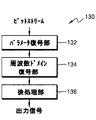
図1A及び図1Bは、本発明が適用されるオーディオ符号化装置及びオーディオ復号装置の一例による構成をそれぞれ示したブロック図である。 1A and 1B are block diagrams each showing a configuration of an example of an audio encoding device and an audio decoding device to which the present invention is applied.
図1Aに図示されたオーディオ符号化装置110は、前処理部112、周波数ドメイン符号化部114及びパラメータ符号化部116を含んでもよい。各構成要素は、少なくとも1以上のモジュールに一体化され、少なくとも1以上のプロセッサ(図示せず)としても具現される。
The
図1Aにおいて、前処理部112は、入力信号に対して、フィルタリングあるいはダウンサンプリングなどを行うことができるが、それらに限定されるものではない。入力信号は、オーディオ、ミュージック、スピーチ、あるいはそれらの混合信号を示すサウンドなどのメディア信号を意味するが、以下では、説明の便宜のために、オーディオ信号とする。
In FIG. 1A, the
周波数ドメイン符号化部114は、前処理部112から提供されるオーディオ信号に対して時間・周波数変換を行い、オーディオ信号のチャンネル数、符号化帯域及びビット率に対応して符号化ツールを選択し、選択された符号化ツールを利用して、オーディオ信号に対する符号化を行うことができる。時間・周波数変換は、MDCT(modified discrete cosine transform)、MLT(modulated lapped transform)あるいはFFT(fast Fourier transform)を使用するが、それらに限定されるものではない。ここで、与えられたビット数が十分な場合、全体帯域に対して一般的な変換符号化方式を適用し、与えられたビット数が十分ではない場合、一部帯域については、帯域拡張方式を適用することができる。一方、オーディオ信号が、ステレオあるいはマルチチャンネルである場合、与えられたビット数が十分であるならば、各チャンネル別に符号化し、十分ではなければ、ダウンミキシング方式を適用することができる。周波数ドメイン符号化部114からは、符号化されたスペクトル係数が生成される。
The frequency
パラメータ符号化部116は、周波数ドメイン符号化部114から提供される符号化されたスペクトル係数からパラメータを抽出し、抽出されたパラメータを符号化することができる。パラメータは、例えば、サブバンド別あるいはバンド別に抽出され、以下では、説明の簡素化のために、サブバンドとする。各サブバンドは、スペクトル係数をグルーピングした単位であり、臨界帯域を反映し、均一長あるいは不均一長を有することができる。不均一長を有する場合、低周波数帯域に存在するサブバンドの場合、高周波数帯域と比較し、相対的に短い長さを有することができる。1フレームに含まれるサブバンドの個数及び長さは、コーデックアルゴリズムによって異なり、符号化性能に影響を及ぼす。一方、パラメータは、サブバンドのスケールファクタ、パワー、平均エネルギーあるいはnormを例として挙げることができるが、それらに限定されるものではない。符号化の結果として得られるスペクトル係数とパラメータは、ビットストリームを形成し、記録媒体に保存されるか、あるいはチャンネルを介して、例えば、パケット状で伝送される。
The parameter encoding unit 116 can extract a parameter from the encoded spectral coefficient provided from the frequency
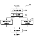
図1Bに図示されたオーディオ復号装置130は、パラメータ復号部132、周波数ドメイン復号部134及び後処理部136を含んでもよい。ここで、周波数ドメイン復号部134は、フレーム消去隠匿(FEC:frame erasure concealment)アルゴリズムあるいはパケット損失隠匿(PLC:packet loss concealment)アルゴリズムを含んでもよい。各構成要素は、少なくとも1以上のモジュールに一体化され、少なくとも1以上のプロセッサ(図示せず)としても具現される。
The
図1Bにおいて、パラメータ復号部132は、受信されたビットストリームから符号化されたパラメータを復号し、復号されたパラメータから、フレーム単位で、消去あるいは損失のようなエラーが発生したか否かということをチェックすることができる。エラーチェックは、公知の多様な方法を使用することができ、現在フレームが正常フレームであるか、あるいは消去フレームまたは損失フレームであるかということに係わる情報を、周波数ドメイン復号部134に提供する。以下では、説明の簡素化のために、消去フレームまたは損失フレームをエラーフレームとする。
In FIG. 1B, a
周波数ドメイン復号部134は、現在フレームが正常フレームである場合、一般的な変換復号過程を介して復号を行い、合成されたスペクトル係数を生成することができる。一方、周波数ドメイン復号部134は、現在フレームがエラーフレームである場合、FECアルゴリズムあるいはPLCアルゴリズムを介して、以前正常フレームのスペクトル係数をエラーフレームに反復して使用するか、あるいは回帰分析を介してスケーリングして反復することにより、合成されたスペクトル係数を生成することができる。周波数ドメイン復号部134は、合成されたスペクトル係数に対して、周波数・時間変換を行い、時間ドメイン信号を生成することができる。
If the current frame is a normal frame, the frequency
後処理部136は、周波数ドメイン復号部134から提供される時間ドメイン信号に対して、音質向上のためのフィルタリングあるいはアップサンプリングなどを行うことができるが、それらに限定されるものではない。後処理部136は、出力信号として、復元されたオーディオ信号を提供する。
The
図2A及び図2Bは、本発明が適用されるオーディオ符号化装置及びオーディオ復号装置の他の例による構成をそれぞれ示したブロック図であり、スイッチング構造を有する。 2A and 2B are block diagrams each showing a configuration of another example of an audio encoding device and an audio decoding device to which the present invention is applied, and have a switching structure.
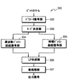
図2Aに図示されたオーディオ符号化装置210は、前処理部212、モード決定部213、周波数ドメイン符号化部214、時間ドメイン符号化部215及びパラメータ符号化部216を含んでもよい。各構成要素は、少なくとも1以上のモジュールに一体化され、少なくとも1以上のプロセッサ(図示せず)としても具現される。
The
図2Aにおいて、前処理部212は、図1Aの前処理部112と実質的に同一であるので、説明を省略する。
In FIG. 2A, the
モード決定部213は、入力信号の特性を参照し、符号化モードを決定することができる。入力信号の特性によって、現在フレームに適する符号化モードが、音声モードであるか、あるいは音楽モードであるかということを決定することができ、また現在フレームに効率的な符号化モードが、時間ドメインモードであるか、あるいは周波数ドメインモードであるかということを決定することができる。ここで、フレームの短区間特性、あるいは複数のフレームに対する長区間特性などを利用して、入力信号の特性を把握することができるが、それに限定されるものではない。例えば、入力信号が音声信号に該当すれば、音声モードあるいは時間ドメインモードに決定し、入力信号が音声信号以外の信号、すなわち、音楽信号あるいは混合信号に該当すれば、音楽モードあるいは周波数ドメインモードに決定することができる。モード決定部213は、入力信号の特性が音楽モードあるいは周波数ドメインモードに該当する場合には、前処理部212の出力信号を周波数ドメイン符号化部214に提供し、入力信号の特性が音声モードあるいは時間ドメインモードに該当する場合、時間ドメイン符号化部215に提供することができる。
The
周波数ドメイン符号化部214は、図1Aの周波数ドメイン符号化部114と実質的に同一であるので、説明を省略する。
The frequency
時間ドメイン符号化部215は、前処理部212から提供されるオーディオ信号に対して、CELP(code excited linear prediction)符号化を行うことができる。具体的には、ACELP(algebraic CELP)を使用することができるが、それに限定されるものではない。
The time
パラメータ符号化部216は、周波数ドメイン符号化部214あるいは時間ドメイン符号化部215から提供される符号化されたスペクトル係数からパラメータを抽出し、抽出されたパラメータを符号化する。パラメータ符号化部216は、図1Aのパラメータ符号化部116と実質的に同一であるので、説明を省略する。符号化の結果として得られるスペクトル係数とパラメータは、符号化モード情報と共にビットストリームを形成し、チャネルを介してパケット状で伝送されるか、あるいは記録媒体に保存される。
The
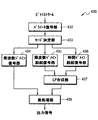
図2Bに図示されたオーディオ復号装置230は、パラメータ復号部232、モード決定部233、周波数ドメイン復号部234、時間ドメイン復号部235及び後処理部236を含んでもよい。ここで、周波数ドメイン復号部234と時間ドメイン復号部235は、それぞれ当該ドメインでのFECアルゴリズムあるいはPLCアルゴリズムを含んでもよい。各構成要素は、少なくとも1以上のモジュールに一体化され、少なくとも1以上のプロセッサ(図示せず)としても具現される。
The
図2Bにおいて、パラメータ復号部232は、パケット状で伝送されるビットストリームからパラメータを復号し、復号されたパラメータから、フレーム単位でエラーが発生したか否かということをチェックすることができる。エラーチェックは、公知の多様な方法を使用することができ、現在フレームが正常フレームであるか、あるいはエラーフレームであるかということに係わる情報を、周波数ドメイン復号部234あるいは時間ドメイン復号部235に提供する。
In FIG. 2B, a
モード決定部233は、ビットストリームに含まれた符号化モード情報をチェックし、現在フレームを周波数ドメイン復号部234あるいは時間ドメイン復号部235に提供する。
The
周波数ドメイン復号部234は、符号化モードが音楽モードあるいは周波数ドメインモードである場合に動作し、現在フレームが正常フレームである場合、一般的な変換復号過程を介して復号を行い、合成されたスペクトル係数を生成する。一方、現在フレームがエラーフレームであり、以前フレームの符号化モードが音楽モードあるいは周波数ドメインモードである場合、周波数ドメインでのFECアルゴリズムあるいはPLCアルゴリズムを介して、以前正常フレームのスペクトル係数をエラーフレームに反復して使用するか、あるいは回帰分析を介してスケーリングして反復することにより、合成されたスペクトル係数を生成することができる。周波数ドメイン復号部234は、合成されたスペクトル係数に対して周波数・時間変換を行い、時間ドメイン信号を生成することができる。
The frequency
時間ドメイン復号部235は、符号化モードが音声モードあるいは時間ドメインモードである場合に動作し、現在フレームが正常フレームである場合、一般的なCELP復号過程を介して復号を行い、時間ドメイン信号を生成する。一方、現在フレームがエラーフレームであり、以前フレームの符号化モードが音声モードあるいは時間ドメインモードである場合、時間ドメインでのFECアルゴリズムあるいはPLCアルゴリズムを遂行することができる。
The time
後処理部236は、周波数ドメイン復号部234あるいは時間ドメイン復号部235から提供される時間ドメイン信号に対して、フィルタリングあるいはアップサンプリングなどを行うことができるが、それらに限定されるものではない。後処理部236は、出力信号として、復元されたオーディオ信号を提供する。
The
図3A及び図3Bは、本発明が適用されるオーディオ符号化装置及びオーディオ復号装置の他の例による構成をそれぞれ示したブロック図であり、スイッチング構造を有する。 FIGS. 3A and 3B are block diagrams each showing a configuration of another example of an audio encoding device and an audio decoding device to which the present invention is applied, and have a switching structure.
図3Aに図示されたオーディオ符号化装置310は、前処理部312、LP(linear prediction)分析部313、モード決定部314、周波数ドメイン励起符号化部315、時間ドメイン励起符号化部316及びパラメータ符号化部317を含んでもよい。各構成要素は、少なくとも1以上のモジュールに一体化され、少なくとも1以上のプロセッサ(図示せず)としても具現される。
The
図3Aにおいて、前処理部312は、図1Aの前処理部112と実質的に同一であるので、説明を省略する。
In FIG. 3A, the
LP分析部313は、入力信号に対してLP分析を行ってLP係数を抽出し、抽出されたLP係数から励起信号を生成する。該励起信号は、符号化モードによって、周波数ドメイン励起符号化部315と時間ドメイン励起符号化部316とのうちいずれか一方に提供される。
モード決定部314は、図2Bのモード決定部213と実質的に同一であるので、説明を省略する。
The
周波数ドメイン励起符号化部315は、符号化モードが音楽モードあるいは周波数ドメインモードである場合に動作し、入力信号が励起信号であることを除いては、図1Aの周波数ドメイン符号化部114と実質的に同一であるので、説明を省略する。
The frequency domain
時間ドメイン励起符号化部316は、符号化モードが音声モードあるいは時間ドメインモードである場合に動作し、入力信号が励起信号であることを除いては、図2Aの時間ドメイン符号化部215と実質的に同一であるので、説明を省略する。
The time domain
パラメータ符号化部317は、周波数ドメイン励起符号化部315あるいは時間ドメイン励起符号化部316から提供される符号化されたスペクトル係数からパラメータを抽出し、抽出されたパラメータを符号化する。パラメータ符号化部317は、図1Aのパラメータ符号化部116と実質的に同一であるので、説明を省略する。符号化の結果として得られるスペクトル係数とパラメータは、符号化モード情報と共にビットストリームを形成し、チャネルを介してパケット状で伝送されるか、あるいは記録媒体に保存される。
The parameter coding unit 317 extracts parameters from the coded spectral coefficients provided from the frequency domain
図3Bに図示されたオーディオ復号装置330は、パラメータ復号部332、モード決定部333、周波数ドメイン励起復号部334、時間ドメイン励起復号部335、LP合成部336及び後処理部337を含んでもよい。ここで、周波数ドメイン励起復号部334と時間ドメイン励起復号部335は、それぞれ当該ドメインでのFECアルゴリズムあるいはPLCアルゴリズムを含んでもよい。各構成要素は、少なくとも1以上のモジュールに一体化され、少なくとも1以上のプロセッサ(図示せず)としても具現される。
3B may include a
図3Bにおいて、パラメータ復号部332は、パケット状で伝送されるビットストリームからパラメータを復号し、復号されたパラメータから、フレーム単位でエラーが発生したか否かということをチェックすることができる。エラーチェックは、公知の多様な方法を使用することができ、現在フレームが正常フレームであるか、あるいはエラーフレームであるかということに係わる情報を、周波数ドメイン励起復号部334あるいは時間ドメイン励起復号部335に提供する。
In FIG. 3B, the
モード決定部333は、ビットストリームに含まれた符号化モード情報をチェックし、現在フレームを周波数ドメイン励起復号部334あるいは時間ドメイン励起復号部335に提供する。
The
周波数ドメイン励起復号部334は、符号化モードが音楽モードあるいは周波数ドメインモードである場合に動作し、現在フレームが正常フレームである場合、一般的な変換復号過程を介して復号を行い、合成されたスペクトル係数を生成する。一方、現在フレームがエラーフレームであり、以前フレームの符号化モードが音楽モードあるいは周波数ドメインモードである場合、周波数ドメインでのFECアルゴリズムあるいはPLCアルゴリズムを介して、以前正常フレームのスペクトル係数をエラーフレームに反復して使用するか、あるいは回帰分析を介してスケーリングして反復することにより、合成されたスペクトル係数を生成することができる。周波数ドメイン励起復号部334は、合成されたスペクトル係数に対して周波数・時間変換を行い、時間ドメイン信号である励起信号を生成することができる。
The frequency domain
時間ドメイン励起復号部335は、符号化モードが音声モードあるいは時間ドメインモードである場合に動作し、現在フレームが正常フレームである場合、一般的なCELP復号過程を介して復号を行い、時間ドメイン信号である励起信号を生成する。一方、現在フレームがエラーフレームであり、以前フレームの符号化モードが音声モードあるいは時間ドメインモードである場合、時間ドメインでのFECアルゴリズムあるいはPLCアルゴリズムを遂行することができる。
The time domain
LP合成部336は、周波数ドメイン励起復号部334あるいは時間ドメイン励起復号部335から提供される励起信号に対してLP合成を行い、時間ドメイン信号を生成する。
The
後処理部337は、LP合成部336から提供される時間ドメイン信号に対して、フィルタリングあるいはアップサンプリングなどを行うことができるが、それらに限定されるものではない。後処理部337は、出力信号として、復元されたオーディオ信号を提供する。
The
図4A及び図4Bは、本発明が適用されるオーディオ符号化装置及びオーディオ復号装置の他の例による構成をそれぞれ示したブロック図であり、スイッチング構造を有する。 4A and 4B are block diagrams each showing a configuration of another example of an audio encoding device and an audio decoding device to which the present invention is applied, and have a switching structure.
図4Aに図示されたオーディオ符号化装置410は、前処理部412、モード決定部413、周波数ドメイン符号化部414、LP分析部415、周波数ドメイン励起符号化部416、時間ドメイン励起符号化部417及びパラメータ符号化部418を含んでもよい。各構成要素は、少なくとも1以上のモジュールに一体化され、少なくとも1以上のプロセッサ(図示せず)としても具現される。図4Aに図示されたオーディオ符号化装置410は、図2Aのオーディオ符号化装置210と、図3Aのオーディオ符号化装置310とを結合したものと見ることができるので、共通部分の動作説明は省略する一方、モード決定部413の動作について説明する。
The
モード決定部413は、入力信号の特性及びビット率を参照し、入力信号の符号化モードを決定することができる。モード決定部413は、入力信号の特性によって、現在フレームが音声モードであるか、あるいは音楽モードであるかということにより、また現在フレームに効率的な符号化モードが時間ドメインモードであるか、あるいは周波数ドメインモードであるかということによって、CELPモードと、それ以外のモードとに決定することができる。もし入力信号の特性が音声モードである場合には、CELPモードに決定し、音楽モードでありながら、高ビット率である場合、FDモードに決定し、音楽モードでありながら、低ビット率である場合、オーディオモードに決定することができる。モード決定部413は、FDモードである場合、入力信号を周波数ドメイン符号化部414に提供し、オーディオモードである場合、LP分析部415を介して、周波数ドメイン励起符号化部416に提供し、CELPモードである場合、LP分析部415を介して、時間ドメイン励起符号化部417に提供することができる。
The
周波数ドメイン符号化部414は、図1Aのオーディオ符号化装置110の周波数ドメイン符号化部114、あるいは図2Aのオーディオ符号化装置210の周波数ドメイン符号化部214に対応し、周波数ドメイン励起符号化部416あるいは時間ドメイン励起符号化部417は、図3Aのオーディオ符号化装置310の周波数ドメイン励起符号化部315あるいは時間ドメイン励起符号化部316に対応する。
The frequency
図4Bに図示されたオーディオ復号装置430は、パラメータ復号部432、モード決定部433、周波数ドメイン復号部434、周波数ドメイン励起復号部435、時間ドメイン励起復号部436、LP合成部437及び後処理部438を含んでもよい。ここで、周波数ドメイン復号部434、周波数ドメイン励起復号部435及び時間ドメイン励起復号部436は、それぞれ当該ドメインでのFECアルゴリズムあるいはPLCアルゴリズムを含んでもよい。各構成要素は、少なくとも1以上のモジュールに一体化され、少なくとも1以上のプロセッサ(図示せず)としても具現される。図4Bに図示されたオーディオ復号装置430は、図2Bのオーディオ復号装置230と、図3Bのオーディオ復号装置330とを結合したものと見ることができるので、共通部分の動作説明は省略する一方、モード決定部433の動作について説明する。
The
モード決定部433は、ビットストリームに含まれた符号化モード情報をチェックし、現在フレームを周波数ドメイン復号部434、周波数ドメイン励起復号部435あるいは時間ドメイン励起復号部436に提供する。
The
周波数ドメイン復号部434は、図1Bのオーディオ符号化装置130の周波数ドメイン復号部134、あるいは図2Bのオーディオ復号装置230の周波数ドメイン復号部234に対応し、周波数ドメイン励起復号部435あるいは時間ドメイン励起復号部436は、図3Bのオーディオ復号装置330の周波数ドメイン励起復号部334あるいは時間ドメイン励起復号部335に対応する。
The frequency
図5は、本発明が適用される周波数ドメインオーディオ符号化装置の構成を示したブロック図である。 FIG. 5 is a block diagram showing a configuration of a frequency domain audio encoding device to which the present invention is applied.
図5に図示された周波数ドメインオーディオ符号化装置510は、トランジェント検出部511、変換部512、信号分類部513、エネルギー符号化部514、スペクトル正規化部515、ビット割当て部516、スペクトル符号化部517及び多重化部518を含んでもよい。各構成要素は、少なくとも1以上のモジュールに一体化され、少なくとも1以上のプロセッサ(図示せず)としても具現される。ここで、周波数ドメインオーディオ符号化装置510は、図2に図示された周波数ドメイン符号化部214の全ての機能と、パラメータ符号化部216の一部機能とを遂行することができる。一方、周波数ドメインオーディオ符号化装置510は、信号分類部513を除いては、ITU−T G.719標準に開示されたエンコーダの構成で代替され、そのとき、変換部512は、50%のオーバーラップ区間を有する変換ウィンドウを使用することができる。また、周波数ドメインオーディオ符号化装置510は、トランジェント検出部511及び信号分類部513を除いては、ITU−T G.719標準に開示されたエンコーダの構成でも代替される。各場合において、図示されてはいないが、ITU−T G.719標準のように、スペクトル符号化部517の後端に、ノイズレベル推定部をさらに具備し、ビット割当て過程において、ゼロビットが割り当てられたスペクトル係数のためのノイズレベルを推定してビットストリームに含めることができる。
The frequency domain
図5を参照すれば、トランジェント検出部511は、入力信号を分析し、トランジェント特性を示す区間を検出し、検出結果に対応して、各フレームに対するトランジェントシグナリング情報を生成することができる。そのとき、トランジェント区間の検出には、公知の多様な方法を使用することができる。一実施形態によれば、トランジェント検出部511は、まず、現在フレームがトランジェントフレームであるか否かということを一次的に判断し、トランジェントフレームであると判断された現在フレームに対して、二次的に検証を行う。トランジェントシグナリング情報は、多重化部518を介して、ビットストリームに含まれる一方、変換部512に提供される。
Referring to FIG. 5, the
変換部512は、トランジェント区間の検出結果によって、変換に使用されるウィンドウサイズを決定し、決定されたウィンドウサイズに基づいて、時間・周波数変換を行う。一例として、トランジェント区間が検出されたサブバンドの場合、短区間ウィンドウ(short window)を適用し、検出されていないサブバンドの場合、長区間ウィンドウ(long window)を適用することができる。他の例として、トランジェント区間を含むフレームについて、短区間ウィンドウを適用することができる。
The
信号分類部513は、変換部512から提供されるスペクトルをフレーム単位に分析し、各フレームがハーモニックフレームに該当するか否かということを判断することができる。そのとき、ハーモニックフレームの判断には、公知の多様な方法を使用することができる。一実施形態によれば、信号分類部513は、変換部512から提供されるスペクトルを複数のサブバンドに分け、各サブバンドに対して、エネルギーのピーク値と平均値とを求めることができる。次に、各フレームに対して、エネルギーのピーク値が平均値より所定比率以上大きいサブバンドの数を求め、求められたサブバンドの数が、所定値以上であるフレームをハーモニックフレームと決定することができる。ここで、所定比率及び所定値は、実験あるいはシミュレーションを介して、前もって決定することができる。ハーモニックシグナリング情報は、多重化部518を介し、てビットストリームに含まれてもよい。
The
エネルギー符号化部514は、各サブバンド単位でエネルギーを求め、量子化及び無損失符号化することができる。一実施形態によれば、エネルギーとして、各サブバンドの平均スペクトルエネルギーに該当するNorm値を使用することができ、スケールファクタあるいはパワーを代わりに使用することができるが、それらに限定されるものではない。ここで、各サブバンドのNorm値は、スペクトル正規化部515及びビット割当て部516に提供される一方、多重化部518を介して、ビットストリームに含まれてもよい。
The
スペクトル正規化部515は、各サブバンド単位で求められたNorm値を利用して、スペクトルを正規化することができる。
The
ビット割当て部516は、各サブバンド単位で求められたNorm値を利用して、整数単位あるいは小数点単位で、ビット割り当てを行うことができる。また、ビット割当て部516は、各サブバンド単位で求められたNorm値を利用して、マスキング臨界値を計算し、マスキング臨界値を利用して、知覚的に必要なビット数、すなわち、許容ビット数を推定することができる。次に、ビット割当て部516は、各サブバンドに対して、割当てビット数が許容ビット数を超えないように制限することができる。一方、ビット割当て部516は、Norm値が大きいサブバンドから順次にビットを割り当て、各サブバンドのNorm値に対して、各サブバンドの知覚的重要度によって、加重値を付与することにより、知覚的に重要なサブバンドに、さらに多くのビットが割り当てられるように調整することができる。そのとき、Norm符号化部514からビット割当て部516に提供される量子化されたNorm値は、ITU−T G.719と同様に、心理音響加重(psycho-acoustical weighting)及びマスキング効果を考慮するために、あらかじめ調整された後、ビット割り当てに使用される。
The
スペクトル符号化部517は、正規化されたスペクトルに対して、各サブバンドの割当てビット数を利用して量子化を行い、量子化された結果に対して、無損失符号化を行うことができる。一例として、スペクトル符号化に、TCQ(trellis coded quantizer)、USQ(uniform scalar quantizer)、FPC(factorial puls ecoder)、AVQ(analog vector quantizer)、PVQ(predictive vector quantizer)、あるいはそれらの組み合わせと、各量子化器に対応する無損失符号化器とを使用することができる。また、当該コーデックが搭載される環境、あるいはユーザの必要によって、多様なスペクトル符号化技法を適用することができる。スペクトル符号化部517で符号化されたスペクトルに係わる情報は、多重化部518を介して、ビットストリームに含まれてもよい。
The
図6は、本発明が適用される周波数ドメインオーディオ符号化装置の構成を示したブロック図である。図6に図示されたオーディオ符号化装置600は、前処理部610、周波数ドメイン符号化部630、時間ドメイン符号化部650及び多重化部670を含んでもよい。周波数ドメイン符号化部630は、トランジェント検出部631、変換部633及びスペクトル符号化部635を含んでもよい。各構成要素は、少なくとも1以上のモジュールに一体化され、少なくとも1以上のプロセッサ(図示せず)としても具現される。
FIG. 6 is a block diagram showing a configuration of a frequency domain audio encoding device to which the present invention is applied. The
図6において、前処理部610は、入力信号に対して、フィルタリングあるいはダウンサンプリングなどを行うことができるが、それらに限定されるものではない。前処理部610は、信号特性に基づいて、符号化モードを決定することができる。信号特性によって、現在フレームに適する符号化モードが、音声モードであるか、あるいは音楽モードであるかということを決定することができ、また現在フレームに効率的な符号化モードが、時間ドメインモードであるか、あるいは周波数ドメインモードであるかということを決定することができる。ここで、フレームの短区間特性、あるいは複数のフレームに対する長区間特性などを利用して、信号特性を把握することができるが、それに限定されるものではない。例えば、入力信号が音声信号に該当すれば、音声モードあるいは時間ドメインモードに決定し、入力信号が音声信号以外の信号、すなわち、音楽信号あるいは混合信号に該当すれば、音楽モードあるいは周波数ドメインモードに決定することができる。前処理部610は、信号特性が音楽モードあるいは周波数ドメインモードに該当する場合には、入力信号を周波数ドメイン符号化部630に提供し、信号特性が音声モードあるいは時間ドメインモードに該当する場合、入力信号を時間ドメイン符号化部650に提供することができる。
In FIG. 6, the
周波数ドメイン符号化部630は、前処理部610から提供されるオーディオ信号を、変換符号化に基づいて処理することができる。具体的には、トランジェント検出部631は、オーディオ信号からトランジェント成分を検出し、現在フレームがトランジェントフレームであるか否かということを判断することができる。変換部633は、トランジェント検出部631から提供されるフレームタイプ、すなわち、トランジェント情報に基づいて、変換ウィンドウの長さあるいは形態を決定し、決定された変換ウィンドウに基づいて、オーディオ信号を周波数ドメインに変換することができる。変換技法としては、MDCT、FFTあるいはMLTを適用することができる。一般的に、トランジェント成分を有するフレームについては、短い長さの変換ウィンドウを適用することができる。スペクトル符号化部635は、周波数ドメインに変換されたオーディオスペクトルに対して、符号化を行うことができる。スペクトル符号化部635については、図7及び図9を参照し、さらに具体的に説明する。
The frequency
時間ドメイン符号化部650は、前処理部610から提供されるオーディオ信号に対して、CELP(code excited linear prediction)符号化を行うことができる。具体的には、ACELP(algebraic CELP)を使用することができるが、それらに限定されるものではない。
The time
多重化部670は、周波数ドメイン符号化部630あるいは時間ドメイン符号化部650において、符号化の結果として生成されるスペクトル成分あるいは信号成分と、多様なインデックスとを多重化してビットストリームを生成し、ビットストリームは、チャネルを介してパケット状で伝送されるか、あるいは記録媒体に保存される。
The
図7は、一実施形態によるスペクトル符号化装置の構成を示すブロック図である。図7に図示された装置は、図6のスペクトル符号化部635に対応するか、他の周波数ドメイン符号化装置に含まれるか、あるいは独立しても具現される。
FIG. 7 is a block diagram illustrating a configuration of the spectrum encoding device according to the embodiment. The apparatus shown in FIG. 7 corresponds to the
図7に図示されたスペクトル符号化装置700は、エネルギー推定部710、エネルギー量子化及び符号化部720、ビット割当て部730、スペクトル正規化部740、スペクトル量子化及び符号化部750及びノイズフィリング部760を含んでもよい。
7 includes an
図7を参照すれば、エネルギー推定部710は、本来のスペクトル係数をサブバンドに分離し、各サブバンド別エネルギー、例えば、Norm値を推定することができる。ここで、1つのフレームにおいて、各サブバンドは、同一大きさを有するか、低域から高域に行くほど、各サブバンドに含まれるスペクトル係数の数を増加させることができる。
Referring to FIG. 7, the
エネルギー量子化及び符号化部720は、各サブバンドについて推定されたNorm値を量子化及び符号化することができる。そのとき、Norm値は、ベクトル量子化、スカラー量子化、TCQ、LVQ(lattice vector quantization)など多様な方式によって量子化される。エネルギー量子化及び符号化部720は、さらなる符号化効率を向上させるために、無損失符号化をさらに行うことができる。
The energy quantization and
ビット割当て部730は、サブバンド別に量子化されたNorm値を利用して、フレーム当たり許容ビットを考慮しながら、符号化に必要なビットを割り当てることができる。
The
スペクトル正規化部740は、サブバンド別に量子化されたNorm値を利用して、スペクトルに対する正規化を行うことができる。
The
スペクトル量子化及び符号化部750は、正規化されたスペクトルに対して、サブバンド別に割り当てられたビットに基づいて、量子化及び符号化を行うことができる。
The spectrum quantization and
ノイズフィリング部760は、スペクトル量子化及び符号化部750において、許容ビットの制約によって0に量子化された部分に、適切なノイズを追加することができる。
The
図8は、サブバンド分割の例を示す図面である。図8を参照すれば、入力信号が、48kHzのサンプリング周波数を使用し、20msのフレーム大きさを有する場合、毎フレーム当たり処理するサンプルの個数は、960個になる。すなわち、入力信号を、MDCTを利用して、50%のオーバーラッピングを適用して変換すれば、960個のスペクトル係数が得られる。ここで、オーバーラッピングの比率は、符号化方式によって多様に設定される。周波数ドメインでは、理論的に、24kHzまで処理可能であるが、人間の可聴帯域を考慮し、20kHzまでの帯域を表現する。低域である0〜3.2kHzまでは、8個のスペクトル係数を1つのサブバンドにまとめて使用し、3.2〜6.4kHzの帯域では、16個のスペクトル係数を1つのサブバンドにまとめて使用する。6.4〜13.6kHzの帯域では、24個のスペクトル係数を1つのサブバンドにまとめて使用し、13.6〜20kHzの帯域では、32個のスペクトル係数を、1つのサブバンドにまとめて使用する。実際のNorm値を求めて符号化を行う場合、符号化器において決められた帯域までNormを求めて符号化することができる。決定された帯域後の特定高域では、帯域拡張のような多様な方式に基づいた符号化が可能である。 FIG. 8 is a diagram illustrating an example of subband division. Referring to FIG. 8, when an input signal uses a sampling frequency of 48 kHz and has a frame size of 20 ms, the number of samples to be processed per frame is 960. That is, if the input signal is converted by applying 50% overlapping using MDCT, 960 spectral coefficients can be obtained. Here, the overlapping ratio is variously set according to the coding method. In the frequency domain, it is theoretically possible to process up to 24 kHz, but a band up to 20 kHz is expressed in consideration of the human audible band. From 0 to 3.2 kHz, which is a low frequency band, eight spectral coefficients are collectively used in one subband, and in the band of 3.2 to 6.4 kHz, 16 spectral coefficients are used in one subband. Use together. In the band of 6.4 to 13.6 kHz, 24 spectral coefficients are collectively used in one subband, and in the band of 13.6 to 20 kHz, 32 spectral coefficients are collected in one subband. use. When encoding is performed by obtaining an actual Norm value, it is possible to obtain Norm up to a band determined by an encoder and perform encoding. In a specific high band after the determined band, encoding based on various schemes such as band extension is possible.
図9は、一実施形態によるスペクトル量子化装置の構成を示すブロック図である。図9に図示された装置は、量子化器選択部910)、USQ 930及びTCQ 950を含んでもよい。
FIG. 9 is a block diagram illustrating a configuration of the spectrum quantization device according to the embodiment. The apparatus illustrated in FIG. 9 may include a quantizer selection unit 910),
図9において、量子化器選択部910は、入力信号、すなわち、量子化される信号の特性によって、多様な量子化器のうち最も効率的な量子化器を選択することができる。入力信号の特性としては、バンド別ビット割当て情報、バンドの大きさ情報などが使用可能である。選択結果によって、量子化される信号をUSQ 930及びTCQ 950のうち一つに提供され、対応する量子化を行うことができる。
Referring to FIG. 9, a
図10は、一実施形態によるスペクトル符号化装置の構成を示すブロック図である。図10に図示された装置は、図7のスペクトル量子化及び符号化部750に対応するか、他の周波数ドメイン符号化装置に含まれるか、あるいは独立しても具現される。
FIG. 10 is a block diagram illustrating a configuration of the spectrum encoding device according to the embodiment. The device illustrated in FIG. 10 corresponds to the spectrum quantization and
図10に図示された装置は、符号化方式選択部1010、ゼロ符号化部1020、スケーリング部1030、ISC符号化部1040、量子化成分復元部1050及び逆スケーリング部1060を含んでもよい。ここで、量子化成分復元部1050及び逆スケーリング部1060は、オプションとして具備される。
The apparatus illustrated in FIG. 10 may include a coding
図10において、符号化方式選択部1010は、入力信号特性を考慮し、符号化方式を選択することができる。入力信号特性は、バンド別に割り当てられたビットを含んでもよい。正規化されたスペクトルは、バンド別に選択された符号化方式に基づいて、ゼロ符号化部1020あるいはスケーリング部1030に提供される。一実施形態によれば、バンドの各サンプルに割り当てられた平均ビット数が、所定値、例えば、0.75以上である場合、当該バンドは、非常に重要であると判断され、USQが使用される一方、全ての他のバンドは、TCQが使用される。ここで、平均ビット数は、バンド長あるいはバンド大きさを考慮して決定することができる。選択された符号化方式は、1ビットのフラグを利用して設定される。
In FIG. 10, a coding
ゼロ符号化部1020は、割り当てられたビットが0であるバンドに対して、全てのサンプルを0に符号化することができる。
The zero
スケーリング部1030は、バンドに割り当てられたビットに基づいて、スペクトルに対するスケーリングを行うことにより、ビット率を調節することができる。そのとき、正規化されたスペクトルが使用される。スケーリング部1030は、バンドに含まれた各サンプル、すなわち、スペクトル係数に割り当てられた平均ビット数を考慮し、スケーリングを行うことができる。例えば、平均ビット数が多いほど、さらに大きいスケーリングが行われる。
The
一実施形態によれば、スケーリング部1030は、バンド別にビット割り当てによって、適切なスケーリング値を決定することができる。
According to an exemplary embodiment, the
具体的には、まず、バンド長(band length)及びビット割当て情報を利用して、現在バンドのためのパルス個数を推定することができる。ここで、パルスは、単位パルスを意味する。まず、下記数式(1)に基づいて、現在バンドで実際に必要なビットbを算出することができる。 Specifically, first, the number of pulses for the current band can be estimated using the band length and the bit allocation information. Here, the pulse means a unit pulse. First, the bit b actually required in the current band can be calculated based on the following equation (1).

一方、ノンゼロ位置の個数は、例えば、下記数式(2)のように、確率に基づいて得られる。 On the other hand, the number of non-zero positions is obtained based on a probability, for example, as in the following equation (2).
次に、バンド別に求められたパルス個数推定値と、入力信号の絶対値とを利用して、初期スケーリングファクタを決定することができる。入力信号は、初期スケーリングファクタによってスケーリングされる。もしスケーリングされた原信号、すなわち、量子化された信号に対するパルス個数の和がパルス個数推定値の同じではない場合には、アップデートされたスケーリングファクタを利用して、パルス再分配(redistribution)処理を行うことができる。パルス再分配処理は、現在バンドに対して選択されたパルス個数が、バンド別に求められたパルス個数推定値より少ない場合には、スケーリングファクタを減少させてパルス個数を増加させ、反対に多い場合には、スケーリングファクタを増加させてパルス個数を減少させる。そのとき、原信号との歪曲を最小化する位置を選択し、あらかじめ決定された値ほど増加させるか、あるいは減少させることができる。 Next, an initial scaling factor can be determined using the pulse number estimated value obtained for each band and the absolute value of the input signal. The input signal is scaled by the initial scaling factor. If the sum of the pulse numbers for the scaled original signal, ie, the quantized signal, is not the same as the pulse number estimate, a pulse redistribution process is performed using the updated scaling factor. It can be carried out. The pulse redistribution process increases the number of pulses by decreasing the scaling factor if the number of pulses selected for the current band is less than the estimated number of pulses determined for each band, Reduces the number of pulses by increasing the scaling factor. At this time, a position where distortion with the original signal is minimized is selected, and the position can be increased or decreased by a predetermined value.
TSQのための歪曲関数は、正確な距離よりは、相対的な大きさを必要とするために、下記の数式(4)のように、各バンドにおいて、それぞれ量子化及び逆量子化された値の自乗距離の和として得られる。 Since the distortion function for TSQ requires a relative size rather than an exact distance, the quantized and dequantized values are respectively calculated for each band as shown in the following equation (4). As the sum of the squared distances of
一方、USQのための歪曲関数は、最善の量子化された値を決定するために、ユークリッド距離を使用することができる。そのとき、複雑度を最小化するために、スケーリングファクタを含む修正された数式を使用し、歪曲関数は、下記数式(5)によって算出される。 On the other hand, the distortion function for USQ can use the Euclidean distance to determine the best quantized value. At this time, in order to minimize the complexity, a modified formula including a scaling factor is used, and the distortion function is calculated by the following formula (5).
1つのパルスを加減するために、最適の歪曲値を求めるためのn個の歪曲値を求める必要がある。例えば、歪曲値jは、下記数式(6)のように、バンドにおいてj番目の位置にパルスを追加することに該当する。 In order to add or subtract one pulse, it is necessary to find n distortion values for finding an optimal distortion value. For example, the distortion value j corresponds to adding a pulse to a j-th position in a band as in the following equation (6).
一方、ビット率を制御するために、スケーリングされたスペクトル係数を使用して、適切なISCを選択して符号化することができる。具体的には、量子化するためのスペクトル成分は、各バンドのビット割り当てを使用して選択される。そのとき、スペクトル成分の分布及び分散による多様な組み合わせに基づいて、スペクトル成分を選択することができる。次に、実際のノンゼロ位置を算出することができる。ノンゼロ位置は、スケーリング量と再分配動作とを分析して得ることができ、そのように選択されたノンゼロ位置は、他の言い方でISCとすることができる。要約すれば、スケーリングと再分配過程とを経た信号の大きさを分析し、最適スケーリングファクタと、ISCに該当するノンゼロ位置情報とを求めることができる。ここで、ノンゼロ位置情報は、ノンゼロ位置の個数及び位置を意味する。もしスケーリングと再分配過程とを介して、パルス個数が調節されない場合、選択されたパルスを、実際のTCQ過程を介して量子化し、その結果を利用して、余剰ビットを調整することができる。その過程は、次のような例が可能である。 On the other hand, to control the bit rate, the appropriate ISC can be selected and encoded using the scaled spectral coefficients. Specifically, the spectral components to quantize are selected using the bit allocation for each band. At this time, the spectral components can be selected based on various combinations based on the distribution and dispersion of the spectral components. Next, the actual non-zero position can be calculated. The non-zero position can be obtained by analyzing the scaling amount and the redistribution operation, and the non-zero position so selected can be ISC in other words. In summary, it is possible to determine the optimal scaling factor and the non-zero position information corresponding to the ISC by analyzing the magnitude of the signal that has undergone the scaling and redistribution processes. Here, the non-zero position information means the number and positions of the non-zero positions. If the number of pulses is not adjusted through the scaling and redistribution processes, the selected pulses can be quantized through the actual TCQ process, and the surplus bits can be adjusted using the result. The following example is possible in the process.
ノンゼロ位置数と、バンド別に求められたパルス個数推定値とが同じではなく、ノンゼロ位置の個数が、所定値、例えば、1より大きく求められた量子化器選択情報がTCQを示す条件の場合、実際のTCQ量子化を介して、余剰ビットを調整することができる。具体的には、前記条件に該当する場合、余剰ビットを調整するために、まず、TCQ量子化過程を経る。前もってバンド別に求められたパルス個数推定値に比べ、実際のTCQ量子化を介して求められた現在バンドのパルス個数がさらに少ない場合には、以前に決定されたスケーリングファクタに、1より大きい値、例えば、1.1を乗じてスケーリングファクタを増加させ、反対の場合には、1より少ない値、例えば、0.9を乗じてスケーリングファクタを減少させる。そのような過程を反復し、バンド別に求められたパルス個数推定値と、TCQ量子化を介して求められた現在バンドのパルス個数とが同じになる場合、実際のTCQ量子化過程で使用されたビットを計算し、余剰ビットをアップデートする。そのように求められたノンゼロ位置が、ISCに該当する。 If the number of non-zero positions is not the same as the estimated number of pulses determined for each band, and the number of non-zero positions is a predetermined value, for example, if the quantizer selection information determined to be greater than 1 is a condition indicating TCQ, The surplus bits can be adjusted via actual TCQ quantization. Specifically, if the above condition is satisfied, a TCQ quantization process is first performed to adjust the surplus bits. If the number of pulses in the current band determined through actual TCQ quantization is smaller than the estimated number of pulses determined in advance for each band, the previously determined scaling factor is set to a value greater than 1, For example, multiply by 1.1 to increase the scaling factor and vice versa to decrease the scaling factor by a value less than 1, for example 0.9. Such a process is repeated, and when the pulse number estimated value obtained for each band is equal to the pulse number of the current band obtained through the TCQ quantization, the pulse number is used in the actual TCQ quantization process. Calculate bits and update surplus bits. The non-zero position thus obtained corresponds to the ISC.
ISC符号化部1040では、最終的に選択されたISCの個数情報及びノンゼロ位置情報を符号化することができる。その過程において、符号化効率を高めるために、無損失符号化を適用することもできる。ISC符号化部1040は、割り当てられたビットが0ではないノンゼロバンドに対して選択された量子化器を利用して、符号化を行うことができる。具体的には、ISC符号化部1040は、正規化されたスペクトルに対して、各バンド別にISCを選択し、各バンド別に選択されたISCの情報を、数、位置、大きさ及び符号に基づいて符号化することができる。そのとき、ISCの大きさは、数、位置及び符号とは異なる方式によって符号化することができる。一例を挙げれば、ISCの大きさは、USQ及びTCQのうち一つを利用して量子化して算術符号化する一方、ISCの数、位置及び符号については、算術符号化を行うことができる。特定バンドが重要な情報を含んでいると判断される場合、USQを使用し、そうではない場合、TCQを使用することができる。実施形態によれば、信号特性に基づいて、TCQ及びUSQのうち一つを選択することができる。ここで、信号特性は、各バンドに割り当てられたビットあるいはバンド長を含んでもよい。もしバンドに含まれた各サンプルに割り当てられた平均ビット数が臨界値、例えば、0.75以上である場合、当該バンドは、非常に重要な情報を含んでいると判断することができるので、USQが使用される。一方、バンド長が短い低域の場合にも、必要によっては、USQが使用される。他の実施形態によれば、帯域幅によって、第1ジョイント方式と第2ジョイント方式とのうち一つが使用される。例えば、NB及びWBについては、各バンドに対する本来のビット割当て情報だけではなく、以前に符号化されたバンドからの余剰ビットに対する二次ビット割当て処理をさらに利用して、量子化器選択が行われる第1ジョイント方式が使用され、SWB及びFBについては、USQを使用すると決定されたバンドに対して、LSB(least significant bit)については、TCQを使用する第2ジョイント方式が使用される。第1ジョイント方式において、二次ビット割当て処理は、以前符号化されたバンドからの余剰ビットを分配することにより、2バンドを選択することができる。一方、第2ジョイント方式において、残りのビットは、USQを使用することができる。
The
量子化成分復元部1050は、量子化された成分に、ISCの位置、大きさ及び符号情報を付加し、実際の量子化された成分を復元することができる。ここで、ゼロ位置、すなわち、ゼロに符号化されたスペクトル係数には、0が割り当てられる。
The quantized
逆スケーリング部1060は、復元された量子化成分に対して逆スケーリングを行い、正規化された入力スペクトルと同一レベルの量子化されたスペクトル係数を出力することができる。スケーリング部1030及び逆スケーリング部1060においては、同一スケーリングファクタを使用することができる。
The
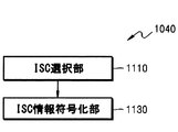
図11は、一実施形態によるISC符号化装置の構成を示すブロック図である。図11に図示された装置は、ISC選択部1110及びISC情報符号化部1130を含んでもよい。図11の装置は、図10のISC符号化部1040に対応するか、あるいは独立した装置として具現される。
FIG. 11 is a block diagram illustrating a configuration of an ISC encoding device according to an embodiment. The apparatus illustrated in FIG. 11 may include an
図11において、ISC選択部1110は、ビット率を調節するために、スケーリングされたスペクトルから、所定基準に基づいてISCを選択することができる。ISC選択部1110は、スケーリングされたスペクトルから、スケーリングされた程度を分析し、実際のノンゼロ位置を求めることができる。ここで、ISCは、スケーリング以前の実際のノンゼロスペクトル係数に該当する。ISC選択部1110は、バンド別に割り当てられたビットに基づいて、スペクトル係数の分布及び分散を考慮し、符号化するスペクトル係数、すなわち、ノンゼロ位置を選択することができる。ISC選択のためにT、CQを使用することができる。
In FIG. 11, an
ISC情報符号化部1130は、選択されたISCに基づいて、ISC情報、すなわち、ISC個数情報、位置情報、大きさ情報及び符号を復号することができる。
The ISC
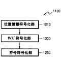
図12は、一実施形態によるISC情報符号化装置の構成を示すブロック図である。図12に図示された装置は、位置情報符号化部1210、大きさ情報符号化部1230及び符号符号化部1250を含んでもよい。
FIG. 12 is a block diagram illustrating a configuration of the ISC information encoding device according to the embodiment. The apparatus illustrated in FIG. 12 may include a position
図12において、位置情報符号化部1210は、ISC選択部1110(図11)で選択されたISCの位置情報、すなわち、ノンゼロスペクトル係数の位置情報を符号化することができる。位置情報は、選択されたISCの数及び位置を含んでもよい。位置情報の符号化には、算術符号化(arithmetic coding)が使用される。一方、選択されたISCを集め、新たなバッファを構成することができる。ISC収集のために、ゼロバンドと、選択されていないスペクトルは、除外される。
12, the position
大きさ情報符号化部1230は、新たに構成されたISCの大きさ情報に対して、符号化を行うことができる。そのとき、TCQ及びUSQのうち一つを選択して量子化を行い、次に、算術符号化を追加して行うことができる。算術符号化の効率を高めるために、ノンゼロ位置情報、及びISCの数が使用される。
The size
符号情報符号化部1250は、選択されたISCの符号情報に対して、符号化を行うことができる。符号情報の符号化には、算術符号化が使用される。
The code
図13は、他の実施形態によるスペクトル符号化装置の構成を示すブロック図である。図13に図示された装置は、図7のスペクトル量子化及び符号化部750に対応するか、他の周波数ドメイン符号化装置に含まれるか、あるいは独立しても具現される。
FIG. 13 is a block diagram illustrating a configuration of a spectrum encoding device according to another embodiment. The apparatus shown in FIG. 13 corresponds to the spectrum quantization and
図13に図示された装置は、スケーリング部1330、ISC符号化部1340、量子化成分復元部1350及び逆スケーリング部1360を含んでもよい。図10と比較するとき、ゼロ符号化部1020と符号化方式選択部1010とが省略され、ISC符号化部1340は、TCQを使用することができるということを除いては、各構成要素の動作は同一である。
The apparatus illustrated in FIG. 13 may include a
図14は、他の実施形態によるスペクトル符号化装置の構成を示すブロック図である。図14に図示された装置は、図7のスペクトル量子化及び符号化部750に対応するか、他の周波数ドメイン符号化装置に含まれるか、あるいは独立しても具現される。
FIG. 14 is a block diagram illustrating a configuration of a spectrum encoding device according to another embodiment. The device illustrated in FIG. 14 corresponds to the spectrum quantization and
図14に図示された装置は、符号化方式選択部1410、スケーリング部1430、ISC符号化部1440、量子化成分復元部1450及び逆スケーリング部1460を含んでもよい。図10と比較するとき、ゼロ符号化部1020が省略されているということを除いては、各構成要素の動作は同一である。
The apparatus illustrated in FIG. 14 may include a coding
図15は、一実施形態によるISC収集過程及び符号化過程の概念を示す図面であり、まず、ゼロバンド(zero band)すなわち、0に量子化されるバンドは除く。次に、ノンゼロバンドに存在するスペクトル成分のうち選択されたISCを利用して、新たなバッファを構成することができる。新たに構成されたISCに対して、バンド単位でTCQを遂行し、対応する無損失符号化(lossless encoding)を行うことができる。 FIG. 15 is a diagram illustrating the concept of an ISC collection process and an encoding process according to an embodiment. First, a zero band, that is, a band quantized to 0 is excluded. Next, a new buffer can be configured using the ISC selected from the spectral components existing in the non-zero band. The newly configured ISC may perform TCQ on a band-by-band basis and perform corresponding lossless encoding.
図16は、他の実施形態によるISC収集過程及び符号化過程ISC収集過程の概念を示す図面であり、まず、ゼロバンド、すなわち、0に量子化されるバンドは除く。次に、ノンゼロバンドに存在するスペクトル成分のうち選択されたISCを利用して、新たなバッファを構成することができる。新たに構成されたISCに対して、バンド単位で、USCあるいはTCQを遂行し、対応する無損失符号化を行うことができる。 FIG. 16 is a diagram illustrating a concept of an ISC collecting process and an encoding process according to another embodiment. First, a zero band, that is, a band quantized to 0 is excluded. Next, a new buffer can be configured using the ISC selected from the spectral components existing in the non-zero band. USC or TCQ can be performed on the newly configured ISC in band units, and corresponding lossless coding can be performed.
図17は、本発明で使用されたTCQの一例を示す図面であり、2つのゼロレベルを有する8ステート4コセットのトレリス構造に該当する。当該TCQについての詳細な説明は、US7605727に開示されている。 FIG. 17 is a diagram illustrating an example of the TCQ used in the present invention, which corresponds to an 8-state 4-coset trellis structure having two zero levels. A detailed description of the TCQ is disclosed in US Pat. No. 7,605,727.
図18は、本発明が適用される周波数ドメインオーディオ復号装置の構成を示したブロック図である。 FIG. 18 is a block diagram showing a configuration of a frequency domain audio decoding device to which the present invention is applied.
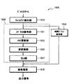
図18に図示された周波数ドメインオーディオ復号装置1800は、フレームエラー検出部1810、周波数ドメイン復号部1830、時間ドメイン復号部1850及び後処理部1870を含んでもよい。周波数ドメイン復号部1830は、スペクトル復号部1831、メモリ更新部1833、逆変換部1835及びOLA(overlap and add)部1837を含んでもよい。各構成要素は、少なくとも1以上のモジュールに一体化され、少なくとも1以上のプロセッサ(図示せず)としても具現される。
The frequency domain
図18を参照すれば、フレームエラー検出部1810は、受信されたビットストリームから、フレームエラーが発生したか否かということを検出することができる。
Referring to FIG. 18, the frame
周波数ドメイン復号部1830は、符号化モードが、音楽モードあるいは周波数ドメインモードである場合に動作し、フレームエラーが発生した場合、FECアルゴリズムあるいはPLCアルゴリズムを動作させ、フレームエラーが発生していない場合、一般的な変換復号過程を介して、時間ドメイン信号を生成する。具体的には、スペクトル復号部1831は、復号されたパラメータを利用してスペクトル復号を行い、スペクトル係数を合成することができる。スペクトル復号部1831については、図19及び図20を参照し、さらに具体的に説明する。
The frequency
メモリ更新部1833は、正常フレームである現在フレームに対して合成されたスペクトル係数、復号されたパラメータを利用して得られた情報、現在まで連続したエラーフレームの個数、各フレームの信号特性あるいはフレームタイプ情報などを、次のフレームのために更新することができる。ここで、信号特性は、トランジェント特性、ステーショナリ特性を含んでもよく、フレームタイプは、トランジェントフレーム、ステーショナリフレームあるいはハーモニックフレームを含んでもよい。
The
逆変換部1835は、合成されたスペクトル係数に対して、時間・周波数逆変換を行い、時間ドメイン信号を生成することができる。
The
OLA部1837は、以前フレームの時間ドメイン信号を利用して、OLA処理を行い、その結果、現在フレームに対する最終時間ドメイン信号を生成し、後処理部1870に提供することができる。
The
時間ドメイン復号部1850は、符号化モードが、音声モードあるいは時間ドメインモードである場合に動作し、フレームエラーが発生した場合、FECアルゴリズムあるいはPLCアルゴリズムを動作させ、フレームエラーが発生していない場合、一般的なCELP復号過程を介して、時間ドメイン信号を生成する。
The time
後処理部1870は、周波数ドメイン復号部1830あるいは時間ドメイン復号部1850から提供される時間ドメイン信号に対して、フィルタリングあるいはアップサンプリングなどを行うことができるが、それらに限定されるものではない。後処理部1670は、出力信号として、復元されたオーディオ信号を提供する。
The
図19は、一実施形態によるスペクトル復号装置の構成を示すブロック図である。図19に図示された装置は、図18のスペクトル復号部1831に対応するか、他の周波数ドメイン復号装置に含まれるか、あるいは独立しても具現される。
FIG. 19 is a block diagram illustrating a configuration of a spectrum decoding device according to one embodiment. The device illustrated in FIG. 19 corresponds to the
図19に図示されたスペクトル復号装置1900は、エネルギー復号及び逆量子化部1910、ビット割当て部1930、スペクトル復号及び逆量子化部1950、ノイズフィリング部1970及びスペクトルシェーピング部1990を含んでもよい。ここで、ノイズフィリング部1970は、スペクトルシェーピング部1990の後端に位置することもできる。各構成要素は、少なくとも1以上のモジュールに一体化され、少なくとも1以上のプロセッサ(図示せず)としても具現される。
The
図19を参照すれば、エネルギー復号及び逆量子化部1910は、符号化過程において無損失符号化が行われたパラメータ、例えば、Norm値のようなエネルギーに対して無損失復号を行い、復号されたNorm値に対して逆量子化を行うことができる。符号化過程において、Norm値の量子化された方式に対応する方式を使用して逆量子化を行うことができる。
Referring to FIG. 19, the energy decoding and
ビット割当て部1930は、量子化されたNorm値、あるいは逆量子化されたNorm値に基づいて、サブバンド別に必要とするビット数を割り当てることができる。その場合、サブバンド単位に割り当てられたビット数は、符号化過程で割り当てられたビット数と同一である。
The
スペクトル復号及び逆量子化部1950は、符号化されたスペクトル係数に対して、サブバンド別に割り当てられたビット数を使用して無損失復号を行い、復号されたスペクトル係数に対して逆量子化過程を行い、正規化されたスペクトル係数を生成することができる。
The spectrum decoding and
ノイズフィリング部1970は、正規化されたスペクトル係数のうち、サブバンド別にノイズフィリングを必要とする部分に対して、ノイズを充填することができる。
The
スペクトルシェーピング部1990は、逆量子化されたNorm値を利用して、正規化されたスペクトル係数をシェーピングすることができる。スペクトルシェーピング過程を介して、最終的に復号されたスペクトル係数が得られる。
The
図20は、一実施形態によるスペクトル逆量子化装置の構成を示すブロック図である。図20に図示された装置は、逆量子化期選択部2010、USQ 2030及びTCQ 2050を含んでもよい。
FIG. 20 is a block diagram illustrating a configuration of the spectrum inverse quantization device according to the embodiment. The apparatus illustrated in FIG. 20 may include an inverse
図20において、逆量子化期選択部2010は、入力信号、すなわち、逆量子化される信号の特性によって、多様な逆量子化器のうち、最も効率的な逆量子化器を選択することができる。入力信号の特性としては、バンド別ビット割当て情報、バンドの大きさ情報などが使用可能である。選択結果によって、逆量子化される信号をUSQ 2030及びTCQ 2050のうち一つに提供し、対応する逆量子化を行うことができる。
In FIG. 20, the inverse quantization
図21は、一実施形態によるスペクトル復号装置の構成を示すブロック図である。図21に図示された装置は、図19のスペクトル復号及び逆量子化部1950に対応するか、他の周波数ドメイン復号装置に含まれるか、あるいは独立しても具現される。
FIG. 21 is a block diagram illustrating a configuration of a spectrum decoding device according to one embodiment. The apparatus shown in FIG. 21 corresponds to the spectrum decoding and
図21に図示された装置は、復号方式選択部2110、ゼロ復号部2130、ISC復号部2150、量子化成分復元部2170及び逆スケーリング部2190を含んでもよい。ここで、量子化成分復元部2170及び逆スケーリング部2190は、オプションとして具備される。
The apparatus illustrated in FIG. 21 may include a decoding
図21において、復号方式選択部2110は、バンド別に割り当てられたビットに基づいて、復号方式を選択することができる。正規化されたスペクトルは、バンド別に選択された復号方式に基づいて、ゼロ復号部2130あるいはISC復号部2150に提供される。
In FIG. 21, decoding
ゼロ復号部2130は、割り当てられたビットが0であるバンドに対して、全てのサンプルを0に復号することができる。
The zero
ISC復号部2150は、割り当てられたビットが0ではないバンドに対して選択された逆量子化器を利用して、復号を行うことができる。ISC復号部2150は、符号化されたスペクトルの各バンド別に、重要周波数成分の情報を得て、各バンド別に得られた重要周波数成分の情報を、数、位置、大きさ及び符号に基づいて復号することができる。重要周波数成分の大きさは、数、位置及び符号とは異なる方式によって復号することができる。一例を挙げれば、重要周波数成分の大きさは、算術復号し、USQ及びTCQのうち一つを利用して逆量子化する一方、重要周波数成分の数、位置及び符号に対して、算術復号を行うことができる。逆量子化器選択は、図10に図示されたISC符号化部1040と同一結果を利用して行うことができる。ISC復号部2150は、割り当てられたビットが0ではないバンドに対して、TCQ及びUSQのうち一つを利用して逆量子化を行うことができる。
The
量子化成分復元部2170は、復元されたISCの位置、大きさ及び符号情報に基づいて、実際の量子化成分を復元することができる。ここで、ゼロ位置、すなわち、ゼロに復号されたスペクトル係数である量子化されていない部分には、0が割り当てられる。
The quantization
さらに、逆スケーリング部(図示せず)を含んで復元された量子化成分に対して、逆スケーリングを行い、正規化されたスペクトルと同一レベルの量子化されたスペクトル係数を出力することができる。 Furthermore, inverse scaling is performed on the restored quantized component including the inverse scaling unit (not shown), and quantized spectral coefficients at the same level as the normalized spectrum can be output.
図22は、一実施形態によるISC復号装置の構成を示すブロック図である。図22の装置は、パルス数推定部2210及びISC情報復号部2230を含んでもよい。図22の装置は、図21のISC復号部2150に対応するか、あるいは独立した装置で具現される。
FIG. 22 is a block diagram illustrating a configuration of the ISC decoding device according to the embodiment. The device in FIG. 22 may include a pulse
図22において、パルス数推定部2210は、バンド大きさとビット割当て情報とを利用して、現在バンドで必要なパルス個数推定値を決定することができる。すなわち、現在フレームのビット割当て情報がエンコーダと同一であるので、同一ビット割当て情報を利用して、同一パルス個数推定値を導き出して復号を進める。
In FIG. 22, a pulse
ISC情報復号部2230は、推定されたパルス数に基づいて、ISC情報、すなわち、ISC個数情報、位置情報、大きさ情報及び符号を復号することができる。
The ISC
図23は、一実施形態によるISC情報復号装置の構成を示すブロック図である。図23に図示された装置は、位置情報復号部2310、大きさ情報復号部2330及び符号復号部2350を含んでもよい。
FIG. 23 is a block diagram showing the configuration of the ISC information decoding device according to one embodiment. The apparatus illustrated in FIG. 23 may include a position
図23において、位置情報復号部2310は、ビットストリームに含まれた位置情報と係わるインデックスを復号し、ISCの数及び位置を復元することができる。位置情報の復号には、算術復号が使用される。大きさ情報復号部2330は、ビットストリームに含まれた大きさ情報と係わるインデックスに対して算術復号を行い、復号されたインデックスに対して、TCQ及びUSQのうち一つを選択し、逆量子化を行うことができる。算術復号の効率を高めるために、ノンゼロ位置情報、及びISCの数が使用される。符号復号部2350は、ビットストリームに含まれた符号情報と係わるインデックスを復号し、ISCの符号を復元することができる。符号情報の復号には、算術復号が使用される。一実施形態によれば、ノンゼロバンドが必要とするパルス数を推定し、位置情報、大きさ情報あるいは符号情報復号に使用することができる。
In FIG. 23, a position
図24は、他の実施形態によるスペクトル復号装置の構成を示すブロック図である。図24に図示された装置は、図19のスペクトル復号及び逆量子化部1950に対応するか、他の周波数ドメイン復号装置に含まれるか、あるいは独立しても具現される。
FIG. 24 is a block diagram illustrating a configuration of a spectrum decoding device according to another embodiment. The apparatus illustrated in FIG. 24 corresponds to the spectrum decoding and
図24に図示された装置は、ISC復号部2450、量子化成分復元部2470及び逆スケーリング部2490を含んでもよい。図21と比較するとき、復号方式選択部2110とゼロ復号部2130とが省略されており、ISC復号部2450がTCQを使用するということを除いては、各構成要素の動作は同一である。
The apparatus illustrated in FIG. 24 may include an
図25は、他の実施形態によるスペクトル復号装置の構成を示すブロック図である。図25に図示された装置は、図19のスペクトル復号及び逆量子化部1950に対応するか、他の周波数ドメイン復号装置に含まれるか、あるいは独立しても具現される。
FIG. 25 is a block diagram illustrating a configuration of a spectrum decoding device according to another embodiment. The apparatus shown in FIG. 25 corresponds to the spectrum decoding and
図25に図示された装置は、復号方式選択部2510、ISC復号部2550、量子化成分復元部2570及び逆スケーリング部2590を含んでもよい。図21と比較するとき、ゼロ復号部2130が省略されているということを除いては、各構成要素の動作は同一である。
The apparatus illustrated in FIG. 25 may include a decoding
図26は、他の実施形態によるISC情報符号化装置の構成を示すブロック図である。図26の装置は、確率算出部2610と無損失符号化部2630とを含んでもよい。
FIG. 26 is a block diagram illustrating a configuration of an ISC information encoding device according to another embodiment. The device in FIG. 26 may include a
図26において、確率算出部2610は、ISC個数、パルス個数、TCQ情報を利用して、下記数式(8),(9)によって、大きさ符号化のための確率値を計算することができる。
In FIG. 26, the
無損失符号化部2630は、その求められた確率値を利用して、TCQ大きさ情報、すなわち、大きさと経路情報とを無損失符号化することができる。各大きさのパルス個数は、
The
図27は、他の実施形態によるISC情報復号装置の構成を示すブロック図である。図27の装置は、確率算出部2710と無損失復号部2730とを含んでもよい。
FIG. 27 is a block diagram showing a configuration of an ISC information decoding device according to another embodiment. The device in FIG. 27 may include a
図27において、確率算出部2710は、ISC情報(個数i、位置)、TCQ情報、パルス個数m、及びバンドの大きさnを利用して、大きさ(magnitude)符号化のための確率値を計算することができる。それのために、まず、求められたパルス個数とバンド大きさとを利用して、必要なビット情報bを求める。そのとき、前記数式(1)のように求めることができる。その後、求められたビット情報b、ISC個数、ISC位置そしてTCQ情報を利用して、前記数式(8),(9)に基づいて、大きさ符号化のための確率値を計算する。
In FIG. 27, the
無損失復号部2730は、符号化装置と同一に求められた確率値と、伝送されたインデックス情報とを利用して、TCQ大きさ情報、すなわち、大きさ(magnitude)情報と経路(path)情報とを無損失復号することができる。それのために、まず、確率値を利用して、個数情報に係わる算術符号化モデルを作り、その求められたモデルを利用して、TCQ大きさ情報の算術復号を遂行してTCQ大きさ情報を復号する。具体的には、各大きさのパルス個数は、
The
図28は、本発明の一実施形態による符号化モジュールを含むマルチメディア機器の構成を示したブロック図である。 FIG. 28 is a block diagram illustrating a configuration of a multimedia device including an encoding module according to an embodiment of the present invention.
図28に図示されたマルチメディア機器2800は、通信部2810と符号化モジュール2830とを含んでもよい。また、符号化の結果として得られるオーディオビットストリームの用途によって、オーディオビットストリームを保存する保存部2850をさらに含んでもよい。また、マルチメディア機器2800は、マイクロホン2870をさらに含んでもよい。すなわち、保存部2450とマイクロホン2870は、オプションとして具備される。一方、図28に図示されたマルチメディア機器2800は、任意の復号モジュール(図示せず)、例えば、一般的な復号機能を遂行する復号モジュール、あるいは本発明の一実施形態による復号モジュールをさらに含んでもよい。ここで、符号化モジュール2830、マルチメディア機器2800に具備される他の構成要素(図示せず)と共に一体化され、少なくとも1以上のプロセッサ(図示せず)としても具現される。
The
図28を参照すれば、通信部2810は、外部から提供されるオーディオと、符号化されたビットストリームとのうち少なくとも一つを受信するか、復元されたオーディオと、符号化モジュール2830の符号化の結果として得られるオーディオビットストリームとのうち少なくとも一つを送信することができる。 Referring to FIG. 28, the communication unit 2810 receives at least one of an externally provided audio and an encoded bit stream, or recovers the restored audio, and encodes the encoded data by the encoding module 2830. And at least one of the resulting audio bit streams.
通信部2810は、無線インターネット、無線イントラネット、無線電話網、無線LAN(local area network)、Wi−Fi(wireless fidelity)、WFD(Wi−Fi direct)、3G(3rd generation)、4G(4th generation)、ブルートゥース(Bluetooth(登録商標))、赤外線通信(IrDA:infrared data association)、RFID(radio frequency identification)、UWB(ultra wideband)、ジグビー(ZigBee(登録商標))、NFC(near field communication)のような無線ネットワーク、または有線電話網、有線インターネットのような有線ネットワークを介して、外部のマルチメディア機器あるいはサーバとデータを送受信することができるように構成される。 The communication unit 2810 includes a wireless Internet, a wireless intranet, a wireless telephone network, a wireless LAN (local area network), Wi-Fi (wireless fidelity), WFD (Wi-Fi direct), 3G (3rd generation), and 4G (4th generation). , Bluetooth (registered trademark), infrared communication (IrDA: infrared data association), RFID (radio frequency identification), UWB (ultra wideband), ZigBee (ZigBee (registered trademark)), NFC (near field communication) It is configured to be able to transmit and receive data to and from an external multimedia device or server via a simple wireless network or a wired network such as a wired telephone network or a wired Internet.
符号化モジュール2830は、一実施形態によれば、正規化されたスペクトルに対して、各バンド別に重要周波数成分を選択し、各バンド別に選択された重要周波数成分の情報を、数、位置、大きさ及び符号に基づいて符号化することができる。重要周波数成分の大きさは、数、位置及び符号とは異なる方式によって符号化することができ、一例を挙げれば、重要周波数成分の大きさは、USQ及びTCQのうち一つを利用して量子化して算術符号化する一方、重要周波数成分の数、位置及び符号に対して、算術符号化を行うことができる。一実施形態によれば、正規化されたスペクトルを、各バンド別に割り当てられたビットに基づいてスケーリングを行い、スケーリングされたスペクトルに対して、重要周波数成分を選択することができる。 According to an exemplary embodiment, the encoding module 2830 may select an important frequency component for each band with respect to the normalized spectrum, and may transmit information of the important frequency component selected for each band to a number, a position, and a size. It can be encoded based on the magnitude and the sign. The magnitude of the important frequency component can be encoded by a method different from the number, position, and code. For example, the magnitude of the important frequency component is quantized using one of USQ and TCQ. While performing arithmetic coding, the arithmetic coding can be performed on the number, position, and sign of important frequency components. According to an exemplary embodiment, the normalized spectrum may be scaled based on bits allocated to each band, and important frequency components may be selected for the scaled spectrum.
保存部2850は、マルチメディア機器2800の運用に必要な多様なプログラムを保存することができる。
The storage unit 2850 may store various programs necessary for operating the
マイクロホン2870は、ユーザ、あるいは外部のオーディオ信号を符号化モジュール2830に提供することができる。
The
図29は、本発明の一実施形態による復号モジュールを含むマルチメディア機器の構成を示したブロック図である。 FIG. 29 is a block diagram illustrating a configuration of a multimedia device including a decoding module according to an embodiment of the present invention.
図29に図示されたマルチメディア機器2900は、通信部2910と復号モジュール2920とを含んでもよい。また、復号の結果として得られる復元されたオーディオ信号の用途によって、復元されたオーディオ信号を保存する保存部2960をさらに含んでもよい。また、マルチメディア機器2900は、スピーカ2970をさらに含んでもよい。すなわち、保存部2960とスピーカ2970は、オプションとして具備される。一方、図29に図示されたマルチメディア機器2900は、任意の符号化モジュール(図示せず)、例えば、一般的な符号化機能を遂行する符号化モジュール、あるいは本発明の一実施形態による符号化モジュールをさらに含んでもよい。ここで、復号モジュール2920は、マルチメディア機器2900に具備される他の構成要素(図示せず)と共に一体化され、少なくとも1つの以上のプロセッサ(図示せず)としても具現される。
The
図29を参照すれば、通信部2910は、外部から提供される符号化されたビットストリームと、オーディオ信号とのうち少なくとも一つを受信するか、あるいは復号モジュール2920の復号結果として得られる復元されたオーディオ信号と、符号化の結果として得られるオーディオビットストリームとのうち少なくとも一つを送信することができる。一方、通信部2910は、図28の通信部2810と実質的に類似して具現される。
Referring to FIG. 29, the communication unit 2910 may receive at least one of an externally provided encoded bit stream and an audio signal, or may obtain a decoded signal obtained as a decoding result of the
復号モジュール2920は、一実施形態によれば、通信部2910を介して提供されるビットストリームを受信し、符号化されたスペクトルの各バンド別に、重要周波数成分の情報を得て、各バンド別に得られた重要周波数成分の情報を、数、位置、大きさ及び符号に基づいて復号することができる。重要周波数成分の大きさは、数、位置及び符号とは異なる方式によって復号することができ、一例を挙げれば、重要周波数成分の大きさは、算術復号し、USQ及びTCQのうち一つを利用して逆量子化する一方、重要周波数成分の数、位置及び符号に対して、算術復号を行うことができる。
According to one embodiment, the
保存部2960は、復号モジュール2920で生成される復元されたオーディオ信号を保存することができる。一方、保存部2960は、マルチメディア機器2900の運用に必要な多様なプログラムを保存することができる。
The storage unit 2960 may store the restored audio signal generated by the
スピーカー2970は、復号モジュール2920で生成される復元されたオーディオ信号を外部に出力することができる。
The
図30は、本発明の一実施形態による符号化モジュールと復号モジュールとを含むマルチメディア機器の構成を示したブロック図である。 FIG. 30 is a block diagram illustrating a configuration of a multimedia device including an encoding module and a decoding module according to an embodiment of the present invention.
図30に図示されたマルチメディア機器3000は、通信部3010、符号化モジュール3020及び復号モジュール3030を含んでもよい。また、符号化の結果として得られるオーディオビットストリーム、あるいは復号結果として得られる復元されたオーディオ信号の用途によって、オーディオビットストリーム、あるいは復元されたオーディオ信号を保存する保存部3040をさらに含んでもよい。また、マルチメディア機器3000は、マイクロホン3050あるいはスピーカ3060をさらに含んでもよい。ここで、符号化モジュール3020と復号モジュール3030は、マルチメディア機器3000に具備される他の構成要素(図示せず)と共に一体化され、少なくとも1以上のプロセッサ(図示せず)としても具現される。
The
図30に図示された各構成要素は、図28に図示されたマルチメディア機器2800の構成要素、あるいは図29に図示されたマルチメディア機器2900の構成要素と重複するので、その詳細な説明は省略する。
Each component illustrated in FIG. 30 is the same as the component of the
図28ないし図30に図示されたマルチメディア機器2800,2900,3000には、電話、モバイルフォンなどを含む音声通信専用端末;TV(television)、MP3プレーヤなどを含む放送専用装置あるいは音楽専用装置;あるいは音声通信専用端末と、放送専用装置あるいは音楽専用装置との融合端末装置;テレカンファレンシングシステムあるいはインタラクションシステムのユーザ端末が含まれてもよいが、それらに限定されるものではない。また、マルチメディア機器2800,2900,3000は、クライアント、サーバ、あるいはクライアントとサーバとの間に配置される変換器としても使用される。
The
一方、マルチメディア機器2800,2900,3000が、例えば、モバイルフォンである場合、図示されてはいないが、キーパッドのようなユーザ入力部;ユーザインターフェース、あるいはモバイルフォンで処理される情報をディスプレイするディスプレイ部;モバイルフォンの全般的な機能を制御するプロセッサをさらに含んでもよい。また、モバイルフォンは、撮像機能を有するカメラ部と、モバイルフォンで必要とする機能を遂行する少なくとも1以上の構成要素とをさらに含んでもよい。
On the other hand, when the
一方、マルチメディア機器2800,2900,3000が、例えば、TVである場合、図示されてはいないが、キーパッドのようなユーザ入力部、受信された放送情報をディスプレイするディスプレイ部、TVの全般的な機能を制御するプロセッサをさらに含んでもよい。また、TVは、TVで必要とする機能を遂行する少なくとも1以上の構成要素をさらに含んでもよい。
On the other hand, when the
図31は、一実施形態による、スペクトルの微細構造符号化方法の動作を示したフローチャートである。図31を参照すれば、3110段階においては、符号化方式が選択される。そのために、各バンドに係わる情報及びビット割当て情報が使用される。ここで、符号化方式は、量子化方式を含んでもよい。
FIG. 31 is a flowchart illustrating the operation of the spectrum fine structure encoding method according to an embodiment. Referring to FIG. 31, in
3130段階においては、現在バンドが、ビット割り当てがゼロであるバンド、すなわち、ゼロバンドであるか否かということを判断し、ゼロバンドである場合、3250段階に進み、ノンゼロバンドである場合、3270段階に進む。
In
3150段階においては、ゼロバンドにある全てのサンプルをゼロに符号化することができる。
In
3170段階においては、ゼロバンドではないバンドが選択された量子化方式に基づいて符号化することができる。一実施形態によれば、バンド長及びビット割当て情報を使用して、バンド当たりパルス個数を推定し、ノンゼロ位置個数を決定し、ノンゼロ位置の必要ビット数を推定し、最終パルス数を決定することができる。次に、バンド当たりパルス個数と、入力信号の絶対値とに基づいて、初期スケーリングファクタを決定し、初期スケーリングファクタによるスケーリング及びパルス再分配過程を介して、スケーリングファクタをアップデートすることができる。最終アップデートされたスケーリングファクタを利用して、スペクトル係数をスケーリングし、スケーリングされたスペクトル係数を使用して、適切なISCが選択される。量子化するスペクトル成分は、各バンドのビット割当て情報に基づいて選択される。次に、収集されたISCの大きさが、USCジョイント方式及びTCQジョイント方式によって量子化されて算術符号化される。ここで、算術符号化の効率を高めるために、ノンゼロ位置とISCの数とが使用される。USCジョイント方式及びTCQジョイント方式は、帯域幅によって、第1ジョイント方式と第2ジョイント方式とを有する。第1ジョイント方式は、以前バンドからの余剰ビットに対する二次ビット割当て処理を利用して、量子化器選択が行われるものであり、NB及びWBに使用され、第2ジョイント方式は、USQと決定されたバンドについて、LSBについては、TCQを使用し、残りのビットは、USQを使用する方式であり、SWB及びFBに使用することができる。一方、選択されたISCの符号情報は、正負の符号に対して同一確率で算術復号される。
In
3170段階以後、追加して量子化成分を復元する段階と、バンドを逆スケーリングする段階とを具備することができる。各バンドの実際の量子化成分を復元するために、量子化成分に、位置、符号、大きさ情報が付加されてもよい。ゼロ位置には、ゼロが割り当てられる。一方、スケーリング時に使用されたものと同一スケーリングファクタを使用して、逆スケーリングファクタを抽出し、復元された実際の量子化成分に対して、逆スケーリングを行うことができる。逆スケーリングされた信号は、正規化されたスペクトル、すなわち、入力信号と同一レベルを有することができる。
After
図31の各段階については、必要によって、前述の符号化装置の各構成要素の動作がさらに付加されてもよい。 For each stage in FIG. 31, the operation of each component of the above-described encoding device may be further added as necessary.
図32は、一実施形態による、スペクトルの微細構造復号方法の動作を示したフローチャートである。図32の方法によれば、正規化されたスペクトルの微細構造を逆量子化するために、各バンドに対して、ISCと、選択されたISCに係わる情報とが位置、数、符号及び大きいによって復号される。ここで、大きさ情報は、算術復号、並びにUSQジョイント方式及びTCQジョイント方式によって復号され、位置、数、符号情報は、算術復号によって復号される。 FIG. 32 is a flowchart illustrating an operation of a method for decoding a fine structure of a spectrum according to an embodiment. According to the method of FIG. 32, in order to dequantize the fine structure of the normalized spectrum, for each band, the ISC and the information related to the selected ISC are determined by the position, number, sign, and size. Decrypted. Here, the size information is decoded by arithmetic decoding and the USQ joint method and the TCQ joint method, and the position, number, and code information are decoded by arithmetic decoding.
具体的には、図32を参照すれば、3210段階においては、復号方式が選択される。そのために、各バンドに係わる情報及びビット割当て情報が使用される。ここで、復号方式は、逆量子化方式を含んでもよい。逆量子化方式は、前述の符号化装置で適用された量子化方式選択と同一過程を介して選択される。
Specifically, referring to FIG. 32, in
3230段階においては、現在バンドが、ビット割り当てがゼロであるバンド、すなわち、ゼロバンドであるか否かということを判断し、ゼロバンドである場合、3250段階に進み、ノンゼロバンドである場合、3270段階に進む。
In
3250段階においては、ゼロバンドにある全てのサンプルをゼロに復号することができる。
In
3270段階においては、ゼロバンドではないバンドが選択された逆量子化方式に基づいて復号することができる。一実施形態によれば、バンド長及びビット割当て情報を使用して、バンド当たりパルス個数を推定あるいは決定することができる。それは、前述の符号化装置で適用されたスケーリングと同一過程を介して遂行される。次に、ISCの位置情報、すなわち、ISCの数及び位置を復元することができる。それは、前述の符号化装置と類似して処理され、適切な復号のために、同一確率値が使用される。次に、収集されたISCの大きさが、算術復号によって復号され、USCジョイント方式及びTCQジョイント方式によって逆量子化される。ここで、ノンゼロ位置とISCの数とが算術復号のために使用される。USCジョイント方式及びTCQジョイント方式は、帯域幅によって第1ジョイント方式と第2ジョイント方式とを有する。第1ジョイント方式は、以前バンドからの余剰ビットに対する二次ビット割当て処理を追加して利用して、量子化器選択が遂行されるものであり、NB及びWBに使用され、第2ジョイント方式は、USQと決定されたバンドに対して、LSBについては、TCQを使用し、残りのビットは、USQを使用する方式であり、SWB及びFBに使用することができる。一方、選択されたISCの符号情報は、正負の符号に対して、同一確率で算術復号される。
In
3270段階以後、追加して量子化成分を復元する段階と、バンドを逆スケーリングする段階とを具備することができる。各バンドの実際の量子化成分を復元するために、量子化成分に位置、符号、大きさ情報が付加されてもよい。伝送されるデータがないバンドは、ゼロで充填される。次に、ノンゼロバンドにあるパルス数が推定され、ISCの数及び位置を含む位置情報が、推定されたパルス数に基づいて復号される。大きさ情報については、無損失復号、並びにUSCジョイント方式及びTCQジョイント方式による復号が行われる。ノンゼロ大きさ値については、符号及び量子化された成分が最終的に復元される。一方、復元された実際の量子化成分に対して、伝送されたnorm情報を使用し、て逆スケーリングが行われる。
After the
図32の各段階については、必要によって、前述の復号装置の各構成要素の動作がさらに付加されてもよい。 For each stage in FIG. 32, the operation of each component of the above-described decoding device may be further added as necessary.
前記実施形態は、コンピュータで実行されるプログラムに作成可能で、コンピュータで読み取り可能な記録媒体を利用して、前記プログラムを動作させる汎用デジタルコンピュータで具現される。また、前述の本発明の実施形態で使用されるデータ構造、プログラム命令あるいはデータファイルは、コンピュータで読み取り可能な記録媒体に多様な手段を介して記録される。コンピュータで読み取り可能な記録媒体は、コンピュータシステムによって読み取り可能なデータが保存される全種の保存装置を含んでもよい。コンピュータで読み取り可能な記録媒体の例としては、ハードディスク、フロッピー(登録商標)ディスク及び磁気テープのような磁気媒体(magnetic media);CD(compact disc)−ROM(read only memory)、DVD(digital versatile disc)のような光記録媒体(optical media);フロプティカルディスク(floptical disk)のような磁気・光媒体(magneto-optical media);及びROM、RAM(random access memory)、フラッシュメモリのようなプログラム命令を保存して実行するように特別に構成されたハードウェア装置が含まれてもよい。また、コンピュータで読み取り可能な記録媒体は、プログラム命令、データ構造などを指定する信号を伝送する伝送媒体でもある。プログラム命令の例としては、コンパイラによって作われるような機械語コードだけではなく、インタープリタなどを使用して、コンピュータによって実行される高級言語コードを含んでもよい。 The embodiment may be embodied in a general-purpose digital computer that operates on a computer-readable recording medium that can be created as a computer-executable program. In addition, the data structure, program instructions, or data files used in the embodiments of the present invention are recorded on a computer-readable recording medium via various means. The computer-readable recording medium may include all types of storage devices that store data that can be read by a computer system. Examples of a computer-readable recording medium include a magnetic medium such as a hard disk, a floppy (registered trademark) disk, and a magnetic tape; a compact disc (CD) -read only memory (ROM); and a digital versatile (DVD). optical media such as discs; magnetic-optical media such as floppy disks; and ROM, random access memory, and flash memory A hardware device specially configured to store and execute the program instructions may be included. Further, the computer-readable recording medium is a transmission medium for transmitting a signal designating a program instruction, a data structure, and the like. Examples of the program instructions may include not only machine language codes generated by a compiler but also high-level language codes executed by a computer using an interpreter or the like.
以上、本発明の一実施形態は、たとえ限定された実施形態及び図面によって説明されたとしても、本発明の一実施形態は、前述の実施形態に限定されるものではなく、それらは、本発明が属する分野で当業者であるならば、そのような記載から多様な修正及び変形が可能であろう。従って、本発明のスコープは、前述の説明ではなく、特許請求の範囲に示されており、それと均等または等価的な変形は、いずれも本発明の技術的思想範疇に属するものである。 As described above, even if one embodiment of the present invention is described with reference to the limited embodiment and the drawings, the one embodiment of the present invention is not limited to the above-described embodiment. Various modifications and variations will be possible from such a description if one of ordinary skill in the art to which this belongs. Therefore, the scope of the present invention is described not in the above description but in the appended claims, and any equivalent or equivalent modifications fall within the technical concept of the present invention.
Claims (4)
選択された符号化スキームがゼロ符号化スキームである場合、前記バンドのスペクトル成分をゼロに符号化する段階と、
選択された符号化スキームがゼロ符号化スキームではない場合、重要スペクトル成分の大きさに対して、前記バンドのスペクトル成分に割り当てられた平均ビット数によってUSQ(uniform scalar quantization)とTCQ(trellis coded quantization)のうち一つを用いて符号化する段階と、を含むスペクトル符号化方法。 Selecting an encoding scheme based on the bits allocated to the band;
Encoding the spectral components of the band to zero if the selected encoding scheme is a zero encoding scheme;
If the selected coding scheme is not the zero coding scheme, USQ (uniform scalar quantization) and TCQ (trellis coded quantization) may be used according to the average number of bits allocated to the spectral components of the band with respect to the size of the important spectral components. ), Encoding using one of the spectrum encoding methods.
Applications Claiming Priority (3)
| Application Number | Priority Date | Filing Date | Title |
|---|---|---|---|
| US201461940798P | 2014-02-17 | 2014-02-17 | |
| US61/940,798 | 2014-02-17 | ||
| PCT/KR2015/001668 WO2015122752A1 (en) | 2014-02-17 | 2015-02-17 | Signal encoding method and apparatus, and signal decoding method and apparatus |
Publications (3)
| Publication Number | Publication Date |
|---|---|
| JP2017506771A JP2017506771A (en) | 2017-03-09 |
| JP2017506771A5 JP2017506771A5 (en) | 2018-03-29 |
| JP6633547B2 true JP6633547B2 (en) | 2020-01-22 |
Family
ID=57257234
Family Applications (1)
| Application Number | Title | Priority Date | Filing Date |
|---|---|---|---|
| JP2016569544A Active JP6633547B2 (en) | 2014-02-17 | 2015-02-17 | Spectrum coding method |
Country Status (4)
| Country | Link |
|---|---|
| EP (1) | EP3109611A4 (en) |
| JP (1) | JP6633547B2 (en) |
| KR (3) | KR20240008413A (en) |
| CN (2) | CN106233112B (en) |
Families Citing this family (6)
| Publication number | Priority date | Publication date | Assignee | Title |
|---|---|---|---|---|
| PL3046104T3 (en) | 2013-09-16 | 2020-02-28 | Samsung Electronics Co., Ltd. | Signal encoding method and signal decoding method |
| JP6633547B2 (en) * | 2014-02-17 | 2020-01-22 | サムスン エレクトロニクス カンパニー リミテッド | Spectrum coding method |
| CN111968656B (en) | 2014-07-28 | 2023-11-10 | 三星电子株式会社 | Signal encoding method and device and signal decoding method and device |
| WO2019091576A1 (en) * | 2017-11-10 | 2019-05-16 | Fraunhofer-Gesellschaft zur Förderung der angewandten Forschung e.V. | Audio encoders, audio decoders, methods and computer programs adapting an encoding and decoding of least significant bits |
| JP7173134B2 (en) | 2018-04-13 | 2022-11-16 | 日本電信電話株式会社 | Encoding device, decoding device, encoding method, decoding method, program, and recording medium |
| CN110992963B (en) * | 2019-12-10 | 2023-09-29 | 腾讯科技(深圳)有限公司 | Network communication method, device, computer equipment and storage medium |
Family Cites Families (16)
| Publication number | Priority date | Publication date | Assignee | Title |
|---|---|---|---|---|
| US5369724A (en) * | 1992-01-17 | 1994-11-29 | Massachusetts Institute Of Technology | Method and apparatus for encoding, decoding and compression of audio-type data using reference coefficients located within a band of coefficients |
| JP3685823B2 (en) * | 1993-09-28 | 2005-08-24 | ソニー株式会社 | Signal encoding method and apparatus, and signal decoding method and apparatus |
| US6717990B1 (en) * | 2000-01-05 | 2004-04-06 | General Dynamics Decision Systems, Inc. | Communication system and method for multi-rate, channel-optimized trellis-coded quantization |
| US6847684B1 (en) * | 2000-06-01 | 2005-01-25 | Hewlett-Packard Development Company, L.P. | Zero-block encoding |
| ATE320651T1 (en) | 2001-05-08 | 2006-04-15 | Koninkl Philips Electronics Nv | ENCODING AN AUDIO SIGNAL |
| CN102201242B (en) * | 2004-11-05 | 2013-02-27 | 松下电器产业株式会社 | Encoder, decoder, encoding method, and decoding method |
| KR100851970B1 (en) * | 2005-07-15 | 2008-08-12 | 삼성전자주식회사 | Method and apparatus for extracting ISCImportant Spectral Component of audio signal, and method and appartus for encoding/decoding audio signal with low bitrate using it |
| JP4640020B2 (en) * | 2005-07-29 | 2011-03-02 | ソニー株式会社 | Speech coding apparatus and method, and speech decoding apparatus and method |
| US8527265B2 (en) * | 2007-10-22 | 2013-09-03 | Qualcomm Incorporated | Low-complexity encoding/decoding of quantized MDCT spectrum in scalable speech and audio codecs |
| EP2077551B1 (en) | 2008-01-04 | 2011-03-02 | Dolby Sweden AB | Audio encoder and decoder |
| MX350162B (en) * | 2011-06-30 | 2017-08-29 | Samsung Electronics Co Ltd | Apparatus and method for generating bandwidth extension signal. |
| US9472199B2 (en) * | 2011-09-28 | 2016-10-18 | Lg Electronics Inc. | Voice signal encoding method, voice signal decoding method, and apparatus using same |
| US9672840B2 (en) * | 2011-10-27 | 2017-06-06 | Lg Electronics Inc. | Method for encoding voice signal, method for decoding voice signal, and apparatus using same |
| CN104321815B (en) | 2012-03-21 | 2018-10-16 | 三星电子株式会社 | High-frequency coding/high frequency decoding method and apparatus for bandwidth expansion |
| JP6633547B2 (en) * | 2014-02-17 | 2020-01-22 | サムスン エレクトロニクス カンパニー リミテッド | Spectrum coding method |
| CN111968656B (en) * | 2014-07-28 | 2023-11-10 | 三星电子株式会社 | Signal encoding method and device and signal decoding method and device |
-
2015
- 2015-02-17 JP JP2016569544A patent/JP6633547B2/en active Active
- 2015-02-17 KR KR1020247000605A patent/KR20240008413A/en active Application Filing
- 2015-02-17 CN CN201580020096.0A patent/CN106233112B/en active Active
- 2015-02-17 KR KR1020167022489A patent/KR102386738B1/en active IP Right Grant
- 2015-02-17 EP EP15749031.9A patent/EP3109611A4/en not_active Ceased
- 2015-02-17 CN CN201910495957.0A patent/CN110176241B/en active Active
- 2015-02-17 KR KR1020227012038A patent/KR102625143B1/en active IP Right Grant
Also Published As
| Publication number | Publication date |
|---|---|
| CN110176241A (en) | 2019-08-27 |
| EP3109611A4 (en) | 2017-08-30 |
| JP2017506771A (en) | 2017-03-09 |
| CN106233112B (en) | 2019-06-28 |
| EP3109611A1 (en) | 2016-12-28 |
| KR102386738B1 (en) | 2022-04-14 |
| KR20240008413A (en) | 2024-01-18 |
| CN106233112A (en) | 2016-12-14 |
| CN110176241B (en) | 2023-10-31 |
| KR20160122160A (en) | 2016-10-21 |
| KR102625143B1 (en) | 2024-01-15 |
| KR20220051028A (en) | 2022-04-25 |
Similar Documents
| Publication | Publication Date | Title |
|---|---|---|
| JP6980871B2 (en) | Signal coding method and its device, and signal decoding method and its device | |
| US11705142B2 (en) | Signal encoding method and device and signal decoding method and device | |
| JP6633547B2 (en) | Spectrum coding method | |
| US10194151B2 (en) | Signal encoding method and apparatus and signal decoding method and apparatus | |
| KR102452637B1 (en) | Signal encoding method and apparatus and signal decoding method and apparatus | |
| US10902860B2 (en) | Signal encoding method and apparatus, and signal decoding method and apparatus | |
| CN111312277A (en) | Method and apparatus for high frequency decoding for bandwidth extension |
Legal Events
| Date | Code | Title | Description |
|---|---|---|---|
| A521 | Request for written amendment filed |
Free format text: JAPANESE INTERMEDIATE CODE: A523 Effective date: 20180219 |
|
| A621 | Written request for application examination |
Free format text: JAPANESE INTERMEDIATE CODE: A621 Effective date: 20180219 |
|
| A977 | Report on retrieval |
Free format text: JAPANESE INTERMEDIATE CODE: A971007 Effective date: 20181226 |
|
| A131 | Notification of reasons for refusal |
Free format text: JAPANESE INTERMEDIATE CODE: A131 Effective date: 20190122 |
|
| A521 | Request for written amendment filed |
Free format text: JAPANESE INTERMEDIATE CODE: A523 Effective date: 20190418 |
|
| A131 | Notification of reasons for refusal |
Free format text: JAPANESE INTERMEDIATE CODE: A131 Effective date: 20190723 |
|
| A521 | Request for written amendment filed |
Free format text: JAPANESE INTERMEDIATE CODE: A523 Effective date: 20191023 |
|
| TRDD | Decision of grant or rejection written | ||
| A01 | Written decision to grant a patent or to grant a registration (utility model) |
Free format text: JAPANESE INTERMEDIATE CODE: A01 Effective date: 20191112 |
|
| A61 | First payment of annual fees (during grant procedure) |
Free format text: JAPANESE INTERMEDIATE CODE: A61 Effective date: 20191212 |
|
| R150 | Certificate of patent or registration of utility model |
Ref document number: 6633547 Country of ref document: JP Free format text: JAPANESE INTERMEDIATE CODE: R150 |
|
| R250 | Receipt of annual fees |
Free format text: JAPANESE INTERMEDIATE CODE: R250 |
|
| R250 | Receipt of annual fees |
Free format text: JAPANESE INTERMEDIATE CODE: R250 |