JP6630251B2 - Wireless communication device and wireless communication method - Google Patents
Wireless communication device and wireless communication method Download PDFInfo
- Publication number
- JP6630251B2 JP6630251B2 JP2016183282A JP2016183282A JP6630251B2 JP 6630251 B2 JP6630251 B2 JP 6630251B2 JP 2016183282 A JP2016183282 A JP 2016183282A JP 2016183282 A JP2016183282 A JP 2016183282A JP 6630251 B2 JP6630251 B2 JP 6630251B2
- Authority
- JP
- Japan
- Prior art keywords
- policy
- wireless communication
- radiation pattern
- communication device
- signal
- Prior art date
- Legal status (The legal status is an assumption and is not a legal conclusion. Google has not performed a legal analysis and makes no representation as to the accuracy of the status listed.)
- Active
Links
- 230000006854 communication Effects 0.000 title claims description 352
- 238000004891 communication Methods 0.000 title claims description 351
- 238000000034 method Methods 0.000 title claims description 60
- 230000005855 radiation Effects 0.000 claims description 139
- 230000005540 biological transmission Effects 0.000 claims description 46
- 238000001514 detection method Methods 0.000 claims description 32
- 230000008859 change Effects 0.000 claims description 18
- 238000012545 processing Methods 0.000 description 74
- 230000008569 process Effects 0.000 description 26
- 238000007726 management method Methods 0.000 description 24
- 230000006870 function Effects 0.000 description 16
- 230000004044 response Effects 0.000 description 15
- 238000010586 diagram Methods 0.000 description 12
- 101100172132 Mus musculus Eif3a gene Proteins 0.000 description 10
- 238000012546 transfer Methods 0.000 description 10
- 238000004458 analytical method Methods 0.000 description 9
- 238000006243 chemical reaction Methods 0.000 description 8
- 238000012986 modification Methods 0.000 description 6
- 230000004048 modification Effects 0.000 description 6
- 239000013078 crystal Substances 0.000 description 4
- 230000003321 amplification Effects 0.000 description 3
- 230000006835 compression Effects 0.000 description 3
- 238000007906 compression Methods 0.000 description 3
- 230000006837 decompression Effects 0.000 description 3
- 230000014509 gene expression Effects 0.000 description 3
- 230000002452 interceptive effect Effects 0.000 description 3
- 239000002184 metal Substances 0.000 description 3
- 238000003199 nucleic acid amplification method Methods 0.000 description 3
- 230000010355 oscillation Effects 0.000 description 3
- 239000000470 constituent Substances 0.000 description 2
- 239000000284 extract Substances 0.000 description 2
- 230000007774 longterm Effects 0.000 description 2
- 238000010801 machine learning Methods 0.000 description 2
- 238000013528 artificial neural network Methods 0.000 description 1
- 238000004364 calculation method Methods 0.000 description 1
- 239000004020 conductor Substances 0.000 description 1
- 238000012937 correction Methods 0.000 description 1
- 238000013500 data storage Methods 0.000 description 1
- 230000003111 delayed effect Effects 0.000 description 1
- 229920005994 diacetyl cellulose Polymers 0.000 description 1
- 238000009792 diffusion process Methods 0.000 description 1
- 238000000605 extraction Methods 0.000 description 1
- 238000001914 filtration Methods 0.000 description 1
- 238000005259 measurement Methods 0.000 description 1
- 230000003287 optical effect Effects 0.000 description 1
- 229910000679 solder Inorganic materials 0.000 description 1
- 238000001228 spectrum Methods 0.000 description 1
- 239000000758 substrate Substances 0.000 description 1
- 230000001360 synchronised effect Effects 0.000 description 1
- 238000012360 testing method Methods 0.000 description 1
- 238000009827 uniform distribution Methods 0.000 description 1
Images


Classifications
-
- H—ELECTRICITY
- H04—ELECTRIC COMMUNICATION TECHNIQUE
- H04W—WIRELESS COMMUNICATION NETWORKS
- H04W16/00—Network planning, e.g. coverage or traffic planning tools; Network deployment, e.g. resource partitioning or cells structures
- H04W16/24—Cell structures
- H04W16/28—Cell structures using beam steering
-
- H—ELECTRICITY
- H04—ELECTRIC COMMUNICATION TECHNIQUE
- H04W—WIRELESS COMMUNICATION NETWORKS
- H04W72/00—Local resource management
- H04W72/50—Allocation or scheduling criteria for wireless resources
- H04W72/53—Allocation or scheduling criteria for wireless resources based on regulatory allocation policies
-
- H—ELECTRICITY
- H04—ELECTRIC COMMUNICATION TECHNIQUE
- H04B—TRANSMISSION
- H04B7/00—Radio transmission systems, i.e. using radiation field
-
- H—ELECTRICITY
- H04—ELECTRIC COMMUNICATION TECHNIQUE
- H04B—TRANSMISSION
- H04B7/00—Radio transmission systems, i.e. using radiation field
- H04B7/02—Diversity systems; Multi-antenna system, i.e. transmission or reception using multiple antennas
- H04B7/04—Diversity systems; Multi-antenna system, i.e. transmission or reception using multiple antennas using two or more spaced independent antennas
- H04B7/06—Diversity systems; Multi-antenna system, i.e. transmission or reception using multiple antennas using two or more spaced independent antennas at the transmitting station
- H04B7/0686—Hybrid systems, i.e. switching and simultaneous transmission
- H04B7/0695—Hybrid systems, i.e. switching and simultaneous transmission using beam selection
-
- H—ELECTRICITY
- H04—ELECTRIC COMMUNICATION TECHNIQUE
- H04B—TRANSMISSION
- H04B7/00—Radio transmission systems, i.e. using radiation field
- H04B7/02—Diversity systems; Multi-antenna system, i.e. transmission or reception using multiple antennas
- H04B7/04—Diversity systems; Multi-antenna system, i.e. transmission or reception using multiple antennas using two or more spaced independent antennas
- H04B7/08—Diversity systems; Multi-antenna system, i.e. transmission or reception using multiple antennas using two or more spaced independent antennas at the receiving station
- H04B7/0868—Hybrid systems, i.e. switching and combining
- H04B7/088—Hybrid systems, i.e. switching and combining using beam selection
-
- H—ELECTRICITY
- H04—ELECTRIC COMMUNICATION TECHNIQUE
- H04L—TRANSMISSION OF DIGITAL INFORMATION, e.g. TELEGRAPHIC COMMUNICATION
- H04L1/00—Arrangements for detecting or preventing errors in the information received
- H04L1/0001—Systems modifying transmission characteristics according to link quality, e.g. power backoff
-
- H—ELECTRICITY
- H04—ELECTRIC COMMUNICATION TECHNIQUE
- H04L—TRANSMISSION OF DIGITAL INFORMATION, e.g. TELEGRAPHIC COMMUNICATION
- H04L1/00—Arrangements for detecting or preventing errors in the information received
- H04L1/12—Arrangements for detecting or preventing errors in the information received by using return channel
- H04L1/16—Arrangements for detecting or preventing errors in the information received by using return channel in which the return channel carries supervisory signals, e.g. repetition request signals
- H04L1/18—Automatic repetition systems, e.g. Van Duuren systems
- H04L1/1829—Arrangements specially adapted for the receiver end
- H04L1/1848—Time-out mechanisms
-
- H—ELECTRICITY
- H04—ELECTRIC COMMUNICATION TECHNIQUE
- H04W—WIRELESS COMMUNICATION NETWORKS
- H04W72/00—Local resource management
- H04W72/50—Allocation or scheduling criteria for wireless resources
- H04W72/54—Allocation or scheduling criteria for wireless resources based on quality criteria
- H04W72/541—Allocation or scheduling criteria for wireless resources based on quality criteria using the level of interference
-
- H—ELECTRICITY
- H04—ELECTRIC COMMUNICATION TECHNIQUE
- H04W—WIRELESS COMMUNICATION NETWORKS
- H04W74/00—Wireless channel access
- H04W74/08—Non-scheduled access, e.g. ALOHA
- H04W74/0808—Non-scheduled access, e.g. ALOHA using carrier sensing, e.g. carrier sense multiple access [CSMA]
- H04W74/0816—Non-scheduled access, e.g. ALOHA using carrier sensing, e.g. carrier sense multiple access [CSMA] with collision avoidance
-
- H—ELECTRICITY
- H04—ELECTRIC COMMUNICATION TECHNIQUE
- H04W—WIRELESS COMMUNICATION NETWORKS
- H04W74/00—Wireless channel access
- H04W74/08—Non-scheduled access, e.g. ALOHA
- H04W74/0808—Non-scheduled access, e.g. ALOHA using carrier sensing, e.g. carrier sense multiple access [CSMA]
-
- H—ELECTRICITY
- H04—ELECTRIC COMMUNICATION TECHNIQUE
- H04W—WIRELESS COMMUNICATION NETWORKS
- H04W88/00—Devices specially adapted for wireless communication networks, e.g. terminals, base stations or access point devices
- H04W88/02—Terminal devices
Landscapes
- Engineering & Computer Science (AREA)
- Computer Networks & Wireless Communication (AREA)
- Signal Processing (AREA)
- Quality & Reliability (AREA)
- Mobile Radio Communication Systems (AREA)
- Radio Transmission System (AREA)
Description
本発明の実施形態は、無線通信装置、無線通信端末および無線通信方法に関する。 An embodiment of the present invention relates to a wireless communication device, a wireless communication terminal, and a wireless communication method.
無線LAN(Local Area Network)においては、CSMA/CA(Carrier Sense Multiple Access/Collision Avoidance)方式が用いられている。このCSMA/CA方式では、キャリアセンスにより無線媒体の状態を検査し、状態がアイドルの場合に、アクセス権を獲得して、フレーム送信を行う。 In a wireless LAN (Local Area Network), a CSMA / CA (Carrier Sense Multiple Access / Collision Aidance) system is used. In the CSMA / CA system, the state of a wireless medium is checked by carrier sense, and when the state is idle, an access right is acquired and frame transmission is performed.
無線LANにおいて、動作チャネルの混雑状況やハンドオーバーなどに応じて、動作チャネルを変更する場合がある。この場合、アクセスポイントの動作例として、チャネル切替信号を端末にブロードキャストすることで、動作チャネルの変更を端末に通知するものがある。例えば、IEEE802.11hにおいては、アクセスポイントからチャネル切替信号を受信することにより、端末は、再度のアソシエーションを行うことなくチャネル変更が可能である。 In a wireless LAN, an operation channel may be changed depending on congestion of the operation channel, handover, or the like. In this case, as an operation example of the access point, there is one in which a channel change signal is broadcast to the terminal to notify the terminal of the change of the operation channel. For example, in IEEE802.11h, by receiving a channel switching signal from an access point, a terminal can change channels without performing re-association.
しかしながら、アクセスポイントの周辺に、アナログビデオカメラやアナログ電話等のような電波(干渉信号)を発し続ける装置が存在すると、アクセスポイントは、アクセス権を獲得することが困難となる。この場合、アクセスポイントはチャネル切替信号を送信できないか、送信できるまでに長い時間を要する。アクセスポイントがチャネル切替信号を送信せずに、強制的に動作チャネルの切り替えを行うと、各端末がアソシエーションプロセスをアクセスポイントとやり直す必要があり、通信可能になるまでに時間を要する。このように、干渉信号を発し続ける装置の存在は、無線LANシステムの通信の障害となる。 However, if there is a device that continuously emits radio waves (interference signals) such as an analog video camera or an analog telephone near the access point, it becomes difficult for the access point to acquire the access right. In this case, the access point cannot transmit the channel switching signal, or it takes a long time to be able to transmit. If the access point forcibly switches the operation channel without transmitting the channel switching signal, each terminal needs to redo the association process with the access point, and it takes time until communication becomes possible. Thus, the presence of a device that continuously emits an interference signal hinders communication in the wireless LAN system.
本発明の実施形態は、干渉信号に拘わらず効率的に通信を実行可能な無線通信装置、無線通信端末および無線通信方法を提供する。 Embodiments of the present invention provide a wireless communication device, a wireless communication terminal, and a wireless communication method capable of efficiently performing communication regardless of an interference signal.
本発明の実施形態としての無線通信装置は、放射パターンを変更可能なアンテナを介して受信した信号を解析することにより、第1チャネルの干渉信号を検出する検出部と、前記第1チャネルの干渉信号に基づいて、放射パターンの選択ポリシーを決定し、前記選択ポリシーに従って前記アンテナの放射パターンを変更する制御部とを備える。 A wireless communication device according to an embodiment of the present invention includes a detecting unit that detects a first channel interference signal by analyzing a signal received via an antenna whose radiation pattern can be changed, and a first channel interference signal. A control unit that determines a radiation pattern selection policy based on the signal, and changes the radiation pattern of the antenna according to the selection policy.
以下、図面を参照しながら、本発明の実施形態について説明する。また、図面において同一の構成要素は、同じ番号を付し、説明は、適宜省略する。 Hereinafter, embodiments of the present invention will be described with reference to the drawings. In the drawings, the same components are denoted by the same reference numerals, and description thereof will be omitted as appropriate.
(第1の実施形態)
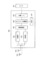
図1は、本実施形態に係る無線通信装置の一例を示すブロック図である。無線通信装置1は、干渉検出部10と、可変アンテナ部11と、制御部12と、記憶部14と、通信部15と、を備える。制御部12は、アンテナ切替部16と、通信制御部17とを備える。
(1st Embodiment)
FIG. 1 is a block diagram illustrating an example of the wireless communication device according to the present embodiment. The wireless communication device 1 includes an
無線通信装置1は、例えば、無線LANを構成するアクセスポイント(以下、基地局と呼ぶ場合もある)であり、電波等の無線媒体を用いて、相手の無線通信装置とフレームの送受信をする装置である。相手の無線通信装置は、アクセスポイントが形成するネットワーク(BSS:Basic Service Set)に属する無線通信端末である。以下、無線通信端末を、端末または通信端末またはSTA(ステーション)と呼ぶ場合もある。なお、アクセスポイント(基地局)は、中継機能等を有する点を除き、ステーションと同様の機能を有するため、無線通信端末の一形態である。非基地局の端末という場合はステーションを指すが、単に無線通信端末(端末)というときは、ステーションのみならず、アクセスポイントを指してもよい。 The wireless communication device 1 is, for example, an access point (hereinafter, sometimes referred to as a base station) configuring a wireless LAN, and a device that transmits and receives frames to and from a partner wireless communication device using a wireless medium such as radio waves. It is. The partner wireless communication device is a wireless communication terminal belonging to a network (BSS: Basic Service Set) formed by the access point. Hereinafter, the wireless communication terminal may be referred to as a terminal, a communication terminal, or an STA (station). Note that an access point (base station) is a form of a wireless communication terminal because it has the same functions as a station except that it has a relay function and the like. A terminal of a non-base station refers to a station, but a simply wireless communication terminal (terminal) may refer to an access point as well as a station.
本実施形態では、無線通信装置1は、アクセスポイントである場合を想定するが、無線通信装置1はアクセスポイトに限定されない。例えば、無線通信装置1は、端末でもよいし、無線LAN以外の無線通信装置でもよい。 In the present embodiment, it is assumed that the wireless communication device 1 is an access point, but the wireless communication device 1 is not limited to an access point. For example, the wireless communication device 1 may be a terminal or a wireless communication device other than a wireless LAN.
無線LAN以外の無線通信装置について説明する。無線LANでは、LBT(Listen before Talk)方式が採用されている。具体的に、CSMA/CA(Carrier Sense Multiple Access/Collision Avoidance)方式が用いられている。このCSMA/CA方式では、キャリアセンスにより無線媒体の状態を検査し、状態がアイドル状態であった場合に、無線媒体へのアクセス権を獲得して、フレーム送信を行う。本実施形態に係る無線通信装置は、このようなLBT方式を利用するシステムを構成する無線通信装置であれば、無線LAN以外の無線通信装置でもよい。LBT方式を利用する無線LAN以外のシステム例としては、LAA(Licensed Assisted Access using LTE(Long Term Evolution))がある。LAAは、ライセンス不要の周波数帯域を用いてLTE通信を行う方式である。 A wireless communication device other than the wireless LAN will be described. In a wireless LAN, an LBT (Listen Before Talk) system is adopted. Specifically, a CSMA / CA (Carrier Sense Multiple Access / Collision Aidance) system is used. In the CSMA / CA system, the state of a wireless medium is checked by carrier sense, and when the state is an idle state, an access right to the wireless medium is acquired and frame transmission is performed. The wireless communication device according to the present embodiment may be a wireless communication device other than the wireless LAN as long as it is a wireless communication device constituting such a system using the LBT method. An example of a system other than the wireless LAN using the LBT method is LAA (Licensed Assisted Accessing LTE (Long Term Evolution)). LAA is a method for performing LTE communication using a license-free frequency band.
可変アンテナ部11は、電波を送受信する1つまたは複数のアンテナを備える。可変アンテナ部11は、通信部15から供給される無線周波数の信号を電波として空間に放射する。また、可変アンテナ部11は、空間から受信した無線周波数の信号を、干渉検出部10および通信部15に出力する。
The
ここで、可変アンテナ部11は、複数の放射パターンを有し、アンテナ設定の切り替えにより、放射パターンを変更可能である。放射パターンはビームパターンとも呼ばれる。以下では、放射パターンに呼び方を統一する。放射パターンの例として、全方位性のパターン、特定の方向への指向性を有するパターンなどがある。これらのパターンの任意に組み合わせた(重ねた)パターンもあり得る。
Here, the
放射パターンを変更可能なアンテナの構造例について説明する。一例として、1つのアンテナが、複数のブランチを有し、各ブランチのインピーダンスまたは抵抗を制御することで、アンテナの指向性を制御する構成がある。例えばアンテナが4つのブランチを有する場合、4つのブランチのインピーダンスの設定パターンを複数用意し、当該設定パターンの切り換えで、アンテナの指向性を制御する。このようなアンテナをアクセスポイントが1つまたは複数備える。複数備える場合、各アンテナの指向性を合成することで、合成した放射パターンを生成してもよい。または、別の構成として、1つのアンテナ素子の周囲を4つの金属板で囲むことでアンテナを構成し、アンテナ素子から放射された電波を各金属板で反射させて送信する構成でもよい。この場合、各金属板の角度または位置を調整することで、アンテナの指向性を制御する。ここで記載した以外のアンテナ構造も可能である。 An example of the structure of the antenna whose radiation pattern can be changed will be described. As an example, there is a configuration in which one antenna has a plurality of branches, and the directivity of the antenna is controlled by controlling the impedance or resistance of each branch. For example, if the antenna has four branches, a plurality of impedance setting patterns for the four branches are prepared, and the directivity of the antenna is controlled by switching the setting patterns. The access point includes one or more such antennas. When a plurality of antennas are provided, a combined radiation pattern may be generated by combining the directivity of each antenna. Alternatively, as another configuration, an antenna may be configured by surrounding one antenna element with four metal plates, and a radio wave radiated from the antenna element may be reflected by each metal plate and transmitted. In this case, the directivity of the antenna is controlled by adjusting the angle or position of each metal plate. Antenna structures other than those described here are possible.
アンテナ切替部16は、可変アンテナ部11の設定を切り替えることにより、可変アンテナ部11の放射パターンを変更する。アンテナ切替部16は、通信制御部17からの指示に従って、放射パターンの変更を行う。
The
干渉検出部10は、可変アンテナ部11からの受信信号を解析することにより、無線通信装置1が使用している動作チャネルおよびその他のチャネルの干渉信号を検出する。干渉信号が検出される場合に、干渉信号の特徴を把握する。例えば動作チャネルにおける他の通信装置との干渉は、デューティ比の高い干渉かなどを特定する。動作チャネルとは、周波数領域に設定された複数の周波数チャネルのうち、通信に使用しているチャネルのことである。デューティ比は、一定期間内に受信した信号のうち、閾値以上のレベルの信号が受信された期間長の割合である。干渉検出部10の動作の詳細については、後述する。
The
通信制御部17は、無線通信装置1の通信に関する制御、可変アンテナ部11の放射パターンの制御、およびチャネルの切替制御等を行う。
The
通信制御部17は、通信に関する制御として、通信プロトコルの処理を行う。通信プロトコルの処理は、無線LANの場合、MAC層の処理を含む。具体的に、MACフレームの生成、受信したMACフレームの解析および解析結果に基づく処理等がある。MAC層より上位の層(TCP/IP、またはUDP/IP等)の処理を含んでもよい。なお、MACフレームの種類には、大別して、データフレーム、管理フレーム、制御フレームがあるが、どのフレームでもかまわない。なお、データフレームは、無線通信装置の内部で生成されたデータを他の装置に送信するフレームである。管理フレームは、他の端末との間の通信リンクの管理のために用いられるフレームであり、一例として、ビーコンフレーム、アソシエーション要求フレーム、アソシエーション応答フレーム等がある。制御フレームは、管理フレーム及びデータフレームを、他の無線通信装置との間で送受信(交換)するときの制御のために用いられるフレームであり、一例として、RTS(Request to Send)フレーム、CTS(Clear to Send)フレーム、ACKフレーム等がある。
The
また、通信制御部17は、放射パターンの制御として、動作チャネルに干渉がある場合に、干渉の状況に応じて、放射パターンの選択ポリシーを決定する。一例として、複数のポリシーの中からポリシーを選択する。通信制御部17は、選択したポリシーに従って、放射パターンの変更を行う。
In addition, as control of the radiation pattern, when there is interference in the operation channel, the
また、通信制御部17は、干渉の状況に応じて、動作チャネルの変更を決定する。動作チャネルを変更する場合、変更後のチャネルを指定したチャネル切替信号を送信する。より詳細には、変更後チャネルを指定したチャネル切り替え指示を含むフレームを生成し、当該フレームを送信する。フレームの具体例として、ビーコンフレームを用いてもよいし、これとは別の管理フレームを用いてもよい。フレームの送信は、CSMA/CAに従って手順で行う。動作チャネルの変更に伴い、通信部15における送信用のフィルタおよび受信用のフィルタの設定を変更する。
Further, the
記憶部14は、放射パターンとアンテナ設定情報とを対応づけた対応情報(あるいはテーブル情報)を保持している。放射パターンには予め識別子が与えられている。アンテナ設定情報は、対応する放射パターンを得るために必要なアンテナの設定を表す。例えば複数のアンテナのそれぞれが複数のブランチを有する場合、アンテナ設定情報は、複数のアンテナのそれぞれについて、各ブランチのインピーダンス値(または抵抗値)を表す値を含む。また、記憶部14は、放射パターンの指向性に関する情報(方向または角度等)を記憶してもよい。これらの情報は、製品の製造時または出荷時に設定されてもよいし、無線通信装置1がこれらの情報の設定指示を外部装置から受信することにより、記憶部14に設定してもよい。外部装置は、本無線通信装置1のユーザの装置でもよいし、サーバでもよい。
The
また、記憶部14は、無線通信装置1における放射パターンの使用履歴(以下、放射パターン履歴)を記憶する。一例として、放射パターン履歴は、各放射パターンの選択回数、送信成功率または通信品質等を、チャネルごとに分類して、記憶している。通信品質の例として、RSSI(Received Signal Strength Indicator)、SN(Singanl to Noise)比がある。通信品質は、平均値でも、最新値でもよい。放射パターン履歴は、各放射パターンが使用された時刻および順序に関する情報を、チャネルごとに分類して記憶してもよい。放射パターン履歴の更新は、通信制御部17またはアンテナ切替部16またはこれらの両方が行う。例えば通信制御部17は、通信を行うごとに、通信で使用した放射パターンと、現在のチャネルと、通信の結果とに基づき、放射パターン履歴を更新する。
Further, the
ここで、ポリシーの例を示す。例えば、記憶部14に記憶されている放射パターン履歴に基づいて放射パターンを選択するポリシー(履歴利用ポリシー)がある。また、可変アンテナ部11に設定可能な複数の放射パターンからランダムに放射パターンを選択するポリシー(ランダムポリシー)がある。また、指定された方向または特定の方向に指向性を有する放射パターンを選択するポリシー(指向性ポリシー)がある。また、全放射パターンを順番に切り換えて通信品質(SN比等)を測定し、最も高いまたは閾値以上の通信品質が得られた放射パターンを選択するポリシー(実測ポリシー)がある。なお、通信品質の測定は、通信制御部17または干渉検出部10で行えばよい。その他のポリシーの例として、予め定めた放射パターンを選択、または予め定めた優先順位で放射パターンを選択するポリシー(事前指定ポリシー)がある。予め定めた放射パターンは、例えば全方位放射パターンでもよいし、これ以外の放射パターンでもよい。
Here, an example of the policy is shown. For example, there is a policy (history use policy) for selecting a radiation pattern based on the radiation pattern history stored in the
各ポリシーはさらに細かく分類されてもよい。例えば履歴利用ポリシーにおいて、過去の選択回数に基づいて放射パターンを選択するポリシー(選択回数ポリシー)、通信の成功確率に基づいて放射パターンを選択するポリシー(成功率ポリシー)、通信品質に基づいて放射パターンを選択するポリシー(通信品質ポリシー)がある。このほか、放射パターン履歴に含まれていない放射パターンを選択するポリシーや、これらのポリシーを組み合わせたポリシーがある。選択回数ポリシーでは、選択回数が多いものから優先的に放射パターンを選択することがある。成功率ポリシーでは、成功確率が高いものから優先的に放射パターンを選択することや、成功確率が閾値以上もののから優先的に選択することなどがある。なお、履歴利用ポリシーを用いる場合において、放射パターンの履歴が空の場合や、該当する放射パターンが存在しない場合には、予め定められたデフォルトの放射パターンを選択してもよい。デフォルトの放射パターンとしては、例えば全方位放射パターンでもよいし、これ以外の放射パターンでもよい。ここで示したポリシー例は一例に過ぎず、他にも様々なポリシーを定義できる。 Each policy may be further categorized. For example, in the history usage policy, a policy of selecting a radiation pattern based on the number of past selections (selection number policy), a policy of selecting a radiation pattern based on the probability of successful communication (success rate policy), and a radiation based on communication quality There is a policy (communication quality policy) for selecting a pattern. In addition, there are policies that select radiation patterns that are not included in the radiation pattern history, and policies that combine these policies. In the selection frequency policy, a radiation pattern may be preferentially selected in descending order of selection frequency. In the success rate policy, the radiation pattern is preferentially selected from those having a high success probability, and the radiation pattern is preferentially selected from those having a success probability equal to or more than a threshold. When the history use policy is used, a predetermined default radiation pattern may be selected when the history of the radiation pattern is empty or when there is no corresponding radiation pattern. The default radiation pattern may be, for example, an omnidirectional radiation pattern or another radiation pattern. The policy example shown here is merely an example, and various other policies can be defined.
各ポリシーは記憶部14に格納されていてもよいし、通信制御部17に格納されていてもよい。各ポリシーはデータの形式で存在しても、プログラム(ロジック)の形式で存在してもよい。
Each policy may be stored in the
通信部15は、通信プロトコルのPHY層(物理層)に関する処理、および無線処理を行う。具体的には、PHY層の処理として、送信時におけるフレームへのPHYヘッダの付加、フレームの符号化、符号化されたデータの変調等がある。無線処理には、変調後の信号のDA(Digital to Analog)変換、送信フィルタによる帯域制御、アナログ信号のアップコンバートおよび増幅等の処理がある。受信時には、無線処理として、アンテナを介して受信した信号の低ノイズ増幅、増幅後の信号のダウンコンバート、受信フィルタによるダウンコンバート後の信号の帯域制御(動作チャネルの信号の抽出)等がある。なお、ダウンコンバートの前に、無線LANシステムの帯域制御(システムで使う全帯域の信号抽出)を行うフィルタ処理を行ってもよい。PHY層の処理として、帯域制御後の信号の復調および復号、および物理ヘッダの解析(除去)等の処理がある。
The
制御部12、干渉検出部10および通信部15の機能は、CPU等のプロセッサで動作するソフトウェア(プログラム)によって行われてもよいし、ハードウェアによって行われてもよいし、ソフトウェアとハードウェアの両方によって行われてもよい。ソフトウェアはROM、RAM等のメモリ、ハードディスク、SSDなどの記憶媒体に記憶してプロセッサにより読み出して実行してもよい。
The functions of the
記憶部14は、メモリでもよいし、SSD、ハードディスク等でもよい。メモリはSRAM、DRAM等の揮発性メモリでも、NAND、MRAM等の不揮発性メモリでもよい。記憶部14は、図1では独立したブロックとして示されているが、アンテナ切替部16または通信制御部17内に存在しても良いし、アンテナ切替部16および通信制御部17に分散して配置されてもよい
The
図2は、干渉検出部10の構成例を示すブロック図である。干渉検出部10は、信号検出部100と、信号認識部110とを備える。
FIG. 2 is a block diagram illustrating a configuration example of the
信号検出部100は、可変アンテナ部11から受信信号が入力され、受信信号を解析することで、時間と周波数との関係のデータ(時間周波数データ)を生成する。時間周波数データは、例えば、受信信号のAD変換、およびFFT(Fast Fourier Transform)処理を行うことで生成できる。これ以外の方法で、時間周波数データを生成してもよい。図3は、時間周波数データの一例を示す。この例では、時間周波数データに、4つの波形が含まれている。
The
波形51は、低周波数帯側で、1MHz幅の電波が連続的に受信されたことを示している。これはアナログビデオ、アナログコードレス電話、ジャマー(JAMMER)などのアナログ機器の出力に見られるパターン(以下、連続波パターンと呼ぶことがある)である。波形52は、時間の進行に応じて周波数が一定の傾きで変化することを周期的に繰り返すパターンであり、レーダー等に見られるパターンである。波形53は、一定の周波数帯域内で短いパルス状の信号がランダムに出現しており、周波数ホッピングを行うブルートゥース(登録商標)等の機器に見られるパターンである。波形54は、一定の周波数帯域を占める信号が間欠的に出現しており、IEEE802.11に準拠する無線LANなどの無線通信装置に見られるパターンである。
The
信号認識部110は、信号検出部100により生成された時間周波数データを受け取り、時間周波数データを分析することで、分析対象となる周波数範囲内に存在する干渉信号の特徴を把握する。ここでは、干渉信号の特徴として、干渉信号の発生源(干渉源)となる装置の種別を把握する。このために、信号認識部110は、分類器111と、データベース112を備える。なお、分析は、分析対象となる周波数範囲全体に対して行ってもよいし、周波数範囲をチャネルごとの帯域に分割し、分割した帯域(チャネル)ごとに分析を行ってもよい。
The
分類器111は、時間周波数データに基づき複数の特徴量を計算する。特徴量の例として、スペクトル形状の特徴量、信号がハイレベル(閾値以上のレベル)となる時間の割合を示す値または範囲、パルス形状の特徴量、パルスの拡散度などがある。これらの特徴量は一例に過ぎず、装置の種別を判定するのに有効な様々な特徴量を定義してもよい。図4(A)には特徴量の種類を模式的に示す。分類器111は、複数の特徴量に基づき、干渉源となる装置の種別を特定する。装置の種別として、一例として、アナログ機器(アナログビデオ、アナログコードレス電話、JAMMERなど)、ブルートゥース機器、無線LAN装置(Wifi装置)、レーダー装置などの分類が考えられる。分類器111は、これらのいずれかの分類を、干渉源の装置の種別として決定する。このような分類の処理は、任意のモデルを用いて行うことができる。モデルの例として2分木を用いることができる。2分木の例を図4(B)に模式的に示す。 The classifier 111 calculates a plurality of feature values based on the time-frequency data. Examples of the feature amount include a spectrum shape feature amount, a value or a range indicating a ratio of time when a signal is at a high level (a level equal to or higher than a threshold), a pulse shape feature amount, and a pulse diffusion degree. These feature values are merely examples, and various feature values effective for determining the type of the device may be defined. FIG. 4A schematically shows the types of feature amounts. The classifier 111 specifies the type of the device serving as the interference source based on the plurality of feature amounts. As a type of the device, for example, a classification of an analog device (analog video, analog cordless telephone, JAMMER, etc.), a Bluetooth device, a wireless LAN device (WiFi device), a radar device, and the like can be considered. The classifier 111 determines any of these classifications as the type of the interference source device. Such a classification process can be performed using an arbitrary model. A binary tree can be used as an example of the model. An example of a binary tree is schematically shown in FIG.
図4(B)の2分木は、最上位ノード1,最下層ノード2、4、5、これら以外の中間ノード3を備える。最下層ノード以外のノード1、3には、それぞれ1つまたは複数の特徴量を用いた処理が割り当てられる。最上位ノード1から処理を開始し、処理結果に応じて、いずれかの下位ノード(子ノード)に分岐する。これを最下層ノードに達するまで繰り返す。最下層ノード2、ノード4、ノード5には、判定結果となる装置種別が割り当てられている。例えばノード2にはアナログ機器、ノード4にはWifi装置、ノード5にはレーダー装置が割り当てられる。到達した最下層ノードに割り当てられた装置種別が、干渉源の装置の種別として決定される。
The binary tree in FIG. 4B includes a top node 1, a
ノードでの処理の一例として、1つまたは特徴量を用いた演算が行われ、演算の結果に応じて、複数の子ノードのいずれかに進む。例えば特徴量または特徴量に基づき演算される値が、第1値より大きいかを判断し、第1値より大きい場合は第1子ノード、第1値以下の場合は第2子ノードに分岐するなどである。なお、子ノードの個数は、図4(B)では2であるが、3以上でもよい。データベース112には、2分木のデータ、特徴量の計算式などが格納されている。
As an example of processing at a node, an operation using one or a feature amount is performed, and the process proceeds to any of a plurality of child nodes according to the result of the operation. For example, it is determined whether the feature value or the value calculated based on the feature value is greater than the first value. If the value is greater than the first value, the process branches to a first child node. If the value is less than the first value, the process branches to a second child node. And so on. The number of child nodes is 2 in FIG. 4B, but may be 3 or more. The
このような2分木は、機械学習により生成すればよい。例えば、予め装置種別が分かっている1つ以上の装置から信号を受信し、受信した信号から複数の特徴量を計算して、計算した複数の特徴量を装置種別に対応づけて蓄積しておく。複数の種別の装置について取得したこれらのデータを機械学習することで、複数の特徴量から、装置種別を特定するモデルを生成できる。 Such a binary tree may be generated by machine learning. For example, a signal is received from one or more devices whose device type is known in advance, a plurality of feature values are calculated from the received signal, and the calculated plurality of feature values are stored in association with the device type. . By performing machine learning on these data acquired for a plurality of types of devices, a model for specifying the type of device can be generated from a plurality of feature amounts.
使用するモデルは、2分木に限定されず、ニューラルネットワークなど他のモデルでもよい。 The model used is not limited to the binary tree, and may be another model such as a neural network.
ここでは干渉信号の特徴を把握する方法として、装置の種別を特定する例を示した。別の方法として、複数の波形パターンをテンプレートとして用意しておき、干渉信号が、どの波形パターンを有するかを特定してもよい。例えば、受信信号を解析して得た波形データと、各テンプレートとの類似度を計算し、最も高い類似度の波形パターンを特定してもよい。類似度の計算前に、波形データを正規化してもよい。波形同士の類似度の計算は、一般的な波形同士の距離を計算するアルゴリズムなどを用い、計算された距離に応じて、類似度を求めればよい。一例として、距離が小さいほど、大きな値となるように類似度を定義してもよい。なお、分析は、周波数範囲をチャネルごとの帯域に分割し、分割した帯域(チャネル)ごとに分析を行ってもよい。 Here, as an example of a method for grasping the characteristics of the interference signal, an example in which the type of the device is specified has been described. As another method, a plurality of waveform patterns may be prepared as templates, and which waveform pattern the interference signal has may be specified. For example, the similarity between each template and the waveform data obtained by analyzing the received signal may be calculated, and the waveform pattern having the highest similarity may be specified. Before calculating the similarity, the waveform data may be normalized. The calculation of the similarity between waveforms may be performed by using a general algorithm for calculating the distance between waveforms or the like, and calculating the similarity according to the calculated distance. As an example, the similarity may be defined such that the smaller the distance, the larger the value. In the analysis, the frequency range may be divided into bands for each channel, and the analysis may be performed for each divided band (channel).
次に、本実施形態に係る無線通信装置1のチャネル切替処理について説明する。図5および図6は、無線通信装置1のチャネル切替処理のフローチャートである。以下の説明において、無線通信装置1は、動作チャネルとして、チャネルAを使用している状況を想定する。 Next, a channel switching process of the wireless communication device 1 according to the present embodiment will be described. FIG. 5 and FIG. 6 are flowcharts of the channel switching process of the wireless communication device 1. In the following description, it is assumed that wireless communication device 1 uses channel A as an operation channel.
図5に示すように、通信制御部17は、予め決定したポリシーに従って、放射パターンを選択し、選択した放射パターンの設定をアンテナ切替部16に指示する。アンテナ切替部16は、当該放射パターンに応じた構成に、可変アンテナ部11を設定する(ステップS10)。本ステップS10では、履歴利用ポリシーを用いる場合を想定する。
As shown in FIG. 5, the
アンテナ切替部16により放射パターンが設定されたら、通信制御部17は、チャネルAを用いて、通信部15を介して、通信を行う(ステップS11)。通信制御部17は、新規にフレームを送信する場合には、CSMA/CAに従って、無線媒体へのアクセス権を獲得した上で、フレーム送信を行う。具体的に、キャリアセンスにより無線媒体の状態を検査し、状態がアイドルであった場合に、アクセス権を獲得して、フレーム送信を行う。また、通信相手の端末から、送達確認応答を必要とするフレームを受信した場合は、フレームの受信完了から一定時間後に、送達確認応答フレーム(ACKフレーム等)を送信する。
When the radiation pattern is set by the
干渉検出部10は、可変アンテナ部11を介して受信した信号に基づき、チャネルAで他の通信装置との電波干渉が発生しているかを検出する(ステップS12)。例えば、一定時間、無線媒体を監視し、その間に、自装置が形成するネットワーク以外の装置からの、閾値以上のレベルの信号(無線媒体がビジー状態と判断されるレベルの信号)が検出された場合は、電波干渉が発生していると判断する。検出の動作は、通信制御部17の通信とは独立して(並行して)行われている。なお、自装置のネットワークに属する装置からの信号か否かは、例えばフレームまたはそのヘッダを解析することで分かる。この解析は干渉検出部10で行ってもよいし、通信制御部17で行って、解析の結果を干渉検出部10に通知してもよい。
The
干渉検出部10が、干渉の発生を検出しなかった場合(ステップS12:No)、通信制御部17は、現在の放射パターンを維持して、チャネルAで通信を継続する(ステップS13)。
When the
一方で、チャネルAにおける干渉の発生を検出した場合(ステップS12:Yes)、干渉検出部10は、チャネルAにおける干渉信号の特徴を特定する(ステップS20)。具体的に、干渉源の装置種別、例えば無線LAN装置(WiFi装置)、アナログ機器(アナログコードレス電話、アナログビデオ)等、ブルートゥース装置、レーダー装置といった装置種別を特定する。または、別の方法として、前述したように波形パターンを特定してもよい。以下では装置種別を特定する場合を想定する。なお、特定する装置種別数は1つの場合のみならず、複数の場合もありうる。また、干渉源の方向または位置またはこれらの両方を推定可能な場合は、これらを特定してもよい。干渉源の方向または位置の推定には、一般的な到来方向推定アルゴリズムまたは位置推定アルゴリズムを用いればよい。このとき、到来方向および位置の推定処理は、干渉検出部10が行ってもよいし、通信制御部17が行ってもよい。
On the other hand, when the occurrence of the interference in the channel A is detected (Step S12: Yes), the
次に、干渉検出部10は、干渉源の信号のデューティ比が高いか否かを判定する(ステップS21)。デューティ比は、一定期間内に受信した信号のうち、閾値以上のレベルの信号が受信された期間長の割合である。デューティ比が高いとは、デューティ比が一定値以上のことを意味する。
Next, the
デューティ比が高い装置として予め定めた種別の装置が検出された場合は、干渉源の信号のデューティ比が高いと判定する。ここではアナログ機器(アナログコードレス電話、アナログビデオ)がそのような装置に相当する。アナログ機器は、つまり、高デューティ比装置の一例である。なお、ステップS20で波形パターンを特定する場合は、予め定めたパターンの波形、例えば図3の波形51のような連続波パターンが検出された場合は、干渉源の信号のデューティ比が高いと判定する。
When a device of a predetermined type is detected as a device having a high duty ratio, it is determined that the duty ratio of the signal of the interference source is high. Here, analog devices (analog cordless telephones, analog video) correspond to such devices. An analog device is an example of a high duty ratio device. In the case where the waveform pattern is specified in step S20, if the waveform of the predetermined pattern, for example, a continuous wave pattern such as the
デューティ比が高くないと判定された場合(ステップS21:No)、干渉検出部10は、チャネルAで干渉が検出されたが、デューティ比の高い干渉ではないことを表す情報を、通信制御部17に送る。通信制御部17は、この情報を受けると、現在のチャネルAの使用を継続することを決定しつつ、放射パターンの変更することを決定する。通信制御部17は、チャネルAに関して、現在のポリシー(履歴利用ポリシー)に基づき、放射パターンの選択をし直す。通信制御部17は、選択した放射パターンへの変更指示信号を、アンテナ切替部16に出力する。アンテナ切替部16は、指示された放射パターンに応じて、可変アンテナ部11を設定する(ステップS22)。
When it is determined that the duty ratio is not high (step S21: No), the
例えば、通信品質(SN比等)の平均が最も高い放射パターン、または通信成功率が最も高い放射パターンなどを特定する。特定されたパターンが、現在使用している放射パターンと同じパターンになる場合は、現在の放射パターンを維持しても良いし、次に値が高い放射パターンを選択し直してもよい。放射パターン履歴を利用した別の選択例として、過去において現在使用している放射パターンと同じ放射パターンを使ったデータを特定し、特定した放射パターンの切り替え後の通信成功率またはSN比が一定値以上の場合は、その特定したパターンと同じ放射パターンを選択することなども可能である。 For example, a radiation pattern having the highest communication quality (SN ratio or the like) or a radiation pattern having the highest communication success rate is specified. If the specified pattern is the same as the currently used radiation pattern, the current radiation pattern may be maintained, or the radiation pattern with the next highest value may be selected again. As another selection example using the radiation pattern history, data using the same radiation pattern as the currently used radiation pattern in the past is specified, and the communication success rate or SN ratio after switching the specified radiation pattern is constant. In the above case, it is also possible to select the same radiation pattern as the specified pattern.
可変アンテナ部11の放射パターンを変更した後、通信制御部17は、通信部15を介して、チャネルAで通信を行う(ステップS23)。通信制御部17またはアンテナ切替部16またはこれらの両方は、変更後の放射パターンと、通信の結果(成功または失敗したか等)に基づき、放射パターン履歴を更新する。
After changing the radiation pattern of the
図7は、無線通信装置1の動作チャネルAが、他の通信装置2の出力する電波と干渉している状況を示している。この例では、アクセスポイントに相当する無線通信装置1と、端末3A、3B、3C、3Dとで構成される無線LANシステムの近くに、別のシステムの他の通信装置2が存在する。無線通信装置1は全方位性の放射パターンを用いているとする。他の通信装置2は、デューティ比の高くない信号を出力する装置であるとする。ここでは、隣接するアクセスポイントまたはそれに属する端末を想定する。円状の点線8は、他の通信装置2から出力される電波の範囲を示す。無線通信装置1はこの範囲内に存在しており、チャネルAの干渉を検知する。
FIG. 7 shows a situation in which the operation channel A of the wireless communication device 1 is interfering with radio waves output from another
図8は、図7の状況において、ステップS21で他の通信装置2が、デューティ比の高い干渉源ではないと判断され、かつステップS22で、放射パターンが変更された後の無線通信装置1の放射パターンを示す図である。図中の実線31は、無線通信装置1の放射パターンを表す。この放射パターンの領域内には、端末3A、3Bが含まれ、端末3C、3Dおよび他の通信装置2は含まれない。無線通信装置1は、他の通信装置2の電波を受信しない(他の通信装置2からの受信信号を検知しない)ため、チャネルAを継続して利用しつつ、端末3Aおよび3Bと通信を行うことができる。ただし、端末3C、3Dと通信を行うことはできない。
FIG. 8 shows that, in the situation of FIG. 7, the
一方で、干渉検出部10が、デューティ比の高い干渉源が存在すると判定した場合(ステップS21:Yes)、干渉検出部10は、チャネルAで干渉が検出され、かつそれがデューティ比の高い干渉であることを通知する情報を、通信制御部17に送る。
On the other hand, when the
通信制御部17は、この情報を受けると、チャネルA以外の1つまたは複数の候補チャネルの電波受信状況を調べることにより、空きチャネルが存在するかを判断する(ステップS30)。空きチャネルが存在するかの判断は、任意の方法を用いて行えばよい。例えば一定時間、候補チャネルを監視し、一定レベル以上の信号が受信されなければ、当該候補チャネルは空きチャネルである判断してもよい。なお、空きチャネルの存在有無の検査は、干渉検出部10が行ってもよい。この場合、通信制御部17は、空きチャネルが存在するかの決定を行うことを指示する指示信号を干渉検出部10に出力し、干渉検出部10が空きチャネルの存在有無を決定し、通信制御部17にその結果をフィードバックする。
Upon receiving this information, the
通信制御部17は、チャネルA以外の候補チャネルの中に、空きチャネルがあると判断した場合(ステップS30:Yes)、当該検出した空きチャネルを、チャネルAの変更先のチャネル(以下、チャネルBと呼ぶ)として決定する。空きチャネルは、最も早く検出された空きチャネルでもよいし、複数の空きチャネルを検出した場合は、最も通信品質が高いチャネルでもよい。
If the
通信制御部17は、ポリシーをランダムポリシーに切り替え、ランダムポリシーに従って、ランダムに放射パターンを選択、すなわち任意の放射パターンを選択する。通信制御部17は、アンテナ切替部16を介して、可変アンテナ部11に、選択した放射パターンを設定する(ステップS40)。つまり、どの放射パターンを選択すれば、干渉源の影響を回避して、無線媒体へのアクセス権をとれるか不明なため、ランダムに放射パターンを選択する。
The
通信制御部17は、可変アンテナ部11の放射パターンが変更された後、動作チャネルを変更する前に、チャネルAを介して、チャネル切替信号を送信する(ステップS41)。より詳細には、チャネルBへのチャネル切り替えを指示する情報を含むフレームを生成し、当該フレームを送信する。チャネル切り替えを指示するフレームの例として、ビーコンフレームを用いてもよいし、これとは別の管理フレームを用いてもよい。フレームの送信は、CSMA/CAに従って手順で行う。すなわち、無線媒体のキャリアセンスを行い、キャリアセンスの結果がアイドル状態を示す場合、無線媒体へのアクセス権を獲得し、フレームを送信する。チャネル状態がビジー状態であるために、一定期間経過してもアクセス権の獲得が出来ない場合は、ステップS40に戻って、ランダムポリシーの下、放射パターンを再度選択し直してもよい。送信するフレームには、チャネル切り替えを行うタイミングを示す情報を設定してもよい。チャネル切り替えタイミングの情報は、別のフレームによって送信してもよい。
After the radiation pattern of the
通信制御部17は、予め定めた切り替えタイミングで、動作チャネルをチャネルAからチャネルBに切り替え、以降は、チャネルBで通信を行う(ステップS42)。チャネルBで通信を開始する際に用いるポリシーは、事前指定ポリシー(予め定めた放射パターンを選択または予め定めた順番で放射パターンを選択)でもよいし、引き続きランダムポリシーを用いてもよいし、その他のポリシーを用いてもよい。チャネルBの放射パターン履歴がある場合は、履歴利用ポリシーを用いてもよい。
The
通信制御部17は、ステップS40、S41を複数回繰り返した後で、動作チャネルをチャネルBへ切り替えてもよい。これにより多くの放射パターンで、チャネル切替信号を送信する可能性を高め、出来るだけ多くの端末に、チャネル切り替えを通知できる可能性が高くなる。ただし、回数が多いと、それだけ実際にチャネル変更するまでの時間が長くなるため、高速なチャネル変更が困難となる。従って、チャネル変更までに許容される時間長に応じて、ステップS40、S41を繰り返す回数を制限してもよい。
The
図9は、ステップS40、S41の具体例を説明する図である。無線通信装置1の動作チャネルAが、他の通信装置2の出力する電波と干渉している。この例では、アクセスポイントに相当する無線通信装置1と、端末3A、3B、3C、3Dとで構成される無線LANシステムの近くに、別のシステムの他の通信装置7が存在する。無線通信装置1は全方位性の放射パターンを用いているとする。他の通信装置7は、デューティ比の高い装置、例えばアナログビデオカメラ等のアナログ機器であるとする。円状の点線9は、他の通信装置2から出力される電波の範囲を示す。無線通信装置1はこの範囲内に存在しており、チャネルAの干渉を検知する。
FIG. 9 is a diagram illustrating a specific example of steps S40 and S41. The operation channel A of the wireless communication device 1 is interfering with a radio wave output from another
無線通信装置1が、ステップS40で放射パターンを変更した結果、図中の実線43で示す放射パターンになっている。無線通信装置1は、この放射パターンで、チャネルAを介して、チャネル切替信号を送信する。端末3A、3Bは、放射パターンの範囲に含まれ、かつ他の通信装置7の電波範囲に含まれないことから、チャネル切替信号の受信に成功する。端末3Cでは、他の通信装置7の電波範囲に含まれるため、チャネル切替信号の受信に成功するかは、端末3Cの指向性にも依存する。ここでは、端末3Cはチャネル切替信号の受信に成功しなかった場合を想定する。端末3Dは、無線通信装置1の放射パターンに含まれないため、チャネル切替信号を受信しない。チャネル切替信号の受信に成功した端末3Aおよび端末3Bは、例えば、無線通信装置1が指定した空きチャネルであるチャネルBへ、予め指定されたタイミングで、動作チャネルを切り替える。図10は、無線通信装置1、端末3Aおよび端末3Bが、動作チャネルを、チャネルAからチャネルBへと切り替えた様子を示す図である。図10において、無線通信装置1、端末3Aおよび端末3Bが破線の矩形で囲まれているが、これはこれらの動作チャネルがチャネルBに切り替えられたことを意味する。なお、端末3Cと、端末3Dでは、依然としてチャネルAが設定されている。
As a result of changing the radiation pattern in step S40, the wireless communication device 1 has a radiation pattern indicated by a solid line 43 in the drawing. The wireless communication device 1 transmits a channel switching signal via the channel A with this radiation pattern. Since the
図11は、チャネルAで無線通信装置1と通信できなくなったことを検知した端末3Cおよび端末3Dがチャネルサーチにより、無線通信装置1の動作チャネルであるチャネルBを特定して、動作チャネルをチャネルBに切り換えた様子を示している。端末3Cおよび端末3Dは、チャネルBで無線通信装置1とアソシエーションプロセスを再度実行して、無線通信装置1が形成するネットワークに所属する。端末3Cおよび端末3Dの動作チャネルがチャネルBへ切り換えられたため、図11では、端末3Cおよび端末3Dが、破線の矩形で囲まれている。無線通信装置1、端末3A〜3Dは、他の通信装置7と干渉することなく通信を行うことができる。
FIG. 11 shows that the
一方、通信制御部17は、チャネルA以外の候補チャネルの中に、空きチャネルが存在しないと判断した場合(ステップS30:No)、記憶部14に記憶されている放射パターン履歴をリセットする。また通信制御部17は、使用するポリシーをランダムポリシーに切り替え、ランダムポリシーに従って任意の放射パターンを選択する。選択した放射パターンへの変更をアンテナ切替部16に指示し、アンテナ切替部16は、可変アンテナ部11に、指示された放射パターンを設定する(ステップS31)。通信制御部17は、チャネルAで通信を行う(S32)。今回設定された放射パターンや通信の結果等を放射パターン履歴に登録する(ステップS33)。これにより放射パターン履歴を更新する。
On the other hand, if the
なお、図5のステップS22では、履歴利用ポリシーを引き続き利用して放射パターンを選択したが、別のポリシーに変更してもよい。例えばステップS12で干渉が発生したと判定された回数が一定時間内に所定値に達した場合は、ポリシーを変更してもよい。 In step S22 in FIG. 5, the radiation pattern is selected by continuously using the history use policy, but may be changed to another policy. For example, when the number of times that it is determined that the interference has occurred in step S12 reaches a predetermined value within a predetermined time, the policy may be changed.
上述した処理の変形例を示す。
(第1の変形例)
図12は、第1の変形例に係るフローチャートである。図5のステップS20がステップS51に代わっている。図5のステップS20では装置種別を特定したが、本フローのステップS51では、デューティ値を計算する。具体的には、所定期間内に受信した信号のうち、閾値以上のレベルの信号が受信された期間長を計算する。そして、所定期間の長さに対する、当該計算した期間長の比率を計算する。これにより、デューティ比を得る。続くステップS21では、デューティ比が一定値以上かを判断し、一定値以上であれば、デューティ比の高い干渉が存在したと判定し、ステップS30に進む。デューティ比が一定値未満であれば、デューティ比の高い干渉が存在しなかったと判定し、ステップS22に進む。ステップS30、S22以外のステップの処理は、これまで述べたのと同様の処理でよい。
A modified example of the above-described processing will be described.
(First Modification)
FIG. 12 is a flowchart according to the first modification. Step S20 in FIG. 5 replaces step S51. Although the device type is specified in step S20 of FIG. 5, the duty value is calculated in step S51 of this flow. Specifically, of the signals received within a predetermined period, the length of a period during which a signal having a level equal to or higher than a threshold is received is calculated. Then, the ratio of the calculated period length to the length of the predetermined period is calculated. Thereby, a duty ratio is obtained. In a succeeding step S21, it is determined whether the duty ratio is equal to or more than a predetermined value. If the duty ratio is equal to or more than the predetermined value, it is determined that there is interference having a high duty ratio, and the process proceeds to step S30. If the duty ratio is less than the predetermined value, it is determined that there is no interference with a high duty ratio, and the process proceeds to step S22. The processing of steps other than steps S30 and S22 may be the same processing as described above.
(第2の変形例)
図6のステップS40でポリシーを変更(ランダム選択に変更)する際、キャリアセンスで用いる受信判定の閾値(例えば(CCA(Clear Channel Assessment)閾値))を高くしてもよい。一例として、第1閾値を、第1閾値より大きい第2閾値に変更する。
(Second Modification)
When the policy is changed (changed to random selection) in step S40 in FIG. 6, a threshold for reception determination (for example, (CCA (Clear Channel Assessment) threshold) used in carrier sense) may be increased. As an example, the first threshold is changed to a second threshold larger than the first threshold.
例えば通信部15は、第1閾値以上のレベルの信号を受信すると、信号受信を検知し、第1閾値未満のレベルの信号を受信しても信号受信を検知しないとする。つまり、第1閾値以上のレベルの信号では、無線媒体がビジー状態と判定し、第1閾値未満のレベルの信号では無線媒体はアイドル状態であると判定する。ステップS40で第1閾値を第2閾値に上げることで、第1閾値以上のレベルの信号を受信しても、信号のレベルが第2閾値未満であれば、無線媒体はアイドル状態と判断される。よってキャリアセンス中に他の通信装置2から信号を受信しても、信号のレベルが第2閾値未満であれば、無線媒体がアイドルと判定され、チャネル切替信号を送信できる。なお、図6のステップS31、図5のステップS22、またはこれらの両方でも、放射パターンを変更する際、受信判定の閾値を上げるようにしてもよい。
For example, it is assumed that the
ここでは、ポリシーを変更するとともに、閾値を上げたが、ポリシーを変更することなく、閾値を上げてもよい。この場合のフローチャートを図13に示す。図5のステップS40が、ステップS52に代わっている。ステップS52では、現在の放射パターンを維持しつつ、受信判定の閾値を高くする。一例として、第1閾値を、第1閾値より大きい第2閾値に変更する。なお、ステップS31、図5のステップS22、またはこれらの両方に対しても同様に、放射パターンを変更することなく、受信判定の閾値を上げるようにしてもよい。 Here, the policy is changed and the threshold is raised, but the threshold may be raised without changing the policy. FIG. 13 shows a flowchart in this case. Step S40 in FIG. 5 replaces step S52. In step S52, the threshold value for the reception determination is increased while maintaining the current radiation pattern. As an example, the first threshold is changed to a second threshold larger than the first threshold. Note that the threshold value of the reception determination may be increased without changing the radiation pattern in step S31, step S22 in FIG. 5, or both of them.
(第3の変形例)
これまでの説明では、高デューティの信号を出力する装置が、ビデオカメラ等のアナログ機器である場合を想定したが、その装置が、無線LAN以外のLBT方式を採用する通信装置である可能性もあり得る。その可能性がある場合には、ポリシーとしてランダムポリシーではなく、指向性ポリシー(指定された方向または特定の方向に指向性を有する放射パターンを選択する)を選択し、その通信装置に指向性を向けるような放射パターンを、ステップS40で設定してもよい。その通信装置に指向性を向けることで、無線通信装置1が送信した信号を、その通信装置が検知することができる。信号を検知した通信装置は、送信禁止期間(無線LANの場合、NAV(Network Allocation Vector)と呼ばれる)を設定し、フレーム送信を控えることが期待できる。ただし、キャリアセンスで一定期間以内にアクセス権を獲得出来ない場合は、ランダムポリシーに戻すなどしてもよい。ステップS40では、上述したランダムポリシーおよび指向性ポリシー以外のポリシーを選択することも可能である。
(Third Modification)
In the above description, it is assumed that the device that outputs a high-duty signal is an analog device such as a video camera. However, the device may be a communication device that employs the LBT method other than the wireless LAN. possible. If there is a possibility that this is the case, a directivity policy (selecting a radiation pattern having directivity in a specified direction or a specific direction) is selected instead of a random policy as a policy, and the directivity is given to the communication device. A radiation pattern to be directed may be set in step S40. By directing the directivity to the communication device, the communication device can detect the signal transmitted by the wireless communication device 1. The communication device that has detected the signal can be expected to set a transmission prohibition period (called a NAV (Network Allocation Vector) in the case of a wireless LAN) and refrain from transmitting a frame. However, if the access right cannot be acquired within a certain period by carrier sense, the access right may be returned to a random policy. In step S40, it is also possible to select a policy other than the above-mentioned random policy and directivity policy.
以上のように、本実施形態によれば、無線通信装置1は、デューティ比が高い他の通信装置が存在する場合に、ポリシーを変更することで、他の通信装置との干渉を防止可能な放射パターンを高速に選択できる。一例として、履歴利用ポリシーからランダムポリシーに変更することで、干渉を回避できる放射パターンを高速に選択できる。このようにして選択した放射パターンで、チャネル切替信号を送信することで、チャネル変更を高速に通知できる。チャネル切替信号を受信した端末は、切り替え後のチャネルで再度無線通信装置1とアソシエーションプロセスを行うことなく、チャネル切り替えを行うことができる。チャネル切替信号を受信できなかった端末(変更後の放射パターンの範囲に含まれない端末)は、チャネルサーチにより無線通信装置1を探索し、アソシエーションプロセスを行う必要があるが、チャネル変更後も引き続き無線通信装置1との通信を行うことができる。 As described above, according to the present embodiment, when another communication device having a high duty ratio exists, the wireless communication device 1 can prevent interference with another communication device by changing the policy. The radiation pattern can be selected at high speed. As an example, by changing the history use policy to the random policy, a radiation pattern that can avoid interference can be selected at high speed. By transmitting a channel switching signal with the radiation pattern selected in this way, a channel change can be notified at high speed. The terminal that has received the channel switching signal can perform channel switching without performing the association process again with the wireless communication device 1 on the channel after switching. A terminal that cannot receive the channel switching signal (a terminal not included in the range of the changed radiation pattern) needs to search for the wireless communication device 1 by a channel search and perform an association process. Communication with the wireless communication device 1 can be performed.
(第2の実施形態)
図14は、第2の実施形態に係る基地局(アクセスポイント)400の機能ブロック図である。このアクセスポイントは、通信処理部401と、送信部402と、受信部403と、アンテナ42A、42B、42C、42Dと、ネットワーク処理部404と、有線I/F405と、メモリ406とを備えている。アクセスポイント400は、有線I/F405を介して、サーバ407と接続されている。通信処理部401は、第1の実施形態で説明した制御部12および干渉検出部10と同様な機能を有している。送信部402および受信部403は、第1の実施形態で説明した通信部15と同様な機能を有している。ネットワーク処理部404は、第1の実施形態で説明した上位処理部と同様な機能を有している。ここで、通信処理部401は、ネットワーク処理部404との間でデータを受け渡しするためのバッファを内部に保有してもよい。このバッファは、DRAM等の揮発性メモリでもよいし、NAND、MRAM等の不揮発メモリでもよい。
(Second embodiment)
FIG. 14 is a functional block diagram of a base station (access point) 400 according to the second embodiment. This access point includes a
ネットワーク処理部404は、通信処理部401とのデータ交換、メモリ406とのデータ書き込み・読み出し、および、有線I/F405を介したサーバ407との通信を制御する。ネットワーク処理部404は、TCP/IPやUDP/IPなど、MAC層の上位の通信処理やアプリケーション層の処理を行ってもよい。ネットワーク処理部の動作は、CPU等のプロセッサによるソフトウェア(プログラム)の処理によって行われてもよいし、ハードウェアによって行われてもよいし、ソフトウェアとハードウェアの両方によって行われてもよい。
The
一例として、通信処理部401は、ベースバンド集積回路に対応し、送信部402と受信部403は、フレームを送受信するRF集積回路に対応する。通信処理部401とネットワーク処理部404とが1つの集積回路(1チップ)で構成されてもよい。送信部402および受信部403のデジタル領域の処理を行う部分とアナログ領域の処理を行う部分とが異なるチップで構成されてもよい。また、通信処理部401が、TCP/IPやUDP/IPなど、MAC層の上位の通信処理を実行するようにしてもよい。また、アンテナの個数はここでは4つであるが、少なくとも1つのアンテナを備えていればよい。
As an example, the
メモリ406は、サーバ407から受信したデータや、受信部403で受信したデータの保存等を行う。メモリ406は、例えば、DRAM等の揮発性メモリでもよいし、NAND、MRAM等の不揮発メモリでもよい。また、SSDやHDD、SDカード、eMMC等であってもよい。メモリ406が、基地局400の外部にあってもよい。
The
有線I/F405は、サーバ407とのデータの送受信を行う。本実施形態では、サーバ407との通信を有線で行っているが、サーバ407との通信を無線で実行するようにしてもよい。この場合、無線I/Fが、有線I/F405の代わりに用いればよい。
The wired I /
サーバ407は、データの送信を要求するデータ転送要求を受けて、要求されたデータを含む応答を返す通信装置であり、例えばHTTPサーバ(Webサーバ)、FTPサーバ等が想定される。ただし、要求されたデータを返す機能を備えている限り、これに限定されるものではない。PCやスマートフォン等のユーザが操作する通信装置でもよい。また、基地局400と無線で通信してもよい。
The
基地局400のBSSに属するSTAが、サーバ407に対するデータの転送要求を発行した場合、このデータ転送要求に関するパケットが、基地局400に送信される。基地局400は、アンテナ42A〜42Dを介してこのパケットを受信し、受信部403で物理層の処理等を、通信処理部401でMAC層の処理等を実行する。
When a STA belonging to the BSS of the
ネットワーク処理部404は、通信処理部401から受信したパケットの解析を行う。具体的には、宛先IPアドレス、宛先ポート番号等を確認する。パケットのデータがHTTP GETリクエストのようなデータ転送要求である場合、ネットワーク処理部404は、このデータ転送要求で要求されたデータ(例えば、HTTP GETリクエストで要求されたURLに存在するデータ)が、メモリ406にキャッシュ(記憶)されているかを確認する。メモリ406には、URL(またはその縮小表現、例えばハッシュ値や、代替となる識別子)とデータとを対応づけたテーブルが記憶されている。ここで、データがメモリ406にキャッシュされていることを、メモリ406にキャッシュデータが存在すると表現する。
The
メモリ406にキャッシュデータが存在しない場合、ネットワーク処理部404は、有線I/Fを405介して、サーバ407に対してデータ転送要求を送信する。つまり、ネットワーク処理部404は、STAの代理として、サーバ407へデータ転送要求を送信する。具体的には、ネットワーク処理部404は、HTTPリクエストを生成し、TCP/IPヘッダの付加などのプロトコル処理を行い、パケットを有線I/F405へ渡す。有線I/F405は、受け取ったパケットをサーバ407へ送信する。
If there is no cache data in the
有線I/F405は、データ転送要求に対する応答であるパケットをサーバ407から受信する。ネットワーク処理部404は、有線I/F405を介して受信したパケットのIPヘッダから、STA宛のパケットであることを把握し、通信処理部401へパケットを渡す。通信処理部401はこのパケットに対するMAC層の処理等を、送信部402は物理層の処理等を実行し、STA宛のパケットをアンテナ42A〜42Dから送信する。ここで、ネットワーク処理部404は、サーバ407から受信したデータを、URL(またはその縮小表現)と対応づけて、メモリ406にキャッシュデータとして保存する。
The wired I /
メモリ406にキャッシュデータが存在する場合、ネットワーク処理部404は、データ転送要求で要求されたデータをメモリ406から読み出して、このデータを通信処理部401へ送信する。具体的には、メモリ406から読み出したデータにHTTPヘッダ等を付加して、TCP/IPヘッダの付加等のプロトコル処理を行い、通信処理部401へパケットを送信する。このとき、一例として、パケットの送信元IPアドレスは、サーバと同じIPアドレスに設定し、送信元ポート番号もサーバと同じポート番号(通信端末が送信するパケットの宛先ポート番号)に設定する。したがって、STAから見れば、あたかもサーバ407と通信をしているかのように見える。通信処理部401はこのパケットに対するMAC層の処理等を、送信部402は物理層の処理等を実行し、STA宛のパケットをアンテナ42A〜42Dから送信する。
When cache data exists in the
このような動作により、頻繁にアクセスされるデータは、メモリ406に保存されたキャッシュデータに基づいて応答することになり、サーバ407と基地局400間のトラフィックを削減できる。なお、ネットワーク処理部404の動作は、本実施形態の動作に限定されるものではない。STAの代わりにサーバ407からデータを取得して、メモリ406にデータをキャッシュし、同一のデータに対するデータ転送要求に対しては、メモリ406のキャッシュデータから応答するような一般的なキャッシュプロキシであれば、別の動作でも問題はない。
By such an operation, frequently accessed data responds based on the cache data stored in the
本実施形態の基地局(アクセスポイント)を、第1の実施形態の基地局として適用することが可能である。上述の第1の実施形態で使ったフレーム、データまたはパケットの送信を、メモリ406に保存されたキャッシュデータを用いて実行してもよい。また、第1の実施形態の基地局が受信したフレーム、データまたはパケットで得られた情報を、メモリ406にキャッシュしてもよい。第1の実施形態において、アクセスポイントが送信するフレームは、キャッシュされたデータまたは当該データに基づく情報を含んでもよい。データに基づく情報は、例えば端末宛のデータの有無の情報、データのサイズに関する情報、データの送信に必要なパケットのサイズに関する情報でもよい。またデータの送信に必要な変調方式等の情報でもよい。
The base station (access point) of the present embodiment can be applied as the base station of the first embodiment. The transmission of the frame, data, or packet used in the above-described first embodiment may be executed using the cache data stored in the
本実施形態では、キャッシュ機能を備えた基地局について説明を行ったが、図14と同じブロック構成で、キャッシュ機能を備えた端末(STA)を実現することもできる。ここでいう端末は、非基地局の端末である(前述したように基地局も無線通信端末の一形態である)。この場合、有線I/F405を省略してもよい。上述の第1の実施形態における端末によるフレーム、データまたはパケットの送信を、メモリ406に保存されたキャッシュデータを用いて実行してもよい。また、第1の実施形態の端末が受信したフレーム、データまたはパケットで得られた情報を、メモリ406にキャッシュしてもよい。第1の実施形態において、端末が送信するフレームは、キャッシュされたデータまたは当該データに基づく情報を含んでもよい。データに基づく情報は、例えば送信するデータの有無の情報、データのサイズに関する情報、データの送信に必要なパケットのサイズに関する情報でもよい。またデータの送信に必要な変調方式等の情報でもよい。
In the present embodiment, a base station having a cache function has been described. However, a terminal (STA) having a cache function can be realized with the same block configuration as in FIG. The terminal here is a terminal of a non-base station (the base station is also a form of the wireless communication terminal as described above). In this case, the wired I /
(第3の実施形態)
図15は、端末または基地局の全体構成例を示したものである。この構成例は一例であり、本実施形態はこれに限定されるものではない。端末または基地局は、1つまたは複数のアンテナ1〜n(nは1以上の整数)と、無線LANモジュール148と、ホストシステム149を備える。無線LANモジュール148は、第1の実施形態に係る無線通信装置に対応する。無線LANモジュール148は、ホスト・インターフェースを備え、ホスト・インターフェースで、ホストシステム149と接続される。接続ケーブルを介してホストシステム149と接続される他、ホストシステム149と直接接続されてもよい。また、無線LANモジュール148が基板にはんだ等で実装され、基板の配線を介してホストシステム149と接続される構成も可能である。ホストシステム149は、任意の通信プロトコルに従って、無線LANモジュール148およびアンテナ1〜nを用いて、外部の装置と通信を行う。通信プロトコルは、TCP/IPと、それより上位の層のプロトコルと、を含んでもよい。または、TCP/IPは無線LANモジュール148に搭載し、ホストシステム149は、それより上位層のプロトコルのみを実行してもよい。この場合、ホストシステム149の構成を簡単化できる。本端末は、例えば、移動体端末、TV、デジタルカメラ、ウェアラブルデバイス、タブレット、スマートフォン、ゲーム装置、ネットワークストレージ装置、モニタ、デジタルオーディオプレーヤ、Webカメラ、ビデオカメラ、プロジェクト、ナビゲーションシステム、外部アダプタ、内部アダプタ、セットトップボックス、ゲートウェイ、プリンタサーバ、モバイルアクセスポイント、ルータ、エンタープライズ/サービスプロバイダアクセスポイント、ポータブル装置、ハンドヘルド装置、自動車等でもよい。
無線LANモジュール148(または無線通信装置)は、IEEE802.11に加え、LTE(Long Term Evolution)またはLTE−Advanced(standards for mobile phones)のような他の無線通信規格の機能を備えていてもよい。
(Third embodiment)
FIG. 15 shows an example of the overall configuration of a terminal or a base station. This configuration example is an example, and the present embodiment is not limited to this. The terminal or the base station includes one or more antennas 1 to n (n is an integer of 1 or more), a
The wireless LAN module 148 (or wireless communication device) may have a function of another wireless communication standard such as LTE (Long Term Evolution) or LTE-Advanced (standards for mobile phones) in addition to IEEE802.11. .
図16は、無線LANモジュールのハードウェア構成例を示す。この構成は、無線通信装置が非基地局の端末および基地局のいずれに搭載される場合にも適用可能である。つまり、図1に示した無線通信装置の具体的な構成の一例として適用できる。この構成例では、少なくとも1本のアンテナ247を備える。複数のアンテナを備える場合、各アンテナに対応して、送信系統(216、222〜225)、受信系統(217、232〜235)、PLL242、水晶発振器(基準信号源)243およびスイッチ245のセットが複数配置され、各セットがそれぞれベースバンド回路212に接続されてもよい。PLL242または水晶発振器243またはこれらの両方は、本実施形態に係る発振器に対応する。
FIG. 16 illustrates a hardware configuration example of the wireless LAN module. This configuration can be applied to a case where the wireless communication apparatus is mounted on both a non-base station terminal and a base station. That is, it can be applied as an example of a specific configuration of the wireless communication device shown in FIG. In this configuration example, at least one
無線LANモジュール(無線通信装置)は、ベースバンドIC(Integrated Circuit)211と、RF(Radio Frequency)IC221と、バラン225と、スイッチ245と、アンテナ247とを備える。
The wireless LAN module (wireless communication device) includes a baseband IC (Integrated Circuit) 211, an RF (Radio Frequency)
ベースバンドIC211は、ベースバンド回路(制御回路)212、メモリ213、ホスト・インターフェース214、CPU215、DAC(Digital to Analog Converter)216、およびADC(Analog to Digital Converter)217を備える。
The baseband IC 211 includes a baseband circuit (control circuit) 212, a memory 213, a
ベースバンドIC211とRF IC221は同じ基板上に形成されてもよい。また、ベースバンドIC211とRF IC221は1チップで構成されてもよい。DAC216およびADC217の両方またはいずれか一方が、RF IC221に配置されてもよいし、別のICに配置されてもよい。またメモリ213およびCPU215の両方またはいずれか一方が、ベースバンドICとは別のICに配置されてもよい。
The baseband IC 211 and the
メモリ213は、ホストシステムとの間で受け渡しするデータを記憶する。またメモリ213は、端末または基地局に通知する情報、または端末または基地局から通知された情報、またはこれらの両方を記憶する。また、メモリ213は、CPU215の実行に必要なプログラムを記憶し、CPU215がプログラムを実行する際の作業領域として利用されてもよい。メモリ213はSRAM、DRAM等の揮発性メモリでもよいし、NAND、MRAM等の不揮発メモリでもよい。
The memory 213 stores data transferred to and from the host system. Further, the memory 213 stores information notified to the terminal or the base station, information notified from the terminal or the base station, or both. Further, the memory 213 may store a program necessary for the
ホスト・インターフェース214は、ホストシステムと接続するためのインターフェースである。インターフェースは、UART、SPI、SDIO、USB、PCI Expressなど何でも良い。
The
CPU215は、プログラムを実行することによりベースバンド回路212を制御するプロセッサである。ベースバンド回路212は、主にMAC層の処理および物理層の処理を行う。ベースバンド回路212、CPU215またはこれらの両方は、通信を制御する通信制御装置、または通信を制御する制御部に対応する。
The
ベースバンド回路212およびCPU215の少なくとも一方は、クロックを生成するクロック生成部を含み、当該クロック生成部で生成するクロックにより、内部時間を管理してもよい。
At least one of the
ベースバンド回路212は、送信するフレームに、物理層の処理として、物理ヘッダの付加、符号化、暗号化、変調処理など行い、例えば2種類のデジタルベースバンド信号(以下、デジタルI信号とデジタルQ信号)を生成する。
The
DAC216は、ベースバンド回路212から入力される信号をDA変換する。より詳細には、DAC216はデジタルI信号をアナログのI信号に変換し、デジタルQ信号をアナログのQ信号に変換する。なお、直交変調せずに一系統の信号のままで送信する場合もありうる。複数のアンテナを備え、一系統または複数系統の送信信号をアンテナの数だけ振り分けて送信する場合には、アンテナの数に応じた数のDAC等を設けてもよい。
The
RF IC221は、一例としてRFアナログICあるいは高周波IC、あるいはこれらの両方である。RF IC221は、フィルタ222、ミキサ223、プリアンプ(PA)224、PLL(Phase Locked Loop:位相同期回路)242、低雑音増幅器(LNA)234、バラン235、ミキサ233、およびフィルタ232を備える。これらの要素のいくつかが、ベースバンドIC211または別のIC上に配置されてもよい。フィルタ222、232は、帯域通過フィルタでも、低域通過フィルタでもよい。RF IC221は、スイッチ245を介して、アンテナ247に結合されている。
The
フィルタ222は、DAC216から入力されるアナログI信号およびアナログQ信号のそれぞれから所望帯域の信号を抽出する。PLL242は、水晶発振器243から入力される発振信号を用い、発振信号を分周または逓倍またはこれらの両方を行うことで、入力信号の位相に同期した、一定周波数の信号を生成する。なお、PLL242は、VCO(Voltage Controlled Oscillator)を備え、水晶発振器243から入力される発振信号に基づき、VCOを利用してフィードバック制御を行うことで、当該一定周波数の信号を得る。生成した一定周波数の信号は、ミキサ223およびミキサ233に入力される。PLL242は、一定周波数の信号を生成する発振器の一例に相当する。
The filter 222 extracts a signal of a desired band from each of the analog I signal and the analog Q signal input from the
ミキサ223は、フィルタ222を通過したアナログI信号およびアナログQ信号を、PLL242から供給される一定周波数の信号を利用して、無線周波数にアップコンバートする。プリアンプ(PA)224は、ミキサ223で生成された無線周波数のアナログI信号およびアナログQ信号を、所望の出力電力まで増幅する。バラン225は、平衡信号(差動信号)を不平衡信号(シングルエンド信号)に変換するための変換器である。RF IC221では平衡信号が扱われるが、RF IC221の出力からアンテナ247までは不平衡信号が扱われるため、バラン225で、これらの信号変換を行う。
The
スイッチ245は、送信時は、送信側のバラン225に接続され、受信時は、受信側のバラン235またはRF IC221に接続される。スイッチ245の制御はベースバンドIC211またはRF IC221により行われてもよいし、スイッチ245を制御する別の回路が存在し、当該回路からスイッチ245の制御を行ってもよい。
The
プリアンプ224で増幅された無線周波数のアナログI信号およびアナログQ信号は、バラン225で平衡−不平衡変換された後、アンテナ247から空間に電波として放射される。
The analog I signal and analog Q signal of the radio frequency amplified by the
アンテナ247は、チップアンテナでもよいし、プリント基板上に配線により形成したアンテナでもよいし、線状の導体素子を利用して形成したアンテナでもよい。
The
RF IC221におけるLNA234は、アンテナ247からスイッチ245を介して受信した信号を、雑音を低く抑えたまま、復調可能なレベルまで増幅する。バラン235は、低雑音増幅器(LNA)234で増幅された信号を、不平衡−平衡変換する。ミキサ233は、バラン235で平衡信号に変換された受信信号を、PLL242から入力される一定周波数の信号を用いてベースバンドにダウンコンバートする。より詳細には、ミキサ233は、PLL242から入力される一定周波数の信号に基づき、互いに90°位相のずれた搬送波を生成する手段を有し、バラン235で変換された受信信号を、互いに90°位相のずれた搬送波により直交復調して、受信信号と同位相のI(In−phase)信号と、これより90°位相が遅れたQ(Quad−phase)信号とを生成する。フィルタ232は、これらI信号とQ信号から所望周波数成分の信号を抽出する。フィルタ232で抽出されたI信号およびQ信号は、ゲインが調整された後に、RF IC221から出力される。
The
ベースバンドIC211におけるADC217は、RF IC221からの入力信号をAD変換する。より詳細には、ADC217はアナログI信号をデジタルI信号に変換し、アナログQ信号をデジタルQ信号に変換する。なお、直交復調せずに一系統の信号だけを受信する場合もあり得る。
The
複数のアンテナが設けられる場合には、アンテナの数に応じた数のADCを設けてもよい。ベースバンド回路212は、デジタルI信号およびデジタルQ信号に基づき、復調処理、誤り訂正符号処理、物理ヘッダの処理など、物理層の処理等を行い、フレームを得る。ベースバンド回路212は、フレームに対してMAC層の処理を行う。なお、ベースバンド回路212は、TCP/IPを実装している場合は、TCP/IPの処理を行う構成も可能である。
When a plurality of antennas are provided, a number of ADCs corresponding to the number of antennas may be provided. The
ベースバンド回路212またはホスト・インターフェース214は、フィルタ222およびフィルタ232の設定を切り換えることで、動作チャネルを切り換えてもよい。また、ベースバンド回路212またはホスト・インターフェース214は、アンテナ247の設定を変更して、アンテナ247の放射パターンを変更してもよい。ベースバンド回路212は、図1の干渉検出部10および制御部12の機能を備えていてもよい。
The
(第4の実施形態)
図17(A)及び図17(B)は、それぞれ第4の実施形態に係る無線通信端末の斜視図である。図17(A)の無線通信端末はノートPC301であり、図17(B)の無線通信端末は移動体端末321である。それぞれ、端末(基地局の場合を含む)の一形態に対応する。ノートPC301及び移動体端末321は、それぞれ無線通信装置305、315を搭載している。無線通信装置305、315として、これまで説明してきた端末に搭載されていた無線通信装置を用いることができる。無線通信装置を搭載する無線通信端末は、ノートPCや移動体端末に限定されない。例えば、TV、デジタルカメラ、ウェアラブルデバイス、タブレット、スマートフォン、ゲーム装置、ネットワークストレージ装置、モニタ、デジタルオーディオプレーヤ、Webカメラ、ビデオカメラ、プロジェクト、ナビゲーションシステム、外部アダプタ、内部アダプタ、セットトップボックス、ゲートウェイ、プリンタサーバ、モバイルアクセスポイント、ルータ、エンタープライズ/サービスプロバイダアクセスポイント、ポータブル装置、ハンドヘルド装置、自動車等にも搭載可能である。
(Fourth embodiment)
FIGS. 17A and 17B are perspective views of a wireless communication terminal according to the fourth embodiment. The wireless communication terminal in FIG. 17A is a
また、端末に搭載されていた無線通信装置は、メモリーカードにも搭載可能である。当該無線通信装置をメモリーカードに搭載した例を図18に示す。メモリーカード331は、無線通信装置355と、メモリーカード本体332とを含む。メモリーカード331は、外部の装置(無線通信端末または基地局、またはこれらの両方等)との無線通信のために無線通信装置335を利用する。なお、図18では、メモリーカード331内の他の要素(例えばメモリ等)の記載は省略している。 Also, the wireless communication device mounted on the terminal can be mounted on a memory card. FIG. 18 shows an example in which the wireless communication device is mounted on a memory card. The memory card 331 includes a wireless communication device 355 and a memory card main body 332. The memory card 331 uses the wireless communication device 335 for wireless communication with an external device (a wireless communication terminal or a base station, or both). In FIG. 18, illustration of other elements (for example, a memory or the like) in the memory card 331 is omitted.
(第5の実施形態)
第5の実施形態では、上述したいずれかの実施形態に係る無線通信装置の構成に加えて、バス、プロセッサ部、及び外部インタフェース部を備える。プロセッサ部及び外部インタフェース部は、バスを介してバッファと接続される。プロセッサ部ではファームウエアが動作する。このように、ファームウエアを無線通信装置に含める構成とすることにより、ファームウエアの書き換えによって無線通信装置の機能の変更を容易に行うことが可能となる。ファームウエアが動作するプロセッサ部は、本実施形態に係る通信処理装置または制御部の処理を行うプロセッサであってもよいし、当該処理の機能拡張または変更に係る処理を行う別のプロセッサであってもよい。ファームウエアが動作するプロセッサ部を、本実施形態に係る基地局あるいは無線通信ン端末あるいはこれらの両方が備えてもよい。または当該プロセッサ部を、基地局に搭載される無線通信装置内の集積回路、または無線通信端末に搭載される無線通信装置内の集積回路が備えてもよい。
(Fifth embodiment)
In the fifth embodiment, a bus, a processor, and an external interface are provided in addition to the configuration of the wireless communication device according to any of the above-described embodiments. The processor unit and the external interface unit are connected to a buffer via a bus. Firmware operates in the processor unit. As described above, by including the firmware in the wireless communication device, the function of the wireless communication device can be easily changed by rewriting the firmware. The processor unit on which the firmware operates may be a processor that performs processing of the communication processing device or the control unit according to the present embodiment, or may be another processor that performs processing related to function expansion or change of the processing. Is also good. The base station and / or the wireless communication terminal according to the present embodiment may include a processor unit on which the firmware operates. Alternatively, the processor unit may be provided in an integrated circuit in a wireless communication device mounted on a base station or an integrated circuit in a wireless communication device mounted on a wireless communication terminal.
(第6の実施形態)
第6の実施形態では、上述したいずれかの実施形態に係る無線通信装置の構成に加えて、クロック生成部を備える。クロック生成部は、クロックを生成して出力端子より無線通信装置の外部にクロックを出力する。このように、無線通信装置内部で生成されたクロックを外部に出力し、外部に出力されたクロックによってホスト側を動作させることにより、ホスト側と無線通信装置側とを同期させて動作させることが可能となる。
(Sixth embodiment)
The sixth embodiment includes a clock generation unit in addition to the configuration of the wireless communication device according to any one of the above-described embodiments. The clock generation unit generates a clock and outputs the clock to the outside of the wireless communication device from an output terminal. As described above, by outputting the clock generated inside the wireless communication device to the outside and operating the host with the clock output to the outside, the host and the wireless communication device can be operated in synchronization with each other. It becomes possible.
(第7の実施形態)
第7の実施形態では、上述したいずれかの実施形態に係る無線通信装置の構成に加えて、電源部、電源制御部、及び無線電力給電部を含む。電源制御部は、電源部と無線電力給電部とに接続され、無線通信装置に供給する電源を選択する制御を行う。このように、電源を無線通信装置に備える構成とすることにより、電源を制御した低消費電力化動作が可能となる。
(Seventh embodiment)
In the seventh embodiment, in addition to the configuration of the wireless communication device according to any one of the above-described embodiments, a power supply unit, a power control unit, and a wireless power supply unit are included. The power control unit is connected to the power supply unit and the wireless power supply unit, and performs control for selecting power to be supplied to the wireless communication device. In this manner, by providing the power supply in the wireless communication device, a power-saving operation in which the power supply is controlled can be performed.
(第8の実施形態)
第8の実施形態では、上述したいずれかの実施形態に係る無線通信装置の構成に加えて、SIMカードを含む。SIMカードは、例えば、図1の少なくともいずれか1つのブロックに接続される。このように、SIMカードを無線通信装置に備える構成とすることにより、容易に認証処理を行うことが可能となる。
(Eighth embodiment)
The eighth embodiment includes a SIM card in addition to the configuration of the wireless communication device according to any of the above-described embodiments. The SIM card is connected to, for example, at least one block in FIG. As described above, by providing the SIM card in the wireless communication device, the authentication process can be easily performed.
(第9の実施形態)
第9の実施形態では、上述したいずれかの実施形態に係る無線通信装置の構成に加えて、動画像圧縮/伸長部を含む。動画像圧縮/伸長部は、バスと接続される。このように、動画像圧縮/伸長部を無線通信装置に備える構成とすることにより、圧縮した動画像の伝送と受信した圧縮動画像の伸長とを容易に行うことが可能となる。
(Ninth embodiment)
The ninth embodiment includes a moving image compression / decompression unit in addition to the configuration of the wireless communication device according to any of the above embodiments. The moving image compression / decompression unit is connected to the bus. As described above, by providing the moving image compression / decompression unit in the wireless communication device, transmission of the compressed moving image and expansion of the received compressed moving image can be easily performed.
(第10の実施形態)
第10の実施形態では、上述したいずれかの実施形態に係る無線通信装置の構成に加えて、LED部を含む。LED部は、例えば、図1の少なくともいずれか1つのブロックに接続される。このように、LED部を無線通信装置に備える構成とすることにより、無線通信装置の動作状態を、ユーザに容易に通知することが可能となる。
(Tenth embodiment)
The tenth embodiment includes an LED unit in addition to the configuration of the wireless communication device according to any of the above-described embodiments. The LED unit is connected to, for example, at least one block in FIG. As described above, by providing the wireless communication device with the LED unit, it is possible to easily notify the user of the operation state of the wireless communication device.
(第11の実施形態)
第11の実施形態では、上述したいずれかの実施形態に係る無線通信装置の構成に加えて、バイブレータ部を含む。バイブレータ部は、例えば、図1の少なくともいずれか1つのブロックに接続される。このように、バイブレータ部を無線通信装置に備える構成とすることにより、無線通信装置の動作状態を、ユーザに容易に通知することが可能となる。
(Eleventh embodiment)
The eleventh embodiment includes a vibrator in addition to the configuration of the wireless communication device according to any of the above-described embodiments. The vibrator unit is connected to, for example, at least one block in FIG. In this manner, by providing the wireless communication device with the vibrator unit, it is possible to easily notify the user of the operation state of the wireless communication device.
(第12の実施形態)
第12の実施形態では、上述したいずれかの実施形態に係る無線通信装置(基地局の無線通信装置または無線通信端末の無線通信装置、またはこれらの両方)の構成に加えて、ディスプレイを含む。ディスプレイは、図示しないバスを介して、図1の少なくともいずれか1つのブロックに接続されてもよい。このようにディスプレイを備える構成とし、無線通信装置の動作状態をディスプレイに表示することで、無線通信装置の動作状態をユーザに容易に通知することが可能となる。
(Twelfth embodiment)
The twelfth embodiment includes a display in addition to the configuration of the wireless communication device (the wireless communication device of the base station or the wireless communication device of the wireless communication terminal, or both) according to any one of the above-described embodiments. The display may be connected to at least one of the blocks in FIG. 1 via a bus (not shown). With the configuration including the display as described above and displaying the operation state of the wireless communication device on the display, it is possible to easily notify the user of the operation state of the wireless communication device.
(第13の実施形態)
本実施形態では、[1]無線通信システムにおけるフレーム種別、[2]無線通信装置間の接続切断の手法、[3]無線LANシステムのアクセス方式、[4]無線LANのフレーム間隔について説明する。
[1]通信システムにおけるフレーム種別
一般的に無線通信システムにおける無線アクセスプロトコル上で扱うフレームは、前述したように、大別してデータ(data)フレーム、管理(management)フレーム、制御(control)フレームの3種類に分けられる。これらの種別は、通常、フレーム間で共通に設けられるヘッダ部で示される。フレーム種別の表示方法としては、1つのフィールドで3種類を区別できるようにしてあってもよいし、2つのフィールドの組み合わせで区別できるようにしてあってもよい。IEEE802.11規格では、フレーム種別の識別は、MACフレームのフレームヘッダ部にあるFrame Controlフィールドの中のType、Subtypeという2つのフィールドで行う。データフレームか、管理フレームか、制御フレームかの大別はTypeフィールドで行われ、大別されたフレームの中での細かい種別、例えば管理フレームの中のBeaconフレームといった識別はSubtypeフィールドで行われる。
(Thirteenth embodiment)
In the present embodiment, [1] a frame type in a wireless communication system, [2] a method of disconnection between wireless communication devices, [3] an access method of a wireless LAN system, and [4] a frame interval of a wireless LAN will be described.
[1] Frame Type in Communication System Generally, as described above, frames handled in a wireless access protocol in a wireless communication system are roughly classified into data (data) frames, management frames, and control frames. Divided into types. These types are usually indicated by a header section commonly provided between frames. As a display method of the frame type, three types may be distinguished by one field, or a combination of two fields may be distinguished. According to the IEEE802.11 standard, the frame type is identified by two fields, Type and Subtype, in the Frame Control field in the frame header of the MAC frame. The classification as a data frame, a management frame, or a control frame is performed in the Type field, and the detailed classification of the roughly divided frames, for example, the Beacon frame in the management frame, is performed in the Subtype field.
管理フレームは、他の無線通信装置との間の物理的な通信リンクの管理に用いるフレームである。例えば、他の無線通信装置との間の通信設定を行うために用いられるフレームや通信リンクをリリースする(つまり接続を切断する)ためのフレーム、無線通信装置でのパワーセーブ動作に係るフレームがある。 The management frame is a frame used for managing a physical communication link with another wireless communication device. For example, there are a frame used for performing communication setting with another wireless communication device, a frame for releasing a communication link (that is, disconnecting a connection), and a frame related to a power saving operation in the wireless communication device. .
データフレームは、他の無線通信装置と物理的な通信リンクが確立した上で、無線通信装置の内部で生成されたデータを他の無線通信装置に送信するフレームである。データは本実施形態の上位層で生成され、例えばユーザの操作によって生成される。 The data frame is a frame for transmitting data generated inside the wireless communication device to another wireless communication device after a physical communication link is established with another wireless communication device. The data is generated in the upper layer of the present embodiment, and is generated by, for example, a user operation.
制御フレームは、データフレームを他の無線通信装置との間で送受(交換)する際の制御に用いられるフレームである。無線通信装置がデータフレームや管理フレームを受信した場合にその送達確認のために送信される応答フレームは、制御フレームに属する。応答フレームは、例えばACKフレームやBlockACKフレームである。またRTSフレームやCTSフレームも制御フレームである。 The control frame is a frame used for control when transmitting / receiving (exchanging) a data frame with another wireless communication device. When the wireless communication device receives a data frame or a management frame, a response frame transmitted for acknowledgment of the data frame or the management frame belongs to a control frame. The response frame is, for example, an ACK frame or a BlockACK frame. The RTS frame and the CTS frame are also control frames.
これら3種類のフレームは、物理層で必要に応じた処理を経て物理パケットとしてアンテナを経由して送出される。なお、IEEE802.11規格(前述のIEEE Std
802.11ac−2013などの拡張規格を含む)では接続確立の手順の1つとしてアソシエーション(association)プロセスがあるが、その中で使われるAssociation RequestフレームとAssociation Responseフレームが管理フレームであり、Association RequestフレームやAssociation Responseフレームはユニキャストの管理フレームであることから、受信側無線通信端末に応答フレームであるACKフレームの送信を要求し、このACKフレームは上述のように制御フレームである。
These three types of frames are transmitted through an antenna as physical packets through processing as needed in the physical layer. Note that the IEEE 802.11 standard (the aforementioned IEEE Std)
In an extended standard such as 802.11ac-2013), there is an association process as one of the procedures for establishing a connection. An Association Request frame and an Association Response frame used in the association process are management frames, and the Association Request is used as a management frame. Since the frame or the association response frame is a unicast management frame, it requests the receiving wireless communication terminal to transmit an ACK frame as a response frame, and the ACK frame is a control frame as described above.
[2]無線通信装置間の接続切断の手法
接続の切断(リリース)には、明示的な手法と暗示的な手法とがある。明示的な手法としては、接続を確立している無線通信装置間のいずれか一方が切断のためのフレームを送信する。IEEE802.11規格ではDeauthenticationフレームがこれに当たり、管理フレームに分類される。通常、接続を切断するフレームを送信する側の無線通信装置では当該フレームを送信した時点で、接続を切断するフレームを受信する側の無線通信装置では当該フレームを受信した時点で、接続の切断と判定する。その後、非基地局の無線通信端末であれば通信フェーズでの初期状態、例えば接続するBSS探索する状態に戻る。無線通信基地局がある無線通信端末との間の接続を切断した場合には、例えば無線通信基地局が自BSSに加入する無線通信端末を管理する接続管理テーブルを持っているならば当該接続管理テーブルから当該無線通信端末に係る情報を削除する。例えば、無線通信基地局が自BSSに加入する各無線通信端末に接続をアソシエーションプロセスで許可した段階で、AIDを割り当てる場合には、当該接続を切断した無線通信端末のAIDに関連づけられた保持情報を削除し、当該AIDに関してはリリースして他の新規加入する無線通信端末に割り当てられるようにしてもよい。
[2] Method of Disconnecting Wireless Communication Device There are an explicit method and an implicit method for disconnecting (releasing) the connection. As an explicit method, one of the wireless communication devices that has established a connection transmits a frame for disconnection. According to the IEEE 802.11 standard, a Deauthentication frame corresponds to this, and is classified as a management frame. Normally, the wireless communication device that transmits the frame to disconnect the connection disconnects the connection when the frame is transmitted, and the wireless communication device that receives the frame to disconnect the connection disconnects the connection when the frame is received. judge. Thereafter, if the terminal is a non-base station wireless communication terminal, the terminal returns to the initial state in the communication phase, for example, the state of searching for a BSS to connect. When the wireless communication base station disconnects a connection with a certain wireless communication terminal, for example, if the wireless communication base station has a connection management table for managing the wireless communication terminal that joins its own BSS, the connection management The information related to the wireless communication terminal is deleted from the table. For example, when an AID is assigned at a stage where the wireless communication base station permits connection to each wireless communication terminal that subscribes to its own BSS in an association process, the holding information associated with the AID of the wireless communication terminal that disconnected the connection. May be deleted and the AID may be released and assigned to another newly subscribed wireless communication terminal.
一方、暗示的な手法としては、接続を確立した接続相手の無線通信装置から一定期間フレーム送信(データフレーム及び管理フレームの送信、あるいは自装置が送信したフレームへの応答フレームの送信)を検知しなかった場合に、接続状態の切断の判定を行う。このような手法があるのは、上述のように接続の切断を判定するような状況では、接続先の無線通信装置と通信距離が離れて無線信号が受信不可あるいは復号不可になるなど物理的な無線リンクが確保できない状態が考えられるからである。すなわち、接続を切断するフレームの受信を期待できないからである。 On the other hand, as an implicit method, frame transmission (transmission of a data frame and a management frame, or transmission of a response frame to a frame transmitted by the own apparatus) is detected from a wireless communication apparatus of a connection partner that has established a connection. If there is no connection, the connection state is determined to be disconnected. Such a technique exists because, in the situation where the disconnection is determined as described above, the communication distance with the wireless communication device to which the connection is made is so large that the wireless signal cannot be received or decoded. This is because a state in which a wireless link cannot be secured is conceivable. That is, it is not possible to expect the reception of the frame for disconnecting the connection.
暗示的な方法で接続の切断を判定する具体例としては、タイマーを使用する。例えば、送達確認応答フレームを要求するデータフレームを送信する際、当該フレームの再送期間を制限する第1のタイマー(例えばデータフレーム用の再送タイマー)を起動し、第1のタイマーが切れるまで(つまり所望の再送期間が経過するまで)当該フレームへの送達確認応答フレームを受信しないと再送を行う。当該フレームへの送達確認応答フレームを受信すると第1のタイマーは止められる。 As a specific example of determining the disconnection by an implicit method, a timer is used. For example, when transmitting a data frame requesting an acknowledgment frame, a first timer (for example, a data frame retransmission timer) that limits the retransmission period of the frame is activated, and the first timer expires (that is, until the first timer expires). If a delivery acknowledgment frame for the frame is not received (until the desired retransmission period elapses), retransmission is performed. When receiving the acknowledgment frame for the frame, the first timer is stopped.
一方、送達確認応答フレームを受信せず第1のタイマーが切れると、例えば接続相手の無線通信装置がまだ(通信レンジ内に)存在するか(言い換えれば、無線リンクが確保できているか)を確認するための管理フレームを送信し、それと同時に当該フレームの再送期間を制限する第2のタイマー(例えば管理フレーム用の再送タイマー)を起動する。第1のタイマーと同様、第2のタイマーでも、第2のタイマーが切れるまで当該フレームへの送達確認応答フレームを受信しないと再送を行い、第2のタイマーが切れると接続が切断されたと判定する。接続が切断されたと判定した段階で、前記接続を切断するフレームを送信するようにしてもよい。 On the other hand, if the first timer expires without receiving an acknowledgment frame, it is checked, for example, whether the wireless communication device of the connection partner still exists (within the communication range) (in other words, whether the wireless link has been secured). And a second timer (for example, a retransmission timer for a management frame) that limits the retransmission period of the frame is started at the same time. Similarly to the first timer, the second timer performs retransmission unless the acknowledgment frame for the frame is received until the second timer expires, and determines that the connection has been disconnected when the second timer expires. . When it is determined that the connection is disconnected, a frame for disconnecting the connection may be transmitted.
あるいは、接続相手の無線通信装置からフレームを受信すると第3のタイマーを起動し、新たに接続相手の無線通信装置からフレームを受信するたびに第3のタイマーを止め、再び初期値から起動する。第3のタイマーが切れると前述と同様に接続相手の無線通信装置がまだ(通信レンジ内に)存在するか(言い換えれば、無線リンクが確保できているか)を確認するための管理フレームを送信し、それと同時に当該フレームの再送期間を制限する第2のタイマー(例えば管理フレーム用の再送タイマー)を起動する。この場合も、第2のタイマーが切れるまで当該フレームへの送達確認応答フレームを受信しないと再送を行い、第2のタイマーが切れると接続が切断されたと判定する。この場合も、接続が切断されたと判定した段階で、前記接続を切断するフレームを送信するようにしてもよい。後者の、接続相手の無線通信装置がまだ存在するかを確認するための管理フレームは、前者の場合の管理フレームとは異なるものであってもよい。また後者の場合の管理フレームの再送を制限するためのタイマーは、ここでは第2のタイマーとして前者の場合と同じものを用いたが、異なるタイマーを用いるようにしてもよい。 Alternatively, when a frame is received from the wireless communication device of the connection partner, the third timer is started, and every time a frame is newly received from the wireless communication device of the connection partner, the third timer is stopped and restarted from the initial value. When the third timer expires, a management frame for confirming whether the wireless communication device of the connection partner is still present (within the communication range) (in other words, whether the wireless link has been secured) is transmitted as described above. At the same time, a second timer (for example, a retransmission timer for a management frame) that limits the retransmission period of the frame is started. Also in this case, if the acknowledgment frame for the frame is not received until the second timer expires, retransmission is performed, and if the second timer expires, it is determined that the connection has been disconnected. Also in this case, a frame for disconnecting the connection may be transmitted when it is determined that the connection has been disconnected. The latter management frame for confirming whether the wireless communication device of the connection partner still exists may be different from the management frame in the former case. In the latter case, the timer for limiting the retransmission of the management frame is the same as the second timer here as the second timer, but a different timer may be used.
[3]無線LANシステムのアクセス方式
例えば、複数の無線通信装置と通信または競合することを想定した無線LANシステムがある。IEEE802.11無線LANではCSMA/CA(Carrier Sense Multiple Access with Carrier Avoidance)をアクセス方式の基本としている。ある無線通信装置の送信を把握し、その送信終了から固定時間を置いて送信を行う方式では、その無線通信装置の送信を把握した複数の無線通信装置で同時に送信を行うことになり、その結果、無線信号が衝突してフレーム送信に失敗する。ある無線通信装置の送信を把握し、その送信終了からランダム時間待つことで、その無線通信装置の送信を把握した複数の無線通信装置での送信が確率的に分散することになる。よって、ランダム時間の中で最も早い時間を引いた無線通信装置が1つなら無線通信装置のフレーム送信は成功し、フレームの衝突を防ぐことができる。ランダム値に基づき送信権の獲得が複数の無線通信装置間で公平になることから、Carrier Avoidanceを採用した方式は、複数の無線通信装置間で無線媒体を共有するために適した方式であるということができる。
[3] Access method of wireless LAN system For example, there is a wireless LAN system that is assumed to communicate or compete with a plurality of wireless communication devices. In the IEEE802.11 wireless LAN, CSMA / CA (Carrier Sense Multiple Access with Carrier Aviidance) is the basis of the access method. In a system in which transmission of a certain wireless communication device is grasped and transmission is performed at a fixed time after the end of the transmission, transmission is simultaneously performed by a plurality of wireless communication devices that grasp the transmission of the wireless communication device. , The frame transmission fails due to collision of radio signals. By grasping the transmission of a certain wireless communication device and waiting for a random time from the end of the transmission, the transmissions of the plurality of wireless communication devices grasping the transmission of the wireless communication device are stochastically dispersed. Therefore, if only one wireless communication device subtracts the earliest time from the random time, frame transmission by the wireless communication device succeeds and frame collision can be prevented. Since the acquisition of the transmission right becomes fair among a plurality of wireless communication devices based on a random value, the method employing Carrier Aidance is said to be a method suitable for sharing a wireless medium among a plurality of wireless communication devices. be able to.
[4]無線LANのフレーム間隔
IEEE802.11無線LANのフレーム間隔について説明する。IEEE802.11無線LANで用いられるフレーム間隔は、distributed coordination function interframe space(DIFS)、arbitration interframe space(AIFS)、point coordination function interframe space(PIFS)、short interframe space(SIFS)、extended interframe space(EIFS)、reduced interframe space(RIFS)などがある。
[4] Wireless LAN frame interval The frame interval of the IEEE 802.11 wireless LAN will be described. Frame interval used in IEEE802.11 wireless LAN, distributed coordination function interframe space (DIFS), arbitration interframe space (AIFS), point coordination function interframe space (PIFS), short interframe space (SIFS), extended interframe space (EIFS) , Reduced interframe space (RIFS), and the like.
フレーム間隔の定義は、IEEE802.11無線LANでは送信前にキャリアセンスアイドルを確認して開けるべき連続期間として定義されており、厳密な前のフレームからの期間は議論しない。従ってここでのIEEE802.11無線LANシステムでの説明においてはその定義を踏襲する。IEEE802.11無線LANでは、CSMA/CAに基づくランダムアクセスの際に待つ時間を固定時間とランダム時間との和としており、固定時間を明確にするため、このような定義になっているといえる。 In the IEEE 802.11 wireless LAN, the definition of the frame interval is defined as a continuous period to be opened after confirming the carrier sense idle before transmission, and a strict period from the previous frame will not be discussed. Therefore, the description in the IEEE 802.11 wireless LAN system here follows the definition. In the IEEE802.11 wireless LAN, the time to wait for random access based on CSMA / CA is the sum of the fixed time and the random time, and this definition can be said to be clear in order to clarify the fixed time.
DIFSとAIFSとは、CSMA/CAに基づき他の無線通信装置と競合するコンテンション期間にフレーム交換開始を試みるときに用いるフレーム間隔である。DIFSは、トラヒック種別による優先権の区別がないとき、AIFSはトラヒック種別(Traffic Identifier:TID)による優先権が設けられている場合に用いる。 DIFS and AIFS are frame intervals used when attempting to start frame exchange during a contention period competing with another wireless communication device based on CSMA / CA. The DIFS is used when there is no distinction between priorities according to the traffic type, and the AIFS is used when the priority according to the traffic type (Traffic Identifier: TID) is provided.
DIFSとAIFSとで係る動作としては類似しているため、以降では主にAIFSを用いて説明する。IEEE802.11無線LANでは、MAC層でフレーム交換の開始などを含むアクセス制御を行う。さらに、上位層からデータを渡される際にQoS(Quality of Service)対応する場合には、データとともにトラヒック種別が通知され、トラヒック種別に基づいてデータはアクセス時の優先度のクラス分けがされる。このアクセス時のクラスをアクセスカテゴリ(Access Category:AC)と呼ぶ。従って、アクセスカテゴリごとにAIFSの値が設けられることになる。 Since the operations related to DIFS and AIFS are similar, the following description will be made mainly using AIFS. In the IEEE 802.11 wireless LAN, access control including the start of frame exchange is performed in the MAC layer. Furthermore, when QoS (Quality of Service) is supported when data is passed from the upper layer, a traffic type is notified together with the data, and the data is classified according to the priority at the time of access based on the traffic type. The class at the time of this access is called an access category (Access Category: AC). Therefore, an AIFS value is provided for each access category.
PIFSは、競合する他の無線通信装置よりも優先権を持つアクセスができるようにするためのフレーム間隔であり、DIFS及びAIFSのいずれの値よりも期間が短い。SIFSは、応答系の制御フレームの送信時あるいは一旦アクセス権を獲得した後にバーストでフレーム交換を継続する場合に用いることができるフレーム間隔である。EIFSはフレーム受信に失敗した(受信したフレームがエラーであると判定した)場合に起動されるフレーム間隔である。 PIFS is a frame interval for enabling access having priority over other competing wireless communication devices, and has a shorter period than any of the values of DIFS and AIFS. SIFS is a frame interval that can be used when transmitting a control frame of a response system or when frame exchange is continued in a burst after acquiring an access right once. The EIFS is a frame interval activated when the frame reception fails (the received frame is determined to be in error).
RIFSは一旦アクセス権を獲得した後にバーストで同一無線通信装置に複数のフレームを連続して送信する場合に用いることができるフレーム間隔であり、RIFSを用いている間は送信相手の無線通信装置からの応答フレームを要求しない。 RIFS is a frame interval that can be used when a plurality of frames are successively transmitted to the same wireless communication device in a burst after acquiring an access right once. Does not request a response frame.
ここでIEEE802.11無線LANにおけるランダムアクセスに基づく競合期間のフレーム交換の一例を図19に示す。 FIG. 19 shows an example of frame exchange during a contention period based on random access in an IEEE 802.11 wireless LAN.
ある無線通信装置においてデータフレーム(W_DATA1)の送信要求が発生した際に、キャリアセンスの結果、媒体がビジーである(busy medium)と認識する場合を想定する。この場合、キャリアセンスがアイドルになった時点から固定時間のAIFSを空け、その後ランダム時間(random backoff)空いたところで、データフレームW_DATA1を通信相手に送信する。なお、キャリアセンスの結果、媒体がビジーではない、つまり媒体がアイドル(idle)であると認識した場合には、キャリアセンスを開始した時点から固定時間のAIFSを空けて、データフレームW_DATA1を通信相手に送信する。 It is assumed that when a transmission request for a data frame (W_DATA1) occurs in a certain wireless communication apparatus, the medium is recognized as being busy (busy medium) as a result of carrier sense. In this case, a fixed time AIFS is provided after the carrier sense becomes idle, and thereafter, when a random time (random backoff) is provided, the data frame W_DATA1 is transmitted to the communication partner. If it is recognized that the medium is not busy as a result of the carrier sense, that is, the medium is idle, a data frame W_DATA1 is transmitted with a fixed time AIFS after the start of the carrier sense. Send to
ランダム時間は0から整数で与えられるコンテンションウィンドウ(Contention Window:CW)の間の一様分布から導かれる擬似ランダム整数にスロット時間をかけたものである。ここで、CWにスロット時間をかけたものをCW時間幅と呼ぶ。CWの初期値はCWminで与えられ、再送するたびにCWの値はCWmaxになるまで増やされる。CWminとCWmaxとの両方とも、AIFSと同様アクセスカテゴリごとの値を持つ。W_DATA1の送信先の無線通信装置では、データフレームの受信に成功し、かつ当該データフレームが応答フレームの送信を要求するフレームであるとそのデータフレームを内包する物理パケットの無線媒体上での占有終了時点からSIFS時間後に応答フレーム(W_ACK1)を送信する。W_DATA1を送信した無線通信装置は、W_ACK1を受信すると送信バースト時間制限内であればまたW_ACK1を内包する物理パケットの無線媒体上での占有終了時点からSIFS時間後に次のフレーム(例えばW_DATA2)を送信することができる。 The random time is obtained by multiplying the slot time by a pseudorandom integer derived from a uniform distribution during a contention window (CW) given as an integer from 0. Here, the value obtained by multiplying the CW by the slot time is called a CW time width. The initial value of CW is given by CWmin, and every time retransmission is performed, the value of CW is increased until it becomes CWmax. Both CWmin and CWmax have values for each access category, similar to AIFS. In the wireless communication device of the transmission destination of W_DATA1, if the data frame is successfully received and the data frame is a frame requesting transmission of a response frame, the occupation of the physical packet including the data frame on the wireless medium is terminated. A response frame (W_ACK1) is transmitted after SIFS time from the time point. Upon receiving W_ACK1, the wireless communication device that has transmitted W_DATA1 transmits the next frame (for example, W_DATA2) after the SIFS time from the end of occupation of the physical packet containing W_ACK1 on the wireless medium within the transmission burst time limit. can do.
AIFS、DIFS、PIFS及びEIFSは、SIFSとスロット時間との関数になるが、SIFSとスロット時間とは物理層ごとに規定されている。また、AIFS、CWmin及びCWmaxなどアクセスカテゴリごとに値が設けられるパラメータは、通信グループ(IEEE802.11無線LANではBasic Service Set(BSS))ごとに設定可能であるが、デフォルト値が定められている。 AIFS, DIFS, PIFS, and EIFS are functions of SIFS and slot time. SIFS and slot time are defined for each physical layer. Also, parameters for which values are provided for each access category such as AIFS, CWmin, and CWmax can be set for each communication group (Basic Service Set (BSS) in IEEE 802.11 wireless LAN), but default values are defined. .
例えば、802.11acの規格策定では、SIFSは16μs、スロット時間は9μsであるとして、それによってPIFSは25μs、DIFSは34μs、AIFSにおいてアクセスカテゴリがBACKGROUND(AC_BK)のフレーム間隔はデフォルト値が79μs、BEST EFFORT(AC_BE)のフレーム間隔はデフォルト値が43μs、VIDEO(AC_VI)とVOICE(AC_VO)のフレーム間隔はデフォルト値が34μs、CWminとCWmaxとのデフォルト値は、各々AC_BKとAC_BEとでは31と1023、AC_VIでは15と31、AC_VOでは7と15になるとする。なお、EIFSは、基本的にはSIFSとDIFSと最も低速な必須の物理レートで送信する場合の応答フレームの時間長の和である。なお効率的なEIFSの取り方ができる無線通信装置では、EIFSを起動した物理パケットへの応答フレームを運ぶ物理パケットの占有時間長を推定し、SIFSとDIFSとその推定時間の和とすることもできる。 For example, in the standardization of 802.11ac, the SIFS is 16 μs and the slot time is 9 μs, whereby the PIFS is 25 μs, the DIFS is 34 μs. BEST EFFORT (AC_BE) frame interval has a default value of 43 μs, VIDEO (AC_VI) and VOICE (AC_VO) frame intervals have a default value of 34 μs, and CWmin and CWmax have default values of 31 and 1023 for AC_BK and AC_BE, respectively. , 15 for AC_VI and 7 and 15 for AC_VO. The EIFS is basically the sum of the SIFS, the DIFS, and the time length of the response frame when transmitting at the lowest required physical rate. In a wireless communication device capable of efficiently taking an EIFS, an occupation time length of a physical packet carrying a response frame to a physical packet that has activated the EIFS is estimated, and the sum of SIFS, DIFS and the estimated time may be used. it can.
本実施形態で用いられる用語は、広く解釈されるべきである。例えば用語“プロセッサ”は、汎用目的プロセッサ、中央処理装置(CPU)、マイクロプロセッサ、デジタル信号プロセッサ(DSP)、コントローラ、マイクロコントローラ、状態マシンなどを包含してもよい。状況によって、“プロセッサ”は、特定用途向け集積回路、フィールドプログラマブルゲートアレイ(FPGA)、プログラム可能論理回路(PLD)などを指してもよい。“プロセッサ”は、複数のマイクロプロセッサのような処理装置の組み合わせ、DSPおよびマイクロプロセッサの組み合わせ、DSPコアと協働する1つ以上のマイクロプロセッサを指してもよい。 The terms used in this embodiment should be interpreted broadly. For example, the term "processor" may include a general purpose processor, a central processing unit (CPU), a microprocessor, a digital signal processor (DSP), a controller, a microcontroller, a state machine, and the like. In some circumstances, "processor" may refer to an application specific integrated circuit, a field programmable gate array (FPGA), a programmable logic circuit (PLD), and the like. "Processor" may refer to a combination of processing devices, such as a plurality of microprocessors, a combination of a DSP and a microprocessor, or one or more microprocessors cooperating with a DSP core.
別の例として、用語“メモリ”は、電子情報を格納可能な任意の電子部品を包含してもよい。“メモリ”は、ランダムアクセスメモリ(RAM)、読み出し専用メモリ(ROM)、プログラム可能読み出し専用メモリ(PROM)、消去可能プログラム可能読み出し専用メモリ(EPROM)、電気的消去可能PROM(EEPROM)、不揮発性ランダムアクセスメモリ(NVRAM)、フラッシュメモリ、磁気または光学データストレージを指してもよく、これらはプロセッサによって読み出し可能である。プロセッサがメモリに対して情報を読み出しまたは書き込みまたはこれらの両方を行うならば、メモリはプロセッサと電気的に通信すると言うことができる。メモリは、プロセッサに統合されてもよく、この場合も、メモリは、プロセッサと電気的に通信していると言うことができる。また、回路は、単一チップに配置された複数の回路でもよいし、複数のチップまたは複数の装置に分散して配置された1つ以上の回路でもよい。
また本明細書において “a,bおよびcの少なくとも1つ”は、a,b,c,a−b, a−c,b−c,a−b−cの組み合わせだけでなく、a−a,a−b−b,a−a−b−b−c−cなどの同じ要素の複数の組み合わせも含む表現である。また、a−b−c−dの組み合わせのように、a,b,c以外の要素を含む構成もカバーする表現である。
As another example, the term "memory" may encompass any electronic component capable of storing electronic information. "Memory" means random access memory (RAM), read only memory (ROM), programmable read only memory (PROM), erasable programmable read only memory (EPROM), electrically erasable PROM (EEPROM), non-volatile It may refer to random access memory (NVRAM), flash memory, magnetic or optical data storage, which are readable by a processor. If a processor reads and / or writes information to and from a memory, then the memory can be said to be in electrical communication with the processor. The memory may be integrated with the processor, and again, the memory may be said to be in electrical communication with the processor. Further, the circuit may be a plurality of circuits arranged on a single chip, or one or more circuits dispersedly arranged on a plurality of chips or a plurality of devices.
In the present specification, “at least one of a, b, and c” means not only a combination of a, b, c, ab, ac, bc, abc, but also aa , Abb, aabbcc, etc., are expressions including a plurality of combinations of the same elements. In addition, the expression covers a configuration including elements other than a, b, and c, such as a combination of abcd.
なお、本発明は上記実施形態そのままに限定されるものではなく、実施段階ではその要旨を逸脱しない範囲で構成要素を変形して具体化できる。また、上記実施形態に開示されている複数の構成要素の適宜な組み合わせにより、種々の発明を形成できる。例えば、実施形態に示される全構成要素から幾つかの構成要素を削除してもよい。さらに、異なる実施形態にわたる構成要素を適宜組み合わせてもよい。 Note that the present invention is not limited to the above-described embodiment as it is, and can be embodied by modifying constituent elements in an implementation stage without departing from the scope of the invention. Various inventions can be formed by appropriately combining a plurality of constituent elements disclosed in the above embodiments. For example, some components may be deleted from all the components shown in the embodiment. Further, components of different embodiments may be appropriately combined.
1:無線通信装置
2:通信装置
3:端末
10:干渉検出部
11:可変アンテナ部
12:制御部
14:記憶部
15:通信部
16:アンテナ切替部
17:通信制御部
100:信号検出部
110:信号認識部
111:分類器
112:データベース
1: Wireless communication device 2: Communication device 3: Terminal 10: Interference detection unit 11: Variable antenna unit 12: Control unit 14: Storage unit 15: Communication unit 16: Antenna switching unit 17: Communication control unit 100: Signal detection unit 110 : Signal recognition unit 111: Classifier 112: Database
Claims (12)
前記発生源が前記予め定めた種類の装置であると判断した場合、放射パターンの複数の選択ポリシーのうち第1ポリシーを選択し、前記予め定めた種類の装置でないと判断した場合、前記第1ポリシーと異なる第2ポリシーを選択し、選択した選択ポリシーに従って前記アンテナの放射パターンを変更する制御部と
を備えた無線通信装置。 By analyzing the signal received via the antenna that can change the radiation pattern, to detect the interference signal included in the received signal, to determine whether the source of the interference signal is a predetermined type of device, A detection unit;
If it is determined that the source is a device of the predetermined type, a first policy is selected from a plurality of selection policies of the radiation pattern, and if it is determined that the source is not the device of the predetermined type, the first policy is determined. And a controller configured to select a second policy different from the policy and change a radiation pattern of the antenna according to the selected policy.
第1の期間のうち前記干渉信号が検出された期間の長さの比が一定値以上かを判断し、前記比が前記一定値以上の場合に、放射パターンの複数の選択ポリシーのうち第1ポリシーを選択し、前記一定値未満の場合、前記第1ポリシーと異なる第2ポリシーを選択し、選択した選択ポリシーに従って前記アンテナの放射パターンを変更する制御部と
を備えた無線通信装置。 By detecting a signal received via an antenna whose radiation pattern can be changed, a detection unit that detects an interference signal included in the received signal,
It is determined whether the ratio of the lengths of the periods during which the interference signal is detected in the first period is equal to or greater than a certain value. If the ratio is equal to or greater than the certain value, the first of the plurality of radiation pattern selection policies is selected. A control unit for selecting a policy, selecting a second policy different from the first policy when the value is less than the predetermined value, and changing a radiation pattern of the antenna according to the selected policy.
請求項1ないし2のいずれか一項に記載の無線通信装置。 The wireless communication device according to claim 1, wherein the first policy determines that the radiation pattern is randomly selected from a plurality of radiation patterns.
請求項1ないし2のいずれか一項に記載の無線通信装置。 The wireless communication device according to claim 1, wherein the first policy is to select a radiation pattern having directivity in a direction of a source of the interference signal .
請求項1ないし4のいずれか一項に記載の無線通信装置。 The wireless communication device according to any one of claims 1 to 4, wherein the second policy determines that a radiation pattern is selected based on a history of communication performed in each of the plurality of radiation patterns.
請求項1ないし4のいずれか一項に記載の無線通信装置。 The wireless communication according to any one of claims 1 to 4, wherein the second policy is to measure communication quality of each of the plurality of radiation patterns and select a radiation pattern according to the measured communication quality. apparatus.
前記制御部は、前記第1ポリシーを選択した場合に、前記キャリアセンスで使用する受信判定用の閾値を高くする
請求項1ないし6のいずれか一項に記載の無線通信装置。 The control unit performs a carrier sense, checks the state of the wireless medium, and controls communication according to a communication method in which transmission is permitted when the state is idle.
The wireless communication device according to any one of claims 1 to 6, wherein the control unit increases a reception determination threshold used in the carrier sense when the first policy is selected.
前記アンテナの放射パターンの変更後、前記第1チャネルを介して、前記第1チャネルを第2チャネルに切り換えることを通知する第1情報を送信する通信部
を備えた請求項1ないし7のいずれか一項に記載の無線通信装置。 The detection unit detects the interference signal of the first channel,
8. The communication unit according to claim 1, further comprising: transmitting, via the first channel, first information notifying that the first channel is switched to the second channel after changing the radiation pattern of the antenna. 9. A wireless communication device according to claim 1.
請求項8に記載の無線通信装置。 The wireless communication device according to claim 8, wherein the control unit switches the first channel to the second channel after transmitting the first information.
前記発生源が前記予め定めた種類の装置であると判断した場合、放射パターンの複数の選択ポリシーのうち第1ポリシーを選択し、前記予め定めた種類の装置でないと判断した場合、前記第1ポリシーと異なる第2ポリシーを選択し、選択した選択ポリシーに従って前記アンテナの放射パターンを変更する
無線通信方法。 By analyzing the signal received via the antenna that can change the radiation pattern, to detect the interference signal included in the received signal, to determine whether the source of the interference signal is a predetermined type of device,
If it is determined that the source is a device of the predetermined type, a first policy is selected from a plurality of selection policies of the radiation pattern, and if it is determined that the source is not the device of the predetermined type, the first policy is determined. A wireless communication method, wherein a second policy different from the policy is selected, and the radiation pattern of the antenna is changed according to the selected policy.
第1の期間のうち前記干渉信号が検出された期間の長さの比が一定値以上かを判断し、前記比が前記一定値以上の場合に、放射パターンの複数の選択ポリシーのうち第1ポリシーを選択し、前記一定値未満の場合、前記第1ポリシーと異なる第2ポリシーを選択し、選択した選択ポリシーに従って前記アンテナの放射パターンを変更する、
無線通信方法。 By analyzing a signal received via an antenna whose radiation pattern can be changed, an interference signal included in the received signal is detected,
It is determined whether the ratio of the lengths of the periods during which the interference signal is detected in the first period is equal to or greater than a certain value. If the ratio is equal to or greater than the certain value, the first of the plurality of radiation pattern selection policies is selected. Selecting a policy, if less than the certain value, selecting a second policy different from the first policy, and changing the radiation pattern of the antenna according to the selected policy;
Wireless communication method.
Priority Applications (2)
| Application Number | Priority Date | Filing Date | Title |
|---|---|---|---|
| JP2016183282A JP6630251B2 (en) | 2016-09-20 | 2016-09-20 | Wireless communication device and wireless communication method |
| US15/453,144 US20180084555A1 (en) | 2016-09-20 | 2017-03-08 | Wireless communication device, wireless communication terminal and wireless communication method |
Applications Claiming Priority (1)
| Application Number | Priority Date | Filing Date | Title |
|---|---|---|---|
| JP2016183282A JP6630251B2 (en) | 2016-09-20 | 2016-09-20 | Wireless communication device and wireless communication method |
Related Child Applications (1)
| Application Number | Title | Priority Date | Filing Date |
|---|---|---|---|
| JP2019135454A Division JP6730497B2 (en) | 2019-07-23 | 2019-07-23 | Wireless communication device, wireless communication terminal, and wireless communication method |
Publications (3)
| Publication Number | Publication Date |
|---|---|
| JP2018050125A JP2018050125A (en) | 2018-03-29 |
| JP2018050125A5 JP2018050125A5 (en) | 2018-10-11 |
| JP6630251B2 true JP6630251B2 (en) | 2020-01-15 |
Family
ID=61618205
Family Applications (1)
| Application Number | Title | Priority Date | Filing Date |
|---|---|---|---|
| JP2016183282A Active JP6630251B2 (en) | 2016-09-20 | 2016-09-20 | Wireless communication device and wireless communication method |
Country Status (2)
| Country | Link |
|---|---|
| US (1) | US20180084555A1 (en) |
| JP (1) | JP6630251B2 (en) |
Families Citing this family (11)
| Publication number | Priority date | Publication date | Assignee | Title |
|---|---|---|---|---|
| US10361482B2 (en) * | 2016-07-27 | 2019-07-23 | Cisco Technology, Inc. | Dynamic information storage to enable angle-of-arrival smart antennas |
| CN114884791B (en) | 2017-11-17 | 2024-03-19 | 瑞典爱立信有限公司 | Apparatus and method for authorizing signal processing in a secondary access radio system |
| US10973053B2 (en) | 2018-04-05 | 2021-04-06 | Apple Inc. | Listen-before-talk procedure with priority and interference addition awareness |
| WO2020007477A1 (en) * | 2018-07-05 | 2020-01-09 | Telefonaktiebolaget Lm Ericsson (Publ) | Methods and systems for spectrum license management |
| US11196449B2 (en) * | 2018-08-08 | 2021-12-07 | Avx Antenna, Inc. | Methods for configuring a multi-mode antenna system for multi-channel communication systems |
| US11533694B2 (en) * | 2018-10-31 | 2022-12-20 | Qualcomm Incorporated | Relative timing drift correction for distributed multi-user transmissions |
| EP3700238A1 (en) * | 2019-02-20 | 2020-08-26 | Volkswagen Aktiengesellschaft | Method for performing a wireless communication, mobile station, vehicle and base station |
| US11057079B2 (en) | 2019-06-27 | 2021-07-06 | Qualcomm Incorporated | Dynamic thresholds for antenna switching diversity |
| US20230184883A1 (en) * | 2020-07-15 | 2023-06-15 | Qualcomm Incorporated | Assisted Radar Congestion Mitigation |
| CN112788643B (en) * | 2020-12-31 | 2022-11-22 | 南京瑞泓晟电力科技有限公司 | Wireless signal quality testing method |
| US11777570B2 (en) * | 2021-05-05 | 2023-10-03 | The United States Of America As Represented By The Secretary Of The Army | Simultaneous beamforming and nullforming for secure wireless communications |
Family Cites Families (29)
| Publication number | Priority date | Publication date | Assignee | Title |
|---|---|---|---|---|
| JP2556279B2 (en) * | 1993-12-14 | 1996-11-20 | 日本電気株式会社 | Radio link control method for mobile communication system |
| JP3555804B2 (en) * | 1996-05-13 | 2004-08-18 | 株式会社エヌ・ティ・ティ・ドコモ | Adaptive antenna device |
| JP3643529B2 (en) * | 2000-10-27 | 2005-04-27 | 日本電信電話株式会社 | Wireless communication system |
| US20040002357A1 (en) * | 2002-06-25 | 2004-01-01 | Mathilde Benveniste | Directional antennas and wireless channel access |
| US9179319B2 (en) * | 2005-06-16 | 2015-11-03 | Qualcomm Incorporated | Adaptive sectorization in cellular systems |
| US8238832B1 (en) * | 2007-08-28 | 2012-08-07 | Marvell International Ltd. | Antenna optimum beam forming for multiple protocol coexistence on a wireless device |
| US8085721B2 (en) * | 2008-03-10 | 2011-12-27 | Elektrobit Wireless Communications Oy | Adaptive transmission method and a base station using the method |
| US20090257420A1 (en) * | 2008-04-10 | 2009-10-15 | Honeywell International Inc. | Process Control System With Enhanced Communication Throughput Using Frequency Agility |
| JPWO2009144930A1 (en) * | 2008-05-27 | 2011-10-06 | パナソニック株式会社 | Wireless communication device |
| US8971256B2 (en) * | 2009-04-15 | 2015-03-03 | Qualcomm Incorporated | Ad-hoc directional communication in contention access period |
| US9178593B1 (en) * | 2009-04-21 | 2015-11-03 | Marvell International Ltd. | Directional channel measurement and interference avoidance |
| JP5250696B2 (en) * | 2009-06-12 | 2013-07-31 | パナソニック株式会社 | Wireless communication apparatus and wireless communication method |
| JP5279677B2 (en) * | 2009-10-13 | 2013-09-04 | 株式会社日立製作所 | Wireless communication system, wireless base station apparatus, and wireless communication method |
| JP2013517735A (en) * | 2010-01-20 | 2013-05-16 | テレフオンアクチーボラゲット エル エム エリクソン(パブル) | Method and apparatus for uplink transmit diversity |
| US20130169481A1 (en) * | 2010-12-20 | 2013-07-04 | Mitsubishi Electric Corporation | Wireless communication apparatus and wireless communication method |
| JP5670240B2 (en) * | 2011-03-29 | 2015-02-18 | 京セラ株式会社 | Communication apparatus and communication method |
| GB2491851B (en) * | 2011-06-13 | 2014-04-30 | Toshiba Res Europ Ltd | Distributed interference management |
| JP5687344B2 (en) * | 2011-07-08 | 2015-03-18 | 三菱電機株式会社 | Wireless communication apparatus, wireless communication system, channel selection method, and program |
| US9319916B2 (en) * | 2013-03-15 | 2016-04-19 | Isco International, Llc | Method and appartus for signal interference processing |
| US9781713B2 (en) * | 2013-05-06 | 2017-10-03 | Telefonaktiebolaget Lm Ericsson (Publ) | Method and radio network node for enabling switch of transmission mode for a User Equipment |
| RU2643795C1 (en) * | 2014-02-06 | 2018-02-06 | Телефонактиеболагет Лм Эрикссон (Пабл) | Choice of beam pattern |
| US9847962B2 (en) * | 2014-07-29 | 2017-12-19 | Futurewei Technologies, Inc. | Device, network, and method for communications with spatial-specific sensing |
| US9571257B2 (en) * | 2014-08-19 | 2017-02-14 | Newracom, Inc. | System and method for wireless channel assessment |
| US10117261B2 (en) * | 2014-10-13 | 2018-10-30 | Futurewei Technologies, Inc. | Device, network, and method for communications with carrier sensing and coexistence |
| US10531307B2 (en) * | 2016-02-29 | 2020-01-07 | Apple Inc. | Mechanisms for LAA/LTE-U detection to mitigate impact on Wi-Fi performance |
| US10575310B2 (en) * | 2016-03-22 | 2020-02-25 | Netgear, Inc. | Wireless communication in an environment with electronic interference |
| US10404342B2 (en) * | 2016-06-29 | 2019-09-03 | Futurewei Technologies, Inc. | Multiuser MIMO for large antenna systems with hybrid beamforming |
| TWI612777B (en) * | 2016-06-30 | 2018-01-21 | 啟碁科技股份有限公司 | Antenna control method and non-volatile computer-readable media thereof |
| US10582458B2 (en) * | 2016-09-01 | 2020-03-03 | Qualcomm Incorporated | Listen before talk design for spectrum sharing in new radio (NR) |
-
2016
- 2016-09-20 JP JP2016183282A patent/JP6630251B2/en active Active
-
2017
- 2017-03-08 US US15/453,144 patent/US20180084555A1/en not_active Abandoned
Also Published As
| Publication number | Publication date |
|---|---|
| JP2018050125A (en) | 2018-03-29 |
| US20180084555A1 (en) | 2018-03-22 |
Similar Documents
| Publication | Publication Date | Title |
|---|---|---|
| JP6630251B2 (en) | Wireless communication device and wireless communication method | |
| US10284254B2 (en) | Wireless communication device and wireless communication method | |
| US11641670B2 (en) | Wireless communication device | |
| JP6656347B2 (en) | Wireless communication device and wireless communication method | |
| JP6656348B2 (en) | Wireless communication device and wireless communication method | |
| JP6761316B2 (en) | Wireless communication device and wireless communication method | |
| US10439788B2 (en) | Wireless communication device | |
| JP2019154195A (en) | Electronic device and power feeding method | |
| JP6986052B2 (en) | Wireless communication device and wireless communication method | |
| JP2019140799A (en) | Electronic device and radio communication method | |
| JP6876847B2 (en) | Wireless communication device and wireless communication method | |
| US20180263075A1 (en) | Wireless communication device and wireless communication method | |
| JP2018152722A (en) | Radio communication apparatus and radio communication method | |
| JP2018152723A (en) | Radio communication apparatus and radio communication method | |
| JP7015806B2 (en) | Wireless communication device and wireless communication method | |
| JP2022003809A (en) | Radio communication device and radio communication method | |
| US11412545B2 (en) | Wireless communication device, wireless communication terminal, and wireless communication method | |
| JP6730497B2 (en) | Wireless communication device, wireless communication terminal, and wireless communication method | |
| JP2019057756A (en) | Radio communication apparatus and radio communication method | |
| JP6788561B2 (en) | Wireless communication device and wireless communication method |
Legal Events
| Date | Code | Title | Description |
|---|---|---|---|
| A711 | Notification of change in applicant |
Free format text: JAPANESE INTERMEDIATE CODE: A712 Effective date: 20170907 |
|
| A711 | Notification of change in applicant |
Free format text: JAPANESE INTERMEDIATE CODE: A711 Effective date: 20170911 |
|
| A521 | Request for written amendment filed |
Free format text: JAPANESE INTERMEDIATE CODE: A523 Effective date: 20180903 |
|
| A621 | Written request for application examination |
Free format text: JAPANESE INTERMEDIATE CODE: A621 Effective date: 20180903 |
|
| A977 | Report on retrieval |
Free format text: JAPANESE INTERMEDIATE CODE: A971007 Effective date: 20190522 |
|
| A131 | Notification of reasons for refusal |
Free format text: JAPANESE INTERMEDIATE CODE: A131 Effective date: 20190524 |
|
| A521 | Request for written amendment filed |
Free format text: JAPANESE INTERMEDIATE CODE: A523 Effective date: 20190723 |
|
| A131 | Notification of reasons for refusal |
Free format text: JAPANESE INTERMEDIATE CODE: A131 Effective date: 20190827 |
|
| A521 | Request for written amendment filed |
Free format text: JAPANESE INTERMEDIATE CODE: A523 Effective date: 20191001 |
|
| TRDD | Decision of grant or rejection written | ||
| A01 | Written decision to grant a patent or to grant a registration (utility model) |
Free format text: JAPANESE INTERMEDIATE CODE: A01 Effective date: 20191108 |
|
| A61 | First payment of annual fees (during grant procedure) |
Free format text: JAPANESE INTERMEDIATE CODE: A61 Effective date: 20191206 |
|
| R150 | Certificate of patent or registration of utility model |
Ref document number: 6630251 Country of ref document: JP Free format text: JAPANESE INTERMEDIATE CODE: R150 |