JP6626711B2 - Surgical instruments and connectors - Google Patents
Surgical instruments and connectors Download PDFInfo
- Publication number
- JP6626711B2 JP6626711B2 JP2015254881A JP2015254881A JP6626711B2 JP 6626711 B2 JP6626711 B2 JP 6626711B2 JP 2015254881 A JP2015254881 A JP 2015254881A JP 2015254881 A JP2015254881 A JP 2015254881A JP 6626711 B2 JP6626711 B2 JP 6626711B2
- Authority
- JP
- Japan
- Prior art keywords
- connector
- handpiece
- conductive
- conductive portion
- switch
- Prior art date
- Legal status (The legal status is an assumption and is not a legal conclusion. Google has not performed a legal analysis and makes no representation as to the accuracy of the status listed.)
- Active
Links
- 238000003825 pressing Methods 0.000 claims description 13
- 239000011347 resin Substances 0.000 claims description 9
- 229920005989 resin Polymers 0.000 claims description 9
- 239000004020 conductor Substances 0.000 claims description 5
- 238000005452 bending Methods 0.000 claims description 3
- 210000003811 finger Anatomy 0.000 description 26
- 238000003780 insertion Methods 0.000 description 22
- 230000037431 insertion Effects 0.000 description 22
- 238000004519 manufacturing process Methods 0.000 description 14
- 239000000523 sample Substances 0.000 description 10
- 238000010586 diagram Methods 0.000 description 8
- 238000012986 modification Methods 0.000 description 6
- 230000004048 modification Effects 0.000 description 6
- 239000002184 metal Substances 0.000 description 5
- 210000003813 thumb Anatomy 0.000 description 5
- 230000005540 biological transmission Effects 0.000 description 2
- 210000004932 little finger Anatomy 0.000 description 2
- NJPPVKZQTLUDBO-UHFFFAOYSA-N novaluron Chemical compound C1=C(Cl)C(OC(F)(F)C(OC(F)(F)F)F)=CC=C1NC(=O)NC(=O)C1=C(F)C=CC=C1F NJPPVKZQTLUDBO-UHFFFAOYSA-N 0.000 description 2
- 230000002093 peripheral effect Effects 0.000 description 2
- 239000000126 substance Substances 0.000 description 2
- 230000015271 coagulation Effects 0.000 description 1
- 238000005345 coagulation Methods 0.000 description 1
- 238000005336 cracking Methods 0.000 description 1
- 230000023597 hemostasis Effects 0.000 description 1
- 238000005304 joining Methods 0.000 description 1
- 239000000463 material Substances 0.000 description 1
- 238000007747 plating Methods 0.000 description 1
Images


Classifications
-
- A—HUMAN NECESSITIES
- A61—MEDICAL OR VETERINARY SCIENCE; HYGIENE
- A61B—DIAGNOSIS; SURGERY; IDENTIFICATION
- A61B18/00—Surgical instruments, devices or methods for transferring non-mechanical forms of energy to or from the body
- A61B18/04—Surgical instruments, devices or methods for transferring non-mechanical forms of energy to or from the body by heating
- A61B18/12—Surgical instruments, devices or methods for transferring non-mechanical forms of energy to or from the body by heating by passing a current through the tissue to be heated, e.g. high-frequency current
- A61B18/14—Probes or electrodes therefor
- A61B18/1442—Probes having pivoting end effectors, e.g. forceps
- A61B18/1445—Probes having pivoting end effectors, e.g. forceps at the distal end of a shaft, e.g. forceps or scissors at the end of a rigid rod
-
- A—HUMAN NECESSITIES
- A61—MEDICAL OR VETERINARY SCIENCE; HYGIENE
- A61B—DIAGNOSIS; SURGERY; IDENTIFICATION
- A61B17/00—Surgical instruments, devices or methods, e.g. tourniquets
- A61B17/28—Surgical forceps
- A61B17/2812—Surgical forceps with a single pivotal connection
-
- A—HUMAN NECESSITIES
- A61—MEDICAL OR VETERINARY SCIENCE; HYGIENE
- A61B—DIAGNOSIS; SURGERY; IDENTIFICATION
- A61B17/00—Surgical instruments, devices or methods, e.g. tourniquets
- A61B17/32—Surgical cutting instruments
- A61B17/320068—Surgical cutting instruments using mechanical vibrations, e.g. ultrasonic
- A61B17/320092—Surgical cutting instruments using mechanical vibrations, e.g. ultrasonic with additional movable means for clamping or cutting tissue, e.g. with a pivoting jaw
-
- A—HUMAN NECESSITIES
- A61—MEDICAL OR VETERINARY SCIENCE; HYGIENE
- A61B—DIAGNOSIS; SURGERY; IDENTIFICATION
- A61B17/00—Surgical instruments, devices or methods, e.g. tourniquets
- A61B2017/0046—Surgical instruments, devices or methods, e.g. tourniquets with a releasable handle; with handle and operating part separable
-
- A—HUMAN NECESSITIES
- A61—MEDICAL OR VETERINARY SCIENCE; HYGIENE
- A61B—DIAGNOSIS; SURGERY; IDENTIFICATION
- A61B17/00—Surgical instruments, devices or methods, e.g. tourniquets
- A61B17/28—Surgical forceps
- A61B17/29—Forceps for use in minimally invasive surgery
- A61B2017/2926—Details of heads or jaws
- A61B2017/2927—Details of heads or jaws the angular position of the head being adjustable with respect to the shaft
-
- A—HUMAN NECESSITIES
- A61—MEDICAL OR VETERINARY SCIENCE; HYGIENE
- A61B—DIAGNOSIS; SURGERY; IDENTIFICATION
- A61B17/00—Surgical instruments, devices or methods, e.g. tourniquets
- A61B17/32—Surgical cutting instruments
- A61B17/320068—Surgical cutting instruments using mechanical vibrations, e.g. ultrasonic
- A61B2017/320072—Working tips with special features, e.g. extending parts
- A61B2017/320073—Working tips with special features, e.g. extending parts probe
-
- A—HUMAN NECESSITIES
- A61—MEDICAL OR VETERINARY SCIENCE; HYGIENE
- A61B—DIAGNOSIS; SURGERY; IDENTIFICATION
- A61B17/00—Surgical instruments, devices or methods, e.g. tourniquets
- A61B17/32—Surgical cutting instruments
- A61B17/320068—Surgical cutting instruments using mechanical vibrations, e.g. ultrasonic
- A61B2017/320082—Surgical cutting instruments using mechanical vibrations, e.g. ultrasonic for incising tissue
-
- A—HUMAN NECESSITIES
- A61—MEDICAL OR VETERINARY SCIENCE; HYGIENE
- A61B—DIAGNOSIS; SURGERY; IDENTIFICATION
- A61B17/00—Surgical instruments, devices or methods, e.g. tourniquets
- A61B17/32—Surgical cutting instruments
- A61B17/320068—Surgical cutting instruments using mechanical vibrations, e.g. ultrasonic
- A61B17/320092—Surgical cutting instruments using mechanical vibrations, e.g. ultrasonic with additional movable means for clamping or cutting tissue, e.g. with a pivoting jaw
- A61B2017/320094—Surgical cutting instruments using mechanical vibrations, e.g. ultrasonic with additional movable means for clamping or cutting tissue, e.g. with a pivoting jaw additional movable means performing clamping operation
-
- A—HUMAN NECESSITIES
- A61—MEDICAL OR VETERINARY SCIENCE; HYGIENE
- A61B—DIAGNOSIS; SURGERY; IDENTIFICATION
- A61B17/00—Surgical instruments, devices or methods, e.g. tourniquets
- A61B17/32—Surgical cutting instruments
- A61B17/320068—Surgical cutting instruments using mechanical vibrations, e.g. ultrasonic
- A61B17/320092—Surgical cutting instruments using mechanical vibrations, e.g. ultrasonic with additional movable means for clamping or cutting tissue, e.g. with a pivoting jaw
- A61B2017/320095—Surgical cutting instruments using mechanical vibrations, e.g. ultrasonic with additional movable means for clamping or cutting tissue, e.g. with a pivoting jaw with sealing or cauterizing means
-
- A—HUMAN NECESSITIES
- A61—MEDICAL OR VETERINARY SCIENCE; HYGIENE
- A61B—DIAGNOSIS; SURGERY; IDENTIFICATION
- A61B18/00—Surgical instruments, devices or methods for transferring non-mechanical forms of energy to or from the body
- A61B2018/00053—Mechanical features of the instrument of device
- A61B2018/00172—Connectors and adapters therefor
- A61B2018/00178—Electrical connectors
-
- A—HUMAN NECESSITIES
- A61—MEDICAL OR VETERINARY SCIENCE; HYGIENE
- A61B—DIAGNOSIS; SURGERY; IDENTIFICATION
- A61B18/00—Surgical instruments, devices or methods for transferring non-mechanical forms of energy to or from the body
- A61B2018/00571—Surgical instruments, devices or methods for transferring non-mechanical forms of energy to or from the body for achieving a particular surgical effect
- A61B2018/00607—Coagulation and cutting with the same instrument
-
- A—HUMAN NECESSITIES
- A61—MEDICAL OR VETERINARY SCIENCE; HYGIENE
- A61B—DIAGNOSIS; SURGERY; IDENTIFICATION
- A61B18/00—Surgical instruments, devices or methods for transferring non-mechanical forms of energy to or from the body
- A61B2018/00994—Surgical instruments, devices or methods for transferring non-mechanical forms of energy to or from the body combining two or more different kinds of non-mechanical energy or combining one or more non-mechanical energies with ultrasound
-
- A—HUMAN NECESSITIES
- A61—MEDICAL OR VETERINARY SCIENCE; HYGIENE
- A61B—DIAGNOSIS; SURGERY; IDENTIFICATION
- A61B18/00—Surgical instruments, devices or methods for transferring non-mechanical forms of energy to or from the body
- A61B18/04—Surgical instruments, devices or methods for transferring non-mechanical forms of energy to or from the body by heating
- A61B18/12—Surgical instruments, devices or methods for transferring non-mechanical forms of energy to or from the body by heating by passing a current through the tissue to be heated, e.g. high-frequency current
- A61B18/1206—Generators therefor
- A61B2018/1246—Generators therefor characterised by the output polarity
- A61B2018/126—Generators therefor characterised by the output polarity bipolar
-
- A—HUMAN NECESSITIES
- A61—MEDICAL OR VETERINARY SCIENCE; HYGIENE
- A61B—DIAGNOSIS; SURGERY; IDENTIFICATION
- A61B18/00—Surgical instruments, devices or methods for transferring non-mechanical forms of energy to or from the body
- A61B18/04—Surgical instruments, devices or methods for transferring non-mechanical forms of energy to or from the body by heating
- A61B18/12—Surgical instruments, devices or methods for transferring non-mechanical forms of energy to or from the body by heating by passing a current through the tissue to be heated, e.g. high-frequency current
- A61B18/14—Probes or electrodes therefor
- A61B18/1442—Probes having pivoting end effectors, e.g. forceps
- A61B2018/1452—Probes having pivoting end effectors, e.g. forceps including means for cutting
Landscapes
- Health & Medical Sciences (AREA)
- Surgery (AREA)
- Life Sciences & Earth Sciences (AREA)
- Engineering & Computer Science (AREA)
- Molecular Biology (AREA)
- Animal Behavior & Ethology (AREA)
- Veterinary Medicine (AREA)
- Biomedical Technology (AREA)
- Heart & Thoracic Surgery (AREA)
- Medical Informatics (AREA)
- Public Health (AREA)
- Nuclear Medicine, Radiotherapy & Molecular Imaging (AREA)
- General Health & Medical Sciences (AREA)
- Dentistry (AREA)
- Mechanical Engineering (AREA)
- Physics & Mathematics (AREA)
- Plasma & Fusion (AREA)
- Otolaryngology (AREA)
- Ophthalmology & Optometry (AREA)
- Surgical Instruments (AREA)
Description
本発明は、手術器具およびコネクタに関する。 The present invention relates to surgical instruments and connectors.
従来、ハンドピースの先端に配置した処置具に、超音波や高周波をプローブにより伝達して、生体組織の切開、切除または焼灼を行う手術器具が使用されている。 2. Description of the Related Art Conventionally, surgical instruments that transmit ultrasonic waves or high-frequency waves to a treatment tool disposed at the distal end of a handpiece using a probe to cut, cut, or cauterize a living tissue have been used.
このような手術器具を使用する際、処置具を回転させて生体組織の切開等を行う必要がある。ハンドピースに着脱可能に配置される超音波トランスデューサは、超音波トランスデューサと超音波出力装置とを結ぶケーブルを有している。処置具回転の際にケーブルの絡まりを防止するために、超音波トランスデューサはハンドピースに対して回転可能に取り付けられている(例えば、特許文献1および2参照)。
When using such a surgical instrument, it is necessary to rotate the treatment tool to perform incision or the like of a living tissue. The ultrasonic transducer detachably mounted on the handpiece has a cable connecting the ultrasonic transducer and the ultrasonic output device. The ultrasonic transducer is rotatably attached to the handpiece in order to prevent the cable from becoming tangled when the treatment tool is rotated (for example, see
ハンドピースには、術者が超音波トランスデューサをオン/オフ制御するためのスイッチボタンが設けられる。このハンドピースのスイッチボタンと超音波トランスデューサとを電気的に接続するためのコネクタは、コネクタ本体、電気接点、電子基板、スイッチ部と構成部品が多く、製造工程での取付けが煩雑であるとともに、部品点数が多いため製造原価も高くなる。 The handpiece is provided with a switch button for an operator to control on / off of the ultrasonic transducer. The connector for electrically connecting the switch button of this handpiece and the ultrasonic transducer has many connector bodies, electrical contacts, electronic boards, switch parts and components, and the mounting in the manufacturing process is complicated, Because of the large number of parts, the manufacturing cost is also high.
本発明は、上記に鑑みてなされたものであって、回転可能に取り付けられた超音波トランスデューサと確実に電気的に接続でき、製造工程を簡素化するとともに、製造コストも低減可能な手術器具およびコネクタを提供することを目的とする。 The present invention has been made in view of the above, and is capable of reliably and electrically connecting an ultrasonic transducer rotatably mounted to simplify a manufacturing process and reduce a manufacturing cost. The purpose is to provide a connector.
上述した課題を解決し、目的を達成するために、本発明にかかる手術器具は、ハンドピースと、前記ハンドピースに対して相対的に移動することにより、被検体を処置する処置部に駆動伝達する可動部材と、前記ハンドピース内に配置され、前記可動部材に押圧力を与える切片を有するコネクタと、を備え、前記可動部材には第1の導電部が形成されるとともに、前記コネクタの前記切片上には、前記第1の導電部と当接して、前記可動部材と前記ハンドピースとを電気的に接続する第2の導電部が形成され、前記コネクタの前記第2の導電部は、三次元回路をなす成形回路部品であることを特徴とする。 In order to solve the above-described problems and achieve the object, a surgical instrument according to the present invention is configured to transmit drive to a handpiece and a treatment unit that treats a subject by moving relative to the handpiece. A movable member, and a connector disposed in the handpiece and having a section for applying a pressing force to the movable member, wherein a first conductive portion is formed on the movable member, and On the section, a second conductive portion that contacts the first conductive portion and electrically connects the movable member and the handpiece is formed, and the second conductive portion of the connector includes: It is a molded circuit part forming a three-dimensional circuit.
また、本発明にかかる手術器具は、上記発明において、前記切片は、先端部と基端部を備え、前記先端部は、前記第2の導電部が設けられ前記基端部に対して可動に形成されたことを特徴とする。 Further, in the surgical instrument according to the present invention, in the above invention, the section includes a distal end portion and a proximal end portion, and the distal end portion is provided with the second conductive portion and is movable with respect to the proximal end portion. It is characterized by being formed.
また、本発明にかかる手術器具は、上記発明において、前記切片の面のうち前記第2の導電部が形成される面と対向する面の先端側から基端側に延伸するように形成され、前記第2の導電部と電気的に接続する第3の導電部を備えることを特徴とする。 Further, the surgical instrument according to the present invention, in the above invention, is formed so as to extend from a distal end side to a proximal end side of a surface of the section facing the surface on which the second conductive portion is formed, A third conductive portion electrically connected to the second conductive portion is provided.
また、本発明にかかる手術器具は、上記発明において、前記可動部材は、超音波振動により駆動する超音波振動子を有するトランスデューサであって、前記第1の導電部は、前記トランスデューサの挿入部に設けられ、前記コネクタは、前記トランスデューサの挿入部を内部に挿入するリング部を有することを特徴とする。 Further, in the surgical instrument according to the present invention, in the above invention, the movable member is a transducer having an ultrasonic vibrator driven by ultrasonic vibration, and the first conductive portion is provided in an insertion portion of the transducer. The connector is provided, wherein the connector has a ring portion for inserting an insertion portion of the transducer therein.
また、本発明にかかる手術器具は、上記発明において、前記切片は、円弧状をなすバネ部材であって、円弧状の基端側で前記リング部により支持されるとともに、先端部で前記トランスデューサの挿入部を押圧することを特徴とする。 Further, in the surgical instrument according to the present invention, in the above invention, the section is a spring member having an arc shape, and is supported by the ring portion at a base end side of the arc shape, and a distal end portion of the transducer. The insertion portion is pressed.
また、本発明にかかる手術器具は、上記発明において、前記切片の面のうち前記第2の導電部が形成される面と対向する面の円弧状の先端側から基端側に延伸するように形成され、前記第2の導電部と電気的に接続する第3の導電部を備えることを特徴とする。 Also, the surgical instrument according to the present invention, in the above invention, may be configured such that the section extends from the arc-shaped distal end side to the proximal end side of the surface of the section facing the surface on which the second conductive portion is formed. A third conductive portion formed and electrically connected to the second conductive portion.
また、本発明にかかる手術器具は、上記発明において、前記ハンドピースは、前記超音波振動子の駆動を制御するための操作を入力するスイッチボタン部を有し、前記コネクタには、前記スイッチボタン部と当接する位置に設けられ、前記スイッチボタン部に入力された操作に対応する信号を、前記第3の導電部、前記第2の導電部および前記第1の導電部を介し、前記トランスデューサに電気的に伝達するスイッチ部が形成されることを特徴とする。 Further, in the surgical instrument according to the present invention, in the above invention, the handpiece has a switch button section for inputting an operation for controlling driving of the ultrasonic vibrator, and the connector includes the switch button. A signal corresponding to an operation input to the switch button unit, which is provided at a position in contact with the unit, and transmits the signal to the transducer via the third conductive unit, the second conductive unit, and the first conductive unit. A switch part for electrically transmitting is formed.
また、本発明にかかる手術器具は、上記発明において、前記コネクタは、曲げ弾性率が1000MPa以上5000MPa以下の樹脂から形成されることを特徴とする。 In the surgical instrument according to the present invention, in the above invention, the connector is formed of a resin having a flexural modulus of 1000 MPa or more and 5000 MPa or less.
また、本発明にかかる手術器具は、上記発明において、前記コネクタは、降伏ひずみが3%以上の樹脂から形成されることを特徴とする。 The surgical instrument according to the present invention is characterized in that, in the above invention, the connector is formed of a resin having a yield strain of 3% or more.
また、本発明にかかる手術器具は、上記発明において、前記トランスデューサは、前記ハンドピースに対して相対的に回転可能な状態で取り付けられることを特徴とする。 Further, in the surgical instrument according to the present invention, in the above invention, the transducer is attached so as to be rotatable relative to the handpiece.
また、本発明にかかる手術器具は、上記発明において、前記可動部材は、バイポーラ処置具の2本の導電材料からなる駆動部材であって、前記駆動部材が、第1の導電部をなし、前記コネクタは、並列される前記2本の駆動部材を、前記2本の駆動部材の内側から外側に押圧するよう前記切片が配置されることを特徴とする。 Further, in the surgical instrument according to the present invention, in the above invention, the movable member is a driving member made of two conductive materials of a bipolar treatment tool, wherein the driving member forms a first conductive portion, The connector is characterized in that the sections are arranged so as to press the two driving members arranged in parallel from inside to outside of the two driving members.
また、本発明にかかるコネクタは、超音波振動により可動する超音波振動子を内蔵するトランスデューサを備える手術器具で使用されるコネクタであって、前記トランスデューサの挿入部が内部に挿入されるリング部と、前記リング部に挿入された前記挿入部に押圧力を与える切片と、前記切片に設けられ、前記トランスデューサの挿入部が内部に挿入される際、前記トランスデューサの挿入部に設けられる第1の導電部と当接して電気的に接続する第2の導電部と、を備え、前記第2の導電部が三次元回路をなす成形回路部品であることを特徴とする。 Further, the connector according to the present invention is a connector used in a surgical instrument including a transducer having a built-in ultrasonic vibrator movable by ultrasonic vibration, and a ring portion into which an insertion portion of the transducer is inserted. A section for applying a pressing force to the insertion section inserted into the ring section, and a first conductive section provided on the section and provided on the insertion section of the transducer when the insertion section of the transducer is inserted therein. A second conductive portion that is in contact with and electrically connected to the portion, wherein the second conductive portion is a molded circuit component forming a three-dimensional circuit.
また、本発明にかかるコネクタは、バイポーラ処置具を備える手術器具で使用されるコネクタであって、2本の導電材料からなる駆動部材を、前記2本の駆動部材の内側から外側に押圧する切片と、前記切片に設けられ、前記第1の導電部をなす前記2本の駆動部材に当接して電気的に接続する第2の導電部と、を備え、前記第2の導電部が三次元回路をなす成形回路部品であることを特徴とする。 Further, the connector according to the present invention is a connector used in a surgical instrument having a bipolar treatment tool, and a section for pressing a drive member made of two conductive materials from inside to outside of the two drive members. And a second conductive portion provided on the section and in contact with and electrically connected to the two drive members forming the first conductive portion, wherein the second conductive portion is three-dimensional. It is a molded circuit part that forms a circuit.
本発明では、ハンドピースに対して相対的に駆動する駆動部材と、ハンドピースとを、1つの部品で電気的に接続可能であるため、製造工程を簡素化できるとともに、製造コストを低減することができる。 According to the present invention, the driving member that is driven relatively to the handpiece and the handpiece can be electrically connected by one component, so that the manufacturing process can be simplified and the manufacturing cost can be reduced. Can be.
以下の説明では、本発明を実施するための形態(以下、「実施の形態」という)として、超音波手術装置およびバイポーラ処置具について説明する。また、この実施の形態により、この発明が限定されるものではない。さらに、図面の記載において、同一部分には同一の符号を付している。さらにまた、図面は、模式的なものであり、各部材の厚みと幅との関係、各部材の比率等は、現実と異なることに留意する必要がある。また、図面の相互間においても、互いの寸法や比率が異なる部分が含まれている。 In the following description, an ultrasonic surgical apparatus and a bipolar treatment tool will be described as embodiments for implementing the present invention (hereinafter, referred to as “embodiments”). The present invention is not limited by the embodiments. Further, in the description of the drawings, the same portions are denoted by the same reference numerals. Furthermore, the drawings are schematic, and it should be noted that the relationship between the thickness and the width of each member, the ratio of each member, and the like are different from reality. Further, the drawings include portions having different dimensions and ratios.
(実施の形態1)
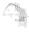
図1は、本発明の実施の形態1にかかる超音波手術装置の構成を示す図である。図2は、図1の超音波手術器具の断面図である。実施の形態1にかかる超音波手術装置1は、術者が保持するハンドピース2と、ハンドピース2に取り付けられる超音波トランスデューサ(可動部材)3と、ケーブル14を介して超音波トランスデューサ3が接続される出力制御装置5と、を備える。
(Embodiment 1)
FIG. 1 is a diagram illustrating a configuration of the ultrasonic operation apparatus according to the first embodiment of the present invention. FIG. 2 is a cross-sectional view of the ultrasonic surgical instrument of FIG. In the
超音波トランスデューサ3は、略円筒状をなす振動子カバー10に内蔵された超音波振動子11を有する。本実施の形態1において、超音波振動子11は、例えば、円環状をなす複数の圧電素子11aが振動子カバー10の長軸方向に配列されることによって構成されている。また、超音波振動子11の挿入部には、超音波振動の振幅拡大を行うホーン12の基端部が連結されている。また、ホーン12は、絶縁部材10c(図4参照)を介して振動子カバー10の内部に固定され、ホーン12の先端部は、挿入部10aから外部に突出されている。
The
ケーブル14は、超音波トランスデューサ3の振動子カバー10の基端側から延出し、超音波トランスデューサ3は、ケーブル14を介して出力制御装置5に接続されている。出力制御装置5には、出力モードに応じた駆動信号の出力をオンまたはオフするためのフットスイッチ17が、ケーブル17aを介して接続されている。
The cable 14 extends from the base end side of the
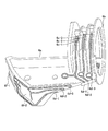
ハンドピース2は、超音波振動を超音波トランスデューサ3が取り付けられる基端側から先端側へと伝達する導波体23を内蔵したハンドピース本体20と、ハンドピース本体20に軸部22を介して揺動自在(回動自在)に軸支されたクランプアーム21と、を有する鉗子型(鋏型)の処置具によって構成されている。
The
ハンドピース本体20は、略円錐形状をなすハウジング25と、このハウジング25に保持されたシース26と、を有している。
The
ハウジング25は、例えば、左右に分割された一対の樹脂成型品からなるハウジング部材が化学的手段または機械的手段により互いに接合されたものである。また、ハウジング25の基端側であって、ハウジング25の中心軸Oからオフセットした位置には、第1の指かけ部28が一体形成されている。第1の指かけ部28の中心軸O側には、超音波トランスデューサ3の挿入部10aを着脱自在に連結するためのコネクタ6が配置されている。
The
さらに、ハウジング25の第1の指かけ部28の前縁部には、2つのスイッチボタン30a、30bが設けられている。これらスイッチボタン30a、30bは、例えば、術者等が第1の指かけ部28に中指と薬指、あるいは薬指と小指を挿入した状態において、当該術者等の人差し指(及び、中指)が臨む位置に配設され、スイッチボタン30a、30bの押圧により、術者の操作が入力される。スイッチボタン30a、30bが設けられるハウジング25の内周方向側には、コネクタ6のスイッチ部6f−1、6f−2が設けられ(図3Cおよび図3E参照)、スイッチ部6f−1は、スイッチボタン30aでの入力操作により開閉状態が切り替えられる。同様に、スイッチ部6f−2は、スイッチボタン30bでの入力操作により開閉状態が切り替えられる。
Further, two
シース26は、主としてハウジング25内に挿通され、一部がハウジング25の外部に延出している。このシース26の内部には、導電性の金属からなる導波体23が、ゴムリング等の弾性部材(図示せず)あるいはプラスチック部材、または導波体23の一部の径を大きくしたフランジを介して保持されている。
The
シース26の基端側はコネクタ6内に配置され、シース26の基端側の内部には、超音波トランスデューサ3の挿入部10aがコネクタ6に連結された際に、挿入部10aから突出するホーン12の先端部が挿入される。ここで、ホーン12の先端部は導波体23の基端部に対して螺合等によって連結可能となっており、この連結により、ホーン12と導波体23と音響的及び電気的に接続される。これにより、導波体23には、超音波トランスデューサ3の超音波振動子11で発生した超音波振動が伝達されるとともに、出力制御装置5から出力された高周波電流(駆動信号)が伝達される。超音波トランスデューサ3は、ケーブル14の絡まり防止の観点から、ハウジング25に対して相対的に回転する状態で取り付けられる。
The proximal end of the
一方、シース26の先端部側は外径が縮径し、収縮したシース26の先端からは、導波体23の先端部に設けられた超音波プローブ27が突出されている。なお、本実施形態1において、超音波プローブ27は、導電性の金属によって導波体23と一体形成されるものであり、これら導波体23及び超音波プローブ27によって、プローブユニット24が構成されている。
On the other hand, the outer diameter of the distal end of the
超音波プローブ27は、先端部が略「J」字状に湾曲されている。本実施形態1において、この超音波プローブ27は、生体組織に対して超音波振動を伝達する機能の他に、生体組織に対して高周波電流を伝達する第1の電極部としての機能を有する。
The tip of the
クランプアーム21は、左右に分割された一対のアーム部材が、化学的手段または機械的手段により互いに接合されたロッド状の部材によって構成されている。アーム部材の中途に凹部が設けられ、この凹部がクランプアーム21の長手方向に延在する開口部30をなす。この開口部30には、シース26の先端側が挿通され、これら開口部30の内面側とシース26の外面側とが軸部22を介して連結されることにより、クランプアーム21は、ハンドピース本体20に対して揺動自在(回動自在)に軸支されている。
The
クランプアーム21の基端部には、ハンドピース本体20に設けられた第1の指かけ部28と対をなす第2の指かけ部29が連設されている。この第2の指かけ部29には、例えば、術者等の親指を挿入するのに好適な環状をなして構成されている。そして、例えば、術者等が第1の指かけ部28に挿入した指(例えば、薬指及び小指)と第2の指かけ部29に挿入した指(例えば、親指)とを相対的に動作させることにより、クランプアーム21は、軸部22を支点として揺動動作される。
At the base end of the
一方、軸部22を介してハンドピース本体20と交差するクランプアーム21の先端側には、クランプアーム21が揺動動作される際に、シース26との干渉を回避するための湾曲部31が設けられている。さらに、この湾曲部31の先端側には、超音波プローブ27に対向する台座32が設けられている。この台座32には、導電性の金属からなるジョー33が設けられている。
On the other hand, a bending
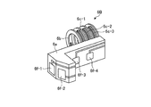
次に、図を参照して、本実施の形態1にかかるコネクタ6、およびコネクタ6と超音波トランスデューサ3との接続に関して説明する。図3Aは、図1の超音波手術器具1で使用するコネクタ6の斜視図である。図3Bは、コネクタ6のリング部側からの斜視図である。図3Cは、コネクタ6の金属配線側からの斜視図である。図3Dは、コネクタ6のリング部のトランスデューサ挿入側からの斜視図である。図3Eは、スイッチ部側からの斜視図である。図4は、超音波トランスデューサ3の挿入部10aの断面図である。
Next, the connector 6 according to the first embodiment and the connection between the connector 6 and the
コネクタ6は、コネクタ本体部6aと、超音波トランスデューサ3の振動子カバー10の挿入部10aを挿入するリング部6bと、リング部6bに挿入された挿入部10aに押圧力を与える切片6c−1、6c−2、6c−3と、第2の導電部6e−1、6e−2、6e−3と、第3の導電部6d−1、6d−2、6d−3と、スイッチ部6f−1、6f−2と、を備える。
The connector 6 includes a
切片6c−1、6c−2、6c−3は、円弧状をなしている。切片6c−1、6c−2、6c−3は、円弧状の基端側でリング部6bに支持されるとともに、円弧状の先端部で超音波トランスデューサ3の挿入部10aを押圧する。超音波トランスデューサ3の挿入部10aと当接する切片6c−1、6c−2、6c−3の内周側には、第2の導電部6e−1、6e−2、6e−3がそれぞれ形成されている。切片6c−1、6c−2、6c−3は、第2の導電部6e−1、6e−2、6e−3がリング部6bの中心に対して対称となるように、リング部6bの両側に対に形成されている。
The
コネクタ本体部6aのハウジング25の内周方向と接する側には、スイッチ部6f−1、6f−2が設けられている。スイッチ部6f−1、6f−2は、スイッチボタン30a、30bでの入力操作により開閉状態が切り替えられる。
第3の導電部6d−1、6d−2、6d−3は、切片6c−1、6c−2、6c−3の面のうち第2の導電部6e−1、6e−2、6e−3が形成される面と対向する面であって、円弧状の先端側から基端側に延伸するように形成されている。第3の導電部6d−1、6d−2、6d−3を第2の導電部6e−1、6e−2、6e−3が形成される面と対向する面、すなわち切片6c−1、6c−2、6c−3の外周側に形成することにより、リング部6b内への超音波トランスデューサ3の挿入により切片6c−1、6c−2、6c−3が押し広げられた場合でも断線を防止することができる。第3の導電部6d−1、6d−2、6d−3は、スイッチ部6f−1、6f−2と第2の導電部6e−1、6e−2、6e−3とを接続する配線部である。第3の導電部6d−1は、スイッチ部6f−1と第2の導電部6e−1とを電気的に接続し、第3の導電部6d−2は、スイッチ部6f−2と第2の導電部6e−2とを電気的に接続する。第3の導電部6d−3は、スイッチ部6f−1、6f−2と第2の導電部6e−3とを電気的に接続する。第3の導電部6d−3は、スイッチ部6f−1、6f−2のグランド線である。
The third
また、図4に示すように、コネクタ6のリング部6bに挿入される超音波トランスデューサ3の挿入部10aの外周部には、第1の導電部10b−1、10b−2、10b−3が形成されている。超音波トランスデューサ3がコネクタ6に挿入された状態では、第2の導電部6e−1に第1の導電部10b−1が接触し、第2の導電部6e−2に第1の導電部10b−2が接触し、第2の導電部6e−3に第1の導電部10b−3が接触する。
As shown in FIG. 4, first
上記のように、スイッチボタン30a、スイッチ部6f−1、第3の導電部6d−1、第2の導電部6e−1および第1の導電部10b−1は、ケーブル14内の図示しない電気信号線を介して出力制御装置5まで、独立した第1の電気信号回路を構成する。また、スイッチボタン30b、スイッチ部6f−2、第3の導電部6d−2、第2の導電部6e−2および第1の導電部10b−2は、ケーブル14内の図示しない電気信号線を介して出力制御装置5まで、独立した第2の電気信号回路を構成する。さらに、スイッチ部6f−1および6f−2、第3の導電部6d−3、第2の導電部6e−3および第1の導電部10b−3は、ケーブル14内の図示しない電気信号線を介して出力制御装置5まで、独立したグランド経路を形成している。
As described above, the
スイッチボタン30aを押圧することにより、スイッチ部6f−1が閉状態になり、スイッチ部6f−1で第1の電気信号経路とグランド経路との間が電気的に接続される。これにより、スイッチ部6f−1から出力制御装置5に電気信号が伝達される。そして、例えば出力制御装置5内の超音波制御部から電気信号線を介して超音波振動子11に電流が供給され、超音波振動子11で超音波振動が発生すると同時に、出力制御装置5内の高周波電流制御部から高周波電流が出力する状態に切替えられる。また、スイッチボタン30bを押圧することにより、スイッチ部6f−2が閉状態になり、スイッチ部6f−2で第2の電気信号経路とグランド経路との間が電気的に接続される。これにより、スイッチ部6f−2から出力制御装置5に電気信号が伝達される。そして、例えば高周波電流制御部のみから高周波電流が出力され、超音波振動を発生しない状態に切替えられる。
By pressing the
コネクタ6は、第2の導電部6e−1、6e−2、6e−3、第3の導電部6d−1、6d−2、6d−3、およびスイッチ部6f−1、6f−2が三次元回路をなす成形回路部品(Molded Interconnect Device、MID)である。第2の導電部6e−1、6e−2、6e−3、第3の導電部6d−1、6d−2、6d−3、およびスイッチ部6f−1、6f−2をレーザ照射およびその後のメッキにより一体的に形成するため、コネクタ6内での電気的な接続部がなく、確実な導通を達成できる。一方、コネクタ本体部6a、リング部6b、および切片6c−1、6c−2、6c−3は、射出成形可能な樹脂材料からなる。切片6c−1、6c−2、6c−3に押圧力を付与するとともに、超音波トランスデューサ3の回転の妨げとならないために、曲げ弾性率が1000MPa以上5000MPa以下の樹脂から形成することが好ましい。また、繰り返しの着脱等の負荷による割れを防止するため、降伏ひずみが3%以上の樹脂から形成されることが好ましい。
In the connector 6, the second
従来、スイッチボタン30a、30bと超音波トランスデューサ3との間の電気信号の伝達は、独立した導電リング(第2の導電部と第3の導電部に相当)をコネクタに嵌合し、スイッチ部が形成された制御基板と該コネクタとをフレキシブル基板で接続することにより伝送されていた。本実施の形態1では、スイッチボタン30a、30bと超音波トランスデューサ3との間の電気信号の伝達を、MIDであるコネクタ6により行うことができるため、ハンドピース2の製造工程を簡素化できるとともに、製造コストも低減可能となる。
Conventionally, transmission of an electric signal between the
実施の形態1では、ハンドピース2としてインライングリップのものを例として説明したが、これに限定されるものではなく、フロントドライブグリップのものにも適用可能である。以下、フロントドライブグリップのハンドピースで使用するコネクタについて説明する。図5Aは、実施の形態1の変形例1にかかるコネクタの斜視図である。図5Bは、図5Aのコネクタのハンドピース内での配置を示す図である。
In the first embodiment, the
図5Bに示すように、変形例1にかかるフロントドライブグリップのハンドピース2Aでは、ハンドピース20Aの第1の指かけ部28Aの上方にスイッチボタン30a、30bが設けられるとともに、グリップ35の基端部近傍にスイッチボタン30c、30dが設けられている。
As shown in FIG. 5B, in the
コネクタ6Aは、コネクタ本体部6aに、4つのスイッチ部6f−1、6f−2、6f−3、6f−4を備える。スイッチ部6f−1、6f−2は、スイッチボタン30a、30bが押圧される際に当接する位置、スイッチ部6f−3、6f−4はスイッチボタン30c、30dが押圧される際に当接する位置にそれぞれ形成されている。スイッチ部6f−1、6f−2、6f−3およびf−4は、術者が中指、人差し指または親指でスイッチボタン30a、30b、30c、30dを押圧することにより開閉状態が切り替えられる。
The
また、フロントドライブグリップのハンドピースで使用するコネクタは下記のようなものであってもよい。図6Aは、実施の形態1の変形例2にかかるコネクタの斜視図である。図6Bは、図6Aのコネクタのハンドピース内での配置を示す図である。 The connector used in the handpiece of the front drive grip may be as follows. FIG. 6A is a perspective view of a connector according to a second modification of the first embodiment. FIG. 6B is a diagram showing the arrangement of the connector of FIG. 6A in the handpiece.
図6Bに示すように、変形例2にかかるフロントドライブグリップのハンドピース2Bでは、ハウジング25Bの第1の指かけ部28Bの上方にスイッチボタン30a、30bが設けられるとともに、グリップ35の基端部近傍の方面(右利きの術者がハンドピース2Bを保持した際に親指が臨む位置)にスイッチボタン30eが設けられている。
As shown in FIG. 6B, in the
コネクタ6Bは、コネクタ本体部6aに、4つのスイッチ部6f−1、6f−2、6f−3、6f−4を備える。スイッチ部6f−1、6f−2は、スイッチボタン30a、30bが押圧される際に当接する位置、スイッチ部6f−3、6f−4はスイッチボタン30eの押圧(左右の端部の一方)に伴い当接する位置にそれぞれ形成されている。スイッチ部6f−1、6f−2、6f−3およびf−4は、術者が中指、人差し指または親指でスイッチボタン30a、30b、30eを押圧することにより開閉状態が切り替えられる。
The
コネクタ6Aおよび6Bのような形状とすることにより、超音波トランスデューサとハンドピース20Aおよび20Bとの確実な導通を達成できる。また、フロントドライブグリップのハンドピースにおいても製造工程を簡素化できるとともに、製造コストを低減可能である。
By adopting a shape like the
また、特開2013−192952号公報に開示されるペンシル型の手術器具においても、スイッチ部とコネクタとをMIDで一体形成することにより、確実な導通を達成でき、簡易な製造工程により、製造コストを低減可能である。 Also, in the pencil-type surgical instrument disclosed in Japanese Patent Application Laid-Open No. 2013-192952, reliable conduction can be achieved by integrally forming the switch portion and the connector with the MID, and the manufacturing cost is reduced by a simple manufacturing process. Can be reduced.
(実施の形態2)
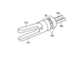
図7Aは、本発明の実施の形態2にかかるバイポーラ処置具の構成を示す図である。図7Bは、図7Aに示すバイポーラ処置具のハンドピース内の概略構成を示す断面図である。図7Cは、図7Aのバイポーラ処置具の先端処置具の拡大図である。図7Dは、図7Aのバイポーラ処置具の駆動部材とコネクタ近傍の拡大斜視図である。バイポーラ処置具は、絶縁された2本の電流供給ラインを有し、この電流供給ラインを介して生体組織の切開、凝固または止血等の処置を行う。
(Embodiment 2)
FIG. 7A is a diagram showing a configuration of the bipolar treatment tool according to the second embodiment of the present invention. FIG. 7B is a cross-sectional view showing a schematic configuration inside the handpiece of the bipolar treatment tool shown in FIG. 7A. FIG. 7C is an enlarged view of the distal treatment device of the bipolar treatment device of FIG. 7A. FIG. 7D is an enlarged perspective view of the vicinity of the drive member and the connector of the bipolar treatment tool of FIG. 7A. The bipolar treatment tool has two insulated current supply lines, and performs treatment such as incision, coagulation, or hemostasis of a living tissue via the current supply lines.
バイポーラ処置具のハンドピース2Cは、ハンドピース本体20Cと、ハンドピース本体20Cの下方に揺動可能に取り付けられる第2の指かけ部28Cと、ハンドピース本体20Cの下方に一体形成されるグリップ35Cと、ハンドピース本体20Cの先端側から延出するシース26Cと、シース26Cの先端側の屈曲部36と、把持部37a、37bと、を備える。
The
ハンドピース2Cは、ダイヤル38を回すことにより、ダイヤル38の軸38a周りの回転は、ギア39を介してチェーン41の軸41a周りの回転とされる。チェーン41の回転により、シース26C内の導電材料からなる2本の駆動部材(可動部材)40a、40bの進退運動に変換される。なお、チェーン41に替えてワイヤを使用することもできる。2本の駆動部材40a、40bおよび把持部37a、37bが、電流供給ラインを構成する。
By rotating the
駆動部材40a、40bの先端は、屈曲部36を構成する駒36aの基端側に挿入され、先端側の駒36aに固定されている。ダイヤル38の回転による駆動部材40a、40bの進退によって、屈曲部36を屈折する。
The distal ends of the driving
コネクタ6Cは、2本の駆動部材40a、40bの内側から外側に押圧する切片6c−1、6c−2と、切片6c−1、6c−2に設けられ、駆動部材40a、40bに当接して、駆動部材40a、40bとハンドピース2Cとを電気的に接続する第2の導電部と、第3の導電部6d−1、6d−2と、スイッチ部6f−1、6f−2と、を備える。第2の導電部は、図7A〜図7Dで図示されていないが、切片6c−4、6c−5の駆動部材40a、40bと接する側に形成され、スイッチ部6f−1、6f−2と第3の導電部6d−1、6d−2を介して電気的に接続されている。
The
コネクタ6Cは、屈曲部36を屈曲させる駆動部材40a、40bの進退運動の際も、切片6c−4、6c−5の押圧により確実な導通を達成できる。また、コネクタ6CをMIDとすることにより、バイポーラ処置具のハンドピース2Cにおいても製造工程を簡素化できるとともに、製造コストを低減可能である。
The
1 超音波手術装置
2 ハンドピース
3 超音波トランスデューサ
5 出力制御装置
6 コネクタ
6a コネクタ本体部
6b リング部
6c−1、6c−2、6c−3 切片
6d−1、6d−2、6d−3 第3の導電部
6e−1、6e−2、6e−3 第2の導電部
6f−1、6f−2、6f−3、6f−4 スイッチ部
10 振動子カバー
10a 挿入部
10b−1、10b−2、10b−3 第1の導電部
10c 絶縁部材
11 超音波振動子
11a 圧電素子
12 ホーン
14、17a ケーブル
17 フットスイッチ
20 ハンドピース本体
21 クランプアーム
22 軸部
23 導波体
24 プローブユニット
25、25A、25B ハウジング
26、26C シース
27 超音波プローブ
28、28A、28B 第1の指かけ部
29 第2の指かけ部
30a、30b、30c、30d、30e スイッチボタン
31 湾曲部
32 台座
33 ジョー
35、35C グリップ
36 屈曲部
37a、37b 把持部
38 ダイヤル
38a、41a 軸
39 ギア
40a、40b 駆動部材
41 チェーン
DESCRIPTION OF
Claims (5)
前記ハンドピースに対して相対的に移動することにより、被検体を処置する処置部に駆動伝達するバイポーラ処置具用の導電材料からなる2本の駆動部材と、
前記ハンドピース内に配置され、前記駆動部材に押圧力を与える切片を有するコネクタと、
を備え、
前記駆動部材が第1の導電部をなし、前記コネクタの前記切片上には、前記第1の導電部と当接して、前記駆動部材と前記ハンドピースとを電気的に接続する第2の導電部が形成され、
前記コネクタの前記第2の導電部は、三次元回路をなす成形回路部品であり、
前記コネクタは、並列される前記2本の駆動部材を、前記2本の駆動部材の内側から外側に押圧するよう前記切片が配置されることを特徴とする手術器具。 With a handpiece,
Two drive members made of a conductive material for a bipolar treatment tool for transmitting drive to a treatment section for treating a subject by relatively moving with respect to the handpiece;
A connector disposed in the handpiece and having a section for applying a pressing force to the driving member;
With
The drive member forms a first conductive portion, and a second conductive portion is provided on the section of the connector, the second conductive portion being in contact with the first conductive portion to electrically connect the drive member and the handpiece. Part is formed,
The second conductive portion of the connector is a molded circuit component forming a three-dimensional circuit,
The surgical instrument according to claim 1, wherein the connector is arranged such that the section presses the two driving members arranged in parallel from the inside to the outside of the two driving members.
2本の導電材料からなる駆動部材を、前記2本の駆動部材の内側から外側に押圧する切片と、
前記切片に設けられ、前記2本の駆動部材に当接して電気的に接続する第2の導電部と、
を備え、
前記第2の導電部が三次元回路をなす成形回路部品であることを特徴とするコネクタ。 A connector for a bipolar treatment tool,
A section for pressing a drive member made of two conductive materials from the inside to the outside of the two drive members,
Provided in the sections and a second conductive portion for electrically connecting contact with the front SL two driving members,
With
The connector wherein the second conductive portion is a molded circuit component forming a three-dimensional circuit.
Priority Applications (4)
| Application Number | Priority Date | Filing Date | Title |
|---|---|---|---|
| JP2015254881A JP6626711B2 (en) | 2015-12-25 | 2015-12-25 | Surgical instruments and connectors |
| CN201680074682.8A CN108472057B (en) | 2015-12-25 | 2016-12-14 | Surgical instrument and connector |
| PCT/JP2016/087275 WO2017110630A1 (en) | 2015-12-25 | 2016-12-14 | Surgical instrument and connector |
| US16/015,847 US11213342B2 (en) | 2015-12-25 | 2018-06-22 | Surgical instrument and connector |
Applications Claiming Priority (1)
| Application Number | Priority Date | Filing Date | Title |
|---|---|---|---|
| JP2015254881A JP6626711B2 (en) | 2015-12-25 | 2015-12-25 | Surgical instruments and connectors |
Publications (3)
| Publication Number | Publication Date |
|---|---|
| JP2017113460A JP2017113460A (en) | 2017-06-29 |
| JP2017113460A5 JP2017113460A5 (en) | 2018-09-13 |
| JP6626711B2 true JP6626711B2 (en) | 2019-12-25 |
Family
ID=59090245
Family Applications (1)
| Application Number | Title | Priority Date | Filing Date |
|---|---|---|---|
| JP2015254881A Active JP6626711B2 (en) | 2015-12-25 | 2015-12-25 | Surgical instruments and connectors |
Country Status (4)
| Country | Link |
|---|---|
| US (1) | US11213342B2 (en) |
| JP (1) | JP6626711B2 (en) |
| CN (1) | CN108472057B (en) |
| WO (1) | WO2017110630A1 (en) |
Families Citing this family (4)
| Publication number | Priority date | Publication date | Assignee | Title |
|---|---|---|---|---|
| WO2019016894A1 (en) * | 2017-07-19 | 2019-01-24 | オリンパス株式会社 | Generator, coupler, and vibration generation device |
| CN113329704A (en) * | 2019-01-23 | 2021-08-31 | 奥林巴斯株式会社 | Energy treatment instrument and method for manufacturing energy treatment instrument |
| US20220257304A1 (en) * | 2021-02-12 | 2022-08-18 | Covidien Lp | Continuous rotation cable for surgical instrument |
| PL4140419T3 (en) * | 2021-08-23 | 2024-04-22 | Sra Developments Ltd. | Ultrasonic surgical apparatus and handpiece therefor |
Family Cites Families (9)
| Publication number | Priority date | Publication date | Assignee | Title |
|---|---|---|---|---|
| US7632270B2 (en) * | 2004-01-26 | 2009-12-15 | Bovie Medical Corporation | Multi-mode surgical instrument |
| US8574252B2 (en) | 2006-06-01 | 2013-11-05 | Ethicon Endo-Surgery, Inc. | Ultrasonic blade support |
| US8870867B2 (en) * | 2008-02-06 | 2014-10-28 | Aesculap Ag | Articulable electrosurgical instrument with a stabilizable articulation actuator |
| US20090248050A1 (en) * | 2008-03-27 | 2009-10-01 | Yuji Hirai | Ultrasonic operating apparatus |
| US20120116261A1 (en) * | 2010-11-05 | 2012-05-10 | Mumaw Daniel J | Surgical instrument with slip ring assembly to power ultrasonic transducer |
| WO2012128362A1 (en) | 2011-03-24 | 2012-09-27 | オリンパスメディカルシステムズ株式会社 | Surgical gripping device |
| US8734476B2 (en) | 2011-10-13 | 2014-05-27 | Ethicon Endo-Surgery, Inc. | Coupling for slip ring assembly and ultrasonic transducer in surgical instrument |
| EP2745792B1 (en) | 2011-10-26 | 2019-09-11 | Olympus Corporation | Ultrasound treatment instrument |
| JP5990026B2 (en) * | 2012-04-12 | 2016-09-07 | カール シュトルツ ゲゼルシャフト ミット ベシュレンクテル ハフツング ウント コンパニー コマンディートゲゼルシャフト | Medical manipulator |
-
2015
- 2015-12-25 JP JP2015254881A patent/JP6626711B2/en active Active
-
2016
- 2016-12-14 WO PCT/JP2016/087275 patent/WO2017110630A1/en active Application Filing
- 2016-12-14 CN CN201680074682.8A patent/CN108472057B/en active Active
-
2018
- 2018-06-22 US US16/015,847 patent/US11213342B2/en active Active
Also Published As
| Publication number | Publication date |
|---|---|
| CN108472057B (en) | 2021-05-11 |
| CN108472057A (en) | 2018-08-31 |
| US11213342B2 (en) | 2022-01-04 |
| US20180296238A1 (en) | 2018-10-18 |
| WO2017110630A1 (en) | 2017-06-29 |
| JP2017113460A (en) | 2017-06-29 |
Similar Documents
| Publication | Publication Date | Title |
|---|---|---|
| US9901754B2 (en) | Grasping treatment apparatus and grasping unit | |
| JP6626711B2 (en) | Surgical instruments and connectors | |
| JP5989275B2 (en) | Grip unit and bipolar treatment instrument | |
| JP4157574B2 (en) | Surgical instrument | |
| WO2013154159A1 (en) | Medical manipulator | |
| WO2013115036A1 (en) | Gripping and treating device | |
| JP5750705B2 (en) | Treatment tool using ultrasonic vibration | |
| JPWO2012128362A1 (en) | Grasping treatment device | |
| KR101418717B1 (en) | Master gripper of surgical robot | |
| KR101359475B1 (en) | Surgical operating apparatus | |
| JP6006518B2 (en) | Medical manipulator | |
| US20180271587A1 (en) | Energy treatment instrument | |
| JPWO2018011918A1 (en) | Grasping treatment instrument | |
| JP6153686B2 (en) | Medical materials, medical equipment | |
| JP5990026B2 (en) | Medical manipulator | |
| JP6084349B1 (en) | Ultrasonic treatment device | |
| JP2016002410A (en) | Forceps device and surgical system | |
| WO2020152811A1 (en) | Energy treatment tool | |
| JP4436556B2 (en) | Surgical ultrasonic treatment device | |
| JP4059658B2 (en) | Surgical forceps | |
| WO2022029895A1 (en) | Ultrasonic treatment tool and manufacturing method for ultrasonic treatment tool | |
| US20230048948A1 (en) | Treatment instrument | |
| WO2020152809A1 (en) | Energy treatment tool and method for producing energy treatment tool | |
| WO2016075745A1 (en) | Medical treatment apparatus | |
| JP2005342082A (en) | Endoscopic treatment system |
Legal Events
| Date | Code | Title | Description |
|---|---|---|---|
| A521 | Request for written amendment filed |
Free format text: JAPANESE INTERMEDIATE CODE: A523 Effective date: 20180802 |
|
| A621 | Written request for application examination |
Free format text: JAPANESE INTERMEDIATE CODE: A621 Effective date: 20180802 |
|
| A131 | Notification of reasons for refusal |
Free format text: JAPANESE INTERMEDIATE CODE: A131 Effective date: 20190611 |
|
| A521 | Request for written amendment filed |
Free format text: JAPANESE INTERMEDIATE CODE: A523 Effective date: 20190801 |
|
| TRDD | Decision of grant or rejection written | ||
| A01 | Written decision to grant a patent or to grant a registration (utility model) |
Free format text: JAPANESE INTERMEDIATE CODE: A01 Effective date: 20191112 |
|
| A61 | First payment of annual fees (during grant procedure) |
Free format text: JAPANESE INTERMEDIATE CODE: A61 Effective date: 20191202 |
|
| R151 | Written notification of patent or utility model registration |
Ref document number: 6626711 Country of ref document: JP Free format text: JAPANESE INTERMEDIATE CODE: R151 |
|
| R250 | Receipt of annual fees |
Free format text: JAPANESE INTERMEDIATE CODE: R250 |
|
| R250 | Receipt of annual fees |
Free format text: JAPANESE INTERMEDIATE CODE: R250 |