JP6626119B2 - Multi-gigabit wireless tunneling system - Google Patents
Multi-gigabit wireless tunneling system Download PDFInfo
- Publication number
- JP6626119B2 JP6626119B2 JP2017548924A JP2017548924A JP6626119B2 JP 6626119 B2 JP6626119 B2 JP 6626119B2 JP 2017548924 A JP2017548924 A JP 2017548924A JP 2017548924 A JP2017548924 A JP 2017548924A JP 6626119 B2 JP6626119 B2 JP 6626119B2
- Authority
- JP
- Japan
- Prior art keywords
- wireless
- state
- local
- processing device
- remote processing
- Prior art date
- Legal status (The legal status is an assumption and is not a legal conclusion. Google has not performed a legal analysis and makes no representation as to the accuracy of the status listed.)
- Active
Links
- 230000005641 tunneling Effects 0.000 title claims description 175
- 238000012545 processing Methods 0.000 claims description 315
- 238000004891 communication Methods 0.000 claims description 61
- 230000005540 biological transmission Effects 0.000 claims description 43
- 238000000034 method Methods 0.000 claims description 30
- 230000004044 response Effects 0.000 claims description 6
- 230000007704 transition Effects 0.000 description 20
- 230000011664 signaling Effects 0.000 description 13
- 238000001514 detection method Methods 0.000 description 8
- 230000006870 function Effects 0.000 description 7
- 238000011144 upstream manufacturing Methods 0.000 description 7
- 238000013461 design Methods 0.000 description 5
- 230000008569 process Effects 0.000 description 4
- 238000012546 transfer Methods 0.000 description 4
- 230000000295 complement effect Effects 0.000 description 3
- 238000012937 correction Methods 0.000 description 3
- 238000003032 molecular docking Methods 0.000 description 3
- 230000000737 periodic effect Effects 0.000 description 3
- 238000012549 training Methods 0.000 description 3
- 238000006243 chemical reaction Methods 0.000 description 2
- 238000010586 diagram Methods 0.000 description 2
- 238000011143 downstream manufacturing Methods 0.000 description 2
- 238000012986 modification Methods 0.000 description 2
- 230000004048 modification Effects 0.000 description 2
- 230000002093 peripheral effect Effects 0.000 description 2
- 230000001960 triggered effect Effects 0.000 description 2
- 230000004075 alteration Effects 0.000 description 1
- 238000013459 approach Methods 0.000 description 1
- 230000009286 beneficial effect Effects 0.000 description 1
- 230000002457 bidirectional effect Effects 0.000 description 1
- 230000008859 change Effects 0.000 description 1
- 125000004122 cyclic group Chemical group 0.000 description 1
- 230000001934 delay Effects 0.000 description 1
- 238000009795 derivation Methods 0.000 description 1
- 239000011159 matrix material Substances 0.000 description 1
- 230000002085 persistent effect Effects 0.000 description 1
- 230000010287 polarization Effects 0.000 description 1
- 230000009897 systematic effect Effects 0.000 description 1
Images


Classifications
-
- H—ELECTRICITY
- H04—ELECTRIC COMMUNICATION TECHNIQUE
- H04W—WIRELESS COMMUNICATION NETWORKS
- H04W76/00—Connection management
- H04W76/10—Connection setup
- H04W76/12—Setup of transport tunnels
-
- H—ELECTRICITY
- H04—ELECTRIC COMMUNICATION TECHNIQUE
- H04L—TRANSMISSION OF DIGITAL INFORMATION, e.g. TELEGRAPHIC COMMUNICATION
- H04L25/00—Baseband systems
-
- H—ELECTRICITY
- H04—ELECTRIC COMMUNICATION TECHNIQUE
- H04L—TRANSMISSION OF DIGITAL INFORMATION, e.g. TELEGRAPHIC COMMUNICATION
- H04L25/00—Baseband systems
- H04L25/02—Details ; arrangements for supplying electrical power along data transmission lines
-
- H—ELECTRICITY
- H04—ELECTRIC COMMUNICATION TECHNIQUE
- H04L—TRANSMISSION OF DIGITAL INFORMATION, e.g. TELEGRAPHIC COMMUNICATION
- H04L12/00—Data switching networks
- H04L12/28—Data switching networks characterised by path configuration, e.g. LAN [Local Area Networks] or WAN [Wide Area Networks]
- H04L12/46—Interconnection of networks
- H04L12/4633—Interconnection of networks using encapsulation techniques, e.g. tunneling
-
- H—ELECTRICITY
- H04—ELECTRIC COMMUNICATION TECHNIQUE
- H04W—WIRELESS COMMUNICATION NETWORKS
- H04W76/00—Connection management
- H04W76/10—Connection setup
- H04W76/14—Direct-mode setup
Description
本開示の実施形態は、無線通信分野全般に関し、特に、有線通信プロトコルの無線トンネリングに関する。 Embodiments of the present disclosure relate generally to the field of wireless communications, and more particularly, to wireless tunneling of wired communication protocols.
無線トンネリングシステムでは、これまで有線通信リンクで通信されたデータを、代わりに無線チャンネルを通じてトンネリングする。 In wireless tunneling systems, data previously communicated over a wired communication link is tunneled over a wireless channel instead.
従来、無線通信は、有線リンクによる通信に比べて実質的に遅い。従って、従来の無線システムは、例えば、マルチギガビットのデータ転送速度を有するUSB(Universal Serial Bus)、HDMI(High-Definition Media Interface)、及びDP(DisplayPort)等のハイスピードプロトコルをトンネリングすることができない。 Conventionally, wireless communication is substantially slower than communication over a wired link. Therefore, the conventional wireless system cannot tunnel high-speed protocols such as USB (Universal Serial Bus), HDMI (High-Definition Media Interface), and DP (DisplayPort) having a multi-gigabit data transfer rate. .
本開示の無線トンネリングシステムは、2つの処理装置間の通信の適合性を維持しつつ、無線リンクを通じた2つの処理装置間の通信をトンネリングする。 The wireless tunneling system of the present disclosure tunnels communication between two processing devices over a wireless link while maintaining compatibility of the communication between the two processing devices.
一実施形態において、無線トンネリングシステムは、無線リンクを通じて互いに通信する2つの無線トンネリング装置を含む。局所無線トンネリング装置は、有線接続を介してローカル処理装置に連結され、遠隔無線トンネリング装置は、他の有線接続を介してリモート処理装置に連結される。2つの処理装置は、これら2つの処理装置が有線接続を介して接続されているかのように、2つの無線トンネリング装置を使用して、低遅延無線リンクを通じて互いに通信できる。 In one embodiment, a wireless tunneling system includes two wireless tunneling devices that communicate with each other over a wireless link. The local wireless tunneling device is connected to the local processing device via a wired connection, and the remote wireless tunneling device is connected to the remote processing device via another wired connection. The two processing devices can communicate with each other over the low-latency wireless link using the two wireless tunneling devices as if the two processing devices were connected via a wired connection.
一実施形態において、局所無線トンネリング装置は、無線受信機と、処理コンポーネント状態機械と、インタフェース回路とを含む。無線受信機は、遠隔無線トンネリング装置から無線受信信号を受信し、無線受信信号をダウンコンバートして無線受信信号からベースバンド信号を生成するように構成される。処理コンポーネント状態機械は、前記リモート処理装置の遠隔処理状態の情報を含む前記ベースバンド信号に基づき、前記リモート処理装置の遠隔処理状態を予測基づき、リモート処理装置の遠隔処理状態を予測するように構成される。インタフェース回路は、ローカル処理装置に連結され、(i)予測された遠隔処理状態とベースバンド信号に基づき、有線通信プロトコルに準拠した出力信号を生成し、(ii)有線通信プロトコルを通じてローカル処理装置に出力信号を提供するように構成され、前記リモート処理装置の遠隔処理状態の情報は、前記遠隔処理状態のリンク接続性を示す情報および前記遠隔処理状態のリンク電力管理情報を含む。 In one embodiment, a local wireless tunneling device includes a wireless receiver, a processing component state machine, and an interface circuit. The wireless receiver is configured to receive a wireless reception signal from the remote wireless tunneling device, downconvert the wireless reception signal and generate a baseband signal from the wireless reception signal. The processing component state machine is configured to predict a remote processing state of the remote processing apparatus based on the baseband signal including the information of the remote processing state of the remote processing apparatus and to predict a remote processing state of the remote processing apparatus. Is done. The interface circuit is connected to the local processing device, and (i) generates an output signal compliant with the wired communication protocol based on the predicted remote processing state and the baseband signal, and (ii) transmits the output signal to the local processing device through the wired communication protocol. The remote processing status information of the remote processing device is configured to provide an output signal, and includes information indicating the link connectivity of the remote processing status and link power management information of the remote processing status .
1つ以上の実施形態において、局所無線トンネリング装置は、(i)ローカル処理装置から入力信号を受信して、他のベースバンド信号を生成し、(ii)この他のベースバンド信号をアップコンバートして、無線送信信号を生成し、(iii)無線送信信号を送信するように構成された無線送信機をさらに含む。処理コンポーネント状態機械は、(a)処理コンポーネント状態機械の現在の状態、(b)ローカル処理装置から受信した入力、(c)予測された遠隔処理状態のうちの1つ以上に基づき、受信機又は送信機の電力状態を制御してもよい。処理コンポーネント状態機械は、さらに、ローカル処理装置の1つ以上のローカル処理状態を処理コンポーネント状態機械の一つの状態にマッピングし、この一つの状態に基づき、ローカル処理装置のローカル処理状態を示す状態信号を生成するように構成されてもよい。送信機は、さらに、ローカル処理装置のローカル処理状態を示す状態信号と共にベースバンド信号を符号化するように構成されてもよい。 In one or more embodiments, the local wireless tunneling device (i) receives an input signal from a local processing device and generates another baseband signal, and (ii) upconverts the other baseband signal. And generating a wireless transmission signal and (iii) transmitting a wireless transmission signal. The processing component state machine may be configured to perform one or more of: (a) a current state of the processing component state machine, (b) an input received from a local processing device, (c) a predicted remote processing state, The power state of the transmitter may be controlled. The processing component state machine further maps one or more local processing states of the local processing device to one state of the processing component state machine and, based on the one state, a status signal indicating a local processing state of the local processing device. May be configured to be generated. The transmitter may be further configured to encode the baseband signal with a status signal indicating a local processing state of the local processing device.
1つ以上の実施形態において、局所無線トンネリング装置は、自身の現在の状態とリモート処理装置の予測された遠隔処理状態に基づき、無線受信機の無線コンポーネント状態を判定するように構成された無線コンポーネント状態機械をさらに含む。無線コンポーネント状態機械は、自身の現在の状態とリモート処理装置の予測された遠隔処理状態に基づいて判定された無線コンポーネント状態に応じて、無線受信機の動作モードを制御してもよい。 In one or more embodiments, the local wireless tunneling device is configured to determine a wireless component state of the wireless receiver based on its current state and the predicted remote processing state of the remote processing device. Further includes a state machine. The wireless component state machine may control the operating mode of the wireless receiver according to the wireless component state determined based on its current state and the predicted remote processing state of the remote processing device.
1つ以上の実施形態において、ベースバンド信号は、リモート処理装置の以前の状態を示す状態信号と共に符号化される。処理コンポーネント状態機械は、ベースバンド信号の状態信号に基づき、リモート処理装置の遠隔処理状態を予測するように構成されてもよい。 In one or more embodiments, the baseband signal is encoded with a status signal indicating a previous status of the remote processing device. The processing component state machine may be configured to predict a remote processing state of the remote processing device based on the state signal of the baseband signal.
1つ以上の実施形態において、処理コンポーネント状態機械は、無線受信信号に対応するベースバンド信号の一部に基づき、リモート処理装置の遠隔処理状態を予測するように構成される。 In one or more embodiments, the processing component state machine is configured to predict a remote processing state of the remote processing device based on a portion of the baseband signal corresponding to the wireless received signal.
1つ以上の実施形態において、処理コンポーネント状態機械は、ローカル処理装置の1つ以上のローカル処理状態に基づき、リモート処理装置の遠隔処理状態を予測するように構成される。 In one or more embodiments, the processing component state machine is configured to predict a remote processing state of a remote processing device based on one or more local processing states of the local processing device.
1つ以上の実施形態において、有線通信プロトコルを用いた、ローカル処理装置とリモート処理装置の間の通信の適合性を維持しつつ、ローカル処理装置とリモート処理装置の間の通信を無線でトンネリングする方法を開示する。この方法は、無線受信機により、遠隔無線トンネリング装置から無線受信信号を受信し、無線受信機により、無線受信信号をダウンコンバートして、無線受信信号からベースバンド信号を生成し、処理コンポーネント状態機械により、前記リモート処理装置の遠隔処理状態の情報を含む前記ベースバンド信号に基づき、前記リモート処理装置の遠隔処理状態を予測基づき、リモート処理装置の遠隔処理状態を予測し、ローカル処理装置に連結されたインタフェース回路により、予測された遠隔処理状態とベースバンド信号に基づき、有線通信プロトコルに準拠した出力信号を生成し、インタフェース回路により、有線通信プロトコルを通じて、ローカル処理装置に出力信号を提供することを含み、前記リモート処理装置の遠隔処理状態の情報は、前記遠隔処理状態のリンク接続性を示す情報および前記遠隔処理状態のリンク電力管理情報を含む。 In one or more embodiments, wirelessly tunnel communication between a local processing device and a remote processing device while maintaining compatibility of communication between the local processing device and the remote processing device using a wired communication protocol. A method is disclosed. The method includes receiving, by a wireless receiver, a wireless receive signal from a remote wireless tunneling device, downconverting the wireless receive signal by the wireless receiver, generating a baseband signal from the wireless receive signal, and processing a component state machine. The remote processing device predicts the remote processing status of the remote processing device based on the baseband signal including the information of the remote processing status of the remote processing device, predicts the remote processing status of the remote processing device, and is connected to the local processing device. An interface circuit for generating an output signal compliant with the wired communication protocol based on the predicted remote processing state and the baseband signal, and providing the output signal to the local processing device through the wired communication protocol by the interface circuit. seen including, information of a remote processing state of the remote processing device , Including the remote information indicating a link connectivity processing state and link power management information of said remote processing state.
本明細書に開示の実施形態の教示は、添付の図面とともに以下の詳細な説明を考慮することにより、容易に理解することができる。 The teachings of the embodiments disclosed herein can be readily understood by considering the following detailed description in conjunction with the accompanying drawings.
本明細書に記載の特徴及び効果は、すべてを網羅するものでなく、特に、図面、明細書、及び請求書の参照により、当業者には多くの追加的特徴及び効果が明らかとなるであろう。さらに、本明細書において使用される言語は、主として読み易さ及び指導的目的のために選択されたものであり、発明の主題を厳密に説明したり、制限するために選択されたものでないことに留意しなければならない。 The features and advantages described herein are not exhaustive, and many additional features and advantages will become apparent to those skilled in the art, particularly with reference to the drawings, specification, and claims. Would. Furthermore, the language used in the present specification has been selected primarily for readability and instructional purposes, and not for the purpose of precisely describing or limiting the subject matter of the invention. You have to keep in mind.
図面及び以下の説明は、単なる例示としての好適な実施形態に関連する。以下の検討より、本発明の原則から逸脱することなく採用されてもよい、実行可能な代替として、本開示の構造及び方法の代替実施形態が容易に認識されることに留意しなければならない。 The drawings and the following description relate to preferred embodiments by way of example only. It should be noted from the following discussion that alternative embodiments of the structures and methods of this disclosure will be readily recognized as viable alternatives that may be employed without departing from the principles of the present invention.
以降、添付の図面に例示される、本発明のいくつかの実施形態を詳細に説明する。図中、実際的な同様又は類似の参照符号が使用されることがあり、同様又は類似の機能を示すことがあることに留意しなければならない。図面は、例示のみを目的として実施形態を示している。当業者は、以下の説明より、本明細書に記載の原則から逸脱することなく、本明細書に示された構造及び方法の代替実施形態が採用されてもよいことを容易に認識するであろう。 Hereinafter, some embodiments of the present invention, illustrated in the accompanying drawings, will be described in detail. It should be noted that in the figures, practically similar or similar reference numerals may be used and may indicate similar or similar functions. The drawings illustrate the embodiments for purposes of illustration only. Those skilled in the art, from the following description, will readily appreciate that alternative embodiments of the structures and methods shown herein may be employed without departing from the principles described herein. Would.
システム概要
本明細書中の実施形態は、主に、ホスト、デバイス、及びハブを備える、接続トポロジーにおける任意のノードに差し込むことのできるトンネリングシステムの観点において説明する。いくつかの実施形態において、トンネリングシステムは、USB3.0システムの観点で動作してもよい。しかしながら、本明細書における実施形態は、USB規格の異なるバージョン等、他の通信プロトコルや、HDMI、DisplayPort等、完全に異なるプロトコル、又はその他のシリアル通信プロトコルを使用した通信に使用されてもよい。
System Overview Embodiments herein are described primarily in terms of a tunneling system that can be plugged into any node in a connection topology, including hosts, devices, and hubs. In some embodiments, the tunneling system may operate in terms of a USB 3.0 system. However, the embodiments herein may be used for communication using other communication protocols, such as different versions of the USB standard, or completely different protocols, such as HDMI, DisplayPort, or other serial communication protocols.
図1は、無線トンネリングシステム100の実施形態を示す。無線トンネリングシステム100は、無線リンク130を介して第2の演算システム150Bと通信する第1の演算システム150Aを備える。
FIG. 1 shows an embodiment of a
一実施形態において、無線リンク130は、60GHzの無線リンクからなる。無線リンク130は、無線トンネリング装置120が互いに非常に近接している(例えば、数ミリメートル以内)狭域通信に限定されてもよい。無線リンク130によるデータ送信には、例えば、毎秒6ギガビット以上のデータ転送速度を有してもよい。他の実施形態において、無線リンクは、広域通信に好適であってもよく、及び/又は、その他の周波数帯域で実施されてもよい。
In one embodiment,
第1の演算システム150Aは、有線接続116Aを介して無線トンネリング装置120Aに連結された処理装置110Aを含み、第2の演算システム150Bは、有線接続116Bを介して無線トンネリング装置120Bに連結された処理装置110Bを含む。無線トンネリング装置120A及び120B(本明細書中、「無線トンネリング装置120」又は「送受信機120」とも称する)は、無線リンク130を通じて互いに通信し、処理装置110A及び処理装置110B(本明細書中、「処理装置110」又は「ソース装置110」とも称する)間の通信をトンネリングする。処理装置は、有線通信プロトコルに準拠したデータ(一方向性又は双方向性)を他の電子装置と交換することのできる電子装置を含むことができる。処理装置の例として、ソースデバイス、シンクデバイス、ソースデバイスとシンクデバイスの間の中間デバイス、USBホスト/デバイス、ストレージデバイス等が挙げられる。一実施形態において、無線トンネリング装置120は、処理装置110のポート又はケーブル(例えば、USBポート又はケーブル、HDMIポート又はケーブル、又はDisplayPortのポート又はケーブル)に連結可能な脱着式ドングルとして実装される。他の実施形態において、無線トンネリング装置120は、処理装置110に(例えば、プリント回路基板上のトレースを介して)内部連結されるか、又は処理装置110に(例えば、集積回路において)完全に一体化されてもよい。
The first computing system 150A includes a
演算システム150(及びそのコンポーネント)は、アナログ回路コンポーネント、デジタルロジック、ソフトウェア、又はそれらの組み合わせによって実装されてもよい。一実施形態において、演算システム150の1つ以上のコンポーネントは、プロセッサと、プロセッサによる実行時、プロセッサにコンポーネントによる機能を実施させる命令を記憶する非一時的なコンピュータ可読記憶媒体として、実装されてもよい。代替又は追加として、デジタルコンポーネントは、ASIC(Application Specific Integrated Circuit)、FGPA(Field-Programmable Gate Array)として、又はそれらの実装の組み合わせを使用して、実装されてもよい。 The computing system 150 (and its components) may be implemented by analog circuit components, digital logic, software, or a combination thereof. In one embodiment, one or more components of computing system 150 may be implemented as a non-transitory computer-readable storage medium that stores a processor and instructions that, when executed by the processor, cause the processor to perform the functions performed by the component. Good. Alternatively or additionally, the digital component may be implemented as an Application Specific Integrated Circuit (ASIC), a Field-Programmable Gate Array (FGPA), or using a combination of these implementations.
一実施形態において、無線トンネリングシステム100は、USB、HDMI、DisplayPort、又はその他のシリアル通信プロトコル等、従来の有線通信の代替物を提供する。例えば、処理装置110A及び110Bは、これまでのケーブルを介して互いに直接通信するのでなく、代わりに、処理装置110A及び110Bは、各無線トンネリング装置120A、120Bと通信した後、これまでの有線通信を使用して達成することのできる速度を上回る速度で、ハイスピードポイント間シリアル無線リンク130でデータをトンネリングする。
In one embodiment, the
処理装置110A、110Bの観点から、処理装置110A、110Bが従来の構成で直接接続されているかのように、同じ方法で通信が実装されてもよい。そのため、必ずしも、従来の処理装置110A、110Bへの修正が必要とされない(例えば、ソフトウェアの修正が必要ない)。換言すると、無線トンネリング装置120A、120B及びその両者間の無線リンク130は、従来のケーブルの直接的代替物として動作してもよい。例えば、各無線トンネリング装置120A、120Bは、各処理装置110A、110Bの従来のケーブルインタフェースに直接差し込めるようにするインタフェースを含み、無線トンネリング装置120A、120Bは、処理装置110A、110Bにとって、互いに直接接続されているかのような通信を促進する。別の実施形態において、無線トンネリング装置120A、120Bは、それらの処理装置110A、110Bにそれぞれ一体化されてもよい。
From the perspective of
USBを例にとると、USBインタフェースを備えたこれまでの無線装置は、無線装置でUSBプロトコルを終了させ、送信用の異なる無線プロトコルにデータを再符号化する。これまでの無線装置は、USBツリートポロジーにおけるノード(USBハブ、USBデバイス、又はUSBリピータ)としてみることができる。一方、無線トンネリング装置は、非常に低遅延で、修正を行うことなく、且つ、USBプロトコルレイヤを終了させることなく、USBリンクレイヤデータトラフィックを送信できるようにする。このような無線トンネリング装置は、USBトポロジーにみることができない。 Taking USB as an example, a conventional wireless device with a USB interface terminates the USB protocol at the wireless device and re-encodes the data to a different wireless protocol for transmission. Conventional wireless devices can be viewed as nodes (USB hubs, USB devices, or USB repeaters) in a USB tree topology. Wireless tunneling devices, on the other hand, allow USB link layer data traffic to be transmitted with very low delay, without modification, and without terminating the USB protocol layer. Such a wireless tunneling device cannot be seen in a USB topology.
一実施形態において、各無線トンネリング装置120は、接続された処理装置110と通信を行い、無線トンネリング装置120が連結された処理装置110の相手の状態及び動作をミラーリングする。そこで、例えば、無線トンネリング装置120Aは、矢印118で示される通り、処理装置110Bの状態をミラーリングし、無線トンネリング装置120Bは、矢印128で示される通り、処理装置110Aをミラーリングする。従って、無線トンネリング装置120Aから処理装置110Aに通信されるデータには、処理装置110Bから無線トンネリング装置120Bへの通信がミラーリングされ、無線トンネリング装置120Bから処理装置110Bに通信されるデータには、処理装置110Aから無線トンネリング装置120Aへの通信がミラーリングされる。
In one embodiment, each
具体的には、各無線トンネリング装置120は、そのリモート(すなわち、相手方)処理装置110の動作状態(例えば、電力状態又はその他の動作上の状態)を予測し、有線接続116を介して、予測された状態に従い、ローカル処理装置110Aとインタフェースで接続する。例えば、処理装置110Bは、データの速度又は電力管理状態に応じた有線通信プロトコル(例えば、USB)に従って、多数の処理状態のうちの1つで動作する。無線トンネリング装置120Aは、処理装置110Bの動作状態を予測し、処理装置110Bの予測された状態をミラーリングして、有線接続116Aを介して処理装置110Aとインタフェースで接続する。ミラーリングされる状態は、処理装置110Bの動作状態と同一又は略同様であってもよい。一態様において、表4を参照してより詳細に説明する通り、処理装置110の1組の処理状態を、無線トンネリング装置120の一つの状態又はより少ない数の状態にマッピング又は折り畳むことができる。
Specifically, each
無線トンネリング装置120は、送信機122と、受信機124と、状態機械126とを備える。送信機122は、処理装置110からデータを受信し、そのデータを、無線リンク130を介して別の演算システム150の受信機124に送信する。受信機124は、他の演算システム150の送信機122から無線リンク130を介してデータを受信し、受信したデータを処理装置110に提供する。状態機械126は、以下にさらに詳細に説明する通り、高周波数データを送信するための高電力状態と1つ以上の低電力状態との間で無線トンネリング装置120を切り替えることにより、無線トンネリング装置120の電力状態を制御する。無線トンネリング装置120は、さらに、トンネリングされたプロトコルの範囲内で信号化された低電力状態を模倣する。一実施形態において、無線トンネリング装置120は、無線リンク130を介してデータを同時に送受信するように、全二重通信を行うことができる。
The
例えば、図示の実施形態において、処理装置110Aはアップストリーム装置として構成され、状態機械126Aに応じて「ホスト」として動作し、処理装置110Bはダウンストリーム装置として構成され、状態機械126Bに応じて「デバイス」として動作する。「ホスト」として機能する処理装置110Aは、「デバイス」として機能する処理装置110Bの動作、又は、処理装置110Bとの通信を制御する。アップストリーム無線トンネリング装置120Aは、有線接続116Aを介してアップストリーム処理装置110A(すなわち、「ホスト」)とインタフェースで接続し、同時に、ダウンストリーム無線トンネリング装置120Bは、有線接続116Bを介してダウンストリーム処理装置110B(「デバイス」)とインタフェースで接続する。無線トンネリング装置120A及び120Bは、無線リンク130を介して、各処理装置110のステータス、状態、又は制御情報を含むデータを交換する。
For example, in the illustrated embodiment,
一実施形態において、無線トンネリング装置120A、120Bは、実質的に同一の装置である。或いは、無線トンネリング装置120A、120Bは、同様のハイレベルアーキテクチャを有するものの、本明細書に記載の特定のアーキテクチャ特性又は動作特性の異なる、別の補完装置種別である。例えば、一実施形態において、第1の無線トンネリング装置120Aは、ドッキングステーションとして実現された処理装置110Aとともに動作するように構成された第1の装置種別からなり、第2の無線トンネリング装置120Bは、モバイル装置として実現された処理装置110Bとともに動作するように構成された第2の装置種別からなる。一実施形態において、全二重通信を実施するためには、2つの異なる送信機/受信機のアンテナペアが双方向において同時に動作可能となるように、異なる種別の補完無線トンネリング装置120が異なるアンテナ偏波を有する。例えば、無線トンネリング装置120Aは、種別Xの送信アンテナと種別Yの受信アンテナを有してもよく、無線トンネリング装置120Bは、補完種別Yの送信アンテナと種別Xの受信アンテナを有してもよい。さらに、異なる種別の無線トンネリング装置120は、ペアのうちの無線トンネリング装置120の一方の電力効率を最適化するために、異なる制御方式に従って動作してもよい。例えば、第1の無線トンネリング装置120Aがドッキングステーションとともに動作するように構成され、第2の無線トンネリング装置120Bがモバイル装置とともに動作するように構成される時、無線トンネリング装置120A、120Bは、ドッキングステーションによってホストされる無線トンネリング装置120Bを代償にして、モバイル装置によってホストされる無線トンネリング装置120Aの電力消費を下げるため、非対称的に動作してもよい。ドッキングステーションは、通常、持続的電源に接続され、モバイル装置は、電力に制限のあるバッテリに依存するため、このトレードオフが望ましいこともある。
In one embodiment, the wireless tunneling devices 120A, 120B are substantially the same device. Alternatively, wireless tunneling devices 120A, 120B are another complementary device type that have a similar high-level architecture, but differ in certain architectural or operational characteristics described herein. For example, in one embodiment, the first wireless tunneling device 120A comprises a first device type configured to operate with a
一実施形態において、無線トンネリング装置120に関連する装置種別(及びそれに関連する動作)は、無線トンネリング装置120内に永続的に組み込んで設計されてもよい。或いは、無線トンネリング装置120は、スイッチ、コントロールピン(すなわち、チップの制御入力)、又はレジスタ設定に基づき、2つ以上の装置種別間で構成可能であってもよい。補完ペア内の無線トンネリング装置120A、120Bの異なる構成間のアーキテクチャ上の差異及び/又は動作上の差異について、以下にさらに詳細に説明する。
In one embodiment, the device type (and associated operations) associated with the
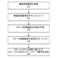
図2は、一実施形態に係る、リモート処理装置110Bからローカル処理装置110Aへの通信をトンネリングする局所無線トンネリング装置120Aの一例としてのプロセスを示す。
FIG. 2 illustrates an exemplary process of a local wireless tunneling device 120A for tunneling communication from a
局所無線トンネリング装置120Aは、無線リンク130を通じて遠隔無線トンネリング装置120Bから無線受信信号を受信する(210)。無線受信信号は、第1の周波数(例えば、〜60GHz)で受信される。無線受信信号は、リモート処理装置110Bからのリモートデータ信号に応じて、無線トンネリング装置120Bによって生成される。リモートデータ信号は、ローカル処理装置110Aに送信されるコンテンツ情報を含み、有線通信プロトコル(例えば、USBプロトコル)に準拠する。
Local wireless tunneling device 120A receives a wireless receive signal from remote wireless tunneling device 120B over wireless link 130 (210). The wireless reception signal is received at a first frequency (for example, 6060 GHz). The wireless reception signal is generated by the wireless tunneling device 120B according to a remote data signal from the
局所無線トンネリング装置は、無線受信信号の受信に応じて、無線受信信号に基づくベースバンド信号を取得する。具体的には、局所無線トンネリング装置120Aは、無線受信信号を、第1の周波数より低い第2の周波数(例えば、数Gbps)にダウンコンバートする(220)。ダウンコンバートされた無線受信信号は、ベースバンド信号となる。 The local wireless tunneling device acquires a baseband signal based on the wireless reception signal in response to receiving the wireless reception signal. Specifically, local wireless tunneling apparatus 120A downconverts the wireless reception signal to a second frequency (for example, several Gbps) lower than the first frequency (220). The down-converted radio reception signal becomes a baseband signal.
一態様において、局所無線トンネリング装置120Aは、ベースバンド信号に基づき、リモート処理装置110Bの状態を予測する(230)。ベースバンド信号は、リモート処理装置110Bの以前の状態を示す状態信号と共に符号化されてもよい。局所無線トンネリング装置120Aは、ベースバンド信号を復号化して、リモート処理装置110Bの状態信号を取得し、リモート処理装置110Bの以前の状態に基づき、リモート処理装置110Bの状態を予測することができる。他の態様において、局所無線トンネリング装置120Aは、無線受信信号に対応するベースバンド信号の一部に基づき、リモート処理装置の遠隔処理状態を予測する。例えば、USBの観点においては、局所無線トンネリング装置120Aは、受信したUSBデータパケットを解析することにより、遠隔処理状態を予測してもよい。さらに他の態様において、局所無線トンネリング装置120Aは、ローカルイベント(例えば、タイムアウトイベント等、ローカル処理装置の現在のローカル処理状態又は1つ以上の以前のローカル処理状態)に基づき、リモート処理装置の遠隔処理状態を予測する。
In one aspect, local wireless tunneling device 120A predicts the state of
局所無線トンネリング装置120Aは、リモート処理装置110Bの状態をミラーリングする(240)。具体的には、ローカル処理装置110Aとインタフェースで接続される局所無線トンネリング装置120Aは、リモート処理装置110Bの予測された状態をミラーリングし、ミラーリングされた状態とベースバンド信号に基づき、ミラーリングされたリモートデータ信号を生成する(250)。ミラーリングされたリモートデータ信号は、リモート処理装置110Bにおいて生成されたリモートデータ信号と同一又は略同様である。例えば、局所無線トンネリング装置120Aは、予測された状態に応じて、ローカル処理装置110Aにミラーリングされたリモートデータ信号を提供する。従って、リモート処理装置110Bからローカル処理装置110Aへの通信のトンネリングを達成することができる。
Local wireless tunneling device 120A mirrors the state of
図3は、一実施形態に係るローカル処理装置110Aからリモート処理装置110Bへの通信をトンネリングする局所無線トンネリング装置120Aの一例としてのプロセスを示す。
FIG. 3 illustrates an example process of a local wireless tunneling device 120A that tunnels communication from a
局所無線トンネリング装置120Aは、ローカル処理装置110Aからローカルデータ信号を受信する(310)。ローカルデータ信号は、リモート処理装置110Bに送信される情報を含み、有線通信プロトコル(例えば、USBプロトコル)に準拠する。
Local wireless tunneling device 120A receives a local data signal from
一態様において、局所無線トンネリング装置120Aは、ローカル処理装置110Aの1つ以上の状態を取得し、ローカル処理装置110Aの1つ以上の状態を1つ以上の対応する状態にマッピングする(320)。局所無線トンネリング装置120Aは、ローカル処理装置110Aからローカル処理装置110Aの現在の動作状態を示す信号を受信する。或いは、局所無線トンネリング装置120Aは、受信されるローカルデータ信号(例えば、その値)及び/又はローカル処理装置110Aの以前の動作状態に応じて、ローカル処理装置110Aの動作状態を判定する。
In one aspect, the local wireless tunneling device 120A obtains one or more states of the
局所無線トンネリング装置120Aは、ローカルデータ信号とマッピングされた状態に基づき、第2の周波数(例えば、数Gbps)でベースバンド信号を生成する(330)。一態様において、局所無線トンネリング装置120Aは、マッピングされた状態に応じて、ベースバンド信号を符号化する。例えば、局所無線トンネリング装置120Aは、局所無線トンネリング装置120Aのマッピングされた状態を示す状態信号と共にベースバンド信号を符号化する。 Local wireless tunneling apparatus 120A generates a baseband signal at the second frequency (for example, several Gbps) based on the state mapped to the local data signal (330). In one aspect, the local wireless tunneling device 120A encodes the baseband signal according to the mapped state. For example, the local wireless tunneling device 120A encodes a baseband signal together with a state signal indicating the mapped state of the local wireless tunneling device 120A.
局所無線トンネリング装置120Aは、第2の周波数(例えば、数Gbps)でベースバンド信号をアップコンバートして(340)、第1の周波数(例えば、60GHz)で無線送信信号を生成し、無線リンク130を通じて遠隔無線トンネリング装置120Bに無線送信信号を送信する(350)。 The local wireless tunneling device 120A up-converts (340) the baseband signal at a second frequency (eg, several Gbps), generates a wireless transmission signal at a first frequency (eg, 60 GHz), and generates a wireless transmission signal. The wireless transmission signal is transmitted to the remote wireless tunneling device 120B through (350).
好都合なことに、無線トンネリング装置120は、リモート処理装置110の動作状態を予測し、リモート処理装置110の動作をミラーリングする。それにより、有線通信プロトコルのデータを他のプロトコル(例えば、無線通信プロトコル)にコンバート、又は無線トンネリング装置の異なる状態間の推移することによる遅延を削減できる。このようにして、無線リンク130を通じて、高速のデータ転送速度(例えば、マルチギガbps)で2つの処理装置110A、110B間の通信のシームレスなトンネリングを達成することができる。
Advantageously, the
無線トンネリング装置アーキテクチャの詳細
図4は、一実施形態に係る無線トンネリング装置120の詳細なアーキテクチャを示す。図4は図1に示す無線トンネリング装置120に対応するものであるが、一実施形態に係る装置120の動作をより良く説明するために、さらに詳細に例を示している。一実施形態において、無線トンネリング装置120は、USB3.0の速度でトンネリング可能な全二重ハイスピードデータパスを含む。一実装において、無線トンネリング装置120は、USB PHY402と、USBデジタル404と、エンコーダ416と、送信機420と、無線コンポーネント状態機械480と、デコーダ454と、受信機440とを含む。USBプロトコルに準拠した適正な通信のために、追加のコンポーネントが実装されてもよい。これらのコンポーネントは、ともに、2つの処理装置110間の通信をトンネリングするように動作する。
Wireless Tunneling Device Architecture Details FIG. 4 shows a detailed architecture of a
USB PHY402は、一実施形態において、USB3.0の電気的仕様に完全に準拠し、4つの異なるUSBの速度、すなわち、スーパースピード(5Gbps)、ハイスピード(480Mbps)、フルスピード(12Mbps)、及びロースピード(1.5Mbps)をすべてサポートする混合信号インタフェース回路である。これは、USB3.0のホスト全域と周辺アプリケーションをサポートする。USB PHY402は、PIPE3.0(SS用)及びUTMI+(HS/FS/LS用)に準拠するデジタルインタフェースを提供する。UTMI+は、FS/LS用に2つのインタフェースを提供する。すなわち、標準8ビット/16ビットインタフェースか、又はビット−シリアルインタフェースである。本明細書に記載のアーキテクチャをトンネリングする実施形態は、2つの無線トンネリング装置120に及ぶエンドツーエンド遅延を最少化するために、ビットシリアルインタフェースを使用する。ビットシリアルインタフェースは、ビットデータの直列化及び非直列化する時間を節約し、それにより遅延を低減する。
The
USB PHY402は、USB3.0仕様に規定された低電力状態、すなわち、スーパースピード用のU0/U1/U2/U3と、HS/FS/LS用のサスペンド−レジュームすべてに対して、低電力消費を実現する。これは、仕様に規定の通り、低電力状態を終了するための、LFPS(Low Frequency Periodic Signaling)の送受信もサポートしている。
The
USBデジタル404は、USB PHY402と無線コンポーネント(例えば、送信機420と受信機440)の間を接続する回路コンポーネントである。USBデジタル404は、USB PHY402及び無線コンポーネントの動作状態を判定する。USBデジタル404は、ローカル処理装置110Aからリモート処理装置110Bへの通信をトンネリングする時、及びリモート処理装置110Bからローカル処理装置110Aへの通信をトンネリングする時の双方において機能する。
The USB digital 404 is a circuit component that connects between the
ローカル処理装置110Aからリモート処理装置110Bへの通信をトンネリングするために、USBデジタル404は、USB PHY402を通じてローカル処理装置110Aからローカルデータ信号を受信し、ローカルデータ信号をエンコーダ416に提供する。一態様において、USBデジタル404は、ローカル処理装置110Aのローカル処理状態を示すローカル処理装置110Aの状態信号を生成する。ローカル処理装置110Aの状態信号は、相手方の無線トンネリング装置120BのUSBデジタル404がローカル処理装置110Aの動作状態を予測できるようにする。USBデジタル404は、ローカルデータ信号に基づき、ローカル処理装置110Aの状態を特定することができる。さらに、USBデジタル404は、マッピングされた状態に応じて状態信号を生成し、ローカルデータ信号及びローカル処理装置110Aの状態信号をエンコーダ416に提供する。
To tunnel communication from
エンコーダ416は。ローカル処理装置110Aの状態信号と共にローカルデータ信号を符号化し、符号化された信号を送信機420に提供する。一態様において、ローカルデータ信号は、エンコーダ又はスクランブラ(簡易化のため、図示せず)による符号化の前又は後に、スクランブルされて、非ゼロDCバイアス(0及び1の番号が同一でない)等、望ましくない特性を取り除いてもよい。USBケーブル上のUSBスーパースピードデータは、5Gbpsの理論速度を有し、ここから20%が8b/10b符号化により遅くなる。これは、ケーブル関連ビットエラーを防ぐために、USB規格に規定されている。このオーバーヘッドは、無線送信の場合は除外され、スーパースピードデータ帯域幅は、4Gbpsに低減される。代わりに、無線送信のためにエラー訂正コードが付与され、無線関連ビットエラーが検出及び訂正できるようになる。符号化によって、受信機側は、場合によっては、無線送信によって取り込まれたビットエラーを訂正しうる。一実装において使用されるFECは、BCHコード(Bose-Chaudhuri-Hocquenghemコード)であり(232、216)、これは、与えられた216ビットシーケンス毎に、各出力コード−ワードが232ビットを有する、周期エラー訂正コードである。BCHコードは、有利なことに、エラー訂正能力を有し、符号及び復号のレイテンシが低い。コードは、体系的であってもよく、これは、最初の216ビットの出力が入力シーケンスから単純に複製されることを意味する。最後の16ビットは、BCHコード生成行列を使用して符号化することができる。
The
送信機420は、エンコーダ416から符号化信号を受け取り、符号化信号をアップコンバートして、アップコンバートされた信号を無線で送信する。一態様において、送信機420は、高周波数送信回路422と低周波数送信回路424とを含む。高周波数送信回路422は、高データ転送速度(例えば、6Gbps)のデジタルベースバンド信号をRF周波数(例えば、60GHz)にアップコーンバートし、アップコンバートされた信号を送信するために使用される。例えば、高周波数送信回路422は、USBプロトコル、HDMIプロトコル、DisplayPortプロトコル、その他の通信プロトコルに準拠した高データ転送速度信号のアップコンバートと、アップコンバートされた信号の無線リンク130を通じた送信とに適している。低周波数送信回路424は、低いデータ転送速度(例えば、〜100Kbps)デジタルベースバンド信号をRF周波数(例えば、60GHz)にアップコンバートし、アップコンバートされた信号を送信するために使用される。例えば、低周波数送信回路424は、無線コンポーネント状態機械480の異なる状態間又は無線コンポーネントの電力状態における動作又は推移に関する制御情報を含む、低データ転送速度信号のアップコンバートを行うのに適している。高周波数送信回路422が低周波数送信回路424より高いデータ転送速度信号を送信できるが、高周波数送信回路422は、低周波数送信回路424より多くの回路コンポーネントを含むかもしれないし、低周波数送信回路より多くの電力を消費するかもしれない。一態様において、高周波数送信回路422及び低周波数送信回路424のうちの一方が、適切なデータ転送速度信号の送信のために、無線コンポーネント状態機械480に応じて選択される。
Transmitter 420 receives the encoded signal from
リモート処理装置110Bからローカル処理装置110Aへの通信をトンネリングするために、受信機440は、他の無線トンネリング装置120の送信機から無線受信信号を受信し、無線受信信号をダウンコンバートして、ベースバンド信号を取得する。一態様において、受信機440は、高周波受信回路442と、低周波受信回路446とを含む。高周波受信回路442は、RF周波数(例えば、60GHz)を高データ転送速度(例えば、6Gbps)デジタルベースバンド信号にダウンコンバートするために使用される。低周波数受信回路446は、RF周波数(例えば、60GHz)を低データ転送速度(例えば、〜100Kbps)デジタルベースバンド信号にダウンコーンバートするために使用される。高周波数受信回路442は、低周波数受信回路446より高いデータ転送速度で信号をダウンコンバートすることができるが、高周波数受信回路442は、低周波数受信回路446より多くの回路コンポーネントを含むかもしれないし、低周波数受信回路446より多くの電力を消費するかもしれない。一態様において、高周波数受信回路442と低周波数受信回路446のうちの一方が、適切なデータ転送速度信号の受信のために、無線コンポーネント状態機械480に応じて選択される。
To tunnel communication from the
デコーダ454は、受信機440からダウンコンバートされた信号を受け取り、受け取った信号を復号化する。1つのアプローチにおいて、ダウンコンバートされた信号は、デコーダ454による復号化の前又は後にスクランブルを解除してもよい(簡易化のため、スクランブル解除器は図示せず)。デコーダ454は、リモートデータ信号と、リモート処理装置110Bの以前の状態を示すリモート処理装置110Bの状態信号とを取得するため、ダウンコンバートされた信号を復号化してもよい。一実施形態において、硬判定ベースのBCHデコーダが実装される。デコーダ454は、ダウンコンバートした信号における任意のビットエラーを検出及び訂正してもよい。(232、216)BCHコードは、232ビットコードワードにおいて2ビットまでのエラーを訂正することができる。この符号化方式により、独立且つランダムなビットエラーを改善する。デコーダ454は、リモートデータ信号とリモート処理装置110Bの状態信号とをUSBデジタル404に提供する。
USBデジタル404に戻って言及すると、USBデジタル404は、デコーダ454からリモートデータ信号とリモート処理装置110Bの状態信号とを受け取る。USBデジタル404は、リモート処理装置110Bの状態信号に基づき、リモート処理装置110Bの動作状態を予測することができる。USBデジタルは、リモート処理装置110Bの状態信号に基づき、例えば、リモート処理装置110Bとローカル処理装置110Aの間の通信遅延、リモート処理装置110B又はローカル処理装置110Aの以前の動作状態、リモートデータ信号、又はこれら双方の組み合わせを考慮することにより、リモート処理装置110Bの動作状態を予測する。USBデジタル404は、リモート処理装置110Bの予測された状態に応じて、USB PHY402を構成し、無線トンネリング装置120A及び120Bのあらゆる遅延を断つことができるように、USB PHY402を通じてローカル処理装置110Aにリモートデータ信号を提供する。
Referring back to USB digital 404, USB digital 404 receives a remote data signal and a status signal of
一実施形態において、USBデジタル404は、リモート処理装置110Bの動作状態をミラーリングするための処理コンポーネント状態機械408を含む。処理コンポーネント状態機械408は、USB3.0仕様からのLTSSM(Link Training and System Status Machine)に適合させた実装からなるものとすることができる。USB3.0仕様におけるLTSSM(Link Training and Status State Machine)は、リンク接続性及びリンク電力管理のために規定された状態機械である。さらに、処理コンポーネント状態機械408は、USB2.0仕様からのRPSM(Reset Protocol State Machine)を含んでもよい。処理コンポーネント状態機械408は、図1に示される通り、無線リンクの相手側におけるUSBホスト/デバイス・ハブのLTSSM状態又はRPSM状態を追跡するように設計される。処理コンポーネント状態機械408は、リモート処理装置110Bの動作状態を予測し、リモート処理装置110Aの状態をミラーリングする。
In one embodiment, USB digital 404 includes a processing
一態様において、処理コンポーネント状態機械408は、それ自身の1つ以上の状態を無線コンポーネント状態機械480の1つ以上の対応する状態にマッピングし、そして、無線コンポーネント状態機械480の状態を構成する。無線コンポーネント状態機械480は、無線コンポーネントの電力効率を向上するために、送信機420及び受信機440の無線コンポーネントの電力状態を制御する。例えば、高周波数送信回路422の電力消費が低周波数送信回路424に比較して高いため、無線コンポーネント状態機械480は、高周波数送信回路422が使用されていない時の、低周波数送信の間、高周波数送信回路422を低電力状態で動作させるか、又は高周波数送信回路422をオフにするように、制御することができる。高周波数送信の間、低周波数送信回路424の電源を切ってもよい。同様に、高周波数受信回路442の電力消費は低周波数受信回路446と比較して高いため、無線コンポーネント状態機械480は、高周波数受信回路442が使用されていない時の、低周波数受信の間、高周波数受信回路442を低電力状態で動作させるか、又は高周波数受信回路442をオフにするように、制御することができる。高周波数受信中、低周波数受信回路446の電源を切ってもよい。
In one aspect, the processing
さらに、無線コンポーネント状態機械480は、例えば、
(1)USBホスト/デバイスの脱着の検出、
(2)USB電力状態に基づく、無線ブロック及びUSB PHYの電力状態の制御、
(3)無線リンクに亘るリンク応答を再生することによる、USBホスト及びデバイスの同時発生性の確保
を含む、多数のシステム機能を制御する。
Further, the wireless
(1) Detection of detachment of USB host / device,
(2) control of the power state of the wireless block and the USB PHY based on the USB power state;
(3) Control a number of system functions, including ensuring simultaneousness of USB hosts and devices by playing back link responses over wireless links.
図5は、一実施形態に係る、USBデータのトンネリングが可能な無線トンネリングシステムのための一例としての状態変遷図を示す。無線コンポーネント状態機械480の各状態は、以下の表2に示される通り、処理コンポーネント状態機械408の対応する状態にマッピングされてもよい。本実施形態において、あり得る5つの電力状態を利用可能である。すなわち、W0状態502と、W2状態506と、W3状態508と、近接検出状態510と、スリープ状態504とである。一態様において、無線コンポーネント状態機械480は、図5に示される電力状態のうちの1つで動作する。
FIG. 5 illustrates an exemplary state transition diagram for a wireless tunneling system capable of tunneling USB data, according to one embodiment. Each state of the wireless
W0状態502は、高電力状態を表し、その状態では、高周波数送信回路422、高周波数受信回路442、及び関連するコンポーネントが有効化され、無線トンネリング装置120が高周波数シリアルデータ(例えば、USBデータ)をアクティブに送信している、又はこの送信に利用可能であり、準備が整っている。W0状態において、高周波数送信回路422及び高周波数受信回路442は、オンにされ、無線トンネリング装置120は、USBデータをアクティブにトンネリングしてもよい。他の装置との近接さが失われた場合、無線トンネリング装置120は、近接検出状態に推移する。近接検出状態510では、高周波数送信回路422及び高周波数受信回路442は、オフされる。低周波数送信回路424及び低周波数受信回路446は、他の装置への近接を定期的にチェックするためにオンされ、不使用時にはオフされる。無線トンネリング装置120A及び120Bは、近接検出に成功したものの、処理装置110が取り付けられていないと判定された場合、W0状態からスリープ状態504に入ってもよい。この判定は、W0状態502において行われる。スリープ状態504において、「常時接続」ブロックのみが稼働し、他のコンポーネントは電力効率化のためにオフされる。無線トンネリング装置は、予め定められた時間、スリープ状態504に置かれた後、近接検出状態510に戻って、無線近接が維持されていることを確認する。近隣の装置が検出された場合、無線トンネリング装置120は、処理装置の取り付けをチェックするW0状態502に推移して戻る。無線トンネリング装置ペア120A/120Bが無線近接にあり、処理装置110A/110Bが取り付け状態にあるものの、処理装置110が低電力状態にあるか、又はアクティブにデータの通信を行っていない時、W2状態506及びW3状態508に入る。例えば、処理装置110がUSB3.0スーパースピードの「U2」低電力状態にある時、W2状態506に入り、処理装置110がUSB3.0スーパースピードの「U3」状態又はUSB2.0ハイスピードの「サスペンド」状態のいずれかにある時、W3状態508に入る。
The
図5の各弧は、状態間で可能な推移を表す。状態間で推移するための条件について、表1にまとめ、以下により詳細に説明する。

W0状態502からの(例えば、弧a、b1、c1、及びg1を介する)推移は、局所無線トンネリング装置の状態と、局所無線トンネリング装置に近接する遠隔無線トンネリング装置の状態との双方によって決まる。ローカル装置の状態を遠隔装置に伝えたり、又はその逆を行ったりするために、ローカル装置条件によって決定された新たな状態への推移を示すW0状態502にある時、信号“proposed_link_state”が装置間で定期的に送信される。例えば、一実施形態において、信号“proposed_link_state”は、ローカル装置によりその状況に基づき通知された状態を符号化した2ビット信号である(例えば、「0」はW0を表し、「1」はW2を表し、「2」はW3を表し、「3」はスリープを表す)。信号“proposed_link_state”は、定期的に更新され、W0状態502にある時、無線リンクで交換される。
Transitions from W0 state 502 (eg, via arcs a, b1, c1, and g1) depend on both the state of the local wireless tunneling device and the state of the remote wireless tunneling device proximate to the local wireless tunneling device. When in the
装置は、処理装置110が無効化又は切断されたことを検出した時、スリープ状態504への推移(弧a)を通知する。装置は、USB2.0が切断又はサスペンドされ、かつ、USB3.0がU2低電力状態に入ったことを検出した時、W2状態506への推移(弧b1)を通知する。装置は、USB2.0が切断又はサスペンドされ、かつ、USB3.0がU3状態に入ったことを検出した時、W3状態508への推移(弧c1)を通知する。装置は、HF無線リンク(すなわち、高周波数を使用して無線リンク130がデータパスの送受信を行う)が喪失した時、近接検出状態510への推移を通知する。
When the device detects that the processing device 110 has been invalidated or disconnected, the device notifies the transition to the sleep state 504 (arc a). The device notifies the transition (arc b1) to the
W0からの状態変化は、無線リンク130の両側が同じ低電力状態(例えば、スリープ、W2、又はW3)を通知した後にのみ起きる。そうでなければ、双方の装置は、W0状態502のままである。W0状態502において、“proposed_link_state”の値が定期的に送信される。ローカル装置及びリモート装置の双方が同じ低電力状態を通知した後、これらの装置は、その状態に推移する。
The change of state from W0 only occurs after both sides of the
W2状態506を終了してW0状態502となる(弧b2)のは、アップストリーム処理装置又はダウンストリーム処理装置が終了イベントを送信したことをトリガとする。例えば、USB3.0において、終了イベントは、無線トンネリング装置120に対するU2終了LFPS(Low Frequency Periodic Signaling)からなってもよい。W2終了を発生させるために、無線トンネリング装置120は、基礎となるシリアルプロトコルの要件に合う十分に低いレイテンシ(例えば、USB3.0リンクに対して2ms)で、ハンドシェイクLFPSを返送する。一実装において、W2状態506での動作時にすべてのPLL(Phase-Locked-Loops)に電力供給を続けることにより、迅速なW2終了を促進する。
The termination of the
一例において、処理コンポーネント状態機械408の状態は、以下の表2に示す通り、無線コンポーネント状態機械480の状態にマッピングされる。
USB3.0のための無線トンネリング装置アーキテクチャ
図6は、一実施形態に係る、USB3.0プロトコルに準拠した無線トンネリング装置のアーキテクチャを示す。USB3.0規格は、4つの異なる転送速度、すなわち、スーパースピード(本明細書中、「SS」とも称する)、ハイスピード(本明細書中、「HS」とも称する)、フルスピード(本明細書中、「FS」とも称する)、及びロースピード(本明細書中、「LS」)とも称する)のサポートを規定している。図6は、USB PHY402及びUSBデジタル404を介した4つのUSB速度すべてについてのデータフローを示している。
Wireless Tunneling Device Architecture for USB 3.0 FIG. 6 illustrates an architecture of a wireless tunneling device compliant with the USB 3.0 protocol, according to one embodiment. The USB 3.0 standard has four different transfer rates: super speed (also referred to herein as "SS"), high speed (also referred to herein as "HS"), and full speed (referred to herein as "HS"). Medium, also referred to as “FS”) and low speed (also referred to herein as “LS”). FIG. 6 shows the data flow for all four USB speeds via
USB PHY402の一方側には、処理装置110とのケーブルインタフェースが設けられる。USB PHY402の他方側には、ケーブルインタフェースより低い周波数で動作する、USBデジタル404とのデジタルデータインタフェースが設けられる。USB PHY402は、スーパースピードUSB601の機能のすべての態様のサポートと、産業用規格PIPEインタフェース611を介したUSBデジタル404とのインタフェースとを提供する。この双方向性インタフェースは、2つのバスからなり、各々が、USB PHY402を出入りするデータのために用いられる。PIPEインタフェース611におけるバス幅は、16ビット又は32ビットである。一実施形態において、16ビットのバス幅は、レイテンシを低減するために採用される。同様に、ケーブルインタフェースからのハイスピードデータ602は、産業用規格UTMIインタフェースを使用して、USBデジタル404と接続される。最も標準的なUSB PHY実装では、フルスピードデータ及びロースピードデータ603がUTMIインタフェース612及びシリアルインタフェース613の双方に設けられる。一態様において、UTMIインタフェース612は、デジタル設計パイプラインの設計のために採用される。しかしながら、UTMIインタフェースは、8ビット又は16ビットの幅のバスを備え、FS/LSデータビットのシリアライゼーション又はデシリアライゼーションのサイクルによる大きなレイテンシを生じてしまうこともあり、低レイテンシトンネリング設計には相応しくない。この大きなレイテンシを克服するため、一実施形態において、シリアルインタフェース613は、FS/LSデータ603をUSBデジタル404にインタフェースで接続するために採用される。
On one side of the
USBデジタル404は、SS、HS、FS、及びLSのためのコンポーネントを備える。スーパースピードサブシステム620は、SS受信データパスブロック622及びSS送信データパスブロック623と、後述の通り、データパスブロックの動作を制御するUSB3.0スーパースピード状態機械621とを備える。同様に、HS/FS/LSサブシステム630は、HS受信データパスブロック632、HS送信データパスブロック633、シリアル受信データパス634、シリアル送信データパスブロック635、及びUSB2.0状態機械631を備える。USB2.0状態機械631は、後述の通り、HS/FS/LSサブシステム630におけるこれらのデータパスブロックの動作を制御する。任意の与えられたセッションにおいて、トンネリングシステムは、処理装置110と無線トンネリング装置120の間の検出状態に応じて、HSモード、FSモード、又はLSモードのうちの1つで動作する。或るUSB接続トポロジーにおいて、SSと、HS/FS/LSのうちの1つとは、例えば、一対の無線トンネリング装置がUSB3.0である処理装置とUSB3.0ハブである処理装置の間にある時、同時にアクティブとなることができる。
USB digital 404 includes components for SS, HS, FS, and LS. The
USBデジタル404は、1つがスーパースピード用651であり、もう1つがHS/FS/LS用652である、並列に動作する2つのインタフェースを使用して、無線送信のために、エンコーダ416にデータを提供する。エンコーダ416は、固定フレーム構造に応じてこれら双方のインタフェースからデータをパックし、無線送信のために、単一のデータストリームを送信機420に提供する。同様に、USBデジタル404のデコーダ454とのインタフェースは、スーパースピード653データとその他HS/FS/KS654データのためのインタフェースからなる。デコーダ454は、無線受信機440からデータストリームを受信し、固定フレーム構造に応じてデータストリープのパックを解除し、スーパースピード653データとHS/FS/LS654データのための双方のインタフェースに同時にデータを提供する。
The USB digital 404 uses two interfaces operating in parallel, one for super speed 651 and another for HS / FS / LS, 652 to send data to the
USBプロトコルのための例としての状態機械実装
USB3.0スーパースピード状態機械
USB3.0仕様におけるLTSSM(Link Training and Status State Machine)は、リンク接続性及びリンク電力管理のために規定された状態機械である。仕様では、表3にまとめた通り、特定機能のために24個のサブ状態を備える12個の状態を規定する。
USB 3.0 Super Speed State Machine The LTSSM (Link Training and Status State Machine) in the USB 3.0 specification is a state machine defined for link connectivity and link power management. The specification, as summarized in Table 3, defines 12 states with 24 sub-states for specific functions.
USBデジタル404内の25状態USB3.0スーパースピード状態機械631は、24状態LTSSMを最適化し、一実施形態による無線トンネリングに適合させることによって実装される。これが表4に示されている。USB3.0スーパースピード状態機械631は、多数のサブ状態を1つに折り畳むこと、一つのサブ状態を複数の状態に分割すること、又は新たな状態を追加することのうちのいずれかにより、LTSSMから導出される。この導出について、表4に示す。
USB3.0スーパースピード状態機械は、図1に示される通り、無線リンクの相手側のUSBホスト/デバイス/ハブのLTTSM状態を追跡するように設計される。従って、状態推移は、以下の3つの種別の入力のうちの1つに基づいて行われる。
(1)遠隔無線トンネリング装置のUSB3.0スーパースピード状態機械から無線で受信した信号伝達情報(例えば、表7から“remote.RX_SIG_POWEROFF”)
(2)遠隔無線トンネリング装置から無線で受信したUSBパケットデータ(“remote.data”として示される)
(3)タイムアウト等のローカル生成された信号/イベント(例えば、表7の“timeout_12ms”)
The USB 3.0 superspeed state machine is designed to track the LTTSM state of a USB host / device / hub at the other end of the wireless link, as shown in FIG. Therefore, the state transition is performed based on one of the following three types of inputs.
(1) Signaling information wirelessly received from the USB 3.0 super speed state machine of the remote wireless tunneling device (for example, “remote.RX_SIG_POWEROFF” from Table 7)
(2) USB packet data received wirelessly from a remote wireless tunneling device (indicated as “remote.data”)
(3) Locally generated signal / event such as timeout (for example, “timeout_12ms” in Table 7)
表5は、使用されるすべてのスーパースピード信号伝達情報を一覧にまとめている。表6は、無線で信号伝達情報を送信するためのパケット構造を示している。スーパースピード信号伝達情報は符号化され、そして、無線で帯域内ペイロードとして通信される。信号伝達情報は、送信されるべきスーパースピードパケットデータがない時にはいつでも、無線で送信されてもよい。
表6において、Dxx.xは、符号化された信号伝達シンボルであり、表5の符号化値のうちの1つである。一実施形態において、無線エラーに対する復元力を向上するため、Dxx.xを4度複製することが利用される。 In Table 6, Dxx. x is an encoded signaling symbol, which is one of the encoded values in Table 5. In one embodiment, Dxx. Duplicating x four times is used.
表7は、25状態USB3.0スーパースピード状態機械631についての次の状態及び推移条件をまとめている。一実施形態によると、これは、USB3.0スーパースピードリンク接続性とリンク電力管理機能とをサポートするように設計される。表の下方の2つのグローバル条件は、多数の状態に適用され、かつ、2つの固定状態、すなわち、“POWER_OFF”及び“SS.Disabled.Default”への推移を可能にする条件である。
表7の下方では、条件を説明するために使用される用語は、USB3.0仕様及びPIPEインタフェース仕様から借用した名称及び記号である。また、表5の信号伝達情報についてもこれらの式中に使用した。例えば、表7の7行目に使用されている“remote.RX_DETECT_SUCCESS”は、遠隔無線装置から無線リンク上で受信される「受信検出パス」信号伝達である。 Below Table 7, the terms used to describe the conditions are the names and symbols borrowed from the USB 3.0 specification and the PIPE interface specification. The signaling information in Table 5 was also used in these equations. For example, "remote.RX_DETECT_SUCCESS" used in the seventh row of Table 7 is the "Reception Detected Path" signaling received over the wireless link from the remote wireless device.
無線トンネリング装置のために低電力状態を実装することにより、例えば、USBデバイスプラグインを待機しつつ低電力状態に入る(スリープ/W0ループ)か、又はW2終了又はW3終了を待機しつつ、低電力状態に入るか、という多くの使用シナリオにおいて、電力消費を削減する。これら双方のシナリオにおいて、これらの状態に出入りする推移は、通常、人の時間尺度をトリガとするため、低電力状態は、長期に亘って継続し得ることに留意しなければならない。従って、これらのシナリオのために低電力状態をサポートするように無線トンネリング装置を設計することが有益である。 By implementing a low power state for the wireless tunneling device, for example, entering a low power state while waiting for a USB device plug-in (sleep / W0 loop), or waiting for a W2 end or W3 end, Power consumption is reduced in many usage scenarios of entering a power state. It should be noted that in both of these scenarios, the transitions into and out of these states are typically triggered by a human time scale, so that the low power state may continue for an extended period of time. Therefore, it is beneficial to design wireless tunneling devices to support low power states for these scenarios.
低電力状態にある装置をウェイクアップさせるために、別個の低周波数(LF)及び低電力無線データパスが実装される。LF TX回路424を使用して、無線リンクの向こう側へ非同期信号を送信する。USBデジタルロジックは、装置がU2低電力状態又はU3低電力状態にある間、USB PHYがケーブルインタフェース上にLFPS(Low Frequency Periodic Signaling)を検出するときにはいつでも、信号“SSUWakeup”(又は代替として、USB2.0に対しては“HSUWakeup”)を非同期的にハイに駆動させる。この非同期信号は、LF TX回路424を使用して、無線コンポーネント状態機械480の制御の下、送信されている。
Separate low frequency (LF) and low power wireless data paths are implemented to wake devices in low power states. The
同様に、信号“SSWWakeup”は、ウェイクアップ信号が無線リンク上で検出される時にはいつでも、LF RX回路446によって駆動される。これは、無線コンポーネント状態機械480及びUSBデジタル404によって使用され、装置を動作状態U0に推移させる。
Similarly, the signal “SSWWakeup” is driven by the
一実施形態によると、表8及び表9は、各々、一例としてのW2エントリ/終了シーケンス及びスリープエントリ/終了シーケンスを説明している。表の開始装置欄では、以下の表記を使用している。
「ホスト」:USBホスト又はアップストリームUSBハブ(例えば、処理装置110A)
「デバイス」:USB周辺機器又はダウンストリームUSBハブ(例えば、処理装置110B)、
「US−U」:アップストリーム側のUSBデジタル404(例えば、無線トンネリング装置120A)
「US−W」:アップストリーム側の無線ブロック(例えば、無線トンネリング装置120A)
「DS−U」:ダウンストリーム側のUSBデジタル404(例えば、無線トンネリング装置120B)
「DS−W」:ダウンストリーム側の無線ブロック(例えば、無線トンネリング装置120B)
According to one embodiment, Tables 8 and 9 describe an example W2 entry / end sequence and sleep entry / end sequence, respectively. The following notation is used in the starting device column of the table.
“Host”: USB host or upstream USB hub (eg,
“Device”: USB peripheral device or downstream USB hub (eg,
"US-U": USB digital 404 on the upstream side (for example, wireless tunneling device 120A)
"US-W": Upstream-side wireless block (for example, wireless tunneling device 120A)
"DS-U": USB digital 404 on the downstream side (for example, wireless tunneling device 120B)
“DS-W”: a radio block on the downstream side (for example, the radio tunneling device 120B)
W2/W3において、デジタルクロックが停止され、混合信号/無線ブロックが低電力状態とされる。しかしながら、スリープモードでは、USBデジタル404(状態機械を含む)全体と無線ブロックの大部分が電力を喪失する。一実施形態において、スリープ中であっても電力を持ち続ける常時接続デジタル状態機械がわずかに存在する。
USB2.0状態機械
HS/FS/LSデータのためのUSB2.0状態機械631は、USB2.0仕様に記載のRPSM(Reset Protocol State Machine)から開始して適合化及び最適化される。これは、D+/D−ラインを使用したハイスピード、フルスピード、及びロースピードの動作を扱う。
USB 2.0 State Machine The USB 2.0 state machine 631 for HS / FS / LS data is adapted and optimized starting from the RPSM (Reset Protocol State Machine) described in the USB 2.0 specification. This is, D + / D - handle high speed using the line, full speed, and the operation of the low-speed.
表10は、USB2.0状態機械によって生成される信号伝達情報を示す。無線通信のバイトの符号化では、スーパースピードと同じ方式(表6に記載)を使用する。
表11は、17状態USB2.0状態機械631のための次の状態及び推移条件をまとめたものである。この状態機械は、スーパースピード動作ではより複雑な電力管理を実装するので、スーパースピードのためのものに比べて簡単にしてある。一方で、USB2.0状態機械631は、以下の表で3度複製されているいくつかの状態から明らかである通り、HS、FS、及びLSをサポートするための異なる状態を必要とする。表の下方には、多数の現在の状態に適用される3つのグローバル条件が存在する。これらは、3つの固定状態、すなわち、“Poweroff”、“Disconnected”、及び“Reset_SE0”、への推移を可能にする。
表11の下方では、条件を説明するために使用される用語は、USB2.0仕様及びUTMIインタフェース仕様から借用した名称及び記号である。表10のUSB2.0信号伝達情報もこれらの式中に使用されている。 Below Table 11, the terms used to describe the conditions are names and symbols borrowed from the USB 2.0 specification and the UTMI interface specification. The USB 2.0 signaling information in Table 10 is also used in these equations.
表12及び表13は、ハイスピード、フルスピード、及びロースピードの動作のためのW3エントリ/終了シーケンス及びスリープエントリ/終了シーケンスを記載している。これらの表において、「xx_」の接頭辞は、HS、FS、及びLSのうちのいずれか1つを表している。 Tables 12 and 13 describe the W3 entry / end sequence and sleep entry / end sequence for high speed, full speed, and low speed operation. In these tables, the prefix of “xx_” indicates any one of HS, FS, and LS.
既に述べた通り、無線設計は、電力状態W0、W2、W3、及びスリープをサポートしている。状態W0、W2、及びW3は、USB3.0スーパースピード状態U0、U2、及びU3にマッピングされる。一実施形態において、装置は、U1の終了レイテンシ要件が非常に短いため、U1状態では無線ブロックの電源を切らない。USB2.0における「サスペンド」電力状態は、W3にマッピングされる。これは、「サスペンド−レジューム」終了レイテンシ要件がスーパースピードU3の終了レイテンシ要件に匹敵するためである。 As already mentioned, the wireless design supports power states W0, W2, W3, and sleep. States W0, W2, and W3 are mapped to USB 3.0 superspeed states U0, U2, and U3. In one embodiment, the device does not power down the radio block in the U1 state because the termination latency requirement of U1 is very short. The "suspend" power state in USB 2.0 is mapped to W3. This is because the “suspend-resume” end latency requirement is comparable to the end speed requirement of super speed U3.
一実施形態において、無線トンネリング装置は、USB3.0ハブのアップストリーム側で使用可能であり、USB3.0スーパースピード及びUSB2.0データ送信の双方W同時に使用できるようにする。従って、本実施形態において、USB2.0状態機械631及びUSB3.0スーパースピード状態機械621の双方をチェックした後にのみ、電力状態W3に入る。例えば、USB3.0スーパースピードリンクが“U3”状態又は“Disabled”状態にあり、USB2.0リンクが“Suspend”状態にある場合にのみ、W3に入る。同様に、USB3.0スーパースピードリンクが“Disabled”状態にあり、USB2.0リンクが“Disconnected”状態にある場合にのみ、スリープ状態に入る。
当業者は、本開示の熟読により、本開示の原則を通じてさらに追加の代替実施形態に想到するであろう。そこで、特定の実施形態及び適用例について図示及び説明したが、開示の実施形態は本明細書に開示の精密な構造及びコンポーネントに限定されるものでないことが理解されなければならない。当業者に明らかとなる種々の修正、変化、及び変更は、本明細書に記載の範囲から逸脱することなく、本明細書に開示の方法及び装置の配置、動作、及び詳細において行われてもよい。 Those skilled in the art, upon reading this disclosure, will recognize still additional alternative embodiments through the principles of this disclosure. Thus, while specific embodiments and applications have been shown and described, it should be understood that the disclosed embodiments are not limited to the precise structures and components disclosed herein. Various modifications, changes, and alterations that will become apparent to those skilled in the art can be made in the arrangement, operation, and details of the methods and apparatus disclosed herein without departing from the scope described herein. Good.
Claims (20)
遠隔無線トンネリング装置から無線受信信号を受信し、前記無線受信信号をダウンコンバートし、前記無線受信信号からベースバンド信号を生成するように構成された無線受信機と、
前記リモート処理装置の遠隔処理状態の情報を含む前記ベースバンド信号に基づき、前記リモート処理装置の遠隔処理状態を予測するように構成された処理コンポーネント状態機械と、
前記ローカル処理装置に連結され、(i)前記予測された遠隔処理状態と前記ベースバンド信号に基づき、前記有線通信プロトコルに準拠した出力信号を生成し、(ii)前記有線通信プロトコルを通じて、前記ローカル処理装置に前記出力信号を提供するように構成されたインタフェース回路とを備え、
前記リモート処理装置の遠隔処理状態の情報は、前記遠隔処理状態のリンク接続性を示す情報および前記遠隔処理状態のリンク電力管理情報を含む、局所無線トンネリング装置。 Operates with a remote wireless tunneling device while maintaining compatibility of communication between the remote processing device and the local processing device using a wired communication protocol, and wirelessly tunnels communication between the remote processing device and the local processing device. A local wireless tunneling device,
A radio receiver configured to receive a radio reception signal from a remote radio tunneling device, down convert the radio reception signal, and generate a baseband signal from the radio reception signal;
A processing component state machine configured to predict a remote processing state of the remote processing apparatus based on the baseband signal including information on a remote processing state of the remote processing apparatus;
And (i) generating an output signal in accordance with the wired communication protocol based on the predicted remote processing state and the baseband signal; and (ii) outputting the local signal through the wired communication protocol. An interface circuit configured to provide the output signal to a processing device .
The local wireless tunneling device , wherein the information on the remote processing status of the remote processing device includes information indicating link connectivity in the remote processing status and link power management information in the remote processing status .
(i)前記ローカル処理装置から入力信号を受信して、他のベースバンド信号を生成し、(ii)前記他のベースバンド信号をアップコンバートして、無線送信信号を生成し、(iii)前記無線送信信号を送信するように構成された無線送信機をさらに備える局所無線トンネリング装置。 The local wireless tunneling device according to claim 1,
(I) receiving an input signal from the local processing device to generate another baseband signal; (ii) upconverting the other baseband signal to generate a radio transmission signal; A local wireless tunneling device further comprising a wireless transmitter configured to transmit a wireless transmission signal.
前記処理コンポーネント状態機械は、
(a)前記処理コンポーネント状態機械の現在の状態、
(b)前記ローカル処理装置から受信した入力、及び
(c)前記予測された遠隔処理状態、
のうちの1つ以上に基づき、前記無線受信機又は前記無線送信機の電力状態を制御する局所無線トンネリング装置。 The local wireless tunneling device according to claim 2,
The processing component state machine comprises:
(A) the current state of the processing component state machine;
(B) an input received from the local processing device; and (c) the predicted remote processing state.
A local wireless tunneling device that controls a power state of the wireless receiver or the wireless transmitter based on one or more of the following.
前記処理コンポーネント状態機械は、さらに、前記ローカル処理装置の1つ以上のローカル処理状態を前記処理コンポーネント状態機械の一つの状態にマッピングし、前記一つの状態に基づき、前記ローカル処理装置のローカル処理状態を示す状態信号を生成するように構成され、前記無線送信機は、前記ローカル処理装置の前記ローカル処理状態を示す前記状態信号と共に前記ベースバンド信号を符号化するように構成される局所無線トンネリング装置。 The local wireless tunneling device according to claim 2,
The processing component state machine further maps one or more local processing states of the local processing device to one state of the processing component state machine, and based on the one state, a local processing state of the local processing device. A local wireless tunneling device configured to generate a status signal indicating the local processing status of the local processing device and the baseband signal together with the status signal indicating the local processing status of the local processing device. .
自身の現在の状態と前記リモート処理装置の前記予測された遠隔処理状態に基づき、前記無線受信機の無線コンポーネント状態を判定するように構成された無線コンポーネント状態機械をさらに備える局所無線トンネリング装置。 The local wireless tunneling device according to claim 1,
The local wireless tunneling device further comprising a wireless component state machine configured to determine a wireless component state of the wireless receiver based on its current state and the predicted remote processing state of the remote processing device.
前記無線コンポーネント状態機械は、自身の現在の状態と前記リモート処理装置の前記予測された遠隔処理状態に基づいて判定された前記無線コンポーネント状態に応じて、前記無線受信機の動作モードを制御する局所無線トンネリング装置。 The local wireless tunneling device according to claim 5,
The wireless component state machine locally controls an operation mode of the wireless receiver in response to the wireless component state determined based on its current state and the predicted remote processing state of the remote processing device. Wireless tunneling device.
前記無線コンポーネント状態は、自身の現在の状態と前記予測された遠隔処理状態に基づいて判定される局所無線トンネリング装置。 The local wireless tunneling device according to claim 6,
The local wireless tunneling device wherein the wireless component state is determined based on its current state and the predicted remote processing state.
前記ベースバンド信号は、前記リモート処理装置の以前の状態を示す状態信号と共に符号化され、前記処理コンポーネント状態機械は、前記ベースバンド信号の前記状態信号に基づき、前記リモート処理装置の前記遠隔処理状態を予測するように構成される局所無線トンネリング装置。 The local wireless tunneling device according to claim 1,
The baseband signal is encoded with a status signal indicating a previous state of the remote processing device, and the processing component state machine determines the remote processing state of the remote processing device based on the status signal of the baseband signal. Local wireless tunneling device configured to predict
前記処理コンポーネント状態機械は、前記無線受信信号に対応する前記ベースバンド信号の一部に基づき、前記リモート処理装置の前記遠隔処理状態を予測するように構成される局所無線トンネリング装置。 The local wireless tunneling device according to claim 1,
The local wireless tunneling device, wherein the processing component state machine is configured to predict the remote processing state of the remote processing device based on a portion of the baseband signal corresponding to the wireless received signal.
前記処理コンポーネント状態機械は、前記ローカル処理装置の1つ以上の以前のローカル処理状態に基づき、前記リモート処理装置の前記遠隔処理状態を予測するように構成され、前記ローカル処理装置の1つ以上の以前の前記ローカル処理状態は、状態機械に従った前記リモート処理装置のリモート処理状態に関連付けられている局所無線トンネリング装置。 The local wireless tunneling device according to claim 1,
The processing component state machine is configured to predict the remote processing state of the remote processing device based on one or more previous local processing states of the local processing device, and one or more of the local processing devices The local wireless tunneling device wherein the previous local processing state is associated with a remote processing state of the remote processing device according to a state machine.
無線受信機により、遠隔無線トンネリング装置から無線受信信号を受信し、
前記無線受信機により、前記無線受信信号をダウンコンバートして、前記無線受信信号からベースバンド信号を生成し、
処理コンポーネント状態機械により、前記リモート処理装置の遠隔処理状態の情報を含む前記ベースバンド信号に基づき、前記リモート処理装置の遠隔処理状態を予測し、
前記ローカル処理装置に連結されたインタフェース回路により、前記予測された遠隔処理状態と前記ベースバンド信号に基づき、前記有線通信プロトコルに準拠した出力信号を生成し、
前記インタフェース回路により、前記有線通信プロトコルを通じて、前記ローカル処理装置に前記出力信号を提供することを備え、
前記リモート処理装置の遠隔処理状態の情報は、前記遠隔処理状態のリンク接続性を示す情報および前記遠隔処理状態のリンク電力管理情報を含む、方法。 A method for wirelessly tunneling communication between the local processing device and the remote processing device while maintaining compatibility of communication between the local processing device and the remote processing device using a wired communication protocol,
A wireless receiver receives a wireless reception signal from a remote wireless tunneling device,
By the radio receiver, the radio reception signal is down-converted to generate a baseband signal from the radio reception signal,
A processing component state machine for predicting a remote processing state of the remote processing device based on the baseband signal including information on the remote processing state of the remote processing device;
An interface circuit connected to the local processing device, based on the predicted remote processing state and the baseband signal, generating an output signal compliant with the wired communication protocol;
Providing the output signal to the local processing device through the wire communication protocol by the interface circuit ,
The method, wherein the remote processing status information of the remote processing device includes information indicating link connectivity of the remote processing status and link power management information of the remote processing status .
無線送信機により、前記ローカル処理装置から入力信号を受信して、他のベースバンド信号を生成し、
前記無線送信機により、前記他のベースバンド信号をアップコンバートして、無線送信信号を生成し、
前記無線送信機により、前記無線送信信号を送信することをさらに備える方法。 The method of claim 11, wherein
By a wireless transmitter, receiving an input signal from the local processing device, generating another baseband signal,
By the wireless transmitter, upconvert the other baseband signal to generate a wireless transmission signal,
The method further comprising transmitting the wireless transmission signal with the wireless transmitter.
前記処理コンポーネント状態機械により、
(a)前記処理コンポーネント状態機械の現在の状態、
(b)前記ローカル処理装置から受信した入力、及び
(c)前記予測された遠隔処理状態、
のうちの1つ以上に基づき、前記無線受信機又は前記無線送信機の電力状態を制御することをさらに備える方法。 The method according to claim 12,
With the processing component state machine,
(A) the current state of the processing component state machine;
(B) an input received from the local processing device; and (c) the predicted remote processing state.
The method further comprising controlling a power state of the wireless receiver or the wireless transmitter based on one or more of the following.
前記処理コンポーネント状態機械により、前記ローカル処理装置の1つ以上のローカル処理状態を前記処理コンポーネント状態機械の一つの状態にマッピングし、
前記処理コンポーネント状態機械により、前記一つの状態に基づき、前記ローカル処理装置のローカル処理状態を示す状態信号を生成し、
前記無線送信機により、前記ローカル処理装置の前記ローカル処理状態を示す前記状態信号と共に前記ベースバンド信号を符号化することをさらに備える方法。 The method according to claim 12,
The processing component state machine maps one or more local processing states of the local processing device to one state of the processing component state machine;
The processing component state machine generates a state signal indicating a local processing state of the local processing device based on the one state,
The method further comprising encoding the baseband signal with the status signal indicating the local processing state of the local processing device by the wireless transmitter.
無線コンポーネント状態機械により、前記リモート処理装置の前記予測された遠隔処理状態に基づき、前記無線受信機の無線コンポーネント状態を判定することをさらに備える方法。 The method of claim 11, wherein
The method further comprising determining, by a wireless component state machine, a wireless component state of the wireless receiver based on the predicted remote processing state of the remote processing device.
前記無線コンポーネント状態機械により、前記リモート処理装置の前記予測された遠隔処理状態に基づいて判定された前記無線コンポーネント状態に応じて、前記無線受信機の動作モードを制御することをさらに備える方法。 The method of claim 15, wherein
The method further comprising controlling, by the wireless component state machine, an operating mode of the wireless receiver in response to the wireless component state determined based on the predicted remote processing state of the remote processing device.
前記無線コンポーネント状態は、前記予測された遠隔処理状態に基づいて判定される方法。 17. The method of claim 16, wherein
The method wherein the wireless component state is determined based on the predicted remote processing state.
前記ベースバンド信号は、前記リモート処理装置の以前の状態を示す状態信号と共に符号化され、前記処理コンポーネント状態機械は、前記ベースバンド信号の前記状態信号に基づき、前記リモート処理装置の前記遠隔処理状態を予測するように構成される方法。 The method of claim 11, wherein
The baseband signal is encoded with a status signal indicating a previous state of the remote processing device, and the processing component state machine determines the remote processing state of the remote processing device based on the status signal of the baseband signal. A method that is configured to predict.
前記処理コンポーネント状態機械は、前記無線受信信号に対応する前記ベースバンド信号の一部に基づき、前記リモート処理装置の前記遠隔処理状態を予測するように構成される方法。 The method of claim 11, wherein
The method wherein the processing component state machine is configured to predict the remote processing state of the remote processing device based on a portion of the baseband signal corresponding to the wireless received signal.
前記処理コンポーネント状態機械は、前記ローカル処理装置の1つ以上の以前のローカル処理状態に基づき、前記リモート処理装置の前記遠隔処理状態を予測するように構成され、前記ローカル処理装置の1つ以上の以前の前記ローカル処理状態は、状態機械に従った前記リモート処理装置のリモート処理状態に関連付けられている方法。 The method of claim 11, wherein
The processing component state machine is configured to predict the remote processing state of the remote processing device based on one or more previous local processing states of the local processing device, and one or more of the local processing devices The method wherein the previous local processing state is associated with a remote processing state of the remote processing device according to a state machine.
Applications Claiming Priority (5)
| Application Number | Priority Date | Filing Date | Title |
|---|---|---|---|
| US201562135007P | 2015-03-18 | 2015-03-18 | |
| US62/135,007 | 2015-03-18 | ||
| US15/073,398 | 2016-03-17 | ||
| US15/073,398 US10111269B2 (en) | 2015-03-18 | 2016-03-17 | Multi-gigabit wireless tunneling system |
| PCT/US2016/023199 WO2016149641A1 (en) | 2015-03-18 | 2016-03-18 | Multi-gigabit wireless tunneling system |
Publications (3)
| Publication Number | Publication Date |
|---|---|
| JP2018519683A JP2018519683A (en) | 2018-07-19 |
| JP2018519683A5 JP2018519683A5 (en) | 2019-01-17 |
| JP6626119B2 true JP6626119B2 (en) | 2019-12-25 |
Family
ID=56919646
Family Applications (1)
| Application Number | Title | Priority Date | Filing Date |
|---|---|---|---|
| JP2017548924A Active JP6626119B2 (en) | 2015-03-18 | 2016-03-18 | Multi-gigabit wireless tunneling system |
Country Status (6)
| Country | Link |
|---|---|
| US (2) | US10111269B2 (en) |
| JP (1) | JP6626119B2 (en) |
| KR (1) | KR20170131511A (en) |
| CN (1) | CN107667567B (en) |
| DE (1) | DE112016001258T5 (en) |
| WO (1) | WO2016149641A1 (en) |
Families Citing this family (7)
| Publication number | Priority date | Publication date | Assignee | Title |
|---|---|---|---|---|
| WO2015150505A1 (en) * | 2014-04-01 | 2015-10-08 | Silicon Line Gmbh | Circuit arrangement and corresponding method |
| US10015744B2 (en) * | 2015-01-05 | 2018-07-03 | Qualcomm Incorporated | Low power operations in a wireless tunneling transceiver |
| US10356220B2 (en) * | 2016-03-31 | 2019-07-16 | Canon Kabushiki Kaisha | Information processing apparatus, method for controlling information processing apparatus, and storage medium |
| US10127162B2 (en) * | 2016-06-29 | 2018-11-13 | Intel Corporation | Efficient low cost on-die configurable bridge controller |
| US10389508B1 (en) * | 2018-04-04 | 2019-08-20 | Rockwell Collins, Inc. | High frequency full duplex link maintenance |
| EP4160427A1 (en) * | 2021-10-01 | 2023-04-05 | Siemens Healthcare GmbH | Transmission of usb data in a data stream |
| CN117539818B (en) * | 2024-01-10 | 2024-04-02 | 富瀚微电子(成都)有限公司 | Interface based on PHY model, chip integrating interface and chip simulation system |
Family Cites Families (51)
| Publication number | Priority date | Publication date | Assignee | Title |
|---|---|---|---|---|
| US6816074B2 (en) | 2001-09-18 | 2004-11-09 | Chon Meng Wong | Automated delivery and inventory status notification system and method |
| AU2003270648A1 (en) | 2002-09-13 | 2004-04-30 | Strix Systems, Inc. | Network access points using multiple devices |
| JP4432385B2 (en) * | 2003-07-28 | 2010-03-17 | セイコーエプソン株式会社 | Data relay system |
| US7646710B2 (en) | 2003-07-28 | 2010-01-12 | Nortel Networks Limited | Mobility in a multi-access communication network |
| US20050027889A1 (en) * | 2003-07-31 | 2005-02-03 | Francisc Sandulescu | USB extender |
| JP2005144094A (en) * | 2003-11-11 | 2005-06-09 | Shigeru Itani | Hair washing apparatus |
| US20050138229A1 (en) * | 2003-12-23 | 2005-06-23 | Sartore Ronald H. | Method and apparatus for remote operation of a USB peripheral |
| CN1728579A (en) * | 2004-07-30 | 2006-02-01 | 俞隽 | Communication network system and method syncretic configured from wireless mobile comunication and wired discontinuous mobile communication |
| US7639687B1 (en) | 2004-12-30 | 2009-12-29 | Marvell International Ltd. | Encoding scheme with arbitrary control symbol placement |
| GB0513603D0 (en) | 2005-06-30 | 2005-08-10 | Univ Aberdeen | Vision exercising apparatus |
| US7487426B2 (en) | 2005-10-17 | 2009-02-03 | Enigma Semiconductor, Inc. | 64b/66b coding apparatus and method |
| EP2118759B1 (en) * | 2006-12-22 | 2015-07-29 | Qualcomm Incorporated | Enhanced wireless usb protocol and hub |
| US9635680B2 (en) | 2006-12-28 | 2017-04-25 | Google Technology Holdings LLC | Method and apparatus for multiplexing signals having different protocols |
| CN101227450B (en) | 2007-01-16 | 2013-04-24 | 华为技术有限公司 | Equipment, system and method for transmitting spending information |
| US8374157B2 (en) | 2007-02-12 | 2013-02-12 | Wilocity, Ltd. | Wireless docking station |
| US20080205417A1 (en) | 2007-02-26 | 2008-08-28 | Huamin Li | Method and apparatus for bridging wired and wireless communication networks |
| CN104092488B (en) | 2008-05-09 | 2018-01-19 | 苹果公司 | System and method for supporting antenna beam formation in cellular network |
| US7777652B2 (en) | 2008-10-29 | 2010-08-17 | Silicon Image, Inc. | Coding system for memory systems employing high-speed serial links |
| JPWO2010052808A1 (en) | 2008-11-06 | 2012-03-29 | パナソニック株式会社 | Reception device, signal processing device, and video display device |
| US8090327B2 (en) | 2008-12-02 | 2012-01-03 | Broadcom Corporation | Configurable baseband processing for receiver and transmitter and methods for use therewith |
| JP2010152775A (en) * | 2008-12-26 | 2010-07-08 | Kddi Corp | Usb/wirelessness conversion device |
| US8296469B2 (en) | 2008-12-31 | 2012-10-23 | Intel Corporation | Scalable method and apparatus for link with reconfigurable ports |
| US8775665B2 (en) | 2009-02-09 | 2014-07-08 | Citrix Systems, Inc. | Method for controlling download rate of real-time streaming as needed by media player |
| JP5538738B2 (en) | 2009-03-12 | 2014-07-02 | キヤノン株式会社 | Wireless communication apparatus, control method therefor, and program |
| US8352761B2 (en) * | 2009-10-14 | 2013-01-08 | Hewlett-Packard Development Company, L.P. | Controlling a power state of a device |
| EP2362653A1 (en) | 2010-02-26 | 2011-08-31 | Panasonic Corporation | Transport stream packet header compression |
| JP5500679B2 (en) | 2010-03-19 | 2014-05-21 | シリコンライブラリ株式会社 | Radio transmission system and radio transmitter, radio receiver, radio transmission method, radio reception method, and radio communication method used therefor |
| US8478452B2 (en) | 2010-04-06 | 2013-07-02 | Battelle Memorial Institute | Grid regulation services for energy storage devices based on grid frequency |
| EP2726955B1 (en) * | 2011-06-30 | 2015-08-12 | MCCI Corporation | Power management module for usb devices |
| JP2013020297A (en) * | 2011-07-07 | 2013-01-31 | Panasonic Corp | Integrated circuit device and control method thereof |
| US9141471B2 (en) | 2011-07-27 | 2015-09-22 | Panasonic Intellectual Property Corporation Of America | Encoding method, decoding method |
| CN102523275A (en) * | 2011-12-08 | 2012-06-27 | 北京工业大学 | Internet of things access system based on FPGA and method thereof |
| US9113227B2 (en) | 2012-03-12 | 2015-08-18 | Broadcom Corporation | Reduced complexity transcoding |
| US9673842B2 (en) | 2012-04-25 | 2017-06-06 | Qualcomm Incorporated | Combining multiple desired signals into a single baseband signal |
| US9129064B2 (en) | 2012-04-26 | 2015-09-08 | Icron Technologies Corporation | USB 3.0 link layer timer adjustment to extend distance |
| WO2014036150A1 (en) | 2012-08-28 | 2014-03-06 | Interdigital Patent Holdings, Inc. | Method for handover of a communication link using a primary beam |
| US9357213B2 (en) | 2012-12-12 | 2016-05-31 | Imagine Communications Corp. | High-density quality-adaptive multi-rate transcoder systems and methods |
| JP2014192572A (en) * | 2013-03-26 | 2014-10-06 | Kyocera Corp | Base station and communication method |
| CN104283632A (en) * | 2013-07-08 | 2015-01-14 | 中国移动通信集团公司 | Method and device for transmitting information of mobile network |
| JP2015037275A (en) * | 2013-08-15 | 2015-02-23 | 富士通株式会社 | Mobile communication terminal |
| CN106170973B (en) * | 2014-01-10 | 2019-10-18 | 皇家飞利浦有限公司 | Wireless docking system, by docking adapter, host and the method wirelessly docked |
| CN104066207B (en) * | 2014-05-29 | 2018-04-27 | 浙江大学 | A kind of 802.11 wireless access networks based on virtualization technology |
| US9712117B2 (en) | 2014-12-30 | 2017-07-18 | Skyworks Solutions, Inc. | Cascode switch for power amplifier |
| US10015744B2 (en) * | 2015-01-05 | 2018-07-03 | Qualcomm Incorporated | Low power operations in a wireless tunneling transceiver |
| KR20160092671A (en) | 2015-01-28 | 2016-08-05 | 삼성전자주식회사 | Electronic device and method for managing power |
| US9883539B2 (en) | 2015-03-18 | 2018-01-30 | Lattice Semiconductor Corporation | Embedding low-speed communications in a high speed wireless tunneling system |
| US20160278013A1 (en) | 2015-03-20 | 2016-09-22 | Qualcomm Incorporated | Phy for ultra-low power wireless receiver |
| US9485733B1 (en) | 2015-05-17 | 2016-11-01 | Intel Corporation | Apparatus, system and method of communicating a wakeup packet |
| US10020921B2 (en) | 2015-11-18 | 2018-07-10 | National Taiwan University | Directional reference signal transmission |
| US10524150B2 (en) | 2016-01-14 | 2019-12-31 | Samsung Electronics Co., Ltd. | Method and apparatus for generating cell measurement information in a wireless communication system |
| US10425138B2 (en) | 2016-05-26 | 2019-09-24 | Qualcomm Incorporated | System and method for beam switching and reporting |
-
2016
- 2016-03-17 US US15/073,398 patent/US10111269B2/en active Active
- 2016-03-18 JP JP2017548924A patent/JP6626119B2/en active Active
- 2016-03-18 KR KR1020177029989A patent/KR20170131511A/en not_active Application Discontinuation
- 2016-03-18 WO PCT/US2016/023199 patent/WO2016149641A1/en active Application Filing
- 2016-03-18 DE DE112016001258.6T patent/DE112016001258T5/en not_active Withdrawn
- 2016-03-18 CN CN201680015793.1A patent/CN107667567B/en active Active
-
2018
- 2018-08-21 US US16/107,517 patent/US10609741B2/en active Active
Also Published As
| Publication number | Publication date |
|---|---|
| US20160278142A1 (en) | 2016-09-22 |
| US10609741B2 (en) | 2020-03-31 |
| JP2018519683A (en) | 2018-07-19 |
| US10111269B2 (en) | 2018-10-23 |
| CN107667567A (en) | 2018-02-06 |
| WO2016149641A1 (en) | 2016-09-22 |
| KR20170131511A (en) | 2017-11-29 |
| CN107667567B (en) | 2021-05-25 |
| US20180359796A1 (en) | 2018-12-13 |
| DE112016001258T5 (en) | 2017-11-30 |
| WO2016149641A8 (en) | 2017-11-23 |
Similar Documents
| Publication | Publication Date | Title |
|---|---|---|
| JP6626119B2 (en) | Multi-gigabit wireless tunneling system | |
| US10575350B2 (en) | Embedding low-speed communications in a high speed wireless tunneling system | |
| US10180927B2 (en) | Device, system and method for communication with heterogeneous physical layers | |
| JP6243469B2 (en) | Provision of low power physical unit to load / store communication protocol | |
| US10747688B2 (en) | Low latency retimer | |
| US8549205B1 (en) | Providing a consolidated sideband communication channel between devices | |
| US9152596B2 (en) | Architected protocol for changing link operating mode | |
| CN106970886B (en) | Controlling a physical link of a first protocol using an extended functionality architecture of a second protocol | |
| US8638783B2 (en) | Optimized link training and management mechanism | |
| US10623263B2 (en) | Technologies for autonegotiating 10G and 1G serial communications over copper cable | |
| US8924611B2 (en) | Providing a serial protocol for a bidirectional serial interconnect |
Legal Events
| Date | Code | Title | Description |
|---|---|---|---|
| A521 | Request for written amendment filed |
Free format text: JAPANESE INTERMEDIATE CODE: A523 Effective date: 20181128 |
|
| A621 | Written request for application examination |
Free format text: JAPANESE INTERMEDIATE CODE: A621 Effective date: 20181128 |
|
| A871 | Explanation of circumstances concerning accelerated examination |
Free format text: JAPANESE INTERMEDIATE CODE: A871 Effective date: 20181128 |
|
| A975 | Report on accelerated examination |
Free format text: JAPANESE INTERMEDIATE CODE: A971005 Effective date: 20181203 |
|
| A131 | Notification of reasons for refusal |
Free format text: JAPANESE INTERMEDIATE CODE: A131 Effective date: 20190226 |
|
| A521 | Request for written amendment filed |
Free format text: JAPANESE INTERMEDIATE CODE: A523 Effective date: 20190527 |
|
| A711 | Notification of change in applicant |
Free format text: JAPANESE INTERMEDIATE CODE: A711 Effective date: 20190531 |
|
| A521 | Request for written amendment filed |
Free format text: JAPANESE INTERMEDIATE CODE: A821 Effective date: 20190531 |
|
| A131 | Notification of reasons for refusal |
Free format text: JAPANESE INTERMEDIATE CODE: A131 Effective date: 20190625 |
|
| A521 | Request for written amendment filed |
Free format text: JAPANESE INTERMEDIATE CODE: A523 Effective date: 20190924 |
|
| TRDD | Decision of grant or rejection written | ||
| A01 | Written decision to grant a patent or to grant a registration (utility model) |
Free format text: JAPANESE INTERMEDIATE CODE: A01 Effective date: 20191105 |
|
| A61 | First payment of annual fees (during grant procedure) |
Free format text: JAPANESE INTERMEDIATE CODE: A61 Effective date: 20191128 |
|
| R150 | Certificate of patent or registration of utility model |
Ref document number: 6626119 Country of ref document: JP Free format text: JAPANESE INTERMEDIATE CODE: R150 |
|
| R250 | Receipt of annual fees |
Free format text: JAPANESE INTERMEDIATE CODE: R250 |
|
| R250 | Receipt of annual fees |
Free format text: JAPANESE INTERMEDIATE CODE: R250 |