JP6608802B2 - Product extraction system - Google Patents
Product extraction system Download PDFInfo
- Publication number
- JP6608802B2 JP6608802B2 JP2016501549A JP2016501549A JP6608802B2 JP 6608802 B2 JP6608802 B2 JP 6608802B2 JP 2016501549 A JP2016501549 A JP 2016501549A JP 2016501549 A JP2016501549 A JP 2016501549A JP 6608802 B2 JP6608802 B2 JP 6608802B2
- Authority
- JP
- Japan
- Prior art keywords
- assembly
- product
- flow
- power
- fluid
- Prior art date
- Legal status (The legal status is an assumption and is not a legal conclusion. Google has not performed a legal analysis and makes no representation as to the accuracy of the status listed.)
- Active
Links
- 238000000605 extraction Methods 0.000 title 1
- 239000002994 raw material Substances 0.000 claims description 117
- 238000009826 distribution Methods 0.000 claims description 102
- 238000005259 measurement Methods 0.000 claims description 53
- 238000013019 agitation Methods 0.000 claims description 26
- 238000012546 transfer Methods 0.000 claims description 19
- 238000003756 stirring Methods 0.000 claims description 17
- 230000007246 mechanism Effects 0.000 claims description 15
- 230000004044 response Effects 0.000 claims description 10
- 239000000047 product Substances 0.000 description 555
- 239000012530 fluid Substances 0.000 description 222
- 238000012545 processing Methods 0.000 description 165
- 238000000034 method Methods 0.000 description 163
- 230000000712 assembly Effects 0.000 description 149
- 238000000429 assembly Methods 0.000 description 149
- XLYOFNOQVPJJNP-UHFFFAOYSA-N water Substances O XLYOFNOQVPJJNP-UHFFFAOYSA-N 0.000 description 123
- 239000004615 ingredient Substances 0.000 description 114
- 230000008569 process Effects 0.000 description 112
- 238000004891 communication Methods 0.000 description 96
- 235000021572 root beer Nutrition 0.000 description 55
- 235000013361 beverage Nutrition 0.000 description 44
- UIIMBOGNXHQVGW-UHFFFAOYSA-N sodium;hydron;carbonate Chemical compound [Na+].OC(O)=O UIIMBOGNXHQVGW-UHFFFAOYSA-N 0.000 description 43
- 244000290333 Vanilla fragrans Species 0.000 description 39
- 235000009499 Vanilla fragrans Nutrition 0.000 description 39
- 235000012036 Vanilla tahitensis Nutrition 0.000 description 39
- 238000001514 detection method Methods 0.000 description 35
- 235000015243 ice cream Nutrition 0.000 description 33
- 230000005291 magnetic effect Effects 0.000 description 33
- 239000000463 material Substances 0.000 description 33
- 238000003860 storage Methods 0.000 description 31
- 230000005674 electromagnetic induction Effects 0.000 description 30
- 230000008878 coupling Effects 0.000 description 28
- 238000010168 coupling process Methods 0.000 description 28
- 238000005859 coupling reaction Methods 0.000 description 28
- 238000010586 diagram Methods 0.000 description 28
- 235000016213 coffee Nutrition 0.000 description 27
- 235000013353 coffee beverage Nutrition 0.000 description 27
- 239000003990 capacitor Substances 0.000 description 25
- 235000019534 high fructose corn syrup Nutrition 0.000 description 24
- 230000007704 transition Effects 0.000 description 24
- 239000000758 substrate Substances 0.000 description 23
- 239000012528 membrane Substances 0.000 description 22
- 230000006870 function Effects 0.000 description 21
- 230000000670 limiting effect Effects 0.000 description 19
- 230000002829 reductive effect Effects 0.000 description 19
- 235000013615 non-nutritive sweetener Nutrition 0.000 description 18
- 230000003287 optical effect Effects 0.000 description 18
- 239000000843 powder Substances 0.000 description 18
- 238000006073 displacement reaction Methods 0.000 description 17
- 238000012423 maintenance Methods 0.000 description 16
- 239000007787 solid Substances 0.000 description 16
- 239000007924 injection Substances 0.000 description 15
- 238000002347 injection Methods 0.000 description 15
- 230000008859 change Effects 0.000 description 14
- 238000002156 mixing Methods 0.000 description 14
- 239000002131 composite material Substances 0.000 description 13
- 238000012544 monitoring process Methods 0.000 description 13
- BVKZGUZCCUSVTD-UHFFFAOYSA-N carbonic acid Chemical compound OC(O)=O BVKZGUZCCUSVTD-UHFFFAOYSA-N 0.000 description 12
- 241000538562 Banjos Species 0.000 description 11
- 230000005355 Hall effect Effects 0.000 description 11
- 239000013590 bulk material Substances 0.000 description 11
- 238000001816 cooling Methods 0.000 description 11
- 239000003814 drug Substances 0.000 description 11
- 238000010438 heat treatment Methods 0.000 description 11
- 239000007788 liquid Substances 0.000 description 11
- BVKZGUZCCUSVTD-UHFFFAOYSA-M Bicarbonate Chemical compound OC([O-])=O BVKZGUZCCUSVTD-UHFFFAOYSA-M 0.000 description 10
- CURLTUGMZLYLDI-UHFFFAOYSA-N Carbon dioxide Chemical compound O=C=O CURLTUGMZLYLDI-UHFFFAOYSA-N 0.000 description 10
- 239000006260 foam Substances 0.000 description 10
- 238000000227 grinding Methods 0.000 description 10
- 238000004519 manufacturing process Methods 0.000 description 10
- 230000015654 memory Effects 0.000 description 10
- 239000000203 mixture Substances 0.000 description 10
- 239000004033 plastic Substances 0.000 description 10
- 229920003023 plastic Polymers 0.000 description 10
- 238000007789 sealing Methods 0.000 description 10
- 229910001220 stainless steel Inorganic materials 0.000 description 10
- 239000010935 stainless steel Substances 0.000 description 9
- 238000012360 testing method Methods 0.000 description 9
- 241001122767 Theaceae Species 0.000 description 8
- 238000005336 cracking Methods 0.000 description 8
- 235000015872 dietary supplement Nutrition 0.000 description 8
- 238000007599 discharging Methods 0.000 description 8
- 230000004907 flux Effects 0.000 description 8
- 235000019223 lemon-lime Nutrition 0.000 description 8
- 235000021251 pulses Nutrition 0.000 description 8
- 239000000243 solution Substances 0.000 description 8
- 238000013461 design Methods 0.000 description 7
- 239000007789 gas Substances 0.000 description 7
- 230000010363 phase shift Effects 0.000 description 7
- QTBSBXVTEAMEQO-UHFFFAOYSA-N Acetic acid Chemical compound CC(O)=O QTBSBXVTEAMEQO-UHFFFAOYSA-N 0.000 description 6
- FAPWRFPIFSIZLT-UHFFFAOYSA-M Sodium chloride Chemical compound [Na+].[Cl-] FAPWRFPIFSIZLT-UHFFFAOYSA-M 0.000 description 6
- 235000013334 alcoholic beverage Nutrition 0.000 description 6
- 229940079593 drug Drugs 0.000 description 6
- 210000005069 ears Anatomy 0.000 description 6
- 230000005684 electric field Effects 0.000 description 6
- 238000003754 machining Methods 0.000 description 6
- 239000008239 natural water Substances 0.000 description 6
- 238000009428 plumbing Methods 0.000 description 6
- 230000009467 reduction Effects 0.000 description 6
- 238000007493 shaping process Methods 0.000 description 6
- 238000004364 calculation method Methods 0.000 description 5
- 229910002092 carbon dioxide Inorganic materials 0.000 description 5
- 230000001965 increasing effect Effects 0.000 description 5
- 230000001939 inductive effect Effects 0.000 description 5
- 229940127554 medical product Drugs 0.000 description 5
- 229910052751 metal Inorganic materials 0.000 description 5
- 239000002184 metal Substances 0.000 description 5
- 238000002360 preparation method Methods 0.000 description 5
- 230000036962 time dependent Effects 0.000 description 5
- CIWBSHSKHKDKBQ-JLAZNSOCSA-N Ascorbic acid Chemical compound OC[C@H](O)[C@H]1OC(=O)C(O)=C1O CIWBSHSKHKDKBQ-JLAZNSOCSA-N 0.000 description 4
- BVKZGUZCCUSVTD-UHFFFAOYSA-L Carbonate Chemical compound [O-]C([O-])=O BVKZGUZCCUSVTD-UHFFFAOYSA-L 0.000 description 4
- UIIMBOGNXHQVGW-UHFFFAOYSA-M Sodium bicarbonate Chemical compound [Na+].OC([O-])=O UIIMBOGNXHQVGW-UHFFFAOYSA-M 0.000 description 4
- 230000009471 action Effects 0.000 description 4
- 239000008122 artificial sweetener Substances 0.000 description 4
- 235000021311 artificial sweeteners Nutrition 0.000 description 4
- 230000008901 benefit Effects 0.000 description 4
- 239000001569 carbon dioxide Substances 0.000 description 4
- 238000000576 coating method Methods 0.000 description 4
- 230000007423 decrease Effects 0.000 description 4
- 238000000502 dialysis Methods 0.000 description 4
- 239000000975 dye Substances 0.000 description 4
- 238000005516 engineering process Methods 0.000 description 4
- 239000000796 flavoring agent Substances 0.000 description 4
- 235000019634 flavors Nutrition 0.000 description 4
- 230000001976 improved effect Effects 0.000 description 4
- 239000000314 lubricant Substances 0.000 description 4
- 239000003973 paint Substances 0.000 description 4
- 230000001960 triggered effect Effects 0.000 description 4
- 229930003231 vitamin Natural products 0.000 description 4
- 235000013343 vitamin Nutrition 0.000 description 4
- 239000011782 vitamin Substances 0.000 description 4
- 229940088594 vitamin Drugs 0.000 description 4
- 244000301850 Cupressus sempervirens Species 0.000 description 3
- WQZGKKKJIJFFOK-GASJEMHNSA-N Glucose Natural products OC[C@H]1OC(O)[C@H](O)[C@@H](O)[C@@H]1O WQZGKKKJIJFFOK-GASJEMHNSA-N 0.000 description 3
- 244000046052 Phaseolus vulgaris Species 0.000 description 3
- 235000010627 Phaseolus vulgaris Nutrition 0.000 description 3
- 241000533293 Sesbania emerus Species 0.000 description 3
- 230000004913 activation Effects 0.000 description 3
- WQZGKKKJIJFFOK-VFUOTHLCSA-N beta-D-glucose Chemical compound OC[C@H]1O[C@@H](O)[C@H](O)[C@@H](O)[C@@H]1O WQZGKKKJIJFFOK-VFUOTHLCSA-N 0.000 description 3
- 239000008280 blood Substances 0.000 description 3
- 210000004369 blood Anatomy 0.000 description 3
- 239000000919 ceramic Substances 0.000 description 3
- 238000004140 cleaning Methods 0.000 description 3
- 239000011248 coating agent Substances 0.000 description 3
- 239000006071 cream Substances 0.000 description 3
- 230000000694 effects Effects 0.000 description 3
- 235000013305 food Nutrition 0.000 description 3
- 238000007710 freezing Methods 0.000 description 3
- 230000008014 freezing Effects 0.000 description 3
- 239000008103 glucose Substances 0.000 description 3
- 238000001802 infusion Methods 0.000 description 3
- 238000012986 modification Methods 0.000 description 3
- 230000004048 modification Effects 0.000 description 3
- 229920000139 polyethylene terephthalate Polymers 0.000 description 3
- 239000005020 polyethylene terephthalate Substances 0.000 description 3
- 238000005086 pumping Methods 0.000 description 3
- 239000004065 semiconductor Substances 0.000 description 3
- 239000011780 sodium chloride Substances 0.000 description 3
- 235000014214 soft drink Nutrition 0.000 description 3
- 239000000126 substance Substances 0.000 description 3
- 238000011144 upstream manufacturing Methods 0.000 description 3
- 230000000007 visual effect Effects 0.000 description 3
- 238000010792 warming Methods 0.000 description 3
- GVJHHUAWPYXKBD-UHFFFAOYSA-N (±)-α-Tocopherol Chemical compound OC1=C(C)C(C)=C2OC(CCCC(C)CCCC(C)CCCC(C)C)(C)CCC2=C1C GVJHHUAWPYXKBD-UHFFFAOYSA-N 0.000 description 2
- FPIPGXGPPPQFEQ-UHFFFAOYSA-N 13-cis retinol Natural products OCC=C(C)C=CC=C(C)C=CC1=C(C)CCCC1(C)C FPIPGXGPPPQFEQ-UHFFFAOYSA-N 0.000 description 2
- PNEYBMLMFCGWSK-UHFFFAOYSA-N Alumina Chemical compound [O-2].[O-2].[O-2].[Al+3].[Al+3] PNEYBMLMFCGWSK-UHFFFAOYSA-N 0.000 description 2
- OYPRJOBELJOOCE-UHFFFAOYSA-N Calcium Chemical compound [Ca] OYPRJOBELJOOCE-UHFFFAOYSA-N 0.000 description 2
- 235000008733 Citrus aurantifolia Nutrition 0.000 description 2
- 235000005979 Citrus limon Nutrition 0.000 description 2
- 244000131522 Citrus pyriformis Species 0.000 description 2
- ZZZCUOFIHGPKAK-UHFFFAOYSA-N D-erythro-ascorbic acid Natural products OCC1OC(=O)C(O)=C1O ZZZCUOFIHGPKAK-UHFFFAOYSA-N 0.000 description 2
- LFQSCWFLJHTTHZ-UHFFFAOYSA-N Ethanol Chemical compound CCO LFQSCWFLJHTTHZ-UHFFFAOYSA-N 0.000 description 2
- 241001180747 Hottea Species 0.000 description 2
- VEXZGXHMUGYJMC-UHFFFAOYSA-N Hydrochloric acid Chemical compound Cl VEXZGXHMUGYJMC-UHFFFAOYSA-N 0.000 description 2
- ZLMJMSJWJFRBEC-UHFFFAOYSA-N Potassium Chemical compound [K] ZLMJMSJWJFRBEC-UHFFFAOYSA-N 0.000 description 2
- 244000062793 Sorghum vulgare Species 0.000 description 2
- 235000011941 Tilia x europaea Nutrition 0.000 description 2
- FPIPGXGPPPQFEQ-BOOMUCAASA-N Vitamin A Natural products OC/C=C(/C)\C=C\C=C(\C)/C=C/C1=C(C)CCCC1(C)C FPIPGXGPPPQFEQ-BOOMUCAASA-N 0.000 description 2
- 229930003268 Vitamin C Natural products 0.000 description 2
- 229930003316 Vitamin D Natural products 0.000 description 2
- QYSXJUFSXHHAJI-XFEUOLMDSA-N Vitamin D3 Natural products C1(/[C@@H]2CC[C@@H]([C@]2(CCC1)C)[C@H](C)CCCC(C)C)=C/C=C1\C[C@@H](O)CCC1=C QYSXJUFSXHHAJI-XFEUOLMDSA-N 0.000 description 2
- 240000008042 Zea mays Species 0.000 description 2
- 235000005824 Zea mays ssp. parviglumis Nutrition 0.000 description 2
- 235000002017 Zea mays subsp mays Nutrition 0.000 description 2
- HCHKCACWOHOZIP-UHFFFAOYSA-N Zinc Chemical compound [Zn] HCHKCACWOHOZIP-UHFFFAOYSA-N 0.000 description 2
- 230000002159 abnormal effect Effects 0.000 description 2
- 230000001133 acceleration Effects 0.000 description 2
- 238000004026 adhesive bonding Methods 0.000 description 2
- FPIPGXGPPPQFEQ-OVSJKPMPSA-N all-trans-retinol Chemical compound OC\C=C(/C)\C=C\C=C(/C)\C=C\C1=C(C)CCCC1(C)C FPIPGXGPPPQFEQ-OVSJKPMPSA-N 0.000 description 2
- 238000013459 approach Methods 0.000 description 2
- 230000003796 beauty Effects 0.000 description 2
- 230000009286 beneficial effect Effects 0.000 description 2
- 235000020303 café frappé Nutrition 0.000 description 2
- 229910052791 calcium Inorganic materials 0.000 description 2
- 239000011575 calcium Substances 0.000 description 2
- 235000015116 cappuccino Nutrition 0.000 description 2
- 150000001720 carbohydrates Chemical class 0.000 description 2
- 235000014633 carbohydrates Nutrition 0.000 description 2
- 235000014171 carbonated beverage Nutrition 0.000 description 2
- 235000009508 confectionery Nutrition 0.000 description 2
- 235000005822 corn Nutrition 0.000 description 2
- 238000005260 corrosion Methods 0.000 description 2
- 230000007797 corrosion Effects 0.000 description 2
- 239000002537 cosmetic Substances 0.000 description 2
- DDRJAANPRJIHGJ-UHFFFAOYSA-N creatinine Chemical compound CN1CC(=O)NC1=N DDRJAANPRJIHGJ-UHFFFAOYSA-N 0.000 description 2
- 230000001186 cumulative effect Effects 0.000 description 2
- 239000000385 dialysis solution Substances 0.000 description 2
- 238000011143 downstream manufacturing Methods 0.000 description 2
- 235000013399 edible fruits Nutrition 0.000 description 2
- 239000003792 electrolyte Substances 0.000 description 2
- 235000015114 espresso Nutrition 0.000 description 2
- 238000009472 formulation Methods 0.000 description 2
- 235000011868 grain product Nutrition 0.000 description 2
- 230000036541 health Effects 0.000 description 2
- 238000003780 insertion Methods 0.000 description 2
- 230000037431 insertion Effects 0.000 description 2
- 238000007689 inspection Methods 0.000 description 2
- 235000015122 lemonade Nutrition 0.000 description 2
- 239000004571 lime Substances 0.000 description 2
- 238000000691 measurement method Methods 0.000 description 2
- 235000013336 milk Nutrition 0.000 description 2
- 239000008267 milk Substances 0.000 description 2
- 210000004080 milk Anatomy 0.000 description 2
- 235000020166 milkshake Nutrition 0.000 description 2
- 235000019713 millet Nutrition 0.000 description 2
- 235000021011 mixed nuts Nutrition 0.000 description 2
- 230000003204 osmotic effect Effects 0.000 description 2
- 238000013021 overheating Methods 0.000 description 2
- -1 polyethylene terephthalate Polymers 0.000 description 2
- 239000011591 potassium Substances 0.000 description 2
- 229910052700 potassium Inorganic materials 0.000 description 2
- 238000010926 purge Methods 0.000 description 2
- LXNHXLLTXMVWPM-UHFFFAOYSA-N pyridoxine Chemical compound CC1=NC=C(CO)C(CO)=C1O LXNHXLLTXMVWPM-UHFFFAOYSA-N 0.000 description 2
- 238000012552 review Methods 0.000 description 2
- 150000003839 salts Chemical class 0.000 description 2
- 239000003566 sealing material Substances 0.000 description 2
- 230000035945 sensitivity Effects 0.000 description 2
- 239000002453 shampoo Substances 0.000 description 2
- 239000000344 soap Substances 0.000 description 2
- 235000017557 sodium bicarbonate Nutrition 0.000 description 2
- 229910000030 sodium bicarbonate Inorganic materials 0.000 description 2
- 239000002904 solvent Substances 0.000 description 2
- 125000006850 spacer group Chemical group 0.000 description 2
- CCEKAJIANROZEO-UHFFFAOYSA-N sulfluramid Chemical group CCNS(=O)(=O)C(F)(F)C(F)(F)C(F)(F)C(F)(F)C(F)(F)C(F)(F)C(F)(F)C(F)(F)F CCEKAJIANROZEO-UHFFFAOYSA-N 0.000 description 2
- 239000006188 syrup Substances 0.000 description 2
- 235000020357 syrup Nutrition 0.000 description 2
- 235000019155 vitamin A Nutrition 0.000 description 2
- 239000011719 vitamin A Substances 0.000 description 2
- 235000019154 vitamin C Nutrition 0.000 description 2
- 239000011718 vitamin C Substances 0.000 description 2
- 235000019166 vitamin D Nutrition 0.000 description 2
- 239000011710 vitamin D Substances 0.000 description 2
- 150000003710 vitamin D derivatives Chemical class 0.000 description 2
- 229940045997 vitamin a Drugs 0.000 description 2
- 229940046008 vitamin d Drugs 0.000 description 2
- 238000005406 washing Methods 0.000 description 2
- 238000003466 welding Methods 0.000 description 2
- 229910052725 zinc Inorganic materials 0.000 description 2
- 239000011701 zinc Substances 0.000 description 2
- RBCOYOYDYNXAFA-UHFFFAOYSA-L (5-hydroxy-4,6-dimethylpyridin-3-yl)methyl phosphate Chemical compound CC1=NC=C(COP([O-])([O-])=O)C(C)=C1O RBCOYOYDYNXAFA-UHFFFAOYSA-L 0.000 description 1
- QTBSBXVTEAMEQO-UHFFFAOYSA-M Acetate Chemical compound CC([O-])=O QTBSBXVTEAMEQO-UHFFFAOYSA-M 0.000 description 1
- OKTJSMMVPCPJKN-UHFFFAOYSA-N Carbon Chemical compound [C] OKTJSMMVPCPJKN-UHFFFAOYSA-N 0.000 description 1
- VEXZGXHMUGYJMC-UHFFFAOYSA-M Chloride anion Chemical compound [Cl-] VEXZGXHMUGYJMC-UHFFFAOYSA-M 0.000 description 1
- RYGMFSIKBFXOCR-UHFFFAOYSA-N Copper Chemical compound [Cu] RYGMFSIKBFXOCR-UHFFFAOYSA-N 0.000 description 1
- JOYRKODLDBILNP-UHFFFAOYSA-N Ethyl urethane Chemical compound CCOC(N)=O JOYRKODLDBILNP-UHFFFAOYSA-N 0.000 description 1
- 229930091371 Fructose Natural products 0.000 description 1
- 239000005715 Fructose Substances 0.000 description 1
- RFSUNEUAIZKAJO-ARQDHWQXSA-N Fructose Chemical compound OC[C@H]1O[C@](O)(CO)[C@@H](O)[C@@H]1O RFSUNEUAIZKAJO-ARQDHWQXSA-N 0.000 description 1
- DGAQECJNVWCQMB-PUAWFVPOSA-M Ilexoside XXIX Chemical compound C[C@@H]1CC[C@@]2(CC[C@@]3(C(=CC[C@H]4[C@]3(CC[C@@H]5[C@@]4(CC[C@@H](C5(C)C)OS(=O)(=O)[O-])C)C)[C@@H]2[C@]1(C)O)C)C(=O)O[C@H]6[C@@H]([C@H]([C@@H]([C@H](O6)CO)O)O)O.[Na+] DGAQECJNVWCQMB-PUAWFVPOSA-M 0.000 description 1
- JVTAAEKCZFNVCJ-UHFFFAOYSA-M Lactate Chemical compound CC(O)C([O-])=O JVTAAEKCZFNVCJ-UHFFFAOYSA-M 0.000 description 1
- FYYHWMGAXLPEAU-UHFFFAOYSA-N Magnesium Chemical compound [Mg] FYYHWMGAXLPEAU-UHFFFAOYSA-N 0.000 description 1
- 229910000990 Ni alloy Inorganic materials 0.000 description 1
- 229910019142 PO4 Inorganic materials 0.000 description 1
- 229920005830 Polyurethane Foam Polymers 0.000 description 1
- XUIMIQQOPSSXEZ-UHFFFAOYSA-N Silicon Chemical compound [Si] XUIMIQQOPSSXEZ-UHFFFAOYSA-N 0.000 description 1
- UIIMBOGNXHQVGW-DEQYMQKBSA-M Sodium bicarbonate-14C Chemical compound [Na+].O[14C]([O-])=O UIIMBOGNXHQVGW-DEQYMQKBSA-M 0.000 description 1
- 229910000639 Spring steel Inorganic materials 0.000 description 1
- 229910001069 Ti alloy Inorganic materials 0.000 description 1
- RTAQQCXQSZGOHL-UHFFFAOYSA-N Titanium Chemical compound [Ti] RTAQQCXQSZGOHL-UHFFFAOYSA-N 0.000 description 1
- NRTOMJZYCJJWKI-UHFFFAOYSA-N Titanium nitride Chemical compound [Ti]#N NRTOMJZYCJJWKI-UHFFFAOYSA-N 0.000 description 1
- XSQUKJJJFZCRTK-UHFFFAOYSA-N Urea Chemical compound NC(N)=O XSQUKJJJFZCRTK-UHFFFAOYSA-N 0.000 description 1
- 229930003779 Vitamin B12 Natural products 0.000 description 1
- 229930003427 Vitamin E Natural products 0.000 description 1
- 230000005856 abnormality Effects 0.000 description 1
- 239000002253 acid Substances 0.000 description 1
- 150000007513 acids Chemical class 0.000 description 1
- NIXOWILDQLNWCW-UHFFFAOYSA-N acrylic acid group Chemical group C(C=C)(=O)O NIXOWILDQLNWCW-UHFFFAOYSA-N 0.000 description 1
- 239000000654 additive Substances 0.000 description 1
- 239000000853 adhesive Substances 0.000 description 1
- 230000001070 adhesive effect Effects 0.000 description 1
- 238000004458 analytical method Methods 0.000 description 1
- 238000000418 atomic force spectrum Methods 0.000 description 1
- 235000013405 beer Nutrition 0.000 description 1
- 230000003542 behavioural effect Effects 0.000 description 1
- DMFGNRRURHSENX-UHFFFAOYSA-N beryllium copper Chemical compound [Be].[Cu] DMFGNRRURHSENX-UHFFFAOYSA-N 0.000 description 1
- 230000004397 blinking Effects 0.000 description 1
- 230000000903 blocking effect Effects 0.000 description 1
- 238000009529 body temperature measurement Methods 0.000 description 1
- 230000003139 buffering effect Effects 0.000 description 1
- 230000009172 bursting Effects 0.000 description 1
- 239000004202 carbamide Substances 0.000 description 1
- 229910052799 carbon Inorganic materials 0.000 description 1
- 239000007795 chemical reaction product Substances 0.000 description 1
- 239000007958 cherry flavor Substances 0.000 description 1
- 235000019219 chocolate Nutrition 0.000 description 1
- 239000008370 chocolate flavor Substances 0.000 description 1
- AGVAZMGAQJOSFJ-WZHZPDAFSA-M cobalt(2+);[(2r,3s,4r,5s)-5-(5,6-dimethylbenzimidazol-1-yl)-4-hydroxy-2-(hydroxymethyl)oxolan-3-yl] [(2r)-1-[3-[(1r,2r,3r,4z,7s,9z,12s,13s,14z,17s,18s,19r)-2,13,18-tris(2-amino-2-oxoethyl)-7,12,17-tris(3-amino-3-oxopropyl)-3,5,8,8,13,15,18,19-octamethyl-2 Chemical compound [Co+2].N#[C-].[N-]([C@@H]1[C@H](CC(N)=O)[C@@]2(C)CCC(=O)NC[C@@H](C)OP(O)(=O)O[C@H]3[C@H]([C@H](O[C@@H]3CO)N3C4=CC(C)=C(C)C=C4N=C3)O)\C2=C(C)/C([C@H](C\2(C)C)CCC(N)=O)=N/C/2=C\C([C@H]([C@@]/2(CC(N)=O)C)CCC(N)=O)=N\C\2=C(C)/C2=N[C@]1(C)[C@@](C)(CC(N)=O)[C@@H]2CCC(N)=O AGVAZMGAQJOSFJ-WZHZPDAFSA-M 0.000 description 1
- FDJOLVPMNUYSCM-UVKKECPRSA-L cobalt(3+);[(2r,3s,4r,5s)-5-(5,6-dimethylbenzimidazol-1-yl)-4-hydroxy-2-(hydroxymethyl)oxolan-3-yl] [(2r)-1-[3-[(2r,3r,4z,7s,9z,12s,13s,14z,17s,18s,19r)-2,13,18-tris(2-amino-2-oxoethyl)-7,12,17-tris(3-amino-3-oxopropyl)-3,5,8,8,13,15,18,19-octamethyl-2,7, Chemical compound [Co+3].N#[C-].C1([C@H](CC(N)=O)[C@@]2(C)CCC(=O)NC[C@@H](C)OP([O-])(=O)O[C@H]3[C@H]([C@H](O[C@@H]3CO)N3C4=CC(C)=C(C)C=C4N=C3)O)[N-]\C2=C(C)/C([C@H](C\2(C)C)CCC(N)=O)=N/C/2=C\C([C@H]([C@@]/2(CC(N)=O)C)CCC(N)=O)=N\C\2=C(C)/C2=N[C@]1(C)[C@@](C)(CC(N)=O)[C@@H]2CCC(N)=O FDJOLVPMNUYSCM-UVKKECPRSA-L 0.000 description 1
- 239000008373 coffee flavor Substances 0.000 description 1
- 238000004040 coloring Methods 0.000 description 1
- 230000000295 complement effect Effects 0.000 description 1
- 230000001010 compromised effect Effects 0.000 description 1
- 239000004020 conductor Substances 0.000 description 1
- 238000010276 construction Methods 0.000 description 1
- 238000011109 contamination Methods 0.000 description 1
- 229940109239 creatinine Drugs 0.000 description 1
- 238000002788 crimping Methods 0.000 description 1
- 230000001351 cycling effect Effects 0.000 description 1
- 230000002950 deficient Effects 0.000 description 1
- 230000001066 destructive effect Effects 0.000 description 1
- 239000003989 dielectric material Substances 0.000 description 1
- 238000004090 dissolution Methods 0.000 description 1
- 239000012153 distilled water Substances 0.000 description 1
- 229920001971 elastomer Polymers 0.000 description 1
- 239000000806 elastomer Substances 0.000 description 1
- 230000005611 electricity Effects 0.000 description 1
- 238000004049 embossing Methods 0.000 description 1
- 230000007613 environmental effect Effects 0.000 description 1
- 239000000284 extract Substances 0.000 description 1
- 238000011049 filling Methods 0.000 description 1
- 239000010408 film Substances 0.000 description 1
- 238000001914 filtration Methods 0.000 description 1
- 239000012467 final product Substances 0.000 description 1
- 235000015203 fruit juice Nutrition 0.000 description 1
- 235000011389 fruit/vegetable juice Nutrition 0.000 description 1
- WIGCFUFOHFEKBI-UHFFFAOYSA-N gamma-tocopherol Natural products CC(C)CCCC(C)CCCC(C)CCCC1CCC2C(C)C(O)C(C)C(C)C2O1 WIGCFUFOHFEKBI-UHFFFAOYSA-N 0.000 description 1
- 230000007274 generation of a signal involved in cell-cell signaling Effects 0.000 description 1
- 239000011521 glass Substances 0.000 description 1
- 238000001631 haemodialysis Methods 0.000 description 1
- 230000000322 hemodialysis Effects 0.000 description 1
- 230000036039 immunity Effects 0.000 description 1
- 230000000977 initiatory effect Effects 0.000 description 1
- 230000003993 interaction Effects 0.000 description 1
- 150000002500 ions Chemical class 0.000 description 1
- 238000002955 isolation Methods 0.000 description 1
- 229910052749 magnesium Inorganic materials 0.000 description 1
- 239000011777 magnesium Substances 0.000 description 1
- 238000007726 management method Methods 0.000 description 1
- 238000013507 mapping Methods 0.000 description 1
- 150000002739 metals Chemical class 0.000 description 1
- 239000011259 mixed solution Substances 0.000 description 1
- 239000002991 molded plastic Substances 0.000 description 1
- MOFOBJHOKRNACT-UHFFFAOYSA-N nickel silver Chemical compound [Ni].[Ag] MOFOBJHOKRNACT-UHFFFAOYSA-N 0.000 description 1
- 239000010956 nickel silver Substances 0.000 description 1
- 235000019533 nutritive sweetener Nutrition 0.000 description 1
- 239000002674 ointment Substances 0.000 description 1
- 238000004806 packaging method and process Methods 0.000 description 1
- 230000000737 periodic effect Effects 0.000 description 1
- 230000035699 permeability Effects 0.000 description 1
- 235000021317 phosphate Nutrition 0.000 description 1
- 150000003013 phosphoric acid derivatives Chemical class 0.000 description 1
- 230000000704 physical effect Effects 0.000 description 1
- 239000011496 polyurethane foam Substances 0.000 description 1
- 229910001414 potassium ion Inorganic materials 0.000 description 1
- 230000036316 preload Effects 0.000 description 1
- 239000000955 prescription drug Substances 0.000 description 1
- 238000003825 pressing Methods 0.000 description 1
- 230000001681 protective effect Effects 0.000 description 1
- RADKZDMFGJYCBB-UHFFFAOYSA-N pyridoxal hydrochloride Natural products CC1=NC=C(CO)C(C=O)=C1O RADKZDMFGJYCBB-UHFFFAOYSA-N 0.000 description 1
- 238000000275 quality assurance Methods 0.000 description 1
- 239000010453 quartz Substances 0.000 description 1
- 238000005057 refrigeration Methods 0.000 description 1
- 230000008439 repair process Effects 0.000 description 1
- 238000001223 reverse osmosis Methods 0.000 description 1
- 230000002441 reversible effect Effects 0.000 description 1
- 239000008237 rinsing water Substances 0.000 description 1
- 230000000630 rising effect Effects 0.000 description 1
- 238000007790 scraping Methods 0.000 description 1
- 239000000565 sealant Substances 0.000 description 1
- 229910052710 silicon Inorganic materials 0.000 description 1
- 239000010703 silicon Substances 0.000 description 1
- VYPSYNLAJGMNEJ-UHFFFAOYSA-N silicon dioxide Inorganic materials O=[Si]=O VYPSYNLAJGMNEJ-UHFFFAOYSA-N 0.000 description 1
- 239000011734 sodium Substances 0.000 description 1
- 229910052708 sodium Inorganic materials 0.000 description 1
- 230000005236 sound signal Effects 0.000 description 1
- 238000006467 substitution reaction Methods 0.000 description 1
- 239000013589 supplement Substances 0.000 description 1
- 238000010998 test method Methods 0.000 description 1
- 239000010936 titanium Substances 0.000 description 1
- 229910052719 titanium Inorganic materials 0.000 description 1
- 230000000699 topical effect Effects 0.000 description 1
- 229940100615 topical ointment Drugs 0.000 description 1
- 239000012780 transparent material Substances 0.000 description 1
- 238000007514 turning Methods 0.000 description 1
- 238000012795 verification Methods 0.000 description 1
- 235000019163 vitamin B12 Nutrition 0.000 description 1
- 239000011715 vitamin B12 Substances 0.000 description 1
- 235000019158 vitamin B6 Nutrition 0.000 description 1
- 239000011726 vitamin B6 Substances 0.000 description 1
- 235000019165 vitamin E Nutrition 0.000 description 1
- 239000011709 vitamin E Substances 0.000 description 1
- 229940046009 vitamin E Drugs 0.000 description 1
- 229940011671 vitamin b6 Drugs 0.000 description 1
- 239000002699 waste material Substances 0.000 description 1
- 238000005303 weighing Methods 0.000 description 1
- 238000009736 wetting Methods 0.000 description 1
- 238000004804 winding Methods 0.000 description 1
- 235000013618 yogurt Nutrition 0.000 description 1
Images


Classifications
-
- B—PERFORMING OPERATIONS; TRANSPORTING
- B67—OPENING, CLOSING OR CLEANING BOTTLES, JARS OR SIMILAR CONTAINERS; LIQUID HANDLING
- B67D—DISPENSING, DELIVERING OR TRANSFERRING LIQUIDS, NOT OTHERWISE PROVIDED FOR
- B67D1/00—Apparatus or devices for dispensing beverages on draught
- B67D1/08—Details
- B67D1/0878—Safety, warning or controlling devices
-
- B—PERFORMING OPERATIONS; TRANSPORTING
- B67—OPENING, CLOSING OR CLEANING BOTTLES, JARS OR SIMILAR CONTAINERS; LIQUID HANDLING
- B67D—DISPENSING, DELIVERING OR TRANSFERRING LIQUIDS, NOT OTHERWISE PROVIDED FOR
- B67D1/00—Apparatus or devices for dispensing beverages on draught
- B67D1/08—Details
- B67D1/0888—Means comprising electronic circuitry (e.g. control panels, switching or controlling means)
-
- B—PERFORMING OPERATIONS; TRANSPORTING
- B67—OPENING, CLOSING OR CLEANING BOTTLES, JARS OR SIMILAR CONTAINERS; LIQUID HANDLING
- B67D—DISPENSING, DELIVERING OR TRANSFERRING LIQUIDS, NOT OTHERWISE PROVIDED FOR
- B67D1/00—Apparatus or devices for dispensing beverages on draught
- B67D1/08—Details
- B67D1/0889—Supports
- B67D1/0891—Supports for the beverage container
- B67D1/0892—Supports for the beverage container the beverage container being stored in a rack or shelf
-
- B—PERFORMING OPERATIONS; TRANSPORTING
- B67—OPENING, CLOSING OR CLEANING BOTTLES, JARS OR SIMILAR CONTAINERS; LIQUID HANDLING
- B67D—DISPENSING, DELIVERING OR TRANSFERRING LIQUIDS, NOT OTHERWISE PROVIDED FOR
- B67D1/00—Apparatus or devices for dispensing beverages on draught
- B67D1/08—Details
- B67D1/12—Flow or pressure control devices or systems, e.g. valves, gas pressure control, level control in storage containers
- B67D1/1202—Flow control, e.g. for controlling total amount or mixture ratio of liquids to be dispensed
- B67D1/1204—Flow control, e.g. for controlling total amount or mixture ratio of liquids to be dispensed for ratio control purposes
- B67D1/1206—Flow detectors
-
- B—PERFORMING OPERATIONS; TRANSPORTING
- B67—OPENING, CLOSING OR CLEANING BOTTLES, JARS OR SIMILAR CONTAINERS; LIQUID HANDLING
- B67D—DISPENSING, DELIVERING OR TRANSFERRING LIQUIDS, NOT OTHERWISE PROVIDED FOR
- B67D1/00—Apparatus or devices for dispensing beverages on draught
- B67D1/08—Details
- B67D1/12—Flow or pressure control devices or systems, e.g. valves, gas pressure control, level control in storage containers
- B67D1/1202—Flow control, e.g. for controlling total amount or mixture ratio of liquids to be dispensed
- B67D1/1204—Flow control, e.g. for controlling total amount or mixture ratio of liquids to be dispensed for ratio control purposes
- B67D1/1211—Flow rate sensor
- B67D1/1218—Flow rate sensor modulating the opening of a valve
-
- B—PERFORMING OPERATIONS; TRANSPORTING
- B67—OPENING, CLOSING OR CLEANING BOTTLES, JARS OR SIMILAR CONTAINERS; LIQUID HANDLING
- B67D—DISPENSING, DELIVERING OR TRANSFERRING LIQUIDS, NOT OTHERWISE PROVIDED FOR
- B67D1/00—Apparatus or devices for dispensing beverages on draught
- B67D1/08—Details
- B67D1/12—Flow or pressure control devices or systems, e.g. valves, gas pressure control, level control in storage containers
- B67D1/1202—Flow control, e.g. for controlling total amount or mixture ratio of liquids to be dispensed
- B67D1/1234—Flow control, e.g. for controlling total amount or mixture ratio of liquids to be dispensed to determine the total amount
Landscapes
- Physics & Mathematics (AREA)
- Chemical & Material Sciences (AREA)
- Analytical Chemistry (AREA)
- Fluid Mechanics (AREA)
- Devices For Dispensing Beverages (AREA)
- Control Of Vending Devices And Auxiliary Devices For Vending Devices (AREA)
- Beverage Vending Machines With Cups, And Gas Or Electricity Vending Machines (AREA)
- Selective Calling Equipment (AREA)
Description
本発明は一般に、加工システム、より詳しくは、複数の別々の原料から製品を生成するために使用される加工システムに関する。 The present invention relates generally to processing systems, and more particularly to processing systems used to produce products from a plurality of separate ingredients.
加工システムは、1種または複数種の原料を組み合わせて、ある製品を形成できる。残念ながら、このようなシステムは決まった構成であることが多く、比較的限定された数の種類の製品しか生成できない。このようなシステムは、再構成して他の製品を生成することも可能かもしれないが、このような再構成には機械系/電気系/ソフトウェア系を大幅に変更する必要がありうる。 A processing system can combine one or more raw materials to form a product. Unfortunately, such systems are often of a fixed configuration and can only produce a relatively limited number of types of products. Such a system may be reconfigured to produce other products, but such a reconfiguration may require significant mechanical / electrical / software changes.
たとえば、異なる製品を作るには新しい構成部品、たとえば新しいバルブ、ライン、マニホルド、ソフトウェアサブルーチン等を追加する必要がありうる。このような大幅な改造を要するのは、加工システム内の既存の装置/プロセスが再構成不能で、その用途が単独の専用の用途であり、それゆえ、新しいタスクを実行するために、別の構成部品を追加しなければならないからである。 For example, creating different products may require adding new components, such as new valves, lines, manifolds, software subroutines, and the like. Such major modifications are necessary because existing equipment / processes within the processing system are not reconfigurable, and the application is a single dedicated application, and therefore another task is required to perform a new task. This is because components must be added.
本発明の1つの態様によれば、製品注出システムにおいて製品の選択および分配を制御するシステムが開示される。このシステムは、選択を促進し及び製品を選択するユーザインタフェースと、ユーザインタフェースと通信する機械制御プロセッサーと、機械制御プロセッサーに接続される配電モジュールと、配電モジュールを通してシステムに電力を供給する電源ユニットとを含む。 In accordance with one aspect of the present invention, a system for controlling product selection and distribution in a product dispensing system is disclosed. The system includes a user interface that facilitates selection and product selection, a machine control processor in communication with the user interface, a power distribution module connected to the machine control processor, and a power supply unit that provides power to the system through the power distribution module. including.
本発明のこの態様のいくつかの実施形態は、以下の特徴のうちの1つまたは複数を含んでいてもよい。すなわち、機械制御プロセッサーは、さらに、マイクロプロセッサと通信インタフェースとを含む。機械制御プロセッサーは、配電モジュール及び制御論理サブシステムの制御により製品の分配を制御する。 Some embodiments of this aspect of the invention may include one or more of the following features. That is, the machine control processor further includes a microprocessor and a communication interface. The machine control processor controls the distribution of products under the control of the power distribution module and the control logic subsystem.
配電モジュールは、電源ユニットを通して機械制御プロセッサーに電力を提供する。機械制御プロセッサーとユーザインタフェースとの間の通信は無線通信である。機械制御プロセッサーとユーザインタフェースとの間の通信は有線通信である。 The power distribution module provides power to the machine control processor through the power supply unit. Communication between the machine control processor and the user interface is wireless communication. Communication between the machine control processor and the user interface is wired communication.
本発明の1つの態様によれば、製品注出システムから製品の選択および分配を制御する方法が開示される。この方法は、ユーザインタフェース上で製品の選択を促進するステップと、ユーザインタフェースから機械制御プロセッサーに選択を伝えるステップと、機械制御プロセッサーと製品分配モジュールの制御の下で製品を注出するステップとを含む。 According to one aspect of the invention, a method for controlling product selection and distribution from a product dispensing system is disclosed. The method includes the steps of facilitating product selection on the user interface, communicating the selection from the user interface to the machine control processor, and dispensing the product under control of the machine control processor and product distribution module. Including.
本発明のこの態様のいくつかの実施形態は、以下の特徴のうちの1つ又は複数を含んでいてもよい。すなわち、機械制御プロセッサーは、マイクロプロセッサと、通信インタフェースとをさらに含んでいてもよい。この選択は無線装置からユーザインタフェースに通信される。この無線装置はダウンロードされたアプリケーションを用いてユーザインタフェースから製品を選択する。この無線装置はスマートフォン、デスクトップコンピュータ、ラップトップコンピュータ、MP3プレーヤー、及びタブレットコンピュータを含むグループに属する装置である。ユーザインタフェースから機械制御プロセッサーへの選択の通信は無線通信である。 Some embodiments of this aspect of the invention may include one or more of the following features. That is, the machine control processor may further include a microprocessor and a communication interface. This selection is communicated from the wireless device to the user interface. The wireless device selects a product from the user interface using the downloaded application. This wireless device is a device belonging to a group including a smartphone, a desktop computer, a laptop computer, an MP3 player, and a tablet computer. The communication of choice from the user interface to the machine control processor is wireless communication.
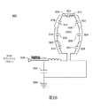
本発明の1つの態様によれば、製品容器からソレノイドポンプを通じて流れる流体の流動状態を監視するシステムが開示される。このシステムは、通電するとソレノイドポンプの1ストロークを発生させるソレノイドコイルを含む少なくとも1つのソレノイドポンプと、少なくとも1つのソレノイドポンプに接続された少なくとも1つの製品容器と、を含み、少なくとも1つのソレノイドポンプは各ストローク中に少なくとも1つの製品容器から流体を吐出し、また、少なくとも1つのソレノイドポンプを通電させるように構成された少なくとも1つのPWMコントローラと、ソレノイドコイルを通る電流フローを検出し、検出電流フローの出力を生成する少なくとも1つの電流センサと、PWMコントローラに命令することによってソレノイドポンプを通る流体の流量を制御し、電流センサからの出力を受け取ることによってソレノイドポンプを通る電流を監視するための制御論理サブシステムと、を含み、制御論理サブシステムは、ソレノイドコイルを通る電流フローの測定値を使用して、ソレノイドポンプのストロークが機能的であるか否かを判定する。 According to one aspect of the present invention, a system for monitoring the flow state of fluid flowing from a product container through a solenoid pump is disclosed. The system includes at least one solenoid pump including a solenoid coil that generates a stroke of the solenoid pump when energized, and at least one product container connected to the at least one solenoid pump, wherein the at least one solenoid pump is At least one PWM controller configured to discharge fluid from at least one product container during each stroke and to energize at least one solenoid pump, and to detect current flow through the solenoid coil and detect current flow At least one current sensor that produces an output of the current, and controls the flow of fluid through the solenoid pump by commanding the PWM controller, and monitors the current through the solenoid pump by receiving the output from the current sensor. Anda control logic subsystem, the control logic subsystem, using measurements of current flow through the solenoid coil, it is determined whether the stroke of the solenoid pump is functional.
本発明のこの態様のいくつかの実施形態は、以下の特徴のうちの1つまたは複数を含んでいてもよい。すなわち、制御論理サブシステムが、少なくともソレノイドコイルを通る電流フローの測定値を使用して、少なくとも1つの製品容器が売切れ状態であると判定する。制御論理サブシステムが、ソレノイドコイルを通る電流フローの測定値を使用して、ソレノイドポンプのストロークが非機能的であるか否かを判定する。制御論理サブシステムが、ソレノイドコイルを通る電流フローの測定値を使用して、ソレノイドポンプのストロークが売切れストロークであるか否かを判定する。制御論理サブシステムが、連続する売切れストロークの閾値回数に達したときに、少なくとも1つの製品容器が売切れ状態であると判定する。少なくとも1つの製品容器がRFIDタグをさらに含み、これが少なくとも1つの製品容器内に残っている流体の量を表す残量表示の値を記憶する。制御論理サブシステムが、ある回数の連続する売切れストロークが判定され、残量値が閾値体積を超えたときに、少なくとも1つの製品容器が売切れ状態であると判定する。 Some embodiments of this aspect of the invention may include one or more of the following features. That is, the control logic subsystem determines that at least one product container is sold out using at least a measurement of current flow through the solenoid coil. The control logic subsystem uses a measurement of current flow through the solenoid coil to determine whether the stroke of the solenoid pump is non-functional. The control logic subsystem uses the measured current flow through the solenoid coil to determine whether the stroke of the solenoid pump is a sold out stroke. The control logic subsystem determines that at least one product container is sold out when a threshold number of consecutive sold-out strokes is reached. The at least one product container further includes an RFID tag that stores a remaining capacity value representing the amount of fluid remaining in the at least one product container. The control logic subsystem determines that at least one product container is sold out when a certain number of consecutive sold out strokes are determined and the remaining value exceeds a threshold volume.
本発明の1つの態様によれば、製品容器からの流体のソレノイドポンプを通る流量を監視する方法が開示される。この方法は、ソレノイドポンプのソレノイドコイルを通電させて、ソレノイドポンプの1ストロークを発生させるステップと、各ストローク中にソレノイドポンプを通じて製品容器からの流体を吐出するステップと、電流センサを使用してソレノイドを通る電流フローを検出し、検出電流フローの出力を生成するステップと、制御論理サブシステムを使用して、ソレノイドポンプを通る電流を監視するステップであって、制御論理サブシステムが電流センサからの検出電流を受け取るステップと、ソレノイドポンプのストロークが機能的か否かを判定するステップと、を含む。 According to one aspect of the invention, a method for monitoring the flow rate of fluid from a product container through a solenoid pump is disclosed. The method includes energizing a solenoid coil of a solenoid pump to generate one stroke of the solenoid pump, discharging fluid from the product container through the solenoid pump during each stroke, and a solenoid using a current sensor. Detecting current flow through and generating an output of the detected current flow, and using a control logic subsystem to monitor current through the solenoid pump, the control logic subsystem from the current sensor Receiving the detected current and determining whether the stroke of the solenoid pump is functional.
本発明のこの態様のいくつかの実施形態は、以下の特徴のうちの1つまたは複数を含んでいてもよい。すなわち、制御論理サブシステムが、少なくともソレノイドコイルを通る電流フローの測定値を使用して、少なくとも1つの製品容器が売切れ状態であると判定する。制御論理サブシステムが、ソレノイドコイルを通る電流フローの測定値を使用して、ソレノイドポンプのストロークが非機能的であるか否かを判定する。制御論理サブシステムが、ソレノイドコイルを通る電流フローの測定値を使用して、ソレノイドポンプのストロークが売切れストロークであるか否かを判定する。制御論理サブシステムが、連続する売切れストロークの閾値回数に到達したときに、少なくとも1つの製品容器が売切れ状態であると判定する。少なくとも1つの製品容器内に残っている流体の量を表す残量表示の値を記憶するRFIDタグを使用して、製品容器に残っている流体の量を測定するステップ。制御論理サブシステムが、ある回数の連続する売切れストロークが判定され、残量表示が閾値体積を超えたときに、製品容器が売切れ状態であると判定する。 Some embodiments of this aspect of the invention may include one or more of the following features. That is, the control logic subsystem determines that at least one product container is sold out using at least a measurement of current flow through the solenoid coil. The control logic subsystem uses a measurement of current flow through the solenoid coil to determine whether the stroke of the solenoid pump is non-functional. The control logic subsystem uses the measured current flow through the solenoid coil to determine whether the stroke of the solenoid pump is a sold out stroke. The control logic subsystem determines that at least one product container is sold out when a threshold number of consecutive sold-out strokes is reached. Measuring the amount of fluid remaining in the product container using an RFID tag that stores a remaining capacity value representative of the amount of fluid remaining in the at least one product container. The control logic subsystem determines that the product container is sold out when a certain number of consecutive sold out strokes are determined and the remaining capacity display exceeds a threshold volume.
本発明の1つの態様によれば、製品容器が売切れ状態であると判定するシステムが開示される。このシステムは、通電するとソレノイドポンプの1ストロークを発生させるソレノイドコイルを含む少なくとも1つのソレノイドポンプと、少なくとも1つのソレノイドポンプに接続された少なくとも1つの製品容器と、を含み、少なくとも1つのソレノイドポンプは各ストローク中に少なくとも1つの製品容器から流体を吐出し、また、少なくとも1つのソレノイドポンプを通電させ、少なくとも1つのソレノイドコイルに印加される電圧を制御するように構成された少なくとも1つのPWMコントローラと、ソレノイドコイルを通る電流フローを検出し、検出電流フローの出力を生成する少なくとも1つの電流センサと、PWMコントローラに命令することによってソレノイドポンプを通る流体の流量を制御し、電流センサからの出力を受け取ることによってポンプを通る電流を監視するための制御論理サブシステムと、を含み、制御論理サブシステムは、少なくともソレノイドコイルを通る電流フローの測定値を使用して、少なくとも1つの製品容器が売切れ状態であると判定する。 In accordance with one aspect of the present invention, a system for determining that a product container is sold out is disclosed. The system includes at least one solenoid pump including a solenoid coil that generates a stroke of the solenoid pump when energized, and at least one product container connected to the at least one solenoid pump, wherein the at least one solenoid pump is At least one PWM controller configured to discharge fluid from at least one product container during each stroke and to energize at least one solenoid pump to control a voltage applied to at least one solenoid coil; At least one current sensor that detects the current flow through the solenoid coil and generates an output of the detected current flow; and controls the flow rate of the fluid through the solenoid pump by commanding the PWM controller, and outputs from the current sensor A control logic subsystem for monitoring current through the pump by scraping, wherein the control logic subsystem uses at least a measurement of current flow through the solenoid coil to sell out at least one product container. It is determined that it is in a state.
本発明のこの態様のいくつかの実施形態は、以下の特徴のうちの1つまたは複数を含んでいてもよい。すなわち、制御論理サブシステムが、電流センサの出力に基づいて、少なくとも1つのソレノイドポンプのストロークが機能的ストロークであったか否かを判定する。制御論理サブシステムが、電流センサの出力に基づいて、少なくとも1つのソレノイドポンプのストロークが売切れストロークであったか否かを判定する。制御論理サブシステムが、連続する売切れストロークの閾値回数に到達したときに、少なくとも1つの製品容器が売切れ状態であると判定する。制御論理サブシステムが、電流センサの出力に基づいて、少なくとも1つのソレノイドポンプのストロークが非機能的ストロークであったか否かを判定する。少なくとも1つの製品容器が、少なくとも1つの製品容器内に残っている流体の量を表す残量表示の値を記憶するRFIDタグをさらに含む。制御論理サブシステムが、連続する売切れストロークのある数が判断され、残量表示が閾値体積を超えたときに、システムが売切れ状態であると判定する。制御論理サブシステムが、PWMコントローラの高周波数デューティサイクルを変化させることによって、電流センサにより測定された電流を制御する。少なくとも1つのソレノイドポンプに、少なくとも1つのPWMコントローラと少なくとも1つの電流センサを介して接続された少なくとも1つの電源。 Some embodiments of this aspect of the invention may include one or more of the following features. That is, the control logic subsystem determines whether the stroke of at least one solenoid pump was a functional stroke based on the output of the current sensor. The control logic subsystem determines whether the stroke of at least one solenoid pump was a sold out stroke based on the output of the current sensor. The control logic subsystem determines that at least one product container is sold out when a threshold number of consecutive sold-out strokes is reached. The control logic subsystem determines whether the stroke of the at least one solenoid pump was a non-functional stroke based on the output of the current sensor. The at least one product container further includes an RFID tag that stores a remaining capacity value representing the amount of fluid remaining in the at least one product container. The control logic subsystem determines that the system is sold out when a certain number of consecutive sold out strokes is determined and the remaining capacity display exceeds a threshold volume. A control logic subsystem controls the current measured by the current sensor by changing the high frequency duty cycle of the PWM controller. At least one power source connected to at least one solenoid pump via at least one PWM controller and at least one current sensor.
本発明の1つの態様によれば、製品注出システムの誤読取(cross−reading)を低減させための方法が開示される。この方法は、製品注出システム内の複数のRFIDタグアセンブリをスキャンするステップと、1つまたは複数のRFIDタグアセンブリが複数のスロット内で読み取られた場合に、RFIDタグアセンブリを評価して製品注出システム内の位置を特定するステップと、フィットメントマップを比較するステップと、受け取った信号強度指示値を比較するステップと、を含む。 According to one aspect of the present invention, a method for reducing cross-reading of a product dispensing system is disclosed. The method includes scanning a plurality of RFID tag assemblies in a product dispensing system and evaluating the RFID tag assembly when one or more RFID tag assemblies are read in multiple slots. Identifying a position in the exit system, comparing the fitment map, and comparing the received signal strength indication value.
本発明の1つの態様によれば、第一の実施例において、流量計は流体を受けるように構成された流体室を含む。ダイアフラムアセンブリは、流体室内の流体が変位するたびに変位するように構成される。トランスデューサアセンブリはダイアフラムアセンブリの変位を監視して、少なくともひとつには、流体室内で変位した流体の量に基づいて、信号を発生するように構成される。 According to one aspect of the present invention, in a first embodiment, the flow meter includes a fluid chamber configured to receive fluid. The diaphragm assembly is configured to displace whenever the fluid in the fluid chamber is displaced. The transducer assembly is configured to monitor the displacement of the diaphragm assembly and generate a signal based at least in part on the amount of fluid displaced within the fluid chamber.
本発明のこの態様のいくつかの実施形態は、以下の特徴のうちの1つまたは複数を含んでいてもよい。すなわち、トランスデューサアセンブリが、連結アセンブリによってダイアフラムアセンブリに連結された線形可変差動変圧器を含むこと、トランスデューサアセンブリが針/磁石カートリッジアセンブリを含むこと、トランスデューサアセンブリが磁気コイルアセンブリを含むこと、トランスデューサアセンブリがホール効果センサアセンブリを含むこと、トランスデューサアセンブリが圧電ブザー素子を含むこと、トランスデューサアセンブリが圧電シート素子を含むこと、トランスデューサアセンブリがオーディオスピーカアセンブリを含むこと、トランスデューサアセンブリが加速度計アセンブリを含むこと、トランスデューサアセンブリがマイクロフォンアセンブリを含むこと、および/またはトランスデューサアセンブリが光学変位アセンブリを含むこと。 Some embodiments of this aspect of the invention may include one or more of the following features. That is, the transducer assembly includes a linear variable differential transformer coupled to the diaphragm assembly by a coupling assembly, the transducer assembly includes a needle / magnet cartridge assembly, the transducer assembly includes a magnetic coil assembly, the transducer assembly Including a Hall effect sensor assembly, the transducer assembly including a piezoelectric buzzer element, the transducer assembly including a piezoelectric sheet element, the transducer assembly including an audio speaker assembly, the transducer assembly including an accelerometer assembly, the transducer assembly Includes a microphone assembly and / or the transducer assembly is optical To include a place assembly.
本発明の他の態様によれば、製品容器が空であることを判定する方法が開示される。この方法は、ポンプアセンブリを通電させるステップと、製品容器からマイクロ原料を吐出させるステップと、容量性プレートを変位距離だけ変位させるステップと、コンデンサのキャパシタンスを測定するステップと、キャパシタンスの測定値から変位距離を計算するステップと、製品容器が空か否かを判定するステップと、を含む。 According to another aspect of the invention, a method for determining that a product container is empty is disclosed. The method includes energizing a pump assembly, discharging micro raw material from a product container, displacing a capacitive plate by a displacement distance, measuring a capacitance of the capacitor, and displacing the measured capacitance value. Calculating a distance and determining whether the product container is empty.
本発明の他の態様によれば、製品容器が空であることを判定する方法が開示される。この方法は、ポンプアセンブリを通電させるステップと、製品容器からマイクロ原料を吐出させることによって、ダイアフラムアセンブリを変位距離だけ変位させるステップと、トランスデューサアセンブリを使用して変位距離を測定するステップと、少なくともひとつには、製品容器から吐出されたマイクロ原料の量に基づいて信号を生成するトランスデューサアセンブリを使用するステップと、その信号を使用して、製品容器が空か否かを判定するステップと、を含む。 According to another aspect of the invention, a method for determining that a product container is empty is disclosed. The method includes at least one of energizing a pump assembly, displacing the diaphragm assembly by a displacement distance by discharging micro raw material from the product container, and measuring the displacement distance using the transducer assembly. Using a transducer assembly that generates a signal based on the amount of micro raw material dispensed from the product container, and using the signal to determine whether the product container is empty. .
本発明の他の態様によれば、製品注出システムのためのブラケットが開示される。このブラケットは、製品注出システムのドアにある少なくとも1つのバーコードリーダと位置合わせされるように構成された複数のタブを含む。 In accordance with another aspect of the present invention, a bracket for a product dispensing system is disclosed. The bracket includes a plurality of tabs configured to be aligned with at least one barcode reader on a door of the product dispensing system.
本発明の上記の態様は排他的とされるのではなく、本発明の他の特徴、態様、利点は、付属の特許請求の範囲および添付の図面とともに読めば、当業者にとって容易に明らかとなるであろう。 The above aspects of the invention are not intended to be exclusive, and other features, aspects, and advantages of the invention will be readily apparent to those skilled in the art when read in conjunction with the appended claims and accompanying drawings. Will.
本発明の上記およびその他の特徴と利点は、以下の詳細な説明を次のような図面と併せて読むことにより、さらによく理解されるであろう。 These and other features and advantages of the present invention will be better understood when the following detailed description is read in conjunction with the following drawings, in which:
異なる図中の同様の参照記号は同様の要素を示す。 Like reference symbols in the different drawings indicate like elements.
本明細書では、製品注出システムを説明する。このシステムは、1つまたは複数のモジュール式構成部品を含み、これは「サブシステム」とも呼ばれる。本明細書では例示的システムを各種の実施形態で説明するが、製品注出システムは説明されるサブシステムのうちの1つまたは複数を含んでいてもよく、製品注出システムは説明されるサブシステムのうちの1つまたは複数のみに限定されない。それゆえ、いくつかの実施形態において、製品注出システムには追加のサブシステムを使用してもよい。 In this specification, a product dispensing system will be described. The system includes one or more modular components, also referred to as “subsystems”. Although the exemplary system is described herein in various embodiments, the product dispensing system may include one or more of the described subsystems, and the product dispensing system is described sub It is not limited to just one or more of the systems. Thus, in some embodiments, additional subsystems may be used for the product dispensing system.
以下の開示は、各種の原料を混合し、加工して、ある製品を生成することを可能にする様々な電気的構成部品、機械的構成部品、電気機械的構成部品、ソフトウェアプロセス(すなわち、「サブシステム」)の相互作用と協働を説明する。このような製品の例には、牛乳ベースの製品(たとえば、ミルクシェイク、フロート、モルト、フラッペ)、コーヒーベースの製品(たとえば、コーヒー、カプチーノ、エスプレッソ)、ソーダベースの製品(たとえば、フロート、フルーツジュースのソーダ割り)、茶葉ベースの製品(たとえば、アイスティー、スイートティー、ホットティー)、水ベースの製品(たとえば、天然水、フレーバ付天然水、ビタミン入り天然水、高濃度電解質含有飲料、高濃度炭水化物含有飲料等)、固体ベースの製品(たとえば、トレイルミックス、グラノーラベースの製品、ミックスナッツ、シリアル製品、雑穀製品)、医療用製品(たとえば、不溶融性医薬品、注入可能医薬品、体内摂取可能薬剤、透析液)、アルコールベースの製品(たとえば、ミックスドリンク、ワインスプリッツァ、ソーダベースのアルコール飲料、水ベースのアルコール飲料、フレーバ「ショット」入りビール)、工業用製品(たとえば、溶剤、塗料、潤滑剤、染色剤等)、健康/美容補助製品(たとえば、シャンプー、化粧品、石鹸、ヘアコンディショナ、整肌剤、局所軟膏)が含まれていてもよいが、これらに限定されない。 The following disclosure describes various electrical components, mechanical components, electromechanical components, software processes (i.e., "" that allow various ingredients to be mixed and processed to produce a product. Explain the interaction and collaboration of subsystems)). Examples of such products include milk-based products (eg milk shakes, floats, malts, frappes), coffee-based products (eg coffee, cappuccino, espresso), soda-based products (eg floats, fruits Juice soda), tea-based products (eg iced tea, sweet tea, hot tea), water-based products (eg natural water, natural water with flavor, natural water with vitamins, high-concentration electrolyte-containing beverages, high Concentrated carbohydrate-containing beverages, etc.), solid based products (eg trail mix, granola based products, mixed nuts, cereal products, millet products), medical products (eg infusible drugs, injectable drugs, ingestible Drugs, dialysate), alcohol-based products (eg Drinks, wine spritzers, soda-based alcoholic beverages, water-based alcoholic beverages, flavored “shot” beer), industrial products (eg solvents, paints, lubricants, dyes, etc.), health / beauty supplements (For example, shampoo, cosmetics, soap, hair conditioner, skin conditioner, topical ointment) may be included, but is not limited thereto.
製品は、1種または複数種の「原料」を使用して生成してもよい。原料は、1種または複数種の流体、粉末、固体または気体を含んでいてもよい。流体、粉末、固体および/または気体は、加工と注出の文脈中、還元または希釈されてもよい。製品は、流体、固体、粉末または気体であってもよい。 The product may be produced using one or more “raw materials”. The raw material may contain one or more fluids, powders, solids or gases. Fluids, powders, solids and / or gases may be reduced or diluted in the context of processing and dispensing. The product may be fluid, solid, powder or gas.
各種の原料は、「マクロ原料」、「マイクロ原料」、または「大量マイクロ原料」と呼ばれてもよい。使用される原料の1種または複数は、筐体、すなわち製品注出機の一部の中に収容されていてもよい。しかしながら、原料の1種または複数は機械の外部で貯蔵または生成されてもよい。たとえば、いくつかの実施形態において、大量に使用される(異なる量の)水またはその他の原料は、機械の外部で貯蔵されてもよく(たとえば、いくつかの実施形態において、高果糖コーンシロップは機械の外部で貯蔵されてもよい)、その一方で、他の原料、たとえば粉末状原料、濃縮原料、栄養補助成分、医薬品および/またはガスシリンダは機械そのものの中に貯蔵されてもよい。 The various raw materials may be referred to as “macro raw materials”, “micro raw materials”, or “mass micro raw materials”. One or more of the raw materials used may be housed in a housing, i.e. part of the product dispenser. However, one or more of the raw materials may be stored or produced outside the machine. For example, in some embodiments, large amounts (different amounts) of water or other ingredients may be stored outside the machine (eg, in some embodiments, high fructose corn syrup is Other ingredients, such as powdered ingredients, concentrated ingredients, nutritional supplements, pharmaceuticals and / or gas cylinders, may be stored within the machine itself, which may be stored outside the machine.
上記の電気的構成部品、機械的構成部品、電気機械的構成部品、ソフトウェアプロセスの様々な組み合わせを以下に説明する。以下で、たとえば飲料と医薬品(たとえば、透析液)の各種のサブシステムを使用した生成を開示する組み合わせについて説明するが、これは本願の限定とすることは意図されず、むしろ、サブシステムが協働して製品を生成/注出できる方法の例示的実施形態とする。具体的には、電気的構成部品、機械的構成部品、電気機械的構成部品、ソフトウェアプロセス(その各々を以下により詳しく説明する)を使用して、上記の製品またはそれらと類似のあらゆるその他の製品のいずれを生成してもよい。 Various combinations of the above electrical components, mechanical components, electromechanical components, and software processes are described below. In the following, for example, combinations that disclose production using various subsystems of beverages and pharmaceuticals (eg, dialysate) are described, but this is not intended to be a limitation of the present application; rather, the subsystems cooperate. It is an exemplary embodiment of a method that can work to produce / dispens a product. Specifically, using electrical components, mechanical components, electromechanical components, software processes (each of which is described in more detail below), the above products or any other product similar to them Either of these may be generated.
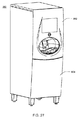
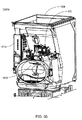
図1を参照すると、加工システム10の概観が示されており、これは複数のサブシステム、すなわち貯蔵サブシステム12と、制御論理サブシステム14と、大量原料サブシステム16と、マイクロ原料サブシステム18と、配管/制御サブシステム20と、ユーザインタフェースサブシステム22と、ノズル24と、を含むように描かれている。上記のサブシステム12、14、16、18、20、22の各々を以下により詳しく説明する。
Referring to FIG. 1, an overview of a
加工システム10の使用中、使用者26はユーザインタフェースサブシステム22を使用して、(容器30の中に)注出すべき特定の製品28を選択してもよい。使用者26は、ユーザインタフェースサブシステム22を介して、そのような製品の中に含めるべき1つまたは複数のオプションを選択してもよい。たとえば、オプションには、1種または複数種の原料の添加が含まれていてもよいが、これに限定されない。1つの例示的実施形態において、このシステムは飲料を注出するためのシステムである。この実施形態では、使用者は、飲料に添加すべき各種のフレーバリング(たとえば、レモンフレーバリング、ライムフレーバリング、チョコレートフレーバリング、バニラフレーバリングを含むが、これらに限定されない)、飲料への1種または複数種の栄養補助成分(たとえば、ビタミンA、ビタミンC、ビタミンD、ビタミンE、ビタミンB6、ビタミンB12および亜鉛を含むが、これらに限定されない)の添加、飲料への1種または複数種の食品(たとえば、アイスクリーム、ヨーグルト)の添加を選択できる。
During use of the
使用者26がユーザインタフェースサブシステム22を介して適当な選択を行うと、ユーザインタフェースサブシステム22は、適当なデータ信号を(データバス32を介して)制御論理サブシステム14に送信できる。制御論理サブシステム14は、これらの信号を処理でき、ストレージサブシステム12に保持された複数のレシピ36から選択された1つまたは複数のレシピを(データバス34を介して)読み出すことができる。「レシピ」という用語は、要求された製品を加工/生成するための説明を指す。制御論理サブシステム14は、ストレージサブシステム12からレシピを読み出すと、そのレシピを処理して、適当な制御信号を(データバス38を介して)、たとえば大量原料サブシステム16と、マイクロ原料サブシステム18(および、いくつかの実施形態においては、加工に関するマイクロ原料についての説明の中に含まれているかもしれない、図示されていない大量マイクロ原料。これらの大量マイクロ原料の注出には、いくつかの実施形態において、マイクロ原料アセンブリの代わりのアセンブリを使用してもよい。)と、配管/制御サブシステム20に供給することができ、その結果、製品28が生成され(、これが容器30に注出され)る。
Once the
図2も参照すると、制御論理サブシステム14の概略図が示されている。制御論理サブシステム14は、マイクプロセッサ100(たとえば、California、Santa ClaraのIntel Corporationが製造するARM (商標)マイクプロセッサ)と、不揮発性メモリ(たとえば、リードオンリメモリ102)と、揮発性メモリ(たとえば、ランダムアクセスメモリ104)と、を含んでいてもよく、その各々は1つまたは複数のデータ/システムバス106、108を介して相互接続されていてもよい。上述のように、ユーザインタフェースサブシステム22がデータバス32を介して制御論理サブシステム14に連結されていてもよい。
Referring also to FIG. 2, a schematic diagram of the
制御論理サブシステム14はまた、たとえばアナログオーディオ信号をスピーカ112に供給するオーディオサブシステム110を含んでいてもよく、これは、加工システム10に組み込まれていてもよい。オーディオサブシステム110は、データ/システムバス114を介してマイクプロセッサ100に連結されていてもよい。
The
制御論理サブシステム14はオペレーティングシステムを実行してもよく、その例には、Microsoft Windows CE(商標)、Redhat Linux(商標)、Palm OS(商標)またはデバイス特定(すなわち、カスタム)オペレーティングシステムが含まれていてもよいが、これらに限定されない。
The
ストレージサブシステム12に保存されていてもよい上記のオペレーティングシステムの命令セットとサブルーチンは、制御論理サブシステム14に組み込まれた1つまたは複数のプロセッサ(たとえば、マイクプロセッサ100)および1つまたは複数のメモリ構成(たとえば、リードオンリメモリ102および/またはランダムアクセスメモリ104)によって実行されてもよい。
The operating system instruction set and subroutines that may be stored in the
ストレージサブシステム12には、たとえば、たとえばハードディスクドライブ、ソリッドステートドライブ、光ドライブ、ランダムアクセスメモリ(RAM)、リードオンリメモリ(ROM)、CF(すなわち、コンパクトフラッシュ)カード、SD(すなわち、セキュアデジタル)カード、SmartMediaカード、Memory StickおよびMultiMediaカードが含まれていてもよい。
上述のように、ストレージサブシステム12は、データバス34を介して制御論理サブシステム14に連結されていてもよい。制御論理サブシステム14はまた、マイクプロセッサ100によって供給された信号をストレージシステム12が使用可能なフォーマットに変換するためのストレージコントローラ116(破線で示される)を含んでいてもよい。さらに、ストレージコントローラ116は、ストレージサブシステム12によって供給された信号をマイクロプロセッサ100が使用可能なフォーマットに変換できる。
As described above, the
いくつかの実施形態において、イーサネット接続もまた含まれる。 In some embodiments, an Ethernet connection is also included.
上述のように、大量原料サブシステム(本明細書では「マクロ原料」とも呼ぶ)16と、マイクロ原料サブシステム18および/または配管/制御サブシステム20がデータバス38を介して制御論理サブシステム14に連結されていてもよい。制御論理サブシステム14は、マイクロプロセッサ100によって供給された信号を大量原料サブシステム16、マイクロ原料サブシステム18および/または配管/制御サブシステム20が使用可能なフォーマットに変換するためのバスインタフェース118(破線で示される)を含んでいてもよい。さらに、バスインタフェース118は、大量原料サブシステム16、マイクロ原料サブシステム18および/または配管/制御サブシステム20により供給された信号をマイクロプロセッサ100が使用可能なフォーマットに変換してもよい。
As described above, the bulk feed subsystem (also referred to herein as “macro feed”) 16 and the
後により詳しく説明するように、制御論理サブシステム14は、1つまたは複数の制御プロセス120(たとえば、有限ステートマシンプロセス(FSMプロセス122)、仮想マシンプロセス124、仮想マニホルドプロセス126等)を実行してもよく、これは加工システム10の動作を制御しうる。ストレージサブシステム12に保存されていてもよい制御プロセス120の命令セットとサブルーチンは、制御論理サブシステム14に組み込まれた1つまたは複数のプロセッサ(たとえば、マイクロプロセッサ100)と1つまたは複数のメモリ構成(たとえば、リードオンリメモリ102および/またはランダムアクセスメモリ104)により実行されてもよい。
As will be described in more detail later, the
図3も参照すると、大量原料サブシステム16と配管/制御サブシステム20の概略図が示されている。大量原料サブシステム16は、飲料28を生成する際に急速度で使用される消耗品を格納する容器を含んでいてもよい。たとえば、大量原料サブシステム16は、炭酸供給部150と、水供給部152と、高果糖コーンシロップ供給部154と、を含んでいてもよい。いくつかの実施形態において、大量原料は他のサブシステムの近隣に位置付けられる。炭酸供給部150の例には、圧縮炭酸ガスのタンク(図示せず)が含まれていてもよいが、これに限定されない。水供給部152の例には、上水道(図示せず)、蒸留水供給部、ろ過水供給部、逆浸透圧(RO)水供給部またはその他の所望の水供給部が含まれていてもよいが、これらに限定されない。高果糖コーンシロップ供給部154の例には、高濃度高果糖コーンシロップの1つまたは複数のタンク(図示せず)または高果糖コーンシロップの1つまたは複数のバッグインボックスパッケージが含まれていてもよいが、これらに限定されない。
Referring also to FIG. 3, a schematic diagram of the
大量原料サブシステム16は、炭酸ガス(炭酸供給部150により供給される)と水(水供給部152により供給される)から炭酸水を生成するためのカーボネータ156を含んでいてもよい。炭酸水158と水160と高果糖コーンシロップ162が冷却板アセンブリ163に供給されてもよい(たとえば、製品を冷やすことが望ましいかもしれない実施形態の場合。いくつかの実施形態において、冷却板アセンブリは、注出システムの一部として含められず、または迂回されてもよい)。冷却板アセンブリ163は、炭酸水158、水160、高果糖コーンシロップ162を所望の提供温度(たとえば、40°F)まで冷却するように設計されていてもよい。
The mass
1枚の冷却板163で炭酸水158、水160、高果糖コーンシロップ162を冷却するように示されているが、これは例示のためにすぎず、他の構成も可能であるため、本願の限定とすることは意図されていない。たとえば、炭酸水158、水160、高果糖コーンシロップ162の各々を冷却するのに個別の冷却板を使用してもよい。冷却後、冷却された炭酸水164、冷却された水166、冷却された高加藤コーンシロップ168が配管/制御サブシステム20に供給されてもよい。また別の実施形態では、冷却板は含まれていなくてもよい。いくつかの実施形態において、少なくとも1枚の加熱板だけが含まれていてもよい。
Although a single cooling plate 163 is shown to cool
配管は図の順序を有するように描かれているが、いくつかの実施形態において、この順序は使用されない。たとえば、本明細書で説明する流量制御モジュールは別の順序、すなわち、流量測定装置、バイナリバルブ、次に可変ラインインピーダンスの順で構成されてもよい。 Although the piping is depicted as having the order shown, in some embodiments, this order is not used. For example, the flow control modules described herein may be configured in a different order: flow measurement device, binary valve, then variable line impedance.
説明を目的として、システムは以下に、このシステムを使用して製品としてソフトドリンクを注出することに関して説明され、すなわち、説明されるマクロ原料/大量原料に、高果糖コーンシロップ、炭酸水、水が含まれる。しかしながら、注出システムの他の実施形態では、マクロ原料そのものおよびマクロ原料の数は異なっていてもよい。 For illustrative purposes, the system will be described below with respect to dispensing soft drinks as products using this system, ie, high fructose corn syrup, carbonated water, water to the described macro / mass ingredients. Is included. However, in other embodiments of the dispensing system, the macro raw material itself and the number of macro raw materials may be different.
例示を目的として、配管/制御サブシステム20は、3つの流量制御モジュール170、172、174を含むように示されている。流量制御モジュール170、172、174は一般に、大量原料の量および/または流速を制御できる。流量制御モジュール170、172、174は各々、流量測定装置(たとえば、流量測定装置176、178、180)を含んでいてもよく、これらは(それぞれ)冷却された炭酸水164、冷却された水166、冷却された高果糖コーンシップ168の量を測定する。流量測定装置176、178、180は、(それぞれ)フィードバック信号182、184、186を(それぞれ)フィードバックコントローラシステム188、190、192に供給できる。
For illustrative purposes, the piping /
フィードバックコントローラシステム188、190、192(これについては後でより詳しく説明する)は、流量フィードバック信号182、184、186を所望の流量(それぞれ、冷却された炭酸水164、冷却された水166、冷却された高果糖コーンシロップ168の各々に関して設定される)と比較できる。流量フィードバック信号182、184、186を処理すると、(それぞれ)フィードバックコントローラシステム188、190、192は、(それぞれ)流量制御信号194、196、198を生成でき、これらは(それぞれ)可変ラインインピーダンス200、202、204に供給されうる。可変ラインインピーダンス200、202、204の例は、米国特許第5,755,683号明細書(代理人整理番号B13)と米国特許出願公開第2007/0085049号明細書(代理人整理番号E66)において開示され、特許請求されている。可変ラインインピーダンス200、202、204は、(それぞれ)ライン218、220、222を通過する冷却された炭酸水164、冷却された水166、冷却された高加藤コーンシロップ168の流量を調整でき、これらはノズル24と(それに続いて)容器30に供給される。しかしながら、可変ラインインピーダンスのまた別の実施形態が本明細書に記載されている。
ライン218、220、222はさらに、(それぞれ)バイナリバルブ212、214、216を含んでいてもよく、これらは流体流が望まれない/要求されない時(たとえば、出荷、メンテナンス手順、ダウンタイム中)はライン218、220、222に流体が流れないようにする。
1つの実施形態において、バイナリバルブ212、214、216はソレノイド式バイナリバルブを含んでいてもよい。しかしながら、他の実施形態においては、バイナリバルブは当業界で知られているどのバイナリバルブであってもよく、これは、いずれかの手段で作動されるバイナリバルブを含むが、これに限定されない。これに加えて、バイナリバルブ212、214、216は、加工システム10が製品を注出していないときには必ず、ライン218、220、222に流体が流れないようにするように構成されていてもよい。さらに、バイナリバルブ212、214、216の機能は、可変ラインインピーダンス200、202、204を介して、可変ラインインピーダンス200、202、204を完全に閉じ、それゆえライン218、220、222に流体が流ないようにすることによって、実現されてもよい。
In one embodiment, the
前述のように、図3は配管/制御サブシステム20の例示的な図を提供しているにすぎない。したがって、配管/制御サブシステム20が示されている方法は、他の構成も可能てあるため、本願の限定とすることは意図されない。たとえば、フィードバックコントローラシステム182、184、186の機能の一部または全部は、制御論理サブシステム14に組み込まれてもよい。また、流量制御モジュール170、172、174に関して、構成部品の配列構成は図3で例示のために示されているにすぎない。それゆえ、図の配列構成は単に例示的実施形態としての役割を果たす。しかしながら、他の実施形態において、構成部品は異なる配列で配置されてもよい。
As mentioned above, FIG. 3 only provides an exemplary diagram of the piping /
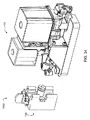
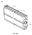
図4も参照すると、マイクロ原料サブシステム18と配管/制御サブシステム20の概略的上面図が示されている。マイクロ原料サブシステム18は製品モジュールアセンブリ250を含んでいてもよく、これは1つまたは複数の製品容器252、254、256、258と釈放可能に係合するように構成されていてもよく、これらは製品28の生成ときに使用されるマイクロ原料を保持するように構成されていてもよい。マイクロ原料は、製品の生成において使用される基質である。このようなマイクロ原料/基質の例には、ソフトドリンクフレーバリングの第一の部分、ソフトドリンクフレーバリングの第二の部分、コーヒーフレーバリング、栄養補助成分、医薬品が含まれていてもよいが、これらに限定されず、流体、粉末、または固体であってもよい。しかしながら、例示のために、以下の説明は流体のマイクロ原料に関する。いくつかの実施形態において、マイクロ原料は粉末または固体である。マイクロ原料が粉末である場合、システムは、粉末を計量し、および/または粉末を還元するための追加のサブシステムを含んでいてもよい(しかし、以下の例で説明するように、マイクロ原料が粉末である場合、粉末は製品を混合する方法の一部として還元されてもよい、すなわち、ソフトウェアマニホルド)。
Referring also to FIG. 4, a schematic top view of the micro
製品モジュールアセンブリ250は、複数の製品容器252、254、256、258と釈放可能に係合するように構成された複数のスロットアセンブリ260、262、264、266を含んでいてもよい。この特定の例において、製品モジュールアセンブリ250は4つのスロットアセンブリ(すなわち、スロット260、262、264、266)を含むように示されており、したがって、4連型製品モジュールアセンブリと呼ぶことができる。製品容器252、254、256、258を製品モジュールアセンブリ250の中に位置付ける際、製品容器(たとえば、製品容器254)をスロットアセンブリ(たとえば、スロットアセンブリ262)に矢印268の方向にスライドさせて入れてもよい。本願で示されているように、この例示的実施形態においては「4連型製品モジュール」アセンブリが説明されているが、他の実施形態では、1つのモジュールアセンブリ内に収容する製品はこれより多くても、少なくてもよい。注出システムにより注出される製品に応じて、製品容器の数は異なってもよい。それゆえ、いずれかのモジュールアセンブリ内に収容される製品の数は、用途ごとに異なっていてもよく、システムの所望の特徴、たとえば、ただしこれらに限定されないが、システムの効率、必要性、および/または機能を満足させるように選択されてもよい。
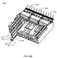
例示のために、製品モジュールアセンブリ250の各スロットアセンブリは、ポンプアセンブリを含むように示されている。たとえば、スロットアセンブリ252は、ポンプアセンブリ270を含むように示され、スロットアセンブリ262はポンプアセンブリ272を含むように示され、スロットアセンブリ264はポンプアセンブリ274を含むように示され、スロットアセンブリ266はポンプアセンブリ276を含むように示される。
For illustration, each slot assembly of
入口ポートがポンプアセンブリ270、272、274、276の各々に連結され、製品容器内に含められる製品開口部と釈放可能に係合してもよい。たとえば、ポンプアセンブリ272は、製品容器254内に含められる容器開口部280と釈放可能に係合するように構成された入口ポート278を含むように示されている。入口ポート278および/または製品開口部280は、1つまたは複数のシーリングアセンブリ(図示せず)、たとえば1つまたは複数のOリングまたはルア継手を含み、漏出防止密閉状態としやすくなっていてもよい。各ポンプアセンブリに連結された入口ポート(たとえば、入口ポート278)は、剛性の「パイプ様」材料で構成されていてもよく、または、柔軟な「チューブ様」材料で構成されていてもよい。
An inlet port may be coupled to each of the
1つまたは複数のポンプアセンブリ270、272、274、276の例には、ポンプアセンブリ270、272、274、276の1つまたは複数が通電するたびに、校正に基づく予想量の流体を供給するソレノイドピストンポンプアセンブリが含まれていてもよいが、これに限定されない。1つの実施形態において、このようなポンプは、イタリア・パビア(Pavia)のULKA Costruzioni Elettromeccaniche S.p.A.から入手可能である。たとえば、ポンプアセンブリ(たとえば、ポンプアセンブリ274)がデータバス38を介して制御論理サブシステム14により通電されるたびに、ポンプアセンブリは製品容器256内に収容された流体マイクロ原料を約30μL供給してもよい(しかしながら、供給されるフレーバリングの量は校正に基づいて異なっていてもよい)。再び、例示のためにのみ、マイクロ原料は説明のこの部分では流体である。「校正に基づく」という用語は、ポンプアセンブリおよび/またはその個々のポンプの校正を通じて確認可能な体積に関する、またはその他の情報および/または特徴を指す。
Examples of one or
ポンプアセンブリ270、272、274、276のその他の例と各種のポンピング技術は、米国特許第4,808,161号明細書(代理人整理番号A38)、米国特許第4,826,482号明細書(代理人整理番号A43)、米国特許第4,976,162号明細書(代理人整理番号A52)、米国特許第5,088,515号明細書(代理人整理番号A49)、米国特許第5,350,357号明細書(代理人整理番号147)に記載されており、これらすべての特許の全文を参照によって本願に援用する。いくつかの実施形態において、ポンプアセンブリは図54〜55に示されるような膜ポンプであってもよい。いくつかの実施形態において、ポンプアセンブリは、米国特許第5,421,823号明細書(代理人整理番号158)に記載されているポンプアセンブリのいずれであってもよく、またそのようなポンプ技術のいずれを使用してもよく、同特許の全文を参照によって本願に援用する。
Other examples of
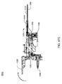
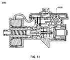
上述の参考文献は、流体の吐出に使用可能な空気圧作動式の膜型ポンプの非限定的な例を説明している。空気圧作動式の膜型ポンプアセンブリは、1つまたは複数の理由によって有利でありえ、これには、多数のデューティサイクルにわたって、ある量、たとえばマイクロリットル単位の量の各種の組成の流体を確実かつ正確に送達できること、および/または空気圧作動式ポンプには、たとえば炭酸源からの空気動力を使用できるため、必要な電力が少なくて済むことが含まれるが、これらに限定されない。これに加えて、膜型ポンプは、表面がシール材に関して移動することになるような動的シールを不要とすることができる。ULKAの製品のような振動ポンプには一般に、動的弾力シールの使用が必要となり、これは時間が経つと、たとえば特定の種類の流体への曝露および/または摩耗が発生した後に故障することがある。いくつかの実施形態において、空気圧作動式の膜型ポンプは、他のポンプより信頼性が高く、より費用対効果が高く、より校正しやすいかもしれない。これらはまた、発生するノイズが他のポンプより少なく、発熱が小さく、消費電力が少ないかもしれない。膜型ポンプの非限定的な例を図54に示す。 The above references describe non-limiting examples of pneumatically actuated membrane pumps that can be used to discharge fluid. Pneumatically actuated membrane pump assemblies can be advantageous for one or more reasons, including ensuring reliable and accurate flow of fluids of various compositions, such as microliter quantities, over a number of duty cycles. And / or pneumatically operated pumps may include, but are not limited to, requiring less power because, for example, pneumatic power from a carbonic acid source may be used. In addition, the membrane pump can eliminate the need for dynamic sealing such that the surface will move relative to the sealing material. Vibration pumps, such as ULKA products, generally require the use of dynamic resilient seals, which can fail over time, for example after exposure to certain types of fluids and / or wear. is there. In some embodiments, pneumatically actuated membrane pumps may be more reliable, more cost effective, and easier to calibrate than other pumps. They may also generate less noise than other pumps, generate less heat, and consume less power. A non-limiting example of a membrane pump is shown in FIG.
図54〜55に示される膜型ポンプアセンブリ2900の各種の実施形態は空洞を含み、これは図54では2942で、ポンプ室と呼んでもよく、図55では2944で、制御流体室と呼んでもよい。空洞はダイアフラム2940を含み、これは空洞を2つの室、すなわちポンプ室2942と容量室(volume chamber)2944に分離する。
Various embodiments of the
ここで図54を参照すると、例示的な膜型ポンプアセンブリ2900の概略図が示されている。この実施形態において、膜型ポンプアセンブリ2900は、膜、すなわちダイアフラム2940と、ポンプ室2942と、制御流体室2944(図55において最もよく見える)と、3ポート切替バルブ2910と、逆止弁2920と2930と、を含む。いくつかの実施形態において、ポンプ室2942の容量は約20マイクロリットル〜約500マイクロリットルの範囲であってもよい。ある例示的実施形態において、ポンプ室2942の容量は約30マイクロリットル〜約250マイクロリットルの範囲であってもよい。他の例示的実施形態において、ポンプ室2942の容量は約40マイクロリットル〜約100マイクロリットルの範囲であってもよい。
Referring now to FIG. 54, a schematic diagram of an exemplary
切替バルブ2910は、ポンプ制御チャネル2958を切替バルブ流体チャネル2954または切替バルブ流体チャネル2956のいずれかと流体連通させるように動作してもよい。非限定的な実施形態において、切替バルブ2910は電磁力で動作するソレノイドバルブであってもよく、制御ライン2912を介した電気信号入力を受けて動作する。他の非限定的な実施形態において、切替バルブ2910は、空気圧または油圧式膜型弁であってもよく、空気圧または油圧信号入力を受けて動作する。また別の実施形態において、切替バルブ2910は、シリンダ内で流体により、空気圧により、機械的に、または電気機械的に動作するピストンであってもよい。より一般的には、ポンプアセンブリ2900用として他のあらゆる種類のバルブを想定でき、バルブが切替バルブの流体チャネル2954と切替バルブの流体チャネル2956の間でポンプ制御チャネル2958との流体連通を切り替えられることが好ましい。
The switching
いくつかの実施形態において、切替バルブの流体チャネル2954は、流体陽圧源(空気圧でも油圧でもよい)に連絡する。必要な流体圧力の量は1つまたは複数の要素に依存する可能性があり、これには、ダイアフラム2940の引張強度と弾力性、吐出される流体の濃度および/または粘性、流体内に溶解する固体の溶解度、および/またはポンプアセンブリ2900内の流体チャネルとポートの長さと大きさが含まれるが、これらに限定されない。各種の実施形態において、流体圧力源は約15psi〜約250psiの範囲であってもよい。ある例示的実施形態において、流体圧力源は約60psi〜約100psiの範囲であってもよい。他の例示的実施形態において、流体圧力源は約70psi〜約80psiの範囲であってもよい。前述のように、注出システムのいくつかの実施形態は炭酸飲料を生成でき、それゆえ原料として炭酸水を使用してもよい。これらの実施形態では、炭酸飲料を生成するために使用されるCO2の気体圧力は約75psiであることが多く、いくつかの実施形態では、同じ気体圧力源をより低圧に調整して、飲料注出機の中で少量の流体を吐出するための膜型ポンプの駆動にも使用してよい。
In some embodiments, the switching
制御ライン2912を介して供給される適当な信号に応答して、バルブ2910は切替バルブの流体チャネル2954をポンプ制御チャネル2958と流体連通させることができる。流体陽圧はそれゆえ、ダイアフラム2940に伝えられ、それがポンプ室2942内の流体をポンプ出口チャネル2950から押し出すことができる。逆止弁2930によって、吐出された流体がポンプ室2942から入口チャネル2952を通って流出することが確実に防止される。
In response to an appropriate signal supplied via
切替バルブ2910は制御ライン2912を介して、ポンプ制御チャネル2958を切替バルブの流体チャネル2956と流体連通させることができ、これによって、ダイアフラム2940はポンプ室2942の壁に到達しうる(図54に示される)。ある実施形態において、切替バルブの流体チャネル2956は真空源と連絡していてもよく、これはポンプ制御チャネル2958と連通すると、ダイアフラム2940を退縮させることができ、ポンプ制御室2944の容積を小さくして、ポンプ室2942の容積を増大させる。ダイアフラム2940の退縮によって、流体はポンプ入口チャネル2952を介してポンプ室2942の中に引き込まれる。逆止弁2920により、吐出された流体が出口チャネル2950を介してポンプ室2942の中へと逆流するのが防止される。
The switching
ある実施形態において、ダイアフラム2940は半剛性のばね様材料で構成されていてもよく、それによってダイアフラムは湾曲または回転楕円形状を保持する傾向を示し、カップ形状のダイアフラム型ばねとして機能する。たとえば、ダイアフラム2940は、少なくとも部分的に薄い金属シートから構成され、またはスタンピング加工されてもよく、使用可能な金属には、高炭素ばね鋼、ニッケル銀、高ニッケル合金、ステンレススチール、チタン合金、ベリリウム銅、およびその他が含まれていてもよいが、これらに限定されない。ポンプアセンブリ2900は、ダイアフラム2940の凸面がポンプ制御室2944および/またはポンプ制御チャネル2958に面するように構成されてもよい。それゆえ、ダイアフラム2940はポンプ室2942の表面に押し当てられた後に退縮しようとする固有の傾向を有しうる。この状況では、切替バルブの流体チャネル2956は、周囲(大気)圧力と連絡していてもよく、それによってダイアフラム2940は自動的に退縮して、ポンプ入口チャネル2952を介してポンプ室2942に流体を引き込むことができる。いくつかの実施形態において、ばね様ダイアフラムの凹部が、ポンプの各ストロークで供給されるべき流体の量と等しい、または実質的に/略等しい量を画定する。これは、正確な寸法を容認可能な誤差範囲内で製造することが困難および/または高コストとなりうるポンプ室を所定の容積で構成する必要がなくなるという利点を有する。この実施形態において、ポンプ制御室は、静止時のダイアフラムの凸面を収容する形状であり、反対面の形状はどのような形状であってもよく、すなわち、性能に関係していなくてもよい。
In certain embodiments, the
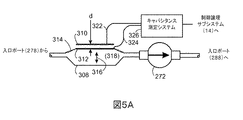
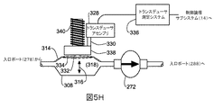
ある実施形態において、膜ポンプにより供給される量は「開ループ」方式で実行されてもよく、ポンプの各ストロークで予想量の流体が供給されたことを検出し、確認する機構を設けなくてもよい。他の実施形態において、膜の1ストローク中にポンプ室を通じて吐出される流体の量は、流体管理システム(Fluid Management System)(FMS)技術を使用して測定されてもよく、これは米国特許第4,808,161号明細書(代理人整理番号A38)、同第4,826,482号明細書(代理人整理番号A43)、同第4,976,162号明細書(代理人整理番号A52)、同第5,088,515号明細書(代理人整理番号A49)、同第5,350,357号明細書(代理人整理番号147)により詳しく説明されており、これらのすべての全文を参照によって本願に援用する。簡潔に言えば、FMS測定法は、膜型ポンプの各ストロークで供給される流体の量を検出するために使用される。小さい一定の基準空気室がポンプアセンブリの外側、たとえば空気圧マニホルド(図示せず)の中に配置される。弁によって基準室と第二の圧力センサが分離される。ポンプの1回吐出量は、基準室に空気を充満させて、圧力を測定し、その後、弁をポンプ室に向かって開放することによって正確に計算されうる。基準室側の空気の量は、基準室の一定量と、基準室がポンプ室に接続された時の圧力変化に基づいて計算されうる。いくつかの実施形態において、膜の1ストローク中にポンプ室を通じて吐出される流体の量は音響体積検出(Acoustic Volume Sensing)(AVS)法を使用して測定されてもよい。音響体積測定法は、DEKA Products Limited Partnershipに譲渡された米国特許第5,575,310号明細書(代理人整理番号B28)と同第5,755,683号明細書(代理人整理番号B13)および、米国特許出願公開第2007/0228071 A1号明細書(代理人整理番号E70)、同第2007/0219496 A1号明細書、第2007/0219480 A1号明細書、同第2007/0219597 A1号明細書、国際出願第2009/088956号パンフレットの主題であり、そのすべてを参照によって本願に援用する。この実施形態ではナノリットル範囲での流体量検出が可能であり、それゆえ、吐出量の非常に正確で精密な監視に役立つ。流体流量を測定するためのその他の代替的技術もまた使用でき、たとえば、ドップラに基づく方法、ホール効果センサとベーンまたはフラッパ弁との併用、ストレインビーム(たとえば、流体室の上の柔軟膜に関して、この柔軟膜のたわみを検出する)、プレートを用いた容量性検出の使用、または温度飛行時間法がある。 In some embodiments, the amount supplied by the membrane pump may be implemented in an “open loop” manner, without providing a mechanism to detect and confirm that an expected amount of fluid has been supplied with each stroke of the pump. Also good. In other embodiments, the amount of fluid dispensed through the pump chamber during one stroke of the membrane may be measured using Fluid Management System (FMS) technology, which is described in US Pat. No. 4,808,161 (Agency reference number A38), No. 4,826,482 (Agency reference number A43), No. 4,976,162 (Agency reference number A52) ), No. 5,088,515 (Agency reference number A49) and No. 5,350,357 (Agency reference number 147). Which is incorporated herein by reference. Briefly, the FMS measurement method is used to detect the amount of fluid delivered with each stroke of the membrane pump. A small constant reference air chamber is located outside the pump assembly, eg, in a pneumatic manifold (not shown). A valve separates the reference chamber and the second pressure sensor. The pump stroke can be accurately calculated by filling the reference chamber with air, measuring the pressure, and then opening the valve towards the pump chamber. The amount of air on the reference chamber side can be calculated based on a certain amount of the reference chamber and a change in pressure when the reference chamber is connected to the pump chamber. In some embodiments, the amount of fluid dispensed through the pump chamber during one stroke of the membrane may be measured using an Acoustic Volume Sensing (AVS) method. Acoustic volume measurement methods are disclosed in US Pat. Nos. 5,575,310 (Attorney Docket B28) and 5,755,683 (Attorney Docket B13) assigned to DEKA Products Limited Partnership. And US Patent Application Publication No. 2007/0228071 A1 (Attorney Docket No. E70), 2007/0219496 A1, 2007/0219480 A1, 2007/0219597 A1. , International Application No. 2009/088956, the entirety of which is incorporated herein by reference. This embodiment allows detection of fluid volume in the nanoliter range and is therefore useful for very accurate and precise monitoring of discharge volume. Other alternative techniques for measuring fluid flow can also be used, such as Doppler based methods, combined use of Hall effect sensors and vane or flapper valves, strain beams (e.g., for flexible membranes above fluid chambers, Detect the deflection of this flexible membrane), use capacitive sensing with plates, or temperature time-of-flight.
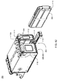
製品モジュールアセンブリ250は、ブラケットアセンブリ282と釈放可能に係合するように構成されてもよい。ブラケットアセンブリ282は、加工システム10の一部であって(、およびその中に剛性に固定されていて)もよい。本明細書では「ブラケットアセンブリ」と呼ぶが、このアセンブリは他の実施形態では異なっていてもよい。ブラケットアセンブリは、所望の場所に製品モジュールアセンブリ282を固定するのに役立つ。ブラケットアセンブリ282の一例には、製品モジュール250と釈放可能に係合するように構成された、加工システム10の中の棚が含まれていてもよいが、これに限定されない。たとえば、製品モジュール250は係合装置(たとえば、クリップアセンブリ、スロットアセンブリ、ラッチアセンブリ、ピンアセンブリ)を含んでいてもよく、これはブラケットアセンブリ282に組み込まれた相補的装置と釈放可能に係合するように構成される。
配管/制御サブシステム20はマニホルドアセンブリ284を含んでいもよく、これはブラケットアセンブリ282に剛性に固定されていてもよい。マニホルドアセンブリ284は、複数の入口ポート286、288、290、292を含むように構成されてもよく、これらは、ポンプアセンブリ270、272、274、276の各々に組み込まれたポンプ開口部(たとえば、ポンプ開口部294、296、298、300)と釈放可能に係合するように構成されていてもよい。製品モジュール250をブラケットアセンブリ282に位置付ける際、製品モジュール250を矢印302の方向に移動してもよく、それゆえ、入口ポート286、288、290、292が(それぞれ)ポンプ開口部294、296、298、300と釈放可能に係合できる。入口ポート286、288、290、292および/またはポンプ開口部294、296、298、300は、上述のような1つまたは複数のOリングまたはその他のシーリングアセンブリ(図示せず)を含み、漏出防止シール状態としやすくなってもよい。マニホルドアセンブリ284に含められる入口ポート(たとえば、入口ポート286、288、290、292)は剛性の「パイプ様」の材料で構成されてもよく、または柔軟な「チューブ様」の材料で構成されてももよい。
The plumbing /
マニホルドアセンブリ284はチューブ束304と係合するように構成されていてもよく、これはノズル24へと(直接または間接に)配管されてもよい。前述のように、大量原料サブシステム16はまた、少なくとも1つの実施形態において、冷却された炭酸水164、冷却された水166および/または冷却された高果糖コーンシロップ168の形態の流体を(直接または間接に)ノズル24に供給する。したがって、制御論理サブシステム14が(この特定の例において)、具体的な量の各種の大量原料、たとえば冷却された炭酸水164、冷却された水166、冷却された高果糖コーンシロップ168と、各種のマイクロ原料(たとえば、第一の基質(すなわち、フレーバリング、第二の基質(すなわち、栄養補助成分と、第三の基質(すなわち、医薬品)の量を調整できるため、制御論理サブシステム14は製品28の組成を正確に制御しうる。
上述のように、ポンプアセンブリ270、272、274、276の1つまたは複数はソレノイドピストンポンプアセンブリであってもよく、これはポンプアセンブリ270、272、274、276の1つまたは複数が論理サブシステム14によって(データバス38を介して)通電されるたびに、所定の、常に同じ量の流体を供給する。さらに、上述のように、制御論理サブシステム14は1つまたは複数の制御プロセス120を実行してもよく、これは加工システム10の動作を制御してもよい。このような制御プロセスの一例には、データバス38を介して制御論理サブシステム14からポンプアセンブリ270、272、274、276に供給されうる駆動信号を生成する駆動信号生成プロセス(図示せず)が含まれていてもよい。上述の駆動信号の生成のための1つの例示的な方法が、2007年9月6日に出願され、現在、米国特許7,905,373号明細書(代理人整理番号F45)となった、“SYSTEM AND METHOD FOR GENERATING A DRIVE SIGNAL”と題する米国特許出願第11/851,344号明細書において開示されており、その全文を参照によって本願に援用する。
As described above, one or more of the
図4は1つのノズル24を示しているが、他の各種の実施形態においては、複数のノズル24が含まれていてもよい。いくつかの実施形態において、複数の容器30が、たとえばチューブ束の複数の集合を介してシステムから注出される製品を受け取ってもよい。それゆえ、いくつかの実施形態において、注出システムは、1人または複数の使用者が1種または複数種の製品を同ときに注出することを要求できるように構成されてもよい。
Although FIG. 4 shows one
容量性流量センサ306、308、310、312は、ポンプアセンブリ270、272、274、276の各々を通る上述のマイクロ原料の流量を検出するために使用されてもよい。
図5A(側面図)と図5B(上面図)も参照すると、例示的な容量性流量センサ308の詳細図が示されている。容量性流量センサ308は、第一の容量性プレート310と第二の容量性プレート312を含んでいてもよい。第二の容量性プレート312は、第一の容量性プレート310に関して移動可能に構成されていてもよい。たとえば、第一の容量性プレート310は、加工システム10の中の構造に剛性に固定されていてもよい。さらに、容量性流量センサ308もまた、加工システム10の中の構造に剛性に固定されてもよい。しかしながら、第二の容量性プレート312は、ダイアフラムアセンブリ314を使用することにより、第一の容量性プレート310(と容量性流量センサ308)に関して移動可能に構成されてもよい。ダイアフラムアセンブリ314は、第二の容量性プレート312が矢印316の方向に変位できるように構成されていてもよい。ダイアフラムアセンブリ314は、矢印316への変位を可能にする各種の材料で構成されてもよい。たとえば、ダイアフラムアセンブリ314は、ステンレススチール薄片にステンレススチール薄片の腐食を防止するためのPET(すなわち、ポリエチレンテレフタレート)コーティングを施したもので構成されてもよい。あるいは、ダイアフラムアセンブリ314はチタン薄片で構成されてもよい。またさらに、ダイアフラムアセンブリ314はプラスチックで構成されてもよく、この場合、プラスチックのダイアフラムアセンブリの一方の面をめっきして、第二の容量性プレート312を形成する。いくつかの実施形態において、プラスチックは、射出成形プラスチックまたはPET圧延シートであってもよいが、これらに限定されない。
Referring also to FIG. 5A (side view) and FIG. 5B (top view), a detailed view of an exemplary
上述のように、ポンプアセンブリ(たとえば、ポンプアセンブリ272)がデータバス38を介して制御論理サブシステム14により通電されるたびに、ポンプアセンブリは、たとえば製品容器254の中に収容されている適当なマイクロ原料の流体を校正に基づく量、たとえば30〜33μLだけ供給してもよい。したがって、制御論理サブシステム14は、適当なポンプアセンブリを通電させる速度を制御することによってマイクロ原料の流速を制御してもよい。ポンプアセンブリを通電させる例示的な速度は3Hz(すなわち、1秒間に3回)〜30Hz(すなわち、1秒間に30回)の間である。
As described above, each time a pump assembly (e.g., pump assembly 272) is energized by
したがって、ポンプアセンブリ272が通電すると、(容量性流量センサ308の空洞318の中に)吸引力が発生し、これは、たとえば製品容器254から適当なマイクロ原料(たとえば、基質)を吸引する。したがって、ポンプアセンブリ272が通電し、空洞318内に吸引力が発生すると、第二の容量性プレート312が下方に変位してもよく(図5Aに関する)、それゆえ、距離「d」(すなわち、第一の容量性プレート310と第二の容量性プレート312との間の距離)が増大する。
Thus, when the
図5Cも参照すると、当業界で知られていように、コンデンサのキャパシタンス(C)は、下式、
![]()
![]()
引き続き上記の例に関し、図5Dも参照して、ポンプアセンブリ272が通電していない時、第一の容量性プレート310と第二の容量性プレート312により形成されるコンデンサの数値は5.00pFであると仮定する。さらに、ポンプアセンブリ272が時間T=1で通電すると、空洞316の中に吸引力が発生し、これは、第二の容量性プレート312を下方に、第一の容量性プレート310と第二の容量性プレート312によって形成されるコンデンサのキャパシタンスを20%減少できる距離だけ変位するのに十分であると仮定する。したがって、第一の容量性プレート310と第二の容量性プレート312により形成されるコンデンサの新たな数値は4.00pFであってもよい。上述のポンピングシーケンス中に第二の容量性プレート312が下方に変位する例示的な例が図5Eに示されている。
Continuing with the above example, also referring to FIG. 5D, when the
適当なマイクロ原料が製品容器254から吸引されると、空洞318内の吸引力が低下し、第二の容量性プレート312が上方に、その当初の位置(図5Aに示される)へと変位してもよい。第二の容量性プレート312が上方に変位するにつれて、第二の容量性プレート312と第一の容量性プレート310との間の距離が短くなり、その当初の値に戻ってもよい。したがって、第一の容量性プレート310と第二の容量性プレート312により形成されるコンデンサのキャパシタンスは再び5.00pFとなってもよい。第二の容量性プレート312が上方に移動し、その当初の位置に戻りつつある時、第二の容量性プレート312の運動量によって、第二の容量性プレート312はその当初の位置を通り過ぎ、一瞬、第二の容量性プレート312が当初の位置にある時(図5Aに示される)よりも第一の容量性プレートに近付く。したがって、第一の容量性プレート310と第二の容量性プレート312により形成されるコンデンサのキャパシタンスは一瞬、その当初の値5.00pFより大きくなりその後まもなく5.00pFで安定しうる。
As the appropriate micro-raw material is aspirated from the
ポンプアセンブリ272がオンとオフのサイクルを繰り返す間の上述のようなキャパシタンスの値の(この例では)5.00pFと4.00pFとの間での変化は、たとえば製品容器254が空になるまで継続しうる。例示のために、製品容器254は時間T=5で空になると仮定する。この時点で、第二の容量性プレート312は、その当初の位置(図5Aに示される)に戻らないかもしれない。さらに、ポンプアセンブリ272がサイクルを続けると、第二の容量性プレート312は、最終的に第二の容量性プレート312がそれ以上変位できなくなる(図5Fに示される)まで引き続き下方に吸引されうる。この時点で、距離「d」が図5Aと図5Eに示されるものより大きくなるため、第一の容量性プレート310と第二の容量性プレート312により形成されるコンデンサのキャパシタンスの値は最小のキャパシタンスの数値320に極小化されうる。最小キャパシタンス値320の実際の数値は、ダイアフラムアセンブリ314の柔軟性に応じて異なっていてもよい。
The change in capacitance value as described above (in this example) between 5.00 pF and 4.00 pF while the
したがって、第一の容量性プレート310と第二の容量性プレート312によって形成されるコンデンサのキャパシタンスの値(絶対変動または頂点間変動)を監視することによって、たとえばポンプアセンブリ272の適正な動作を検証できる。たとえば、上述のキャパシタンスの値が5.00pFと4.00pFの間で周期的に変動すれば、このキャパシタンスの変動は、ポンプアセンブリ272が適正に動作していて、製品容器254が空ではないことを示しうる。しかしながら、上述のキャパシタンスの値が変動しない(たとえば、5.00pFのままである)場合、これはポンプアセンブリ272の故障(たとえば、ポンプアセンブリの中の機械的構成部品が故障した、および/または電気的構成部品が故障したこと)またはノズル24が目詰まりを起こしたことを示しうる。
Thus, for example, proper operation of the
さらに、上述のキャパシタンスの値が4.00pFより低い点まで(最小キャパシタンス値320まで等)低下した場合、これは製品容器254が空であることを示しうる。またさらに、頂点間変動が予想以下(たとえば、上述の1.00pFの変動量未満)であった場合、これは製品容器254と容量性流量センサ308の間に漏出があることを示しうる。
Furthermore, if the capacitance value described above drops to a point below 4.00 pF (such as to a minimum capacitance value of 320), this may indicate that the
第一の容量性プレート310と第二の容量性プレート312によって形成されるコンデンサのキャパシタンスの値を測定するために、(導体322、324を介して)信号がキャパシタンス測定システム326に供給されてもよい。キャパシタンス測定システム326の出力は、制御論理サブシステム14に供給されてもよい。キャパシタンス測定システム326の例には、California、San JoseのCypress Semiconductorが提供するCY8C21434−24LFXI PSOCが含まれていてもよく、その設計と動作はCypress Semicoductorが発行した“CSD User Module”に記載されており、これを参照によって本願に援用する。キャパシタンス測定回路326は環境要素(たとえば、温度、湿度、電源供給電圧の変化)を補償するように構成されてもよい。
In order to measure the capacitance value of the capacitor formed by the
キャパシタンス測定システム326は、所定の時間にわたって(第一の容量性プレート310と第二の容量性プレート312で形成されるコンデンサに関する)キャパシタンス測定を行って、キャパシタンスの上述の変動が発生しているか否かを判定するように構成されてもよい。たとえば、キャパシタンス測定システム326は、0.50秒の時間枠で発生する上述のキャパシタンス値の変化を監視するように構成されてもよい。したがって、この特定の例において、ポンプアセンブリ272に最低速度2.00Hzで(すなわち、0.50秒ごとに少なくとも1回)通電されるかぎり、各0.50秒の測定サイクル中にキャパシタンス測定システム326が上記のキャパシタンス変動の少なくとも1つを検出するはずである。
流量センサ308は容量性として上述されているが、これは例示のためにすぎず、他の構成も可能であり、本願の範囲内であると考えられるため、本願の限定となることは意図されない。
Although the
たとえば、図5Gも参照して、例示のために、流量センサ308が第一の容量性プレート310と第二の容量性プレート312を含まないと仮定する。その代わりに、流量センサ308はトランスデューサアセンブリ328を含んでいてもよく、これは(直接または間接に)ダイアフラムアセンブリ314に連結されてもよい。直接連結される場合、トランスデューサアセンブリ328はダイアフラムアセンブリ314に取り付けられ/付着されてもよい。あるいは、間接に連結される場合、トランスデューサアセンブリ328は、たとえば連結アセンブリ330でダイアフラムアセンブリ314に連結されてもよい。
For example, referring also to FIG. 5G, for purposes of illustration, assume that the
上述のように、流体が空洞318の中で変位すると、ダイアフラムアセンブリ314が変位しうる。たとえば、ダイアフラムアセンブリ314は矢印316の方向に移動してもよい。これに加えて/その代わりに、ダイアフラムアセンブリ314は歪んでもよい(たとえば、破線のダイアフラムアセンブリ332、334で示されるように、わずかに凹状/凸状となる)。当業界で知られているように、(a)ダイアフラムアセンブリ314が、矢印316の方向への変位中に基本的に平坦のままであるか、(b)矢印316に関して静止状態のままである間に、撓んで凸状のダイアフラムアセンブリ332/凹状のダイアフラムアセンブリ334となるか、または(c)両方の変位形態の組み合わせを示すか、は、複数の要素(たとえば、ダイアフラムアセンブリ314の様々な部分の剛性等)に依存しうる。したがって、トランスデューサアセンブリ328を(連結アセンブリ330および/またはトランスデューサ測定システム336と組み合わせて)利用して、ダイアフラムアセンブリ314の全部または一部の変位を監視することにより、空洞318の中で変位する流体の量を測定できる。
As described above,
様々な種類のトランスデューサアセンブリ(以下により詳しく説明する)の使用により、空洞318を通過する流体の量を測定できる。
By using various types of transducer assemblies (described in more detail below), the amount of fluid passing through the
たとえば、トランスデューサアセンブリ328は線形可変作動変圧器(LVDT)を含んでいてもよく、加工システム10の中の構造に剛性に固定されてもよく、これらは連結アセンブリ330を介してダイアフラムアセンブリ314に連結されてもよい。このようなLVDTの例示的で非限定的な例は、New Jersey、PennsaukenのMacro Sensorsが製造するSE 750 100である。流量センサ308もまた、加工システム10の中の構造に剛性に固定されてもよい。したがって、ダイアフラムアセンブリ314が(たとえば、矢印316に沿って、または凸状/凹状となるように撓むように)変位すると、ダイアフラムアセンブリ314の運動が監視されうる。したがって、空洞318を通過する流体の量も監視されうる。トランスデューサアセンブリ328(すなわち、これはLVDTを含む)は信号を生成してもよく、これはトランスブューサ測定システム336によって処理(たとえば、増幅/変換/フィルタ処理)されてもよい。処理されたこの信号は次に、制御論理サブシステム14に供給されて、空洞318を通過する流体の量を確認するために使用されてもよい。
For example, the
あるいは、トランスデューサアセンブリ328は針/磁気カートリッジアセンブリ(たとえば、蓄音機用針/磁気カートリッジアセンブリ)を含んでいてもよく、加工システム10の中の構造に剛性に固定されていてもよい。このような針/磁気カートリッジアセンブリの例示的で非限定的な例は、日本の株式会社東芝が製造するN 16 Dである。トランスブューサアセンブリ328は、連結アセンブリ330(たとえば、剛性ロッドアセンブリ)を介してダイアフラムアセンブリ314に連結されてもよい。トランスデューサアセンブリ328の針は、連結アセンブリ330(すなわち、剛性ロッドアセンブリ)の表面と接触するように構成されてもよい。したがって、ダイアフラムアセンブリ314が(上述のように)変位し/撓むと、連結アセンブリ330(すなわち、剛性ロッドアセンブリ)もまた(矢印316の方向に)変位し、トランスデューサアセンブリ328の針に当たって擦れるかもしれない。したがって、トランスデューサアセンブリ328(すなわち、針/磁気カートリッジ)と連結アセンブリ330(すなわち、剛性ロッドアセンブリ)の組み合わせが信号を生成してもよく、これはトランスデューサ測定システム336によって処理(たとえば、増幅/変換/フィルタ処理)されてもよい。処理されたこの信号は次に、制御論理サブシステム14に供給されて、空洞318を通過する流体の量を確認するために使用されてもよい。
Alternatively, the
あるいは、トランスデューサアセンブリ328は磁気コイルアセンブリ(たとえば、スピーカアセンブリのボイスコイルと同様)を含んでいてもよく、加工システム10の中の構造に剛性に固定されていてもよい。このような磁気コイルアセンブリの例示的で非限定的な例は、New York、East AuroraのAPI Delevan Inc.が製造する5526−Iである。トランスデューサアセンブリ328は、連結アセンブリ330を介してダイアフラムアセンブリ314に連結されてもよく、これは軸磁石アセンブリを含んでいてもよい。このような軸磁石アセンブリの例示的で非限定的な例は、Pennsylvania、JamisonのK&J Magnetics,Inc.が製造するD16である。連結アセンブリ330に含められる軸磁石アセンブリは、トランスデューサアセンブリ328の磁気コイルアセンブリの中で同軸的にスライドするように構成されていてもよい。したがって、ダイアフラムアセンブリ314が(上述のように)変位し/撓むと、連結アセンブリ330(すなわち、軸磁石アセンブリ)もまた(矢印316の方向に)変位する。当業界で知られているように、磁気コイルアセンブリ内の軸磁石アセンブリの運動は、磁気コイルアセンブリの巻線内に電流を誘起する。したがって、トランスデューサアセンブリ328の磁気コイルアセンブリ(図示せず)と連結アセンブリ330の軸磁石アセンブリ(図示せず)の組み合わせが信号を生成してもよく、これは処理(たとえば、増幅/変換/フィルタ処理)され、その後、制御論理サブシステム14に供給され、空洞318を通過する流体の量を確認するために使用されてもよい。
Alternatively, the
あるいは、トランスデューサアセンブリ328はホール効果センサアセンブリを含んでいてもよく、加工システム10の中の構造に剛性に固定されていてもよい。このようなホール効果センサアセンブリの例示的で非限定的な例は、Massachusetts、WorcesterのAllegro Microsystems Inc.が製造するAB0iKUA−Tである。トランスデューサアセンブリ328は、連結アセンブリ330を介してダイアフラムアセンブリ314に連結されてもよく、これは軸磁石アセンブリを含んでいてもよい。このような軸磁石アセンブリの例示的で非限定的な例は、Pennsylvania、JamisonのK&J Magnetics,Inc.が製造するD16である。連結アセンブリ330に含められる軸磁石アセンブリは、トランスデューサアセンブリ328のホール効果センサアセンブリの付近に位置付けられるように構成されてもよい。したがって、ダイアフラムアセンブリ314が(上述のように)変位し/撓むと、連結アセンブリ330(すなわち、軸磁石アセンブリ)もまた(矢印316の方向に)変位する。当業界で知られているように、ホール効果センサアセンブリは、磁場の変化に応答して変化する出力電圧信号を生成するアセンブリである。したがって、トランスデューサアセンブリ328のホール効果センサアセンブリ(図示せず)と連結アセンブリ330の軸磁石アセンブリ(図示せず)の組み合わせが信号を生成してもよく、これは処理(たとえば、増幅/変換/フィルタ処理)され、その後、制御論理サブシステム14に供給され、空洞318を通過する流体の量を確認するために使用されてもよい。
Alternatively, the
本明細書において、圧電物質とは、圧電効果を示すあらゆる物質を指す。この物質には、セラミック、フィルム、金属、水晶が含まれていてもよいが、これらに限定されない。 In this specification, the piezoelectric substance refers to any substance that exhibits a piezoelectric effect. This material may include but is not limited to ceramic, film, metal, quartz.
あるいは、トランスデューサアセンブリ328は圧電ブザー素子を含んでいてもよく、これはダイアフラムアセンブリ314に直接連結されてもよい。したがって、連結アセンブリ330を使用しなくてよい。このような圧電ブザー素子の例示的で非限定的な例は、South Carolina、Myrtle BeachのAVX Corporationが製造するKBS−13DA−12Aである。当業界で知られているように、圧電ブザー素子は電気出力信号を生成してもよく、これは圧電ブザー素子が受ける機械的応力の量に応じて変化する。したがって、ダイアフラムアセンブリ314が(上述のように)変位し/撓むと、(トランスデューサアセンブリ328に含まれる)圧電ブザー素子が機械的応力を受ける可能性があり、したがって、信号が生成されてもよく、これがトランスデューサ測定システム336によって処理(たとえば、増幅/変換/フィルタ処理)されてもよい。その後、処理されたこの信号が制御論理サブシステム14に供給されて、空洞318を通過する流体の量を確認するために使用されてもよい。
Alternatively, the
あるいは、トランスデューサアセンブリ328は圧電シート素子を含んでいてもよく、これはダイアフラムアセンブリ314に直接連結されてもよい。したがって、連結アセンブリ330を利用しなくてよい。このような圧電シート素子の例示的で非限定的な例は、Virginia、HamptonのMSI/Schaevitzが製造する0−1002794−0である。当業界で知られているように、圧電シート素子は電気出力信号を生成してもよく、これは圧電シート素子が受ける機械的応力の量に応じて変化する。したがって、ダイアフラムアセンブリ314が(上述のように)変位し/撓むと、(トランスデューサアセンブリ328に含まれる)圧電シート素子が機械的応力を受ける可能性があり、したがって、信号が生成されてもよく、これがトランスデューサ測定システム336によって処理(たとえば、増幅/変換/フィルタ処理)されてもよい。その後、処理されたこの信号が制御論理サブシステム14に供給されて、空洞318を通過する流体の量を確認するために使用されてもよい。
Alternatively, the
あるいは、(トランスデューサアセンブリ328に含まれる)上述の圧電シート素子は、ダイアフラムアセンブリ314の付近に位置付けられ、音響的にこれに連結されてもよい。(トランスデューサアセンブリ328に含まれる)圧電シート素子は、圧電シート素子の共鳴能力を向上させるための重み付けアセンブリを含んでいても、含んでいなくてもよい。したがって、ダイアフラムアセンブリ314が(上述のように)変位し/撓むと、(トランスデューサアセンブリ328に含まれる)圧電シート素子は(音響連結によって)機械的応力を受ける可能性があり、したがって、信号が生成されてもよく、これがトランスデューサ測定システム336によって処理(たとえば、増幅/変換/フィルタ処理)されてもよい。その後、処理されたこの信号は制御論理サブシステム14に供給されて、空洞318を通過する流体の量を確認するために使用されてもよい。
Alternatively, the piezoelectric sheet element described above (included in transducer assembly 328) may be positioned near
あるいは、トランスデューサアセンブリ328はオーディオスピーカアセンブリを含んでいてもよく、この場合、オーディオスピーカアセンブリのコーンが直接ダイアフラムアセンブリ314に連結されてもよい。したがって、連結アセンブリ330を利用しなくてよい。このようなオーディオスピーカアセンブリの例示的で非限定的な例は、Ohio、DaytonのProjects Unlimitedが製造するAS01308MR−2Xである。当業界で知られているように、オーディオスピーカアセンブリはボイスコイルアセンブリと、ボイスコイルアセンブリがその中でスライドする永久磁石アセンブリを含んでいてもよい。信号は一般にボイスコイルアセンブリに印加されて、スピーカコーンを移動させるが、スピーカを手で移動させると、電流がボイスコイルアセンブリの中に誘起される。したがって、ダイアフラムアセンブリ314が(前述のように)変位し/撓むと、(トランスデューサアセンブリ328に含まれる)オーディオスピーカアセンブリのボイスコイルは、上述の永久磁石アセンブリに関して変位する可能性があり、したがって、信号が生成されてもよく、これがトランスデューサ測定システム336によって処理(たとえば、増幅/変換/フィルタ処理)されてもよい。その後、処理されたこの信号は制御論理サブシステム14に供給されて、空洞318を通過する流体の量を確認するために使用されてもよい。
Alternatively, the
あるいは、トランスデューサアセンブリ328は加速度計アセンブリを含んでいてもよく、これはダイアフラムアセンブリ314に直接連結されてもよい。したがって、連結アセンブリ330を利用しなくてもよい。このような加速度計アセンブリの例示的で非限定的な例は、Massachusetts、NorwoodのAnalog Devices,Inc.が製造するAD22286−R2である。当業界で知られているように、加速度計アセンブリは電気出力信号を生成でき、これは、加速度計アセンブリが受ける加速度に応じて変化する。したがって、ダイアフラムアセンブリ314が(上述のように)変位し/撓むと、(トランスデューサアセンブリ328に含まれる)加速度計アセンブリが異なるレベルの加速度を受ける可能性があり、したがって、信号が生成されてもよく、これはトランスデューサ測定システム336によって処理(たとえば、増幅/変換/フィルタ処理)されてもよい。その後、処理されたこの信号は制御論理サブシステム14に供給されて、チャンバ318を通過する流体の量を確認するために使用されてもよい。
Alternatively,
あるいは、トランスデューサアセンブリ328はマイクロフォンアセンブリを含んでいてもよく、これはダイアフラムアセンブリ314の付近に位置付けられ、音響的にこれに連結されてもよい。したがって、連結アセンブリ330を利用しなくてよい。このようなマイクロフォンアセンブリの例示的で非限定的な例は、Illinois、ItascaのKnowles Acousticsが製造するEA−21842である。したがって、ダイアフラムアセンブリ314が(上述のように)変位し/撓むと、(トランスデューサアセンブリ328に含まれる)マイクロフォンアセンブリが(音響連結によって)機械的応力を受ける可能性があり、したがって、信号が生成されてもよく、これはトランスデューサ測定システム336によって処理(たとえば、増幅/変換/フィルタ処理)されてもよい。その後、処理されたこの信号は制御論理サブシステム14に供給されて、空洞318を通過する流体の量を確認するために使用されてもよい。
Alternatively, the
あるいは、トランスデューサアセンブリ328は、ダイアフラムアセンブリ314の運動を監視するように構成された光学変位アセンブリを含んでいてもよい。したがって、連結アセンブリ330を利用しなくてよい。このような光学変位アセンブリの例示的で非限定的な例は、New York、PittsfordのAdvanced Motion Systems,Inc.が製造するZ4W−Vである。例示のために、上述の光学変位アセンブリは光信号発生器を含み、これは光信号をダイアフラムアセンブリ314へと方向付け、これがダイアフラムアセンブリ314により反射され、(同様に光学変位アセンブリの中に含まれる)光センサによって検出される。したがって、ダイアフラムアセンブリ314が(上述のように)変位し/撓むと、(トランスデューサアセンブリ328に含まれる)上述の光センサによって検出された光信号が変化する可能性がある。したがって(トランスデューサアセンブリ328に含まれる)光学変位アセンブリによって信号が生成されてもよく、これはトランスデューサ測定システム336によって処理(たとえば、増幅/変換/フィルタ処理)されてもよい。その後、処理されたこの信号は制御論理サブシステム14に供給されて、空洞318を通過する流体の量を確認するために使用されてもよい。
Alternatively, the
流量センサ308の上記の例は例示のためのものであるが、他の構成も可能であり、本願の範囲内に含まれると考えられるため、これらがすべてとされることは意図されない。たとえば、トランスデューサアセンブリ328は、ダイアフラムアセンブリ314の外部に位置付けられるように示されているが、トランスデューサアセンブリ328は空洞318の中に位置付けられてもよい。
The above example of the
流量センサ308の上述の例のいくつかは、ダイアフラムアセンブリ314に連結されているように説明されているが、これは例示のためにすぎず、他の構成も可能であり、本願の範囲に含まれると考えられるため、本願の限定となることは意図されない。たとえば、図5Hも参照すると、流量センサ308はピストンアセンブリ338を含んでいてもよく、これは、ばねアセンブリ340により付勢されていてもよい。ピストンアセンブリ338は、ダイアフラムアセンブリ314の付近に位置付けられて、これを付勢するように構成されていてもよい。したがって、ピストンアセンブリ338はダイアフラムアセンブリ314の運動に追従できる。したがって、トランスデューサアセンブリ328は、ピストンアセンブリ338に連結されて、上述の結果を達成してもよい。
Although some of the above examples of
さらに、流量センサ308がピストンアセンブリ338とばねアセンブリ340を含むように構成されている場合、トランスデューサアセンブリ328は、ばねアセンブリ340のインダクタンスを監視するように構成されたインダクタンス監視アセンブリを含んでいてもよい。したがって、連結アセンブリ330を利用しなくてよい。このようなインダクタンス監視アセンブリの例示的で非限定的な例は、Washington、AuburnのAlmost All Digital Electronicsが製造するL/C Meter IIBである。したがって、ダイアフラムアセンブリ314が(上述のように)変位し/撓むと、(トランスデューサアセンブリ328に含まれる)上記のインダクタンス監視アセンブリが検出するばねアセンブリ340のインダクタンスは、ばねアセンブリ340が撓む際の抵抗の変化によって変化する可能性がある。したがって、(トランスデューサアセンブリ328に含まれる)インダクタンス監視アセンブリによって信号が生成されてもよく、これはトランスデューサ測定システム336によって処理(たとえば、増幅/変換/フィルタ処理)されてもよい。その後、処理されたこの信号は制御論理サブシステム14に供給されて、チャンバ318を通過する流体の量を確認するために使用されてもよい。
Further, if the
図6Aも参照すると、配管/制御サブシステム20の概略図が示されている。後述の配管/制御サブシステムは流量制御モジュール170を介して製品28に加えられる冷却された炭酸水164の量を制御するために使用される配管/制御システムに関しているが、これは例示のためにすぎず、他の構成もまた可能であるため、本願の限定となることは意図されない。たとえば、後述の配管/制御サブシステムはまた、たとえば、製品28に加えられる(たとえば、流量制御もシュール172を介した)冷却された水166および/または(たとえば、流量制御モジュール174を介した)冷却された高果糖コーンシロップ168の量を制御するためにも使用されてよい。
Referring also to FIG. 6A, a schematic diagram of the piping /
上述のように、配管/制御サブシステム20はフィードバックコントローラシステム188を含んでいてもよく、これは流量測定装置176からの流量フィードバック信号182を受け取る。フィードバックコントローラシステム188は、流量フィードバック信号182を所望の流量(データバス38を介して制御論理サブシステム14により設定される)と比較してもよい。流量フィードバック信号182を処理すると、フィードバック制御システム188は流量制御信号194を生成してもよく、これが可変ラインインピーダンス200に供給されてもよい。
As described above, the plumbing /
フィードバックコントローラシステム188は、軌道整形コントローラ350と、流量調整器352と、フィードフォワードコントローラ354と、ユニット遅延356と、飽和コントローラ358と、ステッパコントローラ360と、を含んでいてもよく、その各々について、以下に詳しく説明する。
The
軌道整形コントローラ350は、データバス38を介して制御論理サブシステム14から制御信号を受けるように構成されていてもよい。この制御信号は、配管/制御サブシステム20が製品28に使用するための流体(この場合、流量制御モジュール170を介した冷却された炭酸水164)を送達すると想定される方法のための軌道を設定してもよい。しかしながら、制御論理サブシステム14により提供される軌道は、たとえば流量コントローラ352によって処理される前に調整する必要があるかもしれない。たとえば制御システムは、複数のライン区間で構成される制御曲線(すなわち、ステップの変化を含む)を処理しにくい傾向がある。たとえば、流量調整器352は制御曲線370を処理しにくいかもしれず、それは、これが3つの異なる直線区間、すなわち区間372、374、376で構成されるからである。したがって、遷移点(遷移点378、380等)において、具体的には流量コントローラ352(および、全体としては配管/制御サブシステム20)は、第一の流速から第二の流速に瞬ときに変化させる必要があるであろう。したがって、軌道整形コントローラ350は、制御曲線30をフィルタ処理して、平滑な制御曲線382を形成してもよく、これは第一の流速から第二の流速への瞬時の変化が不要となるため、具体的には流量コントローラ352(および、全体てしては配管/制御サブシステム20)によってより容易に処理されうる。
これに加えて、軌道整形コントローラ350によって、ノズル24の注入前の湿潤化と注入後のすすぎが可能となりうる。いくつかの実施形態において、および/またはいくつかのレシピについて、1種または複数種の原料は、原料(ここでは、「汚染原料」と呼ぶ)がノズル24に直接、すなわちそれが貯蔵されていた形態で接触すると、ノズル24にとって問題となる可能性がある。いくつかの実施形態において、ノズル24には、「注入前」の原料、たとえば水で注入前の湿潤化が行われてもよく、それによってこれらの「汚染原料」がノズル24と直接接触するのが防止される。ノズル24にはその後、「洗浄後原料」、たとえば水で注入後のすすぎが行われてもよい。
In addition, the
具体的には、ノズル24に、たとえば10mLの水で注入前の湿潤化が行われ、および/またはたとえば10mLの水または「洗浄後」の原料で注入後のすすぎが行われる場合、汚染原料の追加が停止すると、軌道整形コントローラ350は、注入プロセス中に追加の量の汚染原料を供給することによって、注入前の湿潤化および/または注入後のすすぎ中に加えられた洗浄前の原料が相殺されるようにしてもよい。具体的には、容器30に製品28が注入されている時、注入前のすすぎの水または「洗浄前」によって、当初は汚染成分の濃度不足の製品28が得られてもよい。すると、軌道整形コントローラ350は、汚染原料を必要な程度より高い流速で追加してもよく、その結果、製品28は「濃度不足」から「適正濃度」乃至「過剰濃度」に遷移するか、特定のレシピによって求められるレベルより高濃度で存在する。しかしながら、適正な量の汚染原料が添加されると、注入後のすすぎのプロセスで、追加の水、または他の適当な「洗浄後の原料」が加えられてもよく、その結果、再び汚染原料が「適正な濃度」である原料28が得られる。
Specifically, if the
流量コントローラ352は、比例積分(PI)ループコントローラとして構成されてもよい。流量コントローラ352は比較と処理を行ってもよく、これは概して、フィードバックコントローラシステム188により実行されると上述した。たとえば、流量コントローラ352は、流量測定器176からフィードバック信号182を受け取るように構成されていてもよい。流量コントローラ352は、流量フィードバック信号182を(制御論理サブシステム14によって設定され、軌道整形コントローラ350により調整される)所望の流量と比較してもよい。流量コントローラ352は、流量フィードバック信号182を処理すると、流量制御信号194を生成してもよく、これが可変ラインインピーダンス200に供給されてもよい。
The
フィードフォワードコントローラ354は、可変ラインインピーダンス200の初期位置がどこであるべきかに関する「最良推測」の予想値を提供してもよい。具体的には、所定の一定の圧力で、可変ラインインピーダンスの(冷却された炭酸水164の)流速は、0.00mL/秒〜120.00mL/秒の間であると仮定する。さらに、容器30に飲料製品28を注入するときに、40mL/秒の流速が望ましいと仮定する。したがって、フィードフォワードコントローラ354は、(フィードフォワードライン384で)フィードフォワード信号を供給してもよく、これは当初、可変ラインインピーダンス200をその最大開口度の33.33%まで開く(可変ラインインピーダンス200が線形に動作すると仮定する)。
The
フィードフォワード信号の値を決定する際、フィードフォワードコントローラ354はルックアップテーブル(図示せず)を利用してもよく、これは経験的に作成されてもよく、各種の初期流速について供給される信号を定義してもよい。このようなルックアップテーブルの一例には以下の表が含まれてもよいが、これに限定されない。
In determining the value of the feedforward signal, the

再び、たとえば容器30に飲料製品28を注入する際に40mL/秒の流速が望ましいと仮定すると、フィードフォワードコントローラ354は上記のルックアップテーブルを利用してもよく、(フィードフォワードライン384を使用して)ステッピングモータに60.0度回転させるパルス信号を送ってもよい。この例示的な実施形態においてはステッピングモータが使用されているが、他の各種の実施形態では、他のどのような種類のモータを使用してもよく、これにはサーボモータが含まれるが、これに限定されない。
Again, assuming, for example, that a flow rate of 40 mL / second is desired when injecting
ユニット遅延356はフィードバック経路を形成してもよく、これを通じて、(可変ラインインピーダンス200に供給される)制御信号の前のバージョンが流量コントローラ352に供給される。
飽和コントローラ358は、可変ラインインピーダンス200が(ステッパコントローラ360によって)最大流速に設定されたときには必ず、(上述のようにPIループコントローラとして構成されてもよい)フィードバックコントローラシステム188の積分制御を無効にするように構成されていてもよく、それゆえ、流速の超過とシステムの振動を低減させることにより、システムの安定性を向上させる。
The
ステッパコントローラ360は、(ライン386上で)飽和コントローラ358によって供給される信号を、可変ラインインピーダンス200が利用可能な信号に変換するように構成されていてもよい。可変ラインインピーダンス200は、可変ラインインピーダンス200の開口部の大きさ(およびしたがって、流速)を調整するためのステッピングモータを含んでいてもよい。したがって、制御信号194は、可変ラインインピーダンスに含まれるステッピングモータを制御するように構成されていてもよい。
The
図6Bも参照すると、それぞれ流速制御モジュール170、172、174の流量測定装置176、178、180の例には、パドルホイール流量測定装置、タービン型測定装置、または容積移送式流量測定装置(たとえば、歯車式容積移送式流量測定装置388)が含まれていてもよいが、これらに限定されない。それゆえ、各種の実施形態において、流量測定装置は、直接または間接に流量を測定できるどのような装置であってもよい。この例示的実施形態において、歯車式容積移送式流量測定装置388が使用されている。この実施形態において、流量測定装置388は複数の噛み合い歯車(たとえば、歯車390、392)を含んでいてもよく、これらはたとえば、歯車式容積移送式流量測定装置388を通過するあらゆる内容物が必ず1つまたは複数の所定の経路(たとえば、経路394、396)をたどるようにしてもよく、その結果、たとえば歯車390が反時計回りに回転し、歯車392が時計回りに回転する。歯車390、392の回転を監視することによって、フィードバック信号(たとえば、フィードバック信号182)が生成されて、適当な流量コントローラ(たとえば、流量コントローラ352)に供給されてもよい。
Referring also to FIG. 6B, examples of
図7〜14も参照すると、流量制御モジュール(たとえば、流量制御モジュール170)の各種の例示的実施形態が示されている。しかしながら、上述のように、各種のアセンブリの順序は様々な実施形態において異なっていてもよく、すなわち、アセンブリは、所望のどのような順序で配置されてもよい。たとえば、いつかの実施形態において、アセンブリは以下の順序、すなわち、流量測定装置、バイナリバルブ、可変インピーダンスの順で配置され、また他の実施形態では、アセンブリは以下の順序、すなわち流量測定装置、可変インピーダンス、バイナリバルブの順で配置される。いくつかの実施形態において、可変インピーダンス上の圧力と流体を保持するか、可変インピーダンス上の圧力を変化させるために、アセンブリの順序を変えることが望ましいかもしれない。いくつかの実施形態において、可変インピーダンスバルブはリップシールを含んでいてもよい。これらの実施形態では、リップシール上の圧力と流体を保持することが望ましいかもしれない。これは、アセンブリを以下の順序、すなわち、流量測定装置、可変インピーダンス、バイナリバルブの順とすることによって実現できる。可変ラインインピーダンスの下流にあるバイナリバルブは、リップシールが所望の密閉性を保持するように、可変インピーダンス上の圧力と液体を保持する。 Referring also to FIGS. 7-14, various exemplary embodiments of a flow control module (eg, flow control module 170) are shown. However, as described above, the order of the various assemblies may vary in various embodiments, i.e., the assemblies may be arranged in any desired order. For example, in some embodiments, the assembly is arranged in the following order: flow measurement device, binary valve, variable impedance, and in other embodiments, the assembly is in the following order: flow measurement device, variable Arranged in the order of impedance and binary valve. In some embodiments, it may be desirable to change the order of the assembly to retain pressure and fluid on the variable impedance or to change the pressure on the variable impedance. In some embodiments, the variable impedance valve may include a lip seal. In these embodiments, it may be desirable to maintain pressure and fluid on the lip seal. This can be achieved by placing the assembly in the following order: flow measurement device, variable impedance, binary valve. A binary valve downstream of the variable line impedance holds the pressure and liquid on the variable impedance so that the lip seal maintains the desired tightness.
まず図7Aと7Bを参照すると、流量制御モジュール170aの1つの実施形態が示されている。いくつかの実施形態において、流量制御モジュール170aは一般に、流量計176aと、可変ラインインピーダンス200aと、バイナリバルブ212aと、を含んでいてもよく、その中に概して直線の流体流路があってもよい。流量計176aは、大量原料サブシステム16からの大量原料を受けるための流体入口400を含んでいてもよい。流体入口400は、大量原料を、歯車式容積移送式流量測定装置(たとえば、概して上述した歯車式容積移送式装置388)に連通させてもよく、これは筐体402の中に配置された複数の噛み合い歯車を含む(たとえば、歯車390を含む)。大量原料は、流量計176aから流路404を介してバイナリバルブ212aへと通過できる。
Referring first to FIGS. 7A and 7B, one embodiment of a
バイナリバルブ212aは、ソレノイド408により作動されるバンジョーバルブ406を含んでいてもよい。バンジョーバルブ406は、(たとえば図示されていないばねによって)付勢されていてもよく、それによってバンジョーバルブ406は閉位置に向かって位置付けられ、その結果、大量原料は流量制御モジュール170aを通って流れることができない。ソレノイドコイル408は、(たとえば、制御論理サブシステム14からの制御信号に応答して)通電し、プランジャ410を、連結手段412を介して直線的に駆動して、バンジョーバルブ406を移動させ、バルブシート414との密封係合状態から外し、その結果、バンジョーバルブ212aを開いて、大量原料が可変ラインインピーダンス200aへと流れるようにしてもよい。
The
前述のように、可変ラインインピーダンス200aは大量原料の流量を調整してもよい。可変ラインインピーダンス200aは駆動モータ416を含んでいてもよく、これにはステッピングモータまたはサーボモータが含まれていてもよいが、これらに限定されない。駆動モータ416は概して、可変インピーダンスバルブ418に連結されていてもよい。前述のように、可変インピーダンスバルブ418は、たとえば流路420を介してバイナリバルブ212aから流体排出口422から出る大量原料の流量を制御してもよい。可変インピーダンスバルブ418の例は、米国特許第5,755,683号明細書(代理人整理番号B13)と米国特許出願公開第2007/0085049号明細書(代理人整理番号E66)において開示され、特許請求されており、これら両者の全文を参照によって本願に援用する。図示されていないが、歯車装置を駆動モータ416と可変インピーダンスバルブ418の間に連結してもよい。
As described above, the
図8と9も参照すると、流量制御モジュールの他の実施形態(たとえば、流量制御モジュール170b)が示されており、これは概して、流量計176bと、バイナリバルブ212bと、可変ラインインピーダンス200bと、を含む。流量制御モジュール170aと同様に、流量制御モジュール170bは流体入口400を含んでいてもよく、これは大量原料を流量計176bに連通させてもよい。流量計176bは、たとえば筐体部材402の中に形成されていてもよい窩洞424の中に配置された噛み合い歯車390、392を含んでいてもよい。噛み合い歯車390、392と窩洞424は、窩洞424の周辺付近に流路を画定してもよい。大量原料は、流量計176bから流路404を介してバイナリバルブ212bへと通過してもよい。図のように、流体入口400と流路404は、流量計176bに入り、そこから出る(すなわち、窩洞424に入り、そこから出る)90度の流路を提供してもよい。
Referring also to FIGS. 8 and 9, another embodiment of a flow control module (eg,
バイナリバルブ212bはバンジョーバルブ406を含んでいてもよく、これは(たとえば、連結手段412を介してばね426によって加えられる付勢力に応答して)バルブシート414と係合するように付勢される。ソレノイドコイル408が通電すると、プランジャ410はソレノイドコイル408に向かって引っ込み、その結果、バンジョーバルブ406を移動させてバルブシート414との密封係合状態から外し、その結果、大量原料が可変ラインインピーダンス200bへと流れることができる。他の実施形態では、バンジョーバルブ406は可変ラインインピーダンス200bの下流にあってもよい。
可変ラインインピーダンス200bは概して、第一の面を有する第一の剛性部材(たとえば、シャフト428)を含んでいてもよい。シャフト428は、第一の面に第一の終端を有する第一の流路部分を画定してもよい。第一の終端は、(たとえばシャフト428の)第一の面に画定された溝(たとえば、溝430)を含んでいてもよい。溝430は、大きな断面積から小さな断面積へと、第一の面の曲線の接線に垂直にテーパが付いていてもよい。しかしながら、他の実施形態において、シャフト428は溝430ではなく穴(すなわち、直球型の穴、図15C参照)を含んでいてもよい。第二の剛性部材(たとえば筐体432)は、第二の面(たとえば、内側穴434)を含んでいてもよい。第二の剛性部材(たとえば、筐体432)は、第二の面に第二の終端を有する第二の流路部分を画定してもよい。第一と第二の剛性部材は、全開位置から連続的に、一部開放位置を経て閉位置へと、相互に関して回転できる。たとえば、シャフト428は、駆動モータ416(たとえば、これにはステッピングモータまたはサーボモータが含まれていてもよい)によって筐体432に関して回転可能に駆動されてもよい。第一と第二の面は、それらの間に空間を画定する。第二の剛性部材(たとえば筐体432)の穴(たとえば、開口部436)は、第一と第二の剛性部材が相互に関して全開状態にあるか、または一部開放位置の中のいずれか1つにあるときに、第一と第二の流路部分の間を流体連通させてもよい。第一と第二の流路部分の間を流れる流体は、溝(すなわち、溝430)と穴(すなわち、開口部436)の中を流れる。いくつかの実施形態において、少なくとも1つのシーリング部材(たとえば、図示されていないガスケット、Oリングまたはその他)が第一と第二の面の間に設置されてもよく、第一と第二の剛性部材の間を密封状態として、空間からの流体の漏出を防止し、これは所望の流路からの流体の漏出も防止する。しかしながら、図の例示的実施形態において、このタイプのシーリング手段は使用されない。むしろ、例示的実施形態において、リップシール429またはその他のシーリング手段がその空間の密封に使用される。
各種の接続装置が、流量制御モジュール170、172、174を大量原料サブシステム16および/または下流の構成部品、たとえばノズル24に流体連結するために含められていてもよい。たとえば、流量制御モジュール170bに関して図8と9に示されるように、ロッキングプレート438が案内部材440に関してスライド可能に設置されていてもよい。流体ライン(図示せず)が少なくとも部分的に流体排出口422に挿入されてもよく、ロッキングプレート438は、流体ラインを流体排出口と係合した状態にロックするためにスライドにより直線移動されてもよい。各種のガスケット、Oリングまたはその他を使用して、流体ラインと流体排出口422の間を液密状態に接続してもよい。
Various connection devices may be included to fluidly connect the
図10〜13は、流量制御モジュールの他の各種の実施形態(たとえば、それぞれ流量制御モジュール170c、170d、170e、170f)を示している。流量制御モジュール170c、170d、170e、170fは概して、前述の流量制御モジュール170a、170bとは、流体コネクタと、可変ラインインピーダンス200とバイナリバルブ212の相対的な向きの点で異なる。たとえば、それぞれ図11と13に示される流量制御モジュール170dと170fは、流量計176dと176fへの/そこからの流体連通のためのかかりのある流体コネクタ442を含んでいてもよい。同様に、流量制御モジュール170cは、可変ラインインピーダンス200cへの/そこからの流体連通のためのかかりのついた流体コネクタ444を含んでいてもよい。追加の/代替的な各種の流体コネクタの配置も同等に利用できる。同様に、ソレノイド408の各種の相対的な向きとバンジョーバルブ406のばね付勢の各種の構成を使用して、様々なパッケージング構成および設計基準に適したものとしてもよい。
10-13 illustrate various other embodiments of the flow control module (eg,
また、図14A〜14Cを参照すると、流量制御モジュールのまた別の実施形態が示されている(すなわち、流量制御モジュール170g)。流量制御モジュール170gは概して、流量計176gと、可変ラインインピーダンス200gと、バイナリバルブ212g(たとえば、これは概して上述したソレノイド作動式バンジョーバルブであってもよい)と、を含んでいてもよい。図14Cを参照すると、リップシール202gが見える。また、図14Cは1つの例示的実施形態を示し、この中では流量制御モジュールが、各種の流量制御モジュールアセンブリを保護しうるカバーを含む。図に示された実施形態のすべてに描かれているとはかぎらないが、流量制御モジュールの実施形態の各々もまた、カバーを含んでいてよい。
14A-14C, yet another embodiment of a flow control module is shown (ie, flow control module 170g). The flow control module 170g may generally include a
留意すべき点として、流量制御モジュール(たとえば、流量制御モジュール170、172、174)は大量原料が大量原料サブシステム16から流量計(たとえば、流量計176、178、180)に、その後、可変ラインインピーダンス(たとえば、可変ラインインピーダンス200、202、204)に、最後にバイナリバルブ(たとえば、バイナリバルブ212、214、216)に流れるように構成されると説明されているが、これは本願を限定していると解釈するべきではない。たとえば、図7〜14Cに示され、これらに関して説明されたように、流量制御モジュールは、大量原料サブシステム16から、流量計(たとえば、流量計176、178、180)に、その後バイナリバルブ(たとえば、バイナリバルブ212、214、216)に、最後に可変ラインインピーダンス(たとえば、可変ラインインピーダンス200、202、204)を通る流路を有するように構成されてもよい。追加の/代替的な各種の構成も同等に利用できる。これに加えて、1つまたは複数の追加の構成部品が、流量計、バイナリバルブ、可変ラインインピーダンスのうちの1つまたは複数の間に相互接続されてもよい。
It should be noted that the flow control module (eg,
図15Aと15Bを参照すると、可変ラインインピーダンス(たとえば、可変ラインインピーダンス200)の、駆動モータ416(たとえば、これはステッピングモータ、サーボモータ、またはその他であってもよい)を含む部分が示されている。駆動モータ416は、その中に溝430を有するシャフト428に連結されていてもよい。ここで、図15Cを参照すると、いくつかの実施形態において、シャフト428は穴を含み、図15Cに示されるようなこの例示的実施形態において、穴はボール形の穴である。たとえば図8と9に関して説明したように、駆動モータ416は、筐体(たとえば、筐体432)に関してシャフト428を回転させて、可変ラインインピーダンスを通る流量を調整してもよい。磁石446は、シャフト428に連結されていてもよい(たとえば、おそらくシャフト428の中の軸方向の開口部の中に少なくとも部分的に配置されている。磁石446は概して2極着磁されてもよく、南極450と北極452を提供する。シャフト428の回転位置は、たとえば、磁石446が1つまたは複数の磁束検出装置、たとえば図9に示されるセンサ454、456上に付与される磁束に基づいて決定されてもよい。磁束検出装置には、たとえばホール効果センサまたはその他が含まれていてもよいが、これらに限定されない。磁束検出装置は、たとえば制御論理サブシステム14に位置フィードバック信号を供給してもよい。
Referring to FIGS. 15A and 15B, a portion of a variable line impedance (eg, variable line impedance 200) including a drive motor 416 (eg, this may be a stepper motor, servo motor, or others) is shown. Yes.
再び図15Cを参照すると、いくつかの実施形態において、磁石446は、図8と9に示され、これに関して説明された実施形態とは反対側に配置される。これに加えて、この実施形態において、磁石446は磁石ホルダ480により保持される。
Referring again to FIG. 15C, in some embodiments, the
(たとえばシャフトの回転位置を決定するために)磁気位置センサを利用することに加えて/その代わりに、可変ラインインピーダンスを、少なくともひとつに、モータ位置、またはシャフト位置を検出する光センサに基づいて決定してもよい。 In addition to / alternatively using a magnetic position sensor (eg to determine the rotational position of the shaft), based on a variable line impedance, at least one, a motor position, or an optical sensor that detects the shaft position You may decide.
次に、図16Aと16Bを参照すると、歯車式容積移送式容量測定装置(たとえば、歯車式容積移送式流量測定装置388)の歯車(たとえば、歯車390)は、それに連結された1つまたは複数の磁石(たとえば、磁石458、460)を含んでいてもよい。前述のように、流体(たとえば、大量原料)が歯車式容積移送式流量測定装置388の中を流れると、歯車390(および歯車392)が回転できる。歯車390の回転速度は、歯車式容積移送式流量測定装置388の中を通過する流体の流速に概して比例していてもよい。歯車390の回転(および/または回転速度)は、磁束センサ(たとえば、ホール効果センサまたはその他)を使用して測定されてもよく、これは歯車390に連結された軸磁石458、460の回転運動を測定してもよい。たとえば、図8に示されている、プリント回路基板462の上に配置されうる磁束センサは、流量フィードバック信号(たとえば、流量フィードバック信号182)を流量フィードバックコントローラシステム(たとえば、フィードバックコントローラシステム188)に供給してもよい。
Referring now to FIGS. 16A and 16B, a gear (eg, gear 390) of a geared volumetric displacement measuring device (eg, geared volumetric flow measuring device 388) has one or more gears coupled thereto. Of magnets (eg,
流量制御モジュール漏出検出
各種の実施形態において、流量制御モジュールは動作状態にあってもよいが、流体は流れるべきではなく、すなわち、流量制御モジュールはいずれのポンプコマンドによっても動作していない。いくつかの実施形態において、漏出検出方法を含むシステムを使用して、流体が流れるべきではない時の流量制御モジュールからの流体の流れを検出してもよい。
Flow Control Module Leakage Detection In various embodiments, the flow control module may be in an operational state, but fluid should not flow, i.e., the flow control module is not operating with any pump command. In some embodiments, a system including a leak detection method may be used to detect fluid flow from the flow control module when fluid should not flow.
流量制御モジュール漏出検出の各種の実施形態において、漏出検出は、流量制御モジュールがいずれのポンプコマンドによっても動作しておらず、バンジョーバルブまたはその他のバルブコントローラがアイドル状態で、注入後のギアメータスピンダウンタイムがすべて経過した後にギアメータモニタがアイドル状態であるときに起動されてもよい。これらの条件が満たされた時、漏出検出が起動される。いくつかの実施形態において、流量制御モジュールが漏出検出を起動する前に、所定の経過時間が設けられる。 In various embodiments of the flow control module leak detection, leak detection is performed when the flow control module is not operating with any pump command, the banjo valve or other valve controller is idle, and the gear meter spin after injection. It may be activated when the gear meter monitor is idle after all downtime has elapsed. When these conditions are met, leak detection is triggered. In some embodiments, a predetermined elapsed time is provided before the flow control module triggers leak detection.
ここで、図76も参照すると、各種の実施形態において、漏出検出方法は3つの状態、すなわち漏出試験開始、漏出試験初期化、漏出試験実行を含む。漏出試験開始状態では、起動基準の1つまたは複数がまだ満たされていないため、漏出検出がアイドル状態である。各種の実施形態において、起動基準は上記の基準の1つまたは複数を含んでいてもよい。漏出試験初期化状態では、流量制御モジュールが動作状態からアイドル状態に移行する時(すなわち、起動基準が満足された時)に発生するタイミングガードバンドが制御される。漏出試験実行状態では、タイミングガードバンドが経過すると、漏出試験方法は流量制御モジュールが作動されるまでこの状態のままとなる。 Referring now also to FIG. 76, in various embodiments, the leak detection method includes three states: leak test initiation, leak test initialization, and leak test execution. In the leak test start state, one or more of the activation criteria are not yet met, so the leak detection is idle. In various embodiments, the activation criteria may include one or more of the above criteria. In the leak test initialization state, a timing guard band that is generated when the flow rate control module shifts from the operating state to the idle state (that is, when the activation criterion is satisfied) is controlled. In the leak test execution state, when the timing guard band elapses, the leak test method remains in this state until the flow control module is activated.
ここで、図77も参照すると、ハイレベルで、FCM漏出検出方法は、ギアメータによって伝えられ、測定された流体量を受け取り、監視する。報告された量が所定の事前設定された閾値を超えると、警報が発せられる。これを実行するためには「漏れ積分回路(leaky integrator)」アルゴリズムが使用され、これは、いくつかの実施形態において、毎回の更新ときに、ギアメータによって測定され、中間累計に加算される流体量、すなわち積分値を含み、積分値が閾値を超えると、漏出があると判定される。その後、毎回の更新ときに積分値は一定の「減衰量」だけ減らされる。中間累計はゼロより低い数値とならない。 Referring now also to FIG. 77, at a high level, the FCM leak detection method receives and monitors the measured fluid volume communicated by the gear meter. An alarm is triggered when the reported amount exceeds a predetermined preset threshold. To do this, a “leak integrator” algorithm is used, which in some embodiments, is measured by a gear meter and added to the intermediate total at each update. That is, when the integral value includes the integral value and exceeds the threshold value, it is determined that there is leakage. Thereafter, the integral value is reduced by a certain “attenuation amount” at each update. The interim cumulative is not lower than zero.
各種の実施形態において、3つの係数を使用してもよく、これらは更新期間、漏出検出閾値、積分値減衰率を含む。他の各種の実施形態では異なる係数を用いてもよく、または追加の、またはそれより少ない係数を用いてもよい。 In various embodiments, three factors may be used, including update period, leak detection threshold, and integral decay rate. Various other embodiments may use different coefficients, or additional or fewer coefficients.
いくつかの実施形態において、更新期間とは、漏出検出がどれだけの頻度で実行されるかを定義する。いくつかの実施形態において、漏出検出は定期的に実行されてもよく、たとえば、2秒に1回(0.5Hz)実行される。いくつかの実施形態において、漏出検出閾値が設定され、積分値がこの数値を超えると、漏出が宣言される。漏出検出閾値は、いくつかの実施形態において、以下のような流量制御モジュール校正データの中で設定される最大流速として設定されてもよい。
Leak_Detection_Threshold=(0.25*FCM_Maximum_Flow_Rate)*Update_Period
In some embodiments, the update period defines how often leak detection is performed. In some embodiments, leak detection may be performed periodically, for example, once every 2 seconds (0.5 Hz). In some embodiments, a leak detection threshold is set and a leak is declared when the integral value exceeds this number. The leak detection threshold may be set as the maximum flow rate set in the flow control module calibration data as follows in some embodiments.
Leak_Detection_Threshold = (0.25 * FCM_Maximum_Flow_Rate) * Update_Period
いくつかの実施形態において、積分値減衰率は、ギアメータの積算流量が毎回の更新ときに減らされる値である。これは、たとえば積分値を減衰させることによってこの方法のノイズ耐性が改善され、漏出状態がなくなったときにアルゴリズムがリセットされるため、有利でありうる。積分値減衰率は、以下のように、流量制御モジュールの校正データの中で定義される最大流速として設定される。
Integrator_Drain_Rate=(0.001*FCM_Maximum_Flow_Rate)*Update_Period
In some embodiments, the integral decay rate is a value that is reduced each time the gear meter's integrated flow is updated. This can be advantageous because, for example, the attenuation of the integral value improves the noise immunity of the method and the algorithm is reset when the leak condition disappears. The integral value decay rate is set as the maximum flow rate defined in the calibration data of the flow rate control module as follows.
Integrator_Drain_Rate = (0.001 * FCM_Maximum_Flow_Rate) * Update_Period
各種の実施形態において、以下の条件、すなわち積分値が漏出検出閾値を超えて、警報発生が「作動準備」されたこと、が満たされると警報またはアラームが生成される。各種の実施形態において、アルゴリズムが初期化された時、および積分値がゼロの時はいつでも、警報発生が「作動準備」される。各種の実施形態において、警報が発せられると、警報発生は「準備解除」される。この作動準備/準備解除プロセスにより、方法とシステムが1回の漏出事象で多数の警報を発生することが防止される。以下は、警報が発せられうる場合の例である。これらは説明と例として挙げられているにすぎず、すべてを網羅したものとなることは意図されない。各種の実施形態において、方法は異なっていてもよく、別の条件で警報/アラームが発せられてもよい。各種の実施形態において、上記に追加される条件で警報/アラームが発せらせてもよい。 In various embodiments, an alarm or alarm is generated when the following conditions are met: the integral value exceeds the leak detection threshold and the alarm occurrence is “ready for operation”. In various embodiments, the alarm generation is “ready” when the algorithm is initialized and whenever the integral value is zero. In various embodiments, when an alarm is triggered, the alarm occurrence is “unprepared”. This operational preparation / unpreparation process prevents the method and system from generating multiple alarms in a single leak event. The following is an example of when an alarm can be issued. These are given only by way of explanation and example and are not intended to be exhaustive. In various embodiments, the method may be different and alarms / alarms may be triggered under different conditions. In various embodiments, a warning / alarm may be generated under the conditions added above.
一例として、流量制御モジュールには積分値が閾値を超えるまで常に漏出がある。流量制御モジュールは漏出を続ける。この例では、積分値が最初に閾値を超えたときに1回の警報が発せられてもよい。 As an example, the flow control module always leaks until the integral value exceeds the threshold. The flow control module continues to leak. In this example, a single alarm may be issued when the integral value first exceeds the threshold.
他の例として、流量制御モジュールには、積分値が最終的に閾値を超えるまで、間欠的に漏出がある。すると、積分値は閾値の前後で振動する。この例では、積分値が最初に閾値を超えたときに1回の警報が発せられてもよい。いくつかの実施形態において存在する準備解除ロジックにより、積分値が再び閾値を超えても、その後にうるさく警報が鳴ることが防止されうる。 As another example, the flow control module has intermittent leakage until the integrated value eventually exceeds the threshold. Then, the integral value oscillates around the threshold value. In this example, a single alarm may be issued when the integral value first exceeds the threshold. The de-preparation logic present in some embodiments may prevent a noisy alarm from sounding if the integral value again exceeds the threshold.
他の例として、流量制御モジュールには、積分値が閾値を超えるまで常に漏出がある。すると、流体制御モジュールが漏出を止める。この例では、積分値が最初に閾値を超えたときに警報が発せられてもよい。流量制御モジュールが漏出を止めると、積分値はゆっくりと減衰して、ゼロに戻る。積分値が減衰してゼロに戻ると、警報発生が再度作動準備され、その結果、流量制御モジュールが再び漏出を開始すると、また警報が発せられてもよい。 As another example, the flow control module always leaks until the integral value exceeds the threshold. Then, the fluid control module stops leakage. In this example, an alarm may be issued when the integral value first exceeds a threshold value. When the flow control module stops leaking, the integrated value slowly decays and returns to zero. When the integral value decays back to zero, the alarm generation is again ready for operation, so that an alarm may also be issued when the flow control module begins to leak again.
ここで図77も参照すると、このグラフは、漏出検出方法の一例で収集されたデータを表す。この例では、高果糖コーンシロップの漏出を、流量制御モジュールのマニュアルオーバライドを使用してシミュレートした。マニュアルオーバライドをある期間にわたって開状態と閉状態にトグルし、その後、全開位置に保持した。検出が宣言されたところで、マニュアルオーバライドを閉じた。図77に示されているように、積分値は漏出が宣言されるまで増大することがわかる。その時点で積分値はそれ以上増大できない。マニュアルオーバライドを閉じると、積分値がゼロまで減衰することがわかり、その時点で漏出状態がクリアされ、警報が再び作動準備される。 Referring now also to FIG. 77, this graph represents data collected in one example of a leak detection method. In this example, leakage of high fructose corn syrup was simulated using the manual override of the flow control module. Manual override was toggled between open and closed states over a period of time and then held in the fully open position. When detection was declared, manual override was closed. It can be seen that the integral value increases until a leak is declared, as shown in FIG. At that point, the integral value cannot increase any further. When the manual override is closed, the integral value is found to decay to zero, at which point the leak condition is cleared and the alarm is ready for operation again.
図17も参照すると、ユーザインタフェースサブシステム22の概略図が示されている。ユーザインタフェースサブシステム22は、タッチパネルインタフェース500(例示的実施形態は図51〜53に関して以下に説明する)を含んでいてもよく、これによって使用者26は飲料28に関する各種のオプションを選択できる。たとえば、使用者26は(「ドリンクサイズ」の列502を介して)飲料28のサイズを選択できうる。選択可能なサイズの例には、「12オンス」、「16オンス」、「20オンス」、「24オンス」、「32オンス」、「48オンス」が含まれていてもよいが、これらに限定されない。
Referring also to FIG. 17, a schematic diagram of the
使用者26は、(「ドリンクの種類」の列504を介して)飲料28の種類を選択できうる。選択可能な種類の例には、「コーラ」、「レモンライム」、「ルートビア」、「アイスティー」、「レモネード」、「フルーツパンチ」が含まれていてもよいが、これらに限定されない。
使用者26は、(「追加」の列506を介して)飲料28に含めるための1種または複数種のフレーバリング/製品も選択できうる。選択可能な添加物の例には、「チェリー味」、「レモン味」、「ライム味」、「チョコレート味」、「コーヒー味」、「アイスクリーム」が含まれていてもよいが、これらに限定されない。
さらに、使用者26は、(「栄養補助成分」の列508を介して)飲料28に含めるための1種または複数種の栄養補助成分を選択できうる。このような栄養補助成分の例には、「ビタミンA」、「ビタミンB6」、「ビタミンB12」、「ビタミンC」、「ビタミンD」、「亜鉛」が含まれていてもよいが、これらに限定されない。
Further, the
いくつかの実施形態において、タッチパネルより低い高さにある別のスクリーンが、パネルのための「リモートコントロール」(図示せず)を含んでいてもよい。リモートコントロールは、たとえば、上、下、右、左、選択を示すボタンを含んでいてもよい。しかしながら、他の実施形態では、その他のボタンが含まれていてもよい。 In some embodiments, another screen at a lower height than the touch panel may include a “remote control” (not shown) for the panel. The remote control may include, for example, buttons that indicate up, down, right, left, and selection. However, in other embodiments, other buttons may be included.
使用者26が適当な選択を行うと、使用者26は「実行!」ボタン510を選択してもよく、ユーザインタフェースサブシステム22が適当なデータ信号を(データバス32を介して)制御論理サブシステム14に供給してもよい。制御論理サブシステム14はこれを受け取ると、適当なデータをストレージサブシステム12から読み出してもよく、適当な制御信号をたとえば大量原料サブシステム16、マイクロ原料サブシステム18、配管/制御サブシステム20に供給してもよく、これが(前述のように)処理されて、飲料28か調製される。あるいは、使用者26は「取消」ボタン512を選択してもよく、タッチパネルインタフェース500はデフォルト状態(たとえば、どのボタンも選択されていない状態)にリセットされてもよい。
When
ユーザインタフェースサブシステム22は、使用者26と双方向通信できるように構成されてもよい。たとえば、ユーザインタフェースサブシステム22は、情報スクリーン514を含んでいてもよく、これによって加工システム10が使用者26に情報を提供できる。使用者26に提供されうる情報の種類の例には、宣伝、システムの異常に関する情報/警告、各種の製品の価格に関する情報が含まれていてもよいが、これらに限定されない。
The
前述のように、制御論理サブシステム14は1つまたは複数の制御プロセス120を実行してもよく、これは加工システム10の動作を制御してもよい。したがって、制御論理サブシステム14は有限ステートマシンプロセス(たとえば、FSMプロセス122)を実行してもよい。
As described above, the
これも上述したように、加工システム10の使用中、使用者26はユーザインタフェースサブシステム22を使用して、(容器30に)注出されるべき特定の飲料28を選択してもよい。使用者26は、ユーザインタフェースサブシステム22を使用して、このような飲料に含めるべき1種または複数種のオプションを選択してもよい。使用者26がユーザインタフェースサブシステム22を使用して適当な選択を行うと、ユーザインタフェースサブシステム22は、(飲料28に関する)使用者26の選択と選好を示す適当な指示を制御論理サブシステム14に送信してもよい。
As also described above, during use of the
選択を行う際に使用者26は、複数の原料からなる製品を生成する、基本的に2つの別々の異なるレシピの複合である、複数部分レシピを選択してもよい。たとえば、使用者26はルートビアフロートを選択してもよく、これは基本的に2つの別々の異なる原料(すなわち、バニラアイスクリームとルートビアソーダ)の複合である複数部分レシピである。別の例として、使用者26はコーラとコーヒーの複合であるドリンクを選択してもよい。このコーラ/コーヒー複合品は基本的に、2つの別々の異なる原料(すなわち、コーラソーダとコーヒー)の複合である。
In making the selection, the
図18も参照すると、FSMプロセス122は、上述の指示を受け取ると(550)、その指示を処理して(552)、生成されるべき製品(たとえば、飲料28)が複数の原料からなる製品か否かを判定してもよい。
Referring also to FIG. 18, upon receipt of the above instructions (550), the
生成されるべき製品が複数の原料からなる製品であれば(554)、FSMプロセス122はその複数の原料からなる製品の成分の各々を生成するのに必要なレシピを特定してもよい(556)。特定されたレシピは、図1に示されるストレージサブシステム12に保持されている複数のレシピ36から選択されてもよい。
If the product to be produced is a product of multiple ingredients (554), the
生成されるべき製品が複数の原料からなる製品ではなければ(554)、FSMプロセス122は製品を生成するための単独のレシピを特定してもよい(558)。単独のレシピは、ストレージサブシステム12に保持されている複数のレシピ36から選択されてもよい。したがって、受け取られ(550)、処理された(552)指示がレモンライムソーダを定義する指示であった場合、これは複数の原料からなる製品ではないため、FSMプロセス122はレモンライムソーダを生成するのに必要な単独のレシピを特定してもよい(558)。
If the product to be produced is not a product of multiple ingredients (554), the
指示が複数の原料からなる製品に関している場合(554)、ストレージサブシステム12に保持されている複数のレシピ36から選択された適当なレシピが特定されると(556)、FSMプロセス122はレシピの各々を複数の個別の状態に解析し(560)、1つまたは複数の状態遷移を決定してもよい。FSMプロセス122は次に、複数の別々の状態の少なくとも一部を使用して、(各レシピのための)少なくとも1つの有限ステートマシンを定義してもよい(562)。
If the indication is for a product of multiple ingredients (554), once an appropriate recipe selected from multiple recipes 36 held in the
指示が複数の原料からなる製品に関していない場合(554)、ストレージサブシステム12に保持されている複数のレシピ36から選択された適当なレシピが特定されたところで(558)、FSMプロセス122はレシピを複数の別々の状態に解析し(564)、1つまたは複数の状態遷移を定義してもよい。FSMプロセス122は次に、複数の異なる状態の少なくとも一部を使用して、そのレシピに関する少なくとも1つの有限ステートマシンを定義してもよい(566)。
If the instruction is not for a product made up of multiple ingredients (554), the
当業界で知られているように、有限ステートマシン(FSM)は有限数の状態、これらの状態間の遷移および/または動作からなる挙動モデルである。たとえば、図19も参照すると、完全に開くか、完全に閉じることのできる物理的出入り口に関する有限ステートマシンを定義すると、有限ステートマシンは2つの状態、すなわち「開」状態570と「閉」状態572を含んでいてもよい。これに加えて、2つの遷移を定義してもよく、これによって1つの状態から別の状態への遷移が可能となる。たとえば、遷移状態574がドアを「開き」(それゆえ、「閉」状態572から「開」状態570に遷移)、遷移状態576がドアを「閉じる」(それゆえ、「開」状態570から「閉」状態572に遷移)。
As is known in the art, a finite state machine (FSM) is a behavioral model consisting of a finite number of states, transitions between these states and / or actions. For example, referring also to FIG. 19, defining a finite state machine for a physical doorway that can be fully opened or fully closed, the finite state machine has two states: an “open” state 570 and a “closed” state 572. May be included. In addition, two transitions may be defined, which allows a transition from one state to another. For example,
図20も参照すると、コーヒーが抽出されうる方法に関する状態図600が示されている。状態図600は5つの状態、すなわち、アイドル状態602、抽出可能状態604、抽出中状態605、保温状態608、オフ状態610を含むように示されている。これに加えて、5つの遷移状態が示されている。たとえば、遷移状態612(たとえば、コーヒーフィルタを取り付け、コーヒー粉を入れ、コーヒーマシンに水を注入する)、は、アイドル状態602から抽出可能状態604に遷移してもよい。遷移状態614(たとえば、抽出ボタンを押す)は、抽出可能状態604から抽出中状態606に遷移してもよい。遷移状態616(たとえば、給水終了)は、抽出中状態606から保温状態608に遷移してもよい。遷移状態618(たとえば、電源ボタンをオフにするか、最大「保温」時間を超える)は、保温状態608からオフ状態610に遷移してもよい。遷移状態620(たとえば、電源をオンにする)は、オフ状態610からアイドル状態602に遷移してもよい。
Referring also to FIG. 20, a state diagram 600 relating to how coffee can be extracted is shown. The state diagram 600 is shown to include five states: an idle state 602, an extractable state 604, an extracting state 605, a warming state 608, and an
したがって、FSMプロセス122は、製品の生成に利用されるレシピ(またはその一部)に対応する1つまたは複数の有限ステートマシンを生成してもよい。適当な有限ステートマシンが生成されると、制御論理サブシステム14はこの有限ステートマシンを実行し、たとえば使用者26によって要求された(たとえば、複数の原料からなる、または単独の原料の)製品を生成してもよい。
Accordingly, the
したがって、加工システム10は(ユーザインタフェースサブシステム22を介して)使用者26がルートビアフロートを選択したとの指示を受け取った(550)と仮定する。FSMブロセス122はこの指示を処理して(552)、ルートビアフロートが複数の原料からなる製品か否かを判定してもよい(554)。ルートビアフロートは複数の原料からなる製品であるため、FSMプロセス122はルートビアフロートの生成に必要なレシピ(すなわち、ルートビアソーダのレシピとバニラアイスクリームのレシピ)を特定し(556)、ルートビアソーダのレシピとバニラアイスクリームのレシピを複数の別々の状態に解析し(560)、1つまたは複数の状態遷移を定義してもよい。FSMプロセス122は次に、複数の別々の状態の少なくとも一部を利用して、(各レシピに関する)少なくとも1つの有限ステートマシンを定義してもよい(562)。これらの有限ステートマシンはその後、制御論理サブシステム14によって実行され、使用者26が選択したルートビアフロートが生成される。
Accordingly, it is assumed that the
レシピに対応するステートマシンを実行する際、加工システム10は、加工システム10に含まれる1つまたは複数のマニホルド(図示せず)を利用してもよい。本願において、マニホルドとは1つまたは複数のプロセスを実行できるように設計された一時的な保存領域である。マニホルドに、およびそこから原料を移動しやすくするために、加工システム10はマニホルド間での原料の移動を容易にするための複数のバルブ(たとえば制御論理サブシステム14によって制御可能)を含んでいてもよい。各種のマニホルドの例には、混合マニホルド、ブレンドマニホルド、挽砕マニホルド、加熱マニホルド、冷却マニホルド、冷凍マニホルド、滲出マニホルド、ノズル、圧力マニホルド、真空マニホルド、撹拌マニホルドが含まれていてもよいが、これらに限定されない。
When executing the state machine corresponding to the recipe, the
たとえば、コーヒーを作る場合、粉砕マニホルドがコーヒー豆を挽いてもよい。豆が挽かれると、水が加熱マニホルドに供給されてもよく、その中で水160が所定の温度(たとえば、212°F)まで加熱される。水が加熱されると、(加熱マニホルドにより生成される)熱湯が(挽砕マニホルドにより生成される)コーヒー粉を通ってフィルタにかけられてもよい。これに加えて、加工システム10がどのように構成されているかに応じて、加工システム10は生成されたコーヒーに、他のマニホルドの中またはノズル24において、クリームおよび/または砂糖を添加してもよい。
For example, when making coffee, a grinding manifold may grind coffee beans. As the beans are ground, water may be fed to the heating manifold, where
したがって、複数部分レシピの各部分は、加工システム10に含まれる異なるマニホルドで実行されてもよい。したがって、複数の原料からなるレシピの各原料は、加工システム10に含まれる異なるマニホルドの中で生成されてもよい。引き続き上記の例において、複数の原料からなる製品の第一の原料(すなわち、ルートビアソーダ)は、加工システム10に含まれる混合マニホルド内で生成されてもよい。さらに、複数の原料からなる製品の第二の原料(すなわち、バニラアイスクリーム)は、加工システム10に含まれる冷凍マニホルド内で生成されてもよい。
Thus, each part of the multi-part recipe may be executed with a different manifold included in the
前述のように、制御論理サブシステム14は、加工システム10の動作を制御してうる1つまたは複数の制御プロセス120を実行してもよい。したがって、制御論理サブシステム14は、仮想マシンプロセス124を実行してもよい。
As described above, the
これも前述のように、加工システム10の使用中、使用者26はユーザインタフェースサブシステム22を使用して、(容器30に)注出されるべき特定の飲料28を選択してもよい。使用者26は、ユーザインタフェースサブシステム22を介して、このような飲料に含めるべき1つまたは複数のオプションを選択してもよい。使用者26がユーザインタフェースサブシステム22を介して適当な選択を行うと、ユーザインタフェースサブシステム22は適当な命令を制御論理サブシステム14に送信してもよい。
As also described above, during use of the
選択を行う際、使用者26は複数部分レシピを選択してもよく、これは複数の原料からなる製品を生成する、基本的に2つの別々の異なるレシピの複合である。たとえば、使用者26はルートビアフロートを選択してもよく、これは、基本的に2つの別々の異なる原料(すなわち、バニラアイスクリームとルートビアソーダ)の複合である複数部分レシピである。別の例として、使用者26はコーラとコーヒーの複合であるドリンクを選択してもよい。このコーラ/コーヒー複合品は基本的に、2つの別々の異なる原料(すなわち、コーラソーダとコーヒー)の複合である。
In making the selection, the
図21も参照すると、上述の命令を受け取ると(650)、仮想マシンプロセス124がこれらの命令を処理して(652)、生成されるべき製品(たとえば、飲料28)が複数の原料からなる製品か否かを判定する。
Referring also to FIG. 21, upon receiving the above instructions (650), the
生成されるべき製品が複数の原料からなる製品であれば(654)、仮想マシンプロセス124はその複数の原料からなる製品の第一の原料を生成するための第一のレシピと、その複数の原料からなる製品の少なくとも第二の原料を生成するための少なくとも第二のレシピを特定してもよい(656)。第一と第二のレシピは、ストレージサブシステム12に保持されている複数のレシピ36から選択されてもよい。
If the product to be generated is a product composed of a plurality of raw materials (654), the
生成されるべき製品が複数の原料からなる製品でなければ(654)、仮想マシン工程124はその製品を生成するための単独のレシピを特定してもよい(658)。単独のレシピは、ストレージサブシステム12に保存されている複数のレシピ36から選択してもよい。したがって、受け取った命令(650)がレモンライムソーダに関する命令であった場合、これは複数の原料からなる製品ではないため、仮想マシン工程124はレモンライムソーダを生成するのに必要な単独のレシピを特定してもよい(658)。
If the product to be generated is not a product of multiple ingredients (654), the
ストレージサブシステム12に保存されている複数のレシピ36からレシピが特定されると(656、658)、制御論理サブシステム14はそのレシピを実行し(660、662)、適当な制御信号を(データバス38を介して)たとえば大量原料サブシステム16 マイクロ原料サブシステム18および配管/制御サブシステム20に供給してもよく、その結果、飲料28が生成される(これは容器30に注出される)。
When a recipe is identified from a plurality of recipes 36 stored in the storage subsystem 12 (656, 658), the
したがって、加工システム10がルートビアフロートを生成するための命令を(ユーザインタフェースサブシステム22を介して)受け取ると仮定する。仮想マシン工程124は、これらの命令を処理して(652)、ルートビアフロートが複数の原料からなる製品であか否かを判定してもよい(654)。ルートビアフロートは複数の原料からなる製品であるため、仮想マシン工程124は、ルートビアフロートの生成に必要なレシピ(すなわち、ルートビアソーダのレシピとバニラアイスクリームのレシピ)を特定し(656)、両方のレシピを実行して(660)、ルートビアソーダとバニラアイスクリームの両方を(それぞれ)生成してもよい。これらの製品が生成されると、加工システム10は個々の製品(すなわち、ルートビアソーダとバニラアイスクリーム)を複合させて、使用者26が要求したルートビアフロートを生成してもよい。
Accordingly, assume that the
レシピを実行する際、加工システム10は加工システム10に含まれる1つまたは複数のマニホルド(図示せず)を利用してもよい。本願において、マニホルドとは1つまたは複数のプロセスを実行できるように設計された一時的な保存領域である。マニホルドに、およびそこから原料を移動しやすくするために、加工システム10はマニホルド間での原料の移動を容易にするための複数のバルブ(たとえば、制御論理サブシステム14によって制御可能)を含んでいてもよい。各種のマニホルドの例には、混合マニホルド、ブレンドマニホルド、挽砕マニホルド、加熱マニホルド、冷却マニホルド、冷凍マニホルド、滲出マニホルド、ノズル、圧力マニホルド、真空マニホルド、撹拌マニホルドが含まれていてもよいが、これらに限定されない。
In executing the recipe, the
たとえば、コーヒーを作る場合、粉砕マニホルドでコーヒー豆が挽かれてもよい。豆が挽かれると、水が加熱マニホルドに供給されてもよく、その中で水160が所定の温度(たとえば、212°F)まで加熱される。水が加熱されると、(加熱マニホルドにより生成される)熱湯が(挽砕マニホルドにより生成される)コーヒー粉を通してフィルタにかけられてもよい。これに加えて、加工システム10がどのように構成されているかに応じて、加工システム10は生成されたコーヒーに他のマニホルドの中またはノズル24においてクリームおよび/または砂糖を添加してもよい。
For example, when making coffee, coffee beans may be ground with a grinding manifold. As the beans are ground, water may be fed to the heating manifold, where
したがって、複数部分レシピの各部分が加工システム10に含まれる異なるマニホルドの中で実行されてもよい。したがって、複数の原料からなるレシピの各原料は、加工システム10に含まれる異なるマニホルドの中で生成されてもよい。引き続き上記の例に関して、複数部分レシピの第一の部分(すなわち、ルートビアソーダを作るために加工システム10が利用する1つまたは複数のプロセス)は、加工システム10に含まれる混合マニホルドの中で実行されてもよい。さらに、複数部分レシピの第二の部分(すなわち、バニラアイスクリームを作るために加工システム10が利用する1つまたは複数のプロセス)は、加工システム10に含まれる凍結マニホルドの中で実行されてもよい。
Accordingly, each part of the multi-part recipe may be executed in a different manifold included in the
上述のように、加工システム10の使用中、使用者26はユーザインタフェースサブシステム22を使用して、(容器30に)注出されるべき特定の飲料28を選択してもよい。使用者26は、ユーザインタフェースサブシステム22を介して、このような飲料の中に含めるための1つまたは複数のオプションを選択してもよい。使用者26がユーザインタフェースサブシステム22を介して適当な選択を行うと、ユーザインタフェースサブシステム22は適当なデータ信号を(データバス32を介して)制御論理サブシステム14に送信してもよい。制御論理サブシステム14は、これらのデータ信号を処理してもよく、(データバス34を介して)、ストレージサブシステム12に保持された複数のレシピ36から選択された1つまたは複数のレシピを読み出してもよい。制御論理サブシステム14は、ストレージサブシステム12からレシピを読み出すと、このレシピを処理して、適当な制御信号を(データバス38を介して)たとえば大量原料サブシステム16、マイクロ原料サブシステム18、配管/制御サブシステム20に供給してもよく、その結果、飲料28が生成される(これは容器30に注出される)。
As described above, during use of the
使用者26が選択を行う際、使用者26は複数部分レシピを選択してもよく、これは基本的に2つの別々の異なるレシピの複合である。たとえば、使用者26はルートビアフロートを選択してもよく、これは基本的に2つの別々の異なるレシピ(すなわち、バニラアイスクリームとルートビアソーダ)の複合である複数部分レシピである。別の例として、使用者26はコーラとコーヒーの複合であるドリンクを選択してもよい。このコーラ/コーヒー複合品は基本的に、2つの別々の異なるレシピ(すなわち、コーラソーダとコーヒー)の複合である。
When the
したがって、加工システム10が(ユーザインタフェースサブシステム22を介して)ルートビアフロートを作る命令を受け取ると仮定すると、ルートビアフロートのレシピが複数部分レシピであると判断されたところで、加工システム10は単純にルートビアソーダの独立したレシピを取得し、バニラアイスクリームの独立したレシピを取得し、両方のレシピを実行して(それぞれ)ルートビアソーダとバニラアイスクリームを生成してもよい。これらの製品が生成されると、加工システム10は個々の製品(すなわち、ルートビアソーダとバニラアイスクリーム)を複合させて、使用者26が要求したルートビアフロートを生成してもよい。
Thus, assuming that the
レシピを実行する際、加工システム10は加工システム10に含まれる1つまたは複数のマニホルド(図示せず)を利用してもよい。本願において、マニホルドとは1つまたは複数のプロセスを実行できるように設計された一時的な保存領域である。マニホルドに、およびそこから原料を移動しやすくするために、加工システム10はマニホルド間での原料の移動を容易にするための複数のバルブ(たとえば、制御論理サブシステム14によって制御可能)を含んでいてもよい。各種のマニホルドの例には、混合マニホルド、ブレンドマニホルド、挽砕マニホルド、加熱マニホルド、冷却マニホルド、冷凍マニホルド、滲出マニホルド、ノズル、圧力マニホルド、真空マニホルド、撹拌マニホルドが含まれていてもよいが、これらに限定されない。
In executing the recipe, the
たとえば、コーヒーを作る場合、粉砕マニホルドでコーヒー豆が挽かれてもよい。豆が挽かれると、水が加熱マニホルドに供給されてもよく、その中で水160が所定の温度(たとえば、212°F)まで加熱される。水が加熱されると、(加熱マニホルドにより生成される)熱湯が(挽砕マニホルドにより生成される)コーヒー粉を通してフィルタにかけられてもよい。これに加えて、加工システム10がどのように構成されているかに応じて、加工システム10は生成されたコーヒーに他のマニホルドの中またはノズル24においてクリームおよび/または砂糖を添加してもよい。
For example, when making coffee, coffee beans may be ground with a grinding manifold. As the beans are ground, water may be fed to the heating manifold, where
前述のように、制御論理サブシステム14は1つまたは複数の制御プロセス120を実行してもよく、これは加工システム10の動作を制御してもよい。したがって、制御論理サブシステム14は仮想マニホルドプロセス126を実行してもよい。
As described above, the
図22も参照すると、仮想マニホルドプロセス126は、たとえば加工システム10で実行されている複数部分レシピの第一の部分で発生する1つまたは複数のプロセスを監視して(680)、1つまたは複数のプロセスの少なくとも一部に関するデータを取得してもよい。たとえば、複数部分レシピがルートビアフロートの調製に関するものと仮定し、これは(前述のように)基本的に2つの別々の異なるレシピ(すなわち、ルートビアソーダとバニラアイスクリーム)の複合であり、これらはストレージサブシステム12に保存された複数のレシピ36から選択されてもよい。したがって、複数部分レシピの第一の部分は、加工システム10がルートビアソーダを作るために使用する1つまたは複数のプロセスと考えてもよい。さらに、複数部分レシピの第二の部分は、加工システム10がバニラアイスクリームを作るために使用する1つまたは複数のプロセスと考えてもよい。
Referring also to FIG. 22, the
これらの複数部分レシピの各部分は、加工システム10に含まれる異なるマニホルドで実行されてもよい。たとえば、複数部分レシピの第一の部分(すなわち、ルートビアソーダを作るために加工システム10が利用する1つまたは複数のプロセス)は、加工システム10に含まれる混合マニホルドの中で実行されてもよい。さらに、マルチプロセスレシピの第二の部分(すなわち、バニラアイスクリームを作るために加工システム10が利用する1つまたは複数のプロセス)は、過去システム10に含まれる凍結マニホルドの中で実行されてもよい。前述のように、加工ステム10は、複数のマニホルドを含んでいてもよく、その例としては、混合マニホルド、ブレンドマニホルド、挽砕マニホルド、加熱マニホルド、冷却マニホルド、冷凍マニホルド、滲出マニホルド、ノズル、圧力マニホルド、真空マニホルド、撹拌マニホルド等が腹膜れるが、これらに限定されない。
Each part of these multi-part recipes may be executed on a different manifold included in the
したがって、仮想マニホルドプロセス126は、加工システム10ルートビアソーダを作るために利用するプロセスを監視してもよく(680)(または加工システム10がバニラアイスクリームを作るために利用するプロセスを監視してもよく)、それによってこれらのプロセスに関するデータを取得する。
Accordingly, the
取得されるデータの種類の例には、原料データと加工データが含まれていてもよいが、これらに限定されない。 Examples of the types of data to be acquired may include raw material data and processing data, but are not limited thereto.
原料データには、複数部分レシピの第一の部分の中で使用される原料のリストが含まれていてもよいが、これに限定されない。たとえば、複数部分レシピの第一の部分がルートビアソーダの生成に関していれば、原料リストには、所定の量のルートビアフレーバリング、所定の量の炭酸水、所定の量の非炭酸水、所定の量の高果糖コーンシロップが含まれていてもよい。 The ingredient data may include a list of ingredients used in the first part of the multi-part recipe, but is not limited to this. For example, if the first part of the multi-part recipe relates to the production of root beer soda, the ingredient list includes a predetermined amount of root beer flavoring, a predetermined amount of carbonated water, a predetermined amount of non-carbonated water, a predetermined amount Of high fructose corn syrup.
加工データには、原料に対して実行されるプロセスの一連のリストが含まれていてもよいが、これに限定されない。たとえば、所定の量の炭酸水を加工システム10の中のあるマニホルドに導入し始めてもよい。マニホルドに炭酸水を注入している間に、所定の量のルートビアフレーバリング、所定の量の高果糖コーンシロップ、所定の量の非炭酸水もまたそのマニホルド内に導入されてもよい。
Processing data may include, but is not limited to, a series of lists of processes performed on the raw material. For example, a predetermined amount of carbonated water may begin to be introduced into a manifold in the
取得したデータの少なくとも一部は(一時的または永久的に)保存されてもよい(682)。さらに、仮想マニホルドプロセス126は、この保存データを、その後、たとえば複数部分レシピの第二の部分の中で行われる1つまたは複数のプロセスにより使用可能にしてもよい(684)。取得されたデータを保存する際(682)、仮想マニホルドプロセス126は、取得したデータをその後の診断目的にのために不揮発性メモリシステム(たとえば、ストレージサブシステム12)にアーカイブとして保存してもよい(686)。このような診断目的の例には、保守点検技師が原料消費の特徴を検討して、加工システム10のための消耗品購入に関する購入計画を策定できるようにすることが含まれていてもよい。あるいは/これに加えて、取得したデータを保存する際(682)、仮想マニホルドプロセス126は、取得したデータを揮発性メモシステム(たとえば、ランダムアクセスメモリ104)に書き込んでもよい(688)。
At least a portion of the acquired data may be stored (temporarily or permanently) (682). Further, the
取得したデータを利用可能にする際(684)、仮想マニホルドプロセス126は、取得したデータ(またはその一部)を、複数部分レシピの第二の部分で行われる1つまたは複数のプロセスに送ってもよい(690)。引き続き、複数部分レシピの第二の部分がバニラアイスクリームを作るために加工システム10が利用する1つまたは複数のプロセスに関する上記の例において、仮想マニホルドプロセス126は、取得したデータ(またはその一部)がバニラアイスクリームを作るために利用される1つまたは複数のプロセスに利用可能度あるようにしてもよい(684)。
In making the acquired data available (684), the
上記のルートビアフロートを作るために利用されるルートビアフレーバリングは、かなりの量のバニラフレーバリングで風味づけされると仮定する。さらに、バニラアイスクリームを作る際にも、かなりの量のバニラフレーバリングが使用されると仮定する。仮想マニホルドプロセス126は、取得したデータ(たとえば、原料および/またはプロセスデータ)を制御論理サブシステム(すなわち、バニラアイスクリームを作るために利用される1つまたは複数のプロセスを統合するサブシステム)により利用可能としてもよいため、制御論理サブステム14は、このデータを見直して、バニラアイスクリーム作るために利用される原料を変更してもよい。具体的には、制御論理サブシステム14は、バニラアイスクリームを作るために利用されるバニラフレーバリングの量を減らして、ルートビアフロート内のバニラフレーバリングが過剰になるのを回避してもよい。
Suppose that the root beer flavoring used to make the above root beer float is flavored with a significant amount of vanilla flavoring. Further assume that a significant amount of vanilla flavoring is used in making vanilla ice cream. The
これに加えて、取得したデータをその後実行されるプロセスに利用可能にする(684)ことによって、そのデータがその後実行されるプロセスに利用可能とされなければ不可能であるような手順が実行されうる。引き続き上記の例において、消費者は1人分の製品にバニラフレーバリングが10.0mLより多く含まれているものを好まない傾向があると経験的に判断されていると仮定する。さらに、ルートビアフロート用のルートビアソーダを作るために利用されるルートビアフレーバリングの中に8.0mLのバニラフレーバリングが含まれ、ルートビアフロートを作るために利用されるバニラアイスクリームを作るのにまた別の8.0mLのバニラフレーバリングが利用されると仮定する。したがって、これら2つの製品(ルートビアソーダとバニラアイスクリーム)を一緒にすると、最終的な製品は16.0mLのバニラフレーバリングで風味付けされることになる(これは、経験的に設定される10.0mL超過不可ルールを超えている)。 In addition, by making the acquired data available to subsequent processes (684), procedures are performed that would otherwise be impossible if the data was not made available to subsequent processes. sell. Continuing with the above example, assume that the consumer has empirically determined that they tend not to prefer one product containing more than 10.0 mL of vanilla flavoring. In addition, the root beer flavoring used to make root beer soda for root beer float includes 8.0 mL vanilla flavoring, which is another way to make vanilla ice cream used to make root beer float. Assume that 8.0 mL of vanilla roughing is utilized. Thus, when these two products (root beer soda and vanilla ice cream) are combined, the final product will be flavored with 16.0 mL of vanilla flavoring (this is set empirically 10 .. Exceeds 0mL rule).
したがって、仮想マニホルドプロセス126によって、ルートビアソーダの原料データが保存されず(682)、このような保存データが利用可能とされなければ(684)、ルートビアソーダに8.0mLのバニラフレーバリングが含まれるという事実が不明となり、16.0mLのバニラフレーバリングを含む最終製品が生成されることになる。したがって、取得され、保存された(682)このデータは、望ましくない効果の発生(たとえば、望ましくないフレーバの特徴、望ましくない外観の特徴、望ましくない香りの特徴、望ましくないテクスチャの特徴、栄養補助成分の最大適正投与量の超過)を回避し(または低減させる)ために利用できる。 Accordingly, the root beer soda material data is not stored by the virtual manifold process 126 (682), and if such stored data is not available (684), the root beer soda includes 8.0 mL vanilla roughing. And the end product will be produced with 16.0 mL of vanilla flavoring. Thus, acquired and stored (682) This data may be used to generate undesirable effects (eg, undesired flavor characteristics, undesired appearance characteristics, undesired scent characteristics, undesired texture characteristics, nutritional supplements) Can be used to avoid (or reduce) the exceeding of the maximum appropriate dose.
この取得したデータが利用可能であることにより、その後のプロセスも調整可能となりうる。たとえば、バニラアイスクリームを作るために使用される塩の量は、ルートビアソーダを作るために利用される炭酸水の量に応じて変化すると仮定する。再び、仮想マニホルドプロセス126によって、ルートビアソーダの原料データが保存されず(682)、このような保存データが利用可能とされなければ(684)、ルートビアソーダを作るために使用される炭酸水の量が不明となり、アイスクリームを作るために利用される塩の量を調整できなくなるであろう。
The availability of this acquired data can make subsequent processes adjustable. For example, assume that the amount of salt used to make vanilla ice cream varies depending on the amount of carbonated water used to make root beer soda. Again, the
前述のように、仮想マニホルドプロセス126は、たとえば加工システム10で実行されている複数部分レシピの第一の部分の中で発生する1つまたは複数のプロセスを監視して(680)、1つまたは複数のプロセスの少なくとも一部に関するデータを取得してもよい。監視される(680)1つまたは複数のプロセスは、加工システム10の1つのマニホルドの中で実行されても、加工システム10の1つのマニホルドの中で実行される複数からなる手順の中の1つの部分を表すものであってもよい。
As described above, the
たとえば、ルートビアソーダを作る際、4つの入口(たとえば、ルートビアフレーバリング用の1つ、炭酸水用の1つ、非炭酸水用の1つ、高果糖コーンシロップ用の1つ)と1つの出口(ルートビアソーダ全体が1つの第二のマニホルドに供給されているため)を有する1つのマニホルドが使用されてもよい。 For example, when making root beer soda, four inlets (eg, one for root beer flavoring, one for carbonated water, one for non-carbonated water, one for high fructose corn syrup) and one outlet One manifold with (because the entire root beer soda is fed into one second manifold) may be used.
しかしながら、マニホルドが1つの出口ではなく2つの出口(一方の流速が他方の4倍)を有する場合、仮想マニホルドプロセス126は、このプロセスが2つの別々の異なる部分を含み、これらが同じマニホルド内で同ときに実行されると考えてもよい。たとえば、原料の全体の80%が混合されてルートビアソーダ全量の80%が生成されてもよく、その一方で、原料の全体の残りの20%が(同じマニホルド内で)同ときに混合されてルートビアソーダの20%が生成されてもよい。したがって、仮想マニホルドプロセス126は、第一の部分(すなわち、80%の部分)に関して得られたデータを、ルートビアソーダの80%を利用する下流のプロセスに利用可能としてもよく(684)、第二の部分(すなわち、20%の部分)に関して得られたデータを、ルートビアソーダの20%を利用する下流のプロセスに利用可能としてもよい(684)。
However, if the manifold has two outlets (one flow rate is four times that of the other) instead of one outlet, the
これに加えて/その代わりに、加工システム10の1つのマニホルド内で実行される複数部分からなる手順の1つの部分は、複数の別々のプロセスを実行する1つのマニホルドの中で発生する1つのプロセスを示していてもよい。たとえば、冷凍マニホルド内でバニラアイスクリームを作る場合、個々の原料を導入し、混合し、凍るまで冷やしてもよい。したがって、バニラアイスクリームを作るプロセスは、原料導入プロセス、原料混合プロセス、原料冷凍プロセスを含んでいてもよく、その各々が仮想マニホルドプロセス126によって個々に監視されてもよい(680)。
In addition / alternatively, one part of a multi-part procedure executed within one manifold of the
上述のように、(マイクロ原料サブシステム18と配管/制御サブシステム20の)製品モジュールアセンブリ250は、複数の製品容器252、254、256、258と釈放可能に係合するように構成された複数のスロットアセンブリ260、262、264、266を含んでいてもよい。残念ながら、加工システム10の保守点検ときに製品容器252、254、256、258に補充する際、製品容器を製品モジュールアセンブリ250の中の誤ったスロットアセンブリに取り付けてしまうことがありうる。このようなミスによって、1つまたは複数のポンプアセンブリ(たとえば、ポンプアセンブリ270、272、274、276)および/または1つまたは複数のチューブアセンブリ(たとえば、チューブ束304)が1つまたは複数のマイクロ原料で汚染されることになりうる。たとえば、ルートビアフレーバリング(すなわち、製品容器256内に収容されるマイクロ原料)は非常に強い味を有するため、たとえば特定のポンプアセンブリ/チューブアセンブリをルートビールフレーバリングを分配するために使用すると、それより弱い味のマイクロ原料(たとえば、レモンライムフレーバリング、アイスティーフレーバリング、レモネードフレーバリング)の分配には使用できなくなる。
As described above, the product module assembly 250 (of the
これに加えて、前述のように、製品モジュールアセンブリ250は、ブラケットアセンブリ282と釈放可能に係合するように構成されていてもよい。したがって、加工システム10が複数の製品モジュールアセンブリと複数のブラケットアセンブリを含む場合、加工システム10の保守点検ときに、製品モジュールアセンブリを誤ったブラケットアセンブリに取り付けてしまう可能性がありうる。残念ながら、このようなミスによってもまた、1つまたは複数のポンプアセンブリ(たとえば、ポンプアセンブリ270、272、274、276)および/または1つまたは複数のチューブアセンブリ(たとえば、チューブ束304)が1つまたは複数のマイクロ原料で汚染されることになりうる。
In addition, as described above, the
したがって、加工システム10は、加工システム10の中の製品容器と製品モジュールの適正な位置付けを確実にするためにRFIDに基づくシステムを含んでいてもよい。図23と24も参照すると、加工システム10はRFIDシステム700を含んでいてもよく、これは加工システム10の製品モジュールアセンブリ250に位置付けられるRFIDアンテナアセンブリ702を含んでいてもよい。
Accordingly, the
上述のように、製品モジュールアセンブリ250は、少なくとも1つの製品容器(たとえば、製品容器258)と釈放可能に係合するように構成されていてもよい。RFIDシステム700は、製品容器258に位置付けられた(たとえば取り付けられた)RFIDタグアセンブリ704を含んでいてもよい。製品モジュールアセンブリ250が製品容器(たとえば、製品容器258)と釈放可能に係合すると必ず、RFIDタグアセンブリ704はたとえばRFIDアンテナアセンブリ702の上方検出領域706の中に位置付けられてもよい。したがって、この例において、製品容器258が製品モジュールアセンブリ250の中に位置付けられると(すなわち、釈放可能に係合すると)必ず、RFIDタグアセンブリ704はRFIDアンテナアセンブリ702によって検出されるはずである。
As described above,
上述のように、製品モジュールアセンブリ250は、ブラケットアセンブリ282と釈放可能に係合するように構成されていてもよい。RFIDシステム700は、ブラケットアセンブリ282に位置付けられた(たとえば取り付けられた)RFIDタグアセンブリ708をさらに含んでいてもよい。ブラケットアセンブリ282が製品モジュールアセンブリ250と釈放可能に係合すると必ず、RFIDタグアセンブリ708は、たとえばRFIDアンテナアセンブリ702の下方検出領域710の中に位置付けられてもよい。
As described above, the
したがって、RFIDアンテナアセンブリ702とRFIDタグアセンブリ704、708の使用により、RFIDシステム700は、各種の製品容器(たとえば、製品容器252、254、256、258)が製品モジュールアセンブリ250の中に適正に位置付けられたか否かを判定できうる。さらに、RFIDシステム700は、製品モジュールアセンブリ250が加工システム10の中に適正に位置付けられているか否かも判定できうる。
Thus, through the use of
RFIDシステム700は1つのRFIDアンテナアセンブリと2つのRFIDタグアセンブリを含むように示されているが、これは例示のためにすぎず、他の構成も可能性であるため、本願の限定となるとは意図されない。具体的には、RFIDシステム700の代表的な構成は、製品モジュールアセンブリ250の各スロットアセンブリ内に位置付けられた1つのRFIDアンテナアセンブリを含んでいてもよい。たとえば、RFIDシステム700は、それに加えて、製品モジュールアセンブリ250の中に位置付けられたRFIDアンテナアセンブリ712、714、716を含んでいてもよい。したがって、RFIDアンテナアセンブリ702は、製品容器が(製品モジュールアセンブリ250の)スロットアセンブリ266に挿入されたか否かを判定してもよく、RFIDアンテナアセンブリ712は、製品容器が(製品モジュールアセンブリ250)のスロットアセンブリ264に挿入されたか否かを判定してもよく、RFIDアンテナアセンブリ714は、製品容器が(製品モジュールアセンブリ250の)スロットアセンブリ262に挿入されたか否かを判定してもよく、RFIDアンテナアセンブリ716は、製品容器が(製品モジュールアセンブリ250の)スロットアセンブリ260に挿入されたか否かを判定してもよい。さらに、加工システム10は複数の製品モジュールアセンブリを含んでいてもよいため、これらの製品モジュールアセンブリの各々が、どの製品容器が特定の製品モジュールアセンブリに挿入されたかを判定するための1つまたは複数のRFIDアンテナアセンブリを含んでいてもよい。
Although the
上述のように、RFIDアンテナアセンブリ702の下方検出領域710中のRFIDタグアセンブリの存在を監視することによって、RFIDシステム700は、製品モジュールアセンブリ250が加工システム10の中に適正に位置付けられたか否かを判定できうる。したがって、RFIDアンテナアセンブリ702、712、714、716のいずれも、ブラケットアセンブリ282に取り付けられた1つまたは複数のRFIDタグアセンブリを読み取るために利用できる。例示のために、製品モジュールアセンブリ282は1つのRFIDタグアセンブリ708のみを有するように示されている。しかしながら、これは例示のためにすぎず、他の構成も可能であるため、本願の限定となることは意図されない。たとえばブラケットアセンブリ282は、複数のRFIDタグアセンブリ、すなわち、RFIDアンテナアセンブリ712によって読み取られるRFIDタグアセンブリ718(破線で示される)、RFIDアンテナアセンブリ714によって読み取られるRFIDタグアセンブリ720(破線で示される)、RFIDアンテナアセンブリ716によって読み取られるRFIDタグアセンブリ722(破線で示される)を含んでいてもよい。
As described above, by monitoring the presence of the RFID tag assembly in the
RFIDタグアセンブリの1つまたは複数(たとえば、RFIDタグアセンブリ704、708、718、720、722)は、受動RFIDタグアセンブリ(たとえば、電源を必要としないRFIDタグアセンブリ)であってもよい。これに加えて、RFIDタグアセンブリの1つまたは複数(たとえば、RFIDタグアセンブリ704、708、718、720、722)は、書込み可能なRFIDタグアセンブリであってもよく、この場合、RFIDシステム700はデータをRFIDタグアセンブリに書き込んでもよい。RFIDタグアセンブリの中に保存可能なデータの種類の例には、製品容器の量識別子、製品容器の製造日識別子、製品容器の廃棄期限識別子、製品容器の原料識別子、製品モジュール識別子、ブラケット識別子が含まれていてもよいが、これらに限定されない。
One or more of the RFID tag assemblies (eg,
量識別子に関して、いくつかの実施形態において、RFIDタグを含む容器から吐出される原料の量の各々であって、タグは容器内の最新の量および/または吐出された量を含むと書かれている。後に容器がアセンブリから取り外され、別のアセンブリに再び取り付けられると、システムはRFIDタグを読み取り、容器の容量および/またはその容器から吐出された量がわかる。これに加えて、吐出が行われた日付もRFIDタグに書き込まれてよい。 With respect to the quantity identifier, in some embodiments, each of the quantities of ingredients dispensed from the container that includes the RFID tag, wherein the tag is written to include the latest quantity in the container and / or the quantity dispensed. Yes. If the container is later removed from the assembly and reattached to another assembly, the system reads the RFID tag and knows the capacity of the container and / or the amount dispensed from the container. In addition to this, the date on which ejection was performed may also be written on the RFID tag.
したがって、ブラケットアセンブリの各々(たとえば、ブラケットアセンブリ282)を加工システム10の中に据え付けるときに、RFIDタグアセンブリ(たとえば、RFIDタグアセンブリ708)を取り付けてもよく、この場合、取り付けられたRFIDタグアセンブリは(そのブラケットアセンブリを一意的に識別するための)ブラケット識別子を定義してもよい。したがって、加工システム10が10個のブラケットアセンブリを含んでいれば、10のRFIDタグアセンブリ(すなわち、各ブラケットアセンブリに1つずつ取り付けられる)が10の固有のブラケット識別子(すなわち、各ブラケットアセンブリについて1つ)を設定してもよい。
Thus, an RFID tag assembly (e.g., RFID tag assembly 708) may be attached when each of the bracket assemblies (e.g., bracket assembly 282) is installed in
さらに、製品容器(たとえば、製品容器252、254、256、258)が製造され、そこにマイクロ原料が充填された時、RFIDタグアセンブリには、原料識別子(製品容器内のマイクロ原料を識別するため)、量識別子(製品容器内のマイクロ原料の量を識別するため)、製造日識別子(マイクロ原料の製造日を識別するため)、廃棄期限識別子(製品容器を廃棄/リサイクルするべき日付を識別するため)が含められてもよい。
Further, when a product container (eg,
したがって、製品モジュールアセンブリ250が加工システム10の中に取り付けられると、RFIDアンテナアセンブリ702、712、714、716はRFIDサブシステム724によって通電されてもよい。RFIDサブシステム724は、データバス726を介して制御論理サブシステム14に連結されてもよい。RFIDアンテナアセンブリ702、712、714、716は、通電すると、RFIDタグアセンブリの存在を確認するために、そのそれぞれの上方および下方検出領域(たとえば、上方検出領域706と下方検出領域710)のスキャンを開始してもよい。
Accordingly, when the
上述のように、1つまたは複数のRFIDタグアセンブリは、製品モジュールアセンブリ250が釈放可能に係合するブラケットアセンブリに取り付けられてもよい。したがって、製品モジュールアセンブリ250がブラケットアセンブリ282の中にスライドされると(すなわち、釈放可能に係合すると)、RFIDタグアセンブリ708、718、720、722の1つまたは複数が(それぞれ)RFIDアンテナアセンブリ702、712、714、716の下方検出領域内に位置付けられてもよい。例示のために、ブラケットアセンブリ282がRFIDタグアセンブリを1つのみ、すなわち、RFIDタグアセンブリ708のみを含むと仮定する。さらに、例示のために、製品容器252、254、256、258が(それぞれ)スロットアセンブリ260、262、264、266の中に取り付けられていると仮定する。したがって、RFIDサブシステム714は、(RFIDタグアセンブリ708を検出することによって)ブラケットアセンブリ282を検出するはずであり、各製品容器に取り付けられたRFIDタグアセンブリ(たとえば、RFIDタグアセンブリ704)を検出することによって、製品容器252、254、256、258を検出するはずである。
As described above, one or more RFID tag assemblies may be attached to a bracket assembly with which
各種の製品モジュール、ブラケットアセンブリ、製品容器に関する位置情報は、たとえば、制御論理サブシステム14に連結されたストレージサブシステム12の中に保存されてもよい。具体的には、何も変化しなければ、RFIDサブシステム724は、RFIDアンテナアセンブリ702がRFIDタグアセンブリ704(すなわち、製品容器258に取り付けられたもの)を検出すると予想するはずであり、RFIDアンテナアセンブリ702がRFIDタグアセンブリ708(すなわち、ブラケットアセンブリ282に取り付けられたもの)を検出すると予想するはずである。これに加えて、何も変化しないと、RFIDアンテナアセンブリ712は製品容器256に取り付けられたRFIDタグアセンブリ(図示せず)を検出するはずであり、RFIDアンテナアセンブリ714は製品容器254に取り付けられたRFIDタグアセンブリ(図示せず)を検出するはずであり、RFIDアンテナアセンブリ716は製品容器252に取り付けられたRFIDタグアセンブリ(図示せず)を検出するはずである。
Location information regarding the various product modules, bracket assemblies, and product containers may be stored, for example, in the
例示のために、通常の保守点検中に製品容器258が誤ってスロットアセンブリ264の中に位置付けられ、製品容器256が誤ってスロットアセンブリ266の中に位置付けられたと仮定する。RFIDサブシステム724は、(RFIDアンテナアセンブリを使用して)RFIDタグアセンブリの中に含められた情報を取得すると、RFIDアンテナアセンブリ262を使用して、製品容器258に関連するRFIDタグアセンブリを検出してもよく、RFIDアンテナアセンブリ702を使用して、製品容器256に関連するRFIDタグアセンブリを検出してもよい。RFIDサブアセンブリ724は、製品容器256、258の新しい位置を、過去に保存された(ストレージサブシステム12に保存された)製品容器256、258の位置と比較して、これらの製品容器の各々の位置が誤っているか否かを判定してもよい。
For purposes of illustration, assume that
したがって、RFIDサブシステム724は、制御論理サブシステム14を介して、たとえばユーザインタフェースサブシステム22の情報スクリーン514の上に警告メッセージを表示してもよく、これは、たとえば保守点検技師に対し、製品容器が正しく取り付け直されていないことを説明する。製品容器内のマイクロ原料の種類に応じて、保守点検技師は、たとえばそのまま続けることを選択できるか、または続けてはならないと知らされてもよい。前述のように、特定のマイクロ原料(たとえば、ルートビアフレーバリング)は非常に強い味を有するため、これが一度特定のポンプアセンブリおよび/またはチューブアセンブリを通じて分配されると、そのポンプアセンブリ/チューブアセンブリは他のマイクロ原料のいずれにも使用できなくなる。これに加えて、前述のように、製品容器に取り付けられた各種のRFIDタグアセンブリは、その製品容器内のマイクロ原料を明示してもよい。
Thus, the
したがって、レモンライムフレーバリングに使用されたポンプアセンブリ/チューブアセンブリが今度はルートビアフレーバリングに使用されようとしている場合、保守点検技師には、それでよいかを確認するような警告が与えられてもよい。しかしながら、ルートビアフレーバリングに使用されたポンプアセンブリ/チューブアセンブリが今度はレモンライムフレーバリングに使用されようとしている場合、保守点検技師には、その作業を進めてはならず、製品容器を当初の構成に戻すか、不良となったポンプアセンブリ/チューブアセンブリを取り外し、新しいポンプアセンブリ/チープアセンブリと交換しなければならないことを説明する警告が与えられてもよい。同様の警告は、RFIDサブシステム724が、ブラケットアセンブリが加工システム10内で移動されたことを検出した場合にも供給されてよい。
Thus, if the pump / tube assembly used for lemon lime flavoring is now being used for root beer flavoring, the maintenance technician may be warned to confirm that it is okay. . However, if the pump assembly / tube assembly used for root beer flavoring is now to be used for lemon lime flavoring, the maintenance technician must not proceed and the product container must be Or a warning may be given explaining that the defective pump assembly / tube assembly must be removed and replaced with a new pump assembly / cheap assembly. A similar warning may be provided if the
RFIDサブシステム724は、各種のマイクロ原料の消費を監視するように構成されてもよい。たとえば、上述のように、RFIDタグアセンブリは当初、特定の製品容器内のマイクロ原料の量を明示するように符号化されてもよい。制御論理サブシステム14は、所定の間隔(たとえば1時間ごと)に各種の製品容器の各々から吐出されたマイクロ原料の量がわかるため、各種の製品容器に含められた各種のRFIDタグアセンブリは、RFIDサブシステム724により(RFIDアンテナアセンブリを介して)、その製品容器に収容されているマイクロ原料の最新の量を明示するように書き換えられてもよい。
The
RFIDサブシステム724は、製品容器が所定の最低量に到達したことを検出すると、制御論理サブシステム14を介して、ユーザインタフェースサブシステム22の情報スクリーン514に警告メッセージを表示してもよい。これに加えて、RFIDサブシステム724は、1つまたは複数の製品容器が使用期限(製品容器に取り付けられたRFIDタグアセンブリの中に明示される)に到達したか、これを超えた場合に(ユーザインタフェースサブシステム22の情報スクリーン414を介して)警告を供給してもよい。
When
RFIDシステム700は、製品モジュールに取り付けられたRFIDアンテナアセンブリとブラケットアセンブリと製品容器に取り付けられたRFIDタグアセンブリを有すると上述したが、これは例示のためにすぎず、本願の限定となることは意図されない。具体的には、RFIDアンテナアセンブリは、いずれの製品容器、ブラケットアセンブリ、または製品モジュールにも位置付けられてもよい。これに加えて、RFIDタグアセンブリは、いずれの製品容器、ブラケットアセンブリ、または製品モジュールに位置付けられてもよい。したがって、RFIDタグアセンブリが製品モジュールアセンブリに取り付けられていなければ、RFIDタグアセンブリは、たとえば製品モジュールのシリアル番号を定義するプロジェクトモジュール識別子を明示してもよい。
Although
製品モジュールアセンブリ250に含まれるスロットアセンブリ(たとえば、スロットアセンブリ260、262、264、266)が近接しているため、RFIDアンテナアセンブリ702を、たとえば隣接するスロットアセンブリの中に位置付けられた製品容器を読み取ってしまうことを回避できるように構成することが望ましいかもしれない。たとえば、RFIDアンテナアセンブリ702は、RFIDアンテナアセンブリ702がRFIDタグアセンブリ704、708だけを読み取ることができるように構成されるべきであり、RFIDアンテナアセンブリ712は、RFIDアンテナアセンブリ712がRFIDタグアセンブリ718と製品容器256に取り付けられたRFIDタグアセンブリ(図示せず)だけを読み取ることができるように構成されるべきであり、RFIDアンテナアセンブリ714は、RFIDアンテナアセンブリ714がRFIDタグアセンブリ720と、製品容器254に取り付けられたRFIDタグアセンブリ(図示せず)だけを読み取ることができるように構成されるべきであり、RFIDアンテナアセンブリ716は、RFIDアンテナアセンブリ716がRFIDタグアセンブリ722と、製品容器252に取り付けられたRFIDタングアセンブリ(図示せず)だけを読み取ることができるように構成されるべきである。
Due to the proximity of slot assemblies (eg,
RFID誤読取の削減
いくつかの実施形態において、たとえば機械の立ち上げ中、またいくつかの実施形態においては、機械のドアが開いているときに、RFIDタグアセンブリのスキャンを行って、機械内の各種の要素の位置、たとえば、各製品容器の位置をマッピングする。本明細書で説明するように、正確なマッピングは多くの理由によって重要であり、それには、レシピの保持と製品の注出および注出される製品の品質維持が含まれるが、これらに限定されない。いくつかの実施形態において、たとえば隣接するスロットアセンブリ内に位置付けられた製品容器のRFIDアンテナアセンブリによる、意図されない読取を削減するために、以下のようなタグスキャンニング方法の各種の実施形態を使用してもよい。
Reduce RFID Misreading In some embodiments, for example, during machine start-up, and in some embodiments, when the machine door is open, a scan of the RFID tag assembly is performed in the machine. The location of the various elements, for example the location of each product container, is mapped. As described herein, accurate mapping is important for a number of reasons, including, but not limited to, holding recipes and dispensing products and maintaining the quality of the dispensed products. In some embodiments, various embodiments of tag scanning methods, such as the following, may be used to reduce unintentional reading, e.g., by an RFID antenna assembly of a product container positioned in an adjacent slot assembly. May be.
ここで、図73も参照すると、RFIDタグアセンブリのすべてがスキャンされ、その後、スキャニングデータが評価されて、各RFIDタグアセンブリの位置が判定される。RFIDタグアセンブリがスキャン後に複数のスロットに属するとされた場合、スキャニングデータがさらに評価されて、RFIDタグアセンブリが割り当てられた正しいスロットが判断される。いくつかの実施形態において、スロット内時間、フィットメントマップ、RSSI値を使用して、RFIDタグアセンブリの正しい位置が判断される。 Referring now also to FIG. 73, all of the RFID tag assemblies are scanned, and then the scanning data is evaluated to determine the location of each RFID tag assembly. If the RFID tag assembly is deemed to belong to multiple slots after scanning, the scanning data is further evaluated to determine the correct slot to which the RFID tag assembly is assigned. In some embodiments, in-slot time, fitment map, RSSI values are used to determine the correct location of the RFID tag assembly.
スロット内時間に関して、いくつかの実施形態において、これは、あるRFIDタグアセンブリが、そのRFIDタグアセンブリが複数のスロットに属するとされたスキャンの前にそれに割り当てられていた各スロットの中で識別されたスキャンサイクル数のカウントであってもよい。RFIDタグアセンブリが、そのスキャン以前に割り当てられたスロット(「現在のスロット」という)の中にずっとあり、そのスキャンの結果、別のスロットと現在のスロットに属するとされた場合、現在のスロットの中にあった時間は別のスロットより有意に長いであろう。いくつかの実施形態において、システムはすると、そのRFIDタグアセンブリを、最も多くの回数のスキャンでそれに割り当てられたスロットに割り当て、これは、この例では現在のスロットである。 With respect to in-slot time, in some embodiments, this is an identification of an RFID tag assembly within each slot that was assigned to it prior to the scan where the RFID tag assembly was deemed to belong to multiple slots. It may be a count of the number of scan cycles. If the RFID tag assembly is in the slot assigned before the scan (referred to as the “current slot”) and the result of the scan is that it belongs to another slot and the current slot, The time that was in would be significantly longer than another slot. In some embodiments, the system then assigns the RFID tag assembly to the slot assigned to it in the most number of scans, which in this example is the current slot.
いくつかの実施形態において、製品容器は「二倍幅」の製品容器であってもよく、これらの実施形態では、製品容器には隣接して同じ製品モジュールの中にある2つのスロットが必要となるであろう。いくつかの実施形態において、製品モジュールは4連型製品モジュールであり、したがって4つの製品容器を受けるように構成されているが、二倍幅の製品容器に関しては、4連型製品モジュールは2つの二倍幅の製品容器および/または2つの単幅の製品容器と1つの二倍幅の製品容器を受けるように構成される。二倍幅の製品容器に関しては、これらは2つの製品モジュールにわたることができない(すなわち、製品モジュールの境界をまたぐことができない)ため、二倍幅の製品容器に取り付けられたRFIDタグアセンブリが複数のスロット内で読み取られ、スロットの1つがたとえば奇数のスロット(すなわち、4連型製品モジュールのスロット1または3)であれば、システムはこの情報を使用して、そのスロットをRFIDタグアセンブリの位置の候補から外してもよい。それゆえ、いくつかの実施形態において、システムはフィットメントマップを使用して、二倍幅の製品容器の実際の/正しい位置を確定してもよい。
In some embodiments, the product container may be a “double width” product container, and in these embodiments, the product container requires two slots adjacent to each other in the same product module. It will be. In some embodiments, the product module is a quadruple product module and is therefore configured to receive four product containers, but for a double width product container, the quadruple product module has two It is configured to receive a double width product container and / or two single width product containers and one double width product container. For double-width product containers, these cannot span two product modules (ie, cannot cross product module boundaries), so multiple RFID tag assemblies attached to a double-width product container can have multiple If the slot is read and one of the slots is, for example, an odd slot (ie,
いくつかの実施形態において、RFIDタグアセンブリが複数のスロット内で読み取られ、2つ目以上のスロットのすべてがスロット内時間および/またはフィットメントマップ方式を使用して排除されたわけではない場合、システムは受信信号強度インディケータ(RSSI)の値を比較する。いくつかの実施形態において、RSSI値がより高いスロットがそのRFIDタグアセンブリの位置として割り当てられるであろう。 In some embodiments, if the RFID tag assembly is read in multiple slots and not all of the second or more slots have been eliminated using an in-slot time and / or fitment map scheme, the system Compares the value of the received signal strength indicator (RSSI). In some embodiments, the slot with the higher RSSI value will be assigned as the location of that RFID tag assembly.
すべてのRFIDタグアセンブリをスキャンした後に複数のRFIDタグアセンブリが1つのスロット(「当該スロット」という)に属するとされた場合、システムは以下の方法を実行して、当該スロットに割り当てられる正しいRFIDタグアセンブリを判断する。いくつかの実施形態において、スロット内時間、フィットメントマップ、RSSI値を使用して、RFIDタグアセンブリの正しい位置が判断される。 If a plurality of RFID tag assemblies are considered to belong to one slot (referred to as “the slot”) after scanning all RFID tag assemblies, the system performs the following method to correct the RFID tag assigned to that slot Determine the assembly. In some embodiments, in-slot time, fitment map, RSSI values are used to determine the correct location of the RFID tag assembly.
スロット内時間に関して、いくつかの実施形態では、これはRFIDタグアセンブリが当該スロット内で識別されたスキャンサイクル数のカウントであってもよい。RFIDタグアセンブリが、それがそのスキャンの前に割り当てられた他のスロット(「現在のスロット」という)の中にずっとあり、スキャンによってそれが別のスロット、すなわち当該スロットに属するとされた場合、現在のスロット内の時間は別のスロット、すなわち当該スロットより有意に長いであろう。いくつかの実施形態において、システムはすると、そのRFIDタグアセンブリを、最も多くの回数のスキャンでそれに割り当てられたスロットに割り当て、これは、この例では現在のスロットである。しかしながら、RFIDタグアセンブリがそのスロットに関する他の候補のRFIDタグアセンブリのいずれよりも長い所定の期間にわたって当該スロットの中にあれば、当該スロット内に最も長くあったRFIDタグアセンブリが、そのスロットに割り当てられるであろう。 With respect to in-slot time, in some embodiments, this may be a count of the number of scan cycles that the RFID tag assembly has been identified in that slot. If an RFID tag assembly is in another slot (referred to as the “current slot”) that was assigned prior to that scan, and the scan indicates that it belongs to another slot, ie, that slot, The time in the current slot will be significantly longer than another slot, i.e. the slot. In some embodiments, the system then assigns the RFID tag assembly to the slot assigned to it in the most number of scans, which in this example is the current slot. However, if the RFID tag assembly is in the slot for a predetermined period longer than any of the other candidate RFID tag assemblies for that slot, the longest RFID tag assembly in that slot is assigned to that slot. Will be done.
いくつかの実施形態において、製品容器は「二倍幅」の製品容器であってもよく、これらの実施形態では、製品容器には隣接して同じ製品モジュールの中にある2つのスロットが必要となるであろう。いくつかの実施形態において、製品モジュールは4連型製品モジュールであり、したがって、4つの製品容器を受けるように構成されているが、二倍幅の製品容器に関しては、4連型製品モジュールは2つの二倍幅の製品容器および/または2つの単幅の製品容器と1つの二倍幅の製品容器を受けるように構成される。二倍幅の製品容器に関しては、これらは2つの製品モジュールにわたることができない(すなわち、製品モジュールの境界をまたぐことができない)ため、そのスロットについて読み取られたRFIDタグアセンブリの1つが二倍幅の製品容器に取り付けられ、そのスロットがたとえば奇数のスロット(すなわち、4連型製品モジュールのスロット1または3)であるか、または二倍幅の製品容器を収容できない場合、システムはこの情報を使用して、その製品モジュール/RFIDタグアセンブリをそのスロットに関する候補となるものから外してもよい。それゆえ、いくつかの実施形態において、システムはフィットメントマップを使用して、二倍幅の製品容器の実際の/正しい位置を確定してもよい。
In some embodiments, the product container may be a “double width” product container, and in these embodiments, the product container requires two slots adjacent to each other in the same product module. It will be. In some embodiments, the product module is a quad product module and is therefore configured to receive four product containers, but for a double width product container, the quad product module is 2 Configured to receive two double-width product containers and / or two single-width product containers and one double-width product container. For double width product containers, they cannot span two product modules (ie, cannot cross the product module boundary), so one of the RFID tag assemblies read for that slot is double width. The system uses this information if it is attached to a product container and the slot is, for example, an odd number of slots (ie,
いくつかの実施形態において、複数のRFIDタグアセンブリが当該スロット内で読み取られ、2つ目以上のRFIDタグアセンブリのすべてがスロット内時間および/またはフィットメントマップ方式を使用して排除されたわけではない場合、システムは受信信号強度インディケータ(RSSI)の値を比較する。いくつかの実施形態において、当該スロットに関連するアンテナのRSSI値がより高いほうのRFIDタグアセンブリが、当該スロットの位置として割り当てられるであろう。 In some embodiments, multiple RFID tag assemblies are read in the slot, and not all of the second or more RFID tag assemblies have been eliminated using an in-slot time and / or fitment map scheme. If so, the system compares the value of the received signal strength indicator (RSSI). In some embodiments, the RFID tag assembly with the higher RSSI value of the antenna associated with the slot will be assigned as the position of the slot.
したがって、図25も参照すると、RFIDアンテナアセンブリ702、712、714、716のうちの1つまたは複数は、ループアンテナとして構成されてもよい。以下の説明はRFIDアンテナアセンブリ702に関するものであるが、これは例のためにすぎず、以下の説明はRFIDアンテナアセンブリ712、714、716にも同等に適用されうるため、本願の限定となることは意図されない。
Thus, referring also to FIG. 25, one or more of the
RFIDアンテナアセンブリ702は第一のコンデンサアセンブリ750(たとえば2.90pFのコンデンサ)を含んでいてもよく、これはアース752とポート754の間に連結され、RFIDアンテナアセンブリ702を通電させてもよい。第二のコンデンサアセンブリ756(たとえば、2.55pFのコンデンサ)がポート754と電磁誘導式ループアセンブリ758の間に位置付けられていてもよい。抵抗アセンブリ760(たとえば、2.00オームの抵抗器)が、電磁誘導ループアセンブリ758とアース752を連結してもよく、その一方で、Qファクタを減少させて帯域幅を増大させ、動作幅をより広くする。
当業界で知られているように、RFIDアンテナアセンブリ702の特徴は、電磁誘導ループアセンブリ758の物性を変化させることによって調整できる。たとえば、電磁誘導ループアセンブリ758の直径「d」を大きくすると、RFIDアンテナアセンブリ702の遠電界性能が向上しうる。さらに、電磁誘導ループアセンブリ758の直径「d」を小さくすると、RFIDアンテナアセンブリ702の遠電界性能が低下しうる。
As is known in the art, the characteristics of
具体的には、RFIDアンテナアセンブリ702の遠電界性能は、RFIDアンテナアセンブリ702のエネルギー放出能力に応じて異なっていてもよい。当業界で知られているように、RFIDアンテナアセンブリ702のエネルギー放出能力は、(ポート754を介してRFIDアンテナアセンブリ702を通電させるために使用されるキャリア信号762の波長に関して電磁誘導ループアセンブリ708の円周に依存しうる。
Specifically, the far field performance of the
図26も参照すると、好ましい実施形態において、キャリア信号762は波長が12.89インチである915MHzのキャリア信号であってもよい。ループアンテナの設計に関して、電磁誘導ループアセンブリ758の円周がキャリア信号762の波長の50%に近づくか、これを超えると、電磁誘導ループアセンブリ758は電磁誘導ループアセンブリ758の軸812から半径方向に外側に(たとえば、矢印800、802、804、806、808、810により示される)エネルギーを放出してもよく、その結果、遠電界性能が強力となる。反対に、電磁誘導ループアセンブリ758の円周をキャリア信号762の波長の25%以下に保持することによって、電磁誘導ループアセンブリ758により外側に放出されるエネルギーの量は減少し、遠電界性能が弱くなる。さらに、磁気連結が電磁誘導ループアセンブリ758の平面に垂直な方向(矢印814、816により示される)に起こりえ、その結果、近電界性能が強力になる。
Referring also to FIG. 26, in a preferred embodiment, the
上述のように、製品モジュールアセンブリ250に含まれるスロットアセンブリ(たとえば、スロットアセンブリ260、262、264、266)が近接しているために、RFIDアンテナアセンブリ702を、それが、たとえば隣接するスロットアセンブリ内に位置付けられた製品容器を読み取ることを回避できるような方法で構成することが望ましいかもしれない。したがって、電磁誘導ループアセンブリ758を、電磁誘導ループアセンブリ758の円周がキャリア信号762の波長の25%以下であるように(たとえば、915MHzのキャリア信号の場合は3.22インチ)構成することによって、遠電界性能を低下させることができ、近電界性能を向上させることができる。さらに、電磁誘導ループアセンブリ758を、読取対象のRFIDタグアセンブリがRFIDアンテナアセンブリ702の上または下のいずれかとなるように位置付けることによって、RFIDタグアセンブリは、RFIDアンテナアセンブリ702に電磁誘導的に連結されうる。たとえば、電磁誘導ループアセンブリ758の円周がキャリア信号762の波長の10%(915MHzのキャリア信号の場合は1.29インチ)となるように構成した場合、電磁誘導ループアセンブリ758の直径は0.40インチとなり、その結果、近電界性能は比較的高いレベルとなり、遠電界性能は比較的低いレベルとなる。
As described above, due to the proximity of slot assemblies (eg,
図27と28も参照すると、加工システム10は筐体アセンブリ850に組み込まれていもよい。筐体アセンブリ850は1つまたは複数のアクセスドア/パネル852、854を含んでいてもよく、これによってたとえば、加工システム10の保守点検が可能となり、空になった製品容器(たとえば、製品容器258)を交換できる。様々な理由(たとえば、セキュリティ、安全等)により、アクセスドア/パネル852、854を固定して、飲料注出機10の内側構成部品に許可を得た担当者しかアクセスできないようにすることが望ましいかもしれない。したがって、前述のRFIDサブシステム(すなわち、RFIDサブシステム700)は、適当なRFIDタグアセンブリがRFIDアクセスアンテナアセンブリ900の付近に位置付けられた時以外はアクセスドア/パネル852、854が開かなくなるように構成されてもよい。このような適当なRFIDタグアセンブリの例には、製品容器に取り付けられたRFIDタグアセンブリ(たとえば、製品容器258に取り付けられたRFIDタグアセンブリ704)が含まれていてもよい。
Referring also to FIGS. 27 and 28, the
RFIDアクセスアンテナアセンブリ900は、複数のセグメントからなる電磁誘導ループアアセンブリ902を含んでいてもよい。第一のマッチング構成要素904(たとえば、5.00pFのコンデンサ)がアース906とポート908の間に連結されてもよく、これはRFIDアクセスアンテナアセンブリ900を通電させてもよい。第二のマッチング構成要素910(たとえば、16.56ナノヘンリのインダクタ)がポート908と複数のセグメントからなる電磁誘導ループアセンブリ902の間に位置付けられてもよい。マッチング構成要素904、910は、複数のセグメントからなる電磁誘導ループアセンブリ902のインピーダンスを所望のインピーダンス(たとえば、50.00オーム)に調整してもよい。一般に、マッチング構成要素904、910は、RFIDアクセスアンテナアセンブリ900の効率を改善しうる。
The RFID
RFIDアクセスアンテナアセンブリ900は、Qファクタ低下要素912(たとえば、50オームの抵抗器)を含んでいてもよく、これはRFIDアクセスアンテナアセンブリ900をより広い周波数範囲で利用できるように構成されてもよい。それによって、RFIDアクセスアンテナアセンブリ900を全帯域で使用できるようにもなり、また、マッチングネットワーク内の公差にも対応しうる。たとえば、RFIDアクセスアンテナアセンブリ900の関心対象帯域が50MHzであり、Qファクタ低下要素(本明細書ではこれを「de−Qing要素」とも呼ぶ)912がアンテナを100MHz幅にするように構成されている場合、RFIDアクセスアンテナアセンブリ900の中心周波数は、RFIDアクセスアンテナアセンブリ900の性能に影響を与えることなく、25MHzだけ移動しうる。De−Qing要素912は、複数のセグメントからなる電磁誘導ループアセンブリ902の中に位置付けられてもよく、またはRFIDアクセスアンテナアセンブリ900の中の別の箇所に位置付けられてもよい。
The RFID
前述のように、比較的小さい電磁誘導ループアセンブリ(たとえば、図25と26の電磁誘導ループアセンブリ758)を利用することによって、アンテナアセンブリの遠電界性能を低下でき、近電界性能を向上できる。残念ながら、このような小さな電磁誘導ループアセンブリを利用すると、RFIDアンテナアセンブリの検出範囲の深さも比較的小さくなる(たとえば、一般にループの直径に比例する)。したがって、検出範囲深さを大きくするためには、より大きなループ径を利用してもよい。残念ながら、前述のように、より大きなループ径を使用することにより、遠電界性能が向上しうる。
As described above, utilizing a relatively small electromagnetic induction loop assembly (eg, the electromagnetic
したがって、複数のセグメントからなる電磁誘導アセンブリ902は、複数の個別のアンテナセグメント(たとえば、アンテナセグメント914、916、918、920、922、924、926)と位相シフト要素(たとえば、コンデンサアセンブリ928、930、932、934、936、938、940)を含んでいてもよい。コンデンサアセンブリ928、930、932、934、936、938、940の例には、1.0pFのコンデンサまたはバラクタ(たとえば、電圧可変コンデンサ)、たとえば0.1〜250pFのバラクタが含まれていてもよい。上記の位相シフト要素は、条件の変動を補償するために複数のセグメントからなる電磁誘導ループアセンブリ902の位相シフトを適応制御できるように、または複数のセグメントからなる電磁誘導ループアセンブリ902の特徴を変調して、各種の電磁誘導ループ連結機能および/または磁気特性が提供されるように構成されてもよい。上記の位相シフト要素の代替的な例は連結されたライン(図示せず)である。
Accordingly, a multi-segment
上述のように、アンテナセグメントの長さを、RFIDアクセスアンテナアセンブリ900を通電させるキャリア信号の波長の25%以下に保持することによって、アンテナセグメントによって外側に放出されるエネルギーの量が減少し、遠電界性能が弱まり、近電界性能が高まる。したがって、アンテナセグメント914、916、918、920、922、924、926の各々は、これらがRFIDアクセスアンテナアセンブリ900にエネルギー供給するキャリア信号の波長の25%より長くならないような大きさとしてもよい。さらに、コンデンサアセンブリ928、930、932、934、936、938、940の各々を適正な大きさとすることによって、キャリア信号が複数のセグメントからなる電磁誘導ループアセンブリ902の周囲に伝播する際に発生する位相シフトはすべて、複数のセグメントからなる電磁誘導ループアセンブリ902に組み込まれる各種のコンデンサアセンブリによって相殺されうる。したがって、例示のために、アンテナセグメント914、916、918、920、922、924、926の各々に関して、90°の位相シフトが発生すると仮定する。したがって、適正な大きさとされたコンデンサアセンブリ928、930、932、934、936、938、940を利用することによって、各セグメントに発生する90°の位相シフトが減少/排除されうる。たとえば、キャリア信号の周波数が915MHzであり、アンテナセグメントの長さがキャリア信号の波長の25%未満(そして一般には10%)である場合、1.2pFのコンデンサアセンブリを使用することによって所望の位相シフトキャンセルを実現し、またセグメントの共鳴を調整してもよい。
As described above, maintaining the length of the antenna segment below 25% of the wavelength of the carrier signal that energizes the RFID
複数のセグメントからなる電磁誘導ループアセンブリ902は、合掌継手を介して連結される複数の線形アンテナアセンブリで構成されるように示されているが、これは例示のためにすぎず、本願の限定となることは意図されない。たとえば、複数の湾曲アンテナセグメントを利用して、複数のセグメントからなる電磁誘導ループアセンブリ902を構成してもよい。これに加えて、複数のセグメントからなる電磁誘導ループセグメント902は、どのようなループタイプの形状に構成されてもよい。たとえば、複数のセグメントからなる電磁誘導ループアセンブリ902は、楕円形(図28に示される)、円形、正方形、長方形または八角形として構成されてもよい。
The multi-segment electromagnetic
システムは、加工システム内で利用されると上述されているが、これは例示のため過ぎず、他の構成も可能であるため。本願の限定となることは意図されない。たとえば、上記のシステムは他の消耗品(たとえば、アイスクリームとアルコール飲料)を加工/注出するために利用されてもよい。これに加えて、上記のシステムは食品業界以外の分野でも利用できる。たとえば、上記のシステムはビタミン、医薬品、医療用製品、クリーニング製品、潤滑剤、塗料/染色剤製品、その他の非消費用液体/半流動物/粒状固体および/または流体に利用されてもよい。 The system has been described above as being utilized within a processing system, but this is for illustration only and other configurations are possible. It is not intended to be a limitation of this application. For example, the system described above may be utilized to process / dispense other consumables (eg, ice cream and alcoholic beverages). In addition, the above system can be used in fields other than the food industry. For example, the systems described above may be utilized for vitamins, pharmaceuticals, medical products, cleaning products, lubricants, paint / dye products, other non-consumable liquids / semi-fluids / particulate solids and / or fluids.
システムは、製品容器(たとえば、製品容器258)に取り付けられたRFIDタグアセンブリ(たとえばRFIDタグアセンブリ704)を有し、これが、ブラケットアセンブリ282に取り付けられたRFIDタグ(たとえば、RFIDタグアセンブリ708)の上方に位置付けられるRFIDアンテナアセンブリ(たとえば、RFIDアンテナアセンブリ702)の上方に位置付けられるように上述されているが、これは例示のためにすぎず、他の構成も可能であるため、この開示の限定となることは意図されない。たとえば、製品容器(たとえば、製品容器258)に取り付けられたRFIDタグアセンブリ(たとえばRFIDタグアセンブリ704)は、RFIDアンテナアセンブリ(たとえば、RFIDアンナアセンブリ702)の下方に位置付けられてもよく、それがブラケットアセンブリ282に取り付けられたRFIDタグ(たとえば、RFIDタグアセンブリ708)の下方に位置付けられてもよい。
The system has an RFID tag assembly (eg, RFID tag assembly 704) attached to a product container (eg, product container 258), which is an RFID tag (eg, RFID tag assembly 708) attached to a
前述のように、RFIDアンテナアセンブリ900にエネルギー供給するキャリア信号の波長の25%を超えない、比較的短いアンテナセグメント(たとえば、914、916、918、920、922、924、926)を利用することによって、アンテナアセンブリ900の遠電界性能を低下でき、近電界性能を向上できる。
Utilizing relatively short antenna segments (eg, 914, 916, 918, 920, 922, 924, 926) that do not exceed 25% of the wavelength of the carrier signal that energizes the
図29も参照すると、RFIDアンテナアセンブリにより高いレベルの遠電界性能が望まれる場合、RFIDアンテナアセンブリ900aは、複数のセグメントからなる電磁誘導ループアセンブリ902aの一部に電気的に連結された遠電界アンテナアセンブリ942(たとえば、双極子アンテナアセンブリ)を含むように構成してもよい。遠電界アンテナアセンブリ942は、第一のアンテナ部分944(すなわち、双極子の第一の部分を形成する)と第二のアンテナ部分946(すなわち、双極子の第二の部分を形成する)を含んでいてもよい。前述のように、アンテナセグメント914、916、918、920、922、924、926の長さをキャリア信号の波長の25%未満に保持することによって、アンテナアセンブリ900aの遠電界性能を低下でき、近電界性能を向上できる。したがって、第一のアンテナ部分944と第二のアンテナ部分946の長さの合計は、キャリア信号の波長の25%より大きくてもよく、これによって遠電界性能がより高いレベルとなりうる。
Referring also to FIG. 29, when a high level of far field performance is desired by the RFID antenna assembly, the
図30も参照すると、(たとえば図27に関して)上述したように、加工システム10は筐体アセンブリ850の中に組み込まれていてもよい。筐体アセンブリ850は、1つまたは複数のアクセスドア/パネル(たとえば、上側ドア852と下側ドア854)を含んでいてもよく、これによってたとえば、加工システム10の保守点検が可能となり、空となった製品容器(たとえば、製品容器258)の交換が可能となる。タッチパネルインタフェース500が上側ドア852に設置されてもよく、これによって使用者がアクセスしやすくなる。上側ドア852により、注出アセンブリ1000にもアクセスでき、これによって飲料容器(たとえば、容器30)に(たとえば、図示されていないノズル24を介して)飲料、氷またはその他を注入することができる。これに加えて、下側ドア854はRFID交信領域1002を含んでいてもよく、たとえばこれはRFIDアクセスアンテナアセンブリ900と関連付けられてもよく、それによってたとえば、アクセスドア/パネル852、854の1つまたは複数を開くことができる。交信領域1002は例示のためにのみ描かれており、これは、RFIDアクセスアンテナアセンブリ900をアクセスドア/パネル852、854以外の場所を含めた他の様々な場所にも同等に配置できるからである。
Referring also to FIG. 30, the
図51〜53も参照すると、ユーザインタフェースアセンブリ5100の例示的実施形態が示されており、これは図30に示される筐体アセンブリ850の中に組み込まれてもよい。このユーザインタフェースアセンブリには、タッチパネルインタフェース500が含まれていてもよい。ユーザインタフェースアセンブリ5100は、タッチパネル5102と、フレーム5104と、縁5106と、シール材5108と、システムコントローラケース5110と、を含んでいてもよい。縁5106は、タッチパネル5102の周囲に間隔を設けてもよく、また見た目上の明瞭な境界としての役割も果たす。タッチパネル5102は、この例示的実施形態において、静電容量式タッチパネルであるが、他の実施形態では他の種類のタッチパネルを使用してもよい。しかしながら、この例示的実施形態において、タッチパネル5102が静電容量式であるという性質により、縁5106を介したタッチパネル5102とドア852の間の所定の距離を保持することが望ましいかもしれない。
Referring also to FIGS. 51-53, an exemplary embodiment of a
シール材5108は、図52において5200として示されるディスプレイを保護してもよく、水分および/または微粒子がディスプイ5200に到達するのを防止する役割を果たしうる。この例示的実施形態において、シール材5108は筐体アセンブリ852のドアと接触して、密封状態をよりよく保持する。この例示的実施形態において、ディスプレイ5200はLCDディスプレイであり、ディスプレイ5200と係合してディスプイ5200を保持できる少なくとも1組のスプリングフィンガ5202によってフレームに保持される。この例示的実施形態において、ディスプレイ5200は日本国東京のソニー株式会社のモデルLQ150X1LGB1等の15”LCDディスプレイである。しかしながら、他の実施形態では、ディスプレイは他のいずれの種類のディスプレイであってもよい。スプリングフィンガ5202はこれに加えて、ばねとして機能してもよく、これはユーザインタフェースアセンブリ5100の公差に対応でき、それゆえ、この例示的実施形態では、タッチスクリーン5102をディスプレイ5200に対し浮かせることもできる。タッチパネル5102は英国Blaydon on TyneのZytronicsのモデルZYP15−10001D等の投射静電容量式タッチパネルであるが、他の実施形態において、このタッチパネルは他の種類のタッチパネルおよび/または他の静電容量式タッチパネルであってもよい。この例示的実施形態において、シール材は施工型発泡ガスケットであり、これはこの例示的実施形態において、ポリウレタンフォームのダイカットから作製されるが、他の実施形態では、シリコンフォームまたはその他同様の材料で作製されてもよい。いくつかの実施形態において、シール材は異種材料一体成形シール材または他のいずれの種類のシーリング体であってもよい。
The
この例示的実施形態において、ユーザインタフェースアセンブリ5100は、4組のスプリングフィンガ5202を含む。しかしながら、他の実施形態ではこれより多い、または少ない数のスプリングフィンガ5202が含まれていてもよい。この例示的実施形態では、スプリングフィンガ5202とフレーム5104がABSで作製されているが、他の実施形態においては、他のいずれの材料で作製されてもよい。
In the exemplary embodiment,
図53も参照すると、ユーザインタフェースアセンブリ5100は、この例示的実施形態においてはまた、少なくとも1つのPCBと少なくとも1つのコネクタ5114を含んでいてもよく、これはいくつかの実施形態において、コネクタキャップ5116により被覆されていてもよい。
Referring also to FIG. 53, the
図31も参照すると、ある例示的実施形態により、加工システム10は上側キャビネット部分1004aと下側キャビネット部分1006aを含んでいてもよい。しかしながら、他の構成も同等に利用できるため、本願の限定と解釈するべきではない。さらに図32と33を参照すると、上側キャビネット部分1004a(たとえば、少なくとも部分的に上側ドア852により被覆されていてもよい)は、上述の配管サブシステム20の1つまたは複数の機能部材を含んでいてもよい。たとえば、上側キャビネット部分1004aは1つまたは複数の流量制御モジュール(たとえば、流量制御モジュール170)と、流体冷却システム(たとえば、図示されていない冷却板163)と、吐出ノズル(たとえば、図示されていないノズル24)と、大量原料供給部(たとえば、図示されていない炭酸供給部150、水供給部152、HFCS供給部154)と接続するための配管およびその他を含んでいてもよい。これに加えて、上側キャビネット部分1004aは、氷を貯蔵するためのアイスホッパ1008と、氷をアイスホッパ1008から(たとえば飲料容器の中に)吐出するための氷吐出シュート1010を含んでいてもよい。
Referring also to FIG. 31, according to an exemplary embodiment, the
炭酸供給部150は、1つまたは複数の炭酸シリンダによって供給されてもよく、たとえばこれは離れた場所に配置されて、加工システム10に配管されてもよい。同様に、水供給部152は上水道として供給されてもよく、たとえばこれもまた加工システム10に配管されてもよい。高果糖コーンシロップ供給部154は、たとえば1つまたは複数の貯蔵部(たとえば、5ガロン入りバッグインボックス容器の形態)を含んでいてもよく、これは(たとえば納戸等に)離れた場所に保管されていてもよい。高果糖コーンシロップ供給部154は加工システム10に配管してもよい。各種の大量原料のための配管は、従来の硬質または軟質ライン配管構成で実現されてもよい。
The carbonic
前述のように、炭酸水供給部158、水供給部152、高果糖コーンシロップ供給部154は離れた場所に配置され、加工システム10(たとえば、流量制御モジュール170、172、174)に配管してもよい。図34を参照すると、流量制御モジュール(たとえば、流量制御モジュール172)は、鉛直ポイントコネクタ1012を介して大量原料供給部(たとえば、水152)に連結されてもよい。たとえば、水供給部152は、配管コネクタ1012に連結されてもよく、これは流量制御モジュール172に釈放可能に連結されてもよく、それによって水供給部152の流量制御モジュール170への配管が完了する。
As described above, the carbonated
図35、36A、36B、37A、37B、37を参照すると、上側キャビネット部分の別の実施形態(たとえば、上側キャビネット部分1004b)が示されている。上述の例示的実施形態と同様に、上側キャビネット部分1004bは、前述の配管サブシステム20の1つまたは複数の機能部材を含んでいてもよい。たとえば、上側キャビネット部分1004bは、1つまたは複数の流量制御モジュール(たとえば、流量制御モジュール170)と、流体冷却システム(たとえば、図示されていない冷却板163)と、吐出ノズル(たとえば、図示されていないノズル24)と、大量原料供給部(たとえば、図示されていない炭酸供給部150、水供給部152、HFCS供給部154)に接続するための配管およびその他を含んでいてもよい。これに加えて、上側キャビネット部分1004bは氷を貯蔵するためのアイスホッパ1008と、氷をアイスホッパ1008から(たとえば飲料容器の中に)吐出するための氷吐出シュートと、を含んでいてもよい。
35, 36A, 36B, 37A, 37B, 37, another embodiment of an upper cabinet portion (eg,
図36A〜36bも参照すると、上側キャビネット部1004bは電源モジュール1014を含んでいてもよい。電源モジュール1014は、たとえば電源と、1つまたは複数の配電バスと、コントローラ(たとえば、制御論理サブシステム14)とユーザインタフェースコントローラと、ストレージ装置12等を格納していてもよい。電源モジュール1014は、1つまたは複数の状態表示手段(概して表示ランプ1016)と、電源/データコネクタ(たとえば、概してコネクタ1018)を含んでいてもよい。
36A to 36b, the
図37A、37B、37Cも参照すると、流量制御モジュール170は、概して接続アセンブリ1020を介して上側キャビネット部分1004bに機械的および流体的に連結されていてもよい。接続アセンブリ1020は供給流体通路を含んでいてもよく、たとえばこれは、入口1022を介して大量原料供給部(たとえば、炭酸水158、水160、高果糖コーンシロップ162等)に連結されていてもよい。流量制御モジュール170の入口1024は、接続アセンブリ1020の出口通路1026の中に少なくとも部分的に受けられるように構成されてもよい。したがって、流量制御モジュール170は、接続アセンブリ1020を介して大量原料を受けてもよい。接続アセンブリ1020はさらに、開位置と閉位置の間で移動可能なバルブ(たとえば、ボールバルブ1028)を含んでいてもよい。ボールバルブ1028が開位置にある時、流量制御モジュール170は大量原料供給部に流体連結されてもよい。同様に、ボールバルブ1028が閉位置にある時、流量制御モジュール170は大量原料供給部から流体的に分離されていてもよい。
Referring also to FIGS. 37A, 37B, 37C, the
ボールバルブ1028は、ロッキングタブ1030を回転可能に作動させることによって、開位置と閉位置との間で移動されてもよい。ボールバルブ1028を開閉することに加えて、ロッキングタブ1030が流量制御モジュール170と係合してもよく、たとえばそれによって、流量制御モジュールを接続アセンブリ1020に関して保持する。たとえば、肩部1032は流量制御モジュール170のタブ1034と係合してもよい。肩部1032とタブ1034の間の係合によって、流量制御モジュール170の入口1024を接続アセンブリ1020の出口通路1026の中に保持されてもよい。接続アセンブリ1020の出口通路1026の中に流量制御モジュール170の入口1024を保持することにより、(たとえば、入口1024と出口1026の間の十分な係合を保持することによって)流量制御モジュール170と接続アセンブリ1020の間の液密接続をさらに保持しやすくできる。
The
ロッキングタブ1030のロッキングタブ面1036は出口コネクタ1038(たとえば、これは流量制御モジュール170の出口に流体連結されていてもよい)と係合してもよい。たとえば図のように、ロッキングタブ面1036は出口コネクタ1038の面1040と係合してもよく、これによって出口コネクタ1038を流体制御モジュール170と液密係合した状態に保持される。
The locking tab surface 1036 of the
接続アセンブリ1020によって、(たとえば、損傷を受けた/故障した流量制御モジュール170を交換するために)流量制御モジュール170を加工システム10に取り付け/取り外しやすくすることができる。図の方向にしたがって、ロッキングタブ1030は反時計回りに(たとえば、図の実施形態では約4分の1回転)回転されてもよい。ロッキングタブ130を反時計回りに回転させることによって、出口コネクタ1038が流量制御モジュール170のタブ1034から外れてもよい。出口コネクタ1038は流量制御モジュール170から外れてもよい。同様に、流量制御モジュール170の入口1024は、接続アセンブリ1020の出口通路1026から外れてもよい。これに加えて、ロッキングタブ1030が反時計回りに回転すると、ボールバルブ1028が閉位置に回転してもよく、それによって大量原料に接続された流体供給通路が閉じる。そのため、ロッキングタブ1030が回転して流量制御モジュール170が接続アセンブリ1020から外れると、大量原料との流体接続が閉じ、たとえばこれによって大量原料による加工システムの汚染が減少/防止されうる。ロッキングタブ1030のタブ延長部1042によって、ボールバルブ1028が完全に閉じた位置になるまで、流量制御モジュール170を接続アセンブリ1020から取り外せないようにすることができる(そのためにはたとえば、ボールバルブ1028が90度回転されて完全に閉じた位置になるまで、流量制御モジュール170を流体係合から外し、取り外すことができないようにする)。
The
これに関係する方法で、流量制御モジュール170は接続アセンブリ1020に連結されてもよい。たとえば、ロッキングタブ1030を反時計回り方向に回転させると、流量制御モジュール170の入口1024が接続アセンブリ1020の出口通路1026の中に挿入されうる。出口コネクタ1038は、流量制御モジュール170の出口(図示せず)と係合してもよい。ロッキングタブ1030は、時計回りに回転させてもよく、それによって流量制御モジュール170と出口コネクタ1038が係合する。時計回りに回転された位置において、接続アセンブリ1020は流量制御モジュール170の入口1024を接続アセンブリの出口通路1026と液密接続された状態に保持してもよい。同様に、出口コネクタ1038が流量制御モジュール170の出口と液密状態に保持されてもよい。さらに、ロッキングタブ1030が時計回りに回転すると、ボールバルブ1028が開位置に移動してもよく、これによって流体制御モジュール170が大量原料に流体連結される。
The
さらに図38も参照すると、下側キャビネット部分1006aは、マイクロ原料サブシステム18の1つまたは複数の機能部材を含んでいてもよく、1つまたは複数の内蔵型消耗原料供給部を格納していてもよい。たとえば、下側キャビネット部分1006aは、1つまたは複数のマイクロ原料タワー(たとえば、マイクロ原料タワー1050、1052、1054)と非栄養系甘味料(たとえば、人工甘味料または複数の人工甘味料の複合)の供給部1056を含んでいてもよい。図のように、マイクロ原料タワー1050、1052、1054は1つまたは複数の製品モジュールアセンブリ(たとえば、製品モジュールアセンブリ250)を含んでいてもよく、その各々は、1つまたは複数の製品容器(たとえば、図示されていない製品容器252、254。256、258)と釈放可能に係合するように構成されていてもよい。たとえば、マイクロ原料タワー1050と1052の各々は3つの製品モジュールアセンブリを含んでいてもよく、マイクロ原料タワー1054は4つの製品モジュールアセンブリを含んでいてもよい。
Referring also to FIG. 38, the
図39と40も参照すると、マイクロ原料タワーの1つまたは複数(たとえば、マイクロ原料タワー1052)は撹拌機構に連結されていてもよく、これはたとえば、マイクロ原料タワー1052、および/またはその一部を振動させ、直線的にスライドさせ、またはその他の方法で撹拌させてもよい。撹拌機構は、マイクロ原料タワー1052に貯蔵された別々の原料の混合物を保持するのに役立ちうる。撹拌機構は、たとえば撹拌モータ1100を含んでいてもよく、これは連結部1104を介して撹拌アーム1102を駆動してもよい。撹拌アーム1102は、概して縦振動運動で駆動されてもよく、1つまたは複数の製品モジュールアセンブリ(たとえば、製品モジュールアセンブリ250a、250b、250c、250d)に連結されていてもよく、それによって製品モジュールアセンブリ250a、250b、250c、250dに振動撹拌運動を与える。安全停止機能が下側ドア854に関連付けられていてもよく、たとえばこれは下側キャビネットドア1154が開いているときには撹拌機能を動作不能にしてもよい。
Referring also to FIGS. 39 and 40, one or more of the microstock towers (eg, microstock tower 1052) may be coupled to an agitation mechanism, such as, for example,
上述のように、RFIDシステム700は、各種の製品容器の有無、位置(たとえば、製品モジュールアセンブリとスロットアセンブリ)、内容物を検出してもよい。したがって、RFIDシステム700は、撹拌が必要な内容物を収容した製品容器が撹拌容器に連結されていないマイクロ原料タワー(たとえば、マイクロ原料タワー1052)の中に取り付けられると、(たとえば、RFIDサブシステム724および/または制御論理サブシステム14を介して)警告を発してもよい。さらに、制御論理サブシステム14は、撹拌されていない製品容器が使用されるのを防止してもよい。
As described above, the
前述のように、製品モジュールアセンブリ(たとえば、製品モジュールアセンブリ250)は、4つのスロットアセンブリを有するように構成されていてもよく、したがって、4連型製品モジュールおよび/または4連型製品モジュールアセンブリと呼ぶことができる。さらに図41も参照すると、製品モジュールアセンブリ250は複数のポンプアセンブリ(たとえば、ポンプアセンブリ270、272、274、276)を含んでいてもよい。たとえば、1つのポンプアセンブリ(たとえば、ポンプアセンブリ270、272、274、276)は、(たとえば、4連型製品モジュールの場合)製品モジュール250の4つのスロットアセンブリの各々に関連付けられていてもよい。ポンプアセンブリ270、272、274、276は、製品モジュールアセンブリ250の、対応するスロットアセンブリと釈放可能に係合した製品容器(図示せず)から製品を吐出してもよい。
As described above, a product module assembly (eg, product module assembly 250) may be configured to have four slot assemblies, and thus a quadruple product module and / or a quadruple product module assembly and Can be called. Still referring to FIG. 41, the
図のように、マイクロ原料タワー(たとえば、マイクロ原料タワー1052)の各製品モジュールアセンブリ(たとえば、製品モジュールアセンブリ250a、250b、250c、250d)は、たとえばコネクタ1106を介して共通ワイヤリングハーネスに連結されていてもよい。このように、マイクロ原料タワー1052は、1つの接続ポイントを介して、たとえば制御論理サブシステム14、電源等に電気的に連結されていてもよい。
As shown, each product module assembly (eg,
図42も参照すると、前述のように、製品モジュール250は複数のスロットアセンブリ(たとえば、スロットアセンブリ260、262、264、266)を含んでいてもよい。スロットアセンブリ260、262、264、266は、製品容器(たとえば製品容器256)と釈放可能に係合するように構成されてもよい。スロットアセンブリ260、262、264、266は、それぞれのドア1108、1110、1112を含んでいてもよい。図のように、スロットアセンブリの中の2つまたはそれ以上(たとえば、スロットアセンブリ260、262)は、二倍幅の製品容器(たとえば、2つのスロットアセンブリの中に釈放可能に係合されるように構成された製品容器)および/または、無料提供用の製品(たとえば、2つの原料からなる飲料レシピのための別々の原料)を収容した2つの別々の製品容器を釈放可能に係合させるように構成されてもよい。したがって、スロットアセンブリ260、262は、両方のスロットアセンブリ260、262を覆う二倍幅のドア(たとえば、ドア1108)を含んでいてもよい。
Referring also to FIG. 42, as described above, the
ドア1108、1110、1112は、ヒンジレールと釈放可能に係合でき、それによってドア1108、1108、1112を旋回させて開閉できる。たとえば、ドア1108、1110、1112はスナップ嵌合機能部材を含んでいてもよく、それによってドア1108、1108、1112をヒンジレールにスナップ式に嵌合させ、また外すことができる。したがって、ドア1108、1110、1112をヒンジレールにスナップ式に嵌合させ、また外してもよく、それによって壊れたドアを交換したり、ドアの構成を変更(たとえば、二倍幅のドアを2つの単幅のドアに交換し、またはその逆)したりすることができる。
The
各ドア(たとえば、ドア1110)は舌状機能部材(たとえば、舌状部材1114)、を含んでいてもよく、これは製品容器の、それと協働する機能部材(たとえば、製品容器256のノッチ1116)と係合してもよい。舌状部材1114は(たとえばノッチ1116を介して)力を製品容器に伝えることができ、製品容器256をスロットアセンブリ264に挿入し、またそこから取り出すのを支援することができる。たとえば、挿入中、製品容器256を少なくとも途中までスロットアセンブリ264の中に挿入してもよい。ドア1110を閉じると、舌状部材1114がノッチ1116と係合して、ドアを閉じる力が製品容器256に伝わり、それによって製品容器256がスロットアセンブリ264にしっかりと固定される(たとえば、ドア1110によるてこの作用による)。同様に、舌状部材1114は少なくとも一部がノッチ1116と係合してもよく(たとえば、少なくとも一部がノッチ1116の縁により捕捉されてもよく)、製品容器256に取り外す力が加わる(たとえば、上記と同様にドア1110により供給されるてこの作用による)。
Each door (eg, door 1110) may include a tongue-like functional member (eg, tongue-like member 1114), which is a functional member of the product container that cooperates with it (eg,
製品モジュール250は、1つまたは複数の表示ランプを含んでいてもよく、これはたとえば、1つまたは複数のスロットアセンブリ(たとえば、スロットアセンブリ260、262、264、266)の状態に関する情報を伝えてもよい。たとえば、ドアの各々(たとえば、ドア1112)は、所望に応じて、光源(たとえば、光源1120)に連結された光導体(たとえば、光導体1118)を含んでいてもよい。光導体1118は、たとえば透き通った、または透明な材料(たとえば、アクリル等の透き通ったプラスチック、ガラス等)の切断片を含んでいてもよく、これは光を光源1120からドア1112の前部に伝送できる。光源1120は、たとえば1つまたは複数のLED(たとえば、赤のLEDと緑のLED)を含んでいてもよい。二倍幅のドア(たとえば、ドア1108)の場合、スロットアセンブリの一方に対応する1つの光導体と、1つの光導体に関連する1つの光源のみが利用されてもよい。二倍幅のドアのもう一方のスロットアセンブリに対応する、使用しない光源は、少なくともドアの一部によって遮蔽されてもよい。
前述のように、光導体1118と光源1120は、スロットアセンブリ、製品容器等に関する各種の情報を伝えてもよい。たとえば、光源1120は、緑の光(これはドア1112の前部に光導体1118を介して伝えられてもよい)を供給して、スロットアセンブリ266の動作状態とスロットアセンブリ266と釈放化可能に係合している製品容器の空ではないという状態を示してもよい。光源1120は赤い光(これは、光導体1118を介してドア1112の前部に伝えられてもよい)を供給して、スロットアセンブリ266に釈放可能に係合している製品容器が空であることを示してもよい。同様に、光源1120は点滅する赤い光(これは、光導体1118を介してドア1112の前部に伝えられてもよい)を供給して、スロットアセンブリ266に関連する異常や故障を表示してもよい。各種の追加の/代替的な情報を光源1120と光導体1118を使用して表示してもよい。さらに、追加の、これに関連する点灯方式もまた利用してもよい(たとえば、点滅する緑の光、緑と赤の光の両方を供給する光源からから得られる橙色の光、およびその他)。
As described above,
図43A、43B、43Cも参照すると、製品容器256は、たとえば2つの部分からなる筐体(たとえば、前方筐体部分1150と後方筐体部分1152)を含んでいてもよい。前方筐体部分1150は突起部1154を含んでいてもよく、たとえばこれによって縁1156が提供されてもよい。縁1156によって、(たとえば製品容器をスロットアセンブリ264に挿入し、および/またはそこから取り外している間に)製品容器256が扱いやすくなりうる。
Referring also to FIGS. 43A, 43B, and 43C,
後方筐体部分1152は、フィットメント機能部材1158aを含んでいてもよく、たとえばこれは製品容器(たとえば、製品容器256)をポンプアセンブリ(たとえば、製品モジュール250のポンプアセンブリ272)の係合フィットメントに流体連結してもよい。フィットメント機能部材1158aはブラインドメイト流体コネクタを含んでいてもよく、これは、フィットメント機能部材がポンプアセンブリ272の、それと協働する機能部材(たとえば、ステム)に押し込まれると、製品容器256をポンプアセンブリ272に流体連結することができる。各種の代替的なフィットメント機能部材(たとえば、図44に示されるフィットメント機能部材1158b)を設けて、製品容器256と各種のポンプアセンブリとを流体連結させてもよい。
The
前方筐体部分1150と後方筐体部分1152は別々のプラスチック構成要素を含んでいてもよく、これが連結されて製品容器256が形成されてもよい。たとえば、前方筐体部分1150と後方筐体部分1152は、熱加締め成形、接着剤による接合、超音波溶接、またはその他の適当な方法で連結してもよい。製品容器256は製品パウチ1160をさらに含んでいてもよく、これは少なくとも部分的に前方筐体部分1150と後方筐体部分1152の中に配置されてもよい。たとえば、製品パウチ1160には消耗品(たとえば、飲料フレーバリング)を充填して、前方筐体部分1150と後方筐体部分1152の中に位置付けてもよく、これらがその後、連結されて製品パウチ1160を格納する。製品パウチ1160には、たとえば消耗品が製品パウチ1160から(たとえば、ポンプアセンブリ272によって)吐出されると潰れるような柔軟な袋が含まれていてもよい。
The
製品パウチ1160は折り込み1162を含んでいてもよく、これはたとえば製品パウチ1160が、前方筐体部分1150と後方筐体部分1152によって画定される内部空間の比較的大きな部分を占めることができようにすることによって、製品容器256の容量効率を改善できる。これに加えて、折り込み1162は、消耗品が製品パウチ1160から吐出されるにつれて、製品パウチ1162が潰れやすくなるようにすることができる。これに加えて、フィットメント機能部材1158aは、たとえば超音波溶接によって製品パウチ1160に物理的に連結されてもよい。
上述のように、マイクロ原料タワーに加えて、下側キャビネット部分1006aは、大量マイクロ原料の供給部1056を含んでいてもよい。たとえば、いくつかの実施形態において、大量マイクロ原料は非栄養系甘味料(たとえば、人工甘味料または複数の人工甘味料の複合)であってもよい。いくつかの実施形態は、より多くの量で必要とされるマイクロ原料を含んでいてもよい。これらの実施形態では、1つまたは複数の大量マイクロ原料供給部が含まれていてもよい。図の実施形態において、供給部1056は非栄養系甘味料であってもよく、これはたとえば、バッグインボックス容器を含んでいてもよく、たとえばこれは、概して剛性の箱の中に配置された非栄養系甘味料製品を収容する柔軟な袋を含むことが知られており、剛性の箱はたとえば、柔軟な袋を破裂等から保護できる。例示のためにのみ、非栄養系甘味料の例が使用される。しかしながら、他の実施形態では、いずれのマイクロ原料が大量マイクロ原料供給部に貯蔵されてもよい。いくつかの代替的実施形態において、他の種類の原料を本明細書で説明する供給部1056と同様の供給部に貯蔵してもよい。「大量マイクロ原料」という用語は、注出される製品に関して、頻繁に使用されるため、マイクロ原料ポンプアセンブリが複数使用されるような、使用頻度の高いマイクロ原料と識別されるマイクロ原料を指す。
As described above, in addition to the micro raw material tower, the
非栄養系甘味料の供給部1056は製品モジュールアセンブリに連結されてもよく、これは1つまたは複数のポンプアセンブリ(たとえば、前述のとおり)を含んでいてもよい。たとえば、非栄養系甘味料の供給部1056は、前述のように4つのポンプアセンブリを含む製品モジュールに連結されていてもよい。4つのポンプアセンブリの各々は、それぞれのポンプアセンブリから非栄養系甘味料を(たとえば、1種または複数種の追加の原料と組み合わせて)吐出するためのノズル24に誘導するチューブまたはラインを含んでいてもよい。
The
図45Aと45Bを参照すると、下側キャビネット部分1006bは、マイクロ原料サブシステム18の1つまたは複数の機能部材を含んでいてもよい。たとえば、下側キャビネット部分106bには1つまたは複数のマイクロ原料供給部が格されていてもよい。1つまたは複数のマイクロ原料供給部は1つまたは複数のマイクロ原料棚(たとえば、マイクロ原料棚1200、1202、1204)と非栄養系甘味料の供給部1206として構成されてもよい。図のように、各マイクロ原料棚(たとえば、マイクロ原料棚1200)は、概して水平の配置に構成された1つまたは複数の製品モジュールアセンブリ(たとえば、製品モジュールアセンブリ250d、250e、250f)を含んでいてもよい。マイクロ原料棚の1つまたは複数は、(たとえば上述のマイクロ原料タワー1052と概して同様の方法で)撹拌するように構成されてもよい。
45A and 45B, the lower cabinet portion 1006b may include one or more functional members of the micro
引き続き、1つまたは複数のマイクロ原料供給部が1つまたは複数のマイクロ原料棚として構成されていてもよい上記の実施形態に関して、上述のように、棚1200は複数の製品モジュールアセンブリ(すなわち、製品モジュールアセンブリ250d、250e、250f)を含んでいてもよい。各製品モジュールアセンブリ(たとえば、製品モジュールアセンブリ250f)は、それぞれのスロットアセンブリ(たとえば、スロットアセンブリ260、262、264、266)の中の1つまた複数の製品容器(たとえば、製品容器256)と釈放可能に係合するように構成されてもよい。
Continuing with respect to the above embodiment, where the one or more micro ingredient supply may be configured as one or more micro ingredient shelves, as described above, the
これに加えて、製品モジュールアセンブリ250d、250e、250fの各々は、それぞれの複数のポンプアセンブリを含んでいてもよい。たとえば図47A、47B、47D、47E、47Fを参照すると、製品モジュールアセンブリ250dは概して、ポンプアセンブリ270a、270b、270d、270eを含んでいてもよい。ポンプアセンブリ270a、270b、270c、270dのそれぞれ1つは、たとえばそれぞれの製品容器(たとえば、製品容器256)の中に収容された原料を吐出するために、スロットアセンブリ260、262、264、266の1つに関連付けられていてもよい。たとえば、ポンプアセンブリ270a、270b、270c、270dの各々は、それぞれ流体連結ステム(たとえば流体連結ステム1250、1252、1254、1256)を含んでいてもよく、たとえばこれは、協働するフィットメント(たとえば、図43Bと44に示されるフィットメント機能部材1158a、1158b)を介して製品容器(たとえば、製品容器256)に流体連結されてもよい。
In addition, each of the
図47Eを参照すると、ポンプモジュールアセンブリ250dの断面図が示されている。アセンブリ250dは流体入口1360を含み、これはフィットメントの断面図として示されている。フィットメントは、製品容器(図示されていないが、他の図面の中では図43Bに256として示される)の雌部(図43Bにおいて1158aとして示されている)と嵌合する。製品容器からの流体が流体入口1360においてポンプアセンブリ250dに入る。流体は、容量性流量センサ1362に入り、その後、ポンプ1364を通り、背圧調整器1366を通過し、流体出口1368へと流れる。ここに示されるように、ポンプモジュールアセンブリ250dを通る流体流路により、空気がアセンブリ250dを通って流れ、アセンブリ内に捕捉されない。流体入口1360は、流体出口1368より低い平面上にある。これに加えて、流体は縦方向に流量センサに向かって移動し、その後、ポンプ内を移動しているときには再び入口1360より高い平面にある。それゆえ、この配置によって、流体は連続的に上方に流れ、空気が捕捉されずにシステム内で流れる。それゆえ、ポンプモジュールアセンブリ250dの設計は、自己吸水、自己パージ型容量移送式流体送達システムである。
Referring to FIG. 47E, a cross-sectional view of the
図47Eと47Fを参照すると、背圧調整器1366はどのような背圧調整器であってもよいが、少量を吐出するための背圧調整器1366の例示的実施形態が示されている。背圧調整器1366は、外径周辺に「ボルケーノ」機能部材と成形によるOリングを含むダイアフラム1367を含む。Oリングが密封状態を作る。ピストンがダイアフラム1367に接続される。ピストン周囲のばねがピストンとダイアフラムを閉位置へと付勢する。この実施形態において、ばねは外側スリーブ上に着座する。流体圧力がピストン/ばねアセンブリのクラッキング圧と一致し、またはそれを超えると、流体は背圧調整器1366を通過して、流体出口1368へと向かう。この例示的実施形態において、クラッキング圧は約7〜9psiである。クラッキング圧は、ポンプ1364に合わせて調整される。それゆえ、各種の実施形態において、ポンプは上述のものと異なっていてもよく、これらの実施形態のいくつかにおいて、背圧調整器の他の実施形態を使用してもよい。
Referring to FIGS. 47E and 47F, the
さらに図48を参照すると、出口配管アセンブリ1300は、たとえば原料をそれぞれの製品モジュールアセンブリ(たとえば製品モジュールアセンブリ250d)から配管/制御システム20へと供給するためのポンプアセンブリ270a、270b、270c、270dと釈放可能に係合するように構成されていてもよい。出口配管アセンブリ1300は、たとえばポンプアセンブリ270a、270b、270c、270dを、流体ライン1310、1312、1314、1316を介して配管/制御サブシステム20に流体連結するために、それぞれのポンプアセンブリ270a、270b、270c、270dに流体連結されるように構成された複数の配管フィットメント(たとえば、フィットメント1302、1304、1306、1308)を含んでいてもよい。
Still referring to FIG. 48, the
出口配管アセンブリ1300と製品モジュールアセンブリ250dの間の釈放可能な係合は、たとえば出口配管アセンブリ1300と製品モジュールアセンブリ250dの係合と釈放を容易にするカミングアセンブリを介して実行されてもよい。たとえば、カミングアセンブリは、フィットメント支持手段1320に回転可能に連結されたハンドル1318と、カム機能部材1322、1324を含んでいてもよい。カム機能部材1322,1324は、製品モジュールアセンブリ250dの、(図示されていない)協働機能部材と係合可能であってもよい。図47Cを参照すると、ハンドル1318を矢印の方向に回転運動させると、出口配管アセンブリ1300が製品モジュールアセンブリ250dから釈放され、たとえば、出口配管アセンブリ1300をモジュールアセンブリ250dから持ち上げて、そこから外すことができる。
The releasable engagement between the
特に図47Dと47Eを参照すると、製品モジュールアセンブリ250dは同様にマイクロ原料棚1200と釈放可能に係合可能であってもよく、たとえばそれによって、製品モジュールアセンブリ250をマイク成分棚1200から取り外し/取り付けやすくなる。たとえば、図のように、製品モジュールアセンブリ250dは釈放ハンドル1350を含んでいてもよく、たとえばこれは製品モジュールアセンブリ250dに旋回式に接続されてもよい。釈放ハンドル1350は、たとえばロック用耳部1352、1354(たとえば、図47Aと47Dに最も明確に描かれている)を含んでいてもよい。ロック用耳部1352、1354は、マイクロ原料棚1200の、それと協働する機能部材と係合してもよく、たとえばそれによって製品モジュールアセンブリ250dはマイクロ原料棚1200と係合状態に保持される。図47Eに示されるように、釈放ハンドル1350は、矢印の方向に旋回式に持ち上げることにより、ロック用耳部1352、1354をマイクロ原料棚1200の、それと協働する機能部材から外すことができる。そこから外れると、製品モジュールアセンブリ250dをマイクロ原料棚1200から持ち上げることができる。
With particular reference to FIGS. 47D and 47E,
1つまたは複数のセンサは、ハンドル1318および/または釈放ハンドル1350に関連付けられてもよい。1つまたは複数のセンサは、ハンドル1318および/または釈放ハンド1350のロック位置を示す出力を供給してもよい。たとえば、1つまたは複数のセンサは、ハンドル1318および/または釈放ハンドル1350が係合した、または外れた位置の何れにあるかを示してもよい。少なくともひとつとして、1つまたは複数のセンサの出力に基づいて、製品モジュールアセンブリ250dが配管/制御サブシステム20から電気的および/または流体的に分離されてもよい。例示的なセンサにはたとえば、協働するRFIDタグとリーダ、コンタクトスイッチ、磁気位置センサまたはその他が含まれていてもよい。
One or more sensors may be associated with
前述のように、再び図47Eを参照すると、流量センサ308を使用して、(この例では)ポンプアセンブリ272(図5A〜5H参照)を通る上記のマイクロ原料の流れを検出してもよい。上述のように、流量センサ308は容量性流量センサ(図5A〜5F参照)として構成されてもよく、図47Eに流量センサ1356として示される。これに加えて、上述のように、流量センサ308はトランスデューサを利用した、ピストンを持たない流量センサ(図5G参照)として構成されてもよく、図47Eに流量センサ1358として示される。さらに、上述のように、流量センサ308は、トランスデューサを用いた、ピストンで強化された流量センサ(図5H参照)として構成されてもよく、図47Eに流量センサ1359として示される。
As previously mentioned, referring again to FIG. 47E, the
上述のように、トランスデューサアセンブリ328(図5G〜5H参照)には、線形可変差動変圧器(LVDT)、針/磁気カートリッジアセンブリ、磁気コイルアセンブリ、ホール効果センサアセンブリ、圧電ブザー素子、圧電シート素子、オーディオスピーカアセンブリ、加速度計アセンブリ、マイクロフォンアセンブリ、光変位アセンブリが含まれていてもよい。 As described above, transducer assembly 328 (see FIGS. 5G-5H) includes linear variable differential transformer (LVDT), needle / magnetic cartridge assembly, magnetic coil assembly, Hall effect sensor assembly, piezoelectric buzzer element, piezoelectric sheet element. An audio speaker assembly, an accelerometer assembly, a microphone assembly, and a light displacement assembly.
さらに、流量センサ308の上記の例は例示のためであるが、他の構成も可能であり、本願の範囲に含まれると考えられるため、これらがすべてであるとは意図されない。たとえば、トランスデューサアセンブリ328は、ダイアフラムアセンブリ314の外側に位置付けられるように示されている(図5G〜5H参照)が、空洞318の中に位置付けられてもよい(図5G〜5H参照)。
Further, the above example of the
図49A、49B、49Cも参照すると、非栄養系甘味料の供給部1206の例示的構成。非栄養系甘味料の供給部1206は概して、非栄養系甘味料容器1402を受けるように構成された筐体1400を含んでいてもよい。非栄養系甘味料容器1402にはたとえば、バッグインボックス構成(たとえば、非栄養系甘味料を収容する柔軟な袋が、概して剛性の保護用筐体内に配置される)が含まれていてもよい。供給部1206は、継手1404(たとえば、これらは旋回式壁1406に関連付けられていてもよい)を含んでいてもよく、これは非栄養系甘味料容器1402と関連付けられるフィットメントに流体連結されてもよい。継手1404の構成と性質は、非栄養系甘味料容器1402に関連する、それと協働するフィットメントに応じて異なっていてもよい。
Referring also to FIGS. 49A, 49B, 49C, an exemplary configuration of a
図49Cも参照すると、供給部1206は1つまたは複数のポンプアセンブリ(たとえば、ポンプアセンブリ270e、270f、270g、270h)を含んでいてもよい。1つまたは複数のポンプアセンブリ270e、270f、270g、270gは、上述の製品モジュールアセンブリ(たとえば、製品モジュールアセンブリ250)と同様に構成されてもよい。継手1404は、配管アセンブリ1408を介して継手1404に流体連結されてもよい。配管アセンブリ1408は概して入口1410を含んでいてもよく、これは継手1404に流体連結されるように構成されていてもよい。マニホルド1412は、入口1410で受け取った非栄養系甘味料を1つまたは複数の分配チューブ(たとえば、分配チューブ1414、1416、1418、1420)に分配してもよい。注出チューブ1414、1416、1418、1420は、それぞれのポンプアセンブリ270e、270f、270g、270gに流体連結されるように構成されたそれぞれのコネクタ1422、1424、1426、1428を含んでいてもよい。
Referring also to FIG. 49C, the
ここで、図50を参照すると、配管アセンブリ1408は、この例示的実施形態において、空気センサ1450を含んでいてもよい。配管アセンブリ1408はそれゆえ、空気の有無を検出するための機構を含んでいてもよい。いくつかの実施形態において、流体入口1410から入る流体が空気を含んでいる場合、空気センサ1450はその空気を検出し、いくつかの実施形態において、大量マイクロ原料からの吐出を停止するための信号を送信してもよい。この機能は、多くの注出システム、特に大量マイクロ原料の量が正しくないと注出された製品の品質が損なわれ、および/または危険となるようなシステムにおいて望ましい。それゆえ、空気センサを含む配管アセンブリ1408によって、確実に空気が吐出されないようになり、たとえば医療用製品が吐出される実施形態では、安全のための機能部材となる。他の製品では、配管アセンブリ1408のこの実施形態は、品質保証のための機能部材の一部である。
Referring now to FIG. 50, the
各種の電気的構成部品、機械的構成部品、電気機械的構成部品、ソフトウェアプロセスは、飲料を注出するための加工システム内で利用されるものとして上述されたが、これは例示のためにすぎず、他の構成も可能であるため、本願の限定となることは意図されない。たとえば、上述の加工システムは、他の消耗製品(たとえば、アイスクリームやアルコール飲料)の加工/注出に利用されてもよい。これに加えて、上述のシステムは、食品業界以外の分野に利用してもよい。たとえば、上述のシステムは、ビタミン、医薬品、医療用製品、クリーニング製品、潤滑剤、塗料/染料剤製品、およびその他の非消耗性液体/半流動物/粒状固形またはあらゆる流体にも利用できる。 Although various electrical components, mechanical components, electromechanical components, and software processes have been described above as being utilized within a processing system for dispensing beverages, this is for illustrative purposes only. However, other configurations are possible and are not intended to be a limitation of the present application. For example, the processing system described above may be utilized for processing / dispensing other consumable products (eg, ice cream or alcoholic beverages). In addition, the above-described system may be used in fields other than the food industry. For example, the systems described above can be used for vitamins, pharmaceuticals, medical products, cleaning products, lubricants, paint / dye products, and other non-consumable liquid / semi-fluid / particulate solids or any fluid.
前述のように、概して加工システム10の各種の電気的構成部品、機械的構成部品、電気機械的構成部品、ソフトウェアプロセス(および、具体的にはFSMプロセス122、仮想マシンプロセス124、仮想マニホルドプロセス126)は、1種または複数種の基質(「原料」とも呼ばれる)から製品を要求に応じて作ることが望まれるようなあらゆる機械で使用されてもよい。
As previously described, the various electrical components, mechanical components, electromechanical components, software processes (and specifically the
各種の実施形態において、製品はプロセッサの中にプログラムされたレシピに従って作られてもよい。前述のように、レシピは、許可を得た上で更新、インポート、または変更できる。レシピは、使用者によって要求されてもよく、またはスケジュールに従って調製されるように事前にプログラムされてもよい。レシピは、いくつの基質、すなわち原料を含んでいてもよく、生成された製品は、いくつの基質または原料をどのような所望の濃度で含んでいてもよい。 In various embodiments, the product may be made according to a recipe programmed into the processor. As mentioned above, recipes can be updated, imported or modified with permission. The recipe may be requested by the user or pre-programmed to be prepared according to a schedule. The recipe may contain any number of substrates, i.e. ingredients, and the product produced may contain any number of substrates or ingredients in any desired concentration.
使用される基質は、どのような濃度のどのような流体でも、または機械が製品を作っている間または機械が製品を作る前のいずれかに還元できるどのような粉末または固体であってもよい(すなわち、還元された粉末または固体の「バッチ」は、調製中の特定の時点で、計量して追加の製品を作るため、または「バッチ」溶液を製品として注出するために調製されてもよい)。各種の実施形態において、2つまたはそれ以上の基質自体を1つのマニホルド内で混合し、その後、計量して他のマニホルドへと供給し、他の基質と混合してもよい。 The substrate used can be any fluid of any concentration, or any powder or solid that can be reduced either while the machine is making the product or before the machine is making the product. (I.e. reduced powder or solid "batch" may be prepared at a particular point during preparation to be metered to make additional products or to dispense "batch" solutions as products. Good). In various embodiments, two or more substrates themselves may be mixed in one manifold and then metered into another manifold and mixed with other substrates.
それゆえ、各種の実施形態において、要求に応じて、または実際に要求される前であるが所望の時点で、溶液の第一のマニホルドが、レシピに従って第一の基質と少なくとも1つの追加の物質を計量してそのマニホルドに供給することによって作られてもよい。いくつかの実施形態において、基質のうちの1つが還元されてもよく、すなわち、基質は粉末/固体であってもよく、その特定の量が混合マニホルドに加えられる。液体の基質もまた同じ混合マニホルドに加えられてもよく、粉末の基質は所望の濃度となるように液体中で還元されてもよい。このマニホルド内の内容物は次に、たとえば他のマニホルドに供給されるか、注出されてもよい。 Thus, in various embodiments, as required or at the desired time before being actually required, the first manifold of the solution may contain the first substrate and at least one additional substance according to the recipe. May be made by weighing and feeding to the manifold. In some embodiments, one of the substrates may be reduced, i.e., the substrate may be a powder / solid, and that particular amount is added to the mixing manifold. A liquid substrate may also be added to the same mixing manifold and the powder substrate may be reduced in the liquid to the desired concentration. The contents in this manifold may then be fed or dispensed, for example, to other manifolds.
いくつかの実施形態において、本明細書に記載の方法は、レシピ/処方に従って、腹膜透析または血液透析に使用するための透析液を要求に応じて混合することに関連して使用されてもよい。当業界で知られているように、透析液の組成物には、以下、すなわち重炭酸塩、ナトリウム、カルシウム、カリウム、塩化物、ブドウ糖、乳酸塩、酢酸、酢酸塩、マグネシウム、グルコース、塩酸の1つまたは複数が含まれていてもよいが、これらに限定されない。 In some embodiments, the methods described herein may be used in conjunction with mixing dialysate for use in peritoneal dialysis or hemodialysis as required, according to a recipe / formulation. . As is known in the art, dialysate compositions include the following: bicarbonate, sodium, calcium, potassium, chloride, glucose, lactate, acetic acid, acetate, magnesium, glucose, hydrochloric acid. One or more may be included, but is not limited to these.
透析液は、血液からの老廃物分子(たとえば、尿素、クレアチニン、カリウム等のイオン、リン酸塩等)と水分を、浸透作用を通じて透析液の中に引き出すために使用されてもよく、透析液溶液は当業者によく知られている。 The dialysate may be used to draw waste molecules from blood (eg urea, creatinine, potassium ions, phosphates, etc.) and water into the dialysate through osmotic action. Solutions are well known to those skilled in the art.
たとえば、透析液は一般に、カリウムやカルシウム等の各種のイオンを、健全な血液中の自然の濃度と同程度に含んでいる。場合によっては、透析液は重炭酸ナトリウムを含んでいてもよく、これは通常、正常な血液中に見られるものより若干高い濃度である。一般に、透析液は給水源(たとえば、逆浸透、すなわち「RO」水)からの水を1種または複数種の原料、たとえば「酸」(これには、酢酸、ブドウ糖、NaCl、CaCl、KCl、MgCl等の様々な種類が含まれていてもよい)、重炭酸ナトリウム(NaHCO3)および/または塩化ナトリウム(NaCl)と混合することによにって調製される。透析液の調製は、適当な塩分濃度、オスモル濃度、pH等を使用することを含め、当業者にとってよく知られている。詳しくは後述するように、透析液はリアルタイムで要求に応じて調製する必要はない。たとえば、透析液は透析と同ときに、またその前に作り、透析液貯蔵容器またはその他に貯蔵することができる。 For example, dialysate generally contains various ions such as potassium and calcium to the same extent as the natural concentration in healthy blood. In some cases, the dialysate may contain sodium bicarbonate, which is usually at a slightly higher concentration than that found in normal blood. In general, dialysate uses water from a source of water (eg, reverse osmosis, or “RO” water), one or more ingredients, such as “acids” (including acetic acid, glucose, NaCl, CaCl, KCl, Prepared by mixing with various types such as MgCl), sodium bicarbonate (NaHCO3) and / or sodium chloride (NaCl). The preparation of dialysate is well known to those skilled in the art, including using appropriate salinity, osmolality, pH, and the like. As will be described in detail later, the dialysate need not be prepared on demand in real time. For example, the dialysate can be made at the same time as or before dialysis and stored in a dialysate storage container or otherwise.
いくつかの実施形態において、1種または複数種の基質、たとえば重炭酸塩は粉末状で貯蔵されてもよい。説明と例示のみのために、粉末の基質はこの例において「重炭酸塩」と呼んでもよいが、他の実施形態では、重炭酸塩に加えて、またはその代わりにあらゆる基質/原料が粉末状またはその他の固体で機械の中に貯蔵されてもよく、基質の還元に関して本明細書に記載したプロセスを使用してもよい。重炭酸塩は「使い捨て」容器に貯蔵されてもよく、これをたとえばマニホルドの中に全部投入されてもよい。いくつかの実施形態において、大量の重炭酸塩が容器の中に貯蔵されてもよく、この容器から特定の量の重炭酸塩が計量されてマニホルドに供給されてもよい。いくつかの実施形態において、重炭酸塩の全量がすべてマニホルドの中に投入され、すなわち、大量の透析液が混合されてもよい。 In some embodiments, one or more substrates, such as bicarbonate, may be stored in powder form. For purposes of illustration and illustration only, the powdered substrate may be referred to as “bicarbonate” in this example, but in other embodiments, any substrate / raw material is in powder form in addition to or instead of bicarbonate. Or other solids may be stored in the machine and the process described herein for substrate reduction may be used. Bicarbonate may be stored in a “disposable” container, which may be dispensed entirely, for example, into a manifold. In some embodiments, a large amount of bicarbonate may be stored in a container from which a certain amount of bicarbonate may be metered and supplied to the manifold. In some embodiments, the entire amount of bicarbonate may be loaded into the manifold, i.e., a large amount of dialysate may be mixed.
第一のマニホルド内の溶液は、第二のマニホルドの中で1種または複数種の追加の基質/原料と混合されてももよい。これに加えて、いくつかの実施形態において、1つまたは複数のセンサ(たとえば、1つまたは複数の導電性センサ)が、第一のマニホルド内で混合された溶液の試験が行われて、所期の濃度に到達したことが確認されるように配置されてもよい。いくつかの実施形態において、1つまたは複数のセンサからのデータがフィードバック制御ループで使用されて、溶液内のエラーが是正されてもよい。たとえば、センサデータが、重炭酸塩溶液の濃度が所望の濃度より高い、または低いこと示している場合、追加の重炭酸塩またはROをマニホルドに追加してもよい。 The solution in the first manifold may be mixed with one or more additional substrates / raw materials in the second manifold. In addition, in some embodiments, one or more sensors (eg, one or more conductive sensors) are tested on a mixed solution in the first manifold to It may be arranged to confirm that the concentration of the period has been reached. In some embodiments, data from one or more sensors may be used in a feedback control loop to correct errors in the solution. For example, if the sensor data indicates that the concentration of the bicarbonate solution is higher or lower than the desired concentration, additional bicarbonate or RO may be added to the manifold.
いくつかの実施形態におけるいくつかのレシピにおいて、1種または複数種の原料がマニホルド内で還元されてから、他のマニホルドで1種または複数種の原料と混合されてもよく、これらの原料もまた還元された粉末/固体であるか、液体であるかを問わない。 In some recipes in some embodiments, one or more ingredients may be reduced in the manifold and then mixed with one or more ingredients in other manifolds. It does not matter whether it is a reduced powder / solid or a liquid.
それゆえ、本明細書に記載のシステムと方法は、透析液、または、医学的治療に用いられるその他の溶液を含むその他の溶液を要求に応じて正確に生成し、または組成するための手段を提供してもよい。いくつかの実施形態において、このシステムは透析機の中に組み込まれてもよく、これはたとえば2008年2月27日に出願され、現在は2012年8月21日に発行された米国特許第8,246,826号明細書(代理人整理番号第F65号)となった米国特許出願第12/072,908号明細書に記載されており、その各々の全文を参照によって本願に援用する。他の実施形態において、このシステムは、このシステムは、製品を要求に応じて混合することが望ましいかもしれないいずれの機械にも組み込むことができる。 Therefore, the systems and methods described herein provide a means for accurately generating or composing other solutions, including dialysate or other solutions used in medical treatment, as required. May be provided. In some embodiments, the system may be incorporated into a dialysis machine, which is filed, for example, on Feb. 27, 2008 and now US Pat. No. 8 issued Aug. 21, 2012. No. 12,246,826 (Attorney Docket No. F65), which is incorporated herein by reference in its entirety. In other embodiments, the system can be incorporated into any machine where it may be desirable to mix the product on demand.
水は、透析液のうちの最大量を占めうるため、袋入り透析液の輸送において高いコスト、大きなスペース、長い時間を要する原因となる。上述の加工システム10は、透析液を透析機の中または独立型の注出機(たとえば、患者の家庭に設置される)の中で調製できるため、袋入りの透析液を大量に出荷、保管する必要がなくなる。このような上述の加工システム10により、使用者や提供業者は所望の処方を入力することが可能となりえ、上述のシステムは、本明細書に記載のシステムと方法を使用して、要求に応じて、現場で(たとえば、医療センター、薬局または患者の家庭が含まれるが、これらに限定されない)所望の処方薬を作ることができる。したがって、本明細書に記載のシステムと方法によって、基質/原料だけを出荷/配送すればよいため、輸送コストを削減できる。
Since water can occupy the maximum amount of dialysate, it causes high cost, large space, and long time for transportation of bagged dialysate. The
上述し、説明した流量制御の各種の実施形態に加えて、図56〜64を参照すると、流量制御モジュール用の可変ラインインピーダンス、流量測定装置(または「流量計」と呼ばれることもある)、バイナリバルブの他の各種の実施形態が示されている。 In addition to the various embodiments of flow control described and described above, and with reference to FIGS. 56-64, a variable line impedance for a flow control module, a flow measurement device (or sometimes referred to as a “flow meter”), binary Various other embodiments of the valve are shown.
図56〜59をまとめて参照すると、この実施形態の流量制御モジュール3000の例示的実施形態は、流体入口3001と、ピストンケース3012と、第一の開口部3002と、ピストン3004と、ピストンスプリング3006と、ピストン周囲のシリンダ3005と、第二の開口部3022と、を含んでいてもよい。ピストンスプリング3006は、図56に示されているように、ピストン3004を閉位置に付勢する。流量制御モジュール3000はまた、ソレノイド3008を含み、これはソレノイドケース3010と電機子3014を含む。下流のバイナリバルブ3016は、プランジャ3018によって作動され、これはプランジャスプリング3020によって開位置に付勢される。
Referring collectively to FIGS. 56-59, an exemplary embodiment of the
ピストン3004、シリンダ3005、ピストンスプリング3006、ピストンケース3012はどのような材料で作製されてもよく、これはいくつかの実施形態において、流量制御モジュールに流すことが意図された流体に基づいて選択されてもよい。例示的実施形態において、ピストン3004とシリンダ3005は、アルミナセラミックで作られるが、他の実施形態では、これらの構成部品は他のセラミックまたはステンレススチールで作製されてもよい。各種の実施形態において、これらの構成部品は、所望のどのような材料で作製されてもよく、流体に応じて選択されてもよい。この例示的実施形態では、ピストンスプリング3006はステンレススチールで作製されるが、各種の実施形態において、ピストンスプリング3006はセラミックまたはその他の材料で作製されてもよい。この例示的実施形態において、ピストンケース3012はプラスチックで作製される。しかしながら、他の実施形態では、各種の部品はステンレススチールまたはその他、寸法的に安定した耐食性材料で作製されてもよい。図56〜59に示されているように、この例示的実施形態はバイナリバルブを含んでいるが、他の実施形態では、流量制御モジュール3000はバイナリバルブを含まなくてもよい。そのような実施形態において、この例示的実施形態では前述のようにアルミナセラミックで作製されているシリンダ3005とピストン3004は、隙間嵌めとなるようにマッチ研削(match ground)されてもよく、また2つの構成部品の間の間隙を非常にきつくして、近接した隙間嵌めとなるように製造されてもよい。
The
この実施形態におけるソレノイド3008は、一定力ソレノイド3008である。この例示的実施形態では、図56〜59に示される一定力ソレノイド3008が使用されてもよい。ソレノイド3008は、ソレノイドケース3010を含み、これは、この例示的実施形態では416ステンレススチールで作製される。この例示的実施形態において、一定力ソレノイド3008はスパイクを含む。この実施形態では、電機子3014がスパイクに近づくと、位置に関して略一定か、わずかのみ変化する力。一定力ソレノイド3008は電機子3014に磁力を加え、これは、この例示的実施形態においては416ステンレススチールで作製される。いくつかの実施形態において、電機子3014および/またはソレノイドケース3012は、フェライト系ステンレススチールまたはその他の磁性ステンレススチールまたは、所望の磁気特性を有するその他の材料で作製されてもよい。電機子3014はピストン3004に接続される。それゆえ、一定力ソレノイド3008は、第二の開口部3022に関して閉位置(図56と57に示される)から開位置(図58と59に示される)へとピストン3004を直線的に移動させるための力を供給する。それゆえ、ソレノイド3008はピストン3004を作動させ、一定力ソレノイド3008を制御するために印加される電流は電機子3014に加えられる力に比例する。
The
第一の開口部3002の大きさは、システムの最大圧力低下を超えないように、また第一の開口部3002の圧力がピストン3004を移動させるのに十分となるように選択されてもよい。この例示的実施形態において、第一の開口部3002は約0.180インチである。しかしながら、各種の実施形態において、その直径は所望の流速と圧力低下に応じて、それより大きくても小さくてもよい。これに加えて、特定の流速での最大圧力低下を得ることにによって、所望の流速を保つためにピストン3004が移動する全体の量が最小となる。
The size of the
一定力ソレノイド3008とピストンスプリング3006は、ピストン3004が移動する間ずっと略一定の力を発生する。ピストンスプリング3006は、流体が流れるのと同じ方向にピストン3004に作用する。圧力低下は、流体が第一の開口部3002に入るときに起こる。一定力ソレノイド3008(「ソレノイド」とも呼ぶ)が電機子3014に力を加えることによって、流体の圧力に対抗する。
The
ここで図56を参照すると、流量制御モジュール3000が閉位置に示されており、流体は流れていない。閉位置では、ソレノイド3008は非通電状態である。ピストンスプリング3006がピストン3004を閉位置に付勢し、すなわち、(図58〜59に3022として示されている)第二の開口部は完全に閉じている。これは多くの理由から有利であり、それにはたとえば、流量制御モジュールへの電力供給が停止した場合のフェイルセーフ流れスイッチが含まれるが、これに限定されない。それゆえ、ソレノイド3008を通電させるための電力が利用できない場合、ピストン3004は「常時閉」状態になる。
Referring now to FIG. 56, the
図57〜59も参照すると、ソレノイド3008に印加されるエネルギーまたは電流が電機子3014とピストン3004の運動を制御する。ピストン3004がさらに流体入口3001に向かって移動すると、それによって第二の開口部3022が開く。それゆえ、ソレノイド3008に印加される電流は電機子3014に加えられる力に比例してもよく、ソレノイド3008に印加される電流を変化させて所望の流速を得てもよい。流量制御モジュールのこの実施形態の例示的実施形態では、流速はソレノイド3008に印加される電流に対応しており、電流が印加されると、ピストン3004に加わる力が大きくなる。
Referring also to FIGS. 57-59, the energy or current applied to
ソレノイド3008の一定の力プロファイルを保つために、電気子3014の移動距離を略所定の範囲内に保持することが望ましいかもしれない。前述のように、ソレノイド3008のスパイクが、電機子3014の移動中に略一定の力を保つのに貢献する。これは、いくつかの実施形態において、第二の開口部3022が開いたときに望ましく、略一定の力を保つことによって、流速が略一定に保たれる。
In order to maintain a constant force profile of the
ソレノイド3008からの力が増大すると、この例示的実施形態において、ソレノイド3008からの力がピストン3004を直線的に流体入口3001へと移動させ、第二の開口部3022を通る流れを起こす。これによって、流量制御モジュール内の流体圧力が低下する。それゆえ、(ピストン3004に連結された)第一の開口部3002は第二の開口部3022とともに、流量計および可変ラインインピーダンスとして機能し、(流速を示す)第一の開口部3002での圧力低下は、第二の開口部3022の断面積が変化しても一定のままとなる。流速、すなわち第一の開口部3002での圧力差はピストン3004の移動量、すなわち流路の可変ラインインピーダンスを決定する。
As the force from the
ここで図58〜59を参照すると、この例示的実施形態において、可変ラインインピーダンスは少なくとも1つの第二の開口部3022を含む。いくつかの実施形態、たとえば図58〜59に示される実施形態において、第二の開口部3022は複数の穴を含む。複数の穴を含む実施形態は、これらによって構造的完全性を保持でき、ピストンの移動量を最小限にしながら、第二の開口部の全体としての大きさが最大圧力低下で所望の流速を得るのに十分となるため、望ましいかもしれない。
Referring now to FIGS. 58-59, in this exemplary embodiment, the variable line impedance includes at least one
図56〜59を参照すると、動作中の吹抜けによって導入されうる圧力を均等化するために、この例示的実施形態において、ピストン3004は少なくとも1つの半径方向の溝3024を含む。この例示的実施形態において、ピストン3004は2つの半径方向の溝3024を含んでいる。他の実施形態では、ピストン3004は3つまたはそれ以上の半径方向の溝を含んでいてもよい。少なくとも1つの半径方向の溝3024によって、吹抜けによる圧力の均等化と、それゆえ、吹抜けを減少させうるピストン3004のシリンダ3005内でのセンタリングの両方の手段が提供される。ピストン3004のセンタリングにより、シリンダ3005とピストン3004の間に流体軸受け効果も得られ、それゆえ摩擦が減少する。いくつかの実施形態において、摩擦を低下させるのためのその他の手段を用いてもよく、これには、ピストン3004をコーティングして摩擦を減少させること、および/またはボールベアリングの使用を取り入れることが含まれるが、これらに限定されない。使用可能なコーティングには、ダイヤモンドライクコーティング(DLC)と窒化チタンが含まれていてもよいが、これらに限定されない。摩擦の減少は、システムのヒステリシス低下、それゆえシステム内の流量制御エラーの低減化にとって有利である。
Referring to FIGS. 56-59, in this exemplary embodiment, the
この例示的実施形態において、ある可変ラインインピーダンス装置に関して、ある流速を得るための電流および電流印加方法を決定してもよい。各種の電流印加モードには、電流のディザリング、正弦波ディザリング、電流のディザリング計画または各種のパルス幅変調(PWM)技術の使用が含まれるが、これらに限定されない。電流制御を利用して、各種の流速と各種の流れのタイプ、たとえば三角波またはパルス状流速または平滑的流速を生成してもよい。たとえば、正弦波ディザリングを利用して、ヒステリシスと、シリンダ3005とピストン3004の間の摩擦を低減させてもよい。それゆえ、ある所望の流速のために所定の計画を立て、使用してもよい。
In this exemplary embodiment, for a variable line impedance device, the current and current application method for obtaining a certain flow rate may be determined. Various current application modes include, but are not limited to, current dithering, sinusoidal dithering, current dithering schemes, or the use of various pulse width modulation (PWM) techniques. Current control may be utilized to generate various flow rates and various flow types, such as triangular or pulsed flow rates or smooth flow rates. For example, sinusoidal dithering may be utilized to reduce hysteresis and friction between
ここで図64を参照すると、図56〜63に示される可変ラインインピーダンス装置に印加可能なソレノイド制御方法の一例が示されている。この制御方法では、低流速ときにはより小さい振幅のディザリングを適用し、流速の上昇につれて、より大きい振幅のディザリングを適用するディザリング関数が示されている。ディザリングは、ディザリングを所定の閾値で増大できるステップ関数または、所定の閾値を超えて一定のままとなりうるランプ関数のいずれかで特定できる。図64は、ディザリングランプ関数の一例を示す。ディザリング周波数とディザリング振幅はどちらも、電流指令とともに変化しうる。これらの実施形態において、ディザリング関数の代わりに、あらゆる所望の流速のための最適なディザリング特徴またはその他のディザリング計画を明示するルックアップテーブルを用いてもよい。 Referring now to FIG. 64, there is shown an example of a solenoid control method that can be applied to the variable line impedance device shown in FIGS. This control method shows a dithering function that applies smaller amplitude dithering at low flow rates and applies larger amplitude dithering as the flow rate increases. Dithering can be specified by either a step function that can increase the dithering by a predetermined threshold or a ramp function that can remain constant beyond the predetermined threshold. FIG. 64 shows an example of a dithering ramp function. Both the dithering frequency and the dithering amplitude can change with the current command. In these embodiments, instead of a dithering function, a look-up table that specifies the optimal dithering feature or other dithering plan for any desired flow rate may be used.
上流の流体圧力は上昇しても、低下してもよい。しかしながら、可変ラインインピーダンスは、圧力変化を補償し、一定力ソレノイドとスプリングおよびプランジャを使用することによって一定の所望の流速を保持する。それゆえ、可変ラインインピーダンスは、圧力が変化しても一定の流速を保つ。たとえば、入口圧力が上昇すると、システムには一定の大きさの第一の開口部3002が含まれるため、第一の開口部3002での圧力低下によってピストン3004が流体出口3036に向かって移動し、第二の開口部3022の開口度が「ターンダウン」する。これは、ピストン3004が流体出口3036に向かって直線的に移動することを通じて実現される。
The upstream fluid pressure may increase or decrease. However, the variable line impedance compensates for pressure changes and maintains a constant desired flow rate by using a constant force solenoid and spring and plunger. Therefore, the variable line impedance maintains a constant flow rate even when the pressure changes. For example, when the inlet pressure increases, the system includes a
反対に、入口圧力が低下すると、システムの第一の開口部3002の大きさは一定であるため、第一の開口部3002での圧力低下によってピストン3004が第二の開口部3022の開口度を「ターンアップ」し、それゆえ、流速を一定に保つ。これは、ピストン3004が流体入口3001に向かって直線的に移動することを通じて実現される。
Conversely, when the inlet pressure is reduced, the size of the
この例示的実施形態はまた、バイナリバルブも含む。この例示的実施形態には示されているが、いくつかの実施形態においては、バイナリバルブが使用されなくてもよく、この場合、たとえばピストンと第二の開口部の間の公差が、ピストンが第二の開口部に対するバイナリバルブとして機能するような程度である。ここで図56〜59を参照すると、この例示的実施形態におけるバイナリバルブは第二の開口部3022の下流にある。この例示的実施形態において、バイナリバルブはプランジャ3018によって作動されるパイロットダイアフラム3016である。この例示的実施形態において、ダイアフラム3016は異種一体成形による金属ディスクであるが、他の実施形態では、ダイアフラム3016は、バルブを通って流れる流体に適したいずれの材料で作製してもよく、これには金属、エラストマおよび/またはウレタンまたは、所望の機能に適したいずれの種類のプラスチックまたはその他の材料が含まれていてもよいが、これらに限定されない。留意すべき点として、図面は開位置に着座した膜を示しているが、実際には、膜は着座から外れる。プランジャ3018はピストン3004によって直接作動され、その静止位置ではプランジャスプリング3020がプランジャ3018を開位置に付勢する。ピストン3004が閉位置に戻ると、ピストンスプリング3006により生成される力が大きくなり、それによってプランジャスプリング3020がプランジャ3018をバイナリバルブの閉位置へと付勢し、作動させる。それゆえ、この例示的実施形態では、ソレノイドはピストン3004とプランジャ3018の両方のためのエネルギーを供給し、それゆえ、第二の開口部3022とバイナリバルブを通る流体の流れの両方を制御する。
This exemplary embodiment also includes a binary valve. Although shown in this exemplary embodiment, in some embodiments, a binary valve may not be used, in which case, for example, the tolerance between the piston and the second opening is such that the piston is That is, it functions as a binary valve for the second opening. Referring now to FIGS. 56-59, the binary valve in this exemplary embodiment is downstream of the
図56〜59を参照すると、ソレノイド3008からの力の増大に関するピストン3004の漸増的移動がわかる。図56を参照すると、バイナリバルブと第二の開口部(図示せず)の両方が閉じている。図57を参照すると、ソレノイドに電流に印加され、ピストン3004が若干移動しており、その一方で、バイナリバルブはプランジャスプリング3020の付勢によって開く。図58において、ソレノイド3008さらに電流が印加され、ピストン3004がさらに第一の開口部3002の方に移動し、第二の開口部3022がわずかに開いている。ここで図59を参照すると、ソレノイド3008からの電流が増大してピストン3004をさらに流体入口3001に向かって(、または、この実施形態ではソレノイド3008のさらに奥に)移動しており、第二の開口部3022が完全に開いている。
Referring to FIGS. 56-59, the incremental movement of the
図56〜59に関して上述した実施形態は、これに加えて1つまたは複数のセンサを含んでいてもよく、これは以下、すなわち、ピストン位置センサおよび/または流量センサのうちの1つまたは複数を含んでいてもよいが、これらに限定されない。1つまたは複数のセンサが、ソレノイド3008が通電したときに流体が確実流れることを確認するために使用されてもよい。たとえば、ピストン位置センサはピストンが移動しているか否かを検出してもよい。流量センサはピストンが移動しているか、移動していないかを検出してもよい。
The embodiments described above with respect to FIGS. 56-59 may additionally include one or more sensors, which include one or more of the following: a piston position sensor and / or a flow sensor. Although it may contain, it is not limited to these. One or more sensors may be used to confirm that the fluid flows reliably when the
ここで図60〜61を参照すると、各種の実施形態において、流量制御モジュール3000は1つまたは複数のセンサを含んでいてもよい。図60を参照すると、流量制御モジュール3000は風速計3026を有するように示されている。1つの実施形態において、1つまたは複数のサーミスタが、流体流路と接触する薄い壁の付近に配置される。サーミスタは、既知の量の力、たとえば1ワットを消散させてもよく、それゆえ、静止流体または流動流体のいずれかに関して、予測可能なの温度上昇が期待される。流体が流れているときには温度上昇が少ないため、風速計を流体流量センサとして使用してもよい。いくつかの実施形態において、風速計はまた、センサが別に流体の流れの存在を検出しているか否かを問わず、流体の温度の測定にも使用できる。
60-61, in various embodiments, the
ここで図61を参照すると、流量制御モジュール3000はパドルホイール3028を有するように示されている。パドルホイールセンサ3030の一部切欠き図が図62に示されている。パドルホイールセンサ3030は、流体流路内のパドルホイール3028と、赤外線(IR)エミッタ3032と、IRレシーバ3034と、を含む。パドルホイールセンサ3030は計量装置であり、流速の計算および/または確認のために使用されてもよい。パドルホイールセンサ3030は、いくつかの実施形態において、単純に流体が流れているか否かを検出するために使用されてもよい。図62に示される実施形態において、IRダイオード3032が発光し、流体が流れると、パドルホイール3028が回転してIRダイオード3032からのビームを遮断し、これがIRレシーバ3034によって検出される。IRビームの遮断速度を使用して、流速を計算してもよい。
Referring now to FIG. 61, the
図56〜59に示されるように、いくつかの実施形態において、流量制御モジュール3000内で複数のセンサを使用してもよい。これらの実施形態では、風速計センサとパドルホイールセンサの両方が示されている。他の実施形態ではパドルホイール(図61)または風力計(図60)センサのいずれかが使用される。しかしながら、他の各種の実施形態において、1つまたは複数のセンサを使用して、流量制御モジュール3000の様々な状態を検知、計算、または検出してもよい。たとえば、これらに限定されないが、いくつかの実施形態において、ホール効果センサをソレノイド3010の磁気回路に追加して、磁束を検出してもよい。
As shown in FIGS. 56-59, in some embodiments, multiple sensors may be used within the
いくつかの実施形態において、ソレノイド3008のコイルのインダクタンスを計算して、ピストン3004の位置を判定してもよい。この例示的実施形態のソレノイド3008において、リラクタンスは電機子3014の移動に伴って変化する。インダクタンスはリラクタンスから測定または計算されてもよく、それゆえ、ピストン3004の位置はインダクタンスの計算値に基づいて計算されてもよい。いくつかの実施形態において、インダクタンスは、電機子3014を介したピストン3004の移動を制御するために使用されてもよい。
In some embodiments, the inductance of the coil of
ここで図63を参照すると、流量制御モジュール3000の1つの実施形態が示されている。流量制御モジュール3000のこの実施形態は、本明細書に記載された注出システムの各種の実施形態の中のいずれにおいても使用できる。さらに、上述の各種の可変フローインピーダンスの実施形態の代わりに可変フローインピーダンス機構を使用してもよい。さらに、各種の実施形態において、流量制御モジュール3000を下流または上流の流量計に関して使用してもよい。
Referring now to FIG. 63, one embodiment of the
図65を参照すると、流量制御モジュール3000の1つの実施形態の中の流体流路が示されている。この実施形態では、流量制御モジュール3000がパドルホイール3028センサと風力計3026の両方を含んでいる。しかしながら、前述のように、流量制御モジュール3000のいくつかの実施形態に含まれるセンサは、図65に示されているものより多くても、少なくてもよい。
Referring to FIG. 65, the fluid flow path in one embodiment of the
いくつかの実施形態において、図4に示されるポンプアセンブリ270、272、274、276のうちの1つまたは複数はソレノイドピストンポンプアセンブリであってもよく、これは流量の監視が可能な電気回路とロジックによって駆動される。ソレノイドポンプ270と駆動回路のある実施形態の一例が図66に示されており、ポンプ270はコイル3214に電流を流すことによって通電される。その結果として生じる磁束がソレノイドスラグまたはピストン3216を左側に駆動してもよく、伸縮ばね3210を圧縮してもよい。吐出された流体は、ピストン3218が左側に移動すると、ピストン3216と逆止弁3218を通って流れることができる。コイル3214が、ばねを圧縮した状態に保つのに十分な磁束を印加しなくなると、ばね3210はピストン3216を右側に戻すことができる。ピストン3216が右側に戻ると、逆止弁3218が閉じ、流体をポンプから押し出すことができる。いくつかの実施形態において、イタリア・パビア(Pavia)のULKA Costruzioni Elettromeccaniche S.p.Aから入手可能なポンプが使用されてもよい。
In some embodiments, one or more of the
ソレノイドピストンポンプは、ピストンがばねを図66の左側に圧縮し、右側の当初の位置に戻るたびに、ある量の流体を左から右に移動させてもよい。ソレノイドピストンポンプは、当業界で知られた多数の駆動回路によって通電させることができる。各種の電流印加モードには、電流ディザリング、正弦波ディザリング、電流ディザリング計画、および/または各種のパルス幅変調(PWM)技術の使用が含まれるが、これらに限定されない。 The solenoid piston pump may move an amount of fluid from left to right each time the piston compresses the spring to the left in FIG. 66 and returns to its original position on the right. The solenoid piston pump can be energized by a number of drive circuits known in the art. Various current application modes include, but are not limited to, current dithering, sinusoidal dithering, current dithering schemes, and / or the use of various pulse width modulation (PWM) techniques.
いくつかの実施形態は、駆動回路が、コイル3214に可変電流を発生させ、ソレノイドを通る電流フローを測定することのできる回路によって電源に接続される場合を含む。この回路は、電流の量を間接的に測定するために他のパラメータを測定してもよく、これらには以下、すなわちソレノイドコイルの電圧および/または周期的な電流フローのデューティサイクルの1つまたは複数が含まれていてもよいが、これらに限定されない。いくつかの実施形態において、図66に示されるように、複数のソレノイドポンプがPWMコントローラ3203と電流センサ3207を介して電源に接続されてもよい。しかしながら、いくつかの実施形態において、1つのソレノイドポンプがPWMコントローラ3203と電流センサ3207を介して電源に接続されてもよい。PWMコントローラ3203は、ポンプのサイクル動作を制御するための、より低周波数に重ねられた、コイルへの印加電圧を制御するための高い周波数で動作してもよい。いくつかの実施形態において、PWMコントローラ3203は、ポンプ動作に合わせて最適化された周波数でポンプを通電させてもよく、これを本明細書において「最適ポンプ周波数」と呼ぶ。最適ポンプ周波数は、いくつかの実施形態において、ばね3210の硬さ、ピストン3216の質量および/または流体の粘度を含むがこれらに限定されない1つまたは複数の可変値により決定されてもよい。いくつかの実施形態において、ポンプ周波数は約20Hzであってもよい。しかしながら、他の実施形態では、ポンプ周波数は20Hzより高くても、低くてもよい。PWMコントローラ3203は、あるデューティサイクル範囲で、高周波数でサイクル動作することによって、ポンプを通電させる間に電圧を制御してもよい。いくつかの実施形態において、PWMコントローラ3203はポンプコイルへの通電中、10kHzでサイクル動作してもよい。いくつかの実施形態において、上記の駆動信号を発生させる方法は、2007年9月6日に出願され、現在は2011年3月15日に発行された米国特許第7,905,373号明細書(代理人整理番号F45)となっている、“SYSTEM AND METHOD FOR GENERATING A DRIVE SIGNAL”と題する米国特許出願第11/851,344号明細書に開示されているものであり、その全文を参照によって本願に援用する。
Some embodiments include the case where the drive circuit is connected to a power source by a circuit that can generate a variable current in
いくつかの実施形態において、PWMコントローラ3203は、ポンプが通電している間に電圧を変化させてもよい。いくつかの実施形態において、PWMコントローラ3203は、ポンプの通電中に電圧を一定に保ってもよい。いくつかの実施形態において、PWMコントローラ3203は当初、電圧を所望のレベルまで上昇させ、ポンプの通電中に電圧を一定に保ち、その後、電圧を所望の速度でゼロまで下げてもよい。いくつかの実施形態において、電圧をゼロに下げることによって、共通の電源を共有する他のポンプの駆動回路へのノイズを極少化してもよい。
In some embodiments, the
いくつかの実施形態において、デューティサイクルを固定して、一定の電圧を供給してもよく、または、いくつかの実施形態においては、ポンプの通電中にデューティサイクルを変化させて時間可変電圧を供給してもよい。いくつかの実施形態において、PWMコントローラ3203と電流センサ3207は制御論理サブシステム14に連結されていてもよい。いくつかの実施形態において、制御論理サブシステム14は、ポンプデューティサイクルを命令することによって、ポンプを通る流体の流量を制御してもよい。制御論理サブシステム14は、高周波数デューティサイクルを変化させることによって、ポンプに印加される電圧を変化させてもよい。制御論理サブシステム14はポンプを通る電流を監視し、記録してもよい。制御論理サブシステム14は、PWMコントローラ3203の高周波数デューティサイクルを変化させて、電流センサ3207により測定される電流を制御してもよい。いくつかの実施形態において、制御論理サブシステム14は電流センサの信号を監視して、異常な流れの状態を特定してもよい。
In some embodiments, the duty cycle may be fixed to provide a constant voltage, or in some embodiments, the duty cycle may be varied to provide a time variable voltage while the pump is energized. May be. In some embodiments, the
PWMコントローラと電流センサの1つの実施形態が図67に概略的に示されている。この実施形態は1つの実施形態であり、他の各種の実施形態では、PWMコントローラと電流センサの配置は異なっていてもよい。Q5はソレノイドへの電流にPWMを行うためのトランジスタである。R54はU11電流検出/差動増幅器が使用するハイサイド電流検出抵抗器であり、信号CURRENT1を出力する。コネクタJ12とJ13はソレノイドとの電気的インタフェースである。F3は、破壊故障隔離のためのヒューズである。D10は、ソレノイドインダクタンスに保存されたエネルギーを緩衝するためのものである。電源は28.5VのDC電源を供給する。しかしながら、いくつかの実施形態において、図は異なっていてもよい。 One embodiment of a PWM controller and current sensor is schematically illustrated in FIG. This embodiment is one embodiment, and in various other embodiments, the arrangement of the PWM controller and the current sensor may be different. Q5 is a transistor for performing PWM on the current to the solenoid. R54 is a high-side current detection resistor used by the U11 current detection / differential amplifier, and outputs a signal CURRENT1. Connectors J12 and J13 are electrical interfaces with the solenoid. F3 is a fuse for destructive failure isolation. D10 is for buffering the energy stored in the solenoid inductance. The power supply supplies DC power of 28.5V. However, in some embodiments, the figures may be different.
いくつかの実施形態において、ソレノイドポンプ270を通る流量は、ソレノイドコイル3214を通る電流フローを測定することによって監視されてもよい。コイルはインダクタ−レジスタ素子であり、これによって電圧印加後に電流フローを上昇させることができる。コイル3214に関するピストン3216の位置は、コイルのインダクタンスに影響を与え、それゆえ電流立ち上がりの波形に影響を与える。
In some embodiments, the flow rate through the
「機能的ポンプストローク」とは、本明細書において、あるポンプについて、その1ストローク当たりの定格吐出量の大部分にあたる量の流体をポンプから移動させるポンプストロークと定義される。機能的ポンプストロークはさらに、コイル3214に関する設計上の温度または電流限度を超えないとも定義されてよい。機能的ポンプストロークの一例が図68Aに示されている。ソレノイドコイルを通る電流が線3310としてプロットされ、これはゼロから始まって安定状態値へと上昇する。線3325は、ソレノイドを通る電流の二次微分値をプロットしたものである。二次微分値のピーク3325のタイミングと大きさは、ピストンのタイミングと速度を示すことができる。電流測定値は多数の異常を示すことができ、これには以下、たとえばポンプ内の空気または真空状態、ラインの目詰まりまたは閉塞、コイルの過熱、および/または異常なコイル電流のうちの1つまたは複数が含まれるが、これらに限定されない。
“Functional pump stroke” is defined herein as a pump stroke that, for a given pump, moves an amount of fluid that corresponds to the majority of the rated discharge per stroke from the pump. A functional pump stroke may also be defined as not exceeding a design temperature or current limit for
いくつかの実施形態において、制御論理サブシステム14は、1つまたは複数のマイクロ原料製品容器、たとえば図4に示される製品容器254、256、258が空であるか、または原料をそれ以上供給できないかを、電流センサ3207からの信号を監視することによって判定してもよい。製品容器254、256、258は、本明細書において1つの実施形態の例として使用されるが、他の各種の実施形態では、製品容器の数は異なっていてもよい。製品容器254、256、258が空になった、またはバルブ270の上流のラインが閉塞したという状態を、本明細書においては「売切れ状態」と呼ぶ。
In some embodiments, the
マイクロ原料製品容器254、256、258はRFIDタグを含んでいてもよく、そこに製品容器254、256、258の中に残っている液体の量を表す値が記憶される。この値を本明細書では「残量表示」と呼び、単位はミリリットル(mL)である。残量表示は、製品容器254、256、258が満杯であるときに満杯の値に設定される。使用ときには、残量表示の値が制御論理サブシステム14によって定期的に更新されてもよい。
The
いくつかの実施形態において、制御論理サブシステム14は、(製品容器の)売切れ状態が存在することを、ひとつには、電流センサ3207の出力に基づいて判定してもよい。いくつかの実施形態において、制御論理サブシステム14は、マイクロ原料製品容器254、256、258に売切れ状態が存在することを、ひとつには、容器の残量表示の値に基づいて判定してもよい。いくつかの実施形態において、制御論理サブシステム14は売切れ状態を、以下、すなわち電流センサの出力、残量表示の値および/または注入状態のうちの1つまたは複数を含むがこれらに限定されない入力に基づいて判定してもよい。各ポンプストローク中の電流センサ3207の出力は、制御論理サブシステム14によって処理されて、そのストロークが機能的ストローク、売切れストロークまたは非機能的なストロークのいずれであったかが判定されてもよい。機能的ストロークは上で定義されており、売切れストロークと非機能的ストロークについては以下により詳しく説明する。
In some embodiments, the
いくつかの実施形態において、制御論理サブシステム14は、ある数/閾値の連続する売切れストロークが発生すると、売切れ状態が存在すると判定する。連続売切れストロークの閾値回数は、残量表示の値と注入状態によって異なる。たとえば、いくつかの実施形態において、制御論理サブシステム14は、残量表示が閾値体積、たとえば60mLを超えていて、ポンプに連続して売切れストロークの閾値回数、たとえば連続して60回の売切れストロークがあったときに、売切れ状態を宣言してもよいが、これらの値は単に例として挙げられており、他の各種の実施形態ではこれらの値は異なっていてもよい。売切れアルゴリズムの感度は、いくつかの実施形態において、残量表示が容器内に残った流体の実質的な量を示しているため、低下する。残量表示が、いくつかの実施形態においてはたとえば60mLであってもよい閾値体積を下回った場合、制御論理サブシステム14は、連続した売切れストロークの閾値回数、たとえば3回の連続売切れストロークがあったか、またはシステムが連続売切れストロークの閾値回数に到達したと判断して、現在の注入中に容器30に向かって行われたストロークが、たとえば12回になったときに、売切れ状態を宣言してもよい。いくつかの実施形態において、残量表示が閾値体積、たとえば60mLより少なく、現在の注入中に行われたストロークが、たとえば12回より少なかった場合、制御論理サブシステム14は、たとえば20回の連続売切れストロークがあった後に売切れ状態を宣言してもよい。いくつかの実施形態において、売切れストロークの回数は、注入ごとに保存されてもよい。売切れストロークカウンタは、機能的ストロークが回復されたときに必ずゼロにリセットされてもよい。非機能的ストロークの基準は以下に説明され、閉塞ストローク、温度エラー、電流エラーに関する基準を含む。
In some embodiments, the
各種の実施形態において、複数のポンプが共通の供給源から流体を吐出して、所望の流速を実現してもよい。共通の供給源はどのような流体を含んでいてもよく、これには非栄養系甘味料(NNS)が含まれるが、これに限定されない。制御論理サブシステム14は、たとえばいずれかの1つのポンプにある回数の連続売切れストロークがあったときに売切れ状態を宣言してもよい。いくつかの実施形態において、制御論理サブシステム14は、ポンプのいずれか1つに20回の連続売切れストロークがあったときに売切れ状態を宣言する。しかしながら、他の各種の実施形態において、売切れ状態を示す連続売切れストロークの回数は異なっていてもよい。
In various embodiments, multiple pumps may eject fluid from a common source to achieve a desired flow rate. Common sources may include any fluid, including but not limited to non-nutritive sweeteners (NNS). The
いくつかの実施形態において、売切れストロークは、制御論理サブシステム14によって、電流の二次微分値のピーク振幅とピーク振幅のタイミングを測定するアルゴリズムによって検出されてもよい。図68Bを参照すると、ある売切れストロークに関する電流3350とその二次微分値3360の例示的なグラフが示されている。3365の時間に関する電流の二次微分値3360のピークは、図68Aに示される通常のポンプ動作の波形のピーク3325より高く、より早い。
In some embodiments, the sold-out stroke may be detected by an algorithm that measures the peak amplitude of the second derivative of the current and the timing of the peak amplitude by the
売切れストロークは、閾値より高いSOの値と定義してもよく、SOは次式、
いくつかの実施形態において、SO値は未処理のA−D測定値と時間ステップの数から計算されてもよい。
![]()
![]()
![]()
![]()
いくつかの実施形態において、電流の二次微分値を、まず電流信号をアルファベータフィルタでフィルタ処理することによって計算してもよい。
Ii=αIi−1+βCi
α=0.9 [式3]
β=0.1
式中、Ii−1は前のステップで計算された電流であり、CiはA−Dから読み出された電流(A−Dカウントで)であり、1カウントは1.22mAである。時間に関する電流の一次および二次微分値は以下のように計算されてもよい。
![]()
I i = αI i-1 + βC i
α = 0.9 [Formula 3]
β = 0.1
Where I i−1 is the current calculated in the previous step, C i is the current read from AD (in AD count), and 1 count is 1.22 mA. The first and second derivative values of the current with respect to time may be calculated as follows:
![]()
いくつかの実施形態において、制御論理サブシステム14は、電流センサ3207からの信号に基づいて、図1の容器30に流体を供給するラインが詰まった、または閉塞したと判定してもよい。図68Cを参照すると、閉塞ストロークに関する電流3370とその二次微分値3380の例示的なグラフが示されている。5ms、すなわち50の時間ステップにおける二次微分値3382の値は、図68Aの機能的ポンプストローク3322の電流の二次微分値より有意に高いかもしれない。図68Dを参照すると、ポンプストローク3320と閉塞ストローク3380に関する電流の二次微分値の例示的なグラフが示されている。いくつかの実施形態において、制御論理サブシステム14は、ある時間において、電流の二次微分値が閉塞時の閾値より高いと、閉塞状態が存在すると判断してもよい。指定される時間と閾値は経験的に決定されてもよい。指定される時間と閾値は、各ポンプについて決定されてもよい。
In some embodiments, the
いくつかの実施形態において、閉塞時の値OCCは次式により計算されてもよい。
![]()
![]()
![]()
![]()
いくつかの実施形態において、OCC値は、未処理のA−D測定値と時間ステップの数から以下のように計算されてもよい。
![]()
![]()
抵抗は以下のように計算される。
![]()
![]()
コイル温度は、電流センサの出力から測定されてもよい。コイル温度は、コイルワイヤの材料の既知の温度係数と、既知の温度での抵抗から計算されてもよい。
![]()
![]()
![]()
![]()
いくつかの実施形態において、制御論理サブシステム14は、電流センサ3207の出力に基づいて、PWMコントローラ3203に送信されるPWM指令を調整することによって電流を制御してもよい。いくつかの実施形態において、PWM指令の数値は200〜2000(それぞれ27.36〜17.1ボルト)の間に限定される。しかしながら、他の各種の実施形態において、PWM指令の値は限定されなくてもよく、PWM指令の値が限定されるいくつかの実施形態において、値は例として本明細書で挙げた範囲より大きくても、または少なくてもよい。電流は、次式を通じて最大値IMaxに制御されてもよい。
いくつかの実施形態において、制御論理サブシステム14は、ポンプ270が流体を送達できないことを判定してもよい。いくつかの実施形態において、制御論理サブシステム14は、上述の閉塞閾値に基づいて、連続閉塞ストロークの数を監視してもよい。いくつかの実施形態において、制御論理サブシステム14は、コイル温度エラーが発生した回数を監視してもよい。いくつかの実施形態において、制御論理サブシステム14は、電流エラーの発生回数を監視してもよい。論理サブシステム14は、十分な回数の連続する非機能的ストロークが発生すたときに、ポンプ270が流体を送達できないと判定してもよい。非機能的ストロークには、以下、すなわち閉塞ストローク、過熱および/または電流エラーのうちの1つまたは複数が含まれていてもよいが、これらに限定されない。いくつかの実施形態において、制御論理サブシステム14は、たとえば3回の非機能的ストロークが連続して発生したときに、ポンプが流体を送達できないと宣言してもよい。非機能的ストロークのカウントは、いくつかの実施形態において、機能的ストロークの発生後すぐにゼロに戻ってもよい。しかしながら、他の各種の実施形態において、ポンプが流体を送達できないと宣言するのに必要な非機能的ストロークの数は3より少なくても、または多くてもよい。
In some embodiments, the
ノイズ検出
上述の売切れ計算と方法に加えて、いくつかの実施形態において、売切れはまた、売切れ値の標準偏差を分析してノイズを検出することによって判定されてもよい。これは多くの理由によって望ましいかもしれず、これには、売切れ状態をより早い段階で検出できることが含まれるが、これに限定されない。この方法で、売切れ状態は、電流信号/売切れ値の変動を測定することによって判定されてもよい。いくつかの実施形態において、ノイズを検出することによって売切れ状態が判定されてもよい。
Noise Detection In addition to the sold-out calculations and methods described above, in some embodiments, sold-out may also be determined by analyzing the standard deviation of sold-out values to detect noise. This may be desirable for a number of reasons, including but not limited to being able to detect a sold out condition at an earlier stage. In this way, the sold out condition may be determined by measuring the variation of the current signal / sold out value. In some embodiments, a sold out condition may be determined by detecting noise.
図74を参照すると、このデータは、売切れ値を表す結果を示している。この例では、この製品は、データセットの最後まで売切れとは判明しなかった。しかしながら、この時間中および製品が売切れであると判明する前に、製品は、売切れ値にノイズが生じる送達不足の状態であった。 Referring to FIG. 74, this data shows the result representing the sold out value. In this example, the product was not found to be sold out until the end of the data set. However, during this time and before the product was found to be sold out, the product was under-delivered causing noise in the sold out value.
いくつかの実施形態において、売切れ状態の判定方法には売切れ値のノイズを分析することが含まれていてもよい。いくつかの実施形態において、標準偏差を使用してノイズを検出してもよい。標準偏差は以下のように示される。
標準偏差の式は、定数を除去して、平方根と乗算を消去することによって簡約化し、より使用効率を改善してもよい。いくつかの実施形態では、簡約式を使用してもよい。その結果として得られた式は、少なくとも売切れデータの信号対ノイズ比の点での標準偏差の近似値であり、加算、除算、シフト演算のみに依存する。
ここで図75を参照すると、標準偏差の概算が売切れ値と比較して示されている。図のように、上述の計算は正常なポンプ動作とノイズ状態の間の差を測定する。各種の実施形態において、所定の、事前プログラムされた閾値を、ノイズ状態を示すように設定されてもよい。各種の実施形態において、標準偏差/概算標準偏差の閾値は、10に事前設定/事前プログラムされてもよい。しかしながら、他の実施形態においては、閾値は10より大きくても、または少なくてもよい。 Referring now to FIG. 75, an estimate of the standard deviation is shown relative to the sold out value. As shown, the above calculation measures the difference between normal pump operation and noise conditions. In various embodiments, a predetermined, preprogrammed threshold may be set to indicate a noise condition. In various embodiments, the standard deviation / estimated standard deviation threshold may be pre-set / pre-programmed to 10. However, in other embodiments, the threshold may be greater or less than 10.
いくつかの実施形態において、売切れを判定するための標準偏差方式は、残量表示が閾値の量を超えたときに動作しないように事前プログラムされてもよく、この閾値はいくつかの実施形態においては60mLであってもよいが、他の実施形態では、この閾値は60mLより多くても、または少なくてもよい。 In some embodiments, the standard deviation scheme for determining sold out may be pre-programmed to not operate when the remaining capacity indication exceeds a threshold amount, which threshold is in some embodiments. May be 60 mL, but in other embodiments, this threshold may be greater or less than 60 mL.
いくつかの実施形態において、以下に示される式15が使用されてもよく、xは上述の計算による売切れ値である。
いくつかの実施形態において、システムは、あるパルスについて、売切れ値が所定の/事前設定された閾値より大きい時、または標準偏差または概算標準偏差が所定の/事前設定された閾値より大きいときに、製品が売切れであると判定する(および、いくつかの実施形態においては、システムがあるパルスについて、製品が売切れであると判断した時、システムは上述のようにカウンタを進める)ことができる。これらの状態の各々に関し、いくつかの実施形態において、カウンタが進められる。いくつかの実施形態において、カウンタが所定の/事前設定された閾値に到達すると、その製品容器は売切れである。 In some embodiments, the system may, for a pulse, when the sold out value is greater than a predetermined / preset threshold, or when the standard deviation or approximate standard deviation is greater than the predetermined / preset threshold, The product can be determined to be sold out (and in some embodiments, when the system determines that the product is sold out for a pulse, the system advances the counter as described above). For each of these states, in some embodiments, a counter is advanced. In some embodiments, when the counter reaches a predetermined / preset threshold, the product container is sold out.
いくつかの実施形態において、残量表示方式が使用される。いくつかの実施形態において、RFIDタグアセンブリは、製品容器内の製品の体積を示す。いくつかの実施形態において、製品が製品容器から吐出されるたびに、RFIDタグアセンブリは、残量表示の体積から吐出された量を引くことによる更新後の体積で更新される。いくつかの実施形態において、残量表示が事前設定された/所定の閾値に到達した時(たとえばいくつかの実施形態において、この事前設定された/所定の閾値は−15mlであってもよい)、システムは、上記の売切れ方式では製品容器が売切れであると判定しない場合であっても、製品容器が売切れであると判定してもよい。いくつかの実施形態において、残量表示が事前設定された/所定の閾値に到達すると、システムは売切れおよび/または標準偏差式の感度を低くしてもよい。いくつかの実施形態において、この閾値は60であってもよい。 In some embodiments, a remaining capacity display scheme is used. In some embodiments, the RFID tag assembly indicates the volume of the product within the product container. In some embodiments, each time a product is dispensed from the product container, the RFID tag assembly is updated with the updated volume by subtracting the dispensed volume from the remaining volume. In some embodiments, when the remaining amount indication reaches a preset / predetermined threshold (eg, in some embodiments, this preset / predetermined threshold may be -15 ml) The system may determine that the product container is sold out even if it is not determined that the product container is sold out in the above-mentioned sold-out method. In some embodiments, when the remaining capacity indication reaches a preset / predetermined threshold, the system may reduce sold-out and / or standard deviation formula sensitivity. In some embodiments, this threshold may be 60.
いくつかの実施形態において、製品モジュールアセンブリ250d、250e、250fの各々は、それぞれの複数のポンプアセンブリを含んでいてもよい。たとえば、図69A、69B、69D、69E、69Fも参照すると、図4の製品モジュールアセンブリ250d、250e、250fは概して、ポンプアセンブリ4270a、4270b、4270d、4270eを含んでいてもよい。ポンプアセンブリ4270a、4270b、4270c、4270dのそれぞれ1つは、たとえばそれぞれの製品容器(たとえば、製品容器256)の中に収容された原料を吐出するためのスロットアセンブリ260、262、264、266の1つに関連付けられていてもよい。たとえば、ポンプアセンブリ4270a、4270b、4270c、4270dの各々は、それぞれの流体連結ステム(たとえば、流体連結ステム1250、1252、1254、1256)を含んでいてもよく、たとえばこれらは、協働するフィットメント(たとえば、図43Bと44に示されるフィットメント機能部材1158a、1158b)を介して製品容器(たとえば、製品容器256)に流体連結されてもよい。
In some embodiments, each of the
図69Eを参照すると、ポンプモジュールアセンブリ250dの断面図が示されている。アセンブリ250dは流体入口4360を含み、これはフィットメントの断面図で示されている。フィットメントは、製品容器(図示されておらず、他の図の中でも図43Bにおいて256として示される)の雌部品(図43Bにおいて1158aとして示されている)と係合する。製品容器からの流体は、流体入口4360においてポンプアセンブリ250dに入る。流体は、ポンプ4364を通って、背圧調整器4366を通過し、流体出口4368まで流れる。本明細書で示されているように、ポンプモジュールアセンブリ250dの中の流体の流路は、空気がアセンブリ内に捕捉されずにはアセンブリ250dを流れることができる。流体入口4360は、流体出口4368より低い平面上にある。これに加えて、流体は入口とポンプ4368の平面から縦方向に、背圧調整器4366を通って出口4368の平面まで移動する。それゆえ、この構成によって流体は連続的に上方に流れることができ、それによって空気は捕捉されることなく、システム内を流れることができる。それゆえ、ポンプモジュールアセンブリ250dの設計は、自己吸水、自己パージ型容積移送式流体送達システムである。
Referring to FIG. 69E, a cross-sectional view of the
図69Eと69Fを参照すると、背圧調整器4366はどのような背圧調整器であってもよいが、少量を吐出するための背圧調整器4366のある実施形態が示されている。背圧調整器4366は、外径周辺に「ボルケーノ」機能部材と成形によるOリングを含むダイアフラム4367を含む。Oリングが密封状態を作る。ピストン4365がダイアフラム4367に接続される。ピストン4365周囲のばね4366がピストンとダイアフラムを閉位置へと付勢する。この実施形態において、ばねは外側スリーブ4369上に着座する。流体圧力がピストン/ばねアセンブリのクラッキング圧と一致し、またはそれを超えると、流体は背圧調整器4366を通過して、流体出口4368へと向かう。いくつかの実施形態において、クラッキング圧は約7〜9psiである。クラッキング圧は、ポンプ4364に合わせて調整されてもよい。いくつかの実施形態において、クラッキング圧は、外側スリーブ4369の位置を変更することによって調整されてもよい。外側スリーブ4369は外壁4370にねじ込まれてもよい。外側スリーブ4329を外壁4370に関して回転させることによって、ばね4368への前負荷および、したがってクラッキング圧が変化しうる。調整可能な調整器は、正確に固定された背圧を有する調整器より安価に製造できる。調整可能な調整器は、すると、製造およびチェック試験中に各ポンプに合わせて調節、調整されてもよい。各種の実施形態において、ポンプは上述のものと異なっていてもよく、これらの実施形態のいくつかにおいて、背圧調整器の他の実施形態が使用されてもよい。
Referring to FIGS. 69E and 69F, the
出口配管アセンブリ4300と製品モジュールアセンブリ250dの間の釈放可能な係合は、たとえば出口配管アセンブリ4300と製品モジュールアセンブリ250dの係合と釈放を容易にするカミングアセンブリを介して実行されてもよい。たとえば、カミングアセンブリは、フィットメント支持手段4320に回転可能に連結されたハンドル4318と、カム機能部材4322、4324を含んでいてもよい。カム機能部材4322、4324は、製品モジュールアセンブリ250dの(図示されていない)、それと協働する機能部材と係合可能であってもよい。図69Cを参照すると、ハンドル4318を矢印の方向に回転運動させると、出口配管アセンブリ4300が製品モジュールアセンブリ250dから外れ、たとえば出口配管アセンブリ4300を製品モジュールアセンブリ250dから持ち上げ、そこから外すことができる。
The releasable engagement between the
特に図69Dと69Eを参照すると、製品モジュールアセンブリ250dは同様に、マイクロ原料棚1200と釈放可能に係合されてもよく、たとえばそれによって、製品モジュールアセンブリ250dをマイクロ原料棚1200から取り外し/取り付けることが容易となる。たとえば、図のように、製品モジュールアセンブリ250dは釈放ハンドル4350を含んでいてもよく、たとえばこれは製品モジュールアセンブリ250dに旋回式に接続されてもよい。釈放ハンドル4350は、たとえばロック用耳部4352、4354(たとえば、図69Aと69Dにおいて最もはっきりと描かれている)を含んでいてもよい。ロック用耳部4352、4354は、マイクロ原料棚1200の、これと協働する機能部材と係合してもよく、たとえばそれによって製品モジュールアセンブリ250dはマイクロ原料棚1200と係合した状態に保持される。図69Eに示されるように、釈放ハンドル4350は、矢印の方向に旋回式に持ち上げて、ロック用耳部4352、4354をマイクロ原料棚1200の、それと協働する機能部材から外してもよい。外れると、製品モジュールアセンブリ250dをマイクロ原料棚1200から持ち上げることができる。
Referring specifically to FIGS. 69D and 69E, the
1つまたは複数のセンサが1つまたは複数のハンドル4318および/または釈放ハンドル4350に関連付けられていてもよい。1つまたは複数のセンサは、ハンドル4318および/または釈放ハンドル4350のロック位置を示す出力を供給してもよい。たとえば、1つまたは複数のセンサの出力は、ハンドル4318および/または釈放ハンドル4350が係合した、または外れた位置のいずれにあるかを示してもよい。少なくともひとつには、1つまたは複数のセンサの出力に基づいて、製品モジュールアセンブリ250dは、配管/制御サブシステム20から電気的および/または流体的に分離されてもよい。例示的なセンサは、たとえば協働するRFIDタグとリーダ、コンタクトスイッチ、磁気位置センサまたはその他を含んでいてもよい。
One or more sensors may be associated with one or
流量は、上述のように、ソレノイドピストンポンプ4364を通る電流フローを測定することによって監視されてもよい。電流フロー測定値の解釈に使用される1つまたは複数の定数は、製品モジュールアセンブリ250dの中の個々のポンプに関して校正されてもよい。これらの校正定数は、製造工程の一部であるチェック試験中に決定されてもよい。校正定数は、取り外しプラグを介して電子基板に接続されたe−promに保存されてもよい。図69C、69D、69Eを参照すると、e−promはプラグ4380に取り付けられてもよく、これは組み立て後、ポンプ電子基板4386に接続される。e−promプラグ4380は電子基板4386上のUSBマウント4387に接続され、確実に適正に機械的に取り付けられる。e−promプラグ4380は、電子部品ケースのポート4282の内部を密封することによって、液体が電子部品に触れないようにしてもよい。e−prom4380は、製品モジュールアセンブリ250dのケース上のマウント4384にランヤードを介して取り付けられてもよい。e−promプラグ4380は、電子基板4386の交換ときに、ポンプアセンブリ4390に取り付けられたままとすることができる。別体のe−promを用いることにより、有利な点として、電子部品を、特定のポンプアセンブリ4390に適合するプラグ4380と、どのポンプアセンブリにも使用できる電子基板を分離できる。電子基板4386とポンプアセンブリ4390は素早い分解と再組み立てを容易にするための機能部材を含んでいてもよく、これには電気コンタクト用クリップ4392、スロット4393、ねじ式保持手段4394が含まれるが、これらに限定されない。
The flow rate may be monitored by measuring the current flow through the
いくつかの実施形態において、加工システム10は外部通信モジュール4500を含んでいてもよく、その1つの実施形態が図70Aに示されており、これによって保守点検担当者およびまたは消費者は、たとえば、これらに限定されないが、以下、すなわちRFIDタグおよび/またはバーコードおよび/またはその他のフォーマットのうちの1つまたは複数を用いて、加工システム10と通信できうる。いくつかの実施形態において、外部通信モジュール4500には、前述のRFIDアクセスアンテナアセンブリ900を組み込んでもよい。外部通信モジュール4500は、通信を送受信できる多数の装置を含んでいてもよく、これには、以下、すなわち無線アンテナ4530、光バーコードリーダ4510、ブルートゥースアンテナ、カメラおよび/またはその他の狭域通信ハードウェアのうちの1つまたは複数が含まれるが、これらに限定されない。加工システム10は、外部通信モジュール4500により得られた情報を利用して、たとえば、多くの行動によって点検修理や保守を容易にすることができ、これには以下、すなわち保守点検用ドアのロックを解除すること、保守点検担当者にエラー、必要な保守作業、故障した器具、必要な部品を知らせること、および/または交換が必要でありうる容器を特定すること、のうちの1つまたは複数が含まれるが、これらに限定されない。外部通信モジュール4500は、消費者/使用者に対し、加工システム10の操作のための1つまたは複数の選択肢を提供してもよく、これには以下、すなわちクーポンの償還および/または個々のサービスの提供のうちの1つまたは複数が含まれるが、これらに限定されず、サービスには以下、すなわち飲料の個人化および/または支払の受領および/または使用の追跡および/または賞の授与のうちの1つまたは複数が含まれるが、これらに限定されない。いくつかの実施形態において、外部通信モジュール4500は、制御論理サブシステム14と通信し、コネクタ4552でのワイヤ接続を介して電源を受けてもよい。外部通信モジュール4500は、制御論理サブシステム14と無線通信を介して通信してもよい。
In some embodiments, the
いくつかの実施形態において、外部通信モジュール4500は、筐体アセンブリ850の前面の付近に取り付けられてもよい。いくつかの実施形態において、外部通信モジュール4500は、加工システム10の構造の中に、バーコードリータまたはその他の光学機器が外部を見るときに障害物がないように取り付けられてもよい。いくつかの実施形態において、RFIDアンテナはまた、加工システム10の前面から1インチの範囲内に取り付けられてもよい。
In some embodiments, the
いくつかの実施形態において、外部通信モジュール4500はバーコードリーダ/デコーダ4510を含んでいてもよい。バーコードリーダ/デコーダ4510は、その視線内に提示されたあらゆる光コードを読み取ってもよい。いくつかの実施形態において、光コードは数多くのフォーマットで提示されてもよく、これには以下、すなわち印刷物として、および/または電子機器上および/またはスマートフォン上および/または携帯型情報端末上および/またはコンピュータまたは光コードを表示できるその他の装置のスクリーン上の画像として、のうちの1つまたは複数が含まれるが、これらに限定されない。
In some embodiments, the
いくつかの実施形態において、RFIDアンテナリーダは、たとえば、保守点検担当者および/または使用者/消費者によって加工システム10に向けて提示された各種の装置からの信号を受信してもよい。利用可能なRFID装置の例には、以下、すなわちキーフォブおよび/またはプラスチックカードおよび/または紙のカードのうちの1つまたは複数が含まれるが、これらに限定されない。
In some embodiments, the RFID antenna reader may receive signals from various devices presented to the
外部通信モジュール4500の1つの実施形態が図70Aと70Bに示されている。いくつかの実施形態において、このモジュールは、ケース4502の中に格納されていてもよい。いくつかの実施形態において、ケース4502はプラスチックであってもよいが、他の各種の実施形態では、ケースは異なる材料で作製されてもよい。いくつかの実施形態において、ケース4502は片側が開いて、RFIDセンサを筐体アセンブリ850の外側付近に受け入れてもよい。いくつかの実施形態において、ケース4502は1つまたは複数の、すなわち複数のフランジ4504を含んでいてもよい。フランジ4504は、モジュールを加工システム10の構造または筐体アセンブリ850の外板に固定するために使用されてもよい。
One embodiment of the
1つの実施形態の個々の構成部品の多くが、図70Bに示される外部通信モジュール4500の分解図の中で見ることができる。この実施形態において、RFIDアンテナアセンブリ4530(図70)は、アンテナ4548と、共鳴装置4540と、共鳴装置のスペーサ4546、4544と、出口接合部4552と、を含んでいてもよい。バーコードリーダ/デコーダ4510は発泡材マウント4520によって保持されてもよい。発泡材マウント4520は、外部通信モジュール4500を加工システム10の中に取り付けている間に、バーコードリーダ/デコーダ4510をケース4502の中に保持してもよい。発泡材マウント4520は、発泡材マウント4520の中のマッチング穴を通過するスペーサ4522によって、外部通信モジュール4500の中に固定されてもよい。RFIDアンテナアセンブリ4530と発泡材マウント4520は、RFIDアンテナアセンブリ4530のPCBを通過し、ケース4502に成形されたボスに螺合される1つまたは複数のねじ(および/またはボルトおよび/またはその他の取付機構)によってケース4502に固定されてもよい。
Many of the individual components of one embodiment can be seen in the exploded view of the
いくつかの実施形態において、外部通信モジュール4500は、図71Aに示されるように、上側ドア4600の構造の中に取り付けられてもよい。いくつかの実施形態において、外部通信モジュール4500は上側ドア4600に機械的固定具で固定されてもよく、これには以下、すなわちねじおよび/またはリベットおよび/またはフランジ4504に入るスナップ、またはその他の機械的固定手段またはその他のうちの1つまたは複数が含まれるが、これらに限定されない。いくつかの実施形態において、上側ドア4600は筐体アセンブリ850の内部構造の一部であってもよい。いくつかの実施形態において、上側ドア外板4610は上側ドア4600に取り付けられてもよい。
In some embodiments, the
いくつかの実施形態において、位置合わせブラケット4630が上側ドアの外板4610に取り付けられてもよい。いくつかの実施形態において、位置合わせブラケット4630は、図71Bと71Cに示されるように、バーコードリーダ/デコーダ4510を上側ドアの外板4610の窓4620と位置合わせしてもよい。いくつかの実施形態において、位置合わせブラケットは窓4620と位置合わせされ、たとえば、以下、すなわち接着剤および/または両面テープおよび/または、上側ドアの外板4610の内側のプラスチック外板に適合するその他の非機械的取り付け方法のうちの1つまたは複数を含むが、これらに限定されないもので取り付けられてもよい。しかしながら、いくつかの実施形態においては機械的固定手段を使用してもよい。いくつかの実施形態において、位置合わせブラケットは機械的固定手段で上側ドアの外板4610に取り付けられてもよく、これには、ねじおよび/またはリベットおよび/またはスナップの1つまたは複数が含まれていてもよいが、これらに限定されない。いくつかの実施形態において、位置合わせブラケット4630は窓4620と、上側ドアの外板4610に付着されてもよく、または表示されてもよく、位置合わせブラケット4630と窓4620との適正な位置合わせを支援する視覚的な目印となるステッカ(図示せず)またはその他の表示手段を用いて位置合わせされてもよい。いくつかの実施形態において、視覚的目印には、文字および/または記号のエンボス加工および/または跡付けおよび/または接着、および/または色付けおよび/または、適正な位置合わせを支援しうるその他のあらゆる表示手段が含まれていてもよいが、これらに限定されない。
In some embodiments, an
いくつかの実施形態において、位置合わせブラケット4630は、外部通信モジュール4500との位置合わせとは別に、バーコードリーダ/デコーダ4510との位置合わせが行われてもよい。いくつかの実施形態において、その1つの実施形態が図72に詳しく示されているブラケットは2つの側辺タブ4632と、上側タブ4636と、下側タブ4634と、を提供して、バーコードリーダ/デコーダ4510を2方向(XとY)に拘束し、窓4620と位置合わせする。しかしながら、他の各種の実施形態において、タブの数と位置は異なっていてもよい。柔軟な発泡材マウント4520は、外部通信モジュール4500を上側ドア4600に挿入している間に位置合わせブラケット4630がバーコードリーダ/デコーダ4510を案内する際に、バーコードリーダ/デコーダ4510を2方向(XとY)に直線移動させ、Z軸の周囲で回転させるのを助ける。いくつかの実施形態において、発泡材マウント4520は、外部通信モジュール4500を上側ドアに取り付けることができるように、バーコードリーダ/デコーダを拘束してもよい。いくつかの実施形態において、発泡材マウント4520は、バーコードリーダ/デコーダの先頭の角部がタブ4631、4634、4636のテーパ部分に接触するように、さらにコードリーダ/デコーダ4510を拘束してもよい。いくつかの実施形態において、バーコードリーダ/デコーダ4510は、位置合わせブラケット4630とRFIDアンテナのPCB4550を位置合わせすることによって、Z軸において拘束されてもよい。いくつかの実施形態において、上側ドアの外板4610とPCB4550は限定的な量の弾性コンプライアンスを提供して、上側ドアの外板4610、外部通信モジュール4500、バーコードリーダ/デコーダ4510の間のZ方向の累積公差に対応できるようにしてもよい。
In some embodiments, the
いくつかの実施形態において、バーコードリーダ/デコーダ4510は柔軟なブラケットによって外部通信モジュール4500の中に保持されてもよい。柔軟なブラケットは、バーコードリーダ/デコーダ4510が位置合わせブラケットとの位置合わせに必要な直線運動と回転を行うことができるのに十分な柔軟性を提供してもよい。柔軟なブラケットはバーコードリーダ/デコーダを、モジュールを上側ドア4600に挿入できように、限定的な範囲内に拘束してもよい。柔軟なブラケット4520は、挿入プロセス中に、バーコードリーダ/デコーダの先頭の角部がタブ4631、4634、4636のテーパ部分と接触するように、バーコードリーダ/デコーダ4510をさらに拘束してもよい。
In some embodiments, the barcode reader /
いくつかの実施形態において、位置合わせブラケット4630のタブ4632、4634、4636は角度のついた部分4633を含んでいてもよく、これは、バーコードリーダ/デコーダ4510を窓46220と位置合わせされるように案内する。いくつかの実施形態において、各タブは底部4631の付近に直線部分を含み、これは底部に対して垂直であり、バーコードリーダ/デコーダ4510のXとY方向への運動を制約する。いくつかの実施形態において、対向するタブの直線部分間の距離はバーコードリーダ/デコーダより若干大きくてもよく、これは多くの理由で有利でありえ、それには組み立てが容易であることと位置合わせの正確さが含まれるが、これらに限定されない。いくつかの実施形態において、タブは、上側ドア4600の開口部の中に取り付けることができるように、より大きい、またはより小さいテーパ部を有していてもよい。
In some embodiments, the
いくつかの実施形態では、外部通信モジュール4500のおかげで、外部通信モジュール4500にテザー(Tether)で取り付けられた通信インタフェース、外部通信モジュール4500と格納可能にテザーで取り付けられた通信インタフェース、及び/または無線通信インタフェース(例えば、ブルートゥース技術及び/または無線ネットワーク又は様々な実施形態における任意の無線通信インタフェース)を含み、しかもこれらに限られない様々な方法を用いて、消費者/使用者が加工システム10を操作することが可能となり得る。いくつかの実施形態では、通信インタフェースは1人又は複数の消費者(/使用者)デバイス上でアプリケーションにより実施され得る。いくつかの実施形態では、無線通信インタフェースは、1人又は複数の消費者(/使用者)のデバイス上で1つ又は複数のアプリケーションにより実施され得る。いくつかの実施形態では、1人又は複数の消費者(/使用者)デバイスは、スマートフォン、コンピュータ、デスクトップコンピュータ、ラップトップコンピュータ、MP3プレーヤー、及び/またはタブレットコンピュータを含み、しかもこれらには限られない無線通信可能なデバイスであり得る。いくつかの実施形態では、外部通信モジュール4500は、自動化ネットワークの一部であるか又は自動化ネットワークと通信可能であってもよい。
In some embodiments, thanks to the
上で述べたように、いくつかの実施形態では、この製品注出システムは加工システム10を有し得る。図79をも参照すると、いくつかの実施形態では、加工システム10はパワーモジュール7900を含み得る。いくつかの実施形態では、パワーモジュール7900は,制御/配電部7902、AC電源スイッチ7904、電源7906、及びACモータ制御装置7908を含み得る。いくつかの実施形態では、パワーモジュール7900は、加工システム10内のサブシステム間での通信を可能とするために通信インタフェース(例えばコントローラ・エリア・ネットワーク(CAN)バス、イーサネット、等)を含み得る。いくつかの実施形態では、通信インタフェースは制御/配電部7902から延在し得る。いくつかの実施形態では、通信インタフェースは制御/配電部7902とユーザインタフェースサブシステム22の間の通信を可能とし得る。
As noted above, in some embodiments, the product dispensing system can include a
図80−81をも参照すると、いくつかの実施形態では、加工システム10はパワーモジュール8000を含み得る。パワーモジュール8000は、配電制御装置8002と電源ユニット8008とを含み得る。いくつかの実施形態では、パワーモジュール8000は、電源ユニット8008をAC電源スイッチ8010に接続するために接続線8014を含み得る。いくつかの実施形態では、AC電力が接続線8014を介して電源ユニット8008に送られる前にAC電力はAC電源スイッチ8010を通して送られる。いくつかの実施形態では、電源ユニット8008はACモータ制御装置を含み得る。いくつかの実施形態では、配電制御装置8002は機械制御プロセッサー8004を含み得る。いくつかの実施形態では、配電制御装置8002は配電モジュール8006を含み得る。いくつかの実施形態では、接続線8012は電源ユニット8008と配電制御装置8002との間を接続し得る。いくつかの実施形態では、接続線8012は、電源ユニット8008から配電制御装置8002へDC電力を送ること及び/または機械制御プロセッサー8004と電源ユニット8008の間で制御データを送信することのうち1つまたは複数を含み、しかもこれらには限られない様々な目的に使用され得る。いくつかの実施形態では、電源ユニット8008は、配電モジュール8006への接続線を介して配電制御装置8002に電力を供給し得る。いくつかの実施形態では、配電モジュール8006は機械制御プロセッサー8004に電力を送り得る。いくつかの実施形態では、機械制御プロセッサー8004は、マイクロプロセッサ及び配電モジュール8006を経由する通信インタフェース(例えばCANバス、イーサネット、等)により加工システム10を制御し得る。いくつかの実施形態では、通信インタフェースは、接続線8048を介して機械制御プロセッサー8004とユーザインタフェースモジュール8032との間の通信を可能にし得る。いくつかの実施形態では、機械制御プロセッサー8004は、ユーザインタフェースモジュール8032と遠く離れて通信し得る(すなわち、ユーザインタフェースモジュール8032は、パワーモジュール8000から物理的に分離され得て、接続線8048は無線接続であってもよい)。例えば、いくつかの実施形態では、機械制御プロセッサー8004は、ブルートゥース技術又は無線ネットワークを使用してユーザインタフェースモジュール8032と通信し得る。様々な実施形態では、ユーザインタフェースモジュール8032は1つ又は複数の取り付け機構でハウジングアッセンブリ850に取り付けられ得て、取り付け機構はテザー(tether)、格納可能なテザー、ベルクロ(VELCRO)、1つ又は複数のクリップ、及び/または1つ又は複数のブラケットの中の1つ又は複数が含まれ得るがこれらに限られない。いくつかの実施形態では、ユーザインタフェースモジュール8032は、ハウジングアッセンブリ850から物理的に分離され得て、製品注出システムとは遠く離れて相互作用し得る。いくつかの実施形態では、消費者/使用者はユーザインタフェースモジュール8032を使用して様々な方法で製品注出システムを操作し得る。この様々な方法にはクーポンの使用及び/又は個々のサービスの提供のうちの1つ又は複数を含むがこれらに限られない。これらには個人の好みに合わせた飲み物及び/又は支払い方法に応じること及び/又は使用の追跡及び/又は授賞うちの1つ又は複数を含むがこれらに限られない。
Referring also to FIGS. 80-81, in some embodiments, the
いくつかの実施形態では、パワーモジュール8000はパワーモジュール7900に対していくつかの利点を有し得る。いくつかの実施形態では、パワーモジュール8000は、パワーモジュール7900の単一コンポーネント構成に代えて3つのコンポーネント(電源ユニット8008、配電制御装置8002、及びAC電源スイッチ8010)を有し得る。これをここでは「3コンポーネント構成」と呼んでもよい。いくつかの実施形態では、この3コンポーネント構成はサイズをより小さくすることができ、したがって単一コンポーネント構成よりもハウジングアッセンブリ850により容易に収納することができる。様々な実施形態では、この3コンポーネント構成は多くの理由で有益で望ましいものであり得る。これらの理由には、他の2つコンポーネントをも交換すること無く1つのコンポーネントを交換する必要があり得るその1つのコンポーネントを容易にフィールドで交換することが可能となることが含まれ、しかもこれに限られない。例えば、いくつかの実施形態では、加工システム10はより大きな又は小さな電力を用いる加工システムに更新され及び/または置き換えられ得る。前の例では、電源ユニット8008は配電制御装置8002もAC電源スイッチ8010も置き換えることなく交換され得る。また、いくつかの実施形態では、機械制御プロセッサー8004及び配電モジュール8006は配電制御装置8002の別個のコンポーネントであり得る。いくつかの実施形態では、機械制御プロセッサー8004と配電モジュール8006とが別個のコンポーネントであることが多くの理由で有益であり望ましいことであり得る。これらの理由には1つ又は複数の他のコンポーネントを必ずしも置き換えないで、1つを交換することにより加工システム10を更新する能力が含まれしかもこれに限られない。例えば、いくつかの実施形態では、加工システム10に追加の加工電力を加えることが望ましいことがある。したがって、いくつかの実施形態では、機械制御プロセッサー8004は、配電モジュール8006を交換することなしに交換され得る。
In some embodiments, the
いくつかの実施形態では、例えば、製品注出システムは追加のノズルを含めるように更新されされ得る。したがって、これらの実施形態においては、配電モジュール8006は機械制御プロセッサー8004をも交換することなく、交換され得る。
In some embodiments, for example, the product dispensing system can be updated to include additional nozzles. Thus, in these embodiments,
いくつかの実施形態では、3コンポーネント構成はその設計の柔軟性が向上しているため加工システム10の総原価を低減させるのに貢献し得る。例えば、いくつかの実施形態では、電源ユニット8008を製品販売制御装置8002から分離することにより、「容易に入手可能な」電源(すなわち大量に販売されている商用電源)を3コンポーネント構成内で使用することが可能となる。いくつかの実施形態では、特定国における送電網に最適な電源ユニットが3コンポーネント構成内で使用され得るので、電源ユニットのみを変更して加工システム10を様々な送電網で使用するよう構成することを含み、しかもこれに限られない多くの理由により役に立ち得るモジュール性に貢献する。
In some embodiments, the three component configuration may contribute to reducing the total cost of the
いくつかの実施形態では、3コンポーネント構成により、電源ユニット8008をハウジングアッセンブリ850内の、発生した熱の最適量を放出するような位置に配置することが可能となり得る。したがって、いくつかの実施形態では、電源ユニット8008はハウジングアッセンブリ850の後部に配置され得る。
In some embodiments, a three component configuration may allow the
いくつかの実施形態では、3コンポーネント構成により加工システム10内の第一の通信インタフェース及び配電制御装置8002とユーザインタフェースモジュール8032との間の第二の通信インタフェースを使用することが可能となる。例えば、いくつかの実施形態では、加工システム10は、CANバスインタフェース上で稼働してもよいが、配電制御装置8002とユーザインタフェースモジュール8032との間の接続はイーサネット通信インタフェースであり得る。
In some embodiments, a three component configuration allows the use of a first communication interface in the
いくつかの実施形態では、配電制御装置8002とユーザインタフェースモジュール8032との間の接続は無線であってもよい。例えば、いくつかの実施形態では、配電制御装置8002とユーザインタフェースモジュール8032との間の接続は、無線ネットワーク又はブルートゥース接続(様々な実施形態では、他の種類の接続も使用され得る)。いくつかの実施形態では、異なる通信インタフェースによりユーザインタフェースモジュール8032を完全にカスタマイズすることが可能になり得る。
In some embodiments, the connection between the
いくつかの実施形態では、3コンポーネント構成により加工システム10の飲料選択機能を飲料配送/販売制御機能から分離することを可能にし得る。例えば、いくつかの実施形態では、加工システム10の飲料選択機能は、ユーザインタフェースモジュール8032に存在してもよく、加工システム10の飲料配送/販売制御機能は機械制御プロセッサー8004に存在してもよい。
In some embodiments, a three component configuration may allow the beverage selection function of the
図82をも参照すると、パワーモジュール8000の加工システム内の様々なサブシステム及びデバイスへの接続の1つの実施形態の概略が示される。これは1つの実施形態であって本開示における限定であると解釈されるべきではなく、他の構成も使用され得る。いくつかの実施形態では、示された1つ又は複数の接続が使用され得るが、他の実施形態では示された全ての接続が使用され得る。いくつかの実施形態では、この接続は変形され、示された接続を含まないこともあり得る。
Referring also to FIG. 82, a schematic of one embodiment of the connection of the
いくつかの実施形態では、パワーモジュール8000は、接続線8012、8014、8044、8046、8048、8050、8052、8054、8056、8058、8060、8062、8064を通って加工システム内の様々なサブシステム及びデバイス接続に接続し得る。いくつかの実施形態では、配電制御装置8002(「PDC」)は、接続線8056、8054、及び8052をそれぞれ経由して、流量制御モジュール8020、RFIDデバイス8022及び4連型製品モジュール8024と通信し得る。いくつかの実施形態では、配電制御装置8002は、流量制御モジュール8020、RFIDデバイス8022、及び4連型製品モジュール8024に電力を送ることができ、通信インタフェースを経由して流量制御モジュール8020、RFIDデバイス8022、及び4連型製品モジュール8024にコマンドを送信しこれらから情報を受信することができる。
In some embodiments, the
いくつかの実施形態では、配電制御装置8002は接続線8050を経由して炭酸タンク8030と通信し得る。いくつかの実施形態では、炭酸タンク8030が配電制御装置8002と炭酸タンク8030における炭酸水の水位に関して情報を通信し得る。いくつかの実施形態では、配電制御装置8002は、接続線8048経由でユーザインタフェースモジュール8032と通信し得る。いくつかの実施形態では、配電制御装置8002はユーザインタフェースモジュール8032に電力を送り得て、通信インタフェースを通してユーザインタフェースモジュール8032からコマンドを受信しユーザインタフェースモジュール8032に情報を送信し得る。いくつかの実施形態では、配電制御装置8002は接続線8044を通して下側ドアセンサー8038と通信し得る。いくつかの実施形態では、この下側ドアセンサー8038は、ハウジングアッセンブリ850の下側ドア854が開いているか閉じているかについての情報を配電制御装置8002と通信し得る。いくつかの実施形態では、配電制御装置8002は接続線8046を経由してノズル灯8040と通信し得る。いくつかの実施形態では、配電制御装置8002はハウジングアッセンブリ850の上側ドア852が開いたときにノズル灯8040に電力を送り得る。いくつかの実施形態では、配電制御装置8002は製品注出システムが飲料を注出するときにノズル灯8040に電力を送り得る。
In some embodiments,
いくつかの実施形態では、配電制御装置8002は、接続線8058と通して製品撹拌モータ8026と通信し得る。いくつかの実施形態では、製品撹拌モータ8026はDCモータであり得る。いくつかの実施形態では、製品撹拌モータ8026は、ACモータであり得る。いくつかの実施形態では、配電制御装置8002は撹拌機構をアクティブにする必要があるときに製品撹拌モータ8026に電力を送り得る。いくつかの実施形態では、製品撹拌モータ8026は、撹拌機構により撹拌されつつある1つ又は複数のマイクロ原料タワー(例えば、マイクロ原料タワー1050、1052、1054)の1つ又は複数の製品モジュールアッセンブリ(例えば、製品モジュールアッセンブリ250a、250b、250c、250d)の位置に関する情報を配電制御装置8002に伝え得る。いくつかの実施形態では、配電制御装置8002は、撹拌されている1つ又は複数の製品モジュールアッセンブリ(例えば、製品モジュールアッセンブリ250a、250b、250c、250d)の撹拌をいつ停止するか及び1つ又は複数の製品モジュールアッセンブリ(例えば、製品モジュールアッセンブリ250a、250b、250c、250d)を停止しておく位置についての情報を製品撹拌モータ8026に伝え得る。いくつかの実施形態では、製品撹拌モータ8026は撹拌機構により撹拌されつつある1つ又は複数のマイクロ原料棚(例えば、マイクロ原料棚1200、1202、1204)の1つ又は複数の製品モジュールアッセンブリ(例えば、製品モジュールアッセンブリ250d、250e、250f)の位置に関する情報を配電制御装置8002に伝え得る。いくつかの実施形態では、配電制御装置8002は、撹拌されている1つ又は複数の製品モジュールアッセンブリ(例えば、製品モジュールアッセンブリ250d、250e、250f)の撹拌をいつ停止するか及び1つ又は複数の製品モジュールアッセンブリ(例えば、製品モジュールアッセンブリ250d、250e、250f)をどの位置に停止しておくかについての情報を製品撹拌モータ8026に伝え得る。
In some embodiments,
いくつかの実施形態では、配電制御装置8002は接続線8060経由で氷シュートアクチュエータ8028と通信し得る。いくつかの実施形態では、配電制御装置8002は氷吐出シュート1010が開くときに氷シュートアクチュエータ8028に電力を送り得る。いくつかの実施形態では、電源ユニット8008(「PSU」)は、接続線8062経由で炭酸ポンプモータ8034と通信し得る。いくつかの実施形態では、炭酸ポンプモータ8034はACモータであり得る。いくつかの実施形態では、炭酸ポンプモータ8034はDCモータであり得る。いくつかの実施形態では、炭酸ポンプモータ8034が炭酸タンク8030にCO2と水ををポンプで注入する必要がある時に、配電制御装置8002は炭酸ポンプモータ8034に電力を送るために電源ユニット8008に信号を送り得る。いくつかの実施形態では、電源ユニット8008は接続線8064経由で氷撹拌モータ8036と通信し得る。いくつかの実施形態では、氷撹拌モータ8036はACモータであり得る。いくつかの実施形態では、氷撹拌モータ8036はDCモータであり得る。
In some embodiments,
いくつかの実施形態では、配電制御装置8002は、アイスホッパ1008内の氷をかき混ぜるために電源ユニット8008に信号を送って氷撹拌モータ8036に電力を送り得る。いくつかの実施形態では、アイスホッパ1008は氷吐出シュート1010経由で氷を吐出するために氷をかき混ぜ得る。いくつかの実施形態では、アイスホッパ1008は冷却板163の最上部にアイスブリッジが形成されることを防止するために氷をかき混ぜ得る。例えば、いくつかの実施形態では、アイスホッパ1008は予め設定された量の流体が冷却板163を通過したとき氷をかき混ぜ得る。いくつかの実施形態では、流体の量が流量制御モジュール8020により計測され得る。他の例では、いくつかの実施形態では、アイスホッパ1008は、アイスホッパ1008が最後に氷をかき混ぜたときから予め設定された時間が経過したときに氷をかき混ぜ得る。
In some embodiments, the
図82−83をも参照すると、パワーモジュール8000の接続線8012、8014、8044、8046、8048、8050、8052、8054、8056、8058、8060、8062、8064の構成の概略の実施形態が示される。これは1つの実施形態であり、本開示の限定として解釈されるべきではなく、他の構成も使用され得る。いくつかの実施形態では、示される1つ又は複数の接続線が使用され得るが、他の実施形態では、接続線の全てが使用され得る。いくつかの実施形態では、接続線が変更され得て、示される接続線を含まないこともあり得る。
Referring also to FIGS. 82-83, there is shown a schematic embodiment of the configuration of
いくつかの実施形態では、接続線8012はDC電力線8012a及びCANバスライン8012bであり得る。いくつかの実施形態では、接続線8014はAC電力線であり得る。いくつかの実施形態では、接続線8044は配電制御装置8002への入力線であり得る。いくつかの実施形態では、接続線8046は電力駆動線(必要な時だけ電力を送る電力線)であり得る。いくつかの実施形態では、接続線8048はDC電力線8048及びイーサネット線8048bであり得る。いくつかの実施形態では、接続線8050は配電制御装置8002への入力線であり得る。いくつかの実施形態では、接続線8052、8054、8056は、それぞれDC電力線8052aとCANバスライン8052b、DC電力線8054aとCANバスライン8054b、DC電力線8056aとCANバスライン8056bであり得る。いくつかの実施形態では、接続8058は配電制御装置線8058aと電力駆動線8058bへの入力であり得る。いくつかの実施形態では、接続線8060、8062、8064は電力駆動線であり得る。
In some embodiments, the
前述のように、加工システム10によって生成可能な製品のその他の例には、牛乳ベースの製品(たとえば、ミルクシェイク、フロート、モルト、フラッペ)、コーヒーベースの製品(たとえば、コーヒー、カプチーノ、エスプレッソ)、ソーダベースの製品(たとえば、フロート、フルーツジュースのソーダ割り)、茶葉ベースの製品(たとえば、アイスティー、スイートティー、ホットティー)、水ベースの製品(たとえば、天然水、フレーバ付天然水、ビタミン入り天然水、高濃度電解質含有飲料、高濃度炭水化物含有飲料等)、固体ベースの製品(たとえば、トレイルミックス、グラノーラベースの製品、ミックスナッツ、シリアル製品、雑穀製品)、医療用製品(たとえば、不溶融性医薬品、注入可能医薬品、体内摂取可能薬剤、透析液)、アルコールベースの製品(たとえば、ミックスドリンク、ワインスプリッツァ、ソーダベースのアルコール飲料、水ベースのアルコール飲料)、工業用製品(たとえば、溶剤、塗料、潤滑剤、染色剤等)、健康/美容補助製品(たとえば、シャンプー、化粧品、石鹸、ヘアコンディショナ、整肌剤、局所軟膏)が含まれてもよいが、これらに限定されない。
As mentioned above, other examples of products that can be produced by the
多数の実施例を説明した。しかしながら、各種の改変を加えてもよいことが理解されるであろう。したがって、他の実施例が以下の特許請求の範囲に含まれる。 A number of implementations have been described. However, it will be understood that various modifications may be made. Accordingly, other embodiments are within the scope of the following claims.
本明細書では本発明の原理を説明したが、当業者にとっては当然のことながら、この説明は例示にすぎず、本発明の範囲に関して限定するものではない。本明細書において図に示され、文章で説明された例示的実施形態に加えて、本発明の範囲の中で他の実施形態も想定される。当業者による改変や置き換えも、本発明の範囲に含まれると考えられる。
本発明の第1の態様は、
製品注出システムにおいて製品の選択および分配を制御するシステムであって、
前記製品の選択および分配を制御するシステムは流量制御装置を備え、前記流量制御装置は、
前記製品注出システムのライン内を流れる内容物の量を示す流量フィードバック信号を生成するように構成される流量測定装置と、
前記流量フィードバック信号に応答して前記流量フィードバック信号を所望の流量と比較して流量制御信号を生成するフィードバックコントローラシステムであって、前記流量制御信号の初期値を少なくとも部分的に確立するフィードフォワードコントローラを含むフィードバックコントローラシステムと、
前記注出システムの前記ライン内に位置し、前記流量制御信号に応答する可変ラインインピーダンスであって、前記流量制御信号に少なくとも部分的に基づいて前記注出システムの前記ライン内で流れる内容物の量を調整するように構成される、可変ラインインピーダンスとを備え、
前記製品の選択および分配を制御するシステムは、
選択を促進し及び前記製品を選択するユーザインタフェースと、
前記ユーザインタフェースと通信する機械制御プロセッサーと、
前記機械制御プロセッサーに接続される配電モジュールと、
前記配電モジュールを通して前記システムに電力を供給する電源ユニットとをさらに備える、システムである。
本発明の第2の態様は、
前記機械制御プロセッサーは、
マイクロプロセッサと、
通信インタフェースとをさらに備える、第1の態様に記載のシステムである。
本発明の第3の態様は、
前記機械制御プロセッサーは、前記配電モジュール及び制御論理サブシステムの制御により前記製品の前記分配を制御する、第1又は2の態様のいずれか1つ又は複数に記載のシステムである。
本発明の第4の態様は、
前記配電モジュールは、前記電源ユニットを通して前記機械制御プロセッサーに電力を提供する、第1から3の態様のいずれか1つ又は複数に記載のシステムである。
本発明の第5の態様は、
前記機械制御プロセッサーと前記ユーザインタフェースとの間の前記通信は無線通信である、第1から4の態様のいずれか1つ又は複数に記載のシステムである。
本発明の第6の態様は、
前記機械制御プロセッサーと前記ユーザインタフェースとの間の前記通信は有線通信である、第1から5の態様のいずれか1つ又は複数に記載のシステムである。
本発明の第7の態様は、
前記流量測定装置は容量移送式流量測定装置を備える、第1から6の態様のいずれか1つ又は複数に記載のシステムである。
本発明の第8の態様は、
前記容量移送式流量測定装置は歯車式容量移送式流量測定装置を備える、第1から7の態様のいずれか1つ又は複数に記載のシステムである。
本発明の第9の態様は、
前記可変ラインインピーダンスは、
第一の面を有する第一の剛性部材と、
第二の面を有する第二の剛性部材と、
少なくとも部分的に前記第一の面と前記第二の面により画定される可変断面積の流路とを備え、
前記可変断面積の流路を拡大及び縮小させるように、前記第一の面は前記第二の面に対して移動可能である、第1から8の態様のいずれか1つ又は複数に記載のシステムである。
本発明の第10の態様は、
前記第一の面を前記第二の面に対して移動させるために、前記第一の剛性部材と前記第二の剛性部材のうち一つと連結するステッピング・モーターをさらに備える、第1から11の態様のいずれか1つ又は複数に記載のシステムである。
本発明の第11の態様は、
前記注出システムの前記ライン内の内容物の流れを選択的に妨げるために、前記注出システムの前記ライン内に位置するバイナリバルブをさらに備える、第1から10の態様のいずれか1つ又は複数に記載のシステムである。
本発明の第12の態様は、
前記可変ラインインピーダンスは、
穴を含む第一の流路部分を画定する第一の剛性部材と、
第二の流路部分を画定する第二の剛性部材と、を備え、
前記第一の流路部分と前記第二の流路部分により画定された流路を拡大及び縮小させるように、前記第一の流路部分は前記第二の流路部分に対して移動可能である、第1から11の態様のいずれか1つ又は複数に記載のシステムである。
本発明の第13の態様は、
製品注出システムにおいて製品の選択および分配を制御するシステムであって、
前記製品の選択および分配を制御するシステムは流量制御装置を備え、前記流量制御装置は、
前記製品注出システムのライン内を流れる内容物の量を示す流量フィードバック信号を生成するように構成される流量測定装置と、
前記流量フィードバック信号に応答して前記流量フィードバック信号と所望の流量を比較して流量制御信号を生成するフィードバックコントローラシステムであって、前記流量制御信号の初期値を少なくとも部分的に確立するフィードフォワードコントローラを含むフィードバックコントローラシステムとを備え、
前記製品の選択および分配を制御するシステムは、
選択を促進し及び前記製品を選択するユーザインタフェースと、
前記ユーザインタフェースと通信する機械制御プロセッサーと、
前記機械制御プロセッサーに接続される配電モジュールと、
前記配電モジュールを通して前記システムに電力を供給する電源ユニットとをさらに備える、システムである。
本発明の第14の態様は、
前記機械制御プロセッサーは、
マイクロプロセッサと、
通信インタフェースとをさらに備える、第13の態様に記載のシステムである。
本発明の第15の態様は、
前記機械制御プロセッサーは、前記配電モジュール及び制御論理サブシステムの制御により前記製品の前記分配を制御する、第13又は14の態様のいずれか1つ又は複数に記載のシステムである。
本発明の第16の態様は、
前記配電モジュールは、前記電源ユニットを通して前記機械制御プロセッサーに電力を提供する、第13から15の態様のいずれか1つ又は複数に記載のシステムである。
本発明の第17の態様は、
前記機械制御プロセッサーと前記ユーザインタフェースとの間の前記通信は無線通信である、第13から16の態様のいずれか1つ又は複数に記載のシステムである。
本発明の第18の態様は、
前記機械制御プロセッサーと前記ユーザインタフェースとの間の前記通信は有線通信である、第13から17の態様のいずれか1つ又は複数に記載のシステムである。
本発明の第19の態様は、
前記流量測定装置は容量移送式流量測定装置を備える、第13から18の態様のいずれか1つ又は複数に記載のシステムである。
本発明の第20の態様は、
前記容量移送式流量測定装置は歯車式容量移送式流量測定装置を備える、第13から19の態様のいずれか1つ又は複数に記載のシステムである。
本発明の第21の態様は、
前記可変ラインインピーダンスは、
第一の面を有する第一の剛性部材と、
第二の面を有する第二の剛性部材と、
少なくとも部分的に前記第一の面と前記第二の面により画定される可変断面積の流路とを備え、
前記第一の面は前記可変断面積の流路を拡大及び縮小させるように、前記第二の面に対して移動可能である、第13から20の態様のいずれか1つ又は複数に記載のシステムである。
本発明の第22の態様は、
前記第一の面を前記第二の面に対して移動させるために、前記第一の剛性部材と前記第二の剛性部材のうち一つと連結するステッピング・モーターをさらに備える、第13から21の態様のいずれか1つ又は複数に記載のシステムである。
本発明の第23の態様は、
前記注出システムの前記ライン内の内容物の流れを選択的に妨げるために、前記注出システムの前記ライン内に位置するバイナリバルブをさらに備える、第13から22の態様のいずれか1つ又は複数に記載のシステムである。
本発明の第24の態様は、
前記可変ラインインピーダンスは、
穴を含む第一の流路部分を画定する第一の剛性部材と、
第二の流路部分を画定する第二の剛性部材と、を備え、
前記第一の流路部分と前記第二の流路部分により画定された流路を拡大及び縮小させるように、前記第一の流路部分は前記第二の流路部分に対して移動可能である、第13から23の態様のいずれか1つ又は複数に記載のシステムである。
本発明の第25の態様は、
前記注出システムの前記ライン内に位置し、前記流量制御信号に応答する可変ラインインピーダンスをさらに備え、前記可変ラインインピーダンスは、少なくとも部分的に前記流量制御信号に基づいて前記注出システムの前記ライン内に流れる内容物の量を調整するように構成される、第13から24の態様のいずれか1つ又は複数に記載のシステムである。
本発明の第26の態様は、
製品注出システムにおいて製品の選択および分配を制御するシステムであって、
選択を促進し及び前記製品を選択するユーザインタフェースと、
前記ユーザインタフェースと通信する機械制御プロセッサーと、
前記機械制御プロセッサーに接続される配電モジュールと、
前記配電モジュールを通して前記システムに電力を供給する電源ユニットとを備える、システムである。
本発明の第27の態様は、
前記機械制御プロセッサーは、
マイクロプロセッサと、
通信インタフェースとをさらに備える、第26の態様に記載のシステムである。
本発明の第28の態様は、
前記機械制御プロセッサーは、前記配電モジュール及び制御論理サブシステムの制御により前記製品の前記分配を制御する、第26又は27の態様のいずれか1つ又は複数に記載のシステムである。
本発明の第29の態様は、
前記配電モジュールは、前記電源ユニットを通して前記機械制御プロセッサーに電力を提供する、第26から28の態様のいずれか1つ又は複数に記載のシステムである。
本発明の第30の態様は、
前記機械制御プロセッサーと前記ユーザインタフェースとの間の前記通信は無線通信である、第26から29の態様のいずれか1つ又は複数に記載のシステムである。
本発明の第31の態様は、
前記機械制御プロセッサーと前記ユーザインタフェースとの間の前記通信は有線通信である、第26から30の態様のいずれか1つ又は複数に記載のシステムである。
本発明の第32の態様は、
製品注出システムから製品の選択および分配を制御する方法であって、
ユーザインタフェース上で前記製品の選択を促進するステップと、
前記ユーザインタフェースから機械制御プロセッサーに前記選択を伝えるステップと、 前記機械制御プロセッサーと製品分配モジュールの制御の下で前記製品を注出するステップとを備える、方法である。
本発明の第33の態様は、
前記機械制御プロセッサーは、
マイクロプロセッサと、
通信インタフェースとをさらに備える、第32の態様に記載の方法である。
本発明の第34の態様は、
前記選択は無線装置から前記ユーザインタフェースに通信される、第32又は33の態様のいずれか1つ又は複数に記載の方法である。
本発明の第35の態様は、
前記無線装置はダウンロードされたアプリケーションを用いて前記ユーザインタフェースから前記製品を選択する、第32から34の態様のいずれか1つ又は複数に記載の方法である。
本発明の第36の態様は、
前記無線装置はスマートフォン、デスクトップコンピュータ、ラップトップコンピュータ、MP3プレーヤー、及びタブレットコンピュータを含むグループに属する装置である、第32から35の態様のいずれか1つ又は複数に記載の方法である。
本発明の第37の態様は、
前記ユーザインタフェースから前記機械制御プロセッサーへの前記選択の通信は無線通信である、第32から36の態様のいずれか1つ又は複数に記載の方法である。
While the principles of the invention have been described herein, it will be appreciated by those skilled in the art that the description is merely illustrative and not limiting with respect to the scope of the invention. In addition to the exemplary embodiments shown in the drawings and described in the text herein, other embodiments are also contemplated within the scope of the present invention. Modifications and substitutions by those skilled in the art are also considered to be within the scope of the present invention.
The first aspect of the present invention is:
A system for controlling product selection and distribution in a product dispensing system,
The system for controlling the selection and distribution of the product comprises a flow control device, the flow control device comprising:
A flow rate measuring device configured to generate a flow rate feedback signal indicative of an amount of content flowing in a line of the product dispensing system;
A feedback controller system for generating a flow rate control signal by comparing the flow rate feedback signal with a desired flow rate in response to the flow rate feedback signal, wherein the feedforward controller at least partially establishes an initial value of the flow rate control signal Including a feedback controller system,
A variable line impedance located in the line of the dispensing system and responsive to the flow control signal, the content flowing in the line of the dispensing system based at least in part on the flow control signal; With variable line impedance, configured to adjust the amount,
A system for controlling the selection and distribution of the product is:
A user interface for facilitating selection and selecting the product;
A machine control processor in communication with the user interface;
A power distribution module connected to the machine control processor;
And a power supply unit for supplying power to the system through the power distribution module.
The second aspect of the present invention is:
The machine control processor is:
A microprocessor;
The system according to the first aspect, further comprising a communication interface.
The third aspect of the present invention is:
The machine control processor is the system according to any one or more of the first or second aspects, wherein the distribution of the product is controlled by control of the power distribution module and a control logic subsystem.
The fourth aspect of the present invention is:
4. The system according to any one or more of the first to third aspects, wherein the power distribution module provides power to the machine control processor through the power supply unit.
According to a fifth aspect of the present invention,
The system according to any one or more of the first to fourth aspects, wherein the communication between the machine control processor and the user interface is wireless communication.
The sixth aspect of the present invention is:
The system according to any one or more of the first to fifth aspects, wherein the communication between the machine control processor and the user interface is wired communication.
The seventh aspect of the present invention is
The flow rate measuring device is a system according to any one or more of the first to sixth aspects, wherein the flow rate measuring device comprises a capacity transfer type flow rate measuring device.
The eighth aspect of the present invention is
The capacity transfer type flow rate measuring device is a system according to any one or more of the first to seventh aspects, which includes a gear type capacity transfer type flow rate measuring device.
The ninth aspect of the present invention provides
The variable line impedance is
A first rigid member having a first surface;
A second rigid member having a second surface;
A variable cross-sectional flow path defined at least in part by the first surface and the second surface;
The first surface according to any one or more of the first to eighth aspects, wherein the first surface is movable relative to the second surface so as to expand and contract the flow path of the variable cross-sectional area. System.
The tenth aspect of the present invention provides
1 1 to 11 further comprising a stepping motor coupled to one of the first rigid member and the second rigid member to move the first surface relative to the second surface. A system according to any one or more of the aspects.
The eleventh aspect of the present invention is
Any one of the first to tenth aspects, further comprising a binary valve located in the line of the dispensing system to selectively block the flow of content in the line of the dispensing system, or It is a system described in plural.
The twelfth aspect of the present invention provides
The variable line impedance is
A first rigid member defining a first flow path portion including a hole;
A second rigid member defining a second flow path portion,
The first flow path portion is movable with respect to the second flow path portion so as to enlarge and reduce the flow path defined by the first flow path portion and the second flow path portion. The system according to any one or more of the first to eleventh aspects.
The thirteenth aspect of the present invention provides
A system for controlling product selection and distribution in a product dispensing system,
The system for controlling the selection and distribution of the product comprises a flow control device, the flow control device comprising:
A flow rate measuring device configured to generate a flow rate feedback signal indicative of an amount of content flowing in a line of the product dispensing system;
A feedback controller system that generates a flow rate control signal by comparing the flow rate feedback signal with a desired flow rate in response to the flow rate feedback signal, the feedforward controller at least partially establishing an initial value of the flow rate control signal A feedback controller system including
A system for controlling the selection and distribution of the product is:
A user interface for facilitating selection and selecting the product;
A machine control processor in communication with the user interface;
A power distribution module connected to the machine control processor;
And a power supply unit for supplying power to the system through the power distribution module.
The fourteenth aspect of the present invention provides
The machine control processor is:
A microprocessor;
The system according to the thirteenth aspect, further comprising a communication interface.
The fifteenth aspect of the present invention provides
The system according to any one or more of the thirteenth and fourteenth aspects, wherein the machine control processor controls the distribution of the product under the control of the power distribution module and control logic subsystem.
The sixteenth aspect of the present invention provides
16. The system according to any one or more of the thirteenth to fifteenth aspects, wherein the power distribution module provides power to the machine control processor through the power supply unit.
The seventeenth aspect of the present invention provides
The system according to any one or more of the thirteenth to sixteenth aspects, wherein the communication between the machine control processor and the user interface is wireless communication.
The eighteenth aspect of the present invention provides
The system according to any one or more of the thirteenth to seventeenth aspects, wherein the communication between the machine control processor and the user interface is wired communication.
The nineteenth aspect of the present invention provides
The system according to any one or more of the thirteenth to eighteenth aspects, wherein the flow rate measuring device comprises a capacity transfer type flow rate measuring device.
According to a twentieth aspect of the present invention,
The system according to any one or more of the thirteenth to nineteenth aspects, wherein the capacity transfer type flow rate measuring device comprises a gear type capacity transfer type flow rate measuring device.
According to a twenty-first aspect of the present invention,
The variable line impedance is
A first rigid member having a first surface;
A second rigid member having a second surface;
A variable cross-sectional flow path defined at least in part by the first surface and the second surface;
The first surface according to any one or more of the thirteenth to twentieth aspects, wherein the first surface is movable with respect to the second surface so as to enlarge and reduce the flow path of the variable cross-sectional area. System.
According to a twenty-second aspect of the present invention,
13-13, further comprising a stepping motor coupled to one of the first rigid member and the second rigid member to move the first surface relative to the second surface. A system according to any one or more of the aspects.
The twenty-third aspect of the present invention provides
Any one of the thirteenth to twenty-second aspects, further comprising a binary valve located in the line of the dispensing system to selectively block the flow of contents in the line of the dispensing system or It is a system described in plural.
According to a twenty-fourth aspect of the present invention,
The variable line impedance is
A first rigid member defining a first flow path portion including a hole;
A second rigid member defining a second flow path portion,
The first flow path portion is movable with respect to the second flow path portion so as to enlarge and reduce the flow path defined by the first flow path portion and the second flow path portion. The system according to any one or more of the thirteenth to twenty-third aspects.
According to a twenty-fifth aspect of the present invention,
A variable line impedance positioned within the line of the dispensing system and responsive to the flow control signal, the variable line impedance being based at least in part on the flow control signal, the line of the dispensing system. 25. A system according to any one or more of the thirteenth to twenty-fourth aspects, configured to regulate the amount of content flowing therein.
According to a twenty-sixth aspect of the present invention,
A system for controlling product selection and distribution in a product dispensing system,
A user interface for facilitating selection and selecting the product;
A machine control processor in communication with the user interface;
A power distribution module connected to the machine control processor;
And a power supply unit that supplies power to the system through the power distribution module.
According to a twenty-seventh aspect of the present invention,
The machine control processor is:
A microprocessor;
The system according to the twenty-sixth aspect, further comprising a communication interface.
The twenty-eighth aspect of the present invention provides
28. The system of any one or more of the twenty-sixth or twenty-seventh aspects, wherein the machine control processor controls the distribution of the product under the control of the power distribution module and control logic subsystem.
The twenty-ninth aspect of the present invention provides
The system according to any one or more of the 26th to 28th aspects, wherein the power distribution module provides power to the machine control processor through the power supply unit.
A thirty aspect of the present invention provides
The system according to any one or more of the twenty-sixth to twenty-ninth aspects, wherein the communication between the machine control processor and the user interface is wireless communication.
A thirty-first aspect of the present invention provides
31. A system according to any one or more of the twenty-sixth to thirty aspects, wherein the communication between the machine control processor and the user interface is a wired communication.
The thirty-second aspect of the present invention provides
A method for controlling product selection and distribution from a product dispensing system, comprising:
Facilitating selection of the product on a user interface;
Communicating the selection from the user interface to a machine control processor; and dispensing the product under the control of the machine control processor and a product distribution module.
The thirty-third aspect of the present invention provides
The machine control processor is:
A microprocessor;
The method according to the thirty-second aspect, further comprising a communication interface.
A thirty-fourth aspect of the present invention provides
34. The method of any one or more of the thirty-second or thirty-third aspects, wherein the selection is communicated from a wireless device to the user interface.
A thirty-fifth aspect of the present invention provides
35. A method according to any one or more of the thirty-second to thirty-fourth aspects, wherein the wireless device selects the product from the user interface using a downloaded application.
A thirty-sixth aspect of the present invention provides
36. The method according to any one or more of the thirty-second to thirty-fifth aspects, wherein the wireless device is a device belonging to a group including a smartphone, a desktop computer, a laptop computer, an MP3 player, and a tablet computer.
A thirty-seventh aspect of the present invention provides
37. The method according to any one or more of the thirty-second to thirty-sixth aspects, wherein the selected communication from the user interface to the machine control processor is wireless communication.
Claims (16)
前記製品の選択および分配を制御するシステムは流量制御装置を備え、前記流量制御装置は、
前記製品注出システムのライン内を流れる内容物の量を示す流量フィードバック信号を生成するように構成される流量測定装置と、
前記流量フィードバック信号に応答して前記流量フィードバック信号を所望の流量と比較して流量制御信号を生成するフィードバックコントローラシステムであって、前記流量制御信号の初期値を少なくとも部分的に確立するフィードフォワードコントローラを含むフィードバックコントローラシステムと、
前記注出システムの前記ライン内に位置し、前記流量制御信号に応答する可変ラインインピーダンスであって、前記流量制御信号に少なくとも部分的に基づいて前記注出システムの前記ライン内で流れる内容物の量を調整するように構成される、可変ラインインピーダンスとを備え、
前記製品の選択および分配を制御するシステムは、
選択を促進し及び前記製品を選択するユーザインタフェースと、
AC電源スイッチ、電源ユニット、及び配電制御装置からなる3コンポーネント構成を有するパワーモジュールと、をさらに備え、
前記AC電源スイッチは前記電源ユニットにAC電力を送り、前記電源ユニットは前記配電制御装置にDC電力を送り、前記配電制御装置は、マイクロ原料タワーに連結された撹拌機構モータに電源供給することができ、さらに、前記配電制御装置は、前記電源ユニットに信号を送って、アイスホッパ内の氷をかき混ぜる氷撹拌モータに電源供給させることができることを特徴とする、システム。 A system for controlling product selection and distribution in a product dispensing system,
The system for controlling the selection and distribution of the product comprises a flow control device, the flow control device comprising:
A flow rate measuring device configured to generate a flow rate feedback signal indicative of an amount of content flowing in a line of the product dispensing system;
A feedback controller system for generating a flow rate control signal by comparing the flow rate feedback signal with a desired flow rate in response to the flow rate feedback signal, wherein the feedforward controller at least partially establishes an initial value of the flow rate control signal Including a feedback controller system,
A variable line impedance located in the line of the dispensing system and responsive to the flow control signal, the content flowing in the line of the dispensing system based at least in part on the flow control signal; With variable line impedance, configured to adjust the amount,
A system for controlling the selection and distribution of the product is:
A user interface for facilitating selection and selecting the product;
A power module having a three-component configuration including an AC power switch, a power supply unit, and a power distribution control device;
The AC power switch sends AC power to the power supply unit, the power supply unit sends DC power to the power distribution control device, and the power distribution control device supplies power to a stirring mechanism motor connected to a micro raw material tower. Further, the power distribution control device can send a signal to the power supply unit to supply power to an ice agitation motor that stirs ice in the ice hopper .
第一の面を有する第一の剛性部材と、
第二の面を有する第二の剛性部材と、
少なくとも部分的に前記第一の面と前記第二の面により画定される可変断面積の流路とを備え、
前記可変断面積の流路を拡大及び縮小させるように、前記第一の面は前記第二の面に対して移動可能である、請求項1から3のいずれか1つに記載のシステム。 The variable line impedance is
A first rigid member having a first surface;
A second rigid member having a second surface;
A variable cross-sectional flow path defined at least in part by the first surface and the second surface;
4. A system according to any one of claims 1 to 3 , wherein the first surface is movable relative to the second surface so as to expand and contract the variable cross-sectional area flow path.
穴を含む第一の流路部分を画定する第一の剛性部材と、
第二の流路部分を画定する第二の剛性部材と、を備え、
前記第一の流路部分と前記第二の流路部分により画定された流路を拡大及び縮小させるように、前記第一の流路部分は前記第二の流路部分に対して移動可能である、請求項1から6のいずれか1つに記載のシステム。 The variable line impedance is
A first rigid member defining a first flow path portion including a hole;
A second rigid member defining a second flow path portion,
The first flow path portion is movable with respect to the second flow path portion so as to enlarge and reduce the flow path defined by the first flow path portion and the second flow path portion. The system according to any one of claims 1 to 6 , wherein:
前記製品の選択および分配を制御するシステムは流量制御装置を備え、前記流量制御装置は、
前記製品注出システムのライン内を流れる内容物の量を示す流量フィードバック信号を生成するように構成される流量測定装置と、
前記流量フィードバック信号に応答して前記流量フィードバック信号と所望の流量を比較して流量制御信号を生成するフィードバックコントローラシステムであって、前記流量制御信号の初期値を少なくとも部分的に確立するフィードフォワードコントローラを含むフィードバックコントローラシステムとを備え、
前記製品の選択および分配を制御するシステムは、
選択を促進し及び前記製品を選択するユーザインタフェースと、
AC電源スイッチ、電源ユニット、及び配電制御装置からなる3コンポーネント構成を有するパワーモジュールと、をさらに備え、
前記AC電源スイッチは前記電源ユニットにAC電力を送り、前記電源ユニットは前記配電制御装置にDC電力を送り、前記配電制御装置は、マイクロ原料タワーに連結された撹拌機構モータに電源供給することができ、さらに、前記配電制御装置は、前記電源ユニットに信号を送って、アイスホッパ内の氷をかき混ぜる氷撹拌モータに電源供給させることができることを特徴とする、システム。 A system for controlling product selection and distribution in a product dispensing system,
The system for controlling the selection and distribution of the product comprises a flow control device, the flow control device comprising:
A flow rate measuring device configured to generate a flow rate feedback signal indicative of an amount of content flowing in a line of the product dispensing system;
A feedback controller system that generates a flow rate control signal by comparing the flow rate feedback signal with a desired flow rate in response to the flow rate feedback signal, the feedforward controller at least partially establishing an initial value of the flow rate control signal A feedback controller system including
A system for controlling the selection and distribution of the product is:
A user interface for facilitating selection and selecting the product;
A power module having a three-component configuration including an AC power switch, a power supply unit, and a power distribution control device;
The AC power switch sends AC power to the power supply unit, the power supply unit sends DC power to the power distribution control device, and the power distribution control device supplies power to a stirring mechanism motor connected to a micro raw material tower. Further, the power distribution control device can send a signal to the power supply unit to supply power to an ice agitation motor that stirs ice in the ice hopper .
第一の面を有する第一の剛性部材と、
第二の面を有する第二の剛性部材と、
少なくとも部分的に前記第一の面と前記第二の面により画定される可変断面積の流路とを備え、
前記第一の面は前記可変断面積の流路を拡大及び縮小させるように、前記第二の面に対して移動可能である、請求項11に記載のシステム。 The variable line impedance is
A first rigid member having a first surface;
A second rigid member having a second surface;
A variable cross-sectional flow path defined at least in part by the first surface and the second surface;
The system of claim 11 , wherein the first surface is movable relative to the second surface to expand and contract the variable cross-sectional area flow path.
穴を含む第一の流路部分を画定する第一の剛性部材と、
第二の流路部分を画定する第二の剛性部材と、を備え、
前記第一の流路部分と前記第二の流路部分により画定された流路を拡大及び縮小させるように、前記第一の流路部分は前記第二の流路部分に対して移動可能である、請求項11から14のいずれか1つに記載のシステム。 The variable line impedance is
A first rigid member defining a first flow path portion including a hole;
A second rigid member defining a second flow path portion,
The first flow path portion is movable with respect to the second flow path portion so as to enlarge and reduce the flow path defined by the first flow path portion and the second flow path portion. 15. A system according to any one of claims 11 to 14 , wherein:
選択を促進し及び前記製品を選択するユーザインタフェースと、
AC電源スイッチ、電源ユニット、及び配電制御装置からなる3コンポーネント構成を有するパワーモジュールと、をさらに備え、
前記AC電源スイッチは前記電源ユニットにAC電力を送り、前記電源ユニットは前記配電制御装置にDC電力を送り、前記配電制御装置は、マイクロ原料タワーに連結された撹拌機構モータに電源供給することができ、さらに、前記配電制御装置は、前記電源ユニットに信号を送って、アイスホッパ内の氷をかき混ぜる氷撹拌モータに電源供給させることができることを特徴とする、システム。 A system for controlling product selection and distribution in a product dispensing system,
A user interface for facilitating selection and selecting the product;
A power module having a three-component configuration including an AC power switch, a power supply unit, and a power distribution control device;
The AC power switch sends AC power to the power supply unit, the power supply unit sends DC power to the power distribution control device, and the power distribution control device supplies power to a stirring mechanism motor connected to a micro raw material tower. Further, the power distribution control device can send a signal to the power supply unit to supply power to an ice agitation motor that stirs ice in the ice hopper .
Applications Claiming Priority (3)
| Application Number | Priority Date | Filing Date | Title |
|---|---|---|---|
| US13/803,434 | 2013-03-14 | ||
| US13/803,434 US10562757B2 (en) | 2007-09-06 | 2013-03-14 | Product dispensing system |
| PCT/US2014/024481 WO2014159624A1 (en) | 2013-03-14 | 2014-03-12 | Product dispensing system |
Related Child Applications (1)
| Application Number | Title | Priority Date | Filing Date |
|---|---|---|---|
| JP2019193610A Division JP2020097445A (en) | 2013-03-14 | 2019-10-24 | Product dispensing system |
Publications (3)
| Publication Number | Publication Date |
|---|---|
| JP2016516643A JP2016516643A (en) | 2016-06-09 |
| JP2016516643A5 JP2016516643A5 (en) | 2017-05-18 |
| JP6608802B2 true JP6608802B2 (en) | 2019-11-20 |
Family
ID=50628922
Family Applications (2)
| Application Number | Title | Priority Date | Filing Date |
|---|---|---|---|
| JP2016501549A Active JP6608802B2 (en) | 2013-03-14 | 2014-03-12 | Product extraction system |
| JP2019193610A Pending JP2020097445A (en) | 2013-03-14 | 2019-10-24 | Product dispensing system |
Family Applications After (1)
| Application Number | Title | Priority Date | Filing Date |
|---|---|---|---|
| JP2019193610A Pending JP2020097445A (en) | 2013-03-14 | 2019-10-24 | Product dispensing system |
Country Status (7)
| Country | Link |
|---|---|
| EP (1) | EP2969900A1 (en) |
| JP (2) | JP6608802B2 (en) |
| CN (1) | CN105143094B (en) |
| AU (4) | AU2014244579A1 (en) |
| CA (1) | CA2905400C (en) |
| MX (1) | MX368118B (en) |
| WO (1) | WO2014159624A1 (en) |
Cited By (1)
| Publication number | Priority date | Publication date | Assignee | Title |
|---|---|---|---|---|
| JP2020097445A (en) * | 2013-03-14 | 2020-06-25 | デカ・プロダクツ・リミテッド・パートナーシップ | Product dispensing system |
Families Citing this family (8)
| Publication number | Priority date | Publication date | Assignee | Title |
|---|---|---|---|---|
| FR3061498B1 (en) * | 2016-12-30 | 2019-05-24 | L'oreal | SYSTEM FOR TREATING THE HAIR TO CONNECT TO AN ARRIVAL OF WATER |
| US11524268B2 (en) | 2016-11-09 | 2022-12-13 | Pepsico, Inc. | Carbonated beverage makers, methods, and systems |
| CN107283236A (en) * | 2017-08-21 | 2017-10-24 | 梧州学院 | Flat glass polishing process and its equipment based on motion controller |
| US11292710B2 (en) | 2017-09-15 | 2022-04-05 | Graco Minnesota Inc. | Fluid management system and fluid dispenser |
| EP3692430A4 (en) * | 2017-10-02 | 2020-12-09 | Graco Minnesota Inc. | Fluid management controller |
| KR102130447B1 (en) * | 2018-12-31 | 2020-07-06 | 제노스전자(주) | Intelligent Control Interfacing System |
| US11961373B2 (en) | 2020-07-01 | 2024-04-16 | Pepsico, Inc. | Method and system of touch-free vending |
| CN114315056B (en) * | 2022-03-07 | 2022-06-21 | 菲立化学工程(遂昌)有限公司 | Sewage deodorization clean system based on microorganism |
Family Cites Families (34)
| Publication number | Priority date | Publication date | Assignee | Title |
|---|---|---|---|---|
| US4955507A (en) * | 1980-10-29 | 1990-09-11 | The Coca-Cola Company | Orange juice dispensing system |
| US4826482A (en) | 1986-03-04 | 1989-05-02 | Kamen Dean L | Enhanced pressure measurement flow control system |
| US4976162A (en) | 1987-09-03 | 1990-12-11 | Kamen Dean L | Enhanced pressure measurement flow control system |
| US4778451A (en) | 1986-03-04 | 1988-10-18 | Kamen Dean L | Flow control system using boyle's law |
| US5088515A (en) | 1989-05-01 | 1992-02-18 | Kamen Dean L | Valve system with removable fluid interface |
| US5575310A (en) | 1986-03-04 | 1996-11-19 | Deka Products Limited Partnership | Flow control system with volume-measuring system using a resonatable mass |
| US5755683A (en) | 1995-06-07 | 1998-05-26 | Deka Products Limited Partnership | Stopcock valve |
| GB9217180D0 (en) * | 1992-08-13 | 1992-09-23 | Aztec Dev Ltd | Improvements in or relating to the dispensing of fluids |
| GB9301966D0 (en) * | 1993-02-02 | 1993-03-17 | Whitebread Plc | Liquid metering system |
| US5350357A (en) | 1993-03-03 | 1994-09-27 | Deka Products Limited Partnership | Peritoneal dialysis systems employing a liquid distribution and pumping cassette that emulates gravity flow |
| US5803320A (en) * | 1995-03-27 | 1998-09-08 | Abc Dispensing Technologies | Carbonated coffee beverage dispenser |
| GB2303354B (en) * | 1995-07-15 | 1999-03-24 | Coca Cola & Schweppes Beverage | Drinks-dispensing apparatus |
| GB2320488A (en) * | 1996-12-19 | 1998-06-24 | Charles Raymond Ryan | Self-service drinks dispenser |
| AU9028498A (en) | 1997-08-22 | 1999-03-16 | Deka Products Limited Partnership | System, method and cassette for mixing and delivering intravenous drugs |
| FR2786534B1 (en) * | 1998-11-27 | 2000-12-29 | Siemens Automotive Sa | FUEL SUPPLY DEVICE FOR AN INTERNAL COMBUSTION ENGINE, DIRECT INJECTION |
| GB0007586D0 (en) * | 2000-03-29 | 2000-05-17 | Imi Cornelius Uk Ltd | Beverage dispense apparatus |
| WO2002033270A2 (en) * | 2000-10-19 | 2002-04-25 | Secure Concepts, Ltd. | Beverage dispensing system with foam detection |
| WO2002049932A1 (en) * | 2000-12-20 | 2002-06-27 | Sankyo Seiyakukogyo Co., Ltd. | Adaptor for beverage pack and beverage feeder |
| FR2885890B1 (en) * | 2005-05-20 | 2007-07-20 | Rexam Dispensing Systems Sas | DEVICE FOR DELIVERING AND ADMITTING A LIQUID PRODUCT |
| AU2007212275B2 (en) | 2006-02-09 | 2013-03-21 | Deka Products Limited Partnership | Peripheral systems |
| US7905373B2 (en) | 2006-03-06 | 2011-03-15 | Deka Products Limited Partnership | System and method for generating a drive signal |
| US9146564B2 (en) * | 2006-03-06 | 2015-09-29 | Deka Products Limited Partnership | Product dispensing system |
| KR20140137461A (en) | 2007-02-27 | 2014-12-02 | 데카 프로덕츠 리미티드 파트너쉽 | Hemodialysis systems and methods |
| EP2188869B1 (en) * | 2007-09-06 | 2018-11-07 | DEKA Products Limited Partnership | Rfid system and method |
| MX2010002673A (en) * | 2007-09-06 | 2010-06-01 | Deka Products Lp | Product dispensing system. |
| CN101828208B (en) * | 2007-09-06 | 2013-10-16 | 可口可乐公司 | Systems and methods for facilitating consumer-dispenser interactions |
| JP5677842B2 (en) * | 2007-09-06 | 2015-02-25 | デカ・プロダクツ・リミテッド・パートナーシップ | Processing system and method |
| EP2212237B1 (en) * | 2007-09-06 | 2018-11-21 | The Coca-Cola Company | Systems and methods for monitoring and controlling the dispense of a plurality of beverage forming ingredients |
| EP3679969A3 (en) | 2007-12-31 | 2020-09-30 | DEKA Products Limited Partnership | Infusion pump assembly |
| JP5663480B2 (en) * | 2008-08-28 | 2015-02-04 | デカ・プロダクツ・リミテッド・パートナーシップ | Product dispensing system |
| JP5219786B2 (en) * | 2008-12-24 | 2013-06-26 | ホシザキ電機株式会社 | Beverage dispenser |
| US8996178B2 (en) * | 2010-12-16 | 2015-03-31 | Briggo, Llc | System and method for managing the generation of brewed beverages using shared resources |
| RU2589395C2 (en) * | 2011-04-22 | 2016-07-10 | Пепсико, Инк. | Dispensing system for beverages with social services capabilities |
| JP6608802B2 (en) * | 2013-03-14 | 2019-11-20 | デカ・プロダクツ・リミテッド・パートナーシップ | Product extraction system |
-
2014
- 2014-03-12 JP JP2016501549A patent/JP6608802B2/en active Active
- 2014-03-12 EP EP14720759.1A patent/EP2969900A1/en active Pending
- 2014-03-12 MX MX2015012749A patent/MX368118B/en active IP Right Grant
- 2014-03-12 AU AU2014244579A patent/AU2014244579A1/en not_active Abandoned
- 2014-03-12 CA CA2905400A patent/CA2905400C/en active Active
- 2014-03-12 CN CN201480023639.XA patent/CN105143094B/en active Active
- 2014-03-12 WO PCT/US2014/024481 patent/WO2014159624A1/en active Application Filing
-
2018
- 2018-06-29 AU AU2018204746A patent/AU2018204746B2/en active Active
-
2019
- 2019-10-24 JP JP2019193610A patent/JP2020097445A/en active Pending
-
2020
- 2020-03-19 AU AU2020202004A patent/AU2020202004B2/en active Active
-
2022
- 2022-08-25 AU AU2022221500A patent/AU2022221500A1/en active Pending
Cited By (1)
| Publication number | Priority date | Publication date | Assignee | Title |
|---|---|---|---|---|
| JP2020097445A (en) * | 2013-03-14 | 2020-06-25 | デカ・プロダクツ・リミテッド・パートナーシップ | Product dispensing system |
Also Published As
| Publication number | Publication date |
|---|---|
| AU2018204746B2 (en) | 2019-12-19 |
| CN105143094A (en) | 2015-12-09 |
| AU2022221500A1 (en) | 2022-10-06 |
| AU2014244579A1 (en) | 2015-10-08 |
| EP2969900A1 (en) | 2016-01-20 |
| CN105143094B (en) | 2019-06-14 |
| MX2015012749A (en) | 2016-05-31 |
| WO2014159624A1 (en) | 2014-10-02 |
| JP2020097445A (en) | 2020-06-25 |
| JP2016516643A (en) | 2016-06-09 |
| MX368118B (en) | 2019-09-19 |
| AU2018204746A1 (en) | 2018-07-19 |
| AU2020202004A1 (en) | 2020-04-09 |
| CA2905400C (en) | 2021-07-13 |
| AU2020202004B2 (en) | 2022-05-26 |
| CA2905400A1 (en) | 2014-10-02 |
Similar Documents
| Publication | Publication Date | Title |
|---|---|---|
| US11738989B2 (en) | Product dispensing system | |
| JP6445599B2 (en) | Product extraction system with PWM control solenoid pump | |
| US11655806B2 (en) | Product dispensing system | |
| US11365107B2 (en) | Product dispensing system | |
| JP6608802B2 (en) | Product extraction system | |
| US11634311B2 (en) | Product dispensing system | |
| US20230383734A1 (en) | Product Dispensing System |
Legal Events
| Date | Code | Title | Description |
|---|---|---|---|
| A521 | Request for written amendment filed |
Free format text: JAPANESE INTERMEDIATE CODE: A523 Effective date: 20170310 |
|
| A621 | Written request for application examination |
Free format text: JAPANESE INTERMEDIATE CODE: A621 Effective date: 20170310 |
|
| A521 | Request for written amendment filed |
Free format text: JAPANESE INTERMEDIATE CODE: A523 Effective date: 20170330 |
|
| A131 | Notification of reasons for refusal |
Free format text: JAPANESE INTERMEDIATE CODE: A131 Effective date: 20180109 |
|
| A601 | Written request for extension of time |
Free format text: JAPANESE INTERMEDIATE CODE: A601 Effective date: 20180406 |
|
| A601 | Written request for extension of time |
Free format text: JAPANESE INTERMEDIATE CODE: A601 Effective date: 20180606 |
|
| A521 | Request for written amendment filed |
Free format text: JAPANESE INTERMEDIATE CODE: A523 Effective date: 20180709 |
|
| A131 | Notification of reasons for refusal |
Free format text: JAPANESE INTERMEDIATE CODE: A131 Effective date: 20190108 |
|
| A601 | Written request for extension of time |
Free format text: JAPANESE INTERMEDIATE CODE: A601 Effective date: 20190408 |
|
| A601 | Written request for extension of time |
Free format text: JAPANESE INTERMEDIATE CODE: A601 Effective date: 20190607 |
|
| A521 | Request for written amendment filed |
Free format text: JAPANESE INTERMEDIATE CODE: A523 Effective date: 20190705 |
|
| TRDD | Decision of grant or rejection written | ||
| A01 | Written decision to grant a patent or to grant a registration (utility model) |
Free format text: JAPANESE INTERMEDIATE CODE: A01 Effective date: 20190924 |
|
| A61 | First payment of annual fees (during grant procedure) |
Free format text: JAPANESE INTERMEDIATE CODE: A61 Effective date: 20191024 |
|
| R150 | Certificate of patent or registration of utility model |
Ref document number: 6608802 Country of ref document: JP Free format text: JAPANESE INTERMEDIATE CODE: R150 |
|
| R250 | Receipt of annual fees |
Free format text: JAPANESE INTERMEDIATE CODE: R250 |
|
| R250 | Receipt of annual fees |
Free format text: JAPANESE INTERMEDIATE CODE: R250 |