JP6602033B2 - Imprint apparatus, supply amount distribution generation method, imprint method, and article manufacturing method - Google Patents
Imprint apparatus, supply amount distribution generation method, imprint method, and article manufacturing method Download PDFInfo
- Publication number
- JP6602033B2 JP6602033B2 JP2015074495A JP2015074495A JP6602033B2 JP 6602033 B2 JP6602033 B2 JP 6602033B2 JP 2015074495 A JP2015074495 A JP 2015074495A JP 2015074495 A JP2015074495 A JP 2015074495A JP 6602033 B2 JP6602033 B2 JP 6602033B2
- Authority
- JP
- Japan
- Prior art keywords
- substrate
- pattern
- shot
- imprint material
- supply amount
- Prior art date
- Legal status (The legal status is an assumption and is not a legal conclusion. Google has not performed a legal analysis and makes no representation as to the accuracy of the status listed.)
- Active
Links
Images


Classifications
-
- G—PHYSICS
- G03—PHOTOGRAPHY; CINEMATOGRAPHY; ANALOGOUS TECHNIQUES USING WAVES OTHER THAN OPTICAL WAVES; ELECTROGRAPHY; HOLOGRAPHY
- G03F—PHOTOMECHANICAL PRODUCTION OF TEXTURED OR PATTERNED SURFACES, e.g. FOR PRINTING, FOR PROCESSING OF SEMICONDUCTOR DEVICES; MATERIALS THEREFOR; ORIGINALS THEREFOR; APPARATUS SPECIALLY ADAPTED THEREFOR
- G03F7/00—Photomechanical, e.g. photolithographic, production of textured or patterned surfaces, e.g. printing surfaces; Materials therefor, e.g. comprising photoresists; Apparatus specially adapted therefor
- G03F7/0002—Lithographic processes using patterning methods other than those involving the exposure to radiation, e.g. by stamping
-
- G—PHYSICS
- G03—PHOTOGRAPHY; CINEMATOGRAPHY; ANALOGOUS TECHNIQUES USING WAVES OTHER THAN OPTICAL WAVES; ELECTROGRAPHY; HOLOGRAPHY
- G03F—PHOTOMECHANICAL PRODUCTION OF TEXTURED OR PATTERNED SURFACES, e.g. FOR PRINTING, FOR PROCESSING OF SEMICONDUCTOR DEVICES; MATERIALS THEREFOR; ORIGINALS THEREFOR; APPARATUS SPECIALLY ADAPTED THEREFOR
- G03F7/00—Photomechanical, e.g. photolithographic, production of textured or patterned surfaces, e.g. printing surfaces; Materials therefor, e.g. comprising photoresists; Apparatus specially adapted therefor
- G03F7/20—Exposure; Apparatus therefor
- G03F7/2002—Exposure; Apparatus therefor with visible light or UV light, through an original having an opaque pattern on a transparent support, e.g. film printing, projection printing; by reflection of visible or UV light from an original such as a printed image
- G03F7/201—Exposure; Apparatus therefor with visible light or UV light, through an original having an opaque pattern on a transparent support, e.g. film printing, projection printing; by reflection of visible or UV light from an original such as a printed image characterised by an oblique exposure; characterised by the use of plural sources; characterised by the rotation of the optical device; characterised by a relative movement of the optical device, the light source, the sensitive system or the mask
-
- G—PHYSICS
- G03—PHOTOGRAPHY; CINEMATOGRAPHY; ANALOGOUS TECHNIQUES USING WAVES OTHER THAN OPTICAL WAVES; ELECTROGRAPHY; HOLOGRAPHY
- G03F—PHOTOMECHANICAL PRODUCTION OF TEXTURED OR PATTERNED SURFACES, e.g. FOR PRINTING, FOR PROCESSING OF SEMICONDUCTOR DEVICES; MATERIALS THEREFOR; ORIGINALS THEREFOR; APPARATUS SPECIALLY ADAPTED THEREFOR
- G03F7/00—Photomechanical, e.g. photolithographic, production of textured or patterned surfaces, e.g. printing surfaces; Materials therefor, e.g. comprising photoresists; Apparatus specially adapted therefor
- G03F7/70—Microphotolithographic exposure; Apparatus therefor
- G03F7/70483—Information management; Active and passive control; Testing; Wafer monitoring, e.g. pattern monitoring
- G03F7/70491—Information management, e.g. software; Active and passive control, e.g. details of controlling exposure processes or exposure tool monitoring processes
- G03F7/70508—Data handling in all parts of the microlithographic apparatus, e.g. handling pattern data for addressable masks or data transfer to or from different components within the exposure apparatus
-
- G—PHYSICS
- G03—PHOTOGRAPHY; CINEMATOGRAPHY; ANALOGOUS TECHNIQUES USING WAVES OTHER THAN OPTICAL WAVES; ELECTROGRAPHY; HOLOGRAPHY
- G03F—PHOTOMECHANICAL PRODUCTION OF TEXTURED OR PATTERNED SURFACES, e.g. FOR PRINTING, FOR PROCESSING OF SEMICONDUCTOR DEVICES; MATERIALS THEREFOR; ORIGINALS THEREFOR; APPARATUS SPECIALLY ADAPTED THEREFOR
- G03F9/00—Registration or positioning of originals, masks, frames, photographic sheets or textured or patterned surfaces, e.g. automatically
- G03F9/70—Registration or positioning of originals, masks, frames, photographic sheets or textured or patterned surfaces, e.g. automatically for microlithography
- G03F9/7003—Alignment type or strategy, e.g. leveling, global alignment
- G03F9/7042—Alignment for lithographic apparatus using patterning methods other than those involving the exposure to radiation, e.g. by stamping or imprinting
-
- H—ELECTRICITY
- H01—ELECTRIC ELEMENTS
- H01L—SEMICONDUCTOR DEVICES NOT COVERED BY CLASS H10
- H01L21/00—Processes or apparatus adapted for the manufacture or treatment of semiconductor or solid state devices or of parts thereof
- H01L21/02—Manufacture or treatment of semiconductor devices or of parts thereof
- H01L21/027—Making masks on semiconductor bodies for further photolithographic processing not provided for in group H01L21/18 or H01L21/34
Landscapes
- Physics & Mathematics (AREA)
- General Physics & Mathematics (AREA)
- Engineering & Computer Science (AREA)
- Condensed Matter Physics & Semiconductors (AREA)
- Manufacturing & Machinery (AREA)
- Computer Hardware Design (AREA)
- Microelectronics & Electronic Packaging (AREA)
- Power Engineering (AREA)
- Shaping Of Tube Ends By Bending Or Straightening (AREA)
- Exposure Of Semiconductors, Excluding Electron Or Ion Beam Exposure (AREA)
- Moulds For Moulding Plastics Or The Like (AREA)
Description
本発明は、インプリント装置、供給量分布の作成方法、インプリント方法、及び物品の製造方法に関する。 The present invention relates to an imprint apparatus, a supply amount distribution generation method, an imprint method, and an article manufacturing method.
半導体デバイス等の製造のために基板上に微細なパターンを形成する方法として、インプリント法が知られている。インプリント法は、凹凸パターンを有する原版を用いてインプリント材を成形し、基板上にインプリント材(例えば、硬化性樹脂)のパターンを形成する方法である。しかし、このパターンの凹部に残る残膜の膜厚分布(残膜の膜厚のばらつき)が大きな状態のまま加工工程を進めてしまうと、所望の性能を有する物品が得られなくなる恐れがある。 An imprint method is known as a method for forming a fine pattern on a substrate for manufacturing a semiconductor device or the like. The imprint method is a method of forming an imprint material using an original plate having a concavo-convex pattern and forming a pattern of an imprint material (for example, a curable resin) on a substrate. However, if the processing process proceeds while the remaining film thickness distribution (variation in remaining film thickness) remaining in the concave portions of the pattern is large, an article having desired performance may not be obtained.
特許文献1は、残膜の膜厚分布を小さくする方法を開示している。インプリント材のパターンの複数の領域に関する残膜を計測して得た残膜の膜厚分布に基づいて、基板に対するインプリント材の供給量分布を作成し直している。一例として、膜厚が薄くなる領域にインプリント材を多く塗布するように供給量分布を作成する方法が挙げられている。
本願発明者は、残膜の膜厚分布に、成形前のインプリント材が供給された基板が水平面に沿って移動することによって変化するインプリント材の状態が影響する点に気付いたが、この点にについて特許文献1には記載がない。
The inventor of the present application has noticed that the state of the imprint material that changes as the substrate supplied with the imprint material before molding moves along the horizontal plane affects the film thickness distribution of the remaining film. There is no description in the
本発明の第1の側面は、残膜の膜厚分布を低減できるインプリント材の供給量分布を作成することができるインプリント装置、供給量分布の作成方法、及びインプリント方法を提供することを目的とする。 1st aspect of this invention provides the imprint apparatus which can produce the supply amount distribution of the imprint material which can reduce the film thickness distribution of a residual film, the preparation method of a supply amount distribution, and the imprint method With the goal.
本発明は、基板の複数のショット領域の押印順序に応じて、型のパターンを、前記基板の複数のショット領域の各々の上のインプリント材に接触させることで、前記基板の複数のショット領域にパターンを形成するインプリント装置であって、前記基板上にインプリント材を供給する供給手段と、前記基板を載せて移動する移動手段と、前記移動手段が、前記供給手段が前記基板上にインプリント材を供給する位置から、前記型を前記インプリント材に接触させる位置に向かうときの移動方向と、前記複数のショット領域の位置関係と押印順序に関する情報と、前記押印順序の違いによって生じる前記インプリント材のパターンの残膜の膜厚分布の傾向を示す残膜傾向情報あるいは前記残膜分布の傾向と相関のある情報と、に基づいて、前記基板のショット領域の各々に供給される前記インプリント材の供給量分布を作成する作成手段と、を有し、前記作成手段は、前記複数のショット領域のうち、パターンがすでに形成されているショット領域の前記移動方向側に隣接する第1ショット領域への前記インプリント材の供給量分布が、前記パターンがすでに形成されているショット領域の前記移動方向とは反対側に隣接する第2ショット領域への前記インプリント材の供給量分布とは異なるように、前記供給量分布を作成し、前記供給手段は、前記作成手段が作成した供給量分布に基づいて、前記インプリント材を前記基板上に供給することを特徴とする。 The present invention, upon depression order of a plurality of shot regions of the substrate, the type of pattern, is brought into contact with the imprint material on each of the plurality of shot regions of the substrate, a plurality of shot regions of the substrate An imprint apparatus for forming a pattern on a substrate , wherein a supply means for supplying an imprint material onto the substrate, a movement means for moving the substrate on the substrate, and a movement means, the supply means on the substrate. This is caused by the difference in the direction of movement from the position where the imprint material is supplied to the position where the mold is brought into contact with the imprint material, the positional relationship between the plurality of shot areas and the information regarding the stamp order, and the difference in the stamp order. Based on the residual film tendency information indicating the tendency of the film thickness distribution of the residual film of the pattern of the imprint material or the information correlated with the tendency of the residual film distribution, A creation means for creating supply amount distribution of the imprint material to be supplied to each of the shot areas of the plate, wherein the creation means, among the plurality of shot areas, shot patterns are already formed The second shot area adjacent to the opposite side of the moving direction of the shot area in which the pattern is already formed, in the distribution amount of the imprint material to the first shot area adjacent to the moving direction side of the area The supply amount distribution is created so that the supply amount distribution differs from the supply amount distribution of the imprint material to the substrate, and the supply unit distributes the imprint material on the substrate based on the supply amount distribution created by the creation unit. It is characterized by supplying to .
本発明のインプリント装置、供給量分布の作成方法、及びインプリント方法は、残膜の膜厚分布を低減する、インプリント材の供給量分布を作成することができる。 The imprint apparatus, supply amount distribution creating method, and imprint method of the present invention can create an imprint material supply amount distribution that reduces the film thickness distribution of the remaining film.
[第1実施形態]
(装置構成)
図1は、本発明の第1実施形態に係るインプリント装置1を示す図である。図1において、ステージ9はウエハ3等の基板を載せ、水平面に沿って移動する。水平面とは、重力方向に垂直な平面である。水平面に沿って移動するとは、ステージ9を駆動させる際の制御誤差の程度で水平面に対して傾いて移動する状態も含むものとする。本実施形態では、インプリント材の状態に関する情報とは、基板ステージ9の移動方向から予測される、インプリント材のパターンの残膜2b(図6に図示)の膜厚分布の傾向(以下、残膜傾向情報という)のことをいう。当該残膜傾向情報については後で詳述する。
[First Embodiment]
(Device configuration)
FIG. 1 is a diagram showing an
インプリント装置1は、原版7(型)と紫外光4とによって紫外線硬化樹脂(インプリント材)2を成形し、当該樹脂2の凹凸パターンを形成する。光源5は、ハロゲンランプやLED等であり、基板3に向けて紫外光4を照射する。光源5は、原版ステージ6の鉛直上方(+Z方向側)に配置されており、原版7を介して基板3上の樹脂2に紫外光4を照射する。
The
基板3と対向する側(−Z方向側)に原版7が配置された原版ステージ6は、原版7を保持しながら当該原版7の位置決めをする。原版7には中央部8に凹凸パターンが形成されている。本実施形態では、1つのショット領域20(図3に図示)分の凹凸パターンが形成されている原版7を用いた場合について説明するが、複数のショット領域20の分の凹凸パターンが形成された原版7を用いてもよい。
The
樹脂2が塗布された(供給された)基板3を載せて移動する基板ステージ(移動手段)9は、当該基板3を、水平面に沿う方向を含む3軸方向に位置決めできる。
A substrate stage (moving means) 9 on which the
原版ステージ6は、原版7を粗く位置合わせする粗動ステージ10と、粗動ステージ10よりも小さな移動量で精密位置合わせをする微動ステージ11と、原版7を保持する保持部12と、が上から順に積み重なった構造を有している。粗動ステージ10と微動ステージ11により原版7を6軸方向に位置決めできる。
The
粗動ステージ10は中央部に開口10a及び微動ステージ11は中央部に開口11aを有しており、原版7は、紫外光4を透過する材料(例えば、石英等)で構成されている。これにより、光源5からの紫外光4は原版7を透過して基板3上の樹脂2に到達する。なお、微動ステージ11と保持部12との間に、紫外光4を透過する板部材(不図示)が挿入されている。
The
保持部12は真空吸引力あるいは静電気力によって原版7を保持できる。保持部12は凹凸パターンの周囲だけを保持するように中央に開口を有している。当該開口が原版7と前述の板部材とに挟まれることによって、空間13を成している。
The
圧力調整部14は空間13と接続されている。圧力調整部14は、真空ポンプ(不図示)を含み、空間13内の圧力を調整する。基板3上にパターンを形成する際に、原版7の形状が鉛直下方に凸形状となるように原版7の形状を変化させることができる。
The
以下の説明において、基板3に塗布された樹脂2と原版7とを接触させて、原版7の凹凸パターンに樹脂2を充填させる(以下、押印する、という)ためのZ軸方向への移動は、原版ステージ6が行うものとする。しかし、押印動作が実行できるのであれば、原版ステージ6と基板ステージ9の少なくとも一方がZ軸方向への移動を行えばよい。
In the following description, the movement in the Z-axis direction for bringing the
ディスペンサ(供給手段)15は、未硬化の樹脂2を保管するタンク16から供給を受けながら、基板3上の所定の位置に樹脂2を塗布する。図2はディスペンサ15を鉛直下方から見た図である。樹脂2を吐出する複数の吐出口15Aが一列に並んでいる。
The dispenser (supply means) 15 applies the
1つの吐出口15Aは、樹脂を所定量(以下、1滴という)ずつ基板3に向けて吐出する。1滴あたりの吐出量はサブピコリットル〜数ピコリットルである。ディスペンサ15は数マイクロメートル〜数十マイクロメートル間隔で基板3上に樹脂2を塗布する。ディスペンサ15は、ディスペンサ15の下方を基板3が移動(走査)する間に、1つのショット領域20に対する1回の押印動作で必要となる量の樹脂2を吐出する。これにより、1つのショット領域20に対して未硬化の樹脂2(以下、樹脂という)を供給することができる。
One
ディスペンサ15は、後述の作成部(作成手段)18が作成した樹脂の液滴パターン(供給量分布、塗布マップ、あるいはドロップレシピともいう)に従って樹脂2を塗布をする。液滴パターンは、1度の押印動作に必要な樹脂2の塗布位置と塗布量を示すデータである。
The
図1の説明に戻る。制御部17は、CPU、RAM、HDD等を含み、インプリント装置1による樹脂2に凹凸パターンを形成するまでの一連の動作(以下インプリント処理という)を統括的に制御する。例えば、原版ステージ6の目標位置、基板ステージ9の目標位置を指示する。所定のタイミングで光源5に、基板3に向けて紫外光4を照射させる。樹脂2の液滴パターンが格納されている格納部19から必要な液滴パターンを読み出し、当該液滴パターンをディスペンサ15に送信する。押印動作時に圧力調整部14に目標の圧力を指示する。
Returning to the description of FIG. The
格納部19は、原版7の凹凸パターンと、原版7に対応する原版情報と、後述の作成部18が作成した液滴パターンとを有している。さらに、ディスペンサ情報と、押印雰囲気の情報と、基板ステージ9の移動方向情報と、基板3上の複数のショット領域20に対する押印順序情報(形成順序に関する情報)(図3参照)等を有している。
The
ここで、原版情報とは、原版7の凹凸パターンの線幅、密度、及び欠陥の情報、原版7の押印回数履歴、原版7の洗浄回数履歴等の情報である。ディスペンサ情報とは、ディスペンサ15に含まれる吐出口15Aの数、1つの吐出口15Aあたりの樹脂2の平均吐出量、各吐出口15Aの実際の吐出量、各吐出口15Aによる実際の樹脂2の吐出位置等の情報である。押印雰囲気の情報とは、押印動作位置周囲の温度、気流、酸素濃度、樹脂2の種類、樹脂2の揮発のしやすさ等の情報である。
Here, the original information is information such as the line width, density, and defect information of the concavo-convex pattern of the original 7, the number of times of stamping of the original 7, the number of times of cleaning of the original 7, and the like. The dispenser information refers to the number of
基板ステージ9の移動方向情報とは、樹脂2の塗布された基板3が、ディスペンサ15の下方位置から押印動作が行われる原版7との対向位置(以下、押印位置という)に向かう方向である。さらに、第1実施形態にかかる格納部19は、移動方向情報と相関のある残膜傾向情報を有している。
The moving direction information of the
格納部19は、液滴パターンの作成に用いる、図7のフローチャートに示すプログラムを有している。基板3上の全てのショット領域20に対してインプリント処理を行うための、図9のフローチャートに示すプログラムを有している。
The
液滴パターンを作成する作成部18は、CPUを含む。作成部18が図7のフローチャートに示すプログラムを実行することによって、液滴パターンを作成する。このとき、作成部18は、原版情報、ディスペンサ情報、及び残膜傾向情報に基づいて液滴パターンを作成する。
The creating
次に、基板ステージ9の移動について図3〜6を用いて説明する。図3は、押印順序を示す図である。インプリント装置1は、被パターン形成領域である複数のショット領域(領域)20に対して順次パターンを形成していく。ショット領域20内の括弧内の数字は、押印順序を示している。すなわち、図3(A)の場合は、1行目のショット領域20に対して+X方向に順にパターンを形成したあとは、2行目のショット領域20に対しても+X方向に順にパターンを形成する。
Next, the movement of the
図3(B)の場合は、1行目のショット領域20に対して+X方向に順にパターンを形成したあとは、2行目のショット領域20に対して−X方向に順にパターンを形成する。基板ステージ9は、1回の押印動作を終えて、1つのショット領域20にパターンを形成するごとに、ディスペンサ15と、押印位置との間を往復移動する。
In the case of FIG. 3B, after the pattern is sequentially formed in the + X direction with respect to the
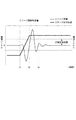
次に、基板ステージ9の移動方向と、残膜傾向情報との関係について説明する。基板ステージ9は、その制御指令(時間に対する目標位置を示す指令)に対して応答遅れを伴って位置決めされるものである。図4は、横軸は時間、実線のグラフに対応する縦軸は基板ステージ9の位置、点線のグラフに対応する縦軸はステージ偏差(制御指令に対する基板ステージ9の位置のずれ)を示している。例えば、時刻t1で移動し、時刻t2で停止するように指示を受けた基板ステージ9は、時刻t2でも整定せず、時刻t3でステージ偏差が許容範囲に収束する様子を示している。
Next, the relationship between the moving direction of the
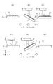
図5は、基板ステージ9の移動方向と傾きを示す図である。図5(A)、(D)は時刻t1〜t2の基板ステージ9の様子、図5(B)、(E)は時刻t2〜t3の基板ステージ9の様子、図5(C)(F)は時刻t3以降の様子を示している。図5(B)(E)に示すように、+X方向に移動する基板ステージ9は+X方向側が反対側に比べて下がるように、−X方向に移動する基板ステージ9は−X方向側が反対側に比べて下がるように、微小に傾く傾向がある。
FIG. 5 is a diagram showing the moving direction and inclination of the
本実施形態では、制御部17は、スループットを優先させて時刻t2〜t3に押印動作を行うように原版ステージ6を制御する。この場合、作成部18が後述の方法を用いて液滴パターンを作成しない場合は、基板3が移動方向側に傾いた状態で樹脂2と原版7が接触して(図6(A)(B))、パターン形成後の樹脂(以下、樹脂パターンという)2aの下部には、厚み偏差の大きな残膜2bが形成されてしまう(図6(C)(D))。残膜2bとは、押印により形成された樹脂パターン2aの下部(凹部)に残る層状部分のことを意味する。
In the present embodiment, the
第1実施形態で使用する基板ステージ9の移動方向情報は、基板ステージ9が、ディスペンサ15の下方位置から押印動作が行われる位置に向かう方向である。すなわちインプリント装置1の場合は、+X方向である。第1実施形態の残膜傾向情報は、ショット領域20内の移動方向側(+X方向側)の残膜2bが、当該移動方向側とは反対側(−X方向側)の残膜2bよりも厚くなる、という情報である(図5、図6参照)。
The movement direction information of the
(液滴パターンの作成方法)
残膜2bの膜厚のばらつき、すなわち膜厚分布を低減するための、第1実施形態に係る液滴パターンの作成工程100について図7を用いて説明する。基板ステージ9の移動方向に応じて生じるパターンの残膜2bの膜厚分布を低減できる液滴配置パターンを作成する方法である。
(Droplet pattern creation method)
A droplet
図7は液滴パターンの作成方法を示すフローチャートである。作成部18は、液滴パターンの作成に必要な情報、すなわち、原版情報、ディスペンサ情報、押印雰囲気の情報等を取得する(S101)。S101で取得した情報に基づいて、作成部18は、1つのショット領域20内の小領域ごとに必要となる樹脂量の目安を示す、樹脂量分布を作成する(S102)。
FIG. 7 is a flowchart showing a method for creating a droplet pattern. The creating
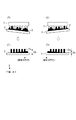
作成部は、ディスペンサ15の液滴サイズ情報を用いて、1回の押印あたりに必要な樹脂2の液滴数を算出する(S103)。液滴数を適当に配分し、予備液滴パターンを求める(S108)。予備液滴パターンの一例を図8(A)に示す。表示領域は、1つのショット領域20に対応する領域である。白地の矩形領域21は樹脂2を塗布しない領域を示し、黒地の矩形領域22は樹脂2を塗布する領域を示している。
The creation unit calculates the number of droplets of the
図7の説明に戻る。次に、作成部18は、基板ステージ9の移動方向情報と、当該移動方向情報に対応する残膜傾向情報とを格納部19から取得する(S105)。S105で取得した残膜傾向情報と予備液滴パターンを用いて、ディスペンサ15に設定するための液滴パターンを作成する(S107)。S107で作成する液滴パターンは、予備液滴パターンが示す樹脂2の総液滴数は変えず、その塗布位置の分布を変更したものである。
Returning to the description of FIG. Next, the
作成部18が図8(B)に示すような液滴パターンを作成する。残膜2bが厚くなりやすい移動方向側(移動先に近い側)に塗布する樹脂2の密度(供給量密度)が、残膜2bが薄くなりやすい移動方向側とは反対側(移動先から遠い側)に塗布する樹脂2の密度よりも小さくなるように樹脂2を塗布する液滴パターンである。S107で作成された液滴パターンに基づいて樹脂2を塗布することで、形成されるパターンの残膜2bの膜厚分布を低減することができる。
The creating
仮に、ディスペンサ15が原版7に対して+X方向側にあり、樹脂2の塗布された基板3が−X方向に移動しながら押印位置に到達する場合は、別の液滴パターンを作成する。図8(C)は、移動方向が−X方向の場合の液滴パターンを示す図である。移動方向が−X方向の場合も、残膜2bが厚くなりやすい移動方向側に塗布する樹脂2の密度が、残膜2bが薄くなりやすい移動方向側とは反対側に塗布する樹脂2の密度よりも小さくなるように樹脂を塗布できる液滴パターンを作成する。
If the
作成部18は、1種類の原版情報に対応する液滴パターンを複数作成する。原版7の凹凸パターンの一部領域が基板3からはみ出るように押印する場合があり、はみ出る部分に対応する位置には樹脂2を吐出しないようにできる液滴パターンも作成する必要があるからである。
The creating
(インプリント処理の流れ)
次に、インプリント処理の流れについて、図9、図10を用いて説明する。図9はインプリント処理の流れを示すフローチャートである。図10は、インプリント処理の様子を示す図である。制御部17が図9のフローチャートに示すプログラムを実行することでインプリント処理が行われる。
(Imprint process flow)
Next, the flow of imprint processing will be described with reference to FIGS. FIG. 9 is a flowchart showing the flow of imprint processing. FIG. 10 is a diagram illustrating a state of imprint processing. The imprint process is performed when the
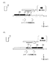
まず、作成部18が前述の流れで作成部18が液滴配置パターンを作成する(S100)。搬送機構(不図示)が、所望の凹凸パターンが形成された原版7を原版ステージ6に搭載させる(S200)。
First, the creating
制御部17は、原版7の原版情報を取得し、当該原版7に対応する液滴パターンのセットを取得する(S300)。液滴パターンのセットには、複数の液滴パターンが含まれている。制御部17は、パターンを形成するショット領域20を選択し、当該ショット領域20の移動方向から、対応する液滴パターンを選択してディスペンサ15に設定する(S300)。
The
ディスペンサ15が、設定された液滴パターンに従って、基板3上に未硬化の樹脂2を塗布する(S400)(図10(A))。ディスペンサ15の位置から押印位置まで基板3が移動したら、所定のタイミングで原版7を樹脂2に押印する(S500)(図10(B))。所定のタイミングとは、ステージ偏差が許容範囲に達する前のタイミング(時刻t2〜t3)である。
The
原版7の凹部に樹脂2が充填された後(図10(C))に、光源5が紫外光4を所定時間照射して、未硬化状態の樹脂2を硬化させる(S600)(図10(D))。原版ステージ6が、原版7を離型する(S700)(図10(E))。このようにして、基板3上に樹脂2パターン2aが形成される。
After the
作成部18が作成した液滴パターンは、残膜傾向情報に基づいて作成されたものである。ディスペンサ15が、残膜2bの膜厚分布を低減するように作成された液滴パターンを用いて樹脂2を塗布することによって、樹脂パターン2aの残膜2bの膜厚はほぼ均一となる。制御部17は、基板3上の全ショット領域20にパターンを形成し終えたかどうかを判断する(S800)。パターンを形成した(Yes)場合は、制御部17は基板3を搬出させる(S1000)。
The droplet pattern created by the
まだパターンの形成されていないショット領域20がある場合は(No)、次のショット領域20を選択し、そのショット領域20を押印する際に液滴パターンの変更が必要かどうかを判断する(S900)。
If there is a
変更が必要な場合とは、例えば、次に押印するショット領域20の移動方向が先に押印したショット領域20の移動方向とは異なる場合、あるいは、原版7の凹凸パターンの一部領域が基板3からはみ出るように押印する場合である。液滴パターンの変更が必要な場合は、再び適切な液滴パターンを選択し(S300)、S400〜S900を繰り返す。変更が不要な場合は、同じ液滴パターンに基づいてS400〜S900を繰り返す。後続の基板3、後続する別のロットの基板3に対しても、制御部17により選択された適切な液的パターンを用いてパターンを形成する。
The change is necessary when, for example, the movement direction of the
所定のショット領域20ごと、または1枚の基板3を処理するごとに、インプリント装置1の内部あるいは外部において、パターンの欠陥情報検査や異常検知情報を取得し、液滴パターンを選択しなおしてもよい。あるいは新たな液滴パターンを作成してもよい。欠陥情報とは、検査装置(不図示)で得られた樹脂2パターンの転写精度の測定結果である。異常検知情報とは、ディスペンサ15による液滴配置精度の異常、型の押印力または離型力の異常、押印時の不純物噛み、原版7の規定の使用回数を超え等の情報である。
Every time a
以上のように、第1実施形態では、作成部18が、基板ステージ9の水平方向の移動方向情報、および当該移動方向情報と相関のある残膜傾向情報に基づいて液滴パターンを作成する。そして、作成部18が作成した液滴パターンにしたがってディスペンサ15が樹脂2を塗布する。スループットを優先して基板3が整定状態になる前に押印する場合であっても、本実施形態を実施しない場合に比べて、形成後の樹脂2パターンにおける残膜2bの膜厚分布を低減することができる(残膜の膜厚の均一性を向上させることができる)。
As described above, in the first embodiment, the
また、残膜傾向情報を予め格納部19に記憶させていることにより、ステージ9が新しい移動方向に移動しながら押印位置に到着する場合であっても、作成部18は残膜の膜厚計測を介さずに残膜偏差を低減できる液滴パターンを作成することができる。これにより、少なくとも、最初のインプリント処理後の1回分の残膜2bの計測時間を短縮することができる。
Further, since the remaining film tendency information is stored in the
なお、基板ステージ9の移動方向情報は、樹脂2の塗布された基板3が、ディスペンサ15の下方位置を離れて最短距離で押印位置に向かわない場合は、移動の最後に、ある位置から押印位置に向かう移動方向であってもよい。
Note that the movement direction information of the
[第2実施形態]
基板ステージ9の速度大きさの大小によって、押印位置における基板ステージ9の傾きが異なる。第2実施形態では、作成部18は、基板ステージ9の移動方向と、当該移動方向とから予測される残膜傾向情報と、基板ステージ9が水平面に沿って移動するときの速さに関する情報とにも基づいて、供給量密度の偏差が異なる液滴パターンを作成する。
[Second Embodiment]
The inclination of the
基板ステージ9の速さに関する情報とは、速度の大きさあるいは加速度等の大きさを示す情報である。基板ステージ9の速さに関する情報にも基づいて作成された液滴パターン作成すれば、押印位置における基板ステージ9の傾きが速さに関する情報に応じて変化する場合にも、残膜2bが同程度の膜厚分布となるようにすることができる。
The information related to the speed of the
作成部18は、第1実施形態で示した図7のS105において速さに関する情報も取得し、これに基づいて液滴パターンを作成する。例えば、基板ステージ9が速く移動する場合の液滴パターンは、当該場合よりも遅く移動する場合の液滴パターンに比べて、供給量の密な領域と疎な領域との密度差が大きな(供給量密度の差が大きな)液滴パターンとなる。
The
[第3実施形態]
第3実施形態では、インプリント材の状態に関する情報とは、残膜傾向情報である。あるいは、残膜傾向情報と相関のある、基板ステージ9の移動中の樹脂2の状態でもよい。例えば、基板3に塗布された各液滴の体積が揮発によりどのように変化するかを示す傾向である。
[Third Embodiment]
In the third embodiment, the information regarding the state of the imprint material is residual film tendency information. Alternatively, the state of the
本実施形態では、パターンの形成順序に関する情報は、押印順序である。図3(A)(B)に示すように、それぞれのショット領域20に対して何番目にパターンが形成されるのか、という情報である。
In the present embodiment, the information regarding the pattern formation order is the stamp order. As shown in FIGS. 3A and 3B, this is information indicating how many patterns are formed for each shot
第3実施形態に係るインプリント装置1は、作成部18は、押印順序と、残膜傾向情報に基づいて液滴パターンを作成する。ディスペンサ15と対向する位置から押印位置に向かう方向が一定であっても、インプリント装置内の気流の影響や、基板ステージ9の移動に伴う気流の影響等を受けて、その押印順序によって残膜傾向が一定とはならない場合に有利な実施形態である。
In the
図11は、図3(B)に示すような押印順序で樹脂パターン2aを形成する場合の、押印順序と残膜傾向情報の関係を示す図である。複数のショット領域20のそれぞれに描かれている円の大きさは、残膜2bの膜厚の厚さに対応している。すなわち、円の大きな領域ほど、残膜2bの膜厚が厚くなる領域を示している。
FIG. 11 is a diagram showing the relationship between the stamping order and the remaining film tendency information when the
図12(A)(B)は押印順序と、パターンの形成状況との関係を示す図である。ショット領域23(第1領域)は、パターンが形成されておらず、かつ樹脂2の塗布されたショット領域、ショット領域(第2領域)24は樹脂パターン2aが形成されたショット領域である。ショット領域23上の樹脂2は、基板ステージ9の移動によって、液滴の状態が揮発により変化した様子を示している。
12A and 12B are diagrams showing the relationship between the stamping order and the pattern formation status. The shot area 23 (first area) is a shot area where no pattern is formed and the
図11の1行目では、基板ステージ9の移動方向側(+X方向側)に順にパターンが形成されていく。すなわち、図12(A)に示すように、ショット領域23がショット領域24に対して、基板ステージ9の移動方向側にある状態で、基板ステージ9は移動する。この場合は、残膜傾向情報は、基板ステージ9の移動方向側における残膜2bの膜厚が、当該移動方向側とは反対側の膜厚よりも厚くなりやすいという情報になる。
In the first row of FIG. 11, patterns are sequentially formed on the movement direction side (+ X direction side) of the
図11の2行目は、移動方向とは逆方向(−X方向)に順にパターンが形成されていく。すなわち、図12(B)に示すように、ショット領域24がショット領域23に対して、基板ステージ9の移動方向側にある状態で、基板ステージ9は移動する。この場合は、残膜傾向情報は、基板ステージ9の移動方向側における残膜2bの膜厚が、当該移動方向側とは反対側の膜厚よりも薄くなりやすいという情報になる。
In the second row of FIG. 11, patterns are sequentially formed in the direction opposite to the moving direction (−X direction). That is, as shown in FIG. 12B, the
次に、第3実施形態にかかるインプリント装置1について説明する。第3実施形態にかかる格納部19は、押印順序と、押印順序と相関のある残膜傾向情報とを有している。本実施形態における残膜傾向情報は、押印順序や基板ステージ9の移動方向から予測される、残膜2bの膜厚分布の傾向である。基板ステージ9が許容範囲まで整定した状態において押印動作を行うもの実施形態とする。作成部18による液滴パターンの作成方法以外は、第1実施形態と同様のインプリント処理を行うため説明を省略する。
Next, an
作成部18は、押印順序(移動手段の移動によって変化するインプリント材の状態と相関のある情報)と、押印順序と相関のある残膜傾向情報に基づいて液滴パターンを作成する。
The creating
図11の1行目のように基板ステージ9の移動方向側に順にパターンを形成していく場合について説明する。作成部18は、残膜2bが厚くなりやすい移動方向側に塗布する樹脂2の密度が、残膜2bが薄くなりやすい移動方向側とは反対側に塗布する樹脂2の密度よりも小さくなるようにショット領域23内に樹脂を塗布できる液滴パターン(図8(B)参照)を作成する。すなわち、ショット領域23がショット領域24に対して基板ステージ9が移動する移動方向側とは反対側にある状態において、移動方向側に塗布される樹脂2の密度が、当該移動方向側とは反対側に塗布される樹脂2の密度よりも小さくなるような液滴パターン(第2供給量分布)を作成する。
A case will be described in which a pattern is sequentially formed on the moving direction side of the
図11の2行目のように基板ステージ9の移動方向側と反対方向に順にパターンを形成していく場合について説明する。作成部18は、残膜2bが薄くなりやすい移動方向側に塗布する樹脂2の密度が、残膜2bが厚くなりやすい移動方向側とは反対側に塗布する樹脂2の密度よりも大きくなるようにショット領域23内に樹脂2を塗布できる液滴パターン(第1供給量分布)(図13)を作成する。すなわち、ショット領域23がショット領域24に対して基板ステージ9が移動する移動方向側にある状態において、移動方向側に塗布される樹脂2の密度が、当該移動方向側とは反対側に塗布される樹脂2の密度よりも大きくなるような液滴パターンを作成する。
A case will be described in which a pattern is sequentially formed in the direction opposite to the moving direction side of the
作成部18が押印順序と残膜傾向情報に基づいて、液滴パターンを作成することにより、押印順序に起因して残膜傾向状況が異なる場合にも、残膜2bの膜厚分布が低減されるような液滴パターンを作成できる。
The
なお、パターンの形成順序に関する情報は、ショット領域23とショット領域24との位置関係を把握できるような情報であればよい。そのため、押印順序以外の情報でもよい。
Note that the information related to the pattern formation order may be information that can grasp the positional relationship between the shot
たとえば、n回目にパターンを形成したショット領域20と、n+1回目にパターンを形成しようとするショット領域20の位置を比較し、n回目にパターンを形成したショット領域20からn+1回目にパターンを形成したショット領域に向かう方向が、基板ステージ9の移動方向と同じか否か、という情報(連続して形成されるパターンの位置関係)でもよい。基板ステージ9の移動方向側に、ショット領域24が存在するか否か、という情報(第1領域の移動方向側における第2領域の有無情報)でもよい。さらに、XY平面内にどの位置にショット領域24が配置されているかという情報(第2領域の位置情報)でもよい。
For example, the position of the
作成部18は、さらに、押印位置周囲の空気を不活性ガスを供給する部材(不図示)の配置に基づいて、液滴パターンを作成してもよい。さらに、押印位置に到達するまでの基板ステージ9の移動距離及び移動方向に基づいて液滴パターンを作成してもよい。第2実施形態と同様に、基板ステージ9の速さに関する情報にも基づいて液滴パターンを作成してもよい。押印順序は図3に示したものに限られない。ランダムな押印順序、千鳥格子模様となる押印順序などでもよい。
The
[その他の実施形態]
以下、本発明にかかるその他の実施形態について説明する。
[Other Embodiments]
Hereinafter, other embodiments according to the present invention will be described.
インプリント装置1が、ディスペンサ15を複数備えていてもよい。ディスペンサ15が複数ある場合は、押印対象となるショット領域20に対して樹脂2を塗布したディスペンサ15と対向する位置から、押印位置へ向かう方向が基板ステージ9の移動方向となる。作成部18が、それぞれの移動に関する情報から得られる樹脂の残膜傾向情報に基づいて適切な液滴パターンを作成する。
The
基板3におけるショット領域23の位置に応じて使用するディスペンサ15が異なり、残膜傾向情報の種類が増える場合であっても、ショット領域20内の残膜2bの膜厚分布、及びショット領域20間の残膜2bの膜厚分布を低減することができる。
Even if the
移動方向は、押印対象となるショット領域20の基板上での位置、ディスペンサ15の位置、押印位置によって定まるものである。作成部18がこれらの情報に基づいて求めたものでもよいし、制御部17が求めた上で格納部19に格納したものを用いてもよい。
The moving direction is determined by the position of the
作成部18はインプリント装置1の外部にあってもよい。作成部18が作成した液滴パターンのデータが、記憶情報媒体や有線または無線通信によりメモリ23に供給されてもよい。制御部17、格納部19、作成部18は、前述のそれぞれの機能を有しているのであれば、一つの制御基板上に設けられていても、別個の制御基板上に設けられていてもよい。
The creating
残膜2bの膜厚分布を低減するために、第1〜第3の実施形態に示した液滴パターンの作成方法と、原版7の傾きを調整する方法と組み合わせてもよい。この場合は、原版7の傾き度合いを変更した際に、作成部18が液滴パターンにおける樹脂2の塗布密度の偏差を変更する。
In order to reduce the film thickness distribution of the remaining
第1〜第3の実施形態では、紫外光4を照射することで光硬化性の樹脂2を硬化させる光インプリント法を説明したが、これに限るものではない。インプリント材として、光を含む各種電磁放射線により硬化する樹脂を用いたインプリント法であっても、加熱により硬化する樹脂を用いた熱インプリント法であってもよい
[物品の製造方法]
本発明の実施形態にかかる物品(半導体集積回路素子、液晶表示素子、撮像素子、磁気ヘッド、CD−RW、光学素子、フォトマスク等)の製造方法は、インプリント装置1を用いて基板(単結晶シリコンウエハ、SOI(Silicon on Insulator)、ガラス板等)3上にパターンを形成する工程と、当該パターンが形成された基板3に対してエッチング処理及びイオン注入処理の少なくともいずれか一方の処理を施す工程とを含む。さらに、他の周知の処理工程(酸化、成膜、蒸着、平坦化、レジスト剥離、ダイシング、ボンディング、パッケージング等)を含んでもよい。
In the first to third embodiments, the photoimprint method of curing the
A method for manufacturing an article (a semiconductor integrated circuit element, a liquid crystal display element, an image sensor, a magnetic head, a CD-RW, an optical element, a photomask, etc.) according to an embodiment of the present invention uses a substrate (single unit) using the
以上、本発明の好ましい実施例について説明したが、本発明はこれらの実施例に限定さ
れないことはいうまでもなく、その要旨の範囲内で種々の変形及び変更が可能である。
The preferred embodiments of the present invention have been described above, but the present invention is not limited to these embodiments, and various modifications and changes can be made within the scope of the gist.
1 インプリント装置
2 樹脂(インプリント材)
3 基板
8 原版(型)
9 基板ステージ(移動手段)
15 ディスペンサ(供給手段)
18 作成部(作成手段)
20 ショット領域(領域)
23 ショット領域(第2領域)
24 ショット領域(第1領域)
1
3
9 Substrate stage (moving means)
15 Dispenser (supply means)
18 Production Department (Creation means)
20 shot area (area)
23 Shot area (second area)
24 shot area (first area)
Claims (5)
前記基板上にインプリント材を供給する供給手段と、
前記基板を載せて移動する移動手段と、
前記移動手段が、前記供給手段が前記基板上にインプリント材を供給する位置から、前記型を前記インプリント材に接触させる位置に向かうときの移動方向と、前記複数のショット領域の位置関係と押印順序に関する情報と、前記押印順序の違いによって生じる前記インプリント材のパターンの残膜の膜厚分布の傾向を示す残膜傾向情報あるいは前記残膜分布の傾向と相関のある情報と、に基づいて、前記基板のショット領域の各々に供給される前記インプリント材の供給量分布を作成する作成手段と、を有し、
前記作成手段は、前記複数のショット領域のうち、パターンがすでに形成されているショット領域の前記移動方向側に隣接する第1ショット領域への前記インプリント材の供給量分布が、前記パターンがすでに形成されているショット領域の前記移動方向とは反対側に隣接する第2ショット領域への前記インプリント材の供給量分布とは異なるように、前記供給量分布を作成し、
前記供給手段は、前記作成手段が作成した供給量分布に基づいて、前記インプリント材を前記基板上に供給することを特徴とするインプリント装置。 Upon depression order of a plurality of shot regions of the substrate, the type of pattern, is brought into contact with the imprint material on each of the plurality of shot regions of the substrate, forming a pattern in a plurality of shot regions of the substrate An imprinting device,
Supply means for supplying an imprint material on the substrate;
A moving means for moving by placing said substrate,
The moving means moves from the position where the supply means supplies the imprint material onto the substrate to the position where the mold contacts the imprint material, and the positional relationship between the plurality of shot areas. Based on the information on the stamping order and the residual film tendency information indicating the tendency of the film thickness distribution of the residual film of the pattern of the imprint material caused by the difference in the stamping order or the information correlated with the tendency of the residual film distribution Creating a supply amount distribution of the imprint material supplied to each of the shot areas of the substrate ,
The creation means includes a distribution amount of the imprint material to a first shot area adjacent to the moving direction side of a shot area in which a pattern is already formed among the plurality of shot areas, and the pattern is already The supply amount distribution is created so as to be different from the supply amount distribution of the imprint material to the second shot region adjacent to the opposite side of the moving direction of the shot region being formed,
The imprint apparatus , wherein the supply means supplies the imprint material onto the substrate based on a supply amount distribution created by the creation means .
前記第1ショット領域に対し、領域内において前記移動方向側の供給量密度が、前記移動方向側とは反対側の供給量密度よりも大きくなるように第1供給量分布を作成し、
前記第2ショット領域に対し、領域内において前記移動方向とは反対側の供給量密度が、前記移動方向側の供給量密度よりも大きくなるように第2供給量分布を作成し、
前記供給手段は、前記第1供給量分布に基づいて前記第1ショット領域に対して前記インプリント材を供給し、前記第2供給量分布に基づいて前記第2ショット領域に対して前記インプリント材を供給することを特徴とする請求項1に記載のインプリント装置。 The creating means includes
For the first shot region, create a first supply amount distribution so that the supply amount density on the moving direction side in the region is larger than the supply amount density on the opposite side to the moving direction side,
A second supply amount distribution is created so that the supply amount density on the side opposite to the movement direction in the region is larger than the supply amount density on the movement direction side with respect to the second shot region,
The supply means supplies the imprint material to the first shot region based on the first supply amount distribution, and the imprint to the second shot region based on the second supply amount distribution. The imprint apparatus according to claim 1, wherein a material is supplied .
前記基板上にインプリント材を供給する位置から、前記型を前記インプリント材に接触させる位置に向かうときの前記基板の移動方向と、前記複数のショット領域の位置関係と押印順序に関する情報と、前記押印順序の違いによって生じる前記インプリント材のパターンの残膜の膜厚分布の傾向を示す残膜傾向情報あるいは前記残膜分布の傾向と相関のある情報とを取得するステップと、
前記ステップで取得した情報に基づいて、前記インプリント材の供給量分布を作成するステップと、を有し、
前記作成するステップにおいて、前記複数のショット領域のうち、パターンがすでに形成されているショット領域の前記移動方向側に隣接する第1ショット領域への前記インプリント材の供給量分布が、前記パターンがすでに形成されているショット領域の前記移動方向とは反対側に隣接する第2ショット領域への前記インプリント材の供給量分布とは異なるように、前記供給量分布を作成することを特徴とする供給量分布の作成方法。 A pattern is formed in the plurality of shot regions of the substrate by contacting the pattern of the mold with the imprint material on each of the plurality of shot regions of the substrate according to the order of stamping the plurality of shot regions of the substrate. A method of creating a supply amount distribution of the imprint material when
Information on the moving direction of the substrate when moving from the position for supplying the imprint material onto the substrate to the position where the mold is brought into contact with the imprint material, the positional relationship between the plurality of shot regions, and the stamping order, Obtaining the residual film tendency information indicating the tendency of the film thickness distribution of the residual film of the pattern of the imprint material caused by the difference in the stamping order or information correlated with the tendency of the residual film distribution ;
Based on the information obtained in the step, have a, creating a supply amount distribution of the imprint material,
In the creating step, the supply amount distribution of the imprint material to the first shot region adjacent to the moving direction side of the shot region in which a pattern is already formed among the plurality of shot regions, The supply amount distribution is created so as to be different from the supply amount distribution of the imprint material to the second shot region adjacent to the opposite side to the moving direction of the shot region that has already been formed. How to create a supply distribution.
前記基板上にインプリント材を供給する位置から、前記型を前記インプリント材に接触させる位置に向かうときの前記基板の移動方向と、前記複数のショット領域の位置関係と押印順序に関する情報と、前記押印順序の違いによって生じる前記インプリント材のパターンの残膜の膜厚分布の傾向を示す残膜傾向情報あるいは前記残膜分布の傾向と相関のある情報と、に基づいて、前記基板のショット領域の各々に供給される前記インプリント材の供給量分布を決定するステップと、
前記決定された供給量分布に基づいて、インプリント材を前記基板上に供給するステップを含み、
前記決定するステップにおいて、前記複数のショット領域のうち、パターンがすでに形成されているショット領域の前記移動方向側に隣接する第1ショット領域への前記インプリント材の供給量分布が、前記パターンがすでに形成されているショット領域の前記移動方向とは反対側に隣接する第2ショット領域への前記インプリント材の供給量分布とは異なるように、前記供給量分布を決定することを特徴とするインプリント方法。 Upon depression order of a plurality of shot regions of the substrate, the type of pattern, is brought into contact with the imprint material on each of the plurality of shot regions of the substrate, forming a pattern in a plurality of shot regions of the substrate An imprint method for
Information on the moving direction of the substrate when moving from the position for supplying the imprint material onto the substrate to the position where the mold is brought into contact with the imprint material, the positional relationship between the plurality of shot regions, and the stamping order, The shot of the substrate based on the residual film tendency information indicating the tendency of the residual film thickness distribution of the pattern of the imprint material caused by the difference in the stamping order or the information correlated with the residual film distribution tendency Determining a supply amount distribution of the imprint material supplied to each of the regions ;
Based on the feed weight distribution said determined look including the step of providing the imprint material on the substrate,
In the determining step, the supply amount distribution of the imprint material to the first shot region adjacent to the moving direction side of the shot region in which a pattern has already been formed among the plurality of shot regions, The supply amount distribution is determined so as to be different from the supply amount distribution of the imprint material to the second shot region adjacent to the side opposite to the movement direction of the shot region that has already been formed. Imprint method.
前記パターンの形成された基板に対してエッチング処理及びイオン注入処理のいずれか一方の処理を施すステップと、を有することを特徴とする物品の製造方法。 A step of forming a pattern on the substrate using the supply amount distribution of the imprint material obtained by the production method according to claim 3 ;
Performing a process of any one of an etching process and an ion implantation process on the substrate on which the pattern is formed.
Priority Applications (4)
| Application Number | Priority Date | Filing Date | Title |
|---|---|---|---|
| JP2015074495A JP6602033B2 (en) | 2015-03-31 | 2015-03-31 | Imprint apparatus, supply amount distribution generation method, imprint method, and article manufacturing method |
| US15/082,985 US20160291486A1 (en) | 2015-03-31 | 2016-03-28 | Imprinting apparatus, method of creating data on material distribution, imprinting method, and article manufacturing method |
| KR1020160038093A KR102055972B1 (en) | 2015-03-31 | 2016-03-30 | Imprinting apparatus, method of creating data on material distribution, imprinting method, and article manufacturing method |
| CN201610195961.1A CN106019824A (en) | 2015-03-31 | 2016-03-31 | Imprinting apparatus, imprinting method, method of creating data on material distribution, and article manufacturing method |
Applications Claiming Priority (1)
| Application Number | Priority Date | Filing Date | Title |
|---|---|---|---|
| JP2015074495A JP6602033B2 (en) | 2015-03-31 | 2015-03-31 | Imprint apparatus, supply amount distribution generation method, imprint method, and article manufacturing method |
Publications (3)
| Publication Number | Publication Date |
|---|---|
| JP2016195184A JP2016195184A (en) | 2016-11-17 |
| JP2016195184A5 JP2016195184A5 (en) | 2018-05-17 |
| JP6602033B2 true JP6602033B2 (en) | 2019-11-06 |
Family
ID=57015896
Family Applications (1)
| Application Number | Title | Priority Date | Filing Date |
|---|---|---|---|
| JP2015074495A Active JP6602033B2 (en) | 2015-03-31 | 2015-03-31 | Imprint apparatus, supply amount distribution generation method, imprint method, and article manufacturing method |
Country Status (4)
| Country | Link |
|---|---|
| US (1) | US20160291486A1 (en) |
| JP (1) | JP6602033B2 (en) |
| KR (1) | KR102055972B1 (en) |
| CN (1) | CN106019824A (en) |
Families Citing this family (2)
| Publication number | Priority date | Publication date | Assignee | Title |
|---|---|---|---|---|
| US11131923B2 (en) * | 2018-10-10 | 2021-09-28 | Canon Kabushiki Kaisha | System and method of assessing surface quality by optically analyzing dispensed drops |
| JP7286400B2 (en) * | 2019-04-24 | 2023-06-05 | キヤノン株式会社 | Molding Apparatus, Determining Method, and Article Manufacturing Method |
Family Cites Families (16)
| Publication number | Priority date | Publication date | Assignee | Title |
|---|---|---|---|---|
| JP2005101201A (en) * | 2003-09-24 | 2005-04-14 | Canon Inc | Nano-imprint system |
| US20070228593A1 (en) * | 2006-04-03 | 2007-10-04 | Molecular Imprints, Inc. | Residual Layer Thickness Measurement and Correction |
| CN101604124B (en) * | 2005-06-08 | 2011-07-27 | 佳能株式会社 | Mold, pattern forming method, and pattern forming apparatus |
| US8011916B2 (en) * | 2005-09-06 | 2011-09-06 | Canon Kabushiki Kaisha | Mold, imprint apparatus, and process for producing structure |
| JP4908369B2 (en) * | 2007-10-02 | 2012-04-04 | 株式会社東芝 | Imprint method and imprint system |
| JP5361309B2 (en) * | 2008-09-25 | 2013-12-04 | キヤノン株式会社 | Imprint apparatus and imprint method |
| JP2010239118A (en) * | 2009-03-11 | 2010-10-21 | Canon Inc | Imprint apparatus and method |
| JP5563243B2 (en) * | 2009-06-01 | 2014-07-30 | キヤノン株式会社 | Imprint apparatus and article manufacturing method |
| JP2010283207A (en) * | 2009-06-05 | 2010-12-16 | Toshiba Corp | Pattern forming device and pattern forming method |
| JP2011061029A (en) * | 2009-09-10 | 2011-03-24 | Canon Inc | Imprinting method and imprinting apparatus |
| JP5744422B2 (en) * | 2010-06-17 | 2015-07-08 | キヤノン株式会社 | Imprint method, imprint apparatus, sample shot extraction method, and article manufacturing method using the same |
| JP5214683B2 (en) * | 2010-08-31 | 2013-06-19 | 株式会社東芝 | Imprint recipe creating apparatus and method, and imprint apparatus and method |
| JP5337776B2 (en) * | 2010-09-24 | 2013-11-06 | 富士フイルム株式会社 | Nanoimprint method and substrate processing method using the same |
| JP2012114157A (en) * | 2010-11-22 | 2012-06-14 | Toshiba Corp | Drop recipe preparation method and database generating method |
| CN103624992B (en) * | 2013-11-22 | 2016-05-25 | 北京化工大学 | A kind of sheet material press device and press working method of polymer micro-structural |
| JP6313591B2 (en) * | 2013-12-20 | 2018-04-18 | キヤノン株式会社 | Imprint apparatus, foreign matter removing method, and article manufacturing method |
-
2015
- 2015-03-31 JP JP2015074495A patent/JP6602033B2/en active Active
-
2016
- 2016-03-28 US US15/082,985 patent/US20160291486A1/en not_active Abandoned
- 2016-03-30 KR KR1020160038093A patent/KR102055972B1/en active IP Right Grant
- 2016-03-31 CN CN201610195961.1A patent/CN106019824A/en active Pending
Also Published As
| Publication number | Publication date |
|---|---|
| US20160291486A1 (en) | 2016-10-06 |
| JP2016195184A (en) | 2016-11-17 |
| KR20160117322A (en) | 2016-10-10 |
| KR102055972B1 (en) | 2019-12-13 |
| CN106019824A (en) | 2016-10-12 |
Similar Documents
| Publication | Publication Date | Title |
|---|---|---|
| JP6611450B2 (en) | Imprint apparatus, imprint method, and article manufacturing method | |
| US10168615B2 (en) | Imprint apparatus, imprint method, and article manufacturing method | |
| KR20100035111A (en) | Imprint apparatus and method of manufacturing article | |
| TWI603376B (en) | Imprint apparatus, and method of manufacturing article | |
| JP6306830B2 (en) | Imprint apparatus and article manufacturing method | |
| JP6120677B2 (en) | Imprint apparatus, imprint method, and article manufacturing method | |
| US20150360400A1 (en) | Imprint method, imprint apparatus, and article manufacturing method | |
| JP6714378B2 (en) | Imprint apparatus and article manufacturing method | |
| JP7100436B2 (en) | Imprint device and article manufacturing method | |
| US10120276B2 (en) | Imprint apparatus, imprint method, and method of manufacturing article | |
| JP6602033B2 (en) | Imprint apparatus, supply amount distribution generation method, imprint method, and article manufacturing method | |
| JP2020194891A (en) | Lithographic apparatus and manufacturing method of goods | |
| US11422459B2 (en) | Data generation method, imprint method, imprint apparatus, and method of manufacturing article | |
| JP2015079887A (en) | Imprint device and method of manufacturing article | |
| KR102316813B1 (en) | Imprint apparatus, imprint method and article manufacturing method | |
| US11231648B2 (en) | Imprint device, imprint method, and method for manufacturing article | |
| US11833719B2 (en) | Imprint apparatus, imprint method, and method for manufacturing article | |
| US20220063175A1 (en) | Substrate processing method, substrate holding apparatus, molding apparatus, and article manufacturing method | |
| JP6938247B2 (en) | Imprint method, imprint device, and article manufacturing method | |
| KR20220165650A (en) | Molding apparatus, molding method, and article manufacturing method | |
| JP2022091479A (en) | Formation device, formation method, and method for manufacturing article | |
| KR20190027911A (en) | Imprint apparatus and article manufacturing method |
Legal Events
| Date | Code | Title | Description |
|---|---|---|---|
| A521 | Written amendment |
Free format text: JAPANESE INTERMEDIATE CODE: A523 Effective date: 20180328 |
|
| A621 | Written request for application examination |
Free format text: JAPANESE INTERMEDIATE CODE: A621 Effective date: 20180328 |
|
| A977 | Report on retrieval |
Free format text: JAPANESE INTERMEDIATE CODE: A971007 Effective date: 20190225 |
|
| A131 | Notification of reasons for refusal |
Free format text: JAPANESE INTERMEDIATE CODE: A131 Effective date: 20190312 |
|
| A521 | Written amendment |
Free format text: JAPANESE INTERMEDIATE CODE: A523 Effective date: 20190511 |
|
| TRDD | Decision of grant or rejection written | ||
| A01 | Written decision to grant a patent or to grant a registration (utility model) |
Free format text: JAPANESE INTERMEDIATE CODE: A01 Effective date: 20190910 |
|
| A61 | First payment of annual fees (during grant procedure) |
Free format text: JAPANESE INTERMEDIATE CODE: A61 Effective date: 20191008 |
|
| R151 | Written notification of patent or utility model registration |
Ref document number: 6602033 Country of ref document: JP Free format text: JAPANESE INTERMEDIATE CODE: R151 |