JP6601345B2 - Vehicle control device - Google Patents
Vehicle control device Download PDFInfo
- Publication number
- JP6601345B2 JP6601345B2 JP2016163907A JP2016163907A JP6601345B2 JP 6601345 B2 JP6601345 B2 JP 6601345B2 JP 2016163907 A JP2016163907 A JP 2016163907A JP 2016163907 A JP2016163907 A JP 2016163907A JP 6601345 B2 JP6601345 B2 JP 6601345B2
- Authority
- JP
- Japan
- Prior art keywords
- collision
- actuator
- vehicle
- steering
- control
- Prior art date
- Legal status (The legal status is an assumption and is not a legal conclusion. Google has not performed a legal analysis and makes no representation as to the accuracy of the status listed.)
- Active
Links
- 230000008859 change Effects 0.000 claims description 11
- 238000004364 calculation method Methods 0.000 claims description 6
- 238000013021 overheating Methods 0.000 claims 1
- 238000000034 method Methods 0.000 description 51
- 230000008569 process Effects 0.000 description 44
- 230000000694 effects Effects 0.000 description 13
- 238000004891 communication Methods 0.000 description 12
- 238000001514 detection method Methods 0.000 description 12
- 239000000470 constituent Substances 0.000 description 9
- 230000006870 function Effects 0.000 description 8
- 238000012545 processing Methods 0.000 description 7
- 102100022840 DnaJ homolog subfamily C member 7 Human genes 0.000 description 3
- 102100029211 E3 ubiquitin-protein ligase TTC3 Human genes 0.000 description 3
- 101000903053 Homo sapiens DnaJ homolog subfamily C member 7 Proteins 0.000 description 3
- 101000633723 Homo sapiens E3 ubiquitin-protein ligase TTC3 Proteins 0.000 description 3
- 101000847024 Homo sapiens Tetratricopeptide repeat protein 1 Proteins 0.000 description 3
- 102100032841 Tetratricopeptide repeat protein 1 Human genes 0.000 description 3
- 238000012937 correction Methods 0.000 description 3
- 230000004048 modification Effects 0.000 description 3
- 238000012986 modification Methods 0.000 description 3
- 239000004065 semiconductor Substances 0.000 description 2
- 238000010586 diagram Methods 0.000 description 1
- 230000008014 freezing Effects 0.000 description 1
- 238000007710 freezing Methods 0.000 description 1
- 230000000630 rising effect Effects 0.000 description 1
- 230000007704 transition Effects 0.000 description 1
Images


Classifications
-
- B—PERFORMING OPERATIONS; TRANSPORTING
- B60—VEHICLES IN GENERAL
- B60W—CONJOINT CONTROL OF VEHICLE SUB-UNITS OF DIFFERENT TYPE OR DIFFERENT FUNCTION; CONTROL SYSTEMS SPECIALLY ADAPTED FOR HYBRID VEHICLES; ROAD VEHICLE DRIVE CONTROL SYSTEMS FOR PURPOSES NOT RELATED TO THE CONTROL OF A PARTICULAR SUB-UNIT
- B60W30/00—Purposes of road vehicle drive control systems not related to the control of a particular sub-unit, e.g. of systems using conjoint control of vehicle sub-units
- B60W30/08—Active safety systems predicting or avoiding probable or impending collision or attempting to minimise its consequences
- B60W30/09—Taking automatic action to avoid collision, e.g. braking and steering
-
- B—PERFORMING OPERATIONS; TRANSPORTING
- B60—VEHICLES IN GENERAL
- B60R—VEHICLES, VEHICLE FITTINGS, OR VEHICLE PARTS, NOT OTHERWISE PROVIDED FOR
- B60R21/00—Arrangements or fittings on vehicles for protecting or preventing injuries to occupants or pedestrians in case of accidents or other traffic risks
-
- B—PERFORMING OPERATIONS; TRANSPORTING
- B60—VEHICLES IN GENERAL
- B60W—CONJOINT CONTROL OF VEHICLE SUB-UNITS OF DIFFERENT TYPE OR DIFFERENT FUNCTION; CONTROL SYSTEMS SPECIALLY ADAPTED FOR HYBRID VEHICLES; ROAD VEHICLE DRIVE CONTROL SYSTEMS FOR PURPOSES NOT RELATED TO THE CONTROL OF A PARTICULAR SUB-UNIT
- B60W10/00—Conjoint control of vehicle sub-units of different type or different function
- B60W10/18—Conjoint control of vehicle sub-units of different type or different function including control of braking systems
-
- B—PERFORMING OPERATIONS; TRANSPORTING
- B60—VEHICLES IN GENERAL
- B60W—CONJOINT CONTROL OF VEHICLE SUB-UNITS OF DIFFERENT TYPE OR DIFFERENT FUNCTION; CONTROL SYSTEMS SPECIALLY ADAPTED FOR HYBRID VEHICLES; ROAD VEHICLE DRIVE CONTROL SYSTEMS FOR PURPOSES NOT RELATED TO THE CONTROL OF A PARTICULAR SUB-UNIT
- B60W10/00—Conjoint control of vehicle sub-units of different type or different function
- B60W10/20—Conjoint control of vehicle sub-units of different type or different function including control of steering systems
-
- B—PERFORMING OPERATIONS; TRANSPORTING
- B60—VEHICLES IN GENERAL
- B60W—CONJOINT CONTROL OF VEHICLE SUB-UNITS OF DIFFERENT TYPE OR DIFFERENT FUNCTION; CONTROL SYSTEMS SPECIALLY ADAPTED FOR HYBRID VEHICLES; ROAD VEHICLE DRIVE CONTROL SYSTEMS FOR PURPOSES NOT RELATED TO THE CONTROL OF A PARTICULAR SUB-UNIT
- B60W40/00—Estimation or calculation of non-directly measurable driving parameters for road vehicle drive control systems not related to the control of a particular sub unit, e.g. by using mathematical models
- B60W40/02—Estimation or calculation of non-directly measurable driving parameters for road vehicle drive control systems not related to the control of a particular sub unit, e.g. by using mathematical models related to ambient conditions
- B60W40/06—Road conditions
- B60W40/068—Road friction coefficient
-
- B—PERFORMING OPERATIONS; TRANSPORTING
- B60—VEHICLES IN GENERAL
- B60W—CONJOINT CONTROL OF VEHICLE SUB-UNITS OF DIFFERENT TYPE OR DIFFERENT FUNCTION; CONTROL SYSTEMS SPECIALLY ADAPTED FOR HYBRID VEHICLES; ROAD VEHICLE DRIVE CONTROL SYSTEMS FOR PURPOSES NOT RELATED TO THE CONTROL OF A PARTICULAR SUB-UNIT
- B60W50/00—Details of control systems for road vehicle drive control not related to the control of a particular sub-unit, e.g. process diagnostic or vehicle driver interfaces
- B60W50/0097—Predicting future conditions
-
- G—PHYSICS
- G08—SIGNALLING
- G08G—TRAFFIC CONTROL SYSTEMS
- G08G1/00—Traffic control systems for road vehicles
-
- G—PHYSICS
- G08—SIGNALLING
- G08G—TRAFFIC CONTROL SYSTEMS
- G08G1/00—Traffic control systems for road vehicles
- G08G1/16—Anti-collision systems
-
- B—PERFORMING OPERATIONS; TRANSPORTING
- B60—VEHICLES IN GENERAL
- B60R—VEHICLES, VEHICLE FITTINGS, OR VEHICLE PARTS, NOT OTHERWISE PROVIDED FOR
- B60R16/00—Electric or fluid circuits specially adapted for vehicles and not otherwise provided for; Arrangement of elements of electric or fluid circuits specially adapted for vehicles and not otherwise provided for
- B60R16/02—Electric or fluid circuits specially adapted for vehicles and not otherwise provided for; Arrangement of elements of electric or fluid circuits specially adapted for vehicles and not otherwise provided for electric constitutive elements
- B60R16/03—Electric or fluid circuits specially adapted for vehicles and not otherwise provided for; Arrangement of elements of electric or fluid circuits specially adapted for vehicles and not otherwise provided for electric constitutive elements for supply of electrical power to vehicle subsystems or for
- B60R16/033—Electric or fluid circuits specially adapted for vehicles and not otherwise provided for; Arrangement of elements of electric or fluid circuits specially adapted for vehicles and not otherwise provided for electric constitutive elements for supply of electrical power to vehicle subsystems or for characterised by the use of electrical cells or batteries
-
- B—PERFORMING OPERATIONS; TRANSPORTING
- B60—VEHICLES IN GENERAL
- B60W—CONJOINT CONTROL OF VEHICLE SUB-UNITS OF DIFFERENT TYPE OR DIFFERENT FUNCTION; CONTROL SYSTEMS SPECIALLY ADAPTED FOR HYBRID VEHICLES; ROAD VEHICLE DRIVE CONTROL SYSTEMS FOR PURPOSES NOT RELATED TO THE CONTROL OF A PARTICULAR SUB-UNIT
- B60W2420/00—Indexing codes relating to the type of sensors based on the principle of their operation
- B60W2420/40—Photo, light or radio wave sensitive means, e.g. infrared sensors
- B60W2420/408—Radar; Laser, e.g. lidar
-
- B—PERFORMING OPERATIONS; TRANSPORTING
- B60—VEHICLES IN GENERAL
- B60W—CONJOINT CONTROL OF VEHICLE SUB-UNITS OF DIFFERENT TYPE OR DIFFERENT FUNCTION; CONTROL SYSTEMS SPECIALLY ADAPTED FOR HYBRID VEHICLES; ROAD VEHICLE DRIVE CONTROL SYSTEMS FOR PURPOSES NOT RELATED TO THE CONTROL OF A PARTICULAR SUB-UNIT
- B60W2554/00—Input parameters relating to objects
-
- B—PERFORMING OPERATIONS; TRANSPORTING
- B60—VEHICLES IN GENERAL
- B60W—CONJOINT CONTROL OF VEHICLE SUB-UNITS OF DIFFERENT TYPE OR DIFFERENT FUNCTION; CONTROL SYSTEMS SPECIALLY ADAPTED FOR HYBRID VEHICLES; ROAD VEHICLE DRIVE CONTROL SYSTEMS FOR PURPOSES NOT RELATED TO THE CONTROL OF A PARTICULAR SUB-UNIT
- B60W2710/00—Output or target parameters relating to a particular sub-units
- B60W2710/18—Braking system
-
- B—PERFORMING OPERATIONS; TRANSPORTING
- B60—VEHICLES IN GENERAL
- B60W—CONJOINT CONTROL OF VEHICLE SUB-UNITS OF DIFFERENT TYPE OR DIFFERENT FUNCTION; CONTROL SYSTEMS SPECIALLY ADAPTED FOR HYBRID VEHICLES; ROAD VEHICLE DRIVE CONTROL SYSTEMS FOR PURPOSES NOT RELATED TO THE CONTROL OF A PARTICULAR SUB-UNIT
- B60W2710/00—Output or target parameters relating to a particular sub-units
- B60W2710/20—Steering systems
-
- G—PHYSICS
- G08—SIGNALLING
- G08G—TRAFFIC CONTROL SYSTEMS
- G08G1/00—Traffic control systems for road vehicles
- G08G1/16—Anti-collision systems
- G08G1/166—Anti-collision systems for active traffic, e.g. moving vehicles, pedestrians, bikes
Landscapes
- Engineering & Computer Science (AREA)
- Mechanical Engineering (AREA)
- Transportation (AREA)
- Physics & Mathematics (AREA)
- Automation & Control Theory (AREA)
- General Physics & Mathematics (AREA)
- Chemical & Material Sciences (AREA)
- Combustion & Propulsion (AREA)
- Mathematical Physics (AREA)
- Human Computer Interaction (AREA)
- Traffic Control Systems (AREA)
- Control Of Driving Devices And Active Controlling Of Vehicle (AREA)
- Regulating Braking Force (AREA)
Description
本開示は、自車両の前方に存在する物体との衝突を回避するために自車両を制御する車両制御装置に関する。 The present disclosure relates to a vehicle control device that controls a host vehicle in order to avoid a collision with an object existing in front of the host vehicle.
例えば特許文献1には、自車両の前方に位置する前方物体との衝突を回避するために、自動制動と自動操舵を行う制御装置が記載されている。ここで言う自動制動とは、制動装置を制御することにより自動的に自車両を制動させることとである。ここで言う自動操舵とは、操舵装置を制御することにより自動的に自車両の進行方向を変更させることである。
For example,
路面摩擦係数が小さい場合には、自動制動が開始されてから自車両が停止するまでの距離(すなわち、制動距離)が長くなる。同様に、自動操舵が開始されてから自車両が横方向に所定距離だけ移動するのに要する時間が長くなる。 When the road surface friction coefficient is small, the distance (that is, the braking distance) from when the automatic braking is started until the host vehicle stops is increased. Similarly, the time required for the host vehicle to move a predetermined distance in the lateral direction after the start of automatic steering becomes longer.
路面摩擦係数が小さい場合以外にも、制動装置を動作させるアクチュエータの出力が制限されている状況では、自動制動によって自車速を想定通りに低減させることができない可能性がある。同様に、操舵装置を動作させるアクチュエータの出力が制限されている状況では、自動操舵によって自車両の進行方向を想定通りに変更することができない可能性がある。このため、アクチュエータの出力が制限されている状況においては、十分な衝突回避効果が得られない可能性がある。
そこで、本開示は、衝突回避効果の低下を抑制する技術を提供する。
In addition to the case where the road surface friction coefficient is small, in a situation where the output of the actuator that operates the braking device is limited, there is a possibility that the vehicle speed cannot be reduced as expected by automatic braking. Similarly, in a situation where the output of the actuator that operates the steering device is limited, there is a possibility that the traveling direction of the host vehicle cannot be changed as expected by automatic steering. For this reason, in a situation where the output of the actuator is limited, there is a possibility that a sufficient collision avoidance effect cannot be obtained.
Therefore, the present disclosure provides a technique for suppressing a decrease in the collision avoidance effect.
本開示の車両制御装置(1)は、回避制御部(22,S10〜S40,S80〜S120)と、判定部(22,S57)と、変更部(22,S70)と、を備える。 The vehicle control device (1) of the present disclosure includes an avoidance control unit (22, S10 to S40, S80 to S120), a determination unit (22, S57), and a change unit (22, S70).
回避制御部は、自車両の前方に存在する物体と自車両との衝突を回避するための衝突回避制御として、自動操舵制御(S100)と自動制動制御(S120)との、両方又は一方を実施する。自車両は、当該車両制御装置が搭載された車両である。自動操舵制御は、自車両の操舵装置(12)を制御して自車両の進行方向を変更させる制御である。自動制動制御は、自車両の制動装置(16)を制御して自車両の走行速度を低減させる制動である。 The avoidance control unit performs both or one of automatic steering control (S100) and automatic braking control (S120) as collision avoidance control for avoiding a collision between an object existing ahead of the own vehicle and the own vehicle. To do. The host vehicle is a vehicle on which the vehicle control device is mounted. Automatic steering control is control which changes the advancing direction of the own vehicle by controlling the steering device (12) of the own vehicle. The automatic braking control is braking that controls the braking device (16) of the host vehicle to reduce the traveling speed of the host vehicle.
判定部は、衝突回避制御を実施するためのアクチュエータ(13,17)が、当該アクチュエータの出力が制限されている出力制限状態であるか否かを判定する。
変更部は、判定部により出力制限状態であると判定された場合には、判定部により出力制限状態でないと判定された場合よりも、回避制御部が衝突回避制御を開始するタイミングを早める。
The determination unit determines whether or not the actuator (13, 17) for performing the collision avoidance control is in an output restriction state in which the output of the actuator is restricted .
When the determination unit determines that the output is in the output restriction state , the changing unit advances the timing at which the avoidance control unit starts the collision avoidance control, compared to when the determination unit determines that the output is not in the output restriction state .
このような車両制御装置では、アクチュエータが出力制限状態の場合に、衝突回避制御の開始タイミングが早まる。このため、衝突回避効果の低下を、抑制することができる In such a vehicle control device, when the actuator is in the output limited state, the start timing of the collision avoidance control is advanced. For this reason , the fall of the collision avoidance effect can be suppressed.
なお、この欄及び特許請求の範囲に記載した括弧内の符号は、一つの態様として後述する実施形態に記載の具体的手段との対応関係を示すものであって、本開示の技術的範囲を限定するものではない。 Note that the reference numerals in parentheses described in this column and in the claims indicate the correspondence with the specific means described in the embodiment described later as one aspect, and the technical scope of the present disclosure It is not limited.
以下、図面を参照しながら、本開示の実施形態を説明する。
[1.第1実施形態]
[1−1.構成]
図1に示す本実施形態の衝突回避装置1は、車両制御装置に相当するものであり、車両に搭載される。
Hereinafter, embodiments of the present disclosure will be described with reference to the drawings.
[1. First Embodiment]
[1-1. Constitution]
A
図1に示すように、衝突回避装置1は、ステアリングECU2、ブレーキECU3、レーダ装置4及びナビゲーション装置5と、通信線6を介して互いにデータ通信可能に接続されている。尚、ECUは、「Electronic Control Unit」の略であり、すなわち電子制
御装置の略である。また、衝突回避装置1を搭載した車両を自車両という。
As shown in FIG. 1, the
ステアリングECU2は、運転者のステアリング操作時における前輪の操舵角を検出する操舵角センサ11からの検出信号に基づいて、操舵輪の舵角変更時のアシスト力を発生させるパワーステアリング制御を実行する。ステアリング操作とは、詳しくは、ステアリングホールの操作である。
The
また、ステアリングECU2は、衝突回避装置1から通信線6を介して送信されてくるステアリング制御データ(例えば、操舵角の変化量)に従い、自車両の操舵装置(すなわち、ステアリング)12を制御することにより、自車両の操舵角を制御する。具体的には、ステアリングECU2は、操舵装置12に備えられたステアリングアクチュエータ13を駆動することで、操舵装置12による自車両の操舵角を制御する。ステアリングアクチュエータ13は、例えば、操舵装置12に操作力を与えるモータ等を主要部として構成されている。
Further, the
ブレーキECU3は、自車両の走行速度を検出する車速センサ15からの検出信号や、他のセンサからの検出信号に基づいて、ABS制御やトラクション制御等を実行する。他のセンサとしては、例えば、ブレーキ油を圧送するマスタシリンダの油圧からブレーキ操作量を検出するマスタシリンダ圧センサがある。
The
また、ブレーキECU3は、衝突回避装置1から通信線6を介して送信されてくるブレーキ制御データ(例えば、減速度)に従い、自車両の制動装置(すなわち、ブレーキ)16を制御することにより、自車両の制動力を制御する。具体的には、ブレーキECU3は
、制動装置16に備えられたブレーキアクチュエータ17を駆動することで、制動装置16による自車両の制動力を制御する。ブレーキアクチュエータ17は、例えば、各車輪のブレーキキャリパに油圧を与える油圧経路を開閉するソレノイド等を主要部として構成されている。
Further, the
レーダ装置4は、レーダ波を自車両の前方に向けて送信し、反射したレーダ波を受信することにより、自車両の前方に存在する物体(すなわち、前方物体)の位置を検出する。
ナビゲーション装置5は、道路地図データおよび各種情報を記録した地図記憶媒体から地図データを取得するとともに、図示しないGPSアンテナを介して受信したGPS信号等に基づいて自車両の現在位置を検出する。GPSは、「Global Positioning System」
の略である。
The radar device 4 detects the position of an object (that is, a front object) that exists in front of the host vehicle by transmitting the radar wave toward the front of the host vehicle and receiving the reflected radar wave.
The
Is an abbreviation.
また、ナビゲーション装置5は、自車両の現在地を表示画面に表示するための制御や、現在地から目的地までの経路を案内するための制御等を実行する。更に、ナビゲーション装置5は、地上の放送局等の情報提供施設から無線で送信される様々な情報を受信する無線通信機能も備える。
In addition, the
衝突回避装置1は、通信部21と制御部22とを備える。
通信部21は、通信線6に接続された装置との間で、予め設定された通信プロトコルに従いデータの送受信を行う。通信プロトコルは、例えばCANであるが、他のプロトコルでも良い。尚、CANは、「Controller Area Network」の略である。また、CANは、
登録商標である。
The
The
It is a registered trademark.
制御部22は、RAM、ROM、フラッシュメモリ等の半導体メモリ(以下、メモリ)23と、CPUとを有する周知のマイクロコンピュータ(以下、マイコン)を中心に構成される。そして、制御部22は、メモリ23に記憶されたプログラムに基づいて各種処理を実行する。つまり、制御部22の各種機能は、CPUが非遷移的実体的記録媒体に格納されたプログラムを実行することにより実現される。この例では、メモリ23が、プログラムを格納した非遷移的実体的記録媒体に該当する。また、このプログラムが実行されることで、プログラムに対応する方法が実行される。
The
尚、制御部22を構成するマイコンの数は1つでも複数でも良い。また、制御部22の一部又は全部を、1つあるいは複数のハードウェアを用いて実現しても良い。例えば、制御部22の一部又は全部をハードウェアである電子回路によって実現する場合、その電子回路は、多数の論理回路を含むデジタル回路、又はアナログ回路、あるいはこれらの組合せによって実現しても良い。
The number of microcomputers constituting the
また、衝突回避装置1には、自車両に備えられた外気温センサ31からの検出信号が入力される。外気温センサ31は、自車両の外の温度である外気温を検出するセンサであり、外気温に応じた電圧の信号を検出信号として出力する。そして、制御部22は、外気温センサ31からの検出信号をA/D変換することにより、外気温を取得する。尚、外気温センサ31により検出された外気温を制御部22が取得する構成は、他の構成であっても良い。例えば、外気温センサ31による外気温の検出結果が、通信線6を介して制御部22に取得されるように構成されても良い。
Further, the
[1−2.処理]
衝突回避装置1において、制御部22は、衝突回避処理を実行する。衝突回避処理は、制御部22の動作中において予め設定された実行周期(例えば、50ms)毎に繰り返し実行される。
[1-2. processing]
In the
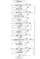
図2に示すように、制御部22は、衝突回避処理を開始すると、まずS10にて、レーダ装置4による検出結果に基づいて、前方物体があるか否かを判定する。制御部22は、S10にて、前方物体がないと判定した場合には、当該衝突回避処理を一旦終了する。
As shown in FIG. 2, when the collision avoidance process is started, the
また、制御部22は、S10にて、前方物体があると判定した場合には、S20に進み、前方物体と自車両とが衝突する可能性(以下、自車両衝突可能性)があるか否かを判定する。
If the
ここで、例えば図3に示すように、走行中の自車両MCの前方で自転車BCが自車両MCの左側から飛び出そうとしている状況を用いて、自車両衝突可能性があるか否かを判定する方法を説明する。 Here, for example, as shown in FIG. 3, it is determined whether there is a possibility of collision of the host vehicle using a situation where the bicycle BC is about to jump out of the left side of the host vehicle MC in front of the traveling host vehicle MC. How to do it.
まず、図4に示すように、自車両の前後方向をY軸とし、自車両の前後方向に対して垂直な方向をX軸とし、更に、自車両の前端中央部を原点Oとする二次元直交座標系を設定する。原点Oの座標は「(0,0)」とする。 First, as shown in FIG. 4, a two-dimensional model in which the front-rear direction of the host vehicle is the Y axis, the direction perpendicular to the front-rear direction of the host vehicle is the X axis, and the center of the front end of the host vehicle is the origin O. Set the Cartesian coordinate system. The coordinates of the origin O are “(0, 0)”.
自車両の全幅をWとし、自車両の全長をLとすると、座標が「(W/2,0)」である点P1と、座標が「(W/2,−L)」である点P2と、座標が「(−W/2,0)」である点P3と、座標が「(−W/2,−L)」である点P4とを頂点とする長方形RSが、自車両が存在している範囲となる。 If the total width of the host vehicle is W and the total length of the host vehicle is L, a point P1 whose coordinates are “(W / 2, 0)” and a point P2 whose coordinates are “(W / 2, −L)” And the vehicle has a rectangular RS whose vertex is a point P3 whose coordinates are “(−W / 2, 0)” and a point P4 whose coordinates are “(−W / 2, −L)”. It is the range that is.
そして、前回の衝突回避処理の実行時におけるレーダ装置4による検出結果と、今回の衝突回避処理の実行時におけるレーダ装置4による検出結果とに基づいて、自転車BCの右端部と左端部における相対速度ベクトルを算出する。尚、図4の例において、自転車BCの右端部は、自転車BCの前端部であり、自転車BCの左端部は、自転車BCの後端部である。例えば、前回の衝突回避処理の実行時における自転車BCの右端部と左端部の位置をそれぞれ点P11と点P12とする。また、今回の衝突回避処理の実行時における自転車BCの右端部と左端部の位置をそれぞれ点P13と点P14とする。この場合に、自転車BCの右端部における相対速度ベクトルV1は、点P13の座標値から点P11の座標値を減算することにより算出される。同様に、自転車BCの左端部における相対速度ベクトルV2は、点P14の座標値から点P12の座標値を減算することにより算出される。 And based on the detection result by the radar apparatus 4 at the time of execution of the previous collision avoidance process and the detection result by the radar apparatus 4 at the time of execution of the current collision avoidance process, the relative speed at the right end portion and the left end portion of the bicycle BC. Calculate the vector. In the example of FIG. 4, the right end portion of the bicycle BC is a front end portion of the bicycle BC, and the left end portion of the bicycle BC is a rear end portion of the bicycle BC. For example, the positions of the right end portion and the left end portion of the bicycle BC at the time of the previous collision avoidance process are set as a point P11 and a point P12, respectively. In addition, the positions of the right end and the left end of the bicycle BC at the time of execution of the current collision avoidance process are point P13 and point P14, respectively. In this case, the relative speed vector V1 at the right end of the bicycle BC is calculated by subtracting the coordinate value of the point P11 from the coordinate value of the point P13. Similarly, the relative speed vector V2 at the left end of the bicycle BC is calculated by subtracting the coordinate value of the point P12 from the coordinate value of the point P14.
そして、制御部22は、自転車BCの右端部の今回位置を示す点P13を起点とした相対速度ベクトルV1の延長線EL1に、自車両が存在している範囲を示す長方形RSが位置している場合に、自車両衝突可能性があると判断する。
And the
具体的には、まず、制御部22は、自転車BCの右端部を起点とした相対速度ベクトルV1の延長線EL1と、X軸との交点を算出する。
自転車BCの右端部(すなわち、点P13)の座標を「(x1,y1)」とし、相対速度ベクトルV1の傾きをaとすると、延長線EL1は下式(1)で表される。尚、「a=dy/dx」である。
Specifically, first, the
If the coordinate of the right end of the bicycle BC (that is, the point P13) is “(x1, y1)” and the inclination of the relative velocity vector V1 is a, the extension line EL1 is expressed by the following equation (1). Note that “a = dy / dx”.
y = a×(x−x1) + y1 …(1)
このため、下式(2)で示すように、式(1)において「y=0」としたときのxの値が、X軸との交点のx座標値である。
y = a × (x−x1) + y1 (1)
For this reason, as shown by the following equation (2), the value of x when “y = 0” in equation (1) is the x coordinate value of the intersection with the X axis.
0 = a×(x−x1) + y1 …(2)
そして、式(2)より、X軸との交点のx座標値は、下式(3)で表される。
x = −y1/a + x1 …(3)
このX座標値が、−W/2より大きく且つ+W/2より小さい範囲内である場合に、制御部22は、自車両衝突可能性があると判断する。そして、制御部22は、自転車BCの右端部(すなわち、点P13)と、自車両MC(すなわち、長方形RS)との交点との間の距離(以下、右端部衝突距離)d1を、下式(4)により算出する。
0 = a × (x−x1) + y1 (2)
From the equation (2), the x coordinate value of the intersection with the X axis is expressed by the following equation (3).
x = −y1 / a + x1 (3)
When the X coordinate value is in a range larger than −W / 2 and smaller than + W / 2, the
d1 = {y12 + (y1/a)2}−1/2
= (1+1/a2)−1/2×y1 …(4)
更に、制御部22は、自転車BCの右端部を起点とした相対速度ベクトルV1の延長線EL1と、長方形RSの左辺との交点を算出する。
d1 = {y1 2 + (y1 / a) 2 } −1/2
= (1 + 1 / a 2 ) −1 / 2 × y1 (4)
Further, the
下式(5)で示すように、式(1)において「x=−W/2」としたときのyの値が、長方形RSの左辺との交点のy座標値である。
y = a×(−W/2−x1) + y1 …(5)
このy座標値が、−Lより大きく且つ0より小さい範囲内である場合に、制御部22は、自車両衝突可能性があると判断する。そして、制御部22は、この場合の右端部衝突距離d1を、下式(6)により算出する。
As shown in the following equation (5), the value of y when “x = −W / 2” in equation (1) is the y coordinate value of the intersection with the left side of the rectangle RS.
y = a × (−W / 2−x1) + y1 (5)
When the y-coordinate value is in a range larger than −L and smaller than 0, the
d1=[(x1+w/2)2+{2×y1+a(w/2−x1)}2]−1/2 …(6)
次に、制御部22は、自転車BCの左端部を起点とした相対速度ベクトルV2の延長線EL2についても、延長線EL1と同様にして、X軸との交点と、長方形RSの左辺との交点とを算出することにより、車両衝突可能性を判断する。そして、制御部22は、車両衝突可能性があると判断した場合には、延長線EL1と同様にして、自転車BCの左端部(すなわち、点P14)と、自車両MCとの交点との間の距離d2(以下、左端部衝突距離d2)を算出する。尚、図4では、点P14の座標を「(x2,y2)」としている。
d1 = [(x1 + w / 2) 2 + {2 × y1 + a (w / 2−x1)} 2 ] −1/2 (6)
Next, similarly to the extension line EL1, the
また、制御部22は、自車両衝突可能性があると判断した場合には、図5に示すように、延長線EL1,EL2と長方形RSとが交差しないようにするためにX軸方向に沿って長方形RSを移動させる移動量(以下、横方向回避量)Xaを算出する。
Further, when the
そして、制御部22は、S20の処理が終了すると、図2に示すように、S30にて、S20での判定結果に基づいて、自車両衝突可能性があるか否かを判断する。制御部22は、S30にて、自車両衝突可能性がないと判定した場合には、当該衝突回避処理を一旦終了する。
Then, when the process of S20 ends, the
一方、制御部22は、S30にて、自車両衝突可能性があると判定した場合には、S40に進み、自車両と前方物体とが衝突するまでの時間の予測値である衝突予測時間TTCを算出する。尚、TTCは、「Time To Collision」の略である。
On the other hand, if the
ここで、例えば図3に示すように、走行中の自車両MCの前方で自転車BCが自車両MCの左側から飛び出そうとしている状況を用いて、衝突予測時間を算出する方法を説明する。 Here, for example, as shown in FIG. 3, a method of calculating the collision prediction time using a situation where the bicycle BC is about to jump out of the left side of the host vehicle MC in front of the traveling host vehicle MC will be described.
まず、制御部22は、図4に示すように、右端部衝突距離d1と、左端部衝突距離d2と、中央部衝突距離d3を算出する。尚、右端部衝突距離d1と左端部衝突距離d2は、S20の処理で既に算出されている。中央部衝突距離d3は、図4において点P15で示される自転車BCの中央部と、自車両MC(すなわち、長方形RS)との交点との間の距離である。制御部22は、S40では、右端部衝突距離d1および左端部衝突距離d2と同様の方法で中央部衝突距離d3を算出する。
First, as shown in FIG. 4, the
更に、制御部22は、自転車BCの速度VBを下式(7)で算出する。
VB = {(dx/dt)2+(dy/dt)2}−1/2 …(7)
そして、制御部22は、自転車BCの右端部の衝突予測時間TTC1と、自転車BCの左端部の衝突予測時間TTC2と、自転車BCの中央部の衝突予測時間TTC3を、それぞれ、下式(8),(9),(10)で算出する。
Further, the
V B = {(dx / dt) 2 + (dy / dt) 2 } −1/2 (7)
Then, the
TTC1 = d1/VB …(8)
TTC2 = d2/VB …(9)
TTC3 = d3/VB …(10)
そして、制御部22は、衝突予測時間TTC1,TTC2,TTC3の中で最も小さいものを、衝突予測時間TTCの算出結果として採用する。
TTC1 = d1 / V B (8)
TTC2 = d2 / V B (9)
TTC3 = d3 / V B (10)
And the
制御部22は、S40で衝突予測時間TTCの算出を終了すると、図2に示すように、S50に進む。
制御部22は、S50では、外気温が所定値TL以下か否かを判定する。具体的には、外気温センサ31によって検出された外気温を取得し、その外気温が所定値TL以下か否かを判定する。そして、制御部22は、S50では、外気温が所定値TL以下と判定した場合に、低摩擦状況であると判定する。低摩擦状況とは、自車両が走行している道路の路面摩擦係数が小さくなる状況のことである。尚、自動制動や自動操舵によって自車両の走行速度や進行方向を想定通りに変更可能な路面摩擦係数の最小値を、最小μとすると、所定値TLは、路面の積雪や凍結等により路面摩擦係数が最小μになると考えられる外気温と同じ値か、あるいは、その外気温よりも低い温度の値に設定されている。例えば、所定値TLは−7℃である。
When the calculation of the collision prediction time TTC is completed in S40, the
In S50, the
制御部22は、S50の処理が終了すると、S60にて、S50での判定結果に基づいて、外気温が所定値TL以下か否かを判定し、外気温が所定値TL以下であると判定した場合、すなわち低摩擦状況であると判定した場合には、S70に進む。そして、制御部22は、S70にて、後述する変更処理を行った後、S80に進む。尚、S70の変更処理は、自動制動と自動操舵との実施条件を、自動制動と自動操舵とが通常よりも早いタイミングで開始されるように変更するための処理である。また、制御部22は、S60にて、外気温が所定値TL以下でないと判定した場合、すなわち低摩擦状況でないと判定した場合には、S70をスキップしてS80に進む。
When the process of S50 ends, the
制御部22は、S80では、S40で算出した衝突予測時間TTCと、別の処理で取得している自車両の走行速度(以下、自車速)Vとに基づいて、回避動作の判定を行う。尚、制御部22は、例えばブレーキECU3から一定時間毎に自車速Vを取得している。
In S80, the
具体的には、図6に示すように、衝突予測時間TTCと自車速Vとの組み合わせは、第1領域R1と、第2領域R2と、第3領域R3と、第4領域R4とに分類される。尚、図6において、縦軸の「衝突予測時間」は、上にいくほど大きい値である。 Specifically, as shown in FIG. 6, the combinations of the predicted collision time TTC and the host vehicle speed V are classified into a first region R1, a second region R2, a third region R3, and a fourth region R4. Is done. In FIG. 6, the “collision prediction time” on the vertical axis is a value that increases as it goes upward.
第1領域R1と第2領域R2は、制動装置16により衝突を回避する領域である。尚、衝突を回避するとは、詳しくは、前方物体と自車両との衝突を回避することである。また、衝突を回避することを、衝突回避、あるいは単に、回避するともいう。
The first region R1 and the second region R2 are regions where the
第3領域R3は、衝突予測時間TTCと自車速Vとの組み合わせが、第2領域R2から当該第3領域R3に入った場合には、制動装置16と操舵装置12とにより衝突を回避する領域となる。また、第3領域R3は、衝突予測時間TTCと自車速Vとの組み合わせが、第1領域R1から当該第3領域R3に入った場合には、制動装置16により衝突を回避する領域となる。
The third region R3 is a region in which a collision is avoided by the
第4領域R4は、衝突回避装置1による回避支援を実行しない領域である。
そして、領域R1,R2,R3,R4は、制動回避限界時間T1、通常制動回避下限時間T2、操舵回避限界時間T3および通常操舵回避下限時間T4により決定される。
The fourth region R4 is a region where avoidance support by the
The regions R1, R2, R3, and R4 are determined by the braking avoidance limit time T1, the normal braking avoidance lower limit time T2, the steering avoidance limit time T3, and the normal steering avoidance lower limit time T4.
制動回避限界時間T1は、制動装置16を作動させることにより衝突を回避することができる最小の衝突予測時間であり、前方物体との相対速度に比例している。すなわち、衝突予測時間TTCが制動回避限界時間T1未満である状況下で運転者がブレーキ操作を開始した場合には、ブレーキ操作のみで衝突を回避することができない可能性が高い。
The braking avoidance limit time T1 is the minimum predicted collision time at which a collision can be avoided by operating the
通常制動回避下限時間T2は、衝突を回避するために自車両の運転者がブレーキ操作を開始する最小の衝突予測時間であり、前方物体との相対速度に比例している。
操舵回避限界時間T3は、ステアリング操作により衝突を回避することができる最小の衝突予測時間であり、前方物体との相対速度に依存しない一定値である。すなわち、衝突予測時間TTCが操舵回避限界時間T3未満である状況下で運転者がステアリング操作を開始した場合には、ステアリング操作のみで衝突を回避することができない可能性が高い。
The normal braking avoidance lower limit time T2 is the minimum collision prediction time for the driver of the host vehicle to start the brake operation in order to avoid the collision, and is proportional to the relative speed with the front object.
The steering avoidance limit time T3 is the minimum collision prediction time during which a collision can be avoided by a steering operation, and is a constant value that does not depend on the relative speed with the front object. That is, when the driver starts a steering operation under a situation where the predicted collision time TTC is less than the steering avoidance limit time T3, there is a high possibility that the collision cannot be avoided only by the steering operation.
通常操舵回避下限時間T4は、衝突を回避するために自車両の運転者がステアリング操作を開始する最小の衝突予測時間であり、前方物体との相対速度に依存しない一定値である。 The normal steering avoidance lower limit time T4 is the minimum predicted collision time when the driver of the host vehicle starts the steering operation in order to avoid a collision, and is a constant value that does not depend on the relative speed with the front object.
そして、第1領域R1は、通常制動回避下限時間T2未満であり、且つ、通常操舵回避下限時間T4未満であり、且つ、制動回避限界時間T1以上である領域である。
第2領域R2は、制動回避限界時間T1未満であり、且つ、通常操舵回避下限時間T4未満であり、且つ、操舵回避限界時間T3以上である領域である。
The first region R1 is a region that is less than the normal braking avoidance lower limit time T2, is less than the normal steering avoidance lower limit time T4, and is equal to or greater than the braking avoidance limit time T1.
The second region R2 is a region that is less than the braking avoidance limit time T1, is less than the normal steering avoidance lower limit time T4, and is equal to or longer than the steering avoidance limit time T3.
第3領域R3は、制動回避限界時間T1未満であり、且つ、操舵回避限界時間T3未満である領域である。
第4領域R4は、領域R1,R2,R3以外の領域である。
The third region R3 is a region that is less than the braking avoidance limit time T1 and less than the steering avoidance limit time T3.
The fourth region R4 is a region other than the regions R1, R2, and R3.
そして、例えばメモリ23には、図6に示すように、各時間T1〜T4と自車速Vとの関係を示すデータマップである標準領域マップが、各領域R1〜R4の情報として格納されている。
For example, as shown in FIG. 6, the
制御部22は、S80では、現時点における衝突予測時間TTCと自車速Vとの組み合わせ(以下、自車両状況)が、第1領域R1又は第2領域R2に含まれている場合に、制動により回避する状況であると判定する。
In S80, the
また、制御部22は、自車両状況が第3領域R3に含まれており、且つ、この第3領域R3へは第1領域R1から入った場合にも、制動により回避する状況であると判定する。
また、制御部22は、自車両状況が第3領域R3に含まれており、且つ、この第3領域R3へは第2領域R2から入った場合には、制動と操舵により回避する状況であると判定する。すなわち、この場合、制御部22は、制動により回避する状況であり、且つ、操舵により回避する状況であると判定する。
In addition, the
In addition, the
また、制御部22は、自車両状況が第4領域R4に含まれている場合に、回避動作を行わない状況であると判定する。このような判定が、回避動作の判定である。
制御部22は、S80の処理が終了すると、図2に示すように、S85にて、S80での判定結果に基づいて、操舵により回避する状況であるか否かを判断する。
In addition, the
When the process of S80 ends, the
制御部22は、S85にて、操舵により回避する状況でないと判定した場合には、そのままS110に移行するが、S85にて、操舵により回避する状況であると判定した場合には、S90に進む。
If it is determined in S85 that the situation is not to be avoided by steering, the
制御部22は、S90では、予め設定された操舵回避不適切条件が成立したか否かを判定する。この操舵回避不適切条件は、例えば、走行中の道路の前方において道路の周辺に住居が存在していること、走行中の道路の前方において道路と道路以外との間で高低差が大きいことである。このS90では、例えば、ナビゲーション装置5から取得した道路地図データを用いて、操舵回避不適切条件が成立したか否かを判断する。
In S90, the
制御部22は、S90にて、操舵回避不適切条件が成立していると判定した場合には、そのままS110に移行する。
また、制御部22は、S90にて、操舵回避不適切条件が成立していないと判定した場合には、S100に進む。
If the
If the
制御部22は、S100では、衝突回避のために操舵装置12により自車両の進行方向を変更させる自動操舵の制御(すなわち、自動操舵制御)として、衝突回避操舵制御を実施し、その後、S110に進む。S100の衝突回避操舵制御では、具体的には、操舵装置12を制御して自車両を衝突予測時間TTCで横方向に横方向回避量Xaだけ移動させる。また、操舵装置12の制御は、ステアリングECU2を介して実施されるが、操舵装置12は、衝突回避装置1からの制御信号によって直接的に制御されるように構成されていても良い。
In S100, the
制御部22は、S110では、S80での判定結果に基づいて、制動により回避する状況であるか否かを判断する。制御部22は、S110にて、制動により回避する状況でないと判定した場合には、当該衝突回避処理を一旦終了する。
In S110, the
また、制御部22は、S110にて、制動により回避する状況であると判定した場合には、S120に進む。
制御部22は、S120では、衝突回避のために制動装置16により自車両の走行速度を低減させる自動制動の制御(すなわち、自動制動制御)として、衝突回避制動制御を実施し、その後、当該衝突回避処理を一旦終了する。S120の衝突回避制動制御では、具体的には、制動装置16を制御して、予め設定された減速度で自車両を制動させる。制動装置16の制御は、ブレーキECU3を介して実施されるが、制動装置16は、衝突回避装置1からの制御信号によって直接的に制御されるように構成されていても良い。
If the
In S120, the
ここで、S70で実行される変更処理について説明する。
制御部22は、S70では、図7における矢印Y2で示すように、標準領域マップに記録されている通常制動回避下限時間T2を、自車速Vの全領域について、所定値だけ大きい値に補正する。更に、図7における矢印Y3で示すように、標準領域マップに記録されている操舵回避限界時間T3を、自車速Vの全領域について、所定値だけ大きい値に補正する。図7においては、一点鎖線が、増大補正された通常制動回避下限時間T2を示しており、二点鎖線が、増大補正された操舵回避限界時間T3を示している。そして、制御部22は、標準領域マップにおける通常制動回避下限時間T2及び操舵回避限界時間T3の各々を、増大補正した時間T2,T3に置き換えたデータマップを、補正領域マップとして作成する。尚、各時間T2,T3を大きくする値は、各時間T2,T3毎に異なっていても良いし、同じであっても良い。
Here, the changing process executed in S70 will be described.
In S70, the
そして、制御部22は、S60にて低摩擦状況であると判定した場合のS80では、S
70の変更処理で作成した補正領域マップを用いて、前述した回避動作の判定を行う。また、制御部22は、S60にて低摩擦状態でないと判定した場合のS80では、時間T2,T3を補正していない標準領域マップを用いて、前述した回避動作の判定を行う。
Then, the
The avoidance operation described above is determined using the correction area map created in the
このため、制御部22は、S60にて低摩擦状況であると判定した場合には、S60にて低摩擦状態でないと判定した場合である通常時と比較すると、衝突回避制動制御と衝突回避制動制御とを、衝突予測時間TCCが大きい時点で開始することとなる。
For this reason, when the
つまり、S60にて低摩擦状況であると判定された場合には、通常時と比較すると、通常制動回避下限時間T2が大きい値に変更されるため、衝突予測時間TTCは、大きい値の時点で、第1領域R1に含まれる。このため、制御部22は、衝突予測時間TCCが大きい時点で、制動により回避する状況であると判定して、衝突回避制動制御を行うこととなる。
In other words, when it is determined in S60 that the low friction state is present, the normal braking avoidance lower limit time T2 is changed to a larger value as compared with the normal time. , Included in the first region R1. Therefore, the
同様に、S60にて低摩擦状況であると判定された場合には、通常時と比較すると、操舵回避限界時間T3が大きい値に変更されるため、衝突予測時間TTCは、大きい値の時点で、第2領域R2から第3領域R3に遷移する。このため、制御部22は、衝突予測時間TCCが大きい時点で、操舵により回避する状況であると判定して、衝突回避操舵制御を行うこととなる。
Similarly, when it is determined in S60 that the friction state is low, the steering avoidance limit time T3 is changed to a larger value as compared with the normal time. Transition from the second region R2 to the third region R3. For this reason, the
よって、S60にて低摩擦状況であると判定された場合には、通常時と比較すると、衝突回避制動制御と衝突回避操舵制御との開始タイミングが早まる。
[1−3.効果]
第1実施形態の衝突回避装置1によれば、以下の効果を奏する。
Therefore, when it is determined in S60 that the state is a low friction state, the start timing of the collision avoidance braking control and the collision avoidance steering control is advanced compared to the normal time.
[1-3. effect]
The
(1a)制御部22は、S60にて低摩擦状況であると判定した場合には、S60にて低摩擦状態でないと判定した場合である通常時と比較すると、衝突回避制御としての衝突回避制動制御及び衝突回避操舵制御の開始タイミングを早める。
(1a) When the
このため、路面摩擦係数が前述の最小μよりも小さくなる状況において、衝突回避効果が低下してしまうことを抑制することができる。また仮に、衝突が回避できなかったとしても、衝突被害を軽減する効果が期待できる。 For this reason, in a situation where the road surface friction coefficient is smaller than the aforementioned minimum μ, it is possible to suppress the collision avoidance effect from being lowered. Even if a collision cannot be avoided, an effect of reducing the collision damage can be expected.
(1b)制御部22は、S70では、外気温が所定値TL以下か否かを判定し、外気温が所定値TL以下と判定した場合に、低摩擦状況であると判定する。このため、低摩擦状態か否かの判定を簡単に実施することができる。
(1b) In S70, the
(1c)制御部22は、所定値TL以下か否かを判定する判定対象の外気温として、自車両に備えられた外気温センサ31により検出された外気温を用いる。このため、外気温が所定値TL以下か否かの判定精度を向上させることができる。例えば、制御部22は、判定対象の外気温を、自車両外の地上の設備から無線通信等によって取得するように構成されても良いが、外気温センサ31による検出結果を判定対象とする方が、一層確かな判定結果を得ることができる。
(1c) The
(1d)制御部22は、一定時間毎に繰り返し算出する衝突予測時間TTCが、通常制動回避下限時間T2未満になった場合に、衝突回避制御の一つである衝突回避制動制御を実施する。また、制御部22は、衝突予測時間TTCが、操舵回避限界時間T3未満になった場合に、衝突回避制御の一つである衝突回避操舵制御を実施する。そして、制御部22は、60にて低摩擦状況であると判定した場合には、上記各時間T2,T3を大きい値に変更することにより、衝突回避制御の開始タイミングを早める。このため、衝突回避制
御の開始タイミングを早めるための処理が簡単になる。
(1d) The
変形例として、衝突回避制動制御の開始タイミングを早めるためには、通常操舵回避下限時間T4を大きい値に変更しても良いし、通常制動回避下限時間T2と通常操舵回避下限時間T4との両方を大きい値に変更しても良い。また、衝突回避制御としては、自動制動制御(衝突回避制動制御)と自動操舵制御(衝突回避操舵制御)との一方だけであっても良い。例えば、自動操舵制御を実施しない構成の場合、衝突回避処理においてS85〜S100は削除することができる。また例えば、自動制動制御を実施しない構成の場合、衝突回避処理においてS110,S120は削除することができる。また、自動制動制御と自動操舵制御との一方だけについて、開始タイミングを早めるように構成しても良い。 As a modified example, in order to advance the start timing of the collision avoidance braking control, the normal steering avoidance lower limit time T4 may be changed to a large value, or both the normal braking avoidance lower limit time T2 and the normal steering avoidance lower limit time T4. May be changed to a larger value. Further, the collision avoidance control may be only one of automatic braking control (collision avoidance braking control) and automatic steering control (collision avoidance steering control). For example, in the case where the automatic steering control is not performed, S85 to S100 can be deleted in the collision avoidance process. For example, in the case of a configuration in which automatic braking control is not performed, S110 and S120 can be deleted in the collision avoidance process. Further, the start timing may be advanced for only one of the automatic braking control and the automatic steering control.
尚、第1実施形態において、制御部22は、回避制御部、状況判定部及び変更部の各々として機能する。そして、S10〜S40,S80〜S120は、制御部22としての処理に相当し、S50は、状況判定部としての処理に相当し、S70は、変更部としての処理に相当する。また、制御部22としての処理のうち、S40は、算出部としての処理に相当する。また、S100の衝突回避操舵制御が自動操舵制御に相当し、S120の衝突回避制動制御が自動制動制御に相当する。また、通常制動回避下限時間T2と通常操舵回避下限時間T4との少なくとも一方は、自動制動制御の開始タイミングを決めることについての所定値に相当する。また、操舵回避限界時間T3は、自動操舵制御の開始タイミングを決めることについての所定値に相当する。
In the first embodiment, the
[2.第2実施形態]
[2−1.第1実施形態との相違点]
第2実施形態は、基本的な構成は第1実施形態と同様であるため、相違点について以下に説明する。尚、第1実施形態と同じ符号は、同一の構成を示すものであって、先行する説明を参照する。
[2. Second Embodiment]
[2-1. Difference from the first embodiment]
Since the basic configuration of the second embodiment is the same as that of the first embodiment, differences will be described below. Note that the same reference numerals as those in the first embodiment indicate the same configuration, and the preceding description is referred to.
第2実施形態の衝突回避装置1は、第1実施形態と比較すると、制御部22が、図2の衝突回避処理に代えて、図8の衝突回避処理を実行する点が異なる。
そして、図8の衝突回避処理は、図2の衝突回避処理と比較すると、S50,S60に代えて、S55,S55を備える点が異なる。
The
8 is different from the collision avoidance process in FIG. 2 in that S55 and S55 are provided instead of S50 and S60.
図8に示すように、制御部22は、S40で衝突予測時間TTCを算出した後、S55に進む。
制御部22は、S55では、自車両の現在位置において降雪があることを示す降雪情報(以下、自車位置降雪情報)を取得したか否かを判定する。そして、制御部22は、S55では、自車位置降雪情報を取得したと判定した場合に、低摩擦状況であると判定する。
As shown in FIG. 8, after calculating the collision prediction time TTC in S40, the
In S55, the
尚、自車位置降雪情報としては、例えば、自車両が存在する市、町、村等の所定の単位地域について降雪があることを示す降雪情報で良い。また、降雪情報は、地上の放送局等の情報提供施設から無線で送信されたものが、ナビゲーション装置5によって受信される。そして、制御部22は、その受信された降雪情報を、ナビゲーション装置5から通信線6を介して取得する。ナビゲーション装置5から衝突回避装置1へは、受信された降雪情報のうち、自車位置降雪情報だけが送信されても良いし、受信された全ての降雪情報が送信されても良い。
The own vehicle position snowfall information may be, for example, snowfall information indicating that there is snow in a predetermined unit area such as a city, town, village where the host vehicle exists. Also, the snowfall information received by the
制御部22は、S55の処理が終了すると、S65にて、S55での判定結果に基づいて、自車位置降雪情報を取得したか否かを判定し、自車位置降雪情報を取得したと判定した場合、すなわち、低摩擦状況であると判定した場合には、前述のS70に進む。また、制御部22は、S65にて、自車位置降雪情報を取得していないと判定した場合、すなわ
ち低摩擦状況でないと判定した場合には、S70をスキップしてS80に進む。
When the process of S55 ends, the
[2−2.効果]
第2実施形態の衝突回避装置1では、制御部22が、自車位置降雪情報を取得した場合に、低摩擦状況であると判定して、衝突回避制御としての衝突回避制動制御及び衝突回避操舵制御の開始タイミングを早める。このため、上記(1a)で述べた効果と同じ効果が得られる。更に、第1実施形態と同様に、低摩擦状態か否かの判定を簡単に実施することができる。また、上記(1d)で述べた効果も得られる。
[2-2. effect]
In the
尚、第2実施形態では、S55が、状況判定部としての処理に相当する。
[3.変形例]
以下に変形例を説明するが、この変形例も、基本的な構成は第1実施形態と同様であるため、相違点について以下に説明する。また、第1実施形態と同じ符号は、同一の構成を示すものであって、先行する説明を参照する。
In the second embodiment, S55 corresponds to processing as a situation determination unit.
[3. Modified example]
Although a modified example will be described below, the basic configuration of this modified example is the same as that of the first embodiment, and differences will be described below. The same reference numerals as those in the first embodiment indicate the same configuration, and the preceding description is referred to.
路面摩擦係数が小さい場合以外にも、例えば、制動装置16を動作させるアクチュエータ、すなわちブレーキアクチュエータ17の出力が制限されている状況では、自動制動によって自車速を想定通りに低減させることができない可能性がある。同様に、操舵装置12を動作させるアクチュエータ、すなわちステアリングアクチュエータ13の出力が制限されている状況では、自動操舵によって自車両の進行方向を想定通りに変更することができない可能性がある。このため、ステアリングアクチュエータ13又はブレーキアクチュエータ17の出力が制限されている状況においては、十分な衝突回避効果が得られない可能性がある。
In addition to the case where the road surface friction coefficient is small, for example, in the situation where the output of the actuator that operates the
そこで、変形例の衝突回避装置1は、第1実施形態と比較すると、制御部22が、図2の衝突回避処理に代えて、図9の衝突回避処理を実行する点が異なる。
そして、図9の衝突回避処理は、図2の衝突回避処理と比較すると、S50,S60に代えて、S57,S67を備える点が異なる。
Therefore, the
9 is different from the collision avoidance process in FIG. 2 in that S57 and S67 are provided instead of S50 and S60.
図9に示すように、制御部22は、S40で衝突予測時間TTCを算出した後、S57に進む。
制御部22は、S57では、ステアリングアクチュエータ13とブレーキアクチュエータ17との各々について、出力制限状態であるか否かを判定する。
As shown in FIG. 9, after calculating the collision prediction time TTC in S40, the
In S57, the
例えば、ステアリングECU2は、ステアリングアクチュエータ13の温度を監視しており、その温度が規定値以上になると、温度上昇を防止するために、アクチュエータ13の出力を制限する動作モード(以下、出力制限モード)に移行する。そして、ステアリングECU2は、出力制限モードになると、衝突回避装置1へ、過熱保護による出力制限情報を送信する。このため、制御部22は、ステアリングECU2から出力制限情報を取得した場合に、ステアリングアクチュエータ13が出力制限状態であると判定する。
For example, the
同様に、ブレーキECU3は、ブレーキアクチュエータ17の温度を監視しており、その温度が規定値以上になると、温度上昇を防止するために、アクチュエータ17の出力を制限する出力制限モードに移行する。そして、ブレーキECU3は、出力制限モードになると、衝突回避装置1へ、過熱保護による出力制限情報を送信する。このため、制御部22は、ブレーキECU3から出力制限情報を取得した場合に、ブレーキアクチュエータ17が出力制限状態であると判定する。
Similarly, the
また、アクチュエータ13,17の動力源は自車両のバッテリ電圧であるため、バッテリ電圧が所定値以下の場合にも、アクチュエータ13,17は100%の力を出力するこ
とができない。つまり、アクチュエータ13,17は出力制限状態となる。このため、制御部22は、バッテリ電圧が所定値以下であると判定した場合にも、アクチュエータ13,17が出力制限状態であると判定する。尚、制御部22は、出力制限情報に基づく判定と、バッテリ電圧に基づく判定との、一方だけを行うようになっていても良い。
Further, since the power source of the
制御部22は、S57の処理が終了すると、S67にて、S57での判定結果に基づいて、アクチュエータ13,17の何れかが出力制限状態であるか否かを判定する。
そして、アクチュエータ13,17が両方とも出力制限状態ではないと判定した場合には、S70をスキップして、S80に進むが、アクチュエータ13,17の何れかが出力制限状態であると判定した場合には、S70に進む。
When the process of S57 ends, the
When it is determined that both the
そして、制御部22は、S70では、前述の変更処理を実行することにより、衝突回避制動制御と衝突回避操舵制御の開始タイミングを早める。尚、制御部22は、アクチュエータ13,17のうち、ブレーキアクチュエータ17だけが出力制限状態であると判定した場合のS70では、例えば、前述の時間T2を大きい値に変更することにより、衝突回避制動制御の開始タイミングを早めても良い。また、制御部22は、アクチュエータ13,17のうち、ステアリングアクチュエータ13だけが出力制限状態であると判定した場合のS70では、例えば、前述の時間T3を大きい値に変更することにより、衝突回避操舵制御の開始タイミングを早めても良い。
And in S70, the
以上のような変形例の衝突回避装置1によっても、衝突回避効果が低下してしまうことを抑制することができる。また、上記(1d)で述べた効果も得られる。
[4.他の実施形態]
以上、本開示の実施形態について説明したが、本開示は上述の実施形態に限定されることなく、種々変形して実施することができる。
Also by the
[4. Other Embodiments]
As mentioned above, although embodiment of this indication was described, this indication is not limited to the above-mentioned embodiment, and can carry out various modifications.
例えば、前方物体を検出する検出部としては、レーダ装置4に限らず、ソナーやカメラ等の物体検出装置であっても良い。
また、上記実施形態における1つの構成要素が有する複数の機能を、複数の構成要素によって実現したり、1つの構成要素が有する1つの機能を、複数の構成要素によって実現したりしても良い。また、複数の構成要素が有する複数の機能を、1つの構成要素によって実現したり、複数の構成要素によって実現される1つの機能を、1つの構成要素によって実現したりしても良い。また、上記実施形態の構成の一部を省略しても良い。また、上記実施形態の構成の少なくとも一部を、他の上記実施形態の構成に対して付加又は置換しても良い。尚、特許請求の範囲に記載した文言から特定される技術思想に含まれるあらゆる態様が本開示の実施形態である。
For example, the detection unit for detecting the front object is not limited to the radar device 4 but may be an object detection device such as a sonar or a camera.
In addition, a plurality of functions of one constituent element in the above-described embodiment may be realized by a plurality of constituent elements, or one function of one constituent element may be realized by a plurality of constituent elements. Further, a plurality of functions possessed by a plurality of constituent elements may be realized by one constituent element, or a single function realized by a plurality of constituent elements may be realized by one constituent element. Moreover, you may abbreviate | omit a part of structure of the said embodiment. Further, at least a part of the configuration of the above embodiment may be added to or replaced with the configuration of the other embodiment. In addition, all the aspects included in the technical idea specified from the wording described in the claims are embodiments of the present disclosure.
また、上述した衝突回避装置の他、当該衝突回避装置を構成要素とするシステム、当該衝突回避装置としてコンピュータを機能させるためのプログラム、このプログラムを記録した半導体メモリ等の非遷移的実態的記録媒体、衝突回避方法など、種々の形態で本開示を実現することもできる。 In addition to the above-described collision avoidance device, a system including the collision avoidance device as a constituent element, a program for causing a computer to function as the collision avoidance device, and a non-transitory actual recording medium such as a semiconductor memory storing the program The present disclosure can also be realized in various forms such as a collision avoidance method.
1…衝突回避装置、12…操舵装置、16…制動装置、22…制御部
DESCRIPTION OF
Claims (3)
当該車両制御装置が搭載された車両である自車両の前方に存在する物体と前記自車両との衝突を回避するための衝突回避制御として、前記自車両の操舵装置(12)を制御して前記自車両の進行方向を変更させる自動操舵制御(S100)と、前記自車両の制動装置(16)を制御して前記自車両の走行速度を低減させる自動制動制御(S120)との、両方又は一方を実施する回避制御部(22,S10〜S40,S80〜S120)と、
前記衝突回避制御を実施するためのアクチュエータ(13,17)が、当該アクチュエータの出力が制限されている出力制限状態であるか否かを判定する判定部(22,S57)と、
前記判定部により前記出力制限状態であると判定された場合には、前記判定部により前記出力制限状態でないと判定された場合よりも、前記回避制御部が前記衝突回避制御を開始するタイミングを早める変更部(22,S70)と、を備え、
前記アクチュエータは、バッテリ電圧を動力源とするアクチュエータであり、
前記アクチュエータを駆動する装置は、前記アクチュエータの温度が規定値以上になると、前記アクチュエータの過熱保護のために、前記アクチュエータの出力を制限する動作モードである出力制限モードになるように構成され、
前記判定部は、
前記アクチュエータを駆動する前記装置が前記出力制限モードになっている場合に、前記アクチュエータが前記出力制限状態であると判定するように構成されている、
車両制御装置。 A vehicle control device (1) comprising:
As a collision avoidance control for avoiding a collision between an object existing in front of the own vehicle, which is a vehicle on which the vehicle control device is mounted, and the own vehicle, the steering device (12) of the own vehicle is controlled to Either or both of automatic steering control (S100) for changing the traveling direction of the host vehicle and automatic braking control (S120) for controlling the braking device (16) of the host vehicle to reduce the traveling speed of the host vehicle. An avoidance control unit (22, S10 to S40, S80 to S120) for carrying out
A determination unit (22, S57) for determining whether or not the actuator (13, 17) for performing the collision avoidance control is in an output restriction state in which the output of the actuator is restricted;
When the determination unit determines that the output restriction state is set, the avoidance control unit starts the collision avoidance control earlier than when the determination unit determines that the output restriction state is not set. A change unit (22, S70) ,
The actuator is an actuator using a battery voltage as a power source,
The device for driving the actuator is configured to be in an output limiting mode, which is an operation mode for limiting the output of the actuator, in order to protect the actuator from overheating when the temperature of the actuator exceeds a specified value.
The determination unit
The actuator is configured to determine that the actuator is in the output restriction state when the device that drives the actuator is in the output restriction mode.
Vehicle control device.
前記判定部は、
前記アクチュエータの動力源である前記バッテリ電圧が所定値以下である場合にも、前記アクチュエータが前記出力制限状態であると判定するように構成されている、
車両制御装置。 The vehicle control device according to claim 1 ,
The determination unit
If the battery voltage is a power source of the actuator is less than a predetermined value is also the actuator is configured to determine that the said output limiting state,
Vehicle control device.
前記回避制御部は、
前記自車両と前記物体とが衝突するまでの時間の予測値である衝突予測時間を繰り返し算出する算出部(S40)を備え、前記算出部により算出された衝突予測時間が所定値未満になった場合に、前記衝突回避制御を実施するように構成されており、
前記変更部は、
前記判定部により前記出力制限状態であると判定された場合には、前記判定部により前記出力制限状態でないと判定された場合よりも、前記所定値を大きい値に変更することにより、前記回避制御部が前記衝突回避制御を開始するタイミングを早めるように構成されている、
車両制御装置。 The vehicle control device according to claim 1 or 2 ,
The avoidance control unit includes:
A calculation unit (S40) that repeatedly calculates a collision prediction time that is a predicted value of a time until the host vehicle and the object collide, and the collision prediction time calculated by the calculation unit is less than a predetermined value. And is configured to implement the collision avoidance control,
The changing unit is
When the determination unit determines that the output limit state is set, the avoidance control is performed by changing the predetermined value to a larger value than when the determination unit determines that the output limit state is not set. Configured to advance the timing at which the unit starts the collision avoidance control,
Vehicle control device.
Priority Applications (5)
| Application Number | Priority Date | Filing Date | Title |
|---|---|---|---|
| JP2016163907A JP6601345B2 (en) | 2016-08-24 | 2016-08-24 | Vehicle control device |
| CN201780051362.5A CN109641590B (en) | 2016-08-24 | 2017-08-24 | Vehicle control device |
| PCT/JP2017/030347 WO2018038211A1 (en) | 2016-08-24 | 2017-08-24 | Vehicle control device |
| US16/327,097 US20190210597A1 (en) | 2016-08-24 | 2017-08-24 | Vehicle control apparatus |
| DE112017004235.6T DE112017004235T5 (en) | 2016-08-24 | 2017-08-24 | Vehicle control device |
Applications Claiming Priority (1)
| Application Number | Priority Date | Filing Date | Title |
|---|---|---|---|
| JP2016163907A JP6601345B2 (en) | 2016-08-24 | 2016-08-24 | Vehicle control device |
Publications (3)
| Publication Number | Publication Date |
|---|---|
| JP2018032215A JP2018032215A (en) | 2018-03-01 |
| JP2018032215A5 JP2018032215A5 (en) | 2018-07-26 |
| JP6601345B2 true JP6601345B2 (en) | 2019-11-06 |
Family
ID=61245044
Family Applications (1)
| Application Number | Title | Priority Date | Filing Date |
|---|---|---|---|
| JP2016163907A Active JP6601345B2 (en) | 2016-08-24 | 2016-08-24 | Vehicle control device |
Country Status (5)
| Country | Link |
|---|---|
| US (1) | US20190210597A1 (en) |
| JP (1) | JP6601345B2 (en) |
| CN (1) | CN109641590B (en) |
| DE (1) | DE112017004235T5 (en) |
| WO (1) | WO2018038211A1 (en) |
Families Citing this family (10)
| Publication number | Priority date | Publication date | Assignee | Title |
|---|---|---|---|---|
| JP6460033B2 (en) * | 2016-04-11 | 2019-01-30 | 株式会社デンソー | Vehicle control device |
| US10773725B1 (en) * | 2017-08-25 | 2020-09-15 | Apple Inc. | Tire-road friction estimation and mapping |
| EP3752399A1 (en) * | 2018-02-15 | 2020-12-23 | Toyota Motor Europe | Control method for a vehicle, computer program, non-transitory computer-readable medium, and automated driving system |
| CN108859956A (en) * | 2018-07-15 | 2018-11-23 | 合肥市智信汽车科技有限公司 | A kind of vehicle bumper systems and method |
| FR3088275B1 (en) * | 2018-11-13 | 2021-06-18 | Renault Sas | OBSTACLE AVOIDANCE PROCESS AND SYSTEM INCLUDING THE CONTROL OF THE STEERING AND DIFFERENTIAL BRAKING SYSTEMS |
| CN109878513A (en) * | 2019-03-13 | 2019-06-14 | 百度在线网络技术(北京)有限公司 | Defensive driving strategy generation method, device, equipment and storage medium |
| WO2021054211A1 (en) * | 2019-09-19 | 2021-03-25 | 株式会社Jvcケンウッド | Driving assistance device, driving assistance method, and program |
| JP7348882B2 (en) * | 2020-07-15 | 2023-09-21 | トヨタ自動車株式会社 | Driving support devices, driving support methods and programs |
| JP7488165B2 (en) * | 2020-09-23 | 2024-05-21 | 株式会社アドヴィックス | Vehicle turning control device and vehicle turning control program |
| JP2022113287A (en) * | 2021-01-25 | 2022-08-04 | トヨタ自動車株式会社 | Vehicle collision avoidance support apparatus |
Family Cites Families (14)
| Publication number | Priority date | Publication date | Assignee | Title |
|---|---|---|---|---|
| JPS558319A (en) | 1978-06-30 | 1980-01-21 | Kubota Ltd | Centrifugal casting method |
| JPH02237836A (en) * | 1989-03-13 | 1990-09-20 | Nec Corp | On-vehicle alarm device for automobile |
| JP4747460B2 (en) * | 2001-06-06 | 2011-08-17 | 日産自動車株式会社 | Brake control device for vehicle |
| JP4790521B2 (en) * | 2005-08-24 | 2011-10-12 | 日野自動車株式会社 | Automatic braking control device |
| JP4918815B2 (en) * | 2006-06-23 | 2012-04-18 | トヨタ自動車株式会社 | Collision avoidance system |
| JP2009096349A (en) * | 2007-10-17 | 2009-05-07 | Mazda Motor Corp | Vehicle driving support device |
| JP2010163058A (en) * | 2009-01-16 | 2010-07-29 | Fujitsu Ten Ltd | Vehicular driving assistance device |
| DE102013204893A1 (en) * | 2013-03-20 | 2014-09-25 | Robert Bosch Gmbh | Method and system for avoiding a collision in connection with vehicles |
| US9561795B2 (en) * | 2014-05-16 | 2017-02-07 | Hyundai Motor Company | Vehicle collision avoidance apparatus and method |
| JP2015223926A (en) * | 2014-05-28 | 2015-12-14 | アイシン・エィ・ダブリュ株式会社 | Vehicle control system, method and program |
| US9925980B2 (en) * | 2014-09-17 | 2018-03-27 | Magna Electronics Inc. | Vehicle collision avoidance system with enhanced pedestrian avoidance |
| JP6528656B2 (en) | 2014-12-03 | 2019-06-12 | 日本製鉄株式会社 | Analysis method for hot stamp forming process, determination method, analysis apparatus and program |
| JP6485057B2 (en) * | 2015-01-19 | 2019-03-20 | アイシン精機株式会社 | Driving assistance device |
| CN105599763B (en) * | 2016-01-22 | 2019-01-25 | 奇瑞汽车股份有限公司 | A kind of control method for vehicle and device |
-
2016
- 2016-08-24 JP JP2016163907A patent/JP6601345B2/en active Active
-
2017
- 2017-08-24 DE DE112017004235.6T patent/DE112017004235T5/en active Pending
- 2017-08-24 CN CN201780051362.5A patent/CN109641590B/en active Active
- 2017-08-24 WO PCT/JP2017/030347 patent/WO2018038211A1/en active Application Filing
- 2017-08-24 US US16/327,097 patent/US20190210597A1/en not_active Abandoned
Also Published As
| Publication number | Publication date |
|---|---|
| DE112017004235T5 (en) | 2019-05-09 |
| US20190210597A1 (en) | 2019-07-11 |
| JP2018032215A (en) | 2018-03-01 |
| CN109641590B (en) | 2022-08-02 |
| WO2018038211A1 (en) | 2018-03-01 |
| CN109641590A (en) | 2019-04-16 |
Similar Documents
| Publication | Publication Date | Title |
|---|---|---|
| JP6601345B2 (en) | Vehicle control device | |
| CN105292114B (en) | Collision avoidance apparatus | |
| JP6523361B2 (en) | Vehicle control system, vehicle control method, and vehicle control program | |
| EP3339124B1 (en) | Autonomous driving system | |
| JP6657881B2 (en) | Vehicle control device | |
| JP6152673B2 (en) | Lane change support device | |
| JP6515823B2 (en) | Lane change support device | |
| JP6451857B2 (en) | Method for controlling travel control device and travel control device | |
| KR101470155B1 (en) | Apparatus and method for alarming impact | |
| JP6666883B2 (en) | Driving support device | |
| JP7112658B2 (en) | Vehicle driving support system and method | |
| CN111824137B (en) | Motor vehicle and method for avoiding collision | |
| JP2019151185A (en) | Driving support device | |
| JP6436235B2 (en) | Tracking control device and tracking control method | |
| JP7156924B2 (en) | Lane boundary setting device, lane boundary setting method | |
| JP6614353B2 (en) | Travel control method and travel control apparatus | |
| JP2016007954A (en) | Lane merging assist system | |
| JP6973978B2 (en) | Control device and control method to control the behavior of the motorcycle during lane splitting | |
| JP2020001668A (en) | Vehicular travel control system | |
| US20210061356A1 (en) | Vehicle control device | |
| JP2020111302A (en) | Vehicle driving support system and method | |
| JP2020069969A (en) | Vehicle control system | |
| US20230084217A1 (en) | Vehicle Control Method and Vehicle Control Device | |
| JP7198005B2 (en) | Vehicle position detector | |
| JP7200712B2 (en) | VEHICLE MOTION CONTROL METHOD AND VEHICLE MOTION CONTROL DEVICE |
Legal Events
| Date | Code | Title | Description |
|---|---|---|---|
| A521 | Request for written amendment filed |
Free format text: JAPANESE INTERMEDIATE CODE: A523 Effective date: 20180615 |
|
| A621 | Written request for application examination |
Free format text: JAPANESE INTERMEDIATE CODE: A621 Effective date: 20180621 |
|
| A131 | Notification of reasons for refusal |
Free format text: JAPANESE INTERMEDIATE CODE: A131 Effective date: 20190521 |
|
| A521 | Request for written amendment filed |
Free format text: JAPANESE INTERMEDIATE CODE: A523 Effective date: 20190626 |
|
| TRDD | Decision of grant or rejection written | ||
| A01 | Written decision to grant a patent or to grant a registration (utility model) |
Free format text: JAPANESE INTERMEDIATE CODE: A01 Effective date: 20190910 |
|
| A61 | First payment of annual fees (during grant procedure) |
Free format text: JAPANESE INTERMEDIATE CODE: A61 Effective date: 20190923 |
|
| R151 | Written notification of patent or utility model registration |
Ref document number: 6601345 Country of ref document: JP Free format text: JAPANESE INTERMEDIATE CODE: R151 |
|
| R250 | Receipt of annual fees |
Free format text: JAPANESE INTERMEDIATE CODE: R250 |
|
| R250 | Receipt of annual fees |
Free format text: JAPANESE INTERMEDIATE CODE: R250 |