JP6599819B2 - Packet relay device - Google Patents
Packet relay device Download PDFInfo
- Publication number
- JP6599819B2 JP6599819B2 JP2016111112A JP2016111112A JP6599819B2 JP 6599819 B2 JP6599819 B2 JP 6599819B2 JP 2016111112 A JP2016111112 A JP 2016111112A JP 2016111112 A JP2016111112 A JP 2016111112A JP 6599819 B2 JP6599819 B2 JP 6599819B2
- Authority
- JP
- Japan
- Prior art keywords
- packet
- attack
- mirror
- information
- relay device
- Prior art date
- Legal status (The legal status is an assumption and is not a legal conclusion. Google has not performed a legal analysis and makes no representation as to the accuracy of the status listed.)
- Active
Links
Images


Classifications
-
- H—ELECTRICITY
- H04—ELECTRIC COMMUNICATION TECHNIQUE
- H04L—TRANSMISSION OF DIGITAL INFORMATION, e.g. TELEGRAPHIC COMMUNICATION
- H04L63/00—Network architectures or network communication protocols for network security
- H04L63/14—Network architectures or network communication protocols for network security for detecting or protecting against malicious traffic
- H04L63/1408—Network architectures or network communication protocols for network security for detecting or protecting against malicious traffic by monitoring network traffic
- H04L63/1416—Event detection, e.g. attack signature detection
-
- H—ELECTRICITY
- H04—ELECTRIC COMMUNICATION TECHNIQUE
- H04L—TRANSMISSION OF DIGITAL INFORMATION, e.g. TELEGRAPHIC COMMUNICATION
- H04L12/00—Data switching networks
- H04L12/28—Data switching networks characterised by path configuration, e.g. LAN [Local Area Networks] or WAN [Wide Area Networks]
- H04L12/46—Interconnection of networks
- H04L12/4641—Virtual LANs, VLANs, e.g. virtual private networks [VPN]
- H04L12/4645—Details on frame tagging
- H04L12/4666—Operational details on the addition or the stripping of a tag in a frame, e.g. at a provider edge node
-
- H—ELECTRICITY
- H04—ELECTRIC COMMUNICATION TECHNIQUE
- H04L—TRANSMISSION OF DIGITAL INFORMATION, e.g. TELEGRAPHIC COMMUNICATION
- H04L49/00—Packet switching elements
- H04L49/20—Support for services
- H04L49/208—Port mirroring
-
- H—ELECTRICITY
- H04—ELECTRIC COMMUNICATION TECHNIQUE
- H04L—TRANSMISSION OF DIGITAL INFORMATION, e.g. TELEGRAPHIC COMMUNICATION
- H04L63/00—Network architectures or network communication protocols for network security
- H04L63/02—Network architectures or network communication protocols for network security for separating internal from external traffic, e.g. firewalls
- H04L63/0227—Filtering policies
- H04L63/0236—Filtering by address, protocol, port number or service, e.g. IP-address or URL
Landscapes
- Engineering & Computer Science (AREA)
- Computer Networks & Wireless Communication (AREA)
- Signal Processing (AREA)
- Computer Security & Cryptography (AREA)
- Computer Hardware Design (AREA)
- Computing Systems (AREA)
- General Engineering & Computer Science (AREA)
- Data Exchanges In Wide-Area Networks (AREA)
Description
本発明は、ネットワークにおいてパケットをミラーするパケット中継装置に関する。 The present invention relates to a packet relay device that mirrors a packet in a network.
DDoS(Distributed Denial of Service)攻撃や、標的型攻撃等によるセキュリティリスクが高まっている。攻撃の被害を最小化するには、攻撃対象より上流に位置するネットワークで攻撃を仕掛ける攻撃パケットを監視して、攻撃を検知した場合にはこれを防御することが必要である。 Security risks due to DDoS (Distributed Denial of Service) attacks and targeted attacks are increasing. In order to minimize the damage of the attack, it is necessary to monitor the attack packets that are attacked in the network located upstream from the attack target, and to defend against this if an attack is detected.
また、大規模攻撃の予兆を分析して対策を備えるにも、ネットワークで攻撃の予兆を有する攻撃予兆パケットを監視してこれを分析することが必要である。そのため、ネットワークを構成するルータやスイッチ等のパケット中継装置で、パケット中継装置が備えるミラー機能を用いて、パケット中継装置内のパケットを攻撃の分析機能を備えるアナライザに送信することでトラフィックデータを収集する。 Also, in order to analyze a sign of a large-scale attack and prepare a countermeasure, it is necessary to monitor and analyze a sign of an attack sign that has a sign of an attack on the network. For this reason, traffic data is collected by sending packets in the packet relay device to an analyzer that has an attack analysis function using the mirror function provided in the packet relay device in packet relay devices such as routers and switches that make up the network. To do.
そして、収集したトラフィックデータをアナライザで分析した結果、攻撃、または攻撃予兆の発生を検知した場合には、分析結果に基づいて攻撃を防御する対策を実施する。ネットワークを利用した攻撃には後述するように、システムの脆弱性を利用したLogic攻撃や、送信元を詐称した攻撃、大量のパケットを送りつけてネットワークの帯域資源や、サーバの処理資源等を枯渇させるフラッド攻撃、標的への侵入を試みる攻撃予兆等、多種多様な攻撃種別が存在する。 Then, as a result of analyzing the collected traffic data with an analyzer, when an occurrence of an attack or a sign of an attack is detected, measures are taken to prevent the attack based on the analysis result. As described later, attacks using the network are logic attacks that use system vulnerabilities, attacks that spoof senders, send a large number of packets to exhaust network bandwidth resources, server processing resources, etc. There are a wide variety of attack types, such as flood attacks to be made and attack signs that attempt to penetrate the target.
攻撃の種別毎に、分析に必要な情報、分析方法、分析の困難さ等が異なるため、攻撃種別に応じてFW(Firewall)、IDS(Intrusion Detection System)、IPS(Intrusion Protection System)、WAF(Web Application Firewall)、DDoS攻撃対策装置、フォレンジックサーバ等の多種多様なアナライザが提供されている。 Information required for analysis, analysis method, difficulty of analysis, etc. differ depending on the type of attack, so FW (Firewall), IDS (Intrusion Detection System), IPS (Intrusion Protection System), WAF ( Various analyzers such as Web Application Firewall), DDoS attack countermeasure devices, and forensic servers are provided.
攻撃の分析を行う際、アナライザの分析性能がネックとなり、パケット中継装置が中継する全てのトラフィックの分析を行うことはできない。そのため、非特許文献1では、詳細について分析したいトラフィックの識別条件をスイッチに設定し、特定のトラフィックのみをアナライザの一種であるIDSに転送する技術が開示されている。
When analyzing an attack, the analysis performance of the analyzer becomes a bottleneck, and it is not possible to analyze all the traffic relayed by the packet relay device. Therefore,
多種多様な攻撃種別を分析するには、対応する攻撃種別の異なる複数のアナライザをパケット中継装置に接続し、パケット中継装置による一次スクリーニングで攻撃種別をある程度絞り、スクリーニング後のパケットを攻撃種別に対応するアナライザに振り分ける必要がある。攻撃種別毎に分析方法が異なるので、スクリーニング方法も攻撃種別毎に異なる。 To analyze a wide variety of attack types, connect multiple analyzers with different corresponding attack types to the packet relay device, narrow down the attack types to some extent by primary screening by the packet relay device, and handle the screened packets for the attack type It is necessary to distribute it to the analyzers. Since the analysis method is different for each attack type, the screening method is also different for each attack type.
非特許文献1に開示される技術では、AFM(Aggregated Flow Mining)という単一種別のスクリーニング方法でトラフィックを絞り込み、IDSという単一種別のアナライザに転送する方法しか開示されていない。また、非特許文献2に開示される技術には、ポートスキャンの検出に関する技術は開示されている。
In the technique disclosed in
これらの従来の技術では、パケットに含まれる脅威を複数の攻撃種別に絞り、攻撃種別に適したアナライザに転送することはできない、という問題があった。すなわち、上記従来の技術では、アナライザに全てのパケットを入力されるので、アナライザでは複数の攻撃種別に対応するために負荷が過大になる場合があった。 These conventional techniques have a problem that the threats included in the packet cannot be narrowed down to a plurality of attack types and transferred to an analyzer suitable for the attack type. That is, in the above conventional technique, since all packets are input to the analyzer, the analyzer may have an excessive load in order to cope with a plurality of attack types.
本発明は、受信または送信されるパケットをコピーしたミラーパケットをミラーポートから送信するパケット中継装置であって、入力ポートからパケットを受け付けるパケット受付部と、前記パケットが攻撃または攻撃予兆の可能性を含むか否かを判定するセキュリティ判定部と、前記パケットが攻撃または攻撃予兆の可能性を含むと判定された場合に、当該パケットの複製を前記ミラーパケットとして生成するミラー処理部と、前記ミラーパケットをミラーポートから送信する送信部と、を有し、前記セキュリティ判定部は、前記攻撃または攻撃予兆に関する情報として、攻撃種別または攻撃予兆種別の情報を判定し、前記ミラー処理部は、前記セキュリティ判定部で判定された前記攻撃種別または攻撃予兆種別の情報に基づいてミラーパケットを生成し、前記送信部は、前記ミラーパケットにポリシングを行うミラーポリシング部と、前記ミラーポリシング部からの前記ミラーパケットに対してシェーピングを行うミラーシェーピング部と、ミラーシェーピング部とからの前記ミラーパケットに対してサンプリングを行うミラーサンプリング部と、を含む。 The present invention relates to a packet relay apparatus that transmits a mirror packet obtained by copying a packet to be received or transmitted from a mirror port, a packet reception unit that receives a packet from an input port, and a possibility that the packet is an attack or a sign of an attack. A security determination unit that determines whether or not to include a mirror processing unit that generates a copy of the packet as the mirror packet when it is determined that the packet includes an attack or a possibility of an attack sign, and the mirror packet the have a, a transmission unit for transmitting from the mirror port, said security judging unit, as the information on the attack or attack sign determines information attack type or attack sign type, the mirror unit, the security determination Based on the information of the attack type or attack predictor type determined by the The transmission unit generates a mirror, a mirror policing unit for policing the mirror packet, a mirror shaping unit for shaping the mirror packet from the mirror policing unit, and a mirror shaping unit A mirror sampling unit for sampling the mirror packet.
本発明によれば、パケット中継装置は攻撃または攻撃予兆の可能性があると判定されたパケットだけをミラーポートに出力することができるので、ミラーポートに接続された装置(例えば、アナライザ)の負荷を軽減することができる。 According to the present invention, since the packet relay apparatus can output only the packet determined to be an attack or a sign of an attack to the mirror port, the load on the apparatus (for example, analyzer) connected to the mirror port Can be reduced.
以下、本発明の実施形態を添付図面に基づいて説明する。 Hereinafter, embodiments of the present invention will be described with reference to the accompanying drawings.
図1は、本発明の第1の実施例を示し、中継装置を用いたネットワークのブロック図である。 FIG. 1 is a block diagram of a network using a relay device according to a first embodiment of the present invention.
図1において、本発明のパケット中継装置100でインターネット400から受信した受信パケット、またはインターネット400へ送信する送信パケットをアナライザ300−1〜300−nにミラーするネットワークの構成図を示す。
FIG. 1 shows a network configuration diagram in which analyzers 300-1 to 300-n mirror received packets received from the Internet 400 or transmitted packets sent to the Internet 400 by the
アナライザ300−1〜300−nは例えば、FW、IDS、IPS、WAF、DDoS攻撃対策装置、フォレンジックサーバ等のセキュリティ装置である。以下、アナライザ300−1〜300−nの全体を示すときには「−」以降の添え字のない符号300を用いる。他の構成要素の符号についても同様である。また、受信パケットと送信パケットの総称をパケットとする。
The analyzers 300-1 to 300-n are security devices such as FW, IDS, IPS, WAF, DDoS attack countermeasure device, and forensic server. Hereinafter, when the analyzers 300-1 to 300-n are shown as a whole, a
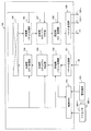
図2に本発明のパケット中継装置100のブロック図を示す。本発明のパケット中継装置100は、入力回線を接続する入力ポート130と、パケットを受信するパケット受信部101と、受信パケットを出力する出力ポートの判定と受信パケットの優先度の判定を含む基本的なパケット中継に関する判定処理とアナライザ300から送信されたパケット中継装置100宛の設定指示に関するパケットの制御CPU120への転送を行う受信側パケット処理部102と、受信パケットの攻撃または攻撃予兆に関する判定を行う受信側セキュリティ判定部103と、受信パケットのミラーに関する判定と受信ミラーパケットを生成するコピー処理を行う受信側ミラー処理部104と、受信側で判定した出力ポートに基づいて受信パケットを送信側に中継するパケット中継処理部105と、送信側における送信パケットの優先度の判定を含む基本的なパケット中継に関する判定処理を行う送信側パケット処理部106と、送信パケットの攻撃または攻撃予兆に関する判定を行う送信側セキュリティ判定部107と、送信パケットのミラーに関する判定と送信ミラーパケットを生成するコピー処理を行う送信側ミラー処理部108と、送信パケットの送信を行うパケット送信部109と、出力回線を接続する出力ポート131と、ミラー回線を接続するミラーポート132−1〜132−nと、管理端末121の指示またはアナライザ300から送信されたパケット中継装置100宛の設定指示に関するパケットの指示に基づいてパケット中継装置100が備える各種テーブルの設定指示を行う制御CPU120と、パケット中継装置100の管理者がパケット中継装置100に対する設定を入力する管理端末121から構成される。
FIG. 2 shows a block diagram of the
受信側セキュリティ判定部103の判定結果に基づいて受信側ミラー処理部104で受信ミラーに関する判定を行い、当該判定に基づいて受信ミラーパケットを生成する構成と、送信側セキュリティ判定部107の判定結果に基づいて送信側ミラー処理部108で送信ミラーに関する判定を行い判定に基づいて送信ミラーパケットを生成する構成と、受信ミラーパケットに受信側セキュリティ判定部103の判定結果の情報を付加してミラーする構成と、送信ミラーパケットに送信側セキュリティ判定部107の判定結果の情報を付加してミラーする構成が、本発明に特徴的な構成である。
Based on the determination result of the reception-side
また、本発明のパケット中継装置100の判定結果の情報を付加してミラーする機能に連携して動作するアナライザ300は、本発明のパケット中継装置100が送信したミラーパケットにおいて本発明のパケット中継装置100が判定結果の情報を付加したか否かに対応する動作モードを備える。
The
パケット中継装置100の判定結果の情報を付加しない場合に対応するアナライザ300の動作モードでは、通常のアナライザ300としてミラーパケットを分析する。一方、パケット中継装置100の判定結果の情報を付加する場合に対応する動作モードでは、判定結果の情報が含まれる位置と情報の意味をアナライザ300の管理者が設定可能とし、ミラーパケットをアナライザ300が受信すると、アナライザ300は判定結果の情報をミラーパケットから抽出し、抽出後は通常のアナライザとしてミラーパケットを分析する構成とする。
In the operation mode of the
ただし、アナライザ300の分析において抽出した判定結果の情報で判定可能な判定処理はスキップすることにより、アナライザ300の分析の負荷を低減できる。例えばパケット中継装置100が受信したパケットをフラッド攻撃であると判定し、この判定結果をミラーパケットに付加した場合は、アナライザ300では当該パケットがフラッド攻撃であるか否かを判定する処理をスキップし、フラッド攻撃を構成するパケットに対する分析の処理から始めることができる。
However, it is possible to reduce the analysis load of the
なお、アナライザ300及び管理端末121と制御CPU120は、図示しない管理用のネットワークを介して接続するようにしてもよい。
The
図3は、受信側パケット処理部102が出力するパケット情報200の一例を示す図である。
FIG. 3 is a diagram illustrating an example of the
受信パケットのL2(Layer2)情報211と、L3(Layer3)情報212と、L4(Layer4)情報213と、L7(Layer7)情報214と、ペイロード215に対し、パケット受信部101で入力ポート情報201を付加し、受信側パケット処理部102で判定した出力ポート情報202と優先度情報203を付加した図3に示すパケット情報200を、受信側パケット処理部102から受信側セキュリティ判定部103に出力する。
For the L2 (Layer 2)
図4は、受信側セキュリティ判定部103の構成の一例を示すブロック図である。受信側セキュリティ判定部103は、攻撃種別または攻撃予兆の種別を判定する攻撃種別判定部1031と、攻撃種別または攻撃予兆種別の判定結果に基づいて攻撃の影響度を判定する攻撃影響度判定部1032と、攻撃種別または攻撃予兆種別の判定結果に基づいて攻撃の確からしさを判定する攻撃確度判定部1033から構成される。
FIG. 4 is a block diagram illustrating an example of the configuration of the reception-side
送信側セキュリティ判定部107も、受信側セキュリティ判定部103と同様の構成である(ただし、後述する「(3)送信元詐称攻撃」に関する処理は、送信側では後述する経路テーブル1020を備えないので実施しない)。
The transmission-side
図5は、受信側セキュリティ判定部103が出力するパケット情報250の一例を示す図である。受信側セキュリティ判定部103では、受信側パケット処理部102から入力したパケット情報200に対し、受信側セキュリティ判定部103で判定した攻撃種別情報221と、攻撃影響度情報222と、攻撃確度情報223と、攻撃経路情報224を付加した図5に示すパケット情報250を、受信側ミラー処理部104に出力する。送信側セキュリティ判定部107も、受信側セキュリティ判定部103と同様の処理を行う。
FIG. 5 is a diagram illustrating an example of the
図6は受信側ミラー処理部104の構成の一例を示すブロック図である。受信側ミラー処理部104は、攻撃種別情報221、攻撃影響度情報222、攻撃確度情報223、攻撃経路情報224に基づいて受信ミラーパケットの生成可否と、ミラーパケットを生成する場合にはミラーパケットを送信するミラーポート132と、ミラーポート132においてミラーパケットを送信する優先度であるミラー優先度を判定するミラーポート判定部1041と、当該ミラーポート132において攻撃種別情報221と、攻撃影響度情報222と、攻撃確度情報223と、攻撃経路情報224をミラーパケットに付加するか否かを判定する攻撃情報付加判定部1042と、受信ミラーパケットを生成する受信ミラーパケット生成部1043から構成される。送信側ミラー処理部108も、受信側ミラー処理部104と同様の構成である。
FIG. 6 is a block diagram showing an example of the configuration of the receiving side
受信側ミラー処理部104では、受信側セキュリティ判定部103から入力したパケット情報250に対し、ミラーポート判定部1041でミラーパケットを生成すると判定した場合にはミラーフラグ231を「有効」を示す値とし、ミラーポート判定部1041で攻撃種別情報221と、攻撃影響度情報222と、攻撃確度情報223と、攻撃経路情報224に基づいて判定したミラーポート情報232と、ミラー優先度情報233と、攻撃情報付加判定部1042で判定した攻撃情報付加フラグ234を付加した図7に示すパケット情報260で構成される装置内受信ミラーパケットを生成し、パケット中継処理部105に出力する。
In the receiving side
ミラーポート情報232は、複数のミラーポート132−1〜132−nのうちいずれのミラーポート132へ出力するかを設定する情報で、ミラーポート132に接続されたアナライザ300の種類と、攻撃種別情報221に応じてミラーポート判定部1041が設定することができる。このため、受信側ミラー処理部104はミラーポート132−1〜132−nに接続されたアナライザ300の種類を予め格納したテーブル(図示省略)を保持してもよい。あるいは、ミラーポート判定部1041は攻撃種別情報221に応じて出力するミラーポート132−1〜132−nを決定してもよい。
The
攻撃情報付加判定部1042は、ミラーポート判定部1041で判定したミラーポート132に対し攻撃種別情報221、攻撃影響度情報222、攻撃確度情報223、攻撃経路情報224を付加すると判定した場合は攻撃情報付加フラグ234を「有効」を示す値とし、付加しないと判定した場合は攻撃情報付加フラグ234を「無効」を示す値とする。
If the attack information
なお、ミラーパケットのコピー元であるオリジナルの受信パケットと、ミラーポート判定部1041でミラーパケットを生成しないと判定した場合は、ミラーフラグ231を「無効」を示す値とし、図20に示すパケット情報270としてパケット中継処理部105に出力する。
When the original received packet that is the copy source of the mirror packet and the mirror
ミラーパケットのコピー元であるオリジナルの受信パケットと、ミラーポート判定部1041でミラーパケットを生成しないと判定した場合の扱いに関しては、受信ミラーパケット生成部1043の説明において後述する。
The original received packet that is the copy source of the mirror packet and the handling when the mirror
送信側ミラー処理部108も、受信側ミラー処理部104と同様の処理を行う。
The transmission side
パケット中継処理部105から送信側パケット処理部106と、送信側セキュリティ判定部107と、送信側ミラー処理部108に入力したミラーパケットのパケット情報260またはミラーパケットでないパケット情報270のミラーフラグ231が「有効」を示す値である場合には、パケット情報260は受信ミラーパケットであり、送信側パケット処理部106と、送信側セキュリティ判定部107と、送信側ミラー処理部108では処理をしないと判定し、パケット中継処理部105から入力したパケット情報260のままでパケット送信部109に出力する。
The
パケット中継処理部105から送信側パケット処理部106と、送信側セキュリティ判定部107と、送信側ミラー処理部108に入力したミラーパケットのパケット情報260またはミラーパケットでないパケット情報270のミラーフラグ231が「無効」を示す値である場合には、当該パケット情報270は受信ミラーパケットでなく中継パケットであり、送信側パケット処理部106と、送信側セキュリティ判定部107と、送信側ミラー処理部108では、受信側パケット処理部102と、受信側セキュリティ判定部103と、受信側ミラー処理部104と同様の処理を実施して、パケット送信部109に出力する。
The
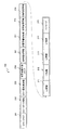
図8はパケット送信部109の構成の一例を示すブロック図である。パケット送信部109は、パケット情報260またはパケット情報270のミラーフラグ231に基づいて当該パケットがミラーパケットであるか否かを判定するミラーパケット判定部1091と、ミラーパケットに対するポリシングを行うミラーポリシング部1092と、ミラーパケットに対するシェーピングを行うミラーシェーピング部1093と、ミラーパケットに対するサンプリングを行うミラーサンプリング部1094と、ミラーパケットを送信するミラーポート132−1〜132−nと、ミラーパケットでない中継パケットにシェーピングを行いシェーピング部1095と、中継パケットを送信する出力ポート131から構成される。
FIG. 8 is a block diagram illustrating an example of the configuration of the
パケット送信部109に入力されたパケット情報260またはパケット情報270のミラーフラグ231が「有効」を示す値である場合には、当該パケット情報260はミラーパケットであるとミラーパケット判定部1091で判定し、ミラーポート情報232と、ミラー優先度情報233と、攻撃情報付加フラグ234と、攻撃種別情報221と、攻撃影響度情報222と、攻撃確度情報223と、攻撃経路情報224に基づいてミラーポリシング部1092でのポリシングと、ミラーシェーピング部1093でのシェーピングと、ミラーサンプリング部1094でのサンプリングを行い、ミラーポート132からミラー回線へ出力する。
When the
パケット送信部109に入力されたパケット情報260またはパケット情報270のミラーフラグ231が「無効」を示す値である場合には、当該パケット情報270は中継パケットであるとミラーパケット判定部1091で判定し、シェーピング部1095でシェーピングを行い、出力ポート131から出力回線へ出力する。
When the
次に、各処理部の構成と処理の詳細を説明する。 Next, the configuration and processing details of each processing unit will be described.
受信側セキュリティ判定部103または送信側セキュリティ判定部107の攻撃種別判定部1031において判定する攻撃種別または攻撃予兆種別には、以下がある。
Examples of the attack type or the attack predictor type determined by the receiving side
(1)Logic攻撃:計算機システムの脆弱性を利用する攻撃と判定する条件(Byte長に関する条件を含む)を登録したLogic攻撃リストに一致したパケットをLogic攻撃と判定する。 (1) Logic attack: A packet that matches a logic attack list in which a condition (including a condition related to the byte length) that is determined to be an attack that uses the vulnerability of the computer system is registered is determined as a logic attack.
(2)フィルタパケット:パケット中継装置100の管理者またはアナライザから送信されたパケット中継装置100宛の設定指示に関するパケットの指示で定義したフィルタ廃棄すべきフロー(パケット情報200に関する条件で定まるパケットの集合)の条件を登録したフィルタリスト(ACL(Access Control List))に一致したパケットをフィルタパケット(ユーザ登録の攻撃)と判定する。
(2) Filter packet: a flow to be discarded by a filter defined by a packet instruction related to a setting instruction addressed to the
(3)送信元詐称攻撃:パケットの送信元アドレスに関する情報が詐称であるとuRPF(unicast Reverse Path Forwarding)等の手段で判定したパケットを送信元詐称攻撃と判定する。送信元詐称攻撃は、大規模なDDoS攻撃の予兆とも考えられる。 (3) Source spoofing attack: A packet determined by means such as uRPF (unicast Reverse Path Forwarding) is determined to be a source spoofing attack if the information regarding the source address of the packet is spoofing. The transmission source spoofing attack is also considered as a sign of a large-scale DDoS attack.
(4)フラッド攻撃:フローの帯域が、パケット中継装置100の管理者またはアナライザから送信されたパケット中継装置100宛の設定指示に関するパケットの指示で定義した監視帯域(または帯域のしきい値)を超過すると、フラッド攻撃と判定する。監視帯域として、軽度監視帯域と重度監視帯域を設け、フラッド攻撃の影響度の重度、軽度を判定する構成とすることもできる。
(4) Flood attack: The bandwidth of the flow is a monitoring bandwidth (or bandwidth threshold value) defined by a packet instruction related to a setting instruction addressed to the
(5)攻撃予兆:フローの統計値や帯域の時間的変動が通常と大きく異なる場合、攻撃予兆と判定する。あるいは、複数の宛先IPアドレスの特定の宛先ポートに関する連続アクセスはホストスキャン、特定の宛先IPアドレスの複数の宛先ポートに関する連続アクセスはポートスキャンと呼ばれる。これらのスキャンは標的への侵入を試みる攻撃予兆として知られている。なお、ホストスキャンやポートスキャンの検出については非特許文献2の技術を適用することができる。 (5) Predictive attack: When the statistical value of the flow or the temporal variation of the bandwidth is significantly different from the normal, it is determined as the predictive attack. Alternatively, continuous access for a specific destination port of a plurality of destination IP addresses is called host scan, and continuous access for a plurality of destination ports of a specific destination IP address is called port scan. These scans are known as predictive attacks that attempt to penetrate the target. Note that the technique of Non-Patent Document 2 can be applied to detection of host scan and port scan.
なお、通常のフローの統計値は、パケット中継装置100の図示しない統計機能によって蓄積される。統計値としては、例えば、時間帯毎の宛先IPアドレスや送信元IPアドレスやポート番号や帯域を時間帯毎に平均値などを算出して蓄積しておく。そして、パケット中継装置100は、現在の統計値と過去の同じ時間帯の統計値が所定の閾値を超えて変化していれば、通常と大ききが異なると判定することができる。
Note that the statistical value of the normal flow is accumulated by a statistical function (not shown) of the
また、パケット中継装置100の統計機能は、フローやパケットの特徴量や特徴パターンを蓄積することができ、例えば、特徴量としてはパケットのバイト長や、パケット(またはフロー)の帯域や、統計量を用いることができる。また、特徴パターンとしては、パケットの宛先IPアドレスやポート番号と時間帯毎のアクセス数などの情報を用いることができる。
The statistical function of the
図9は攻撃種別判定部1031の構成の一例を示すブロック図である。
FIG. 9 is a block diagram illustrating an example of the configuration of the attack
攻撃種別判定部1031は、パケットがLogic攻撃であるか否かを判定するLogic攻撃判定部10311と、パケットがフィルタリストに一致するか否かを判定するフィルタパケット判定部10312と、パケットの送信元アドレスが詐称されているか否かを判定する送信元詐称攻撃判定部10313と、フローの帯域またはバースト量(バーストトラフィックのデータ量)が一定値を超過するか否かを判定するフラッド攻撃判定部10314と、パケットのアクセスの特徴、統計値、帯域の時間的変動に基づいてパケットが攻撃予兆であるか否かを判定する攻撃予兆判定部10315と、上記(1)〜(5)の攻撃種別または攻撃予兆種別の複数で一致すると判定された場合に、攻撃種別または攻撃予兆種別の優先度に基づいていずれの攻撃種別または攻撃予兆種別であるかを判定する攻撃種別優先度判定部10316から構成される。
The attack
本実施例では、Logic攻撃の優先度が最も高く、以下フィルタパケット、送信元詐称攻撃、フラッド攻撃、攻撃予兆の順の優先度になっているものとする。なお、この優先度は攻撃の影響度、確度の高い順となっていることが望ましい。攻撃種別判定部1031にパケット情報200が入力されると、パケット情報200はLogic攻撃判定部10311と、フィルタパケット判定部10312と、送信元詐称攻撃判定部10313と、フラッド攻撃判定部10314と、攻撃予兆判定部10315に各々入力される。
In this embodiment, it is assumed that the priority of the logic attack is the highest, and the priority is the order of the filter packet, the transmission source spoofing attack, the flood attack, and the attack predictor. Note that it is desirable that the priorities are in order of attack impact and accuracy. When the
図中10311〜10315の各判定部で攻撃種別に関する判定が行われると、判定結果が攻撃種別優先度判定部10316に入力される。攻撃種別優先度判定部10316で、各攻撃種別の優先度に基づいて攻撃種別を判定し、判定結果をパケット情報250の攻撃種別情報221として出力する。例えば、パケット情報200がLogic攻撃とフラッド攻撃の両方に該当すると判定された場合は、当該パケットの攻撃種別はLogic攻撃であると判定する。
When determination regarding the attack type is performed by each of the
図10はLogic攻撃判定部10311の構成の一例を示すブロック図である。Logic攻撃判定部10311は、Logic攻撃と判定する条件を設定したLogic攻撃エントリ1(103111)〜Logic攻撃エントリn(10311n)から構成されるLogic攻撃テーブル103110を含む。
FIG. 10 is a block diagram illustrating an example of the configuration of the logic
Logic攻撃判定部10311は、パケット情報200が入力されると、パケット情報200のうち所定の情報が、Logic攻撃エントリ1(103111)〜Logic攻撃エントリn(10311n)の条件に一致するか逐次比較する。一致したエントリがある場合はパケット情報200の攻撃種別はLogic攻撃であると判定する。
When the
Logic攻撃エントリの条件は、条件値による比較だけではなく比較式、等号式による論理的な判定も含む。例えば、Land攻撃をLogic攻撃として設定する場合は、L3情報212の送信元IPアドレス=宛先IPアドレスという等号式による条件となる。また、Ping of death攻撃をLogic攻撃として設定する場合は、L3情報212のフラグメントオフセットとペイロード215のByte長の和が一定値より大きい、という比較式となる。
The condition of the logic attack entry includes not only a comparison by a condition value but also a logical determination by a comparison expression and an equality expression. For example, when a Land attack is set as a Logic attack, the condition is based on the equality equation that the source IP address of the
上記の他にも、Invalid TCP Flags攻撃をLogic攻撃として設定する場合は、TCP(Transmission Control Protocol)フラグの有り得ない組み合わせをLogic攻撃エントリの条件としてLogic攻撃テーブル103110に設定する。パケット情報200が一致したLogic攻撃エントリがLand攻撃の設定である場合のパケット情報200の攻撃種別はLogic攻撃(Land攻撃)、パケット情報200が一致したLogic攻撃エントリがPing of death攻撃の設定である場合のパケット情報200の攻撃種別はLogic攻撃(Ping of death攻撃)、パケット情報200が一致したLogic攻撃エントリがTCP Invalid Flags攻撃の設定である場合のパケット情報200の攻撃種別はLogic攻撃(TCP Invalid Flags攻撃)となる。
In addition to the above, when an Invalid TCP Flags attack is set as a Logic attack, a combination that does not have a TCP (Transmission Control Protocol) flag is set in the Logic attack table 103110 as a condition of the Logic attack entry. When the logic attack entry that matches the
以上のように、パケットの特徴量(Byte長)や特徴パターンを攻撃エントリに登録しておき、パケット情報200と比較することで、Logic攻撃のパケットを特定することができる。
As described above, a packet of a logic attack can be specified by registering a feature amount (byte length) or a feature pattern of a packet in an attack entry and comparing it with the
図11はフィルタパケット判定部10312の構成の一例を示すブロック図である。フィルタパケット判定部10312は、フィルタパケットと判定する条件を設定したフィルタエントリ1(103121)〜フィルタエントリn(10312n)から構成されるフィルタテーブル(検索テーブル)103120を含む。
FIG. 11 is a block diagram illustrating an example of the configuration of the filter
フィルタパケット判定部10312はパケット情報200が入力されると、パケット情報200のうちフィルタエントリとの一致比較の判定に必要な条件を、フィルタエントリ1(103121)〜フィルタエントリn(10312n)の条件と逐次比較し、一致したフィルタエントリのある場合はパケット情報200の攻撃種別はフィルタパケットの条件であると判定する。
When the
一致したフィルタエントリがフィルタエントリn(10312n)である場合の攻撃種別は、フィルタパケット(フィルタエントリn)となる。フィルタエントリの条件は、パケット情報200のL2情報211、L3情報212、L4情報213、L7情報214の条件によりパケット中継装置100が管理端末121経由で、またはアナライザ300から送信されたパケット中継装置100宛の設定指示に関するパケットの指示で制御CPU120がフィルタテーブル103120に設定する。
The attack type when the matched filter entry is filter entry n (10312n) is a filter packet (filter entry n). The filter entry condition is that the
以上のように、フィルタパケット判定部10312はフィルタテーブル(検索テーブル)103120の特徴パターンから攻撃のパケットを特定することができる。
As described above, the filter
図12に送信元詐称攻撃判定部10313と受信側パケット処理部102の構成の一例を示すブロック図である。送信元詐称攻撃判定部10313は、送信元経路検索要求部103131と送信元詐称判定部103132から構成される。受信側パケット処理部102は、IPアドレス1に対する出力回線を設定した経路エントリ1(IP1)10201〜経路エントリn(IPアドレスn)に対する出力ポートを設定した経路エントリn(IPn)1020nを含む経路テーブル1020から構成される。
FIG. 12 is a block diagram illustrating an example of the configuration of the transmission source spoofing
受信側パケット処理部102は、パケット情報200のL3情報212の宛先IPアドレスに対応する経路エントリ(経路テーブル1020)を参照し、この宛先IPアドレスに対する出力ポート131の情報を得る。パケット情報200が送信元詐称攻撃判定部10313に入力されると、送信元経路検索要求部103131でパケット情報200の入力ポート情報201とL3情報212の送信元IPアドレスを抽出して、受信側パケット処理部102に出力する。
The reception-side
受信側パケット処理部102に送信元IPアドレスが入力されると、この送信元IPアドレスに対する経路エントリn(IPn)を参照し、この送信元IPアドレスに対する出力ポート131の情報を得る。パケット情報200の入力ポート情報201と、送信元IPアドレスで経路テーブル1020を参照して得られた出力ポート情報202を送信元詐称攻撃判定部10313に入力し、送信元詐称判定部103132で入力ポート情報201と出力ポート情報202の一致比較をし、一致していない場合はパケット情報200の攻撃種別は送信元詐称攻撃(送信元IPアドレス値)と判定する。
When the transmission source IP address is input to the reception side
以上のように、送信元詐称攻撃判定部10313は送信元IPアドレスの特徴パターンから送信元詐称攻撃のパケットを特定することができる。
As described above, the transmission source spoofing
図13は、フラッド攻撃判定部10314の構成の一例を示すブロック図である。フラッド攻撃判定部10314では、パケット中継装置100の管理者またはアナライザ300から送信されたパケット中継装置100宛の設定指示に関するパケットの指示で定義したフロー毎にフラッド攻撃発生と判定する監視帯域(または閾値)を設定し、フロー毎の帯域が監視帯域を超過したパケット情報200の攻撃種別をフラッド攻撃と判定する。
FIG. 13 is a block diagram illustrating an example of the configuration of the flood
フラッド攻撃判定部10314は、パケット中継装置100の管理者またはアナライザ300から送信されたパケット中継装置100宛の設定指示に関するパケットの指示で定義したフロー毎の条件を設定するフローエントリ1(1031401)〜フローエントリn(103140n)から構成されるフローテーブル103140と、各フローエントリに対応する監視帯域と各フローの帯域が監視帯域を超過するか否かを判定するための情報を含む帯域エントリ1(1031411)〜帯域エントリn(103141n)から構成される帯域テーブル103141と、帯域判定部103142から構成される。
The flood
フラッド攻撃判定部10314は、パケット情報200が入力されると、パケット情報200のうちフローエントリ(フローテーブル103140)との一致比較の判定に必要な条件がフローエントリ1(1031401)〜フローエントリn(103140n)の条件に一致するか逐次比較し、フローエントリnと一致した場合は当該パケット情報200はフローエントリnに属し、フローエントリnに対応する帯域エントリn(103141n)を参照する。
When the
帯域エントリn(103141n)から監視帯域と各フローの帯域が監視帯域を超過するか否かを判定するための情報を読み出すと、帯域判定部103142でパケット情報200が監視帯域を超過するか否かを判定する。監視帯域を超過する場合は、パケット情報200の攻撃種別はフラッド攻撃(フローn)と判定する。
When information for determining whether or not the monitoring bandwidth and the bandwidth of each flow exceed the monitoring bandwidth is read from the bandwidth entry n (103141n), whether or not the
監視帯域として、軽度監視帯域と重度監視帯域を設ける場合は、重度監視帯域の値を軽度監視帯域の値より大きいものとし、軽度監視帯域を超過し、かつ重度監視帯域を超過しない場合はパケット情報200の攻撃種別は軽度フラッド攻撃(フローn)と判定し、重度監視帯域を超過する場合はパケット情報200の攻撃種別は重度フラッド攻撃(フローn)と判定する。
When providing a light monitoring band and a heavy monitoring band as monitoring bands, the value of the heavy monitoring band should be greater than the value of the light monitoring band. If the light monitoring band is exceeded and does not exceed the heavy monitoring band, the packet information The
以上のように、フラッド攻撃判定部10314は、フローの特徴量からフラッド攻撃のパケットを特定することができる。
As described above, the flood
図14は攻撃予兆判定部10315の構成の一例を示すブロック図である。攻撃予兆判定部10315は、パケット中継装置100の管理者またはアナライザ300から送信されたパケット中継装置100宛の設定指示に関するパケットの指示で定義したフロー毎の条件を設定するフローエントリ1(1031501)〜フローエントリn(103150n)から構成されるフローテーブル103150と、各フローエントリに対応するパケット数、Byte数等の統計値を採取する統計値1と、統計値1に関するアラートを設定するアラート1で構成される統計エントリ1(1031511)〜統計エントリn(103151n)から構成される統計テーブル103151と、攻撃予兆判定部103152から構成される。
FIG. 14 is a block diagram illustrating an example of the configuration of the attack
制御CPU120は統計テーブル103151を周期的に読み出し、読み出したフローの統計値の時間的変動が異常に大きい場合(例えば、読み出したフローのSYNパケットのカウント数が急激に増加している場合、SYNフラッド攻撃の可能性有り)、または複数の宛先IPアドレスの特定の宛先ポートに関する連続アクセスによるホストスキャンの可能性を示す特徴的な統計値である場合、または特定の宛先IPアドレスの複数の宛先ポートに関する連続アクセスによるポートスキャンの可能性を示す特徴的な統計値である場合、または到達可能なIPアドレスのうちホスト未割当の未使用のIPアドレス(ダークネット)へのアクセスがある場合(ホストスキャンを含めた攻撃活動、不正行為に起因するアクセスが大半)、ICMP(Internet Control Message Protocol)による異常メッセージを検知した場合(ICMPのhost unreachable、port unreachable、time exceeded等のメッセージで、攻撃に起因する可能性のあるアクセス異常、経路異常等を検知)等、攻撃予兆と考えられる特徴的な統計値のパターンまたはアクセスパターンを検知した場合は、読み出したフローのアラートフィールドに警告を示す値を設定する。
The
攻撃予兆と考えられる事象が一定時間以上検知されなくなった場合は、統計テーブル103151に警告を設定したフローのアラートフィールドに警告を示さない値を設定しても良い。プロトコル動作の異常性から攻撃を検知する場合は、統計値の時間的変動の判定に用いる時間スケールを、プロトコル動作に特徴的な時間スケールとする。例えば、TCPの挙動は往復遅延時間RTT(Round Trip Time)に依存するので、RTT程度の時間オーダーで統計値の時間的変動を判定する。 When an event considered to be an attack symptom is not detected for a certain period of time, a value that does not indicate a warning may be set in the alert field of the flow for which a warning is set in the statistical table 103151. When an attack is detected from the abnormalities of the protocol operation, the time scale used for determining the temporal fluctuation of the statistical value is set as a time scale characteristic of the protocol operation. For example, since the behavior of TCP depends on the round trip time RTT (Round Trip Time), the temporal variation of the statistical value is determined in a time order of about RTT.
また、DDoS攻撃を検知する場合は攻撃予兆判定部10315が、統計値の時間的変動の判定に用いる時間スケールを、平均的な攻撃継続時間とする。例えば、平均的な攻撃持続時間が1日程度であれば1日程度の時間オーダーで統計値の時間的変動を判定する。あるいは、平均的な攻撃持続時間が1時間程度であれば、攻撃予兆判定部10315は、1時間程度の時間オーダーで統計値の時間的変動を判定する。
In addition, when detecting a DDoS attack, the attack
攻撃予兆判定部10315はパケット情報200が入力されると、パケット情報200のうちフローエントリとの一致比較の判定に必要な条件がフローエントリ1(1031501)〜フローエントリn(103150n)の条件に一致するか逐次比較し、フローエントリnと一致した場合は当該パケット情報200はフローエントリnに属し、フローエントリnに対応する統計エントリn(103151n)を参照する。
When the
攻撃予兆判定部10315は参照する統計値の種別に応じてパケット情報200のパケット数またはByte数を統計値nに加算する。参照した統計エントリn(103151n)のアラートフィールドが警告を示す値である場合には、攻撃予兆判定部103152でパケット情報200の攻撃種別は攻撃予兆(フローn)と判定する。
The attack
以上のように、攻撃予兆判定部10315は、統計情報やフローの特徴量または特徴パターンから攻撃予兆のパケットまたは可能性のあるパケットを特定することができる。
As described above, the attack
図15は、受信側セキュリティ判定部103の攻撃影響度判定部1032の構成の一例を示すブロック図である。攻撃影響度判定部1032は、パケット中継装置100の管理者またはアナライザ300から送信されたパケット中継装置100宛の設定指示に関するパケットの指示で定義した攻撃種別毎の攻撃影響度を設定する攻撃影響度エントリ1(103211)〜攻撃影響度エントリn(10321n)から構成される攻撃影響度テーブル10321から構成される。
FIG. 15 is a block diagram illustrating an example of the configuration of the attack
攻撃影響度とは、攻撃による被害の影響度の軽重のレベルを表す指標であり、攻撃予兆は実際の攻撃に至っていないので攻撃影響度は軽い、フラッド攻撃の中でも監視帯域の大きいフローの方が監視帯域の小さいフローよりも攻撃影響度は重い等、パケット中継装置100の管理者またはアナライザ300から送信されたパケット中継装置100宛の設定指示に関するパケットの指示で定義したポリシーに基づいて攻撃種別毎の攻撃影響度を管理端末121から設定することができる。
Attack impact is an indicator of the severity of the impact of damage caused by an attack. Since the predictive attack has not reached the actual attack, the attack impact is low. For each attack type, based on the policy defined by the packet instruction relating to the setting instruction addressed to the
攻撃種別判定部1031で判定された攻撃種別情報221が攻撃影響度判定部1032に入力されると、攻撃種別情報221に対応した攻撃影響度テーブル10321の攻撃影響度エントリ1(103211)〜攻撃影響度エントリn(10321n)を参照する。攻撃影響度エントリ1(103211)には攻撃種別情報221に対応した攻撃影響度が予め設定されており、攻撃影響度の判定結果をパケット情報250の攻撃影響度情報222として出力する。
When the
図16は、受信側セキュリティ判定部103の攻撃確度判定部1033の構成の一例を示すブロック図である。攻撃確度判定部1033は、パケット中継装置100の管理者またはアナライザ300から送信されたパケット中継装置100宛の設定指示に関するパケットの指示で定義した攻撃種別毎の攻撃確度を設定する攻撃確度エントリ1(103311)〜攻撃確度エントリn(10331n)から構成される攻撃確度テーブル10331から構成される。
FIG. 16 is a block diagram illustrating an example of the configuration of the attack
攻撃確度とは、攻撃可能性に関する確からしさの高低のレベルを表す指標であり、攻撃予兆は実際の攻撃に至っていないので攻撃確度は低い、フラッド攻撃には攻撃の疑いのある通信と、攻撃の疑いのない正常な通信が混在しているのに対し、Logic攻撃は通常有り得ない異常なパケットヘッダの特徴を持っており確定的な攻撃と考えられるのでLogic攻撃の方が攻撃確度は高い。また、フラッド攻撃の中でも監視帯域の大きいフローの方が監視帯域の小さいフローよりも攻撃確度は高い等、パケット中継装置100の管理者またはアナライザ300から送信されたパケット中継装置100宛の設定指示に関するパケットの指示で定義したポリシーに基づいて攻撃種別毎の攻撃確度を管理端末121から設定することができる。
The attack accuracy is an index that indicates the level of probability of attack possibility, and since the attack predictor has not reached the actual attack, the attack accuracy is low. While there is a mixture of unquestionable normal communications, a logic attack has a characteristic of an abnormal packet header that is not normally possible and is considered a definite attack, so a logic attack has a higher attack accuracy. In addition, among the flood attacks, a flow with a large monitoring bandwidth has a higher attack accuracy than a flow with a small monitoring bandwidth. For example, the setting instruction addressed to the
攻撃種別判定部1031で判定された攻撃種別情報221が攻撃確度判定部1033に入力されると、攻撃種別情報221に対応した攻撃確度テーブル10331の攻撃確度エントリ1(103311)〜攻撃確度エントリn(10331n)を参照する。攻撃確度エントリ1〜nには攻撃種別情報221に対応した攻撃確度が設定されており、攻撃確度の判定結果をパケット情報250の攻撃確度情報223として出力する。
When the
攻撃経路情報224とは、入力ポート情報201と出力ポート情報202により構成される攻撃経路を特定するための情報であり、受信側セキュリティ判定部103において、パケット情報200のうち入力ポート情報201と出力ポート情報202をパケット情報250の攻撃経路情報224として出力する。
The
以上の受信側セキュリティ判定部103の判定処理が完了すると、攻撃種別情報221と、攻撃影響度情報222と、攻撃確度情報223と、攻撃経路情報224を含むパケット情報250(図5参照)が受信側ミラー処理部104に入力される。
When the determination processing of the receiving side
受信側ミラー処理部104の構成図は図6で説明した通りである。
The configuration diagram of the receiving side
図17は受信側ミラー処理部104のミラーポート判定部1041の構成の一例を示すブロック図である。ミラーポート判定部1041は、パケット情報250の攻撃種別情報221と攻撃影響度情報222と攻撃確度情報223と攻撃経路情報224の組み合わせ毎にミラーする、または、しないを設定するミラーイネーブルと、ミラーポート132と、ミラー優先度を設定するミラーエントリ1(104111)〜ミラーエントリn(10411n)から構成されるミラーテーブル10411を含む。なお、ミラーイネーブルは、イネーブルがミラーパケットの生成を示し、ディスエーブルがミラーパケットを生成しないことを示す。
FIG. 17 is a block diagram illustrating an example of the configuration of the mirror
ミラーポート判定部1041にパケット情報250が入力されると、パケット情報250の攻撃種別情報221と攻撃影響度情報222と攻撃確度情報223と攻撃経路情報224に対応するミラーエントリ1(104111)〜ミラーエントリn(10411n)を参照し、当該パケット情報250に対するミラーイネーブル、ミラーポート、ミラー優先度を読み出して、ミラーポート判定部1041〜受信ミラーパケット生成部1043におけるパケット情報280(図21参照)のミラーフラグ231にミラーイネーブルが書き込まれる。
When the
図21において、ミラーフラグ231がミラー可(イネーブル)を示す値である場合は、ミラーポート情報232にミラーポート132を設定し、ミラー優先度情報233にミラー優先度を設定し、攻撃情報付加フラグ234は後述の攻撃情報付加判定部1042で設定される値であり、その他のフィールドはパケット情報250の値を書き込む。
In FIG. 21, when the
ミラーフラグ231がミラー否(ディスエーブル)を示す値である場合は、ミラーポート情報232とミラー優先度情報233は参照されない値であり、攻撃情報付加フラグは攻撃情報を付加しないことを示す値とし、その他のフィールドはパケット情報250の値を書き込む。
When the
ミラーテーブル10411の設定に関し、例えばアナライザ300毎の性能に応じて負荷を抑制するため、パケット中継装置100の管理者またはアナライザ300から送信されたパケット中継装置100宛の設定指示に関するパケットの指示で解析の重要度が高いと判断する攻撃種別のパケットだけをミラーする設定とする、あるいは、攻撃影響度の高いパケットをミラーする設定とする、あるいは、攻撃確度の高いパケットだけをミラーする設定とする、あるいは性能の高いアナライザ300を接続したミラーポート132を設定したミラーエントリは全てミラーする設定とする運用が考えられる。
Regarding the setting of the mirror table 10411, for example, in order to suppress the load according to the performance of each
また、DDoS攻撃に用いられるフラッド攻撃に対してはDDoS攻撃対策装置(図示省略)を接続したミラーポート132を設定し、その他の攻撃に対しては別のミラーポート132を設定することで、攻撃種別に応じた最適なアナライザ300にパケットをミラーする構成とする運用が考えられる。
In addition, a
図18は攻撃情報付加判定部1042の構成の一例を示すブロック図である。攻撃情報付加判定部1042は、ミラーポート判定部1041で判定したミラーポート毎に攻撃種別情報221と攻撃影響度情報222と攻撃確度情報223と、攻撃経路情報224をミラーパケットに付加するか否かを設定する攻撃情報付加フラグ1(104211)〜攻撃情報付加フラグn(10421n)から構成される攻撃情報付加テーブル10421を含む。
FIG. 18 is a block diagram illustrating an example of the configuration of the attack information
ミラーポート判定部1041で判定したミラーポート情報が攻撃情報付加判定部1042に入力されると、パケット情報280のミラーフラグ231がミラー可を示す値である場合は、ミラーポート132に対応した攻撃情報付加テーブル10421の攻撃情報付加フラグ1(104211)〜攻撃情報付加フラグn(10421n)を読み出し、パケット情報280の攻撃情報付加フラグ234に読み出した攻撃情報付加フラグの内容を書き込む。
When the mirror port information determined by the mirror
パケット情報280のミラーフラグ231がミラー否を示す値である場合は、攻撃情報付加テーブル10421を読み出す処理はせず、パケット情報280の攻撃情報付加フラグ234は攻撃情報を付加しないことを示す値のままとする。
When the
図19は、受信ミラーパケット生成部1043の構成の一例を示すブロック図である。受信ミラーパケット生成部1043は、ミラーポート判定部1041で判定したミラーフラグ231に基づいてミラーパケットの生成を指示するミラー判定部10431と、ミラー判定部10431の指示に基づいてミラーパケットを生成するミラーパケット生成部10432から構成される。
FIG. 19 is a block diagram illustrating an example of the configuration of the reception mirror
受信ミラーパケット生成部1043にパケット情報280が入力されると、パケット情報280のミラーフラグ231に基づいてミラー判定部10431でミラーイネーブル、つまりパケットを生成するか否かを判定する。ミラーフラグ231がミラー可を指示する値である場合は、ミラーパケット生成部10432でパケット情報260(図7参照)をコピーし、コピーしたパケット情報280のうち出力ポート情報202と優先度情報203を削除したパケット情報260をミラーパケットとしてパケット中継処理部105に出力する。
When the
ミラーパケットのコピー元であるオリジナルの受信パケットに対しては、上述のミラーパケットのパケット情報260とは独立して、パケット情報280(図21参照)のミラーフラグ231を「無効」を示す値とし、ミラーポート情報232と、ミラー優先度情報233と、攻撃情報付加フラグ234と、攻撃種別情報221と、攻撃影響度情報222と、攻撃確度情報223と、攻撃経路情報224を削除したパケット情報270をパケット中継処理部105に出力する。
For the original received packet that is the copy source of the mirror packet, the
ミラーポート判定部1041でミラーパケットを生成しないと判定した場合は受信ミラーパケットを生成せず、パケット情報280のミラーフラグ231を「無効」を示す値とし、ミラーポート情報232と、ミラー優先度情報233と、攻撃情報付加フラグ234と、攻撃種別情報221と、攻撃影響度情報222と、攻撃確度情報223と、攻撃経路情報224を削除したパケット情報270をパケット中継処理部105に出力する。
If the mirror
パケット中継処理部105から送信側パケット処理部106に入力したパケット情報260またはパケット情報270は、先述の通り送信側セキュリティ判定部107と、送信側ミラー処理部108での処理と判定を行い、パケット送信部109に入力される。
The
パケット送信部109に入力されたパケット情報260またはパケット情報270は、ミラーパケット判定部1091でミラーフラグ231の判定を行い、ミラーフラグ231がミラー可を示す値である場合は、ミラーパケットのパケット情報260であると判定し、パケット情報260をミラーポリシング部1092に出力してミラーパケットの帯域を制限する。
The
次にパケット送信部109では、パケット情報260をミラーシェーピング部1093に入力して、ミラーパケットの帯域を制限すると共に平滑化する。次に、パケット情報260をミラーサンプリング部1094に入力して、指定のサンプルレートに従う比率のミラーパケットを転送し、残りを廃棄する。ミラーフラグ231がミラー否を示す値である場合は、ミラーパケットではないパケット情報270であると判定し、パケット情報270をシェーピング部1095に出力する。
Next, the
図22はミラーポリシング部1092の構成の一例を示すブロック図である。ミラーポリシング部1092は、ミラーポート132毎の制限帯域を設定した帯域エントリ1(109211)〜帯域エントリn(10921n)から構成される帯域テーブル10921と、帯域判定部10922から構成される。
FIG. 22 is a block diagram showing an example of the configuration of the
帯域テーブル10921のミラーポート132毎の制限帯域は、パケット中継装置100の管理者またはアナライザ300から送信されたパケット中継装置100宛の設定指示に関するパケットの指示で制御CPU120が設定する。
The limited bandwidth for each
ミラーポリシング部1092は、パケット情報260が入力されると、パケット情報260のミラーポート情報232に対応する帯域エントリ1(109211)〜帯域エントリn(10921n)を参照する。ミラーポリシング部1092は、帯域エントリ1(109211)〜帯域エントリn(10921n)の中から監視帯域と各ミラーポート132の帯域が監視帯域を超過するか否かを判定するための情報を読み出すと、帯域判定部10922でパケット情報260が監視帯域を超過するか否かを判定する。
When the
監視帯域は、パケット中継装置100の管理者またはアナライザ300から送信されたパケット中継装置100宛の設定指示に関するパケットの指示で制御CPU120が設定する。監視帯域を超過する場合、ミラーポリシング部1092はパケット情報260を転送せずに廃棄する。監視帯域を超過しない場合、ミラーポリシング部1092はパケット情報260をミラーシェーピング部1093に入力する。
The monitoring bandwidth is set by the
図23はミラーシェーピング部1093の構成の一例を示すブロック図である。ミラーシェーピング部1093は、いずれのキューにパケット情報260を蓄積するか判定するキュー蓄積判定部10931と、ミラーポート132毎に4キューを備えるキュー10932と、ミラーポート132毎の出力帯域を設定した帯域エントリ1(109331)〜帯域エントリn(10933n)から構成される帯域テーブル10933と、出力するタイミングを判定する出力判定部10934から構成される。
FIG. 23 is a block diagram illustrating an example of the configuration of the
帯域テーブル10933のミラーポート132毎の出力帯域は、パケット中継装置100の管理者またはアナライザ300から送信されたパケット中継装置100宛の設定指示に関するパケットの指示で制御CPU120が設定する。
The output bandwidth for each
ミラーシェーピング部1093にパケット情報260が入力されると、パケット情報260のうちミラーポート情報232とミラー優先度情報233に対応するキューをキュー蓄積判定部10931で判定し、キュー蓄積判定部10931は判定したキューにパケット情報260を蓄積する。例えばミラーポート情報がミラーポート1(132−1)であり、ミラー優先度情報がキュー2である場合、キュー2(ミラーポート1)1093212のキューにパケット情報260を蓄積する。
When the
一方、パケット情報260のミラーシェーピング部1093への入力タイミングとは独立して、出力判定部10934はミラーポート132毎の出力帯域を設定した帯域テーブル10933を参照してミラーポート132毎の出力帯域を判定し、シェーピング後のミラーパケットの帯域がバーストせずに平滑なトラフィックとなるように、ミラーポート132毎の出力帯域から次にパケット情報260を出力すべきミラーポート132と出力するタイミングを判定する。
On the other hand, independent of the input timing of the
出力判定部10934は、出力すべきタイミングで、出力すべきミラーポート132の複数のキュー10932にパケットが蓄積されている場合は、キュー(j)の(j)の値が小さいキューからパケット情報260を出力する。これにより、ミラー優先度情報233に基づいたミラーパケットの送信に関する優先制御を実現する。
When the packet is accumulated in the plurality of
図24はミラーサンプリング部1094の構成の一例を示すブロック図である。ミラーサンプリング部1094は、攻撃種別情報221と、攻撃影響度情報222と、攻撃確度情報223と、攻撃経路情報224毎のサンプルレートを設定したサンプルレートエントリ1(109411)〜サンプルレートエントリn(10941n)から構成されるサンプルレートテーブル10941と、サンプリングした結果のパケット情報260を出力するか否か判定するサンプリング判定部10942から構成される。
FIG. 24 is a block diagram illustrating an example of the configuration of the
サンプルレートテーブル10941の攻撃種別情報221と、攻撃影響度情報222と、攻撃確度情報223と、攻撃経路情報224毎のサンプルレートは、パケット中継装置100の管理者またはアナライザ300から送信されたパケット中継装置100宛の設定指示に関するパケットの指示で制御CPU120が設定する。
The
例えば、フラッド攻撃の負荷が高くなった場合は、サンプルレートを低くしないとアナライザ300に対する負荷も高くなってしまう。そこで、パケット送信部109はアナライザ300が受信するミラーパケットの負荷に応じて、アナライザ300からパケット中継装置100のサンプルレートを調整する指示パケットを発行する運用が考えられる。
For example, if the flood attack load increases, the load on the
または、パケット中継装置100の統計機能(図示省略)を用いて制御CPU120でフラッド攻撃の負荷を監視して、パケット中継装置100で自律的に負荷に応じたサンプルレートに調整する運用が考えられる。サンプルレートの決定方法としては例えば、フラッド攻撃と判定する帯域を基準として、負荷がこの基準に対し2^nとなる閾値を上回る毎にサンプルレートの値を変更前の(1/2)^n倍に変更すれば、アナライザ300に対する負荷がフラッド攻撃発生時の2倍未満に抑えることができる。
Alternatively, an operation in which the
逆に、負荷が減少した場合はサンプルレートを高くすることによってアナライザ300に対する負荷が過大とならない範囲で監視対象とするパケット量を保つことができる。例えば、フラッド攻撃と判定する帯域を基準として、負荷がこの基準に対し2^nとなる閾値を下回る毎にサンプルレートの値を変更前の2^n倍に変更すれば、アナライザ300の分析対象とするミラーパケットの量を、アナライザ300に対する負荷がフラッド攻撃発生時以上に保つことができる。
Conversely, when the load decreases, the amount of packets to be monitored can be maintained within a range where the load on the
ミラーサンプリング部1094は、パケット情報260が入力されると、パケット情報260の攻撃種別情報221と、攻撃影響度情報222と、攻撃確度情報223と、攻撃経路情報224に対応するサンプルレートエントリ1(109411)〜サンプルレートエントリn(10941n)を参照し、パケット情報260に対するサンプルレートをサンプリング判定部10942に出力する。
When the
サンプリング判定部10942は、サンプルレートエントリ毎のサンプルカウンタ1(109421)〜サンプルカウンタn(10942n)から構成されるサンプルカウンタテーブル109421を含む。
The
パケット情報260に対応するサンプルレートとパケット情報260がサンプリング判定部10942に入力されると、サンプリング判定部10942はサンプルカウンタに1を加算して、対応するサンプルカウンタを参照して、パケット情報260を出力するか否かを判定する。例えばサンプルレートが1/4である場合は、サンプルカウンタが3になるとパケット情報260を出力してサンプルカウンタを0にラップし、サンプルカウンタが3以外の値となる場合はパケット情報260を出力しない判定とすれば、サンプルレートでパケット情報260を出力するサンプリングの制御を実現できる。
When the sample rate corresponding to the
以上の処理により、アナライザ300に対する負荷が過大になるのを防ぎ、また、負荷の低下が過大になるのを防いでアナライザ300に対する負荷を適正に保つことができる。
With the above processing, it is possible to prevent the load on the
上述のように、実施例1のパケット中継装置100は、受信パケットまたは送信パケットのうち攻撃または攻撃予兆の可能性があると判定したパケットだけをミラーポート132へ出力することが可能となる。これにより、ミラーポート132に接続されたアナライザ300の負荷を軽減することができる。さらに、ミラーポート132から出力されるミラーパケットには攻撃または攻撃予兆に関する情報が含まれるので、アナライザ300で当該情報を判定する必要がなくなって、アナライザの負荷をさらに軽減することができる。
As described above, the
なお、本実施例において、攻撃または攻撃予兆の可能性があると判定されたパケットは、脅威または脅威の可能性を含むパケットであり、攻撃を行うパケットと、攻撃の可能性のあるパケットと、攻撃予兆があるパケットと、攻撃予兆の可能性のあるパケットのいずれかを含む。 In the present embodiment, a packet that is determined to have an attack or a sign of an attack is a packet that includes a threat or a potential threat, a packet that performs an attack, a packet that is likely to attack, and It includes either a packet with a sign of attack or a packet with a sign of attack.
パケット中継装置100は、同一のパケットを複数個コピーしたミラーパケットを、各々異なるミラーポート132から送信することにより、複数のアナライザ300で分析対象とするパケットの攻撃種別等の条件を限定することで各アナライザ300の負荷を軽減することができる。
The
また、パケット中継装置100は、複数のミラーポート132を有し、パケット送信部109はミラーパケットの攻撃種別毎にラウンドロビンやハッシュ方式で各ミラーポート132へ出力することで、複数のアナライザ300で攻撃または攻撃予兆の分析を分担することが可能となる。
Further, the
また、パケット中継装置100は、複数のミラーポート132を有し、ミラーパケットの攻撃種別毎に予め設定されたミラーポート132−1〜132−nへ出力することで、攻撃種別毎に指定されたアナライザ300で攻撃または攻撃予兆の分析を分担することが可能となって、分析の精度を向上させることができる。
Further, the
また、パケット中継装置100は、ミラーパケットをコピーする比率を攻撃種別毎に調整することにより、アナライザに対する負荷を調整して軽減することができる。
In addition, the
また、パケット中継装置100は、ミラーパケットに対しパケット中継装置で判定した攻撃種別毎にシェーピングまたはポリシングを実施して、ミラーポートから送信することにより、アナライザの負荷を調整して軽減することができる。
Further, the
また、パケット中継装置100は、ミラーパケットに対しシェーピングまたはポリシングを実施する際の優先度を、攻撃種別、攻撃予兆種別、攻撃または攻撃予兆の影響度、攻撃または攻撃予兆の確からしさのいずれかの判定結果に基づいて判定することで、パケットを優先的にミラーすることが可能となる。
Further, the
<変形例>
図25は、攻撃情報付加判定部1042の変形例を示し、攻撃情報をIEEE802.1Qで規定されているVLAN−Tagにより付加する例を示す。
<Modification>
FIG. 25 shows a modification of the attack information
攻撃情報をIEEE802.1Qで規定されているVLAN−Tagにより付加する場合は、図25に示す通り、攻撃情報付加判定部1042に攻撃情報付加VLAN−Tagテーブル10422を追加する。
When the attack information is added by VLAN-Tag defined by IEEE 802.1Q, the attack information addition VLAN-Tag table 10422 is added to the attack information
攻撃情報付加VLAN−Tagテーブル10422は、攻撃種別情報221と攻撃影響度情報222と攻撃確度情報223と攻撃経路情報224の組み合わせ毎に対応する識別子としてVLAN IDまたはUser Priority、またはその両方を設定した攻撃情報付加VLAN−Tagエントリ1(104221)〜攻撃情報付加VLAN−Tagエントリn(10422n)から構成される。
In the attack information addition VLAN-Tag table 10422, VLAN ID or User Priority, or both, is set as an identifier corresponding to each combination of
ミラーポート判定部1041で判定したミラーポート情報が攻撃情報付加判定部1042に入力されると、パケット情報280のミラーフラグ231がミラー可を示す値である場合は、攻撃情報付加判定部1042がミラーポート132に対応した攻撃情報付加テーブル10421の攻撃情報付加フラグ1〜攻撃情報付加フラグnを読み出し、パケット情報280の攻撃情報付加フラグ234に攻撃情報付加フラグ1を書き込む。
When the mirror port information determined by the mirror
更に、攻撃情報付加判定部1042は、パケット情報280の攻撃種別情報221と攻撃影響度情報222と攻撃確度情報223と攻撃経路情報224に基づいて攻撃情報付加VLAN−Tagテーブル10422を参照し、攻撃種別情報221と攻撃影響度情報222と攻撃確度情報223と攻撃経路情報224の組み合わせに対応する識別子としてVLAN IDまたはUser Priority、またはその両方を読み出す。
Further, the attack information
そして、攻撃情報付加判定部1042はパケット情報280のL2情報211に対し、読み出したVLAN IDまたはUser PriorityをもつVLAN−Tagを付加する。なお、付加するVLAN−TagのTPID(Tag Protocol IDentifier)は、当該ミラーポート132に接続されたアナライザ300が、付加するVLAN−Tagが本発明のパケット中継装置100で付加された攻撃情報であると解釈可能な値としてアナライザ300に設定したTPIDと同一のTPIDとする。
Then, the attack information
VLAN−Tagのフォーマットは、図26に示す。パケット情報280のミラーフラグ231がミラー否を示す値である場合は、攻撃情報付加テーブル10421を読み出す処理はせず、パケット情報280の攻撃情報付加フラグ234は攻撃情報を付加しないことを示す値のままとする。また、付加する攻撃情報が多くて1段のVLAN−Tagの付加では情報不足となる場合には、2段以上のVLAN−Tagを付加する構成とすることもできる。
The VLAN-Tag format is shown in FIG. When the
以上のように、パケット中継装置100では、VLAN Tagに攻撃情報を付加する構成が可能となり、ミラーパケットのVLAN Tagで攻撃情報をアナライザ300へ通知することが可能となる。
As described above, the
図27は、本発明の実施例2を示し、パケット中継装置の他の例としてネットワークタップの一例を示すブロック図である。実施例2のネットワークタップ110は、パケットのルーティングやスイッチングは行わず、パケット中継装置と計算機の間等に設置されて、攻撃または攻撃予兆の可能性のあるパケットを検出してミラーポート132U−1〜132U−nに出力する装置である。なお、入力されたパケットは入力ポートから出力ポートへそのまま転送される。
FIG. 27 is a block diagram illustrating an example of a network tap as another example of the packet relay apparatus according to the second embodiment of this invention. The
ネットワークタップ110は、上り方向のパケットを処理する上りユニット111Uと下り方向のパケットを処理する下りユニット111Dとを有する。上りユニット111Uと下りユニット111Dは、同様の構成であるので、以下では上りユニット111Uについて説明し、下りユニット111Dの説明を省略する。
The
ネットワークタップ110の上りユニット111Uは、入力ポート130Uと出力ポート131Uと複数のミラーポート132U−1〜132U−nを有し、上りユニット111Uは入力ポート130Uで受信したパケットを出力ポート131Uから出力し、前記実施例1のパケット中継装置100と同様に、攻撃または攻撃予兆の可能性のあるパケットの複製をミラーポート132U−1〜132U−nから出力する。なお、ミラーポート132Uから出力されるミラーパケットは、前記実施例1と同様に攻撃または攻撃予兆に関する情報が付加される。
The
上りユニット111Uは、前記実施例1に示したパケット中継装置100の受信側と同様であり、受信側ミラー処理部104の後段にパケット送信部109が配置される点が前記実施例1との相違点である。
The
入力ポート130Uからのパケットを受け付けるパケット受信部101と、受信側パケット処理部102と、受信側セキュリティ判定部103と、受信側ミラー処理部104は前記実施例1と同様である。ただし、受信側セキュリティ判定部103の攻撃種別判定部1031には、送信元詐称攻撃判定部10313を削除した点が前記実施例1と相違する。
The
本実施例2のネットワークタップ110も、前記実施例1と同様に機能し、受信パケットまたは送信パケットのうち攻撃または攻撃予兆の可能性があると判定したパケットだけをミラーポート132Uへ出力することが可能となる。これにより、ミラーポート132Uに接続されたアナライザ300の負荷を軽減することができる。さらに、ミラーポート132Uから出力されるミラーパケットには攻撃または攻撃予兆に関する情報が含まれるので、アナライザ300で当該情報を判定する必要がなくなって、アナライザの負荷をさらに軽減することができる。
The
<まとめ>
上述のパケット中継装置100は、以下のような適用例として利用することができる。
<Summary>
The above-described
[適用例1]
パケット中継装置は、受信パケットまたは送信パケットをコピーしたミラーパケットをミラーポートから送信するミラーを実施するパケット中継装置であって、受信パケットまたは送信パケットのうち攻撃または攻撃予兆の可能性があると判定したパケットだけをミラーすることを特徴とする。
[Application Example 1]
The packet relay device is a packet relay device that implements a mirror that transmits a mirror packet obtained by copying a received packet or a transmitted packet from a mirror port, and determines that there is a possibility of an attack or a sign of an attack among the received packets or the transmitted packets. It is characterized by mirroring only the received packets.
適用例1のパケット中継装置によれば、パケット中継装置で攻撃または攻撃予兆の可能性があると判定したパケットだけをアナライザにミラーすることができるので、アナライザに対する負荷を軽減することができる。 According to the packet relay apparatus of Application Example 1, only the packet that is determined to be an attack or a sign of an attack by the packet relay apparatus can be mirrored on the analyzer, so that the load on the analyzer can be reduced.
[適用例2]
適用例2のパケット中継装置は、適用例1に記載のパケット中継装置であって、パケット中継装置で判定した攻撃または攻撃予兆に関する情報をミラーパケットに付加してミラーすることを特徴とする。
[Application Example 2]
The packet relay apparatus according to the application example 2 is the packet relay apparatus according to the application example 1, and is characterized in that the mirror packet is added with information about an attack or an attack sign determined by the packet relay apparatus.
適用例2のパケット中継装置によれば、アナライザが受信するミラーパケットにはパケット中継装置で判定した攻撃または攻撃予兆に関する情報が含まれるので、アナライザで当該情報を判定する必要がなくなり、アナライザに対する負荷を軽減することができる。 According to the packet relay apparatus of the application example 2, since the mirror packet received by the analyzer includes information on an attack or an attack predictor determined by the packet relay apparatus, it is not necessary to determine the information by the analyzer, and the load on the analyzer Can be reduced.
[適用例3]
適用例3のパケット中継装置は、適用例2に記載のパケット中継装置であって、パケット中継装置で判定した攻撃種別または攻撃予兆種別の情報をミラーパケットに付加してミラーすることを特徴とする。
[Application Example 3]
The packet relay apparatus according to the application example 3 is the packet relay apparatus according to the application example 2, and is characterized by adding information on an attack type or an attack predictor type determined by the packet relay apparatus to a mirror packet for mirroring. .
適用例3のパケット中継装置によれば、アナライザが受信するミラーパケットにはパケット中継装置で判定した攻撃種別または攻撃予兆種別に関する情報が含まれるので、アナライザで当該情報を判定する必要がなくなり、アナライザに対する負荷を軽減することができる。 According to the packet relay device of Application Example 3, since the mirror packet received by the analyzer includes information on the attack type or the attack predictor type determined by the packet relay device, it is not necessary to determine the information by the analyzer. Can be reduced.
[適用例4]
適用例4のパケット中継装置は、適用例2に記載のパケット中継装置であって、
パケット中継装置で判定した攻撃または攻撃予兆の影響度を示す情報をミラーパケットに付加してミラーすることを特徴とする。
[Application Example 4]
The packet relay device according to application example 4 is the packet relay device according to application example 2,
Information indicating the degree of influence of an attack or an attack predictor determined by the packet relay device is added to the mirror packet and mirrored.
適用例4のパケット中継装置によれば、アナライザが受信するミラーパケットにはパケット中継装置で判定した攻撃または攻撃予兆の影響度を示す情報が含まれるので、アナライザで当該情報を判定する必要がなくなり、アナライザに対する負荷を軽減することができる。 According to the packet relay apparatus of Application Example 4, since the mirror packet received by the analyzer includes information indicating the degree of influence of the attack or attack sign determined by the packet relay apparatus, it is not necessary to determine the information by the analyzer. The load on the analyzer can be reduced.
[適用例5]
適用例5のパケット中継装置は、適用例2に記載のパケット中継装置であって、
パケット中継装置で判定した攻撃または攻撃予兆の確からしさを示す情報をミラーパケットに付加してミラーすることを特徴とする。
[Application Example 5]
The packet relay device of Application Example 5 is the packet relay device of Application Example 2,
Information indicating the likelihood of an attack or an attack predictor determined by the packet relay device is added to the mirror packet and mirrored.
適用例5のパケット中継装置によれば、アナライザが受信するミラーパケットにはパケット中継装置で判定した攻撃または攻撃予兆の確からしさを示す情報が含まれるので、アナライザで当該情報を判定する必要がなくなり、アナライザに対する負荷を軽減することができる。 According to the packet relay apparatus of Application Example 5, since the mirror packet received by the analyzer includes information indicating the probability of an attack or an attack sign determined by the packet relay apparatus, it is not necessary to determine the information by the analyzer. The load on the analyzer can be reduced.
[適用例6]
適用例6のパケット中継装置は、適用例2に記載のパケット中継装置であって、パケット中継装置で判定した攻撃または攻撃予兆の攻撃経路を示す情報をミラーパケットに付加してミラーすることを特徴とする。
[Application Example 6]
The packet relay apparatus according to Application Example 6 is the packet relay apparatus according to Application Example 2, wherein information indicating an attack path determined by the packet relay apparatus or an attack path of an attack sign is added to the mirror packet and mirrored. And
適用例6のパケット中継装置によれば、アナライザが受信するミラーパケットにはパケット中継装置で判定した攻撃または攻撃予兆の攻撃経路を示す情報が含まれるので、アナライザで当該情報を判定する必要がなくなり、アナライザに対する負荷を軽減することができる。 According to the packet relay apparatus of Application Example 6, since the mirror packet received by the analyzer includes information indicating the attack path or the attack path of the attack predictor determined by the packet relay apparatus, the analyzer need not determine the information. The load on the analyzer can be reduced.
[適用例7]
適用例7のパケット中継装置は、適用例1から適用例6のいずれかひとつに記載のパケット中継装置であって、ミラーパケットに対する情報の付加を、ミラーパケットにVLAN−Tagを付加し、付加するVLAN−TagのVLAN IDまたはUser Priorityによって情報を識別可能とすることを特徴とする。
[Application Example 7]
The packet relay apparatus according to application example 7 is the packet relay apparatus according to any one of application examples 1 to 6, wherein information is added to the mirror packet, and VLAN-Tag is added to the mirror packet. It is characterized in that information can be identified by VLAN ID of VLAN-Tag or User Priority.
適用例7のパケット中継装置によれば、アナライザが受信するミラーパケットに付加されたVLAN−TagのVLAN IDまたはUser Priorityによって情報を識別できる。 According to the packet relay apparatus of Application Example 7, information can be identified by VLAN-Tag VLAN ID or User Priority added to the mirror packet received by the analyzer.
[適用例8]
適用例8のパケット中継装置は、適用例1から適用例6のいずれかひとつに記載のパケット中継装置であって、パケット情報に基づいて攻撃または攻撃予兆の可能性があるパケットと判定することを特徴とする。
[Application Example 8]
The packet relay apparatus according to the application example 8 is the packet relay apparatus according to any one of the application examples 1 to 6, and determines that the packet is likely to be an attack or a sign of an attack based on the packet information. Features.
適用例8のパケット中継装置によれば、パケット中継装置でパケット情報に基づいて攻撃または攻撃予兆の可能性があると判定したパケットだけをアナライザにミラーすることができるので、アナライザに対する負荷を軽減することができる。 According to the packet relay apparatus of Application Example 8, only the packet that is determined by the packet relay apparatus to be an attack or a sign of an attack based on the packet information can be mirrored on the analyzer, thereby reducing the load on the analyzer. be able to.
[適用例9]
適用例9のパケット中継装置は、適用例1から適用例6のいずれかひとつに記載のパケット中継装置であって、パケット中継装置が備える検索テーブルの検索結果に基づいて攻撃または攻撃予兆の可能性があるパケットと判定することを特徴とする。
[Application Example 9]
The packet relay apparatus according to application example 9 is the packet relay apparatus according to any one of application examples 1 to 6, and may be an attack or a sign of an attack based on a search result of a search table included in the packet relay apparatus. It is characterized by determining that there is a packet.
適用例9のパケット中継装置は、パケット中継装置でパケット中継装置が備える検索テーブルの検索結果に基づいて攻撃または攻撃予兆の可能性があると判定したパケットだけをアナライザにミラーすることができるので、アナライザに対する負荷を軽減することができる。 Since the packet relay apparatus according to the application example 9 can mirror only the packet determined to be an attack or a sign of an attack based on the search result of the search table included in the packet relay apparatus in the packet relay apparatus, The load on the analyzer can be reduced.
[適用例10]
適用例10のパケット中継装置は、適用例1から適用例6のいずれかひとつに記載のパケット中継装置であって、複数のパケットのパケット情報の特徴パターンに基づいて攻撃または攻撃予兆の可能性があるパケットと判定することを特徴とする。
[Application Example 10]
The packet relay device according to Application Example 10 is the packet relay device according to any one of Application Example 1 to Application Example 6, and there is a possibility of an attack or a sign of an attack based on a feature pattern of packet information of a plurality of packets. It is characterized by determining a certain packet.
適用例10のパケット中継装置によれば、パケット中継装置で複数のパケットのパケット情報の特徴パターンに基づいて攻撃または攻撃予兆の可能性があるパケットと判定したパケットだけをアナライザにミラーすることができるので、アナライザに対する負荷を軽減することができる。 According to the packet relay apparatus of application example 10, only the packets determined by the packet relay apparatus as packets having a possibility of an attack or a sign of attack based on the feature pattern of the packet information of a plurality of packets can be mirrored on the analyzer. Therefore, the load on the analyzer can be reduced.
[適用例11]
適用例11のパケット中継装置は、適用例1から適用例6のいずれかひとつに記載のパケット中継装置であって、特徴量に基づいて攻撃または攻撃予兆の可能性があるパケットと判定することを特徴とする。
[Application Example 11]
The packet relay apparatus according to application example 11 is the packet relay apparatus according to any one of application examples 1 to 6, and determines that the packet is likely to be an attack or a sign of an attack based on the feature amount. Features.
適用例11のパケット中継装置によれば、パケット中継装置で特徴量に基づいて攻撃または攻撃予兆の可能性があると判定したパケットだけをアナライザにミラーすることができるので、アナライザに対する負荷を軽減することができる。 According to the packet relay apparatus of Application Example 11, only the packet that is determined by the packet relay apparatus to be an attack or a sign of an attack based on the feature amount can be mirrored on the analyzer, thereby reducing the load on the analyzer. be able to.
[適用例12]
適用例12のパケット中継装置は、適用例11に記載のパケット中継装置であって、特徴量がパケットのByte長であることを特徴とする。
[Application Example 12]
The packet relay apparatus according to the application example 12 is the packet relay apparatus according to the application example 11, and is characterized in that the feature amount is the packet byte length.
適用例12のパケット中継装置によれば、パケット中継装置でパケットのByte長という特徴量に基づいて攻撃または攻撃予兆の可能性があると判定したパケットだけをアナライザにミラーすることができるので、アナライザに対する負荷を軽減することができる。 According to the packet relay apparatus of the application example 12, only the packet that is determined by the packet relay apparatus to be an attack or a sign of attack based on the feature quantity of the packet byte length can be mirrored on the analyzer. Can be reduced.
[適用例13]
適用例13のパケット中継装置は、適用例11に記載のパケット中継装置であって、特徴量がパケットの帯域であることを特徴とする。
[Application Example 13]
The packet relay apparatus according to the application example 13 is the packet relay apparatus according to the application example 11, and is characterized in that the feature amount is a packet bandwidth.
適用例13のパケット中継装置によれば、パケット中継装置でパケットの帯域という特徴量に基づいて攻撃または攻撃予兆の可能性があると判定したパケットだけをアナライザにミラーすることができるので、アナライザに対する負荷を軽減することができる。 According to the packet relay apparatus of Application Example 13, only the packet determined by the packet relay apparatus as having the possibility of an attack or a sign of an attack based on the feature amount of the packet bandwidth can be mirrored on the analyzer. The load can be reduced.
[適用例14]
適用例14のパケット中継装置は、適用例11に記載のパケット中継装置であって、特徴量がパケットの統計量であることを特徴とする。
[Application Example 14]
The packet relay apparatus according to application example 14 is the packet relay apparatus according to application example 11, wherein the feature amount is a packet statistic.
適用例14のパケット中継装置によれば、パケット中継装置でパケットの統計量という特徴量に基づいて攻撃または攻撃予兆の可能性があると判定したパケットだけをアナライザにミラーすることができるので、アナライザに対する負荷を軽減することができる。 According to the packet relay apparatus of Application Example 14, since only the packet determined by the packet relay apparatus as having the possibility of an attack or a sign of attack based on the feature quantity of the packet statistics can be mirrored on the analyzer. Can be reduced.
[適用例15]
適用例15のパケット中継装置は、適用例3に記載のパケット中継装置であって、特徴量の時間的変動に基づいて攻撃または攻撃予兆の可能性があるパケットと判定することを特徴とする。
[Application Example 15]
The packet relay apparatus according to the application example 15 is the packet relay apparatus according to the application example 3, and is characterized in that it is determined that the packet has a possibility of an attack or a sign of an attack based on a temporal variation of the feature amount.
適用例15のパケット中継装置によれば、パケット中継装置で特徴量の時間的変動に基づいて攻撃または攻撃予兆の可能性があると判定したパケットだけをアナライザにミラーすることができるので、アナライザに対する負荷を軽減することができる。 According to the packet relay apparatus of Application Example 15, only the packet that is determined to be an attack or a sign of attack based on the temporal variation of the feature amount by the packet relay apparatus can be mirrored on the analyzer. The load can be reduced.
[適用例16]
適用例16のパケット中継装置は、適用例3に記載のパケット中継装置であって、同一パケットを複数個コピーしたミラーパケットを、各々異なるミラーポートから送信することを特徴とする。
[Application Example 16]
The packet relay apparatus according to application example 16 is the packet relay apparatus according to application example 3, wherein mirror packets obtained by copying a plurality of identical packets are transmitted from different mirror ports.
適用例16のパケット中継装置によれば、複数のミラーポートにアナライザを接続してミラーすることができる。複数のアナライザで攻撃または攻撃予兆の分析を分担できるので、各アナライザで分析対象とするパケット、攻撃種別等の条件を限定することができ、アナライザに対する負荷を軽減することができる。また、ミラーパケットはフロー毎に分類してミラーポート132から出力するようにしてもよい。
According to the packet relay apparatus of application example 16, it is possible to perform mirroring by connecting analyzers to a plurality of mirror ports. Since analysis of an attack or an attack sign can be shared by a plurality of analyzers, conditions such as a packet to be analyzed by each analyzer and an attack type can be limited, and the load on the analyzer can be reduced. Further, the mirror packet may be classified for each flow and output from the
[適用例17]
適用例17のパケット中継装置は、適用例3に記載のパケット中継装置であって、複数のミラーポートを備え、ミラーパケットを送信するミラーポートを、パケット中継装置で判定した攻撃種別毎にハッシュまたはラウンドロビンのアルゴリズムに基づいて選択することを特徴とする。
[Application Example 17]
The packet relay apparatus according to Application Example 17 is the packet relay apparatus according to Application Example 3, and includes a plurality of mirror ports, and the mirror port that transmits the mirror packet is hashed for each attack type determined by the packet relay apparatus. The selection is based on a round robin algorithm.
適用例17のパケット中継装置によれば、複数のミラーポートにアナライザを接続してミラーすることができる。複数のアナライザで攻撃または攻撃予兆の分析を分担できるので、各アナライザで分析対象とするパケット、攻撃種別等の条件を限定することができ、アナライザに対する負荷を軽減することができる。 According to the packet relay apparatus of Application Example 17, an analyzer can be connected to a plurality of mirror ports for mirroring. Since analysis of an attack or an attack sign can be shared by a plurality of analyzers, conditions such as a packet to be analyzed by each analyzer and an attack type can be limited, and the load on the analyzer can be reduced.
適用例16のパケット中継装置では同一のミラーパケットを全てのミラーポートに送信するのに対し、適用例17のパケット中継装置ではミラーパケット毎に単一のミラーポートに送信するので、適用例16のパケット中継装置よりもアナライザに対する負荷を軽減することができる。 The packet relay apparatus of application example 16 transmits the same mirror packet to all mirror ports, whereas the packet relay apparatus of application example 17 transmits each mirror packet to a single mirror port. The load on the analyzer can be reduced as compared with the packet relay device.
[適用例18]
適用例18のパケット中継装置は、適用例3に記載のパケット中継装置であって、受信パケットまたは送信パケットのうちミラーパケットをコピーする比率をパケット中継装置で判定した攻撃種別毎に指定してミラーポートから送信することを特徴とする。
[Application Example 18]
The packet relay apparatus according to application example 18 is the packet relay apparatus according to application example 3, wherein a mirror packet copy ratio of received packets or transmitted packets is specified for each attack type determined by the packet relay apparatus and mirrored. It is transmitted from a port.
適用例18のパケット中継装置によれば、ミラーパケットをコピーする比率をパケット中継装置で判定した攻撃種別毎に調整することにより、アナライザに対する負荷を調整して軽減することができる。 According to the packet relay apparatus of application example 18, the load on the analyzer can be adjusted and reduced by adjusting the mirror packet copy ratio for each attack type determined by the packet relay apparatus.
[適用例19]
適用例19のパケット中継装置は、適用例3に記載のパケット中継装置であって、ミラーパケットに対しパケット中継装置で判定した攻撃種別毎にシェーピングまたはポリシングを実施して、ミラーポートから送信することを特徴とする。
[Application Example 19]
The packet relay apparatus of Application Example 19 is the packet relay apparatus described in Application Example 3, and performs shaping or policing on the mirror packet for each attack type determined by the packet relay apparatus, and transmits from the mirror port It is characterized by.
適用例19のパケット中継装置によれば、ミラーパケットをパケット中継装置で判定した攻撃種別毎にシェーピングまたはポリシングすることにより、アナライザに対する負荷を調整して軽減することができる。特に、ミラーパケットをシェーピングする場合には、パケット中継装置のシェーパが備えるバッファ量が許容する範囲で、ミラーパケットを欠落させずにアナライザに対する負荷を調整して軽減することができる。 According to the packet relay apparatus of application example 19, the load on the analyzer can be adjusted and reduced by shaping or policing the mirror packet for each attack type determined by the packet relay apparatus. In particular, in the case of shaping a mirror packet, the load on the analyzer can be adjusted and reduced without missing the mirror packet as long as the buffer amount provided in the shaper of the packet relay apparatus allows.
[適用例20]
適用例20のパケット中継装置は、適用例19に記載のパケット中継装置であって、ミラーパケットに対しシェーピングまたはポリシングを実施する際の優先度を、攻撃種別、攻撃予兆種別、攻撃または攻撃予兆の影響度、攻撃または攻撃予兆の確からしさのいずれかの判定結果に基づいて判定することを特徴とする。
[Application Example 20]
The packet relay apparatus according to application example 20 is the packet relay apparatus according to application example 19, and the priority when performing shaping or policing on the mirror packet is set to the attack type, attack predictor type, attack or attack predictor. The determination is made on the basis of the determination result of either the degree of influence, the probability of an attack, or the likelihood of an attack sign.
適用例20のパケット中継装置によれば、ミラーパケットの帯域が過大なためにパケット中継装置のバッファ量が不足してミラーパケットの一部をパケット中継装置で廃棄してしまう場合に、攻撃種別、攻撃予兆種別、攻撃または攻撃予兆の影響度、攻撃または攻撃予兆の確からしさのいずれかの判定結果に基づいて優先と判定するパケットを優先的にミラーすることができる。 According to the packet relay device of Application Example 20, when the mirror packet bandwidth is excessive, the buffer amount of the packet relay device is insufficient and a part of the mirror packet is discarded by the packet relay device. Packets that are determined to be priority based on the determination result of any one of the attack predictor type, the degree of influence of the attack or attack predictor, and the likelihood of the attack or attack predictor can be preferentially mirrored.
なお、本発明は上記した実施例に限定されるものではなく、様々な変形例が含まれる。例えば、上記した実施例は本発明を分かりやすく説明するために詳細に記載したものであり、必ずしも説明した全ての構成を備えるものに限定されるものではない。また、ある実施例の構成の一部を他の実施例の構成に置き換えることが可能であり、また、ある実施例の構成に他の実施例の構成を加えることも可能である。また、各実施例の構成の一部について、他の構成の追加、削除、又は置換のいずれもが、単独で、又は組み合わせても適用可能である。 In addition, this invention is not limited to an above-described Example, Various modifications are included. For example, the above-described embodiments are described in detail for easy understanding of the present invention, and are not necessarily limited to those having all the configurations described. Further, a part of the configuration of one embodiment can be replaced with the configuration of another embodiment, and the configuration of another embodiment can be added to the configuration of one embodiment. In addition, any of the additions, deletions, or substitutions of other configurations can be applied to a part of the configuration of each embodiment, either alone or in combination.
また、上記の各構成、機能、処理部、及び処理手段等は、それらの一部又は全部を、例えば集積回路で設計する等によりハードウェアで実現してもよい。また、上記の各構成、及び機能等は、プロセッサがそれぞれの機能を実現するプログラムを解釈し、実行することによりソフトウェアで実現してもよい。各機能を実現するプログラム、テーブル、ファイル等の情報は、メモリや、ハードディスク、SSD(Solid State Drive)等の記録装置、または、ICカード、SDカード、DVD等の記録媒体に置くことができる。 Each of the above-described configurations, functions, processing units, processing means, and the like may be realized by hardware by designing a part or all of them with, for example, an integrated circuit. In addition, each of the above-described configurations, functions, and the like may be realized by software by the processor interpreting and executing a program that realizes each function. Information such as programs, tables, and files for realizing each function can be stored in a memory, a hard disk, a recording device such as an SSD (Solid State Drive), or a recording medium such as an IC card, an SD card, or a DVD.
また、制御線や情報線は説明上必要と考えられるものを示しており、製品上必ずしも全ての制御線や情報線を示しているとは限らない。実際には殆ど全ての構成が相互に接続されていると考えてもよい。 Further, the control lines and information lines indicate what is considered necessary for the explanation, and not all the control lines and information lines on the product are necessarily shown. Actually, it may be considered that almost all the components are connected to each other.
100 パケット中継装置
101 パケット受信部
102 受信側パケット処理部
103 受信側セキュリティ判定部
104 受信側ミラー処理部
105 パケット中継処理部
106 送信側パケット処理部
107 送信側セキュリティ判定部
108 送信側ミラー処理部
109 パケット送信部
120 制御CPU
131 出力ポート
132−1〜132−n ミラーポート
300−1〜300−n アナライザ
DESCRIPTION OF
131 Output ports 132-1 to 132-n Mirror ports 300-1 to 300-n Analyzer
Claims (17)
入力ポートからパケットを受け付けるパケット受付部と、
前記パケットが攻撃または攻撃予兆の可能性を含むか否かを判定するセキュリティ判定部と、
前記パケットが攻撃または攻撃予兆の可能性を含むと判定された場合に、当該パケットの複製を前記ミラーパケットとして生成するミラー処理部と、
前記ミラーパケットをミラーポートから送信する送信部と、
を有し、
前記セキュリティ判定部は、
前記攻撃または攻撃予兆に関する情報として、攻撃種別または攻撃予兆種別の情報を判定し、
前記ミラー処理部は、
前記セキュリティ判定部で判定された前記攻撃種別または攻撃予兆種別の情報に基づいてミラーパケットを生成し、
前記送信部は、
前記ミラーパケットにポリシングを行うミラーポリシング部と、
前記ミラーパケットに対してシェーピングを行うミラーシェーピング部と、
前記ミラーパケットに対してサンプリングを行うミラーサンプリング部と、
を含むことを特徴とするパケット中継装置。 A packet relay device that transmits a mirror packet obtained by copying a received or transmitted packet from a mirror port,
A packet accepting unit that accepts packets from the input port;
A security determination unit that determines whether or not the packet includes a possibility of an attack or a predictive attack;
A mirror processing unit that generates a copy of the packet as the mirror packet when it is determined that the packet includes a possibility of an attack or a sign of an attack,
A transmission unit for transmitting the mirror packet from a mirror port;
I have a,
The security judgment unit
As the information on the attack or attack predictor, determine the attack type or attack predictor type information,
The mirror processing unit
Generate a mirror packet based on the information of the attack type or the attack predictor type determined by the security determination unit,
The transmitter is
A mirror policing unit for policing the mirror packet;
A mirror shaping unit for shaping the mirror packet;
A mirror sampling unit for sampling the mirror packet;
Packet relay apparatus, which comprises a.
前記セキュリティ判定部は、 The security judgment unit
前記攻撃または攻撃予兆に関する情報として、攻撃経路を示す情報を判定し、 As information on the attack or attack predictor, information indicating an attack path is determined,
前記ミラー処理部は、 The mirror processing unit
前記攻撃経路を示す情報を前記ミラーパケットに付加することを特徴とするパケット中継装置。 A packet relay device that adds information indicating the attack path to the mirror packet.
前記ミラー処理部は、 The mirror processing unit
前記ミラーパケットにVLAN?Tagを付加し、付加するVLAN?TagのVLAN IDまたはUser Priorityに前記攻撃または攻撃予兆に関する情報を設定することを特徴とするパケット中継装置。 A packet relay apparatus characterized by adding a VLAN tag to the mirror packet, and setting information on the attack or a warning sign in a VLAN ID or a user priority of the VLAN tag to be added.
前記セキュリティ判定部は、The security judgment unit
予め設定されたパケット情報に基づいて攻撃または攻撃予兆の可能性があるパケットを判定することを特徴とするパケット中継装置。 A packet relay device, characterized in that a packet with a possibility of an attack or a sign of an attack is determined based on packet information set in advance.
前記セキュリティ判定部は、 The security judgment unit
予め設定された検索テーブルの検索結果に基づいて攻撃または攻撃予兆の可能性があるパケットを判定することを特徴とするパケット中継装置。 A packet relay device, characterized in that a packet having a possibility of attack or a sign of an attack is determined based on a search result of a preset search table.
前記セキュリティ判定部は、 The security judgment unit
複数のパケットのパケット情報の特徴パターンに基づいて攻撃または攻撃予兆の可能性があるパケットを判定することを特徴とするパケット中継装置。 A packet relay apparatus, characterized in that a packet having a possibility of an attack or a sign of an attack is determined based on a feature pattern of packet information of a plurality of packets.
前記セキュリティ判定部は、 The security judgment unit
特徴量に基づいて攻撃または攻撃予兆の可能性があるパケットを判定することを特徴とするパケット中継装置。 A packet relay device characterized by determining a packet that may be an attack or a sign of an attack based on a feature amount.
前記特徴量がパケットのByte長であることを特徴とするパケット中継装置。 The packet relay device, wherein the feature amount is a packet byte length.
前記特徴量がパケットの帯域であることを特徴とするパケット中継装置。 A packet relay device, wherein the feature amount is a bandwidth of a packet.
前記特徴量がパケットの統計量であることを特徴とするパケット中継装置。 The packet relay device, wherein the feature amount is a statistical amount of a packet.
前記セキュリティ判定部は、 The security judgment unit
前記特徴量の時間的変動に基づいて攻撃または攻撃予兆の可能性があるパケットを判定することを特徴とするパケット中継装置。 A packet relay apparatus that determines a packet that may be an attack or a sign of an attack based on temporal variation of the feature amount.
前記ミラーポートを複数有し、 A plurality of the mirror ports;
前記ミラー処理部は、 The mirror processing unit
前記パケットを複数個コピーしたミラーパケットを、各々異なるミラーポートから送信することを特徴とするパケット中継装置。 A packet relay apparatus, wherein mirror packets obtained by copying a plurality of packets are transmitted from different mirror ports.
前記ミラーポートを複数有し、 A plurality of the mirror ports;
前記送信部は、 The transmitter is
前記ミラーパケットを送信するミラーポートを、前記攻撃種別毎にハッシュまたはラウンドロビンのアルゴリズムに基づいて選択することを特徴とするパケット中継装置。 A packet relay device, wherein a mirror port for transmitting the mirror packet is selected based on a hash or round robin algorithm for each attack type.
前記送信部は、 The transmitter is
前記パケットのうちミラーパケットをコピーする比率を前記判定された攻撃種別毎に指定してミラーポートから送信することを特徴とするパケット中継装置。 A packet relay apparatus, wherein a ratio of copying a mirror packet among the packets is designated for each determined attack type and transmitted from a mirror port.
前記送信部は、 The transmitter is
前記ミラーパケットを前記判定された攻撃種別毎にシェーピングまたはポリシングを実施して、前記ミラーポートから送信することを特徴とするパケット中継装置。 The packet relay device, wherein the mirror packet is subjected to shaping or policing for each of the determined attack types and transmitted from the mirror port.
前記送信部は、 The transmitter is
前記ミラーパケットに対しシェーピングまたはポリシングを実施する際の優先度を、攻撃種別、攻撃予兆種別、攻撃または攻撃予兆の影響度、攻撃または攻撃予兆の確からしさ、または攻撃経路の判定結果のいずれかに基づいて判定することを特徴とするパケット中継装置。 Priorities for performing shaping or policing on the mirror packet are any of attack type, attack predictor type, attack or attack predictor impact, probability of attack or attack predictor, or attack path determination result A packet relay device that makes a determination based on:
前記ミラー処理部は、 The mirror processing unit
前記セキュリティ判定部が判定した攻撃種別情報、攻撃影響度情報、攻撃確度情報、攻撃経路情報のいずれかに基づいて、前記ミラーパケットの生成可否、前記ミラーパケットを送信するミラーポート、前記ミラーパケットを送信する優先度のいずれかを決定することを特徴とするパケット中継装置。 Based on any of the attack type information, attack impact information, attack probability information, and attack path information determined by the security determination unit, whether or not to generate the mirror packet, a mirror port that transmits the mirror packet, and the mirror packet A packet relay apparatus that determines one of priority levels for transmission.
Priority Applications (2)
| Application Number | Priority Date | Filing Date | Title |
|---|---|---|---|
| JP2016111112A JP6599819B2 (en) | 2016-06-02 | 2016-06-02 | Packet relay device |
| US15/591,189 US10693890B2 (en) | 2016-06-02 | 2017-05-10 | Packet relay apparatus |
Applications Claiming Priority (1)
| Application Number | Priority Date | Filing Date | Title |
|---|---|---|---|
| JP2016111112A JP6599819B2 (en) | 2016-06-02 | 2016-06-02 | Packet relay device |
Publications (3)
| Publication Number | Publication Date |
|---|---|
| JP2017216664A JP2017216664A (en) | 2017-12-07 |
| JP2017216664A5 JP2017216664A5 (en) | 2018-08-30 |
| JP6599819B2 true JP6599819B2 (en) | 2019-10-30 |
Family
ID=60483592
Family Applications (1)
| Application Number | Title | Priority Date | Filing Date |
|---|---|---|---|
| JP2016111112A Active JP6599819B2 (en) | 2016-06-02 | 2016-06-02 | Packet relay device |
Country Status (2)
| Country | Link |
|---|---|
| US (1) | US10693890B2 (en) |
| JP (1) | JP6599819B2 (en) |
Families Citing this family (8)
| Publication number | Priority date | Publication date | Assignee | Title |
|---|---|---|---|---|
| US10785189B2 (en) * | 2018-03-01 | 2020-09-22 | Schweitzer Engineering Laboratories, Inc. | Selective port mirroring and in-band transport of network communications for inspection |
| JP6992611B2 (en) * | 2018-03-09 | 2022-01-13 | 株式会社デンソー | Relay device |
| JP7003864B2 (en) * | 2018-07-24 | 2022-02-10 | 日本電信電話株式会社 | Sorting device, communication system and sorting method |
| JP7155754B2 (en) * | 2018-08-24 | 2022-10-19 | 日本電信電話株式会社 | Estimation method, estimation device and estimation program |
| JP7338160B2 (en) * | 2019-01-25 | 2023-09-05 | 日本電気株式会社 | Electronic mail transmission determination device, electronic mail transmission determination method, and electronic mail transmission determination program |
| US11444877B2 (en) * | 2019-03-18 | 2022-09-13 | At&T Intellectual Property I, L.P. | Packet flow identification with reduced decode operations |
| WO2021064773A1 (en) * | 2019-09-30 | 2021-04-08 | 日本電気株式会社 | Management device, network monitoring system, assessment method, communication method, and non-transitory computer-readable medium |
| US11765188B2 (en) * | 2020-12-28 | 2023-09-19 | Mellanox Technologies, Ltd. | Real-time detection of network attacks |
Family Cites Families (18)
| Publication number | Priority date | Publication date | Assignee | Title |
|---|---|---|---|---|
| US20010055274A1 (en) | 2000-02-22 | 2001-12-27 | Doug Hegge | System and method for flow mirroring in a network switch |
| JP3893975B2 (en) * | 2002-01-07 | 2007-03-14 | 三菱電機株式会社 | Unauthorized intrusion detection apparatus, unauthorized intrusion detection method, and unauthorized intrusion detection program |
| JP4223365B2 (en) * | 2003-09-29 | 2009-02-12 | 富士通株式会社 | Data relay apparatus and data relay method |
| US7805762B2 (en) * | 2003-10-15 | 2010-09-28 | Cisco Technology, Inc. | Method and system for reducing the false alarm rate of network intrusion detection systems |
| JP4149366B2 (en) * | 2003-11-21 | 2008-09-10 | 日本電信電話株式会社 | Network attack countermeasure method, network device thereof, and program thereof |
| US7436832B2 (en) * | 2004-05-05 | 2008-10-14 | Gigamon Systems Llc | Asymmetric packets switch and a method of use |
| US7849506B1 (en) * | 2004-10-12 | 2010-12-07 | Avaya Inc. | Switching device, method, and computer program for efficient intrusion detection |
| JP2006279930A (en) * | 2005-03-01 | 2006-10-12 | Nec Corp | Method and device for detecting and blocking unauthorized access |
| US7860006B1 (en) * | 2005-04-27 | 2010-12-28 | Extreme Networks, Inc. | Integrated methods of performing network switch functions |
| JP4759389B2 (en) * | 2006-01-10 | 2011-08-31 | アラクサラネットワークス株式会社 | Packet communication device |
| JP4988632B2 (en) * | 2008-03-19 | 2012-08-01 | アラクサラネットワークス株式会社 | Packet relay device and traffic monitoring system |
| EP2676402A4 (en) * | 2011-02-17 | 2015-06-03 | Sable Networks Inc | Methods and systems for detecting and mitigating a high-rate distributed denial of service (ddos) attack |
| US9398039B2 (en) * | 2013-03-15 | 2016-07-19 | Aruba Networks, Inc. | Apparatus, system and method for suppressing erroneous reporting of attacks on a wireless network |
| JP2015026182A (en) * | 2013-07-25 | 2015-02-05 | エヌ・ティ・ティ・コミュニケーションズ株式会社 | Security service effect display system, security service effect display method, and security service effect display program |
| JP6421436B2 (en) | 2014-04-11 | 2018-11-14 | 富士ゼロックス株式会社 | Unauthorized communication detection device and program |
| JP6312578B2 (en) * | 2014-11-07 | 2018-04-18 | 株式会社日立製作所 | Risk assessment system and risk assessment method |
| US9961105B2 (en) * | 2014-12-31 | 2018-05-01 | Symantec Corporation | Systems and methods for monitoring virtual networks |
| US9967165B2 (en) * | 2015-12-07 | 2018-05-08 | Keysight Technologies Singapore (Holdings) Pte. Ltd. | Methods, systems, and computer readable media for packet monitoring in a virtual environment |
-
2016
- 2016-06-02 JP JP2016111112A patent/JP6599819B2/en active Active
-
2017
- 2017-05-10 US US15/591,189 patent/US10693890B2/en active Active
Also Published As
| Publication number | Publication date |
|---|---|
| US10693890B2 (en) | 2020-06-23 |
| US20170353478A1 (en) | 2017-12-07 |
| JP2017216664A (en) | 2017-12-07 |
Similar Documents
| Publication | Publication Date | Title |
|---|---|---|
| JP6599819B2 (en) | Packet relay device | |
| Shang et al. | FloodDefender: Protecting data and control plane resources under SDN-aimed DoS attacks | |
| JP6453976B2 (en) | Network system, control apparatus, communication control method, and communication control program | |
| US9935974B2 (en) | Hardware-logic based flow collector for distributed denial of service (DDoS) attack mitigation | |
| US10116692B2 (en) | Scalable DDoS protection of SSL-encrypted services | |
| CN108040057B (en) | Working method of SDN system suitable for guaranteeing network security and network communication quality | |
| EP2289221B1 (en) | Network intrusion protection | |
| US8819821B2 (en) | Proactive test-based differentiation method and system to mitigate low rate DoS attacks | |
| US9392002B2 (en) | System and method of providing virus protection at a gateway | |
| US8341739B2 (en) | Managing network security | |
| US7617533B1 (en) | Self-quarantining network | |
| US20110138463A1 (en) | Method and system for ddos traffic detection and traffic mitigation using flow statistics | |
| JP5870009B2 (en) | Network system, network relay method and apparatus | |
| TWI492090B (en) | System and method for guarding against dispersive blocking attacks | |
| KR101352553B1 (en) | Method and System for DDoS Traffic Detection and Traffic Mitigation using Flow Statistic | |
| CA2738690A1 (en) | Distributed packet flow inspection and processing | |
| Mohammadi et al. | Practical extensions to countermeasure dos attacks in software defined networking | |
| JP2007259223A (en) | Defense system and method against illegal access on network, and program therefor | |
| Wang et al. | An approach for protecting the openflow switch from the saturation attack | |
| JP7060800B2 (en) | Infection spread attack detection system and method, and program | |
| KR20060130892A (en) | Ddos detection and packet filtering scheme | |
| WO2003094418A1 (en) | A packet filtering system | |
| Chen et al. | A two-tier coordinated defense scheme against DDoS attacks | |
| JP2008135871A (en) | Network monitoring system, network monitoring method, and network monitoring program | |
| JP2006148778A (en) | Packet transfer control unit |
Legal Events
| Date | Code | Title | Description |
|---|---|---|---|
| A521 | Request for written amendment filed |
Free format text: JAPANESE INTERMEDIATE CODE: A523 Effective date: 20180720 |
|
| A621 | Written request for application examination |
Free format text: JAPANESE INTERMEDIATE CODE: A621 Effective date: 20180720 |
|
| A977 | Report on retrieval |
Free format text: JAPANESE INTERMEDIATE CODE: A971007 Effective date: 20190530 |
|
| A131 | Notification of reasons for refusal |
Free format text: JAPANESE INTERMEDIATE CODE: A131 Effective date: 20190604 |
|
| A521 | Request for written amendment filed |
Free format text: JAPANESE INTERMEDIATE CODE: A523 Effective date: 20190729 |
|
| TRDD | Decision of grant or rejection written | ||
| A01 | Written decision to grant a patent or to grant a registration (utility model) |
Free format text: JAPANESE INTERMEDIATE CODE: A01 Effective date: 20190910 |
|
| A61 | First payment of annual fees (during grant procedure) |
Free format text: JAPANESE INTERMEDIATE CODE: A61 Effective date: 20191003 |
|
| R150 | Certificate of patent or registration of utility model |
Ref document number: 6599819 Country of ref document: JP Free format text: JAPANESE INTERMEDIATE CODE: R150 |
|
| R250 | Receipt of annual fees |
Free format text: JAPANESE INTERMEDIATE CODE: R250 |
|
| R250 | Receipt of annual fees |
Free format text: JAPANESE INTERMEDIATE CODE: R250 |