JP6599528B2 - Medical connection structure - Google Patents
Medical connection structure Download PDFInfo
- Publication number
- JP6599528B2 JP6599528B2 JP2018168614A JP2018168614A JP6599528B2 JP 6599528 B2 JP6599528 B2 JP 6599528B2 JP 2018168614 A JP2018168614 A JP 2018168614A JP 2018168614 A JP2018168614 A JP 2018168614A JP 6599528 B2 JP6599528 B2 JP 6599528B2
- Authority
- JP
- Japan
- Prior art keywords
- cylinder
- male
- female
- screwing
- elastic piece
- Prior art date
- Legal status (The legal status is an assumption and is not a legal conclusion. Google has not performed a legal analysis and makes no representation as to the accuracy of the status listed.)
- Active
Links
- KPNJYXKRHWAPHP-UHFFFAOYSA-N CCCC(C)(C)N Chemical compound CCCC(C)(C)N KPNJYXKRHWAPHP-UHFFFAOYSA-N 0.000 description 1
Images


Landscapes
- Quick-Acting Or Multi-Walled Pipe Joints (AREA)
- Infusion, Injection, And Reservoir Apparatuses (AREA)
Description
本発明は、医療用の接続構造に関する。 The present invention relates to a medical connection structure.
チューブ等の医療構成要素同士を接続するための医療用接続構造は種々のタイプがある。特許文献1に開示されているタイプの医療用接続構造を、図22、図23を参照しながら説明する。
There are various types of medical connection structures for connecting medical components such as tubes. A medical connection structure of the type disclosed in
上記医療用接続構造は、雄型アッセンブリ1と雌型コネクタ2とを備えている。
雄型アッセンブリ1は、雄型コネクタ10と、この雄型コネクタ10に回転可能に取り付けられた螺合筒20とを有している。雄型コネクタ10は、外周がテーパをなす雄型ルアー部11を有している。螺合筒20は、雄型コネクタ10の雄型ルアー部11の径方向外側に位置する螺合部21を有し、この螺合部21の内周には雌ねじ21aが形成されている。
雌型コネクタ2は内周がテーパをなす雌型ルアー部2aを有しており、この雌型ルアー部2aの先端部外周には上記雌ねじ21aに螺合する係合突起2cが形成されている。
The medical connection structure includes a
The
The
図22に示すように、上記螺合筒20の雌ねじ21aと雌型コネクタ2の係合突起2cを螺合させた状態で螺合筒20を締め付け方向に回すと、雄型ルアー部11と雌型ルアー部2aが接合する。さらに螺合筒20を締め付け方向に回すと雄型ルアー部11と雌型ルアー部2aが押圧力をもって強く接合し、十分なシール性能が得られる。
As shown in FIG. 22, when the threaded
上記螺合筒20の締め付け状態では、雌ねじ21aのねじ山の奥側の面21xが係合突起2cに強く当たり、雌型ルアー部2aを雄型ルアー部11に向かって引き付けている。雌ねじ21aのねじ山の奥側の面21xと係合突起2cの摩擦により、螺合筒20はこの雌型ルアー部2aの引き付け状態を維持し、ひいては雄型ルアー部11と雌型ルアー部2aの接合状態を維持する。
In the tightened state of the threaded
特許文献1の医療用接続構造では、螺合筒による過剰締め付けにより、雄型ルアー部と雌型ルアー部とが過剰な力で接合してしまう可能性がある。
そこで、本願発明者は特許文献2に開示されているように、トルクリミット機構を備えた医療用接続構造を開発した。
In the medical connection structure of
Therefore, the inventor of the present application has developed a medical connection structure provided with a torque limit mechanism as disclosed in
上記トルクリミット機構は、上記螺合筒の外周に装着された操作筒と、上記螺合筒との間に配置されている。上記トルクリミット機構は、上記操作筒の締め付け方向の回転トルクを上記螺合筒に伝達し、上記回転トルクが設定トルクを越えた時に、上記操作筒を上記螺合筒に対して空回りさせる。これにより、螺合筒による過剰締め付けを禁じることができ、ひいては雄型ルアー部と雌型ルアー部とが過剰な力で接合するのを禁じることができる。 The torque limit mechanism is disposed between the operating cylinder mounted on the outer periphery of the screwing cylinder and the screwing cylinder. The torque limit mechanism transmits a rotational torque in the tightening direction of the operation cylinder to the screwing cylinder, and causes the operation cylinder to idle with respect to the screwing cylinder when the rotation torque exceeds a set torque. As a result, it is possible to inhibit over-tightening by the screw-in cylinder, and consequently to prohibit the male luer part and the female luer part from being joined with an excessive force.
上記トルクリミット機構は、螺合筒の外周に全周にわたって形成された係合歯と、操作筒の端部に形成された弾性片と、この弾性片に形成されて上記係合歯に噛み合う係合爪とを有している。上記操作筒の端部には、操作筒の端から軸方向に複数のスリットが形成されており、このスリット間に上記弾性片が配置されている。 The torque limit mechanism includes an engagement tooth formed on the outer periphery of the threaded cylinder over the entire circumference, an elastic piece formed on an end of the operation cylinder , and an engagement piece formed on the elastic piece and meshing with the engagement tooth. It has a nail. At the end of the operating tube, from the end of the operating tube in the axial direction has a plurality of slits are formed, the elastic piece is arranged between the slits.
特許文献2に記載のトルクリミット機構付きの医療用接続構造では、トルクリミット機構への塵埃の付着を抑制できなかった。
In the medical connection structure with a torque limit mechanism described in
本発明は上記課題を解決するためになされたものであり、雄型アッセンブリと、筒形状の雌型コネクタと、を備え、雄型アッセンブリが、筒形状の雄型コネクタと、上記雄型コネクタに回転可能に連結された螺合筒とを有し、上記雄型コネクタは、先端から基端に向かって順に配置された雄型ルアー部と支持部とを有し、上記螺合筒は、先端から基端に向かって順に配置された螺合部と装着部とを有し、上記装着部は上記雄型コネクタの上記支持部外周に回転可能に装着され、上記螺合部は内周に雌ねじを有するとともに上記雄型ルアー部の径方向外側に配置されており、上記雌型コネクタは、雌型ルアー部と、この雌型ルアー部外周に形成された係合突起を有し、上記螺合筒の上記雌ねじと上記雌型コネクタの上記係合突起が螺合した状態で、上記螺合筒を締め付け方向に回転することにより、上記雄型ルアー部と上記雌型ルアー部が接合される医療用接続構造において、
さらに、上記螺合筒(20;20A)の外周に装着された操作筒(40)と、上記螺合筒と上記操作筒との間に配置されたトルクリミット機構(50;50C)とを備え、
上記トルクリミット機構は、上記操作筒の締め付け方向の回転トルクを上記螺合筒に伝達し、上記回転トルクが設定トルクを越えた時に、上記操作筒を上記螺合筒に対して空回りさせ、上記トルクリミット機構は、上記操作筒の内周に全周にわたって形成された係合歯(51;55)と、上記螺合筒に形成された少なくとも1つの弾性片(52;56)と、上記弾性片に形成され径方向外方向に突出して上記係合歯に噛み合う係合爪(53;57)と、を有し、上記弾性片は、上記操作筒の空回りの際に、径方向内方向に変形することを特徴とする。
The present invention has been made to solve the above-described problems, and includes a male assembly and a cylindrical female connector, and the male assembly includes a cylindrical male connector and the male connector. The male connector has a male luer part and a support part arranged in order from the distal end to the proximal end, and the screwing cylinder has a distal end. And a mounting portion arranged in order from the base end to the base end. The mounting portion is rotatably mounted on the outer periphery of the support portion of the male connector, and the screwing portion is internally threaded on the inner periphery. And the female connector has a female luer part and an engaging projection formed on the outer periphery of the female luer part, and is screwed on the female luer part. A state in which the female screw of the tube and the engaging protrusion of the female connector are screwed together By rotating in the direction tightening the screwed sleeve, the medical connection structure the male luer part and the female luer part are joined,
Furthermore, an operation cylinder (40) mounted on the outer periphery of the screwing cylinder (20; 20A) and a torque limit mechanism (50; 50C) disposed between the screwing cylinder and the operation cylinder are provided. ,
The torque limit mechanism transmits rotational torque in the tightening direction of the operation cylinder to the screwing cylinder, and when the rotation torque exceeds a set torque, the operation cylinder is idled with respect to the screwing cylinder, The torque limit mechanism includes an engagement tooth (51; 55) formed on the entire inner periphery of the operation cylinder, at least one elastic piece (52; 56) formed on the threaded cylinder, and the elasticity. An engaging claw (53; 57) that is formed in a piece and protrudes radially outward and meshes with the engaging tooth, and the elastic piece is radially inward when the operating cylinder is idle. It is characterized by being deformed.
上記構成によれば、螺合筒による過剰締め付けを禁じることができ、ひいては雄型ルアー部と雌型ルアー部とが過剰な力で接合するのを禁じることができる。しかも、トルクリミット機構を操作筒で覆うことができ、トルクリミット機構に塵埃が付着するのを抑制できる。 According to the above-described configuration, it is possible to prohibit over-tightening by the screw-in cylinder, and as a result, it is possible to prohibit the male luer part and the female luer part from being joined with an excessive force. In addition, the torque limit mechanism can be covered with the operation cylinder, and dust can be prevented from adhering to the torque limit mechanism.
好ましくは、上記螺合筒の軸方向端部には、上記螺合筒の端から軸方向に延びる縦部分を有するスリットが形成されており、上記弾性片が上記スリットに隣接している Preferably, the axial end portion of the Nishigoto, slit having a vertical portion extending axially from the end of the Nishigoto are formed, the elastic piece is adjacent to the slit
好ましくは、上記螺合筒の端部にはスリットが形成されており、上記スリットは、上記螺合筒の端から軸方向に延びる縦部分と、この縦部分の奥端から周方向に延びる横部分と、を有してL字形をなし、上記弾性片がこのスリットに画成されている。 Preferably, a slit is formed at an end of the threaded tube , and the slit has a vertical portion extending in the axial direction from the end of the threaded tube , and a horizontal portion extending in the circumferential direction from the back end of the vertical portion. And has an L-shape, and the elastic piece is defined in the slit.
好ましくは、上記螺合筒と上記操作筒との間には環状空隙が形成されており、上記係合歯が上記操作筒の内周に形成されて上記環状空隙に臨み、上記螺合筒に上記弾性片が形成されて上記環状空隙に配置されている。 Preferably, an annular gap is formed between the threaded cylinder and the operation cylinder, and the engagement teeth are formed on the inner periphery of the operation cylinder so as to face the annular gap, and The elastic piece is formed and disposed in the annular gap.
好ましくは、さらに、上記雄型ルアー部と上記雌型ルアー部の接合状態において上記雄型コネクタに対する上記螺合筒の緩み方向の回動を禁じる緩み防止機構が、上記雄型コネクタの上記支持部と上記螺合筒の装着部との間に配置され、
上記緩み防止機構は、上記雄型コネクタの上記支持部と上記螺合筒の上記装着部の一方の全周にわたって形成されたラチェット歯と、上記支持部と上記装着部の他方に形成された少なくとも1つの他の弾性片と、当該他の弾性片に形成されて上記ラチェット歯に噛み合う他の係合爪と、を有し、上記トルクリミット機構の上記弾性片の弾性係数が上記緩み防止機構の上記他の弾性片より大きい。
上記構成によれば、上記雄型ルアー部と上記雌型ルアー部の接合状態において上記雄型コネクタに対する上記螺合筒が緩み方向に回動するのを禁じるため、上記雄型ルアー部と上記雌型ルアー部の間のシール性能を維持でき、流体の漏れを確実に防止することができる。
Preferably, further, a loosening prevention mechanism that inhibits rotation of the screwed tube relative to the male connector in a joined state of the male luer portion and the female luer portion is the support portion of the male connector. And the mounting portion of the threaded tube,
The loosening prevention mechanism includes ratchet teeth formed over the entire circumference of one of the support portion of the male connector and the mounting portion of the screw-in cylinder, and at least formed on the other of the support portion and the mounting portion. One other elastic piece, and another engagement claw formed on the other elastic piece and meshing with the ratchet teeth, and the elastic coefficient of the elastic piece of the torque limit mechanism is that of the loosening prevention mechanism. It is larger than the other elastic pieces.
According to the above configuration, the male luer portion and the female luer portion and the female luer portion are prohibited from rotating in the loosening direction in the joined state of the male luer portion and the female luer portion. The sealing performance between the mold lures can be maintained, and fluid leakage can be reliably prevented.
好ましくは、上記緩み防止機構の上記ラチェット歯が、上記螺合筒の上記装着部の内周に形成されるとともに、上記トルクリミット機構の上記弾性片に軸方向に隣接しており、上記緩み防止機構の上記他の弾性片が上記雄型コネクタの支持部に形成され、上記他の係合爪が径方向外方向に突出して上記ラチェット歯に噛み合っている。 Preferably, the ratchet teeth of the loosening prevention mechanism are formed on the inner periphery of the mounting portion of the screw-in cylinder, and are adjacent to the elastic piece of the torque limit mechanism in the axial direction, so as to prevent the loosening. The other elastic piece of the mechanism is formed on the support portion of the male connector, and the other engagement claw protrudes radially outward and meshes with the ratchet teeth.
本発明のトルクリミット機構付きの医療用接続構造によれば、トルクリミット機構への塵埃の付着を抑制することができる。 According to the medical connection structure with a torque limit mechanism of the present invention, it is possible to suppress the adhesion of dust to the torque limit mechanism.
以下、本発明を図面を参照しながら説明する。
図1〜図6に示す第1参考例に係る医療用接続構造は、薬液や血液等の液体を流すチューブ5、5’(第1、第2の医療構成要素;図5にのみ示す。)を接続するものである。この接続構造は、樹脂製の雄型アッセンブリ1と、樹脂製の雌型コネクタ2(図5にのみ示す)とを備えている。
The present invention will be described below with reference to the drawings.
The medical connection structure according to the first reference example shown in FIGS. 1 to 6 has
最初に構成が簡単な雌型コネクタ2について図5を参照しながら説明する。雌型コネクタ2は、細長い筒形状をなし、その軸方向一端部(先端部)に雌型ルアー部2aを有し、他端部(基端部)に連結部2bを有している。雌型ルアー部2aの内周は先端に向かって径が大きくなるような緩やかなテーパをなしている。
雌型ルアー部2aの先端部外周には、雄ねじの役割を持つ一対の係合突起2cが周方向に180°離れて形成されている。雌型コネクタ2の軸方向中間部には指を掛けるための突条2dが形成されている。連結部2bにはチューブ5’の端部が挿入固定される。
First, a simple
A pair of engaging
図1〜図4に示すように、上記雄型アッセンブリ1は、雄型コネクタ10と、この雄型コネクタ10の外周に回転可能かつ軸方向移動不能に取り付けられた螺合筒20とを備えている。
As shown in FIGS. 1 to 4, the
雄型コネクタ10は細長い筒形状をなし、その軸方向一端部(先端部)に雄型ルアー部11を有し、他端部(基端部)に連結部12を有している。雄型ルアー部11の外周は先端に向かって径が小さくなるような緩やかなテーパをなしている。この雄型ルアー部11の外周のテーパ角は雌型ルアー部2aの内周のテーパ角と実質的に等しい。連結部12にはチューブ5の端部が挿入固定される。
The
雄型コネクタ10の軸方向中間部は、螺合筒20を回転可能に支持するための支持部13として提供される。この支持部13は小径筒部13aと、この小径筒部13aと雄型ルアー部11との境の外周に形成された環状凸部13bと、この小径筒部13aと連結部12との境の外周に形成されたフランジ部13cとを有している。
An intermediate portion in the axial direction of the
上記螺合筒20は、軸方向の一端部(先端部)に螺合部21を有し、他端部(基端部)に装着部22を有している。螺合部21の内周には雌ねじ21aが形成されており、外周には指を掛けるための突条21bが形成されている。
The threaded
図5に示すように、螺合筒20の装着部22の内周には、雌ねじ21aに隣接する環状の当接面22aが形成され、さらにその隣に環状の係止凸部22bが形成されている。
螺合筒20の当接面22aが雄型コネクタ10の環状凸部13bの外周に当接し、係止凸部22bが環状凸部13bに係止され、装着部22の基端が雄型コネクタ10のフランジ部13cに係止されることにより、螺合筒20は、雄型コネクタ10に対して回転可能かつ軸方向に相対移動不能に装着されている。
As shown in FIG. 5, an
The
上記螺合筒20の雄型コネクタ10への装着状態において、雄型コネクタ10の小径筒部13aと螺合筒20の装着部22との間には、環状空隙24が形成されている。
上記螺合筒20の雄型コネクタ10への装着状態において、螺合筒20の螺合部21と雄型コネクタ10の雄型ルアー部11の間には環状の挿入空間25が形成されている。雌ねじ21aは雄型ルアー部11の径方向外側に配置されている。
In the mounting state of the screwed
When the screwed
雄型アッセンブリ1は、雄型コネクタ10と螺合筒20との間に配置された緩み防止機構30を備えている。この緩み防止機構30は、螺合筒20の装着部22の内周に全周にわたって形成されたラチェット歯31と、雄型コネクタ10フランジ部13cに形成された一対の弾性片32とを有している。より具体的には、フランジ部13cは、環状空隙24に臨むとともに径方向に延びる環状の支持面13xを有しており、上記弾性片32は、この支持面13xから雄型ルアー部11に向かって軸方向に延びている。
The
図5、図6Aに示すように、一対の弾性片32は互いに周方向に180°離れて、環状空隙24内に配置されている。小径筒部13aの外周面において、弾性片32に対応した領域が面取りされており、弾性片32は径方向内方向に弾性変形可能である。弾性片32の先端部外面には、係合爪33が径方向外方向に突出形成され、ラチェット歯31と噛み合っている。
As shown in FIGS. 5 and 6A, the pair of
上記構成の医療用接続構造を用いてチューブ5、5’同士を接続する。図5の上段に示すように雄型アッセンブリ1の雄型ルアー部11と雌型コネクタ2の雌型ルアー部2aを同軸にして互いに近づける。すると、雄型ルアー部11が雌型ルアー部2aの先端部に挿入される。上記挿入は、上記雌型コネクタ2の係合突起2cが雄型アッセンブリ1の螺合筒20の雌ねじ21aに当たるまで抵抗なく進められる。
The
次に、図6Bに示すように、螺合筒20を符号Tで示す締め付け方向に回す。この時、係合爪33の傾斜面33aがラチェット歯31の各歯部の傾斜面31aを滑るため、係合爪33は、弾性片32の弾性変形を伴って、螺合筒20のラチェット歯31の歯部を乗り越える。弾性片32は長く断面積が小さいので、弾性係数は小さい。そのため、螺合筒20は大きな抵抗を受けることなく、雄型コネクタ10に対して回すことができる。これにより螺合が進み、図5の下段に示すように、上記雄型ルアー部11の雌型ルアー部2aへの挿入深さが増し、両者が接合する。
Next, as shown in FIG. 6B, the screwing
さらに螺合筒20を締め付け方向に回すと、上記雄型ルアー部11と雌型ルアー部2aが密着し、螺合筒20が受ける抵抗が大きくなったら、螺合筒20の締め付け操作を終了する。この状態では、図5の下段に示すように、螺合筒20の雌ねじ21aのねじ山の奥側の面21xが、雌型コネクタ2の係合突起2cに当たっている。
When the screwing
螺合筒20に意図しない緩み方向のトルクが加わっても、螺合筒20は雌型コネクタ2に対して緩み方向の回動を阻止される。図6Aに示すように、ラチェット歯31の歯部の急峻な面31bが係合爪33の急峻な面33bに係止されているからである。
Even if unintended loosening direction torque is applied to the screwing
上記のように雄型ルアー部11と雌型ルアー部2aの接合完了後に、螺合筒20が雄型コネクタ10に対して緩み方向に回わらないので、図5の下段に示すように、螺合筒20の雌ねじ21aのねじ山の奥側の面21xが、雌型コネクタ2の係合突起2cに当たった状態が維持される。その結果、接続構造内を流れる流体の圧力が高い場合でも、雌型ルアー部2aと雄型ルアー部11が離れる方向に変位することがなく、十分なシール性能を維持でき、ひいては流体の漏れを禁じることができる。
After the completion of the joining of the
チューブ5,5’の接続を解除する場合には、雄型アッセンブリ1に対して雌型コネクタ2を緩み方向に回す。これにより、雌型コネクタ2と螺合筒20との螺合状態を解除できるとともに、雄型ルアー部11と雌型ルアー部2aの接合状態を解除できる。
In order to release the connection of the
第1参考例では、螺合筒20の装着部22の径方向内側に緩み防止機構30が配置されており、外部に露出されていないので、緩み防止機構30への塵埃の付着を最小限に抑えることができる。
In the first reference example, the
以下、他の参考例および本発明の実施形態を図面を参照しながら説明する。これら参考例および実施形態において先行して説明する参考例および実施形態に対応する構成については、同番号または類似番号を付してその詳細な説明を省略する。 Other reference examples and embodiments of the present invention will be described below with reference to the drawings. For the configurations corresponding to the reference examples and embodiments described in advance in these reference examples and embodiments, the same or similar numbers are assigned and detailed description thereof is omitted.
図7〜図9は第2参考例に係る医療用接続構造の雄型アッセンブリ1Aを示す。この雄型アッセンブリ1Aにおいて、雄型コネクタ10Aの支持部13Aと、螺合筒20Aの装着部22Aと、緩み防止機構30Aが第1参考例と異なる。
7 to 9 show a
支持部13Aは、雄型ルアー部11から連結部12に向かって順に、環状凸部13bと、環状の嵌合溝13dと、連結部12に連なる環状の肩部13eを有している。
装着部22Aの内周には、雌ねじ21aから基端に向かって順に、環状の当接面22aと環状の係止凸部22dが形成されている。この係止凸部22dを嵌合溝13dに嵌め込むことにより、螺合筒20Aが雄型コネクタ10Aに回転可能かつ軸方向移動不能に支持されている。装着部22Aの端部は、雄型コネクタ10Aの肩部13eの径方向外側に配置されている。
13 A of support parts have the cyclic | annular
On the inner periphery of the mounting
緩み防止機構30Aは、雄型コネクタ10Aの環状の肩部13eの外周に全周にわたって形成されたラチェット歯35と、螺合筒20の装着部22Aに形成された弾性片36とを有している。より具体的には、装着部22Aの端部にL字形のスリット37が形成されている。このスリット37は、装着部22Aの端面から軸方向に延びる縦部分と、この縦部分の奥端から周方向に延びる横部分とを有している。このスリット37により上記弾性片36が画成されている。
上記弾性片36は周方向に延び、その先端部内面に係合爪38が形成されている。この係合爪38は径方向内方向に突出して上記ラチェット歯35と噛み合っている。
The
The
ラチェット歯35の歯部が傾斜面と係止面を有し、係合爪38が傾斜面と係止面を有する点は、第1参考例と同様である。
第2参考例では、緩み防止機構30Aのラチェット歯35と弾性片36および係合爪38の配置が第1参考例とは逆であるが、作用は同じであるので、説明を省略する。
The tooth portion of the
In the second reference example, the arrangement of the
図10〜図15は本発明の第1実施形態に係る医療用接続構造を示す。この接続構造の雄型アッセンブリ1Bにおいて、雄型コネクタ10、螺合筒20および緩み防止機構30は、第1参考例と実質的に同じである。ただし、螺合筒20の螺合部21の外周は第1参考例と異なり突条が形成されておらず円筒面をなしている。螺合部21の先端部外周には環状凸部23が形成されている。
10 to 15 show a medical connection structure according to the first embodiment of the present invention. In the
本実施形態の雄型アッセンブリ1Bはさらに、操作筒40とトルクリミット機構50とを備えている。操作筒40は螺合筒20の螺合部21の外周に装着されている。操作筒40の両端はそれぞれ、螺合筒20の環状凸部23と雄型コネクタ10のフランジ部13cとの間に係止されており、これにより操作筒40は螺合筒20に対して軸方向移動不能に支持されている。
上記操作筒40の外周には、指を掛けるための突条41が周方向に等間隔をおいて形成されている。
The
On the outer periphery of the
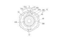
トルクリミット機構50は、螺合筒20の装着部22と操作筒40の基端部との間に形成されている。詳述すると、操作筒40の基端部内周には、全周にわたって係合歯51が形成されている。係合歯51は緩み防止機構30のラチェット歯31に似た形状を有している。
The
螺合筒20の装着部22の端部には、周方向に180°離れた一対のL字形をなすスリット54が形成されている。このスリット54は、装着部22の端面から軸方向に延びる縦部分と、この縦部分の奥端から周方向に延びる横部分とを有している。このスリット54により周方向に延びる第2弾性片52が画成されている。第2弾性片52は周方向寸法が小さいので、弾性係数は緩み防止機構30の弾性片32よりはるかに大きい。
第2弾性片52の先端部外面には第2係合爪53が形成されている。この第2係合爪53は径方向外方向に突出して上記係合歯51と噛み合っている。緩み防止機構30のラチェット歯31は、軸方向において第2弾性片52に隣接している。
A pair of L-shaped
A
上記構成において、雄型アッセンブリ1Bに雌型コネクタ2(図5参照)を近づけ、雄型ルアー部11を雌型ルアー部2cに差し込んだ状態で、操作筒40を締め付け方向Tに回すと、操作筒40のトルクがトルクリミット機構50を介して螺合筒20に伝達される。トルクリミット機構50の第2弾性片52の弾性係数が大きいので、図15Aに示すように、トルクリミット機構50の係合歯51の歯部の傾斜面51aと第2係合爪53の傾斜面53aが当たった状態で、係合歯51と第2係合爪53の噛み合い状態が維持されており、操作筒40と螺合筒20は一緒に回る。
In the above configuration, when the female connector 2 (see FIG. 5) is brought close to the
上記操作筒40と螺合筒20は雄型コネクタ10に対して締め付け方向Tに回わる。緩み防止機構30の抵抗が小さいからである。その結果、雌ねじ21aと係合突起2cとの螺合が進み、雄型ルアー部11と雌型ルアー部2aが押圧力をもって接合する。このようにして、十分なシール性能で雄型ルアー部11と雌型ルアー部2aを接合することができる。
The
さらに操作筒40を回して設定トルクを超えると、図15Bに示すように、第2係合爪53の傾斜面53aが係合歯51の歯部の傾斜面51aを滑り、第2弾性片52の弾性変形を伴って、第2係合爪53が操作筒40の係合歯51の各歯部を乗り越える。このように、操作筒40が螺合筒20に対して空回りし、操作筒40の回転トルクが螺合筒20に伝達されない。その結果、螺合筒20に過剰なトルクが付与されず、雄型ルアー部11と雌型ルアー部2aとの間の押圧力が過剰になるのを回避できるので、雄型ルアー部11や雌型ルアー部2の破損を防止でき、雄型ルアー部11と雌型ルアー部2aが離脱不能な程度に噛み付くのを回避できる。
When the operating
上記のようにしてチューブ5、5’を接続した後、接続の解除が必要になった場合には、操作筒40を螺合緩み方向に回す。すると、操作筒40の係合歯51の歯部の急峻な係止面51bが、螺合筒20の第2係合爪53の急峻な係止面53bに当たり、螺合筒20と雄型コネクタ10が操作筒40と一緒に緩み方向に回る。その結果、雄型ルアー部11と雌型ルアー部2bの接合状態が解除される。
If it is necessary to release the connection after connecting the
図16〜図18は、本発明の第2実施形態に係る医療用接続構造の雄型アッセンブリ1Cを示す。この雄型アッセンブリ1Cにおいて、雄型コネクタ10A、螺合筒20Aおよび緩み防止機構30Aは、第2参考例と実質的に同じである。ただし、螺合筒20Aの螺合部21の外周は第2参考例と異なり突条が形成されておらず円筒面をなしている。螺合部21の先端部外周には環状凸部23が形成されている。
16 to 18 show a
本実施形態の雄型アッセンブリ1Cは、さらに操作筒40とトルクリミット機構50Cとを備えている。操作筒40は螺合筒20Aに軸方向移動不能に装着されており、これら操作筒40の螺合筒20Aとの間には環状空隙45が形成されている。
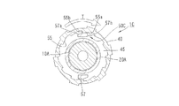
操作筒40の中間部内周には、環状空隙45に臨む係止歯55が全周にわたって形成されている。一方、螺合筒20Aの中間部には、径方向に延びるとともに環状空隙45に臨む環状の支持面26が形成されている。第2弾性片56が、この支持面26から雌ねじ21aの反対側に向かって軸方向に延びており、この第2弾性片56の先端部外面に第2係合爪57が形成されている。この第2係合爪57は径方向外方向に突出して係合歯55に噛み合っている。
The
Locking
トルクリミット機構50Cにおいて、係合歯55の歯部が傾斜面55aと係止面55bを有し、第2係合爪57が傾斜面57aと係止面57bを有することは、第1実施形態におけるトルクリミット機構50と同様である。
In the
雄型アッセンブリ1Cのトルクリミット機構50Cは、第1実施形態のトルクリミット機構50と同様の作用をする。簡単に説明すると、操作筒40のトルクがトルクリミット機構50Cを介して螺合筒20Aに伝達され、操作筒40と螺合筒20Aは雄型コネクタ10Aに対して締め付け方向Tに回わる。緩み防止機構30Aの抵抗が小さいからである。その結果、螺合筒20Aと雌型コネクタ2(図5参照)の螺合が進み、十分なシール性能をもって雄型ルアー部11と雌型ルアー部2aを接合することができる。
The
さらに操作筒40を回して設定トルクを超えると、図18Bに示すように、第2係合爪57の傾斜面57aが係合歯55の各歯部の傾斜面55aを滑り、第2弾性片56の弾性変形を伴って、第2係合爪57が操作筒40の係合歯55の歯部を乗り越える。その結果、操作筒40が螺合筒20Aに対して空回りし、過剰なトルクによる締め付けを回避できる。
接続解除の際には、操作筒40を螺合緩み方向に回す。すると、操作筒40の係合歯55の急峻な係止面55bが螺合筒20Aの第2係合爪57の急峻な係止面57bに当たり、螺合筒20Aと雄型コネクタ10Aが操作筒40と一緒に螺合緩み方向に回る。
When the operating
When releasing the connection, the
図19に示す第3参考例の雄型アッセンブリ1Dでは、雄型コネクタ10Dが、コネクタ本体15と、このコネクタ本体15に回動可能に連結された連結ピース16とを有している。コネクタ本体15は雄型ルアー部11と装着部13を有しており、連結ピース16は連結部12を有している。他は第1参考例と同様である。このような雄型コネクタ10Dを第2参考例および第1、第2実施形態でも採用可能である。
In the
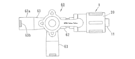
図20、図21に示す第4参考例は、本発明を三方活栓60(活栓)に適用したものである。この三方活栓60は、筒形状をなすボデイ61と、このボデイ61に一体に形成された3つの流通管部62,63,63を有している。1つの流通管部62は、その先端部に第1参考例と同様の雄型アッセンブリ1が装着されている。この雄型アッセンブリ1の雄型コネクタ10は流通管部62と一体をなしている。他の2つの流通管部63,63の先端部には雌型ルアー部63aと係合突起63bが形成されている。
In the fourth reference example shown in FIGS. 20 and 21, the present invention is applied to a three-way stopcock 60 (stopcock). The three-
上記ボデイ61には栓部材65が収容されている。この栓部材65はL字形をなす連通路65aを有し、回動操作により流通管部62,63,63の通路のうち2つを選択的に連通させるようになっている。
三方活栓に第2参考例および第1、第2実施形態の雄型アッセンブリを装着してもよい。
A
The male assembly of the second reference example and the first and second embodiments may be attached to the three-way cock.
本発明は上記実施形態に制約されず、種々の態様が可能である。上述した多数の参考例および実施形態の各々の特徴は、他の実施形態の特徴と組み合わせることも可能である。
本発明は、チューブ、活栓の他、あらゆる医療用構成要素での接続構造に適用することができる。
The present invention is not limited to the above-described embodiments, and various aspects are possible. The features of each of the numerous reference examples and embodiments described above can be combined with the features of other embodiments.
The present invention can be applied to a connection structure in any medical component other than tubes and stopcocks.
本発明は、医療構成要素のための接続構造に適用することができる。 The present invention can be applied to connection structures for medical components.
Claims (6)
雄型アッセンブリが、筒形状の雄型コネクタ(10;10A)と、上記雄型コネクタに回転可能に連結された螺合筒(20;20A)とを有し、
上記雄型コネクタは、先端から基端に向かって順に配置された雄型ルアー部(11)と支持部(13;13A)とを有し、
上記螺合筒は、先端から基端に向かって順に配置された螺合部(21)と装着部(22;22A)とを有し、上記装着部は上記雄型コネクタの上記支持部外周に回転可能に装着され、上記螺合部は内周に雌ねじ(21a)を有するとともに上記雄型ルアー部の径方向外側に配置されており、
上記雌型コネクタは、雌型ルアー部(2a)と、この雌型ルアー部外周に形成された係合突起(2c)を有し、
上記螺合筒の上記雌ねじと上記雌型コネクタの上記係合突起が螺合した状態で、上記螺合筒を締め付け方向に回転することにより、上記雄型ルアー部と上記雌型ルアー部が接合される医療用接続構造において、
さらに、上記螺合筒(20;20A)の外周に装着された操作筒(40)と、上記螺合筒と上記操作筒との間に配置されたトルクリミット機構(50;50C)とを備え、
上記トルクリミット機構は、上記操作筒の締め付け方向の回転トルクを上記螺合筒に伝達し、上記回転トルクが設定トルクを越えた時に、上記操作筒を上記螺合筒に対して空回りさせ、
上記トルクリミット機構は、上記操作筒の内周に全周にわたって形成された係合歯(51;55)と、上記螺合筒に形成された少なくとも1つの弾性片(52;56)と、上記弾性片に形成され径方向外方向に突出して上記係合歯に噛み合う係合爪(53;57)と、を有し、
上記弾性片と上記雄型コネクタの外周との間には空隙が形成され、上記弾性片は、上記操作筒の空回りの際に、径方向内方向に変形することを特徴とする医療用接続構造。 A male assembly (1B; 1C) and a cylindrical female connector (2);
The male assembly has a cylindrical male connector (10; 10A) and a threaded cylinder (20; 20A) rotatably connected to the male connector,
The male connector has a male luer part (11) and a support part (13; 13A) arranged in order from the distal end to the proximal end,
The threaded cylinder has a threaded part (21) and a mounting part (22; 22A) arranged in order from the distal end to the base end, and the mounting part is provided on the outer periphery of the support part of the male connector. It is rotatably mounted, the threaded portion has a female screw (21a) on the inner periphery and is disposed on the radially outer side of the male luer portion,
The female connector has a female luer part (2a) and an engaging protrusion (2c) formed on the outer periphery of the female luer part.
The male luer part and the female luer part are joined by rotating the screwing cylinder in the tightening direction in a state where the female screw of the screwing cylinder and the engaging projection of the female connector are screwed together. In the medical connection structure
Furthermore, an operation cylinder (40) mounted on the outer periphery of the screwing cylinder (20; 20A) and a torque limit mechanism (50; 50C) disposed between the screwing cylinder and the operation cylinder are provided. ,
The torque limit mechanism transmits rotational torque in the tightening direction of the operation cylinder to the screwing cylinder, and when the rotation torque exceeds a set torque, the operation cylinder is idled with respect to the screwing cylinder,
The torque limit mechanism includes an engagement tooth (51; 55) formed on the inner periphery of the operation cylinder over the entire periphery, at least one elastic piece (52; 56) formed on the threaded cylinder, An engagement claw (53; 57) formed on the elastic piece and projecting radially outward to mesh with the engagement tooth,
A medical connection structure characterized in that a gap is formed between the elastic piece and the outer periphery of the male connector, and the elastic piece is deformed radially inward when the operation cylinder is idle. .
雄型アッセンブリが、筒形状の雄型コネクタ(10)と、上記雄型コネクタに回転可能に連結された螺合筒(20)とを有し、
上記雄型コネクタは、先端から基端に向かって順に配置された雄型ルアー部(11)と支持部(13)とを有し、
上記螺合筒は、先端から基端に向かって順に配置された螺合部(21)と装着部(22)とを有し、上記装着部は上記雄型コネクタの上記支持部外周に回転可能に装着され、上記螺合部は内周に雌ねじ(21a)を有するとともに上記雄型ルアー部の径方向外側に配置されており、
上記雌型コネクタは、雌型ルアー部(2a)と、この雌型ルアー部外周に形成された係合突起(2c)を有し、
上記螺合筒の上記雌ねじと上記雌型コネクタの上記係合突起が螺合した状態で、上記螺合筒を締め付け方向に回転することにより、上記雄型ルアー部と上記雌型ルアー部が接合される医療用接続構造において、
さらに、上記螺合筒(20)の外周に装着された操作筒(40)と、上記螺合筒と上記操作筒との間に配置されたトルクリミット機構(50)とを備え、
上記トルクリミット機構は、上記操作筒の締め付け方向の回転トルクを上記螺合筒に伝達し、上記回転トルクが設定トルクを越えた時に、上記操作筒を上記螺合筒に対して空回りさせ、
上記トルクリミット機構は、上記操作筒の内周に全周にわたって形成された係合歯(51)と、上記螺合筒に形成された少なくとも1つの弾性片(52)と、上記弾性片に形成され径方向外方向に突出して上記係合歯に噛み合う係合爪(53)と、を有し、
上記弾性片は、上記操作筒の空回りの際に、径方向内方向に変形し、
上記螺合筒の端部にはスリット(54)が形成されており、上記スリットは、上記螺合筒の端から軸方向に延びる縦部分と、この縦部分の奥端から周方向に延びる横部分と、を有してL字形をなし、上記弾性片がこのスリットにより画成されていることを特徴とする医療用接続構造。 A male assembly (1B) and a tubular female connector (2);
The male assembly has a cylindrical male connector (10) and a threaded cylinder (20) rotatably connected to the male connector,
The male connector has a male luer part (11) and a support part (13) arranged in order from the distal end to the proximal end,
The threaded cylinder has a threaded part (21) and a mounting part (22) arranged in order from the distal end to the base end, and the mounting part is rotatable on the outer periphery of the support part of the male connector. The threaded portion has a female screw (21a) on the inner periphery and is disposed on the radially outer side of the male luer portion,
The female connector has a female luer part (2a) and an engaging protrusion (2c) formed on the outer periphery of the female luer part.
The male luer part and the female luer part are joined by rotating the screwing cylinder in the tightening direction in a state where the female screw of the screwing cylinder and the engaging projection of the female connector are screwed together. In the medical connection structure
And an operating cylinder (40) mounted on the outer periphery of the screwing cylinder (20), and a torque limit mechanism (50) disposed between the screwing cylinder and the operating cylinder.
The torque limit mechanism transmits rotational torque in the tightening direction of the operation cylinder to the screwing cylinder, and when the rotation torque exceeds a set torque, the operation cylinder is idled with respect to the screwing cylinder,
The torque limit mechanism is formed on the engagement piece (51) formed on the inner circumference of the operation cylinder over the entire circumference, at least one elastic piece (52) formed on the threaded cylinder, and the elastic piece. And an engaging claw (53) that protrudes radially outward and meshes with the engaging tooth,
The elastic piece is deformed radially inward when the operation cylinder is idle,
A slit (54) is formed at the end of the threaded tube , and the slit has a vertical portion extending in the axial direction from the end of the threaded tube , and a horizontal portion extending in the circumferential direction from the back end of the vertical portion. A medical connection structure, wherein the elastic piece is defined by the slit.
雄型アッセンブリが、筒形状の雄型コネクタ(10A)と、上記雄型コネクタに回転可能に連結された螺合筒(20A)とを有し、
上記雄型コネクタは、先端から基端に向かって順に配置された雄型ルアー部(11)と支持部(13A)とを有し、
上記螺合筒は、先端から基端に向かって順に配置された螺合部(21)と装着部(22A)とを有し、上記装着部は上記雄型コネクタの上記支持部外周に回転可能に装着され、上記螺合部は内周に雌ねじ(21a)を有するとともに上記雄型ルアー部の径方向外側に配置されており、
上記雌型コネクタは、雌型ルアー部(2a)と、この雌型ルアー部外周に形成された係合突起(2c)を有し、
上記螺合筒の上記雌ねじと上記雌型コネクタの上記係合突起が螺合した状態で、上記螺合筒を締め付け方向に回転することにより、上記雄型ルアー部と上記雌型ルアー部が接合される医療用接続構造において、
さらに、上記螺合筒(20A)の外周に装着された操作筒(40)と、上記螺合筒と上記操作筒との間に配置されたトルクリミット機構(50C)とを備え、
上記トルクリミット機構は、上記操作筒の締め付け方向の回転トルクを上記螺合筒に伝達し、上記回転トルクが設定トルクを越えた時に、上記操作筒を上記螺合筒に対して空回りさせ、
上記トルクリミット機構は、上記操作筒の内周に全周にわたって形成された係合歯(55)と、上記螺合筒に形成された少なくとも1つの弾性片(56)と、上記弾性片に形成され径方向外方向に突出して上記係合歯に噛み合う係合爪(57)と、を有し、
上記弾性片は、上記操作筒の空回りの際に、径方向内方向に変形し、
上記螺合筒と上記操作筒との間には環状空隙(45)が形成されており、上記係合歯が上記操作筒の内周に形成されて上記環状空隙に臨み、
上記螺合筒に上記弾性片が形成されて上記環状空隙に配置されていることを特徴とする医療用接続構造。 A male assembly (1C) and a tubular female connector (2);
The male assembly has a cylindrical male connector (10A) and a threaded cylinder (20A) rotatably connected to the male connector,
The male connector has a male luer part (11) and a support part (13A) arranged in order from the distal end to the proximal end,
The threaded cylinder has a threaded part (21) and a mounting part (22A) arranged in order from the distal end to the base end, and the mounting part is rotatable on the outer periphery of the support part of the male connector. The screwing portion has a female screw (21a) on the inner periphery and is disposed on the radially outer side of the male luer portion,
The female connector has a female luer part (2a) and an engaging protrusion (2c) formed on the outer periphery of the female luer part.
The male luer part and the female luer part are joined by rotating the screwing cylinder in the tightening direction in a state where the female screw of the screwing cylinder and the engagement protrusion of the female connector are screwed together. In the medical connection structure
Furthermore, an operation cylinder (40) mounted on the outer periphery of the screwing cylinder (20A), and a torque limit mechanism (50C) disposed between the screwing cylinder and the operation cylinder,
The torque limit mechanism transmits rotational torque in the tightening direction of the operation cylinder to the screwing cylinder, and when the rotation torque exceeds a set torque, the operation cylinder is idled with respect to the screwing cylinder,
The torque limit mechanism is formed on the engagement piece (55) formed on the inner circumference of the operation cylinder over the entire circumference, at least one elastic piece (56) formed on the threaded cylinder, and the elastic piece. An engaging claw (57) projecting radially outward and meshing with the engaging tooth,
The elastic piece is deformed radially inward when the operating cylinder is idle,
An annular space (45) is formed between the threaded tube and the operation tube, and the engagement teeth are formed on the inner periphery of the operation tube and face the annular space,
Medical connecting structure, characterized in that is the elastic piece formed on the screwed sleeve are arranged in the annular space.
雄型アッセンブリが、筒形状の雄型コネクタ(10;10A)と、上記雄型コネクタに回転可能に連結された螺合筒(20;20A)とを有し、
上記雄型コネクタは、先端から基端に向かって順に配置された雄型ルアー部(11)と支持部(13;13A)とを有し、
上記螺合筒は、先端から基端に向かって順に配置された螺合部(21)と装着部(22;22A)とを有し、上記装着部は上記雄型コネクタの上記支持部外周に回転可能に装着され、上記螺合部は内周に雌ねじ(21a)を有するとともに上記雄型ルアー部の径方向外側に配置されており、
上記雌型コネクタは、雌型ルアー部(2a)と、この雌型ルアー部外周に形成された係合突起(2c)を有し、
上記螺合筒の上記雌ねじと上記雌型コネクタの上記係合突起が螺合した状態で、上記螺合筒を締め付け方向に回転することにより、上記雄型ルアー部と上記雌型ルアー部が接合される医療用接続構造において、
さらに、上記螺合筒(20;20A)の外周に装着された操作筒(40)と、上記螺合筒と上記操作筒との間に配置されたトルクリミット機構(50;50C)とを備え、
上記トルクリミット機構は、上記操作筒の締め付け方向の回転トルクを上記螺合筒に伝達し、上記回転トルクが設定トルクを越えた時に、上記操作筒を上記螺合筒に対して空回りさせ、
上記トルクリミット機構は、上記操作筒の内周に全周にわたって形成された係合歯(51;55)と、上記螺合筒に形成された少なくとも1つの弾性片(52;56)と、上記弾性片に形成され径方向外方向に突出して上記係合歯に噛み合う係合爪(53;57)と、を有し、
上記弾性片は、上記操作筒の空回りの際に、径方向内方向に変形し、
さらに、上記雄型ルアー部と上記雌型ルアー部の接合状態において上記雄型コネクタに対する上記螺合筒の緩み方向の回動を禁じる緩み防止機構(30;30A)が、上記雄型コネクタの上記支持部と上記螺合筒の装着部との間に配置され、
上記緩み防止機構は、上記雄型コネクタの上記支持部と上記螺合筒の上記装着部の一方の全周にわたって形成されたラチェット歯と、上記支持部と上記装着部の他方に形成された少なくとも1つの他の弾性片(32;36)と、当該他の弾性片に形成されて上記ラチェット歯に噛み合う他の係合爪(33;38)と、を有し、
上記トルクリミット機構の上記弾性片の弾性係数が上記緩み防止機構の上記他の弾性片より大きいことを特徴とする医療用接続構造。 A male assembly (1B; 1C) and a cylindrical female connector (2);
The male assembly has a cylindrical male connector (10; 10A) and a threaded cylinder (20; 20A) rotatably connected to the male connector,
The male connector has a male luer part (11) and a support part (13; 13A) arranged in order from the distal end to the proximal end,
The threaded cylinder has a threaded part (21) and a mounting part (22; 22A) arranged in order from the distal end to the base end, and the mounting part is provided on the outer periphery of the support part of the male connector. It is rotatably mounted, the threaded portion has a female screw (21a) on the inner periphery and is disposed on the radially outer side of the male luer portion,
The female connector has a female luer part (2a) and an engaging protrusion (2c) formed on the outer periphery of the female luer part.
The male luer part and the female luer part are joined by rotating the screwing cylinder in the tightening direction in a state where the female screw of the screwing cylinder and the engaging projection of the female connector are screwed together. In the medical connection structure
Furthermore, an operation cylinder (40) mounted on the outer periphery of the screwing cylinder (20; 20A) and a torque limit mechanism (50; 50C) disposed between the screwing cylinder and the operation cylinder are provided. ,
The torque limit mechanism transmits rotational torque in the tightening direction of the operation cylinder to the screwing cylinder, and when the rotation torque exceeds a set torque, the operation cylinder is idled with respect to the screwing cylinder,
The torque limit mechanism includes an engagement tooth (51; 55) formed on the inner periphery of the operation cylinder over the entire periphery, at least one elastic piece (52; 56) formed on the threaded cylinder, An engagement claw (53; 57) formed on the elastic piece and projecting radially outward to mesh with the engagement tooth,
The elastic piece is deformed radially inward when the operation cylinder is idle,
Furthermore, a loosening prevention mechanism (30; 30A) that inhibits rotation of the screwed tube relative to the male connector in the loosened state in the joined state of the male luer part and the female luer part includes the male connector. It is arranged between the support part and the mounting part of the screw cylinder,
The loosening prevention mechanism includes ratchet teeth formed over the entire circumference of one of the support portion of the male connector and the mounting portion of the screw-in cylinder, and at least formed on the other of the support portion and the mounting portion. One other elastic piece (32; 36) and another engagement claw (33; 38) formed on the other elastic piece and meshing with the ratchet teeth,
A medical connection structure, wherein an elastic coefficient of the elastic piece of the torque limit mechanism is larger than that of the other elastic piece of the loosening prevention mechanism.
上記緩み防止機構の上記他の弾性片が上記雄型コネクタの支持部に形成され、上記他の係合爪が径方向外方向に突出して上記ラチェット歯に噛み合っていることを特徴とする請求項5に記載の医療用接続構造。 The ratchet teeth of the loosening prevention mechanism are formed on the inner periphery of the mounting portion of the screw-in cylinder, and are adjacent to the elastic piece of the torque limit mechanism in the axial direction.
The said other elastic piece of the said loosening prevention mechanism is formed in the support part of the said male connector, The said other engagement nail | claw protrudes radially outward and is meshing | engaged with the said ratchet teeth. 5. The medical connection structure according to 5.
Priority Applications (1)
| Application Number | Priority Date | Filing Date | Title |
|---|---|---|---|
| JP2018168614A JP6599528B2 (en) | 2018-09-10 | 2018-09-10 | Medical connection structure |
Applications Claiming Priority (1)
| Application Number | Priority Date | Filing Date | Title |
|---|---|---|---|
| JP2018168614A JP6599528B2 (en) | 2018-09-10 | 2018-09-10 | Medical connection structure |
Related Parent Applications (1)
| Application Number | Title | Priority Date | Filing Date |
|---|---|---|---|
| JP2017555728A Division JP6462900B1 (en) | 2017-04-12 | 2017-04-12 | Medical connection structure |
Publications (3)
| Publication Number | Publication Date |
|---|---|
| JP2019011864A JP2019011864A (en) | 2019-01-24 |
| JP2019011864A5 JP2019011864A5 (en) | 2019-09-12 |
| JP6599528B2 true JP6599528B2 (en) | 2019-10-30 |
Family
ID=65226248
Family Applications (1)
| Application Number | Title | Priority Date | Filing Date |
|---|---|---|---|
| JP2018168614A Active JP6599528B2 (en) | 2018-09-10 | 2018-09-10 | Medical connection structure |
Country Status (1)
| Country | Link |
|---|---|
| JP (1) | JP6599528B2 (en) |
Family Cites Families (2)
| Publication number | Priority date | Publication date | Assignee | Title |
|---|---|---|---|---|
| US7998134B2 (en) * | 2007-05-16 | 2011-08-16 | Icu Medical, Inc. | Medical connector |
| US10183158B2 (en) * | 2015-04-02 | 2019-01-22 | Koyo Sangyo Co., Ltd. | Connecting structure for medical use |
-
2018
- 2018-09-10 JP JP2018168614A patent/JP6599528B2/en active Active
Also Published As
| Publication number | Publication date |
|---|---|
| JP2019011864A (en) | 2019-01-24 |
Similar Documents
| Publication | Publication Date | Title |
|---|---|---|
| JP6462900B1 (en) | Medical connection structure | |
| JP7020724B2 (en) | Male medical connection device | |
| JP2961532B1 (en) | Tightening regulator made of synthetic resin for fastening members for joints | |
| JP6468678B2 (en) | Medical connection structure | |
| JP2001227691A (en) | Connector device | |
| JP2004092903A (en) | Pipe connector | |
| JP6599528B2 (en) | Medical connection structure | |
| JPH04296291A (en) | Pipe joint | |
| JP2002295756A (en) | Simplified swivel hose joint | |
| JP2008256012A (en) | Joint for synthetic resin fluid pipe | |
| JP6176857B2 (en) | Lock type luer taper connector and male and female connectors of the lock type luer taper connector | |
| JP4066397B2 (en) | Tube connection method | |
| JP4254987B2 (en) | Hose fittings | |
| JP3151344U (en) | Medical connector | |
| JP3019906U (en) | Hose connection device | |
| JP4810267B2 (en) | Pipe fitting | |
| JP2004100720A (en) | Pipe joint | |
| JP3778701B2 (en) | Tube connection structure | |
| JP2023071573A (en) | Medical connection device | |
| JP2000249273A (en) | Connecting structure of bellows flexible hose | |
| JP2920630B1 (en) | Pipe fittings | |
| JP2015143565A (en) | Pipe joint | |
| JP2001099370A (en) | Simplified swivel hose joint | |
| JP2010043705A (en) | Joint for flexible tube | |
| JP2004060820A (en) | Mechanical pipe joint |
Legal Events
| Date | Code | Title | Description |
|---|---|---|---|
| A621 | Written request for application examination |
Free format text: JAPANESE INTERMEDIATE CODE: A621 Effective date: 20180910 |
|
| A521 | Written amendment |
Free format text: JAPANESE INTERMEDIATE CODE: A523 Effective date: 20190730 |
|
| A977 | Report on retrieval |
Free format text: JAPANESE INTERMEDIATE CODE: A971007 Effective date: 20190814 |
|
| A131 | Notification of reasons for refusal |
Free format text: JAPANESE INTERMEDIATE CODE: A131 Effective date: 20190827 |
|
| A521 | Written amendment |
Free format text: JAPANESE INTERMEDIATE CODE: A523 Effective date: 20190913 |
|
| TRDD | Decision of grant or rejection written | ||
| A01 | Written decision to grant a patent or to grant a registration (utility model) |
Free format text: JAPANESE INTERMEDIATE CODE: A01 Effective date: 20191001 |
|
| A61 | First payment of annual fees (during grant procedure) |
Free format text: JAPANESE INTERMEDIATE CODE: A61 Effective date: 20191002 |
|
| R150 | Certificate of patent or registration of utility model |
Ref document number: 6599528 Country of ref document: JP Free format text: JAPANESE INTERMEDIATE CODE: R150 |
|
| R250 | Receipt of annual fees |
Free format text: JAPANESE INTERMEDIATE CODE: R250 |