JP6599261B2 - Security service support system and security device - Google Patents
Security service support system and security device Download PDFInfo
- Publication number
- JP6599261B2 JP6599261B2 JP2016023462A JP2016023462A JP6599261B2 JP 6599261 B2 JP6599261 B2 JP 6599261B2 JP 2016023462 A JP2016023462 A JP 2016023462A JP 2016023462 A JP2016023462 A JP 2016023462A JP 6599261 B2 JP6599261 B2 JP 6599261B2
- Authority
- JP
- Japan
- Prior art keywords
- abnormality
- information
- security
- detected
- monitoring area
- Prior art date
- Legal status (The legal status is an assumption and is not a legal conclusion. Google has not performed a legal analysis and makes no representation as to the accuracy of the status listed.)
- Active
Links
Images


Description
本発明は、監視区域の異常に対処する利用者に異常についての情報を送信する機能を備えた警備業務支援システムに関する。 The present invention relates to a security service support system having a function of transmitting information about an abnormality to a user who deals with an abnormality in a monitored area.
従来、警備システムに関して、異常が検知された監視区域のセンサ検知状態などを、警備員(対処員)が携帯端末から確認できるようにして、警備員が発報場所に向かっている間にもある程度現場の状況が分かるようにしたものが知られている(例えば、特許文献1参照)。警備員が対処する前に原因などの情報を把握できるようにすることで、現場での作業の効率化が可能になる。 Conventionally, with regard to the security system, it is possible for the security guard (handling person) to check the sensor detection status of the monitoring area where the abnormality is detected from the mobile terminal, and to some extent while the security guard is heading to the place of alert The thing which made the situation of the field understood is known (for example, refer to patent documents 1). By making it possible for the security guard to grasp the cause and other information before taking action, it is possible to increase the efficiency of work on site.
しかしながら、従来の警備業務支援システムにおいては、監視区域の異常に対処する対処員に異常についての情報を送信するタイミングについて特に考慮されていない。一般に、異常に対処する対処員が現地に到着するまでは、検知した異常についての詳細な情報を伝えることは、思い込みを排除する上で好ましくない。例えば、対処員が早い段階で詳細な情報を得ることにより、異常の場所、程度、確度について思い込みを抱くと、侵入者などの緊急の脅威があり得る状況で油断や緊張感低下を招くおそれがある。 However, in the conventional security service support system, no particular consideration is given to the timing at which information about the abnormality is transmitted to the coping person who deals with the abnormality in the monitored area. In general, it is not preferable to convey detailed information about a detected abnormality until a coping person who deals with the abnormality arrives at the site, in order to eliminate the assumption. For example, if the counselor gets detailed information at an early stage and has a belief about the location, degree, and accuracy of the anomaly, there is a risk of inadvertent alertness and reduced tension in situations where there may be an emergency threat such as an intruder. is there.
本発明は、上記の課題に鑑みてなされたもので、監視区域の異常に対処する利用者に、その異常についての情報を適切なタイミングで送信することのできる警備業務支援システムを提供することを目的とする。 The present invention has been made in view of the above problems, and provides a security service support system capable of transmitting information about an abnormality at an appropriate timing to a user who copes with an abnormality in a monitored area. Objective.
本発明の警備業務支援システムは、監視区域に設置される警備装置と、前記警備装置から信号を受信する遠隔のセンタ装置とを備える警備業務支援システムであって、前記警備装置は、監視区域に設置された検知器から、異常を検知したことを示す検知信号を受信する検知信号受信部と、異常を検知した前記検知器の識別情報を含む異常信号を、前記センタ装置に送信する異常信号送信部と、を備え、前記センタ装置は、前記警備装置から送信された前記異常信号を受信する異常信号受信部と、前記監視区域の警備を行う利用者の携帯端末から送信された、当該利用者が当該監視区域に所在しているか否かを示す状態情報を受信する状態情報受信部と、前記検知器の設置位置を前記検知器の識別情報に関連付けて設置位置情報として記憶する記憶部と、前記異常信号と前記設置位置情報に基づいて、異常を検知した前記検知器の設置位置を特定する位置特定部と、前記状態情報に基づいて、前記利用者が前記監視区域に所在しているか否かを判断する所在判断部と、前記利用者が監視区域に所在していると判断される場合には、異常を検知した前記検知器の設置位置を前記携帯端末へ送信することを許可し、前記利用者が前記監視区域に所在していないと判断される場合には、異常を検知した前記検知器の設置位置を前記携帯端末へ送信することを禁止する送信制御部と、を備えている。 The security service support system of the present invention is a security service support system comprising a security device installed in a monitoring area and a remote center device that receives a signal from the security device, and the security device is in the monitoring area. A detection signal receiving unit that receives a detection signal indicating that an abnormality has been detected from an installed detector, and an abnormality signal transmission that transmits an abnormality signal including identification information of the detector that has detected the abnormality to the center device And the center device receives the abnormal signal transmitted from the security device and the user transmitted from the mobile terminal of the user who performs security in the monitored area. A status information receiving unit for receiving status information indicating whether or not the monitoring area is located, and storing the installation position of the detector as installation position information in association with the identification information of the detector A storage unit, a position specifying unit that specifies an installation position of the detector that has detected an abnormality based on the abnormality signal and the installation position information, and the user is located in the monitoring area based on the status information. If it is determined that the user is located in the monitoring area, and the location determination unit that determines whether or not the user is located, the installation position of the detector that has detected an abnormality is transmitted to the portable terminal. And when it is determined that the user is not located in the monitoring area, a transmission control unit that prohibits transmission of the installation position of the detector that has detected an abnormality to the mobile terminal; It has.
この構成により、利用者が監視区域に所在している場合には、異常を検知した検知器の設置位置の情報が利用者の携帯端末へ送信される。一方、利用者が監視区域に所在していない場合には、異常を検知した検知器の設置位置の情報が利用者の携帯端末へ送信されない。このようにして、携帯端末の利用者の状態(監視区域に所在しているか否か)に応じて、異常を検知した検知器の設置位置の情報を携帯端末に送信するか否かを決定することができる。本発明では、利用者が監視区域に所在していることを条件に、異常を検知した検知器の設置位置の情報が利用者の携帯端末に送信される。これにより、利用者の状態(監視区域に所在しているか否か)に応じた適切なタイミングで情報送信が可能になる。 With this configuration, when the user is located in the monitoring area, information on the installation position of the detector that has detected the abnormality is transmitted to the user's mobile terminal. On the other hand, when the user is not located in the monitoring area, the information on the installation position of the detector that detected the abnormality is not transmitted to the user's mobile terminal. In this way, it is determined whether or not to transmit information on the installation position of the detector that has detected the abnormality to the mobile terminal according to the state of the user of the mobile terminal (whether or not it is located in the monitoring area). be able to. In the present invention, on the condition that the user is located in the monitoring area, information on the installation position of the detector that has detected the abnormality is transmitted to the user's portable terminal. Thereby, it becomes possible to transmit information at an appropriate timing according to the state of the user (whether or not the user is located in the monitoring area).
また、本発明の警備業務支援システムでは、前記警備装置は、さらに、複数の警備モードが設定可能なモード設定部を備え、前記センタ装置の送信制御部は、前記利用者が監視区域に所在していると判断される場合には、前記警備装置の警備モードが前回変更されてから現在までの間に異常を検知した前記検知器の設置位置を前記携帯端末へ送信し、前記携帯端末の表示部に、前記異常を検知した前記検知器の設置位置を検知順に表示させてもよい。 In the security service support system of the present invention, the security device further includes a mode setting unit capable of setting a plurality of security modes, and the transmission control unit of the center device is located in a monitoring area by the user. If it is determined that the security mode of the security device is changed from the last time the security mode of the security device is changed to the present, the installation position of the detector that has detected an abnormality is transmitted to the mobile device, and the display of the mobile device is displayed. The installation position of the detector that has detected the abnormality may be displayed in the order of detection.
この構成により、警備装置の警備モードが前回変更されてから現在までの間に異常を検知した検知器の設置位置が、携帯端末へ送信される。そして、携帯端末の表示部に、その異常を検知した検知器の設置位置が検知順に表示される。このようにして、より必要度の高い情報(最近異常を検知した検知器の設置位置の情報)が携帯端末へ送信され、携帯端末の表示部に分かりやすく(異常を検知した順に)表示される。これにより、利用者は異常の発生(異常の検知)の流れを容易に把握することができる。 With this configuration, the installation position of the detector that has detected an abnormality between the last time the security mode of the security device was changed and the current time is transmitted to the mobile terminal. And the installation position of the detector which detected the abnormality is displayed on the display part of a portable terminal in order of detection. In this way, information with higher necessity (information on the installation position of the detector that has recently detected an abnormality) is transmitted to the mobile terminal and displayed on the display unit of the mobile terminal in an easy-to-understand order (in the order in which the abnormality was detected). . Thereby, the user can easily grasp the flow of occurrence of abnormality (detection of abnormality).
また、本発明の警備業務支援システムでは、前記センタ装置の記憶部は、さらに、前記検知器が異常を検知した時刻を示す時刻情報を、当該異常を検知した前記検知器の識別情報に関連付けて記憶するとともに、前記監視区域の図面情報を記憶し、前記センタ装置は、さらに、所定の時点において前記異常を検知した前記検知器の設置位置を前記監視区域の図面情報に識別可能に重畳した検知位置画像を生成し、複数の時点の前記検知位置画像を前記時刻情報に基づいて時系列に並べた動画情報を生成する動画情報生成部を備え、前記センタ装置の送信制御部は、前記利用者が監視区域に所在していると判断される場合には、前記動画情報生成部により生成された前記動画情報を前記異常を検知した検知器の設置位置として前記携帯端末に送信してもよい。 In the security service support system of the present invention, the storage unit of the center device further associates time information indicating a time at which the detector detects an abnormality with identification information of the detector at which the abnormality is detected. In addition to storing the drawing information of the monitoring area, the center device further detects the superimposing position of the detector that has detected the abnormality at a predetermined time point so as to be identifiable on the drawing information of the monitoring area. A moving image information generating unit configured to generate a position image and generate moving image information in which the detected position images at a plurality of time points are arranged in time series based on the time information, and the transmission control unit of the center device includes the user Is determined to be located in the monitoring area, the moving image information generated by the moving image information generation unit is sent to the portable terminal as the installation position of the detector that has detected the abnormality. It may be.
この構成により、センタ装置で、異常を検知した検知器の設置位置が監視区域の図面情報に識別可能に重畳された検知位置画像を時系列に並べた動画情報が生成され、利用者が監視区域に所在している場合に、その動画情報が利用者の携帯端末へ送信される。この動画情報により、利用者は異常の発生(異常の検知)の流れを容易に把握することができる。 With this configuration, the center device generates moving image information in which the detection position images in which the detection positions of the detectors that have detected an abnormality are superimposed on the drawing information of the monitoring area so as to be identifiable are arranged in time series. If it is located at the location, the video information is transmitted to the user's mobile terminal. With this moving image information, the user can easily grasp the flow of occurrence of abnormality (detection of abnormality).
また、本発明の警備業務支援システムでは、前記動画情報生成部は、前記動画情報を、最新の検知位置画像を最終フレームとした動画によるストリーミング映像として生成し、前記送信制御部は、前記携帯端末から過去の時点の検知位置画像について再生要求を受け付けると、現時点を基準とした相対時間情報とともに前記再生要求のあった過去の時点の検知位置画像を開始フレームとした前記ストリーミング映像を前記携帯端末に配信してもよい。 In the security service support system of the present invention, the moving image information generation unit generates the moving image information as a streaming image by a moving image with the latest detected position image as a final frame, and the transmission control unit includes the mobile terminal. When a playback request is received for a detected position image at a past time point, the streaming video with the detected position image at the past time point at which the playback request has been made as a start frame is transmitted to the portable terminal together with relative time information based on the current time point. You may distribute.
この構成により、センタ装置では、最新の検知位置画像を最終フレームとしたストリーミング映像が生成される。そして、携帯端末から過去の時点の検知位置画像について再生要求を受け付けると、現時点を基準とした相対時間情報とともに、携帯端末から再生要求のあった過去の時点の検知位置画像を開始フレームとしたストリーミング映像が携帯端末に配信される。このストリーミング映像の配信(ストリーミング配信)により、利用者は異常の発生(異常の検知)の流れを容易に把握することができる。 With this configuration, the center device generates a streaming video with the latest detected position image as the final frame. When a playback request is received for a detected position image at a past time from the mobile terminal, streaming using the detected position image at the past time when the playback request was received from the mobile terminal as well as relative time information based on the current time The video is distributed to the mobile terminal. With this streaming video distribution (streaming distribution), the user can easily grasp the flow of occurrence of abnormality (detection of abnormality).
本発明の警備装置は、監視区域に設置される警備装置であって、監視区域に設置された検知器から、異常を検知したことを示す検知信号を受信する検知信号受信部と、前記監視区域の警備を行う利用者が当該監視区域に所在しているか否かを示す状態情報を受信する状態情報受信部と、前記検知器の設置位置を前記検知器の識別情報に関連付けて設置位置情報として記憶する記憶部と、前記異常信号と前記設置位置情報に基づいて、異常を検知した前記検知器の設置位置を特定する位置特定部と、前記状態情報に基づいて、前記利用者が前記監視区域に所在しているか否かを判断する所在判断部と、前記利用者が監視区域に所在していると判断される場合には、異常を検知した前記検知器の設置位置を前記携帯端末へ送信することを許可し、前記利用者が前記監視区域に所在していないと判断される場合には、異常を検知した前記検知器の設置位置を前記携帯端末へ送信することを禁止する送信制御部と、を備えている。 A security device according to the present invention is a security device installed in a monitoring area, a detection signal receiving unit that receives a detection signal indicating that an abnormality has been detected from a detector installed in the monitoring area, and the monitoring area A status information receiving unit that receives status information indicating whether or not a user performing security is located in the monitoring area, and setting the installation position of the detector as identification information of the detector as installation position information A storage unit for storing; a position specifying unit for specifying an installation position of the detector that has detected an abnormality based on the abnormality signal and the installation position information; and If it is determined that the user is located in the monitoring area, the installation position of the detector that has detected an abnormality is transmitted to the portable terminal. Allowed to A transmission control unit that prohibits transmission of the installation position of the detector that has detected an abnormality to the portable terminal when it is determined that the user is not located in the monitoring area; .
この警備装置によっても、上記のシステムと同様に、利用者が監視区域に所在している場合には、異常を検知した検知器の設置位置の情報が利用者の携帯端末へ送信される。一方、利用者が監視区域に所在していない場合には、異常を検知した検知器の設置位置の情報が利用者の携帯端末へ送信されない。このようにして、携帯端末の利用者の状態(監視区域に所在しているか否か)に応じて、異常を検知した検知器の設置位置の情報を携帯端末に送信するか否かを決定することができる。本発明では、利用者が監視区域に所在していることを条件に、異常を検知した検知器の設置位置の情報が利用者の携帯端末に送信される。これにより、利用者の状態(監視区域に所在しているか否か)に応じた適切なタイミングで情報送信が可能になる。 Similarly to the above-described system, this security device transmits information on the installation position of the detector that has detected an abnormality to the user's mobile terminal when the user is located in the monitoring area. On the other hand, when the user is not located in the monitoring area, the information on the installation position of the detector that detected the abnormality is not transmitted to the user's mobile terminal. In this way, it is determined whether or not to transmit information on the installation position of the detector that has detected the abnormality to the mobile terminal according to the state of the user of the mobile terminal (whether or not it is located in the monitoring area). be able to. In the present invention, on the condition that the user is located in the monitoring area, information on the installation position of the detector that has detected the abnormality is transmitted to the user's portable terminal. Thereby, it becomes possible to transmit information at an appropriate timing according to the state of the user (whether or not the user is located in the monitoring area).
本発明によれば、監視区域の異常に対処する利用者に、その異常についての情報を適切なタイミングで送信することができる。 ADVANTAGE OF THE INVENTION According to this invention, the information about the abnormality can be transmitted to the user who copes with the abnormality of a monitoring area at an appropriate timing.
以下、本発明の実施の形態の警備業務支援システムについて、図面を用いて説明する。本実施の形態では、施設や邸宅の警備等に用いられる警備業務支援システムの場合を例示する。 Hereinafter, a security service support system according to an embodiment of the present invention will be described with reference to the drawings. In the present embodiment, a case of a security service support system used for security of facilities and residences is illustrated.
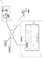
本発明の実施の形態の警備業務支援システムの構成を、図面を参照して説明する。図1は、本実施の形態の警備業務支援システムの概略構成を示す図である。図1に示すように、警備業務支援システム1は、施設や邸宅などの監視区域に設置される警備装置2と、遠隔の監視センタに設置されるセンタ装置3を備えている。警備装置2は、ネットワーク4(公衆回線網やインターネット網)を介してセンタ装置3と通信する。また、監視区域で発生した異常に対処する対処員(監視区域の警備を行う利用者)は、携帯端末5を所持している。センタ装置3は、ネットワーク4および基地局6を介して携帯端末5と無線通信する。
A configuration of a security service support system according to an embodiment of the present invention will be described with reference to the drawings. FIG. 1 is a diagram showing a schematic configuration of a security service support system according to the present embodiment. As shown in FIG. 1, a security
また、図1に示すように、監視区域の各所には、監視区域における異常を検知するための防犯センサ7が設置されている。防犯センサ7は、警備装置2に接続されている。防犯センサ7には、監視区域の建物内に設置される屋内設置のセンサと、庭などの監視区域の建物外に設置される屋外設置のセンサとが含まれる。屋内設置のセンサとしては、例えば、窓や扉が開いたことを検知するセンサや、室内の移動体を検知するセンサなどが含まれる。また、屋外設置のセンサとしては、例えば、移動体を検知するセンサなどが含まれる。防犯センサ7は、検知対象の事象となる異常を検知すると自己の識別情報を含む検知信号を警備装置2に送信する。防犯センサ7と警備装置2との間の通信は、有線または無線で行われる。
As shown in FIG. 1,
警備装置2から監視センタのセンタ装置3へ異常発生の通報が行われると、センタ装置3にてこの情報が管制員などに対して報知される。そして、監視センタから対処員に対して当該監視区域に急行して異常に対処する旨の「対処」の指示が送られる。対処員は、監視センタとの連絡や連携をとりながら、施設や邸宅で発生した異常(不審者の侵入、火災の発生など)に対処する。
When the
ここで、図2および図3を参照しながら、警備装置2、センタ装置3、携帯端末5の構成について詳しく説明する。まず、図2を参照して警備装置2の構成について説明する。図2に示すように、警備装置2は、操作部20、通信部21、表示部22、入出力部23、記憶部24、制御部25を備えている。
Here, the configuration of the
操作部20は、警備装置2の動作モード(警備セットモードや警備解除モードなど。後述する)を設定するために操作される。また、操作部20は、対処員や対処員以外の監視区域の利用者である一般利用者(以降、対処員と一般利用者とをあわせて「利用者」ということがある)の認証情報を読み取る機能を備えている。認証情報を読み込ませて利用者を照合すると、操作入力が許容される。この操作部20は、タッチパネルなどで構成してもよい。
The
通信部21は、センタ装置3と通信するための機能を備えている。通信部21は、警備装置2とセンタ装置3を接続するための通信インターフェースである。上述のように、警備装置2とセンタ装置3は、ネットワーク4としての公衆回線網やインターネット網を介して接続される。
The
表示部22は、利用者に対して操作のガイドなどを出力する機能を備えている。表示部22は、液晶ディスプレイ、表示灯、スピーカなどにより構成することができる。表示部22は、操作部20の近傍に設置されるか、あるいは操作部20と一体的に設置される。表示部22により、操作のガイドやメニュー表示が行われる。操作のガイド等は、スピーカからの音声報知で行われても良い。
The
入出力部23は、防犯センサ7などの周辺機器が接続されるインタフェースとしての機能を備えている。入出力部23は、監視区域において監視すべき区域となる建物の内/外の適宜な場所に配置された扉の開閉を検出するマグネットセンサや赤外線にて人体を検出する赤外線センサなどの防犯センサ、煙感知器や熱感知器などの火災センサ、一般利用者に操作される非常ボタンなどと接続される。入出力部23は、各種センサから疎通信号や検知信号を受信する通信インターフェースである。各種センサにはそれぞれ固有の識別番号が付与されており、検知信号にはこの識別番号(ID番号)が含まれる。
The input /
記憶部24は、センサ情報や異常履歴などを記憶している。センサ情報は、各種センサのID番号毎にセンサの種類およびセンサの設置位置を対応付けた情報である。異常履歴は、警備セットモードおよび点検モードに設定されているときに防犯センサ7から検知信号を受信した履歴であり、防犯センサ7の識別情報と受信時刻の情報が含まれる。また、記憶部24は、動作モードが設定されるたびに、設定時刻と設定した利用者の情報と設定された動作モードの情報を、動作モード履歴として記憶する。
The
制御部25は、警備装置2の各種制御を行う機能を有している。この場合、制御部25は、モード設定部250、検知信号受信部251、異常判定部252、異常信号送信部253を備えている。
The
モード設定部250は、利用者の操作により、警備装置2の動作モードを設定する。警備装置2の動作モードとしては、少なくとも、警備セットモードと、警備解除モードと、点検モードとの3つが設定可能である。一般利用者は、警備セットモードと警備解除モードを設定できる。点検モードは、対処員によって設定される。警備セットモードとは、防犯センサ7から検知信号が入力されると、監視区域の異常検出と判定して、センタ装置3に異常通報するモードである。また、警備解除モードとは、防犯センサ7から検知信号が入力されても、監視区域の異常検出とせず、異常通報しないモードをいう。なお、火災センサ、非常ボタンによる検知信号は常時監視されており、警備セットモードと警備解除モードの何れのモードであっても異常通報される。一般利用者は、監視区域から出るとき(例えば、外出するとき)に操作部20を操作して警備セットモードを設定し、監視区域に入るとき(例えば、帰宅するとき)に操作部20を操作して警備解除モードを設定する。
The
なお、点検モードとは、警備対象に異常が発生したとき、あるいは警備対象に点検の必要性が生じたときなどに対処員が点検中であることを示すモードである。点検モードに設定されると、警備装置2は防犯センサ7から検知信号が入力されるとこれを異常履歴として記憶部24に記憶する。点検モード中は、対処員が防犯センサ7に接近することもあるため防犯センサ7から検知信号が入力されてもセンタ装置3に異常通報はしない。なお、異常としてではなく、点検モード時のセンサ検知情報としてセンタ装置3に通知するようにしてもよい。また、防犯センサ7から検知信号が入力されたことを対処員が所持する携帯端末5に通知してもよい。
The inspection mode is a mode that indicates that a counselor is inspecting when an abnormality occurs in the guard target or when the guard target needs to be inspected. When the inspection mode is set, the
検知信号受信部251は、監視区域に設置された防犯センサ7から、異常を検知したことを示す検知信号を受信する機能を備えており、異常判定部252は、検知信号受信部251が受信した検知信号に基づいて、監視区域における異常(火災発生や不審者侵入など)を検知する機能を備えている。例えば、検知信号受信部251が防犯センサ7から検知信号を受信すると、異常判定部252は、現在の動作モード及び記憶部24のセンサ情報に基づいて異常の有無を判定する。異常判定部252は、警備セットモードに設定されているときに、各種センサの何れかから検知信号を受信すると異常と判定し、警備解除モードに設定されているときには、火災センサ、非常ボタンの何れかから検知信号を受信すると異常と判定する。
The detection
異常信号送信部253は、異常を検知した防犯センサ7の識別情報を含む異常信号を、通信部21からセンタ装置3に送信する機能を備えている。例えば、検知信号受信部251が防犯センサ7から検知信号を受信して異常判定部252にて異常と判定されるごとに、異常信号送信部253は、その防犯センサ7(異常を検知した防犯センサ7)の識別情報を含む異常信号をセンタ装置3に送信する。また、異常信号送信部253は、異常判定部252にて異常と判定されたとき、予め定められた所定の送信タイミングで定期的に、防犯センサ7(異常を検知した防犯センサ7)の識別情報を含む異常信号をセンタ装置3に送信してもよい。
The abnormality
図3に示すように、センタ装置3は、通信部30、表示部31、操作部32、記憶部33、制御部34を備えている。例えば、センタ装置3は、サーバ装置やパーソナルコンピュータなどで構成され、管制員によって操作される。また、携帯端末5は、通信部50、タッチパネル51を備えている。例えば、携帯端末5は、スマートフォンなどで構成され、対処員によって操作される。この場合、タッチパネル51が、携帯端末5の表示部と操作部として機能する。
As shown in FIG. 3, the
ここで、センタ装置3の各構成について詳しく説明する。通信部30は、警備装置2および携帯端末5と通信する機能を備えている。表示部31は、例えば表示モニタなどであり、操作部32は、例えばキーボードやマウスなどである。また、記憶部33は、大容量メモリやデータベース装置などで構成される。
Here, each structure of the
記憶部33には、監視区域に設置されている各防犯センサ7の設置位置が、それぞれの防犯センサ7の識別情報に関連付けられて、予め設置位置情報として記憶されている。また、この記憶部33には、警備装置2から受信した防犯センサ7が異常を検知した時刻を示す時刻情報が、その異常を検知した防犯センサ7の識別情報に関連付けて記憶されている。さらに、この記憶部33には、監視区域の平面図(施設のエリアマップや邸宅のフロアマップなど)が予め図面情報として記憶されている。
In the
制御部34は、異常信号受信部340、状態情報受信部341、位置特定部342、所在判断部343、送信制御部344、動画情報生成部345を備えている。
The
異常信号受信部340は、警備装置2から送信された異常信号を受信する機能を備えている。上述のように、この異常信号には、異常を検知した防犯センサ7の識別情報が含まれている。
The abnormal
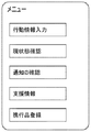
状態情報受信部341は、対処員の携帯端末5から送信された状態情報を受信する機能を備えている。状態情報は、対処員が監視区域に所在しているか(到着しているか)否かを示す情報であり、例えば、対処員が携帯端末5を操作することによって入力され、センタ装置に送信される。図4には、携帯端末5のメニュー画面の例が示される。図4に示すように、携帯端末5のメニュー画面には、各種のメニュー項目ボタンが表示される。それらのメニュー項目ボタンのうち「行動情報入力」ボタンを対処員がタップ操作(選択操作)すると、図5に示すような行動情報入力画面が表示される。この行動情報入力画面で、対処員は「対処施設、行動内容、現状態、補足情報」などの各種の行動情報を入力することができる。
The status
「対処施設」には、監視センタから「対処」の指示を受けたときに、これから対処員が向かう監視区域の名称などが入力される。「対処施設」は、通常、センタからの対処指示に応じて自動的に入力される。「行動内容」は、対処員が行う行動の内容を示す情報であり、例えば「異常対処、保守点検、巡回、お客様対応、災害対応、工事、事務作業、状況確認」などが入力される。「現状態」は、対処員の現在の状態を示す情報であり、例えば「到着、出発、休憩中」などが含まれる。この「現状態」が状態情報に相当する。「補足情報」には、例えば「車両移動、徒歩移動」など、その他の補足情報が入力される。 In the “handling facility”, when the “handling” instruction is received from the monitoring center, the name of the monitoring area to which the counselor is going to enter is input. The “handling facility” is normally automatically input in response to a handling instruction from the center. “Behavior content” is information indicating the content of the action performed by the coordinator. For example, “abnormality handling, maintenance inspection, patrol, customer response, disaster response, construction, office work, status confirmation” or the like is input. The “current state” is information indicating the current state of the coping staff, and includes, for example, “arriving, departing, resting” and the like. This “current state” corresponds to state information. “Supplementary information” is input with other supplementary information such as “vehicle movement, walking movement”.
位置特定部342は、異常信号受信部340で受信した異常信号と、記憶部33に記憶されている設置位置情報に基づいて、異常を検知した防犯センサ7の設置位置を特定する機能を備えている。例えば、位置特定部342は、異常信号受信部340で受信した異常信号から、異常を検知した防犯センサ7の識別情報を抽出し、その識別情報をキーとして設置位置情報からその防犯センサ7の設置位置を特定する。
The
所在判断部343は、状態情報受信部341が受信した状態情報に基づいて、対処員が監視区域に所在しているか(到着しているか)否かを判断する。例えば、行動情報入力画面で対処員が入力した「現状態」が「到着」であれば、その対処員が監視区域に所在していると判断する。一方、、行動情報入力画面で対処員が入力した「現状態」が「出発」や「休憩中」であれば、その対処員が監視区域に所在していないと判断する。
The
送信制御部344は、所在判断部343により対処員が監視区域に所在していると判断された場合には、異常を検知した防犯センサ7の設置位置をその対処員の携帯端末5へ送信することを許可する。一方、送信制御部344は、所在判断部343により対処員が監視区域に所在していないと判断された場合には、異常を検知した防犯センサ7の設置位置をその対処員の携帯端末5へ送信することを禁止する。
When the
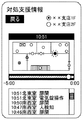
例えば、図4に示した携帯端末5のメニュー画面で「支援情報」ボタンを対処員がタップ操作(選択操作)すると、図6に示すような支援情報画面が表示される。この支援情報画面で「対処支援情報を確認」ボタンを対処員がタップ操作(選択操作)すると、図7に示すような対処支援情報画面が表示され、対処員は異常を検知した防犯センサ7の設置位置を平面図上、あるいは設置位置の名称により確認することができる。ただし、本実施の形態では、所在判断部343により対処員が監視区域に所在していないと判断されると、「対処支援情報を確認」ボタンが非アクティブ(非活性による選択不可)とされ、対処支援情報画面が表示されないようになっており、所在判断部343により対処員が監視区域に所在していると判断されると、「対処支援情報を確認」ボタンがアクティブ(活性化され選択可)とされ、対処支援情報画面を表示することができるようになる。
For example, when the coordinator taps (selects) the “support information” button on the menu screen of the
送信制御部344は、所在判断部343により対処員が監視区域に所在していると判断された場合に、警備装置2の警備モードが前回変更(警備解除モードから警備セットモードへ変更)されてから現在までの間に異常を検知した防犯センサ7の設置位置を携帯端末5へ送信してもよい。そうすると、携帯端末5のタッチパネルに、異常を検知した防犯センサ7の設置位置が検知順に表示することができる。例えば、図7の対処支援情報画面の例では、画面下部のフレームに、異常を検知した防犯センサ7の設置位置の名称が検知順に表示される。これにより、対処員は、検知された異常の履歴(何時、何処で異常が検知されたか)を時系列に沿って確認することができる。
When the
動画情報生成部345は、所定の時点において異常を検知した防犯センサ7の設置位置を監視区域の図面情報に識別可能に重畳した検知位置画像を生成し、複数の時点の検知位置画像を時刻情報に基づいて時系列に並べた動画情報を生成する機能を備えている。そして、送信制御部344は、所在判断部343により対処員が監視区域に所在していると判断された場合には、この動画情報を携帯端末5に送信することが可能である。
The moving image
この場合、動画情報生成部345は、上記の動画情報を、最新の検知位置画像を最終フレームとした動画によるストリーミング映像として生成する機能も備えている。そして、送信制御部344は、携帯端末5から過去の時点の検知位置画像について再生要求を受け付けると、現時点を基準とした相対時間情報(タイムバー)とともに再生要求のあった過去の時点の検知位置画像を開始フレームとしたストリーミング映像を携帯端末5に配信することが可能である。
In this case, the moving image
例えば、図7の対処支援情報画面の例では、画面中央のフレームに、現在(時刻10:51)の検知位置画像を最終フレームとし、携帯端末5から再生要求のあった過去の時点(時刻10:46)の検知位置画像を開始フレームとしたストリーミング映像が表示されている。そして、画面中央のフレーム下部には、現時点(時刻10:51)を基準(0:00)とした過去の時点(−5:00、すなわち時刻10:46)までの相対時間情報(タイムバー)が表示されている。このタイムバーを操作することで、ストリーミング映像の再生要求となり、携帯端末5から当該時点の検知位置画像がセンタ装置に要求される。
For example, in the example of the handling support information screen in FIG. 7, the current detected position image is the last frame in the center frame of the screen, and the past time point (time 10 : 46) a streaming video having the detected position image as a start frame is displayed. At the lower part of the frame at the center of the screen, relative time information (time bar) up to a past time (-5: 00, ie, time 10:46) with the current time (time 10:51) as a reference (0:00). Is displayed. By operating the time bar, a streaming video playback request is made, and the
以上のように構成されたセンタ装置3について、図8および図9のフロー図を参照してその動作を説明する。
The operation of the
まず、図8を参照して、センタ装置3が異常信号を受信したときの動作について説明する。図8に示すように、センタ装置3は、警備装置2から異常信号を受信すると(S1)、受信した異常信号に含まれる識別情報に基づいて、対象の監視区域と異常を検知した防犯センサ7を特定し(S2)、防犯センサ7が異常を検知した時刻情報とともに検知履歴として記憶部33に記憶する(S3)。
First, the operation when the
つぎに、センタ装置3は、異常信号と設置位置情報と図面情報に基づいて、異常を検知した防犯センサ7の設置位置を図面上で特定する(S4)。そして、現在の検知位置(現在、異常を検知している防犯センサ7)を識別可能な図面画像を最新フレームとした動画情報(ストリーミング映像)を生成する(S5)。例えば、図7の対処支援情報画面の例では、現在の検知位置が点滅した丸印で識別可能にプロット表示されている。なお、図7の例では、異常を検知した防犯センサ7が着色された丸印でプロット表示されており、検知から時間が経った防犯センサ7は、その着色の度合いが徐々に薄くなるように表示されている。
Next, the
その後、警備装置2が防犯センサ7から新たな検知信号を受信すると(S6)、センタ装置3は、上記の処理(S3〜S5)を繰り返して、最新の動画情報を作成する。そして、センタ装置3は、異常が復旧して、警備装置2の警備モードが警備セットモードから警備解除モードに設定されたら(S7)、この処理を終了する。
Thereafter, when the
つぎに、図9を参照して、センタ装置3が状態情報を受信したときの動作について説明する。図9に示すように、センタ装置3は、携帯端末5から状態情報(現状態)を受信すると(S10)、その状態情報に基づいて、その対処員の現状態が到着(監視区域に所在している)であるか否かを判断する(S11)。対処員が監視区域に所在している場合には、異常を検知した防犯センサ7の設置位置を携帯端末5へ送信することを許可(送信禁止を解除)して(S12)、例えば、WEBサーバ上の異常対処の支援ページへの携帯端末5からのアクセスを許可する(S13)。そして、そのWEBサーバ上の異常対処の支援ページに、現在の検知位置を識別可能な図面画像を最新フレームとした動画情報(ストリーミング映像)を配信する(S14)。
Next, the operation when the
その後、センタ装置3は、対処員の現状態に変化があるか、すなわち、監視区域に所在していないに変化したか否かを判断するとともに(S15)、異常が復旧したか、すなわち、警備装置2の警備モードが警備セットモードから警備解除モードに設定されたか否かを判断する(S16)。そして、対処員の現状態に変化があった場合には、異常を検知した防犯センサ7の設置位置を携帯端末5へ送信することを禁止する(S17)。また、対処員の現状態に変化がない場合でも、異常が復旧した場合には、異常を検知した防犯センサ7の設置位置を携帯端末5へ送信することを禁止する(S17)。
Thereafter, the
このような本実施の形態の警備業務支援システム1によれば、対処員が監視区域に所在している場合には、異常を検知した防犯センサ7の設置位置の情報が対処員の携帯端末5へ送信される。一方、対処員が監視区域に所在していない場合には、異常を検知した防犯センサ7の設置位置の情報が対処員の携帯端末5へ送信されない。このようにして、対処員の状態(監視区域に所在しているか否か)に応じて、異常を検知した防犯センサ7の設置位置の情報を携帯端末5に送信するか否かを決定することができる。一般に、異常に対処する対処員が現地に到着するまでは、検知した異常についての詳細な情報を伝えることは、思い込みを排除する上で好ましくない。例えば、対処員が早い段階で詳細な情報を得ることにより、異常の場所、程度、確度について対処員が思い込みを抱くと、侵入者などの緊急の脅威があり得る状況で油断や緊張感低下を招くおそれがある。
According to such a security
本実施の形態によれば、対処員が監視区域に所在していることを条件に、異常を検知した防犯センサ7の設置位置の情報が対処員の携帯端末5に送信される。これにより、対処員の状態(監視区域に所在しているか否か)に応じた適切なタイミングで情報送信が可能になる。現場外で情報送信することによる情報が外部に漏えいすることを防止できるとともに、適切なタイミングで対処員に情報開示でき、情報がないまま対処することによる不安全さを解消して、対処員の身の安全を確保することが可能になる。
According to the present embodiment, information on the installation position of the
また、本実施の形態では、警備装置2の警備モードが前回変更(警備解除モードから警備セットモードへ変更)されてから現在までの間に異常を検知した防犯センサ7の設置位置が、携帯端末5へ送信される。そして、携帯端末5の画面に、その異常を検知した防犯センサ7の設置位置が検知順に表示される。このようにして、より必要度の高い情報(最近異常を検知した防犯センサ7の設置位置の情報)が携帯端末5へ送信され、携帯端末5の画面に分かりやすく(異常を検知した順に)表示される。これにより、対処員は異常の発生(異常の検知)の流れを容易に把握することができる。
Moreover, in this Embodiment, the installation position of the
また、本実施の形態では、センタ装置3で、異常を検知した防犯センサ7の設置位置が監視区域の図面情報に識別可能に重畳された検知位置画像を時系列に並べた動画情報が生成され、対処員が監視区域に所在している場合に、その動画情報が対処員の携帯端末5へ送信される。この動画情報により、対処員は異常の発生(異常の検知)の流れを容易に把握することができる。
Further, in the present embodiment, the
また、本実施の形態では、センタ装置3で、最新の検知位置画像を最終フレームとしたストリーミング映像が生成される。そして、携帯端末5から過去の時点の検知位置画像について再生要求を受け付けると、現時点を基準とした相対時間情報とともに、携帯端末5から再生要求のあった過去の時点の検知位置画像を開始フレームとしたストリーミング映像が携帯端末5に配信される。このストリーミング映像の配信(ストリーミング配信)により、対処員は異常の発生(異常の検知)の流れを容易に把握することができる。
In the present embodiment, the
以上、本発明の実施の形態を例示により説明したが、本発明の範囲はこれらに限定されるものではなく、請求項に記載された範囲内において目的に応じて変更・変形することが可能である。 The embodiments of the present invention have been described above by way of example, but the scope of the present invention is not limited to these embodiments, and can be changed or modified according to the purpose within the scope of the claims. is there.
例えば、動画情報(ストリーミング映像)を生成して携帯端末5へ配信する機能を、警備装置2が備えてもよい。その場合、例えば、図10に示すように、警備装置2の制御部25が、状態情報受信部254、位置特定部255、所在判断部256、送信制御部257、動画情報生成部258を備えていればよい。状態情報は、センタ装置3を経由して取得してよい。これらの状態情報受信部254、位置特定部255、所在判断部256、送信制御部257、動画情報生成部258の機能は、上述した状態情報受信部341、位置特定部342、所在判断部343、送信制御部344、動画情報生成部345と同様である。
For example, the
また、この場合、警備装置2の記憶部24に、監視区域に設置されている各防犯センサ7の設置位置が、それぞれの防犯センサ7の識別情報に関連付けられて、予め設置位置情報として記憶されている。また、この記憶部24に、防犯センサ7が異常を検知した時刻を示す時刻情報が、その異常を検知した防犯センサ7の識別情報に関連付けて記憶されている。さらに、この記憶部24に、監視区域の平面図(施設のエリアマップや邸宅のフロアマップなど)が予め図面情報として記憶されている。
Moreover, in this case, the installation position of each
このような警備装置2について、図11のフロー図を参照してその動作を説明する。警備装置2は、防犯センサ7から検知信号を受信して異常と判定すると(S20)、受信した検知信号に含まれる識別情報に基づいて、対象の監視区域と異常を検知した防犯センサ7を特定し(S21)、防犯センサ7が異常を検知した時刻情報とともに検知履歴として記憶部24に記憶する(S22)。
The operation of the
つぎに、警備装置2は、異常信号と設置位置情報と図面情報に基づいて、異常を検知した防犯センサ7の設置位置を図面上で特定する(S23)。そして、現在の検知位置(現在、異常を検知している防犯センサ7)を識別可能な図面画像を最新フレームとした動画情報(ストリーミング映像)を生成する(S24)。例えば、図7の対処支援情報画面の例では、現在の検知位置が点滅した丸印で識別可能にプロット表示されている。なお、図7の例では、異常を検知した防犯センサ7が着色された丸印でプロット表示されており、検知から時間が経った防犯センサ7は、その着色の度合いが徐々に薄くなるように表示されている。
Next, the
その後、防犯センサ7から新たな検知信号を受信すると(S25)、警備装置2は、上記の処理(S22〜S24)を繰り返して、最新の動画情報を作成する。そして、警備装置2は、携帯端末5から状態情報を受信するまでこの処理を繰り返す(S26)。
Thereafter, when a new detection signal is received from the security sensor 7 (S25), the
警備装置2は、携帯端末5から状態情報(現状態)を受信すると(S27)、その状態情報に基づいて、その対処員の現状態が到着(監視区域に所在している)であるか否かを判断する(S28)。対処員が監視区域に所在している場合には、異常を検知した防犯センサ7の設置位置を携帯端末5へ送信することを許可(送信禁止を解除)して(S29)、例えば、警備装置2をWEBサーバとして機能させ、WEBサーバ上の異常対処の支援ページへの携帯端末5からのアクセスを許可する(S30)。そして、そのWEBサーバ上の異常対処の支援ページに、現在の検知位置を識別可能な図面画像を最新フレームとした動画情報(ストリーミング映像)を配信する(S31)。
When the
その後、警備装置2は、対処員の現状態に変化があるか、すなわち、監視区域に所在していないに変化したか否かを判断するとともに(S32)、異常が復旧したか、すなわち、警備装置2の警備モードが警備セットモードから警備解除モードに設定されたか否かを判断する(S33)。そして、対処員の現状態に変化があった場合には、異常を検知した防犯センサ7の設置位置を携帯端末5へ送信することを禁止する(S34)。また、対処員の現状態に変化がない場合でも、異常が復旧した場合には、異常を検知した防犯センサ7の設置位置を携帯端末5へ送信することを禁止する(S34)。
Thereafter, the
このような警備装置2によっても、対処員が監視区域に所在していることを条件に、異常を検知した防犯センサ7の設置位置の情報が対処員の携帯端末5に送信される。これにより、対処員の状態(監視区域に所在しているか否か)に応じた適切なタイミングで情報送信が可能になる。現場外で情報送信することによる情報が外部に漏えいするのを防止できるとともに、適切なタイミングで対処員に情報開示でき、対処員の身の安全を確保することが可能になる。
Also with such a
以上のように、本発明にかかる警備業務支援システムは、監視区域の異常に対処する利用者に、その異常についての情報を適切なタイミングで送信することができるという効果を有し、施設や邸宅の警備等に用いられ、有用である。 As described above, the security service support system according to the present invention has an effect that information on the abnormality can be transmitted to a user who deals with the abnormality in the monitored area at an appropriate timing, and the facility or the residence. It is useful for security of the
1 警備業務支援システム
2 警備装置
3 センタ装置
4 ネットワーク
5 携帯端末
6 基地局
7 防犯センサ
20 操作部
21 通信部
22 表示部
23 入出力部
24 記憶部
25 制御部
250 モード設定部
251 検知信号受信部
252 異常判定部
253 異常信号送信部
254 状態情報受信部
255 位置特定部
256 所在判断部
257 送信制御部
258 動画情報生成部
30 通信部
31 表示部
32 操作部
33 記憶部
34 制御部
340 異常信号受信部
341 状態情報受信部
342 位置特定部
343 所在判断部
344 送信制御部
345 動画情報生成部
50 通信部
51 タッチパネル
DESCRIPTION OF
Claims (5)
前記警備装置は、
監視区域に設置された検知器から、異常を検知したことを示す検知信号を受信する検知信号受信部と、
異常を検知した前記検知器の識別情報を含む異常信号を、前記センタ装置に送信する異常信号送信部と、
を備え、
前記センタ装置は、
前記警備装置から送信された前記異常信号を受信する異常信号受信部と、
前記監視区域の警備を行う利用者の携帯端末から送信された、当該利用者が当該監視区域に所在しているか否かを示す状態情報を受信する状態情報受信部と、
前記検知器の設置位置を前記検知器の識別情報に関連付けて設置位置情報として記憶する記憶部と、
前記異常信号と前記設置位置情報に基づいて、異常を検知した前記検知器の設置位置を特定する位置特定部と、
前記状態情報に基づいて、前記利用者が前記監視区域に所在しているか否かを判断する所在判断部と、
前記利用者が監視区域に所在していると判断される場合には、異常を検知した前記検知器の設置位置を前記携帯端末へ送信することを許可し、前記利用者が前記監視区域に所在していないと判断される場合には、異常を検知した前記検知器の設置位置を前記携帯端末へ送信することを禁止する送信制御部と、
を備えることを特徴とする警備業務支援システム。 A security service support system comprising a security device installed in a monitoring area and a remote center device that receives a signal from the security device,
The security device
A detection signal receiving unit for receiving a detection signal indicating that an abnormality has been detected from a detector installed in the monitoring area;
An abnormal signal including identification information of the detector that has detected an abnormality, an abnormal signal transmission unit that transmits to the center device;
With
The center device is
An abnormal signal receiving unit for receiving the abnormal signal transmitted from the security device;
A state information receiving unit that receives state information transmitted from a mobile terminal of a user who performs security in the monitoring area and indicating whether or not the user is located in the monitoring area;
A storage unit that stores the installation position of the detector as installation position information in association with the identification information of the detector;
Based on the abnormality signal and the installation position information, a position specifying unit that specifies an installation position of the detector that has detected an abnormality,
A location determination unit that determines whether the user is located in the monitoring area based on the status information;
When it is determined that the user is located in the monitoring area, the installation position of the detector that has detected an abnormality is permitted to be transmitted to the mobile terminal, and the user is located in the monitoring area. If it is determined that it is not, a transmission control unit that prohibits transmission of the installation position of the detector that has detected an abnormality to the mobile terminal;
A security service support system characterized by comprising:
前記センタ装置の送信制御部は、前記利用者が監視区域に所在していると判断される場合には、前記警備装置の警備モードが前回変更されてから現在までの間に異常を検知した前記検知器の設置位置を前記携帯端末へ送信し、前記携帯端末の表示部に、前記異常を検知した前記検知器の設置位置を検知順に表示させる、請求項1に記載の警備業務支援システム。 The security device further includes a mode setting unit capable of setting a plurality of security modes,
When it is determined that the user is located in a monitoring area, the transmission control unit of the center device has detected an abnormality between the last time the security mode of the security device was changed and the present time. The security work support system according to claim 1, wherein the installation position of the detector is transmitted to the mobile terminal, and the installation position of the detector that has detected the abnormality is displayed on the display unit of the mobile terminal in the order of detection.
前記センタ装置は、
さらに、所定の時点において前記異常を検知した前記検知器の設置位置を前記監視区域の図面情報に識別可能に重畳した検知位置画像を生成し、複数の時点の前記検知位置画像を前記時刻情報に基づいて時系列に並べた動画情報を生成する動画情報生成部を備え、
前記センタ装置の送信制御部は、前記利用者が監視区域に所在していると判断される場合には、前記動画情報生成部により生成された前記動画情報を前記異常を検知した検知器の設置位置として前記携帯端末に送信する、請求項1または2に記載の警備業務支援システム。 The storage unit of the center device further stores time information indicating a time at which the detector detects an abnormality in association with identification information of the detector that has detected the abnormality, and drawing information of the monitoring area. Remember,
The center device is
Furthermore, a detection position image in which the installation position of the detector that has detected the abnormality at a predetermined time point is identifiably superimposed on the drawing information of the monitoring area is generated, and the detection position images at a plurality of time points are used as the time information. A video information generation unit that generates video information arranged in time series based on
When it is determined that the user is located in a monitoring area, the transmission control unit of the center device installs a detector that detects the abnormality in the moving image information generated by the moving image information generation unit. The security service support system according to claim 1, wherein the security service support system transmits the position to the portable terminal.
前記送信制御部は、前記携帯端末から過去の時点の検知位置画像について再生要求を受け付けると、現時点を基準とした相対時間情報とともに前記再生要求のあった過去の時点の検知位置画像を開始フレームとした前記ストリーミング映像を前記携帯端末に配信する、請求項3に記載の警備業務支援システム。 The moving image information generation unit generates the moving image information as a streaming image by a moving image with the latest detected position image as a final frame,
When the transmission control unit receives a reproduction request for a detected position image at a past time from the portable terminal, the transmission position detection unit uses the detected position image at the past time when the reproduction request has been made, together with relative time information based on the current time as a start frame. The security service support system according to claim 3, wherein the streaming video is delivered to the mobile terminal.
監視区域に設置された検知器から、異常を検知したことを示す検知信号を受信する検知信号受信部と、
前記監視区域の警備を行う利用者の携帯端末から送信された、当該利用者が当該監視区域に所在しているか否かを示す状態情報を受信する状態情報受信部と、
前記検知器の設置位置を前記検知器の識別情報に関連付けて設置位置情報として記憶する記憶部と、
異常を検知した前記検知器の識別情報を含む異常信号と前記設置位置情報に基づいて、異常を検知した前記検知器の設置位置を特定する位置特定部と、
前記状態情報に基づいて、前記利用者が前記監視区域に所在しているか否かを判断する所在判断部と、
前記利用者が監視区域に所在していると判断される場合には、異常を検知した前記検知器の設置位置を前記携帯端末へ送信することを許可し、前記利用者が前記監視区域に所在していないと判断される場合には、異常を検知した前記検知器の設置位置を前記携帯端末へ送信することを禁止する送信制御部と、
を備えることを特徴とする警備装置。
A security device installed in a surveillance area,
A detection signal receiving unit for receiving a detection signal indicating that an abnormality has been detected from a detector installed in the monitoring area;
A state information receiving unit that receives state information transmitted from a mobile terminal of a user who performs security in the monitoring area and indicating whether or not the user is located in the monitoring area;
A storage unit that stores the installation position of the detector as installation position information in association with the identification information of the detector;
Based on an abnormal signal including identification information of the detector that has detected an abnormality and the installation position information, a position specifying unit that specifies an installation position of the detector that has detected an abnormality,
A location determination unit that determines whether the user is located in the monitoring area based on the status information;
When it is determined that the user is located in the monitoring area, the installation position of the detector that has detected an abnormality is permitted to be transmitted to the mobile terminal, and the user is located in the monitoring area. If it is determined that it is not, a transmission control unit that prohibits transmission of the installation position of the detector that has detected an abnormality to the mobile terminal;
A security device comprising:
Priority Applications (1)
| Application Number | Priority Date | Filing Date | Title |
|---|---|---|---|
| JP2016023462A JP6599261B2 (en) | 2016-02-10 | 2016-02-10 | Security service support system and security device |
Applications Claiming Priority (1)
| Application Number | Priority Date | Filing Date | Title |
|---|---|---|---|
| JP2016023462A JP6599261B2 (en) | 2016-02-10 | 2016-02-10 | Security service support system and security device |
Publications (3)
| Publication Number | Publication Date |
|---|---|
| JP2017142649A JP2017142649A (en) | 2017-08-17 |
| JP2017142649A5 JP2017142649A5 (en) | 2018-10-11 |
| JP6599261B2 true JP6599261B2 (en) | 2019-10-30 |
Family
ID=59627930
Family Applications (1)
| Application Number | Title | Priority Date | Filing Date |
|---|---|---|---|
| JP2016023462A Active JP6599261B2 (en) | 2016-02-10 | 2016-02-10 | Security service support system and security device |
Country Status (1)
| Country | Link |
|---|---|
| JP (1) | JP6599261B2 (en) |
Families Citing this family (1)
| Publication number | Priority date | Publication date | Assignee | Title |
|---|---|---|---|---|
| CN116089223B (en) * | 2023-03-14 | 2023-06-16 | 联动优势电子商务有限公司 | Service operation monitoring system and monitoring method |
Family Cites Families (5)
| Publication number | Priority date | Publication date | Assignee | Title |
|---|---|---|---|---|
| JP3553332B2 (en) * | 1997-09-11 | 2004-08-11 | セコム株式会社 | Wireless security system |
| JP2003228781A (en) * | 2002-02-04 | 2003-08-15 | Nishi Nippon Keibi Hosho Kk | Security system and processing method for it |
| JP4671736B2 (en) * | 2005-03-31 | 2011-04-20 | 綜合警備保障株式会社 | Monitoring center, monitoring system, monitoring method, monitoring program |
| JP6486611B2 (en) * | 2014-05-27 | 2019-03-20 | 能美防災株式会社 | Support system |
| US9582975B2 (en) * | 2015-01-27 | 2017-02-28 | Honeywell International Inc. | Alarm routing in integrated security system based on security guards real-time location information in the premises for faster alarm response |
-
2016
- 2016-02-10 JP JP2016023462A patent/JP6599261B2/en active Active
Also Published As
| Publication number | Publication date |
|---|---|
| JP2017142649A (en) | 2017-08-17 |
Similar Documents
| Publication | Publication Date | Title |
|---|---|---|
| US9819911B2 (en) | Home, office security, surveillance system using micro mobile drones and IP cameras | |
| US9449482B2 (en) | Method and apparatus for activating and deactivating video cameras in a security system | |
| KR100767065B1 (en) | Remote monitoring system and method thereof | |
| EP3051510B1 (en) | Improved alarm routing in integrated security system based on security guard s real-time location information in the premises for faster alarm response | |
| KR200414008Y1 (en) | System for monitoring fire signals | |
| US20150077566A1 (en) | Method of Installing PIR Sensor with Camera | |
| KR20160122386A (en) | Sensors gather information for the elderly to prevent anti Kodokushi. During event monitoring possible things Internet-based video management system | |
| JP2019219844A (en) | Radio disaster prevention system, and disaster prevention method thereof | |
| JP5009206B2 (en) | Security equipment | |
| JP5198101B2 (en) | Security equipment | |
| JP6599261B2 (en) | Security service support system and security device | |
| JP2023162263A (en) | Security system, portable terminal, and program | |
| JP6641176B2 (en) | Security service support system and security device | |
| WO2019224116A2 (en) | Fire alarm system integration | |
| JP2012128890A (en) | Security device and security system | |
| KR101042368B1 (en) | Security system and control method | |
| JP5270287B2 (en) | Monitoring device, fire reporting system, and reporting device | |
| JP2017117141A (en) | Guard business support system and guard device | |
| US9990821B2 (en) | Method of restoring camera position for playing video scenario | |
| JP6574694B2 (en) | Security device and security service support system | |
| JP6776167B2 (en) | Security systems, mobile terminals, security devices, security methods and programs | |
| JP6297384B2 (en) | Security device, security system, and security mode setting method | |
| JP2022177446A (en) | Security system, mobile terminal, and program | |
| JP2009245086A (en) | Guard device | |
| JP5107115B2 (en) | Security equipment |
Legal Events
| Date | Code | Title | Description |
|---|---|---|---|
| A521 | Request for written amendment filed |
Free format text: JAPANESE INTERMEDIATE CODE: A523 Effective date: 20180903 |
|
| A621 | Written request for application examination |
Free format text: JAPANESE INTERMEDIATE CODE: A621 Effective date: 20180903 |
|
| A977 | Report on retrieval |
Free format text: JAPANESE INTERMEDIATE CODE: A971007 Effective date: 20190816 |
|
| TRDD | Decision of grant or rejection written | ||
| A01 | Written decision to grant a patent or to grant a registration (utility model) |
Free format text: JAPANESE INTERMEDIATE CODE: A01 Effective date: 20190903 |
|
| A61 | First payment of annual fees (during grant procedure) |
Free format text: JAPANESE INTERMEDIATE CODE: A61 Effective date: 20191002 |
|
| R150 | Certificate of patent or registration of utility model |
Ref document number: 6599261 Country of ref document: JP Free format text: JAPANESE INTERMEDIATE CODE: R150 |
|
| R250 | Receipt of annual fees |
Free format text: JAPANESE INTERMEDIATE CODE: R250 |
|
| R250 | Receipt of annual fees |
Free format text: JAPANESE INTERMEDIATE CODE: R250 |