JP6586758B2 - Information processing system, information processing method, and program - Google Patents

Information processing system, information processing method, and program Download PDF

Info

Publication number
JP6586758B2
JP6586758B2 JP2015073833A JP2015073833A JP6586758B2 JP 6586758 B2 JP6586758 B2 JP 6586758B2 JP 2015073833 A JP2015073833 A JP 2015073833A JP 2015073833 A JP2015073833 A JP 2015073833A JP 6586758 B2 JP6586758 B2 JP 6586758B2
Authority
JP
Japan
Prior art keywords
information
display
real object
processing system
information processing
Prior art date
Legal status (The legal status is an assumption and is not a legal conclusion. Google has not performed a legal analysis and makes no representation as to the accuracy of the status listed.)
Active
Application number
JP2015073833A
Other languages
Japanese (ja)
Other versions
JP2016194762A5 (en
JP2016194762A (en
Inventor
哲男 池田
哲男 池田
斉藤 博
博 斉藤
まや 蒲池
まや 蒲池
優 林
優 林
Current Assignee (The listed assignees may be inaccurate. Google has not performed a legal analysis and makes no representation or warranty as to the accuracy of the list.)
Sony Corp
Original Assignee
Sony Corp
Priority date (The priority date is an assumption and is not a legal conclusion. Google has not performed a legal analysis and makes no representation as to the accuracy of the date listed.)
Filing date
Publication date
Priority to JP2015073833A priority Critical patent/JP6586758B2/en
Application filed by Sony Corp filed Critical Sony Corp
Priority to EP16711901.5A priority patent/EP3278197B1/en
Priority to US15/541,576 priority patent/US10423283B2/en
Priority to PCT/JP2016/000952 priority patent/WO2016157703A1/en
Priority to CN201680017769.1A priority patent/CN107407967B/en
Publication of JP2016194762A publication Critical patent/JP2016194762A/en
Publication of JP2016194762A5 publication Critical patent/JP2016194762A5/ja
Priority to US16/536,930 priority patent/US20190369808A1/en
Application granted granted Critical
Publication of JP6586758B2 publication Critical patent/JP6586758B2/en
Active legal-status Critical Current
Anticipated expiration legal-status Critical

Links

Images

Classifications

    • GPHYSICS
    • G06COMPUTING; CALCULATING OR COUNTING
    • G06FELECTRIC DIGITAL DATA PROCESSING
    • G06F3/00Input arrangements for transferring data to be processed into a form capable of being handled by the computer; Output arrangements for transferring data from processing unit to output unit, e.g. interface arrangements
    • G06F3/01Input arrangements or combined input and output arrangements for interaction between user and computer
    • G06F3/011Arrangements for interaction with the human body, e.g. for user immersion in virtual reality
    • GPHYSICS
    • G06COMPUTING; CALCULATING OR COUNTING
    • G06FELECTRIC DIGITAL DATA PROCESSING
    • G06F3/00Input arrangements for transferring data to be processed into a form capable of being handled by the computer; Output arrangements for transferring data from processing unit to output unit, e.g. interface arrangements
    • G06F3/01Input arrangements or combined input and output arrangements for interaction between user and computer
    • G06F3/03Arrangements for converting the position or the displacement of a member into a coded form
    • G06F3/041Digitisers, e.g. for touch screens or touch pads, characterised by the transducing means
    • G06F3/042Digitisers, e.g. for touch screens or touch pads, characterised by the transducing means by opto-electronic means
    • G06F3/0425Digitisers, e.g. for touch screens or touch pads, characterised by the transducing means by opto-electronic means using a single imaging device like a video camera for tracking the absolute position of a single or a plurality of objects with respect to an imaged reference surface, e.g. video camera imaging a display or a projection screen, a table or a wall surface, on which a computer generated image is displayed or projected
    • GPHYSICS
    • G06COMPUTING; CALCULATING OR COUNTING
    • G06FELECTRIC DIGITAL DATA PROCESSING
    • G06F16/00Information retrieval; Database structures therefor; File system structures therefor
    • G06F16/20Information retrieval; Database structures therefor; File system structures therefor of structured data, e.g. relational data
    • G06F16/23Updating
    • GPHYSICS
    • G06COMPUTING; CALCULATING OR COUNTING
    • G06FELECTRIC DIGITAL DATA PROCESSING
    • G06F16/00Information retrieval; Database structures therefor; File system structures therefor
    • G06F16/40Information retrieval; Database structures therefor; File system structures therefor of multimedia data, e.g. slideshows comprising image and additional audio data
    • G06F16/43Querying
    • G06F16/435Filtering based on additional data, e.g. user or group profiles
    • GPHYSICS
    • G06COMPUTING; CALCULATING OR COUNTING
    • G06FELECTRIC DIGITAL DATA PROCESSING
    • G06F3/00Input arrangements for transferring data to be processed into a form capable of being handled by the computer; Output arrangements for transferring data from processing unit to output unit, e.g. interface arrangements
    • G06F3/01Input arrangements or combined input and output arrangements for interaction between user and computer
    • G06F3/048Interaction techniques based on graphical user interfaces [GUI]
    • G06F3/0481Interaction techniques based on graphical user interfaces [GUI] based on specific properties of the displayed interaction object or a metaphor-based environment, e.g. interaction with desktop elements like windows or icons, or assisted by a cursor's changing behaviour or appearance

Description

本開示は、情報処理システム、情報処理方法及びプログラムに関する。   The present disclosure relates to an information processing system, an information processing method, and a program.

スマートフォンやタブレット端末などの、タッチパネルに対する操作によって様々な情報を表示する装置が、広く普及している。タブレット端末については、画面サイズの大型化も図られるようになり、複数のユーザが同時に操作する使われ方も考慮されるようになりつつある。また、情報を表示する装置としては、従来からプロジェクタが用いられている。   Devices that display various kinds of information by operations on touch panels, such as smartphones and tablet terminals, are widely used. With regard to tablet terminals, the screen size has been increased, and the use method in which a plurality of users operate at the same time is being considered. In addition, a projector is conventionally used as a device for displaying information.

このような情報を表示する装置の普及に伴い、表示された情報に対する多様な操作を可能にするための様々なユーザインタフェースが提案されている。例えば、下記特許文献1では、携帯端末により撮影等された画像をキーとしてデータベースを参照することで、URLなどの対応する情報を読み出す技術が開示されている。   With the widespread use of devices that display such information, various user interfaces have been proposed for enabling various operations on the displayed information. For example, Patent Document 1 below discloses a technique for reading out corresponding information such as a URL by referring to a database using an image taken by a mobile terminal as a key.

特開2006−48672号公報JP 2006-48672 A

情報が表示される際の装置の周囲の環境や、表示されている情報の状況は、常に一定であるとは限らない。例えば装置の周囲には多様な実オブジェクトが存在し得、また多様な表示オブジェクトが表示され得る。上記事情に鑑みれば、実オブジェクトや表示オブジェクトに応じた適切かつ効率的な情報の表示により、ユーザの利便性を向上させることが求められる。   The environment around the device when information is displayed and the status of the displayed information are not always constant. For example, various real objects may exist around the device, and various display objects may be displayed. In view of the above circumstances, it is required to improve user convenience by displaying information appropriately and efficiently according to real objects and display objects.

そこで本開示では、ユーザの利便性を向上させることが可能な、新規かつ改良された情報処理システム、情報処理方法及びプログラムを提案する。   Therefore, the present disclosure proposes a new and improved information processing system, information processing method, and program capable of improving user convenience.

本開示によれば、表示オブジェクトが表示される物体表面における前記表示オブジェクト及び実オブジェクトの認識結果に基づいて、認識された前記表示オブジェクト又は前記実オブジェクトの少なくともいずれかに対応する提供情報を表示部に表示させる表示制御部、を備える情報処理システムが提供される。   According to the present disclosure, based on the recognition result of the display object and the real object on the object surface on which the display object is displayed, the provided information corresponding to at least one of the recognized display object or the real object is displayed on the display unit. There is provided an information processing system including a display control unit to be displayed.

また、本開示によれば、表示オブジェクトが表示される物体表面における前記表示オブジェクト及び実オブジェクトの認識結果に基づいて、認識された前記表示オブジェクト又は前記実オブジェクトの少なくともいずれかに対応する提供情報を表示部に表示させるようプロセッサにより制御すること、を含む情報処理方法が提供される。   Further, according to the present disclosure, provided information corresponding to at least one of the recognized display object or the real object based on the recognition result of the display object and the real object on the surface of the object on which the display object is displayed. There is provided an information processing method including controlling by a processor to display on a display unit.

また、本開示によれば、コンピュータを、表示オブジェクトが表示される物体表面における前記表示オブジェクト及び実オブジェクトの認識結果に基づいて、認識された前記表示オブジェクト又は前記実オブジェクトの少なくともいずれかに対応する提供情報を表示部に表示させる表示制御部、として機能させるためのプログラムが提供される。   According to the present disclosure, the computer corresponds to at least one of the display object or the real object recognized based on the recognition result of the display object and the real object on the surface of the object on which the display object is displayed. A program for causing a display control unit to display provided information on a display unit is provided.

以上説明したように本開示によれば、ユーザの利便性を向上させることが可能である。なお、上記の効果は必ずしも限定的なものではなく、上記の効果とともに、または上記の効果に代えて、本明細書に示されたいずれかの効果、または本明細書から把握され得る他の効果が奏されてもよい。   As described above, according to the present disclosure, user convenience can be improved. Note that the above effects are not necessarily limited, and any of the effects shown in the present specification, or other effects that can be grasped from the present specification, together with or in place of the above effects. May be played.

本実施形態に係る情報処理システムの外観構成例を示す図である。It is a figure showing an example of appearance composition of an information processing system concerning this embodiment. 本実施形態に係る情報処理システムの外観構成例を示す図である。It is a figure showing an example of appearance composition of an information processing system concerning this embodiment. 本実施形態に係る情報処理システムの外観構成例を示す図である。It is a figure showing an example of appearance composition of an information processing system concerning this embodiment. 本実施形態に係る情報処理システムの論理的な構成の一例を示すブロック図である。It is a block diagram which shows an example of a logical structure of the information processing system which concerns on this embodiment. 本実施形態に係る情報処理システムの論理的な構成の一例を示すブロック図である。It is a block diagram which shows an example of a logical structure of the information processing system which concerns on this embodiment. 本実施形態に係る情報処理システムにおいて実行される対応関係DBの更新処理の流れの一例を示すフローチャートである。It is a flowchart which shows an example of the flow of the update process of correspondence DB performed in the information processing system which concerns on this embodiment. 本実施形態に係る情報処理システムにおいて実行される実オブジェクト認識処理の流れの一例を示すフローチャートである。It is a flowchart which shows an example of the flow of the real object recognition process performed in the information processing system which concerns on this embodiment. 本実施形態に係る情報処理システムにおいて実行される実オブジェクト同定処理の流れの一例を示すフローチャートである。It is a flowchart which shows an example of the flow of the real object identification process performed in the information processing system which concerns on this embodiment. 本実施形態に係る位置マップの取得処理の一例を説明するための図である。It is a figure for demonstrating an example of the acquisition process of the position map which concerns on this embodiment. 本実施形態に係る位置マップの一致率の算出処理の一例を説明するための図である。It is a figure for demonstrating an example of the calculation process of the coincidence rate of the position map which concerns on this embodiment. 本実施形態に係る情報処理システムにおいて実行される実オブジェクトDB更新処理の流れの一例を示すフローチャートである。It is a flowchart which shows an example of the flow of the real object DB update process performed in the information processing system which concerns on this embodiment. 本実施形態に係る実オブジェクトDBにおける位置マップの更新処理の一例を説明するための図である。It is a figure for demonstrating an example of the update process of the position map in real object DB which concerns on this embodiment. 本実施形態に係る情報処理システムにおいて実行される提供情報表示処理の流れの一例を示すフローチャートである。It is a flowchart which shows an example of the flow of the provision information display process performed in the information processing system which concerns on this embodiment. 本実施形態に係る情報処理システムにおいて実行される提供情報表示処理の流れの一例を示すフローチャートである。It is a flowchart which shows an example of the flow of the provision information display process performed in the information processing system which concerns on this embodiment. 本実施形態に係る表示オブジェクトDBに格納される情報の一例を示す図である。It is a figure which shows an example of the information stored in display object DB which concerns on this embodiment. 本実施形態に係る実オブジェクトDBに格納される情報の一例を示す図である。It is a figure which shows an example of the information stored in real object DB which concerns on this embodiment. 本実施形態に係る実オブジェクトDBに格納される情報の一例を示す図である。It is a figure which shows an example of the information stored in real object DB which concerns on this embodiment. 本実施形態に係る実オブジェクトの同定処理の一例を説明するための図である。It is a figure for demonstrating an example of the identification process of the real object which concerns on this embodiment. 本実施形態に係る実オブジェクトの同定処理の一例を説明するための図である。It is a figure for demonstrating an example of the identification process of the real object which concerns on this embodiment. 本実施形態に係るローカルの対応関係DBに関する処理の一例を説明するための図である。It is a figure for demonstrating an example of the process regarding local correspondence DB which concerns on this embodiment. 本実施形態に係るローカルの対応関係DBに関する処理の一例を説明するための図である。It is a figure for demonstrating an example of the process regarding local correspondence DB which concerns on this embodiment. 本実施形態に係るクラウド上の対応関係DBに関する処理の一例を説明するための図である。It is a figure for demonstrating an example of the process regarding the corresponding | compatible relationship DB on the cloud which concerns on this embodiment. 本実施形態に係るクラウド上の対応関係DBに関する処理の一例を説明するための図である。It is a figure for demonstrating an example of the process regarding the corresponding | compatible relationship DB on the cloud which concerns on this embodiment. 本実施形態に係るクラウド上の対応関係DBに関する処理の一例を説明するための図である。It is a figure for demonstrating an example of the process regarding the corresponding | compatible relationship DB on the cloud which concerns on this embodiment. 本実施形態に係るクラウド上の対応関係DBに関する処理の一例を説明するための図である。It is a figure for demonstrating an example of the process regarding the corresponding | compatible relationship DB on the cloud which concerns on this embodiment. 本実施形態に係る情報処理装置のハードウェア構成の一例を示すブロック図である。It is a block diagram which shows an example of the hardware constitutions of the information processing apparatus which concerns on this embodiment.

以下に添付図面を参照しながら、本開示の好適な実施の形態について詳細に説明する。なお、本明細書及び図面において、実質的に同一の機能構成を有する構成要素については、同一の符号を付することにより重複説明を省略する。   Hereinafter, preferred embodiments of the present disclosure will be described in detail with reference to the accompanying drawings. In addition, in this specification and drawing, about the component which has the substantially same function structure, duplication description is abbreviate | omitted by attaching | subjecting the same code | symbol.

また、本明細書及び図面において、実質的に同一の機能構成を有する要素を、同一の符号の後に異なるアルファベットを付して区別する場合もある。例えば、実質的に同一の機能構成を有する複数の要素を、必要に応じて情報処理システム100A、100B及び100Cのように区別する。ただし、実質的に同一の機能構成を有する複数の要素の各々を特に区別する必要がない場合、同一符号のみを付する。例えば、情報処理システム100A、100B及び100Cを特に区別する必要が無い場合には、単に情報処理システム100と称する。   In the present specification and drawings, elements having substantially the same functional configuration may be distinguished by adding different alphabets after the same reference numerals. For example, a plurality of elements having substantially the same functional configuration are distinguished as information processing systems 100A, 100B, and 100C as necessary. However, when there is no need to particularly distinguish each of a plurality of elements having substantially the same functional configuration, only the same reference numerals are given. For example, when it is not necessary to distinguish between the information processing systems 100A, 100B, and 100C, they are simply referred to as the information processing system 100.

なお、説明は以下の順序で行うものとする。
1.構成例
1.1.外観構成例
1.2.機能構成例
2.機能詳細
2.1.DB更新機能
2.2.提供情報表示機能
3.具体例
4.ハードウェア構成例
5.まとめ
The description will be made in the following order.
1. Configuration example 1.1. External configuration example 1.2. Functional configuration example2. Functional details 2.1. DB update function 2.2. 2. Provided information display function Specific Example 4 4. Hardware configuration example Summary

<<1.構成例>>
<1.1.外観構成例>
まず、本開示の一実施形態に係る情報処理システム100の外観構成について説明する。
<< 1. Configuration example >>
<1.1. External configuration example>
First, an external configuration of the information processing system 100 according to an embodiment of the present disclosure will be described.

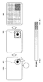
図1は、本実施形態に係る情報処理システム100Aの外観構成例を示す図である。図1に示したように、本実施形態に係る情報処理システム100Aは、入力部110Aと、出力部130Aと、を含んで形成される。図1に示した情報処理システム100Aは、テーブル140Aの天面に情報を表示し、テーブル140Aに表示した情報に対して情報処理システム100Aを使用するユーザに操作をさせるシステムである。図1のようにテーブル140Aの天面に情報を表示する方式を「プロジェクション型」とも称する。   FIG. 1 is a diagram illustrating an external configuration example of an information processing system 100A according to the present embodiment. As shown in FIG. 1, the information processing system 100A according to the present embodiment is formed to include an input unit 110A and an output unit 130A. The information processing system 100A illustrated in FIG. 1 is a system that displays information on the top surface of the table 140A and causes a user who uses the information processing system 100A to operate the information displayed on the table 140A. A method of displaying information on the top surface of the table 140A as shown in FIG. 1 is also referred to as a “projection type”.

入力部110Aは、情報処理システム100Aを使用するユーザの操作内容や、テーブル140Aに置かれている物体の形状や模様などを入力する装置である。図1に示した例では、入力部110Aは、テーブル140Aの上方に、例えば天井から吊り下げられた状態で設けられる。すなわち、入力部110Aは、情報が表示される対象となるテーブル140Aとは離隔して設けられる。入力部110Aとしては、例えば1つのレンズでテーブル140Aを撮像するカメラや、2つのレンズでテーブル140Aを撮像して奥行き方向の情報(深度情報)を記録することが可能なステレオカメラ等が用いられ得る。   The input unit 110A is a device that inputs the operation contents of the user who uses the information processing system 100A, the shape and pattern of an object placed on the table 140A, and the like. In the example illustrated in FIG. 1, the input unit 110A is provided above the table 140A, for example, in a state suspended from the ceiling. That is, the input unit 110 </ b> A is provided separately from the table 140 </ b> A on which information is displayed. As the input unit 110A, for example, a camera that images the table 140A with one lens, a stereo camera that can record information (depth information) in the depth direction by imaging the table 140A with two lenses, and the like are used. obtain.

入力部110Aとして、1つのレンズでテーブル140Aを撮像するカメラが用いられる場合、情報処理システム100Aは、そのカメラが撮像した画像を解析することで、テーブル140Aに置かれた物体を認識することが出来る。また入力部110Aとしてステレオカメラが用いられる場合、入力部110Aは、深度情報を取得することが可能となる。入力部110Aが、深度情報を取得することで、情報処理システム100Aは、例えばテーブル140Aの上に置かれた手や物体等の認識が可能になる。また入力部110Aが、深度情報を取得することで、情報処理システム100Aは、テーブル140Aへのユーザの手の接触、近接の認識やテーブル140Aからの手の離脱の認識が可能となる。なお、以下の説明では、ユーザが情報の表示面に手等の操作体を接触または近接させることを、まとめて単に「接触」とも称する。このように、入力部110Aは、テーブル140Aを撮像する画像センサ、テーブル140A上の深度情報を取得する深度センサ、及びテーブル140Aへの接触を認識するタッチセンサとしての機能を有する。   When a camera that captures the table 140A with one lens is used as the input unit 110A, the information processing system 100A can recognize an object placed on the table 140A by analyzing an image captured by the camera. I can do it. When a stereo camera is used as the input unit 110A, the input unit 110A can acquire depth information. When the input unit 110A acquires the depth information, the information processing system 100A can recognize, for example, a hand or an object placed on the table 140A. In addition, the information processing system 100A can recognize contact of the user's hand with the table 140A, recognition of proximity, and recognition of detachment of the hand from the table 140A because the input unit 110A acquires the depth information. In the following description, when the user touches or brings an operating body such as a hand in contact with the information display surface is also simply referred to as “contact”. Thus, the input unit 110A functions as an image sensor that captures the table 140A, a depth sensor that acquires depth information on the table 140A, and a touch sensor that recognizes contact with the table 140A.

以下では、ユーザの操作が、入力部110Aによって撮像された画像から認識される場合を主に説明するが、本開示は係る例に限定されるものではない。ユーザの操作は、ユーザの指等の接触を認識するタッチパネルによって認識されてもよい。また入力部110Aが取得できるユーザ操作としては、この他にも、例えば情報の表示面に対するスタイラス操作、カメラに対するジェスチャ操作等が含まれ得る。   Hereinafter, a case where a user operation is recognized from an image captured by the input unit 110A will be mainly described, but the present disclosure is not limited to such an example. The user's operation may be recognized by a touch panel that recognizes the contact of the user's finger or the like. Other user operations that can be acquired by the input unit 110 </ b> A may include, for example, a stylus operation on the information display surface, a gesture operation on the camera, and the like.

出力部130Aは、入力部110Aによって入力された、情報処理システム100Aを使用するユーザの操作内容や、出力部130Aが出力している情報の内容、テーブル140Aに置かれている物体の形状や模様等の情報に応じて、テーブル140Aに情報を表示したり、音声を出力したりする装置である。出力部130Aとしては、例えばプロジェクタやスピーカ等が用いられる。図1に示した例では、出力部130Aは、テーブル140Aの上方に、例えば天井から吊り下げられた状態で設けられる。出力部130Aがプロジェクタで形成される場合、出力部130Aは、テーブル140Aの天面に情報を投影する。   The output unit 130A is a user operation using the information processing system 100A input by the input unit 110A, information output by the output unit 130A, and a shape or pattern of an object placed on the table 140A. This is a device that displays information on the table 140A or outputs sound in accordance with such information. For example, a projector or a speaker is used as the output unit 130A. In the example illustrated in FIG. 1, the output unit 130A is provided above the table 140A, for example, in a state of being suspended from the ceiling. When the output unit 130A is formed by a projector, the output unit 130A projects information on the top surface of the table 140A.

情報処理システム100Aを使用するユーザは、出力部130Aがテーブル140Aに表示する情報に対して、指などをテーブル140Aに置いて操作することが出来る。また情報処理システム100Aを使用するユーザは、テーブル140Aに物体を置いて入力部110Aに認識させることで、その認識させた物体に関する種々の操作を実行することが出来る。   A user using the information processing system 100A can operate the information displayed on the table 140A by the output unit 130A by placing a finger or the like on the table 140A. In addition, a user who uses the information processing system 100A can execute various operations related to the recognized object by placing the object on the table 140A and causing the input unit 110A to recognize the object.

なお、図1には図示しないが、情報処理システム100Aには他の装置が接続されていても良い。例えば情報処理システム100Aには、テーブル140Aを照らすための照明機器が接続されていても良い。情報処理システム100Aにテーブル140Aを照らすための照明機器が接続されていることで、情報処理システム100Aは、情報の表示面の状態に応じて照明機器の点灯状態を制御することが可能となる。   Although not shown in FIG. 1, another device may be connected to the information processing system 100A. For example, an illumination device for illuminating the table 140A may be connected to the information processing system 100A. Since the lighting device for illuminating the table 140A is connected to the information processing system 100A, the information processing system 100A can control the lighting state of the lighting device according to the state of the information display surface.

本開示の一実施形態に係る情報処理システム100の形態は、図1に示したものに限定されるものではない。以下では、図2及び図3を参照して、本実施形態に係る情報処理システム100のさらなる別の形態の例を説明する。   The form of the information processing system 100 according to an embodiment of the present disclosure is not limited to that illustrated in FIG. Below, with reference to FIG.2 and FIG.3, the example of the further another form of the information processing system 100 which concerns on this embodiment is demonstrated.

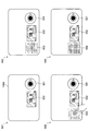
図2は、本実施形態に係る情報処理システム100Bの外観構成例を示す図である。図2に示した情報処理システム100Bでは、テーブル140Bの天面にタッチパネル式のディスプレイが形成されている。本構成例の場合、出力部130Bは、タッチパネル式のディスプレイとして形成され得る。即ち、本構成例の場合、情報の表示面はタッチパネル式のディスプレイとなる。図2のようにテーブル140Bの天面に設けたタッチパネルに情報を表示する方式を「タッチパネル型」とも称する。図2に示したように、入力部110Bは、タッチパネル式のディスプレイとして形成されてもよいし、テーブル140Bの上方にテーブル140Bとは離隔して設けられてもよい。例えば、タッチパネル式のディスプレイとして形成された入力部110Bはタッチセンサとして機能し、テーブル140Bの上方に設けられた入力部110Bは画像センサ及び深度センサとして機能する。   FIG. 2 is a diagram illustrating an external configuration example of the information processing system 100B according to the present embodiment. In the information processing system 100B shown in FIG. 2, a touch panel display is formed on the top surface of the table 140B. In the case of this configuration example, the output unit 130B can be formed as a touch panel display. That is, in the case of this configuration example, the information display surface is a touch panel display. A method of displaying information on a touch panel provided on the top surface of the table 140B as shown in FIG. 2 is also referred to as a “touch panel type”. As shown in FIG. 2, the input unit 110B may be formed as a touch panel display, or may be provided above the table 140B and separated from the table 140B. For example, the input unit 110B formed as a touch panel display functions as a touch sensor, and the input unit 110B provided above the table 140B functions as an image sensor and a depth sensor.

図3は、本実施形態に係る情報処理システム100Cの外観構成例を示す図である。図3に示した情報処理システム100Cは、テーブル140Cの下から情報を出力部130Cに照射させることで、テーブル140Cの表面に情報を表示させるように形成されているものである。すなわち、図3に示した情報処理システム100Cでは、情報の表示面はテーブル140Cの天面となる。テーブル140Cの面はガラス板や透明プラスチック板等の透明又は半透明な材質で形成される。図3のようにテーブル140Cの下から情報を出力部130Cに照射させて、テーブル140Cの天面に情報を表示する方式を「リアプロジェクション型」とも称する。図3に示したように、入力部110Cは、テーブル140Cの上方にテーブル140Cとは離隔して設けられてもよいし、テーブル140Cの下方にテーブル140Cとは離隔して設けられてもよい。例えば、テーブル140Cの上方に設けられた入力部110Cは画像センサ及び深度センサとして機能し、テーブル140Cの下方に設けられた入力部110Cはタッチセンサとして機能する。
FIG. 3 is a diagram illustrating an external configuration example of the information processing system 100C according to the present embodiment. The information processing system 100C illustrated in FIG. 3 is configured to display information on the surface of the table 140C by irradiating the output unit 130C with information from below the table 140C. That is, in the information processing system 100C shown in FIG. 3, the information display surface is the top surface of the table 140C. The surface of the table 140C is formed of a transparent or translucent material such as a glass plate or a transparent plastic plate. A method of displaying information on the top surface of the table 140C by irradiating information from the bottom of the table 140C as shown in FIG. 3 is also referred to as a “rear projection type”. As shown in FIG. 3, the input unit 110C may be provided at a distance from the table 140 C above the table 140C, the table 140C below the table 140C may be provided to be separated . For example, the input unit 110C provided above the table 140C functions as an image sensor and a depth sensor, and the input unit 110C provided below the table 140C functions as a touch sensor.

以下の説明では、図1に示したようなプロジェクション型の情報処理システム100を例にして説明する。また、アプリケーションウィンドウや画像、映像等の、出力部130により表示される情報を、表示オブジェクトとも称する。以下では、表示オブジェクトはアプリケーションウィンドウであるものとして説明する。また、テーブル140Aの天面に置かれたりかざされたりする等、情報処理システム100の周囲に存在する物体を、実オブジェクトとも称する。ユーザの体も、実オブジェクトとして捉えてもよい。表示オブジェクトは、多様な物体表面上に表示され得る。例えば、表示オブジェクトは、テーブル140Aの天面に投影されてもよいし、テーブル140A上に載置されたスクリーン等の実オブジェクト上に投影されてもよい。本明細書では、表示オブジェクトが表示される物体表面を、単に表示面とも称する。   In the following description, a projection type information processing system 100 as shown in FIG. 1 will be described as an example. Information displayed by the output unit 130 such as an application window, an image, and a video is also referred to as a display object. In the following description, it is assumed that the display object is an application window. In addition, an object that exists around the information processing system 100, such as being placed over the top of the table 140A, is also referred to as a real object. The user's body may also be regarded as a real object. Display objects can be displayed on a variety of object surfaces. For example, the display object may be projected on the top surface of the table 140A, or may be projected on a real object such as a screen placed on the table 140A. In this specification, the object surface on which the display object is displayed is also simply referred to as a display surface.

<1.2.機能構成例>
続いて、本実施形態に係る情報処理システム100の機能構成について説明する。
<1.2. Functional configuration example>
Subsequently, a functional configuration of the information processing system 100 according to the present embodiment will be described.

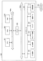
図4は、本実施形態に係る情報処理システム100の論理的な構成の一例を示すブロック図である。図4に示すように、本実施形態に係る情報処理システム100は、入力部110、制御部120、出力部130及び記憶部150を含む。   FIG. 4 is a block diagram illustrating an example of a logical configuration of the information processing system 100 according to the present embodiment. As illustrated in FIG. 4, the information processing system 100 according to the present embodiment includes an input unit 110, a control unit 120, an output unit 130, and a storage unit 150.

(1)入力部110
入力部110は、入力部110への各種情報の入力を受け付ける機能を有する。例えば、入力部110は、上述したようにテーブル140Aを撮像する画像センサ、テーブル140A上の深度情報を取得する深度センサ、及びテーブル140Aへの接触を認識するタッチセンサとしての機能を有する。出力部130により情報が表示される範囲と入力部110が情報の入力を受け付ける範囲とは、同一であってもよいし互いに相違していてもよい。例えば、入力部110は、出力部130による表示範囲より広い範囲を対象とした画像データ、深度情報、接触情報を取得し得る。
(1) Input unit 110
The input unit 110 has a function of accepting input of various information to the input unit 110. For example, as described above, the input unit 110 has a function as an image sensor that images the table 140A, a depth sensor that acquires depth information on the table 140A, and a touch sensor that recognizes contact with the table 140A. The range in which information is displayed by the output unit 130 and the range in which the input unit 110 accepts input of information may be the same or different from each other. For example, the input unit 110 can acquire image data, depth information, and contact information for a range wider than the display range by the output unit 130.

画像センサとしては、入力部110は、例えば可視光カメラ、又は赤外線カメラにより形成され得る。深度センサとしては、入力部110は、例えばステレオカメラ、time of flight方式の測距センサ、又はstructured light方式の測距センサにより形成され得る。タッチセンサとしては、入力部110は、タッチパネルにより形成されてもよいし、深度情報により接触を認識してもよい。   As the image sensor, the input unit 110 can be formed by, for example, a visible light camera or an infrared camera. As the depth sensor, the input unit 110 can be formed by, for example, a stereo camera, a time of flight distance measuring sensor, or a structured light distance measuring sensor. As a touch sensor, the input unit 110 may be formed by a touch panel, or may recognize contact based on depth information.

他にも、入力部110は、ユーザの体温や発汗、脈拍等の生体情報を取得する生体センサにより形成されていてもよい。   In addition, the input unit 110 may be formed of a biological sensor that acquires biological information such as a user's body temperature, sweating, and pulse.

(2)制御部120
制御部120は、演算処理装置および制御装置として機能し、各種プログラムに従って情報処理システム100内の動作全般を制御する。例えば制御部120は、入力部110が入力した情報を用いて、出力部130から出力する情報を生成する。図4に示すように、制御部120は、認識部122、記憶制御部124及び表示制御部126として機能する。
(2) Control unit 120
The control unit 120 functions as an arithmetic processing device and a control device, and controls the overall operation in the information processing system 100 according to various programs. For example, the control unit 120 generates information output from the output unit 130 using the information input by the input unit 110. As illustrated in FIG. 4, the control unit 120 functions as a recognition unit 122, a storage control unit 124, and a display control unit 126.

(2.1)認識部122
認識部122は、情報処理システム100周辺の実オブジェクトを認識する機能を有する。例えば、認識部122は、表示オブジェクトが表示される物体(例えば、図1に示したテーブル140A)表面における表示オブジェクト及び実オブジェクトを認識する。例えば、認識部122は、出力部130により出力される情報を参照して、表示面に表示される表示オブジェクトを認識してもよい。また、認識部122は、入力部110により入力された画像情報及び深度情報に基づいて、実オブジェクトの形状や模様等を認識してもよい。また、認識部122は、入力部110により入力されたセンシング結果に基づいて、ユーザの生体情報を認識してもよい。また、認識部122は、入力部110により入力された画像情報や深度情報に基づいて、ユーザが装着している腕時計や把持するスマートフォン等の、周辺に存在する装置を認識したりしてもよい。
(2.1) Recognition unit 122
The recognition unit 122 has a function of recognizing real objects around the information processing system 100. For example, the recognition unit 122 recognizes the display object and the real object on the surface of the object (for example, the table 140A illustrated in FIG. 1) on which the display object is displayed. For example, the recognition unit 122 may recognize a display object displayed on the display surface with reference to information output by the output unit 130. In addition, the recognition unit 122 may recognize the shape, pattern, and the like of the real object based on the image information and depth information input by the input unit 110. Further, the recognition unit 122 may recognize the user's biological information based on the sensing result input by the input unit 110. Further, the recognition unit 122 may recognize peripheral devices such as a wristwatch worn by a user and a smartphone held by the user based on the image information and depth information input by the input unit 110. .

なお、情報処理システム100が図1に示したプロジェクション型の場合、情報の表示面の座標と、ユーザの手等の操作体の表示面への接触座標とが一致するように予め校正されることで、認識部122は、ユーザの手等の操作体が、GUIのどの部分に接触したかを認識することが可能になる。   In the case where the information processing system 100 is the projection type shown in FIG. 1, the information display surface is calibrated in advance so that the coordinates of the information display surface coincide with the contact coordinates of the operation body such as the user's hand. Thus, the recognition unit 122 can recognize which part of the GUI the operating body such as the user's hand has touched.

(2.2)記憶制御部124
記憶制御部124は、記憶部150にアクセスして、情報を取得したり記憶したりする機能を有する。
(2.2) Storage control unit 124
The storage control unit 124 has a function of accessing the storage unit 150 to acquire and store information.

例えば、記憶制御部124は、認識部122により認識された表示オブジェクト及び実オブジェクトの組み合わせを対応付けた情報を、記憶部150に記憶させてもよい。これにより、同じタイミングで認識された、表示面に表示されたひとつ以上の表示オブジェクトと表示面上のひとつ以上の実オブジェクトとが対応付けられる。このような対応関係を示す情報を、以下では対応関係情報とも称する。また、記憶制御部124は、表示オブジェクトと実オブジェクトとの対応関係情報を記憶部150から取得してもよい。これにより、記憶制御部124は、過去に同じタイミングで認識された表示オブジェクトと実オブジェクトとの組み合わせを示す情報を取得することができる。   For example, the storage control unit 124 may cause the storage unit 150 to store information in which a combination of a display object and a real object recognized by the recognition unit 122 is associated. Thereby, one or more display objects displayed on the display surface recognized at the same timing are associated with one or more real objects on the display surface. Information indicating such correspondence is also referred to as correspondence information below. In addition, the storage control unit 124 may acquire correspondence information between the display object and the real object from the storage unit 150. Thereby, the storage control unit 124 can acquire information indicating a combination of a display object and a real object recognized at the same timing in the past.

記憶部150は、所定の記録媒体に対してデータの記録再生を行う部位である。記憶部150は、後述する表示オブジェクトDB(DataBase)、実オブジェクトDB、及び対応関係DBを記憶し得る。記憶部150は、情報処理システム100に固有の情報を記憶してもよいし、他の情報処理システム100との間で共有される情報を記憶してもよい。例えば、記憶部150は、情報処理システム100内に設けられてもよいし、ネットワーク等に接続されたサーバ等の別箇の装置として設けられてもよい。便宜上、本明細書では、情報処理システム100に固有の情報に関しては「ローカルの」と形容し得、他の情報処理システム100との間で共有される情報に関しては「クラウド上の」と形容し得る。   The storage unit 150 is a part that records and reproduces data on a predetermined recording medium. The storage unit 150 can store a display object DB (DataBase), a real object DB, and a correspondence relationship DB, which will be described later. The storage unit 150 may store information unique to the information processing system 100 or may store information shared with other information processing systems 100. For example, the storage unit 150 may be provided in the information processing system 100 or may be provided as a separate device such as a server connected to a network or the like. For the sake of convenience, in the present specification, information unique to the information processing system 100 may be described as “local”, and information shared with other information processing systems 100 is described as “on the cloud”. obtain.

表示オブジェクトDBは、表示オブジェクトに関する情報を格納する。例えば、表示オブジェクトDBは、下記の表1に示す情報を記憶する。識別情報は、表示オブジェクトを識別するための情報である。識別情報は、表示オブジェクトそのものを一意に識別するための情報を含んでいてもよいし、例えば表示オブジェクトが音楽プレイヤーであれば「娯楽用アプリケーション」等の表示オブジェクトのカテゴリを示す情報を含んでいてもよい。表示オブジェクトの内容は、アプリケーション種別等の表示オブジェクトの内容を示す情報である。

Figure 0006586758
The display object DB stores information related to display objects. For example, the display object DB stores information shown in Table 1 below. The identification information is information for identifying the display object. The identification information may include information for uniquely identifying the display object itself. For example, if the display object is a music player, the identification information includes information indicating the category of the display object such as “entertainment application”. Also good. The content of the display object is information indicating the content of the display object such as the application type.
Figure 0006586758

実オブジェクトDBは、実オブジェクトに関する情報を格納する。例えば、実オブジェクトDBは、下記の表2に示す情報を記憶する。識別情報は、実オブジェクトを識別するための情報である。識別情報は、実オブジェクトそのものを一意に識別するための情報を含んでいてもよいし、例えば実オブジェクトがコーヒーカップであれば「食器」等の実オブジェクトのカテゴリを示す情報を含んでいてもよい。画像情報は、入力部110により取得された画像データにより得られた、実オブジェクトの撮像画像を示す情報である。立体形状情報は、実オブジェクトの立体形状を示す情報であり、例えば入力部110により取得された実オブジェクトの深度情報である。位置マップは、入力部110により取得された深度情報により得られた、表示面における実オブジェクトの存在確率を示す情報である。他の属性情報は、実オブジェクトに関する属性を示す情報であり、例えば当該実オブジェクトが認識された時間帯を示す情報や、実オブジェクトの温度を示す情報等が含まれ得る。なお、時間帯を示す情報は、分単位、時間単位、日にち単位等の任意の単位であってもよいし、曜日や平日/休日により区別されてもよい。

Figure 0006586758
The real object DB stores information on real objects. For example, the real object DB stores information shown in Table 2 below. The identification information is information for identifying a real object. The identification information may include information for uniquely identifying the real object itself. For example, if the real object is a coffee cup, the identification information may include information indicating a category of the real object such as “tableware”. . The image information is information indicating the captured image of the real object obtained from the image data acquired by the input unit 110. The three-dimensional shape information is information indicating the three-dimensional shape of the real object, for example, depth information of the real object acquired by the input unit 110. The position map is information indicating the existence probability of the real object on the display surface obtained from the depth information acquired by the input unit 110. The other attribute information is information indicating an attribute related to the real object, and may include, for example, information indicating a time zone in which the real object is recognized, information indicating the temperature of the real object, and the like. The information indicating the time zone may be an arbitrary unit such as a minute unit, an hour unit, or a day unit, or may be distinguished by day of the week or weekday / holiday.
Figure 0006586758

対応関係DBは、対応関係情報を格納する。例えば、対応関係DBは、下記の表3に示す情報を記憶する。エントリの識別情報は、対応関係情報の識別情報である。表示オブジェクトの識別情報は、対応付けられた表示オブジェクトを識別するための識別情報であり、ひとつ以上の識別情報が含まれ得る。実オブジェクトの識別情報は、対応付けられた実オブジェクトを識別するための識別情報であり、ひとつ以上の識別情報が含まれ得る。配置情報は、実オブジェクトと表示オブジェクトとの相対的な配置を示す情報である。配置を示す情報としては、相対的な方向、距離、向き、大きさ等を含む。関連度とは、実オブジェクトと表示オブジェクトとが関連する度合を示す情報であり、例えば表示オブジェクトと実オブジェクトが同時に使用された時間や回数が増えるほど増加する。他にも、対応関係情報として、タイムラグを示す情報が含まれていてもよい。例えば、ユーザが実オブジェクトをテーブル140A上に置いてから表示オブジェクトが表示されるまでのタイムラグ、又はその逆のタイムラグを示す情報が含まれ得る。

Figure 0006586758
The correspondence DB stores correspondence information. For example, the correspondence DB stores information shown in Table 3 below. The identification information of the entry is identification information of the correspondence information. The display object identification information is identification information for identifying the associated display object, and may include one or more pieces of identification information. The identification information of the real object is identification information for identifying the associated real object, and may include one or more pieces of identification information. The arrangement information is information indicating the relative arrangement between the real object and the display object. The information indicating the arrangement includes a relative direction, distance, direction, size, and the like. The degree of association is information indicating the degree to which a real object and a display object are related. For example, the degree of association increases as the time and the number of times the display object and the real object are used simultaneously increase. In addition, information indicating a time lag may be included as the correspondence information. For example, information indicating a time lag from when the user places a real object on the table 140A until the display object is displayed, or vice versa, may be included.
Figure 0006586758

なお、上記ではDBの内容を表で示したが、例えばリレーショナルデータベース等の形式で実現されてもよい。   In the above description, the contents of the DB are shown as a table, but may be realized in a form such as a relational database.

(2.3)表示制御部126
表示制御部126は、出力部130を制御して情報を出力させる機能を有する。
(2.3) Display control unit 126
The display control unit 126 has a function of controlling the output unit 130 to output information.

例えば、表示制御部126は、入力部110により入力された情報に応じて、表示オブジェクトの表示制御を行うための表示制御信号を生成する。具体的には、表示制御部126は、表示オブジェクトの描画制御や、各表示オブジェクトへのタッチに対応する画面遷移の制御等を行う。   For example, the display control unit 126 generates a display control signal for performing display control of the display object according to the information input by the input unit 110. Specifically, the display control unit 126 performs display object drawing control, screen transition control corresponding to a touch on each display object, and the like.

例えば、表示制御部126は、認識部122による認識結果に基づいて、認識された表示オブジェクト又は前記実オブジェクトの少なくともいずれかに対応する提供情報を出力部130に表示させてもよい。これにより、ユーザは、例えば表示されている表示オブジェクトに対応する実オブジェクトに関する情報の提供を受けたり、テーブル140A上に置いている実オブジェクトに対応する表示オブジェクトに関する情報の提供を受けたりすることができる。その際、表示制御部126は、記憶制御部124により取得された対応関係情報に基づいて提供情報を表示してもよい。その場合、ユーザは、過去のユーザ自身の表示オブジェクト及び実オブジェクトの使い方、又は他のユーザの使い方に応じた内容を含む情報の提供を受けることができる。このようにして、ユーザの利便性が向上し得る。   For example, the display control unit 126 may cause the output unit 130 to display provision information corresponding to at least one of the recognized display object and the real object based on the recognition result by the recognition unit 122. Thereby, for example, the user may be provided with information regarding a real object corresponding to the displayed display object, or may be provided with information regarding a display object corresponding to the real object placed on the table 140A. it can. At that time, the display control unit 126 may display the provision information based on the correspondence information acquired by the storage control unit 124. In that case, the user can be provided with information including contents according to the usage of the display object and the real object of the past user or the usage of another user. In this way, user convenience can be improved.

提供情報の表示形態及び内容は、認識部122による認識結果により変化し得る。まず、表示形態に関して説明する。   The display form and content of the provided information may change depending on the recognition result by the recognition unit 122. First, the display form will be described.

例えば、表示制御部126は、認識された表示オブジェクト及び/又は実オブジェクトの識別情報に基づいて提供情報を表示させる位置、大きさ及び/又は姿勢といった配置を制御してもよい。具体的には、表示制御部126は、コーヒーカップ(実オブジェクト)が置かれ、ウェブブラウザ(表示オブジェクト)が表示された環境下で、コーヒーカップに対応する配置を採用してもよいし、ウェブブラウザに対応する配置を採用してもよいし、コーヒーカップ及びウェブブラウザに対応する配置を採用してもよい。また、表示制御部126は、同環境下で、カテゴリ「食器」に対応する配置を採用してもよいし、カテゴリ「娯楽用アプリケーション」に対応する配置を採用してもよいし、カテゴリ「食器」及びカテゴリ「娯楽用アプリケーション」に対応する配置を採用してもよい。   For example, the display control unit 126 may control the arrangement such as the position, size, and / or orientation at which the provided information is displayed based on the identification information of the recognized display object and / or real object. Specifically, the display control unit 126 may adopt an arrangement corresponding to a coffee cup in an environment where a coffee cup (real object) is placed and a web browser (display object) is displayed. An arrangement corresponding to the browser may be adopted, or an arrangement corresponding to the coffee cup and the web browser may be adopted. Further, the display control unit 126 may adopt an arrangement corresponding to the category “tableware”, an arrangement corresponding to the category “entertainment application”, or the category “tableware” in the same environment. ”And the category“ entertainment application ”may be employed.

また、表示制御部126は、認識された表示オブジェクト及び/又は実オブジェクトの位置に基づいて提供情報を表示させてもよい。具体的には、表示制御部126は、認識された表示オブジェクト及び/又は実オブジェクトの位置に基づいて、提供情報の配置を制御してもよい。さらに、表示制御部126は、輝度及びコントラスト等の表示パラメータを制御してもよい。これにより、ユーザは、実オブジェクトを置いた位置及び/又は表示オブジェクトを表示させた位置に応じた表示形態で、情報の提供を受けることができる。   Further, the display control unit 126 may display the provision information based on the position of the recognized display object and / or real object. Specifically, the display control unit 126 may control the arrangement of the provided information based on the position of the recognized display object and / or real object. Further, the display control unit 126 may control display parameters such as luminance and contrast. Thereby, the user can receive provision of information in a display form corresponding to the position where the real object is placed and / or the position where the display object is displayed.

表示制御部126は、表示オブジェクト及び実オブジェクトの位置の他にも、多様な情報に基づいて配置を制御し得る。例えば、表示制御部126は、下記に一例を示す情報の少なくともいずれかに基づいて配置を制御してもよい。   The display control unit 126 can control the arrangement based on various information in addition to the positions of the display object and the real object. For example, the display control unit 126 may control the arrangement based on at least one of information shown as an example below.

・実オブジェクトの位置、大きさ及び/又は姿勢
・表示オブジェクトの位置、大きさ及び/又は姿勢、
・実オブジェクトと表示オブジェクトの相対的な位置及び/又は姿勢
・表示オブジェクトに係る処理の状態
・時間帯
・ユーザプロファイル
The position, size and / or orientation of the real object, the position, size and / or orientation of the display object,
-Relative position and / or orientation of real object and display object-State of processing related to display object-Time zone-User profile

上記一例を挙げた情報によれば、表示制御部126は、同一の実オブジェクト及び/又は表示オブジェクトが認識された場合であっても、絶対的な位置、大きさ、及び/又は姿勢が異なれば異なる配置を採用し得る。また、表示制御部126は、同一の実オブジェクト及び/又は表示オブジェクトが認識された場合であっても、相対的な位置及び/又は姿勢が異なれば異なる配置を採用し得る。また、表示制御部126は、同一の表示オブジェクトが認識された場合であっても、処理中かユーザ入力待ちか等の当該表示オブジェクトの処理の状態に応じて異なる配置を採用し得る。例えば、表示制御部126は、アプリケーションがユーザ入力待ちであれば大きく提供情報を表示させ、ユーザ入力中であれば邪魔しないよう小さく提供情報を表示させてもよい。また、表示制御部126は、同一の実オブジェクト及び/又は表示オブジェクトが認識された場合であっても、時間帯及び/又はユーザプロファイルが異なれば異なる配置を採用し得る。   According to the information given as an example, the display control unit 126 can detect the same actual object and / or display object even if the absolute position, size, and / or orientation are different. Different arrangements can be employed. In addition, even when the same real object and / or display object is recognized, the display control unit 126 can adopt different arrangements as long as the relative position and / or posture are different. In addition, even when the same display object is recognized, the display control unit 126 may employ different arrangements depending on the processing state of the display object, such as whether processing is in progress or waiting for user input. For example, the display control unit 126 may display the provision information large if the application is waiting for user input, and may display the provision information small so as not to disturb the user input. In addition, even when the same real object and / or display object is recognized, the display control unit 126 can adopt different arrangements if the time zone and / or the user profile are different.

以上、表示形態に関して説明した。続いて、内容に関して説明する。   The display mode has been described above. Next, the contents will be described.

例えば、提供情報は、認識された表示オブジェクト及び/又は実オブジェクトの識別情報に基づいて生成され、表示されてもよい。具体的には、表示制御部126は、コーヒーカップが置かれ、ウェブブラウザが表示された環境下で、コーヒーカップに対応する提供情報を表示させてもよいし、ウェブブラウザに対応する提供情報を表示させてもよいし、コーヒーカップ及びウェブブラウザに対応する提供情報を表示させてもよい。また、表示制御部126は、同環境下で、カテゴリ「食器」に対応する提供情報を表示させてもよいし、カテゴリ「娯楽用アプリケーション」に対応する提供情報を表示させてもよいし、カテゴリ「食器」及びカテゴリ「娯楽用アプリケーション」に対応する提供情報を表示させてもよい。   For example, the provision information may be generated and displayed based on identification information of the recognized display object and / or real object. Specifically, the display control unit 126 may display the provision information corresponding to the coffee cup in an environment where the coffee cup is placed and the web browser is displayed, or the provision information corresponding to the web browser is displayed. You may display, and you may display the provision information corresponding to a coffee cup and a web browser. In addition, the display control unit 126 may display the provision information corresponding to the category “tableware”, the provision information corresponding to the category “entertainment application”, or the category in the same environment. The provision information corresponding to the “tableware” and the category “entertainment application” may be displayed.

ここで、表示オブジェクト及び実オブジェクトに対応する提供情報の一例を説明する。例えば、コーヒーカップが置かれ、ウェブブラウザが表示された環境下では、コーヒーカップ及びウェブブラウザに対応する提供情報として音楽プレイヤーが表示され得る。また、コーヒーカップが置かれ、ニュースアプリケーションが表示された環境下では、コーヒーカップ及びニュースアプリケーションに対応する提供情報としてスケジュールアプリケーションが表示され得る。また、雑誌が置かれ、ニュースアプリケーションが表示された環境下では、雑誌及びニュースアプリケーションに対応する提供情報として広告が表示され得る。   Here, an example of provision information corresponding to a display object and a real object will be described. For example, in an environment where a coffee cup is placed and a web browser is displayed, a music player can be displayed as provision information corresponding to the coffee cup and the web browser. Further, in an environment where a coffee cup is placed and a news application is displayed, a schedule application can be displayed as provision information corresponding to the coffee cup and the news application. Further, in an environment where a magazine is placed and a news application is displayed, an advertisement can be displayed as provided information corresponding to the magazine and the news application.

また、提供情報は、認識された表示オブジェクト及び/又は実オブジェクトの位置に基づいて生成されてもよい。具体的には、同一の表示オブジェクト及び実オブジェクトの組み合わせに係る対応関係情報であっても、配置情報が異なれば異なる対応関係情報として取り扱われる。このため、認識される表示オブジェクト及び/又は実オブジェクトの位置が異なれば、提供情報の生成のために異なる対応関係情報が参照され、異なる提供情報が生成され得る。これにより、ユーザは、実オブジェクトを置いた位置及び/又は表示オブジェクトを表示させた位置に応じた情報の提供を受けることができる。   The provided information may be generated based on the position of the recognized display object and / or real object. Specifically, even correspondence information related to a combination of the same display object and real object is handled as different correspondence information if the arrangement information is different. For this reason, if the position of the recognized display object and / or real object is different, different correspondence information is referred to in order to generate provision information, and different provision information can be generated. Thereby, the user can receive provision of information according to the position where the real object is placed and / or the position where the display object is displayed.

提供情報は、表示オブジェクト及び実オブジェクトの位置の他にも、多様な情報に基づいて生成され得る。例えば、表示制御部126は、下記に一例を示す情報の少なくともいずれかに基づいて提供情報を表示させてもよい。   The provided information can be generated based on various information in addition to the position of the display object and the real object. For example, the display control unit 126 may display the provided information based on at least one of the information shown as an example below.

・実オブジェクトの位置、大きさ及び/又は姿勢
・表示オブジェクトの位置、大きさ及び/又は姿勢、
・実オブジェクトと表示オブジェクトの相対的な位置及び/又は姿勢
・表示オブジェクトに係る処理の状態
・時間帯
・ユーザプロファイル
The position, size and / or orientation of the real object, the position, size and / or orientation of the display object,
-Relative position and / or orientation of real object and display object-State of processing related to display object-Time zone-User profile

上記一例を挙げた情報によれば、表示制御部126は、同一の実オブジェクト及び/又は表示オブジェクトが認識された場合であっても、絶対的な位置、大きさ、及び/又は姿勢が異なれば異なる提供情報を表示させ得る。また、表示制御部126は、同一の実オブジェクト及び/又は表示オブジェクトが認識された場合であっても、相対的な位置及び/又は姿勢が異なれば異なる提供情報を表示させ得る。また、表示制御部126は、同一の表示オブジェクトが認識された場合であっても、表示オブジェクトの処理の状態に応じて異なる提供情報を表示させ得る。例えば、表示制御部126は、ウェブブラウザがファイルをダウンロード中であれば待ち時間を有効活用するために音楽プレイヤーを表示させ、ダウンロード完了後はファイルマネージャを表示させてもよい。また、表示制御部126は、同一の実オブジェクト及び/又は表示オブジェクトが認識された場合であっても、時間帯及び/又はユーザプロファイルが異なれば異なる提供情報を表示させ得る。   According to the information given as an example, the display control unit 126 can detect the same actual object and / or display object even if the absolute position, size, and / or orientation are different. Different offer information may be displayed. In addition, even when the same real object and / or display object is recognized, the display control unit 126 can display different provision information if the relative position and / or orientation is different. Further, even when the same display object is recognized, the display control unit 126 can display different provision information according to the processing state of the display object. For example, if the web browser is downloading a file, the display control unit 126 may display a music player to effectively use the waiting time, and may display a file manager after the download is completed. In addition, even when the same real object and / or display object is recognized, the display control unit 126 can display different provision information if the time zone and / or the user profile are different.

以上、認識結果により変化する提供情報の表示形態及び内容について説明した。   Heretofore, the display form and contents of the provided information that changes depending on the recognition result have been described.

表示制御部126は、対応関係情報に係る組み合わせの一部が認識され、他の一部が認識されない場合、認識されていない表示オブジェクト又は実オブジェクトに関する情報を提供情報として表示し得る。提供情報は、認識部122により認識された実オブジェクトと対応関係情報において対応付けられた表示オブジェクトに関する情報であってもよい。例えば、表示制御部126は、認識された実オブジェクトに対応する表示オブジェクトがまだ表示されていない場合に、当該表示オブジェクトを表示してもよい。これにより、ユーザが例えば実オブジェクトをテーブル140A上に置くだけで、当該実オブジェクトと共に使用されることが多いアプリケーションが表示される。提供情報は、認識部122により認識された表示オブジェクトと対応関係情報において対応付けられた表示オブジェクトに関する情報であってもよい。例えば、表示制御部126は、表示されている表示オブジェクトに対応する実オブジェクトがまだ認識されない場合、当該実オブジェクトに関する表示オブジェクトを表示してもよい。これにより、ユーザが例えばアプリケーションを起動するだけで、当該アプリケーションと共に使用されることが多い実オブジェクトを想起させる表示オブジェクトが表示される。   When a part of the combination related to the correspondence information is recognized and the other part is not recognized, the display control unit 126 can display information about the unrecognized display object or real object as the provided information. The provided information may be information related to the display object associated with the real object recognized by the recognition unit 122 in the correspondence information. For example, the display control unit 126 may display the display object when the display object corresponding to the recognized real object has not been displayed yet. As a result, for example, an application that is often used with a real object is displayed only by the user placing a real object on the table 140A. The provided information may be information regarding the display object associated with the display object recognized by the recognition unit 122 in the correspondence information. For example, the display control unit 126 may display a display object related to the real object when the real object corresponding to the displayed display object is not yet recognized. As a result, for example, when the user simply activates an application, a display object that recalls a real object that is often used with the application is displayed.

また、提供情報は、表示オブジェクト又は実オブジェクトに関する広告情報であってもよい。例えば、表示制御部126は、認識部122により認識された表示オブジェクト又は実オブジェクトの少なくともいずれかに対応付けられた広告情報を表示してもよい。これにより、ユーザは、例えば起動したアプリケーションやテーブル140A上に置いた実オブジェクトに関連する商品の紹介やアプリケーションの紹介を受けることができる。例えば、ユーザがコーヒーカップを置くとチョコレートやクッキーが推薦され得る。この広告情報は、例えば企業等の第三者によりクラウド上の対応関係DBに登録され得る。   The provided information may be advertisement information related to a display object or a real object. For example, the display control unit 126 may display advertisement information associated with at least one of the display object and the real object recognized by the recognition unit 122. As a result, the user can receive, for example, an introduction of a product or an application related to an activated application or a real object placed on the table 140A. For example, chocolate or cookies may be recommended when a user places a coffee cup. This advertisement information can be registered in the correspondence DB on the cloud by a third party such as a company, for example.

表示制御部126は、情報処理システム100自身により得られた対応関係情報に基づいて提供情報を表示してもよい。即ち、表示制御部126は、ローカルの対応関係DBを参照して提供情報を表示してもよい。これにより、ユーザは、自身の使い方に応じた情報の提供を受けることができる。また、表示制御部126は、他の情報処理システム100における対応関係情報に基づいて提供情報を表示してもよい。即ち、表示制御部126は、クラウド上の対応関係DBを参照して提供情報を表示してもよい。これにより、ユーザは、ユーザと同じような使い方をしている他のユーザを含めた集合知に基づく情報の提供を受けることができる。他にも、例えばひとつの家の別の部屋にそれぞれ情報処理システム100が設置されている場合、互いに表示オブジェクトや実オブジェクトの用途に相違がある場合があることを考慮しつつ、互いの対応関係DBを参照してもよい。さらに、表示制御部126は、認識部122により認識されたユーザと類似する他のユーザに関する対応関係情報に基づいて提供情報を表示してもよい。例えば、記憶制御部124は、予め登録されたユーザのプロフィール情報を参照したり、手の画像や声から性別や年齢層を判定したり、指輪の有無により婚姻の有無を判定したり、肌の色や地域によって人種を判定したりする。そして、表示制御部126は、ユーザに類似するプロフィールの他のユーザに関してクラウド上の対応関係DBに登録された対応関係情報に基づいて提供情報を表示してもよい。これにより、ユーザは、ユーザと類似するプロフィールを有する他のユーザに関する集合知に基づく情報の提供を受けることができる。   The display control unit 126 may display the provided information based on the correspondence information obtained by the information processing system 100 itself. That is, the display control unit 126 may display the provided information with reference to the local correspondence DB. Thereby, the user can receive provision of information according to his / her usage. Further, the display control unit 126 may display the provided information based on the correspondence information in the other information processing system 100. That is, the display control unit 126 may display the provided information with reference to the correspondence DB on the cloud. Thereby, the user can receive provision of information based on collective intelligence including other users who use the same usage as the user. In addition, for example, when the information processing system 100 is installed in another room of one house, there is a case where there is a difference in usage of the display object or the real object. You may refer to DB. Further, the display control unit 126 may display the provision information based on correspondence information regarding other users similar to the user recognized by the recognition unit 122. For example, the storage control unit 124 refers to pre-registered user profile information, determines gender and age group based on hand images and voices, determines the presence or absence of marriage based on the presence or absence of a ring, Judging race by color and region. And the display control part 126 may display provision information based on the corresponding relationship information registered into the corresponding relationship DB on the cloud regarding other users of the profile similar to the user. Thereby, the user can be provided with information based on collective intelligence regarding other users having a profile similar to the user.

制御部120は、例えばCPU(Central Processing Unit;中央演算処理装置)などで形成されていてもよい。制御部120がCPU等の装置で形成される場合は、かかる装置は電子回路で形成され得る。   The control unit 120 may be formed by, for example, a CPU (Central Processing Unit). When the control unit 120 is formed by a device such as a CPU, such a device can be formed by an electronic circuit.

また図4には図示しないが、制御部120は、他の装置との間で無線通信を行なうための通信機能や、情報処理システム100に接続される他の装置、例えば照明機器の動作を制御する機能を有してもよい。   Although not shown in FIG. 4, the control unit 120 controls a communication function for performing wireless communication with other devices and operations of other devices connected to the information processing system 100, for example, lighting equipment. You may have the function to do.

(3)出力部130
出力部130は、表示制御部126による制御に基づいて、情報を出力する機能を有する。例えば、出力部130は、表示制御部126により生成された表示制御信号に従って表示オブジェクトを表示する表示部として機能する。出力部130は、例えばタッチパネル、液晶画面又はプロジェクタ等により形成され得る。
(3) Output unit 130
The output unit 130 has a function of outputting information based on control by the display control unit 126. For example, the output unit 130 functions as a display unit that displays a display object in accordance with the display control signal generated by the display control unit 126. The output unit 130 can be formed by, for example, a touch panel, a liquid crystal screen, a projector, or the like.

図4に示した情報処理システム100は、単独の装置として形成されてもよく、一部または全部が別々の装置で形成されても良い。例えば、図4に示した情報処理システム100の機能構成例の内、制御部120が、入力部110及び出力部130とネットワーク等で接続されたサーバ等の装置に備えられていても良い。制御部120がサーバ等の装置に備えられる場合は、入力部110からの情報がネットワーク等を通じて当該サーバ等の装置に送信され、制御部120が入力部110からの情報に対して処理を行って、当該サーバ等の装置から、出力部130が出力するための情報がネットワーク等を通じて出力部130に送られる。このような構成例を、図5を参照して下記説明する。   The information processing system 100 illustrated in FIG. 4 may be formed as a single device, or a part or all of the information processing system 100 may be formed as separate devices. For example, in the functional configuration example of the information processing system 100 illustrated in FIG. 4, the control unit 120 may be provided in a device such as a server connected to the input unit 110 and the output unit 130 via a network or the like. When the control unit 120 is provided in a device such as a server, information from the input unit 110 is transmitted to the device such as the server through a network or the like, and the control unit 120 performs processing on the information from the input unit 110. From the device such as the server, information to be output by the output unit 130 is sent to the output unit 130 through a network or the like. An example of such a configuration will be described below with reference to FIG.

図5は、本実施形態に係る情報処理システム100の論理的な構成の一例を示すブロック図である。図5に示すように、本実施形態に係る情報処理システム100は、入出力装置200、サーバ300及び記憶部150を含む。   FIG. 5 is a block diagram illustrating an example of a logical configuration of the information processing system 100 according to the present embodiment. As illustrated in FIG. 5, the information processing system 100 according to the present embodiment includes an input / output device 200, a server 300, and a storage unit 150.

入出力装置200は、通信部160並びに上述した入力部110及び出力部130を含む。通信部160は、サーバ300との間で通信を行う機能を有する。通信部160は、入力部110により入力された情報をサーバ300へ送信し、サーバ300から受信した表示制御信号を出力部130に出力する。   The input / output device 200 includes the communication unit 160 and the input unit 110 and the output unit 130 described above. The communication unit 160 has a function of performing communication with the server 300. The communication unit 160 transmits information input from the input unit 110 to the server 300 and outputs a display control signal received from the server 300 to the output unit 130.

サーバ300は、通信部170、並びに上述した認識部122、記憶制御部124及び表示制御部126を含む。通信部170は、入出力装置200との間で通信を行う機能を有する。通信部170は、入力部110により入力された情報を入出力装置200から受信し、表示制御信号を入出力装置200へ送信する。   The server 300 includes the communication unit 170 and the above-described recognition unit 122, storage control unit 124, and display control unit 126. The communication unit 170 has a function of performing communication with the input / output device 200. The communication unit 170 receives information input from the input unit 110 from the input / output device 200 and transmits a display control signal to the input / output device 200.

以上、本実施形態に係る情報処理システム100の機能構成例について説明した。続いて、図6〜図14を参照して、本実施形態に係る情報処理システム100が有する機能の詳細について説明する。   Heretofore, the functional configuration example of the information processing system 100 according to the present embodiment has been described. Next, details of functions of the information processing system 100 according to the present embodiment will be described with reference to FIGS.

<<2.機能詳細>>
<2.1.DB更新機能>
まず、DB更新機能について説明する。情報処理システム100は、提供情報を表示するための事前準備として対応関係DB、実オブジェクトDB及び表示オブジェクトDBを更新する。以下では、これらの更新処理について説明する。なお、表示オブジェクトDBについては、単に表示し得る表示オブジェクトをDBに登録/更新すればよいので、ここでの説明は省略する。
<< 2. Function details >>
<2.1. DB update function>
First, the DB update function will be described. The information processing system 100 updates the correspondence DB, the real object DB, and the display object DB as advance preparation for displaying the provided information. Hereinafter, these update processes will be described. As for the display object DB, a display object that can be simply displayed may be registered / updated in the DB, and a description thereof will be omitted here.

(対応関係DB更新処理)
図6は、本実施形態に係る情報処理システム100において実行される対応関係DBの更新処理の流れの一例を示すフローチャートである。
(Correspondence DB update process)
FIG. 6 is a flowchart showing an example of the flow of the correspondence DB update process executed in the information processing system 100 according to the present embodiment.

図6に示すように、まず、ステップS102で、認識部122は、有効な表示オブジェクトが表示されているか否かを判定する。認識部122は、例えばアイコン化されていてユーザに利用されていないアプリケーションについては、有効でないと判定する。また、認識部122は、例えば起動されてから所定時間を経過していないアプリケーションについては、有効でないと判定する。このようにして、利用されていない表示オブジェクトや間違えて表示された表示オブジェクトに関して、後述する処理が行われることが防止される。有効な表示オブジェクトが表示されていないと判定された場合(S102/NO)、処理は再度ステップS102に戻る。   As shown in FIG. 6, first, in step S102, the recognition unit 122 determines whether a valid display object is displayed. For example, the recognition unit 122 determines that an application that is iconized and is not used by the user is not valid. For example, the recognition unit 122 determines that an application for which a predetermined time has not elapsed since activation is not valid. In this way, the processing described later is prevented from being performed on display objects that are not used or display objects that are displayed incorrectly. When it is determined that a valid display object is not displayed (S102 / NO), the process returns to step S102 again.

有効な表示オブジェクトが表示されていると判定された場合(S102/YES)、ステップS104で、情報処理システム100は、実オブジェクト認識処理を行う。実オブジェクト認識処理は、実オブジェクトを認識するための処理である。ここでの処理については図7を参照して後に詳細に説明する。本ステップ以降の処理は、有効な表示オブジェクトのうち、ステップS106〜S122に係る処理が行われていない表示オブジェクトを対象として、対象の表示オブジェクトごとに行われる。   When it is determined that a valid display object is displayed (S102 / YES), in step S104, the information processing system 100 performs a real object recognition process. The real object recognition process is a process for recognizing a real object. This process will be described in detail later with reference to FIG. The processing after this step is performed for each target display object with respect to the display objects for which the processing according to steps S106 to S122 is not performed among the effective display objects.

次いで、ステップS106で、認識部122は、ステップS104において実オブジェクトが認識されたか否かを判定する。認識されていないと判定された場合(S106/NO)、処理は後述するステップS124に進む。   Next, in step S106, the recognition unit 122 determines whether a real object has been recognized in step S104. If it is determined that it is not recognized (S106 / NO), the process proceeds to step S124 described later.

認識されたと判定された場合(S106/YES)、ステップS108で、情報処理システム100は、実オブジェクト同定処理を行う。実オブジェクト同定処理は、対象の実オブジェクトを、実オブジェクトDBに登録済みの実オブジェクトと同定する処理である。ここでの処理については図8を参照して後に詳細に説明する。本ステップ以降の処理は、認識された実オブジェクトのうち、ステップS108〜S120に係る処理が行われていない実オブジェクトを対象として、対象の実オブジェクトごとに行われる。   If it is determined that it has been recognized (S106 / YES), in step S108, the information processing system 100 performs a real object identification process. The real object identification process is a process for identifying a target real object as a real object registered in the real object DB. This process will be described in detail later with reference to FIG. The processing after this step is performed for each target real object with respect to the real objects that have not been processed according to steps S108 to S120 among the recognized real objects.

次に、ステップS110で、情報処理システム100は、実オブジェクトDB更新処理を行う。実オブジェクトDB更新処理は、実オブジェクトDBを更新する処理である。ここでの処理については図11を参照して後に詳細に説明する。   Next, in step S110, the information processing system 100 performs a real object DB update process. The real object DB update process is a process for updating the real object DB. This process will be described in detail later with reference to FIG.

次いで、ステップS112で、記憶制御部124は、有効な表示オブジェクトと対象の実オブジェクトとの組み合わせに係る対応関係情報は、対応関係DBに登録済みであるか否かを判定する。   Next, in step S112, the storage control unit 124 determines whether or not correspondence information related to a combination of a valid display object and a target real object has been registered in the correspondence DB.

登録済みでないと判定された場合(S112/NO)、ステップS120で、記憶制御部124は、ローカルの対応関係DBにエントリを登録する。例えば、記憶制御部124は、対応関係DBに、当該対応関係情報のエントリを追加する。その際、記憶制御部124は、実オブジェクトと表示オブジェクトとの配置関係、例えば実オブジェクトから見た表示オブジェクトの方向、距離、向き、大きさ等に基づいて、配置情報を登録する。また、記憶制御部124は、関連度に初期値を設定する。その後、処理は後述するステップS122に進む。   If it is determined that it has not been registered (S112 / NO), in step S120, the storage control unit 124 registers an entry in the local correspondence DB. For example, the storage control unit 124 adds an entry of the correspondence relationship information to the correspondence relationship DB. At this time, the storage control unit 124 registers the arrangement information based on the arrangement relationship between the real object and the display object, for example, the direction, distance, direction, size, and the like of the display object viewed from the real object. Further, the storage control unit 124 sets an initial value for the degree of association. Thereafter, the processing proceeds to step S122 described later.

登録済みであると判定された場合(S112/YES)、ステップS114で、記憶制御部124は、ローカルの対応関係DBのエントリを更新する。例えば、記憶制御部124は、対応関係DBにおける当該対応関係情報の関連度を増加させる。これにより、当該対応関係情報に基づく提供情報が提供される確率が高まる。なお、対応関係DBに対する直接的な操作や、提供情報がユーザにより拒否された場合等に、関連度は減少し得る。これにより、当該対応関係情報に基づく提供情報が提供される確率が低まる。他にも、記憶制御部124は、実オブジェクトと表示オブジェクトとの配置関係に応じて、エントリの配置情報を更新してもよい。   If it is determined that it has been registered (S112 / YES), in step S114, the storage control unit 124 updates the entry in the local correspondence DB. For example, the storage control unit 124 increases the degree of association of the correspondence relationship information in the correspondence relationship DB. Thereby, the probability that the provision information based on the corresponding relationship information is provided increases. Note that the degree of association may decrease when a direct operation is performed on the correspondence DB or when provision information is rejected by the user. Thereby, the probability that the provision information based on the corresponding relationship information is provided is reduced. In addition, the storage control unit 124 may update the entry arrangement information in accordance with the arrangement relationship between the real object and the display object.

次に、ステップS116で、記憶制御部124は、更新したエントリが所定の条件を満たすか否かを判定する。例えば、記憶制御部124は、関連度が閾値を超える場合に満たすと判定し、超えない場合に満たさないと判定する。所定の条件を満たすと判定された場合(S116/YES)、ステップS118で、記憶制御部124は、クラウド上の情報提供DBを更新する。記憶制御部124は、エントリが未登録の場合はエントリを登録し、登録済みの場合はエントリを更新する。これにより、関連度が高いエントリに関しては、他の情報処理システム100との間で情報が共有される。所定の条件を満たさないと判定された場合(S116/NO)、処理は後述するステップS122に進む。   Next, in step S116, the storage control unit 124 determines whether or not the updated entry satisfies a predetermined condition. For example, the storage control unit 124 determines that the relevance is satisfied when it exceeds a threshold, and determines that it is not satisfied when it does not exceed the threshold. When it is determined that the predetermined condition is satisfied (S116 / YES), in step S118, the storage control unit 124 updates the information providing DB on the cloud. The storage control unit 124 registers the entry when the entry is not registered, and updates the entry when the entry is registered. As a result, regarding the entry having a high degree of association, information is shared with other information processing systems 100. When it is determined that the predetermined condition is not satisfied (S116 / NO), the process proceeds to step S122 described later.

ステップS122で、記憶制御部124は、対象の実オブジェクトは全て処理済みであるか否かを判定する。未処理の実オブジェクトがあると判定された場合(S122/NO)、処理は再度ステップS108に戻る。処理済みであると判定された場合(S122/YES)、ステップS124で、認識部122は、有効な表示オブジェクトは全て処理済みであるか否かを判定する。処理済みであると判定された場合(S124/YES)に処理は終了し、未処理の表示オブジェクトがあると判定された場合(S124/NO)に処理は再度ステップS104に戻る。   In step S122, the storage control unit 124 determines whether all target real objects have been processed. If it is determined that there is an unprocessed real object (S122 / NO), the process returns to step S108 again. If it is determined that the processing has been completed (S122 / YES), in step S124, the recognition unit 122 determines whether all the valid display objects have been processed. If it is determined that the processing has been completed (S124 / YES), the processing ends. If it is determined that there is an unprocessed display object (S124 / NO), the processing returns to step S104 again.

(実オブジェクト認識処理)
図7は、本実施形態に係る情報処理システム100において実行される実オブジェクト認識処理の流れの一例を示すフローチャートである。
(Real object recognition processing)
FIG. 7 is a flowchart showing an example of the flow of real object recognition processing executed in the information processing system 100 according to the present embodiment.

図7に示すように、まず、ステップS202で、認識部122は、初期状態の深度情報を設定する。例えば、認識部122は、ある時刻における表示面上の深度情報を、初期状態の深度情報として設定する。認識部122は、情報処理システム100が起動した時点の状態を初期状態の深度情報として設定してもよいし、実オブジェクトが追加又は取り除かれる度に初期状態の深度情報を更新してもよい。初期状態の深度情報は、表示面上に何も実オブジェクトが存在しない状態の深度情報であってもよいし、表示面上に何らかの実オブジェクトが存在する場合の深度情報であってもよい。   As illustrated in FIG. 7, first, in step S202, the recognition unit 122 sets depth information in an initial state. For example, the recognition unit 122 sets the depth information on the display surface at a certain time as the initial depth information. The recognition unit 122 may set the state at the time when the information processing system 100 is activated as the initial depth information, or may update the initial depth information whenever a real object is added or removed. The depth information in the initial state may be depth information in a state where no real object exists on the display surface, or may be depth information in a case where some real object exists on the display surface.

次いで、ステップS204で、認識部122は、表示面上の深度情報を取得する。そして、ステップS206で、認識部122は、初期状態の深度情報と取得した深度情報とを比較する。例えば、認識部122は、取得した深度情報において、初期状態の深度情報よりも高さが高い領域がある場合、当該領域に実オブジェクトが追加されたと判定する。また、認識部122は、取得した深度情報において、初期状態の深度情報よりも高さが低い領域がある場合、当該領域から実オブジェクトが取り除かれたと判定する。   Next, in step S204, the recognition unit 122 acquires depth information on the display surface. In step S206, the recognition unit 122 compares the depth information in the initial state with the acquired depth information. For example, when there is a region whose height is higher than the depth information in the initial state in the acquired depth information, the recognition unit 122 determines that a real object has been added to the region. Further, when there is a region whose height is lower than the depth information in the initial state in the acquired depth information, the recognition unit 122 determines that the real object has been removed from the region.

実オブジェクトが追加されたと判定された場合(S208/YES)、ステップS210で、認識部122は、追加された実オブジェクトを対象の実オブジェクトとして認識する。本ステップにより、常時テーブル140A上に置いてあるティッシュ箱のような動かない実オブジェクトや、テーブル140Aの凹凸等が、対象として取り扱われることを防止することができる。   If it is determined that a real object has been added (S208 / YES), in step S210, the recognition unit 122 recognizes the added real object as a target real object. By this step, it is possible to prevent a real object such as a tissue box that is always placed on the table 140A, the unevenness of the table 140A, and the like from being handled as targets.

一方で、実オブジェクトが追加されていないと判定された場合であって(S208/NO)、実オブジェクトが取り除かれたと判定された場合(S212/YES)、ステップS214で、認識部122は、取り除かれた実オブジェクトを認識対象外とする。   On the other hand, if it is determined that the real object has not been added (S208 / NO), and if it is determined that the real object has been removed (S212 / YES), the recognition unit 122 removes in step S214. The real object is excluded from recognition.

このように、認識部122は、表示面上に実オブジェクトが追加されたか又は取り除かれたかを継続的に監視する。これにより、情報処理システム100は、ユーザにより置かれたり取り除かれたりする実オブジェクトを適切に随時認識することが可能となる。   In this way, the recognition unit 122 continuously monitors whether a real object has been added or removed from the display surface. Thereby, the information processing system 100 can appropriately recognize a real object that is placed or removed by the user as needed.

(実オブジェクト同定処理)
図8は、本実施形態に係る情報処理システム100において実行される実オブジェクト同定処理の流れの一例を示すフローチャートである。
(Real object identification processing)
FIG. 8 is a flowchart illustrating an example of the flow of real object identification processing executed in the information processing system 100 according to the present embodiment.

図8に示すように、まず、ステップS302で、認識部122は、対象の実オブジェクトの情報を取得する。例えば、認識部122は、対象の実オブジェクトの撮像画像、立体形状を示す情報、及び表示面における位置を示す情報を取得する。具体的には、認識部122は、入力部110により入力された実オブジェクトの撮像画像、深度情報、及び位置マップを取得する。ここで、図9を参照して、位置マップの取得方法について説明する。   As shown in FIG. 8, first, in step S302, the recognition unit 122 acquires information on a target real object. For example, the recognition unit 122 acquires a captured image of a target real object, information indicating a three-dimensional shape, and information indicating a position on the display surface. Specifically, the recognition unit 122 acquires a captured image, depth information, and a position map of a real object input by the input unit 110. Here, with reference to FIG. 9, the acquisition method of a position map is demonstrated.

図9は、本実施形態に係る位置マップの取得処理の一例を説明するための図である。図9に示すように、テーブル140Aの天面にユーザによりコーヒーカップ301が置かれる。すると、認識部122は、深度情報に基づいて高さが存在する領域302を認識して、テーブル140Aの天面の座標系における領域302の範囲を、実オブジェクトが存在する領域として表現する位置マップ303を取得する。この位置マップ303では、高さが認識されたグリッドにおける存在確率が1で、他のグリッドでは0となる。図9では、存在確率の大小に応じて各グリッドに濃淡が付されており、色が濃いグリッドほど存在確率が高い。位置マップの座標系は、例えばテーブル140A上の天面を5センチメートル単位のグリッドに区切った直交座標系である。   FIG. 9 is a diagram for explaining an example of a position map acquisition process according to the present embodiment. As shown in FIG. 9, a coffee cup 301 is placed by the user on the top surface of the table 140A. Then, the recognition unit 122 recognizes the region 302 where the height exists based on the depth information, and expresses the range of the region 302 in the coordinate system of the top surface of the table 140A as a region where the real object exists. 303 is acquired. In this position map 303, the existence probability in a grid whose height is recognized is 1 and 0 in other grids. In FIG. 9, each grid is shaded according to the existence probability, and the darker the grid, the higher the existence probability. The coordinate system of the position map is, for example, an orthogonal coordinate system in which the top surface on the table 140A is divided into a grid of 5 centimeters.

次いで、ステップS304で、記憶制御部124は、実オブジェクトDBのエントリを取得する。例えば、記憶制御部124は、実オブジェクトDBに登録されたエントリをすべて取得する。   Next, in step S304, the storage control unit 124 acquires an entry of the real object DB. For example, the storage control unit 124 acquires all entries registered in the real object DB.

そして、ステップS306で、記憶制御部124は、実オブジェクトを同定する。例えば、記憶制御部124は、実オブジェクトの撮像画像、立体形状を示す情報、又は物体表面における位置を示す情報の少なくともいずれかにより実オブジェクトを同定する。具体的には、記憶制御部124は、上記ステップS302において取得された実オブジェクトの撮像画像、深度情報、又は位置マップの少なくともいずれかに類似するエントリ(画像情報、立体形状情報及び位置マップ)を、実オブジェクトDBから探索する。例えば、記憶制御部124は、下記の数式に基づいて、対象の実オブジェクトとエントリに登録された実オブジェクトとを比較した評価値を計算して、評価値に基づいて実オブジェクトを同定する。
Score=F+F+F ・・・(数式1)
In step S306, the storage control unit 124 identifies a real object. For example, the storage control unit 124 identifies the real object based on at least one of a captured image of the real object, information indicating a three-dimensional shape, and information indicating a position on the object surface. Specifically, the storage control unit 124 stores an entry (image information, solid shape information, and position map) similar to at least one of the captured image, depth information, and position map of the real object acquired in step S302. Search from the real object DB. For example, the storage control unit 124 calculates an evaluation value comparing the target real object and the real object registered in the entry based on the following mathematical formula, and identifies the real object based on the evaluation value.
Score = F i M i + F d M d + F p M p (Equation 1)

ただし、F、F及びFは、合計が1となる重み係数である。記憶制御部124は、環境や設定に応じて重み係数を制御することが可能である。Mは、撮像画像の一致率を示す。この一致率は、画像を用いた一般的な物体認識手法における相似率に該当する。Mは、深度情報の一致率を示す。Mにより、画像のみを用いた物体認識では不可能であった、テクスチャがない実オブジェクトを識別したり、見た目が同じで高さが異なる実オブジェクトを識別したりすることが可能となる。Mは、後述する位置マップの一致率の算出方法と同様にして算出され得る。Mは、位置マップの一致率を示す。Mにより、画像と立体的形状が一致する、即ち見た目と高さが同じ実オブジェクトでも、識別することが可能となる。ここで、図10を参照して、Mの算出方法を説明する。 However, F i , F d, and F p are weighting factors that add up to 1. The storage control unit 124 can control the weighting factor according to the environment and settings. M i represents the matching rate of the captured images. This matching rate corresponds to the similarity rate in a general object recognition method using an image. M d indicates the matching rate of depth information. The M i, the image was only not possible with object recognition using, or to identify the absence of texture real object, it is possible to visually have the same height or identify different real object. M i can be calculated in the same manner as the method for calculating the coincidence rate of the position map described later. M p indicates the matching rate of the position map. With M p , it is possible to identify even a real object having the same three-dimensional shape as the image, that is, having the same appearance and height. Here, a method of calculating M p will be described with reference to FIG.

図10は、本実施形態に係る位置マップの一致率の算出処理の一例を説明するための図である。実オブジェクトDBに登録された実オブジェクトの位置マップを符号311に示し、ステップS302において取得された実オブジェクトの位置マップを符号312に示した。例えば、記憶制御部124は、位置マップ311と位置マップ312との差分の絶対値をとった位置マップ313を求めて、位置マップ313の各グリッドにおける差分の平均を、位置マップの一致率として算出する。   FIG. 10 is a diagram for explaining an example of the position map matching rate calculation process according to the present embodiment. A real object position map registered in the real object DB is indicated by reference numeral 311, and a real object position map acquired in step S <b> 302 is indicated by reference numeral 312. For example, the storage control unit 124 obtains the position map 313 obtained by taking the absolute value of the difference between the position map 311 and the position map 312 and calculates the average of the differences in each grid of the position map 313 as the position map matching rate. To do.

一例として、認識された実オブジェクトA〜Cを、登録済みのある実オブジェクトと同定する例を説明する。例えば、M、M及びMが下記の表4に示すように算出されたとすると、実オブジェクトA〜Cについての評価値は、次式のように算出される。記憶制御部124は、評価値が最も高い実オブジェクトAが、登録済みの実オブジェクトであると同定し得る。
=0.5、F=0.3、F=0.2
Score=0.5×0.9+0.3×0.9+0.2×0.9=0.9
Score=0.5×0.9+0.3×0.1+0.2×0.8=0.64
Score=0.5×0.6+0.3×0.2+0.2×0.9=0.54
・・・(数式2)

Figure 0006586758
As an example, an example in which recognized real objects A to C are identified as registered real objects will be described. For example, if M i , M d, and M p are calculated as shown in Table 4 below, the evaluation values for the real objects A to C are calculated as follows: The storage control unit 124 can identify the real object A having the highest evaluation value as a registered real object.
F i = 0.5, F d = 0.3, F p = 0.2
Score A = 0.5 × 0.9 + 0.3 × 0.9 + 0.2 × 0.9 = 0.9
Score B = 0.5 × 0.9 + 0.3 × 0.1 + 0.2 × 0.8 = 0.64
Score C = 0.5 × 0.6 + 0.3 × 0.2 + 0.2 × 0.9 = 0.54
... (Formula 2)
Figure 0006586758

記憶制御部124は、他の属性情報にさらに基づいて実オブジェクトを同定してもよい。例えば、記憶制御部124は、実オブジェクトが認識された時間帯を示す情報により実オブジェクトを同定してもよい。これにより、記憶制御部124は、同じ実オブジェクトでも時間帯(時間、曜日、平日/休日を含む)が異なれば異なる実オブジェクトであると識別することができる。他にも、記憶制御部124は、例えば実オブジェクトの温度により実オブジェクトを同定してもよい。これにより、記憶制御部124は、同じ実オブジェクトでも温度が異なれば異なる実オブジェクトであると識別することができる。   The storage control unit 124 may identify the real object based further on other attribute information. For example, the storage control unit 124 may identify the real object based on information indicating a time zone when the real object is recognized. As a result, the storage control unit 124 can identify different real objects even if the same real object has different time zones (including time, day of week, weekday / holiday). In addition, the storage control unit 124 may identify the real object based on the temperature of the real object, for example. Accordingly, the storage control unit 124 can identify the same real object as a different real object if the temperature is different.

(実オブジェクトDB更新処理)
図11は、本実施形態に係る情報処理システム100において実行される実オブジェクトDB更新処理の流れの一例を示すフローチャートである。
(Real object DB update processing)
FIG. 11 is a flowchart showing an example of the flow of the real object DB update process executed in the information processing system 100 according to the present embodiment.

図11に示すように、まず、ステップS402で、記憶制御部124は、対象の実オブジェクトは実オブジェクトDBに登録済みであるか否かを判定する。例えば、記憶制御部124は、図8を参照して上記説明した実オブジェクト同定処理により、対象の実オブジェクトが実オブジェクトDBに登録済みの実オブジェクトとして同定されたか否かを判定する。   As shown in FIG. 11, first, in step S402, the storage control unit 124 determines whether or not the target real object has been registered in the real object DB. For example, the storage control unit 124 determines whether or not the target real object has been identified as a real object registered in the real object DB by the real object identification process described above with reference to FIG.

登録済みであると判定された場合(S402/YES)、ステップS404で、記憶制御部124は、実オブジェクトDBのエントリを更新する。例えば、記憶制御部124は、実オブジェクトDBのエントリの位置マップを更新する。ここで、図12を参照して、位置マップの更新方法を説明する。   If it is determined that it has been registered (S402 / YES), in step S404, the storage control unit 124 updates the entry in the real object DB. For example, the storage control unit 124 updates the position map of the entry in the real object DB. Here, a method for updating the position map will be described with reference to FIG.

図12は、本実施形態に係る実オブジェクトDBにおける位置マップの更新処理の一例を説明するための図である。図12の符号321は今回認識された実オブジェクトの位置マップであり、符号322は当該実オブジェクトの過去数回分の位置マップである。記憶制御部124は、これらの位置マップを平均した位置マップ323を生成して、この位置マップ323によりエントリを更新する。なお、記憶制御部124は、同様にして立体形状情報を更新してもよいし、画像情報を更新してもよい。   FIG. 12 is a diagram for explaining an example of position map update processing in the real object DB according to the present embodiment. Reference numeral 321 in FIG. 12 is a position map of the real object recognized this time, and reference numeral 322 is a position map of the actual object for the past several times. The storage control unit 124 generates a position map 323 obtained by averaging these position maps, and updates the entry with the position map 323. Note that the storage control unit 124 may update the solid shape information in the same manner, or may update the image information.

<2.2.提供情報表示機能>
続いて、提供情報表示機能について説明する。情報処理システム100は、DB更新機能により更新した対応関係DB、実オブジェクトDB及び表示オブジェクトDBを用いて、提供情報を表示する提供情報表示処理を行う。
<2.2. Provided information display function>
Next, the provided information display function will be described. The information processing system 100 performs provision information display processing for displaying provision information using the correspondence DB, the real object DB, and the display object DB updated by the DB update function.

(提供情報表示処理)
図13は、本実施形態に係る情報処理システム100において実行される提供情報表示処理の流れの一例を示すフローチャートである。
(Provided information display processing)
FIG. 13 is a flowchart illustrating an example of the flow of provided information display processing executed in the information processing system 100 according to the present embodiment.

図13に示すように、まず、ステップS502で、情報処理システム100は、実オブジェクト認識処理を行う。ここでの処理は、図7を参照して上記説明した通りである。   As shown in FIG. 13, first, in step S502, the information processing system 100 performs real object recognition processing. The processing here is as described above with reference to FIG.

次いで、ステップS504で、認識部122は、新たな実オブジェクトが追加されたか否かを判定する。追加されていないと判定された場合(S504/NO)、処理は再度ステップS502へ戻る。   Next, in step S504, the recognition unit 122 determines whether a new real object has been added. If it is determined that it has not been added (S504 / NO), the process returns to step S502 again.

追加されたと判定された場合(S504/YES)、ステップS506で、情報処理システム100は、追加された実オブジェクトについて実オブジェクト同定処理を行う。ここでの処理は、図8を参照して上記説明した通りである。なお、情報処理システム100は、図11を参照して上記説明した実オブジェクトDB更新処理を、併せて行ってもよい。   When it is determined that it has been added (S504 / YES), in step S506, the information processing system 100 performs a real object identification process on the added real object. The processing here is as described above with reference to FIG. Note that the information processing system 100 may also perform the real object DB update process described above with reference to FIG.

次に、ステップS508で、認識部122は、表示オブジェクト同定処理を行う。表示オブジェクト同定処理とは、現在表示されている表示オブジェクトを同定する処理である。例えば、認識部122は、出力部130により出力される情報に基づいて表示面に表示される表示オブジェクトの情報を取得し、表示オブジェクトDBを参照して表示オブジェクトを同定する。   Next, in step S508, the recognition unit 122 performs display object identification processing. The display object identification process is a process for identifying the currently displayed display object. For example, the recognition unit 122 acquires information on a display object displayed on the display surface based on the information output from the output unit 130, and identifies the display object with reference to the display object DB.

次いで、ステップS510で、記憶制御部124は、上記ステップS506で同定された実オブジェクト又は上記ステップS508で同定された表示オブジェクトの少なくともいずれかが対応関係DBに登録済みであるか否かを判定する。   Next, in step S510, the storage control unit 124 determines whether at least one of the real object identified in step S506 or the display object identified in step S508 has been registered in the correspondence DB. .

未登録であると判定された場合(S510/NO)、処理は終了する。登録済みであると判定された場合(S510/YES)、ステップS512で、情報処理システム100は、対応関係DBを参照して提供情報を表示する。ここでの処理については図14を参照して以下に詳細に説明する。   If it is determined that it is unregistered (S510 / NO), the process ends. If it is determined that the information has been registered (S510 / YES), in step S512, the information processing system 100 displays the provided information with reference to the correspondence DB. This process will be described in detail below with reference to FIG.

図14は、本実施形態に係る情報処理システム100において実行される提供情報表示処理の流れの一例を示すフローチャートである。   FIG. 14 is a flowchart illustrating an example of the flow of provided information display processing executed in the information processing system 100 according to the present embodiment.

図14に示すように、まず、ステップS602で、記憶制御部124は、ローカルの対応関係DBから関連するエントリを取得する。例えば、記憶制御部124は、上記ステップS506で同定された実オブジェクト又は上記ステップS508で同定された表示オブジェクトの少なくともいずれかが含まれるエントリを、対応関係DBから取得する。本ステップ以降の処理は、取得されたエントリのうち、ステップS604〜S608に係る処理が行われていないエントリを対象として、対象のエントリごとに行われる。   As shown in FIG. 14, first, in step S602, the storage control unit 124 acquires related entries from the local correspondence DB. For example, the storage control unit 124 acquires an entry including at least one of the real object identified in step S506 or the display object identified in step S508 from the correspondence DB. The processing after this step is performed for each target entry for the entries that have not been subjected to the processing according to steps S604 to S608 among the acquired entries.

次いで、ステップS604で、同一のエントリに基づく提供情報がすでに表示されているか否かを判定する。表示されていると判定された場合(S604/YES)、処理は後述するステップS610に進む。表示されていないと判定された場合(S604/NO)、ステップS606で、表示制御部126は、対象のエントリの関連度が閾値を超えるか否かを判定する。   In step S604, it is determined whether provision information based on the same entry has already been displayed. If it is determined that it is displayed (S604 / YES), the process proceeds to step S610 to be described later. If it is determined that it is not displayed (S604 / NO), in step S606, the display control unit 126 determines whether or not the relevance of the target entry exceeds a threshold value.

超えないと判定された場合(S606/NO)、処理は後述するステップS610に進む。超えると判定された場合(S606/YES)、ステップS608で、表示制御部126は、提供情報を表示する。例えば、表示制御部126は、対応関係情報に係る組み合わせの一部が認識され、他の一部が認識されない場合、認識されていない表示オブジェクト又は実オブジェクトに関する情報を提供情報として表示してもよい。その際、表示制御部126は、配置情報に基づいて提供情報を表示してもよい。例えば、実オブジェクトが認識され、対応付けられた表示オブジェクトが未認識である場合、認識された実オブジェクトを基準とした相対的な方向、距離、向き、及び大きさで表示オブジェクトを表示する。これにより、ユーザは、例えば実オブジェクトをテーブル140A上に置くだけで、当該実オブジェクトと共に使用されることが多いアプリケーションを、利用することが多い形態で起動させることができる。また、表示制御部126は、表示オブジェクト又は実オブジェクトに関する広告情報を、提供情報として表示してもよい。   If it is determined that the value does not exceed (S606 / NO), the process proceeds to step S610 to be described later. When it determines with exceeding (S606 / YES), the display control part 126 displays provision information by step S608. For example, when a part of the combination related to the correspondence relationship information is recognized and the other part is not recognized, the display control unit 126 may display information about the unrecognized display object or real object as the provided information. . At that time, the display control unit 126 may display the provision information based on the arrangement information. For example, when the real object is recognized and the associated display object is unrecognized, the display object is displayed with a relative direction, distance, direction, and size based on the recognized real object. Thus, for example, the user can activate an application that is often used with the real object in a form that is often used only by placing the real object on the table 140A. Further, the display control unit 126 may display advertisement information related to the display object or the real object as provided information.

ここで、表示制御部126は、類似度が高い、即ち認識部122により認識された回数が多い又は時間が長い組み合わせについての、対応関係情報に基づく提供情報を優先的に表示してもよい。これにより、ユーザは、例えば実オブジェクトをテーブル140A上に置くだけで、当該実オブジェクトと共に使用されることが多いアプリケーションを、優先的に起動させることができる。また、表示制御部126は、実オブジェクト又は表示オブジェクトが認識されてから、指定されたタイムラグを設けて提供情報を表示してもよい。これにより、ユーザは、例えば実オブジェクトをテーブル140A上に置くだけで、当該実オブジェクトと共に使用されることが多いアプリケーションを、使用が開始されるタイミングに合わせて起動させることができる。   Here, the display control unit 126 may preferentially display the provision information based on the correspondence relationship information for a combination having a high degree of similarity, that is, a combination with a large number of times recognized by the recognition unit 122 or a long time. Thus, the user can preferentially start an application that is often used with the real object, for example, by simply placing the real object on the table 140A. The display control unit 126 may display the provided information with a designated time lag after the real object or the display object is recognized. As a result, the user can activate an application that is often used with the real object in accordance with the start of use, for example, simply by placing the real object on the table 140A.

なお、表示制御部126は、認識部122により認識されたユーザの生体情報に応じた提供情報を表示してもよい。例えば、表示制御部126は、ユーザの体温が高いことが認識された場合、興奮状態にあると推定されるユーザのために文字を大きくして表示してもよい。このように、ユーザは、自身の状態に応じた情報の提供を受けることができる。また、表示制御部126は、認識部122により認識されたユーザの周辺の装置に応じた提供情報を表示してもよい。例えば、表示制御部126は、ユーザが腕時計を装着していない場合に、時計のアプリケーションを表示してもよい。このように、ユーザは、自身の周辺の装置に応じた情報の提供を受けることができる。   Note that the display control unit 126 may display provision information according to the user's biological information recognized by the recognition unit 122. For example, when it is recognized that the user's body temperature is high, the display control unit 126 may display the characters enlarged for the user who is estimated to be in an excited state. Thus, the user can receive provision of information according to his / her state. In addition, the display control unit 126 may display provision information according to devices around the user recognized by the recognition unit 122. For example, the display control unit 126 may display a clock application when the user does not wear a wristwatch. In this manner, the user can receive provision of information according to his / her peripheral devices.

以上、ステップS608における処理について説明した。以下、再度フローチャートの説明に戻る。   The processing in step S608 has been described above. Hereinafter, the description returns to the flowchart again.

次に、ステップS610で、記憶制御部124は、取得したエントリの全てを処理したか否かを判定する。処理していないと判定された場合(S610/NO)、処理は再度ステップS604に戻る。処理したと判定された場合(S610/YES)、ステップS612で、記憶制御部124は、クラウド上の対応関係DBから関連するエントリを取得する。   Next, in step S610, the storage control unit 124 determines whether all of the acquired entries have been processed. If it is determined that the processing has not been performed (S610 / NO), the processing returns to step S604 again. If it is determined that processing has been performed (S610 / YES), in step S612, the storage control unit 124 acquires a related entry from the correspondence DB on the cloud.

次いで、ステップS614で、表示制御部126は、クラウド上の対応関係DBから取得されたエントリに基づく提供情報を表示する。処理内容としては、上記ステップS608と同様である。ただし、ローカルの対応関係DBは、情報処理システム100を使用しているユーザの使い方を学習しているのに対し、クラウド上の対応関係DBは他のユーザを含めた集合知である。このため、表示制御部126は、上記ステップ608では例えばアプリケーションを自動的に起動するのに対し、本ステップでは例えばアプリケーションを起動するよう提案する表示を半透明で行ってもよい。そして、表示制御部126は、所定時間内に受け入れられれば起動し、受け入れられなければ取り下げる等してもよい。   Next, in step S614, the display control unit 126 displays provision information based on the entry acquired from the correspondence DB on the cloud. The processing content is the same as in step S608. However, the local correspondence DB learns how to use the user who uses the information processing system 100, whereas the correspondence DB on the cloud is collective intelligence including other users. For this reason, the display control unit 126 may, for example, automatically start an application in the above step 608, but may perform a display that suggests starting the application in a semi-transparent manner in this step. Then, the display control unit 126 may be activated if it is accepted within a predetermined time, and may be withdrawn if it is not accepted.

<<3.具体例>>
続いて、本実施形態に係る情報処理システム100により実現される機能の具体例を説明する。
<< 3. Specific example >>
Next, a specific example of functions realized by the information processing system 100 according to the present embodiment will be described.

(DBの具体例)
まず、図15〜図17、表5及び表6に、記憶部150に記憶されるDBの具体例を示した。
(Specific example of DB)
First, specific examples of DBs stored in the storage unit 150 are shown in FIGS. 15 to 17, Tables 5 and 6.

図15は、本実施形態に係る表示オブジェクトDBに格納される情報の一例を示す図である。図15に示すように、エントリD1の表示オブジェクトはテレビのアプリケーションである。エントリD2の表示オブジェクトはニュースのアプリケーションである。エントリD3の表示オブジェクトはタイマーのアプリケーションである。エントリD4の表示オブジェクトはタイマーのアプリケーションである。エントリD5の表示オブジェクトはラジオのアプリケーションである。エントリD6の表示オブジェクトはカレンダーのアプリケーションである。エントリD7の表示オブジェクトはチラシのアプリケーションである。エントリD8の表示オブジェクトはレシピのアプリケーションである。   FIG. 15 is a diagram illustrating an example of information stored in the display object DB according to the present embodiment. As shown in FIG. 15, the display object of the entry D1 is a television application. The display object of the entry D2 is a news application. The display object of entry D3 is a timer application. The display object of entry D4 is a timer application. The display object of entry D5 is a radio application. The display object of entry D6 is a calendar application. The display object of entry D7 is a flyer application. The display object of entry D8 is a recipe application.

図16及び図17は、本実施形態に係る実オブジェクトDBに格納される情報の一例を示す図である。図16に示すように、エントリR1の実オブジェクトはカップ麺である。エントリR2の実オブジェクトはカップ麺の蓋である。エントリR3の実オブジェクトは夫が朝使うコーヒーカップである。エントリR4の実オブジェクトは妻が朝使うコーヒーカップである。図17に示すように、エントリR5の実オブジェクトは洋食である。エントリR6の実オブジェクトはティーポットである。エントリR7の実オブジェクトはティーカップである。エントリR8の実オブジェクトは花である。エントリR9の実オブジェクトはカトラリーである。なお、図16及び図17において、立体形状情報の模様はテーブル140Aからの高さを示している。   16 and 17 are diagrams illustrating examples of information stored in the real object DB according to the present embodiment. As shown in FIG. 16, the real object of entry R1 is cup noodle. The real object of entry R2 is a cup noodle lid. The real object of entry R3 is a coffee cup that the husband uses in the morning. The real object of entry R4 is a coffee cup that the wife uses in the morning. As shown in FIG. 17, the real object of entry R5 is a Western food. The real object of entry R6 is a teapot. The real object of entry R7 is a tea cup. The real object of entry R8 is a flower. The real object of entry R9 is cutlery. In FIGS. 16 and 17, the pattern of the three-dimensional shape information indicates the height from the table 140A.

表5は、本実施形態に係るローカルの対応関係DBに格納される情報の一例を示す表である。表6は、本実施形態に係るクラウド上の対応関係DBに格納される情報の一例を示す表である。配置情報は、一例として実オブジェクトから見た表示オブジェクトの方向である例を示している。また、表示オブジェクトの識別情報、及び実オブジェクトの識別情報に関して、理解を容易にするため、内容をそれぞれカッコ書きで記載している。

Figure 0006586758
Table 5 is a table showing an example of information stored in the local correspondence DB according to the present embodiment. Table 6 is a table showing an example of information stored in the correspondence DB on the cloud according to the present embodiment. The arrangement information shows an example of the direction of the display object viewed from the real object as an example. Further, the contents of the display object identification information and the real object identification information are written in parentheses for easy understanding.
Figure 0006586758

Figure 0006586758
Figure 0006586758

(実オブジェクトの同定に係る具体例)
続いて、図18及び図19を参照して、実オブジェクトの同定に係る具体例を説明する。
(Specific examples related to identification of real objects)
Next, a specific example relating to identification of a real object will be described with reference to FIGS.

図18は、本実施形態に係る実オブジェクトの同定処理の一例を説明するための図である。実オブジェクト401は、カップ麺であり、図16に示したように識別情報R1が付与されている。実オブジェクト402は、カップ麺の蓋であり、図16に示したように識別情報R2が付与されている。実オブジェクト403は、カップ麺を模した器であり、実オブジェクトDBには登録されていないものとする。   FIG. 18 is a diagram for explaining an example of the real object identification process according to the present embodiment. The real object 401 is cup noodle, and identification information R1 is given as shown in FIG. The real object 402 is a lid for cup noodles, and identification information R2 is given as shown in FIG. The real object 403 is a container simulating cup noodles and is not registered in the real object DB.

ここで、実オブジェクト401〜403をテーブル140A上の同じような位置に置いて、エントリR1の実オブジェクトと同定する例を考える。本例は、上記数式2及び表4を参照して説明した例の、実オブジェクトA〜Cを実オブジェクト401〜403に、登録済みの実オブジェクトをエントリR1の実オブジェクトに読み替えたものとなる。上記表4に示したように、実オブジェクト401〜403は外観が類似するため撮像画像の一致率Mに差異が出ていない一方、深度情報の一致率Mに顕著な差異が出ている。このため、記憶制御部124は、これらの実オブジェクトを区別して同定することが可能である。 Here, consider an example in which the real objects 401 to 403 are placed at the same position on the table 140A and identified as the real object of the entry R1. In this example, the real objects A to C in the example described with reference to Equation 2 and Table 4 above are replaced with the real objects 401 to 403, and the registered real objects are replaced with the real objects of the entry R1. As shown in Table 4 above, since the real objects 401 to 403 have similar appearances, there is no difference in the matching rate M i of the captured images, while there is a significant difference in the matching rate M d of the depth information. . Therefore, the storage control unit 124 can distinguish and identify these real objects.

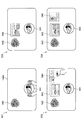
図19は、本実施形態に係る実オブジェクトの同定処理の一例を説明するための図である。図19では、朝の時間帯におけるUIの一例を示している。   FIG. 19 is a diagram for explaining an example of the real object identification process according to the present embodiment. FIG. 19 shows an example of a UI in the morning time zone.

符号411に示すように、まず、夫は自席に座ってコーヒーカップ421をテーブル140A上に置く。このコーヒーカップ421は、図16に示すようにエントリR3として実オブジェクトDBに登録されており、表5に示すようにエントリLE2においてテレビのアプリケーションと対応付けて対応関係DBに登録されている。このため、情報処理システム100は、エントリLE2を参照して、符号412に示すようにコーヒーカップ421から見て左側にテレビのアプリケーション422を起動する。   As indicated by reference numeral 411, the husband first sits at his seat and places the coffee cup 421 on the table 140A. The coffee cup 421 is registered in the real object DB as entry R3 as shown in FIG. 16, and is registered in the correspondence DB in association with the television application in entry LE2 as shown in Table 5. Therefore, the information processing system 100 refers to the entry LE2 and activates the television application 422 on the left side when viewed from the coffee cup 421 as indicated by reference numeral 412.

次いで、符号413に示すように、妻が自席に座ってコーヒーカップ423をテーブル140A上に置く。このコーヒーカップ423は、図16に示すようにエントリR4として実オブジェクトDBに登録されており、表5に示すようにエントリLE5においてチラシのアプリケーションと対応付けて対応関係DBに登録されている。このため、情報処理システム100は、エントリLE5を参照して、符号414に示すようにコーヒーカップ423から見て左側にチラシのアプリケーション424を起動する。   Next, as indicated by reference numeral 413, the wife sits on her seat and places the coffee cup 423 on the table 140A. This coffee cup 423 is registered in the real object DB as entry R4 as shown in FIG. 16, and is registered in the correspondence DB in association with the application of the leaflet in entry LE5 as shown in Table 5. Therefore, the information processing system 100 refers to the entry LE5 and activates the leaflet application 424 on the left side as viewed from the coffee cup 423 as indicated by reference numeral 414.

このように、画像情報及び立体形状情報がほぼ同一と言える実オブジェクトであっても、情報処理システム100は、位置マップを用いて区別することが可能であり、それぞれ異なる表示オブジェクトを対応付けることも可能である。さらに、情報処理システム100は、実オブジェクトを基準とした相対的な位置に表示オブジェクトを表示するため、例えばユーザが右手でコーヒーを置いた場合にユーザの目の前にアプリケーションを起動することが可能である。   As described above, the information processing system 100 can discriminate using the position map even if the image information and the solid shape information are almost the same, and each display object can be associated with each other. It is. Further, since the information processing system 100 displays the display object at a relative position with respect to the real object, for example, when the user places coffee with the right hand, the application can be started in front of the user. It is.

ここで、テーブル140Aの上方から撮像するカメラでは、ユーザの顔を捉えることは困難であり、ユーザ認識は困難であるとも言える。しかしながら、図19に示した例のように、情報処理システム100は、位置マップによって夫と妻といったユーザを実質的に識別可能である。また、情報処理システム100は、同じユーザであっても時間帯が異なれば、同じコーヒーカップが同じ位置に置かれても、異なるアプリケーションを起動することが可能である。このように、情報処理システム100は、同じ実オブジェクトでも使い方が異なれば、その使い方に適した異なる表示オブジェクトを表示することができる。   Here, it can be said that it is difficult for a camera that captures an image from above the table 140A to capture the user's face and user recognition is difficult. However, as in the example illustrated in FIG. 19, the information processing system 100 can substantially identify users such as husband and wife by the position map. Further, the information processing system 100 can start different applications even if the same user has different time zones, even if the same coffee cup is placed at the same position. In this way, the information processing system 100 can display different display objects suitable for the usage if the usage is different even for the same real object.

(ローカルの対応関係DBに係る具体例)
続いて、図20及び図21を参照して、ローカルの対応関係DBへのエントリ登録に係る具体例を説明する。
(Specific example related to local correspondence DB)
Next, a specific example related to entry registration in the local correspondence DB will be described with reference to FIGS.

図20は、本実施形態に係るローカルの対応関係DBに関する処理の一例を説明するための図である。図20を参照して、表示オブジェクトと実オブジェクトとが初めて対応付けられる場合の例を説明する。   FIG. 20 is a diagram for explaining an example of processing related to the local correspondence DB according to the present embodiment. An example in which a display object and a real object are associated with each other for the first time will be described with reference to FIG.

符号431に示すように、ユーザがテーブル140A上でテレビのアプリケーション441を閲覧している。次いで、符号432に示すように、ユーザが、テレビのアプリケーション441から見て右にコーヒーカップ442を置いたとする。この場合、情報処理システム100は、対応関係DB更新処理を行って、上記表5に示すエントリLE2を登録する。なお、コーヒーカップ442から見ると、テレビのアプリケーション441は左に位置している。符号432に示した状態が複数回再現されると、エントリLE2の関連度がインクリメントされていき、閾値以上となる。すると、符号433に示すように、ユーザがコーヒーカップ442をテーブル140A上に置くと、情報処理システム100は、符号434に示すように、コーヒーカップ442から見て左側にテレビのアプリケーション44を自動的に起動する。
As indicated by reference numeral 431, the user is viewing the television application 441 on the table 140A. Next, as indicated by reference numeral 432, it is assumed that the user places a coffee cup 442 on the right as viewed from the television application 441. In this case, the information processing system 100 performs the correspondence DB update process to register the entry LE2 shown in Table 5 above. When viewed from the coffee cup 442, the television application 441 is located on the left. When the state indicated by reference numeral 432 is reproduced a plurality of times, the relevance of the entry LE2 is incremented and becomes equal to or greater than the threshold value. Then, automatic as shown in reference numeral 433, the user places a coffee cup 442 on the table 140A, the information processing system 100, as indicated by reference numeral 434, to the left as viewed from the coffee cup 442 the application 44 1 TV Start up automatically.

図21は、本実施形態に係るローカルの対応関係DBに関する処理の一例を説明するための図である。図21を参照して、表示オブジェクトと実オブジェクトとが初めて対応付けられる場合の例を説明する。   FIG. 21 is a diagram for explaining an example of processing related to the local correspondence DB according to the present embodiment. With reference to FIG. 21, an example in which a display object and a real object are associated with each other for the first time will be described.

符号451に示すように、ユーザは、テーブル140A上にカップ麺461を置いて、ランチャー462をタッチする。すると、符号452に示すように、アプリケーションの一覧463が表示され、ユーザはその中からタイマーのアプリケーション464をカップ麺461の右下にドラッグして起動する。そして、ユーザは、符号453に示すようにアプリケーションの一覧463を閉じて、符号454に示すようにタイマーのアプリケーション464を利用する。この場合、情報処理システム100は、対応関係DB更新処理を行って、上記表5に示すエントリLE1を登録する。これにより、情報処理システム100は、カップ麺が置かれると、その右下にタイマーのアプリケーションを自動的に起動する。逆に、情報処理システム100は、ユーザがタイマーのアプリケーションを起動すると、その左上にカップ麺を置くべきことを提案する情報や他のカップ麺の広告情報を表示してもよい。   As indicated by reference numeral 451, the user places the cup noodle 461 on the table 140A and touches the launcher 462. Then, as indicated by reference numeral 452, an application list 463 is displayed, and the user drags the timer application 464 to the lower right of the cup noodle 461 to activate it. Then, the user closes the application list 463 as indicated by reference numeral 453 and uses the timer application 464 as indicated by reference numeral 454. In this case, the information processing system 100 performs the correspondence DB update process and registers the entry LE1 shown in Table 5 above. As a result, when the cup noodle is placed, the information processing system 100 automatically starts a timer application at the lower right. Conversely, when the user activates the timer application, the information processing system 100 may display information suggesting that cup noodles should be placed on the upper left and advertisement information of other cup noodles.

(クラウド上の対応関係DBに係る具体例)
続いて、図22〜図25を参照して、クラウド上の対応関係DBを参照した提供情報の表示に係る具体例を説明する。
(Specific examples related to the correspondence DB on the cloud)
Next, with reference to FIGS. 22 to 25, a specific example related to the display of the provided information with reference to the correspondence DB on the cloud will be described.

図22は、本実施形態に係るクラウド上の対応関係DBに関する処理の一例を説明するための図である。図22を参照して、クラウド上の対応関係DBに基づく提供情報が表示される場合の例を説明する。   FIG. 22 is a diagram for explaining an example of processing related to the correspondence DB on the cloud according to the present embodiment. With reference to FIG. 22, an example in which provided information based on the correspondence DB on the cloud is displayed will be described.

符号471に示すように、ユーザは、テーブル140A上にカップ麺481を置く。すると、情報処理システム100は、上記表5に示すエントリLE1を参照して、符号472に示すようにカップ麺481の右下にタイマーのアプリケーション482を起動する。そして、情報処理システム100は、上記表6に示すクラウド上の対応関係DBに登録されたエントリCE1を参照して、符号473に示すようにニュースのアプリケーションを起動するよう提案する半透明の表示オブジェクト483を表示する。符号473に示すように、ユーザが半透明の表示オブジェクト483をタッチして提案を受け入れると、情報処理システム100は、符号474に示すようにニュースのアプリケーション484を表示する。さらに、情報処理システム100は、カップ麺481とニュースのアプリケーション484を対応付ける対応関係情報を、ローカルの対応関係DBに登録してもよい。   As indicated by reference numeral 471, the user places the cup noodle 481 on the table 140A. Then, the information processing system 100 refers to the entry LE1 shown in Table 5 above and starts the timer application 482 at the lower right of the cup noodle 481 as indicated by reference numeral 472. Then, the information processing system 100 refers to the entry CE1 registered in the correspondence DB on the cloud shown in Table 6 above, and suggests launching the news application as indicated by reference numeral 473. 483 is displayed. As indicated by reference numeral 473, when the user touches the translucent display object 483 and accepts the proposal, the information processing system 100 displays the news application 484 as indicated by reference numeral 474. Further, the information processing system 100 may register correspondence information that associates the cup noodle 481 with the news application 484 in the local correspondence DB.

図23は、本実施形態に係るクラウド上の対応関係DBに関する処理の一例を説明するための図である。図23を参照して、クラウド上の対応関係DBに基づく提供情報が表示される場合の例を説明する。   FIG. 23 is a diagram for explaining an example of processing related to the correspondence DB on the cloud according to the present embodiment. With reference to FIG. 23, an example in which provided information based on the correspondence DB on the cloud is displayed will be described.

符号491に示すように、ユーザは、テーブル140A上にコーヒーカップ501を置いてテレビのアプリケーション502を閲覧している。すると、情報処理システム100は、上記表6に示すクラウド上の対応関係DBに登録されたエントリCE2を参照して、符号492に示すようにカレンダーのアプリケーションを起動するよう提案する半透明の表示オブジェクト503を表示する。符号493に示すように、ユーザが半透明の表示オブジェクト503をタッチして提案を受け入れると、情報処理システム100は、符号494に示すようにカレンダーのアプリケーション504を表示する。さらに、情報処理システム100は、コーヒーカップ501とカレンダーのアプリケーション504を対応付ける対応関係情報を、ローカルの対応関係DBに登録してもよい。   As indicated by reference numeral 491, the user places the coffee cup 501 on the table 140A and browses the television application 502. Then, the information processing system 100 refers to the entry CE2 registered in the correspondence DB on the cloud shown in Table 6 above, and proposes a semi-transparent display object to start the calendar application as indicated by reference numeral 492 503 is displayed. As indicated by reference numeral 493, when the user touches the translucent display object 503 and accepts the proposal, the information processing system 100 displays a calendar application 504 as indicated by reference numeral 494. Further, the information processing system 100 may register correspondence information that associates the coffee cup 501 with the calendar application 504 in the local correspondence DB.

図24は、本実施形態に係るクラウド上の対応関係DBに関する処理の一例を説明するための図である。図24を参照して、クラウド上の対応関係DBに基づく提供情報が表示される場合の例を説明する。   FIG. 24 is a diagram for explaining an example of processing related to the correspondence DB on the cloud according to the present embodiment. With reference to FIG. 24, an example in which provided information based on the correspondence DB on the cloud is displayed will be described.

符号511に示すように、ユーザは、テーブル140A上にティーカップ521及びティーポット522を置く。すると、情報処理システム100は、上記表5に示すローカルの対応関係DBに登録されたエントリLE3及びLE4を参照して、符号512に示すようにタイマーのアプリケーション523を起動する。そして、情報処理システム100は、上記表6に示すクラウド上の対応関係DBに登録されたエントリCE3を参照して、符号513に示すようにラジオのアプリケーションを起動するよう提案する半透明の表示オブジェクト524を表示する。符号513に示すように、ユーザが半透明の表示オブジェクト524をタッチして提案を受け入れると、情報処理システム100は、符号514に示すようにラジオのアプリケーション525を表示する。さらに、情報処理システム100は、ティーカップ521及び/又はティーポット522とラジオのアプリケーション525を対応付ける対応関係情報を、ローカルの対応関係DBに登録してもよい。   As indicated by reference numeral 511, the user places a tea cup 521 and a teapot 522 on the table 140A. Then, the information processing system 100 refers to the entries LE3 and LE4 registered in the local correspondence DB shown in Table 5 and starts the timer application 523 as indicated by reference numeral 512. Then, the information processing system 100 refers to the entry CE3 registered in the correspondence DB on the cloud shown in Table 6 above, and proposes a translucent display object that proposes to start a radio application as indicated by reference numeral 513 524 is displayed. As indicated by reference numeral 513, when the user touches the translucent display object 524 and accepts the proposal, the information processing system 100 displays a radio application 525 as indicated by reference numeral 514. Furthermore, the information processing system 100 may register correspondence information that associates the tea cup 521 and / or the teapot 522 with the radio application 525 in the local correspondence DB.

図25は、本実施形態に係るクラウド上の対応関係DBに関する処理の一例を説明するための図である。図25を参照して、クラウド上の対応関係DBに基づく提供情報が表示される場合の例を説明する。   FIG. 25 is a diagram for explaining an example of processing related to the correspondence DB on the cloud according to the present embodiment. With reference to FIG. 25, an example in which provided information based on the correspondence DB on the cloud is displayed will be described.

符号531に示すように、ユーザは、花542が飾られたテーブル140A上に洋食541を置く。すると、情報処理システム100は、上記表5に示すエントリLE6を参照して、符号532に示すようにレシピのアプリケーション543を起動する。なお、表6に示すように、クラウド上の対応関係DBにも、同様のエントリCE4が登録されている。しかし、情報処理システム100は、既にレシピのアプリケーション543を起動済みであるので、エントリCE4に基づく提案情報の表示は省略する。他方、情報処理システム100は、上記表6に示すクラウド上の対応関係DBに登録されたエントリCE5を参照して、符号533に示すようにカトラリーを推薦する表示オブジェクト544を表示する。符号533に示すように、ユーザがこの提案を気になってタッチすると、情報処理システム100は、符号534に示すようにカトラリーの購入サイトを表示するWebブラウザ545を起動する。   As indicated by reference numeral 531, the user places the Western food 541 on the table 140A on which the flowers 542 are decorated. Then, the information processing system 100 refers to the entry LE6 shown in Table 5 above and activates the recipe application 543 as indicated by reference numeral 532. As shown in Table 6, a similar entry CE4 is also registered in the correspondence DB on the cloud. However, since the information processing system 100 has already activated the recipe application 543, the display of the proposal information based on the entry CE4 is omitted. On the other hand, the information processing system 100 displays the display object 544 that recommends cutlery as indicated by reference numeral 533 with reference to the entry CE5 registered in the correspondence DB on the cloud shown in Table 6 above. As indicated by reference numeral 533, when the user cares about this proposal and touches it, the information processing system 100 activates a web browser 545 that displays a cutlery purchase site as indicated by reference numeral 534.

<<4.ハードウェア構成例>>
最後に、図26を参照して、本実施形態に係る情報処理装置のハードウェア構成について説明する。図26は、本実施形態に係る情報処理装置のハードウェア構成の一例を示すブロック図である。なお、図26に示す情報処理装置900は、例えば、図4に示した情報処理システム100、図5に示した入出力装置200及びサーバ300を実現し得る。本実施形態に係る情報処理システム100による情報処理は、ソフトウェアと、以下に説明するハードウェアとの協働により実現される。
<< 4. Hardware configuration example >>
Finally, with reference to FIG. 26, the hardware configuration of the information processing apparatus according to the present embodiment will be described. FIG. 26 is a block diagram illustrating an example of a hardware configuration of the information processing apparatus according to the present embodiment. 26 can realize, for example, the information processing system 100 illustrated in FIG. 4, the input / output device 200 and the server 300 illustrated in FIG. 5. Information processing by the information processing system 100 according to the present embodiment is realized by cooperation between software and hardware described below.

図26に示すように、情報処理装置900は、CPU(Central Processing Unit)901、ROM(Read Only Memory)902、RAM(Random Access Memory)903及びホストバス904aを備える。また、情報処理装置900は、ブリッジ904、外部バス904b、インタフェース905、入力装置906、出力装置907、ストレージ装置908、ドライブ909、接続ポート911及び通信装置913を備える。情報処理装置900は、CPU901に代えて、又はこれとともに、DSP若しくはASIC等の処理回路を有してもよい。   As shown in FIG. 26, the information processing apparatus 900 includes a CPU (Central Processing Unit) 901, a ROM (Read Only Memory) 902, a RAM (Random Access Memory) 903, and a host bus 904a. The information processing apparatus 900 includes a bridge 904, an external bus 904b, an interface 905, an input device 906, an output device 907, a storage device 908, a drive 909, a connection port 911, and a communication device 913. The information processing apparatus 900 may include a processing circuit such as a DSP or an ASIC in place of or in addition to the CPU 901.

CPU901は、演算処理装置および制御装置として機能し、各種プログラムに従って情報処理装置900内の動作全般を制御する。また、CPU901は、マイクロプロセッサであってもよい。ROM902は、CPU901が使用するプログラムや演算パラメータ等を記憶する。RAM903は、CPU901の実行において使用するプログラムや、その実行において適宜変化するパラメータ等を一時記憶する。CPU901は、例えば、図4及び図5に示す認識部122、記憶制御部124及び表示制御部126を形成し得る。   The CPU 901 functions as an arithmetic processing device and a control device, and controls the overall operation in the information processing device 900 according to various programs. Further, the CPU 901 may be a microprocessor. The ROM 902 stores programs used by the CPU 901, calculation parameters, and the like. The RAM 903 temporarily stores programs used in the execution of the CPU 901, parameters that change as appropriate during the execution, and the like. The CPU 901 can form, for example, the recognition unit 122, the storage control unit 124, and the display control unit 126 shown in FIGS.

CPU901、ROM902及びRAM903は、CPUバスなどを含むホストバス904aにより相互に接続されている。ホストバス904aは、ブリッジ904を介して、PCI(Peripheral Component Interconnect/Interface)バスなどの外部バス904bに接続されている。なお、必ずしもホストバス904a、ブリッジ904および外部バス904bを分離構成する必要はなく、1つのバスにこれらの機能を実装してもよい。   The CPU 901, ROM 902 and RAM 903 are connected to each other by a host bus 904a including a CPU bus. The host bus 904a is connected to an external bus 904b such as a PCI (Peripheral Component Interconnect / Interface) bus via a bridge 904. Note that the host bus 904a, the bridge 904, and the external bus 904b do not necessarily have to be configured separately, and these functions may be mounted on one bus.

入力装置906は、例えば、マウス、キーボード、タッチパネル、ボタン、マイクロフォン、スイッチ及びレバー等、ユーザによって情報が入力される装置によって実現される。また、入力装置906は、例えば、赤外線やその他の電波を利用したリモートコントロール装置であってもよいし、情報処理装置900の操作に対応した携帯電話やPDA等の外部接続機器であってもよい。他にも、入力装置906は、可視光カメラ、赤外線カメラ、ステレオカメラ、time of flight方式の測距センサ、structured light方式の測距センサ、生体センサ等であってもよい。さらに、入力装置906は、例えば、上記の入力手段を用いてユーザにより入力された情報に基づいて入力信号を生成し、CPU901に出力する入力制御回路などを含んでいてもよい。情報処理装置900のユーザは、この入力装置906を操作することにより、情報処理装置900に対して各種のデータを入力したり処理動作を指示したりすることができる。入力装置906は、例えば、図4及び図5に示す入力部110を形成し得る。   The input device 906 is realized by a device to which information is input by a user, such as a mouse, a keyboard, a touch panel, a button, a microphone, a switch, and a lever. The input device 906 may be, for example, a remote control device using infrared rays or other radio waves, or may be an external connection device such as a mobile phone or a PDA that supports the operation of the information processing device 900. . In addition, the input device 906 may be a visible light camera, an infrared camera, a stereo camera, a time of flight range sensor, a structured light range sensor, a biological sensor, or the like. Furthermore, the input device 906 may include, for example, an input control circuit that generates an input signal based on information input by the user using the above-described input means and outputs the input signal to the CPU 901. A user of the information processing apparatus 900 can input various data and instruct a processing operation to the information processing apparatus 900 by operating the input device 906. The input device 906 can form, for example, the input unit 110 illustrated in FIGS. 4 and 5.

出力装置907は、取得した情報をユーザに対して視覚的又は聴覚的に通知することが可能な装置で形成される。このような装置として、プロジェクタ、CRTディスプレイ装置、液晶ディスプレイ装置、プラズマディスプレイ装置、ELディスプレイ装置及びランプ等の表示装置や、スピーカ及びヘッドホン等の音声出力装置や、プリンタ装置等がある。出力装置907は、例えば、情報処理装置900が行った各種処理により得られた結果を出力する。具体的には、表示装置は、情報処理装置900が行った各種処理により得られた結果を、テキスト、イメージ、表、グラフ等、様々な形式で視覚的に表示する。他方、音声出力装置は、再生された音声データや音響データ等からなるオーディオ信号をアナログ信号に変換して聴覚的に出力する。上記表示装置及び上記音声出力装置は、例えば、図4及び図5に示す出力部130を形成し得る。   The output device 907 is formed of a device capable of visually or audibly notifying acquired information to the user. Examples of such devices include projectors, CRT display devices, liquid crystal display devices, plasma display devices, EL display devices, display devices such as lamps, audio output devices such as speakers and headphones, printer devices, and the like. For example, the output device 907 outputs results obtained by various processes performed by the information processing device 900. Specifically, the display device visually displays results obtained by various processes performed by the information processing device 900 in various formats such as text, images, tables, and graphs. On the other hand, the audio output device converts an audio signal composed of reproduced audio data, acoustic data, and the like into an analog signal and outputs it aurally. The display device and the audio output device can form, for example, the output unit 130 shown in FIGS. 4 and 5.

ストレージ装置908は、情報処理装置900の記憶部の一例として形成されたデータ格納用の装置である。ストレージ装置908は、例えば、HDD等の磁気記憶デバイス、半導体記憶デバイス、光記憶デバイス又は光磁気記憶デバイス等により実現される。ストレージ装置908は、記憶媒体、記憶媒体にデータを記録する記録装置、記憶媒体からデータを読み出す読出し装置および記憶媒体に記録されたデータを削除する削除装置などを含んでもよい。このストレージ装置908は、CPU901が実行するプログラムや各種データ及び外部から取得した各種のデータ等を格納する。ストレージ装置908は、例えば、図4及び図5に示す記憶部150を形成し得る。
The storage device 908 is a data storage device formed as an example of a storage unit of the information processing device 900. The storage device 908 is, for example, magnetic recording 憶De vice such as a HDD, a semiconductor storage device, is implemented by an optical storage device, or magneto-optical storage device or the like. The storage device 908 may include a storage medium, a recording device that records data on the storage medium, a reading device that reads data from the storage medium, a deletion device that deletes data recorded on the storage medium, and the like. The storage device 908 stores programs executed by the CPU 901, various data, various data acquired from the outside, and the like. The storage apparatus 908 can form the storage unit 150 shown in FIGS. 4 and 5, for example.

ドライブ909は、記憶媒体用リーダライタであり、情報処理装置900に内蔵、あるいは外付けされる。ドライブ909は、装着されている磁気ディスク、光ディスク、光磁気ディスク、または半導体メモリ等のリムーバブル記憶媒体に記録されている情報を読み出して、RAM903に出力する。また、ドライブ909は、リムーバブル記憶媒体に情報を書き込むこともできる。   The drive 909 is a storage medium reader / writer, and is built in or externally attached to the information processing apparatus 900. The drive 909 reads information recorded on a removable storage medium such as a magnetic disk, an optical disk, a magneto-optical disk, or a semiconductor memory, and outputs the information to the RAM 903. The drive 909 can also write information on a removable storage medium.

接続ポート911は、外部機器と接続されるインタフェースであって、例えばUSB(Universal Serial Bus)などによりデータ伝送可能な外部機器との接続口である。   The connection port 911 is an interface connected to an external device, and is a connection port with an external device that can transmit data by USB (Universal Serial Bus), for example.

通信装置913は、例えば、ネットワーク920に接続するための通信デバイス等で形成された通信インタフェースである。通信装置913は、例えば、有線若しくは無線LAN(Local Area Network)、LTE(Long Term Evolution)、Bluetooth(登録商標)又はWUSB(Wireless USB)用の通信カード等である。また、通信装置913は、光通信用のルータ、ADSL(Asymmetric Digital Subscriber Line)用のルータ又は各種通信用のモデム等であってもよい。この通信装置913は、例えば、インターネットや他の通信機器との間で、例えばTCP/IP等の所定のプロトコルに則して信号等を送受信することができる。通信装置913は、例えば、図5に示す通信部160及び通信部170を形成し得る。   The communication device 913 is a communication interface formed by a communication device for connecting to the network 920, for example. The communication device 913 is, for example, a communication card for wired or wireless LAN (Local Area Network), LTE (Long Term Evolution), Bluetooth (registered trademark), or WUSB (Wireless USB). The communication device 913 may be a router for optical communication, a router for ADSL (Asymmetric Digital Subscriber Line), a modem for various communication, or the like. The communication device 913 can transmit and receive signals and the like according to a predetermined protocol such as TCP / IP, for example, with the Internet and other communication devices. The communication device 913 can form, for example, the communication unit 160 and the communication unit 170 illustrated in FIG.

なお、ネットワーク920は、ネットワーク920に接続されている装置から送信される情報の有線、または無線の伝送路である。例えば、ネットワーク920は、インターネット、電話回線網、衛星通信網などの公衆回線網や、Ethernet(登録商標)を含む各種のLAN(Local Area Network)、WAN(Wide Area Network)などを含んでもよい。また、ネットワーク920は、IP−VPN(Internet Protocol−Virtual Private Network)などの専用回線網を含んでもよい。   The network 920 is a wired or wireless transmission path for information transmitted from a device connected to the network 920. For example, the network 920 may include a public line network such as the Internet, a telephone line network, a satellite communication network, various local area networks (LANs) including the Ethernet (registered trademark), a wide area network (WAN), and the like. The network 920 may also include a dedicated line network such as an IP-VPN (Internet Protocol-Virtual Private Network).

以上、本実施形態に係る情報処理装置900の機能を実現可能なハードウェア構成の一例を示した。上記の各構成要素は、汎用的な部材を用いて実現されていてもよいし、各構成要素の機能に特化したハードウェアにより実現されていてもよい。従って、本実施形態を実施する時々の技術レベルに応じて、適宜、利用するハードウェア構成を変更することが可能である。   Heretofore, an example of the hardware configuration capable of realizing the functions of the information processing apparatus 900 according to the present embodiment has been shown. Each of the above components may be realized using a general-purpose member, or may be realized by hardware specialized for the function of each component. Therefore, it is possible to change the hardware configuration to be used as appropriate according to the technical level at the time of carrying out this embodiment.

なお、上述のような本実施形態に係る情報処理装置900の各機能を実現するためのコンピュータプログラムを作製し、PC等に実装することが可能である。また、このようなコンピュータプログラムが格納された、コンピュータで読み取り可能な記録媒体も提供することができる。記録媒体は、例えば、磁気ディスク、光ディスク、光磁気ディスク、フラッシュメモリ等である。また、上記のコンピュータプログラムは、記録媒体を用いずに、例えばネットワークを介して配信されてもよい。   Note that a computer program for realizing each function of the information processing apparatus 900 according to the present embodiment as described above can be produced and mounted on a PC or the like. In addition, a computer-readable recording medium storing such a computer program can be provided. The recording medium is, for example, a magnetic disk, an optical disk, a magneto-optical disk, a flash memory, or the like. Further, the above computer program may be distributed via a network, for example, without using a recording medium.

<<5.まとめ>>
以上、図1〜図26を参照して、本開示の一実施形態について詳細に説明した。上記説明したように、本実施形態に係る情報処理システム100は、表示オブジェクトと実オブジェクトとの対応関係を示す情報を記憶部から取得し、表示オブジェクトが表示される物体表面において認識された表示オブジェクト又は実オブジェクトの少なくともいずれかに対応する提供情報を、対応関係を示す情報に基づいて表示する。これにより、ユーザは、例えば表示されている表示オブジェクトに対応する実オブジェクトに関する情報の提供を受けたり、表示面上に置いている実オブジェクトに対応する表示オブジェクトに関する情報の提供を受けたりすることができる。例えば、ユーザが実オブジェクトを表示面上に置くだけで、関連度の高いアプリケーションが自動的に起動されるので、起動ステップを省略することができる。このようにして、ユーザの利便性が向上し得る。
<< 5. Summary >>
The embodiment of the present disclosure has been described in detail above with reference to FIGS. As described above, the information processing system 100 according to the present embodiment acquires information indicating a correspondence relationship between a display object and a real object from the storage unit, and recognizes the display object recognized on the surface of the object on which the display object is displayed. Alternatively, the provision information corresponding to at least one of the real objects is displayed based on the information indicating the correspondence relationship. Thereby, for example, the user may be provided with information on a real object corresponding to the displayed display object, or may be provided with information on a display object corresponding to the real object placed on the display surface. it can. For example, since the application having a high degree of association is automatically started only by the user placing a real object on the display surface, the starting step can be omitted. In this way, user convenience can be improved.

また、情報処理システム100は、実オブジェクトの撮像画像、立体形状情報、及び位置マップにより実オブジェクトを同定する。このため、情報処理システム100は、テクスチャがない実オブジェクト、見た目が同じで高さが異なる実オブジェクト、及び見た目も高さも同じだが使用位置が異なる実オブジェクトを、それぞれ識別することができる。また、情報処理システム100は、ユーザの上方から撮像するカメラを用いた画像認識では困難なユーザ認識を、位置マップを用いることで実質的に実現可能にする。即ち、情報処理システム100は、同じ実オブジェクトでも使い方が異なれば、異なる提供情報を表示可能である。また、情報処理システム100は、撮像画像、立体形状情報、及び位置マップを組み合わせて実オブジェクトを同定するため、撮像画像のみを用いた認識方法と比較して実オブジェクトの認識精度が向上し得る。また、情報処理システム100は、認識に用いる上記数式1に関し重み係数を制御することで、撮像画像、立体形状情報、及び位置マップの利用比率を利用環境に合わせて最適化することができる。上記に関し、上記特許文献1に開示された技術では、識別のために画像のみが用いられているため、テクスチャがない実オブジェクト、見た目が同じで高さが異なる実オブジェクト、及び見た目も高さも同じだが使用位置が異なる実オブジェクトを、それぞれ識別することは困難であった。   Further, the information processing system 100 identifies a real object based on a captured image of the real object, solid shape information, and a position map. Therefore, the information processing system 100 can identify a real object having no texture, a real object having the same appearance and different height, and a real object having the same appearance and height but different usage positions. In addition, the information processing system 100 can substantially realize user recognition, which is difficult with image recognition using a camera that captures an image from above the user, by using a position map. That is, the information processing system 100 can display different provided information even if the same real object is used differently. In addition, since the information processing system 100 identifies the real object by combining the captured image, the solid shape information, and the position map, the recognition accuracy of the real object can be improved compared to the recognition method using only the captured image. In addition, the information processing system 100 can optimize the use ratio of the captured image, the solid shape information, and the position map according to the use environment by controlling the weighting coefficient with respect to Equation 1 used for recognition. Regarding the above, in the technique disclosed in Patent Document 1, since only an image is used for identification, a real object without a texture, a real object with the same appearance and different height, and the same appearance and height However, it was difficult to identify each real object that has a different use position.

また、情報処理システム100は、対応関係情報が含む相対的な配置を示す情報に従って提供情報を表示する。これにより、情報処理システム100は、実オブジェクトから見て適切な配置で提供情報を表示したり、表示オブジェクトから見て適切な配置で提供情報を表示したりすることができる。   Further, the information processing system 100 displays the provided information according to information indicating a relative arrangement included in the correspondence information. Thereby, the information processing system 100 can display the provision information with an appropriate arrangement as viewed from the real object, or can display the provision information with an appropriate arrangement as viewed from the display object.

また、情報処理システム100は、認識された表示オブジェクト及び実オブジェクトの組み合わせを対応付けたエントリを、対応関係DBに記憶する。このため、ユーザが実オブジェクトと表示オブジェクトとの対応付けを意識していなくても、情報処理システム100はユーザの利用状況を学習し、確度の高い情報提示を行うことが可能である。上記に関し、上記特許文献1では、予め画像と対応付けられた情報が提示されることが開示されるだけであって、動的に対応関係を学習/更新する点については開示されていない。   In addition, the information processing system 100 stores an entry in which the combination of the recognized display object and real object is associated in the correspondence DB. For this reason, even if the user is not conscious of the association between the real object and the display object, the information processing system 100 can learn the usage status of the user and present information with high accuracy. With respect to the above, the above-mentioned Patent Document 1 only discloses that information associated with an image in advance is presented, and does not disclose the point of dynamically learning / updating the correspondence.

また、情報処理システム100は、認識された表示オブジェクト又は実オブジェクトの少なくともいずれかに対応付けられた、他の表示オブジェクト又は他の実オブジェクトに関する提供情報を表示し得る。例えば、情報処理システム100は、クラウド上の対応関係DBを参照することで、ユーザが知らないアプリケーションや、テーブル140Aの利用状況に合致した新たな商品を提案することができる。さらに、第三者は、広告情報をクラウド上の対応関係DBに登録することで、ユーザにアプリケーションや商品等を推薦し、顧客開拓を行うことができる。   In addition, the information processing system 100 can display provision information related to another display object or another real object associated with at least one of the recognized display object or real object. For example, the information processing system 100 can propose a new product that matches the application that the user does not know or the usage status of the table 140A by referring to the correspondence DB on the cloud. Furthermore, by registering advertisement information in the correspondence DB on the cloud, a third party can recommend applications, products, etc. to the user and cultivate customers.

以上、添付図面を参照しながら本開示の好適な実施形態について詳細に説明したが、本開示の技術的範囲はかかる例に限定されない。本開示の技術分野における通常の知識を有する者であれば、特許請求の範囲に記載された技術的思想の範疇内において、各種の変更例または修正例に想到し得ることは明らかであり、これらについても、当然に本開示の技術的範囲に属するものと了解される。   The preferred embodiments of the present disclosure have been described in detail above with reference to the accompanying drawings, but the technical scope of the present disclosure is not limited to such examples. It is obvious that a person having ordinary knowledge in the technical field of the present disclosure can come up with various changes or modifications within the scope of the technical idea described in the claims. Of course, it is understood that it belongs to the technical scope of the present disclosure.

例えば、上記実施形態では、情報処理システム100は、夫や妻といった固定的なユーザにより利用される例を主に説明したが、本技術はかかる例に限定されない。例えば、情報処理システム100は、レストランやカフェ等に設置され、不特定多数の顧客により使用されてもよい。その場合、例えば、情報処理システム100は、顧客が起動したアプリケーションに応じて食事メニューを推薦したり、顧客が飲むドリンクに応じた情報を表示したりしてもよい。   For example, in the above embodiment, the information processing system 100 has mainly been described as being used by a fixed user such as a husband or wife, but the present technology is not limited to such an example. For example, the information processing system 100 may be installed in a restaurant, a cafe, or the like and used by an unspecified number of customers. In this case, for example, the information processing system 100 may recommend a meal menu according to an application activated by the customer, or display information according to a drink that the customer drinks.

また、本明細書において説明した各装置は、単独の装置として実現されてもよく、一部または全部が別々の装置として実現されても良い。例えば、認識部122、記憶制御部124及び表示制御部126は、それぞれ別々の装置に備えられていてもよい。   In addition, each device described in this specification may be realized as a single device, or a part or all of the devices may be realized as separate devices. For example, the recognition unit 122, the storage control unit 124, and the display control unit 126 may be provided in separate devices.

また、上記実施形態では、認識部122が、表示オブジェクト及び実オブジェクトを認識する例を説明したが、本技術はかかる例に限定されない。例えば、表示オブジェクトを認識する第1の認識部と、実オブジェクトを認識する第2の認識部が、それぞれ設けられていてもよい。さらに、第1の認識部と第2の認識部とは、それぞれ別々の装置に備えられていてもよい。   Moreover, although the recognition part 122 demonstrated the example which recognizes a display object and a real object in the said embodiment, this technique is not limited to this example. For example, a first recognition unit for recognizing a display object and a second recognition unit for recognizing a real object may be provided. Furthermore, the first recognition unit and the second recognition unit may be provided in separate devices.

また、本明細書においてフローチャートを用いて説明した処理は、必ずしも図示された順序で実行されなくてもよい。いくつかの処理ステップは、並列的に実行されてもよい。また、追加的な処理ステップが採用されてもよく、一部の処理ステップが省略されてもよい。また、上記フローチャートは繰り返し実行されてもよく、終了割り込みによって随時処理が終了してもよい。   Further, the processing described with reference to the flowcharts in this specification may not necessarily be executed in the order shown. Some processing steps may be performed in parallel. Further, additional processing steps may be employed, and some processing steps may be omitted. Further, the flowchart may be repeatedly executed, and the process may be terminated as needed by an end interrupt.

また、本明細書に記載された効果は、あくまで説明的または例示的なものであって限定的ではない。つまり、本開示に係る技術は、上記の効果とともに、または上記の効果に代えて、本明細書の記載から当業者には明らかな他の効果を奏しうる。   Further, the effects described in the present specification are merely illustrative or exemplary and are not limited. That is, the technology according to the present disclosure can exhibit other effects that are apparent to those skilled in the art from the description of the present specification in addition to or instead of the above effects.

なお、以下のような構成も本開示の技術的範囲に属する。
(1)
表示オブジェクトが表示される物体表面における前記表示オブジェクト及び実オブジェクトの認識結果に基づいて、認識された前記表示オブジェクト又は前記実オブジェクトの少なくともいずれかに対応する提供情報を表示部に表示させる表示制御部、
を備える情報処理システム。
(2)
前記表示制御部は、認識された前記表示オブジェクト又は前記実オブジェクトの位置に基づいて前記提供情報を表示させる、前記(1)に記載の情報処理システム。
(3)
前記表示制御部は、認識された前記表示オブジェクト及び前記実オブジェクトの位置に基づいて前記提供情報を表示させる、前記(2)に記載の情報処理システム。
(4)
前記提供情報は、認識された前記表示オブジェクトの位置、又は前記実オブジェクトの位置に基づいて生成される、前記(1)〜(3)のいずれか一項に記載の情報処理システム。
(5)
前記提供情報は、認識された前記表示オブジェクトの位置、及び前記実オブジェクトの位置に基づいて決定される、前記(4)に記載の情報処理システム。
(6)
前記表示制御部は、前記表示オブジェクトと前記実オブジェクトとの対応関係を示す情報に基づいて前記提供情報を表示させる、前記(1)に記載の情報処理システム。
(7)
前記対応関係を示す情報は、前記実オブジェクトと前記表示オブジェクトとの相対的な配置を示す情報を含み、
前記表示制御部は、前記相対的な配置を示す情報に基づいて前記提供情報を表示させる、前記(6)に記載の情報処理システム。
(8)
前記情報処理システムは、前記対応関係を示す情報を記憶部から取得する記憶制御部をさらに備える、前記(6)又は(7)に記載の情報処理システム。
(9)
前記記憶制御部は、前記実オブジェクトの撮像画像、立体形状を示す情報、又は前記物体表面における位置を示す情報により前記実オブジェクトを同定する、前記(8)に記載の情報処理システム。
(10)
前記記憶制御部は、前記実オブジェクトが検出された時間帯を示す情報により前記実オブジェクトを同定する、前記(9)に記載の情報処理システム。
(11)
前記記憶制御部は、認識された前記表示オブジェクト及び前記実オブジェクトの組み合わせを対応付けた前記対応関係を示す情報を前記記憶部に記憶させる、前記(8)〜(10)のいずれか一項に記載の情報処理システム。
(12)
前記提供情報は、認識された前記実オブジェクトと前記対応関係を示す情報において対応付けられた前記表示オブジェクトに関する情報である、前記(6)〜(11)のいずれか一項に記載の情報処理システム。
(13)
前記提供情報は、認識された前記表示オブジェクトと前記対応関係を示す情報において対応付けられた前記表示オブジェクトに関する情報である、前記(6)〜(12)のいずれか一項に記載の情報処理システム。
(14)
前記表示制御部は、認識された回数が多い又は時間が長い前記表示オブジェクト及び前記実オブジェクトの組み合わせについての前記対応関係を示す情報に基づく前記提供情報を優先的に表示させる、前記(13)に記載の情報処理システム。
(15)
前記表示制御部は、前記実オブジェクト又は前記表示オブジェクトが認識されてから、指定されたタイムラグを設けて前記提供情報を表示させる、前記(1)〜(14)のいずれか一項に記載の情報処理システム。
(16)
前記表示制御部は、認識された前記表示オブジェクト又は前記実オブジェクトの少なくともいずれかに対応付けられた広告情報を表示させる、前記(1)〜(15)のいずれか一項に記載の情報処理システム。
(17)
前記表示制御部は、認識されたユーザの生体情報に応じた前記提供情報を表示させる、前記(1)〜(16)のいずれか一項に記載の情報処理システム。
(18)
前記表示制御部は、認識されたユーザの周辺の装置に応じた前記提供情報を表示させる、前記(1)〜(17)のいずれか一項に記載の情報処理システム。
(19)
表示オブジェクトが表示される物体表面における前記表示オブジェクト及び実オブジェクトの認識結果に基づいて、認識された前記表示オブジェクト又は前記実オブジェクトの少なくともいずれかに対応する提供情報を表示部に表示させるようプロセッサにより制御すること、
を含む情報処理方法。
(20)
コンピュータを、
表示オブジェクトが表示される物体表面における前記表示オブジェクト及び実オブジェクトの認識結果に基づいて、認識された前記表示オブジェクト又は前記実オブジェクトの少なくともいずれかに対応する提供情報を表示部に表示させる表示制御部、
として機能させるためのプログラム。
(21)
表示オブジェクトが表示される物体表面における前記表示オブジェクト及び実オブジェクトの認識結果に基づいて、認識された前記表示オブジェクト又は前記実オブジェクトの少なくともいずれかに対応する提供情報を表示部に表示させるための表示制御信号を生成する表示制御部と、
を備えるサーバ。
(22)
前記表示制御部は、他の情報処理システムにおける前記対応関係を示す情報に基づいて前記提供情報を表示させる、前記(6)〜(14)のいずれか一項に記載の情報処理システム。
(23)
前記表示制御部は、認識されたユーザと類似する他のユーザに関する前記対応関係を示す情報に基づいて前記提供情報を表示させる、前記(22)に記載の情報処理システム。
The following configurations also belong to the technical scope of the present disclosure.
(1)
A display control unit for displaying provided information corresponding to at least one of the recognized display object or the real object on the display unit based on the recognition result of the display object and the real object on the surface of the object on which the display object is displayed ,
An information processing system comprising:
(2)
The information processing system according to (1), wherein the display control unit displays the provision information based on the recognized position of the display object or the real object.
(3)
The information processing system according to (2), wherein the display control unit displays the provision information based on the recognized position of the display object and the real object.
(4)
The information processing system according to any one of (1) to (3), wherein the provided information is generated based on a recognized position of the display object or a position of the real object.
(5)
The information processing system according to (4), wherein the provision information is determined based on the recognized position of the display object and the position of the real object.
(6)
The information processing system according to (1), wherein the display control unit displays the provision information based on information indicating a correspondence relationship between the display object and the real object.
(7)
The information indicating the correspondence includes information indicating a relative arrangement of the real object and the display object,
The information processing system according to (6), wherein the display control unit displays the provided information based on information indicating the relative arrangement.
(8)
The information processing system according to (6) or (7), further including a storage control unit that acquires information indicating the correspondence from the storage unit.
(9)
The information storage system according to (8), wherein the storage control unit identifies the real object based on a captured image of the real object, information indicating a three-dimensional shape, or information indicating a position on the object surface.
(10)
The information processing system according to (9), wherein the storage control unit identifies the real object based on information indicating a time zone in which the real object is detected.
(11)
The storage control unit causes the storage unit to store information indicating the correspondence relationship in which the recognized combination of the display object and the real object is associated with any one of (8) to (10). The information processing system described.
(12)
The information processing system according to any one of (6) to (11), wherein the provided information is information relating to the display object associated with the recognized real object in the information indicating the correspondence relationship. .
(13)
The information processing system according to any one of (6) to (12), wherein the provided information is information regarding the display object associated with the recognized display object and information indicating the correspondence relationship. .
(14)
The display control unit preferentially displays the provision information based on information indicating the correspondence relationship between the combination of the display object and the real object that has been recognized many times or for a long time. The information processing system described.
(15)
The information according to any one of (1) to (14), wherein the display control unit displays the provided information with a specified time lag after the real object or the display object is recognized. Processing system.
(16)
The information processing system according to any one of (1) to (15), wherein the display control unit displays advertisement information associated with at least one of the recognized display object or the real object. .
(17)
The information processing system according to any one of (1) to (16), wherein the display control unit displays the provision information according to the recognized user's biological information.
(18)
The information processing system according to any one of (1) to (17), wherein the display control unit displays the provided information according to a recognized peripheral device of the user.
(19)
Based on the recognition result of the display object and the real object on the surface of the object on which the display object is displayed, the processor displays the provided information corresponding to at least one of the recognized display object or the real object on the display unit. Controlling,
An information processing method including:
(20)
Computer
A display control unit for displaying provided information corresponding to at least one of the recognized display object or the real object on the display unit based on the recognition result of the display object and the real object on the surface of the object on which the display object is displayed ,
Program to function as.
(21)
Display for displaying provided information corresponding to at least one of the recognized display object and the real object on the display unit based on the recognition result of the display object and the real object on the surface of the object on which the display object is displayed A display control unit for generating a control signal;
A server comprising
(22)
The information processing system according to any one of (6) to (14), wherein the display control unit displays the provided information based on information indicating the correspondence relationship in another information processing system.
(23)
The information processing system according to (22), wherein the display control unit displays the provision information based on information indicating the correspondence relationship with respect to another user similar to the recognized user.

100 情報処理システム
110 入力部
120 制御部
122 認識部
124 記憶制御部
126 表示制御部
130 出力部
140 テーブル
150 記憶部
160 通信部
170 通信部
200 入出力装置
300 サーバ
DESCRIPTION OF SYMBOLS 100 Information processing system 110 Input part 120 Control part 122 Recognition part 124 Storage control part 126 Display control part 130 Output part 140 Table 150 Storage part 160 Communication part 170 Communication part 200 I / O device 300 Server

Claims (19)

表示オブジェクトが表示される物体表面における前記表示オブジェクト及び実オブジェクトの認識結果に基づいて、認識された前記表示オブジェクト又は前記実オブジェクトの少なくともいずれかに対応する提供情報を表示部に表示させる表示制御部、
を備え
前記表示制御部は、認識された回数が多い又は時間が長い、前記実オブジェクト及び前記表示オブジェクトの組み合わせについての対応関係を示す情報に基づく前記提供情報を優先的に表示させる、
情報処理システム。
A display control unit for displaying provided information corresponding to at least one of the recognized display object or the real object on the display unit based on the recognition result of the display object and the real object on the surface of the object on which the display object is displayed ,
Equipped with a,
The display control unit preferentially displays the provision information based on information indicating a correspondence relationship between the combination of the real object and the display object, which has been recognized many times or is long.
Information processing system.
前記表示制御部は、前記実オブジェクト又は前記表示オブジェクトが認識されてから、指定されたタイムラグを設けて前記提供情報を表示させる、請求項1に記載の情報処理システム。 The information processing system according to claim 1, wherein the display control unit displays the provided information with a specified time lag after the real object or the display object is recognized. 前記表示制御部は、認識された前記表示オブジェクト又は前記実オブジェクトの位置に基づいて前記提供情報を表示させる、請求項1に記載の情報処理システム。   The information processing system according to claim 1, wherein the display control unit displays the provided information based on the recognized position of the display object or the real object. 前記表示制御部は、認識された前記表示オブジェクト及び前記実オブジェクトの位置に基づいて前記提供情報を表示させる、請求項に記載の情報処理システム。 The information processing system according to claim 3 , wherein the display control unit displays the provided information based on the recognized position of the display object and the real object. 前記提供情報は、認識された前記表示オブジェクトの位置、又は前記実オブジェクトの位置に基づいて生成される、請求項1〜のいずれか一項に記載の情報処理システム。 The information processing system according to any one of claims 1 to 4 , wherein the provided information is generated based on the recognized position of the display object or the position of the real object. 前記提供情報は、認識された前記表示オブジェクトの位置、及び前記実オブジェクトの位置に基づいて決定される、請求項に記載の情報処理システム。 The information processing system according to claim 5 , wherein the provision information is determined based on the recognized position of the display object and the position of the real object. 前記表示制御部は、前記表示オブジェクトと前記実オブジェクトとの対応関係を示す情報に基づいて前記提供情報を表示させる、請求項1に記載の情報処理システム。   The information processing system according to claim 1, wherein the display control unit displays the provision information based on information indicating a correspondence relationship between the display object and the real object. 前記対応関係を示す情報は、前記実オブジェクトと前記表示オブジェクトとの相対的な配置を示す情報を含み、
前記表示制御部は、前記相対的な配置を示す情報に基づいて前記提供情報を表示させる、請求項に記載の情報処理システム。
The information indicating the correspondence includes information indicating a relative arrangement of the real object and the display object,
The information processing system according to claim 7 , wherein the display control unit displays the provision information based on information indicating the relative arrangement.
前記情報処理システムは、前記対応関係を示す情報を記憶部から取得する記憶制御部をさらに備える、請求項又はに記載の情報処理システム。 The information processing system further comprises a storage control unit that acquires information indicating the correspondence relationship from the storage unit, the information processing system according to claim 7 or 8. 前記記憶制御部は、前記実オブジェクトの撮像画像、立体形状を示す情報、又は前記物体表面における位置を示す情報により前記実オブジェクトを同定する、請求項に記載の情報処理システム。 The information processing system according to claim 9 , wherein the storage control unit identifies the real object based on a captured image of the real object, information indicating a three-dimensional shape, or information indicating a position on the object surface. 前記記憶制御部は、前記実オブジェクトが検出された時間帯を示す情報により前記実オブジェクトを同定する、請求項10に記載の情報処理システム。 The information processing system according to claim 10 , wherein the storage control unit identifies the real object based on information indicating a time zone in which the real object is detected. 前記記憶制御部は、認識された前記表示オブジェクト及び前記実オブジェクトの組み合わせを対応付けた前記対応関係を示す情報を前記記憶部に記憶させる、請求項11のいずれか一項に記載の情報処理システム。 The information according to any one of claims 9 to 11 , wherein the storage control unit stores information indicating the correspondence relationship in which a combination of the recognized display object and the real object is associated with the storage unit. Processing system. 前記提供情報は、認識された前記実オブジェクトと前記対応関係を示す情報において対応付けられた前記表示オブジェクトに関する情報である、請求項12のいずれか一項に記載の情報処理システム。 The information processing system according to any one of claims 7 to 12 , wherein the provided information is information related to the display object associated with the recognized real object and information indicating the correspondence relationship. 前記提供情報は、認識された前記表示オブジェクトと前記対応関係を示す情報において対応付けられた前記表示オブジェクトに関する情報である、請求項13のいずれか一項に記載の情報処理システム。 The information processing system according to any one of claims 7 to 13 , wherein the provided information is information related to the display object associated with the recognized display object in the information indicating the correspondence relationship. 前記表示制御部は、認識された前記表示オブジェクト又は前記実オブジェクトの少なくともいずれかに対応付けられた広告情報を表示させる、請求項1〜14のいずれか一項に記載の情報処理システム。 The display controller, recognized the display object or the real object of displaying the advertisement information associated with the at least one information processing system according to any one of claims 1-14. 前記表示制御部は、認識されたユーザの生体情報に応じた前記提供情報を表示させる、請求項1〜15のいずれか一項に記載の情報処理システム。 The information processing system according to any one of claims 1 to 15 , wherein the display control unit displays the provided information corresponding to the recognized biological information of the user. 前記表示制御部は、認識されたユーザの周辺の装置に応じた前記提供情報を表示させる、請求項1〜16のいずれか一項に記載の情報処理システム。 The information processing system according to any one of claims 1 to 16 , wherein the display control unit displays the provided information according to a recognized peripheral device of the user. 表示オブジェクトが表示される物体表面における前記表示オブジェクト及び実オブジェクトの認識結果に基づいて、認識された前記表示オブジェクト又は前記実オブジェクトの少なくともいずれかに対応する提供情報を表示部に表示させるようプロセッサにより制御し、認識された回数が多い又は時間が長い、前記実オブジェクト及び前記表示オブジェクトの組み合わせについての対応関係を示す情報に基づく前記提供情報を優先的に表示させること、
を含む情報処理方法。
Based on the recognition result of the display object and the real object on the surface of the object on which the display object is displayed, the processor displays the provided information corresponding to at least one of the recognized display object or the real object on the display unit. Controlling and preferentially displaying the provided information based on information indicating a correspondence relationship between the combination of the real object and the display object, which has been recognized many times or for a long time ,
An information processing method including:
コンピュータを、
表示オブジェクトが表示される物体表面における前記表示オブジェクト及び実オブジェクトの認識結果に基づいて、認識された前記表示オブジェクト又は前記実オブジェクトの少なくともいずれかに対応する提供情報を表示部に表示させ、認識された回数が多い又は時間が長い、前記実オブジェクト及び前記表示オブジェクトの組み合わせについての対応関係を示す情報に基づく前記提供情報を優先的に表示させる表示制御部、
として機能させるためのプログラム。
Computer
Based on the recognition result of the display object and the real object on the surface of the object on which the display object is displayed, the provided information corresponding to at least one of the recognized display object or the real object is displayed on the display unit and recognized. and a large number of times or a long time, the real object and the display the display control section of the provided information based on the information indicating the correspondence between Ru is preferentially displayed for the combination of objects,
Program to function as.
JP2015073833A 2015-03-31 2015-03-31 Information processing system, information processing method, and program Active JP6586758B2 (en)

Priority Applications (6)

Application Number Priority Date Filing Date Title
JP2015073833A JP6586758B2 (en) 2015-03-31 2015-03-31 Information processing system, information processing method, and program
US15/541,576 US10423283B2 (en) 2015-03-31 2016-02-23 Information processing system, information processing method and program
PCT/JP2016/000952 WO2016157703A1 (en) 2015-03-31 2016-02-23 Information processing system, information processing method and program
CN201680017769.1A CN107407967B (en) 2015-03-31 2016-02-23 Information processing system, information processing method, and program
EP16711901.5A EP3278197B1 (en) 2015-03-31 2016-02-23 Information processing system, information processing method and program
US16/536,930 US20190369808A1 (en) 2015-03-31 2019-08-09 Information processing system, information processing method and program

Applications Claiming Priority (1)

Application Number Priority Date Filing Date Title
JP2015073833A JP6586758B2 (en) 2015-03-31 2015-03-31 Information processing system, information processing method, and program

Publications (3)

Publication Number Publication Date
JP2016194762A JP2016194762A (en) 2016-11-17
JP2016194762A5 JP2016194762A5 (en) 2018-04-05
JP6586758B2 true JP6586758B2 (en) 2019-10-09

Family

ID=55629075

Family Applications (1)

Application Number Title Priority Date Filing Date
JP2015073833A Active JP6586758B2 (en) 2015-03-31 2015-03-31 Information processing system, information processing method, and program

Country Status (5)

Country Link
US (2) US10423283B2 (en)
EP (1) EP3278197B1 (en)
JP (1) JP6586758B2 (en)
CN (1) CN107407967B (en)
WO (1) WO2016157703A1 (en)

Families Citing this family (16)

* Cited by examiner, † Cited by third party
Publication number Priority date Publication date Assignee Title
US10802495B2 (en) 2016-04-14 2020-10-13 Deka Products Limited Partnership User control device for a transporter
US10926756B2 (en) 2016-02-23 2021-02-23 Deka Products Limited Partnership Mobility device
US10908045B2 (en) 2016-02-23 2021-02-02 Deka Products Limited Partnership Mobility device
US10220843B2 (en) 2016-02-23 2019-03-05 Deka Products Limited Partnership Mobility device control system
US11399995B2 (en) 2016-02-23 2022-08-02 Deka Products Limited Partnership Mobility device
USD830386S1 (en) * 2016-09-30 2018-10-09 Deka Products Limited Partnership Computer display with transition screen
USD830384S1 (en) 2016-09-30 2018-10-09 Deka Products Limited Partnership Computer display with home screen
USD830385S1 (en) 2016-09-30 2018-10-09 Deka Products Limited Partnership Computer display with selection screen
US11086393B2 (en) 2016-12-27 2021-08-10 Sony Corporation Information processing device, information processing method, and computer program
WO2018150756A1 (en) * 2017-02-15 2018-08-23 ソニー株式会社 Information processing device, information processing method, and storage medium
JP6930601B2 (en) * 2017-12-01 2021-09-01 日本電気株式会社 Information processing device, display position adjustment method, and program
CA3106189A1 (en) 2018-06-07 2019-12-12 Deka Products Limited Partnership System and method for distributed utility service execution
US10986617B2 (en) * 2018-08-07 2021-04-20 FG Innovation Company Limited Method and apparatus for activating PUCCH spatial relation
JP2020140291A (en) 2019-02-27 2020-09-03 ソニー株式会社 Information processor, information processing method, and program
JP7456844B2 (en) 2020-05-13 2024-03-27 東芝ライフスタイル株式会社 information processing system
JP6931511B1 (en) * 2020-08-24 2021-09-08 Arithmer株式会社 Programs, information processing devices and information processing methods

Family Cites Families (23)

* Cited by examiner, † Cited by third party
Publication number Priority date Publication date Assignee Title
JP3743988B2 (en) 1995-12-22 2006-02-08 ソニー株式会社 Information retrieval system and method, and information terminal
JP2001297400A (en) * 2000-04-14 2001-10-26 Kubota Fudosan Kanteisho:Kk Information providing device and recording medium storing information providing program
JP2005044029A (en) * 2003-07-24 2005-02-17 Olympus Corp Information presentation method and information presentation system
US7379562B2 (en) * 2004-03-31 2008-05-27 Microsoft Corporation Determining connectedness and offset of 3D objects relative to an interactive surface
US7394459B2 (en) * 2004-04-29 2008-07-01 Microsoft Corporation Interaction between objects and a virtual environment display
US7397464B1 (en) * 2004-04-30 2008-07-08 Microsoft Corporation Associating application states with a physical object
JP2006003969A (en) * 2004-06-15 2006-01-05 Sony Corp Content presentation method and content presentation device
US7576725B2 (en) * 2004-10-19 2009-08-18 Microsoft Corporation Using clear-coded, see-through objects to manipulate virtual objects
US9292996B2 (en) * 2006-12-19 2016-03-22 Igt Distributed side wagering methods and systems
US9280776B2 (en) * 2007-01-05 2016-03-08 Microsoft Technology Licensing, Llc Delivering content based on physical object characteristics
US8902227B2 (en) * 2007-09-10 2014-12-02 Sony Computer Entertainment America Llc Selective interactive mapping of real-world objects to create interactive virtual-world objects
US8621491B2 (en) * 2008-04-25 2013-12-31 Microsoft Corporation Physical object visualization framework for computing device with interactive display
US8847739B2 (en) * 2008-08-04 2014-09-30 Microsoft Corporation Fusing RFID and vision for surface object tracking
US8069081B2 (en) * 2008-09-23 2011-11-29 Microsoft Corporation Targeted advertising using object identification
US8289288B2 (en) * 2009-01-15 2012-10-16 Microsoft Corporation Virtual object adjustment via physical object detection
US8570281B2 (en) 2009-06-25 2013-10-29 Ncr Corporation Method and apparatus for multi-touch surface interaction for a financial application within a bank branch
US9910866B2 (en) * 2010-06-30 2018-03-06 Nokia Technologies Oy Methods, apparatuses and computer program products for automatically generating suggested information layers in augmented reality
US9996241B2 (en) * 2011-10-11 2018-06-12 Microsoft Technology Licensing, Llc Interactive visualization of multiple software functionality content items
JP5814772B2 (en) * 2011-12-15 2015-11-17 ヤフー株式会社 Advertisement determination system, advertisement determination method and program
JP2014002605A (en) * 2012-06-19 2014-01-09 Sharp Corp Information presentation device, information presentation method, control program, and recording medium
US9361730B2 (en) * 2012-07-26 2016-06-07 Qualcomm Incorporated Interactions of tangible and augmented reality objects
US9965799B2 (en) * 2012-12-12 2018-05-08 Perch Interactive, Inc. Apparatus and method for interactive product displays
US9925456B1 (en) * 2014-04-24 2018-03-27 Hasbro, Inc. Single manipulatable physical and virtual game assembly

Also Published As

Publication number Publication date
WO2016157703A1 (en) 2016-10-06
US10423283B2 (en) 2019-09-24
US20170351383A1 (en) 2017-12-07
JP2016194762A (en) 2016-11-17
CN107407967A (en) 2017-11-28
EP3278197A1 (en) 2018-02-07
US20190369808A1 (en) 2019-12-05
EP3278197B1 (en) 2021-04-21
CN107407967B (en) 2021-02-19

Similar Documents

Publication Publication Date Title
JP6586758B2 (en) Information processing system, information processing method, and program
US20210232821A1 (en) Virtualization of Tangible Interface Objects
US20230343092A1 (en) Virtualization of Tangible Interface Objects
EP2869275B1 (en) Information processing device, information processing method, and program
US10438058B2 (en) Information processing apparatus, information processing method, and program
KR20230144042A (en) Extended Reality for Productivity
US20150020014A1 (en) Information processing apparatus, information processing method, and program
US10146316B2 (en) Method and apparatus for disambiguating a plurality of targets
US20190318168A1 (en) Scene classification
US10930249B2 (en) Information processor, information processing method, and recording medium
US10969924B2 (en) Information processing apparatus, method, and non-transitory computer readable medium that controls a representation of a user object in a virtual space
US20210019911A1 (en) Information processing device, information processing method, and recording medium
US20180196503A1 (en) Information processing device, information processing method, and program
US10037077B2 (en) Systems and methods of generating augmented reality experiences
US20190042188A1 (en) Information processing device, information processing method, and program
WO2022057407A1 (en) Widget dislay method and electronic device
CN102062946A (en) Spectacles-type display device with communication function
WO2018150756A1 (en) Information processing device, information processing method, and storage medium
WO2023064719A1 (en) User interactions with remote devices
CN107683499B (en) Information processing apparatus, information processing method, and non-transitory computer readable medium
US11086393B2 (en) Information processing device, information processing method, and computer program
Tafreshi et al. Automatic, Gestural, Voice, Positional, or Cross-Device Interaction? Comparing Interaction Methods to Indicate Topics of Interest to Public Displays.
US20150121307A1 (en) Information processing device, information processing method, and program
CN111093025B (en) Image processing method and electronic equipment
JP7363807B2 (en) Information processing device, information processing system, information processing method, and program

Legal Events

Date Code Title Description
A521 Request for written amendment filed

Free format text: JAPANESE INTERMEDIATE CODE: A523

Effective date: 20180215

A621 Written request for application examination

Free format text: JAPANESE INTERMEDIATE CODE: A621

Effective date: 20180215

RD04 Notification of resignation of power of attorney

Free format text: JAPANESE INTERMEDIATE CODE: A7424

Effective date: 20190208

RD03 Notification of appointment of power of attorney

Free format text: JAPANESE INTERMEDIATE CODE: A7423

Effective date: 20190214

RD04 Notification of resignation of power of attorney

Free format text: JAPANESE INTERMEDIATE CODE: A7424

Effective date: 20190222

A131 Notification of reasons for refusal

Free format text: JAPANESE INTERMEDIATE CODE: A131

Effective date: 20190409

RD02 Notification of acceptance of power of attorney

Free format text: JAPANESE INTERMEDIATE CODE: A7422

Effective date: 20190515

RD04 Notification of resignation of power of attorney

Free format text: JAPANESE INTERMEDIATE CODE: A7424

Effective date: 20190522

A521 Request for written amendment filed

Free format text: JAPANESE INTERMEDIATE CODE: A523

Effective date: 20190531

TRDD Decision of grant or rejection written
A01 Written decision to grant a patent or to grant a registration (utility model)

Free format text: JAPANESE INTERMEDIATE CODE: A01

Effective date: 20190813

A61 First payment of annual fees (during grant procedure)

Free format text: JAPANESE INTERMEDIATE CODE: A61

Effective date: 20190826

R151 Written notification of patent or utility model registration

Ref document number: 6586758

Country of ref document: JP

Free format text: JAPANESE INTERMEDIATE CODE: R151