JP6586341B2 - Electronic device, pen, and pen holding method - Google Patents
Electronic device, pen, and pen holding method Download PDFInfo
- Publication number
- JP6586341B2 JP6586341B2 JP2015196021A JP2015196021A JP6586341B2 JP 6586341 B2 JP6586341 B2 JP 6586341B2 JP 2015196021 A JP2015196021 A JP 2015196021A JP 2015196021 A JP2015196021 A JP 2015196021A JP 6586341 B2 JP6586341 B2 JP 6586341B2
- Authority
- JP
- Japan
- Prior art keywords
- pen
- housing
- insertion piece
- engagement hole
- input surface
- Prior art date
- Legal status (The legal status is an assumption and is not a legal conclusion. Google has not performed a legal analysis and makes no representation as to the accuracy of the status listed.)
- Active
Links
Images


Classifications
-
- G—PHYSICS
- G06—COMPUTING; CALCULATING OR COUNTING
- G06F—ELECTRIC DIGITAL DATA PROCESSING
- G06F3/00—Input arrangements for transferring data to be processed into a form capable of being handled by the computer; Output arrangements for transferring data from processing unit to output unit, e.g. interface arrangements
- G06F3/01—Input arrangements or combined input and output arrangements for interaction between user and computer
- G06F3/03—Arrangements for converting the position or the displacement of a member into a coded form
- G06F3/033—Pointing devices displaced or positioned by the user, e.g. mice, trackballs, pens or joysticks; Accessories therefor
- G06F3/0354—Pointing devices displaced or positioned by the user, e.g. mice, trackballs, pens or joysticks; Accessories therefor with detection of 2D relative movements between the device, or an operating part thereof, and a plane or surface, e.g. 2D mice, trackballs, pens or pucks
- G06F3/03545—Pens or stylus
-
- G—PHYSICS
- G06—COMPUTING; CALCULATING OR COUNTING
- G06F—ELECTRIC DIGITAL DATA PROCESSING
- G06F1/00—Details not covered by groups G06F3/00 - G06F13/00 and G06F21/00
- G06F1/16—Constructional details or arrangements
- G06F1/1601—Constructional details related to the housing of computer displays, e.g. of CRT monitors, of flat displays
- G06F1/1607—Arrangements to support accessories mechanically attached to the display housing
-
- G—PHYSICS
- G06—COMPUTING; CALCULATING OR COUNTING
- G06F—ELECTRIC DIGITAL DATA PROCESSING
- G06F2200/00—Indexing scheme relating to G06F1/04 - G06F1/32
- G06F2200/16—Indexing scheme relating to G06F1/16 - G06F1/18
- G06F2200/163—Indexing scheme relating to constructional details of the computer
- G06F2200/1632—Pen holder integrated in the computer
Landscapes
- Engineering & Computer Science (AREA)
- General Engineering & Computer Science (AREA)
- Theoretical Computer Science (AREA)
- Human Computer Interaction (AREA)
- Physics & Mathematics (AREA)
- General Physics & Mathematics (AREA)
- Computer Hardware Design (AREA)
- Telephone Set Structure (AREA)
- Casings For Electric Apparatus (AREA)
Description
本発明の実施形態は、タッチパネルのペンを保持可能な電子機器に関する。 Embodiments described herein relate generally to an electronic device capable of holding a touch panel pen.
タッチパネルを押圧して情報を入力するタッチペンを内部スペースに影響することなく収納できる本体を備えた電子機器がある。この電子機器は、ペン状の突起部を有した取付部材を装着するための凹部を本体の側部に有している。凹部の底部には装着穴が開口しており、取付部材には装着孔に着脱自在に係合する係合部が設けられている。 There is an electronic device including a main body that can store a touch pen that inputs information by pressing a touch panel without affecting an internal space. This electronic device has a recess on the side of the main body for mounting an attachment member having a pen-like protrusion. A mounting hole is opened at the bottom of the recess, and the mounting member is provided with an engaging portion that is detachably engaged with the mounting hole.
ところで、タッチパネルに対応したペンはペン先が導電性を有しているものがある。電子機器は、高機能化、薄型化、及び軽量化に伴い筐体内部の実装状態が高密度になってきており、筺体の内部に専用のペン収納部を配置することが難しい。筐体の外周部には、無線通信用のアンテナなどが内蔵されるため、導電性部品が含まれたペンをアンテナの近傍に配置したくない。 By the way, there is a pen corresponding to the touch panel in which the pen tip has conductivity. Electronic devices are becoming denser in the mounting state inside the housing with higher functionality, thinner and lighter, and it is difficult to dispose a dedicated pen storage portion inside the housing. Since a wireless communication antenna or the like is built in the outer periphery of the housing, it is not desirable to place a pen including conductive parts in the vicinity of the antenna.
そこで、本発明に係る一実施形態では、筐体の外周縁に内蔵されるアンテナに影響することなく入力装置の入力用のペンを保持できる電子機器、ペン、及びペンの保持方法を提供する。 Therefore, in one embodiment according to the present invention, an electronic apparatus, a pen, and a pen holding method that can hold an input pen of an input device without affecting an antenna built in an outer peripheral edge of a housing are provided.
本発明の一実施形態の電子機器は、筐体とペンとアンテナとを備える。筐体は、入力面と、この入力面の周囲に位置された外周縁と、前記入力面に沿う方向に前記外周縁に開口された係合孔と、を有している。ペンは、前記筐体の前記外周縁に沿って配置された状態で、前記係合孔に着脱自在に嵌合する合成樹脂製の挿入片を有し、前記入力面に対する入力操作に使用される。アンテナは、前記筐体の前記外周縁の内側に配置され、前記入力面を横切る方向に沿う前記挿入片の寸法よりも小さい距離で前記挿入片に隣接する。
前記挿入片は、胴部および先端部を有する。前記胴部は、前記ペンの胴部に取り付けられた保持具の基部から前記ペンの径方向に延びるとともに、前記筐体の前記外周縁に沿う方向の寸法が前記係合孔の開口寸法よりも小さい。前記先端部は、前記胴部に連続するとともに、前記入力面を横切る方向に沿う寸法が前記係合孔の開口寸法より大きい。
An electronic device according to an embodiment of the present invention includes a housing, a pen, and an antenna. The housing has an input surface, and an outer peripheral edge which is located around the input surface, and a engaging hole that is opened in the outer circumferential edge in a direction along the input surface. Pen, the state in which disposed along the outer periphery of the housing, an insertion piece of a synthetic resin to be fitted detachably to the engaging hole, is used for input operation on the input surface . Antenna, the disposed inside of the outer periphery of the housing, adjacent the insert at a distance less than the dimension of the insertion piece along a direction transverse to the input surface.
The insertion piece has a body portion and a tip portion. The body portion extends in a radial direction of the pen from a base portion of a holder attached to the body portion of the pen, and a dimension along the outer peripheral edge of the housing is larger than an opening dimension of the engagement hole. small. The distal end portion is continuous with the body portion, and a dimension along a direction crossing the input surface is larger than an opening dimension of the engagement hole.
本発明の一実施形態のペンは、入力装置を筐体に内蔵した電子機器に入力操作を行うためのペンであって、前記筐体の外周縁に前記入力装置の入力面に沿う方向に開口された係合孔に着脱自在に嵌合する合成樹脂製の挿入片を備えている。前記挿入片が前記係合孔に挿入された状態では、前記係合孔の近傍で前記筐体の内部に配置されたアンテナに隣接して前記入力面を横切る方向に沿う前記挿入片の寸法よりも小さい位置に前記挿入片が配置される。
前記挿入片は、胴部および先端部を有する。前記胴部は、前記ペンの胴部に取り付けられた保持具の基部から前記ペンの径方向に延びるとともに、前記筐体の前記外周縁に沿う方向の寸法が前記係合孔の開口寸法よりも小さい。前記先端部は、前記胴部に連続するとともに、前記入力面を横切る方向に沿う寸法が前記係合孔の開口寸法より大きい。
A pen according to an embodiment of the present invention is a pen for performing an input operation on an electronic device in which an input device is built in a housing, and is opened in a direction along an input surface of the input device on an outer peripheral edge of the housing. And a synthetic resin insertion piece that is detachably fitted into the engagement hole . In a state where the insertion piece is inserted into the engagement hole, the dimension of the insertion piece along the direction crossing the input surface adjacent to the antenna disposed in the housing in the vicinity of the engagement hole The insertion piece is arranged at a smaller position .
The insertion piece has a body portion and a tip portion. The body portion extends in a radial direction of the pen from a base portion of a holder attached to the body portion of the pen, and a dimension along the outer peripheral edge of the housing is larger than an opening dimension of the engagement hole. small. The distal end portion is continuous with the body portion, and a dimension along a direction crossing the input surface is larger than an opening dimension of the engagement hole.
本発明の一実施形態のペンの保持方法は、入力装置およびアンテナを筐体に内蔵した電子機器に入力操作を行うペンを前記筐体に取り付けておくためのペンの保持方法である。
前記筐体は、前記入力装置の入力面の周囲に位置された外周縁と、前記入力面に沿う方向に前記外周縁に開口された係合孔と、を有し、前記ペンは、前記係合孔に着脱自在に嵌合する合成樹脂製の挿入片を側部に有するとともに、前記挿入片は、前記係合孔に対し前記入力面を横切る方向に弾性変形して嵌合する先端部を有する。
前記挿入片の前記先端部が前記挿入片の厚みよりも小さい距離で前記アンテナに接近する位置まで前記挿入片を前記入力面に沿って前記係合孔に差し込むことで、前記ペンを前記筐体の外周縁に沿うように前記筐体に固定する。
One pen holding method embodiments of the present invention is a pen holding method for permanently installing pen for inputting operation input device and an antenna in an electronic device with a built-in housing to the housing.
Wherein the housing has a peripheral edge which is located around the input surface of the input device, and a engaging hole that is opened on the outer peripheral edge in a direction along the input surface, the pen, the engagement A synthetic resin insertion piece that fits detachably in the joint hole is provided on the side portion, and the insertion piece has a distal end portion that is elastically deformed in a direction crossing the input surface with respect to the engagement hole. Have.
By plugging into said engaging hole along the insert to the input face tip to a position closer to the antenna at a distance less than the thickness of the insertion piece of the insert, the casing of the pen It fixes to the said housing | casing along the outer periphery .
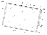
第1の実施形態に係る電子機器1について、図1から図4を参照して説明する。図1に示す電子機器1は、いわゆるタブレット型ポータブルコンピュータであって、四角形の平たいパネル状の筐体2の中にディスプレイユニット3、タッチ式の入力装置4、回路基板、バッテリ、及び通信用のアンテナ5を有している。ディスプレイユニット3の表示部31は、筐体2の一方の面に配置されている。
An electronic apparatus 1 according to the first embodiment will be described with reference to FIGS. An electronic apparatus 1 shown in FIG. 1 is a so-called tablet portable computer, and includes a display unit 3, a
入力装置4は、ディスプレイユニット3に重ねて配置されており、筐体2の表示部31側の面に利用者が指で触れたり、専用のペン6で触れたりすることによって、入力操作を行うことができる。つまり、表示部31が面した筐体2の外表面は、入力面41でもある。本実施形態の電子機器1は、入力装置4としてタッチパネルを備えており、繊細な入力操作を可能にするための専用のペン6が用いられる。ここで入力装置4としてのタッチパネルとは、感圧式タッチパネル、静電容量式タッチパネル、デジタイザなどの現在知られている方式に限らず、入力面に対してペン6を使って入力操作することができるものを含む。
The
アンテナ5は、周辺機器やインターネット等に無線接続するために使用される周波数帯に応じて個々に用意されており、筐体2の外周縁21に沿って配置されることが多い。なお、実施形態の説明の便宜上、入力操作される表示部側を「おもて面」、反対側の面を「裏面」と呼ぶ。また、表示部の1つの辺を上にした場合、その辺を「上部」、対辺を「下部」、左右の辺を「側部」と呼ぶことも有る。
The
ペン6は、ケースの中に電子回路、バッテリ、コイル等を内蔵しており、タッチパネルを内蔵した電子機器1の入力面41に対する入力操作をするための磁界をペン先6Aに発生する。このペン6は、使用しない場合、ペン先6Aにキャップ6Bが装着され、電子機器1の筐体2の外周縁21の1つの辺に沿って固定される。図1では、表示部31を横長の状態にして電子機器1を使用する一例を示しており、右の側部にペン6が保持されている。筐体2は、図2に示すように入力面41に沿う方向へ外周縁21に開口した係合孔22を有している。係合孔22は、外周縁21に沿う方向に長いスロット形状である。ペン6は、この筐体2の外周縁21に沿って配置された状態で係合孔22に着脱自在に嵌合する合成樹脂製の挿入片61を有している。係合孔22に対して挿入片61を入力面41に沿う方向に差し込むだけで簡単に固定される。
The
図3は、筐体の係合孔22にペン6の挿入片61が嵌合した状態で、筐体2側を入力面41に平行な面で切った断面図にして示す。図4は、係合孔22に挿入片61が嵌合した状態で、ペン6の中心軸に垂直な面で切った係合孔22及び挿入片61の断面図を示す。係合孔22及び挿入片61は、ペン6の太さよりも大きい長さを外周縁21に沿って有している。また、挿入片61は、入力面41を横切る方向へ係合孔22の開口寸法よりも大きい寸法の先端部62と、外周縁21に沿う方向に係合孔22の開口寸法よりも小さい寸法の胴部63とを有している。また、胴部63は、入力面41を横切る方向へ係合孔22の開口寸法とほぼ同じ寸法に形成される。
FIG. 3 is a sectional view in which the
本実施形態の場合、図2及び図3に示すように挿入片61は、ペン先6Aと反対側の端部6Cに外嵌する保持具60に一体に設けられている。保持具60は、外径がペン6の胴部と同じ太さに形成されたフープ形状の基部64を有している。したがって、基部64は、ペン6の端部6Cに設けられたくびれ部6Dに装着されている。挿入片61は、基部64からペン6の軸の半径方向に延びている。挿入片61の形状がこのように設定されることによって、ペン6は、挿入片61の差込方向を中心とした捩れのガタつきが抑えられ、外周縁21に沿った状態に保持される。
In the case of this embodiment, as shown in FIG.2 and FIG.3, the
アンテナ5は、入力面41を横切る方向の挿入片61の寸法よりも小さい距離に挿入片61に隣接するように係合孔22の近傍となる筐体2の外周縁21の内側に配置されている。本実施形態では図3及び図4に示すように、アンテナ5は、フィルム状の基板に対してパターン形成されたアンテナであって、入力面41を横切る方向へ挿入片61に少なくとも一部が重なる位置に配置される。なお、アンテナ5は、入力面41を横切る方向に挿入片61の寸法よりも小さい距離であれば、図3や図4のように挿入片61に重なる方向の他に外周縁21に沿う方向に並んで配置されていてもよい。
The
以上のように、入力装置4としてタッチパネルを筐体2に内蔵した電子機器1の入力面41に対する入力操作をするためのペン6を使用しない場合には、ペン6を筐体2に取り付けておく。本実施形態では、アンテナ5が内蔵された筐体2の外周縁21に、入力面41に沿う方向へ外周縁21に開口した係合孔22を設け、この係合孔22に着脱自在に嵌合する合成樹脂製の挿入片61をペン6の側部に設ける。挿入片61は、ペン6の軸方向に沿う係合孔22よりも小さく、入力面41を横切る方向に係合孔22に対して弾性変形して嵌合する厚みを有している。そして、挿入片61の厚みよりも小さい距離にアンテナ5に接近する位置まで入力面41に沿って外周縁21を横切る方向へ挿入片61を係合孔22に差し込むことで、ペン6を筐体2に着脱可能に固定する。
As described above, when the
挿入片61は、合成樹脂製であるので、このようにアンテナ5を接近して配置しても、アンテナ5の性能に影響しない。つまり、挿入片61が差し込まれる係合孔22に対してアンテナ5を離して配置する必要が無いため、筐体2内を有効に利用することができる。
Since the
以下に、第2から第5の実施形態の電子機器1について説明する。各実施形態において、第1の実施形態の電子機器1の構成と同じ機能を有する構成には、同じ符号を付し、詳細な説明は第1の実施形態の記載及び図を参酌することとする。 Below, the electronic device 1 of 2nd to 5th embodiment is demonstrated. In each embodiment, components having the same functions as those of the electronic device 1 of the first embodiment are denoted by the same reference numerals, and the detailed description refers to the description and drawings of the first embodiment. .
第2の実施形態の電子機器1について、図5を参照して説明する。図5は、電子機器1の外周縁21に設けられた係合孔22にペン6の挿入片61を差し込んでペン6を筐体2に保持した状態で、係合孔22及び挿入片61をその周辺部とともにペン6の中心軸に垂直な面で切った断面図である。図5に示すように、アンテナ5は、筐体2の外周縁21の内面に沿って湾曲して延びており、係合孔22を通って筐体2の中に延びた挿入片61が通される貫通穴51を有している。アンテナ5のパターンは、貫通穴51の周囲に形成される。貫通穴51である代わりに切欠であってもよい。この他の構成は、第1の実施形態の電子機器1と同じである。
An electronic apparatus 1 according to the second embodiment will be described with reference to FIG. 5 shows a state where the
以上のように構成された第2の実施形態の電子機器1によれば、アンテナ5を実装する範囲に重なるようにペン6の挿入片61を配置することができる。アンテナ5を配置する場合、導電性部品を含んだ周辺部品とは一定の距離を空ける必要があるため、筐体2の内部の実装効率を低下させるが、本実施形態のペン6の挿入片61は合成樹脂製であるので、アンテナ5の近傍に配置する際に位置的な制限を受けない。したがって、アンテナ5のパターンに空いている部分があれば、当該部分が係合孔22に合致するようにアンテナ5を配置することで、筐体2の内部の実装効率を高めることができる。
According to the electronic apparatus 1 of the second embodiment configured as described above, the
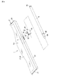
第3の実施形態の電子機器1について、図6を参照して説明する。図6は、電子機器1のペン6を取り外した状態の分解斜視図である。電子機器1において、筐体2は、係合孔22を外周縁21に沿って互いに離れた複数個所に有しており、ペン6は、この係合孔22に対応する間隔で離れた複数の挿入片61を有している。本実施形態の場合、電子機器1は、2つの係合孔22と、これに対応する2つの挿入片61を有している。ペン6は、入力操作の際に入力面41に当接するペン先6Aと、このペン先6Aを保護するキャップ6Bとを有している。挿入片61の1つは、ペン先6Aとは反対側の端部6Cに配置され、挿入片61のもう1つは、キャップ6Bに配置されている。したがって、挿入片61は、ペン6の両端に配置される。
An electronic apparatus 1 according to a third embodiment will be described with reference to FIG. FIG. 6 is an exploded perspective view of the electronic apparatus 1 with the
以上のように構成された第3の実施形態の電子機器1において、ペン6は、筐体2の2つの係合孔22に挿入片61がそれぞれ嵌合するので、ペン6を筐体2に固定して電子機器1を携行する場合に、ペン6が筐体2に対してしっかりと保持される。
In the electronic apparatus 1 according to the third embodiment configured as described above, the
第4の実施形態の電子機器1について、図7を参照して説明する。図7は、電子機器1のペン6を筐体2から取り外した状態の分解斜視図である。図7に示す電子機器1において、挿入片61は、ペン6の軸方向にほぼ中央の位置に配置されている。挿入片61は、他の実施形態と同様に、ペン6の軸から半径方向に突出している。ペン6を手に持つ場合、ペン6の軸方向に中央の範囲に突出するものが有ったとしても邪魔になることはない。本実施形態において、係合孔22は、ペン6が装着される外周縁21の端からペン6のキャップ6Bや端部6Cがはみ出さないように、ほぼ中央の位置に設けられる。
An electronic apparatus 1 according to a fourth embodiment will be described with reference to FIG. FIG. 7 is an exploded perspective view of the electronic device 1 with the
アンテナ5は、係合孔22が開口した筐体2の外周縁21の内面に沿って配置される。第1の実施形態のように係合孔22に嵌合した挿入片61に対して入力面41を横切る方向に重なるようにアンテナ5が配置されていてもよいし、第2の実施形態のように係合孔22に嵌合した挿入片61が差し込まれる貫通穴51を有していてもよい。
The
以上のように構成された第4の実施形態の電子機器1において、ペン6は、中央部に挿入片61が配置されているので、ペン先6Aが外周縁21に沿ってどちら向きになっても筐体2に対して装着することができる。また、挿入片61からペン6のキャップ6Bや端部6Cまでの距離が短いので、ペン6を筐体2に固定して電子機器1を携行する場合にペン6の安定性が増す。
In the electronic device 1 according to the fourth embodiment configured as described above, the
第5の実施形態の電子機器1について、図8を参照して説明する。本実施形態の電子機器1において、ペン6は、取り外し可能な保持具60を有し、挿入片61は、この保持具60に一体に設けられる。図8は、電子機器1のペン6を筐体2から取り外し、さらに保持具60からも抜き取った状態の分解斜視図である。保持具60は、ペン6の軸部の外径よりもやや小さい内径のフープ状の基部64を有している。この基部64は、挿入片61と一体につながる合成樹脂で作られており、ペン6の胴部に外嵌する弾性を有している。
An electronic apparatus 1 according to a fifth embodiment will be described with reference to FIG. In the electronic device 1 of the present embodiment, the
以上のように構成された第5の実施形態の電子機器1において、ペン6は、第4の実施形態と同様に中央部に挿入片61を配置することができるとともに、挿入片61の位置をペン6の軸方向に移動させることもできる。筐体2に対してペン6の配置を調整することができる。また、ペン6を他のものに取り換えることもできる。
In the electronic apparatus 1 according to the fifth embodiment configured as described above, the
なお、電子機器1は、表示面を有したタブレット型ポータブルコンピュータに限定されるものではなく、例えば、有線接続又は無線接続によって卓上コンピュータやクラムシェル型のポータブルコンピュータ、あるいはタブレット型ポータブルコンピュータなどの情報処理機器に拡張機能として外付け接続されるタッチパネルであってもよい。 The electronic device 1 is not limited to a tablet portable computer having a display surface. For example, information such as a desktop computer, a clamshell portable computer, or a tablet portable computer by wired connection or wireless connection is available. A touch panel externally connected to the processing device as an extended function may be used.
また、電子機器1の筐体2に対してペン6を保持する位置は、外周縁21のどの辺に沿っていてもよいし、電子機器1の使用状況に応じて、ペン6を保持する位置を変えられるように、に筐体2の外周縁21のうちの複数の辺に係合孔22を有していてもよい。さらに、第1の実施形態のようにペン先6Aの反対側の端部6Cでペン6が保持される場合、筐体2にペン6を取り付けた状態で電子機器1を操作するあるいは携行する間、ペン先6A側が動かないように、筐体2とペン6とを互いに内蔵した永久磁石などで吸着させてもよい。
In addition, the position where the
本発明のいくつかの実施形態を説明したが、これらの実施形態は、例として提示したものであり、発明の範囲を限定することを意図していない。これら新規な実施形態は、その他の様々な形態で実施されることが可能であり、発明の要旨を逸脱しない範囲で、種々の省略、置換え、変更を行うことができる。これら実施形態やその変形は、発明の範囲や要旨に含まれるとともに、特許請求の範囲に記載された発明とその均等の範囲に含まれる。 Although several embodiments of the present invention have been described, these embodiments are presented by way of example and are not intended to limit the scope of the invention. These novel embodiments can be implemented in various other forms, and various omissions, substitutions, and changes can be made without departing from the scope of the invention. These embodiments and modifications thereof are included in the scope and gist of the invention, and are included in the invention described in the claims and the equivalents thereof.
1…電子機器、2…筐体、21…外周縁、22…係合孔、4…入力装置(タッチパネル)、41…入力面、6…ペン、6A…ペン先、6B…キャップ、6C…端部、60…保持具、61…挿入片、62…先端部、63…胴部、64…基部。 DESCRIPTION OF SYMBOLS 1 ... Electronic device, 2 ... Housing | casing, 21 ... Outer periphery, 22 ... Engagement hole, 4 ... Input device (touch panel), 41 ... Input surface, 6 ... Pen, 6A ... Pen tip, 6B ... Cap, 6C ... End , 60 ... holder, 61 ... insert piece, 62 ... tip, 63 ... trunk, 64 ... base.
Claims (5)
前記筐体の前記外周縁に沿って配置された状態で、前記係合孔に着脱自在に嵌合する合成樹脂製の挿入片を有し、前記入力面に対する入力操作に使用されるペンと、
前記筐体の前記外周縁の内側に配置され、前記入力面を横切る方向に沿う前記挿入片の寸法よりも小さい距離で前記挿入片に隣接するアンテナと、
を備え、
前記挿入片は、
前記ペンの胴部に取り付けられた保持具の基部から前記ペンの径方向に延びるとともに、前記筐体の前記外周縁に沿う方向の寸法が前記係合孔の開口寸法よりも小さい胴部と、
前記胴部に連続するとともに、前記入力面を横切る方向に沿う寸法が前記係合孔の開口寸法より大きい先端部と、
を有する電子機器。 A housing having an input surface, an outer peripheral edge positioned around the input surface, and an engagement hole opened in the outer peripheral edge in a direction along the input surface ;
Wherein in a state in which the outer is peripheral arranged along the housing has the engagement hole to be fitted detachably synthetic resin insert strip, and a pen that is used to input operation to the input surface,
An antenna disposed inside the outer periphery of the housing and adjacent to the insertion piece at a distance smaller than the dimension of the insertion piece along the direction across the input surface;
Equipped with a,
The insertion piece is
A body part extending in a radial direction of the pen from a base part of a holder attached to the body part of the pen and having a dimension in a direction along the outer peripheral edge of the housing smaller than an opening dimension of the engagement hole;
A tip portion that is continuous with the body portion and that has a dimension along the direction crossing the input surface is larger than the opening size of the engagement hole;
Electronic equipment having
前記筐体の外周縁に前記入力装置の入力面に沿う方向に開口された係合孔に着脱自在に嵌合する合成樹脂製の挿入片を備え、前記挿入片が前記係合孔に挿入された状態では、前記係合孔の近傍で前記筐体の内部に配置されたアンテナに隣接して前記入力面を横切る方向に沿う前記挿入片の寸法よりも小さい位置に前記挿入片が配置され、
前記挿入片は、
前記ペンの胴部に取り付けられた保持具の基部から前記ペンの径方向に延びるとともに、前記筐体の前記外周縁に沿う方向の寸法が前記係合孔の開口寸法よりも小さい胴部と、
前記胴部に連続するとともに、前記入力面を横切る方向に沿う寸法が前記係合孔の開口寸法より大きい先端部と、
を有するペン。 A pen for performing an input operation on an electronic device with a built-in input device,
A synthetic resin insertion piece is provided in the outer peripheral edge of the housing so as to be detachably fitted in an engagement hole opened in a direction along the input surface of the input device, and the insertion piece is inserted into the engagement hole. In the state, the insertion piece is arranged at a position smaller than the dimension of the insertion piece along the direction crossing the input surface adjacent to the antenna arranged inside the housing in the vicinity of the engagement hole,
The insertion piece is
A body part extending in a radial direction of the pen from a base part of a holder attached to the body part of the pen and having a dimension in a direction along the outer peripheral edge of the housing smaller than an opening dimension of the engagement hole;
A tip portion that is continuous with the body portion and that has a dimension along the direction crossing the input surface is larger than the opening size of the engagement hole;
With pen.
前記筐体は、前記入力装置の入力面の周囲に位置された外周縁と、前記入力面に沿う方向に前記外周縁に開口された係合孔と、を有し、
前記ペンは、前記係合孔に着脱自在に嵌合する合成樹脂製の挿入片を側部に有するとともに、前記挿入片は、前記係合孔に対し前記入力面を横切る方向に弾性変形して嵌合する先端部を有し、
前記挿入片の前記先端部が前記挿入片の厚みよりも小さい距離で前記アンテナに接近する位置まで前記挿入片を前記入力面に沿って前記係合孔に差し込むことで、前記ペンを前記筐体の外周縁に沿うように前記筐体に固定するようにしたペンの保持方法。 A holding method of attaching an input device and a pen for performing an input operation to an electronic device having an antenna built in the housing to the housing,
The housing has an outer peripheral edge located around the input surface of the input device, and an engagement hole opened in the outer peripheral edge in a direction along the input surface,
The pen has a synthetic resin insertion piece detachably fitted in the engagement hole at a side portion, and the insertion piece is elastically deformed in a direction crossing the input surface with respect to the engagement hole. Having a tip to fit,
By inserting the insertion piece into the engagement hole along the input surface until the tip of the insertion piece approaches the antenna at a distance smaller than the thickness of the insertion piece, the pen is moved to the housing. A method of holding a pen that is fixed to the casing along the outer peripheral edge of the pen.
Priority Applications (2)
| Application Number | Priority Date | Filing Date | Title |
|---|---|---|---|
| JP2015196021A JP6586341B2 (en) | 2015-10-01 | 2015-10-01 | Electronic device, pen, and pen holding method |
| US15/279,206 US10198090B2 (en) | 2015-10-01 | 2016-09-28 | Electronic apparatus with touch screen, pen for touch screen and pen retention method |
Applications Claiming Priority (1)
| Application Number | Priority Date | Filing Date | Title |
|---|---|---|---|
| JP2015196021A JP6586341B2 (en) | 2015-10-01 | 2015-10-01 | Electronic device, pen, and pen holding method |
Publications (3)
| Publication Number | Publication Date |
|---|---|
| JP2017069867A JP2017069867A (en) | 2017-04-06 |
| JP2017069867A5 JP2017069867A5 (en) | 2018-10-25 |
| JP6586341B2 true JP6586341B2 (en) | 2019-10-02 |
Family
ID=58447848
Family Applications (1)
| Application Number | Title | Priority Date | Filing Date |
|---|---|---|---|
| JP2015196021A Active JP6586341B2 (en) | 2015-10-01 | 2015-10-01 | Electronic device, pen, and pen holding method |
Country Status (2)
| Country | Link |
|---|---|
| US (1) | US10198090B2 (en) |
| JP (1) | JP6586341B2 (en) |
Families Citing this family (38)
| Publication number | Priority date | Publication date | Assignee | Title |
|---|---|---|---|---|
| JP6586341B2 (en) * | 2015-10-01 | 2019-10-02 | Dynabook株式会社 | Electronic device, pen, and pen holding method |
| AU2016100745B4 (en) | 2016-05-24 | 2019-02-21 | Stm Management Pty Ltd | A case for a tablet shaped device and a method for making a case for a tablet shaped device. |
| US11320916B2 (en) * | 2016-07-22 | 2022-05-03 | Hewlett-Packard Development Company, L.P. | Pen holding devices |
| USD811409S1 (en) * | 2016-11-09 | 2018-02-27 | Getac Technology Corporation | Pen loop for mobile computer |
| USD878376S1 (en) | 2018-05-30 | 2020-03-17 | Google Llc | Convertible laptop computer |
| USD897346S1 (en) * | 2018-05-30 | 2020-09-29 | Google Llc | Stylus loop assembly including a stylus loop, stylus, and computer |
| USD887415S1 (en) | 2018-05-30 | 2020-06-16 | Google Llc | Adjustable folio |
| US11392171B2 (en) | 2018-08-21 | 2022-07-19 | Speculative Product Design, Llc | Holder for mobile electronic device |
| JP1651053S (en) * | 2019-02-25 | 2020-01-27 | ||
| WO2020222729A1 (en) * | 2019-04-29 | 2020-11-05 | Hewlett-Packard Development Company, L.P. | Device accessories with attachment slots |
| USD916708S1 (en) * | 2019-07-24 | 2021-04-20 | Huazhe Ke | Case for a tablet computer |
| US11714501B2 (en) | 2019-07-25 | 2023-08-01 | Hewlett-Packard Development Company, L.P. | Digital pen holder |
| USD900113S1 (en) * | 2019-07-30 | 2020-10-27 | Songshan PAN | Tablet case |
| USD928166S1 (en) * | 2019-08-19 | 2021-08-17 | Liangwu Hu | Tablet case |
| CN110727365B (en) * | 2019-09-17 | 2023-10-10 | 苏州佳世达电通有限公司 | Tool insertion structure and electronic device |
| USD906336S1 (en) * | 2019-12-12 | 2020-12-29 | Shenzhen Baishanchuan Technology Co., Ltd | Tablet case |
| USD886109S1 (en) * | 2019-12-18 | 2020-06-02 | Dongguan Gangyuan Technology Co., Ltd. | Protective case for tablet |
| USD906337S1 (en) * | 2019-12-26 | 2020-12-29 | Ganhua Cheng | Tablet case |
| US11275455B2 (en) | 2020-02-12 | 2022-03-15 | Apple Inc. | Mountable tool computer input |
| CN113381163B (en) * | 2020-02-25 | 2023-11-10 | 华为技术有限公司 | terminal |
| USD898035S1 (en) * | 2020-04-15 | 2020-10-06 | Ying Xu | Tablet case |
| KR20210142894A (en) * | 2020-05-19 | 2021-11-26 | 삼성전자주식회사 | Electronic device inlcuding pen input device |
| USD918924S1 (en) * | 2020-06-15 | 2021-05-11 | Ying Xu | Tablet case |
| USD943590S1 (en) * | 2020-06-26 | 2022-02-15 | Speculative Product Design, Llc | Electronic case with handle |
| USD931288S1 (en) * | 2020-07-23 | 2021-09-21 | Jiao Li | Protective cover for tablet |
| USD917493S1 (en) * | 2020-09-10 | 2021-04-27 | Hualin Zhang | Protective case for tablet PC with stand |
| JP2022074796A (en) * | 2020-11-05 | 2022-05-18 | レノボ・シンガポール・プライベート・リミテッド | Electronic device and information device system |
| WO2022103062A1 (en) * | 2020-11-10 | 2022-05-19 | 삼성전자 주식회사 | Electronic device comprising antenna and stylus pen |
| US11962711B2 (en) | 2020-11-10 | 2024-04-16 | Samsung Electronics Co., Ltd. | Electronic device including antenna and stylus pen |
| USD946578S1 (en) * | 2021-04-26 | 2022-03-22 | Ganhua Cheng | Tablet case |
| USD972574S1 (en) * | 2021-05-06 | 2022-12-13 | Dongguan Gangyuan Technology Co., Ltd. | Protective case for tablet |
| USD950566S1 (en) * | 2021-06-28 | 2022-05-03 | Huizhen Chen | Tablet cover |
| USD962949S1 (en) * | 2021-07-30 | 2022-09-06 | Zhaohong Xu | Portable electronic device case |
| USD956766S1 (en) * | 2021-08-06 | 2022-07-05 | Shenzhen Laudtec Electronics Co., Ltd. | Protective case for tablet computer |
| USD1023011S1 (en) * | 2021-08-11 | 2024-04-16 | Hai Wu | Mobile device case |
| US11324294B1 (en) * | 2021-10-29 | 2022-05-10 | Pioneer Square Brands, Inc. | Case for portable electronic computing device |
| USD1002622S1 (en) * | 2023-03-09 | 2023-10-24 | Shenzhen Zhexin Technology Co., Ltd. | Stylus for touch screens |
| USD995534S1 (en) * | 2023-04-24 | 2023-08-15 | Shilin Yu | Tablet computer case |
Family Cites Families (16)
| Publication number | Priority date | Publication date | Assignee | Title |
|---|---|---|---|---|
| JPH10187327A (en) | 1996-12-19 | 1998-07-14 | Seiko Instr Inc | Housing mechanism for input pen |
| JP2972702B2 (en) * | 1998-03-17 | 1999-11-08 | 静岡日本電気株式会社 | Pen input type portable information terminal |
| JP2001022509A (en) * | 1999-07-12 | 2001-01-26 | Sharp Corp | Input pen holding structure and information terminal device |
| JP2001142625A (en) * | 1999-11-16 | 2001-05-25 | Kenwood Corp | Electronic equipment |
| JP2002323952A (en) * | 2001-04-24 | 2002-11-08 | Kyocera Corp | Portable terminal equipment |
| TW537454U (en) * | 2002-05-14 | 2003-06-11 | High Tech Comp Corp | Stylus-accommodating structure for wireless communication apparatus |
| JP4462011B2 (en) * | 2004-11-01 | 2010-05-12 | 日本電気株式会社 | Mobile terminal device with TV function and TV antenna / input pen |
| KR100830218B1 (en) * | 2006-12-15 | 2008-05-16 | 세원텔레텍 주식회사 | Antenna with a stylus-pen |
| CN201509213U (en) * | 2009-08-11 | 2010-06-16 | 中兴通讯股份有限公司 | Mobile communication terminal and mobile communication terminal housing provided with antennae |
| KR101787750B1 (en) * | 2010-12-01 | 2017-10-19 | 삼성전자주식회사 | Capacitive stylus pen |
| US9268379B2 (en) * | 2012-07-27 | 2016-02-23 | Hewlett-Packard Development Company, L.P. | Stylus and holder device associated therewith |
| KR101940565B1 (en) * | 2012-08-02 | 2019-01-21 | 삼성전자주식회사 | Stylus pen and electronic device having the same |
| US9596914B2 (en) * | 2013-04-19 | 2017-03-21 | Joseph A. Zaloom | Tablet transformer |
| US10222879B2 (en) * | 2015-03-31 | 2019-03-05 | Microsoft Technology Licensing, Llc | Interlocking integrated battery structure for an electronic stylus |
| KR20170033633A (en) * | 2015-09-17 | 2017-03-27 | 삼성전자주식회사 | Pen and electronic device therewith |
| JP6586341B2 (en) * | 2015-10-01 | 2019-10-02 | Dynabook株式会社 | Electronic device, pen, and pen holding method |
-
2015
- 2015-10-01 JP JP2015196021A patent/JP6586341B2/en active Active
-
2016
- 2016-09-28 US US15/279,206 patent/US10198090B2/en active Active
Also Published As
| Publication number | Publication date |
|---|---|
| JP2017069867A (en) | 2017-04-06 |
| US10198090B2 (en) | 2019-02-05 |
| US20170097698A1 (en) | 2017-04-06 |
Similar Documents
| Publication | Publication Date | Title |
|---|---|---|
| JP6586341B2 (en) | Electronic device, pen, and pen holding method | |
| US20180083342A1 (en) | Wireless communication device having a slot antenna | |
| US20140028636A1 (en) | Multi-function stylus | |
| EP2662221A1 (en) | Writing instrument | |
| TW201530365A (en) | Active capacitive touch pen for providing an adjustable electromagnetic field | |
| KR102463499B1 (en) | Antenna and electronic device including the same | |
| JP5777122B2 (en) | Gesture input device | |
| US8542220B2 (en) | Electromagnetic stylus with auto-switching | |
| US11366532B2 (en) | Electronic device including antenna structure | |
| US9606642B2 (en) | Portable electronic device and miniaturization rechargeable capacitive stylus thereof | |
| JP5789560B2 (en) | Electronics | |
| US8382214B2 (en) | Case | |
| JP6125703B1 (en) | FIXED STRUCTURE AND INFORMATION PROCESSING SYSTEM HAVING THE SAME | |
| US10180737B2 (en) | Thin electromagnetic handwriting pen and method of manufacturing the same | |
| JP2007004592A (en) | Electronic equipment | |
| KR20110113801A (en) | Touch pen for multi-function | |
| KR101235119B1 (en) | Portable computer mouse with integrated palm rest | |
| US20110075383A1 (en) | Fixing structure | |
| US8358270B2 (en) | Mouse with wire arrangement structure | |
| TW202117507A (en) | Stylus structure | |
| JP2015125744A (en) | Position indicator | |
| JP6310231B2 (en) | Accessories-integrated housing | |
| TWM493095U (en) | Touch pen structure | |
| TWI793569B (en) | Touch pen structure and pen housing unit | |
| US9213868B2 (en) | Electronic device |
Legal Events
| Date | Code | Title | Description |
|---|---|---|---|
| A521 | Written amendment |
Free format text: JAPANESE INTERMEDIATE CODE: A523 Effective date: 20180913 |
|
| A621 | Written request for application examination |
Free format text: JAPANESE INTERMEDIATE CODE: A621 Effective date: 20180913 |
|
| A711 | Notification of change in applicant |
Free format text: JAPANESE INTERMEDIATE CODE: A712 Effective date: 20181206 |
|
| A711 | Notification of change in applicant |
Free format text: JAPANESE INTERMEDIATE CODE: A711 Effective date: 20181207 |
|
| A977 | Report on retrieval |
Free format text: JAPANESE INTERMEDIATE CODE: A971007 Effective date: 20190716 |
|
| TRDD | Decision of grant or rejection written | ||
| A01 | Written decision to grant a patent or to grant a registration (utility model) |
Free format text: JAPANESE INTERMEDIATE CODE: A01 Effective date: 20190820 |
|
| A61 | First payment of annual fees (during grant procedure) |
Free format text: JAPANESE INTERMEDIATE CODE: A61 Effective date: 20190909 |
|
| R150 | Certificate of patent or registration of utility model |
Ref document number: 6586341 Country of ref document: JP Free format text: JAPANESE INTERMEDIATE CODE: R150 |