JP6586183B2 - Frame synchronization apparatus, measurement apparatus including the same, frame synchronization method, and measurement method - Google Patents
Frame synchronization apparatus, measurement apparatus including the same, frame synchronization method, and measurement method Download PDFInfo
- Publication number
- JP6586183B2 JP6586183B2 JP2018038755A JP2018038755A JP6586183B2 JP 6586183 B2 JP6586183 B2 JP 6586183B2 JP 2018038755 A JP2018038755 A JP 2018038755A JP 2018038755 A JP2018038755 A JP 2018038755A JP 6586183 B2 JP6586183 B2 JP 6586183B2
- Authority
- JP
- Japan
- Prior art keywords
- data
- frame
- signal
- reference data
- head position
- Prior art date
- Legal status (The legal status is an assumption and is not a legal conclusion. Google has not performed a legal analysis and makes no representation as to the accuracy of the status listed.)
- Active
Links
Images


Landscapes
- Synchronisation In Digital Transmission Systems (AREA)
Description
本発明は、フレームの先頭位置を検出するフレーム同期装置及びそれを備えた測定装置並びにフレーム同期方法及び測定方法に関する。 The present invention relates to a frame synchronization apparatus that detects a head position of a frame, a measurement apparatus including the same, a frame synchronization method, and a measurement method.
従来、この種の装置は、入力信号においてフレームに含まれる既知のデータ列(同期ワード)を検出することにより、フレームの先頭位置を検出している。具体的には、同期ワードと同一のデータ列からなる参照データ列を予め用意し、入力信号において比較対象のデータ列を時間軸上で順次シフトさせて参照データ列と相関処理を行う(スライディング相関処理)。そして、相関値のピークを検出し、その相関ピークの位置に基づいてフレームの先頭位置を検出するようになっている(例えば、特許文献1参照)。 Conventionally, this type of apparatus detects the head position of a frame by detecting a known data string (synchronization word) included in the frame in an input signal. Specifically, a reference data sequence including the same data sequence as the synchronization word is prepared in advance, and the comparison target data sequence is sequentially shifted on the time axis in the input signal to perform correlation processing with the reference data sequence (sliding correlation). processing). Then, the peak of the correlation value is detected, and the head position of the frame is detected based on the position of the correlation peak (see, for example, Patent Document 1).
しかしながら、従来のスライディング相関処理では、信号品質が比較的悪い場合、例えば、信号対ノイズ比が比較的小さい場合や、周波数エラーが比較的大きい場合などに、相関ピークのパワーが減少して相関ピークが不明瞭になり易く、フレーム先頭位置を正確に検出できないことがあるという課題があった。 However, in the conventional sliding correlation processing, when the signal quality is relatively poor, for example, when the signal-to-noise ratio is relatively small, or when the frequency error is relatively large, the correlation peak power is reduced and the correlation peak is reduced. However, there is a problem that the frame head position may not be accurately detected.
本発明は、従来の課題を解決するためになされたものであり、信号品質が比較的悪い場合でも、フレーム先頭位置を正確に検出することができるフレーム同期装置及びそれを備えた測定装置並びにフレーム同期方法及び測定方法を提供することを目的とする。 The present invention has been made to solve the conventional problems, and is capable of accurately detecting the head position of a frame even when the signal quality is relatively poor, a measurement apparatus including the frame synchronization apparatus, and a frame. An object is to provide a synchronization method and a measurement method.
本発明の請求項1に係るフレーム同期装置は、入力信号(b)中に既知のデータ列(73)を含むフレーム(70)の先頭位置(71)を検出するフレーム同期装置(30)であって、前記既知のデータ列と同一の参照データ列(60)を記憶する記憶部(41)と、前記入力信号のうち、基準となる基準データを定めて前記基準データを所定のデータ間隔で順次シフトするシフト部(32)と、前記入力信号のうち前記基準データから前記参照データ列と同一サンプル数の範囲のデータ列と、前記参照データ列とにおける各先頭データから同一番目のデータ同士の複素共役積を算出して複素共役積データ列(80)を生成する生成部(42)と、前記複素共役積データ列のうち、先頭データから一の方向に所定サンプル数の範囲の先頭側データ領域(81)、及び前記複素共役積データ列のうち、末尾データから前記一の方向とは逆方向に前記所定サンプル数の範囲の末尾側データ領域(82)を設定する設定部(31)と、前記シフト部により前記基準データが定められるごとに、前記先頭側データ領域の各データと前記末尾側データ領域の各データとの間で相関演算を行って相関値を算出する算出部(44)と、前記相関値に基づいて前記フレームの前記先頭位置を検出する検出部(34)と、を備えた構成を有している。
The frame synchronizer according to
この構成により、本発明の請求項1に係るフレーム同期装置は、入力信号に含まれる所定サンプル数のデータ列と参照データ列とから複素共役積データ列を生成し、その先頭側データ領域の各データと末尾側データ領域の各データとの相関値に基づいて、フレームの先頭位置を検出している。このようにして得られた相関値は、周波数エラーの影響を受けにくく、ノイズに対する耐性も高い。したがって、本発明の請求項1に係るフレーム同期装置は、信号品質が比較的悪い場合でも、フレームの先頭位置を正確に検出することができる。
With this configuration, the frame synchronization apparatus according to
本発明の請求項2に係るフレーム同期装置では、前記シフト部は、第1のデータ間隔で前記基準データを順次シフトした後に、前記第1のデータ間隔よりも狭い第2のデータ間隔で前記基準データをシフトし、前記検出部は、前記第1のデータ間隔に基づいて前記フレームの前記先頭位置が含まれる先頭位置領域を推定し、推定した前記先頭位置領域において前記第2のデータ間隔に基づいて前記フレームの前記先頭位置を検出する構成を有している。 In the frame synchronizer according to claim 2 of the present invention, the shift unit sequentially shifts the reference data at a first data interval, and then the reference at a second data interval narrower than the first data interval. The data is shifted, and the detection unit estimates a head position area including the head position of the frame based on the first data interval, and based on the second data interval in the estimated head position area And detecting the head position of the frame.
この構成により、本発明の請求項2に係るフレーム同期装置は、フレーム先頭位置の検出処理の負荷を軽減するとともに、フレームの先頭位置を正確に検出することができる。 With this configuration, the frame synchronization apparatus according to claim 2 of the present invention can reduce the load of the frame head position detection process and can accurately detect the head position of the frame.
本発明の請求項3に係る測定装置は、請求項1又は請求項2に記載のフレーム同期装置(30)を備え、既知のデータ列を含むフレーム(70)を含んだ入力信号(a)の信号特性を測定する測定装置(10)であって、前記入力信号をベースバンド信号にダウンコンバートするダウンコンバータ(21)と、ダウンコンバートされた前記ベースバンド信号に含まれる前記フレームの先頭位置(71)を前記フレーム同期装置が検出した信号である検出信号(c)に基づいて、前記ベースバンド信号を復調して復調信号(d)を出力する復調信号出力部(51)と、出力された前記復調信号の信号特性を測定する測定部(12)と、を備えた構成を有している。
A measuring apparatus according to claim 3 of the present invention comprises the frame synchronizer (30) according to
この構成により、本発明の請求項3に係る測定装置は、フレーム同期装置を備えているので、信号品質が比較的悪い場合でも、フレーム先頭位置を正確に検出して所定の信号特性の測定を実施することができる。 With this configuration, since the measuring apparatus according to claim 3 of the present invention includes the frame synchronization apparatus, even when the signal quality is relatively poor, the frame head position is accurately detected and the predetermined signal characteristic is measured. Can be implemented.
本発明の請求項4に係るフレーム同期方法は、入力信号(b)中に既知のデータ列(73)を含むフレーム(70)の先頭位置(71)を検出するフレーム同期方法であって、前記既知のデータ列と同一の参照データ列(60)を記憶する記憶ステップ(S11)と、前記入力信号のうち、基準となる基準データを定めて前記基準データを所定のデータ間隔で順次シフトするシフトステップ(S15)と、前記入力信号のうち前記基準データから前記参照データ列と同一サンプル数の範囲のデータ列と、前記参照データ列とにおける各先頭データから同一番目のデータ同士の複素共役積を算出して複素共役積データ列(80)を生成する生成ステップ(S16)と、前記複素共役積データ列のうち、先頭データから一の方向に所定サンプル数の範囲の先頭側データ領域(81)、及び前記複素共役積データ列のうち、末尾データから前記一の方向とは逆方向に前記所定サンプル数の範囲の末尾側データ領域(82)を設定する設定ステップ(S17)と、前記シフトステップにより前記基準データが定められるごとに、前記先頭側データ領域の各データと前記末尾側データ領域の各データとの間で相関演算を行って相関値を算出する算出ステップ(S18)と、前記相関値に基づいて前記フレームの前記先頭位置を検出する検出ステップ(S22)と、を備えた構成を有している。 A frame synchronization method according to claim 4 of the present invention is a frame synchronization method for detecting a head position (71) of a frame (70) including a known data string (73) in an input signal (b), A storage step (S11) for storing the same reference data string (60) as a known data string, and a shift for determining reference data as a reference from the input signals and sequentially shifting the reference data at a predetermined data interval Step (S15), a complex conjugate product of the same number of data from the first data in the reference data string and a data string in the range of the same number of samples as the reference data string from the reference data in the input signal A generation step (S16) for generating a complex conjugate product data string (80) by calculation, and a predetermined number of samples in one direction from the top data in the complex conjugate product data string Setting for setting the end data area (82) of the predetermined number of samples in the direction opposite to the one direction from the end data in the start data area (81) of the range and the complex conjugate product data string Each time the reference data is determined by the step (S17) and the shift step, a correlation value is calculated by performing a correlation operation between each data in the head data area and each data in the tail data area. A calculation step (S18); and a detection step (S22) for detecting the head position of the frame based on the correlation value.
この構成により、本発明の請求項4に係るフレーム同期方法は、入力信号に含まれる所定サンプル数のデータ列と参照データ列とから複素共役積データ列を生成し、その先頭側データ領域の各データと末尾側データ領域の各データとの相関値に基づいて、フレームの先頭位置を検出している。このようにして得られた相関値は、周波数エラーの影響を受けにくく、ノイズに対する耐性も高い。したがって、本発明の請求項4に係るフレーム同期方法は、信号品質が比較的悪い場合でも、フレームの先頭位置を正確に検出することができる。 With this configuration, the frame synchronization method according to claim 4 of the present invention generates a complex conjugate product data sequence from a data sequence of a predetermined number of samples included in an input signal and a reference data sequence, and each of the head side data areas The start position of the frame is detected based on the correlation value between the data and each data in the end data area. The correlation value obtained in this way is not easily affected by frequency errors and has high resistance to noise. Therefore, the frame synchronization method according to claim 4 of the present invention can accurately detect the start position of the frame even when the signal quality is relatively poor.
本発明の請求項5に係る測定方法は、前記シフトステップでは、第1のデータ間隔で前記基準データを順次シフトした後に、前記第1のデータ間隔よりも狭い第2のデータ間隔で前記基準データをシフトし、前記検出ステップでは、前記第1のデータ間隔に基づいて前記フレームの前記先頭位置が含まれる先頭位置領域を推定し、推定した前記先頭位置領域において前記第2のデータ間隔に基づいて前記フレームの前記先頭位置を検出する構成を有している。
In the measurement method according to
この構成により、本発明の請求項5に係る測定方法は、フレーム先頭位置の検出処理の負荷を軽減するとともに、フレームの先頭位置を正確に検出することができる。 With this configuration, the measurement method according to the fifth aspect of the present invention can reduce the load of the frame head position detection process and accurately detect the head position of the frame.
本発明の請求項6に係る測定方法は、請求項4又は請求項5に記載のフレーム同期方法を備え、既知のデータ列を含むフレーム(70)を含んだ入力信号(a)の信号特性を測定する測定方法であって、前記入力信号をベースバンド信号にダウンコンバートするダウンコンバートステップ(S12)と、ダウンコンバートされた前記ベースバンド信号に含まれる前記フレームの先頭位置(71)を前記フレーム同期方法で検出した信号である検出信号(c)に基づいて、前記ベースバンド信号を復調して復調信号(d)を出力する復調信号出力ステップ(S23)と、出力された前記復調信号の信号特性を測定する測定ステップ(S24)と、を備えた構成を有している。 A measurement method according to a sixth aspect of the present invention includes the frame synchronization method according to the fourth or fifth aspect, wherein a signal characteristic of an input signal (a) including a frame (70) including a known data string is obtained. A measurement method for measuring, wherein a down-conversion step (S12) for down-converting the input signal into a baseband signal, and a start position (71) of the frame included in the down-converted baseband signal are synchronized with the frame. A demodulated signal output step (S23) for demodulating the baseband signal and outputting a demodulated signal (d) based on a detection signal (c) which is a signal detected by the method; and signal characteristics of the demodulated signal output And a measurement step (S24) for measuring.
この構成により、本発明の請求項6に係る測定方法は、フレーム同期方法を備えているので、信号品質が比較的悪い場合でも、フレーム先頭位置を正確に検出して所定の信号特性の測定を実施することができる。 With this configuration, the measurement method according to claim 6 of the present invention includes the frame synchronization method, so that even when the signal quality is relatively poor, the frame head position is accurately detected to measure a predetermined signal characteristic. Can be implemented.
本発明によれば、信号品質が比較的悪い場合でも、フレーム先頭位置を正確に検出することができるフレーム同期装置及びそれを備えた測定装置並びにフレーム同期方法及び測定方法を提供することができる。 According to the present invention, it is possible to provide a frame synchronization apparatus that can accurately detect a frame head position even when signal quality is relatively poor, a measurement apparatus including the frame synchronization apparatus, a frame synchronization method, and a measurement method.
本発明の実施形態について図面を参照して説明する。
以下では、例として、OFDM(Orthogonal Frequency Division Multiplexing:直交周波数分割多重)信号を出力する被測定装置(DUT)について、その信号特性を測定する測定装置を説明する。
Embodiments of the present invention will be described with reference to the drawings.
Hereinafter, as an example, a measurement apparatus that measures signal characteristics of a device under test (DUT) that outputs an Orthogonal Frequency Division Multiplexing (OFDM) signal will be described.
[測定装置]
図1に示すように、本実施形態の測定装置10は、DUT1から入力する入力信号aの信号特性を測定するものであり、受信部20、フレーム同期装置30、信号処理部50、及び表示部11を備えている。この入力信号aは、OFDM信号である。OFDM信号は、送信側(DUT1)で、フレーム内の時間軸上の所定の位置に既知のデータ列(同期ワード)を挿入したデータ系列に対し、OFDM変調、アップコンバート等を行って得られた信号である。
[measuring device]
As shown in FIG. 1, the
受信部20は、DUT1からアンテナを介して、或いは、有線で入力信号aを受信するものであり、ダウンコンバータ21、ADC(アナログ・デジタル変換器)22、及び直交復調部23を備えている。
The
ダウンコンバータ21は、DUT1から入力した入力信号aをベースバンドの信号に周波数変換し、ADC22に出力するようになっている。
The down-
ADC22は、ダウンコンバータ21が周波数変換した信号をサンプリングしてアナログ値からデジタル値に変換し、得られたデジタル変換信号を直交復調部23に出力するようになっている。
The
直交復調部23は、ADC22が出力したデジタル変換信号をI(同相)信号成分及びQ(直交)信号成分に直交復調し、得られた直交復調信号bをフレーム同期装置30及び信号処理部50に出力するようになっている。直交復調信号bは複素信号である。
The
フレーム同期装置30は、直交復調部23が出力した直交復調信号bに含まれるフレームの先頭位置を検出し、検出したことを示す検出信号cを信号処理部50に出力するようになっている。このフレーム同期装置30の詳細な構成については後述する。なお、直交復調信号bは、フレーム同期装置30の入力信号である。
The
信号処理部50は、受信部20が出力した直交復調信号bに各種デジタル信号処理を施し、入力信号aの信号特性を測定するものであり、OFDM復調部51及び測定部52を備えている。
The
OFDM復調部51は、直交復調部23が出力した直交復調信号bと、フレーム同期装置30が出力した検出信号cを入力するようになっている。そして、OFDM復調部51は、検出信号cに基づいて、直交復調信号bに対し、FFT(高速フーリエ変換)処理、サブキャリア復調などのOFDM復調処理を行って復調信号dを生成し、測定部52に出力するようになっている。なお、OFDM復調部51は、本発明の復調信号出力部の一例である。
The
測定部52は、OFDM復調部51が出力した復調信号dに対して、例えば、周波数エラー、タイミングエラー、EVM(Error Vector Magnitude)、送信パワー、コンスタレーション等を測定、解析するように構成されている。
The
表示部11は、測定部52により得られた測定結果のデータやグラフ等を表示するようになっている。
The
[フレーム同期装置]
次に、フレーム同期装置30の構成について説明する。
[Frame synchronization device]
Next, the configuration of the
フレーム同期装置30は、入力信号である直交復調信号bからフレームの先頭位置を検出するものであり、相関処理部40、データ領域設定部31、基準データシフト部32、閾値記憶部33、及び先頭位置検出部34を備えている。
The
相関処理部40は、受信部20で得られた複素データ系列である直交復調信号bとその理想信号との相関処理を行うものであり、参照データ列記憶部41、複素共役積データ列生成部42、及び相関値算出部44を備えている。
The
参照データ列記憶部41は、直交復調信号bにおいて送信側で挿入した同期ワードに対応する部分の理想的な既知のデータ列(参照データ列という)を格納するようになっている。参照データ列は、干渉やノイズの影響を受けていない理想的なデータ列である。なお、参照データ列記憶部41は、本発明の記憶部の一例である。
The reference data
基準データシフト部32は、直交復調信号bに含まれる複素データ系列のうち、基準となる基準データを定め、基準データを所定のデータ間隔で順次シフトするようになっている。なお、基準データシフト部32は、本発明のシフト部の一例である。
The reference data shift
複素共役積データ列生成部42は、直交復調信号bの複素データ系列のうち、基準データから参照データ列と同一サンプル数の範囲のデータ列(以下、受信データ列という)と、参照データ列とにおける各先頭データから同一番目のデータ同士の複素共役積を算出して複素共役積データ列を生成するようになっている。複素共役積は、受信データ列の各データ値、及び参照データ列の各データ値について、一方を複素共役として他方と掛け算をした結果を示す。なお、複素共役積データ列生成部42は、本発明の生成部の一例である。 The complex conjugate product data string generation unit 42 includes a data string (hereinafter referred to as a received data string) in the range of the same number of samples as the reference data string from the reference data, among the complex data series of the orthogonal demodulated signal b, a reference data string, The complex conjugate product data string is generated by calculating the complex conjugate product of the same number of data from each head data. The complex conjugate product indicates a result obtained by multiplying each data value of the received data sequence and each data value of the reference data sequence by using one as a complex conjugate. The complex conjugate product data string generation unit 42 is an example of a generation unit of the present invention.
データ領域設定部31は、複素共役積データ列のうち、先頭データから時間軸の進行方向に所定サンプル数の範囲の先頭側データ領域、及び複素共役積データ列のうち、末尾データから時間軸の進行方向とは逆方向に同一の所定サンプル数の範囲の末尾側データ領域を設定するようになっている。なお、データ領域設定部31は、本発明の設定部の一例である。
The data
相関値算出部44は、基準データシフト部32により基準データが定められるごとに、先頭側データ領域の各データと末尾側データ領域の各データとの間で相関演算を行って相関値を算出するようになっている。なお、相関値算出部44は、本発明の算出部の一例である。
Each time the reference data is determined by the reference data shift
閾値記憶部33は、直交復調信号bに含まれるフレームの先頭位置を検出するための先頭位置検出閾値を格納するようになっている。閾値記憶部33に格納される先頭位置検出閾値は、例えば、実験やシミュレーションによって求められたものであり、振幅値(パワー)で示される。
The threshold
先頭位置検出部34は、相関値算出部44が算出した相関値に基づいて、フレームの先頭位置を検出するようになっている。具体的には、相関値算出部44が算出した相関値と、閾値記憶部33に記憶された先頭位置検出閾値とを比較する。そして、先頭位置検出部34は、相関値が先頭位置検出閾値を超えた場合に、フレームの先頭位置を検出したことを示す検出信号cをOFDM復調部51に出力するようになっている。なお、先頭位置検出部34は、本発明の検出部の一例である。
The
次に、フレーム同期装置30の機能について、図2を参照して具体的に説明する。
Next, the function of the
図2には、横軸を時間軸として参照データ列60、及び直交復調信号(入力信号)bが示されている。
まず、参照データ列60について説明する。参照データ列60は、先頭位置61に先頭データ(サンプル)を有し、末尾位置62に末尾データ(サンプル)を有する、全体でN個の複素データ(サンプル)により構成された複素データ列である。この参照データ列60は、送信側でフレームに挿入した同期ワードに対応する理想的なデータ値からなるデータ列である。参照データ列60をs(k)で表す。ここで、k=0,1,・・・,N−1である。kは、データ列の各データ(サンプル)に時間軸上で順に付されたサンプル番号であり、Nはサンプル総数である。
FIG. 2 shows a
First, the
次に、直交復調信号bについて説明する。直交復調信号bは、複素データ系列であり、所定のフォーマットに基づくフレーム70を含んでいる。フレーム70は、先頭位置71及び末尾位置72を有している。フレーム70には、送信側で挿入された同期ワードに対応する既知のデータ列(同期データ列という)73が含まれており、同期データ列73は先頭位置74と末尾位置75を有している。同期データ列73の先頭位置74とフレーム70の先頭位置71との距離は、予め定められており、既知の値である。
Next, the quadrature demodulated signal b will be described. The orthogonal demodulated signal b is a complex data series and includes a
基準データシフト部32は、直交復調信号bの複素データ系列における基準データの位置をサンプルS0,S1,S2,・・・と順次シフトする。本実施形態では、基準データシフト部32は、基準データの位置を1サンプル(データ)ずつシフトするものとする。なお、基準データをシフトする間隔は、1サンプルに限定されるものではなく、任意のサンプル数に設定することができる。例えば、シフト間隔を1シンボル分のサンプル数にしてもよい。
The reference data shift
また、直交復調信号bにおいて、サンプルS0から参照データ列60と同一のNサンプル長の範囲の受信データ列76が設定されている。受信データ列76の末尾はサンプルS3である。受信データ列76は、N個の複素データ(サンプル)で構成された複素データ列である。受信データ列76をr(k)で表す。ここで、k=0,1,・・・,N−1である。
In addition, in the orthogonal demodulated signal b, a received
複素共役積データ列生成部42は、基準データシフト部32が直交復調信号bの基準データをサンプルS0,S1,S2,・・・とシフトするごとに、受信データ列r(k)と、参照データ列s(k)の複素共役データ列s*(k)とから、各データ(サンプル)間で積演算を行って複素共役積データ列80を生成する。複素共役積データ列80をz(k)で表す。よって、z(k)=r(k)・s*(k),ここで、k=0,1,・・・,N−1である。
The complex conjugate product data sequence generation unit 42 refers to the received data sequence r (k) each time the reference data shift
なお、複素共役積データ列生成部42は、受信データ列r(k)の複素共役データ列r*(k)と、参照データ列s(k)とから、各データ間で積演算を行って複素共役積データ列z(k)を生成するようにしてもよい。この場合、z(k)=r*(k)・s(k),ここで、k=0,1,・・・,N−1である。 The complex conjugate product data sequence generation unit 42 performs a product operation between each data from the complex conjugate data sequence r * (k) of the received data sequence r (k) and the reference data sequence s (k). A complex conjugate product data string z (k) may be generated. In this case, z (k) = r * (k) · s (k), where k = 0, 1,..., N−1.
データ領域設定部31は、複素共役積のデータ列80の先頭データから時間軸上の進行方向にN−M個のサンプル数からなる先頭側データ領域81、及び複素共役積のデータ列80の末尾データから時間軸上の進行方向とは逆方向にN−M個のサンプル数からなる末尾側データ領域82を設定する。
The data
相関値算出部44は、基準データシフト部32が直交復調信号bの基準データをサンプルS0,S1,S2,・・・とシフトするごとに、複素共役積データ列80の先頭側データ領域81の各データと、末尾側データ領域82の各データとの間で相関演算を行って相関値Rを算出する。
Correlation value calculation unit 44, each time reference data shift
先頭位置検出部34は、相関値Rの振幅値と先頭位置検出閾値とを比較する。先頭位置検出部34は、相関値Rの振幅値が先頭位置検出閾値を超えた場合に、そのときの直交復調信号bの基準データの位置にフレーム70の基準位置(同期データ列73の先頭位置74)が存在すると判断し、検出信号cをOFDM復調部51に出力する。同期データ列73の先頭位置74とフレーム70の先頭位置71との距離は、既知であるので、先頭位置74が判明するとフレーム70の先頭位置71を検出することができる。図2に示した例では、参照データ列60がAで示す位置にある場合に、相関値Rの振幅値が先頭位置検出閾値を超えることとなる。
The
次に、フレーム同期装置30の機能について数式を用いて説明する。
Next, the function of the
図2に示すように、理想データ列である参照データ列60をs(k)、t0時に入力した直交復調信号bのうち受信データ列76をr(k)で表すと、r(k)は[数1]で示される。なお、参照データ列s(k)と受信データ列r(k)は各サンプル(データ)がI成分とQ成分を有する複素データ列である。
As shown in FIG. 2, when the

ここで、Δfは周波数エラー、Tはサンプリング周期、ωkはノイズを示している。kはサンプル番号、Nはサンプル総数である。すなわち、受信データ列r(k)は、サンプル番号k(0,1,・・・,N−1)により識別できるN個のサンプル(データ)からなるデータ列である。 Here, Δf represents a frequency error, T represents a sampling period, and ω k represents noise. k is a sample number and N is the total number of samples. That is, the received data string r (k) is a data string composed of N samples (data) that can be identified by the sample number k (0, 1,..., N−1).
ノイズを考慮しない場合、受信データ列r(k)は[数2]で示される。 When noise is not considered, the received data string r (k) is expressed by [Equation 2].
受信データ列r(k)と、参照データ列s(k)の複素共役データ列s*(k)とから、複素共役積データ列z(k)が[数3]により生成される。[数3]に示された演算は、複素共役積データ列生成部42によって実行される。 From the received data sequence r (k) and the complex conjugate data sequence s * (k) of the reference data sequence s (k), a complex conjugate product data sequence z (k) is generated by [Equation 3]. The calculation shown in [Equation 3] is executed by the complex conjugate product data string generation unit 42.
![]()
![]()
[数3]で示される複素共役積データ列z(k)は、[数2]を代入すると[数4]で示される。 A complex conjugate product data string z (k) represented by [Equation 3] is represented by [Equation 4] when [Equation 2] is substituted.
![]()
![]()
相関値算出部44は、複素共役積データ列z(k)の末尾側データ領域のデータ列z(m)と、先頭側データ領域のデータ列z(m−M)の複素共役データ列z*(m−M)とに対し、各データごとに乗算し足し合わせて、[数5]に示される相関値Rを算出する。ここで、Mは、相関処理を行う範囲を定めるパラメータである。 The correlation value calculation unit 44 includes the data string z (m) in the tail data area of the complex conjugate product data string z (k) and the complex data string z * of the data string z (m−M) in the head data area . The correlation value R shown in [Equation 5] is calculated by multiplying (m−M) and adding each data. Here, M is a parameter that defines a range in which correlation processing is performed.
[数5]は、[数4]より[数6]のように変形できる。 [Formula 5] can be transformed into [Formula 6] from [Formula 4].
一般に、複素信号とその複素信号の共役信号との掛け算の結果は、その複素信号のパワーを示す。よって、s(m)・s*(m)・s(m−M)・s*(m−M)=C(Cは定数)とおける。このとき、次の[数7]に示される関係が成り立つ。 In general, the result of multiplication of a complex signal and a conjugate signal of the complex signal indicates the power of the complex signal. Accordingly, s (m) · s * (m) · s (m−M) · s * (m−M) = C (C is a constant). At this time, the relationship shown in the following [Equation 7] is established.
したがって、同期位置での相関値Rの振幅(絶対値)は|R(m)|=Cとなる。 Therefore, the amplitude (absolute value) of the correlation value R at the synchronization position is | R (m) | = C.
実際の処理では、固定の閾値を設定できるため、理想信号である参照データ列s(k)と受信データ列r(k)はサンプル単位で正規化される。よって、s(m)・s*(m)・s(m−M)・s*(m−M)=1とおける。したがって、次の[数8]に示された関係が成り立つ。 In actual processing, since a fixed threshold value can be set, the reference data string s (k) and the received data string r (k), which are ideal signals, are normalized on a sample basis. Therefore, s (m) · s * (m) · s (m−M) · s * (m−M) = 1. Therefore, the relationship shown in the following [Equation 8] is established.
したがって、同期位置での相関値Rの振幅は|R(m)|=1となる。 Therefore, the amplitude of the correlation value R at the synchronization position is | R (m) | = 1.
以上のことから明らかなように、相関値Rの振幅は、周波数の要素を含んでいないので、周波数エラーの影響を受けにくい。 As is clear from the above, the amplitude of the correlation value R does not include a frequency element, and thus is not easily affected by a frequency error.
また、同期位置での相関値Rの位相Angleは、次の[数9]により示される。 Further, the phase angle of the correlation value R at the synchronization position is expressed by the following [Equation 9].
![]()
![]()
よって、周波数エラーは、次の[数10]から推定することができる。 Therefore, the frequency error can be estimated from the following [Equation 10].
したがって、周波数エラーを推定可能な範囲は、次の[数11]により示される。 Therefore, the range in which the frequency error can be estimated is expressed by the following [Equation 11].
![]()
![]()
以上のことから、本実施形態のフレーム同期装置30は、周波数エラーの影響を受けにくい相関値の振幅に基づいてフレームの先頭位置を検出する構成を有するので、周波数エラーが比較的大きい場合でも、従来のもののように、相関ピークのパワーが減少して相関ピークが不明瞭になることはない。
From the above, the
さらに、従来のスライディング相関処理では1同期ワードについて1回相関を行っていたのに対し、本実施形態のフレーム同期装置30は、受信データ列r(k)と参照データ列s(k)とから複素共役積データ列z(k)を生成し(第1の相関処理)、複素共役積データ列z(k)の先頭側データ領域の各データと末尾側データ領域の各データとの相関演算(第2の相関処理)を行う構成となっている。そのため、ノイズを加法性白色ガウスノイズ(AWGN)と仮定すると、ノイズと入力信号とは相関がないので、平均化理論により、2回相関を行っている本実施形態の方が従来のものよりもノイズの耐性を向上させることができる。
Furthermore, in the conventional sliding correlation process, one correlation is performed once for one synchronization word, whereas the
したがって、本実施形態におけるフレーム同期装置30は、信号対ノイズ比が比較的小さい場合や、周波数エラーが比較的大きい場合などのように、信号品質が比較的悪い場合でも、フレーム先頭位置を正確に検出することができる。
Therefore, the
図3は、本実施形態に係るフレーム同期装置30のハードウエア構成例を示すブロック図である。フレーム同期装置30は、一般的なコンピュータの構成を含み、例えば、CPU(Central Processing Unit)101、ROM(Read Only Memory)102、RAM(Random Access Memory)103、入出力インタフェース104等を有する。
FIG. 3 is a block diagram illustrating a hardware configuration example of the
CPU101は、ROM102に格納されたプログラムやデータをRAM103上に読み出し、種々の処理を実行することで、フレーム同期装置30の各機能を実現する演算装置である。ROM102は、電源を切ってもプログラムやデータを保持することができる不揮発性のメモリである。RAM103は、CPU101のワークエリア等として用いられる揮発性のメモリである。入出力インタフェース104には、受信部20及び信号処理部50が接続されている。バス105は、各構成要素間においてデータを転送する。
The
フレーム同期装置30は、測定装置10に一体的に組み込まれ、測定装置10とコンピュータを共用する構成であってもよい。また、フレーム同期装置30は、測定装置10のコンピュータにインストールするアプリケーションソフトウェア(プログラム)であってもよい。
The
次に、本実施形態のフレーム同期装置30の効果について、従来のスライディング相関処理と、本実施形態による相関処理とを対比しつつ、図4〜図6を参照して説明する。
Next, effects of the
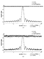
図4(a)は、従来のスライディング相関処理を用いた場合の相関値のシミュレーション結果を示し、(b)は本実施形態のフレーム同期装置30を用いた場合の相関値のシミュレーション結果を示す。横軸はサンプル数(すなわち時間)、縦軸は正規化された相関値の振幅を示す。これらのシミュレーションでは、信号対ノイズ比(SNR)を10dBとし、周波数エラーをサブキャリア間隔の0.5倍とした。
FIG. 4A shows a simulation result of the correlation value when the conventional sliding correlation process is used, and FIG. 4B shows a simulation result of the correlation value when the
図4(a)に示すように、従来のスライディング相関処理の場合、ノイズのピークレベルが0.1〜0.2であるのに対し、フレーム先頭位置を示すピークレベルは、0.6程度であり、ノイズレベルとの差異が比較的小さい。 As shown in FIG. 4A, in the case of the conventional sliding correlation processing, the peak level of the frame is about 0.6 while the peak level of the noise is 0.1 to 0.2. There is a relatively small difference from the noise level.
これに対し、図4(b)に示すように、本実施形態では、ノイズのピークレベルが0.1〜0.2に対し、フレーム先頭位置を示すピークレベルは0.9程度あり、ノイズレベルとの差異が従来と比べて大きくなっている。 On the other hand, as shown in FIG. 4B, in this embodiment, the peak level indicating the frame head position is about 0.9 while the peak level of noise is 0.1 to 0.2. The difference is larger than before.
この結果は、前述したように、従来のスライディング相関処理では1同期ワードについて1回相関処理を行っていたのに対し、本実施形態では、受信データ列r(k)と参照データ列s(k)とから複素共役積データ列z(k)を生成し(第1の相関処理)、得られた複素共役積データ列z(k)の先頭側データ領域の各データと末尾側データ領域の各データとの相関演算(第2の相関処理)を行う構成となっていることから得られたものである。 As described above, as described above, in the conventional sliding correlation process, the correlation process is performed once for one synchronization word, whereas in the present embodiment, the received data string r (k) and the reference data string s (k ) To generate a complex conjugate product data sequence z (k) (first correlation process), and each data in the head side data region and each end data region of the obtained complex conjugate product data sequence z (k) This is obtained from the configuration for performing the correlation calculation with the data (second correlation processing).
図5(a)は、周波数オフセットに対する相関値のシミュレーション結果(ノイズ無し)を示し、図5(b)は、周波数オフセットに対する相関値のシミュレーション結果(ノイズ有り)を示す。横軸は周波数オフセット(周波数エラー)、縦軸は正規化された相関値の振幅を示す。図中、黒丸と白丸でプロットされた部分は、本実施形態のフレーム同期装置30によるシミュレーション結果であり、そのうち、黒丸はパラメータMが8の場合、白丸はパラメータMが96の場合を示す。また、図中、三角でプロットされた部分は、従来のスライディング相関処理によるシミュレーション結果を示す。
FIG. 5A shows a simulation result (no noise) of the correlation value with respect to the frequency offset, and FIG. 5B shows a simulation result (with noise) of the correlation value with respect to the frequency offset. The horizontal axis indicates the frequency offset (frequency error), and the vertical axis indicates the amplitude of the normalized correlation value. In the drawing, the black and white circles plot the simulation results by the
図5(b)は、加法性白色ガウスノイズの存在下におけるシミュレーションの結果を示している。これらのシミュレーションでは、信号対ノイズ比(SNR)を10dBとし、サンプル数(データ数)Nを128とした。 FIG. 5B shows the result of simulation in the presence of additive white Gaussian noise. In these simulations, the signal-to-noise ratio (SNR) was 10 dB, and the number of samples (number of data) N was 128.
図5(a)に示すように、従来のスライディング相関処理においては、周波数オフセット(周波数エラー)がサブキャリア間隔の±1倍程度の大きさのところで、相関値の振幅が急激に減少している。これに対し、本実施形態では、周波数オフセット(周波数エラー)の大きさに関わらず、相関値の振幅はほぼ1で一定している。すなわち、本実施形態では、周波数エラーが比較的大きい場合であっても、フレーム同期を正確に行うことができる。 As shown in FIG. 5 (a), in the conventional sliding correlation process, the amplitude of the correlation value decreases rapidly when the frequency offset (frequency error) is about ± 1 times the subcarrier interval. . On the other hand, in the present embodiment, the amplitude of the correlation value is substantially constant at 1 regardless of the magnitude of the frequency offset (frequency error). That is, in this embodiment, frame synchronization can be performed accurately even when the frequency error is relatively large.
また、図5(b)に示すように、本実施形態では、白色ノイズの存在下においても、相関値の振幅が0.9近くで一定している。すなわち、本実施形態では、白色ノイズにほとんど影響されることなく、フレーム同期を正確に行うことができる。 Further, as shown in FIG. 5B, in this embodiment, the amplitude of the correlation value is constant near 0.9 even in the presence of white noise. That is, in the present embodiment, frame synchronization can be performed accurately with almost no influence from white noise.
しかも、図5(a)及び図5(b)から、本実施形態のフレーム同期における周波数エラーやノイズに対する耐性は、パラメータMが変わってもほとんど変わらないことも分かる。 Moreover, it can be seen from FIGS. 5A and 5B that the tolerance to frequency errors and noise in the frame synchronization of this embodiment hardly changes even if the parameter M changes.
図6(a)は、周波数オフセット(周波数エラー)に対する周波数オフセット推定値のシミュレーション結果(ノイズ無し)を示し、図6(b)は、周波数オフセットに対する周波数オフセット推定値のシミュレーション結果(白色ノイズ有り)を示す。これらのシミュレーションでは、信号対ノイズ比(SNR)=10dBとし、サンプル数(データ数)N=128とした。横軸、縦軸とも、サブキャリア間隔=1となるように正規化している。図中、実線はパラメータM=8、破線はパラメータM=96の場合を示す。 FIG. 6A shows the simulation result (no noise) of the frequency offset estimated value with respect to the frequency offset (frequency error), and FIG. 6B shows the simulation result of the frequency offset estimated value with respect to the frequency offset (with white noise). Indicates. In these simulations, the signal-to-noise ratio (SNR) = 10 dB and the number of samples (number of data) N = 128. Both the horizontal axis and the vertical axis are normalized so that the subcarrier interval = 1. In the figure, the solid line indicates the case where the parameter M = 8, and the broken line indicates the case where the parameter M = 96.
図6(a)に示すように、推定可能な周波数エラーの範囲は、パラメータMの値に依存して変わり、M=8では、サブキャリア間隔の16倍程度である。この結果から、パラメータMの値にも依るが、従来より広い範囲で周波数エラーを推定できることが分かる。しかも、図6(b)から、推定可能な周波数エラーの範囲は、白色ノイズの存在下でもほぼ変わらないことが分かる。 As shown in FIG. 6A, the range of the frequency error that can be estimated varies depending on the value of the parameter M, and is about 16 times the subcarrier interval when M = 8. From this result, it can be seen that although it depends on the value of the parameter M, the frequency error can be estimated in a wider range than before. Moreover, it can be seen from FIG. 6B that the range of frequency errors that can be estimated does not change even in the presence of white noise.
次に、本実施形態における測定装置10の動作について図7を参照して説明する。
図7は、本実施形態におけるフレーム同期方法及び測定方法を説明するためのフローチャートである。
Next, operation | movement of the measuring
FIG. 7 is a flowchart for explaining a frame synchronization method and a measurement method in the present embodiment.
ユーザが操作部(図示省略)を操作することにより、参照データ列s(k)の各データが参照データ列記憶部41に、相関処理の対象となる先頭側及び末尾側データ領域を指定するパラメータMのデータがデータ領域設定部31に、先頭位置検出閾値が閾値記憶部33にそれぞれ記憶される(ステップS11)。
A parameter for designating each of the data in the reference data string s (k) in the reference data
ダウンコンバータ21は、DUT1から入力した入力信号aをベースバンドの信号にダウンコンバートする(ステップS12)。ADC22は、ダウンコンバートされた信号をサンプリングしてアナログ値からデジタル値に変換し(ステップS13)、直交復調部23に出力する。
The down
直交復調部23は、ADC22の出力信号をI信号成分及びQ信号成分に直交復調し、得られた直交復調信号bをフレーム同期装置30及び信号処理部50に出力する(ステップS14)。
The
基準データシフト部32は、直交復調信号bに含まれる複素データ系列のうち、基準とする基準データを設定する(ステップS15)。基準データは、直交復調信号bの複素データ系列において参照データ列に対して相関処理が行われる受信データ列の先頭データである。例えば、基準データシフト部32は、図2に示した直交復調信号b内のサンプルS0を基準データとして定める。
The reference data shift
複素共役積データ列生成部42は、基準データにより規定される受信データ列r(k)と参照データ列s(k)とから、複素共役積データ列z(k)=r(k)・s*(k)を生成する(ステップS16)。 The complex conjugate product data sequence generation unit 42 calculates a complex conjugate product data sequence z (k) = r (k) · s from the received data sequence r (k) and the reference data sequence s (k) defined by the standard data. * (K) is generated (step S16).
データ領域設定部31は、パラメータMに基づいて、複素共役積データ列z(k)の先頭側データ領域81と末尾側データ領域82を設定する(ステップS17)。ここで、先頭側データ領域81は、複素共役積データ列z(k)の先頭データから時間軸の進行方向にN−M個のサンプル数からなるデータ領域であり、末尾側データ領域82は、複素共役積のデータ列z(k)の末尾データから時間軸の進行方向とは逆方向にN−M個のサンプル数からなるデータ領域である。
Based on the parameter M, the data
相関値算出部44は、前述の[数5]に示すとおり、複素共役積データ列z(k)の先頭側データ領域81の各データと、末尾側データ領域82の各データとの間で相関演算を行って相関値Rを算出する(ステップS18)。
The correlation value calculation unit 44 correlates between each data in the head
先頭位置検出部34は、相関値Rの振幅値(絶対値)と先頭位置検出閾値とを比較する(ステップS19)。そして、先頭位置検出部34は、相関値Rの振幅値が先頭位置検出閾値を超えたか否かを判断する(ステップS20)。
The
ステップS20において、相関値Rの振幅値が先頭位置検出閾値を超えたと判断されなかった場合(ステップS20でNo)、基準データシフト部32が、基準データを1サンプル分シフトし(ステップS21)、ステップS16の処理に戻る。例えば、基準データシフト部32は、基準データを、図2に示した直交復調信号b内のサンプルS0からS1にシフトさせ、相関処理部40は、データS1を基準データとして新たな相関処理を実行する。
If it is not determined in step S20 that the amplitude value of the correlation value R exceeds the head position detection threshold (No in step S20), the reference data shift
一方、ステップS20において、相関値Rの振幅が先頭位置検出閾値を超えたと判断された場合(ステップS20でYes)、先頭位置検出部34は、検出信号cをOFDM復調部51に出力する(ステップS22)。
On the other hand, when it is determined in step S20 that the amplitude of the correlation value R exceeds the head position detection threshold (Yes in step S20), the
OFDM復調部51は、検出信号cに基づいて、直交復調部23が出力したベースバンドの信号である直交復調信号bに対し、OFDM復調処理を行って復調信号dを生成し、測定部52に出力する(ステップS23)。OFDM復調処理では、例えば、直交復調信号bに対してFFT処理を行い、得られたFFT処理信号に対してサブキャリア復調を行う。
Based on the detection signal c, the
測定部52は、OFDM復調部51が出力した復調信号dに対し、各種信号特性の測定及び解析を行う(ステップS24)。
The measuring
以上のように、本実施形態におけるフレーム同期装置30は、受信データ列r(k)と参照データ列s(k)とから複素共役積データ列z(k)を生成し(第1の相関処理)、複素共役積データ列z(k)の先頭側データ領域の各データと末尾側データ領域の各データとの相関演算(第2の相関処理)を行う構成となっている。このようにして得られた相関値の振幅は、周波数エラーの影響を受けにくく、ノイズに対する耐性も高い。したがって、本実施形態のフレーム同期装置30は、信号品質が比較的悪い場合でも、フレーム先頭位置を正確に検出することができる。
As described above, the
また、本実施形態における測定装置10は、フレーム同期装置30を備えているので、信号品質が比較的悪い場合でも、フレーム先頭位置を正確に検出して各種信号特性の測定及び解析を実施することができる。
In addition, since the measuring
(変形例)
上述の実施形態では、基準データシフト部32が基準データの位置を1サンプル(データ)ずつシフトするものとして説明したが、本発明はこれに限定されない。
(Modification)
In the above-described embodiment, the reference data shift
例えば、基準データシフト部32が、基準データの位置を、第1のデータ間隔(データピッチ)でシフトし、先頭位置検出部34が、フレームの概略の先頭位置領域を推定した後に、第1のデータ間隔よりも細かい第2のデータ間隔で概略の先頭位置領域をシフトする構成とすることもできる。
For example, after the reference data shift
具体的には、例えば、基準データシフト部32が、まず、基準データの位置を8サンプル(データ)ずつシフトし、先頭位置検出部34が、フレームの概略の先頭位置領域を推定する。次に、基準データシフト部32が、基準データの位置を1サンプル(データ)ずつシフトし、先頭位置検出部34が、フレーム先頭位置を正確に求める、という構成とする。
Specifically, for example, the reference data shift
この構成により、本実施形態における測定装置10及びフレーム同期装置30は、フレーム先頭位置の検出処理の負荷を軽減するとともに、フレーム先頭位置を正確に検出することができる。
With this configuration, the
以上説明したように、本発明は、信号品質が比較的悪い場合でも、フレーム先頭位置を正確に検出することができるという効果を有し、フレームの先頭位置を検出するフレーム同期装置及びそれを備えた測定装置並びにフレーム同期方法及び測定方法の全体に有用である。 As described above, the present invention has an effect that the head position of a frame can be accurately detected even when the signal quality is relatively poor, and includes a frame synchronization apparatus that detects the head position of a frame and the same. It is useful for the entire measurement apparatus, frame synchronization method and measurement method.
1 DUT
10 測定装置
11 表示部
20 受信部
21 ダウンコンバータ
22 ADC
23 直交復調部
30 フレーム同期装置
31 データ領域設定部(設定部)
32 基準データシフト部(シフト部)
33 閾値記憶部
34 先頭位置検出部(検出部)
40 相関処理部
41 参照データ列記憶部(記憶部)
42 複素共役積データ列生成部(生成部)
43 相関値算出部(算出部)
50 信号処理部
51 OFDM復調部
52 測定部
60 参照データ列
61 参照データ列の先頭位置
62 参照データ列の末尾位置
70 フレーム
71 フレームの先頭位置
72 フレームの末尾位置
73 同期データ列
74 同期データ列の先頭位置
75 同期データ列の末尾位置
76 受信データ列
80 複素共役積データ列
81 先頭側データ領域
82 末尾側データ領域
101 CPU
102 ROM
103 RAM
104 入出力インタフェース
a 入力信号(測定装置の入力信号)
b 直交復調信号(フレーム同期装置の入力信号)
c 検出信号
d 復調信号
1 DUT
DESCRIPTION OF
23
32 Reference data shift part (shift part)
33
40
42 Complex conjugate product data string generator (generator)
43 Correlation value calculation unit (calculation unit)
50
102 ROM
103 RAM
104 I / O interface a Input signal (input signal of measuring device)
b Quadrature demodulated signal (input signal of frame synchronizer)
c Detection signal d Demodulation signal
Claims (6)
前記既知のデータ列と同一の参照データ列(60)を記憶する記憶部(41)と、
前記入力信号のうち、基準となる基準データを定めて前記基準データを所定のデータ間隔で順次シフトするシフト部(32)と、
前記入力信号のうち前記基準データから前記参照データ列と同一サンプル数の範囲のデータ列と、前記参照データ列とにおける各先頭データから同一番目のデータ同士の複素共役積を算出して複素共役積データ列(80)を生成する生成部(42)と、
前記複素共役積データ列のうち、先頭データから一の方向に所定サンプル数の範囲の先頭側データ領域(81)、及び前記複素共役積データ列のうち、末尾データから前記一の方向とは逆方向に前記所定サンプル数の範囲の末尾側データ領域(82)を設定する設定部(31)と、
前記シフト部により前記基準データが定められるごとに、前記先頭側データ領域の各データと前記末尾側データ領域の各データとの間で相関演算を行って相関値を算出する算出部(44)と、
前記相関値に基づいて前記フレームの前記先頭位置を検出する検出部(34)と、
を備えたことを特徴とするフレーム同期装置。 A frame synchronizer (30) for detecting a head position (71) of a frame (70) including a known data string (73) in an input signal (b),
A storage unit (41) for storing the same reference data string (60) as the known data string;
A shift unit (32) for determining reference data serving as a reference among the input signals and sequentially shifting the reference data at a predetermined data interval;
A complex conjugate product is calculated by calculating a complex conjugate product of the same number of data from each head data in the reference data sequence and a data sequence in the range of the same number of samples as the reference data sequence from the reference data in the input signal A generating unit (42) for generating a data string (80);
In the complex conjugate product data sequence, the first data area (81) within a predetermined number of samples in one direction from the head data, and in the complex conjugate product data sequence, the direction opposite to the one direction from the last data. A setting unit (31) for setting a tail side data area (82) within the range of the predetermined number of samples in the direction;
A calculation unit (44) for calculating a correlation value by performing a correlation operation between each data in the head side data area and each data in the end side data area each time the reference data is determined by the shift unit; ,
A detection unit (34) for detecting the head position of the frame based on the correlation value;
A frame synchronization apparatus comprising:
前記検出部は、前記第1のデータ間隔に基づいて前記フレームの前記先頭位置が含まれる先頭位置領域を推定し、推定した前記先頭位置領域において前記第2のデータ間隔に基づいて前記フレームの前記先頭位置を検出する、
ことを特徴とする請求項1に記載のフレーム同期装置。 The shift unit sequentially shifts the reference data at a first data interval, and then shifts the reference data at a second data interval that is narrower than the first data interval.
The detection unit estimates a head position region including the head position of the frame based on the first data interval, and the estimated position of the frame based on the second data interval in the head position region estimated. Detect start position,
The frame synchronizer according to claim 1.
前記入力信号をベースバンド信号にダウンコンバートするダウンコンバータ(21)と、
ダウンコンバートされた前記ベースバンド信号に含まれる前記フレームの先頭位置(71)を前記フレーム同期装置が検出した信号である検出信号(c)に基づいて、前記ベースバンド信号を復調して復調信号(d)を出力する復調信号出力部(51)と、
出力された前記復調信号の信号特性を測定する測定部(12)と、
を備えたことを特徴とする測定装置。 A measuring device (10) comprising the frame synchronizer (30) according to claim 1 or 2, and measuring a signal characteristic of an input signal (a) including a frame (70) including a known data string. And
A down converter (21) for down-converting the input signal into a baseband signal;
The baseband signal is demodulated by demodulating the baseband signal based on the detection signal (c), which is a signal detected by the frame synchronizer, of the start position (71) of the frame included in the downconverted baseband signal. a demodulated signal output unit (51) for outputting d);
A measurement unit (12) for measuring the signal characteristics of the output demodulated signal;
A measuring apparatus comprising:
前記既知のデータ列と同一の参照データ列(60)を記憶する記憶ステップ(S11)と、
前記入力信号のうち、基準となる基準データを定めて前記基準データを所定のデータ間隔で順次シフトするシフトステップ(S15)と、
前記入力信号のうち前記基準データから前記参照データ列と同一サンプル数の範囲のデータ列と、前記参照データ列とにおける各先頭データから同一番目のデータ同士の複素共役積を算出して複素共役積データ列(80)を生成する生成ステップ(S16)と、
前記複素共役積データ列のうち、先頭データから一の方向に所定サンプル数の範囲の先頭側データ領域(81)、及び前記複素共役積データ列のうち、末尾データから前記一の方向とは逆方向に前記所定サンプル数の範囲の末尾側データ領域(82)を設定する設定ステップ(S17)と、
前記シフトステップにより前記基準データが定められるごとに、前記先頭側データ領域の各データと前記末尾側データ領域の各データとの間で相関演算を行って相関値を算出する算出ステップ(S18)と、
前記相関値に基づいて前記フレームの前記先頭位置を検出する検出ステップ(S22)と、
を備えたことを特徴とするフレーム同期方法。 A frame synchronization method for detecting a head position (71) of a frame (70) including a known data string (73) in an input signal (b),
A storage step (S11) for storing the same reference data string (60) as the known data string;
A shift step (S15) of determining reference data serving as a reference among the input signals and sequentially shifting the reference data at a predetermined data interval;
A complex conjugate product is calculated by calculating a complex conjugate product of the same number of data from each head data in the reference data sequence and a data sequence in the range of the same number of samples as the reference data sequence from the reference data in the input signal A generation step (S16) for generating a data string (80);
In the complex conjugate product data sequence, the first data area (81) within a predetermined number of samples in one direction from the head data, and in the complex conjugate product data sequence, the direction opposite to the one direction from the last data. A setting step (S17) for setting a tail side data area (82) within the range of the predetermined number of samples in the direction;
A calculation step (S18) of calculating a correlation value by performing a correlation operation between each data in the head side data area and each data in the end side data area every time the reference data is determined by the shift step; ,
A detection step (S22) of detecting the head position of the frame based on the correlation value;
A frame synchronization method comprising:
前記検出ステップでは、前記第1のデータ間隔に基づいて前記フレームの前記先頭位置が含まれる先頭位置領域を推定し、推定した前記先頭位置領域において前記第2のデータ間隔に基づいて前記フレームの前記先頭位置を検出する、
ことを特徴とする請求項4に記載のフレーム同期方法。 In the shifting step, after sequentially shifting the reference data at a first data interval, the reference data is shifted at a second data interval narrower than the first data interval,
In the detection step, a head position area including the head position of the frame is estimated based on the first data interval, and the frame of the frame is estimated based on the second data interval in the estimated head position area. Detect start position,
The frame synchronization method according to claim 4, wherein:
前記入力信号をベースバンド信号にダウンコンバートするダウンコンバートステップ(S12)と、
ダウンコンバートされた前記ベースバンド信号に含まれる前記フレームの先頭位置(71)を前記フレーム同期方法で検出した信号である検出信号(c)に基づいて、前記ベースバンド信号を復調して復調信号(d)を出力する復調信号出力ステップ(S23)と、
出力された前記復調信号の信号特性を測定する測定ステップ(S24)と、
を備えたことを特徴とする測定方法。 A method for measuring a signal characteristic of an input signal (a) including a frame (70) including a known data string, comprising the frame synchronization method according to claim 4 or 5,
A down-conversion step (S12) for down-converting the input signal into a baseband signal;
Based on the detection signal (c), which is a signal obtained by detecting the head position (71) of the frame included in the down-converted baseband signal by the frame synchronization method, the baseband signal is demodulated to obtain a demodulated signal ( a demodulated signal output step (S23) for outputting d);
A measurement step (S24) for measuring the signal characteristics of the demodulated signal output;
A measurement method characterized by comprising:
Priority Applications (1)
| Application Number | Priority Date | Filing Date | Title |
|---|---|---|---|
| JP2018038755A JP6586183B2 (en) | 2018-03-05 | 2018-03-05 | Frame synchronization apparatus, measurement apparatus including the same, frame synchronization method, and measurement method |
Applications Claiming Priority (1)
| Application Number | Priority Date | Filing Date | Title |
|---|---|---|---|
| JP2018038755A JP6586183B2 (en) | 2018-03-05 | 2018-03-05 | Frame synchronization apparatus, measurement apparatus including the same, frame synchronization method, and measurement method |
Publications (2)
| Publication Number | Publication Date |
|---|---|
| JP2019153964A JP2019153964A (en) | 2019-09-12 |
| JP6586183B2 true JP6586183B2 (en) | 2019-10-02 |
Family
ID=67947277
Family Applications (1)
| Application Number | Title | Priority Date | Filing Date |
|---|---|---|---|
| JP2018038755A Active JP6586183B2 (en) | 2018-03-05 | 2018-03-05 | Frame synchronization apparatus, measurement apparatus including the same, frame synchronization method, and measurement method |
Country Status (1)
| Country | Link |
|---|---|
| JP (1) | JP6586183B2 (en) |
Families Citing this family (1)
| Publication number | Priority date | Publication date | Assignee | Title |
|---|---|---|---|---|
| WO2021039210A1 (en) | 2019-08-26 | 2021-03-04 | 日本電気株式会社 | Transport system, control device, transport method, and program |
-
2018
- 2018-03-05 JP JP2018038755A patent/JP6586183B2/en active Active
Also Published As
| Publication number | Publication date |
|---|---|
| JP2019153964A (en) | 2019-09-12 |
Similar Documents
| Publication | Publication Date | Title |
|---|---|---|
| US6628606B1 (en) | Coarse frequency offset estimator in orthogonal frequency division multiplexing receiver and method thereof | |
| EP2048509B1 (en) | Modulation signature trigger | |
| JP3214159B2 (en) | Carrier detector | |
| US20090141836A1 (en) | Reception device | |
| JP2004007692A (en) | Frequency offset estimator | |
| US7693242B2 (en) | DC offset correction for constant envelope signals | |
| KR100723528B1 (en) | Method and apparatus for estimating offset frequency | |
| JP6586183B2 (en) | Frame synchronization apparatus, measurement apparatus including the same, frame synchronization method, and measurement method | |
| JP2022021603A (en) | Receiving device and receiving method, and mobile terminal test apparatus provided with the receiving device | |
| JP4850049B2 (en) | Symbol synchronization apparatus, symbol synchronization method, and test apparatus | |
| CN110492903B (en) | Method and device for acquiring spread spectrum factor of linear frequency modulation signal and readable storage medium | |
| US11362876B2 (en) | Receiving device and receiving method, and mobile terminal test apparatus provided with receiving device | |
| JP7214698B2 (en) | Receiving Device, Mobile Terminal Testing Device Equipped with Receiving Device, and Mobile Terminal Testing Method | |
| JP6431570B1 (en) | Frame synchronization apparatus, measurement apparatus including the same, frame synchronization method, and measurement method | |
| JP6657499B2 (en) | Frame synchronization apparatus, measurement apparatus including the same, frame synchronization method and measurement method | |
| JP3621055B2 (en) | How to synchronize input signals | |
| JP4253258B2 (en) | Symbol rate error measuring apparatus for OFDM modulated signal | |
| JP4323347B2 (en) | Digital modulation signal evaluation device | |
| JP6449944B1 (en) | MODULATION METHOD DETECTING DEVICE, MEASURING DEVICE INCLUDING THE SAME, MODULATION METHOD DETECTING METHOD AND MEASURING METHOD | |
| US11665042B2 (en) | Receiving device | |
| JPH09246917A (en) | Frequency error estimation device | |
| JP7026093B2 (en) | Signal analyzer and signal analysis method | |
| JP7165705B2 (en) | Receiving Device, Mobile Terminal Testing Device Equipped with Receiving Device, and Mobile Terminal Testing Method | |
| JP2010278550A (en) | Ofdm receiver | |
| JP6586151B2 (en) | Measuring apparatus and measuring method |
Legal Events
| Date | Code | Title | Description |
|---|---|---|---|
| A621 | Written request for application examination |
Free format text: JAPANESE INTERMEDIATE CODE: A621 Effective date: 20180824 |
|
| A977 | Report on retrieval |
Free format text: JAPANESE INTERMEDIATE CODE: A971007 Effective date: 20190822 |
|
| TRDD | Decision of grant or rejection written | ||
| A01 | Written decision to grant a patent or to grant a registration (utility model) |
Free format text: JAPANESE INTERMEDIATE CODE: A01 Effective date: 20190903 |
|
| A61 | First payment of annual fees (during grant procedure) |
Free format text: JAPANESE INTERMEDIATE CODE: A61 Effective date: 20190906 |
|
| R150 | Certificate of patent or registration of utility model |
Ref document number: 6586183 Country of ref document: JP Free format text: JAPANESE INTERMEDIATE CODE: R150 |
|
| R250 | Receipt of annual fees |
Free format text: JAPANESE INTERMEDIATE CODE: R250 |
|
| R250 | Receipt of annual fees |
Free format text: JAPANESE INTERMEDIATE CODE: R250 |