JP6582549B2 - Vibration detection module, vibration detection device, vibration detection method, and surgical system - Google Patents
Vibration detection module, vibration detection device, vibration detection method, and surgical system Download PDFInfo
- Publication number
- JP6582549B2 JP6582549B2 JP2015105241A JP2015105241A JP6582549B2 JP 6582549 B2 JP6582549 B2 JP 6582549B2 JP 2015105241 A JP2015105241 A JP 2015105241A JP 2015105241 A JP2015105241 A JP 2015105241A JP 6582549 B2 JP6582549 B2 JP 6582549B2
- Authority
- JP
- Japan
- Prior art keywords
- vibration
- detection module
- sensor
- medical instrument
- vibration detection
- Prior art date
- Legal status (The legal status is an assumption and is not a legal conclusion. Google has not performed a legal analysis and makes no representation as to the accuracy of the status listed.)
- Active
Links
Images


Classifications
-
- A—HUMAN NECESSITIES
- A61—MEDICAL OR VETERINARY SCIENCE; HYGIENE
- A61B—DIAGNOSIS; SURGERY; IDENTIFICATION
- A61B90/00—Instruments, implements or accessories specially adapted for surgery or diagnosis and not covered by any of the groups A61B1/00 - A61B50/00, e.g. for luxation treatment or for protecting wound edges
- A61B90/06—Measuring instruments not otherwise provided for
-
- A—HUMAN NECESSITIES
- A61—MEDICAL OR VETERINARY SCIENCE; HYGIENE
- A61B—DIAGNOSIS; SURGERY; IDENTIFICATION
- A61B17/00—Surgical instruments, devices or methods, e.g. tourniquets
- A61B17/28—Surgical forceps
- A61B17/29—Forceps for use in minimally invasive surgery
-
- A—HUMAN NECESSITIES
- A61—MEDICAL OR VETERINARY SCIENCE; HYGIENE
- A61B—DIAGNOSIS; SURGERY; IDENTIFICATION
- A61B34/00—Computer-aided surgery; Manipulators or robots specially adapted for use in surgery
- A61B34/20—Surgical navigation systems; Devices for tracking or guiding surgical instruments, e.g. for frameless stereotaxis
-
- A—HUMAN NECESSITIES
- A61—MEDICAL OR VETERINARY SCIENCE; HYGIENE
- A61B—DIAGNOSIS; SURGERY; IDENTIFICATION
- A61B34/00—Computer-aided surgery; Manipulators or robots specially adapted for use in surgery
- A61B34/25—User interfaces for surgical systems
-
- A—HUMAN NECESSITIES
- A61—MEDICAL OR VETERINARY SCIENCE; HYGIENE
- A61B—DIAGNOSIS; SURGERY; IDENTIFICATION
- A61B34/00—Computer-aided surgery; Manipulators or robots specially adapted for use in surgery
- A61B34/30—Surgical robots
- A61B34/37—Master-slave robots
-
- A—HUMAN NECESSITIES
- A61—MEDICAL OR VETERINARY SCIENCE; HYGIENE
- A61B—DIAGNOSIS; SURGERY; IDENTIFICATION
- A61B34/00—Computer-aided surgery; Manipulators or robots specially adapted for use in surgery
- A61B34/70—Manipulators specially adapted for use in surgery
- A61B34/76—Manipulators having means for providing feel, e.g. force or tactile feedback
-
- A—HUMAN NECESSITIES
- A61—MEDICAL OR VETERINARY SCIENCE; HYGIENE
- A61B—DIAGNOSIS; SURGERY; IDENTIFICATION
- A61B90/00—Instruments, implements or accessories specially adapted for surgery or diagnosis and not covered by any of the groups A61B1/00 - A61B50/00, e.g. for luxation treatment or for protecting wound edges
- A61B90/50—Supports for surgical instruments, e.g. articulated arms
-
- A—HUMAN NECESSITIES
- A61—MEDICAL OR VETERINARY SCIENCE; HYGIENE
- A61B—DIAGNOSIS; SURGERY; IDENTIFICATION
- A61B17/00—Surgical instruments, devices or methods, e.g. tourniquets
- A61B2017/00017—Electrical control of surgical instruments
- A61B2017/00022—Sensing or detecting at the treatment site
- A61B2017/00075—Motion
-
- A—HUMAN NECESSITIES
- A61—MEDICAL OR VETERINARY SCIENCE; HYGIENE
- A61B—DIAGNOSIS; SURGERY; IDENTIFICATION
- A61B17/00—Surgical instruments, devices or methods, e.g. tourniquets
- A61B2017/00017—Electrical control of surgical instruments
- A61B2017/00115—Electrical control of surgical instruments with audible or visual output
-
- A—HUMAN NECESSITIES
- A61—MEDICAL OR VETERINARY SCIENCE; HYGIENE
- A61B—DIAGNOSIS; SURGERY; IDENTIFICATION
- A61B18/00—Surgical instruments, devices or methods for transferring non-mechanical forms of energy to or from the body
- A61B2018/00053—Mechanical features of the instrument of device
- A61B2018/00297—Means for providing haptic feedback
- A61B2018/00303—Means for providing haptic feedback active, e.g. with a motor creating vibrations
-
- A—HUMAN NECESSITIES
- A61—MEDICAL OR VETERINARY SCIENCE; HYGIENE
- A61B—DIAGNOSIS; SURGERY; IDENTIFICATION
- A61B18/00—Surgical instruments, devices or methods for transferring non-mechanical forms of energy to or from the body
- A61B2018/00636—Sensing and controlling the application of energy
- A61B2018/00773—Sensed parameters
- A61B2018/0088—Vibration
-
- A—HUMAN NECESSITIES
- A61—MEDICAL OR VETERINARY SCIENCE; HYGIENE
- A61B—DIAGNOSIS; SURGERY; IDENTIFICATION
- A61B34/00—Computer-aided surgery; Manipulators or robots specially adapted for use in surgery
- A61B34/20—Surgical navigation systems; Devices for tracking or guiding surgical instruments, e.g. for frameless stereotaxis
- A61B2034/2046—Tracking techniques
- A61B2034/2048—Tracking techniques using an accelerometer or inertia sensor
-
- A—HUMAN NECESSITIES
- A61—MEDICAL OR VETERINARY SCIENCE; HYGIENE
- A61B—DIAGNOSIS; SURGERY; IDENTIFICATION
- A61B34/00—Computer-aided surgery; Manipulators or robots specially adapted for use in surgery
- A61B34/20—Surgical navigation systems; Devices for tracking or guiding surgical instruments, e.g. for frameless stereotaxis
- A61B2034/2046—Tracking techniques
- A61B2034/2063—Acoustic tracking systems, e.g. using ultrasound
-
- A—HUMAN NECESSITIES
- A61—MEDICAL OR VETERINARY SCIENCE; HYGIENE
- A61B—DIAGNOSIS; SURGERY; IDENTIFICATION
- A61B90/00—Instruments, implements or accessories specially adapted for surgery or diagnosis and not covered by any of the groups A61B1/00 - A61B50/00, e.g. for luxation treatment or for protecting wound edges
- A61B90/06—Measuring instruments not otherwise provided for
- A61B2090/064—Measuring instruments not otherwise provided for for measuring force, pressure or mechanical tension
- A61B2090/065—Measuring instruments not otherwise provided for for measuring force, pressure or mechanical tension for measuring contact or contact pressure
Landscapes
- Health & Medical Sciences (AREA)
- Surgery (AREA)
- Life Sciences & Earth Sciences (AREA)
- Engineering & Computer Science (AREA)
- Medical Informatics (AREA)
- Veterinary Medicine (AREA)
- Biomedical Technology (AREA)
- Heart & Thoracic Surgery (AREA)
- Nuclear Medicine, Radiotherapy & Molecular Imaging (AREA)
- Molecular Biology (AREA)
- Animal Behavior & Ethology (AREA)
- General Health & Medical Sciences (AREA)
- Public Health (AREA)
- Robotics (AREA)
- Oral & Maxillofacial Surgery (AREA)
- Pathology (AREA)
- Human Computer Interaction (AREA)
- Ophthalmology & Optometry (AREA)
- Surgical Instruments (AREA)
Description
本開示は、振動検出モジュール、振動検出方法及び手術システムに関する。 The present disclosure relates to a vibration detection module, a vibration detection method, and a surgical system.
一般的に、手術時には、患者の体腔内に鉗子や内視鏡等の各種の医療用器具が挿入され、術者によって体腔外から当該医療用器具が操作される。術者の操作性を向上させるために、医療用器具の先端での患者の生体組織との接触状態を検出し、術者にフィードバックする技術が開発されている。例えば、特許文献1、2には、患者の体腔内に挿入される医療用器具の先端に、当該医療用器具と患者の生体組織との接触状態を検出するセンサ(触覚センサ又は力覚センサ)が設けられ、当該センサによって検出された接触状態が、当該医療用器具を操作する術者に対して振動として伝達される技術が開示されている。
Generally, at the time of surgery, various medical instruments such as forceps and endoscope are inserted into the body cavity of a patient, and the medical instrument is operated from outside the body cavity by an operator. In order to improve the operability of the surgeon, a technique has been developed in which the contact state of the tip of the medical instrument with the patient's living tissue is detected and fed back to the surgeon. For example, in
ここで、上述したように、特許文献1、2に記載の技術では、いずれも、接触状態を検出するためのセンサが、患者の体腔内に挿入される医療用器具の先端に設けられている。医療用器具は、当然、清潔が保たれていなければいけないため、その先端にセンサを取り付ける場合には、センサを保持しつつその清潔度を保つための特別な構造を設ける必要がある。従って、医療用器具の構造が複雑化し、コストが増大する恐れがある。また、センサが設けられる分、医療用器具の先端の構成が大型化するため、当該医療用器具を体腔内に挿入する際の患者への負担が増大したり、当該医療用器具の先端が体腔内の生体組織と誤って接触する危険性が増大することが懸念される。
Here, as described above, in each of the techniques described in
そこで、本開示では、より簡易な構成によって医療用器具と生体組織との接触状態を検出することが可能な、新規かつ改良された振動検出モジュール、振動検出方法及び手術システムを提案する。 Therefore, the present disclosure proposes a new and improved vibration detection module, vibration detection method, and surgical system that can detect a contact state between a medical instrument and a living tissue with a simpler configuration.
本開示によれば、長尺の医療用器具の長手方向における一部位に着脱自在に構成され、取り付け位置と離隔した前記長手方向における他の部位において前記医療用器具に生じた振動を検出する、振動検出モジュールが提供される。 According to the present disclosure, it is configured to be detachable at a part of the longitudinal direction of the medical instrument in the longitudinal direction, and detects vibrations generated in the medical instrument at other portions in the longitudinal direction that are separated from the attachment position. A vibration detection module is provided.
また、本開示によれば、長尺の医療用器具に着脱可能に構成される振動検出モジュールを、前記医療用器具の長手方向における一部位に取り付け、前記振動検出モジュールによって、取り付け位置と離隔した前記長手方向における他の部位において前記医療用器具に生じた振動を検出する、振動検出方法が提供される。 According to the present disclosure, a vibration detection module configured to be detachable from a long medical device is attached to a part of the medical device in the longitudinal direction, and is separated from the attachment position by the vibration detection module. There is provided a vibration detection method for detecting vibration generated in the medical instrument in another part in the longitudinal direction.
また、本開示によれば、患者に対して用いられる長尺の医療用器具と、前記医療用器具を支持する支持アーム装置と、前記医療用器具の長手方向における一部位に着脱可能に構成され、取り付け位置と離隔した前記長手方向における他の部位において前記医療用器具に生じた振動を検出する振動検出モジュールと、を備える、手術システムが提供される。 Further, according to the present disclosure, a long medical instrument used for a patient, a support arm device that supports the medical instrument, and a part of the medical instrument that is detachable in a longitudinal direction are configured. And a vibration detection module that detects vibration generated in the medical instrument at another portion in the longitudinal direction separated from the attachment position.
本開示によれば、医療用器具に着脱可能な振動検出モジュールが提供される。また、長尺の医療用器具の長手方向における一部位に当該振動検出モジュールを取り付け、当該振動検出モジュールによって、その取り付け位置と離隔した前記長手方向における他の部位において前記医療用器具に生じた振動を検出することが可能になる。従って、滅菌処理を行う際には、振動検出モジュールを取り外して、医療用器具及び振動検出モジュールのそれぞれに対して別個に滅菌処理を行えばよいため、滅菌処理を考慮した特別な構成を医療用器具に設ける必要がない。また、医療用器具の実際に患者の生体組織と近接又は接触し得る先端には振動検出モジュールが取り付けられないため、医療用器具の先端に清潔を保つための特別な構成を設ける必要がない。よって、医療用器具の構成をより簡易なものとすることができる。 According to the present disclosure, a vibration detection module that can be attached to and detached from a medical instrument is provided. Further, the vibration detection module is attached to a part of the long medical instrument in the longitudinal direction, and the vibration generated by the vibration detection module in the other part in the longitudinal direction separated from the attachment position. Can be detected. Therefore, when performing the sterilization process, the vibration detection module may be removed and the medical instrument and the vibration detection module may be separately sterilized. There is no need to install in the instrument. In addition, since the vibration detection module is not attached to the tip of the medical instrument that can actually approach or come into contact with the living tissue of the patient, it is not necessary to provide a special configuration for keeping the medical instrument clean. Therefore, the configuration of the medical instrument can be simplified.
以上説明したように本開示によれば、より簡易な構成によって医療用器具と生体組織との接触状態を検出することが可能になる。なお、上記の効果は必ずしも限定的なものではなく、上記の効果とともに、又は上記の効果に代えて、本明細書に示されたいずれかの効果、又は本明細書から把握され得る他の効果が奏されてもよい。 As described above, according to the present disclosure, it is possible to detect a contact state between a medical instrument and a living tissue with a simpler configuration. Note that the above effects are not necessarily limited, and any of the effects shown in the present specification, or other effects that can be grasped from the present specification, together with the above effects or instead of the above effects. May be played.
以下に添付図面を参照しながら、本開示の好適な実施の形態について詳細に説明する。なお、本明細書及び図面において、実質的に同一の機能構成を有する構成要素については、同一の符号を付することにより重複説明を省略する。 Hereinafter, preferred embodiments of the present disclosure will be described in detail with reference to the accompanying drawings. In addition, in this specification and drawing, about the component which has the substantially same function structure, duplication description is abbreviate | omitted by attaching | subjecting the same code | symbol.
なお、説明は以下の順序で行うものとする。
1.振動検出モジュールの構成
2.手術システムの構成
3.支持アーム装置の構成例
4.変形例
4−1.振動検出モジュールの制振制御への利用
4−2.振動検出モジュールの他の適用例
4−3.他の振動センサの検出値の利用
4−4.指向性振動センサの利用
4−5.振動検出モジュールに搭載される振動センサの個数
4−6.アクチュエータの制御に関する情報の利用
4−7.振動の他の提示方法
5.補足
The description will be made in the following order.
1. 1. Configuration of vibration detection module 2. Configuration of the surgical system 3. Configuration example of support arm device Modified example 4-1. Use of vibration detection module for vibration suppression control 4-2. Other application examples of vibration detection module 4-3. Use of detection values of other vibration sensors 4-4. Use of directional vibration sensor 4-5. Number of vibration sensors mounted on vibration detection module 4-6. Use of information related to actuator control 4-7. 4. Other presentation methods of vibration Supplement
(1.振動検出モジュールの構成)
図1−図4を参照して、本開示の一実施形態に係る振動検出モジュールの構成について説明する。図1は、本実施形態に係る振動検出モジュールが鉗子に取り付けられた様子を示す図である。図2は、本実施形態に係る振動検出モジュールの外観を示す斜視図である。図3は、本実施形態に係る振動検出モジュールの分解斜視図である。図4は、本実施形態に係る振動検出モジュールを鉗子の挿通方向に沿って切断した際の断面の様子を示す斜視図である。なお、図4では、本実施形態に係る振動検出モジュールと鉗子との位置関係を示すために、当該鉗子も併せて図示している。
(1. Configuration of vibration detection module)
With reference to FIGS. 1-4, the structure of the vibration detection module which concerns on one Embodiment of this indication is demonstrated. FIG. 1 is a diagram illustrating a state in which the vibration detection module according to the present embodiment is attached to forceps. FIG. 2 is a perspective view showing an appearance of the vibration detection module according to the present embodiment. FIG. 3 is an exploded perspective view of the vibration detection module according to the present embodiment. FIG. 4 is a perspective view showing a state of a cross section when the vibration detection module according to the present embodiment is cut along the insertion direction of the forceps. In FIG. 4, in order to show the positional relationship between the vibration detection module according to the present embodiment and the forceps, the forceps are also illustrated.
図1を参照すると、手術時に患者に対して用いられる医療用器具の一例である鉗子301に対して、本実施形態に係る振動検出モジュール10が取り付けられた様子が図示されている。このように、本実施形態に係る振動検出モジュール10は、医療用器具に取り付けられて用いられ、当該医療用器具に生じる振動を検出するものである。
Referring to FIG. 1, a state in which the
図1に示すように、鉗子301は、各種の医療用器具を支持可能に構成される支持アーム装置のアーム部303によって支持されており、当該アーム部303によって鉗子301の位置及び姿勢が制御される。
As shown in FIG. 1, the
本実施形態では、アーム部303は、いわゆるマスター/スレイブ方式によって動作される。すなわち、アーム部303は、アーム部303及び鉗子301から離隔して設置されるコントローラ等の入力装置を介して、術者によって遠隔操作され得る。
In the present embodiment, the
鉗子301は、その先端にエンドエフェクタが設けられた、長尺な管状の器具である。手術時には、当該先端を含む所定の長さの領域が、患者の体腔内に挿入される。エンドエフェクタは開閉可能な一対のブレードからなり、当該ブレードによって、患者の生体組織の把持や切断、又は生体組織の縫合時における針の把持等を行うことができる。
The
本実施形態では、鉗子301は、マスター/スレイブ方式によって動作される、いわゆるロボット鉗子である。例えば、鉗子301は、上述したアーム部303を遠隔操作するための入力装置を介して、術者によって、アーム部303とともに遠隔操作され得る。簡単のため図示は省略しているが、鉗子301には、エンドエフェクタの位置及び姿勢を変化させるための1つ又は複数の関節部が設けられていてもよく、術者は、入力装置を介した操作により、各関節部を動作させてエンドエフェクタの位置及び姿勢を調整したり、エンドエフェクタに開閉動作を行わせたりすることができる。
In the present embodiment, the
このように、本実施形態では、いわゆるマスター/スレイブ方式の手術システムに対して振動検出モジュール10が適用される。マスター/スレイブ方式の手術システムでは、複数のアーム部によって、各種の医療用器具や術部を観察するための観察ユニット(例えば、顕微鏡や内視鏡等)がそれぞれ支持され、これら複数のアーム部及び医療用器具が、当該複数のアーム部から離隔して設置されるコントローラ等の入力装置を介して術者によって遠隔操作されることにより、手術が行われる。本実施形態に係る振動検出モジュール10は、これらの各種の医療用器具の1つ又は複数に取り付けられ得る。なお、マスター/スレイブ方式の手術システムについては、下記(2.手術システムの構成)で改めて説明する。
Thus, in the present embodiment, the
なお、本実施形態において想定される手術は、開腹手術及び内視鏡手術の両方であり得る。例えば、開腹手術であれば、術部を電子的に撮影することが可能ないわゆるビデオ式顕微鏡によって術部が撮影される。また、内視鏡手術であれば、鉗子301とともに内視鏡が患者の体腔内に挿入され、当該内視鏡によって術部が撮影される。ビデオ式顕微鏡や内視鏡等の観察ユニットによって撮影された術部の画像は、術者によって視認され得る位置に配置される表示装置に表示され、術者は、当該表示装置に映し出された画像によって術部の様子を観察しながら手術を行う。なお、当該表示装置は、手術室内に設置されてもよいし、ヘッドマウントディスプレイ(HMD:Head Mounted Display)や眼鏡型のウェアラブルデバイスのように、術者が身に付けて使用するデバイスに搭載されてもよい。
In addition, the operation assumed in this embodiment may be both an abdominal operation and an endoscopic operation. For example, in the case of laparotomy, the surgical site is photographed by a so-called video microscope that can electronically photograph the surgical site. In the case of endoscopic surgery, the endoscope is inserted into the body cavity of the patient together with the
図1では、このようなマスター/スレイブ方式の手術システムの構成の中から、代表的に、1つのアーム部303、及び当該アーム部303によって支持される鉗子301のみを図示している。以下では、一例として、図1に示すように、鉗子301に対して本実施形態に係る振動検出モジュール10が取り付けられる場合を例に挙げて、振動検出モジュール10の構成及び機能について説明する。
FIG. 1 typically shows only one
振動検出モジュール10は、鉗子301の基端側(すなわち、アーム部303と接続される側)に取り付けられ、振動検出モジュール10の取り付け位置よりも先端側、すなわち患者の生体組織に近接又は接触する部位において鉗子301に生じる振動を検出する。例えば、振動検出モジュール10は、患者の体腔内に挿入された鉗子301が当該体腔内の生体組織に接触することによって当該鉗子301に生じた振動を検出することができる。このように、本実施形態によれば、体腔外に設置される振動検出モジュール10によって、体腔内における鉗子301と生体組織との接触状態が検出され得る。
The
ここで、以下の説明では、便宜的に、鉗子301において振動検出モジュール10による振動検出の対象となる部位のことを、「先端側」と呼称することとする。ただし、上述したように、振動検出モジュール10は、振動検出モジュール10の取り付け位置よりも先端側において鉗子301に生じる振動を検出するため、振動検出モジュール10は、鉗子301の先端近傍の部位だけではなく、鉗子301の中間部位(振動検出モジュール10の取り付け位置と鉗子301の先端との間の部位)において生じる振動も検出し得る。従って、当該「先端側」とは、必ずしも鉗子301の先端近傍の部位のみを指す言葉ではなく、先端及び中間部位を含む、振動検出モジュール10による振動検出の対象となる部位全体を示す言葉である。
Here, in the following description, for convenience, a part of the
なお、図1に示す例では、鉗子301に対して振動検出モジュール10が取り付けられているが、本実施形態はかかる例に限定されない。本実施形態において振動検出の対象となる器具は長尺の医療用器具であればよく、その種類は限定されない。振動検出モジュール10は、各種の長尺の医療用器具に対して取り付けられてよい。本実施形態では、振動検出モジュール10は、長尺の医療用器具の長手方向における一部位に取り付けられ、その取り付け位置と離隔した長手方向における他の部位において当該医療用器具に生じた振動を検出し得る。
In the example illustrated in FIG. 1, the
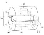
振動検出モジュール10の構成についてより詳細に説明する。図2−図4に示すように、振動検出モジュール10は、筐体110と、当該筐体110の内部に配設される第1の振動センサ120及び第2の振動センサ130と、から主に構成される。
The configuration of the
筐体110は中空の略円柱形状を有し、当該円柱形状の上面及び底面の略中央には、それぞれ開口部が設けられる。振動検出モジュール10が鉗子301に取り付けられる際には、筐体110の当該2つの開口部に鉗子301が挿通される。
The
筐体110は、当該2つの開口部を通る平面で分割される、2つの部材111、112(第1の部材111及び第2の部材112)から構成される。そして、鉗子301を挟むように第1の部材111及び第2の部材112が組み付けられることにより、筐体110(すなわち、振動検出モジュール10)が鉗子301に取り付けられる(図4を参照)。
The
このように、振動検出モジュール10は、鉗子301に対して着脱可能に構成される。この際、振動検出モジュール10は、既存の鉗子301に対して取り付け可能に構成されてよい。これにより、振動検出モジュール10を取り付けるための特別な構成を鉗子301に設ける必要がなく、既存の鉗子301をそのまま利用することができる。
Thus, the
また、振動検出モジュール10は、例えば第1の部材111及び第2の部材112に設けられる掛止部材同士を互いに掛止することにより両者が連結される等、工具を用いない簡便な方法で鉗子301に取り付け可能に構成されることが好ましい。これにより、振動検出モジュール10を鉗子301に対して取り付ける際の作業性を向上させることができる。
In addition, the
筐体110の材質は特に限定されないが、手術時に振動検出モジュール10の清潔を保つ観点から、筐体110の材料としては、抗菌性を有するもの、及び/又は滅菌処理に耐え得るものが用いられることが好ましい。また、外部の環境における雑音となり得る振動(例えば、後述する会話や音楽)が、筐体110の内部に配設される第1の振動センサ120及び第2の振動センサ130に伝達されることを抑制するために、筐体110は、比較的比重が大きい材料によって形成されることが好ましい。
Although the material of the housing | casing 110 is not specifically limited, From a viewpoint of keeping the
第1の部材111と第2の部材112との接触部(すなわち、筐体110の分割面における縁部)、及び筐体110の開口部における鉗子301との接触部(すなわち、当該開口部の縁部)には、筐体110が鉗子301に取り付けられた際に筐体110を封止するためのシーリング部材140が設けられる。シーリング部材140が設けられることにより、筐体110が鉗子301に取り付けられた際に、筐体110の内部の密閉性が保たれ、筐体110の内部に設けられる第1の振動センサ120及び第2の振動センサ130を外部の環境から遮断することができる。
A contact portion between the
例えば、手術中には、術者と他の医療スタッフとの間で会話が行われたり、術者の緊張を緩和するために音楽が流されていたりすることがある。これらの会話や音楽は、第1の振動センサ120及び第2の振動センサ130によって本来検出したい鉗子301において生じる振動に対して、雑音となり得る。シーリング部材140によって筐体110の内部の密閉性が保たれることにより、第1の振動センサ120及び第2の振動センサ130において検出され得る外部の環境に起因する雑音を低減することができる。
For example, during surgery, there may be a conversation between the surgeon and other medical staff, or music may be played to relieve the surgeon's tension. These conversations and music can become noise with respect to the vibration generated in the
例えば、シーリング部材140は、ゴム等の軟性体によって形成される。ただし、本実施形態はかかる例に限定されず、シーリング部材140としては、一般的に中空の部材の封止に用いられ得る各種の公知の部材を用いることができる。また、シーリング部材140が配設される部位は上述した部位に限定されず、例えば、第1の部材111と第2の部材112との接触部や鉗子301を挿通するための開口部以外に、筐体110の内部と外部とを空間的に接続する隙間が存在する場合には、これらの隙間を塞ぐようにシーリング部材140が適宜配設されてよい。
For example, the sealing
また、図1−図4に示す例では、シーリング部材140は、筐体110と別個の部材として構成されているが、本実施形態はかかる例に限定されない。例えば、2色成形により、筐体110を構成する第1の部材111及び第2の部材112のいずれかと、シーリング部材140とが、一体的な部材として形成されてもよい。これにより、筐体110の封止がより確実に行われることとなり、第1の振動センサ120及び第2の振動センサ130を外部の環境から遮断する効果をより得ることができる。
Moreover, in the example shown in FIGS. 1-4, the sealing
第1の振動センサ120は、ヒトの聴覚に対応する周波数帯域の振動(以下、便宜的に聴覚振動とも言う)を検出する聴覚センサである。例えば、第1の振動センサ120は、ヒトの可聴域(例えば、約20Hz〜約20kHz)に対応する周波数帯域の振動を検出する。第1の振動センサ120は、例えばマイクロフォンであり、筐体110が鉗子301に取り付けられた際に、第1の振動センサ120の収音部が鉗子301と接触するように、筐体110内に配置される。第1の振動センサ120により、鉗子301の内部を伝わってきた、鉗子301の先端側で生じた音(例えば、鉗子301のエンドエフェクタが患者の生体組織を把持した際の音等)が検出され得る。
The
図示する例では、第1の振動センサ120は、第1の部材111の内部に配置されている。図示は省略するが、第1の部材111の内部には、第1の振動センサ120を支持するための支持部材が適宜設けられており、当該支持部材によって、第1の振動センサ120が第1の部材111の内部に固定的に支持される。
In the example illustrated, the
第2の振動センサ130は、ヒトの触覚に対応する周波数帯域の振動(以下、便宜的に触覚振動とも言う)を検出する触覚センサである。例えば、第2の振動センサ130は、ヒトの皮膚での検出可能周波数帯域(例えば、数Hz〜約1kHz)に対応する周波数の振動を検出する。第2の振動センサ130は、例えば3軸以上の多軸の加速度センサである。第2の振動センサ130は、筐体110に対して固定的に配設される。第2の振動センサ130により、鉗子301を伝わってきた、鉗子301の先端側で生じた触覚振動(例えば、鉗子301のエンドエフェクタが患者の生体組織を把持した際に生じた触覚振動)が、筐体110を介して検出され得る。
The
図示する例では、第2の振動センサ130は、第2の部材112の内部に配置されている。図示は省略するが、第2の部材112の内部には、第2の振動センサ130を支持するための支持部材が適宜設けられており、当該支持部材によって、第2の振動センサ130が第2の部材112の内部に固定的に支持される。
In the illustrated example, the
第1の振動センサ120によって検出された聴覚振動を示す信号及び第2の振動センサ130によって検出された触覚振動を示す信号は、ケーブル150によって、これらの信号に対して増幅やフィルタリング等の各種の信号処理を行う回路基板等まで送信される。当該回路基板等において各種の信号処理が施された信号が、鉗子301及びアーム部303を操作する術者の手元の振動提示部(図示せず。)まで送信され、当該振動提示部によって、第1の振動センサ120によって検出された聴覚振動及び第2の振動センサ130によって検出された触覚振動が、術者に対して伝達される。
The signal indicating the auditory vibration detected by the
なお、ケーブル150は、筐体110に設けられる開口部を介して筐体110の外部まで延設され得るが、ケーブル150が挿通される当該開口部も、上述した鉗子301が挿通される開口部と同様に、シーリング部材140によって封止され得る。また、第1の振動センサ120によって検出された聴覚振動を示す信号及び第2の振動センサ130によって検出された触覚振動を示す信号は、必ずしもケーブル150によって送信されなくてもよく、各種の公知の通信方式に従って無線で上記回路基板等に送信されてもよい。
The
振動提示部は、例えば、スピーカや振動素子等によって構成される。振動提示部のスピーカによって、第1の振動センサ120によって検出された聴覚振動(すなわち音)が術者に対して伝達される。また、振動提示部の振動素子によって、第2の振動センサ130によって検出された触覚振動が術者に対して伝達される。このように鉗子301の先端側で生じた聴覚振動及び触覚振動が術者に対して伝達されることにより、術者は、鉗子301の操作中における、鉗子301と患者の生体組織との接触状態をより直感的に感じることができる。なお、このような振動提示部を介した術者への聴覚振動及び触覚振動の伝達方法については、下記(2.手術システムの構成)で改めて説明する。
The vibration presenting unit is configured by, for example, a speaker or a vibration element. The auditory vibration (that is, sound) detected by the
ここで、鉗子301が患者の生体組織に接触する際に第2の振動センサ130によって検出され得る触覚振動は、生体組織の表面テクスチャ情報、及び/又は生体組織の剛性情報を含み得る。例えば、術者は、伝達された触覚振動に基づいて、現在鉗子301が触れている生体組織の表面の状態(滑らかなのか又はざらついているのか等)や、現在鉗子301が触れている生体組織の弾性(軟らかいのか又は硬いのか等)を、感覚的に把握することができる。例えば、同一の生体組織において、病変部と正常部位とで表面の状態や剛性等が著しく異なっている場合には、このような生体組織の表面テクスチャ情報及び/又は剛性情報は、当該病変部を確認するための一助となり得る。例えば、鉗子301を生体組織の表面をなぞるように動かし、その間の触覚振動を検出し術者に対して伝達するといった、表面テクスチャ情報及び/又は剛性情報を積極的に得るような使用方法も想定され得る。
Here, the tactile vibration that can be detected by the
また、第1の振動センサ120によって検出され得る聴覚振動、すなわち生体組織が発する音は、当該生体組織が正常な状態であるかどうかを判断するために有用な情報となる場合がある。例えば、血管の縫合においては、縫合後の血管内に正常に血液が流れているかどうかを音波によって確認する検査方法が存在する。本実施形態では、このような音波を用いた各種の検査において、第1の振動センサ120によって検出された聴覚振動が用いられてもよい。
In addition, the auditory vibration that can be detected by the
このように、聴覚振動及び触覚振動が術者に対して伝達されることにより、術者は、鉗子301の先端側が接触している生体組織に関する、より多くの情報を得ることが可能になる。
In this way, the auditory vibration and the tactile vibration are transmitted to the surgeon, so that the surgeon can obtain more information regarding the living tissue with which the distal end side of the
ここで、図示は省略するが、アーム部303の鉗子301との接続部位には、力覚センサが設けられ得る。また、アーム部303を構成する各関節部には、当該各関節部に作用する力を検出するための力覚センサ(トルクセンサ)が設けられ得る。本実施形態では、鉗子301に作用する力が、これらの力覚センサによって検出され、鉗子301を操作する術者に対して伝達されてもよい。この場合、術者には、力覚センサによって検出された鉗子301に作用する力、並びに振動検出モジュール10によって検出された鉗子301の先端側で生じた聴覚振動及び触覚振動が、ともに伝達されることとなる。なお、アーム部303の鉗子301との接続部位に設けられる力覚センサは、鉗子301に作用する力を検出するために別途設けられるものであってもよいし、アーム部303の鉗子301との接続部位に関節部が配置される場合であれば、当該関節部に設けられるトルクセンサであってもよい。
Here, although illustration is omitted, a force sensor may be provided at a connection portion of the
力覚センサによる力のフィードバックによっても、術者は、鉗子301と生体組織との接触状態を把握し得る。しかしながら、一般的に、力覚センサは、例えば歪みゲージや感圧素子等からなり、力の大きさや方向が比較的高い周波数(例えば数Hz以上)で変化する場合には、その振動する力を正確に検出することは困難であることが多い。従って、力覚センサによって検出された鉗子301に作用する力を術者に対してフィードバックするだけでは、鉗子301と生体組織との接触状態を表す十分な情報が術者に対して伝達されているとは言い難いと考えられる。
The operator can grasp the contact state between the
本実施形態における第1の振動センサ120及び第2の振動センサ130は、このような力覚センサによって検出することが困難な周波数帯域の振動を検出するためのものであると言える。つまり、本実施形態によれば、第1の振動センサ120及び第2の振動センサ130によって検出された振動を術者に対してフィードバックすることにより、力覚センサによる力のフィードバックだけでは得られない、より広い周波数帯域の振動を術者に対して伝達することが可能になる。従って、術者に対して、鉗子301と生体組織との接触状態を表すより多くの情報を伝達することができるため、術者は、当該接触状態をより直感的に、より現実的なものとして感じることが可能になるのである。
It can be said that the
ここで、以下の説明では、簡単のため、第1の振動センサ120によって検出される聴覚振動及び第2の振動センサ130によって検出される触覚振動のことを、まとめて、単に「第1の振動センサ120及び第2の振動センサ130によって検出される振動」等と呼称することとする。ただし、上記の観点から、本明細書では、第1の振動センサ120及び第2の振動センサ130によって検出される「振動」(すなわち、振動検出モジュール10によって検出され得る「振動」)は、特に記載のない限り、一般的に力覚センサによって検出することが困難な周波数帯域の振動を意味するものとする。
Here, in the following description, for the sake of simplicity, the auditory vibration detected by the
以上、図1−図4を参照して、本実施形態に係る振動検出モジュール10の構成について説明した。
The configuration of the
ここで、特許文献1、2に例示される既存の構成では、鉗子等の医療用器具と患者の生体組織との接触状態を検出するためのセンサが、当該医療用器具の先端に、当該医療用器具と一体的に設けられていた。従って、医療用器具の先端の構成が大型化し、当該医療用器具を体腔内に挿入する際の患者への負担が増大したり、当該医療用器具の先端が体腔内の生体組織と誤って接触する危険性が増大する恐れがあった。
Here, in the existing configurations exemplified in
また、医療用器具に対しては手術前後に滅菌処理が行われるが、当該滅菌処理としては、オートクレーブが用いられることが一般的である。オートクレーブでは、医療用器具は高温、高圧の液体にさらされるため、特許文献1、2に記載の構成のように、センサと医療用器具とが一体的に構成される場合には、当該センサがオートクレーブの環境に耐え得るように構成されることが要求される。従って、特許文献1、2に記載の構成では、センサが配置される部位の構成を、当該センサを高温、高圧の液体から保護し得る特別なものとしたり、センサ自体をオートクレーブの環境に耐え得る特別なものとしたりする必要があり、コストが増加することが懸念される。あるいは、センサが設けられた医療用器具に対する滅菌処理ではセンサが壊れないようにオートクレーブ以外の他の方法を用いることも考えられるが、この場合には、従前とは異なる作業を医療スタッフに強いることとなるため、手術の準備や片付けを行う医療スタッフの作業が煩雑になる恐れがある。
In addition, although sterilization is performed before and after surgery for medical instruments, an autoclave is generally used as the sterilization. In an autoclave, since a medical instrument is exposed to a high-temperature and high-pressure liquid, when the sensor and the medical instrument are configured integrally as in the configurations described in
また、特許文献1、2に記載の構成では、センサが医療用器具の先端に設けられており、当該センサの検出値を示す信号に対して各種の信号処理を施す回路基板等は体腔外に設置される。従って、センサの検出値を示す信号を当該回路基板等まで送信するための配線を、当該医療用器具に沿って設ける必要がある。よって、例えば配線のための専用の構造を有するカテーテルを別途用意する等、更なるコストの増加を招く可能性がある。また、上記のように、センサの検出値を示す信号が体腔外の回路基板等まで比較的長い距離を配線によって伝送されることとなるため、その間に雑音が重畳し、信号のS/N比が悪化する恐れがある。
In the configurations described in
また、特許文献1、2に記載の構成では、センサとして、感圧素子が用いられている。一般的に、感圧素子は、その分解能に限界があり、高周波数で振動するような力や比較的小さい力は検出することが困難であるため、医療用器具と生体組織との接触状態を検出するために適しているとは言い難い。
In the configurations described in
これに対して、以上説明したように、本実施形態に係る振動検出モジュール10は、鉗子301の基端側に着脱自在に構成され、当該基端側に取り付けられた状態で鉗子301の先端側で生じる振動を検出する。従って、鉗子301の先端の構成をより簡易でより小型にすることができ、上記のような患者の負担や生体組織との意図せぬ接触の危険性を低減することができる。
On the other hand, as described above, the
また、この際、振動検出モジュール10は、既存の鉗子301に取り付け可能なように構成され得るため、鉗子301に、振動検出モジュール10を取り付けるための特別な構成を設ける必要がない。従って、鉗子301としては既存のものをそのまま用いることができ、コストの大幅な増加にはつながらない。
At this time, since the
このように、本実施形態によれば、より簡易な構成によって、医療用器具に生じる振動を検出することが可能になる。 As described above, according to the present embodiment, it is possible to detect vibration generated in the medical instrument with a simpler configuration.
また、振動検出モジュール10は、鉗子301に対して着脱自在に構成されるため、必要な時のみ振動検出モジュール10を鉗子301に取り付け、準備や片付けの段階では、振動検出モジュール10を鉗子301から取り外すことができる。よって、準備や片付けの際に鉗子301に対して行われる各処理については、従来の処理をそのまま適用することができるため、準備や片付けの際の作業が煩雑化することなく、当該作業に係る医療スタッフの利便性をより向上させることができる。
Further, since the
例えば、滅菌処理については、振動検出モジュール10を鉗子301から取り外し、振動検出モジュール10及び鉗子301に対して、それぞれ別個に滅菌処理を行うことができる。従って、鉗子301に対しては、例えばオートクレーブ等、従前と同様の方法で滅菌処理を行うことができ、医療スタッフの作業が煩雑になることがない。また、振動検出モジュール10に対しては、例えばプラズマを用いた滅菌処理等、第1の振動センサ120及び第2の振動センサ130の動作に対して影響を及ぼし難い滅菌処理の方法を用いることができる。このように、本実施形態では、振動検出モジュール10が鉗子301に対して着脱可能に構成されることにより、振動検出モジュール10及び鉗子301のそれぞれに適した方法で滅菌処理を行うことが可能になる。
For example, regarding the sterilization process, the
なお、振動検出モジュール10は、繰り返し使用されることを想定したものでなくてもよく、使い捨てを前提としたものであってもよい。この場合には、手術前における事前の滅菌処理は必要であるが、病院等の医療施設において手術後に振動検出モジュール10に対する滅菌処理を行う必要がない。従って、医療施設における振動検出モジュール10の滅菌処理に係る作業の負担を軽減することができる。あるいは、手術時に振動検出モジュール10に対してドレープが被せられてもよい。この場合には、振動検出モジュール10自体に対しては特段の滅菌処理を行う必要がないため、滅菌処理に係る作業の負担を更に軽減することができる。
Note that the
また、本実施形態では、鉗子301の基端側に取り付けられる振動検出モジュール10によって鉗子301の先端側の振動が検出されるため、振動検出モジュール10の検出値を示す信号に対して各種の信号処理を行う回路基板等を、振動検出モジュール10の比較的近くに設置することができる。従って、振動検出モジュール10と当該回路基板等とを接続する配線をより短くすることができ、配線における信号への雑音の重畳を抑制することができる。
Further, in the present embodiment, since the vibration on the distal end side of the
また、振動検出モジュール10は、聴覚振動を検出する第1の振動センサ120及び触覚振動を検出する第2の振動センサ130を備える。従って、振動検出モジュール10によれば、一般的な力覚センサでは検出することが困難な周波数帯域の振動を検出することができ、医療用器具と生体組織との接触状態をより詳細に検出することが可能になる。また、検出された聴覚振動及び触覚振動が術者に対して伝達されることにより、術者は、一般的な力覚センサによるフィードバックでは得ることのできなかった、鉗子301と患者の生体組織とのより詳細な接触状態を得ることが可能になる。なお、振動検出モジュール10は、必ずしも聴覚振動及び触覚振動の双方を検出可能に構成されなくてもよく、聴覚振動及び触覚振動の少なくともいずれかを検出可能に(すなわち、第1の振動センサ120及び第2の振動センサ130の少なくともいずれかを備えるように)構成されればよい。聴覚振動及び触覚振動の少なくともいずれかを検出可能であることにより、一般的な力覚センサでは検出することが困難な周波数帯域の振動を検出することができ、術者に、より詳細な接触状態を伝達することが可能になる。
The
例えば、聴覚振動及び触覚振動が術者に対して伝達されることにより、術者は、例えば生体組織を鉗子301で把持している感覚や、鉗子301で針を保持して生体組織に対して縫合処理を施している際の針が生体組織に刺さる感覚等を、より現実的なものとして感じることができる。従って、術者の作業性が向上する。また、例えば、鉗子301が軟組織等の脆弱組織に意図せず接触した場合に、術者は、そのことをより直感的に把握することができ、鉗子301を移動させる等、適切な対応を即座に取ることが可能になる。従って、手術時の安全性を向上させることができる。
For example, the auditory vibration and the tactile vibration are transmitted to the surgeon, so that the surgeon can hold the needle with the
(2.手術システムの構成)
図5を参照して、以上説明した本実施形態に係る振動検出モジュール10が適用され得る手術システムの構成について説明する。図5は、本実施形態に係る振動検出モジュール10が適用され得る手術システムの一構成例を示すブロック図である。
(2. Configuration of the surgical system)
With reference to FIG. 5, the structure of the surgery system to which the
図5では、本実施形態に係る手術システムとして、いわゆるマスター/スレイブ方式の手術システムの構成が図示されている。マスター/スレイブ方式の手術システムでは、マスター側で術者がコントローラ等の入力装置を介して入力した指示に応じて、スレイブ側のアーム部及び当該アーム部に取り付けられた医療用器具が駆動され、当該医療用器具によって患者の術部に対して各種の処置が施される。 FIG. 5 shows a configuration of a so-called master / slave type surgical system as the surgical system according to the present embodiment. In the master / slave type surgical system, the slave side arm unit and the medical instrument attached to the arm unit are driven in accordance with an instruction input by the operator on the master side via an input device such as a controller, Various treatments are performed on the surgical site of the patient with the medical instrument.
図5を参照すると、本実施形態に係る手術システム1は、先端に鉗子等の医療用器具が取り付けられたアーム部を有する支持アーム装置210と、当該支持アーム装置210を操作するための入力装置220と、当該入力装置220を介して入力される指示に応じて支持アーム装置210を駆動させる制御システム230と、支持アーム装置210に取り付けられる振動検出モジュール10によって検出された振動を入力装置220に伝達する振動伝達部240と、から構成される。支持アーム装置210がスレイブに対応し、入力装置220がマスターに対応する。
Referring to FIG. 5, the
なお、図5に示すブロック図では、本開示の説明のために特に必要となる構成のみを図示している。手術システム1は、図示した構成以外にも、一般的なマスター/スレイブ方式の手術システムが有する各種の構成を有してよい。図示を省略した構成については、各種の公知の構成が適用されてよいため、その詳細な説明は省略する。
In the block diagram illustrated in FIG. 5, only a configuration that is particularly necessary for the description of the present disclosure is illustrated. In addition to the illustrated configuration, the
手術システム1では、情報伝達の系統が、支持アーム装置210の駆動制御に係る系統と、振動検出モジュール10によって検出された振動の術者への伝達に係る系統と、に大きく分類され得る。まず、支持アーム装置210の駆動制御に係る系統について説明する。
In the
支持アーム装置210の駆動制御においては、入力装置220の入力部221を介して術者によって入力された支持アーム装置210のアーム部を駆動するための指示を示す情報が、制御システム230に送信される。上述したロボット鉗子のように、医療用器具が駆動部位を有する場合であれば、当該医療用器具を駆動するための指示を示す情報も、併せて、入力装置220の入力部221から制御システム230に入力され得る。
In the drive control of the
入力部221は、例えば、レバー、グリップ及び/又はボタン等の入力機構によって構成され得る。入力部221の具体的な構成はかかる例に限定されず、入力部221としては、一般的なマスター/スレイブ方式の手術システムの入力装置に設けられ得る各種の公知な構成が適用されてよい。
The
制御システム230は、支持アーム装置210の駆動制御に係る各種の演算を行う。例えば、制御システム230では、入力部221を介して入力された指示に基づいて、支持アーム装置210のアーム部を駆動するための制御量が算出される。当該アーム部は、複数のリンクが関節部によって互いに回動可能に連結されて構成され得る。例えば、支持アーム装置210の駆動制御が力制御によって行われる場合であれば、その制御量としては、術者によって指示された所望の動作をアーム部が実現するために必要な各関節部に発生させるべきトルクが算出され得る。あるいは、支持アーム装置210の駆動制御が位置制御によって行われる場合であれば、その制御量としては、術者によって指示された所望の動作をアーム部が実現するために必要な各関節部の回転角度が算出され得る。また、医療用器具が駆動部位を有する場合であれば、同様に、当該医療用器具を駆動するための制御量が制御システム230によって計算され得る。
The
本実施形態では、支持アーム装置210(アーム部及び/又は医療用器具)の駆動制御の方式としては、各種の公知の制御方式が用いられてよい。制御システム230としては、採用された制御方式に適合したものが適宜構築され得る。制御システム230の具体的な構成は、各種の制御方式に応じた既存のものと同様であってよいため、その詳細な説明は省略する。
In the present embodiment, various known control methods may be used as the drive control method of the support arm device 210 (arm unit and / or medical instrument). As the
制御システム230によって算出された制御量についての情報が、支持アーム装置210の駆動部211に送信される。駆動部211は、例えば、アーム部の各関節部に設けられる、当該各関節部を回転駆動させるためのモータに対応している。制御システム230によって算出された制御量に応じて当該モータが駆動することにより、術者が入力装置220を介して指示したようにアーム部が動作する。また、医療用器具が駆動部位を有する場合であれば、駆動部211は、当該駆動部位を動作させるためのモータに対応し得る。制御システム230によって算出された制御量に応じて当該モータが駆動することにより、術者が入力装置220を介して指示したように医療用器具が動作する。
Information about the control amount calculated by the
また、支持アーム装置210は、アーム部の状態を検出するための状態検出部212を有する。状態検出部212は、例えば、アーム部の各関節部に設けられる力覚センサ(トルクセンサ)やエンコーダに対応している。力覚センサによって、各関節部に作用する力(トルク)が検出され得る。また、エンコーダによって、各関節部の回転角度が検出され得る。状態検出部212によって検出されたアーム部の状態を示す情報は、制御システム230に送信される。制御システム230は、当該情報に基づいてアーム部の現在の状態を逐次把握しており、把握したアーム部の現在の状態に基づいて上述した制御量を算出する。
In addition, the
ここで、力覚センサによって検出される各関節部に作用する力は、アーム部の先端に取り付けられる医療用器具に作用する力を反映したものであり得る。手術システム1では、制御システム230によって、力覚センサによって検出された各関節部に作用する力の中から医療用器具に作用する力の成分が抽出され、入力装置220の力提示部222に送信される。力提示部222は、例えばサーボモータ等によって構成され、医療用器具に作用する力に応じて、例えば術者による入力部221の操作に対して抵抗を与えるように入力部221を構成するレバー等を駆動させることにより、医療用器具に作用する力を術者に対して提示する。このように、手術システム1は、医療用器具に作用した力を検出し、当該力を術者に対してフィードバックする機能を備えている。
Here, the force acting on each joint detected by the force sensor may reflect the force acting on the medical instrument attached to the tip of the arm. In the
次に、振動検出モジュール10によって検出された振動の伝達に係る系統について説明する。手術システム1では、支持アーム装置210において、振動検出モジュール10が医療用器具の基端側に取り付けられる。上記(1.振動検出モジュールの構成)で説明したように、振動検出モジュール10には第1の振動センサ120及び第2の振動センサ130が搭載されており、これらの振動センサによって、医療用器具に生じた聴覚振動及び触覚振動が検出される。
Next, a system related to transmission of vibration detected by the
第1の振動センサ120は、例えばコンデンサマイクであり、鉗子に生じた聴覚振動(すなわち、音)を検出する。第2の振動センサ130は、例えば加速度センサであり、鉗子に生じた触覚振動を検出する。第1の振動センサ120及び第2の振動センサ130によって検出された振動を示す信号は、振動伝達部240を介して、入力装置220の振動提示部223に送信される。
The
具体的には、振動伝達部240は、振動検出モジュール10によって検出された振動を示す信号に対して、増幅処理やフィルタリング処理等の各種の信号処理を行い、処理後の信号を振動提示部223に対して送信する。例えば、振動伝達部240は、信号を適宜増幅するアンプや、検出された振動から有意な周波数帯域の成分のみを抽出するフィルタ等から構成される。
Specifically, the
また、入力装置220の振動提示部223は、振動検出モジュール10によって検出された振動を術者に対して提示するための各種のデバイスによって構成される。本実施形態では、振動提示部223は、例えばスピーカやイヤホン等の音声出力機器からなる聴覚振動提示部224と、例えばボイスコイル等の振動素子からなる触覚振動提示部225と、を含む。
The
図示する例では、振動伝達部240は、プリAMP241、244、ローパスフィルタ242、245(LPF242、245)及びメインAMP243、246を有する。第1の振動センサ120によって検出された聴覚振動を示す信号は、プリAMP241によって増幅され、LPF242によって低周波数帯域の周波数成分のみが抽出され、メインAMP243によって当該低周波数帯域の周波数成分が増幅されて、入力装置220の聴覚振動提示部224に送信される。聴覚振動提示部224のスピーカ等から、プリAMP241、LPF242及びメインAMP243によって処理された後の聴覚振動を示す信号に対応する音声が出力されることにより、医療用器具に生じた聴覚振動が術者に対して伝達される。
In the illustrated example, the
また、第2の振動センサ130によって検出された触覚振動を示す信号は、プリAMP244によって増幅され、LPF245によって低周波数帯域の周波数成分のみが抽出され、メインAMP246によって当該低周波数帯域の周波数成分が増幅されて、入力装置220の触覚振動提示部225に送信される。触覚振動提示部225のボイスコイル等が、プリAMP244、LPF245及びメインAMP246によって処理された後の触覚振動を示す信号に応じて振動することにより、医療用器具に生じた触覚振動が術者に対して伝達される。
Further, the signal indicating the tactile vibration detected by the
LPF242、245によって有意な周波数成分のみが抽出されることにより、雑音が低減され、検出された振動のうち術者にとってより有用と考えられる成分のみが当該術者に対して伝達され得る。また、メインAMP243、246によって、LPF242、245によって抽出された周波数成分が増幅されることにより、術者にとってより有用と考えられる成分が強調されて当該術者に対して伝達され得る。このように、振動伝達部240によって適宜信号処理が行われることにより、雑音が低減されたより明りょうな振動が術者に対して提示されることとなる。
By extracting only significant frequency components by the
なお、プリAMP241、244は、振動伝達部240の一機能として振動検出モジュール10と別個の部材として設けられなくてもよく、振動検出モジュール10内に設けられてもよい。これにより、振動検出モジュール10によって検出された振動を示す信号を振動伝達部240まで伝達する間に当該信号に重畳し得る雑音を、より低減することが可能になる。
Note that the
また、振動伝達部240の構成は図示した例に限定されない。振動伝達部240は、振動検出モジュール10に設けられる振動センサの特性に応じて、当該振動センサによって検出された振動から所望の周波数成分がより強調され得るように、適宜構成されてよい。例えば、医療用器具が近接又は接近している生体組織の異常を示す周波数帯域のような、術者に対してより強調して伝達されるべき周波数帯域が予め判明している場合であれば、当該周波数帯域の成分をより強調し得るように、振動伝達部240が構成されてよい。また、振動伝達部240においては、上述した増幅処理やフィルタリング処理以外にも、振動を示す信号に対する信号処理として一般的に行われている各種の処理が実行されてよい。振動伝達部240の構成としては、これらの機能が実現され得るような、各種の公知な構成が適用されてよい。
Further, the configuration of the
また、振動提示部223の構成も、以上説明した構成に限定されない。振動提示部223は、聴覚振動及び触覚振動が適切に術者に対して伝達され得るように、適宜構成されてよい。振動提示部223の構成としては、振動をヒトに対して提示する際に用いられる各種の公知な構成が適用されてよい。なお、振動提示部223の他の構成例については、下記(4−7.振動の他の提示方法)でも改めて説明する。
Further, the configuration of the
以上、図5を参照して、本実施形態に係る振動検出モジュール10が適用され得る手術システム1の構成について説明した。
The configuration of the
(3.支持アーム装置の構成例)
図6を参照して、図5に示す手術システム1のスレイブを構成し得る支持アーム装置の一構成例を説明する。図6は、本実施形態に係る手術システム1のスレイブを構成し得る支持アーム装置の一構成例を示す図である。
(3. Configuration example of support arm device)
With reference to FIG. 6, one structural example of the support arm apparatus which can comprise the slave of the
図6を参照すると、支持アーム装置400は、ベース部410と、アーム部420と、制御装置440と、を備える。支持アーム装置400は、上述した図5に示す支持アーム装置210に対応するものであり、手術時に鉗子等の医療用器具を支持する医療用支持アーム装置である。
Referring to FIG. 6, the
ベース部410は支持アーム装置400の基台であり、ベース部410からアーム部420が延伸される。ベース部410にはキャスターが設けられており、支持アーム装置400は、当該キャスターを介して床面と接地し、当該キャスターによって床面上を移動可能に構成されている。ただし、本実施形態に係る支持アーム装置400の構成はかかる例に限定されず、例えば、ベース部410が設けられず、手術室の天井又は壁面にアーム部420が直接取り付けられて支持アーム装置400が構成されてもよい。例えば、天井にアーム部420が取り付けられる場合には、支持アーム装置400は、アーム部420が天井から吊り下げられて構成されることとなる。
The base portion 410 is a base of the
ベース部410の内部には、図5に示す手術システム1における各種の情報処理を実行する制御装置440が設けられる。制御装置440は、例えばCPU(Central Processing Unit)やDSP(Digital Signal Processor)等のプロセッサであり得る。あるいは、制御装置440は、これらのプロセッサ及びメモリ等の記憶素子が搭載された制御基板やマイコンであり得る。制御装置440を構成するプロセッサが所定のプログラムに従って各種の信号処理を実行することにより、手術システム1における各種の動作が実行される。
Inside the base unit 410 is provided a control device 440 that executes various types of information processing in the
具体的には、制御装置440は、図5に示す制御システム230によって行われる各種の処理を実行し、支持アーム装置400の動作を統合的に制御する。また、制御装置440は、図5に示す振動伝達部240によって行われる各種の処理を実行し、振動検出モジュール10によって検出された振動を示す信号に対して、増幅やフィルタリング等の各種の処理を施した上で、当該信号を術者の手元の入力装置(図示せず。)に対して伝達する。
Specifically, the control device 440 executes various processes performed by the
アーム部420は、複数の関節部421a、421b、421c、421d、421e、421fと、関節部421a〜421eによって互いに回動可能に連結される複数のリンク422a、422b、422c、422dと、アーム部420の先端に関節部421fを介して回動可能に設けられる保持ユニット429と、を有する。また、保持ユニット429は、各種の医療用器具を保持するものであり、図示する例では、保持ユニット429には鉗子423が取り付けられている。
The
リンク422a〜422dは棒状の部材であり、リンク422aの一端が関節部421aを介してベース部410と連結され、リンク422aの他端が関節部421bを介してリンク422bの一端と連結され、更に、リンク422bの他端が関節部421c、421dを介してリンク422cの一端と連結される。更に、リンク422cの他端が、関節部421eを介して略L字状のリンク422dの一端と連結され、リンク422dの他端と鉗子423を保持する保持ユニット429とが、関節部421fを介して連結される。このように、ベース部410を支点として、複数のリンク422a〜422dの端同士が、関節部421a〜421fによって互いに連結されることにより、ベース部410から延伸されるアーム形状が構成される。
The
鉗子423は、上述した図1に示す鉗子301に対応するものである。図6では、簡単のため、鉗子423の具体的な形状の図示を省略し、簡易的に棒状の部材として図示しているが、実際には、鉗子423の先端には、患者の生体組織を把持又は切断等するためのエンドエフェクタが設けられる。手術を行う際には、鉗子423が患者の生体組織に対して所望の位置及び姿勢を取り得るように、支持アーム装置400によってアーム部420及び鉗子423の位置及び姿勢が制御される。
The
関節部421a〜421fには、アクチュエータが設けられており、関節部421a〜421fは、当該アクチュエータにより所定の回転軸に対して回転可能に構成されている。当該アクチュエータは、モータ、エンコーダ及びトルクセンサ等によって構成され得る。当該モータは、図5に示す駆動部211に対応し得るものであり、当該エンコーダ及び当該トルクセンサは、図5に示す状態検出部212に対応し得るものである。
The
各関節部421a〜421fのアクチュエータのモータの駆動が、制御装置440によってそれぞれ制御されることにより、例えばアーム部420を伸ばしたり、縮めたり(折り畳んだり)といった、アーム部420の駆動が制御される。この際、制御装置440は、アクチュエータのエンコーダ及びトルクセンサによって検出された各関節部421a〜421fの状態(すなわちアーム部420の状態)に基づいて、各アクチュエータのモータの制御量を算出し得る。
Driving of the motors of the actuators of the
なお、図示する例では、支持アーム装置400は、6つの関節部421a〜421fを有し、アーム部420の駆動に関して6自由度が実現されている。アーム部420が6自由度を有するように構成されることにより、アーム部420の可動範囲内において鉗子423を自由に移動させることができる。これにより、鉗子423を、様々な角度から患者に対して挿入することが可能になり、鉗子423を操作する際の自由度が向上する。
In the illustrated example, the
ただし、アーム部420の構成は図示する例に限定されず、関節部421a〜421f及びリンク422a〜422dの数や配置、関節部421a〜421fの駆動軸の方向等は、アーム部420が所望の自由度を有するように適宜設定されてよい。ただし、鉗子423の位置及び姿勢の自由度を考慮して、アーム部420は、好適に、6自由度以上の自由度を有するように構成され得る。
However, the configuration of the
アーム部420を動作させる際には、術者は、入力装置(図5に示す入力装置220に対応する)を介して、支持アーム装置400に対して指示を与える。入力装置を介して入力された指示を示す信号は、制御装置440に送信される。制御装置440は、各関節部421a〜421fのアクチュエータのエンコーダ及びトルクセンサによって検出された各関節部421a〜421fの状態に基づいて、当該指示に応じた各関節部421a〜421fのアクチュエータのモータの制御量を算出する。算出された当該制御量に応じて各アクチュエータのモータが駆動されることにより、術者の指示に従ってアーム部420が動作することとなる。また、鉗子423が駆動部位を有する場合であれば、同様に、入力装置を介して入力された指示に基づいて、当該駆動部位を動作させるためのモータの制御量が制御装置440によって算出され、算出された当該制御量に応じて当該モータが駆動されることにより、術者の指示に従って鉗子423が動作することとなる。なお、入力装置と制御装置440との間の通信は、有線又は無線の各種の公知の方法によって行われてよい。
When operating the
鉗子423の基端側には、振動検出モジュール10が取り付けられる。振動検出モジュール10の振動センサ(図5に示す第1の振動センサ120及び第2の振動センサ130)によって鉗子423の先端側において生じた振動が検出され、当該振動を示す信号が制御装置440に送信される。制御装置440は、当該信号に対して増幅やフィルタリング等の各種の処理(図5に示す振動伝達部240に対応する各種の処理)を施した上で、当該信号を術者の手元の入力装置に対して伝達する。入力装置に設けられる振動提示部(図5に示す振動提示部223に対応する)が当該信号に応じて駆動することにより、鉗子423の先端側で生じた振動が術者に対して伝達され得る。
The
なお、振動検出モジュール10と制御装置440との間の通信は、有線又は無線の各種の公知の方法によって行われてよい。また、振動伝達部240の機能を実行する回路基板等が、制御装置440とは分離して、振動検出モジュール10の近傍に配置されてもよい。この場合には、振動検出モジュール10と当該回路基板等とが、より短い配線によって接続され得る。これにより、振動検出モジュール10によって検出された振動を示す信号に対して、アンプによる増幅前に雑音が重畳されることがより抑制され得る。
Note that the communication between the
(4.変形例)
以上説明した実施形態に関するいくつかの変形例について説明する。
(4. Modifications)
Several modifications regarding the embodiment described above will be described.
(4−1.振動検出モジュールの制振制御への利用)
上述したように、支持アーム装置400では、アーム部420を駆動させることにより、鉗子423の位置及び姿勢が制御される。その際、支持アーム装置400では、アーム部420の移動に伴って当該アーム部420に生じる振動を抑えるために、制振制御が実行されてもよい。制振制御が行われることにより、鉗子423の位置決めを高精度に行うことが可能になり、術者の操作性を向上させることができる。
(4-1. Use of vibration detection module for vibration suppression control)
As described above, in the
制振制御のためには、通常、制振制御用の振動センサがアーム部420及び/又は鉗子423に設けられ、当該振動センサの検出値に基づいて制振制御が行われる。本実施形態では、振動検出モジュール10の検出値に基づいて制振制御が行われるように、支持アーム装置400が構成されてもよい。つまり、振動検出モジュール10が、制振制御用の振動センサの役割を兼ねてもよい。これにより、制振制御用の振動センサを新たに設けることなくアーム部420の制振制御を行うことが可能となるため、より低コストで、より簡易な構成で、制振制御を行うことが可能になる。
For vibration suppression control, a vibration sensor for vibration suppression control is usually provided in the
(4−2.振動検出モジュールの他の適用例)
上述した実施形態では、図5に示すように、本実施形態に係る振動検出モジュール10が、いわゆるマスター/スレイブ方式の手術システム1に対して適用されていた。ただし、本実施形態はかかる例に限定されず、振動検出モジュール10は他の装置又はシステムに対して適用されてもよい。
(4-2. Other Application Examples of Vibration Detection Module)
In the embodiment described above, as shown in FIG. 5, the
例えば、振動検出モジュール10は、術者が直接手で持って操作する医療用器具に対して適用されてもよい。術者が直接操作する医療用器具では、当該医療用器具の基端側に、術者が当該医療用器具を操作するためのグリッパ等の操作部が設けられており、術者は、当該操作部を直接手で操作することにより、当該医療用器具の動きを制御する。例えば、鉗子であれば、術者が基端側に設けられる操作部を操作することにより、先端のエンドエフェクタの動作が制御され得る。振動検出モジュール10は、このような術者によって直接操作される医療用器具の基端側(例えば操作部よりもやや先端側の部位)に取り付けられ、当該医療用器具の先端側で生じる振動を検出してもよい。なお、この場合には、図5に示す振動提示部223の触覚振動提示部225は、医療用器具を操作する術者の手に対して振動を伝達可能なように、当該術者によって直接保持される上記操作部に設けられ得る。
For example, the
また、例えば、振動検出モジュール10は、手術のトレーニング用の装置に設けられる医療用器具に対して適用されてもよい。この場合、当該トレーニング用の装置において振動検出モジュール10によって検出された振動の履歴が、術者と紐付けて記録されてもよい。記録された振動の履歴を解析することにより、例えば、熟練者が手術を行った場合に医療用器具に生じた振動の特性と、初心者が手術を行った場合に医療用器具に生じた振動の特性との違いを、定量的に取得することができる。また、取得された振動の特性を利用して、トレーニングを行った術者の習熟度を判断することが可能になる。この際、振動の特性に応じて、医療用器具が生体組織に対して与え得るダメージ量が定量的に示されてもよい。また、熟練者の手術時に生じた振動の特性を踏まえて練習を行うことにより、術者は、熟練者の手術の方法をより容易に習熟することができる。
For example, the
(4−3.他の振動センサの検出値の利用)
鉗子423及び/又はアーム部420に対して、振動検出モジュール10の第1の振動センサ120及び第2の振動センサ130以外の他の振動センサを取り付け、当該他の振動センサの検出値を利用することにより、振動検出モジュール10による振動の検出を、より高精度に行うことが可能になる。なお、当該他の振動センサは、振動検出モジュール10の一構成部品として振動検出モジュール10の筐体110内に設けられてもよいし、振動検出モジュール10とは別個の部材として鉗子423及び/又はアーム部420に対して取り付けられてもよい。
(4-3. Use of detection values of other vibration sensors)
A vibration sensor other than the
例えば、当該他の振動センサは、鉗子423の長手方向において第1の振動センサ120及び第2の振動センサ130よりも基端側に、既知の間隔だけ離隔して配置されてもよい。第1の振動センサ120、第2の振動センサ130及び当該他の振動センサをこのように配置することにより、これらの振動センサの検出値に基づいて、鉗子423の先端側から伝搬されてきた振動と、鉗子423の根元側から伝搬されてきた振動と、を分離して検出することが可能になる。鉗子423の根元側から伝搬されてきた振動は、例えばアーム部420の駆動に起因する振動等であり、本来検出したい振動とは異なる、雑音となり得る振動である。従って、当該構成によれば、第1の振動センサ120及び第2の振動センサ130によって検出された振動から、雑音となり得る鉗子423の根元側から伝搬されてきた振動の成分を除去することができる。よって、本来得たい振動の成分である、鉗子423の先端側から伝搬されてきた振動の成分のみを抽出することができ、鉗子423の先端側において生じた振動をより高精度に検出することが可能になる。
For example, the other vibration sensor may be arranged at a known distance apart from the
また、例えば、当該他の振動センサは、例えばアーム部420のアクチュエータのモータ等、雑音源となり得る構成の近くに配置されてもよい。当該他の振動センサによって検出された振動についての情報を用いて、振動検出モジュール10の第1の振動センサ120及び第2の振動センサ130によって検出された振動に対してノイズキャンセリングを行うことにより、雑音成分をより好適に低減することができ、鉗子423の先端側において生じた振動をより高精度に検出することが可能になる。
In addition, for example, the other vibration sensor may be disposed near a configuration that can be a noise source, such as a motor of an actuator of the
なお、上述したような第1の振動センサ120及び第2の振動センサ130によって検出された振動に対する雑音低減処理は、例えば図5に示す振動伝達部240によって実行されてよい。この場合、振動伝達部240には、図5に示す構成の他に、雑音低減処理に係る各種の信号処理を行う雑音低減部が設けられてもよい。当該雑音低減部は、CPUやDSP等のプロセッサによって構成され、当該プロセッサが所定のプログラムに従って動作することにより、雑音低減処理に係る所定の信号処理が実行され得る。なお、雑音低減処理の具体的な手法としては、各種の公知の手法が適用されてよいため、ここでは詳細な説明は省略する。
In addition, the noise reduction process with respect to the vibration detected by the
また、例えば、当該他の振動センサとして、力覚センサが設けられてもよい。つまり、振動検出モジュール10は、振動センサとして、第1の振動センサ120(すなわち聴覚センサ)及び/又は第2の振動センサ130(すなわち触覚センサ)に加えて、力覚センサを更に有するように構成されてもよい。上記(1.振動検出モジュールの構成)で説明したように、本実施形態において、第1の振動センサ120及び第2の振動センサ130は、力覚センサによって検出することが困難な周波数帯域の振動を検出するためのものであると言える。従って、力覚センサを更に有することにより、振動検出モジュール10においては、第1の振動センサ120によって検出される聴覚に対応する周波数帯域の振動、及び/又は第2の振動センサ130によって検出される触覚に対応する周波数帯域の振動に加えて、当該力覚センサによって検出される力覚に対応する周波数帯域の振動も、併せて検出することが可能になる。このように、力覚センサを更に有するように振動検出モジュール10を構成することにより、当該振動検出モジュール10によってより広い周波数帯域の振動を検出することが可能になり、振動の検出感度を向上させることができる。
For example, a force sensor may be provided as the other vibration sensor. That is, the
(4−4.指向性振動センサの利用)
第1の振動センサ120及び第2の振動センサ130として、特定の方向から伝搬された振動を抽出して検出可能な、指向性振動センサが用いられてよい。これにより、鉗子423の先端側から伝搬されてきた振動の成分のみを好適に検出することができ、鉗子423の先端側において生じた振動をより高精度に検出することが可能になる。
(4-4. Use of directional vibration sensor)
As the
(4−5.振動検出モジュールに搭載される振動センサの個数)
上述した実施形態では、振動検出モジュール10は、複数の振動センサ(聴覚振動を検出する第1の振動センサ120及び触覚振動を検出する第2の振動センサ130)を備えていた。ただし、本実施形態はかかる例に限定されず、聴覚振動及び触覚振動を検出可能であれば、振動検出モジュール10に搭載される振動センサは1つであってもよい。例えば、振動検出モジュール10は、触覚に対応する周波数帯域の振動だけでなく聴覚に対応する周波数帯域の振動まで検出可能な、より広い検出範囲を有する多軸加速度センサを1つだけ、振動センサとして備えるように構成されてもよい。この場合には、当該1つの多軸加速度センサが聴覚センサ及び触覚センサを兼ねることができる。
(4-5. Number of vibration sensors mounted on the vibration detection module)
In the above-described embodiment, the
(4−6.アクチュエータの制御に関する情報の利用)
上記(4−3.他の振動センサの検出値の利用)で説明したように、アーム部420に設けられるアクチュエータのモータは、振動検出モジュール10による振動の検出において雑音源となり得る。アクチュエータの制御に関する情報を用いて、振動検出モジュール10によって検出された振動を補正することにより、当該アクチュエータのモータの駆動に起因する雑音成分を除去することができ、鉗子423の先端側で生じた振動をより高精度に検出することが可能になる。
(4-6. Use of information related to actuator control)
As described above (4-3. Use of Detection Values of Other Vibration Sensors), the motor of the actuator provided in the
具体的には、例えば、アーム部420に設けられるアクチュエータのモータの回転数と、その際に生じる振動の特性(例えば周波数等)との関係を予め取得しておく。そして、振動検出モジュール10によって振動が検出された際のモータの回転数についての情報に基づいて、その際のモータの駆動に起因して生じる振動の特性についての情報を取得し、当該振動の特性についての情報を用いて、振動検出モジュール10によって検出された振動に対してノイズキャンセリングを行う。これにより、振動検出モジュール10によって検出された振動からアクチュエータのモータの駆動に起因する雑音成分を除去することができる。
Specifically, for example, the relationship between the rotational speed of the motor of the actuator provided in the
アクチュエータのモータの回転数についての情報は、当該アクチュエータの駆動を制御する制御システムから得ることができる。例えば、図5に示す手術システム1であれば、制御システム230から、振動伝達部240に対して、アクチュエータのモータの回転数についての情報が提供されてよい。振動伝達部240は、当該モータの回転数についての情報に基づいて、上述したようなノイズキャンセリング処理を施した上で、振動を示す信号を入力装置220に伝達することができる。この場合、上記(4−3.他の振動センサの検出値の利用)と同様に、振動伝達部240には、図5に示す構成の他に、雑音低減処理に係る信号処理を行う雑音低減部が設けられてもよく、モータの回転数についての情報に基づくノイズキャンセリング処理は、当該雑音低減部によって実行されてよい。
Information about the rotation speed of the motor of the actuator can be obtained from a control system that controls the driving of the actuator. For example, in the case of the
(4−7.振動の他の提示方法)
上述した実施形態では、振動提示部は、第1の振動センサ120によって検出された聴覚振動を術者に対して伝達するスピーカ等の音声出力機器と、第2の振動センサ130によって検出された触覚振動を術者に対して伝達するボイスコイル等の振動素子と、によって構成されていた。しかしながら、聴覚振動及び触覚振動の術者への提示方法はかかる例に限定されない。聴覚振動及び触覚振動は、一般的に振動の伝達方法として想定され得る各種の方法によって、術者に対して提示されてよい。
(4-7. Other presentation methods of vibration)
In the above-described embodiment, the vibration presenting unit is a sound output device such as a speaker that transmits the auditory vibration detected by the
例えば、振動提示部は、検出された聴覚振動及び触覚振動に関する情報(例えば、周波数等の特性を示す情報)を、文字、グラフ(波形)及び/又は色等によって、術者に対して視覚的に通知する、表示装置を含んでもよい。当該表示装置は、手術室内に設置されるものであってもよいし、HMDや眼鏡型のウェアラブルデバイスのように術者が身に付けて使用するデバイスに搭載されるものであってもよい。これらの表示装置は、例えば、通常は、内視鏡やビデオ式顕微鏡等の観察ユニットによって術部の様子を観察しながら手術を行う場合に、当該観察ユニットによって撮影された術部の画像を表示するために用いられるものであり得る。つまり、内視鏡等の観察ユニットによって撮影された術部の映像を表示する表示装置に、当該映像とともに、聴覚振動及び触覚振動に関する情報が表示されてよい。 For example, the vibration presenting unit visually displays information related to the detected auditory vibration and tactile vibration (for example, information indicating characteristics such as frequency) to the operator using characters, graphs (waveforms), and / or colors. A display device may be included. The display device may be installed in an operating room, or may be mounted on a device worn by an operator such as an HMD or glasses-type wearable device. These display devices, for example, usually display an image of the surgical part taken by the observation unit when performing surgery while observing the state of the surgical part with an observation unit such as an endoscope or a video microscope. It can be used to do. That is, information related to auditory vibration and tactile vibration may be displayed together with the video on a display device that displays the video of the surgical site taken by an observation unit such as an endoscope.
ここで、上記(1.振動検出モジュールの構成)で説明したように、触覚振動は、鉗子423が接触している生体組織の表面テクスチャ情報や剛性情報を含み得る。振動提示部として振動素子が用いられる場合には、術者は、これらの情報を、当該振動素子によって触覚を通じて感覚的に把握することができるが、より明示的に視覚及び/又は聴覚を通じてこれらの情報が通知された方が有用である場合もある。例えば、触覚振動の特性に基づいて、現在鉗子423が接触している生体組織の表面の状態や剛性(弾性)が正常なものとは異なると判断され得る場合には、その旨の情報が、術者に対して文字及び/又は音声等によって視覚的及び/又は聴覚的に通知されてもよい。例えば切除対象である病変部と正常な部位とで表面の状態や剛性が異なる場合には、当該情報が術者に対して視覚的及び/又は聴覚的に通知されることにより、術者は、現在鉗子423が病変部に接触している可能性があることをより明確に把握することが可能となる。
Here, as described in the above (1. Configuration of vibration detection module), the tactile vibration can include surface texture information and stiffness information of the living tissue with which the
(5.補足)
以上、添付図面を参照しながら本開示の好適な実施形態について詳細に説明したが、本開示の技術的範囲はかかる例に限定されない。本開示の技術分野における通常の知識を有する者であれば、特許請求の範囲に記載された技術的思想の範疇内において、各種の変更例または修正例に想到し得ることは明らかであり、これらについても、当然に本開示の技術的範囲に属するものと了解される。
(5. Supplement)
The preferred embodiments of the present disclosure have been described in detail above with reference to the accompanying drawings, but the technical scope of the present disclosure is not limited to such examples. It is obvious that a person having ordinary knowledge in the technical field of the present disclosure can come up with various changes or modifications within the scope of the technical idea described in the claims. Of course, it is understood that it belongs to the technical scope of the present disclosure.
また、本明細書に記載された効果は、あくまで説明的又は例示的なものであって限定的ではない。つまり、本開示に係る技術は、上記の効果とともに、又は上記の効果に代えて、本明細書の記載から当業者には明らかな他の効果を奏し得る。 In addition, the effects described in the present specification are merely illustrative or illustrative, and are not limited. That is, the technology according to the present disclosure can exhibit other effects that are apparent to those skilled in the art from the description of the present specification in addition to or instead of the above effects.
なお、以下のような構成も本開示の技術的範囲に属する。
(1)長尺の医療用器具の長手方向における一部位に着脱自在に構成され、取り付け位置と離隔した前記長手方向における他の部位において前記医療用器具に生じた振動を検出する、振動検出モジュール。
(2)前記振動検出モジュールは、前記医療用器具が支持される側である基端側に取り付けられ、患者の生体組織に近接又は接触する先端側において前記医療用器具に生じる振動を検出する、前記(1)に記載の振動検出モジュール。
(3)前記振動検出モジュールは、筐体と、前記筐体内に配設される1つ又は複数の振動センサと、を備え、前記振動センサは、聴覚に対応する周波数帯域の振動及び触覚に対応する周波数帯域の振動の少なくともいずれかを検出する、前記(1)又は(2)に記載の振動検出モジュール。
(4)前記筐体の内部と外部とを空間的に接続する隙間には、前記筐体を封止するためのシーリング部材が設けられる、前記(3)に記載の振動検出モジュール。
(5)前記振動センサは、聴覚に対応する周波数帯域の振動を検出する聴覚センサと、触覚に対応する周波数帯域の振動を検出する触覚センサと、の少なくともいずれかを含む、前記(3)又は(4)に記載の振動検出モジュール。
(6)
前記振動センサは、力覚に対応する周波数帯域の振動を検出する力覚センサを更に含む、前記(5)に記載の振動検出モジュール。
(7)前記聴覚センサはマイクロフォンであり、前記触覚センサは加速度センサである、前記(5)に記載の振動検出モジュール。
(8)前記振動検出モジュールによって検出された振動が、振動提示部を介して前記医療用器具を操作する術者に対して伝達される、前記(1)〜(7)のいずれか1項に記載の振動検出モジュール。
(9)前記振動提示部は、検出された聴覚に対応する周波数帯域の振動を音声として出力する音声出力装置と、検出された触覚に対応する周波数帯域の振動に応じて振動する振動素子と、を含む、前記(8)に記載の振動検出モジュール。
(10)前記振動提示部は、検出された振動に関する情報を術者に対して視覚的に通知する表示装置、を含む、前記(8)又は(9)に記載の振動検出モジュール。
(11)前記表示装置は、検出された振動に基づいて得られる前記医療用器具が接触している患者の生体組織の表面テクスチャ情報、及び前記生体組織の剛性情報の少なくともいずれかを、術者に対して通知する、前記(10)に記載の振動検出モジュール。
(12)前記医療用器具は、支持アーム装置のアーム部によって支持され、前記アーム部及び前記医療用器具は、前記支持アーム装置から離隔して設置される入力装置を介した術者からの指示に応じて動作し、前記振動検出モジュールによって検出された振動が、前記入力装置に設けられる振動提示部を介して術者に対して伝達される、前記(1)〜(11)のいずれか1項に記載の振動検出モジュール。
(13)前記アーム部に、前記アーム部に作用する力を検出する力覚センサが設けられ、前記力覚センサによって検出された前記医療用器具に作用する力が、前記入力装置を介して術者に対して伝達される、前記(12)に記載の振動検出モジュール。
(14)前記アーム部に、前記アーム部を構成する各関節部に設けられるアクチュエータのモータが発する振動を検出するための雑音低減用振動センサが設けられ、前記雑音低減用振動センサによる検出値を用いて、前振動検出モジュールによって検出された振動から前記モータが発する振動の成分が除去されて術者に対して伝達される、前記(12)又は(13)に記載の振動検出モジュール。
(15)前記アーム部を構成する各関節部に設けられるアクチュエータのモータの回転数と、前記モータが発する振動と、の関係性を利用して、前記アーム部が動作している最中の前記モータの回転数についての情報に基づいて、前振動検出モジュールによって検出された振動から前記モータが発する振動の成分が除去されて術者に対して伝達される、前記(12)〜(14)のいずれか1項に記載の振動検出モジュール。
(16)前記振動検出モジュールによって検出された振動が、前記アーム部の制振制御に用いられる、前記(12)〜(15)のいずれか1項に記載の振動検出モジュール。
(17)前記振動検出モジュールは、筐体と、前記筐体内に前記医療用器具の長手方向に沿って所定の間隔で並設される複数の振動センサと、を備え、前記複数の振動センサによって、前記医療用器具の先端側から伝搬される振動と、前記医療用器具の基端側から伝搬される振動と、が分離して検出される、前記(1)〜(16)のいずれか1項に記載の振動検出モジュール。
(18)前記振動検出モジュールは、筐体と、前記筐体内に配設される1つ又は複数の振動センサと、を備え、前記振動センサは、所定の方向から伝搬される振動を抽出して検出可能な指向性振動センサであり、前記振動センサは、前記医療用器具の先端側から伝搬される振動を抽出して検出するように配設される、前記(1)〜(17)のいずれか1項に記載の振動検出モジュール。
(19)前記振動検出モジュールは、手術のトレーニング用の装置に設けられる前記医療用器具に取り付けられ、トレーニング時に前記医療用器具に生じる振動を検出する、前記(1)〜(18)のいずれか1項に記載の振動検出モジュール。
(20)長尺の医療用器具に着脱可能に構成される振動検出モジュールを、前記医療用器具の長手方向における一部位に取り付け、前記振動検出モジュールによって、取り付け位置と離隔した前記長手方向における他の部位において前記医療用器具に生じた振動を検出する、振動検出方法。
(21)患者に対して用いられる長尺の医療用器具と、前記医療用器具を支持する支持アーム装置と、前記医療用器具の長手方向における一部位に着脱可能に構成され、取り付け位置と離隔した前記長手方向における他の部位において前記医療用器具に生じた振動を検出する振動検出モジュールと、を備える、手術システム。
The following configurations also belong to the technical scope of the present disclosure.
(1) A vibration detection module configured to be detachable at a part of the length of a long medical instrument in the longitudinal direction, and detecting vibration generated in the medical instrument at another part in the longitudinal direction separated from the attachment position. .
(2) The vibration detection module is attached to a proximal end side that is a side on which the medical instrument is supported, and detects vibration generated in the medical instrument on a distal end side in proximity to or in contact with a living tissue of a patient. The vibration detection module according to (1).
(3) The vibration detection module includes a housing and one or a plurality of vibration sensors disposed in the housing, and the vibration sensor supports vibration and tactile sense in a frequency band corresponding to hearing. The vibration detection module according to (1) or (2), wherein at least one of vibrations in a frequency band to be detected is detected.
(4) The vibration detection module according to (3), wherein a sealing member for sealing the housing is provided in a gap that spatially connects the inside and the outside of the housing.
(5) The vibration sensor includes at least one of an auditory sensor that detects vibrations in a frequency band corresponding to hearing and a tactile sensor that detects vibrations in a frequency band corresponding to touch. The vibration detection module according to (4).
(6)
The vibration detection module according to (5), wherein the vibration sensor further includes a force sensor that detects vibration in a frequency band corresponding to the force sense.
(7) The vibration detection module according to (5), wherein the auditory sensor is a microphone, and the tactile sensor is an acceleration sensor.
(8) In any one of (1) to (7), the vibration detected by the vibration detection module is transmitted to an operator who operates the medical instrument via a vibration presentation unit. The vibration detection module described.
(9) The vibration presentation unit includes a voice output device that outputs a vibration in a frequency band corresponding to the detected auditory sense as a voice, a vibration element that vibrates according to a vibration in the frequency band corresponding to the detected tactile sense, The vibration detection module according to (8), including:
(10) The vibration detection module according to (8) or (9), wherein the vibration presentation unit includes a display device that visually notifies the surgeon of information related to the detected vibration.
(11) The display device receives at least one of the surface texture information of the biological tissue of the patient in contact with the medical instrument obtained based on the detected vibration and the stiffness information of the biological tissue. The vibration detection module according to (10), wherein the vibration detection module is notified.
(12) The medical instrument is supported by an arm part of a support arm device, and the arm part and the medical instrument are instructed from an operator via an input device installed separately from the support arm device. Any one of (1) to (11), wherein the vibration detected by the vibration detection module is transmitted to the surgeon via a vibration presenting unit provided in the input device. The vibration detection module according to item.
(13) The arm unit is provided with a force sensor for detecting a force acting on the arm unit, and the force acting on the medical instrument detected by the force sensor is operated via the input device. The vibration detection module according to (12), which is transmitted to a person.
(14) A noise reduction vibration sensor for detecting vibration generated by a motor of an actuator provided in each joint portion constituting the arm portion is provided on the arm portion, and a detection value by the noise reduction vibration sensor is obtained. The vibration detection module according to (12) or (13), wherein the vibration component generated by the motor is removed from the vibration detected by the previous vibration detection module and transmitted to the operator.
(15) Utilizing the relationship between the rotation speed of the motor of an actuator provided in each joint part constituting the arm part and the vibration generated by the motor, the arm part is in operation. Based on the information about the rotational speed of the motor, the vibration component generated by the motor is removed from the vibration detected by the previous vibration detection module and transmitted to the surgeon. The vibration detection module according to
(16) The vibration detection module according to any one of (12) to (15), wherein the vibration detected by the vibration detection module is used for vibration suppression control of the arm unit.
(17) The vibration detection module includes a housing and a plurality of vibration sensors arranged in parallel at a predetermined interval along the longitudinal direction of the medical instrument in the housing, and the plurality of vibration sensors Any one of the above (1) to (16), wherein the vibration propagated from the distal end side of the medical instrument and the vibration propagated from the proximal end side of the medical instrument are detected separately. The vibration detection module according to item.
(18) The vibration detection module includes a housing and one or more vibration sensors disposed in the housing, and the vibration sensor extracts vibration propagated from a predetermined direction. Any one of (1) to (17), wherein the vibration sensor is arranged to extract and detect vibration propagated from a distal end side of the medical instrument. The vibration detection module according to
(19) Any of (1) to (18), wherein the vibration detection module is attached to the medical instrument provided in a surgical training apparatus, and detects vibration generated in the medical instrument during training. 2. The vibration detection module according to
(20) A vibration detection module configured to be detachable from a long medical instrument is attached to a part of the medical instrument in the longitudinal direction, and the other in the longitudinal direction separated from the attachment position by the vibration detection module. The vibration detection method of detecting the vibration which arose in the said medical instrument in the site | part of this.
(21) A long medical instrument used for a patient, a support arm device that supports the medical instrument, and a part of the medical instrument that is detachable in the longitudinal direction. And a vibration detection module that detects vibration generated in the medical instrument at another site in the longitudinal direction.
1 手術システム
10 振動検出モジュール
110 筐体
120 第1の振動センサ
130 第2の振動センサ
140 シーリング部材
150 ケーブル
210、400 支持アーム装置
211 駆動部
212 状態検出部
220 入力装置
221 入力部
222 力提示部
223 振動提示部
224 聴覚振動提示部
225 触覚振動提示部
230 制御システム
240 振動伝達部
301、423 鉗子
303、420 アーム部
410 ベース部
421a〜421f 関節部
422a〜422d リンク
429 保持ユニット
440 制御装置
DESCRIPTION OF
Claims (16)
患者の生体組織に近接又は接触する先端側において前記医療用器具と前記生体組織との接触によって生じる振動及び前記生体組織側から音が前記医療用器具を伝わって生じる振動の少なくともいずれか一方の振動を検出する振動センサと、
前記振動センサが内部に配置された筐体と、を備え、
前記振動センサは、前記筐体内に前記医療用器具の長手方向に沿って所定の間隔で並設される複数のセンサを含み、
前記複数のセンサによって、前記医療用器具の前記先端側から伝搬される振動と、前記医療用器具の前記基端側から伝搬される振動と、を分離して検出する、
振動検出モジュール。 A vibration detection module in the longitudinal direction of the medical instrument of the long, the medical instrument is detachably attached to the base end side which is the side to be supported,
At least one of vibration generated by contact between the medical device and the biological tissue on the distal end side close to or in contact with the biological tissue of a patient and vibration generated when sound is transmitted from the biological tissue side through the medical device A vibration sensor for detecting
A housing in which the vibration sensor is disposed;
The vibration sensor includes a plurality of sensors arranged in parallel at a predetermined interval along the longitudinal direction of the medical instrument in the housing,
The plurality of sensors separately detect vibration propagated from the distal end side of the medical instrument and vibration propagated from the proximal end side of the medical instrument,
Vibration detection module.
前記筐体は、前記両側の各開口部を通る前記筐体の分割面によって分割された第1の部材及び第2の部材を有し、前記第1の部材及び前記第2の部材が、前記医療用器具を挟んで組み合わされ、
前記各開口部内及び前記分割面に沿う隙間には、前記筐体を封止するためのシーリング部材が設けられている、
請求項1に記載の振動検出モジュール。 The housing is provided with openings through which the medical device passes, and on both sides of the housing in the longitudinal direction of the medical device.
The housing includes a first member and a second member divided by a split surface of the housing that passes through the openings on both sides, and the first member and the second member are Combined with medical instruments,
A sealing member for sealing the housing is provided in each opening and in the gap along the dividing surface.
The vibration detection module according to claim 1.
請求項1又は2に記載の振動検出モジュール。 The vibration sensor, and auditory sensor that detects the vibration of a frequency band corresponding to the hearing, a tactile sensor for detecting vibration of a frequency band corresponding to the touch,
Vibration detecting module according to claim 1 or 2.
請求項3に記載の振動検出モジュール。 The vibration sensor further includes a force sensor that detects vibration in a frequency band corresponding to the force sense.
The vibration detection module according to claim 3 .
請求項3に記載の振動検出モジュール。 The auditory sensor is a microphone, and the tactile sensor is an acceleration sensor.
The vibration detection module according to claim 3 .
請求項1〜5のいずれか1項に記載の振動検出モジュール。 Before Symbol vibration sensor is a detectable directional vibration sensors to extract the vibration propagated from the predetermined direction, so as to detect and extract the vibration propagated from the front end side of the front Symbol medical instrument Ru arranged by Tei,
The vibration detection module of any one of Claims 1-5 .
前記振動センサによって検出された振動を示す信号が前記振動センサから送られて、前記医療用器具を操作する術者に対して前記振動を伝達する振動提示部と、を備える、
振動検出装置。 The vibration detection module according to any one of claims 1 to 6,
Said signal indicating the detected vibration by the vibration sensor is sent from the vibration sensor, and a waved portion for transmitting the vibration to the operator for operating the medical instrument,
Vibration detection device.
を含む、
請求項7に記載の振動検出装置。 The vibration presenting unit, a sound output device that outputs a vibration of a frequency band corresponding to the detected hearing as a sound, a vibration element that vibrates according to the vibration of the frequency band corresponding to the detected tactile sense,
including,
The vibration detection apparatus according to claim 7 .
請求項7又は8に記載の振動検出装置。 The vibration presenting unit includes a display device that visually notifies the surgeon of information related to the detected vibration.
Vibration detecting apparatus according to claim 7 or 8.
請求項9に記載の振動検出装置。 The display device provides the surgeon with at least one of surface texture information of a patient's living tissue that is in contact with the medical instrument obtained based on the detected vibration and stiffness information of the living tissue. Configured to notify,
The vibration detection apparatus according to claim 9 .
前記医療用器具を支持する支持アーム装置と、
請求項1〜6のいずれか1項に記載の振動検出モジュールと、
を備える、手術システム。 A long medical device used for a patient;
A support arm device for supporting the medical instrument;
The vibration detection module according to any one of claims 1 to 6 ,
A surgical system comprising:
前記支持アーム装置は、前記医療用器具を支持するアーム部を有し、
前記アーム部及び前記医療用器具は、前記入力装置を介した術者からの指示に応じて動作し、
前記入力装置は、前記振動検出モジュールによって検出された振動を、術者に対して伝達する振動提示部を有する、
請求項11に記載の手術システム。 An input device installed apart from the support arm device;
The support arm device has an arm portion that supports the medical instrument,
The arm portion and the medical instrument operates in response to an instruction from the operator through the entering-force device,
The input device includes a vibration presentation unit that transmits vibration detected by the vibration detection module to an operator.
The surgical system according to claim 11 .
前記振動提示部は、前記力覚センサによって検出された前記医療用器具に作用する力を、術者に対して伝達する、
請求項12に記載の手術システム。 The arm portion, the force sensor for detecting a force acting on the arm portion is provided,
The vibration presenting unit transmits a force acting on the medical instrument detected by the force sensor to an operator;
The surgical system according to claim 12 .
前記振動提示部は、前記雑音低減用振動センサによる検出値を用いて、前記振動検出モジュールによって検出された振動から前記モータが発する振動の成分を除去して術者に対して伝達する、
請求項12又は13に記載の手術システム。 The arm portion, noise reduction vibration sensor for detecting the motor emits vibration of the actuator provided in the respective joint portions constituting the arm portion is provided,
The waved portion, using the values detected by the vibration sensor the noise reduction is transmitted to the operator to remove the component of the vibration that the motor is emitted from the detected vibration by said vibration detection module,
The surgical system according to claim 12 or 13 .
請求項12〜14のいずれか1項に記載の手術システム。 The vibration detected by the vibration detection module is used for vibration control of the arm part.
The surgical operation system according to any one of claims 12 to 14 .
前記複数のセンサによって、前記医療用器具の前記先端側から伝搬される振動と、前記医療用器具の前記基端側から伝搬される振動と、を分離して検出する、
振動検出方法。 A vibration detection module that is detachably attached to a base end side, which is a side on which the medical instrument is supported, in a longitudinal direction of a long medical instrument, on a distal end side that is close to or in contact with a living tissue of a patient A vibration sensor for detecting at least one of vibration generated by contact between the medical instrument and the biological tissue and vibration generated when sound is transmitted from the biological tissue side through the medical instrument; and A vibration detection module comprising a plurality of sensors arranged in parallel at a predetermined interval along a longitudinal direction of the medical instrument in the housing. ,
The plurality of sensors separately detect vibration propagated from the distal end side of the medical instrument and vibration propagated from the proximal end side of the medical instrument,
Vibration detection method.
Priority Applications (5)
| Application Number | Priority Date | Filing Date | Title |
|---|---|---|---|
| JP2015105241A JP6582549B2 (en) | 2015-05-25 | 2015-05-25 | Vibration detection module, vibration detection device, vibration detection method, and surgical system |
| EP16729387.7A EP3267917A1 (en) | 2015-05-25 | 2016-05-13 | Medical apparatus, medical apparatus vibration detection method, and surgical system |
| US15/554,013 US10420625B2 (en) | 2015-05-25 | 2016-05-13 | Vibration detection module, vibration detection method, and surgical system |
| CN201680028770.4A CN107635502B (en) | 2015-05-25 | 2016-05-13 | Medical device, medical device vibration detection method, and surgical system |
| PCT/JP2016/002368 WO2016189819A1 (en) | 2015-05-25 | 2016-05-13 | Medical apparatus, medical apparatus vibration detection method, and surgical system |
Applications Claiming Priority (1)
| Application Number | Priority Date | Filing Date | Title |
|---|---|---|---|
| JP2015105241A JP6582549B2 (en) | 2015-05-25 | 2015-05-25 | Vibration detection module, vibration detection device, vibration detection method, and surgical system |
Publications (3)
| Publication Number | Publication Date |
|---|---|
| JP2016214715A JP2016214715A (en) | 2016-12-22 |
| JP2016214715A5 JP2016214715A5 (en) | 2018-06-21 |
| JP6582549B2 true JP6582549B2 (en) | 2019-10-02 |
Family
ID=56131588
Family Applications (1)
| Application Number | Title | Priority Date | Filing Date |
|---|---|---|---|
| JP2015105241A Active JP6582549B2 (en) | 2015-05-25 | 2015-05-25 | Vibration detection module, vibration detection device, vibration detection method, and surgical system |
Country Status (5)
| Country | Link |
|---|---|
| US (1) | US10420625B2 (en) |
| EP (1) | EP3267917A1 (en) |
| JP (1) | JP6582549B2 (en) |
| CN (1) | CN107635502B (en) |
| WO (1) | WO2016189819A1 (en) |
Families Citing this family (22)
| Publication number | Priority date | Publication date | Assignee | Title |
|---|---|---|---|---|
| KR20180048848A (en) | 2015-09-03 | 2018-05-10 | 스트리커 코포레이션 | A power drill having an integral depth gauge including a probe sliding across the drill bit |
| JP7244985B2 (en) | 2017-05-19 | 2023-03-23 | 川崎重工業株式会社 | Operating device and operating system |
| JP7223493B2 (en) | 2017-05-19 | 2023-02-16 | 川崎重工業株式会社 | robot system |
| US20200257270A1 (en) | 2017-10-30 | 2020-08-13 | Sony Corporation | Master-slave system and control method of the same |
| JP2019130602A (en) * | 2018-01-30 | 2019-08-08 | ソニー株式会社 | Information processing device, information processing method and program |
| JP2021182949A (en) * | 2018-08-13 | 2021-12-02 | ソニーグループ株式会社 | Medical device, medical device component and master-slave system |
| CN109040884A (en) * | 2018-08-31 | 2018-12-18 | 上海联影医疗科技有限公司 | Voice system based on Medical Devices |
| US20220034380A1 (en) * | 2019-01-18 | 2022-02-03 | Siemens Medical Solutions Usa, Inc. | Single Axis Harmonic Absorber for Cantilever Structure |
| US11517326B1 (en) | 2019-02-07 | 2022-12-06 | Stryker Corporation | Methods and systems of determining drill breakthrough during surgical drilling |
| KR102238991B1 (en) * | 2019-05-23 | 2021-04-12 | 울산대학교 산학협력단 | Apparatus and method for estimating guidewire contact status |
| CN110169826B (en) * | 2019-06-17 | 2023-06-02 | 辽宁科技大学 | Flexible vibration reduction surgical robot guide wire delivery device and method |
| EP4093314A1 (en) * | 2020-01-23 | 2022-11-30 | Promaxo, Inc. | Mri-guided robotic systems and methods for biopsy |
| DE102020108796A1 (en) | 2020-03-30 | 2021-09-30 | Carl Zeiss Meditec Ag | Medical-optical observation device with opto-acoustic sensor fusion |
| AU2022247392A1 (en) | 2021-03-31 | 2023-09-28 | Moon Surgical Sas | Co-manipulation surgical system for use with surgical instruments for performing laparoscopic surgery |
| US11832909B2 (en) | 2021-03-31 | 2023-12-05 | Moon Surgical Sas | Co-manipulation surgical system having actuatable setup joints |
| US11812938B2 (en) | 2021-03-31 | 2023-11-14 | Moon Surgical Sas | Co-manipulation surgical system having a coupling mechanism removeably attachable to surgical instruments |
| US11844583B2 (en) | 2021-03-31 | 2023-12-19 | Moon Surgical Sas | Co-manipulation surgical system having an instrument centering mode for automatic scope movements |
| US11819302B2 (en) | 2021-03-31 | 2023-11-21 | Moon Surgical Sas | Co-manipulation surgical system having user guided stage control |
| DE102021114038A1 (en) | 2021-05-31 | 2022-12-01 | Carl Zeiss Microscopy Gmbh | Microscopy system and method for monitoring microscopy operations |
| WO2023209932A1 (en) * | 2022-04-28 | 2023-11-02 | リバーフィールド株式会社 | Remote operation system |
| US11839442B1 (en) | 2023-01-09 | 2023-12-12 | Moon Surgical Sas | Co-manipulation surgical system for use with surgical instruments for performing laparoscopic surgery while estimating hold force |
| CN117452148B (en) * | 2023-12-22 | 2024-03-26 | 星玛智能电气有限公司 | Intelligent monitoring method of ring main unit |
Family Cites Families (16)
| Publication number | Priority date | Publication date | Assignee | Title |
|---|---|---|---|---|
| US4655673A (en) | 1983-05-10 | 1987-04-07 | Graham S. Hawkes | Apparatus providing tactile feedback to operators of remotely controlled manipulators |
| JPH08117228A (en) | 1994-10-25 | 1996-05-14 | Olympus Optical Co Ltd | Biological information notifying device |
| JPH1094512A (en) | 1996-09-25 | 1998-04-14 | Olympus Optical Co Ltd | Taction detector |
| US6810281B2 (en) * | 2000-12-21 | 2004-10-26 | Endovia Medical, Inc. | Medical mapping system |
| DE60111517T2 (en) | 2000-04-27 | 2006-05-11 | Medtronic, Inc., Minneapolis | VIBRATION-SENSITIVE ABLATION DEVICE |
| US8808319B2 (en) * | 2007-07-27 | 2014-08-19 | Ethicon Endo-Surgery, Inc. | Surgical instruments |
| WO2011088357A1 (en) * | 2010-01-15 | 2011-07-21 | Immersion Corporation | Systems and methods for minimally invasive surgical tools with haptic feedback |
| EP2534598A4 (en) * | 2010-02-09 | 2017-07-12 | The Trustees Of The University Of Pennsylvania | Systems and methods for providing vibration feedback in robotic systems |
| US8801710B2 (en) * | 2010-12-07 | 2014-08-12 | Immersion Corporation | Electrosurgical sealing tool having haptic feedback |
| WO2012109760A1 (en) * | 2011-02-18 | 2012-08-23 | Traumis Surgical Systems Inc. | Tool with integrated navigation and guidance system and related apparatus and methods |
| JP2013169619A (en) * | 2012-02-21 | 2013-09-02 | Seiko Epson Corp | Robot arm and robot |
| US9199098B2 (en) * | 2012-09-05 | 2015-12-01 | Olympus Corporation | Ultrasonic treatment device |
| EP3298974B1 (en) * | 2013-03-15 | 2021-08-11 | St. Jude Medical, Atrial Fibrillation Division, Inc. | Catheter with deflection measuring sensor |
| US9913642B2 (en) * | 2014-03-26 | 2018-03-13 | Ethicon Llc | Surgical instrument comprising a sensor system |
| US10058395B2 (en) * | 2014-08-01 | 2018-08-28 | Intuitive Surgical Operations, Inc. | Active and semi-active damping in a telesurgical system |
| US9949798B2 (en) * | 2016-01-06 | 2018-04-24 | Ethicon Endo-Surgery, Llc | Methods, systems, and devices for controlling movement of a robotic surgical system |
-
2015
- 2015-05-25 JP JP2015105241A patent/JP6582549B2/en active Active
-
2016
- 2016-05-13 EP EP16729387.7A patent/EP3267917A1/en not_active Withdrawn
- 2016-05-13 US US15/554,013 patent/US10420625B2/en active Active
- 2016-05-13 CN CN201680028770.4A patent/CN107635502B/en active Active
- 2016-05-13 WO PCT/JP2016/002368 patent/WO2016189819A1/en active Application Filing
Also Published As
| Publication number | Publication date |
|---|---|
| US20180071047A1 (en) | 2018-03-15 |
| EP3267917A1 (en) | 2018-01-17 |
| US10420625B2 (en) | 2019-09-24 |
| JP2016214715A (en) | 2016-12-22 |
| CN107635502A (en) | 2018-01-26 |
| CN107635502B (en) | 2021-02-19 |
| WO2016189819A1 (en) | 2016-12-01 |
Similar Documents
| Publication | Publication Date | Title |
|---|---|---|
| JP6582549B2 (en) | Vibration detection module, vibration detection device, vibration detection method, and surgical system | |
| KR101785751B1 (en) | Systems and methods for providing vibration feedback in robotic systems | |
| US9990856B2 (en) | Systems and methods for providing vibration feedback in robotic systems | |
| KR102476150B1 (en) | Systems and methods of steerable elongated devices | |
| AU2019354913B2 (en) | Automatic endoscope video augmentation | |
| JP2016214715A5 (en) | ||
| US6969384B2 (en) | Surgical devices and methods of use thereof for enhanced tactile perception | |
| JP5575743B2 (en) | Force and torque sensing in a surgical robot arm | |
| JP2018500058A (en) | Sensing system access ports for robotic surgery | |
| JP2017177297A (en) | Control device and control method | |
| KR20130136430A (en) | Method for presenting force sensor information using cooperative robot control and audio feedback | |
| JP6631528B2 (en) | Information processing apparatus, information processing method and program | |
| CN112789006A (en) | Monitoring execution during manipulation of a user input control of a robotic system | |
| WO2018226756A1 (en) | Systems and methods for state-based speech recognition in a teleoperational system | |
| CN111067624A (en) | Medium-and-long-range remote control operation intervention robot device | |
| McMahan et al. | Tool vibration feedback may help expert robotic surgeons apply less force during manipulation tasks | |
| JP6875690B1 (en) | Surgical robot and control unit for surgical robot |
Legal Events
| Date | Code | Title | Description |
|---|---|---|---|
| A521 | Request for written amendment filed |
Free format text: JAPANESE INTERMEDIATE CODE: A523 Effective date: 20180510 |
|
| A621 | Written request for application examination |
Free format text: JAPANESE INTERMEDIATE CODE: A621 Effective date: 20180510 |
|
| RD04 | Notification of resignation of power of attorney |
Free format text: JAPANESE INTERMEDIATE CODE: A7424 Effective date: 20190208 |
|
| RD03 | Notification of appointment of power of attorney |
Free format text: JAPANESE INTERMEDIATE CODE: A7423 Effective date: 20190214 |
|
| RD04 | Notification of resignation of power of attorney |
Free format text: JAPANESE INTERMEDIATE CODE: A7424 Effective date: 20190222 |
|
| A131 | Notification of reasons for refusal |
Free format text: JAPANESE INTERMEDIATE CODE: A131 Effective date: 20190416 |
|
| RD02 | Notification of acceptance of power of attorney |
Free format text: JAPANESE INTERMEDIATE CODE: A7422 Effective date: 20190424 |
|
| RD04 | Notification of resignation of power of attorney |
Free format text: JAPANESE INTERMEDIATE CODE: A7424 Effective date: 20190522 |
|
| A521 | Request for written amendment filed |
Free format text: JAPANESE INTERMEDIATE CODE: A523 Effective date: 20190603 |
|
| TRDD | Decision of grant or rejection written | ||
| A01 | Written decision to grant a patent or to grant a registration (utility model) |
Free format text: JAPANESE INTERMEDIATE CODE: A01 Effective date: 20190806 |
|
| A61 | First payment of annual fees (during grant procedure) |
Free format text: JAPANESE INTERMEDIATE CODE: A61 Effective date: 20190819 |
|
| R151 | Written notification of patent or utility model registration |
Ref document number: 6582549 Country of ref document: JP Free format text: JAPANESE INTERMEDIATE CODE: R151 |