JP6572625B2 - Wireless connection apparatus, network system, and wireless connection apparatus control method - Google Patents
Wireless connection apparatus, network system, and wireless connection apparatus control method Download PDFInfo
- Publication number
- JP6572625B2 JP6572625B2 JP2015103667A JP2015103667A JP6572625B2 JP 6572625 B2 JP6572625 B2 JP 6572625B2 JP 2015103667 A JP2015103667 A JP 2015103667A JP 2015103667 A JP2015103667 A JP 2015103667A JP 6572625 B2 JP6572625 B2 JP 6572625B2
- Authority
- JP
- Japan
- Prior art keywords
- information
- wireless connection
- connection device
- access point
- shared
- Prior art date
- Legal status (The legal status is an assumption and is not a legal conclusion. Google has not performed a legal analysis and makes no representation as to the accuracy of the status listed.)
- Active
Links
Images


Classifications
-
- H—ELECTRICITY
- H04—ELECTRIC COMMUNICATION TECHNIQUE
- H04W—WIRELESS COMMUNICATION NETWORKS
- H04W72/00—Local resource management
- H04W72/02—Selection of wireless resources by user or terminal
-
- H—ELECTRICITY
- H04—ELECTRIC COMMUNICATION TECHNIQUE
- H04W—WIRELESS COMMUNICATION NETWORKS
- H04W4/00—Services specially adapted for wireless communication networks; Facilities therefor
- H04W4/30—Services specially adapted for particular environments, situations or purposes
- H04W4/38—Services specially adapted for particular environments, situations or purposes for collecting sensor information
-
- H—ELECTRICITY
- H04—ELECTRIC COMMUNICATION TECHNIQUE
- H04W—WIRELESS COMMUNICATION NETWORKS
- H04W84/00—Network topologies
- H04W84/18—Self-organising networks, e.g. ad-hoc networks or sensor networks
Description
本発明は、無線接続技術に関する。 The present invention relates to a wireless connection technology.
近年、HAN(Home Area Network)と連動し家庭内のエネルギーを管理するための技術(HEMS:Home Energy Management System)が知られている。各家庭のHEMSで得られる情報(以下、「HEMS情報」と称する)を、複数のHEMS間で共有する技術が提案されている。この技術では、電力会社が設営するネットワークインフラストラクチャ等、外部のネットワークインフラストラクチャを介して、共有するHEMS情報が送受信されている(例えば、特許文献1〜3参照)。
2. Description of the Related Art In recent years, a technology (HEMS: Home Energy Management System) for managing energy in a home in conjunction with HAN (Home Area Network) has been known. A technique for sharing information obtained by HEMS in each home (hereinafter referred to as “HEMS information”) among a plurality of HEMSs has been proposed. In this technique, shared HEMS information is transmitted and received via an external network infrastructure such as a network infrastructure set up by an electric power company (see, for example,
しかしながら、例えば、過疎の山間地等ネットワークインフラストラクチャの設営が困難な場所では、従来の技術によるHEMS間での情報の共有が不可能な場合がある。そこで、外部のネットワークインフラに依存せず、HEMS間で情報を共有可能にする技術が望まれている。この課題は、HEMSに限らず、MEMS,BEMS,FEMS等のエネルギー管理システムや、その他のLANや、PAN(Personal Area Network)等を利用して機器を制御するシステム間における情報共有に共通する課題である。その他、装置の小型化や、低コスト化、省資源化、製造の容易化、使い勝手の向上等が望まれていた。 However, for example, in places where it is difficult to set up a network infrastructure such as a depopulated mountainous area, it may not be possible to share information between HEMSs using conventional techniques. Therefore, there is a demand for a technology that allows information to be shared between HEMS without depending on an external network infrastructure. This problem is not limited to HEMS, but is a problem common to information sharing between systems that control devices using energy management systems such as MEMS, BEMS, FEMS, other LANs, PAN (Personal Area Network), etc. It is. In addition, there have been demands for downsizing of the apparatus, cost reduction, resource saving, ease of manufacturing, improvement of usability, and the like.
本発明は、上述の課題の少なくとも一部を解決するためになされたものであり、以下の形態として実現することが可能である。 SUMMARY An advantage of some aspects of the invention is to solve at least a part of the problems described above, and the invention can be implemented as the following forms.
第1の態様は、他の無線接続装置と直接無線通信が可能な無線接続装置を提供する。第1の態様に係る無線接続装置は、前記他の無線接続装置のうち特定の無線接続装置との間で、前記直接無線通信により、共有情報を授受するための情報共有インターフェースと、前記無線接続装置に接続されている1以上の機器から受信した情報から、特定の情報を選択し、選択した特定の情報を用いて前記共有情報を生成し、前記情報共有インターフェースを介して、前記特定の無線接続装置に送信する情報共有制御部と、を備えてもよい。 A first aspect provides a wireless connection device capable of direct wireless communication with another wireless connection device. The wireless connection device according to the first aspect includes an information sharing interface for exchanging shared information by direct wireless communication with a specific wireless connection device among the other wireless connection devices, and the wireless connection Specific information is selected from information received from one or more devices connected to the apparatus, the shared information is generated using the selected specific information, and the specific radio is transmitted via the information sharing interface. An information sharing control unit that transmits the information to the connection device.
ここで、直接無線通信とは、無線接続装置と他の無線接続装置との間で、他の機器や通信ネットワークを介さず、直接、無線接続を確立して行う通信をいう。 Here, the direct wireless communication refers to communication performed by establishing a wireless connection directly between a wireless connection device and another wireless connection device without passing through another device or a communication network.
この無線接続装置によれば、特定の他の無線接続装置に対して、直接無線通信により、共有情報を送信することができるので、外部のネットワークインフラに依存せず、共有情報を送信することができる。また、特定の無線接続装置との間で共有情報を授受するための情報共有インターフェースを備えるので、情報の共有を行う相手(無線接続装置)を、制限することができる。また、情報共有制御部を備えるので、共有情報に含まれる特定の情報を選択することができ、ユーザの利便性に資する。 According to this wireless connection device, shared information can be transmitted to a specific other wireless connection device by direct wireless communication. Therefore, the shared information can be transmitted without depending on an external network infrastructure. it can. In addition, since an information sharing interface for exchanging shared information with a specific wireless connection device is provided, it is possible to limit the partner (wireless connection device) with which information is shared. In addition, since the information sharing control unit is provided, specific information included in the shared information can be selected, which contributes to user convenience.
上記第1の態様に係る無線接続装置において、前記情報共有制御部は、さらに、前記共有情報を到達させる到達範囲を設定し、設定された前記到達範囲に関する情報を前記供給情報に含ませてもよい。このようにすると、共有情報が到達する範囲を制限することができるため、ユーザにとって利用価値のある情報を範囲を限って送信することができる。 In the wireless connection apparatus according to the first aspect, the information sharing control unit may further set a reachable range for reaching the shared information, and include information related to the set reachable range in the supply information. Good. In this way, since the range where the shared information reaches can be limited, it is possible to transmit information that is useful for the user with a limited range.
上記第1の態様に係る無線接続装置において、前記到達範囲は、住所、ホップ段数、距離、および経緯度の少なくとも1つに基づいて決定されてもよい。このようにすると、到達範囲を、容易かつ適切に制限することができる。 In the wireless connection device according to the first aspect, the reach may be determined based on at least one of an address, the number of hops, a distance, and a longitude and latitude. In this way, the reach can be easily and appropriately limited.
上記第1の態様に係る無線接続装置であって、前記到達範囲は、前記特定の情報毎に決定されてもよい。このようにすると、特定の情報の内容に応じて、特定の情報が到達する範囲を違えることができる。 In the wireless connection device according to the first aspect, the reachable range may be determined for each specific information. If it does in this way, according to the contents of specific information, the range which specific information reaches can be changed.
上記第1の態様に係る無線接続装置であって、前記特定の情報は、気象センサ、地震センサ、防犯センサ、火災センサの少なくともいずれか一つから受信した情報を含んでもよい。このようにすると、例えば、自LANに属するセンサ情報を近隣の特定のLANに提供することができ、例えば、地域の防犯、防災関連の連携に資する。 In the wireless connection device according to the first aspect, the specific information may include information received from at least one of a weather sensor, an earthquake sensor, a security sensor, and a fire sensor. In this way, for example, sensor information belonging to the local LAN can be provided to a specific local LAN, which contributes to, for example, cooperation in local crime prevention and disaster prevention.
上記第1の態様に係る無線接続装置において、前記情報共有制御部は、さらに、前記無線接続装置が、インターネットを介して受信した情報から前記特定の情報を選択して、前記共有情報を生成し、前記情報共有インターフェースを介して、前記特定の無線接続装置に送信してもよい。このようすると、インターネットを介して受信した情報等を、共有することができる。 In the wireless connection device according to the first aspect, the information sharing control unit further generates the shared information by selecting the specific information from information received by the wireless connection device via the Internet. The information may be transmitted to the specific wireless connection device via the information sharing interface. This makes it possible to share information received via the Internet.
上記第1の態様に係る無線接続装置において、前記無線接続装置には、内部電源を有し移動可能な無線接続装置が含まれていても良い。この場合には、移動可能な無線接続装置から共有情報を送信することができる。 In the wireless connection device according to the first aspect, the wireless connection device may include a movable wireless connection device having an internal power supply. In this case, shared information can be transmitted from a movable wireless connection device.
上記第1の態様に係る無線接続装置において、前記移動可能な無線接続装置が備える前記情報共有制御部は、前記移動可能な無線接続装置の現在位置が予め定められた特定位置に含まれる場合には、前記共有情報を前記特定の無線接続装置に送信しなくても良い。この場合には、移動可能な無線接続装置の現在位置に応じて共有情報の送信を行わないことができる。 In the wireless connection device according to the first aspect, the information sharing control unit included in the movable wireless connection device may include a case where a current position of the movable wireless connection device is included in a predetermined specific position. May not transmit the shared information to the specific wireless connection device. In this case, the shared information can not be transmitted according to the current position of the movable wireless connection device.
上記第1の態様に係る無線接続装置において、前記情報共有制御部は、前記特定の無線接続装置から前記情報共有インターフェースを介して受信した前記共有情報を修正し、前記情報共有インターフェースを介して、前記特定の無線接続装置とは異なる他の特定の無線接続装置に送信してもよい。このようにすると、無線接続装置間の直接無線通信により、共有情報を、転送することができる。そのため、特定の情報を共有する範囲を広げることができる。 In the wireless connection device according to the first aspect, the information sharing control unit corrects the shared information received from the specific wireless connection device via the information sharing interface, and via the information sharing interface, You may transmit to the other specific wireless connection apparatus different from the said specific wireless connection apparatus. In this way, shared information can be transferred by direct wireless communication between wireless connection devices. Therefore, the range in which specific information is shared can be expanded.
上記第1の態様に係る無線接続装置において、前記無線接続装置には、内部電源を有し移動可能な無線接続装置が含まれ、前記移動可能な無線接続装置が備える前記情報共有制御部は、前記移動可能な無線接続装置の現在位置が予め定められた特定位置に含まれる場合には、修正した前記共有情報を前記他の特定の無線接続装置に送信しなくても良い。この場合には、移動可能な無線接続装置の現在位置に応じて修正した共有情報の送信を行わないことができる。 In the wireless connection device according to the first aspect, the wireless connection device includes a movable wireless connection device having an internal power supply, and the information sharing control unit included in the movable wireless connection device includes: When the current position of the movable wireless connection device is included in a predetermined specific position, the corrected shared information may not be transmitted to the other specific wireless connection device. In this case, it is possible to prevent transmission of the shared information modified according to the current position of the movable wireless connection device.
上記第1の態様に係る無線接続装置において、前記無線接続装置には、内部電源を有し移動可能な無線接続装置が含まれ、前記移動可能な無線接続装置が備える前記情報共有制御部は、前記移動可能な無線接続装置の現在位置が予め定められた特定位置に含まれる場合には、前記特定の無線接続装置から前記情報共有インターフェースを介して受信した前記共有情報を、前記情報共有インターフェースを介して、前記特定の無線接続装置とは異なる他の特定の無線接続装置に送信しなくても良い。この場合には、移動可能な無線接続装置の現在位置に応じて共有情報の送信を行わないことができる。 In the wireless connection device according to the first aspect, the wireless connection device includes a movable wireless connection device having an internal power supply, and the information sharing control unit included in the movable wireless connection device includes: When the current position of the movable wireless connection device is included in a predetermined specific position, the shared information received from the specific wireless connection device via the information sharing interface is transmitted to the information sharing interface. Therefore, it is not necessary to transmit to another specific wireless connection device different from the specific wireless connection device. In this case, the shared information can not be transmitted according to the current position of the movable wireless connection device.
第2の態様は、第1の無線接続装置と、前記第1の無線接続装置と直接無線通信が可能な第2の無線接続装置と、を備えるネットワークシステムを提供する。第2の態様に係るネットワークシステムにおいて、前記第1の無線接続装置は、前記第2の無線接続装置との間で、前記直接無線通信により、共有情報を授受するための情報共有インターフェースと、前記第1の無線接続装置に接続された1以上の機器から受信した情報から、特定の情報を選択し、選択した特定の情報を用いて前記共有情報を生成し、前記情報共有インターフェースを介して、前記第2の無線接続装置に送信する情報共有制御部と、を備えてもよい。このネットワークシステムによれば、特定の無線接続装置間で、外部のネットワークインフラに依存せず、特定の情報を共有することができる。なお、第2の態様に係るネットワークシステムによれば、第1の態様に係る無線接続装置と同様にして様々な態様にて実現され得る。 According to a second aspect, there is provided a network system including a first wireless connection device and a second wireless connection device capable of directly wirelessly communicating with the first wireless connection device. In the network system according to a second aspect, the first wireless connection device includes an information sharing interface for exchanging shared information with the second wireless connection device through the direct wireless communication, From the information received from one or more devices connected to the first wireless connection device, select specific information, generate the shared information using the selected specific information, via the information sharing interface, And an information sharing control unit that transmits to the second wireless connection device. According to this network system, specific information can be shared between specific wireless connection devices without depending on an external network infrastructure. In addition, according to the network system which concerns on a 2nd aspect, it can implement | achieve in various aspects similarly to the radio | wireless connection apparatus which concerns on a 1st aspect.
第3の態様は無線接続装置の制御方法を提供する。第3の態様に係る無線接続装置の制御方法は、前記無線接続装置に接続されている1以上の機器から受信した情報から、特定の情報を選択し、前記特定の情報に基づいて共有情報を生成し、前記無線接続装置とは異なる特定の無線接続装置と、直接、無線接続を確立し、前記共有情報を、前記無線接続が確立された前記特定の無線接続装置に対して送信すること、を備えてもよい。この無線接続装置の制御方法によれば、特定のLAN間で、外部のネットワークインフラに依存せず、特定の情報を共有することができる。なお、第3の態様に係る無線接続装置の接続方法は、第1の態様に係る無線接続装置と同様にして様々な態様にて実現され得る。 A third aspect provides a method for controlling a wireless connection device. According to a third aspect of the present invention, there is provided a method for controlling a wireless connection device, wherein specific information is selected from information received from one or more devices connected to the wireless connection device, and shared information is selected based on the specific information. Generating a direct wireless connection with a specific wireless connection device different from the wireless connection device, and transmitting the shared information to the specific wireless connection device with which the wireless connection has been established, May be provided. According to this wireless connection apparatus control method, specific information can be shared between specific LANs without depending on an external network infrastructure. In addition, the connection method of the wireless connection device according to the third aspect can be realized in various aspects similarly to the wireless connection device according to the first aspect.
上述した本発明の各態様が有する複数の構成要素は全てが必須のものではなく、上述の課題の一部または全部を解決するため、あるいは、本明細書に記載された効果の一部または全部を達成するために、適宜、前記複数の構成要素の一部の構成要素について、その変更、削除、新たな構成要素との差し替え、限定内容の一部削除を行うことが可能である。また、上述の課題の一部または全部を解決するため、あるいは、本明細書に記載された効果の一部または全部を達成するために、上述した本発明の一形態に含まれる技術的特徴の一部または全部を上述した本発明の他の形態に含まれる技術的特徴の一部または全部と組み合わせて、本発明の独立した一形態とすることも可能である。 A plurality of constituent elements included in each aspect of the present invention described above are not indispensable, and some or all of the effects described in the present specification are to be solved to solve part or all of the above-described problems. In order to achieve the above, it is possible to appropriately change, delete, replace with a new component, and partially delete the limited contents of some of the plurality of components. In order to solve some or all of the above-described problems or achieve some or all of the effects described in this specification, technical features included in one embodiment of the present invention described above. A part or all of the technical features included in the other aspects of the present invention described above may be combined to form an independent form of the present invention.
本発明の構成の一部または全部は、ハードウェアによっても実現可能である。ハードウェアとしては、例えば、集積回路、ディスクリート回路、または、それらの回路を組み合わせたモジュールを利用可能である。 Part or all of the configuration of the present invention can also be realized by hardware. As the hardware, for example, an integrated circuit, a discrete circuit, or a module combining these circuits can be used.
本発明は、上記以外の種々の形態で実現することも可能である。例えば、無線接続装置を制御するための方法の一部または全部を実現するコンピュータプログラム、そのコンピュータプログラムを記録した一時的でない記録媒体等の形態で実現することができる。 The present invention can be implemented in various forms other than the above. For example, the present invention can be realized in the form of a computer program that realizes part or all of the method for controlling the wireless connection device, a non-temporary recording medium that records the computer program, and the like.
A.実施形態:
A−1.システムの概略構成:
図1は、本発明の一実施形態としてのネットワークシステムの概略構成を示す説明図である。ネットワークシステム100は、第1のローカルエリアネットワーク(以下、「LAN」と称する)としての第1の通信ネットワークNT1と、複数の第2のLANとしての第2の通信ネットワークNT2と、複数の第3の通信ネットワークNT3と、第4の通信ネットワークNT4と、を備える。ネットワークシステム100に含まれる各通信ネットワークNT1〜4は、それぞれ、家庭内(マンション内を含む)に構築されたLANであり、エネルギー管理システム(HEMSまたはMEMS)に利用されている。なお、各通信ネットワークは、家庭、マンション内に構築されたLANに限定されず、ビル、工場、大学等種々の単位で構築されるLANであってもよい。また、エネルギー管理システムに利用されていないLANであってもよい。
A. Embodiment:
A-1. System outline:
FIG. 1 is an explanatory diagram showing a schematic configuration of a network system as an embodiment of the present invention. The
各通信ネットワークNT1〜4に含まれる無線通信装置としてのアクセスポイント20,41,42,43,51,52,53,60は、それぞれ、後に詳述するように、メッシュネットワーク機能を有し、アクセスポイント間の直接無線接続が可能なアクセスポイントである。本実施形態において、他の通信ネットワークや他の機器を介さない、機器同士の無線接続を、「直接無線接続」と称し、直接無線接続による通信を「直接無線通信」とも称する。直接無線接続可能な機器同士は、互いに、無線電波の届く範囲内に設置されている。図1において、アクセスポイント20と直接無線接続可能なアクセスポイントは、アクセスポイント41,42,43であり、これらをそれぞれ含むLANが、それぞれ、第2の通信ネットワークNT2である。アクセスポイント41と直接無線接続可能なアクセスポイントは、アクセスポイント51,52、アクセスポイント42と直接無線接続可能なアクセスポイントがアクセスポイント53であり、これらをそれぞれ含むLANが、それぞれ、第3の通信ネットワークNT3である。アクセスポイント51と直接無線接続可能なアクセスポイントは、アクセスポイント60であり、これを含むLANが、第4の通信ネットワークNT4である。すなわち、第1の通信ネットワークNT1と直接無線接続可能なLANは第2の通信ネットワークNT2、第2の通信ネットワークNT2と直接無線接続可能なLANは第3の通信ネットワークNT3、第3の通信ネットワークNT3と直接無線接続可能なLANは第4の通信ネットワークNT4である。以下、アクセスポイント41,42,43を区別しない場合にはアクセスポイント40、アクセスポイント51,52,53を区別しない場合にはアクセスポイント50と、それぞれ、称する。図1に表示されている各アクセスポイントは、情報の発信、受信、中継のいずれの処理も行うことができるが、説明の便宜のために、以下の説明では、アクセスポイント20が情報を発信し、アクセスポイント40,50,60が受信・中継を行う場合について説明する。アクセスポイント20が情報を発信し、アクセスポイント40が発信された情報をアクセスポイント50へと中継し、アクセスポイント50が中継された情報をアクセスポイント60へと更に中継し、アクセスポイント60が情報を受信するというように、アクセスポイント20を中心として、アクセスポイント間の直接無線通信によって情報が転送される。
Each of the access points 20, 41, 42, 43, 51, 52, 53, and 60 as wireless communication devices included in each of the communication networks NT1 to NT4 has a mesh network function as will be described in detail later. It is an access point that allows direct wireless connection between points. In the present embodiment, wireless connection between devices without passing through another communication network or other devices is referred to as “direct wireless connection”, and communication by direct wireless connection is also referred to as “direct wireless communication”. Devices that can be directly connected to each other by radio are installed within a range where radio waves reach each other. In FIG. 1, access points that can be wirelessly connected directly to the
第1の通信ネットワークNT1は、無線接続装置としてのアクセスポイント20と、防犯センサ32と、火災センサ34と、エアコン36と、を主に備える。第1の通信ネットワークNT1は、コンピュータ、照明機器、テレビ、電気コンロ等の他の家電機器や、太陽光発電システム等の発電機器、蓄電機器等、他のセンサ類等の通信機能を有する種々の機器を備えてもよい。以下、防犯センサ32と、火災センサ34と、エアコン36を区別しない場合には、機器30と称する。本実施形態において、アクセスポイント20と機器30とは、それぞれ、無線通信によりデータ通信を行うが、有線通信によってデータ通信を行ってもよい。
The first communication network NT1 mainly includes an
第2の通信ネットワークNT2も、第1の通信ネットワークNT1と同様に、無線接続装置としてのアクセスポイント40と、複数の機器30と、を備える。同様に、第3の通信ネットワークNT3はアクセスポイント50と複数の機器30とを備え、第4の通信ネットワークNT4はアクセスポイント60と複数の機器30とを備える。複数の通信ネットワークNT2の内、アクセスポイント43を含む第2の通信ネットワークNT2は、マンション内のネットワークであり、降雨を検知する雨センサ38を備える。
Similarly to the first communication network NT1, the second communication network NT2 includes an access point 40 as a wireless connection device and a plurality of
アクセスポイント20は、メッシュネットワーク機能を有する。すなわち、アクセスポイント20は、アクセスポイント40に、IEEE802.11によってWDS(Wireless Distribution System)接続することができる。なお、アクセスポイント20は、他の機器を介さずに直接、アクセスポイント40に無線接続可能に構成されていればよく、通信範囲や通信方式、通信規格は、本実施形態に限定されない。例えば、アクセスポイント20は、アクセスポイント40に、インフラストラクチャモードのステーションとして接続してもよいし、アクセスポイント40に対してアドホック接続してもよい。また、IEEE802.11による無線LAN(Local Area Network),近距離無線通信やIEEE802.15による無線PAN(Private Area Network),IEEE802.16やIEEE802.20による無線MAN(Metropolitan Area Network),3GPPや3GPP2による無線WAN(Wide Area Network)等による接続であってもよく、IEEE802.11s等によるメッシュ状の無線接続において隣接される機器間で直接接続される無線接続であってもよい。
The
アクセスポイント20は、自LAN(第1の通信ネットワークNT1)に属する機器30と通信するためのSSIDの他に、ネットワークシステム100において、自LANに属する機器30に関する情報(以下、「機器情報」と称する)が共有される場合に、第2の通信ネットワークNT2内のアクセスポイント40と通信するための情報共有専用SSID(例えば、HEMS SHARE)を有する。
In addition to the SSID for communicating with the
アクセスポイント40,50,60もアクセスポイント20と同様に、メッシュネットワーク機能を有し、アクセスポイント20の有する情報共有専用SSIDと同一の情報共有専用SSIDを有する。各通信ネットワークの管理者(例えば、家族の一員、マンションの管理者等)が、自LAN内の特定の情報をネットワークシステム100において共有するための情報共有設定を行うと、共通の情報共有専用SSIDが設定される。ネットワークシステム100における機器情報の共有は、情報共有専用SSIDを用いることにより実現される。これにより、機器情報の共有は、情報共有設定が行われているアクセスポイント(すなわち、特定のアクセスポイント)間に制限することができる。
Similarly to the
A−2.アクセスポイントの概略構成:
図2は、アクセスポイント20の構成を機能的に示すブロック図である。アクセスポイント20は、CPU210と、RAM230と、情報共有インターフェース(I/F)240と、WANインターフェース(I/F)250と、LANインターフェース(I/F)260と、フラッシュROM220と、を主に備える。これらの構成要素は、バスによって相互に通信可能に接続されている。
A-2. Overview of access point configuration:
FIG. 2 is a block diagram functionally showing the configuration of the
情報共有インターフェース240は、第2の通信ネットワークNT2に含まれるアクセスポイント40と、IEEE802.11に従いWDS(Wireless Distribution System)接続するためのインターフェースである。情報共有インターフェース240は、アンテナ(図示しない)と、制御回路(図示しない)と、を備え、制御回路は、アンテナを介して受信した電波の復調とデータの生成、および、アンテナを介して送信する電波の生成と変調を行う。
The
WANインターフェース250は、インターネットINT(図1)側の回線と接続するためのインターフェースである。WANインターフェース250は、PHY/MACコントローラを含み、受信した信号の波形を整えるほか、受信した信号からMACフレームを取り出す。
The
LANインターフェース260は、マルチESSID機能に対応しており、第1の通信ネットワークNT1内の複数の機器30と通信可能に構成され、規格の異なる複数の無線通信インターフェースを備える。本実施形態における複数の無線通信インターフェースは、それぞれ、IEEE802.11、Z−Wave(登録商標)、ZigBee(登録商標)に準拠している。複数の無線通信インターフェースは、それぞれ、アンテナ(図示しない)と、制御回路(図示しない)と、を備えている。各無線通信インターフェースの制御回路は、それぞれ準拠する規格に従って、アンテナを介して受信した電波の復調とデータの生成、および、アンテナを介して送信する電波の生成と変調をおこなう。LANインターフェース260が備える無線通信インターフェースは、本実施形態に限定されず、他の規格に準拠する無線通信インターフェースを備えてもよい。さらに、上記に加え、他の規格に準拠する無線通信インターフェースや、有線通信インターフェースを備えてもよい。また、LANインターフェース260は、1つの無線通信インターフェースのみを備えてもよいし、1つの有線通信インターフェースのみを備えてもよい。
The
CPU210は、フラッシュROM220に格納されているプログラムをRAM230に展開して実行することによって、アクセスポイント20を制御する。また、CPU210は、情報共有制御部212、LAN制御部214の各機能を実現する。
The
LAN制御部214は、LANインターフェース260を介して、第1の通信ネットワークNT1内に含まれる機器30から受信したデータを解析して送信したり、機器30を制御する。LAN制御部は、第1の通信ネットワークNT1内に含まれる機器30から受信したデータを、フラッシュROM220に格納されているプロトコルスタック228を参照して解析し、送信元(機器30)の通信プロトコルに準拠して記述されているデータのボディを取り出す。プロトコルスタック228は、第1の通信ネットワークNT1内に含まれる機器30と通信を行うための複数の通信プロトコルを備える。具体的には、プロトコルスタック228には、TCP/IP、HTTP、ECHONET Lite(エコーネットライト(登録商標))、Z−Wave(登録商標)、ZigBee(登録商標)等が含まれる。LAN制御部214は、取り出したデータのボディに基づいて、例えば、ユーザ(第1の通信ネットワークNT1が構築されている家庭の家族)が所有する通信端末90、管理サーバ等の送信先毎に対応する通信プロトコルに準拠するデータを生成して送信する。通信端末90としては、例えば、スマートフォン、タブレット,携帯電話等のPDA(Personal Digital Assistants)等を用いることができる。
The
また、LAN制御部214は、例えば、WANインターフェース250を介して、ユーザが所有する通信端末90から受信したデータに基づいて、機器30を制御する。例えば、エアコン36の電源ONを指示するデータを受信した場合には、LAN制御部214は、LANインターフェース260を介して、エアコン36を制御して電源をONにする。LAN制御部214は、この他に、電力会社が設置する電力管理サーバからWANインターフェース250を介して受信した指示に基づいて、エアコン36の設定温度を変更する等、エアコン36を制御してもよい。なお、LAN制御部214による機器30の制御は、LAN制御部214から機器30を制御するためのコマンドを直接、機器30に送信する態様、LAN制御部214が機器30の制御部に対して制御を要求するコマンドを送信する態様のいずれもが含まれる。
In addition, the
情報共有制御部212は、第1の通信ネットワークNT1内に含まれる機器30から受信した情報のうち、ネットワークシステム100において共有する情報を選択して、アクセスポイント40に送信する。情報共有制御部212は、LAN制御部214で解析されたデータを取得して、アクセスポイント40に送信する情報を選択し、アクセスポイント40とのWDS通信の通信プロトコル(例えば、Wireless LAN Context Control Protocol(WLCCP))に準拠するデータを生成する。情報共有制御部212は、情報共有用の専用SSIDを使用してアクセスポイント40に直接、無線接続し、情報共有インターフェース240を介してアクセスポイント40に、生成したデータを送信する。なお、ユーザによる情報共有設定の際に、共有する情報(送信する情報)を、ユーザが設定してもよいし、情報共有設定により自動的に共有する情報が設定されてもよい。
The information sharing
情報共有制御部212は、外部から情報共有インターフェース240を介して受信したデータを、アクセスポイント40に中継する。例えば、アクセスポイント20の情報共有制御部212は、情報共有インターフェース240を介してアクセスポイント43から雨センサ38情報を受信して、アクセスポイント41,42に中継する。また、情報共有制御部212は、外部から情報共有インターフェース240を介して受信したデータや、第1の通信ネットワークNT1内に含まれる機器30から受信した情報に基づいて、ユーザに情報を報知する。情報の報知は、ユーザが所有する通信端末90へのメール、アプリケーションによる通知(音声、表示を含む)、アクセスポイント20が備えるスピーカ(図示せず)からの音声通知、アクセスポイント20が備える警報器(図示せず)からの警報音による通知、アクセスポイント20が備える警報ランプ(図示せず)の点灯等、種々の通知により実現され得る。スピーカ、警報器、警報ランプ等の報知手段は、アクセスポイント20と別体として、第1の通信ネットワークNT1に含まれてもよい。その場合、LAN制御部214を介して報知手段を制御する構成にしてもよい。例えば、アクセスポイント43を介して雨センサ38からの降雨情報を受信した場合には、アクセスポイント20が備えるスピーカから、音声により「雨が降り出しました」との通知が行われても良い。この音声による通知によって、家庭内に居るユーザは、例えば、洗濯物を取込む等行うことができる。
The information sharing
フラッシュROM220には、到達範囲テーブル224A、送信先テーブル226、およびプロトコルスタック228が格納されている。図3は、到達範囲テーブル224Aを示す図である。アクセスポイント20は、ネットワークシステム100内で共有する機器情報(以下、「共有機器情報」とも称する)を発信する場合、発信する機器情報の到達範囲を設定して発信する。到達範囲テーブル224Aは、その到達範囲を示すテーブルである。本実施形態において、到達範囲テーブル224Aには、受信した情報の共有要否も記載されている。本実施形態において、到達範囲は、アクセスポイントを経由できる数を規定するホップ段数によって指定されている。到達範囲は、アクセスポイント20が発信する機器情報の情報源(センサ)毎に、適した範囲(情報の利用価値があると考えられる範囲)に設定されている。例えば、防犯センサは、極近隣の通信ネットワーク(LAN)、火災センサ、雨センサは、それより少し広い範囲、地震センサは、さらに広範囲等である。全ての情報を、際限なく転送させると、受信側のアクセスポイントにおいて、不要な情報を多数受信し、アクセスポイントにおける処理負荷が増大する可能性があるからである。例えば、雨センサの情報は洗濯物の取込み警告、防災センサの情報は不審者情報の共有、地震センサの情報は避難所の通知等に、それぞれ、利用されてもよい。到達範囲のホップ段数は、本実施形態に限定されず、適宜設定され得る。受信した情報の共有要否について、図3では、共有する情報は「○」、共有しない情報は「×」と表示している。到達範囲テーブル224Aに記載される情報源は、本実施形態に限定されず、種々の情報源(センサ、家電機器等)を記載可能である。また、共有の要否も、適宜設定することができる。
The
図4は,送信先テーブル226を示す図である。送信先テーブル226は、アクセスポイント20が共有機器情報を送信するアクセスポイントのMACアドレスを含む。アクセスポイント20は、情報共有専用のSSIDが設定されたビーコンを受信するとそのBSSID(無線LANにおけるMACアドレス)を予め登録する。図1に示すように、本実施形態のネットワークシステム100において、アクセスポイント20と直接、無線通信可能なアクセスポイントは、アクセスポイント41,42,43の3つである。そのため、図4に示す送信先テーブル226には、アクセスポイント41,42,43のMACアドレスが記載されている。送信先テーブル226の登録や更新は、定期的なスキャンによって実行されても良い。
FIG. 4 is a diagram illustrating the transmission destination table 226. The transmission destination table 226 includes the MAC address of the access point to which the
アクセスポイント40は、アクセスポイント20と同様の構成を備える。すなわち、アクセスポイント40は、自LAN(第2の通信ネットワークNT2)に含まれる機器30から受信した情報を、他の通信ネットワークに送信することができる。アクセスポイント40が備える送信先テーブルには、以下のように、各アクセスポイント40が、直接無線通信可能なアクセスポイントのMACアドレスが記載されている。アクセスポイント41が備える送信先テーブルには、アクセスポイント20,51および52のMACアドレス、アクセスポイント42が備える送信先テーブルには、アクセスポイント20,53のMACアドレス、アクセスポイント43が備える送信先テーブルには、アクセスポイント20のMACアドレスがそれぞれ記載されている。同様に、アクセスポイント50,60も、各々が直接無線通信可能なアクセスポイントのMACアドレスを示す送信先テーブルを備える。各送信先テーブルに含まれるMACアドレスは、以下に示す通りである。アクセスポイント51が備える送信先テーブルには、アクセスポイント41,60のMACアドレス、アクセスポイント52が備える送信先テーブルには、アクセスポイント41のMACアドレス、アクセスポイント53が備える送信先テーブルには、アクセスポイント42のMACアドレス、アクセスポイント60が備える送信先テーブルには、アクセスポイント51のMACアドレスがそれぞれ記載されている。
The access point 40 has a configuration similar to that of the
A−3.ネットワークシステムにおける機器情報共有時の処理:
本実施形態のネットワークシステムにおける機器情報共有時の処理の概要について説明する。図5は、アクセスポイントにおける送信処理の流れを示すフローチャートである。Idle状態にあるアクセスポイント20が、防犯センサ32,火災センサ34,エアコン36のいずれかからデータを受信すると(ステップS202)、情報共有制御部212は、データの送信元(情報源)を判別する(ステップS204)。データの送信元の判別は、例えば、データに含まれている送信元アドレス、機器IDを用いて、アクセスポイント20に予め備えられている送信元アドレス、機器IDと送信元(機器)とを対応付けるテーブルから、一致する送信元アドレス、機器IDに対応する送信元を特定することによって実行される。情報共有制御部212は、到達範囲テーブル224Aを参照して、受信したデータが、機器情報共有対象の情報か否かを判別する(ステップS206)。本実施形態では、図3に示すように、防犯センサ32および火災センサ34から受信した情報は、共有対象に設定されている。ステップS206において、情報共有制御部212は、受信したデータが共有対象の情報であると判断すると、到達範囲テーブル224Aを参照して、到達範囲を決定(設定)する(ステップS208)。情報共有制御部212は、送信先テーブル226を参照して、共有する情報(共有機器情報)と到達範囲(ホップ段数)に関する情報を含む、アクセスポイント41,42,43宛のそれぞれの共有情報データを生成して送信し(ステップS210)、受信した情報に適した報知を行い(ステップS212)、ステップS202に戻る。情報共有制御部212は、ステップS206において、受信したデータが共有対象の情報でないと判断すると、ステップS202に戻る。ステップS212における報知は、例えば、防犯センサ32が反応した場合、アクセスポイント20が備える警報器の警報音を鳴らすと共に、ユーザの所有する通信端末90へメールにて、「防犯センサが反応しました」と通知し、火災センサ34が反応した場合には、アクセスポイント20が備えるスピーカから「火災センサが反応しました」と音声通知する共に、ユーザの所有する通信端末90へメールにて、「火災センサが反応しました」と通知することにより実現され得る。
A-3. Processing when sharing device information in a network system:
An overview of processing at the time of device information sharing in the network system of this embodiment will be described. FIG. 5 is a flowchart showing a flow of transmission processing at the access point. When the
次に、アクセスポイント20が防犯センサ32からデータを受信した場合を例に挙げて、図5に基づいて、具体的な送信処理の流れを説明する。アクセスポイント20の情報共有制御部212は、Idle状態において、防犯センサ32からのデータを、LAN制御部214を介して取得する(ステップS202)。LAN制御部214にて解析されたデータに含まれる送信元アドレスに基づいて、送信元(情報源)が防犯センサ32であると判別する(ステップS204)。上述の通り、防犯センサ32からの情報は共有対象の情報であるため(ステップS206:YES)、情報共有制御部212は、到達範囲テーブル224Aを参照して、防犯センサに対応するホップ段数を抽出する(ステップS208)。情報共有制御部212は、送信先テーブル226を参照して、防犯センサ32が反応した旨の情報(共有機器情報)と到達範囲(ホップ段数=1)を含む、アクセスポイント41,42,43宛のそれぞれの共有情報データを生成して送信し(ステップS210)、アクセスポイント20が備える警報器の警報音を鳴らすと共に、ユーザの所有する通信端末90へメールにて、「防犯センサが反応しました」と通知する(ステップS212)。
Next, a case where the
図6は、アクセスポイントにおける受信・中継処理の流れを示すフローチャートである。以下、アクセスポイント40における処理の概要を、図6に基づいて説明する。なお、アクセスポイント40はアクセスポイント20と同様の構成を備えており、以下ではアクセスポイント40が備える構成に対してはアクセスポイント20に対する符号の先頭数字を「4」に置き換えて説明する。アクセスポイント40は、Idle状態にあるアクセスポイント40共有情報データを受信すると(ステップS302)、情報共有制御部412は、共有情報データに含まれるホップ段数が0か否かを判断する(ステップS304)。ステップS304において、ホップ段数=0でないと判断した場合(ステップS304:NO)、情報共有制御部412は、受信した共有情報データを修正し、修正した共有情報データをアクセスポイント50に中継する(ステップS306)。具体的には、情報共有制御部412は、受信した共有情報データに含まれるホップ段数から「1」を減じて、ホップ段数を変更する。そして、送信先テーブル426を参照して、登録されているアクセスポイント50宛の、共有する情報(共有機器情報)と変更後のホップ段数を含む、共有情報データに修正して送信(中継)する。情報共有制御部412は、受信した情報に適した報知を行い(ステップS308)、ステップS302に戻る。ステップS308における報知は、上記したアクセスポイント20における報知と同様であっても良く異なる報知の方法であってもよい。アクセスポイント40の構成およびユーザの好み等に応じて、報知の方法をユーザが選択して設定してもよい。ステップS304において、ホップ段数=0であると判断した場合(ステップS304:YES)、情報共有制御部412は受信した共有情報データを破棄して、ステップS302に戻る。すなわち、共有情報データに含まれるホップ段数=0の場合は、受信した情報は、第2の通信ネットワークNT2内で利用されず、他のLANに対して中継もされない。
FIG. 6 is a flowchart showing a flow of reception / relay processing at the access point. Hereinafter, the outline of the processing in the access point 40 will be described with reference to FIG. The access point 40 has the same configuration as that of the
次に、アクセスポイント41が、アクセスポイント20から防犯センサ32に関する共有情報データを受信した場合を例に挙げて、アクセスポイント41における受信・中継処理について図6に基づいて具体的に説明する。アクセスポイント41が、アクセスポイント20との直接無線接続により情報共有I/Fを介して受信した共有情報データには、上述のとおり、防犯センサ32が反応した旨の情報(共有機器情報)と到達範囲(ホップ段数=1)を含む。なお、アクセスポイント41が備える構成のうち、アクセスポイント40が備える構成と同等の構成については、アクセスポイント40において用いた符号と同一の符号を用いて説明する。
Next, taking as an example the case where the access point 41 receives shared information data related to the
アクセスポイント41の情報共有制御部412は、Idle状態において、アクセスポイント20から上述の共有情報データを受信すると(ステップS302)、受信した共有情報データに含まれるホップ段数は「1」であるため、ホップ段数=0でないと判断する(ステップS304:NO)。情報共有制御部412は、受信した共有情報データのホップ段数から「1」減じて、ホップ段数=0にする。情報共有制御部は、送信先テーブル426を参照して、アクセスポイント51,52宛の、第1の通信ネットワークNT1の防犯センサ32が反応した旨の情報(共有機器情報)と到達範囲(ホップ段数=0)を含む共有情報データに修正し、送信先テーブル426を参照して、アクセスポイント51,52に送信(中継)する(ステップS306)。情報共有制御部412は、受信した共有情報データに基づいて、不審者情報報知の音声データを作成し、内蔵するスピーカーを介して、不審者情報を報知すると共に、ユーザの所有する通信端末90へメールにて、不審者情報を通知する(ステップS308)。不審者情報としては、例えば、「自宅近隣の防犯センサが反応しました」としてもよい。
When the information sharing control unit 412 of the access point 41 receives the above-mentioned shared information data from the
同様の処理が、アクセスポイント42,43において行われる。なお、上述の通り、アクセスポイント43において、送信先テーブルには、アクセスポイント20しか登録されていないため、アクセスポイント43は、中継処理(ステップS306)行わず、報知を行う(ステップS308)。アクセスポイント43は、マンション内に設置されているため、例えば、マンション内の各戸の居住者のうち、登録された居住者の通信端末にメールにより通知したり、マンション内の各戸に設置されたマンション管理用のスピーカーから、音声により通知されてもよい。また、音声通知の他、共有ロビー等に設置された電光掲示板等にて表示により通知してもよい。
Similar processing is performed at the access points 42 and 43. As described above, in the
続いて、アクセスポイント51が、アクセスポイント41から上述の共有情報データを受信した場合を例に挙げて、アクセスポイント43における受信・中継処理について図6に基づいて具体的に説明する。アクセスポイント51が、アクセスポイント41との直接無線接続により情報共有I/Fを介して受信した共有情報データには、上述のとおり、第1の通信ネットワークNT1の防犯センサ32が反応した旨の情報(共有機器情報)と到達範囲(ホップ段数=0)を含む。なお、アクセスポイント51(50)はアクセスポイント20と同様の構成を備えており、以下ではアクセスポイント51が備える構成に対してはアクセスポイント20に対する符号の先頭数字を「5」に置き換えて説明する。
Next, the reception / relay process at the
アクセスポイント51の情報共有制御部512は、Idle状態において、アクセスポイント41から上述の共有情報データを受信すると(ステップS302)、受信した共有情報データに含まれるホップ段数は、「0」であるため(ステップS304:YES)、受信した共有情報データを破棄して(ステップS310)、Idle状態に戻る(ステップS302)。アクセスポイント52においても、同様の処理が行われる。すなわち、アクセスポイント20が発信した防犯センサ32に関する情報は、第3の通信ネットワークNT3内で利用されず、他のLANに対して中継もされない。
When the information sharing control unit 512 of the
このように、防犯センサからの情報の到達範囲は、ホップ段数=1と設定されているため(図3に示す到達範囲テーブル224A参照)、図1に示す到達範囲AS1の範囲内にある第2の通信ネットワークNT2においてのみ、利用される。本実施形態において、受信した共有情報データのホップ段数=0の場合、共有情報データは破棄され、中継も実行されないが、ホップ段数=0の場合に、中継は実行せず、報知を行っても良い(自LAN内で利用する)。このようにすると、不要な送信をする必要がなくなる。 Thus, since the reach range of the information from the security sensor is set to the number of hops = 1 (see the reach range table 224A shown in FIG. 3), the second range that is within the reach range AS1 shown in FIG. Is used only in the communication network NT2. In this embodiment, when the number of hop stages of the received shared information data = 0, the shared information data is discarded and the relay is not executed. However, when the number of hop stages = 0, the relay is not executed and the notification is performed. Good (use within own LAN). This eliminates the need for unnecessary transmission.
次に、火災センサ34(ホップ段数2)からの情報を、アクセスポイント20が送信した場合を例に挙げて、アクセスポイント41,51,60における受信・中継処理について、図6に基づいて具体的に説明する。アクセスポイント41の情報共有制御部412は、Idle状態において、アクセスポイント20から上述の共有情報データを受信すると(ステップS302)、受信した共有情報データに含まれるホップ段数は「2」であるため、ホップ段数=0でないと判断する(ステップS304:NO)。情報共有制御部412は、受信した共有情報データのホップ段数から「1」を減じて、ホップ段数=1にする。そして、送信先テーブル426を参照して、アクセスポイント51,52宛の、第1の通信ネットワークNT1の火災センサ34が反応した旨の情報(共有機器情報)と到達範囲(ホップ段数=1)を含む共有情報データに修正して送信(中継)する(ステップS306)。情報共有制御部412は、受信した共有情報データに基づいて、火災情報報知の音声データを作成し、内蔵するスピーカーを介して、火災情報を報知すると共に、ユーザの所有する通信端末90へメールにて、火災情報を通知する(ステップS308)。火災情報情報としては、例えば、「自宅近隣の火災センサが反応しました」、「××町で火災が発生しました」等としてもよい。
Next, taking the case where the
アクセスポイント51の情報共有制御部512は、Idle状態において、アクセスポイント41から上述の共有情報データを受信すると(ステップS302)、受信した共有情報データに含まれるホップ段数は「1」であるため、ホップ段数=0でないと判断する(ステップS304:NO)。情報共有制御部512は、受信した共有情報データのホップ段数から「1」を減じて、ホップ段数=0にする。そして、送信先テーブル526を参照して、アクセスポイント60宛の、第1の通信ネットワークNT1の火災センサ34が反応した旨の情報(共有機器情報)と到達範囲(ホップ段数=0)を含む共有情報データに修正して送信(中継)する(ステップS306)。情報共有制御部512は、受信した共有情報データに基づいて、アクセスポイント41における報知と同様の報知を行う(ステップS308)。
When the information sharing control unit 512 of the
次に、アクセスポイント60における受信・中継処理について説明する。なお、アクセスポイント60はアクセスポイント20と同様の構成を備えており、以下ではアクセスポイント60が備える構成に対してはアクセスポイント20に対する符号の先頭数字を「6」に置き換えて説明する。アクセスポイント60の情報共有制御部612は、Idle状態において、アクセスポイント51から上述の共有情報データを受信すると(ステップS302)、受信した共有情報データに含まれるホップ段数は、「0」であるため(ステップS304:YES)、受信した共有情報データを破棄して(ステップS310)、Idle状態に戻る(ステップS302)。すなわち、アクセスポイント20が発信した火災センサ34に関する情報は、第4の通信ネットワークNT4内で利用されず、他のLANに対して中継もされない。このように、火災センサからの情報は、ホップ段数=2に設定されているため(図3に示す到達範囲テーブル224A参照)、図1に示す到達範囲AS2の範囲内にある第2の通信ネットワークNT2,第3の通信ネットワークNT3においてのみ、利用される。
Next, reception / relay processing at the
以上説明したように、本実施形態のネットワークシステム100によれば、アクセスポイント20,40,50,60が、メッシュネットワーク機能を備えるため、外部のネットワークインフラに依存することなく、複数の通信ネットワーク(LAN)間で情報共有を可能とすることができる。また、アクセスポイント20,40,50,60が、情報共有インターフェースを備え、情報共有専用SSIDを用いて、共有情報データの授受を行っているため、情報の共有を特定のアクセスポイント間に制限することができる。すなわち、アクセスポイント20,40,50,60と直接無線通信が可能なアクセスポイントであっても、情報共有専用SSIDを有さないアクセスポイントとは、共有情報データの授受を行うことができない。また、共有情報データは、アクセスポイント間における直接の無線通信によってのみ転送されるので、共有情報データの転送は、無線の電波の届く範囲間に限られ、この点においても、情報の共有範囲を制限することができる。さらに、共有情報データを到達させる到達範囲を設定することにより、到達範囲を制限できるため、情報が無限に転送されることによる、不要な情報の受信を抑制することができる。
As described above, according to the
また、複数の通信ネットワーク間で共有する情報を選別して送信しているため、予め、アクセスポイントの設置者(家族等)が、公開してもよい情報を決定することができる。また、共有する情報(センサ)毎に、情報の到達範囲が制限されているため、情報の内容に応じて、必要な範囲内で情報を共有することができる。 In addition, since information to be shared among a plurality of communication networks is selected and transmitted, an access point installer (such as a family member) can determine information that may be disclosed in advance. Further, since the reach of information is limited for each information (sensor) to be shared, information can be shared within a necessary range according to the content of the information.
以下、第2〜4実施形態のネットワークシステムについて説明する。第2〜4実施形態のネットワークシステムは、アクセスポイント20からアクセスポイント40への情報到達範囲の設定方法が異なることに付随する構成以外は、第1実施形態のネットワークシステム100と同様であるため、同一の構成には同一の符号を用い、その説明を省略する。
Hereinafter, the network system according to the second to fourth embodiments will be described. The network systems of the second to fourth embodiments are the same as the
B.第2実施形態:
第2実施形態のアクセスポイント20は、フラッシュROM220にさらに、位置情報を備え、到達範囲テーブル224Aに代えて、到達範囲テーブル224Bを備える。第2実施形態でも第1実施形態と同様に、アクセスポイント40,50,60は、アクセスポイント20と同様の構成を備える。
B. Second embodiment:
The
第2実施形態では、位置情報として、アクセスポイントの設置場所の経緯度を用いている。経緯度は、アクセスポイント20が備えるGPS(Global Positioning System)機能により取得する。その他、例えば、アクセスポイント20の設置者(ユーザ)が、アクセスポイント20が備えるWeb設定画面に対し手動で入力してもよいし、設置者が保有するスマートフォンのGPS機能により取得した経緯度情報を、NFC、Bluetooth(登録商標)、USB、Wi−Fi等を経由して取得してもよい。
In the second embodiment, the longitude and latitude of the installation location of the access point is used as the position information. The longitude and latitude are acquired by a GPS (Global Positioning System) function provided in the
図7は、第2実施形態の到達範囲テーブルを示す図である。図7に示すように、到達範囲テーブル224Bでは、到達範囲が距離(m)によって指定されている。本実施形態における到達範囲テーブル224Bには、受信した情報の共有要否が記載されていない。本実施形態では、受信した情報の共有要否を示す共有要否テーブル(図示しない)を備える。 FIG. 7 is a diagram illustrating a reachable range table according to the second embodiment. As shown in FIG. 7, in the reach range table 224B, the reach range is specified by the distance (m). The reachable range table 224B in the present embodiment does not describe the necessity of sharing the received information. In this embodiment, a sharing necessity table (not shown) indicating whether or not to share received information is provided.
次に、第2実施形態のネットワークシステムにおける機器情報共有時の処理において、第1実施形態と異なる部分について説明する。まず、アクセスポイント20における送信処理について、図5に基づいて説明する。第2実施形態では、アクセスポイント20の情報共有制御部212は、第1実施形態と同様にステップS202〜204を行い、ステップS206では、共有要否テーブルを参照して、受信したデータが、機器情報共有対象の情報か否かを判別する。ステップS208では、情報共有制御部212は、到達範囲テーブル224Bを参照して到達範囲を決定する。情報共有制御部212は、送信先テーブル226を参照して、送信する情報(共有機器情報)、アクセスポイント20の位置情報(経緯度)、到達範囲(距離(m))を含む、アクセスポイント41,42,43宛のそれぞれの共有情報データを生成して送信し(ステップS210)、第1実施形態と同様に報知する(ステップS212)。
Next, in the processing at the time of device information sharing in the network system according to the second embodiment, portions different from the first embodiment will be described. First, transmission processing at the
アクセスポイント40における受信・中継処理について、図6に基づいて説明する。アクセスポイント40は、Idle状態において、共有情報データを受信すると(ステップS302)、ステップS304において、自身の備える位置情報(経緯度)を参照して、アクセスポイント40の位置が、共有情報データに含まれる到達範囲内であるか否かを判断する。具体的には、共有情報データに含まれるアクセスポイント20(発信元)の位置情報(経緯度)と、アクセスポイント40の位置情報(経緯度)とに基づいて、アクセスポイント間距離を算出し、アクセスポイント間距離が到達範囲内であるか否かを判断する。アクセスポイント40の位置が到達範囲内と判断すると(ステップS304:YES)、情報共有制御部212は、受信した共有情報データに含まれるアクセスポイント20の経緯度、到達範囲を変更せず、送信先テーブル226を参照して、登録されているアクセスポイント50宛の共有情報データに修正して送信(中継)し(ステップS306)、第1実施形態と同様に報知する(ステップS308)。情報共有制御部212は、アクセスポイント40の位置が到達範囲外であると判断すると(ステップS304においてNO)、第1実施形態と同様に、共有情報データを破棄し(ステップS310)、他のアクセスポイントに対する中継も行わない。
Reception / relay processing at the access point 40 will be described with reference to FIG. When the access point 40 receives the shared information data in the Idle state (step S302), in step S304, the access point 40 refers to its own location information (latitude and longitude), and the location of the access point 40 is included in the shared information data. It is determined whether it is within the reachable range. Specifically, based on the location information (latitude and longitude) of the access point 20 (source) included in the shared information data and the location information (latitude and longitude) of the access point 40, the distance between the access points is calculated. It is determined whether or not the distance between access points is within the reachable range. When it is determined that the position of the access point 40 is within the reachable range (step S304: YES), the information sharing
第2実施形態のネットワークシステムによれば、発信元のアクセスポイントを中心として、指定された距離の範囲内の通信ネットワーク(LAN)において、情報を共有することができる。 According to the network system of the second embodiment, information can be shared in a communication network (LAN) within a range of a specified distance centering on a source access point.
第2実施形態では、到達範囲を発信元(アクセスポイント20)からの距離で指定し、アクセスポイント20は、共有情報データに、アクセスポイント20の経緯度と、到達範囲(距離)を含めて送信している。これに代えて、アクセスポイント20において、到達範囲の距離をホップ段数に変換して、共有情報データにホップ段数を含めて送信する構成にしてもよい。例えば、以下の構成にしてもよい。
In the second embodiment, the reach range is specified by the distance from the transmission source (access point 20), and the
アクセスポイント20は、フラッシュROM220にさらに、変換テーブル225を備える。図8は、変換テーブルを示す図である。図8に示すように、変換テーブル225は、到達範囲とホップ段数との関係を示すテーブルである。アクセスポイント20の情報共有制御部212は、到達範囲の決定処理(図5のステップS208)において、到達範囲テーブル224Bと変換テーブル225を参照して、共有する情報に応じたホップ段数を決定する。ステップS210において、情報共有制御部212は、第1実施形態と同様に、共有する情報、ホップ段数を含む共有情報データを生成して、送信する。
The
アクセスポイント40は、第1実施形態と同様の受信・中継処理を行う。このようにすると、受信・中継処理における、アクセスポイント間の距離の算出等の処理負荷を抑制しつつ、距離によって、情報共有の範囲を制限することができる。 The access point 40 performs reception / relay processing similar to that in the first embodiment. In this way, the range of information sharing can be limited by the distance while suppressing processing load such as calculation of the distance between access points in the reception / relay processing.
また、第2実施形態において、到達範囲テーブル224Bに代えて、第1実施形態における到達範囲テーブル224A(図3)と上記の変換テーブル225(図8)とを備える構成とし、アクセスポイント20の情報共有制御部212が、到達範囲の決定処理(図5のステップS208)において、到達範囲テーブル224Aと変換テーブル225を参照して、共有する情報に応じた到達距離を決定してもよい。すなわち、ホップ段数を距離に変換して、距離を基準に情報共有の範囲を設定することも可能である。
In the second embodiment, instead of the reachable range table 224B, the reachable range table 224A (FIG. 3) in the first embodiment and the conversion table 225 (FIG. 8) described above are provided, and information on the
C.第3実施形態:
第3実施形態のアクセスポイント20は、フラッシュROM220に、さらに位置情報222を備え、到達範囲テーブル224Aに代えて、到達範囲テーブル224Dを備える。第3実施形態でも第1実施形態と同様に、アクセスポイント40,50,60は、アクセスポイント20と同様の構成を備える。
C. Third embodiment:
The
図9は、位置情報222を示す図である。位置情報222は、アクセスポイント20の設置場所を示す情報であり、図示するように、経緯度、住所を含む。経緯度は、アクセスポイント20が備えるGPS(Global Positioning System)機能により取得する。住所は、取得された経緯度を用いて、いわゆる逆ジオコーディング(Reverse Geocoding)により変換される。位置情報222は、その他、例えば、アクセスポイント20の設置者が、アクセスポイント20が備えるWeb設定画面に対し手動で入力してもよいし、設置者が保有するスマートフォンのGPS機能により取得した経緯度情報を、NFC、Bluetooth、USB、Wi−Fi等を経由して取得してもよい。
FIG. 9 is a diagram showing the
図10は、第3実施形態の到達範囲テーブルを示す図である。図10に示すように、到達範囲テーブル224Dでは、到達範囲が住所によって指定されている。本実施形態でも、第2実施形態と同様に、到達範囲テーブル224Dには、受信した情報の共有要否が記載されておらず、到達範囲テーブル224Dとは別に、共有要否テーブルを備える。 FIG. 10 is a diagram illustrating a reachable range table according to the third embodiment. As shown in FIG. 10, in the reach range table 224D, the reach range is specified by an address. Also in the present embodiment, as in the second embodiment, the reachability table 224D does not describe the necessity of sharing the received information, and includes a share necessity table separately from the reachable range table 224D.
次に、第3実施形態のネットワークシステムにおける機器情報共有時の処理において、第1実施形態と異なる部分について説明する。まず、アクセスポイント20における送信処理について、図5に基づいて説明する。第3実施形態では、アクセスポイント20の情報共有制御部212は、第1実施形態と同様にステップS202〜204を行い、ステップS206では、共有要否テーブルを参照して、受信したデータが、機器情報共有対象の情報か否かを判別する。情報共有制御部212は、ステップS208では、到達範囲テーブル224Dを参照して到達範囲を決定する。情報共有制御部212は、送信先テーブル226を参照して、送信する情報(共有機器情報)、到達範囲(住所)を含む、アクセスポイント41,42,43宛のそれぞれの共有情報データを生成して送信し(ステップS210)、第1実施形態と同様に報知する(ステップS212)。
Next, in the processing at the time of device information sharing in the network system of the third embodiment, a part different from the first embodiment will be described. First, transmission processing at the
アクセスポイント40における受信・中継処理ついて、図6に基づいて説明する。アクセスポイント40は、Idle状態において、共有情報データを受信すると(ステップS302)、ステップS304において、アクセスポイント40の備える位置情報を参照して、アクセスポイント40の住所が、共有情報データに含まれる到達範囲(住所)内か否かを判断する。例えば、アクセスポイント40が設置された住所(位置情報に記載された住所)が、「愛知県名古屋市中区大須2丁目10番2号」とすると、共有情報データに含まれる到達範囲が「愛知県名古屋市中区」または「愛知県名古屋市中区大須」の場合は、到達範囲内、到達範囲が「愛知県名古屋市中区大須3丁目」の場合は、範囲外と判断する。アクセスポイント40の位置が到達範囲内と判断すると(ステップS304:YES)、情報共有制御部212は、受信した共有情報データに含まれる到達範囲を変更せず、送信先テーブル226を参照して、登録されているアクセスポイント50宛に共有情報データを修正して送信(中継)し(ステップS306)、第1実施形態と同様に報知する(ステップS308)。情報共有制御部212は、アクセスポイント40の位置が到達範囲外と判断すると(ステップS304においてNO)、第1実施形態と同様に、共有情報データを破棄し(ステップS310)、他のアクセスポイントに対する中継も行わない。
Reception / relay processing at the access point 40 will be described with reference to FIG. When the access point 40 receives the shared information data in the idle state (step S302), the access point 40 refers to the location information included in the access point 40 in step S304, and the address of the access point 40 is included in the shared information data. Judge whether it is within the range (address). For example, if the address at which the access point 40 is installed (the address described in the location information) is “2-10-2 Osu, Naka-ku, Nagoya-shi, Aichi Prefecture”, the reach included in the shared information data is “Aichi "Naka-ku, Nagoya-shi" or "Naka-ku Osu, Nagoya-shi, Aichi" is within the reach, and if the reach is "3-chome, Naka-ku, Nagoya-shi, Aichi", it is judged out of range. If it is determined that the position of the access point 40 is within the reachable range (step S304: YES), the information sharing
第3実施形態によれば、発信元のアクセスポイント20の管理者が所属する地域内において、機器情報を共有することができる。例えば、地域内における回覧板等による不審者情報の通知に代えて、本技術を用いて、防犯センサに関する情報を共有することにより、迅速に情報を共有することができる。
According to the third embodiment, the device information can be shared within the region to which the administrator of the
D.第4実施形態:
第4実施形態のアクセスポイント20は、フラッシュROM220に、到達範囲テーブル224Aに代えて、到達範囲テーブル224Eを備える。
D. Fourth embodiment:
The
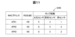
図11は、第4実施形態の到達範囲テーブルを示す図である。第4実施形態では、送信先のアクセスポイント40との間の受信信号強度(RSSI:Received Signal Strength Indication)に基づいて、情報源毎に、到達範囲がホップ段数で定められている。アクセスポイント20のフラッシュROM220は、RSSIとホップ段数との関係を、情報源毎に示すRSSIテーブル(図示しない)を備える。情報共有制御部212は、情報共有専用のSSIDが設定されたビーコンを受信した時に、アクセスポイント40との間のRSSIを取得し、RSSIテーブルを参照して、到達範囲テーブル224Eを作成する。到達範囲テーブル224Eの作成や更新は、定期スキャンによって実行されてもよい。なお、本実施形態でも、第2実施形態と同様に、到達範囲テーブル224Eには、受信した情報の共有要否が記載されておらず、到達範囲テーブル224Eとは別に、共有要否テーブルを備える。
FIG. 11 is a diagram illustrating a reachable range table according to the fourth embodiment. In the fourth embodiment, the reach range is determined by the number of hops for each information source based on the received signal strength (RSSI: Received Signal Strength Indication) with the destination access point 40. The
第4実施形態のネットワークシステムにおける機器情報共有時の処理において、第1実施形態と異なる部分について説明する。第4実施形態のアクセスポイント20は、第1実施形態のアクセスポイント20と同様に、図5のステップS202〜204の処理を行い、ステップS206では、共有要否テーブルを参照して、受信したデータが、機器情報共有対象の情報か否かを判別する。共有制御部212は、ステップS208において、到達範囲テーブル224Eを参照して送信先毎に到達範囲(ホップ段数)を決定する。情報共有制御部212は、送信先毎に、共有する情報(共有機器情報)と到達範囲(ホップ段数)を含む共有情報データを生成し、送信する(ステップS210)。例えば、共有する情報が火災センサの情報の場合、アクセスポイント41宛の共有情報データは、到達範囲として「ホップ段数=5」を含み、アクセスポイント42,43宛の共有情報データは、到達範囲として「ホップ段数=8」を含む。第4実施形態のアクセスポイント40における受信・中継処理は、第1実施形態と同様であるため、説明を省略する。
In the processing at the time of device information sharing in the network system of the fourth embodiment, a different part from the first embodiment will be described. Similar to the
第4実施形態のアクセスポイント20によれば、共有情報データの到達範囲を、送信先のアクセスポイント40との間のRSSIに基づいて定めているため、直接無線接続可能なアクセスポイント40との通信環境に応じて、情報を共有する範囲を制限することができる。このようにしても、共有する情報の到達範囲を適切に制限することができる。
According to the
E.変形例:
本発明は、先述の実施形態に限られるものではなく、その趣旨を逸脱しない範囲において種々の構成で実現することができる。例えば、発明の概要の欄に記載した各形態中の技術的特徴に対応する実施形態中の技術的特徴は、先述の課題の一部または全部を解決するために、あるいは、先述の効果の一部または全部を達成するために、適宜、差し替えや組み合わせを行うことが可能である。また、その技術的特徴が本明細書中に必須なものとして説明されていなければ、適宜、削除することが可能である。例えば、例えば次のような変形も可能である。
E. Variations:
The present invention is not limited to the above-described embodiment, and can be realized with various configurations without departing from the spirit of the present invention. For example, the technical features in the embodiments corresponding to the technical features in each embodiment described in the summary section of the invention are intended to solve part or all of the above-described problems or to achieve one of the effects described above. In order to achieve part or all, replacement and combination can be appropriately performed. Further, if the technical feature is not described as essential in the present specification, it can be deleted as appropriate. For example, the following modifications are possible, for example.
E−1.変形例1:
上記実施形態において、アクセスポイント20は、自LAN(第1の通信ネットワークNT1)に含まれる機器30からの情報を、他のLAN(第2の通信ネットワークNT2等)と共有する構成を例示したが、共有する情報は、自LAN内の情報に限定されない。例えば、Zigbee(登録商標)やZ−Wave(登録商標)等による無線通信、USBやHDMI(登録商標)などのバス接続による有線通信によって構成されるPAN(Personal Area Network)等における情報が共有されてもよい。また、アクセスポイント20がインターネットINTを介して通信端末90等から受信した情報を、他のLAN(第2の通信ネットワークNT2)に提供する構成にしてもよい。例えば、インターネットINTを介して受信された、自然災害(竜巻、雷、台風等)の情報が、第2の通信ネットワークNT2に含まれるアクセスポイント40に送信されてももよい。このようにすると、自然災害等の情報を早急に知覚する可能性を高めることができる。
E-1. Modification 1:
In the above embodiment, the
E−2.変形例2:
上記実施形態では、情報が到達する範囲を制限する例を示したが、アクセスポイント間の直接無線接続を介して制限無く情報が転送されていく構成にしてもよい。例えば、自然災害の情報等は、制限せずより広い範囲で情報を共有することで、被害の拡大を抑制する可能性を高めることができる。
E-2. Modification 2:
In the above-described embodiment, an example in which the range in which information reaches can be limited has been described. However, the information may be transferred without limitation via a direct wireless connection between access points. For example, it is possible to increase the possibility of suppressing the spread of damage by sharing information on natural disasters in a wider range without restriction.
E−3.変形例3:
上記実施形態では、到達範囲を、アクセスポイント20(発信元)からのホップ段数、距離、住所で指定する例を示したが、これに限定されない。例えば、到達範囲は、アクセスポイント20の経緯度に対して、経緯度の上下限値(例えば、±1分等)で指定されてもよい。複数種類の条件を組み合わせて指定されてもよく、例えば、距離と住所を組み合わせて、アクセスポイント20から距離○kmかつ××町内、アクセスポイント20から距離○kmまたは××町内等といったように到達範囲が指定されてもよい。また、到達範囲は、情報源からの情報に加えて、他の特定情報を加味して決定されてもよい。例えば、情報源が火災センサの場合に、予め定められたアクセスポイント20からの距離に加えて、風向き、風速等の特定情報を考慮して、方角に応じて到達範囲の距離が増減されてもよい。このようにしても、それぞれの情報に応じて適切に情報の共有範囲を制限することができる。また、上記実施形態では、情報源(センサ)毎に到達範囲が指定されているが、到達範囲を情報源毎に分けなくてもよい。すなわち、全ての情報源について同一の到達範囲内に共有機器情報が転送されてもよい。
E-3. Modification 3:
In the above embodiment, an example in which the reach range is specified by the number of hop stages from the access point 20 (source), the distance, and the address is shown, but the present invention is not limited to this. For example, the reach range may be specified by the upper and lower limits of the longitude and latitude (for example, ± 1 minute) with respect to the longitude and latitude of the
E−4.変形例4:
上記実施形態において、共有する機器情報として、防犯センサ、火災センサ、雨センサによる検知情報を例示したが、これらに限定されず、適宜、共有する情報が設定されてよい。例えば、アクセスポイント20が第1の通信ネットワークNT1に含まれる複数の機器30における使用電力量を集計し、使用電力量を共有してもよく、使用水道料、使用ガス量等を共有してもよい。このようにすると、ピークシフト、省エネ意識の向上に資することができる。また、例えば、人感センサ、離床センサ等からの検知情報を共有してもよい。人感センサや離床センサの情報を、近隣で共有することにより、例えば、徘徊する認知症の高齢者等の保護の早期化を図ることができる。また、ペット、農作物、家畜等の状態をセンサにより監視し、その監視情報を近隣で共有することにより、相互支援を可能にすることもできる。センサの方式は、赤外線、超音波、可視光、温度、静電容量等、種々の方式のセンサを利用することができる。
E-4. Modification 4:
In the said embodiment, although the detection information by a security sensor, a fire sensor, and a rain sensor was illustrated as apparatus information to share, it is not limited to these, Information to share may be set suitably. For example, the
E−5.変形例5:
上記実施形態において、さらに、共有情報データを受信したアクセスポイントにおいて、受信した情報を利用するか否かを判断する工程を備えてもよい。予め、利用する情報と利用しない情報をユーザが設定し、利用しないと設定された情報を受信した場合には、中継はするものの、報知はしなくてもよい。例えば、日中在宅者がない家庭の第2の通信ネットワークNT2において、雨センサの情報は利用しないという設定を行うことができる。このようにすることにより、自身が必要な情報のみを利用することができる。また、例えば、ホップ段数に基づいて、利用の要否を決定する構成にしてもよい。例えば、発信元で設定されたホップ段数と、受信時のホップ段数とに基づいて、発信元が遠くて利用する必要がないと判断した場合には、利用しなくてもよい。
E-5. Modification 5:
In the above embodiment, the access point that has received the shared information data may further include a step of determining whether or not to use the received information. When a user sets information to be used and information not to be used in advance and receives information set not to be used, the information is relayed but not notified. For example, in the second communication network NT2 in a home where there is no resident in the daytime, it is possible to perform setting so that rain sensor information is not used. By doing so, only the information necessary for itself can be used. Further, for example, it may be configured to determine the necessity of use based on the number of hop stages. For example, when it is determined that the source does not need to be used at a distance based on the number of hops set at the source and the number of hops at the time of reception, it may not be used.
E−6.変形例6:
上記実施形態において、無線接続装置として、アクセスポイントを例示したが、アクセスポイントに限定されず、他のLANに含まれる特定の他の機器と、直接無線接続が可能な無線接続装置であればよい。例えば、メッシュ機能を有するルーター、通信端末(コンピュータ)等であってもよい。
E-6. Modification 6:
In the above-described embodiment, the access point is exemplified as the wireless connection device. However, the wireless connection device is not limited to the access point, and may be any wireless connection device that can directly connect to other specific devices included in other LANs. . For example, a router having a mesh function, a communication terminal (computer), or the like may be used.
E−7.変形例7:
上記実施形態における無線接続装置としてのアクセスポイント20、41、42、43、51、52、53および60は、内部電源を備える移動可能な無線接続装置であっても良い。たとえば、内部電源としてバッテリを備え、バッテリからの給電によって無線通信を行うモバイル端末の特定機能として実現されても良い。モバイル端末としては、スマートフォン、モバイルルータといった無線データの送受信が可能な端末が含まれる。これらのモバイル端末は、移動体に搭載され現在位置を動的に変更して共有情報を生成・送信、あるいは送信された共有情報を受信・中継することができると共に、移動体が停止している場合には、停止位置にて共有情報の生成・送信、あるいは送信された共有情報を受信・中継を行うことができる。移動体としては、地上を移動する自転車、自動二輪、自動車といった地上移動体、気球、ヘリコプター、無人機(ドローン)といった空中移動体が含まれる。空中移動体にアクセスポイント機能を持たせることによって共有情報をホップしたり、地上移動体が共有情報送信時におけるホップに含ませることができる。なお、移動体とモバイル端末とは別体であっても良く、モバイル端末機能が移動体に組み込まれ一体、すなわち、通信機能を有する移動体、とされていても良い。
E-7. Modification 7:
The access points 20, 41, 42, 43, 51, 52, 53 and 60 as wireless connection devices in the above embodiment may be movable wireless connection devices having an internal power supply. For example, it may be realized as a specific function of a mobile terminal that includes a battery as an internal power supply and performs wireless communication by power feeding from the battery. Mobile terminals include terminals capable of transmitting and receiving wireless data, such as smartphones and mobile routers. These mobile terminals are mounted on a mobile unit and can dynamically change the current position to generate and transmit shared information, or receive and relay the transmitted shared information, and the mobile unit is stopped. In this case, the shared information can be generated / transmitted at the stop position, or the transmitted shared information can be received / relayed. Examples of the moving body include ground moving bodies such as bicycles, motorcycles, and automobiles that move on the ground, and air moving bodies such as balloons, helicopters, and drones. By giving an access point function to an airborne mobile body, shared information can be hopped, or a ground mobile body can be included in a hop when transmitting shared information. Note that the mobile body and the mobile terminal may be separate, and the mobile terminal function may be integrated into the mobile body, that is, a mobile body having a communication function.
無線接続装置が移動可能であることによって、たとえば、移動先における気候情報、交通情報、大気情報等を取得し共有情報を生成することが可能となる。また、無線接続装置が存在しない領域に無線接続装置を配置して一時的なアクセスポイントを実現し、意図しない途切れのない共有情報の送信、中継を実現することができる。 When the wireless connection device is movable, for example, it is possible to acquire climate information, traffic information, atmospheric information, and the like at the destination and generate shared information. Further, it is possible to realize a temporary access point by arranging a wireless connection device in an area where no wireless connection device exists, and to realize transmission and relay of unintentional uninterrupted shared information.
変形例7における移動可能な無線接続装置が用いられる場合、無線接続装置の現在位置に応じて、共有情報の送信を行わなかったり、共有情報の受信・中継を行わないようにしても良い。たとえば、移動可能な無線接続装置の現在位置が機密情報の確保が必要な予め定められた特定位置に含まれる場合、そのような現在位置において収集された情報に基づき生成された共有情報の送信や、そのような現在位置における生成された共有情報の受信・中継は行われるべきでないことがある。特定位置としては、たとえば、各国公館といった建造物や、たとえば国防施設といった地域・領域の位置に隣接または範囲に含まれる場合、そのような現在位置において収集された情報に基づき生成された共有情報の送信や、そのような現在位置において生成された共有情報の受信・中継は行われるべきでないことがある。これら建造物および地域の位置情報は地図データベースを利用して、その経度緯度情報によって特定することが可能であり、移動可能な無線接続装置は、たとえばGPS信号を介して、あるいは、無線基地局、無線アクセスポイントからの電波を利用する三角測量により、もしくは、無線基地局、無線アクセスポイントの位置情報を利用して、特定した自身の現在位置が予め定められた特定位置に含まれるか否かを判断することができる。 When the movable wireless connection apparatus in the modified example 7 is used, the shared information may not be transmitted, or the shared information may not be received / relayed according to the current position of the wireless connection apparatus. For example, when the current position of the movable wireless connection device is included in a predetermined specific position where confidential information needs to be secured, transmission of shared information generated based on information collected at such current position, In some cases, reception / relay of the generated shared information at the current position should not be performed. Specific locations include, for example, the structure of shared information generated based on the information collected at the current location when it is adjacent or within the scope of a building such as a national diplomatic mission or a region / region such as a defense facility. Transmission and reception / relay of shared information generated at such a current location may not be performed. The location information of these buildings and regions can be specified by the longitude and latitude information using a map database, and the movable wireless connection device can be, for example, via a GPS signal or a wireless base station, Whether or not the specified current position is included in a predetermined specific position by triangulation using radio waves from the wireless access point, or using the position information of the wireless base station or the wireless access point. Judgment can be made.
図12および図13を参照して、変形例7におけるアクセスポイント20における送信処理、および受信・中継処理について説明する。図12は変形例7に係るアクセスポイントの現在位置に応じて送信処理を行うか否かの判別処理ステップが加えられた図5のフローチャートの一部を示すフローチャートである。図13は変形例7に係るアクセスポイントの現在位置に応じて受信・中継処理を行うか否かの判別処理ステップが加えられた図6のフローチャートの一部を示すフローチャートである。
With reference to FIG. 12 and FIG. 13, transmission processing and reception / relay processing at the
図12の説明に際しては、各種情報源のうち、防犯センサ32からデータを受信する場合について例示的に説明するが、火災センサ34、エアコンといった他の情報源からのデータを受信する場合にも同様である。図12における、防犯センサ32からの情報は共有対象の情報であるとの判別の後(ステップS206:YES)、情報共有制御部212は、アクセスポイント20の現在位置は予め定められた特定位置に含まれるか否かを判別する(ステップS207)。情報共有制御部212は、アクセスポイント20の現在位置が予め定められた特定位置に含まれると判断すると(ステップS207:YES)、ステップS202に移行して各センサからのデータの入力を待機する。情報共有制御部212は、アクセスポイント20の現在位置が予め定められた特定位置に含まれないと判断すると(ステップS207:NO)、到達範囲テーブル224Aを参照して、防犯センサに対応するホップ段数を抽出する(ステップS208)。ステップS207以外のステップにおける詳細な説明は図5を用いて説明済みであるから省略する。なお、図12のフローチャートでは共有対象の情報であるとの判断(ステップS206:YES)の後に、特定位置に含まれるか否かを判断しているが(ステップS207)、共有対象の情報であるか否かにかかわらず(ステップS206の判断を行うことなく)、特定位置に含まれるか否かを判断し、特定位置に含まれない場合に(ステップS207:NO)送信処理を行ってもよく、特定位置に含まれる場合に(ステップS207:YES)送信処理を行わなくてもよい。
In the description of FIG. 12, the case of receiving data from the
図13の説明に際しては、図12の説明を受けて防犯センサ32からのデータ受信に基づく共有情報を用いる例について説明するが、火災センサ34、エアコン36等からのデータに基づく共有情報を用いる場合についても同様である。図13において、アクセスポイント41の情報共有制御部412が、Idle状態において、アクセスポイント20から上述の共有情報データを受信すると(ステップS302)、情報共有制御部412は、アクセスポイント41の現在位置は予め定められた特定位置に含まれるか否かを判別する(ステップS303)。情報共有制御部412は、アクセスポイント41の現在位置が予め定められた特定位置に含まれると判断すると(ステップS303:YES)、受信した共有情報データを破棄して(ステップS310)、Idle状態に戻る(ステップS302)。情報共有制御部412は、アクセスポイント41の現在位置が予め定められた特定位置に含まれないと判断すると(ステップS303:NO)、ステップS304に移行する。ステップS303以外のステップにおける詳細な説明は図6を用いて説明済みであるから省略する。また、この処理は、他のアクセスポイントから共有情報を受信し、更に他のアクセスポイントに対して共有情報を中継するアクセスポイントにおいて実行され得る処理であり、アクセスポイント41以外のアクセスポイント42、43、51〜53および60においても同様の処理が実行され得る。
In the description of FIG. 13, an example of using shared information based on data reception from the
なお、図13のフローチャートでは特定位置に含まれないことの判断(S303:NO)の後に、ホップ段数が0でない場合(S304:NO)に中継処理を行っているが、ホップ段数が0であるか否かにかかわらず(ステップS304の判断を行うことなく)、特定位置に含まれるか否かを判断し、特定位置に含まれない場合に(ステップS303:NO)中継処理を行ってもよく、特定位置に含まれる場合に(ステップS303:YES)中継処理を行わなくてもよい。すなわち、アクセスポイント41の情報共有制御部412は、受信した共有情報を修正することなく、中継処理(ステップS306)を実行しても良い。アクセスポイント41が移動可能なアクセスポイントの場合、その存在を予め想定することができず、アクセスポイント41においてホップ段数を減じることによって所期のホップ段数を実現することができなくなる可能性がある。そこで、アクセスポイント41が移動可能なアクセスポイントである場合には、ホップ段数を減らす処理、すなわち、共有情報の修正処理を実行することなく中継処理を行っても良い。 In the flowchart of FIG. 13, the relay process is performed when the hop stage number is not 0 (S304: NO) after the determination that it is not included in the specific position (S303: NO), but the hop stage number is 0. Regardless of whether or not it is included in the specific position (without performing the determination in step S304), if it is not included in the specific position (step S303: NO), the relay process may be performed. When included in the specific position (step S303: YES), the relay process may not be performed. That is, the information sharing control unit 412 of the access point 41 may execute the relay process (step S306) without correcting the received shared information. When the access point 41 is a movable access point, the existence of the access point 41 cannot be assumed in advance, and there is a possibility that the intended hop number cannot be realized by reducing the number of hops at the access point 41. Therefore, when the access point 41 is a movable access point, the relay process may be performed without executing the process of reducing the number of hops, that is, the shared information correction process.
20,41,42,43,51,52,53,60…アクセスポイント
30…機器
32…防犯センサ
34…火災センサ
36…エアコン
38…雨センサ
90…通信端末
100…ネットワークシステム
210…CPU
212…情報共有制御部
214…LAN制御部
222…位置情報
224A,B,D,E…到達範囲テーブル
225…変換テーブル
228…プロトコルスタック
240…情報共有インターフェース
250…WANインターフェース
260…LANインターフェース
220…フラッシュROM
AS1,AS2…到達範囲
NT1…第1の通信ネットワーク
NT2…第2の通信ネットワーク
NT3…第3の通信ネットワーク
NT4…第4の通信ネットワーク
INT…インターネット
20, 41, 42, 43, 51, 52, 53, 60 ...
212 ... Information
AS1, AS2 ... reach NT1 ... first communication network NT2 ... second communication network NT3 ... third communication network NT4 ... fourth communication network INT ... internet
Claims (14)
前記他の無線接続装置のうち特定の無線接続装置との間で、前記直接無線通信により、共有情報を授受するための情報共有インターフェースと、
前記無線接続装置に接続されている1以上の機器から受信した情報から、共有情報の生成に用いられるべき種別の異なる機器である情報源を判別し、判別した情報源を用いて特定の情報を選択し、選択した特定の情報を用いて前記共有情報を生成し、前記情報共有インターフェースを介して、前記特定の無線接続装置に送信する情報共有制御部と、
を備える、無線接続装置。 A wireless connection device capable of direct wireless communication with other wireless connection devices,
An information sharing interface for exchanging shared information by direct wireless communication with a specific wireless connection device among the other wireless connection devices;
From information received from one or more devices connected to the wireless connection device , an information source that is a device of a different type to be used for generating shared information is determined, and specific information is determined using the determined information source. An information sharing control unit that selects, generates the shared information using the selected specific information, and transmits the shared information to the specific wireless connection device via the information sharing interface;
A wireless connection device.
前記情報源は検知機器および家電機器を含み、
前記情報共有制御部は、前記情報源が前記検知機器である場合に、前記共有情報を生成する、無線接続装置。 The wireless connection device according to claim 1,
The information sources include sensing devices and home appliances,
The information sharing control unit is a wireless connection device that generates the shared information when the information source is the detection device.
前記情報共有制御部は、さらに、前記共有情報を到達させる到達範囲を設定し、設定された前記到達範囲に関する情報を前記共有情報に含ませる、無線接続装置。 The wireless connection device according to claim 1 or 2,
The information sharing control unit further sets a reachable range in which the shared information is reached, and includes information related to the set reachable range in the shared information.
前記到達範囲は、住所、ホップ段数、距離、および経緯度の少なくとも1つに基づいて決定される、無線接続装置。 The wireless connection device according to claim 3,
The reachable range is determined by at least one of an address, the number of hops, a distance, and a longitude and latitude.
前記到達範囲は、前記特定の情報毎に決定される、無線接続装置。 The wireless connection device according to claim 3 or 4,
The reachable range is a wireless connection device that is determined for each specific information.
前記特定の情報は、気象センサ、地震センサ、防犯センサ、火災センサの少なくともいずれか一つから受信した情報を含む、無線接続装置。 The wireless connection device according to any one of claims 1 to 5,
The specific information includes a wireless connection device including information received from at least one of a weather sensor, an earthquake sensor, a security sensor, and a fire sensor.
前記情報共有制御部は、さらに、
前記無線接続装置が、インターネットを介して受信した情報から前記特定の情報を選択して、前記共有情報を生成し、前記情報共有インターフェースを介して、前記特定の無線接続装置に送信する、
無線接続装置。 In the wireless connection device according to any one of claims 1 to 6,
The information sharing control unit further includes:
The wireless connection device selects the specific information from information received via the Internet, generates the shared information, and transmits the shared information to the specific wireless connection device via the information sharing interface.
Wireless connection device.
前記無線接続装置には、内部電源を有し移動可能な無線接続装置が含まれる、無線接続装置。 The wireless connection device according to any one of claims 1 to 7,
The wireless connection device includes a wireless connection device having an internal power supply and movable.
前記情報共有制御部は、
前記特定の無線接続装置から前記情報共有インターフェースを介して受信した前記共有情報を修正し、前記情報共有インターフェースを介して、前記特定の無線接続装置とは異なる他の特定の無線接続装置に送信する、
無線接続装置。 The wireless connection device according to any one of claims 1 to 7,
The information sharing control unit
The shared information received from the specific wireless connection device via the information sharing interface is modified and transmitted to another specific wireless connection device different from the specific wireless connection device via the information sharing interface. ,
Wireless connection device.
前記無線接続装置には、内部電源を有し移動可能な無線接続装置が含まれ、
前記移動可能な無線接続装置が備える前記情報共有制御部は、前記移動可能な無線接続装置の現在位置が予め定められた特定位置に含まれる場合には、修正した前記共有情報を前記他の特定の無線接続装置に送信しない、無線接続装置。 The wireless connection device according to claim 10,
The wireless connection device includes a movable wireless connection device having an internal power supply,
The information sharing control unit included in the movable wireless connection device, when the current position of the movable wireless connection device is included in a predetermined specific position, the corrected shared information is included in the other specific information. Wireless connection device that does not transmit to other wireless connection devices.
前記無線接続装置には、内部電源を有し移動可能な無線接続装置が含まれ、
前記移動可能な無線接続装置が備える前記情報共有制御部は、前記移動可能な無線接続装置の現在位置が予め定められた特定位置に含まれる場合には、前記特定の無線接続装置から前記情報共有インターフェースを介して受信した前記共有情報を、前記情報共有インターフェースを介して、前記特定の無線接続装置とは異なる他の特定の無線接続装置に送信しない、
無線接続装置。 The wireless connection device according to any one of claims 1 to 7,
The wireless connection device includes a movable wireless connection device having an internal power supply,
The information sharing control unit included in the movable wireless connection device may share the information from the specific wireless connection device when a current position of the movable wireless connection device is included in a predetermined specific position. The shared information received via the interface is not transmitted to another specific wireless connection device different from the specific wireless connection device via the information sharing interface.
Wireless connection device.
前記第1の無線接続装置は、
前記第2の無線接続装置との間で、前記直接無線通信により、共有情報を授受するための情報共有インターフェースと、
前記第1の無線接続装置に接続された1以上の機器から受信した情報から、共有情報の生成に用いられるべき種別の異なる機器である情報源を判別し、判別した情報源を用いて特定の情報を選択し、選択した特定の情報を用いて前記共有情報を生成し、前記情報共有インターフェースを介して、前記第2の無線接続装置に送信する情報共有制御部と、
を備える、ネットワークシステム。 A network system comprising: a first wireless connection device; and a second wireless connection device capable of direct wireless communication with the first wireless connection device,
The first wireless connection device is:
An information sharing interface for exchanging shared information with the second wireless connection device through the direct wireless communication;
From information received from one or more devices connected to the first wireless connection device , an information source that is a device of a different type to be used for generating shared information is determined, and a specific information source is determined using the determined information source. An information sharing control unit that selects information, generates the shared information using the selected specific information, and transmits the shared information to the second wireless connection device via the information sharing interface;
A network system comprising:
前記無線接続装置に接続されている1以上の機器から受信した情報から、共有情報の生成に用いられるべき種別の異なる機器である情報源を判別し、判別した情報源を用いて特定の情報を選択し、
前記特定の情報に基づいて共有情報を生成し、
前記無線接続装置とは異なる、特定の無線接続装置と、直接、無線接続を確立し、
前記共有情報を、前記無線接続が確立された前記特定の無線接続装置に対して送信すること、
を備える、無線接続装置の制御方法。 A method for controlling a wireless connection device, comprising:
From information received from one or more devices connected to the wireless connection device , an information source that is a device of a different type to be used for generating shared information is determined, and specific information is determined using the determined information source. Selected,
Generating shared information based on the specific information;
A direct wireless connection is established with a specific wireless connection device, which is different from the wireless connection device,
Transmitting the shared information to the specific wireless connection device with which the wireless connection is established;
A method for controlling a wireless connection device.
Priority Applications (2)
| Application Number | Priority Date | Filing Date | Title |
|---|---|---|---|
| JP2015103667A JP6572625B2 (en) | 2014-06-20 | 2015-05-21 | Wireless connection apparatus, network system, and wireless connection apparatus control method |
| US14/743,597 US10368338B2 (en) | 2014-06-20 | 2015-06-18 | Wireless device, network system and control method of wireless device |
Applications Claiming Priority (3)
| Application Number | Priority Date | Filing Date | Title |
|---|---|---|---|
| JP2014126925 | 2014-06-20 | ||
| JP2014126925 | 2014-06-20 | ||
| JP2015103667A JP6572625B2 (en) | 2014-06-20 | 2015-05-21 | Wireless connection apparatus, network system, and wireless connection apparatus control method |
Publications (2)
| Publication Number | Publication Date |
|---|---|
| JP2016021732A JP2016021732A (en) | 2016-02-04 |
| JP6572625B2 true JP6572625B2 (en) | 2019-09-11 |
Family
ID=54870937
Family Applications (1)
| Application Number | Title | Priority Date | Filing Date |
|---|---|---|---|
| JP2015103667A Active JP6572625B2 (en) | 2014-06-20 | 2015-05-21 | Wireless connection apparatus, network system, and wireless connection apparatus control method |
Country Status (2)
| Country | Link |
|---|---|
| US (1) | US10368338B2 (en) |
| JP (1) | JP6572625B2 (en) |
Families Citing this family (11)
| Publication number | Priority date | Publication date | Assignee | Title |
|---|---|---|---|---|
| US9619996B1 (en) * | 2014-08-14 | 2017-04-11 | Kyle B. Smith | Distributed wild fire alert system |
| US10063416B2 (en) * | 2015-06-05 | 2018-08-28 | Honeywell International Inc. | Bidirectional redundant mesh networks |
| MX2018010226A (en) | 2016-02-26 | 2018-11-19 | Amazon Tech Inc | Sharing video footage from audio/video recording and communication devices. |
| US10748414B2 (en) | 2016-02-26 | 2020-08-18 | A9.Com, Inc. | Augmenting and sharing data from audio/video recording and communication devices |
| US10397528B2 (en) | 2016-02-26 | 2019-08-27 | Amazon Technologies, Inc. | Providing status information for secondary devices with video footage from audio/video recording and communication devices |
| US11393108B1 (en) | 2016-02-26 | 2022-07-19 | Amazon Technologies, Inc. | Neighborhood alert mode for triggering multi-device recording, multi-camera locating, and multi-camera event stitching for audio/video recording and communication devices |
| US10841542B2 (en) | 2016-02-26 | 2020-11-17 | A9.Com, Inc. | Locating a person of interest using shared video footage from audio/video recording and communication devices |
| JP6957142B2 (en) * | 2016-11-08 | 2021-11-02 | 株式会社東芝 | Control device, wireless communication device and channel control method |
| JP6869066B2 (en) * | 2017-03-22 | 2021-05-12 | 大阪瓦斯株式会社 | Alarm system |
| JP6902766B2 (en) * | 2018-03-30 | 2021-07-14 | サイレックス・テクノロジー株式会社 | Communication equipment, communication control methods, and communication systems |
| JP2023094417A (en) * | 2021-12-23 | 2023-07-05 | パナソニックIpマネジメント株式会社 | Alarm system, alarm cooperation system, cooperation method, and program |
Family Cites Families (20)
| Publication number | Priority date | Publication date | Assignee | Title |
|---|---|---|---|---|
| CA2477962C (en) * | 2002-03-01 | 2013-07-16 | Enterasys Networks, Inc. | Location aware data network |
| US8239942B2 (en) * | 2002-12-30 | 2012-08-07 | Cisco Technology, Inc. | Parallel intrusion detection sensors with load balancing for high speed networks |
| US20040246906A1 (en) * | 2003-06-06 | 2004-12-09 | Hardy William Christopher | Methods and systems for accelerating inference engines used in expert systems |
| US7119675B2 (en) * | 2004-01-27 | 2006-10-10 | Matsushita Electric Industrial Co., Ltd. | Emergency alert service |
| KR100612496B1 (en) * | 2004-05-11 | 2006-08-14 | 삼성전자주식회사 | Method for service discovery in Mobile Ad-hoc Network |
| JP4622546B2 (en) * | 2005-01-31 | 2011-02-02 | パナソニック株式会社 | COMMUNICATION METHOD AND RADIO COMMUNICATION DEVICE |
| JP2008543185A (en) * | 2005-05-27 | 2008-11-27 | シンボリック インテリジェンス エンハンスト システムズ, インコーポレイテッド | Cell television broadcasting system |
| US20070002736A1 (en) * | 2005-06-16 | 2007-01-04 | Cisco Technology, Inc. | System and method for improving network resource utilization |
| JP4792948B2 (en) * | 2005-12-02 | 2011-10-12 | アイシン・エィ・ダブリュ株式会社 | Inter-vehicle communication system |
| US8199885B2 (en) * | 2007-05-21 | 2012-06-12 | At&T Intellectual Property I, L.P. | Method and apparatus for transmitting emergency messages |
| US8406162B2 (en) * | 2008-05-16 | 2013-03-26 | La Crosse Technology, Ltd. | Method and apparatus of transmitting, receiving, displaying and playing weather data |
| JP4881366B2 (en) * | 2008-12-03 | 2012-02-22 | ヤフー株式会社 | Method and system for transmitting emergency information to other houses |
| US8155044B2 (en) * | 2009-01-21 | 2012-04-10 | Mitsubishi Electric Research Laboratories, Inc. | Method for broadcasting alert message in mobile multi-hop networks using inferred distance prioritization |
| JP5888803B2 (en) | 2011-02-09 | 2016-03-22 | ミサワホーム株式会社 | Building, server device, building system |
| JP5724592B2 (en) * | 2011-04-28 | 2015-05-27 | 株式会社Jvcケンウッド | Imaging apparatus, imaging data sharing system, and program |
| JP5703474B2 (en) * | 2011-08-25 | 2015-04-22 | 株式会社日立製作所 | Communication system and communication method |
| JP6022786B2 (en) | 2012-03-26 | 2016-11-09 | ホーチキ株式会社 | Alarm linkage system |
| JP6027310B2 (en) | 2011-10-31 | 2016-11-16 | ホーチキ株式会社 | Alarm linkage system |
| JP2013168761A (en) * | 2012-02-15 | 2013-08-29 | Panasonic Corp | Information communication terminal and information communication system |
| US8811363B2 (en) * | 2012-09-11 | 2014-08-19 | Wavemax Corp. | Next generation network services for 3G/4G mobile data offload in a network of shared protected/locked Wi-Fi access points |
-
2015
- 2015-05-21 JP JP2015103667A patent/JP6572625B2/en active Active
- 2015-06-18 US US14/743,597 patent/US10368338B2/en active Active
Also Published As
| Publication number | Publication date |
|---|---|
| JP2016021732A (en) | 2016-02-04 |
| US10368338B2 (en) | 2019-07-30 |
| US20150373553A1 (en) | 2015-12-24 |
Similar Documents
| Publication | Publication Date | Title |
|---|---|---|
| JP6572625B2 (en) | Wireless connection apparatus, network system, and wireless connection apparatus control method | |
| JP6239819B2 (en) | Alarm linkage system | |
| Verma et al. | MANET based emergency communication system for natural disasters | |
| JP6238511B2 (en) | Regional disaster prevention information system | |
| Álvarez et al. | Bluemergency: Mediating post-disaster communication systems using the internet of things and bluetooth mesh | |
| TWI508609B (en) | Network configuration method and wireless networking system | |
| JP3775430B2 (en) | Network service information providing system, network service information providing apparatus and method, and operation control method thereof | |
| KR20150134687A (en) | LED street light system using Wireless Mesh Network | |
| JP2015211251A (en) | Network system, and wireless connection device | |
| CN108076435A (en) | A kind of reversed personnel location system based on Internet of Things | |
| JP2022174205A (en) | Wireless sensor system and communication control method | |
| JP2010081456A (en) | Radio communication system, call processing control device and call processing control method | |
| JPWO2010137614A1 (en) | Wireless LAN access point device, mobile communication terminal, communication method and program | |
| JP2007295349A (en) | Communication relay system and method | |
| JP2011109337A (en) | Communication system | |
| Wirtz et al. | Enabling ubiquitous interaction with smart things | |
| JP6341976B2 (en) | Regional disaster prevention information system | |
| JP6341977B2 (en) | Regional disaster prevention information system | |
| Ashraf et al. | WiMesh: leveraging mesh networking for disaster communication in resource-constrained settings | |
| JP2015142241A (en) | Wireless communication system, wireless terminal, and wireless communication method | |
| JP4609067B2 (en) | Specific area entry / exit detection system, location information control server, and location information control program | |
| KR101512745B1 (en) | Plug and play sensor network system using peer-to-peer communication and method for providing application service using the system | |
| JP2018129598A (en) | Positional information management system and portable device used for the same | |
| JP2017092944A (en) | Connection setting device and method thereof | |
| JP2008172459A (en) | Security system |
Legal Events
| Date | Code | Title | Description |
|---|---|---|---|
| A621 | Written request for application examination |
Free format text: JAPANESE INTERMEDIATE CODE: A621 Effective date: 20180124 |
|
| A977 | Report on retrieval |
Free format text: JAPANESE INTERMEDIATE CODE: A971007 Effective date: 20181113 |
|
| A131 | Notification of reasons for refusal |
Free format text: JAPANESE INTERMEDIATE CODE: A131 Effective date: 20181127 |
|
| A521 | Request for written amendment filed |
Free format text: JAPANESE INTERMEDIATE CODE: A523 Effective date: 20190123 |
|
| A131 | Notification of reasons for refusal |
Free format text: JAPANESE INTERMEDIATE CODE: A131 Effective date: 20190507 |
|
| A521 | Request for written amendment filed |
Free format text: JAPANESE INTERMEDIATE CODE: A523 Effective date: 20190626 |
|
| TRDD | Decision of grant or rejection written | ||
| A01 | Written decision to grant a patent or to grant a registration (utility model) |
Free format text: JAPANESE INTERMEDIATE CODE: A01 Effective date: 20190716 |
|
| A61 | First payment of annual fees (during grant procedure) |
Free format text: JAPANESE INTERMEDIATE CODE: A61 Effective date: 20190729 |
|
| R150 | Certificate of patent or registration of utility model |
Ref document number: 6572625 Country of ref document: JP Free format text: JAPANESE INTERMEDIATE CODE: R150 |
|
| R250 | Receipt of annual fees |
Free format text: JAPANESE INTERMEDIATE CODE: R250 |
|
| R250 | Receipt of annual fees |
Free format text: JAPANESE INTERMEDIATE CODE: R250 |