JP6571026B2 - Journal bearing and rotating machine - Google Patents
Journal bearing and rotating machine Download PDFInfo
- Publication number
- JP6571026B2 JP6571026B2 JP2016036926A JP2016036926A JP6571026B2 JP 6571026 B2 JP6571026 B2 JP 6571026B2 JP 2016036926 A JP2016036926 A JP 2016036926A JP 2016036926 A JP2016036926 A JP 2016036926A JP 6571026 B2 JP6571026 B2 JP 6571026B2
- Authority
- JP
- Japan
- Prior art keywords
- region
- bearing
- rotor shaft
- bearing pad
- oil
- Prior art date
- Legal status (The legal status is an assumption and is not a legal conclusion. Google has not performed a legal analysis and makes no representation as to the accuracy of the status listed.)
- Active
Links
Images


Classifications
-
- F—MECHANICAL ENGINEERING; LIGHTING; HEATING; WEAPONS; BLASTING
- F16—ENGINEERING ELEMENTS AND UNITS; GENERAL MEASURES FOR PRODUCING AND MAINTAINING EFFECTIVE FUNCTIONING OF MACHINES OR INSTALLATIONS; THERMAL INSULATION IN GENERAL
- F16C—SHAFTS; FLEXIBLE SHAFTS; ELEMENTS OR CRANKSHAFT MECHANISMS; ROTARY BODIES OTHER THAN GEARING ELEMENTS; BEARINGS
- F16C17/00—Sliding-contact bearings for exclusively rotary movement
- F16C17/02—Sliding-contact bearings for exclusively rotary movement for radial load only
- F16C17/03—Sliding-contact bearings for exclusively rotary movement for radial load only with tiltably-supported segments, e.g. Michell bearings
-
- F—MECHANICAL ENGINEERING; LIGHTING; HEATING; WEAPONS; BLASTING
- F01—MACHINES OR ENGINES IN GENERAL; ENGINE PLANTS IN GENERAL; STEAM ENGINES
- F01D—NON-POSITIVE DISPLACEMENT MACHINES OR ENGINES, e.g. STEAM TURBINES
- F01D25/00—Component parts, details, or accessories, not provided for in, or of interest apart from, other groups
- F01D25/16—Arrangement of bearings; Supporting or mounting bearings in casings
- F01D25/162—Bearing supports
-
- F—MECHANICAL ENGINEERING; LIGHTING; HEATING; WEAPONS; BLASTING
- F02—COMBUSTION ENGINES; HOT-GAS OR COMBUSTION-PRODUCT ENGINE PLANTS
- F02C—GAS-TURBINE PLANTS; AIR INTAKES FOR JET-PROPULSION PLANTS; CONTROLLING FUEL SUPPLY IN AIR-BREATHING JET-PROPULSION PLANTS
- F02C7/00—Features, components parts, details or accessories, not provided for in, or of interest apart form groups F02C1/00 - F02C6/00; Air intakes for jet-propulsion plants
- F02C7/06—Arrangements of bearings; Lubricating
-
- F—MECHANICAL ENGINEERING; LIGHTING; HEATING; WEAPONS; BLASTING
- F16—ENGINEERING ELEMENTS AND UNITS; GENERAL MEASURES FOR PRODUCING AND MAINTAINING EFFECTIVE FUNCTIONING OF MACHINES OR INSTALLATIONS; THERMAL INSULATION IN GENERAL
- F16C—SHAFTS; FLEXIBLE SHAFTS; ELEMENTS OR CRANKSHAFT MECHANISMS; ROTARY BODIES OTHER THAN GEARING ELEMENTS; BEARINGS
- F16C17/00—Sliding-contact bearings for exclusively rotary movement
- F16C17/02—Sliding-contact bearings for exclusively rotary movement for radial load only
- F16C17/022—Sliding-contact bearings for exclusively rotary movement for radial load only with a pair of essentially semicircular bearing sleeves
-
- F—MECHANICAL ENGINEERING; LIGHTING; HEATING; WEAPONS; BLASTING
- F16—ENGINEERING ELEMENTS AND UNITS; GENERAL MEASURES FOR PRODUCING AND MAINTAINING EFFECTIVE FUNCTIONING OF MACHINES OR INSTALLATIONS; THERMAL INSULATION IN GENERAL
- F16C—SHAFTS; FLEXIBLE SHAFTS; ELEMENTS OR CRANKSHAFT MECHANISMS; ROTARY BODIES OTHER THAN GEARING ELEMENTS; BEARINGS
- F16C19/00—Bearings with rolling contact, for exclusively rotary movement
- F16C19/50—Other types of ball or roller bearings
- F16C19/507—Other types of ball or roller bearings with rolling elements journaled in one of the moving parts, e.g. stationary rollers to support a rotating part
-
- F—MECHANICAL ENGINEERING; LIGHTING; HEATING; WEAPONS; BLASTING
- F16—ENGINEERING ELEMENTS AND UNITS; GENERAL MEASURES FOR PRODUCING AND MAINTAINING EFFECTIVE FUNCTIONING OF MACHINES OR INSTALLATIONS; THERMAL INSULATION IN GENERAL
- F16C—SHAFTS; FLEXIBLE SHAFTS; ELEMENTS OR CRANKSHAFT MECHANISMS; ROTARY BODIES OTHER THAN GEARING ELEMENTS; BEARINGS
- F16C33/00—Parts of bearings; Special methods for making bearings or parts thereof
- F16C33/02—Parts of sliding-contact bearings
- F16C33/04—Brasses; Bushes; Linings
- F16C33/046—Brasses; Bushes; Linings divided or split, e.g. half-bearings or rolled sleeves
-
- F—MECHANICAL ENGINEERING; LIGHTING; HEATING; WEAPONS; BLASTING
- F16—ENGINEERING ELEMENTS AND UNITS; GENERAL MEASURES FOR PRODUCING AND MAINTAINING EFFECTIVE FUNCTIONING OF MACHINES OR INSTALLATIONS; THERMAL INSULATION IN GENERAL
- F16C—SHAFTS; FLEXIBLE SHAFTS; ELEMENTS OR CRANKSHAFT MECHANISMS; ROTARY BODIES OTHER THAN GEARING ELEMENTS; BEARINGS
- F16C33/00—Parts of bearings; Special methods for making bearings or parts thereof
- F16C33/02—Parts of sliding-contact bearings
- F16C33/04—Brasses; Bushes; Linings
- F16C33/06—Sliding surface mainly made of metal
- F16C33/10—Construction relative to lubrication
- F16C33/1025—Construction relative to lubrication with liquid, e.g. oil, as lubricant
- F16C33/103—Construction relative to lubrication with liquid, e.g. oil, as lubricant retained in or near the bearing
-
- F—MECHANICAL ENGINEERING; LIGHTING; HEATING; WEAPONS; BLASTING
- F16—ENGINEERING ELEMENTS AND UNITS; GENERAL MEASURES FOR PRODUCING AND MAINTAINING EFFECTIVE FUNCTIONING OF MACHINES OR INSTALLATIONS; THERMAL INSULATION IN GENERAL
- F16C—SHAFTS; FLEXIBLE SHAFTS; ELEMENTS OR CRANKSHAFT MECHANISMS; ROTARY BODIES OTHER THAN GEARING ELEMENTS; BEARINGS
- F16C33/00—Parts of bearings; Special methods for making bearings or parts thereof
- F16C33/02—Parts of sliding-contact bearings
- F16C33/04—Brasses; Bushes; Linings
- F16C33/06—Sliding surface mainly made of metal
- F16C33/10—Construction relative to lubrication
- F16C33/1025—Construction relative to lubrication with liquid, e.g. oil, as lubricant
- F16C33/106—Details of distribution or circulation inside the bearings, e.g. details of the bearing surfaces to affect flow or pressure of the liquid
- F16C33/1065—Grooves on a bearing surface for distributing or collecting the liquid
-
- F—MECHANICAL ENGINEERING; LIGHTING; HEATING; WEAPONS; BLASTING
- F16—ENGINEERING ELEMENTS AND UNITS; GENERAL MEASURES FOR PRODUCING AND MAINTAINING EFFECTIVE FUNCTIONING OF MACHINES OR INSTALLATIONS; THERMAL INSULATION IN GENERAL
- F16C—SHAFTS; FLEXIBLE SHAFTS; ELEMENTS OR CRANKSHAFT MECHANISMS; ROTARY BODIES OTHER THAN GEARING ELEMENTS; BEARINGS
- F16C9/00—Bearings for crankshafts or connecting-rods; Attachment of connecting-rods
- F16C9/02—Crankshaft bearings
-
- F—MECHANICAL ENGINEERING; LIGHTING; HEATING; WEAPONS; BLASTING
- F16—ENGINEERING ELEMENTS AND UNITS; GENERAL MEASURES FOR PRODUCING AND MAINTAINING EFFECTIVE FUNCTIONING OF MACHINES OR INSTALLATIONS; THERMAL INSULATION IN GENERAL
- F16C—SHAFTS; FLEXIBLE SHAFTS; ELEMENTS OR CRANKSHAFT MECHANISMS; ROTARY BODIES OTHER THAN GEARING ELEMENTS; BEARINGS
- F16C33/00—Parts of bearings; Special methods for making bearings or parts thereof
- F16C33/02—Parts of sliding-contact bearings
- F16C33/04—Brasses; Bushes; Linings
- F16C33/06—Sliding surface mainly made of metal
- F16C33/10—Construction relative to lubrication
- F16C33/1025—Construction relative to lubrication with liquid, e.g. oil, as lubricant
- F16C33/1045—Details of supply of the liquid to the bearing
Description
本開示は、ロータ軸を回転可能に支持するためのジャーナル軸受および回転機械に関する。 The present disclosure relates to a journal bearing and a rotating machine for rotatably supporting a rotor shaft.
一般に、蒸気タービンやガスタービン等の回転機械に用いられる軸受装置として、ジャーナル軸受が知られている。
例えば特許文献1には、複数の軸受パッドによってロータ軸を支持するジャーナル軸受が記載されている。具体的には、特許文献1のジャーナル軸受は、キャリアリングと、キャリアリングに支持される上流側軸受パッド及び下流側軸受パッドと、各軸受パッドとロータ軸との間に潤滑油を供給する複数の給油ノズルと、を備えている。複数の給油ノズルは、上流側軸受パッドよりも上流側に配置された第1の給油ノズル(最上流ノズル)と、上流側軸受パッドの両端部に配置された第2及び第3の給油ノズルと、下流側軸受パッドの上流側端部に配置された第4の給油ノズルと、を含む。また、下半部キャリアリングの両端面にはサイドプレートが配置されており、給油ノズルから供給された潤滑油の軸受外部への漏出を抑制するようになっている。
In general, journal bearings are known as bearing devices used in rotating machines such as steam turbines and gas turbines.
For example,
ところで、特許文献1に記載されるように複数の軸受パッドを備えるジャーナル軸受においては、正常動作時、回転数の上昇に伴ってロータ軸と各軸受パッドの間にそれぞれ適正な厚さの油膜が形成され、これらの油膜圧力によってロータ軸が略直上に浮き上がるようになっている。
しかしながら、本発明者らの知見によれば、複数の軸受パッド間における負荷能力の適正なバランスを維持できないために、軸受性能が低下したり、異常振動が発生したりすることが起こり得る。例えば、上流側軸受パッドにおける油膜圧力が不足して上流側領域での十分な負荷能力を確保できず、ロータ軸が浮上する際に上流側へ寄ってしまうと、このことが異常振動の発生原因になり得る。
Incidentally, in a journal bearing having a plurality of bearing pads as described in
However, according to the knowledge of the present inventors, it is not possible to maintain an appropriate balance of load capacity among a plurality of bearing pads, so that it is possible that the bearing performance deteriorates or abnormal vibration occurs. For example, if the oil film pressure at the upstream bearing pad is insufficient and sufficient load capacity in the upstream region cannot be secured, and the rotor shaft moves to the upstream side when it floats, this may cause abnormal vibration. Can be.
上述の事情に鑑みて、本発明の少なくとも一実施形態は、複数の軸受パッド間における負荷能力のバランスを維持し、異常振動の発生を防止するとともに軸受性能を向上し得るジャーナル軸受および回転機械を提供することを目的とする。 In view of the above circumstances, at least one embodiment of the present invention provides a journal bearing and a rotating machine that can maintain a balance of load capacity among a plurality of bearing pads, prevent occurrence of abnormal vibration, and improve bearing performance. The purpose is to provide.
(1)本発明の少なくとも幾つかの実施形態に係るジャーナル軸受は、
キャリアリングと、
前記キャリアリングの下半領域の内周側に設けられ、ロータ軸を下方から支持するように構成された複数の軸受パッドと、
前記ロータ軸の軸方向における前記複数の軸受パッドの両側に設けられる一対のサイドプレートと、を備え、
各々の前記サイドプレートは、
前記複数の軸受パッドのうち最上流側に位置する第1軸受パッドの上流側の周方向範囲を含む第1領域と、
前記第1領域の上流側に位置し、前記サイドプレートの内周面と前記ロータ軸の外周面との間の間隔が前記第1領域よりも大きい第2領域と、
を含む。
(1) A journal bearing according to at least some embodiments of the present invention includes:
With carrier ring,
A plurality of bearing pads provided on the inner peripheral side of the lower half region of the carrier ring and configured to support the rotor shaft from below;
A pair of side plates provided on both sides of the plurality of bearing pads in the axial direction of the rotor shaft,
Each said side plate
A first region including a circumferential range on the upstream side of the first bearing pad located on the most upstream side among the plurality of bearing pads;
A second region located on the upstream side of the first region, wherein the distance between the inner peripheral surface of the side plate and the outer peripheral surface of the rotor shaft is larger than the first region;
including.
本発明者らによる鋭意検討の結果、最上流側に位置する第1軸受パッド(上流側軸受パッド)とロータ軸との間の油膜圧力が不足する原因として、第1軸受パッドにキャリーオーバされる潤滑油への空気の混入があることを見出した。
すなわち、各々のサイドプレートの内周面とロータ軸の外周面との間に、一対のサイドプレートによって囲まれた軸受内部空間と軸受外部とを連通させるための隙間を有するジャーナル軸受では、下流側に配置された第2軸受パッド(下流側軸受パッド)から第1軸受パッドに至る領域で該隙間から吸い込まれた空気が潤滑油に混入し得る。このため、第1軸受パッドにキャリーオーバされる潤滑油(以下、キャリーオーバ油と称する)には多くの空気が含まれ、実質の潤滑油の油量が少ないと考えられる。したがって、第1軸受パッドの上流側直前の給油ユニットと、第2軸受パッドの上流側直前の給油ユニットとの吐出油量が同じであっても、第2軸受パッドに比べて第1軸受パッドでは潤滑油不足となりやすい。また、潤滑油は非圧縮性流体であるのに対して、潤滑油に含まれる空気は圧縮性流体であるため、上流側の第1軸受パッド(特に前縁近傍)において潤滑油に含まれる気泡が押しつぶされ、第1軸受パッドの前縁側において動圧が生じにくくなる。
これにより、第1軸受パッドの負荷能力が低下し、複数の軸受パッド間における負荷能力の適正なバランスが維持できなくなる。そのため、回転数の上昇に伴いロータ軸の軸心軌跡が鉛直線上から逸れてしまい、異常振動が発生したり、軸受性能が低下したりする可能性が高くなる。
As a result of intensive studies by the present inventors, the oil film pressure between the first bearing pad (upstream bearing pad) located on the most upstream side and the rotor shaft is insufficient, and the first bearing pad carries over. It was found that air was mixed into the lubricating oil.
That is, in a journal bearing having a gap between the inner peripheral surface of each side plate and the outer peripheral surface of the rotor shaft for communicating the bearing inner space surrounded by the pair of side plates and the outer bearing, In the region from the second bearing pad (downstream bearing pad) arranged at the first bearing pad to the first bearing pad, the air sucked from the gap can be mixed into the lubricating oil. For this reason, it is considered that the lubricating oil carried over to the first bearing pad (hereinafter referred to as “carryover oil”) contains a large amount of air, and the amount of substantial lubricating oil is small. Therefore, even if the amount of oil discharged from the oil supply unit immediately upstream of the first bearing pad and the oil supply unit immediately upstream of the second bearing pad are the same, the first bearing pad has a larger amount than the second bearing pad. Prone to lack of lubricating oil. In addition, since the lubricating oil is an incompressible fluid, the air contained in the lubricating oil is a compressive fluid. Therefore, the air bubbles contained in the lubricating oil in the first bearing pad on the upstream side (particularly near the front edge). Is crushed, and dynamic pressure is less likely to occur on the front edge side of the first bearing pad.
As a result, the load capacity of the first bearing pad is lowered, and an appropriate balance of the load capacity among the plurality of bearing pads cannot be maintained. Therefore, as the rotational speed increases, the axis of the rotor shaft deviates from the vertical line, and there is a high possibility that abnormal vibration will occur or bearing performance will deteriorate.
そこで、上記(1)のジャーナル軸受では、各々のサイドプレートが、複数の軸受パッドのうち最上流側に位置する第1軸受パッドの上流側の周方向範囲を含む第1領域と、第1領域の上流側に位置し、サイドプレートとロータ軸との間(具体的にはサイドプレートの内周面とロータ軸の外周面との間)の間隔が第1領域よりも大きい第2領域と、を含む構成となっている。
この構成において、サイドプレートの第2領域とロータ軸との間の間隔は比較的広いので、第2領域の周方向範囲において潤滑油は排出されやすい。そのため、回転するロータ軸に連れまわって第1領域側へ向けて搬送されるキャリーオーバ油は、第1領域に到達する前にその大部分がジャーナル軸受の外部へ排出される。
また、サイドプレートの第1領域とロータ軸との間の間隔は比較的狭いので、第1領域の周方向範囲においては潤滑油が排出され難い。そのため、一対のサイドプレートの各第1領域とロータ軸とで囲まれる空間、すなわち第1軸受パッドの上流側の空間に、潤滑油の油溜まりが形成される。この油溜まりからの潤滑油が第1軸受パッドとロータ軸との間の隙間に流れ込んで油膜を形成するため、この油膜に気泡が含有することを抑制でき、第1軸受パッドにおける油膜圧力を十分に高く維持することができる。なお、上述したように第2領域の周方向範囲においてキャリーオーバ油はその大部分が排出されるので、油溜まりまで到達するキャリーオーバ油を少なくすることができ、これによっても油溜まりの潤滑油に混入する空気量を低減できる。
これらのことから、複数の軸受パッド間における負荷能力のバランスを適正に保つことができ、ジャーナル軸受における異常振動の発生防止および軸受性能の向上が図れる。
Therefore, in the journal bearing of the above (1), each side plate includes a first region including a circumferential range on the upstream side of the first bearing pad located on the most upstream side among the plurality of bearing pads, and a first region. A second region in which the distance between the side plate and the rotor shaft (specifically, between the inner peripheral surface of the side plate and the outer peripheral surface of the rotor shaft) is larger than the first region, It is the composition which includes.
In this configuration, since the distance between the second region of the side plate and the rotor shaft is relatively wide, the lubricating oil is easily discharged in the circumferential range of the second region. Therefore, most of the carry-over oil that is transported toward the first region along with the rotating rotor shaft is discharged outside the journal bearing before reaching the first region.
Further, since the distance between the first region of the side plate and the rotor shaft is relatively narrow, it is difficult for the lubricating oil to be discharged in the circumferential range of the first region. Therefore, an oil sump for lubricating oil is formed in a space surrounded by the first regions of the pair of side plates and the rotor shaft, that is, a space on the upstream side of the first bearing pad. Since the lubricating oil from this oil pool flows into the gap between the first bearing pad and the rotor shaft to form an oil film, it is possible to suppress the inclusion of bubbles in this oil film, and the oil film pressure at the first bearing pad is sufficient. Can be kept high. As described above, most of the carry-over oil is discharged in the circumferential range of the second region, so that it is possible to reduce the carry-over oil that reaches the oil sump. The amount of air mixed in can be reduced.
For these reasons, it is possible to maintain an appropriate balance of load capacity among the plurality of bearing pads, and to prevent occurrence of abnormal vibration in the journal bearing and improve bearing performance.
(2)幾つかの実施形態では、上記(1)の構成において、
前記第2領域の周方向範囲内において前記キャリアリングの内周側に、前記キャリアリングから径方向内方に向かって突出して設けられ、キャリーオーバ油の下流側への流れを抑制するように構成された少なくとも一つのキャリーオーバ抑制部をさらに備える。
(2) In some embodiments, in the configuration of (1) above,
Within the circumferential range of the second region, provided on the inner circumferential side of the carrier ring so as to protrude radially inward from the carrier ring, and configured to suppress the flow of carryover oil to the downstream side And at least one carry-over suppressing unit.
上記(2)の構成によれば、第2領域の周方向範囲内においてキャリアリングの内周側に、キャリアリングから径方向内方に向かって突出したキャリーオーバ抑制部が設けられている。このキャリーオーバ抑制部によって、キャリーオーバ油が第2領域よりも下流側へ流れることが抑制されるので、第1領域の周方向範囲に形成された油溜まりに流入するキャリーオーバ油量を低減することができる。よって、第1軸受パッドとロータ軸との間の油膜に空気が混入することをより効果的に抑制できる。 According to the configuration of (2) above, the carry-over suppressing portion that protrudes radially inward from the carrier ring is provided on the inner peripheral side of the carrier ring within the circumferential range of the second region. Since the carry-over suppressing unit suppresses the carry-over oil from flowing downstream from the second region, the amount of carry-over oil flowing into the oil reservoir formed in the circumferential range of the first region is reduced. be able to. Therefore, it can suppress more effectively that air mixes into the oil film between a 1st bearing pad and a rotor shaft.
(3)幾つかの実施形態では、上記(1)又は(2)の構成において、
前記第1領域の周方向範囲内において前記第1軸受パッドの上流側に設けられ、前記第1軸受パッドに潤滑油を供給するための少なくとも一本の第1給油ユニットをさらに備える。
(3) In some embodiments, in the above configuration (1) or (2),
It further includes at least one first oil supply unit that is provided on the upstream side of the first bearing pad within the circumferential range of the first region and supplies lubricating oil to the first bearing pad.
上記(3)の構成によれば、第1領域の周方向範囲内において第1軸受パッドの上流側に位置する第1給油ユニットによって、第1軸受パッドの上流側に確実に油溜まりを形成することができる。そのため、気泡の混入がない又は少ない油溜まりを第1軸受パッドの上流側に形成し、かかる油溜まりから第1軸受パッドに潤滑油を供給することで、潤滑油への気泡混入に起因した第1軸受パッドの負荷能力の低減を抑制することができる。 According to the configuration of (3) above, the oil reservoir is reliably formed on the upstream side of the first bearing pad by the first oil supply unit located on the upstream side of the first bearing pad within the circumferential range of the first region. be able to. For this reason, an oil sump with no or little bubbles is formed on the upstream side of the first bearing pad, and the lubricating oil is supplied from the oil sump to the first bearing pad. Reduction of the load capacity of one bearing pad can be suppressed.
(4)幾つかの実施形態では、上記(1)乃至(3)の何れかの構成において、
前記第2領域の周方向範囲内において、前記複数の軸受パッドのうち最下流側に位置する第2軸受パッドの下流側に設けられ、前記第2軸受パッドの後縁側に潤滑油を供給するための第2給油ユニットをさらに備える。
(4) In some embodiments, in any one of the above configurations (1) to (3),
In order to supply lubricating oil to the rear edge side of the second bearing pad, provided on the downstream side of the second bearing pad located on the most downstream side among the plurality of bearing pads within the circumferential range of the second region. The second oil supply unit is further provided.
上記(4)の構成のように、第2給油ユニットが、最下流側パッド(第2軸受パッド)よりも下流側に設けられている場合、第2給油ユニットから第2軸受パッドの後縁側に供給された潤滑油は、キャリーオーバ油として第1軸受パッド側へ搬送されやすい。この点、上記(4)の構成では、第2給油ユニットが第2領域の周方向範囲内に設けられているので、第2給油ユニットから供給された潤滑油の大部分は、サイドプレートとロータ軸との間の隙間から外部へ排出される。そのため、第2給油ユニットから供給された潤滑油がキャリーオーバ油として第1軸受パッドまで到達することを抑制できる。 When the second oil supply unit is provided on the downstream side of the most downstream pad (second bearing pad) as in the configuration of (4) above, the second oil supply unit is provided on the rear edge side of the second bearing pad. The supplied lubricating oil is easily conveyed to the first bearing pad side as carry-over oil. In this regard, in the configuration of (4) above, since the second oil supply unit is provided in the circumferential range of the second region, most of the lubricating oil supplied from the second oil supply unit is made up of the side plate and the rotor. It is discharged outside through the gap between the shaft. Therefore, the lubricating oil supplied from the second oil supply unit can be prevented from reaching the first bearing pad as carry-over oil.
(5)幾つかの実施形態では、上記(1)乃至(4)の何れかの構成において、
前記第1領域の下流側端は、前記第1軸受パッドの後縁よりも下流側に位置する。
(5) In some embodiments, in any one of the above configurations (1) to (4),
The downstream end of the first region is located downstream of the rear edge of the first bearing pad.
上記(5)の構成によれば、第1軸受パッドの上流側及び該第1軸受パッドの周方向範囲内ではサイドプレートとロータ軸との間の間隔が比較的狭いので、油溜まりおよび第1軸受パッドに保持される潤滑油量を十分に確保することができる。よって、第1軸受パッドにおける油膜圧力を高く維持することができる。 According to the configuration of (5) above, since the distance between the side plate and the rotor shaft is relatively narrow on the upstream side of the first bearing pad and in the circumferential range of the first bearing pad, the oil reservoir and the first A sufficient amount of lubricating oil can be secured on the bearing pad. Therefore, the oil film pressure at the first bearing pad can be maintained high.
(6)幾つかの実施形態では、上記(1)乃至(5)の何れかの構成において、
前記第1領域の下流側端および前記第2領域の上流側端の角度位置θは、前記複数の軸受パッドのうち最下流側に位置する第2軸受パッドの張り角をαとし、前記第2軸受パッドの後縁の角度位置をθTEとしたとき、θTE−0.25α≦θ≦θTE+0.25αを満たす。
(6) In some embodiments, in any one of the above configurations (1) to (5),
The angular position θ of the downstream end of the first region and the upstream end of the second region is defined as α, where the tension angle of the second bearing pad located on the most downstream side among the plurality of bearing pads is α. when the angular position of the trailing edge of the bearing pad and theta TE, satisfy θ TE -0.25α ≦ θ ≦ θ TE + 0.25α.
上記(6)の構成では、第1領域の下流側端および第2領域の上流側端が、複数の軸受パッドのうち最下流側に位置する第2軸受パッドの後縁付近に位置している。すなわち、サイドプレートとロータ軸との間の隙間が比較的狭い第1領域の周方向範囲が、複数の軸受パッドが設けられた領域を概ねカバーしており、各軸受パッドに保持される潤滑油量を十分に確保できる。また、サイドプレートとロータ軸との間の隙間が比較的広い第2領域の周方向範囲が、第2軸受パッドの後縁付近から始まっている。そのため、第2軸受パッドの直ぐ下流側において、第2領域におけるサイドプレートとロータ軸との間の比較的広い隙間から潤滑油を排出することで、キャリーオーバ油を効果的に減らすことができる。 In the configuration of (6) above, the downstream end of the first region and the upstream end of the second region are located near the rear edge of the second bearing pad located on the most downstream side among the plurality of bearing pads. . That is, the circumferential range of the first region in which the gap between the side plate and the rotor shaft is relatively narrow substantially covers the region where the plurality of bearing pads are provided, and the lubricating oil retained by each bearing pad. A sufficient amount can be secured. In addition, the circumferential range of the second region in which the gap between the side plate and the rotor shaft is relatively wide starts from the vicinity of the rear edge of the second bearing pad. Therefore, the carry-over oil can be effectively reduced by discharging the lubricating oil from the relatively wide gap between the side plate and the rotor shaft in the second region immediately downstream of the second bearing pad.
(7)幾つかの実施形態では、上記(1)乃至(6)の何れかの構成において、
各々の前記サイドプレートは、前記間隔が第1間隔で一定である前記第1領域を形成する下半部と、前記間隔が第2間隔で一定である前記第2領域を形成する上半部と、を含む。
(7) In some embodiments, in any one of the configurations (1) to (6) above,
Each of the side plates includes a lower half portion that forms the first region in which the interval is constant at the first interval, and an upper half portion that forms the second region in which the interval is constant at the second interval. ,including.
上記(7)の構成では、一対のサイドプレートのそれぞれが、上半部および下半部を含む半割構造となっている。そのため、各サイドプレートの製造および取付けの作業性向上が図れる。なお、上半部及び下半部が占める角度範囲は特に限定されないが、例えば、上半部及び下半部がそれぞれ180度の角度範囲にわたって設けられていてもよい。
また、上半部および下半部は、それぞれ、ロータ軸との間に一定の隙間を形成するようになっており、上半部とロータ軸の間の第1隙間と、下半部とロータ軸の間の第2隙間とは間隔が異なっている。すなわち、第1領域を形成する下半部と、第2領域を形成する上半部とは別体で形成されているため、間隔の異なる第1隙間および第2隙間の調整が容易である。
In the configuration of (7) above, each of the pair of side plates has a halved structure including an upper half and a lower half. Therefore, the workability of manufacturing and mounting each side plate can be improved. In addition, although the angle range which an upper half part and a lower half part occupy is not specifically limited, For example, the upper half part and the lower half part may be provided over the angle range of 180 degree | times, respectively.
In addition, the upper half and the lower half each form a certain gap between the rotor shaft and the first half between the upper half and the rotor shaft, and the lower half and the rotor. The distance is different from the second gap between the shafts. That is, since the lower half forming the first region and the upper half forming the second region are formed separately, it is easy to adjust the first gap and the second gap having different intervals.
(8)一実施形態では、上記(7)の構成において、
各々の前記サイドプレートは、前記下半部と前記上半部との接合面が水平面に対して傾斜している。
(8) In one embodiment, in the configuration of (7) above,
In each of the side plates, a joint surface between the lower half and the upper half is inclined with respect to a horizontal plane.
上記(8)の構成によれば、各軸受パッド、油溜まり、および軸受内部空間と外部空間とを連通する隙間のそれぞれの配置の自由度を向上させることができる。
またこの構成において、下半部の上流側の方がその下流側よりも上方に位置するように各々のサイドプレートを配置すれば、第1軸受パッドの直ぐ上流側における第1領域の延設範囲を広げることができ、第1軸受パッドの上流側における油溜まりが形成される領域を拡大できる。一方、最下流側パッドの直ぐ下流側まで第2領域の延設範囲を広げることができ、最下流側パッドの直ぐ下流側において、ロータ軸とサイドプレートとの間の隙間から潤滑油を外部に排出し、キャリーオーバ油を効果的に減らすことができる。
According to the configuration of (8) above, it is possible to improve the degree of freedom of arrangement of each bearing pad, the oil sump, and the gap that connects the bearing internal space and the external space.
Further, in this configuration, if each side plate is arranged so that the upstream side of the lower half is positioned higher than the downstream side, the extending range of the first region immediately upstream of the first bearing pad. And the region where the oil sump is formed on the upstream side of the first bearing pad can be enlarged. On the other hand, the extension range of the second region can be expanded to the downstream side of the most downstream pad, and the lubricating oil is released to the outside from the gap between the rotor shaft and the side plate on the downstream side of the most downstream pad. Drain and carry-over oil can be reduced effectively.
(9)一実施形態では、上記(8)の構成において、
前記接合面の前記水平面に対する傾斜角は、5度以上45度以下である。
(9) In one embodiment, in the configuration of (8) above,
The inclination angle of the joint surface with respect to the horizontal plane is not less than 5 degrees and not more than 45 degrees.
上記(9)の構成によれば、サイドプレートの上半部及び下半部の接合面の傾斜角を上記範囲内に設定することで、第1領域及び第2領域を適切に配置し、第1軸受パッドの上流側の油溜まり領域を広く確保するとともに、最下流側パッドの直ぐ下流側における潤滑油の排出を促進し、キャリーオーバ油を効果的に減らすことができる。 According to the configuration of (9) above, the first region and the second region are appropriately arranged by setting the inclination angles of the joint surfaces of the upper half and the lower half of the side plate within the above range, It is possible to secure a wide oil reservoir region on the upstream side of one bearing pad, promote the discharge of lubricating oil immediately downstream of the most downstream pad, and effectively reduce carry-over oil.
(10)幾つかの実施形態では、上記(1)乃至(9)の何れかの構成において、
前記第1領域における前記間隔をG1とし、前記第2領域における前記間隔をG2とし、前記サイドプレートの内径をDとしたとき、G1≦0.01D、且つ、G2≧0.02Dを満たす。
(10) In some embodiments, in any one of the above configurations (1) to (9),
Wherein the distance in the first region and G 1, wherein the interval in the second region and G 2, when the inner diameter of the side plate was D, G 1 ≦ 0.01D, and, G 2 ≧ 0.02D Meet.
上記(10)の構成によれば、第1領域におけるサイドプレートの内周面とロータ軸の外周面との間隔をG1と、第2領域におけるサイドプレートの内周面とロータ軸の外周面との間隔をG2とを、上記範囲内に設定することにより、油溜まりの形成およびキャリーオーバ油の排出をより効果的に行うことができる。 According to the above configuration (10), the distance between the inner and outer circumferential surfaces of the rotor shaft of the side plate in the first region and the G 1, the outer peripheral surface of the inner peripheral surface and the rotor shaft of the side plate in the second region the distance between the G 2, by setting in the above range, it is possible to perform the formation and discharge of carry-over oil reservoir oil more effectively.
(11)幾つかの実施形態では、上記(1)乃至(10)の何れかの構成において、
各々の前記サイドプレートは、隣接する一対の前記軸受パッド間の周方向位置において、潤滑油を排出するための少なくとも一つの開口を有する。
(11) In some embodiments, in any one of the above configurations (1) to (10),
Each of the side plates has at least one opening for discharging lubricating oil at a circumferential position between a pair of adjacent bearing pads.
上記(11)の構成によれば、軸受パッド間において開口から潤滑油が排出されるので、軸受パッド間に潤滑油が溜まってロータ軸の撹拌抵抗が増大してしまうことを回避できる。 According to the configuration (11), since the lubricating oil is discharged from the openings between the bearing pads, it can be avoided that the lubricating oil accumulates between the bearing pads and the stirring resistance of the rotor shaft increases.
(12)本発明の少なくとも幾つかの実施形態に係る回転機械は、
上記(1)乃至(11)の何れか一に記載のジャーナル軸受と、
前記ジャーナル軸受によって支持されるロータ軸と、
を備える。
(12) A rotating machine according to at least some embodiments of the present invention includes:
The journal bearing according to any one of (1) to (11) above;
A rotor shaft supported by the journal bearing;
Is provided.
上記(12)の回転機械によれば、異常振動が発生しにくく且つ優れた軸受性能を有するジャーナル軸受を備えているので、信頼性の高い回転機械を提供することができる。 According to the rotating machine of the above (12), since the journal bearing that is unlikely to generate abnormal vibration and has excellent bearing performance is provided, a highly reliable rotating machine can be provided.
本発明の少なくとも一実施形態によれば、第2領域の周方向範囲においてキャリーオーバ油が積極的に軸受外部へ排出され、第1領域の周方向範囲において油溜まりが形成される。この油溜まりからの潤滑油が第1軸受パッドとロータ軸との間の隙間に流れ込んで油膜を形成するので、この油膜には気泡が殆ど含まれず、第1軸受パッドにおける油膜圧力を十分に高く維持することができる。よって、複数の軸受パッド間における負荷能力のバランスを適正に保つことができ、ジャーナル軸受における異常振動の発生防止および軸受性能の向上が図れる。 According to at least one embodiment of the present invention, carry-over oil is positively discharged outside the bearing in the circumferential range of the second region, and an oil reservoir is formed in the circumferential range of the first region. Since the lubricating oil from the oil pool flows into the gap between the first bearing pad and the rotor shaft to form an oil film, the oil film contains almost no bubbles, and the oil film pressure at the first bearing pad is sufficiently high. Can be maintained. Therefore, the balance of the load capacity among the plurality of bearing pads can be properly maintained, and the occurrence of abnormal vibration in the journal bearing can be prevented and the bearing performance can be improved.
以下、添付図面を参照して本発明の幾つかの実施形態について説明する。ただし、実施形態として記載されている又は図面に示されている構成部品の寸法、材質、形状、その相対的配置等は、本発明の範囲をこれに限定する趣旨ではなく、単なる説明例にすぎない。 Hereinafter, some embodiments of the present invention will be described with reference to the accompanying drawings. However, the dimensions, materials, shapes, relative arrangements, etc. of the components described in the embodiments or shown in the drawings are not intended to limit the scope of the present invention, but are merely illustrative examples. Absent.
最初に、図1〜図3を参照して、幾つかの実施形態に係るジャーナル軸受10の全体構成について説明する。
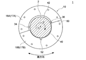
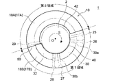
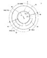
図1は、一実施形態に係るジャーナル軸受10の軸方向に沿った断面図である。図2は、図1のA−A線断面図である。図3は、図1のB−B矢視図である。なお、図2及び図3は、ロータ軸2の軸方向に直交する面を示している。
Initially, with reference to FIGS. 1-3, the whole structure of the journal bearing 10 which concerns on some embodiment is demonstrated.
FIG. 1 is a cross-sectional view along the axial direction of a journal bearing 10 according to an embodiment. 2 is a cross-sectional view taken along line AA in FIG. 3 is a BB arrow view of FIG. 2 and 3 show a plane orthogonal to the axial direction of the
本実施形態の説明において、「軸方向」は、ジャーナル軸受10に支持されるロータ軸2の中心軸線Oの方向であり、「径方向」はロータ軸2の半径方向であり、「周方向」はロータ軸2の周方向である。なお、「周方向」は、キャリアリング12,13の周方向であってもよいし、サイドプレート17,18の周方向であってもよい。さらに、本実施形態において「上流側」又は「下流側」とは、ロータ軸2の回転方向における上流側又は下流側のことを言う。
In the description of this embodiment, the “axial direction” is the direction of the central axis O of the
図1〜図3に示す実施形態において、ジャーナル軸受10は、潤滑方式(給油方式)として直接潤滑方式を採用した構成を備えており、下半領域に第1軸受パッド30及び第2軸受パッド32が配置された構成を有している。例えば、ジャーナル軸受10は、ティルティングパッド軸受である。
以下、図示されるジャーナル軸受10について例示的に説明するが、本実施形態に係るジャーナル軸受10はこの構成に限定されるものではない。例えば、他の実施形態においては、上半領域にもさらに2個の軸受パッドが配置され、周方向に計4個の軸受パッドが取り付けられた構成であってもよいし、下半領域に3個以上の軸受パッドが取り付けられた構成であってもよい。但し、何れの構成においても、ジャーナル軸受10の作動中は主として下半領域の軸受パッドがロータ軸2の荷重を支持するようになっている。
In the embodiment shown in FIGS. 1 to 3, the journal bearing 10 has a configuration in which a direct lubrication method is adopted as a lubrication method (oil supply method), and the
Hereinafter, the illustrated journal bearing 10 will be described as an example, but the journal bearing 10 according to the present embodiment is not limited to this configuration. For example, in another embodiment, two bearing pads may be arranged in the upper half region, and a total of four bearing pads may be attached in the circumferential direction. A configuration in which more than one bearing pad is attached may be used. However, in any configuration, the bearing pad in the lower half region mainly supports the load of the
幾つかの実施形態において、ジャーナル軸受10は、キャリアリング11と、キャリアリング11の下半領域の内周側に設けられ、ロータ軸2を下方から支持するように構成された複数の軸受パッド30,32と、ロータ軸2の軸方向における複数の軸受パッド30,32の両側に設けられる一対のサイドプレート17,18と、を備える。
In some embodiments, the journal bearing 10 is provided on the inner peripheral side of the
以下、ジャーナル軸受10の各部材の具体的な構成例について説明する。
キャリアリング11は、不図示の軸受ケーシングに支持されており、上半部キャリアリング12及び下半部キャリアリング13を含む。上半部キャリアリング12及び下半部キャリアリング13は、それぞれ、軸方向に直交する断面が半円弧状となるような内周面及び外周面を有している。なお、図示される例では、キャリアリング11が上半部キャリアリング12及び下半部キャリアリング13に分割された構成を示しているが、キャリアリング11は一体構造であってもよいし、3以上に分割された構成であってもよい。
Hereinafter, a specific configuration example of each member of the journal bearing 10 will be described.
The
キャリアリング11の軸方向の両端側には、ロータ軸2の外周に沿って、一対のサイドプレート17,18が配置されている。サイドプレート17,18は、円板状に形成されており、中央にロータ軸2が貫通する穴が形成されている。これらのサイドプレート17,18によって、後述する給油ユニット25〜29から供給される潤滑油の外部への漏出を適度に抑制するようになっている。
A pair of
図1に示すように、上半部キャリアリング12は、主としてロータ軸2の跳ね上がりを上方から押え込むために、内周面にガイドメタル(半円環軸受部)20,21が取り付けられていてもよい。例えば、上半部キャリアリング12の軸方向の両端側で且つサイドプレート17,18よりも軸方向において内側に、一対のガイドメタル20,21が取り付けられている。ガイドメタル20,21は、半円形状に形成されている。
このように、上半部キャリアリング12の内周側にガイドメタル20,21が設けられることで、ガイドメタル20,21によってロータ軸2の跳ね上がりを押さえ込むことができ、ロータ軸2の跳ね上がりによる部品の破損等を防止できる。なお、キャリアリング11が、上半部キャリアリング12及び下半部キャリアリング13に分割された構造ではなく一体構造である場合、あるいは3以上に分割された構造である場合、ガイドメタル20,21は、キャリアリング11の上半領域に設けられていればよい。
As shown in FIG. 1, the upper
Thus, by providing the
上半部キャリアリング12及び下半部キャリアリング13には、少なくとも一本の給油ユニット25〜29が設けられている。例えば、給油ユニット25〜29は、給油ノズルである。
図2に示す例では、ロータ軸2が図中矢印Sに示すように時計回りに回転する場合、ロータ軸2の回転方向Sにおいて上流側から給油ユニット(後述する第1給油ユニット)25、給油ユニット(後述する第1給油ユニット)26、給油ユニット27、給油ユニット28、給油(後述する第2給油ユニット)29を含む計5本の給油ユニットが設けられている。
具体的には、給油ユニット25,26は、最上流に位置する第1軸受パッド30よりも上流側に、周方向に並んで配置されている。給油ユニット27,28は、第1軸受パッド30と、該第1軸受パッド30よりも下流側に位置する第2軸受パッド32との間に、周方向に並んで配置されている。給油ユニット29は、第2軸受パッド32よりも下流側に配置されている。
The upper
In the example shown in FIG. 2, when the
Specifically, the
キャリアリング11の内部には、潤滑油供給路(不図示)が形成されている。潤滑油供給路に供給された潤滑油は各給油ユニット25〜29に送られて、各給油ユニット25〜29から軸受パッド30,32の近傍に噴出される。
A lubricating oil supply path (not shown) is formed inside the
第1軸受パッド30および第2軸受パッド32は、下半部キャリアリング13の内周側に設けられ、ロータ軸2を下方から支えるように構成されている。
第1軸受パッド30は、下半部キャリアリング13の内周側においてロータ軸2の外周に沿って設けられている。
第2軸受パッド32は、下半部キャリアリング13の内周側において第1軸受パッド30よりもロータ軸2の回転方向Sの下流側にロータ軸2の外周に沿って設けられている。
このように、下半部キャリアリング13に第1軸受パッド30および第2軸受パッド32が設けられているので、第1軸受パッド30および第2軸受パッド32によってロータ軸2を適切に支持できる。
The
The
The
Thus, since the
なお、キャリアリング11が、上半部キャリアリング12及び下半部キャリアリング13に分割された構造ではなく一体構造である場合、あるいは3以上に分割された構造である場合、第1軸受パッド30および第2軸受パッド32は、キャリアリング11の下半領域に設けられていればよい。
In addition, when the
次に、図2〜図6を参照して、サイドプレート17,18とのその周辺構造の具体的な構成について説明する。
なお、図4は、一実施形態に係るサイドプレート17,18及び給油ユニット25〜29を説明するための概略図である。図5は、一実施形態に係るサイドプレート17,18の構成を説明するための概略図である。図6は、一実施形態に係るサイドプレート17,18の他の構成を説明するための概略図である。図4〜図6は、何れも図3に対応した図であるが、これらの図においてキャリーオーバ抑制部34,36は省略している。
Next, with reference to FIGS. 2-6, the specific structure of the peripheral structure with the
FIG. 4 is a schematic diagram for explaining the
幾つかの実施形態に係るジャーナル軸受10では、図4〜図6に例示的に示すように、ロータ軸2の軸方向(中心軸線Oに沿った方向)における複数の軸受パッド30,32の両側に一対のサイドプレート17,18が設けられており、各々のサイドプレート17,18が、複数の軸受パッド30,32のうち最上流側に位置する第1軸受パッド30の上流側の周方向範囲を含む第1領域と、第1領域の上流側に位置し、サイドプレート17,18の内周面とロータ軸2の外周面との間の間隔が第1領域よりも大きい第2領域と、を含む。言い換えれば、このジャーナル軸受10では、各々のサイドプレート17,18の第2領域とロータ軸2との間の第2隙間42が、各々のサイドプレート17,18の第1領域とロータ軸2との間の第1隙間40よりも大きい。
In the journal bearing 10 according to some embodiments, as illustrated in FIGS. 4 to 6, both sides of the plurality of bearing
本発明者らによる鋭意検討の結果、最上流側に位置する第1軸受パッド30とロータ軸2との間の油膜圧力が不足する原因として、第1軸受パッド30にキャリーオーバされる潤滑油への空気の混入があることを見出した。
すなわち、各々のサイドプレート17,18の内周面とロータ軸2の外周面との間に、一対のサイドプレート17,18によって囲まれた軸受内部空間と軸受外部とを連通させるための隙間40,42を有するジャーナル軸受10では、下流側の第2軸受パッド32から上流側の第1軸受パッド30に至る領域で該隙間40,42から吸い込まれた空気が潤滑油に混入し得る。このため、第1軸受パッド30にキャリーオーバされる潤滑油には多くの空気が含まれ、実質の潤滑油の油量が少ないと考えられる。したがって、第1軸受パッド30の上流側直前の給油ユニット25,26と、第2軸受パッド32の上流側直前の給油ユニット27,28との吐出油量が同じであっても、第2軸受パッド32に比べて第1軸受パッド30では潤滑油不足となりやすい。また、潤滑油は非圧縮性流体であるのに対して、潤滑油に含まれる空気は圧縮性流体であるため、第1軸受パッド30(特に前縁近傍)において潤滑油に含まれる気泡が押しつぶされ、第1軸受パッド30の前縁30a側において動圧が生じにくくなる。
これにより、第1軸受パッド30の負荷能力が低下し、複数の軸受パッド30,32間における負荷能力の適正なバランスが維持できなくなる。そのため、回転数の上昇に伴いロータ軸2の軸心軌跡が鉛直線上から逸れてしまい、異常振動が発生したり、軸受性能が低下したりする可能性が高くなる。
As a result of intensive studies by the present inventors, the oil film pressure between the
In other words, a
As a result, the load capacity of the
そこで、上記実施形態に係るジャーナル軸受10では、各々のサイドプレート17,18が、複数の軸受パッド30,32のうち最上流側に位置する第1軸受パッド30の上流側の周方向範囲を含む第1領域と、第1領域の上流側に位置し、サイドプレート17,18とロータ軸2との間(具体的にはサイドプレート17,18の内周面とロータ軸2の外周面との間)の間隔が第1領域よりも大きい第2領域と、を含む構成となっている。
この構成において、サイドプレート17,18の第2領域とロータ軸2との間の間隔(第2隙間42)は比較的広いので、第2領域の周方向範囲において潤滑油は排出されやすい。そのため、回転するロータ軸2に連れまわって第1領域側へ向けて搬送されるキャリーオーバ油は、第1領域に到達する前にその大部分がジャーナル軸受10の外部へ排出される。
また、サイドプレート17,18の第1領域とロータ軸2との間の間隔は比較的狭いので、第1領域の周方向範囲においては潤滑油が排出され難い。そのため、一対のサイドプレート17,18の各第1領域とロータ軸2とで囲まれる空間、すなわち第1軸受パッド30の上流側の空間に、潤滑油の油溜まりが形成される。この油溜まりからの潤滑油が第1軸受パッド30とロータ軸2との間の隙間に流れ込んで油膜を形成するため、この油膜に気泡が含有することを抑制でき、第1軸受パッド30における油膜圧力を十分に高く維持することができる。なお、上述したように第2領域の周方向範囲においてキャリーオーバ油はその大部分が排出されるので、油溜まりまで到達するキャリーオーバ油を少なくすることができ、これによっても油溜まりの潤滑油に混入する空気量を低減できる。
これらのことから、複数の軸受パッド30,32間における負荷能力のバランスを適正に保つことができ、ジャーナル軸受10の異常振動の発生防止および軸受性能の向上が図れる。
Therefore, in the journal bearing 10 according to the embodiment, each of the
In this configuration, since the distance (second gap 42) between the second region of the
Moreover, since the space | interval between the 1st area | region of the
As a result, the load capacity balance between the plurality of bearing
図2及び図3に例示的に示すように、幾つかの実施形態では、第2領域の周方向範囲内においてキャリアリング12,13の内周側に、キャリアリング12,13から径方向内方に向かって突出して設けられ、キャリーオーバ油の下流側への流れを抑制するように構成された少なくとも一つのキャリーオーバ抑制部34,36をさらに備える。
具体的には、キャリーオーバ抑制部34,36は、一対のサイドプレート17,18の間の少なくとも一部において軸方向に延在している。あるいは、図1に示すようにジャーナル軸受10がガイドメタル20,21を備える場合、少なくとも一つのキャリーオーバ抑制部34,36は、一対のガイドメタル20,21間に設けられていてもよい。
また、キャリーオーバ抑制部34,36は、ロータ軸2の回転に伴って下流側へ流れるキャリーオーバ油を堰き止めるためのダム、又は、ロータ軸2の回転に伴って第1領域の周方向範囲に侵入しようとするキャリーオーバ油をロータ軸2からそぎ落とすためのスクレーパであってもよい。例えば、第2領域の周方向範囲のうち第2軸受パッド32に近い位置に、キャリーオーバ抑制部34としてのダムが設けられ、第2領域の周方向範囲のうち第1軸受パッド30に近い位置に、キャリーオーバ抑制部36としてのスクレーパが設けられる。
As exemplarily shown in FIGS. 2 and 3, in some embodiments, radially inward from the carrier rings 12, 13 on the inner peripheral side of the carrier rings 12, 13 within the circumferential range of the second region. And further includes at least one carry-over suppressing
Specifically, the
Further, the carry-over suppressing
図2及び図3に示す実施形態では、一のキャリーオーバ抑制部34は、第2軸受パッド32の後縁32bの下流側に設けられている。より具体的には、キャリーオーバ抑制部34は、最下流の給油ユニット(後述する第2給油ユニット)29の下流側であり給油ユニット29の近傍に設けられていてもよい。
他のキャリーオーバ抑制部36は、第1軸受パッド30の前縁30aの上流側に設けられている。より具体的には、キャリーオーバ抑制部36は、最上流の給油ユニット(後述する第1給油ユニット)25の上流側であり給油ユニット25の近傍に設けられていてもよい。
In the embodiment shown in FIGS. 2 and 3, the one carry-over suppressing
The other
上記実施形態では、第2領域の周方向範囲内においてキャリアリング12,13の内周側に、キャリアリング12,13から径方向内方に向かって突出したキャリーオーバ抑制部34,36が設けられている。このキャリーオーバ抑制部34,36によって、キャリーオーバ油が第2領域よりも下流側へ流れることが抑制されるので、第1領域の周方向範囲に形成された油溜まりに流入するキャリーオーバ油量を低減することができる。よって、第1軸受パッド30とロータ軸2との間の油膜に空気が混入することをより効果的に抑制できる。
In the above embodiment, the carry-over suppressing
図2及び図4に示すように、一実施形態におけるジャーナル軸受10は、第1領域の周方向範囲内において第1軸受パッド30の上流側に設けられ、第1軸受パッド30に潤滑油を供給するための少なくとも一本の第1給油ユニット25,26をさらに備える。図示される構成例では、2本の第1給油ユニット25,26が周方向に配列されている。
As shown in FIGS. 2 and 4, the journal bearing 10 in one embodiment is provided on the upstream side of the
上記実施形態によれば、第1領域の周方向範囲内において第1軸受パッド30の上流側に位置する第1給油ユニット25,26によって、第1軸受パッド30の上流側に確実に油溜まりを形成することができる。そのため、気泡の混入がない又は少ない油溜まりを第1軸受パッド30の上流側に形成し、かかる油溜まりから第1軸受パッド30に潤滑油を供給することで、潤滑油への気泡混入に起因した第1軸受パッド30の負荷能力の低減を抑制することができる。
According to the above-described embodiment, the first
一実施形態では、第2領域の周方向範囲内において、複数の軸受パッド30,32のうち最下流側に位置する第2軸受パッド32の下流側に設けられ、第2軸受パッド32の後縁32b側に潤滑油を供給するための第2給油ユニット29をさらに備える。
In one embodiment, the rear edge of the
上記実施形態のように、第2給油ユニット29が、最下流側に位置する第2軸受パッド32よりも下流側に設けられている場合、第2給油ユニット29から第2軸受パッド32の後縁側に供給された潤滑油は、キャリーオーバ油として第1軸受パッド30側へ搬送されやすい。この点、上記構成では、第2給油ユニット29が第2領域の周方向範囲内に設けられているので、第2給油ユニット29から供給された潤滑油の大部分は、サイドプレート17,18とロータ軸2との間の隙間から外部へ排出される。そのため、第2給油ユニット29から供給された潤滑油がキャリーオーバ油として第1軸受パッド30まで到達することを抑制できる。
When the 2nd
図4に示すように、第1領域の下流側端は、第1軸受パッド30の後縁30bよりも下流側に位置していてもよい。なお、第1軸受パッド30において、前縁30aは上流側に位置する縁部であり、後縁30bは下流側に位置する縁部である。
この構成によれば、第1軸受パッド30の上流側及び該第1軸受パッド30の周方向範囲内ではサイドプレート17,18とロータ軸2との間の間隔が比較的狭いので、油溜まりおよび第1軸受パッド30に保持される潤滑油量を十分に確保することができる。よって、第1軸受パッド30における油膜圧力を高く維持することができる。
As shown in FIG. 4, the downstream end of the first region may be located downstream of the
According to this configuration, the distance between the
図5を参照して、一実施形態に係るジャーナル軸受10は、第1領域の下流側端および第2領域の上流側端の角度位置θは、複数の軸受パッド30,32のうち最下流側に位置する第2軸受パッド32の張り角をαとし、第2軸受パッド32の後縁32bの角度位置をθTEとしたとき、θTE−0.25α≦θ≦θTE+0.25αを満たす。なお、第2軸受パッド32において、前縁32aは上流側に位置する縁部であり、後縁32bは下流側に位置する縁部である。
Referring to FIG. 5, in the journal bearing 10 according to an embodiment, the angular position θ of the downstream end of the first region and the upstream end of the second region is the most downstream side of the plurality of bearing
上記実施形態では、第1領域の下流側端および第2領域の上流側端が、複数の軸受パッド30,32のうち最下流側に位置する第2軸受パッド32の後縁32b付近に位置している。すなわち、サイドプレート17,18とロータ軸2との間の隙間が比較的狭い第1領域の周方向範囲が、複数の軸受パッド30,32が設けられた領域を概ねカバーしており、各軸受パッド30,32に保持される潤滑油量を十分に確保できる。また、サイドプレート17,18とロータ軸2との間の隙間が比較的広い第2領域の周方向範囲が、第2軸受パッド32の後縁32b付近から始まっている。そのため、第2軸受パッド32の直ぐ下流側において、第2領域におけるサイドプレート17,18とロータ軸2との間の比較的広い第2隙間42から潤滑油を排出することで、キャリーオーバ油を効果的に減らすことができる。
In the above embodiment, the downstream end of the first region and the upstream end of the second region are located near the
図3〜図6に示す実施形態では、各々のサイドプレート17,18は、サイドプレート17,18とロータ軸2との間の間隔が第1間隔(第1隙間40の大きさ)で一定の第1領域を形成する下半部サイドプレート17B,18B(単に下半部と称する場合もある)と、サイドプレート17,18とロータ軸2との間の間隔が第2隙間42で一定の第2領域を形成する上半部サイドプレート17A,18A(単に上半部と称する場合もある)と、を含む。
In the embodiment shown in FIGS. 3 to 6, each
上記実施形態では、一対のサイドプレート17,18のそれぞれが、上半部サイドプレート17A,18Aおよび下半部サイドプレート17B,18Bを含む半割構造となっている。そのため、各サイドプレート17,18の製造および取付けの作業性向上が図れる。なお、上半部サイドプレート17A,18A及び下半部サイドプレート17B,18Bが占める角度範囲は特に限定されないが、例えば、上半部サイドプレート17A,18A及び下半部サイドプレート17B,18Bがそれぞれ180度の角度範囲にわたって設けられていてもよい。
また、上半部サイドプレート17A,18Aおよび下半部サイドプレート17B,18Bは、それぞれ、ロータ軸2との間に一定の隙間を形成するようになっており、上半部サイドプレート17A,18Aとロータ軸2の間の第1隙間40(第1間隔)と、下半部サイドプレート17B,18Bとロータ軸2の間の第2隙間42(第2間隔)とは間隔が異なっている。すなわち、第1領域を形成する下半部サイドプレート17B,18Bと、第2領域を形成する上半部サイドプレート17A,18Aとは別体で形成されているため、間隔の異なる第1隙間40および第2隙間42の調整が容易である。
In the above embodiment, each of the pair of
Further, the upper
また、図5に示す実施形態では、各々のサイドプレート17,18は、下半部サイドプレート17B,18Bと上半部サイドプレート17A,18Aとの接合面50が水平面に対して傾斜している。なお、図5には、水平方向がX軸であり、鉛直方向がY軸である座標系を示している。
同図において、下半部サイドプレート17B,18B及び上半部サイドプレート17A,18Aは、それぞれ、中心角が180度の半円環形状をなしており、互いの接合面50が、水平面を表すX軸に対して傾斜している。
これにより、各軸受パッド30,32、油溜まり、および軸受内部空間と外部空間とを連通する隙間42のそれぞれの配置の自由度を向上させることができる。
Further, in the embodiment shown in FIG. 5, in each
In the figure, the lower
Thereby, the freedom degree of each arrangement | positioning of each bearing
また、上記実施形態において、下半部サイドプレート17B,18Bの上流側の方がその下流側よりも上方に位置するように各々のサイドプレート17,18を配置すれば、第1軸受パッド30の直ぐ上流側における第1領域の延設範囲を広げることができ、第1軸受パッド30の上流側における油溜まりが形成される領域を拡大できる。一方、最下流側パッド(図では第2軸受パッド32)の直ぐ下流側まで第2領域の延設範囲を広げることができ、最下流側パッドの直ぐ下流側において、ロータ軸2とサイドプレート17,18との間の隙間42から潤滑油を外部に排出し、キャリーオーバ油を効果的に減らすことができる。
Further, in the above embodiment, if the
さらに、上記実施形態において、接合面50の水平面(図5のX軸)に対する傾斜角βは、5度以上45度以下であってもよい。
このように、上半部サイドプレート17A,18Aと下半部サイドプレート17B,18Bの接合面50の傾斜角βを上記範囲内に設定することで、第1領域及び第2領域を適切に配置し、第1軸受パッド30の上流側の油溜まり領域を広く確保するとともに、最下流側パッド(図では第2軸受パッド32)の直ぐ下流側における潤滑油の排出を促進し、キャリーオーバ油を効果的に減らすことができる。
Furthermore, in the said embodiment, 5 to 45 degrees may be sufficient as the inclination | tilt angle (beta) with respect to the horizontal surface (X-axis of FIG. 5) of the
As described above, the first region and the second region are appropriately arranged by setting the inclination angle β of the
図6に示すように、一実施形態では、第1領域における間隔(第1隙間40の大きさ)をG1とし、第2領域における間隔(第2隙間42の大きさ)をG2とし、サイドプレート17,18の内径をDとしたとき、G1≦0.01D、且つ、G2≧0.02Dを満たす。なお、サイドプレート17,18の内径Dとは、サイドプレート17,18のうちロータ軸2を囲む内周縁と、サイドプレート17,18の中心軸との距離である。
As shown in FIG. 6, in one embodiment, the spacing in the first region (the size of the first gap 40) and G 1, intervals in the second area (size of the second gap 42) and G 2, When the inner diameter of the
上記実施形態によれば、第1領域におけるサイドプレート17,18の内周面とロータ軸2の外周面との間隔をG1と、第2領域におけるサイドプレート17,18の内周面とロータ軸2の外周面との間隔をG2とを、上記範囲内に設定することにより、油溜まりの形成およびキャリーオーバ油の排出をより効果的に行うことができる。
According to the embodiment, the distance between the inner and outer circumferential surfaces of the
図2に示すように、一実施形態において各々のサイドプレート17,18は、隣接する一対の軸受パッド30,32間の周方向位置において、潤滑油を排出するための少なくとも一つの開口52を有する。例えば、開口52は、ロータ軸2の軸方向に沿って、軸受内部空間と軸受外部空間とを連通するように延設される。
上記構成によれば、軸受パッド間において開口52から潤滑油が排出されるので、軸受パッド30,32間に潤滑油が溜まってロータ軸2の撹拌抵抗が増大してしまうことを回避できる。
As shown in FIG. 2, in one embodiment, each
According to the above configuration, since the lubricating oil is discharged from the
上述したように、本発明の少なくとも幾つかの実施形態によれば、第2領域の周方向範囲においてキャリーオーバ油が積極的に軸受外部へ排出され、第1領域の周方向範囲において油溜まりが形成される。この油溜まりからの潤滑油が第1軸受パッド30とロータ軸2との間の隙間に流れ込んで油膜を形成するので、この油膜には気泡が殆ど含まれず、第1軸受パッド30における油膜圧力を十分に高く維持することができる。よって、複数の軸受パッド30,32間における負荷能力のバランスを適正に保つことができ、ジャーナル軸受10の異常振動の発生防止および軸受性能の向上が図れる。
As described above, according to at least some embodiments of the present invention, the carry-over oil is positively discharged to the outside of the bearing in the circumferential range of the second region, and the oil pool is accumulated in the circumferential range of the first region. It is formed. Since the lubricating oil from this oil pool flows into the gap between the
なお、図1に示すように、本実施形態に係るジャーナル軸受10が適用される回転機械1としては、ガスタービンや蒸気タービン(例えば原子力プラントの蒸気タービン)や機械駆動用タービン等のタービン、風力発電装置等の風力機械、送風機、過給機、又は圧縮機などが挙げられる。
As shown in FIG. 1, the
ここで、回転機械1は、回転駆動されるロータ軸2と、ロータ軸2を収容する軸受ハウジング(不図示)と、ロータ軸2を支持するためのジャーナル軸受10と、を備える。
この回転機械1によれば、異常振動が発生しにくく且つ優れた軸受性能を有するジャーナル軸受10を備えているので、信頼性の高い回転機械1を提供することができる。
Here, the
According to the
本発明は上述した実施形態に限定されることはなく、上述した実施形態に変形を加えた形態や、これらの形態を適宜組み合わせた形態も含む。 The present invention is not limited to the above-described embodiments, and includes forms obtained by modifying the above-described embodiments and forms obtained by appropriately combining these forms.
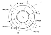
例えば、上述した実施形態では、中心角が180度の半円環形状を有するサイドプレート17,18を備えたジャーナル軸受10について説明したが、サイドプレート17,18の構成はこれに限定されるものではない。例えば、図7に示す実施形態では、サイドプレートは、中心角が180度より大きい上半部サイドプレート17A,18Aと、中心角が180度より小さい下半部サイドプレート17B,18Bと、を有する半割形状となっている。あるいは、図8に示す実施形態では、サイドプレートは、第1領域を含む下半部サイドプレート17B,18Bと、第2領域を含む上半部サイドプレート17A,18Aと、第1領域及び第2領域の何れも含まない他のサイドプレート17C,18Cと、を備える3分割形状となっている。
For example, in the above-described embodiment, the journal bearing 10 including the
例えば、「ある方向に」、「ある方向に沿って」、「平行」、「直交」、「中心」、「同心」或いは「同軸」等の相対的或いは絶対的な配置を表す表現は、厳密にそのような配置を表すのみならず、公差、若しくは、同じ機能が得られる程度の角度や距離をもって相対的に変位している状態も表すものとする。
例えば、「同一」、「等しい」及び「均質」等の物事が等しい状態であることを表す表現は、厳密に等しい状態を表すのみならず、公差、若しくは、同じ機能が得られる程度の差が存在している状態も表すものとする。
例えば、四角形状や円筒形状等の形状を表す表現は、幾何学的に厳密な意味での四角形状や円筒形状等の形状を表すのみならず、同じ効果が得られる範囲で、凹凸部や面取り部等を含む形状も表すものとする。
一方、一の構成要素を「備える」、「含む」、又は、「有する」という表現は、他の構成要素の存在を除外する排他的な表現ではない。
For example, expressions expressing relative or absolute arrangements such as “in a certain direction”, “along a certain direction”, “parallel”, “orthogonal”, “center”, “concentric” or “coaxial” are strictly In addition to such an arrangement, it is also possible to represent a state of relative displacement with an angle or a distance such that tolerance or the same function can be obtained.
For example, an expression indicating that things such as “identical”, “equal”, and “homogeneous” are in an equal state not only represents an exactly equal state, but also has a tolerance or a difference that can provide the same function. It also represents the existing state.
For example, expressions representing shapes such as quadrangular shapes and cylindrical shapes represent not only geometrically strict shapes such as quadrangular shapes and cylindrical shapes, but also irregularities and chamfers as long as the same effects can be obtained. A shape including a part or the like is also expressed.
On the other hand, the expression “comprising”, “including”, or “having” one constituent element is not an exclusive expression that excludes the presence of the other constituent elements.
1 回転機械
2 ロータ軸
10 ジャーナル軸受
12 上半部キャリアリング
13 下半部キャリアリング
17,18 サイドプレート
17A,18A 上半部サイドプレート
17B,18B 下半部サイドプレート
20,21 ガイドメタル
25,26 第1給油ユニット
27,28 給油ユニット
29 第2給油ユニット
30 第1軸受パッド
32 第2軸受パッド
34,36 キャリーオーバ抑制部
40 第1隙間
42 第2隙間
50 接合面
52 開口
1
Claims (12)
前記キャリアリングの下半領域の内周側に設けられ、ロータ軸を下方から支持するように構成された複数の軸受パッドと、
前記ロータ軸の軸方向における前記複数の軸受パッドの両側に設けられる一対のサイドプレートと、を備え、
各々の前記サイドプレートは、
前記複数の軸受パッドのうち最上流側に位置する第1軸受パッドの上流側の周方向範囲を含む第1領域と、
前記第1領域の上流側に位置し、前記サイドプレートの内周面と前記ロータ軸の外周面との間の間隔が前記第1領域よりも大きい第2領域と、
を含み、
各々の前記サイドプレートは、
前記第1領域を形成する下半部と、
前記下半部よりも内径が大きく、前記第2領域を形成する上半部と、
を含む
ことを特徴とするジャーナル軸受。 With carrier ring,
A plurality of bearing pads provided on the inner peripheral side of the lower half region of the carrier ring and configured to support the rotor shaft from below;
A pair of side plates provided on both sides of the plurality of bearing pads in the axial direction of the rotor shaft,
Each said side plate
A first region including a circumferential range on the upstream side of the first bearing pad located on the most upstream side among the plurality of bearing pads;
A second region located on the upstream side of the first region, wherein the distance between the inner peripheral surface of the side plate and the outer peripheral surface of the rotor shaft is larger than the first region;
Only including,
Each said side plate
A lower half forming the first region;
An inner diameter larger than the lower half, and forming the second region;
Journal bearing, characterized in that <br/> including.
各々の前記サイドプレートの前記上半部の内周面と前記ロータ軸の外周面との間に前記第1隙間よりも大きくて一定の第2隙間が形成されることを特徴とする請求項1乃至6の何れか一項に記載のジャーナル軸受。 A fixed first gap is formed between the inner peripheral surface of the lower half of each side plate and the outer peripheral surface of the rotor shaft,
2. A second gap that is larger than the first gap and is constant is formed between the inner circumferential surface of the upper half of each side plate and the outer circumferential surface of the rotor shaft. The journal bearing as described in any one of thru | or 6.
前記ジャーナル軸受によって支持されるロータ軸と、
を備えることを特徴とする回転機械。 The journal bearing according to any one of claims 1 to 11,
A rotor shaft supported by the journal bearing;
A rotating machine comprising:
Priority Applications (6)
| Application Number | Priority Date | Filing Date | Title |
|---|---|---|---|
| JP2016036926A JP6571026B2 (en) | 2016-02-29 | 2016-02-29 | Journal bearing and rotating machine |
| PCT/JP2017/007666 WO2017150496A1 (en) | 2016-02-29 | 2017-02-28 | Journal bearing and rotary machine |
| US16/079,411 US10451105B2 (en) | 2016-02-29 | 2017-02-28 | Journal bearing and rotary machine |
| CN201780012989.XA CN108700111B (en) | 2016-02-29 | 2017-02-28 | Journal bearing and rotary machine |
| DE112017001041.1T DE112017001041T5 (en) | 2016-02-29 | 2017-02-28 | Sliding or radial bearing and lathe |
| KR1020187024491A KR102055517B1 (en) | 2016-02-29 | 2017-02-28 | Journal bearing and rolling machine |
Applications Claiming Priority (1)
| Application Number | Priority Date | Filing Date | Title |
|---|---|---|---|
| JP2016036926A JP6571026B2 (en) | 2016-02-29 | 2016-02-29 | Journal bearing and rotating machine |
Publications (3)
| Publication Number | Publication Date |
|---|---|
| JP2017155755A JP2017155755A (en) | 2017-09-07 |
| JP2017155755A5 JP2017155755A5 (en) | 2019-02-28 |
| JP6571026B2 true JP6571026B2 (en) | 2019-09-04 |
Family
ID=59744061
Family Applications (1)
| Application Number | Title | Priority Date | Filing Date |
|---|---|---|---|
| JP2016036926A Active JP6571026B2 (en) | 2016-02-29 | 2016-02-29 | Journal bearing and rotating machine |
Country Status (6)
| Country | Link |
|---|---|
| US (1) | US10451105B2 (en) |
| JP (1) | JP6571026B2 (en) |
| KR (1) | KR102055517B1 (en) |
| CN (1) | CN108700111B (en) |
| DE (1) | DE112017001041T5 (en) |
| WO (1) | WO2017150496A1 (en) |
Families Citing this family (4)
| Publication number | Priority date | Publication date | Assignee | Title |
|---|---|---|---|---|
| JP7231437B2 (en) * | 2019-02-20 | 2023-03-01 | 三菱重工業株式会社 | Oil bath type bearing device and rotating machine |
| CN110332225B (en) * | 2019-06-28 | 2020-06-23 | 湖南行必达网联科技有限公司 | Bearing and bearing assembly |
| JP7391189B2 (en) * | 2020-04-07 | 2023-12-04 | 三菱電機株式会社 | Journal bearings and rotating equipment using journal bearings |
| WO2022157850A1 (en) * | 2021-01-20 | 2022-07-28 | 三菱電機株式会社 | Journal bearing and rotating machine |
Family Cites Families (15)
| Publication number | Priority date | Publication date | Assignee | Title |
|---|---|---|---|---|
| US3687510A (en) * | 1970-11-12 | 1972-08-29 | Westinghouse Electric Corp | Pivoted pad journal bearing |
| US4686403A (en) * | 1986-11-07 | 1987-08-11 | Westinghouse Electric Corp. | Dynamoelectric machine with rockable bearing supports |
| JP3342267B2 (en) * | 1995-10-27 | 2002-11-05 | 三菱重工業株式会社 | Pressure dam type journal bearing |
| US5738445A (en) * | 1997-02-21 | 1998-04-14 | Delaware Capital Formation, Inc. | Journal bearing having vibration damping elements |
| US6485182B2 (en) * | 2001-03-28 | 2002-11-26 | Rotating Machinery Technology, Inc. | Sleeve bearing with bypass cooling |
| JP2003176818A (en) * | 2001-12-11 | 2003-06-27 | Hitachi Ltd | Pad type journal bearing |
| JP5182756B2 (en) * | 2008-10-22 | 2013-04-17 | 株式会社不二越 | Railway vehicle bearing device |
| JP4727708B2 (en) | 2008-11-12 | 2011-07-20 | 三菱重工業株式会社 | Journal bearing |
| JP4764486B2 (en) | 2009-02-27 | 2011-09-07 | 三菱重工業株式会社 | Journal bearing |
| JP5370215B2 (en) * | 2010-03-02 | 2013-12-18 | 株式会社Ihi | Tilting pad journal bearing |
| JP2013204651A (en) * | 2012-03-28 | 2013-10-07 | Mitsubishi Heavy Ind Ltd | Journal bearing |
| JP6037916B2 (en) | 2013-03-29 | 2016-12-07 | 三菱日立パワーシステムズ株式会社 | Rotating shaft support structure and rotating machine |
| JP6101135B2 (en) * | 2013-04-03 | 2017-03-22 | 三菱重工業株式会社 | Bearing device and rotating machine |
| JP6410006B2 (en) | 2013-08-01 | 2018-10-24 | 株式会社Ihi回転機械エンジニアリング | Tilting pad bearing and turbo compressor |
| JP6249230B2 (en) | 2014-04-09 | 2017-12-20 | 三菱重工業株式会社 | Thrust bearing and rotating machine equipped with the thrust bearing |
-
2016
- 2016-02-29 JP JP2016036926A patent/JP6571026B2/en active Active
-
2017
- 2017-02-28 WO PCT/JP2017/007666 patent/WO2017150496A1/en active Application Filing
- 2017-02-28 CN CN201780012989.XA patent/CN108700111B/en active Active
- 2017-02-28 KR KR1020187024491A patent/KR102055517B1/en active IP Right Grant
- 2017-02-28 DE DE112017001041.1T patent/DE112017001041T5/en active Pending
- 2017-02-28 US US16/079,411 patent/US10451105B2/en active Active
Also Published As
| Publication number | Publication date |
|---|---|
| JP2017155755A (en) | 2017-09-07 |
| CN108700111A (en) | 2018-10-23 |
| WO2017150496A1 (en) | 2017-09-08 |
| US10451105B2 (en) | 2019-10-22 |
| KR102055517B1 (en) | 2019-12-12 |
| DE112017001041T5 (en) | 2018-12-06 |
| KR20180101594A (en) | 2018-09-12 |
| CN108700111B (en) | 2020-03-24 |
| US20190010976A1 (en) | 2019-01-10 |
Similar Documents
| Publication | Publication Date | Title |
|---|---|---|
| JP6571026B2 (en) | Journal bearing and rotating machine | |
| JP6312346B2 (en) | Journal bearing, rotating machine | |
| JP2009063015A (en) | Tilting pad type journal bearing | |
| JP2012117608A (en) | Thrust bearing device | |
| WO2017150499A1 (en) | Journal bearing and rotary machine | |
| JP2017155755A5 (en) | ||
| KR102078494B1 (en) | Journal bearing and rolling machine | |
| KR102155064B1 (en) | Journal bearing and rotating machine | |
| JP2016217364A (en) | Tilting pad type journal bearing | |
| JP2019124277A (en) | Tilting pad bearing device and rotary machine | |
| JP5812973B2 (en) | Journal bearing and steam turbine | |
| JP6403593B2 (en) | Journal bearing and rotating machine | |
| JP6437838B2 (en) | Journal bearing and rotating machine | |
| WO2021205523A1 (en) | Journal bearing and rotating machine in which journal bearing is used | |
| JP5049897B2 (en) | Rotating machine bearing device |
Legal Events
| Date | Code | Title | Description |
|---|---|---|---|
| A521 | Request for written amendment filed |
Free format text: JAPANESE INTERMEDIATE CODE: A523 Effective date: 20190116 |
|
| A621 | Written request for application examination |
Free format text: JAPANESE INTERMEDIATE CODE: A621 Effective date: 20190116 |
|
| TRDD | Decision of grant or rejection written | ||
| A01 | Written decision to grant a patent or to grant a registration (utility model) |
Free format text: JAPANESE INTERMEDIATE CODE: A01 Effective date: 20190723 |
|
| A61 | First payment of annual fees (during grant procedure) |
Free format text: JAPANESE INTERMEDIATE CODE: A61 Effective date: 20190807 |
|
| R150 | Certificate of patent or registration of utility model |
Ref document number: 6571026 Country of ref document: JP Free format text: JAPANESE INTERMEDIATE CODE: R150 |
|
| S533 | Written request for registration of change of name |
Free format text: JAPANESE INTERMEDIATE CODE: R313533 |
|
| R350 | Written notification of registration of transfer |
Free format text: JAPANESE INTERMEDIATE CODE: R350 |