JP6570216B2 - Image processing apparatus, control method thereof, and program - Google Patents
Image processing apparatus, control method thereof, and program Download PDFInfo
- Publication number
- JP6570216B2 JP6570216B2 JP2014070080A JP2014070080A JP6570216B2 JP 6570216 B2 JP6570216 B2 JP 6570216B2 JP 2014070080 A JP2014070080 A JP 2014070080A JP 2014070080 A JP2014070080 A JP 2014070080A JP 6570216 B2 JP6570216 B2 JP 6570216B2
- Authority
- JP
- Japan
- Prior art keywords
- switch
- state
- cover
- confirmation screen
- closed
- Prior art date
- Legal status (The legal status is an assumption and is not a legal conclusion. Google has not performed a legal analysis and makes no representation as to the accuracy of the status listed.)
- Expired - Fee Related
Links
Images


Classifications
-
- H—ELECTRICITY
- H04—ELECTRIC COMMUNICATION TECHNIQUE
- H04N—PICTORIAL COMMUNICATION, e.g. TELEVISION
- H04N1/00—Scanning, transmission or reproduction of documents or the like, e.g. facsimile transmission; Details thereof
- H04N1/00795—Reading arrangements
- H04N1/00798—Circuits or arrangements for the control thereof, e.g. using a programmed control device or according to a measured quantity
- H04N1/00822—Selecting or setting a particular reading mode, e.g. from amongst a plurality of modes, simplex or duplex, or high or low resolution
-
- H—ELECTRICITY
- H04—ELECTRIC COMMUNICATION TECHNIQUE
- H04N—PICTORIAL COMMUNICATION, e.g. TELEVISION
- H04N1/00—Scanning, transmission or reproduction of documents or the like, e.g. facsimile transmission; Details thereof
- H04N1/0035—User-machine interface; Control console
- H04N1/00352—Input means
- H04N1/00384—Key input means, e.g. buttons or keypads
-
- H—ELECTRICITY
- H04—ELECTRIC COMMUNICATION TECHNIQUE
- H04N—PICTORIAL COMMUNICATION, e.g. TELEVISION
- H04N1/00—Scanning, transmission or reproduction of documents or the like, e.g. facsimile transmission; Details thereof
- H04N1/00681—Detecting the presence, position or size of a sheet or correcting its position before scanning
-
- H—ELECTRICITY
- H04—ELECTRIC COMMUNICATION TECHNIQUE
- H04N—PICTORIAL COMMUNICATION, e.g. TELEVISION
- H04N1/00—Scanning, transmission or reproduction of documents or the like, e.g. facsimile transmission; Details thereof
- H04N1/32—Circuits or arrangements for control or supervision between transmitter and receiver or between image input and image output device, e.g. between a still-image camera and its memory or between a still-image camera and a printer device
- H04N1/32037—Automation of particular transmitter jobs, e.g. multi-address calling, auto-dialing
- H04N1/32058—Abbreviated dialing, e.g. one-touch dialing
Landscapes
- Engineering & Computer Science (AREA)
- Multimedia (AREA)
- Signal Processing (AREA)
- Automation & Control Theory (AREA)
- Facsimiles In General (AREA)
- Accessory Devices And Overall Control Thereof (AREA)
- Control Or Security For Electrophotography (AREA)
Description
本発明は、画像処理装置、その制御方法及びプログラムに関する。
The present invention relates to an image processing apparatus, a control method thereof, and a program.
近年、装置サイズがコンパクトな画像形成装置の分野においてコスト競争が激しいだけでなく、更なる小型化かつ高機能化が求められている。また、パーソナルコンピューター及びネットワークが広く普及し、画像形成装置と外部装置とが連携して、画像形成装置のスキャナーから画像を読み取り、ファクシミリを送信できることはもちろん電子データとして外部装置に送信する機能が提供されてきている。 In recent years, not only is cost competition intense in the field of image forming apparatuses with compact apparatus sizes, but further miniaturization and higher functionality have been demanded. In addition, personal computers and networks have become widespread, and image forming devices and external devices can cooperate to read images from scanners of image forming devices and send facsimiles, as well as to send data to external devices as electronic data. Has been.
送信に際して、送信先を簡便に指定する方法として特定のハードウェアキーに送信先を割り当てたワンタッチキーや数桁の特定番号に送信先を割り当てた短縮ダイヤルが知られている。特許文献1は、操作パネルに開閉可能なカバーを装着し、カバーの開閉状態に応じて、ワンタッチキーの役割を切り替えるように構成した画像形成装置を提案している。 As a method for easily specifying a transmission destination at the time of transmission, a one-touch key in which the transmission destination is assigned to a specific hardware key and a speed dial in which the transmission destination is assigned to a specific number of several digits are known. Patent Document 1 proposes an image forming apparatus in which a cover that can be opened and closed is attached to an operation panel, and the role of a one-touch key is switched according to the open / closed state of the cover.
このような開閉可能なカバーが設けられたハードウェアキーを有する画像形成装置において、カバー開閉センサーの異常を検出する構成を備えることで、ファクシミリ誤送信を防止するための技術が検討されている。例えば、カバーの開閉を検出する複数のセンサーを備え、センサーの出力が予め定められた組み合わせのときだけファクシミリ送信宛先のワンタッチキー操作を受け付けるように構成されたものがある。特許文献2は、ワンタッチキーが操作されたときに、カバー開閉センサーの出力が不適切な組み合わせであれば、サービスエラーを発生させて装置を使用できなくする技術を提案している。 In an image forming apparatus having a hardware key provided with such an openable / closable cover, a technique for preventing erroneous transmission of a facsimile by providing a configuration for detecting an abnormality of the cover open / close sensor has been studied. For example, there is a configuration that includes a plurality of sensors that detect opening and closing of a cover and that accepts a one-touch key operation of a facsimile transmission destination only when the outputs of the sensors are in a predetermined combination. Japanese Patent Application Laid-Open No. 2004-228688 proposes a technique for causing a service error and making the device unusable if the output of the cover open / close sensor is an inappropriate combination when a one-touch key is operated.
特許文献3は、上記カバーセンサー値の判定の他に、ワンタッチキー及び短縮ダイヤルの押し間違いによる誤送信を防止する技術を提案している。具体的には、ワンタッチキーに割り当てられた送信先を表示するための表示部を用意するといった方法が提案されている。さらには、送信前に登録内容を表示し、ユーザーの確認を促すか否かをユーザー設定で任意に切り替え可能な手法も提案されている。この手法では、ワンタッチ/短縮ダイヤルの利便性を考慮し、デフォルトでは「表示しない」に設定されている。 Patent Document 3 proposes a technique for preventing erroneous transmission due to erroneous pressing of a one-touch key and an abbreviated dial in addition to the determination of the cover sensor value. Specifically, a method has been proposed in which a display unit for displaying a transmission destination assigned to a one-touch key is prepared. Furthermore, a method has been proposed in which registration contents are displayed before transmission, and whether or not user confirmation is prompted can be arbitrarily switched by user settings. In this method, in consideration of the convenience of one-touch / abbreviated dialing, the default setting is “not display”.
しかしながら、上記従来技術には以下に記載する問題がある。例えば、上記従来技術による画像形成装置では、カバー開閉センサーからの出力が不適切であれば、すぐにサービスコールしてしまうため利便性が悪かった。ただし、単純にサービスエラーを解除してしまうと、複数のカバー開閉センサーを備えていたとしても、両センサーが故障した場合、センサー値が同じとなるため、正常時との判別がつかなくなってしまう。このとき、ワンタッチ誤入力防止のための入力宛先確認画面を「表示する」に設定にしていなかった場合には、指定した送信先が正しいものであるかをユーザーに確認させる方法がない。そのため、指定した送信先が間違っていたとしても、ユーザーはそれに気付かず送信してしまう可能性があり、ファクシミリ誤送信の懸念は払拭されない。さらには、カバーセンサー故障時を想定し、入力宛先確認画面のデフォルト設定を「表示する」としてしまうと、問題がない場合にも入力宛先確認画面が表示されるため、ユーザビリティの低下を招いてしまう。 However, the above prior art has the following problems. For example, in the image forming apparatus according to the above-described prior art, if the output from the cover opening / closing sensor is inappropriate, a service call is made immediately, which is not convenient. However, if the service error is simply canceled, even if multiple cover open / close sensors are provided, if both sensors fail, the sensor values will be the same, making it impossible to distinguish between normal and normal conditions. . At this time, if the input destination confirmation screen for preventing one-touch erroneous input is not set to “display”, there is no method for allowing the user to confirm whether the designated transmission destination is correct. For this reason, even if the designated transmission destination is wrong, there is a possibility that the user will transmit without knowing that, and the fear of erroneous facsimile transmission will not be dispelled. Furthermore, assuming that the cover sensor is out of order, if the default setting of the input destination confirmation screen is set to “display”, the input destination confirmation screen is displayed even if there is no problem, leading to a decrease in usability. .
本発明は、上述の問題に鑑みて成されたものであり、誤送信を抑制しつつ、ユーザーフレンドリーな操作体系を提供し、カバーの開閉状態に応じた異なる送信宛先が登録されるワンタッチキーに設けられた開閉カバーの状態異常を記憶し、その後にワンタッチキーが操作された場合に開閉カバーの開閉状態に応じてワンタッチキーに割り当てられた送信宛先をユーザーに確認するか否かを好適に決定する仕組みを提供することを目的とする。
The present invention has been made in view of the above-described problems, provides a user-friendly operation system while suppressing erroneous transmission, and a one-touch key in which different transmission destinations are registered according to the open / closed state of the cover. It memorizes the abnormal state of the provided open / close cover, and when the one-touch key is operated after that, decides whether or not to confirm with the user the transmission destination assigned to the one-touch key according to the open / close state of the open / close cover The purpose is to provide a mechanism to do this.
本発明は、画像処理装置であって、開閉可能なカバーと、前記開閉可能なカバーにより覆われるように配置され、前記カバーの開閉状態に応じた異なる送信宛先が登録されるワンタッチキーと、前記カバーが閉じられると押下される第1スイッチ及び第2スイッチと、前記第1スイッチ及び前記第2スイッチの状態が異なる状態であったことを示す不一致情報を記憶する不揮発性記憶手段と、前記ワンタッチキーが操作された際に、前記第1スイッチの状態及び前記第2スイッチの状態が互いに等しい状態であって、かつ、前記不揮発性記憶手段に前記不一致情報が記憶されている場合には、前記カバーの開状態または閉状態に応じた画像データを送信する送信宛先をユーザーに確認する確認画面を表示部に表示し、前記第1スイッチの状態及び前記第2スイッチの状態が互いに異なる場合には、前記不一致情報を前記不揮発性記憶手段に記憶する制御手段と、を備え、前記制御手段は、前記ワンタッチキーが操作された際に、前記第1スイッチの状態及び前記第2スイッチの状態が互いに等しい状態であって、かつ、前記不揮発性記憶手段に前記不一致情報が記憶されていない場合には、前記確認画面を表示部に表示することなく、前記カバーの開状態または閉状態に応じた前記送信宛先を設定することを特徴とする。
The present invention is an image processing apparatus, an openable / closable cover, a one-touch key arranged so as to be covered by the openable / closable cover, and registered with different transmission destinations according to the open / closed state of the cover, A first switch and a second switch which are pressed when the cover is closed; a non-volatile storage means for storing mismatch information indicating that the first switch and the second switch are in different states; and the one-touch operation If the state of the first switch and the state of the second switch are equal to each other when the key is operated, and the mismatch information is stored in the nonvolatile storage means, A confirmation screen for confirming a transmission destination for transmitting image data according to an open state or a closed state of the cover is displayed on the display unit, and the state of the first switch And the control means for storing the mismatch information in the nonvolatile storage means when the states of the second switches are different from each other, the control means when the one-touch key is operated. When the state of one switch and the state of the second switch are equal to each other and the non-matching information is not stored in the nonvolatile storage means, the confirmation screen is not displayed on the display unit. The transmission destination is set according to an open state or a closed state of the cover .
本発明によれば、誤送信を抑制しつつ、ユーザーフレンドリーな操作体系を提供し、カバーの開閉状態に応じた異なる送信宛先が登録されるワンタッチキーに設けられた開閉カバーの状態異常を記憶し、その後にワンタッチキーが操作された場合に開閉カバーの開閉状態に応じてワンタッチキーに割り当てられた送信宛先をユーザーに確認するか否かを好適に決定することができる。
According to the present invention, a user-friendly operation system is provided while suppressing erroneous transmission, and an abnormal state of the opening / closing cover provided in the one-touch key in which different transmission destinations are registered according to the opening / closing state of the cover is stored. Then, when the one-touch key is operated thereafter, it can be suitably determined whether to confirm with the user the transmission destination assigned to the one-touch key according to the open / close state of the open / close cover.
以下、添付図面を参照して本発明の実施形態を詳しく説明する。なお、以下の実施形態は特許請求の範囲に係る本発明を限定するものでなく、また本実施形態で説明されている特徴の組み合わせの全てが本発明の解決手段に必須のものとは限らない。 Hereinafter, embodiments of the present invention will be described in detail with reference to the accompanying drawings. The following embodiments do not limit the present invention according to the claims, and all combinations of features described in the present embodiments are not necessarily essential to the solution means of the present invention. .
<第1の実施形態>
<画像形成装置の構成>
以下では、図1乃至図8を参照して、本発明の第1の実施形態について説明する。まず、図1を参照して、本実施形態に係る画像形成装置の構成について説明する。図1において、各ブロックは、モジュールを示しており、ブロック間の矢印はデータ又は指示の流れを示している。
<First Embodiment>
<Configuration of image forming apparatus>
In the following, a first embodiment of the present invention will be described with reference to FIGS. First, the configuration of the image forming apparatus according to the present embodiment will be described with reference to FIG. In FIG. 1, each block indicates a module, and an arrow between the blocks indicates a flow of data or instructions.
画像形成装置100は、印刷部107、読取部109、操作パネル110、回線I/F112、及び、これらの制御を司るコントローラ部101を備える。コントローラ部101は、CPU102、RAM103、ROM104、印刷部I/F106、読取部I/F108、MODEM111、USBI/F115、及びネットワークI/F118を備える。各ブロックは、システムバス105にて接続されている。
The
CPU102は、各種制御プログラムに従って各ブロックを総括的に制御する。CPU102は、ROM104のプログラム領域に記憶された制御プログラムを読み出すことによって実行する。或いは、CPU102は、ROM104のプログラム領域に記憶された圧縮されたデータをRAM103へ伸張、展開して実行する。また、不図示のハードディスクドライブ(HDD)に前述の各種制御プログラムを圧縮状態/非圧縮状態で格納してもよい。
The
ネットワークI/F118は、ネットワーク(LAN)120などを介してホストコンピュータ121(図中、PCと表記;以降、PCと称する。)との通信処理を行う。ネットワークI/F118とネットワーク網120とは、LANケーブル119などの通信ケーブルで接続される。MODEM111は、回線I/F112を介して公衆回線網114と接続し、不図示の他の画像形成装置やファクシミリ装置、電話機などと通信処理を行う。回線I/F112と公衆回線網114とは、一般的に電話線113などで接続される。
The network I /
印刷部I/F106は、印刷部107(プリンターエンジン)に画像信号を出力するインターフェースを担う。また、読取部I/F108は、読取部109(スキャナーエンジン)からの読取画像信号を入力するインターフェースを担う。CPU102は、読取部I/F108を介して入力された画像信号を処理し、記録画像信号として印刷部I/F106へ出力する。
The printing unit I / F 106 serves as an interface for outputting an image signal to the printing unit 107 (printer engine). The reading unit I /
CPU102は、ROM104のフォント領域に記憶されたフォント情報を用いて、操作パネル110の表示部に文字や記号を表示したり、ユーザーの指示を受けた操作パネル110からの指示情報を受けたりする。また、ROM104のデータ領域には、CPU102によって画像形成装置100の装置情報や、ユーザーの電話帳情報、部門管理情報などが記憶され、CPU102により必要に応じて読み出され、必要に応じて更新される。本ブロック図では、読取部109及び印刷部107を画像形成装置100の内部にある構成としたが、それぞれもしくは両方とも外部にある構成としてもよい。
Using the font information stored in the font area of the
<操作パネル>
次に、図2を参照して、本実施形態における、画像形成装置100の操作パネル110の構成例について説明する。本実施形態における画像形成装置100は、上述の読取部109と印刷部107とによるコピー機能や、読取部109とUSBI/F115によるスキャン機能などを有するものとする。加えて、MODEM111によるファクシミリ機能や、USB(Universal Searial Bus)116やネットワーク網20経由でPC121から指示を受けた印刷(プリント)を行う機能も有する。
<Operation panel>
Next, a configuration example of the
操作パネル110について説明する。操作パネル110には、上述した機能を選択するファンクションキー201〜203があり、ユーザーは使用したい機能のボタンを操作する。また、ユーザーに設定状態や画像形成装置100の機器状態を通知するための表示部204を有する。矢印キー205は、表示部204に表示されたカーソルなどの移動に用いられる。矢印キー205は、上下左右4つのボタンがある。矢印キーの中央には、OKキー206が配置され、設定や問い合わせに対する「決定キー」の機能を有する。
The
コピー部数やファクシミリ機能における電話番号の入力などには、ユーザーはテンキー207を用いる。コピーやスキャンやファクシミリのスタートを指示するキーとして白黒スタートキー208やカラースタートキー209がある。原稿を読み取った時にカラー原稿かモノクロ原稿かを判別可能な機能を有する画像形成装置においては、図2に示すように、個別のスタートキーを設けない場合がある。
The user uses the
ストップキー210は各機能の動作を停止させる指示を行うキーである。一方、動作を停止させる方法として、ユーザーは、状態確認・停止キー211を使って現在画像形成装置100で行っている処理の状態確認画面より、停止したい処理を選択して停止させることができる。その場合も、選択や決定には、上述の矢印キー205とOKキー206とを用いる。
A
ファクシミリや送信を行う際の送信宛先の短縮入力を実現する方法としてワンタッチキー212、短縮キー213及びアドレス帳キー214がある。ワンタッチキー212は、各ボタンに対して1つの宛先が登録されており、所望のボタンを操作することで宛先を指定することができる。ワンタッチキー212の詳細な構成については図3を用いて後述する。短縮ダイヤルは短縮キー213を操作することで番号入力を促す画面が操作パネル110に表示され、所望の宛先に割り当てられた番号をテンキー207から入力することで宛先を指定することができる。アドレス帳は、画像形成装置100に登録されている宛先の一覧を表示し、矢印キー205によって宛先を選択し、OKキー206によって所望の宛先を決定する。
There are a one-
<ワンタッチキー>
次に、図3を参照して、操作パネル110を構成するワンタッチキーの構成について説明する。ワンタッチキー212には、各キーを覆うようカバー310が開閉可能に設けられている。301は、ワンタッチキー212のカバー310を閉じた状態を示す。301に示すように、ワンタッチキー212として14個の入力キーが配置されている。
<One touch key>
Next, with reference to FIG. 3, the configuration of the one-touch key constituting the
302は、ワンタッチキー212のカバー310を開けた状態を示す。カバー310は、ワンタッチキー212の図3において上側の辺を軸として開閉する仕組みである。320はワンタッチキー群の内の1つの入力キーであり、カバー10を閉じた状態ではワンタッチダイヤル番号「01」として、カバー10を開けた状態では、ワンタッチダイヤル番号「11」として、それぞれに宛先を登録できるようになっている。
315はワンタッチキー群を覆う外装である。311、312は、カバー310の内側に設けられた突起であり、313、314は外装315に設けられた開口部である。突起312はカバー310が閉じられたとき、開口部313を通じてカバー開閉検知スイッチ305を押すように構成されている。同様に、突起311はカバー310が閉じられたとき、開口部314を通じてカバー開閉検知スイッチ306を押すように構成されている。
303は、ワンタッチキー212周辺を横から見た断面図を示す。316は、カバー開閉検知スイッチ305やスイッチ306を実装する操作部基板である。303に示すように、カバー開閉検知スイッチ305やスイッチ306の真上に開口部313、314が配置されている。カバー開閉検知スイッチ305とスイッチ306は、検知結果として、カバー310が閉じて突起311、312が押されたとき電気的ON状態を出力する。また、カバー開閉検知スイッチ305とスイッチ306は、検知結果として、カバー310が開いて突起311、312が押されていないとき電気的OFF状態を、操作パネル110を介してCPU102に伝える。
<アドレス帳>
次に、図4を参照して、本実施形態における、ワンタッチキー/短縮ダイヤルとアドレス帳について説明する。図4ではワンタッチキー212においてキー01にユーザー1、キー02にユーザー2が割り当てられている。また、短縮ダイヤルとして001にユーザー3が割り当てられ,002にユーザー4が割り当てられている。短縮ダイヤルを指定するためには、短縮キー213を操作した後、テンキー207から登録されている番号を入力する。ワンタッチキー及び短縮ダイヤルに登録されている宛先は、アドレス帳からも参照/使用することができる。
<Address book>
Next, the one-touch key / abbreviated dial and the address book in this embodiment will be described with reference to FIG. In FIG. 4, user 1 is assigned to key 01 and user 2 is assigned to key 02 in one-
アドレス帳は、アドレス帳キー214を操作することで表示される。登録されている宛先がどのプロトコルのものであるかはアイコン401で示される。図4ではユーザー1〜ユーザー3は、プロトコルがファクシミリであることを示し、ユーザー4はE−Mailであることを示している。登録されている宛先がワンタッチキー212に割り当てられているか否かはアイコン402で示される。図4ではユーザー1及びユーザー2がワンタッチキー212に割り当てられている。アドレス帳に表示される項目は、タブ403によって切り替えることができる。図4では「全て」、「ワンタッチキー」、「“あ”で始まる宛先」のタブが表示されている。宛先及びタブについて、現在選択されている項目は反転表示される。図4では、「全て」が選択されている。
The address book is displayed by operating the
<故障判定>
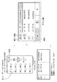
次に、図5を参照して、本実施形態における、カバーセンサーの故障判定について説明する。502、503に示すように、カバー開閉検知スイッチ305とスイッチ306とが互いに異なる出力をしているときに、CPU102は、カバー310が故障したと判定する。例えば、カバー開閉検知スイッチ305が壊れて常にON状態となってしまうならば、カバー310を開いた状態でワンタッチキーを操作したとき2つのスイッチに不整合が起きて故障と判定される。両方のスイッチがOFF状態であれば、カバー310が開状態(OPEN)であると判定される。両方のスイッチがON状態であれば、カバー310が閉状態(CLOSE)であると判定される。2つスイッチの出力が異なる場合は、不一致情報として不揮発性のメモリに記憶する。なお、詳細については後述するが、当該不一致情報を発生回数として記憶してもよい。
<Failure judgment>
Next, the failure determination of the cover sensor in the present embodiment will be described with reference to FIG. As indicated by 502 and 503, when the cover open /
なお、本実施形態に係る画像形成装置100は、図5に示す故障判定表を定義したテーブルをROM104等に予め記憶している。したがって、CPU102は、ROM104に記憶されたテーブルを参照して、故障判定を行う。なお、ここでは、2つのセンサー値が異なるか否かで故障か否か判定できるため、上記テーブルを参照することなく故障判定を行ってもよい。より複雑な判定が必要であれば、上述したテーブル等を用いて、故障判定を行うことが望ましい。以下で記載するカバーセンサーとの用語は、カバー開閉検知スイッチ305及びスイッチ306を示す。
Note that the
<画面例>
次に、図6を参照して、本実施形態におけるワンタッチキー又は短縮ダイヤルで宛先を指定した場合の画面フローについて説明する。以下で説明する画面は、操作パネル110の表示部204に表示される。601は、操作パネル110にに表示されるファクシミリ基本画面であり、宛先の入力待ちを行う画面である。この画面においてユーザーがワンタッチキー又は短縮ダイヤルから宛先を指定した場合、入力したワンタッチキー212の内容を示す入力宛先確認画面602が操作パネル110に表示され、ユーザーに対して内容の確認を促す。即ち、入力宛先確認画面602は、短縮キー等を操作したことによって設定された宛先で送信を実行するか否かをユーザーが選択可能に表示される。入力宛先確認画面602では、ワンタッチキー212の「01」が選択され、当該ワンタッチキー212に関連付けられた宛先である「0312345678」が表示されている。
<Screen example>
Next, with reference to FIG. 6, a screen flow when a destination is designated with a one-touch key or an abbreviated dial in this embodiment will be described. A screen described below is displayed on the
ユーザーは入力宛先確認画面602の内容を確認し、所望の宛先であれば、「OK」を選択し、所望の宛先でなければ「Cancel」を選択する。入力宛先確認画面602において「OK」が選択された場合、宛先が指定されたファクシミリ画面603に遷移する。入力宛先確認画面602において「Cancel」が選択された場合、宛先の指定は行われず、画面601に戻る。画面603では、送信開始を行うためのスタートキーと、送信設定とが表示される。
The user confirms the contents of the input
次に、図7を参照して、本実施形態における入力宛先確認画面602の表示可否をユーザー操作に応じて設定する画面701について説明する。画面701においてOFFが選択された場合、ワンタッチキー又は短縮ダイヤルからの宛先入力があっても、入力宛先確認画面602を表示しない。一方、画面700においてONが選択された場合、ワンタッチキー又は短縮ダイヤルからの宛先入力であれば入力宛先確認画面602を操作パネル110に表示する。
Next, a
<処理手順>
次に、図8を参照して、本実施形態における入力宛先確認画面602の表示設定切替処理の手順について説明する。以下で説明する処理は、CPU102がROM104等に格納された制御プログラムをRAM103に読み出して実行することにより実現される。
<Processing procedure>
Next, with reference to FIG. 8, the procedure of the display setting switching process of the input
S801において、CPU102は、操作パネル110を介してユーザーによって選択されたキー入力を受け付ける。続いて、S802において、CPU102は、S801で入力されたキーの種別を判定する。ワンタッチキー212以外の入力を検知した場合は、S804へと進み、CPU102は、入力キーに該当する画面を、操作パネル110の表示部204に表示し、処理を終了する。即ち、ワンタッチキー212以外の入力であれば、通常の処理が実行される。
In step S <b> 801, the
一方、ワンタッチキー212の操作による宛先入力を検知した場合は、S806へと進み、CPU102は、カバー開閉検知の機構が故障しているか否かを判定する。ここでの故障判定は、不揮発性メモリに記憶された不一致情報を参照することにより行ってもよい。具体的には、不一致情報がカバー開閉検知スイッチ305とスイッチ306とが互いに異なる出力をしていることを示す場合に、故障と判定する。この時、CPU102は、故障と判定した場合の回数を、不揮発性メモリ等に格納する。格納された情報は、センサーが不安定な状態にあるか否かを判別するために後述するS817で参照される。
On the other hand, when the destination input by the operation of the one-
もし故障していたならばS807に進み、CPU102は、誤ダイヤルになる可能性があるので、サービスコールエラーを表示部204に表示して、画像形成装置100が使用できないように制御する。カバー開閉状態の遷移タイミング、異物混入等によるセンサー値の不一致発生を考慮し、エラー状態はラッチ(保持)せず、S808の電源OFF/ON(再起動すること)によりサービスコール状態から復帰させる。エラー状態をラッチ(保持)しないとは、不揮発性のメモリに格納されない情報であることを意味し、電源OFF/ONでクリアされる。つまり、一度電源OFF/ONを行うと、過去のシステム異常状態(サービスコール状態)は検知できない。つまり、再起動することによりエラー状態を解消している。
If there is a failure, the process advances to step S807, and the
一方、故障していなければS809に進み、CPU102は、ワンタッチキー212にワンタッチダイヤル先が登録済であるか否かを判定する。なお、このフローへ進むケースとして、センサーが正常の場合だけでなく、両センサー故障の場合も含まれる。両センサーが故障した場合には、センサー値は同じとなる可能性もあるため、正常時と判別がつかない。この場合、ワンタッチダイヤル先が正しく設定されている保証はない。
On the other hand, if there is no failure, the process advances to step S809, and the
ワンタッチダイヤル先が登録されていなければS810に進み、CPU102は、ワンタッチダイヤルの登録処理を行う。ワンタッチダイヤル先が登録されていれば、S811へと進み、CPU102は、入力宛先確認画面602の表示設定を確認する。当該表示設定は、図7を用いて説明した設定情報である。入力宛先確認画面602が「表示する」に設定されていた場合は、S812においてCPU102は表示部204に入力宛先確認画面602を表示する。
If the one-touch dial destination is not registered, the process advances to step S810, and the
次に、S813において、CPU102は、ユーザーが入力宛先確認画面602において「OK」を選択したか、「Cancel」を選択したかを判定する。ユーザーが「Cancel」を選択した場合、S814に進み、CPU102は、入力された宛先を破棄して処理を終了する。
In step S813, the
一方、ユーザーが「OK」を選択した場合は、S815に進み、CPU102は、入力された宛先を送信先として設定する。これにより、送信処理が可能となる。S816において、CPU102は、設定された宛先への送信処理を実行する。
On the other hand, if the user selects “OK”, the process advances to step S815, and the
S811で入力宛先確認画面602を「表示しない」に設定されていると判定すると、S817において、CPU102は、S806で算出されるカバーセンサー故障判定回数を参照し、センサー不一致状態を判定する。センサー不一致状態は、センサー不一致状態が一度も検知されていなければ、正常な状態であると判断し、S815へと進む。S815において、CPU102は、入力された宛先を送信先として設定し、送信可能状態となる。
If it is determined in step S811 that the input
一方、ファクシミリ誤送信のリスクを少しでも軽減させるために、カバーセンサーの状態が一度でも不安定な状態になった場合は、S818へと進み、CPU102は、入力宛先確認画面602の表示設定を「表示しない」から「表示する」に切り替える。設定変更後、S812へ進み、以降同様の処理を行うことで、ユーザーは宛先設定前に入力確認を行うことが可能となる。
On the other hand, in order to reduce the risk of erroneous facsimile transmission as much as possible, if the state of the cover sensor becomes unstable even once, the process proceeds to S818, and the
以上説明したように、本実施形態によれば、ワンタッチキー操作時に、センサー不一致を検知してサービスエラー状態となっても、電源OFF/ONでサービスエラーを解除可能なため、装置を継続して使用することができる。また、カバーセンサー不一致を検知した際に、誤送信のリスクを考慮して、自動的に宛先入力確認画面を表示するよう設定が切り替わるため、サービスエラーが解除されたとしても、誤送信を防止できる可能性が高まる。つまり、最低限のセキュリティを確保しつつ、できる限りデバイスを使えるようにすることが可能になる。入力宛先確認画面602の設定変更は、サービスエラー状態とは異なり、電源OFF/ON後も保持されるため、最低限のセキュリティを確保しつつ、できる限りデバイスを使うことが可能な画像形成装置を提供できる。なお、上記実施形態では、センサー値の不一致発生回数の閾値を1としていたが、構成に応じて、所定の閾値へ変更してもよい。その場合には、当該発生回数が、変更した所定の閾値へ達した場合に強制的に確認画面を表示することがきでる。
As described above, according to the present embodiment, even when a sensor mismatch is detected and a service error state occurs when a one-touch key is operated, the service error can be canceled by turning the power OFF / ON, so the device can be continued. Can be used. Also, when the cover sensor mismatch is detected, the setting is switched to automatically display the destination input confirmation screen in consideration of the risk of erroneous transmission, so even if the service error is canceled, erroneous transmission can be prevented. The possibility increases. In other words, the device can be used as much as possible while ensuring the minimum security. The setting change of the input
<その他の実施形態>
また、本発明は、以下の処理を実行することによっても実現される。即ち、上述した実施形態の機能を実現するソフトウェア(プログラム)を、ネットワーク又は各種記憶媒体を介してシステム或いは装置に供給し、そのシステム或いは装置のコンピュータ(又はCPUやMPU等)がプログラムを読み出して実行する処理である。
<Other embodiments>
The present invention can also be realized by executing the following processing. That is, software (program) that realizes the functions of the above-described embodiments is supplied to a system or apparatus via a network or various storage media, and a computer (or CPU, MPU, etc.) of the system or apparatus reads the program. It is a process to be executed.
305:カバー開閉検知スイッチ、306:カバー開閉検知スイッチ、310:カバー、311:突起、312:突起、313:開口部、314:開口部、315:外装、316:操作部基板、100:画像形成装置 305: Cover open / close detection switch, 306: Cover open / close detection switch, 310: Cover, 311: Projection, 312: Projection, 313: Opening, 314: Opening, 315: Exterior, 316: Operation part substrate, 100: Image formation apparatus
Claims (9)
開閉可能なカバーと、
前記開閉可能なカバーにより覆われるように配置され、前記カバーの開閉状態に応じた異なる送信宛先が登録されるワンタッチキーと、
前記カバーが閉じられると押下される第1スイッチ及び第2スイッチと、
前記第1スイッチ及び前記第2スイッチの状態が異なる状態であったことを示す不一致情報を記憶する不揮発性記憶手段と、
前記ワンタッチキーが操作された際に、前記第1スイッチの状態及び前記第2スイッチの状態が互いに等しい状態であって、かつ、前記不揮発性記憶手段に前記不一致情報が記憶されている場合には、前記カバーの開状態または閉状態に応じた画像データを送信する送信宛先をユーザーに確認する確認画面を表示部に表示し、前記第1スイッチの状態及び前記第2スイッチの状態が互いに異なる場合には、前記不一致情報を前記不揮発性記憶手段に記憶する制御手段と、を備え、
前記制御手段は、前記ワンタッチキーが操作された際に、前記第1スイッチの状態及び前記第2スイッチの状態が互いに等しい状態であって、かつ、前記不揮発性記憶手段に前記不一致情報が記憶されていない場合には、前記確認画面を表示部に表示することなく、前記カバーの開状態または閉状態に応じた前記送信宛先を設定することを特徴とする画像処理装置。 An image processing apparatus,
A cover that can be opened and closed;
A one-touch key that is arranged so as to be covered by the cover that can be opened and closed, and in which different transmission destinations are registered according to the open / closed state of the cover;
A first switch and a second switch that are pressed when the cover is closed;
Nonvolatile storage means for storing inconsistency information indicating that the first switch and the second switch are in different states;
When the state of the first switch and the state of the second switch are equal to each other when the one-touch key is operated, and the inconsistency information is stored in the nonvolatile storage means When a confirmation screen for confirming a transmission destination for transmitting image data according to an open state or a closed state of the cover is displayed on the display unit, and the state of the first switch and the state of the second switch are different from each other Comprises a control means for storing the mismatch information in the nonvolatile storage means,
The control means is configured such that when the one-touch key is operated, the state of the first switch and the state of the second switch are equal to each other, and the mismatch information is stored in the nonvolatile storage means. If not, the transmission destination is set according to the open state or the closed state of the cover without displaying the confirmation screen on the display unit.
ユーザー操作に従って、前記確認画面を前記表示部に表示するべきか否かの確認設定を行い、
前記ワンタッチキーの操作に従って前記送信宛先を設定する際に、前記確認設定に基づいて前記表示部に前記確認画面を表示させることを特徴とする請求項1に記載の画像処理装置。 The control means includes
According to the user operation, confirm setting whether to display the confirmation screen on the display unit,
The image processing apparatus according to claim 1, wherein when setting the transmission destination in accordance with an operation of one-touch keys, and wherein the displaying the confirmation screen on the display unit based on the verification settings.
前記第1スイッチの状態及び前記第2スイッチの状態が互いに等しい状態であって、かつ、前記不揮発性記憶手段に前記不一致情報が記憶されている場合には、前記確認設定が前記確認画面を表示しないように設定されている場合であっても、前記確認画面を表示部に表示させることを特徴とする請求項2に記載の画像処理装置。 The control means includes
When the state of the first switch and the state of the second switch are equal to each other and the mismatch information is stored in the nonvolatile storage means, the confirmation setting displays the confirmation screen. The image processing apparatus according to claim 2 , wherein the confirmation screen is displayed on a display unit even when the setting is made so as not to perform.
前記第1スイッチの状態及び前記第2スイッチの状態が互いに異なった発生回数を前記不一致情報として前記不揮発性記憶手段に記憶させ、該発生回数が所定の閾値に達した場合には、前記確認設定が前記確認画面を表示しないように設定されている場合であっても、前記確認画面を前記表示部に表示させることを特徴とする請求項2に記載の画像処理装置。 The control means includes
The number of occurrences in which the state of the first switch and the state of the second switch are different from each other is stored in the nonvolatile storage means as the discrepancy information, and when the number of occurrences reaches a predetermined threshold, the confirmation setting The image processing apparatus according to claim 2 , wherein the confirmation screen is displayed on the display unit even when the confirmation screen is set not to be displayed.
前記カバーが閉じられたときに、該カバーに設けられた突起によって押されるスイッチであることを特徴とする請求項1乃至5の何れか1項に記載の画像処理装置。 The first switch and the second switch are:
When the cover is closed, the image processing apparatus according to any one of claims 1 to 5, characterized in that a switch which is pressed by a projection provided on the cover.
制御手段が、前記ワンタッチキーが操作された際に、前記第1スイッチの状態及び前記第2スイッチの状態が互いに等しい状態であって、かつ、前記不揮発性記憶手段に前記不一致情報が記憶されている場合には、前記カバーの開状態または閉状態に応じた画像データを送信する送信宛先をユーザーに確認する確認画面を表示部に表示し、前記第1スイッチの状態及び前記第2スイッチの状態が互いに異なる場合には、前記不一致情報を前記不揮発性記憶手段に記憶する制御工程を、含み、
前記制御工程は、前記ワンタッチキーが操作された際に、前記第1スイッチの状態及び前記第2スイッチの状態が互いに等しい状態であって、かつ、前記不揮発性記憶手段に前記不一致情報が記憶されていない場合には、前記確認画面を表示部に表示することなく、前記カバーの開状態または閉状態に応じた前記送信宛先を設定することを特徴とする画像処理装置の制御方法。 A cover that can be opened and closed, a one-touch key that is arranged so as to be covered by the cover that can be opened and closed, and that stores different transmission destinations according to the opened and closed state of the cover, and a first switch that is pressed when the cover is closed And a non-volatile storage means for storing mismatch information indicating that the states of the first switch and the second switch are different from each other, and a control method of the image processing apparatus,
When the one-touch key is operated by the control means, the state of the first switch and the state of the second switch are equal to each other, and the inconsistency information is stored in the nonvolatile storage means. A confirmation screen for confirming a transmission destination for transmitting image data according to the open state or the closed state of the cover is displayed on the display unit, and the state of the first switch and the state of the second switch Are different from each other, includes a control step of storing the mismatch information in the nonvolatile storage means,
In the control step, when the one-touch key is operated, the state of the first switch and the state of the second switch are equal to each other, and the inconsistency information is stored in the nonvolatile storage means. If not, the transmission destination according to the open state or the closed state of the cover is set without displaying the confirmation screen on a display unit.
Priority Applications (2)
| Application Number | Priority Date | Filing Date | Title |
|---|---|---|---|
| JP2014070080A JP6570216B2 (en) | 2014-03-28 | 2014-03-28 | Image processing apparatus, control method thereof, and program |
| US14/662,483 US9560230B2 (en) | 2014-03-28 | 2015-03-19 | Image forming apparatus, control method for the same and storage medium |
Applications Claiming Priority (1)
| Application Number | Priority Date | Filing Date | Title |
|---|---|---|---|
| JP2014070080A JP6570216B2 (en) | 2014-03-28 | 2014-03-28 | Image processing apparatus, control method thereof, and program |
Publications (3)
| Publication Number | Publication Date |
|---|---|
| JP2015192410A JP2015192410A (en) | 2015-11-02 |
| JP2015192410A5 JP2015192410A5 (en) | 2017-05-18 |
| JP6570216B2 true JP6570216B2 (en) | 2019-09-04 |
Family
ID=54192137
Family Applications (1)
| Application Number | Title | Priority Date | Filing Date |
|---|---|---|---|
| JP2014070080A Expired - Fee Related JP6570216B2 (en) | 2014-03-28 | 2014-03-28 | Image processing apparatus, control method thereof, and program |
Country Status (2)
| Country | Link |
|---|---|
| US (1) | US9560230B2 (en) |
| JP (1) | JP6570216B2 (en) |
Families Citing this family (3)
| Publication number | Priority date | Publication date | Assignee | Title |
|---|---|---|---|---|
| JP6086114B2 (en) * | 2014-12-29 | 2017-03-01 | コニカミノルタ株式会社 | Information transmitting apparatus, information transmitting method, and information transmitting program |
| JP6633909B2 (en) | 2015-12-24 | 2020-01-22 | 株式会社東芝 | Image processing device |
| JP6745671B2 (en) | 2016-08-01 | 2020-08-26 | キヤノン株式会社 | Printing device, control method thereof, and program |
Family Cites Families (29)
| Publication number | Priority date | Publication date | Assignee | Title |
|---|---|---|---|---|
| DE3545081A1 (en) * | 1984-12-25 | 1986-07-03 | Kabushiki Kaisha Toshiba, Kawasaki, Kanagawa | IMAGE GENERATING DEVICE WITH DOCUMENT SIZE DETECTION |
| US5250262A (en) * | 1989-11-22 | 1993-10-05 | Vettest S.A. | Chemical analyzer |
| JPH06303301A (en) | 1993-04-15 | 1994-10-28 | Murata Mach Ltd | Communication terminal equipment |
| KR100336056B1 (en) * | 1993-09-21 | 2002-12-12 | 산요 덴키 가부시키가이샤 | Compound recording device |
| JP2919724B2 (en) * | 1993-11-04 | 1999-07-19 | 三洋電機株式会社 | Composite recording device |
| JP3539781B2 (en) * | 1995-02-14 | 2004-07-07 | 東芝テック株式会社 | Composite image forming device |
| US6542633B1 (en) * | 1997-10-31 | 2003-04-01 | Canon Kabushiki Kaisha | Image forming system with capability for color correction |
| JP3346367B2 (en) * | 2000-02-22 | 2002-11-18 | 村田機械株式会社 | Operation input device |
| JP3485058B2 (en) | 2000-02-23 | 2004-01-13 | 村田機械株式会社 | control panel |
| JP2002100256A (en) * | 2000-06-22 | 2002-04-05 | Tokyo Seimitsu Co Ltd | Non-forced opening switch device and switch device for detecting opening and closing cassette cover |
| JP2003315939A (en) * | 2002-04-22 | 2003-11-06 | Sharp Corp | Original cover opening/closing mechanism for original reader |
| JP2004187032A (en) * | 2002-12-04 | 2004-07-02 | Murata Mach Ltd | Original reader |
| CN101945198B (en) * | 2004-09-21 | 2012-05-30 | 兄弟工业株式会社 | Image processing apparatus |
| JP4487928B2 (en) * | 2005-12-29 | 2010-06-23 | ブラザー工業株式会社 | Communication terminal device and facsimile communication method |
| US8237995B2 (en) * | 2006-02-22 | 2012-08-07 | Oki Data Corporation | Multifunction apparatus |
| JP2008048208A (en) | 2006-08-17 | 2008-02-28 | Konica Minolta Business Technologies Inc | Image processor, and image processing method |
| JP5387464B2 (en) * | 2010-03-16 | 2014-01-15 | 株式会社リコー | Image reading apparatus and image forming apparatus |
| US8659803B2 (en) * | 2010-06-28 | 2014-02-25 | Lexmark International, Inc. | Image forming device with an adjustable scan unit |
| JP5436406B2 (en) * | 2010-12-27 | 2014-03-05 | シャープ株式会社 | Image forming apparatus, program, and recording medium |
| JP2013103477A (en) * | 2011-11-16 | 2013-05-30 | Canon Inc | Image forming apparatus, print control method, and program |
| JP5995431B2 (en) * | 2011-12-02 | 2016-09-21 | キヤノン株式会社 | Image forming apparatus, control method thereof, and program |
| JP5627561B2 (en) * | 2011-12-08 | 2014-11-19 | シャープ株式会社 | Image reading apparatus, image forming apparatus, reading method, computer program, and recording medium |
| JP5759419B2 (en) * | 2012-06-07 | 2015-08-05 | キヤノン株式会社 | Image processing apparatus, control method thereof, and program |
| JP5987611B2 (en) * | 2012-09-28 | 2016-09-07 | ブラザー工業株式会社 | Image reading apparatus and medium conveying apparatus |
| JP5983308B2 (en) * | 2012-10-25 | 2016-08-31 | ブラザー工業株式会社 | Image reading device |
| JP2014113781A (en) * | 2012-12-11 | 2014-06-26 | Canon Inc | Image forming apparatus, control method, and program |
| JP6065268B2 (en) * | 2013-01-08 | 2017-01-25 | 株式会社リコー | Document reading apparatus and image forming apparatus |
| JP2014233871A (en) * | 2013-05-31 | 2014-12-15 | キヤノン株式会社 | Image forming apparatus, control method for the apparatus, and program |
| JP6355437B2 (en) * | 2014-06-04 | 2018-07-11 | キヤノン株式会社 | Image processing apparatus, control method therefor, and program |
-
2014
- 2014-03-28 JP JP2014070080A patent/JP6570216B2/en not_active Expired - Fee Related
-
2015
- 2015-03-19 US US14/662,483 patent/US9560230B2/en active Active
Also Published As
| Publication number | Publication date |
|---|---|
| US20150281495A1 (en) | 2015-10-01 |
| US9560230B2 (en) | 2017-01-31 |
| JP2015192410A (en) | 2015-11-02 |
Similar Documents
| Publication | Publication Date | Title |
|---|---|---|
| US9160870B2 (en) | Image processing apparatus for transmitting data to a selected transmission destination, control method therefor and storage medium | |
| JP2006324968A (en) | Method, program, and device for data transmission | |
| US9609148B2 (en) | Communication apparatus, method of controlling the same, and storage medium | |
| JP6570216B2 (en) | Image processing apparatus, control method thereof, and program | |
| JP6055853B2 (en) | Display input device and image forming apparatus having the same | |
| JP4702399B2 (en) | COMMUNICATION DEVICE AND COMMUNICATION DEVICE CONTROL PROGRAM | |
| JP5754418B2 (en) | Image forming apparatus and program | |
| JP7172285B2 (en) | Image forming device and program | |
| JP6097535B2 (en) | Image forming apparatus, control method therefor, and program | |
| US9060066B2 (en) | Data communication apparatus, method of controlling the same, and storage medium | |
| JP6322265B2 (en) | Data transmitting apparatus, control method thereof, and program | |
| JP6055515B2 (en) | Image processing apparatus, control method thereof, and program | |
| JP2009258895A (en) | Information processing device and program | |
| JP5097647B2 (en) | Electronics | |
| JP2008283518A (en) | Communication equipment, and control method thereof | |
| JP2015089017A (en) | Facsimile device | |
| JP2007036478A (en) | Method, program, and device for transmitting data, and image processor | |
| US11700340B2 (en) | Method for registering a terminal in an image forming apparatus | |
| JP4356591B2 (en) | Electronics | |
| JP4826401B2 (en) | Image transmitting apparatus and program | |
| JP5135155B2 (en) | Electronics | |
| JP2019028508A (en) | Information processing apparatus and program | |
| JP2007088531A (en) | Communication terminal unit and electronic equipment | |
| JP2007036477A (en) | Method, program, and device for registering destination, and image processor | |
| JP2014075738A (en) | Electronic apparatus and control method of the same, and program |
Legal Events
| Date | Code | Title | Description |
|---|---|---|---|
| A521 | Request for written amendment filed |
Free format text: JAPANESE INTERMEDIATE CODE: A523 Effective date: 20170327 |
|
| A621 | Written request for application examination |
Free format text: JAPANESE INTERMEDIATE CODE: A621 Effective date: 20170327 |
|
| A977 | Report on retrieval |
Free format text: JAPANESE INTERMEDIATE CODE: A971007 Effective date: 20171017 |
|
| A131 | Notification of reasons for refusal |
Free format text: JAPANESE INTERMEDIATE CODE: A131 Effective date: 20171201 |
|
| A521 | Request for written amendment filed |
Free format text: JAPANESE INTERMEDIATE CODE: A523 Effective date: 20180125 |
|
| A131 | Notification of reasons for refusal |
Free format text: JAPANESE INTERMEDIATE CODE: A131 Effective date: 20180702 |
|
| A521 | Request for written amendment filed |
Free format text: JAPANESE INTERMEDIATE CODE: A523 Effective date: 20180829 |
|
| A02 | Decision of refusal |
Free format text: JAPANESE INTERMEDIATE CODE: A02 Effective date: 20190201 |
|
| A521 | Request for written amendment filed |
Free format text: JAPANESE INTERMEDIATE CODE: A523 Effective date: 20190423 |
|
| A911 | Transfer to examiner for re-examination before appeal (zenchi) |
Free format text: JAPANESE INTERMEDIATE CODE: A911 Effective date: 20190509 |
|
| TRDD | Decision of grant or rejection written | ||
| A01 | Written decision to grant a patent or to grant a registration (utility model) |
Free format text: JAPANESE INTERMEDIATE CODE: A01 Effective date: 20190708 |
|
| A61 | First payment of annual fees (during grant procedure) |
Free format text: JAPANESE INTERMEDIATE CODE: A61 Effective date: 20190806 |
|
| R151 | Written notification of patent or utility model registration |
Ref document number: 6570216 Country of ref document: JP Free format text: JAPANESE INTERMEDIATE CODE: R151 |
|
| LAPS | Cancellation because of no payment of annual fees |