JP6568077B2 - Coordinate system alignment of externally irradiated radiotherapy and magnetic resonance imaging systems - Google Patents
Coordinate system alignment of externally irradiated radiotherapy and magnetic resonance imaging systems Download PDFInfo
- Publication number
- JP6568077B2 JP6568077B2 JP2016544746A JP2016544746A JP6568077B2 JP 6568077 B2 JP6568077 B2 JP 6568077B2 JP 2016544746 A JP2016544746 A JP 2016544746A JP 2016544746 A JP2016544746 A JP 2016544746A JP 6568077 B2 JP6568077 B2 JP 6568077B2
- Authority
- JP
- Japan
- Prior art keywords
- radiation
- magnetic resonance
- radiation beam
- image
- processor
- Prior art date
- Legal status (The legal status is an assumption and is not a legal conclusion. Google has not performed a legal analysis and makes no representation as to the accuracy of the status listed.)
- Active
Links
Images


Classifications
-
- A—HUMAN NECESSITIES
- A61—MEDICAL OR VETERINARY SCIENCE; HYGIENE
- A61N—ELECTROTHERAPY; MAGNETOTHERAPY; RADIATION THERAPY; ULTRASOUND THERAPY
- A61N5/00—Radiation therapy
- A61N5/10—X-ray therapy; Gamma-ray therapy; Particle-irradiation therapy
- A61N5/1048—Monitoring, verifying, controlling systems and methods
- A61N5/1049—Monitoring, verifying, controlling systems and methods for verifying the position of the patient with respect to the radiation beam
-
- A—HUMAN NECESSITIES
- A61—MEDICAL OR VETERINARY SCIENCE; HYGIENE
- A61B—DIAGNOSIS; SURGERY; IDENTIFICATION
- A61B5/00—Measuring for diagnostic purposes; Identification of persons
- A61B5/0033—Features or image-related aspects of imaging apparatus classified in A61B5/00, e.g. for MRI, optical tomography or impedance tomography apparatus; arrangements of imaging apparatus in a room
- A61B5/0035—Features or image-related aspects of imaging apparatus classified in A61B5/00, e.g. for MRI, optical tomography or impedance tomography apparatus; arrangements of imaging apparatus in a room adapted for acquisition of images from more than one imaging mode, e.g. combining MRI and optical tomography
-
- A—HUMAN NECESSITIES
- A61—MEDICAL OR VETERINARY SCIENCE; HYGIENE
- A61B—DIAGNOSIS; SURGERY; IDENTIFICATION
- A61B5/00—Measuring for diagnostic purposes; Identification of persons
- A61B5/05—Detecting, measuring or recording for diagnosis by means of electric currents or magnetic fields; Measuring using microwaves or radio waves
- A61B5/055—Detecting, measuring or recording for diagnosis by means of electric currents or magnetic fields; Measuring using microwaves or radio waves involving electronic [EMR] or nuclear [NMR] magnetic resonance, e.g. magnetic resonance imaging
-
- A—HUMAN NECESSITIES
- A61—MEDICAL OR VETERINARY SCIENCE; HYGIENE
- A61N—ELECTROTHERAPY; MAGNETOTHERAPY; RADIATION THERAPY; ULTRASOUND THERAPY
- A61N5/00—Radiation therapy
- A61N5/10—X-ray therapy; Gamma-ray therapy; Particle-irradiation therapy
- A61N5/103—Treatment planning systems
- A61N5/1039—Treatment planning systems using functional images, e.g. PET or MRI
-
- A—HUMAN NECESSITIES
- A61—MEDICAL OR VETERINARY SCIENCE; HYGIENE
- A61N—ELECTROTHERAPY; MAGNETOTHERAPY; RADIATION THERAPY; ULTRASOUND THERAPY
- A61N5/00—Radiation therapy
- A61N5/10—X-ray therapy; Gamma-ray therapy; Particle-irradiation therapy
- A61N5/1048—Monitoring, verifying, controlling systems and methods
- A61N5/1064—Monitoring, verifying, controlling systems and methods for adjusting radiation treatment in response to monitoring
- A61N5/1065—Beam adjustment
- A61N5/1067—Beam adjustment in real time, i.e. during treatment
-
- A—HUMAN NECESSITIES
- A61—MEDICAL OR VETERINARY SCIENCE; HYGIENE
- A61N—ELECTROTHERAPY; MAGNETOTHERAPY; RADIATION THERAPY; ULTRASOUND THERAPY
- A61N5/00—Radiation therapy
- A61N5/10—X-ray therapy; Gamma-ray therapy; Particle-irradiation therapy
- A61N5/1048—Monitoring, verifying, controlling systems and methods
- A61N5/1071—Monitoring, verifying, controlling systems and methods for verifying the dose delivered by the treatment plan
-
- A—HUMAN NECESSITIES
- A61—MEDICAL OR VETERINARY SCIENCE; HYGIENE
- A61N—ELECTROTHERAPY; MAGNETOTHERAPY; RADIATION THERAPY; ULTRASOUND THERAPY
- A61N5/00—Radiation therapy
- A61N5/10—X-ray therapy; Gamma-ray therapy; Particle-irradiation therapy
- A61N5/1077—Beam delivery systems
-
- A—HUMAN NECESSITIES
- A61—MEDICAL OR VETERINARY SCIENCE; HYGIENE
- A61B—DIAGNOSIS; SURGERY; IDENTIFICATION
- A61B2576/00—Medical imaging apparatus involving image processing or analysis
-
- A—HUMAN NECESSITIES
- A61—MEDICAL OR VETERINARY SCIENCE; HYGIENE
- A61N—ELECTROTHERAPY; MAGNETOTHERAPY; RADIATION THERAPY; ULTRASOUND THERAPY
- A61N5/00—Radiation therapy
- A61N5/10—X-ray therapy; Gamma-ray therapy; Particle-irradiation therapy
- A61N5/1048—Monitoring, verifying, controlling systems and methods
- A61N5/1049—Monitoring, verifying, controlling systems and methods for verifying the position of the patient with respect to the radiation beam
- A61N2005/1054—Monitoring, verifying, controlling systems and methods for verifying the position of the patient with respect to the radiation beam using a portal imaging system
-
- A—HUMAN NECESSITIES
- A61—MEDICAL OR VETERINARY SCIENCE; HYGIENE
- A61N—ELECTROTHERAPY; MAGNETOTHERAPY; RADIATION THERAPY; ULTRASOUND THERAPY
- A61N5/00—Radiation therapy
- A61N5/10—X-ray therapy; Gamma-ray therapy; Particle-irradiation therapy
- A61N5/1048—Monitoring, verifying, controlling systems and methods
- A61N5/1049—Monitoring, verifying, controlling systems and methods for verifying the position of the patient with respect to the radiation beam
- A61N2005/1055—Monitoring, verifying, controlling systems and methods for verifying the position of the patient with respect to the radiation beam using magnetic resonance imaging [MRI]
-
- A—HUMAN NECESSITIES
- A61—MEDICAL OR VETERINARY SCIENCE; HYGIENE
- A61N—ELECTROTHERAPY; MAGNETOTHERAPY; RADIATION THERAPY; ULTRASOUND THERAPY
- A61N5/00—Radiation therapy
- A61N5/10—X-ray therapy; Gamma-ray therapy; Particle-irradiation therapy
- A61N5/1048—Monitoring, verifying, controlling systems and methods
- A61N2005/1074—Details of the control system, e.g. user interfaces
-
- A—HUMAN NECESSITIES
- A61—MEDICAL OR VETERINARY SCIENCE; HYGIENE
- A61N—ELECTROTHERAPY; MAGNETOTHERAPY; RADIATION THERAPY; ULTRASOUND THERAPY
- A61N5/00—Radiation therapy
- A61N5/10—X-ray therapy; Gamma-ray therapy; Particle-irradiation therapy
- A61N2005/1085—X-ray therapy; Gamma-ray therapy; Particle-irradiation therapy characterised by the type of particles applied to the patient
- A61N2005/1087—Ions; Protons
-
- A—HUMAN NECESSITIES
- A61—MEDICAL OR VETERINARY SCIENCE; HYGIENE
- A61N—ELECTROTHERAPY; MAGNETOTHERAPY; RADIATION THERAPY; ULTRASOUND THERAPY
- A61N5/00—Radiation therapy
- A61N5/10—X-ray therapy; Gamma-ray therapy; Particle-irradiation therapy
- A61N2005/1085—X-ray therapy; Gamma-ray therapy; Particle-irradiation therapy characterised by the type of particles applied to the patient
- A61N2005/1089—Electrons
Landscapes
- Health & Medical Sciences (AREA)
- Engineering & Computer Science (AREA)
- Biomedical Technology (AREA)
- Life Sciences & Earth Sciences (AREA)
- Nuclear Medicine, Radiotherapy & Molecular Imaging (AREA)
- Veterinary Medicine (AREA)
- Radiology & Medical Imaging (AREA)
- Animal Behavior & Ethology (AREA)
- General Health & Medical Sciences (AREA)
- Public Health (AREA)
- Pathology (AREA)
- Physics & Mathematics (AREA)
- Biophysics (AREA)
- Heart & Thoracic Surgery (AREA)
- Medical Informatics (AREA)
- Molecular Biology (AREA)
- Surgery (AREA)
- High Energy & Nuclear Physics (AREA)
- Magnetic Resonance Imaging Apparatus (AREA)
- Radiation-Therapy Devices (AREA)
Description
本発明は外照射放射線治療(external beam radiotherapy)、特に画像ガイド外照射放射線治療に関する。 The present invention relates to external beam radiotherapy, and more particularly to image-guided external radiotherapy.
放射線療法(RT)の日常診療業務において、被検者はRT源を担持する回転アークの固定中心に対してポジショニングされる。ポジショニングとは被検者台の高さ調整と横方向調整の両方を示唆する。このポジショニングは異なる角度からRT放射線を適用することによって取得され得る変動を超えて病変における線量を最適化するために要求される。 In routine radiotherapy (RT) practice, a subject is positioned relative to a fixed center of a rotating arc carrying an RT source. Positioning implies both height adjustment and lateral adjustment of the patient table. This positioning is required to optimize the dose in the lesion beyond the variability that can be obtained by applying RT radiation from different angles.
MR(磁気共鳴)及び線形加速器(LINAC)の統合は、特に動く臓器に対して改良された病変ターゲティングによって放射線療法における新たな展望を切り開く。実用的な実施提案において、LINACは被検者のまわりを回転して、周辺組織に対する放射線被ばくを最小限にしながら多角度から肉眼的ターゲットボリューム(gross target volume:GTV)と臨床ターゲットボリューム(clinical target volume:CTV)にヒットする。 The integration of MR (Magnetic Resonance) and Linear Accelerator (LINAC) opens up new perspectives in radiation therapy with improved lesion targeting, especially for moving organs. In a practical implementation proposal, LINAC rotates around the subject to minimize gross radiation exposure to surrounding tissues and from multiple angles gross target volume (GTV) and clinical target volume (clinical target volume). volume: CTV).
磁気共鳴装置とLINAC放射線治療源の組み合わせが知られている。典型的にLINAC源は磁石のまわりの回転ガントリ上に置かれ、磁石はLINACが磁石のゼロ磁場領域内で回転するように設計される。 Combinations of magnetic resonance apparatus and LINAC radiation therapy sources are known. Typically, the LINAC source is placed on a rotating gantry around the magnet, and the magnet is designed such that the LINAC rotates within the zero field region of the magnet.
国際特許出願WO 2009/012577 A1は放射線治療中に治療パラメータを修正するためのポータルイメージングの使用を開示する。 International patent application WO 2009/012577 A1 discloses the use of portal imaging to modify treatment parameters during radiation therapy.
本発明は医療機器、コンピュータプログラム製品及び方法を独立請求項において提供する。実施形態は従属請求項において与えられる。 The present invention provides medical devices, computer program products and methods in the independent claims. Embodiments are given in the dependent claims.
当業者によって理解される通り、本発明の態様は装置、方法若しくはコンピュータプログラム製品として具体化され得る。従って、本発明の態様は完全にハードウェアの実施形態、完全にソフトウェアの実施形態(ファームウェア、常駐ソフトウェア、マイクロコードなどを含む)、又はソフトウェアとハードウェアの態様を組み合わせる実施形態の形をとり得、これらは全て一般に本明細書において"回路"、"モジュール"若しくは"システム"とよばれ得る。さらに、本発明の態様はコンピュータ実行可能コードがその上に具体化された一つ以上のコンピュータ可読媒体において具体化されるコンピュータプログラム製品の形をとり得る。 As will be appreciated by those skilled in the art, aspects of the present invention may be embodied as an apparatus, method or computer program product. Thus, aspects of the invention may take the form of an entirely hardware embodiment, an entirely software embodiment (including firmware, resident software, microcode, etc.), or an embodiment combining software and hardware aspects. These are all generally referred to herein as “circuits”, “modules” or “systems”. Furthermore, aspects of the invention may take the form of a computer program product embodied in one or more computer-readable media having computer-executable code embodied thereon.
一つ以上のコンピュータ可読媒体の任意の組み合わせが利用され得る。コンピュータ可読媒体はコンピュータ可読信号媒体若しくはコンピュータ可読記憶媒体であり得る。本明細書で使用される'コンピュータ可読記憶媒体'とは、計算装置のプロセッサによって実行可能な命令を格納し得る任意の有形記憶媒体を包含する。コンピュータ可読記憶媒体はコンピュータ可読非一時的記憶媒体とよばれ得る。コンピュータ可読記憶媒体は有形コンピュータ可読媒体ともよばれ得る。一部の実施形態において、コンピュータ可読記憶媒体は計算装置のプロセッサによってアクセスされることができるデータを格納することも可能であり得る。コンピュータ可読記憶媒体の実施例は、限定されないが、フロッピーディスク、磁気ハードディスクドライブ、ソリッドステートハードディスク、フラッシュメモリ、USBサムドライブ、ランダムアクセスメモリ(RAM)、リードオンリーメモリ(ROM)、光学ディスク、磁気光学ディスク、及びプロセッサのレジスタファイルを含む。光学ディスクの実施例はコンパクトディスク(CD)及びデジタル多用途ディスク(DVD)、例えばCD‐ROM、CD‐RW、CD‐R、DVD‐ROM、DVD‐RW又はDVD‐Rディスクを含む。コンピュータ可読記憶媒体という語はネットワーク若しくは通信リンクを介してコンピュータデバイスによってアクセスされることができる様々なタイプの記録媒体もあらわす。例えばデータがモデムを介して、インターネットを介して、又はローカルエリアネットワークを介して読み出され得る。コンピュータ可読媒体上に具体化されるコンピュータ実行可能コードは、限定されないが無線、有線、光ファイバケーブル、RFなどを含む任意の適切な媒体、又は前述の任意の適切な組み合わせを用いて送信され得る。 Any combination of one or more computer readable media may be utilized. The computer readable medium may be a computer readable signal medium or a computer readable storage medium. As used herein, a “computer-readable storage medium” includes any tangible storage medium that can store instructions executable by a processor of a computing device. A computer readable storage medium may be referred to as a computer readable non-transitory storage medium. A computer-readable storage medium may also be called a tangible computer-readable medium. In some embodiments, a computer readable storage medium may also be capable of storing data that can be accessed by a processor of a computing device. Examples of computer readable storage media include, but are not limited to, floppy disk, magnetic hard disk drive, solid state hard disk, flash memory, USB thumb drive, random access memory (RAM), read only memory (ROM), optical disk, magneto-optical. Includes disk and processor register files. Examples of optical discs include compact discs (CD) and digital versatile discs (DVD), such as CD-ROM, CD-RW, CD-R, DVD-ROM, DVD-RW or DVD-R disc. The term computer readable storage media also refers to various types of recording media that can be accessed by a computing device over a network or communication link. For example, data can be read via a modem, via the Internet, or via a local area network. Computer-executable code embodied on a computer-readable medium may be transmitted using any suitable medium including, but not limited to, wireless, wired, fiber optic cable, RF, etc., or any suitable combination of the foregoing. .
コンピュータ可読信号媒体は、例えばベースバンドにおいて若しくは搬送波の一部として、コンピュータ実行可能コードがその中に具体化される伝搬データ信号を含み得る。このような伝搬信号は、限定されないが、電磁、光学、又はそれらの任意の適切な組み合わせを含む、様々な形のいずれをもとり得る。コンピュータ可読信号媒体はコンピュータ可読記憶媒体ではない、並びに命令実行システム、装置若しくはデバイスによって又はそれらと関連して使用するためのプログラムを通信、伝搬、若しくは輸送することができる、任意のコンピュータ可読媒体であり得る。 A computer readable signal medium may include a propagated data signal with computer executable code embodied therein, for example, in baseband or as part of a carrier wave. Such a propagated signal can take any of a variety of forms including, but not limited to, electromagnetic, optical, or any suitable combination thereof. A computer-readable signal medium is not a computer-readable storage medium, and any computer-readable medium that can communicate, propagate, or transport a program for use by or in connection with an instruction execution system, apparatus or device. possible.
'コンピュータメモリ'若しくは'メモリ'はコンピュータ可読記憶媒体の一実施例である。コンピュータメモリはプロセッサに直接アクセス可能な任意のメモリである。'コンピュータストレージ'若しくは'ストレージ'はコンピュータ可読記憶媒体のさらなる実施例である。コンピュータストレージは任意の不揮発性コンピュータ可読記憶媒体である。一部の実施形態においてコンピュータストレージはコンピュータメモリでもあり、又はその逆もまた同様であり得る。 'Computer memory' or 'memory' is one example of a computer readable storage medium. Computer memory is any memory that is directly accessible to the processor. 'Computer storage' or 'storage' is a further example of a computer readable storage medium. Computer storage is any non-volatile computer-readable storage medium. In some embodiments, the computer storage may also be computer memory, or vice versa.
本明細書で使用される'プロセッサ'とは、プログラム若しくはマシン実行可能命令若しくはコンピュータ実行可能コードを実行することができる電子部品を包含する。"プロセッサ"を有する計算装置への参照は一つより多くのプロセッサ若しくはプロセシングコアを含む可能性があると解釈されるべきである。プロセッサは例えばマルチコアプロセッサであり得る。プロセッサは単一コンピュータシステム内の、又はマルチコンピュータシステム間に分散されるプロセッサの集合もあらわし得る。計算装置という語は各々が一つ若しくは複数のプロセッサを有する計算装置の集合若しくはネットワークをあらわす可能性があるとも解釈されるべきである。コンピュータ実行可能コードは同じ計算装置内にあり得るか又はマルチ計算装置にわたって分散されてもよいマルチプロセッサによって実行され得る。 As used herein, a “processor” includes electronic components that can execute a program or machine-executable instructions or computer-executable code. A reference to a computing device having a “processor” should be construed as including more than one processor or processing core. The processor may be a multi-core processor, for example. A processor can also represent a collection of processors within a single computer system or distributed among multiple computer systems. The term computing device should also be interpreted as representing a collection or network of computing devices each having one or more processors. The computer executable code can be in the same computing device or can be executed by multiple processors that may be distributed across multiple computing devices.
コンピュータ実行可能コードはプロセッサに本発明の一態様を実行させるマシン実行可能命令若しくはプログラムを有し得る。本発明の態様のための動作を実行するためのコンピュータ実行可能コードは、Java、Smalltalk、C++若しくは同様のものなどのオブジェクト指向プログラミング言語、及び"C"プログラミング言語若しくは同様のプログラミング言語などの従来の手続型プログラミング言語を含む一つ以上のプログラミング言語の任意の組み合わせで書かれ、マシン実行可能命令にコンパイルされ得る。場合によってはコンピュータ実行可能コードは高級言語の形又はプリコンパイル済の形であり得、オンザフライでマシン実行可能命令を生成するインタープリタと併用され得る。 Computer-executable code may comprise machine-executable instructions or programs that cause a processor to perform an aspect of the invention. Computer-executable code for performing operations for aspects of the present invention is conventional, such as an object-oriented programming language such as Java, Smalltalk, C ++, or the like, and a “C” programming language or similar programming language. Written in any combination of one or more programming languages, including procedural programming languages, it can be compiled into machine-executable instructions. In some cases, the computer-executable code may be in high-level language or pre-compiled form and used in conjunction with an interpreter that generates machine-executable instructions on the fly.
コンピュータ実行可能コードは完全にユーザのコンピュータ上で、一部ユーザのコンピュータ上で、スタンドアロンソフトウェアパッケージとして、一部ユーザのコンピュータ上でかつ一部リモートコンピュータ上で、又は完全にリモートコンピュータ若しくはサーバ上で実行し得る。後者のシナリオにおいて、リモートコンピュータはローカルエリアネットワーク(LAN)若しくはワイドエリアネットワーク(WAN)を含む任意のタイプのネットワークを通じてユーザのコンピュータに接続され得るか、又は接続は(例えばインターネットサービスプロバイダを用いてインターネットを通じて)外部コンピュータへなされ得る。 The computer executable code is entirely on the user's computer, on some user's computer, as a stand-alone software package, on some user's computer and on some remote computer, or completely on a remote computer or server Can be executed. In the latter scenario, the remote computer can be connected to the user's computer through any type of network, including a local area network (LAN) or a wide area network (WAN), or the connection can be made (eg, using an Internet service provider to the Internet (Through) to an external computer.
本発明の態様は本発明の実施形態にかかる方法、装置(システム)及びコンピュータプログラム製品のフローチャート図及び/又はブロック図を参照して記載される。フローチャート、説明図、及び/又はブロック図のブロックの各ブロック又は部分は、適用可能であるときコンピュータ実行可能コードの形でコンピュータプログラム命令によって実施され得ることが理解される。相互排他的でないとき、異なるフローチャート、説明図、及び/又はブロック図におけるブロックの組み合わせが組み合わされ得ることがさらに理解される。これらのコンピュータプログラム命令は、コンピュータ若しくは他のプログラム可能データ処理装置のプロセッサを介して実行する命令が、フローチャート及び/又はブロック図の一つ若しくは複数のブロックに規定される機能/動作を実施するための手段を作り出すように、汎用コンピュータ、専用コンピュータ、若しくはマシンを製造する他のプログラム可能データ処理装置のプロセッサに提供され得る。 Aspects of the invention are described with reference to flowchart illustrations and / or block diagrams of methods, apparatus (systems) and computer program products according to embodiments of the invention. It will be understood that each block or portion of the blocks in the flowcharts, illustrations, and / or block diagrams may be implemented by computer program instructions in the form of computer-executable code when applicable. It is further understood that combinations of blocks in different flowcharts, illustrations, and / or block diagrams may be combined when not mutually exclusive. These computer program instructions are for instructions executed via a processor of a computer or other programmable data processing device to perform functions / operations defined in one or more blocks of the flowcharts and / or block diagrams. Can be provided to the processor of a general purpose computer, a special purpose computer, or other programmable data processing device that manufactures the machine.
これらのコンピュータプログラム命令は、コンピュータ可読媒体に格納される命令が、フローチャート及び/又はブロック図の一つ若しくは複数のブロックに規定される機能/動作を実施する命令を含む製品を生成するように、コンピュータ、他のプログラム可能データ処理装置又は他のデバイスを特定の方法で機能するように指示することができるコンピュータ可読媒体にも格納され得る。 These computer program instructions are such that instructions stored on a computer readable medium produce a product that includes instructions that perform the functions / operations defined in one or more blocks of the flowcharts and / or block diagrams. It can also be stored on a computer readable medium that can direct a computer, other programmable data processing apparatus, or other device to function in a particular manner.
コンピュータプログラム命令は、コンピュータ若しくは他のプログラム可能装置上で実行する命令が、フローチャート及び/又はブロック図の一つ若しくは複数のブロックに規定される機能/動作を実施するためのプロセスを提供するように、一連の動作ステップをコンピュータ、他のプログラム可能装置若しくは他のデバイス上で実行させてコンピュータ実施プロセスを生成するために、コンピュータ、他のプログラム可能データ処理装置、若しくは他のデバイス上にロードされてもよい。 Computer program instructions provide instructions for execution on a computer or other programmable device to provide a process for performing functions / operations as defined in one or more blocks of the flowcharts and / or block diagrams. Loaded on a computer, other programmable data processing device, or other device to cause a series of operational steps to be executed on the computer, other programmable device, or other device to generate a computer-implemented process. Also good.
本明細書で使用される'ユーザインターフェース'とはユーザ若しくはオペレータがコンピュータ若しくはコンピュータシステムと相互作用することを可能にするインターフェースである。'ユーザインターフェース'は'ヒューマンインターフェースデバイス'ともよばれ得る。ユーザインターフェースはオペレータへ情報若しくはデータを提供し、及び/又はオペレータから情報若しくはデータを受信し得る。ユーザインターフェースはオペレータからの入力がコンピュータによって受信されることを可能にし、コンピュータからユーザへ出力を提供し得る。言い換えれば、ユーザインターフェースはオペレータがコンピュータを制御若しくは操作することを可能にし、インターフェースはオペレータの制御若しくは操作の効果をコンピュータが示すことを可能にし得る。ディスプレイ若しくはグラフィカルユーザインターフェース上のデータ若しくは情報の表示はオペレータへの情報提供の一実施例である。キーボード、マウス、トラックボール、タッチパッド、ポインティングスティック、グラフィックタブレット、ジョイスティック、ゲームパッド、ウェブカム、ヘッドセット、ギアスティック、ステアリングホイール、ペダル、有線グローブ、ダンスパッド、リモートコントロール、及び加速度計を通じたデータの受信はオペレータから情報若しくはデータの受信を可能にするユーザインターフェースコンポーネントの全実施例である。 As used herein, a “user interface” is an interface that allows a user or operator to interact with a computer or computer system. 'User interface' can also be called 'human interface device'. The user interface may provide information or data to the operator and / or receive information or data from the operator. The user interface may allow input from the operator to be received by the computer and provide output from the computer to the user. In other words, the user interface may allow an operator to control or operate the computer, and the interface may allow the computer to show the effects of the operator's control or operation. Displaying data or information on a display or graphical user interface is an example of providing information to an operator. Keyboard, mouse, trackball, touchpad, pointing stick, graphic tablet, joystick, gamepad, webcam, headset, gear stick, steering wheel, pedal, wired glove, dance pad, remote control, and data through accelerometer Reception is an example of all user interface components that allow reception of information or data from an operator.
本明細書で使用される'ハードウェアインターフェース'はコンピュータシステムのプロセッサが外部計算装置及び/又は機器と相互作用する及び/又は制御することを可能にするインターフェースを包含する。ハードウェアインターフェースはプロセッサが外部計算装置及び/又は機器へ制御信号若しくは命令を送信することを可能にし得る。ハードウェアインターフェースはプロセッサが外部計算装置及び/又は機器とデータを交換することも可能にし得る。ハードウェアインターフェースの実施例は、限定されないが、ユニバーサルシリアルバス、IEEE1394ポート、パラレルポート、IEEE1284ポート、シリアルポート、RS‐232ポート、IEEE‐488ポート、Bluetooth接続、無線ローカルエリアネットワーク接続、TCP/IP接続、Ethernet接続、制御電圧インターフェース、MIDIインターフェース、アナログ入力インターフェース、及びデジタル入力インターフェースを含む。 As used herein, a “hardware interface” includes an interface that allows a computer system processor to interact and / or control external computing devices and / or equipment. The hardware interface may allow the processor to send control signals or instructions to external computing devices and / or equipment. The hardware interface may also allow the processor to exchange data with external computing devices and / or equipment. Examples of hardware interfaces include, but are not limited to, universal serial bus, IEEE 1394 port, parallel port, IEEE 1284 port, serial port, RS-232 port, IEEE-488 port, Bluetooth connection, wireless local area network connection, TCP / IP Includes connections, Ethernet connections, control voltage interfaces, MIDI interfaces, analog input interfaces, and digital input interfaces.
本明細書で使用される'ディスプレイ'若しくは'表示装置'は、画像若しくはデータを表示するために適した出力装置若しくはユーザインターフェースを包含する。ディスプレイは視覚、聴覚、及び/又は触覚データを出力し得る。ディスプレイの実施例は、限定されないが、コンピュータモニタ、テレビ画面、タッチスクリーン、触覚電子ディスプレイ、点字スクリーン、ブラウン管(CRT)、蓄積管、双安定ディスプレイ、電子ペーパー、ベクトルディスプレイ、フラットパネルディスプレイ、真空蛍光ディスプレイ(VF)、発光ダイオード(LED)ディスプレイ、エレクトロルミネッセントディスプレイ(ELD)、プラズマディスプレイパネル(PDP)、液晶ディスプレイ(LCD)、有機発光ダイオードディスプレイ(OLED)、プロジェクタ、及びヘッドマウントディスプレイを含む。 As used herein, a “display” or “display device” includes an output device or user interface suitable for displaying images or data. The display may output visual, auditory, and / or haptic data. Examples of displays include, but are not limited to, computer monitors, television screens, touch screens, tactile electronic displays, braille screens, cathode ray tubes (CRT), storage tubes, bistable displays, electronic paper, vector displays, flat panel displays, vacuum fluorescence Includes display (VF), light emitting diode (LED) display, electroluminescent display (ELD), plasma display panel (PDP), liquid crystal display (LCD), organic light emitting diode display (OLED), projector, and head mounted display .
磁気共鳴(MR)データは本明細書において、磁気共鳴イメージングスキャン中に磁気共鳴装置のアンテナによって記録される原子スピンによって発せられる高周波信号の測定であると定義される。磁気共鳴データは医用画像データの一実施例である。磁気共鳴イメージング(MRI)画像は本明細書において磁気共鳴イメージングデータ内に含まれる解剖学的データの再構成された二次元若しくは三次元視覚化であると定義される。この視覚化はコンピュータを用いて実行され得る。 Magnetic resonance (MR) data is defined herein as a measurement of high frequency signals emitted by atomic spins recorded by an antenna of a magnetic resonance apparatus during a magnetic resonance imaging scan. Magnetic resonance data is an example of medical image data. Magnetic resonance imaging (MRI) images are defined herein as reconstructed two-dimensional or three-dimensional visualizations of anatomical data contained within magnetic resonance imaging data. This visualization can be performed using a computer.
一態様において本発明は医療機器を提供する。医療機器はイメージングゾーン内の対象から磁気共鳴データを収集するために動作可能な磁気共鳴イメージングシステムを有する。磁気共鳴イメージングシステムは第一座標系を持つ。磁気共鳴イメージングシステムはイメージングゾーン内に大きな静磁場を生じることによって機能する。空間エンコーディングがいわゆるグラジエントコイル若しくはグラジエントコイルのシステムを用いて実行される。グラジエントコイルの位置は収集される磁気共鳴データについて固有座標系を定義する。医療機器はさらにターゲットゾーンを照射するために動作可能な外照射放射線治療システムを有する。ターゲットゾーンはイメージングゾーン内にある。外照射放射線治療システムは第二座標系を持つ。外照射放射線治療システムはターゲットゾーンを照射するために放射線を制御可能に向けるために使用され得る。放射線を向けるために使用される制御とシステムは第二座標系を定義する。 In one aspect, the present invention provides a medical device. The medical device has a magnetic resonance imaging system operable to collect magnetic resonance data from subjects in the imaging zone. The magnetic resonance imaging system has a first coordinate system. Magnetic resonance imaging systems work by creating a large static magnetic field in the imaging zone. Spatial encoding is performed using a so-called gradient coil or gradient coil system. The position of the gradient coil defines a unique coordinate system for the magnetic resonance data collected. The medical device further has an external radiation therapy system operable to irradiate the target zone. The target zone is in the imaging zone. The external radiation radiotherapy system has a second coordinate system. An external radiation radiotherapy system can be used to controllably direct radiation to irradiate the target zone. The controls and systems used to direct the radiation define a second coordinate system.
医療機器は放射線ビームを生成するために動作可能な放射線ビーム生成システムをさらに有する。本明細書で使用される放射線ビーム生成システムは電離している放射線のビームを生成するために使用され得る任意のシステムを包含する。例えば放射線ビーム生成システムはX線若しくはガンマ線システムを包含し得る。放射線ビーム生成システムは陽子若しくは荷電原子核などの荷電粒子も包含し得る。一部の実施形態において放射線ビーム生成システムは別の構成要素であり、他の実施形態において外照射放射線治療システムは放射線ビーム生成システムの一部である。 The medical device further includes a radiation beam generation system operable to generate the radiation beam. As used herein, a radiation beam generation system encompasses any system that can be used to generate a beam of ionizing radiation. For example, the radiation beam generation system may include an x-ray or gamma ray system. The radiation beam generation system may also include charged particles such as protons or charged nuclei. In some embodiments, the radiation beam generation system is a separate component, and in other embodiments the external radiation therapy system is part of the radiation beam generation system.
医療機器は第二座標系において放射線ビームを記述する放射線ビーム検出データを収集するために動作可能な放射線ビーム検出システムをさらに有する。放射線ビーム検出システムは言い換えれば放射線ビームの存在若しくは他の特性を検出するために動作可能であり得る。とりわけ、本発明によれば放射線ビーム検出システムは放射線ビームによって伝えられる画像を検出するように構成される。つまり第二座標系において放射線ビームを記述する放射線ビーム検出データは画像データの形で収集される。医療機器はマシン実行可能命令を格納するためのメモリをさらに有する。医療機器はマシン実行可能命令を実行するためのプロセッサをさらに有する。マシン実行可能命令の実行はプロセッサに医療機器及びその様々な部品を制御若しくは操作することを可能にする。 The medical device further includes a radiation beam detection system operable to collect radiation beam detection data describing the radiation beam in the second coordinate system. In other words, the radiation beam detection system may be operable to detect the presence or other characteristics of the radiation beam. In particular, according to the present invention, the radiation beam detection system is configured to detect an image transmitted by the radiation beam. That is, radiation beam detection data describing a radiation beam in the second coordinate system is collected in the form of image data. The medical device further includes a memory for storing machine-executable instructions. The medical device further includes a processor for executing machine-executable instructions. Execution of machine-executable instructions allows the processor to control or manipulate the medical device and its various components.
命令の実行はプロセッサにターゲットゾーンへの空間依存放射線量を記述するプランニングデータを受信させる。プランニングデータはターゲットゾーンの様々な部分へ供給される放射線の量を示すマッピングを含み得る。場合によってはプランニングデータは照射されない若しくは最小量の放射線を持つ被検者の解剖学的ゾーン若しくは部分への参照も含み得る。命令の実行はさらにプロセッサに空間依存放射線量を用いて外照射放射線治療制御コマンドを生成させる。このステップにおいて空間依存放射線量は固有コマンドを生成するために使用され、そしてこれらはターゲットゾーンを照射するように外照射放射線治療システムを制御するためにプロセッサによって使用される。 Execution of the instructions causes the processor to receive planning data describing the spatially dependent radiation dose to the target zone. The planning data may include a mapping that indicates the amount of radiation delivered to various portions of the target zone. In some cases, the planning data may also include a reference to an anatomical zone or portion of the subject that is not irradiated or has the least amount of radiation. Execution of the instructions further causes the processor to generate external radiation therapy control commands using the space dependent radiation dose. In this step, the spatially dependent radiation dose is used to generate unique commands and these are used by the processor to control the externally irradiated radiation treatment system to irradiate the target zone.
命令の実行はプロセッサに予備磁気共鳴画像を再構成するために使用される予備磁気共鳴データも収集させ得る。予備磁気共鳴画像は例えばプランニングデータに位置合わせされ、外照射放射線治療制御コマンドを生成するために空間依存線量とともに使用され得る。 Execution of the instructions may also cause the processor to collect preliminary magnetic resonance data that is used to reconstruct the preliminary magnetic resonance image. Preliminary Magnetic resonance images are aligned, for example, planning data, can be used with spatial dependence dose to generate the external beam radiotherapy control command.
同様にターゲットゾーンの照射中に繰り返し収集される磁気共鳴データから再構成される磁気共鳴画像は空間依存放射線量にも位置合わせされ得る。この位置合わせは外照射放射線治療システム制御コマンドを修正するためにマッピングとともに使用され得る。これは外照射放射線治療システムの磁気共鳴ガイダンスを提供する。 Similarly, a magnetic resonance image reconstructed from magnetic resonance data collected repeatedly during irradiation of the target zone can also be aligned with the space-dependent radiation dose. This alignment can be used in conjunction with the mapping to modify external beam radiation therapy system control commands. This provides magnetic resonance guidance for externally irradiated radiotherapy systems.
別の実施形態において命令の実行はさらにプロセッサに外照射放射線治療システム制御コマンドを用いてターゲットゾーンを照射するように外照射放射線治療システムを繰り返し制御させる。このステップにおいて外照射放射線治療システム制御コマンドはターゲットゾーンを照射するように外照射放射線治療システムを制御するためにプロセッサによって使用される。命令の実行はさらにプロセッサに放射線ビーム生成システムを用いて放射線ビームを繰り返し生成させる。放射線ビーム生成システムを使用する放射線ビームの生成はターゲットゾーンの照射と連続して実行され得るか、又は一部の実施形態においてそれらは同時に実行され得る。命令の実行はさらにプロセッサに放射線ビーム検出システムを用いて放射線ビーム検出データを繰り返し測定させる。 In another embodiment, execution of the instructions further causes the processor to repeatedly control the external beam radiation therapy system to irradiate the target zone using external beam radiotherapy system control commands. In this step, external beam radiation therapy system control commands are used by the processor to control the external beam radiation therapy system to illuminate the target zone. Execution of the instructions further causes the processor to repeatedly generate a radiation beam using a radiation beam generation system. Generation of the radiation beam using the radiation beam generation system can be performed continuously with irradiation of the target zone, or in some embodiments they can be performed simultaneously. Execution of the instructions further causes the processor to repeatedly measure radiation beam detection data using a radiation beam detection system.
命令の実行はさらにプロセッサに磁気共鳴イメージングシステムを用いて磁気共鳴イメージングデータを繰り返し収集させる。命令の実行はさらにプロセッサに磁気共鳴画像データを用いて磁気共鳴画像を繰り返し生成させる。命令の実行はさらにプロセッサに放射線ビーム検出データへ磁気共鳴画像を繰り返し位置合わせさせる。このステップにおいて磁気共鳴画像と放射線ビーム検出データはこれら二画像若しくはデータの座標間のマッピング若しくは相関を見つけ出すために使用される。放射線ビーム検出データは様々な形をとり得る。場合によってはこれはポータル画像などの画像であり得るか又はセンサアレイから収集されている単なる生データであり得る。いずれの場合にも磁気共鳴画像とその放射線ビーム検出データへの位置合わせは二者間の座標変換を定義する。 Execution of the instructions further causes the processor to repeatedly collect magnetic resonance imaging data using a magnetic resonance imaging system. Execution of the instructions further causes the processor to repeatedly generate magnetic resonance images using the magnetic resonance image data. Instruction execution cause further repeatedly align the magnetic resonance image to radiation beam detection data to the processor. In this step, the magnetic resonance image and the radiation beam detection data are used to find a mapping or correlation between these two images or data coordinates. Radiation beam detection data can take a variety of forms. In some cases this can be an image, such as a portal image, or simply raw data being collected from a sensor array. In either case, the alignment of the magnetic resonance image and its radiation beam detection data defines a coordinate transformation between the two.
命令の実行はさらにプロセッサに位置合わせを少なくとも部分的に用いて第一座標系と第二座標系間のマッピングを繰り返し計算させる。命令の実行はさらにプロセッサにマッピングを用いて外照射放射線治療システム制御コマンドを繰り返し修正させる。医療機器は磁気共鳴イメージングシステムを用いて外照射放射線治療システムをガイド若しくは制御するために使用され得る。しかしながら、ターゲットゾーンの照射を実行する過程中に第一座標系と第二座標系間でドリフト若しくは変化があるかもしれない。例えば様々な部品が加熱する可能性があり、空間的変化を生じる可能性があり、これは第一座標系と第二座標系の間で小さなミスアライメントを生じ得る。MR画像情報におけるシフトも、MR磁場生成システムにおけるドリフトによって若しくは患者の磁気効果における変化によって生じ得る局所磁場の強度における変化によって生じる可能性がある。画像の見かけのシフトもMRシステムの局所発振器における周波数ドリフトによって生じ得る。MR座標系のシフトの重要な態様はシフトの大きさがMRイメージングシーケンスの特徴に、特にリードアウトグラジエント強度の強度に依存することである。従って治療プロセスをガイドするために使用されるシーケンスが、座標系を整列させるために使用されるシーケンスと、両シーケンスが同じ座標系シフトを示すほど十分に類似する場合、有益である。治療システム座標系に対するMR座標系のシフトは、第一及び第二座標系のアライメントにおけるエラーが被検者の照射におけるエラーをもたらし得るので欠点になる。例えばターゲットゾーン外の領域がターゲットゾーンの代わりに照射され得る。この実施形態は、空間補正を決定するために使用され得る第一座標系と第二座標系間のマッピングを計算するために磁気共鳴画像と放射線ビーム検出データが使用され、その後ターゲットゾーンの照射をより正確に制御するように外照射放射線治療システムを修正するために使用されるので、有益であり得る。 Execution of the instructions further causes the processor to iteratively calculate the mapping between the first coordinate system and the second coordinate system, using alignment at least in part. Execution of the instructions further causes the processor to repeatedly modify external radiation therapy system control commands using the mapping. The medical device can be used to guide or control an externally irradiated radiotherapy system using a magnetic resonance imaging system. However, there may be a drift or change between the first coordinate system and the second coordinate system during the process of performing irradiation of the target zone. For example, various parts can heat up and cause spatial changes, which can cause small misalignments between the first and second coordinate systems. Shifts in MR image information can also be caused by changes in the strength of the local magnetic field that can be caused by drifts in the MR magnetic field generation system or by changes in the patient's magnetic effect. The apparent shift of the image can also be caused by frequency drift in the local oscillator of the MR system. An important aspect of the shift of the MR coordinate system is that the magnitude of the shift depends on the characteristics of the MR imaging sequence, in particular the strength of the readout gradient intensity. Therefore, it is beneficial if the sequence used to guide the treatment process is sufficiently similar to the sequence used to align the coordinate system so that both sequences exhibit the same coordinate system shift. Shifting the MR coordinate system relative to the treatment system coordinate system is a disadvantage because errors in the alignment of the first and second coordinate systems can result in errors in the subject's irradiation. For example, an area outside the target zone can be irradiated instead of the target zone. In this embodiment, magnetic resonance images and radiation beam detection data are used to calculate a mapping between a first coordinate system and a second coordinate system that can be used to determine spatial correction, followed by irradiation of a target zone. It can be beneficial because it is used to modify externally irradiated radiotherapy systems for more precise control.
本明細書で使用される放射線ビームはX線ビーム若しくはガンマ放射線を包含し得る。放射線ビームは陽子若しくは荷電粒子のビームもあらわし得る。 As used herein, a radiation beam can include an x-ray beam or gamma radiation. The radiation beam can also represent a beam of protons or charged particles.
マッピングは磁気共鳴データの収集を修正するためにも使用され得る。例えば収集されるデータの特定スライスの場所はシステムが相互に対してどのように変化しているかの知識を用いて調節され得る。 The mapping can also be used to modify the collection of magnetic resonance data. For example, the location of specific slices of collected data can be adjusted using knowledge of how the systems are changing relative to each other.
別の実施形態において外照射放射線治療システムはターゲットゾーンを照射するための放射線ビーム源を有する。放射線ビーム生成システムは放射線ビーム源を有する。放射線ビーム検出システムは放射線ビームを用いて被検者のポータル画像を収集するためのポータルイメージングシステムを有する。放射線ビーム検出データはポータル画像を有する。命令の実行はさらにプロセッサにポータル画像を磁気共鳴画像へ位置合わせすることによってマッピングを少なくとも部分的に計算させる。磁気共鳴画像はグラジエントコイルの位置によって決定され、ポータル画像の位置はポータルイメージングシステムの位置によって決定される。ポータルイメージングシステムは典型的には外照射放射線治療システムに直接取り付けられる。従って、磁気共鳴画像とポータル画像は磁気共鳴イメージングシステムと外照射放射線治療システムの間の相対座標を決定するために使用され得る。ポータルイメージングシステムは外照射放射線治療システムと定義済の力学的関係を持つ。これは座標系間のより信頼できるマッピングを提供する。とりわけマッピングは処置される被検者を適所において決定され得る。従って、マッピングのキャリブレーションが治療手順に組み込まれ得る。さらに、マッピングのキャリブレーションは被検者のポジショニング中に起こり得る変化の影響を受けない。 In another embodiment, an external radiation therapy system has a radiation beam source for irradiating a target zone. The radiation beam generation system has a radiation beam source. The radiation beam detection system includes a portal imaging system for collecting a portal image of a subject using a radiation beam. The radiation beam detection data has a portal image. Execution of the instructions further causes the processor to at least partially compute the mapping by aligning the portal image with the magnetic resonance image. The magnetic resonance image is determined by the position of the gradient coil, and the position of the portal image is determined by the position of the portal imaging system. Portal imaging systems are typically attached directly to externally irradiated radiotherapy systems. Thus, the magnetic resonance image and the portal image can be used to determine relative coordinates between the magnetic resonance imaging system and the externally irradiated radiotherapy system. Portal imaging systems have a defined mechanical relationship with externally irradiated radiotherapy systems. This provides a more reliable mapping between coordinate systems. In particular, the mapping can determine the subject to be treated in place. Thus, a mapping calibration can be incorporated into the treatment procedure. Furthermore, the mapping calibration is not affected by changes that may occur during the positioning of the subject.
命令の実行はさらにプロセッサに、被検者を通過する放射線を用いてポータル画像を収集するように外照射放射線治療システムを制御させる。 Execution of the instructions further causes the processor to control the external radiation radiation treatment system to collect portal images using radiation that passes through the subject.
別の実施形態において命令の実行はさらにプロセッサに、ポータル画像における被検者の解剖学的ランドマークを繰り返し識別させる。命令の実行はさらにプロセッサに磁気共鳴画像における解剖学的ランドマークを識別させる。これは繰り返しなされ得る。磁気共鳴画像へのポータル画像の位置合わせは解剖学的ランドマークを少なくとも部分的に使用して実行される。 In another embodiment, execution of the instructions further causes the processor to repeatedly identify the subject's anatomical landmarks in the portal image. Execution of the instructions further causes the processor to identify anatomical landmarks in the magnetic resonance image. This can be done repeatedly. Alignment of the portal image to a magnetic resonance image is executed at least partially using anatomical landmarks.
別の実施形態において解剖学的ランドマークは以下のうちいずれか一つである:骨から軟組織への遷移、埋め込み基準マーカ、及び被検者の外表面。ポータルイメージングが低分解能である場合において、内部の解剖学的ランドマークを識別することは困難であり得る。しかしながら、ポータル画像内のシルエットが、ポータル画像と磁気共鳴画像の両方において被検者の位置を識別するために非常に有用であり得る。このように被検者の外表面がマッピングを決定するために使用され得る。 In another embodiment, the anatomical landmark is any one of the following: a bone to soft tissue transition, an implantation fiducial marker, and the outer surface of the subject. In cases where portal imaging is low resolution, it may be difficult to identify internal anatomical landmarks. However, the silhouette in the portal image can be very useful for identifying the position of the subject in both the portal image and the magnetic resonance image. In this way, the outer surface of the subject can be used to determine the mapping.
別の実施形態において磁気共鳴イメージングシステムは被検者支持台を有する。被検者支持台はファントムを有する。ファントムはポータル画像と磁気共鳴画像において識別可能な少なくとも一つの基準点を有する。代替的にファントムはMR画像において可視の一つのオブジェクトとポータル画像において可視の別のオブジェクトを含み、これら二つのオブジェクト間の正確な幾何学的関係を伴う。MR可視基準内部の磁場が基本的に患者内部の磁場と等しくなるよう、MR可視オブジェクトが低磁化率の材料から作られ、それによって囲まれる場合有益であり得る。基準の内部及び患者内の磁場間の磁場の差がリードアウトグラジエントによって生成される二つの隣接ピクセル間の磁場の差よりも小さい場合も有益であり得る。導電性オブジェクト内の誘導電流によって生成される磁場はMR可視基準の位置において見かけのシフトを生じ得るので、MR可視基準がかかるオブジェクトから十分な距離に置かれることも有益であり得る。命令の実行はさらにプロセッサにポータル画像内の少なくとも一つの基準点を磁気共鳴画像内の少なくとも一つの基準点へ位置合わせすることによってマッピングを少なくとも部分的に計算させる。本明細書で使用される被検者支持台は被検者若しくは被検者の一部を支持するためのオブジェクトを包含する。被検者支持台は固定ともよばれ得る。 In another embodiment, the magnetic resonance imaging system has a subject support. The subject support base has a phantom. The phantom has at least one reference point that can be identified in the portal image and the magnetic resonance image. Alternatively, the phantom contains one object visible in the MR image and another object visible in the portal image, with an exact geometric relationship between these two objects. It may be beneficial if the MR visible object is made of and surrounded by a low susceptibility material so that the magnetic field inside the MR visible reference is essentially equal to the magnetic field inside the patient. It may also be beneficial if the magnetic field difference between the reference internal and patient magnetic fields is smaller than the magnetic field difference between two adjacent pixels generated by the readout gradient. Since the magnetic field generated by the induced current in the conductive object can cause an apparent shift in the position of the MR visible reference, it may be beneficial to place the MR visible reference at a sufficient distance from such an object. Execution of the instructions further causes the processor to at least partially compute the mapping by aligning at least one reference point in the portal image with at least one reference point in the magnetic resonance image. As used herein, a subject support platform includes an object for supporting a subject or a portion of a subject. The subject support can also be called fixed.
別の実施形態において放射線ビーム生成システムは狭ビームX線を生成するための狭ビームX線生成器を有する。狭ビームX線生成器は磁気共鳴イメージングシステムに取り付けられる。メモリは磁気共鳴イメージングシステムの視野に対する狭ビームX線の経路を記述する空間キャリブレーションを有する。放射線ビーム検出システムは外照射放射線治療システム上に取り付けられる。放射線ビーム検出データはX線検出システムを通る狭X線ビームの経路を記述する。第二座標系に対する放射線ビーム検出システムの位置を記述する第二空間キャリブレーションもあり得る。 In another embodiment, the radiation beam generation system includes a narrow beam X-ray generator for generating narrow beam X-rays. The narrow beam X-ray generator is attached to a magnetic resonance imaging system. The memory has a spatial calibration that describes the path of the narrow beam x-ray relative to the field of view of the magnetic resonance imaging system. The radiation beam detection system is mounted on the external radiation therapy system. The radiation beam detection data describes the path of the narrow X-ray beam through the X-ray detection system. There can also be a second spatial calibration describing the position of the radiation beam detection system relative to the second coordinate system.
磁気共鳴イメージングシステムの視野に対する狭ビームX線の経路を記述する空間キャリブレーションは第一座標系に対するものとも解釈され得る。この実施形態において外照射放射線治療システムから分離しているX線生成器はX線ビームを生成するために使用され、そしてこれは放射線ビーム検出システムによって検出される。X線ビームの経路は第一座標系に対して既知である。放射線ビーム検出システムによって測定されるX線ビームの経路の測定は第二座標系に対して既知である。これは第一座標系と第二座標系間でマッピングが決定されることを可能にする。 Spatial calibration describing the path of a narrow beam X-ray relative to the field of view of the magnetic resonance imaging system can also be interpreted as for the first coordinate system. In this embodiment, an X-ray generator that is separate from the external radiation therapy system is used to generate an X-ray beam, which is detected by the radiation beam detection system. The path of the X-ray beam is known with respect to the first coordinate system. The measurement of the path of the X-ray beam measured by the radiation beam detection system is known with respect to the second coordinate system. This allows the mapping to be determined between the first coordinate system and the second coordinate system.
いくつか異なるタイプの狭ビームX線源があり得る。例えば非常に小型若しくは小規模のX線管、いわゆるナノチューブX線生成器も使用され得る。 There can be several different types of narrow beam x-ray sources. For example, very small or small X-ray tubes, so-called nanotube X-ray generators can also be used.
別の実施形態において磁気共鳴イメージングシステムは狭ビームX線の経路から離れて被検者を支持するために動作可能である。この実施形態は狭ビームX線の経路が被検者を通過しないと解釈される。これは被検者が狭ビームX線生成器によって照射されないので有利であり得る。 In another embodiment, the magnetic resonance imaging system is operable to support the subject away from the narrow beam x-ray path. This embodiment is interpreted as a narrow beam X-ray path not passing through the subject. This can be advantageous because the subject is not illuminated by a narrow beam x-ray generator.
別の実施形態において放射線ビーム検出システムは外照射放射線治療システムを用いてターゲットゾーンの照射中に被検者のポータル画像を収集するためのポータルイメージングシステムを有する。ポータルイメージングシステムは狭ビームX線を検出するために動作可能である。命令の実行はさらにプロセッサに、ポータル画像を空間キャリブレーションに位置合わせすることによってマッピングを少なくとも部分的に計算させる。 In another embodiment, the radiation beam detection system includes a portal imaging system for collecting a portal image of the subject during irradiation of the target zone using an externally irradiated radiotherapy system. The portal imaging system is operable to detect narrow beam x-rays. The further processor executing instructions, at least partly to calculate the mapping by aligning the portal image to the spatial calibration.
別の実施形態において放射線ビーム検出システムはX線検出センサを通る狭ビームX線の経路を検出するために動作可能なX線検出器センサアレイをさらに有する。例えばX線検出センサは狭ビームX線ビームがX線検出センサアレイを通過し得る場所を検出することができる線形若しくは二次元アレイであり得る。 In another embodiment, the radiation beam detection system further comprises an x-ray detector sensor array operable to detect a narrow beam x-ray path through the x-ray detection sensor. For example, the x-ray detection sensor can be a linear or two-dimensional array that can detect where the narrow beam x-ray beam can pass through the x-ray detection sensor array.
別の実施形態において外照射放射線治療システムはiso‐centerを持つ。修正された外照射放射線治療システム制御コマンドは外照射放射線治療システムにiso‐centerをターゲットゾーンと整列させる。例えば外照射放射線治療システムの位置を変更するために機械的テーブルが使用され得る。他の実施形態において被検者は動かされることができる被検者支持台上で横になっていてもよい。この場合被検者支持台はターゲットゾーンが外照射放射線治療システムのiso‐center上になるように動かされ得る。 In another embodiment, the externally irradiated radiotherapy system has an iso-center. The modified external beam radiotherapy system control command causes the external beam radiotherapy system to align the iso-center with the target zone. For example, a mechanical table can be used to change the position of the external radiation therapy system. In other embodiments, the subject may lie on a subject support that can be moved. In this case, the subject support can be moved so that the target zone is on the iso-center of the external radiation therapy system.
別の実施形態において命令の実行はさらにプロセッサに以下のうちいずれか一つを実行させる:第一既定閾値よりも大きい第一座標系と第二座標系間の差をマッピングが示す場合、ターゲットゾーンの照射を中止するように外照射放射線治療システムを制御する、ディスプレイ上に警告メッセージを表示する、外照射放射線治療システムの放射を自動的に調節する、磁気共鳴イメージングデータの収集を自動的に調節する、マッピングにおける時間的変化が第二既定閾値よりも大きい場合、ターゲットゾーンの照射を中止するように外照射放射線治療システムを制御する、並びにこれらの組み合わせ。 In another embodiment, execution of the instructions further causes the processor to perform one of the following: if the mapping indicates a difference between the first coordinate system and the second coordinate system that is greater than the first predetermined threshold, the target zone Control external radiation therapy system to stop irradiation, display warning message on display, automatically adjust radiation of external radiation radiation therapy system, automatically adjust collection of magnetic resonance imaging data Controlling the external radiation therapy system to discontinue irradiation of the target zone if the temporal change in mapping is greater than a second predetermined threshold, as well as combinations thereof.
別の実施形態において外照射放射線治療システムは陽子ビームシステムである。 In another embodiment, the external beam radiation therapy system is a proton beam system.
別の実施形態において外照射放射線治療システムは荷電粒子ビームシステムである。 In another embodiment, the external irradiation radiation therapy system is a charged particle beam system.
別の実施形態において外照射放射線治療システムは線形加速器(LINAC)である。とりわけ、外照射放射線治療システムはカソードから発せられてアノードターゲットに衝突する高エネルギー電子ビームを生成するLINACを含む。高エネルギー電子ビームは高エネルギーX線ビーム若しくはγ線ビームを生じる。高エネルギーX線ビーム若しくはγ線ビームはその電離作用が病変組織若しくは癌組織を破壊し得るという治療効果を持つ。 In another embodiment, the external beam radiation therapy system is a linear accelerator (LINAC). In particular, an externally irradiated radiotherapy system includes a LINAC that generates a high energy electron beam emanating from a cathode and impinging on an anode target. A high energy electron beam produces a high energy X-ray beam or a γ-ray beam. A high-energy X-ray beam or γ-ray beam has a therapeutic effect that its ionization action can destroy diseased tissue or cancer tissue.
別の態様において本発明は医療機器を制御するプロセッサによる実行のためのマシン実行可能命令を有するコンピュータプログラム製品を提供する。医療機器はイメージングゾーン内の被検者から磁気共鳴データを収集するために動作可能な磁気共鳴イメージングシステムを有する。磁気共鳴イメージングシステムは第一座標系を持つ。医療機器はターゲットゾーンを照射するために動作可能な外照射放射線治療システムをさらに有する。ターゲットゾーンはイメージングゾーン内にある。外照射放射線治療システムは第二座標系を持つ。 In another aspect, the present invention provides a computer program product having machine-executable instructions for execution by a processor that controls a medical device. The medical device has a magnetic resonance imaging system operable to collect magnetic resonance data from subjects within the imaging zone. The magnetic resonance imaging system has a first coordinate system. The medical device further includes an external radiation therapy system operable to illuminate the target zone. The target zone is in the imaging zone. The external radiation radiotherapy system has a second coordinate system.
医療機器は放射線ビームを生成するために動作可能な放射線ビーム生成システムをさらに有する。医療機器は第二座標系における放射線ビームを記述する放射線ビーム検出データを収集するために動作可能な放射線ビーム検出システムをさらに有する。命令の実行はプロセッサにターゲットゾーンへの空間依存放射線量を記述するプランニングデータを受信させる。命令の実行はさらにプロセッサに空間依存放射線量を用いて外照射放射線治療制御コマンドを生成させる。命令の実行はプロセッサに外照射放射線治療システム制御コマンドを用いてターゲットゾーンを照射するように外照射放射線治療システムを繰り返し制御させる。命令の実行はさらにプロセッサに放射線ビーム生成システムを用いて放射線ビームを繰り返し生成させる。 The medical device further includes a radiation beam generation system operable to generate the radiation beam. The medical device further includes a radiation beam detection system operable to collect radiation beam detection data describing the radiation beam in the second coordinate system. Execution of the instructions causes the processor to receive planning data describing the spatially dependent radiation dose to the target zone. Execution of the instructions further causes the processor to generate external radiation therapy control commands using the space dependent radiation dose. Execution of the instructions causes the processor to repeatedly control the external radiation therapy system to illuminate the target zone using an external radiation therapy system control command. Execution of the instructions further causes the processor to repeatedly generate a radiation beam using a radiation beam generation system.
命令の実行はさらにプロセッサに放射線ビーム検出システムを用いて放射線ビーム検出データを測定させる。命令の実行はさらにプロセッサに磁気共鳴イメージングシステムを用いて磁気共鳴イメージングデータを収集させる。命令の実行はさらにプロセッサに磁気共鳴画像データを用いて磁気共鳴画像を生成させる。命令の実行はさらにプロセッサに磁気共鳴画像を放射線ビーム検出データへ繰り返し位置合わせさせる。命令の実行はさらにプロセッサに位置合わせを少なくとも部分的に用いて第一座標系と第二座標系間のマッピングを計算させる。命令の実行はさらにプロセッサにマッピングを用いて外照射放射線治療システム制御コマンドを繰り返し修正させる。 Execution of the instructions further causes the processor to measure radiation beam detection data using a radiation beam detection system. Execution of the instructions further causes the processor to collect magnetic resonance imaging data using a magnetic resonance imaging system. Execution of the instructions further causes the processor to generate a magnetic resonance image using the magnetic resonance image data. Execution of the instructions further causes the processor to repeatedly align the magnetic resonance image with the radiation beam detection data. Execution of the instructions further causes the processor to calculate a mapping between the first coordinate system and the second coordinate system, using alignment at least in part. Execution of the instructions further causes the processor to repeatedly modify external radiation therapy system control commands using the mapping.
別の態様において本発明は医療機器の作動方法を提供する。医療機器はイメージングゾーン内の被検者から磁気共鳴データを収集するために動作可能な磁気共鳴イメージングシステムを有する。磁気共鳴イメージングシステムは第一座標系を持つ。医療機器はターゲットゾーンを照射するために動作可能な外照射放射線治療システムをさらに有する。ターゲットゾーンはイメージングゾーン内にある。外照射放射線治療システムは第二座標系を持つ。医療機器は放射線ビームを生成するために動作可能な放射線ビーム生成システムをさらに有する。医療機器は第二座標系における放射線ビームを記述する放射線ビーム検出データを収集するために動作可能な放射線ビーム検出システムをさらに有する。方法はターゲットゾーンへの空間依存放射線量を記述するプランニングデータを受信するステップを有する。 In another aspect, the present invention provides a method of operating a medical device. The medical device has a magnetic resonance imaging system operable to collect magnetic resonance data from subjects within the imaging zone. The magnetic resonance imaging system has a first coordinate system. The medical device further includes an external radiation therapy system operable to illuminate the target zone. The target zone is in the imaging zone. The external radiation radiotherapy system has a second coordinate system. The medical device further includes a radiation beam generation system operable to generate the radiation beam. The medical device further includes a radiation beam detection system operable to collect radiation beam detection data describing the radiation beam in the second coordinate system. The method includes receiving planning data describing a spatially dependent radiation dose to the target zone.
方法は空間依存放射線量を用いて外照射放射線治療制御コマンドを生成するステップをさらに有する。方法は外照射放射線治療システム制御コマンドを用いてターゲットゾーンを照射するように外照射放射線治療システムを繰り返し制御するステップをさらに有する。方法は放射線ビーム生成システムを用いて放射線ビームを繰り返し生成するステップをさらに有する。方法は放射線ビーム検出システムを用いて放射線ビーム検出データを繰り返し測定するステップをさらに有する。方法は磁気共鳴イメージングシステムを用いて磁気共鳴イメージングデータを繰り返し収集するステップをさらに有する。方法は磁気共鳴画像データを用いて磁気共鳴画像を繰り返し生成するステップをさらに有する。方法は磁気共鳴画像を放射線ビーム検出データへ繰り返し位置合わせするステップをさらに有する。方法は位置合わせを少なくとも部分的に用いて第一座標系と第二座標系間のマッピングを繰り返し計算するステップをさらに有する。方法はマッピングを用いて外照射放射線治療システム制御コマンドを繰り返し修正するステップをさらに有する。 The method further comprises generating an external radiation therapy control command using the space dependent radiation dose. The method further comprises the step of repeatedly controlling the external irradiation radiotherapy system to irradiate the target zone using external irradiation radiotherapy system control commands. The method further comprises repeatedly generating a radiation beam using the radiation beam generation system. The method further comprises repeatedly measuring radiation beam detection data using the radiation beam detection system. The method further comprises the step of repeatedly collecting magnetic resonance imaging data using a magnetic resonance imaging system. The method further comprises the step of repeatedly generating a magnetic resonance image using the magnetic resonance image data. The method further comprises repeatedly aligning the magnetic resonance image with the radiation beam detection data. The method further includes iteratively calculating a mapping between the first coordinate system and the second coordinate system using the alignment at least in part. The method further comprises the step of repeatedly modifying the external radiation therapy system control command using the mapping.
本発明の上述の実施形態の一つ以上は、組み合わされる実施形態が相互排他的でない限り組み合わされ得ることが理解される。 It will be understood that one or more of the above-described embodiments of the invention may be combined as long as the combined embodiments are not mutually exclusive.
以下、本発明の好適な実施形態が、ほんの一例として図面を参照して記載される。 In the following, preferred embodiments of the present invention will be described by way of example only with reference to the drawings.
これらの図中の類似する番号の要素は同等の要素であるか又は同じ機能を実行する。前述された要素は機能が同等である場合後の図において必ずしも論じられない。 Similar numbered elements in these figures are equivalent elements or perform the same function. The previously described elements are not necessarily discussed in subsequent figures if their functions are equivalent.
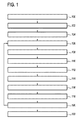
図1は医療機器の作動方法の一実施例を図示するフローチャートを示す。医療機器はイメージングゾーン内の被検者から磁気共鳴データを収集するために動作可能な磁気共鳴イメージングシステムを有する。磁気共鳴イメージングシステムは第一座標系を持つ。医療機器はターゲットゾーンを照射するために動作可能な外照射放射線治療システムをさらに有し、ターゲットゾーンはイメージングゾーン内にある。外照射放射線治療システムは第二座標系を持つ。医療機器は放射線ビームを生成するために動作可能な放射線ビーム生成システムをさらに有する。医療機器は第二座標系における放射線ビームを記述する放射線ビーム検出データを収集するために動作可能な放射線ビーム検出システムをさらに有する。方法はターゲットゾーンへの空間依存放射線量を記述するプランニングデータが受信されるステップ100で開始する。次にステップ102において外照射放射線治療制御コマンドが空間依存放射線量を用いて生成される。そしてステップ104においてターゲットゾーンの照射が開始される。
FIG. 1 shows a flow chart illustrating one embodiment of a method for operating a medical device. The medical device has a magnetic resonance imaging system operable to collect magnetic resonance data from subjects within the imaging zone. The magnetic resonance imaging system has a first coordinate system. The medical device further includes an external radiation radiation treatment system operable to illuminate the target zone, the target zone being within the imaging zone. The external radiation radiotherapy system has a second coordinate system. The medical device further includes a radiation beam generation system operable to generate the radiation beam. The medical device further includes a radiation beam detection system operable to collect radiation beam detection data describing the radiation beam in the second coordinate system. The method begins at
次にステップ106において外照射放射線治療システム制御コマンドを用いてターゲットゾーンを照射するために外照射放射線治療システムが使用される。次にステップ108において放射線ビームが放射線ビーム生成システムを用いて生成される。次にステップ110において放射線ビーム検出データが放射線ビーム検出システムを用いて測定される。次にステップ112において磁気共鳴イメージングシステムを用いて磁気共鳴イメージングデータが収集される。これに続きステップ114において磁気共鳴画像データを用いて磁気共鳴画像が生成若しくは再構成される。そしてステップ116において磁気共鳴画像が放射線ビーム検出データに位置合わせされる。この位置合わせは位置合わせを用いて第一座標系と第二座標系間のマッピングを計算するステップ118へと続く。次にステップ120において外照射放射線治療システム制御コマンドがマッピングを用いて修正される。被検者ターゲットゾーンの照射が完了する場合、方法はターゲットゾーンの照射を終了若しくは停止するステップ122へ進む。そうでなければ、方法はステップ106へ繰り返し、照射が終了する(122)までステップ106及び120の間のループが実行される。ステップ106‐120はターゲットゾーンの照射中の第一座標系と第二座標系間の相違における変化を考慮する閉ループ制御ループを形成する。
Next, in
図2は医療機器200の一実施例を示す。医療機器200は外照射放射線治療システム202と磁気共鳴イメージングシステム204を有する。外照射放射線治療システム202はガントリ206と放射線治療源208を有する。ガントリ206はガントリ回転軸240まわりに放射線治療源208を回転させるためのものである。放射線治療源208にコリメータ210が隣接する。磁気共鳴イメージングシステム204は磁石212を有する。
FIG. 2 shows an embodiment of the
永久磁石若しくは常伝導磁石を使用することも可能である。異なるタイプの磁石の使用も可能であり、例えばスプリット円筒磁石及びいわゆるオープン磁石の両方を使用することも可能である。スプリット円筒磁石は磁石のiso‐planeへのアクセスを可能にするためにクライオスタットが二つのセクションに分割されている点を除き、標準円筒磁石と同様であり、かかる磁石は例えば荷電粒子ビーム治療と併用して使用され得る。オープン磁石は被検者を受け入れるために十分な大きさの空間を間に持つ上下の二つの磁石セクションを持つ。二つのセクション領域の配置はヘルムホルツコイルのものと同様である。オープン磁石は、被検者があまり閉じ込められないので、一般的である。円筒磁石のクライオスタットの内部に、超電導コイルの集合がある。円筒磁石のボア内に、磁場が磁気共鳴イメージングを実行するために十分に強く均一である、イメージングゾーンがある。 It is also possible to use permanent magnets or normal conducting magnets. Different types of magnets can be used, for example both split cylindrical magnets and so-called open magnets can be used. A split cylindrical magnet is similar to a standard cylindrical magnet, except that the cryostat is divided into two sections to allow access to the magnet's iso-plane, such as in conjunction with charged particle beam therapy Can be used. An open magnet has two upper and lower magnet sections with a space large enough to accept the subject. The arrangement of the two section areas is similar to that of the Helmholtz coil. Open magnets are common because the subject is less confined. There is a collection of superconducting coils inside the cryostat of the cylindrical magnet. Within the bore of the cylindrical magnet is an imaging zone where the magnetic field is strong and uniform enough to perform magnetic resonance imaging.
この実施形態で示される磁石212は標準円筒超電導磁石である。磁石212はその中に超電導コイル216を伴うクライオスタット214を持つ。クライオスタット内に超電導シールドコイル218もある。磁石212はボア222を持つ。
The
磁石のボア内に、磁石のイメージングゾーン内の陽子スピンを空間エンコードする磁気共鳴データの収集のための傾斜磁場コイル224がある。傾斜磁場コイル224は傾斜磁場コイル電源226に接続される。傾斜磁場コイル224は代表例の意図であり、放射線が減衰されることなく通過することを可能にするために通常はスプリットコイルデザインになる。典型的に傾斜磁場コイルは三つの直交空間方向に空間エンコードするための三つの個別コイルセットを含む。傾斜磁場電源226は傾斜磁場コイルに電流を供給する。傾斜磁場コイルへ供給される電流は時間の関数として制御され、ランプ若しくはパルス化され得る。
Within the magnet bore is a
トランシーバ230に接続される高周波コイル228がある。高周波コイル228は磁石212のイメージングゾーン232に隣接する。イメージングゾーン232は磁気共鳴イメージングを実行するために十分な高磁場と均一性の領域を持つ。高周波コイル228はイメージングゾーン内の磁気スピンの配向を操作するため、及び同様にイメージングゾーン内のスピンからの無線伝送を受信するためのものであり得る。高周波コイル228はアンテナ若しくはチャネルともよばれ得る。高周波コイル228はマルチコイル素子を含み得る。高周波アンテナはチャネルともよばれ得る。
There is a
高周波コイル228及び高周波トランシーバ230は個別の送信及び受信コイル並びに個別の送信機と受信機によって置き換えられ得る。高周波コイルと高周波トランシーバは代表例であることが理解される。高周波アンテナは専用送信アンテナ及び専用受信アンテナもあらわすことが意図される。同様にトランシーバは個別送信機と受信機もあらわし得る。
The
磁石222のボア内に被検者236を支持するための被検者支持台234もある。被検者支持台234は機械的ポジショニングシステム237によってポジショニングされ得る。被検者236内にターゲットゾーン238がある。ガントリ回転軸240はこの特定の実施形態において磁石212の円筒軸と同軸である。被検者支持台234はガントリ回転軸240上にターゲットゾーン238があるようにポジショニングされている。放射線源208はコリメータ203とターゲットゾーン238を通過する放射線ビーム242を生成するように示される。放射線源208は軸240まわりに回転されるのでターゲットゾーン238は常に放射線ビーム242のターゲットとされる。放射線ビーム242は磁石のクライオスタット214を通過する。傾斜磁場コイルは傾斜磁場コイルを二セクションへ分離するギャップを持ち得る。存在する場合、このギャップは傾斜磁場コイル224による放射線ビーム242の減衰を軽減する。一部の実施形態において高周波コイル228も放射線ビーム242の減衰を軽減するためにギャップを持つか若しくは分離され得る。
There is also a
ガントリ206上に取り付けられるポータルイメージングシステム243が図示される。ポータルイメージングシステム243は放射線ビーム242を用いて画像を収集することができる。ガントリが回転すると、ポータルイメージングシステムは放射線治療源とともに回転する。この実施例において磁石212は円筒型磁石であるとして図示され、放射線ビーム242はクライオスタット214を通過する。異なるタイプの磁石も使用され得る。二つの円筒セクションに分割され得るいわゆるスプリット磁石が使用されてもよく、放射線ビーム242はクライオスタット214を通る代わりに空気を通過し得る。二つのトロイダル磁石を持ついわゆるオープン磁石もステップ2において使用され得る。これらの代替的磁石デザインは放射線ビーム242がクライオスタット214を通過しないという利点を持ち得る。これはよりよいポータル画像をもたらし得る。
A
トランシーバ230、傾斜磁場コイル電源226、及び機械的ポジショニングシステム237は全てコンピュータシステム244のハードウェアインターフェース246に接続されるものとして示される。コンピュータシステム244はマシン実行可能命令を実行するため及び治療装置の動作と機能を制御するためのプロセッサ248をさらに有するものとして示される。ハードウェアインターフェース246はプロセッサ248が医療機器200と相互作用しそれを制御することを可能にする。プロセッサ248はさらにユーザインターフェース250、コンピュータストレージ252、及びコンピュータメモリ254へ接続されるものとして示される。
コンピュータストレージ252はプランニングデータ260を含むものとして示される。プランニングデータ260はターゲットゾーン238への所望の放射線量を記述する空間依存データを含む。コンピュータストレージ252はさらにパルスシーケンス262を含むものとして示される。パルスシーケンス262はプロセッサ248が磁気共鳴データを収集するように磁気共鳴イメージングシステム204を制御することを可能にする。コンピュータストレージ252はさらにプランニングデータ260から生成された外照射放射線治療システム制御コマンド264を含むものとして示される。コンピュータストレージ252はさらにパルスシーケンス262を用いて磁気共鳴イメージングシステム204で収集された磁気共鳴データ266を含むものとして示される。コンピュータストレージ252はさらに磁気共鳴画像268を含むものとして示される。
磁気共鳴画像268は磁気共鳴データ266から再構成された。コンピュータストレージ252はさらにポータルイメージングシステム243を用いて収集された放射線ビーム検出データ270を含むものとして示される。コンピュータストレージ252はさらに放射線ビーム検出データ270から再構成されたポータル画像272を含むものとして示される。コンピュータストレージ252はさらにポータル画像272と磁気共鳴画像268間の位置合わせ274を含むものとして示される。コンピュータストレージ252はさらにマッピング276を含むものとして示される。マッピング276は磁気共鳴イメージングシステム204の第一座標系と外照射放射線治療システム202に属する第二座標系の間でなされる。
コンピュータメモリ254は制御モジュールを含むものとして示される。制御モジュール280はプロセッサ248が医療機器200の動作と機能を制御することを可能にするコンピュータ実行可能コードを含む。例えば制御モジュール280はプロセッサ248がパルスシーケンス262を使用して磁気共鳴データ266を収集することを可能にし得る。コンピュータメモリ254はさらに制御コマンド生成モジュール282を含むものとして示される。制御コマンド生成モジュール282はプロセッサ248がプランニングデータ260から外照射放射線治療システム制御コマンド264を生成することを可能にするコードを含む。制御コマンド生成モジュール282はプロセッサ248がマッピング276に従って若しくはそれを用いて外照射放射線治療システム制御コマンド264へ訂正を行うことを可能にするコードも含む。
コンピュータメモリ254は画像再構成モジュール284をさらに含むものとして示される。画像再構成モジュール284はプロセッサ248が磁気共鳴データ266から磁気共鳴画像268を、及び放射線ビーム検出データ270からポータル画像272も再構成することを可能にするコンピュータ実行可能コードを含む。コンピュータメモリ254はさらに位置合わせモジュール286を含むものとして示される。位置合わせモジュール286はプロセッサ248がポータル画像272の磁気共鳴画像268への位置合わせ274などの画像処理タスクを実行することを可能にするコンピュータ実行可能コードを含む。画像位置合わせモジュール286は解剖学的ランドマークを識別するため又は識別マークを伴う原子の存在若しくは被検者236のシルエットを識別するためにもプログラムされ得る。
図3は図2に示すものと同様の医療機器300を示す。しかしながら、この実施形態では図示の二つの狭ビームX線生成器302が磁石212の外面に取り付けられる。それらは狭ビームX線304を生成するときにポータルカメラ243に衝突することを目的とする。狭ビームX線304の画像がポータル画像272上に現れる場所から、第一座標系と第二座標系間のマッピング276が推測され得る。ガントリが放射線治療源とポータルイメージングシステムとともに回転するポータルイメージングシステム243の回転を考慮するために磁気共鳴イメージングシステム204上に取り付けられる複数の狭ビームX線生成器があり得る。
FIG. 3 shows a
図4は図2及び3におけるものと同様に示される医療機器400を示す。図2と比較して、図4は被検者支持台234がファントム402を含む点で図2と異なる。ファントム402はイメージングゾーン232内にあり、磁気共鳴画像268内で可視である。ファントムは磁気共鳴画像においてコントラストを示す二つ以上の材料から構成され得る。二つ以上の材料はそれらがポータル画像272において可視になるようにX線タイプ画像においてもコントラストを示し得る。放射線ビーム242はファントム402を通過するものとして示される。位置合わせ274はポータル画像272を磁気共鳴画像268と比較し、両画像においてファントム402の位置を注記することによって決定され得る。
FIG. 4 shows a
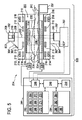
図5は図2、3及び4に示すものと同様の医療機器500を示す。図2と比較して、図5の医療機器500は磁石212の外面上に取り付けられる二つの狭ビームX線生成器302'、302"がある点で異なる。狭X線ビーム源302'はガントリ206上に取り付けられるX線検出センサアレイ502に向けられる狭ビームX線304'を生じる。一部の実施形態においてセンサアレイ302は磁石212に対して位置固定され、ガントリ206とともに回転しない。他の実施形態ではガントリ206とともに回転する多数のセンサ502があり得る。いずれの場合にもセンサアレイ502は狭X線ビーム304'を検出し、外照射放射線治療システム202の位置に対するMRIシステム204の位置を決定することができる。多数のセンサ502がありそれらがガントリ206とともに回転する場合、センサ502は磁石212の座標系に対する放射線治療源208の回転位置を検出することもできる。外照射放射線治療システム202はその上に取り付けられる第二センサアレイ502'を持つベース若しくは台も持つ。狭X線ビーム源302"は第二センサアレイ302'に狭ビームX線304"を向ける。センサアレイ502'は外照射放射線治療システム202に対する磁気共鳴イメージングシステム204の位置を記述するデータも提供する。狭X線ビーム源302'、302"の一方若しくは両方が存在し得る。
FIG. 5 shows a
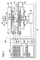
図6は図2‐5に示す医療機器と多くの点で同様である医療機器600を示す。ポータルイメージングシステム243とオプションの狭ビームX線生成器302もある。この実施例では陽子ビーム602がターゲットゾーン238の方へ向けられる。陽子ビームはこの図には示されない粒子加速器604によって与えられる。荷電粒子若しくは陽子ビームオブジェクト606は陽子のビーム602をとりそれをターゲットゾーン238の方へ向ける。この実施例ではいわゆるスプリット磁石が使用される。磁石212'、212"は二等分される。RFコイルも陽子ビーム602が通過するためのギャップを持つものとして示される。RFコイル228及び被検者支持台234はギャップを持つものとして示されないが、それらは陽子ビーム602が最小減衰で移動するのを支援するためにギャップを持つこともできる。この実施例ではポータルカメラ243が陽子ビーム602によって生成される放射線を用いて被検者236の基本画像を作り出すために使用される。
FIG. 6 shows a
図7は図3に示すものと同様の医療機器700の一実施形態を示す。しかしながら図7に示す実施例ではスプリット磁石デザインが使用される。磁石は二等分212'及び212"から成る。放射線ビーム242は磁石の二等分212'、212"間のギャップにおいて自由に通過することができる。
FIG. 7 shows one embodiment of a
統合MR‐Linacシステムの場合、各座標系間の正確なコ位置合わせ(アライメント)は手術及び臨床用途にとって有用である。規制はかかる重要なシステムパラメータの恒常的品質保証を要する。幾何公差を最小化しシステムの機械的安定性を増すためにシステムの設計中に高水準が採用されなければならない。システムの大きな寸法及びサイズ並びに変化する周辺パラメータ(例えば温度)は、しかしながら完全なアライメントからの逸脱につながり得る。これらの逸脱は画像化される解剖学的構造の位置(MR)と適用される治療照射の仮定対応位置(Linac)間のミスマッチにつながり得る。そしてこれは誤った処置をもたらし得る。患者にとって明らかな可能性のあるマイナスの副作用は別にして、これは厳密な規制の結果につながり得る。 For integrated MR-Linac system, precise co alignment between the coordinate system (alignment) is useful for surgical and clinical applications. Regulations require constant quality assurance of such important system parameters. High standards must be employed during system design to minimize geometric tolerances and increase the mechanical stability of the system. The large dimensions and size of the system and changing ambient parameters (eg temperature), however, can lead to deviations from perfect alignment. These deviations can lead to mismatches between the position of the anatomical structure being imaged (MR) and the hypothetical corresponding position (Linac) of the applied treatment irradiation. And this can lead to incorrect treatment. Apart from the negative side effects that may be apparent to the patient, this can lead to strict regulatory consequences.
MR‐Linacシステムのサブシステムのミスアライメント(例えば機械公差、システム構造の変形、周辺の影響に起因する)のモニタリングの失敗は、気付かれない誤った処置及び危険な結果につながり得る。 Failure to monitor MR-Linac system subsystem misalignments (e.g., due to machine tolerances, system structure deformations, ambient effects) can lead to unacknowledged mishandling and dangerous consequences.
本明細書の医療機器の実施例は画像処理手段と、オプションとして統合X線ナビゲータを利用して、MR及びLinacの座標系のアライメントを決定しモニタリングし得る。必要な測定は治療前、治療中、及び治療後レジームでなされ得る。測定データのコ位置合わせはシステム間の現在の変換の決定を非常に迅速に可能にする。そしてこれらの変換パラメータは逸脱についてイメージングとプランを補正する、又は治療を中止するために使用され得る。 The medical device embodiments herein may utilize image processing means and optionally an integrated X-ray navigator to determine and monitor the alignment of the MR and Linac coordinate systems. The necessary measurements can be made before, during, and after treatment regimes. Co- alignment of the measurement data makes it possible to determine the current conversion between systems very quickly. These transformation parameters can then be used to correct imaging and plans for deviations or to stop treatment.
MR‐Linacシステム内に含まれるx線検出器と放射線源を利用して画像が生成され得る(ポータルイメージングとして知られる)。放射線の高エネルギー及び組織の吸収特性のために、かかる画像の品質は限られる。しかしながらランドマークを識別すれば十分である。追加解剖学情報(例えばターゲットのセグメンテーション、OAR及び体の輪郭、既知の位置への患者固定)と併せて対応するランドマークが(自動的に)MR画像において識別され得る。これらのランドマークは点若しくは面であり得る(コーンビームCTポータルイメージング及び3D MRデータに基づく)。 Images can be generated utilizing an x-ray detector and radiation source included in the MR-Linac system (known as portal imaging). Due to the high energy of radiation and the absorption characteristics of the tissue, the quality of such images is limited. However, it is sufficient to identify the landmark. Corresponding landmarks can be (automatically) identified in the MR image along with additional anatomical information (eg, target segmentation, OAR and body contours, patient fixation in a known location). These landmarks can be points or planes (based on cone beam CT portal imaging and 3D MR data).
そして二つのデータセット間の(アフィン)変換を計算することが可能である。そしてこれらの変換パラメータは連続画像データを変換するか若しくはアライメントの逸脱が大きくなり過ぎる場合に治療を中止するために使用され得る。この方法はセッションの前、最中若しくは後に短時間で利用され得る。 It is then possible to calculate the (affine) transformation between the two data sets. These conversion parameters can then be used to convert the continuous image data or to stop treatment if the alignment deviation becomes too great. This method can be used in a short time before, during or after the session.
オプションとしていくつかの小さなX線源(例えば小型デザイン若しくはナノチューブベース)がMRシステム(例えばクライオスタット)の内部/上に置かれ、"ナビゲータ"(又はスパースサンプリング最小投射"画像")となり、Linacガントリ上に置かれるポータルイメージング検出器若しくはいくつかのマイクロ検出器の方へ向けられることができる。ポータルイメージングアプローチと同様にこの情報はその後ポータルイメージングに起因する追加の患者線量及びイメージング時間を伴わずにコ位置合わせのために使用されることができ、正確なアライメントのリアルタイムモニタリングを可能にする。 Optionally, several small x-ray sources (eg small design or nanotube based) are placed inside / on the MR system (eg cryostat) to become a “navigator” (or sparse sampling minimum projection “image”) on the Linac gantry Can be directed towards a portal imaging detector or several micro-detectors placed in Similar to the portal imaging approach, this information can then be used for co- alignment without the additional patient dose and imaging time resulting from portal imaging, allowing real-time monitoring of accurate alignment.
座標系の位置合わせは(ポータルイメージングに基づく)プラン適応及び線量蓄積(Q&A)のための構造の吸収特性を導出することも可能にする。 Coordinate system alignment also makes it possible to derive the absorption characteristics of the structure for plan adaptation (based on portal imaging) and dose accumulation (Q & A).
本発明は図面と先の説明において詳細に図示され記載されているが、かかる図示と記載は例示若しくは説明であって限定ではないとみなされる。本発明は開示の実施形態に限定されない。 While the invention has been illustrated and described in detail in the drawings and foregoing description, such illustration and description are to be considered illustrative or exemplary and not restrictive; The invention is not limited to the disclosed embodiments.
開示の実施形態への他の変更は、図面、開示、及び添付の請求項の考察から、請求される発明を実施する上で当業者によって理解されもたらされることができる。請求項において、"有する"という語は他の要素若しくはステップを除外せず、不定冠詞"a"若しくは"an"は複数を除外しない。単一プロセッサ若しくは他のユニットは請求項に列挙される複数の項目の機能を満たし得る。特定の手段が相互に異なる従属請求項に列挙されるという単なる事実はこれら手段の組み合わせが有利に使用されることができないことを示さない。コンピュータプログラムは、他のハードウェアと一緒に又はその一部として供給される光学記憶媒体若しくはソリッドステート媒体などの適切な媒体上に格納/分散され得るが、インターネット又は他の有線若しくは無線通信システムなどを介して他の形式で分散されてもよい。請求項におけるいかなる参照符号も範囲を限定するものと解釈されてはならない。
Other changes to the disclosed embodiments can be understood and effected by those skilled in the art in practicing the claimed invention, from a study of the drawings, the disclosure, and the appended claims. In the claims, the word “comprising” does not exclude other elements or steps, and the indefinite article “a” or “an” does not exclude a plurality. A single processor or other unit may fulfill the functions of several items recited in the claims. The mere fact that certain measures are recited in mutually different dependent claims does not indicate that a combination of these measured cannot be used to advantage. The computer program may be stored / distributed on suitable media such as optical storage media or solid state media supplied with or as part of other hardware, such as the Internet or other wired or wireless communication systems, etc. It may be distributed in other forms via Any reference signs in the claims should not be construed as limiting the scope.
200 医療機器
202 外照射放射線治療システム
204 磁気共鳴イメージングシステム
206 ガントリ
208 放射線治療源
210 コリメータ
212 磁石
212' スプリット磁石の一部
212" スプリット磁石の一部
214 クライオスタット
216 超電導コイル
218 超電導シールドコイル
222 ボア
224 傾斜磁場コイル
226 傾斜磁場コイル電源
228 高周波コイル
230 トランシーバ
232 イメージングゾーン
234 被検者支持台
236 被検者
237 機械的ポジショニングシステム
238 ターゲットゾーン
240 ガントリ回転軸
242 放射線ビーム
243 ポータルイメージングシステム
244 コンピュータシステム
246 ハードウェアインターフェース
248 プロセッサ
250 ユーザインターフェース
252 コンピュータストレージ
254 コンピュータメモリ
260 プランニングデータ
262 パルスシーケンス
264 外照射放射線治療システム制御コマンド
266 磁気共鳴データ
268 磁気共鳴画像
270 放射線ビーム検出データ
272 ポータル画像
274 位置合わせ
276 マッピング
280 制御モジュール
282 制御コマンド生成モジュール
284 画像再構成モジュール
286 位置合わせモジュール
300 医療機器
302 狭ビームX線生成器
302' 狭ビームX線生成器
302" 狭ビームX線生成器
304 狭ビームX線
304' 狭ビームX線
304" 狭ビームX線
400 医療機器
402 ファントム
500 医療機器
502 X線検出センサアレイ
502' X線検出センサアレイ
600 医療機器
601 陽子ビーム源
602 陽子ビーム
604 粒子加速器
606 陽子ビーム光学
700 医療機器
200
Claims (12)
前記イメージングゾーン内にあるターゲットゾーンを照射するために動作可能な外照射放射線治療システムであって、第二座標系を持つ、外照射放射線治療システムと、
治療効果を持つ高エネルギ放射線ビームを生成するために動作可能な放射線ビーム生成システムと、
前記第二座標系における前記放射線ビームを記述する放射線ビーム検出データを収集するために動作可能な放射線ビーム検出システムと、
マシン実行可能命令を格納するためのメモリと、
前記マシン実行可能命令を実行するためのプロセッサであって、当該命令の実行が当該プロセッサに、前記ターゲットゾーンの空間的部分に供給される放射線量を示す空間依存放射線量を記述するプランニングデータを受信させ、当該命令の実行がさらに当該プロセッサに、前記空間依存放射線量を用いて外照射放射線治療システム制御コマンドを生成させる、プロセッサと
を有する、医療機器において、
前記命令の実行が前記プロセッサに、繰り返し、
前記外照射放射線治療システム制御コマンドを使用して前記ターゲットゾーンを照射するように前記外照射放射線治療システムを制御させ、
前記放射線ビーム生成システムを用いて前記放射線ビームを生成させ、
前記放射線ビーム検出システムを用いて前記放射線ビーム検出データを測定させ、
前記磁気共鳴イメージングシステムを用いて前記磁気共鳴データを収集させ、
前記磁気共鳴データを用いて磁気共鳴画像を生成させ、
前記磁気共鳴画像の前記放射線ビーム検出データへの位置合わせを決定させ、
前記位置合わせを用いて前記第一座標系と前記第二座標系間の相対座標を決定させ、
前記相対座標を用いて前記外照射放射線治療システム制御コマンドを修正させ、
前記放射線ビーム検出システムが前記被検者の放射線画像を収集するための放射線イメージングシステムを有し、前記放射線画像は、前記放射線ビーム検出データが前記放射線画像を有するので前記高エネルギ放射線ビームによって伝えられ、前記命令の実行がさらに前記プロセッサに、前記磁気共鳴画像へ前記放射線画像を位置合わせすることによって前記相対座標を決定させ、
前記命令の実行がさらに前記プロセッサに、前記相対座標が第一既定閾値よりも大きい前記第一座標系と前記第二座標系間の差を示す場合、前記ターゲットゾーンの照射を中止するように前記外照射放射線治療システムを制御すること、ディスプレイ上に警告メッセージを表示すること、前記外照射放射線治療システムの照射を自動的に調節すること、前記磁気共鳴データの収集を自動的に調節すること、前記相対座標における時間的変化が第二既定閾値よりも大きい場合、前記ターゲットゾーンの照射を中止するように前記外照射放射線治療システムを制御すること、並びにそれらの組み合わせ、のうちいずれか一つを実行させる、
医療機器。 A magnetic resonance imaging system operable to collect magnetic resonance data from a subject in an imaging zone, the magnetic resonance imaging system having a first coordinate system;
An external radiation radiotherapy system operable to illuminate a target zone within the imaging zone, the external radiation radiotherapy system having a second coordinate system;
A radiation beam generation system operable to generate a high energy radiation beam having a therapeutic effect;
A radiation beam detection system operable to collect radiation beam detection data describing the radiation beam in the second coordinate system;
Memory for storing machine-executable instructions;
A processor for executing the machine-executable instructions, wherein execution of the instructions receives planning data describing a spatially dependent radiation dose indicative of the radiation dose delivered to a spatial portion of the target zone upon execution of the instruction. And the execution of the instructions further causes the processor to generate an external radiation therapy system control command using the space-dependent radiation dose.
Execution of the instruction is repeated to the processor;
Controlling the external radiation radiotherapy system to illuminate the target zone using the external radiation radiotherapy system control command;
Generating the radiation beam using the radiation beam generating system;
Using the radiation beam detection system to measure the radiation beam detection data;
Collecting the magnetic resonance data using the magnetic resonance imaging system;
Generating a magnetic resonance image using the magnetic resonance data;
Determining the alignment of the magnetic resonance image to the radiation beam detection data;
Using the alignment to determine relative coordinates between the first coordinate system and the second coordinate system;
Using the relative coordinates to modify the external radiation therapy system control command;
The radiation beam detection system includes a radiation imaging system for collecting a radiation image of the subject, and the radiation image is transmitted by the high energy radiation beam because the radiation beam detection data comprises the radiation image. The execution of the instructions further causes the processor to determine the relative coordinates by aligning the radiographic image to the magnetic resonance image;
If the execution of the instruction further indicates to the processor that the relative coordinate is greater than a first predetermined threshold between the first coordinate system and the second coordinate system, the irradiation of the target zone is stopped. Controlling an external radiation therapy system; displaying a warning message on a display; automatically adjusting the radiation of the external radiation therapy system; automatically adjusting the collection of the magnetic resonance data; If the temporal change in the relative coordinates is greater than a second predetermined threshold, controlling the external irradiation radiotherapy system to stop the irradiation of the target zone, and any combination thereof To execute,
Medical equipment.
前記放射線画像における前記被検者の解剖学的ランドマークを識別させ、
前記磁気共鳴画像において前記解剖学的ランドマークを識別させ、前記磁気共鳴画像への前記放射線画像の位置合わせが前記解剖学的ランドマークを用いて少なくとも部分的に実行される、
請求項2に記載の医療機器。 Execution of the instructions is further to the processor;
Identifying the subject's anatomical landmarks in the radiographic image;
Identifying the anatomical landmark in the magnetic resonance image, and alignment of the radiographic image to the magnetic resonance image is at least partially performed using the anatomical landmark;
The medical device according to claim 2.
前記命令の実行がさらに前記プロセッサに、繰り返し、
前記外照射放射線治療システム制御コマンドを使用して前記ターゲットゾーンを照射するように前記外照射放射線治療システムを制御させ、
前記放射線ビーム生成システムを用いて前記放射線ビームを生成させ、
前記放射線ビーム検出システムを用いて前記放射線ビーム検出データを測定させ、
前記磁気共鳴イメージングシステムを用いて前記磁気共鳴データを収集させ、
前記磁気共鳴データを用いて磁気共鳴画像を再構成させ、
前記磁気共鳴画像と前記放射線ビーム検出データ間の位置合わせを決定させ、
前記位置合わせを用いて前記第一座標系と前記第二座標系間の相対座標を決定させ、
前記相対座標を用いて前記外照射放射線治療システム制御コマンドを修正させ、
前記放射線ビーム検出システムが前記被検者の放射線画像を収集するための放射線イメージングシステムを有し、前記放射線画像は、前記放射線ビーム検出データが前記放射線画像を有するので前記高エネルギ放射線ビームによって伝えられ、前記命令の実行がさらに前記プロセッサに、前記磁気共鳴画像へ前記放射線画像を位置合わせすることによって前記相対座標を決定させ、
前記命令の実行がさらに前記プロセッサに、前記相対座標が第一既定閾値よりも大きい前記第一座標系と前記第二座標系間の差を示す場合、前記ターゲットゾーンの照射を中止するように前記外照射放射線治療システムを制御すること、ディスプレイ上に警告メッセージを表示すること、前記外照射放射線治療システムの照射を自動的に調節すること、前記磁気共鳴データの収集を自動的に調節すること、前記相対座標における時間的変化が第二既定閾値よりも大きい場合、前記ターゲットゾーンの照射を中止するように前記外照射放射線治療システムを制御すること、並びにそれらの組み合わせ、のうちいずれか一つを実行させる、
コンピュータプログラム製品。 A computer program product having machine-executable instructions for execution by a processor that controls a medical device, the medical device operable to collect magnetic resonance data from a subject in an imaging zone The magnetic resonance imaging system has a first coordinate system, and the medical device further comprises an external radiation therapy system operable to irradiate a target zone within the imaging zone, The irradiation radiotherapy system has a second coordinate system, the medical device further includes a radiation beam generation system operable to generate a high-energy radiation beam having a therapeutic effect, the medical device comprising the second coordinate system For collecting radiation beam detection data describing the radiation beam in Further comprising an operable radiation beam detection system, wherein execution of the instructions causes the processor to receive planning data describing a spatially dependent radiation dose indicative of a radiation dose delivered to a spatial portion of the target zone; Execution of instructions further causes the processor to generate an external radiation therapy system control command using the space-dependent radiation dose,
Execution of the instructions is further repeated in the processor;
Controlling the external radiation radiotherapy system to illuminate the target zone using the external radiation radiotherapy system control command;
Generating the radiation beam using the radiation beam generating system;
Using the radiation beam detection system to measure the radiation beam detection data;
Collecting the magnetic resonance data using the magnetic resonance imaging system;
Reconstructing a magnetic resonance image using the magnetic resonance data;
Determining an alignment between the magnetic resonance image and the radiation beam detection data;
Using the alignment to determine relative coordinates between the first coordinate system and the second coordinate system;
Using the relative coordinates to modify the external radiation therapy system control command;
The radiation beam detection system includes a radiation imaging system for collecting a radiation image of the subject, and the radiation image is transmitted by the high energy radiation beam because the radiation beam detection data comprises the radiation image. The execution of the instructions further causes the processor to determine the relative coordinates by aligning the radiographic image to the magnetic resonance image;
If the execution of the instruction further indicates to the processor that the relative coordinate is greater than a first predetermined threshold between the first coordinate system and the second coordinate system, the irradiation of the target zone is stopped. Controlling an external radiation therapy system; displaying a warning message on a display; automatically adjusting the radiation of the external radiation therapy system; automatically adjusting the collection of the magnetic resonance data; If the temporal change in the relative coordinates is greater than a second predetermined threshold, controlling the external irradiation radiotherapy system to stop the irradiation of the target zone, and any combination thereof To execute,
Computer program product.
Applications Claiming Priority (3)
| Application Number | Priority Date | Filing Date | Title |
|---|---|---|---|
| EP13186655 | 2013-09-30 | ||
| EP13186655.0 | 2013-09-30 | ||
| PCT/EP2014/070079 WO2015044065A1 (en) | 2013-09-30 | 2014-09-22 | Alignment of the coordinate systems of external beam radiotherapy amd magnetic resonance imaging systems |
Publications (3)
| Publication Number | Publication Date |
|---|---|
| JP2016538092A JP2016538092A (en) | 2016-12-08 |
| JP2016538092A5 JP2016538092A5 (en) | 2019-05-30 |
| JP6568077B2 true JP6568077B2 (en) | 2019-08-28 |
Family
ID=49293511
Family Applications (1)
| Application Number | Title | Priority Date | Filing Date |
|---|---|---|---|
| JP2016544746A Active JP6568077B2 (en) | 2013-09-30 | 2014-09-22 | Coordinate system alignment of externally irradiated radiotherapy and magnetic resonance imaging systems |
Country Status (6)
| Country | Link |
|---|---|
| US (1) | US10543380B2 (en) |
| EP (1) | EP3052187B1 (en) |
| JP (1) | JP6568077B2 (en) |
| CN (1) | CN105611967B (en) |
| RU (1) | RU2677049C2 (en) |
| WO (1) | WO2015044065A1 (en) |
Families Citing this family (13)
| Publication number | Priority date | Publication date | Assignee | Title |
|---|---|---|---|---|
| JP6475234B2 (en) * | 2013-06-21 | 2019-02-27 | コーニンクレッカ フィリップス エヌ ヴェKoninklijke Philips N.V. | Cryostat and system for combined magnetic resonance imaging and radiotherapy |
| WO2016138083A1 (en) * | 2015-02-24 | 2016-09-01 | Massachusetts Institute Of Technology | Toroidal bending magnets for hadron therapy gantries |
| US10635930B2 (en) * | 2017-02-24 | 2020-04-28 | Siemens Healthcare Gmbh | Patient position control for scanning |
| GB2561373A (en) * | 2017-04-11 | 2018-10-17 | Elekta ltd | Radiotherapy apparatus with calibration |
| WO2019113839A1 (en) | 2017-12-13 | 2019-06-20 | Shenzhen United Imaging Healthcare Co., Ltd. | System and method for diagnosis and treatment |
| GB2571124A (en) * | 2018-02-19 | 2019-08-21 | Elekta ltd | Method and apparatus for beam energy measurement |
| US11654302B2 (en) * | 2018-05-09 | 2023-05-23 | University Of Florida Research Foundation, Incorporated | Systems and methods for particle portal imaging |
| CN111107900B (en) | 2018-11-14 | 2022-03-04 | 上海联影医疗科技股份有限公司 | Radiation therapy system |
| CN111951925B (en) * | 2019-05-17 | 2024-01-30 | 南京巨鲨显示科技有限公司 | System and method for determining injection dosage of radioactive drug |
| CN110582328B (en) * | 2019-07-22 | 2022-03-01 | 北京市肿瘤防治研究所 | Radiotherapy emergent beam monitoring method and system |
| EP4010720A4 (en) * | 2019-08-05 | 2023-08-09 | The Board Of Regents Of The University Of Texas System | Inhomogeneous mri system |
| US11433258B2 (en) * | 2019-10-18 | 2022-09-06 | Uih-Rt Us Llc | System and method for dose measurement in radiation therapy |
| CN110787376B (en) * | 2019-11-29 | 2021-04-06 | 合肥中科离子医学技术装备有限公司 | Tumor patient positioning system based on proton imaging |
Family Cites Families (14)
| Publication number | Priority date | Publication date | Assignee | Title |
|---|---|---|---|---|
| US6519316B1 (en) | 2001-11-02 | 2003-02-11 | Siemens Medical Solutions Usa, Inc.. | Integrated control of portal imaging device |
| US7564950B2 (en) | 2006-02-17 | 2009-07-21 | Siemens Medical Solutions Usa, Inc. | Multi-leaf collimator based field size clipping for automatic adaptation to allowed image area |
| JP4126318B2 (en) * | 2006-06-23 | 2008-07-30 | 三菱重工業株式会社 | Radiotherapy apparatus control apparatus and radiotherapy apparatus control method |
| DE102008007245B4 (en) | 2007-02-28 | 2010-10-14 | Siemens Aktiengesellschaft | Combined radiotherapy and magnetic resonance device |
| US8249317B2 (en) | 2007-07-20 | 2012-08-21 | Eleckta Ltd. | Methods and systems for compensating for changes in anatomy of radiotherapy patients |
| US8331531B2 (en) * | 2009-03-13 | 2012-12-11 | The Board Of Trustees Of The Leland Stanford Junior University | Configurations for integrated MRI-linear accelerators |
| US8836332B2 (en) | 2009-07-15 | 2014-09-16 | Viewray Incorporated | Method and apparatus for shielding a linear accelerator and a magnetic resonance imaging device from each other |
| US9108048B2 (en) | 2010-08-06 | 2015-08-18 | Accuray Incorporated | Systems and methods for real-time tumor tracking during radiation treatment using ultrasound imaging |
| JP5832079B2 (en) * | 2010-10-01 | 2015-12-16 | キヤノン株式会社 | Connection device and printing device |
| US10124190B2 (en) * | 2010-12-16 | 2018-11-13 | Koninklijke Philips N.V. | Radiation therapy planning and follow-up system with large bore nuclear and magnetic resonance imaging or large bore CT and magnetic resonance imaging |
| US9364687B2 (en) * | 2011-01-21 | 2016-06-14 | Headwater Partners Ii Llc | Imaging observation timing based on radiation treatment system element delay |
| CN102631215A (en) * | 2011-02-14 | 2012-08-15 | 杨光蕾 | Method and device for reducing radiation dosage of X rays in human transmission inspection |
| CN103620437B (en) * | 2011-06-27 | 2017-10-27 | 皇家飞利浦有限公司 | Use the bone MRI of the fatty separating treatment of ultrashort echo time pulse train and water with FID and many gradient echo acquisitions |
| RU2011126922A (en) * | 2011-07-01 | 2013-01-10 | Открытое акционерное общество "Головной центр сервисного обслуживания и ремонта Концерна ПВО "Алмаз-Антей" "Гранит" | METHOD FOR IRRADIATING MALIGNANT TUMORS OF THE PROSTATE GLAND BY A BEAM OF HADRONS AND A DEVICE FOR ITS IMPLEMENTATION |
-
2014
- 2014-09-22 WO PCT/EP2014/070079 patent/WO2015044065A1/en active Application Filing
- 2014-09-22 US US15/025,302 patent/US10543380B2/en active Active
- 2014-09-22 JP JP2016544746A patent/JP6568077B2/en active Active
- 2014-09-22 EP EP14772316.7A patent/EP3052187B1/en active Active
- 2014-09-22 CN CN201480053959.XA patent/CN105611967B/en active Active
- 2014-09-22 RU RU2016116904A patent/RU2677049C2/en active
Also Published As
| Publication number | Publication date |
|---|---|
| EP3052187A1 (en) | 2016-08-10 |
| US20160213951A1 (en) | 2016-07-28 |
| JP2016538092A (en) | 2016-12-08 |
| WO2015044065A1 (en) | 2015-04-02 |
| CN105611967B (en) | 2019-05-14 |
| US10543380B2 (en) | 2020-01-28 |
| RU2016116904A3 (en) | 2018-05-31 |
| RU2677049C2 (en) | 2019-01-15 |
| EP3052187B1 (en) | 2018-11-14 |
| CN105611967A (en) | 2016-05-25 |
| RU2016116904A (en) | 2017-11-10 |
Similar Documents
| Publication | Publication Date | Title |
|---|---|---|
| JP6568077B2 (en) | Coordinate system alignment of externally irradiated radiotherapy and magnetic resonance imaging systems | |
| JP6113919B2 (en) | Medical device with radiation therapy device and radiation detection system | |
| US9662512B2 (en) | Magnetic resonance guided LINAC | |
| JP6865802B2 (en) | RF coil positioning system | |
| JP2016538092A5 (en) | ||
| JP6348902B2 (en) | Magnetic resonance induction therapy by interleave scanning | |
| CN105792894B (en) | Medical instrument for external beam radiotherapy and brachytherapy | |
| US20200054234A1 (en) | Radiotherapy system for accurate locating of 3d objects from magnetic resonance images | |
| US20220299587A1 (en) | Synthetic four-dimensional computed tomographic image generation | |
| EP3381362A1 (en) | Magnetic resonance image quality determination |
Legal Events
| Date | Code | Title | Description |
|---|---|---|---|
| RD04 | Notification of resignation of power of attorney |
Free format text: JAPANESE INTERMEDIATE CODE: A7424 Effective date: 20170214 |
|
| A521 | Request for written amendment filed |
Free format text: JAPANESE INTERMEDIATE CODE: A523 Effective date: 20170905 |
|
| A621 | Written request for application examination |
Free format text: JAPANESE INTERMEDIATE CODE: A621 Effective date: 20170905 |
|
| A977 | Report on retrieval |
Free format text: JAPANESE INTERMEDIATE CODE: A971007 Effective date: 20180618 |
|
| A521 | Request for written amendment filed |
Free format text: JAPANESE INTERMEDIATE CODE: A523 Effective date: 20180620 |
|
| A871 | Explanation of circumstances concerning accelerated examination |
Free format text: JAPANESE INTERMEDIATE CODE: A871 Effective date: 20180620 |
|
| A975 | Report on accelerated examination |
Free format text: JAPANESE INTERMEDIATE CODE: A971005 Effective date: 20180621 |
|
| A131 | Notification of reasons for refusal |
Free format text: JAPANESE INTERMEDIATE CODE: A131 Effective date: 20180705 |
|
| A521 | Request for written amendment filed |
Free format text: JAPANESE INTERMEDIATE CODE: A523 Effective date: 20181003 |
|
| A02 | Decision of refusal |
Free format text: JAPANESE INTERMEDIATE CODE: A02 Effective date: 20190108 |
|
| A524 | Written submission of copy of amendment under article 19 pct |
Free format text: JAPANESE INTERMEDIATE CODE: A524 Effective date: 20190405 |
|
| A911 | Transfer to examiner for re-examination before appeal (zenchi) |
Free format text: JAPANESE INTERMEDIATE CODE: A911 Effective date: 20190415 |
|
| A131 | Notification of reasons for refusal |
Free format text: JAPANESE INTERMEDIATE CODE: A131 Effective date: 20190509 |
|
| A521 | Request for written amendment filed |
Free format text: JAPANESE INTERMEDIATE CODE: A523 Effective date: 20190712 |
|
| TRDD | Decision of grant or rejection written | ||
| A01 | Written decision to grant a patent or to grant a registration (utility model) |
Free format text: JAPANESE INTERMEDIATE CODE: A01 Effective date: 20190730 |
|
| A61 | First payment of annual fees (during grant procedure) |
Free format text: JAPANESE INTERMEDIATE CODE: A61 Effective date: 20190801 |
|
| R150 | Certificate of patent or registration of utility model |
Ref document number: 6568077 Country of ref document: JP Free format text: JAPANESE INTERMEDIATE CODE: R150 |
|
| R250 | Receipt of annual fees |
Free format text: JAPANESE INTERMEDIATE CODE: R250 |
|
| R250 | Receipt of annual fees |
Free format text: JAPANESE INTERMEDIATE CODE: R250 |