JP6566626B2 - Imaging device - Google Patents
Imaging device Download PDFInfo
- Publication number
- JP6566626B2 JP6566626B2 JP2014233793A JP2014233793A JP6566626B2 JP 6566626 B2 JP6566626 B2 JP 6566626B2 JP 2014233793 A JP2014233793 A JP 2014233793A JP 2014233793 A JP2014233793 A JP 2014233793A JP 6566626 B2 JP6566626 B2 JP 6566626B2
- Authority
- JP
- Japan
- Prior art keywords
- imaging
- coordinate value
- region
- interest
- coordinate
- Prior art date
- Legal status (The legal status is an assumption and is not a legal conclusion. Google has not performed a legal analysis and makes no representation as to the accuracy of the status listed.)
- Active
Links
Images


Classifications
-
- H—ELECTRICITY
- H04—ELECTRIC COMMUNICATION TECHNIQUE
- H04N—PICTORIAL COMMUNICATION, e.g. TELEVISION
- H04N23/00—Cameras or camera modules comprising electronic image sensors; Control thereof
- H04N23/60—Control of cameras or camera modules
- H04N23/66—Remote control of cameras or camera parts, e.g. by remote control devices
- H04N23/661—Transmitting camera control signals through networks, e.g. control via the Internet
-
- H—ELECTRICITY
- H04—ELECTRIC COMMUNICATION TECHNIQUE
- H04N—PICTORIAL COMMUNICATION, e.g. TELEVISION
- H04N23/00—Cameras or camera modules comprising electronic image sensors; Control thereof
- H04N23/60—Control of cameras or camera modules
- H04N23/61—Control of cameras or camera modules based on recognised objects
- H04N23/611—Control of cameras or camera modules based on recognised objects where the recognised objects include parts of the human body
-
- H—ELECTRICITY
- H04—ELECTRIC COMMUNICATION TECHNIQUE
- H04N—PICTORIAL COMMUNICATION, e.g. TELEVISION
- H04N23/00—Cameras or camera modules comprising electronic image sensors; Control thereof
- H04N23/60—Control of cameras or camera modules
- H04N23/63—Control of cameras or camera modules by using electronic viewfinders
- H04N23/633—Control of cameras or camera modules by using electronic viewfinders for displaying additional information relating to control or operation of the camera
- H04N23/635—Region indicators; Field of view indicators
-
- H—ELECTRICITY
- H04—ELECTRIC COMMUNICATION TECHNIQUE
- H04N—PICTORIAL COMMUNICATION, e.g. TELEVISION
- H04N23/00—Cameras or camera modules comprising electronic image sensors; Control thereof
- H04N23/60—Control of cameras or camera modules
- H04N23/69—Control of means for changing angle of the field of view, e.g. optical zoom objectives or electronic zooming
-
- H—ELECTRICITY
- H04—ELECTRIC COMMUNICATION TECHNIQUE
- H04N—PICTORIAL COMMUNICATION, e.g. TELEVISION
- H04N23/00—Cameras or camera modules comprising electronic image sensors; Control thereof
- H04N23/60—Control of cameras or camera modules
- H04N23/695—Control of camera direction for changing a field of view, e.g. pan, tilt or based on tracking of objects
Landscapes
- Engineering & Computer Science (AREA)
- Multimedia (AREA)
- Signal Processing (AREA)
- Studio Devices (AREA)
- Closed-Circuit Television Systems (AREA)
- Computer Vision & Pattern Recognition (AREA)
- Physics & Mathematics (AREA)
- General Physics & Mathematics (AREA)
- Theoretical Computer Science (AREA)
Description
本発明は、撮像装置のパン/チルト/ズームの制御に関するものである。 The present invention relates to pan / tilt / zoom control of an imaging apparatus.
従来、ネットワークを介してユーザの指示により監視カメラに対して撮像方向や、望遠/広角等ズームを制御して撮像画角を変更するシステムがある。また、デジタルカメラや携帯端末に搭載されるモニタに表示された画像上でズーム倍率の変更の指示を行うことが提案されている。 2. Description of the Related Art Conventionally, there is a system that changes an imaging angle of view by controlling an imaging direction and a zoom such as a telephoto / wide angle with respect to a monitoring camera according to a user instruction via a network. In addition, it has been proposed to instruct the zoom magnification to be changed on an image displayed on a monitor mounted on a digital camera or a portable terminal.
例えば、特許文献1では、携帯端末上にユーザが指定した領域を画面上に表示し、この領域の画像が画面全体に拡大して表示されるようにズーム制御する技術が開示されている。 For example, Japanese Patent Application Laid-Open No. 2003-228561 discloses a technique for displaying an area designated by a user on a mobile terminal on a screen and performing zoom control so that an image of this area is enlarged and displayed on the entire screen.
しかしながら、従来の撮像装置、例えばカメラ機能を有する携帯端末などにおいては、画面が小さいため、ユーザが所望とする領域を指定できない場合があり得る。また、画面が大きくてもユーザが慌てているケースなども同様の自体が起こり得る。 However, in a conventional imaging device, for example, a portable terminal having a camera function, since the screen is small, there may be a case where an area desired by the user cannot be specified. In addition, even if the screen is large, a case where the user is upset may occur.
上記課題に鑑み、本発明は、ユーザが所望とする領域の画像が表示できるように、ユーザの操作を補助することを目的とする。 In view of the above problems, an object of the present invention is to assist a user's operation so that an image of a region desired by the user can be displayed.
上記課題を解決するために、本願の撮像装置は、撮像装置の撮像方向を変更する変更手段と、
クライアント装置から第一の座標値と第二の座標値とを含む第一コマンドを受信する受信手段と、
撮像装置の撮像範囲を決定するための制御手段と、
前記受信手段によって受信されたコマンドに含まれる第一の座標値と第二の座標値に対応する撮像範囲の境界付近に関心領域が存在するかどうかを判断する判断手段と、を有し、前記判断手段によって前記撮像範囲の境界に関心領域が存在すると判断された場合、前記制御手段は、前記関心領域が前記撮像範囲内に含まれるように調整されたズーム倍率、および、前記第一の座標値と前記第二の座標値との中心座標と前記撮像範囲の中心との距離に基づいて決定されたパン量およびチルト量に基づいて、撮像されるべき撮像範囲を、前記第一の座標値と第二の座標値に対応する撮像範囲から、前記関心領域を含む撮像範囲へと調整し、前記判断手段によって前記撮像範囲の境界に関心領域が存在しないと判断された場合、前記制御手段は、撮像されるべき撮像範囲を、前記第一の座標値と第二の座標値に対応する撮像範囲とすることを特徴とする。
In order to solve the above problems, an imaging apparatus of the present application includes a changing unit that changes an imaging direction of the imaging apparatus,
Receiving means for receiving a first command including a first coordinate value and a second coordinate value from a client device;
Control means for determining the imaging range of the imaging device;
Determining means for determining whether or not there is a region of interest near the boundary of the imaging range corresponding to the first coordinate value and the second coordinate value included in the command received by the receiving means, When it is determined by the determining means that the region of interest exists at the boundary of the imaging range, the control means includes the zoom magnification adjusted so that the region of interest is included in the imaging range, and the first coordinates An imaging range to be imaged based on a pan amount and a tilt amount determined based on a distance between a center coordinate of the value and the second coordinate value and a center of the imaging range, and the first coordinate value when the second imaging range corresponding to the coordinate value, adjusted to the imaging range including the previous SL region of interest if the area of interest at the boundary of the imaging range is determined not to exist by the judgment means, the control means Take An imaging range to be, characterized by said first coordinate values and the imaging range corresponding to the second coordinate values.
本発明によれば、ユーザが本来所望とする領域の画像が適切に得られる。 According to the present invention, an image of an area originally desired by a user can be appropriately obtained.
(実施形態1)
以下に図面を参照して本発明の実施形態を説明する。図1(a)は、第1実施形態に係る撮像システムのシステム構成の一例を示す図である。本実施形態に係る撮像システムでは、撮像装置100がネットワーク300を介して外部装置であるクライアント装置200に接続される。
(Embodiment 1)
Embodiments of the present invention will be described below with reference to the drawings. FIG. 1A is a diagram illustrating an example of a system configuration of the imaging system according to the first embodiment. In the imaging system according to the present embodiment, the
撮像装置100は、撮像画像を、ネットワーク300を介してクライアント装置200に配信する。なお、本実施形態における撮像装置100は、動画像を撮像する監視カメラであり、撮像装置100とクライアント装置200の間の通信は、たとえば、ONVIFで規定される通信を実行する。また、本実施形態における撮像装置100は、例えば壁面や天井に設置されてもよい。
The
クライアント装置200は、たとえば一般的なパーソナルコンピュータあるいはモバイル端末などの情報処理装置により構成される。クライアント装置200は、表示部210を有し、この表示部210の画面上で撮像装置100のパン,チルト,ズームなどの制御の指示を行う。
The
クライアント装置200は、撮像装置100に対してコマンドを送信する。たとえば、クライアント装置200は、ONVIF(Open Network Video Interface Forum)に規定されたフォーマットで撮像装置100の撮像方向又はズーム倍率を変更するためのコマンド(リクエスト)を送信する。また、撮像装置100は、クライアント装置200から受信した撮像方向(パン、チルト)を変更するためのコマンドに応じて撮像方向を変更する。また、撮像装置100は、クライアント装置200から受信したズーム倍率を変更するためのコマンドに応じてズーム倍率を変更する。
The
ネットワーク300は、所定の通信規格を満足する複数のルータ、スイッチ、ケーブル等から構成される。本実施形態においては、撮像装置100とクライアント装置200との間の通信を行うことができるものであればその通信規格、規模、構成を問わない。例えば、ネットワーク300は、インターネットや有線LAN(Local Area Network)、無線LAN(Wireless LAN)、WAN(Wide Area Network)等のいずれにより構成されてもよい。
The
図1(b)は、本実施形態の撮像装置100の駆動機構の一例を示す図である。パン駆動機構111は、撮像装置100の向きをパン方向(撮像装置100の接地面に対して水平方向)に変更する。また、チルト駆動機構112は、撮像装置100をチルト方向(撮像装置の接地面に対して垂直方向)に変更する。さらに、ズーム駆動機構113は、撮像装置100のズーム倍率を変更する。すなわち、これら、パン駆動機構111、チルト駆動機構112、ズーム機構113は、それぞれ撮像装置100のパン、チルト、ズームを変更するための機構である。これにより、撮像装置100の撮像画角が変更可能となる。なお、本実施形態において、パン駆動機構111、チルト駆動機構112及びズーム駆動機構113のそれぞれは、ステッピングモータ及びギヤ等から構成されているものとする。
FIG. 1B is a diagram illustrating an example of a drive mechanism of the
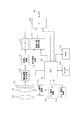
図2は、本実施形態に係る撮像装置100のハードウェア構成の一例を示すブロック図である。図2において、CPU146は、撮像装置100を統括制御する中央演算処理回路である。EEPROM(Electrically Erasable Programmable Read Only Memory)148は、CPU146を動作させるためのソフトウェアプログラムを格納する。RAM149は、各種情報を一時的に保持するメモリである。
FIG. 2 is a block diagram illustrating an example of a hardware configuration of the
パン駆動回路111、チルト駆動回路112、およびズーム駆動回路113は、クライアント装置200から受信されたコマンドをCPU146が解釈することによって生成された制御信号に基づいて駆動する。
The
前玉レンズ122、バリエータレンズ124は撮像光学系を構成する。CPU146からの駆動信号に基づき、バリエータレンズ124が光軸方向に移動する。すなわちバリエータレンズ124の移動に伴い、撮像光学系の焦点距離が変化することにより、ズーム倍率が変化する。
The
撮像素子126は、CMOSなどのイメージセンサである。画像信号処理回路128は、撮像素子126から出力された画像信号(RGB)を輝度色差信号などの画像信号に変換する。符号化回路130は、H.264あるいはH.265などの規格に基づいて変換された画像信号を符号化する。バッファ132は、符号化された画像信号をネットワーク上に送信するために一時的に記憶する。通信回路(以下、I/Fと称する場合がある)134および通信端子136は符号化された画像信号をネットワーク上のクライアント装置200に出力する。動き検出回路138は、画像信号処理回路128から出力された画像信号を既存の技術を用いて解析することにより、画像内の物体の動きを検出する。
The image sensor 126 is an image sensor such as a CMOS. The image
物体位置判定回路140は、動きが検出された領域を物体として判定するか、あるいは動きが検出された領域のうち、顔認識された部分あるいは人体が検出された部分の領域を物体として判定し、その画像内の位置を特定する。本実施の形態ではこの判定された物体を検知物体として説明する。また、検知物体の領域を関心領域としてもよいが、以下では検知物体の外接矩形を関心領域として説明する。
The object
本実施形態では、ユーザによるパン/チルト/ズームの操作を修正することにより、物体位置が撮像画角内に収まるようにパン/チルト/ズーム制御が実行される。すなわち、クライアント装置200からの制御信号に基づいてパン/チルト/ズームが制御されたとき、物体が撮像画角端付近に存在するおそれがある場合には、CPU146は、当該の物体が画角内に入るようにパン/チルト/ズーム動作を微調整する。
In the present embodiment, the pan / tilt / zoom control is executed so that the object position is within the imaging angle of view by correcting the pan / tilt / zoom operation by the user. In other words, when pan / tilt / zoom is controlled based on a control signal from the
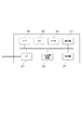
図8は、クライアント装置200のハードウェア構成を示す図である。CPU201は、RAM202およびROM203に格納されているコンピュータプログラムやデータを用いてクライアント装置200全体の制御を行う。
FIG. 8 is a diagram illustrating a hardware configuration of the
RAM202は、ROM203からロードされたコンピュータプログラムやデータ、I/F(インターフェース)207を介して外部から取得したデータなどを一時的に記憶するためのエリアを有する。更に、RAM202は、CPU201が各種の処理を実行する際に用いるワークエリアを有する。即ち、RAM202は、例えば、画像メモリとして割り当てたり、その他の各種のエリアを適宜提供したりすることができる。
The
ROM203には、クライアント装置200の設定データや、コンピュータであるクライアント装置が実行可能なソフトウェアプログラムなどが格納されている。操作部204は、キーボードやマウスなどにより構成されており、クライアント装置200のユーザの操作により、各種の指示をCPU201に対して入力することができる。表示部205は、LCDなどのスクリーンを有し、撮像装置100からの画像およびCPU201による処理結果を表示する。
The
2次記憶装置206は、ハードディスクドライブ装置に代表される、大容量情報記憶装置である。外部記憶装置206には、OS(オペレーティングシステム)や、図2に示した各部の機能をCPU201に実現させるためのコンピュータプログラムが保存されている。更には、外部記憶装置206には、撮像装置100からの画像が保存される。
The
2次記憶装置206に保存されているコンピュータが実行可能なソフトウェアプログラムやデータは、CPU201による制御に従って適宜、RAM202にロードされ、CPU201による処理対象となる。I/F207は、LANやインターネット等のネットワーク、投影装置や表示装置などの他の機器を接続するためのものであり、クライアント装置200は、このI/F207を介して様々な情報を取得したり、送出したりすることができる。
Software programs and data that can be executed by the computer and stored in the
以下に、図3を用いて、クライアント装置200と撮像装置100との間において、パン/チルト/ズームを変更する典型的なBoxZoomコマンドシーケンスを説明する。ここで、トランザクションとは、クライアント装置200から撮像装置100へ送信されるコマンドと、それに対して撮像装置100からクライアント装置200へ返送するレスポンスのペアのことを指している。
Hereinafter, a typical BoxZoom command sequence for changing pan / tilt / zoom between the
トランザクション1201は、GetServiceCapabilitiesコマンドのトランザクションである。GetServiceCapabilitiesコマンドは、撮像装置100がサポートする機能を示す機能情報を返送するように指示するコマンドである。この機能情報は、SetBoxZoomコマンドの情報を含む。クライアント装置200は第1の座標および第2の座標のデータを含むSetBoxZoomコマンドを生成する。この第1の座標および第2の座標は、それぞれ、クライアント装置200の表示部205の画面上で矩形枠を指定する際の開始点(例えば、X1座標)、終了点(例えば、X2座標)である。撮像装置100は、受信したSetBoxZoomコマンドに含まれる第1および第2の座標に基づいて撮像装置100が制御されるべき撮像方向およびズーム倍率の変更値を算出し、算出した変更値に基づいて撮像装置100を駆動する。具体的には、第1および第2の座標の中点つまり表示部205に表示される画像上で指定した矩形の中心座標から表示部205に表示される画像の中心までの距離を算出する。そして、変更前のズーム倍率および算出された距離に基づいて撮像方向の変更量を決定する。さらに、表示される画像のサイズとユーザによって指定された矩形枠のサイズとの比率に基づいて変更すべきズーム倍率を決定する。
The
トランザクション1202は、GetCofigurations コマンドのトランザクションである。GetCofigurationsコマンドを撮像装置に送信することにより、クライアント装置200は、撮像装置100のPTZ(パン、チルト、ズーム)設定の情報を取得する。具体的には、受信したGetCofigurationsコマンドに対して、撮像装置100は、撮像装置100に設定されている全てのPTZ設定のリストをクライアント装置200に返す。このPTZ設定のリストには、複数のPTZ設定を含むことができるとともに、各PTZ設定を識別するためのtoken情報が含まれる。このtoken情報を、本実施形態では、ConfigurationTokenと称する。
トランザクション1203は、GetConfigurationOptions コマンドのトランザクションである。クライアント装置200は、ConfigurationTokenを含ませて、GetConfigurationOptionsコマンドを撮像装置100に送信する。撮像装置100は、ConfigurationToken指定された設定における可能なオプション情報をGetConfigurationOptionsレスポンスに格納してクライアント装置200に送信する。例えば、本実施形態では、上記 GetConfigurationOptions レスポンスは、SetBoxZoomコマンドに設定可能なProfileTokenのリストを含む。クライアント装置200は、ProfileTokenのリストから、所望のProfileTokenを選択して、SetBoxZoomコマンドを発行する。
A
トランザクション1204は、上述したSetBoxZoomコマンドのトランザクションである。このコマンドにより、クライアント装置200は、SetBoxZoomリクエスト情報、ProfileToken情報、第1座標および第2座標を有するSetBoxZoomコマンドを撮像装置100に送信する。SetBoxZoomコマンドを受信した撮像装置100は、ProfileToken、第1座標、および、第2座標をRAM149に記憶するとともに、SetBoxZoomレスポンスをクライアント装置200に送信する。
The
また、撮像装置100は、上述したように、第1座標、及び、第2座標に基づき、撮像装置100が撮像している画像の撮像画角を変更する。すなわち、撮像装置100は、第1座標、及び、第2座標に基づき、パン/チルト/ズーム機構の駆動を行う。
Further, as described above, the
また、本実施形態の撮像装置は、パン、チルト、及び、ズーム機構の駆動を行う際に、物体が画角端付近に存在しているおそれがある場合には、当該の物体が画角内に入るようにパン/チルト/ズーム動作を調整する。 In addition, when the panning, tilting, and zooming mechanisms are driven, the imaging apparatus according to the present embodiment may cause the object to be within the angle of view if the object may exist near the angle of view. Adjust the pan / tilt / zoom operation to enter.
図4(a)は、SetBoxZoomコマンドのデータ構造、図4(b)は、SetBoxZoomレスポンスのデータ構造の一例を示す図である。 FIG. 4A shows an example of the data structure of the SetBoxZoom command, and FIG. 4B shows an example of the data structure of the SetBoxZoom response.
図4(a)において、宛先アドレス3001はSetBoxZoomコマンドの送信先である撮像装置100のアドレス情報が格納される。送信元アドレス3003は、送信元であるクライアント装置200のアドレス情報が格納される。フィールド3005は、リクエスト種別として、SetBoxZoomリクエストであることを示す情報が格納される。フィールド3007はプロファイルトークンフィールドを示す。フィールド3009は開始点座標フィールドであり、フィールド3015は終了点座標フィールドである。開始点座標フィールド3009、および、終了点座標フィールド3015は、それぞれ、X座標フィールドとY座標フィールドを含む。フィールド3011は開始点のX座標フィールド、フィールド3013は開始点のY座標フィールドである。また、フィールド3017は終了点のX座標フィールド、フィールド3019は終了点のY座標フィールドである。
In FIG. 4A, the
一方、図4(b)において、フィールド3021は宛先アドレス、フィールド3023は送信元アドレス、フィールド3025はSertBoxZoomレスポンス・フィールドである。このSetBoxZoomレスポンスでは、フィールド3025は、レスポンスの種別として、このレスポンスがSertBoxZoomレスポンスであることを示す情報が格納される。また、宛先アドレス3021にはSetBoxZoomレスポンスの送信先であるクライアント装置200のアドレス情報が格納され、送信元アドレス3023には送信元である撮像装置100のアドレス情報が格納される。
On the other hand, in FIG. 4B, a
本実施形態では、図4(a)で示される開始点のX座標フィールド3011の値が終了点のX座標フィールド3017の値よりも小さい場合、撮像装置100の撮像光学系の焦点距離を長くする(すなわちズーム倍率の値を大きくする)ように調整される。また、例えば、開始点のX座標値3011が、終了点のX座標値3017よりも大きい場合に、本実施形態に係る撮像装置の撮像光学系の焦点距離を短くする(すなわちズーム倍率の値を小さくする)ように調整される。さらに、例えば、開始点のX座標値3011が、終了点のX座標値3017と同じ値であれば、ズーム倍率の制御を行わずに、当該X座標値に表示される画像部分が画像の中心に位置するように撮像装置100のパン及びチルトが制御される。
In the present embodiment, when the value of the X coordinate
撮像装置100は、SetBoxZoomコマンドに格納された情報に基づいて、パン/チルト/ズームの動作を開始する。上述したように、開始点のX座標フィールド3011の値が、終了点のX座標フィールド3017の値よりも小さい場合には、所謂ズームイン動作(望遠方向のズーム動作)を行う。この際のズーム動作は、開始点座標フィールド3009と終了点座標フィールドで指定される矩形の範囲をズームイン動作後の撮像範囲とするようにパン/チルト/ズームが制御される。また、物体位置判定回路140によって撮像範囲の境界付近(撮像画角上の端位置付近)に物体が検出されている場合には、検出物体が撮像範囲内に位置するようにパン/チルト/ズームの動作が調整される。
The
また、上述したように開始点のX座標フィールド3011の値が、終了点のX座標フィールド3017の値よりも大きい場合には、ズームアウト動作(広角方向のズーム動作)が行われる。この際、本実施形態の撮像装置100は、開始点座標フィールド3009と終了点座標フィールド3015で定義される矩形の範囲がズームアウト動作前の撮像画角(撮像範囲)に対応するようにパン/チルト/ズームが制御される。また、物体位置判定回路140が、撮像範囲の境界付近(撮像画角上の端位置付近)に物体を検出した場合には、検出物体が撮像範囲内に位置するようにパン/チルト/ズームが微調整される。このズームアウトの動作は、開始点座標フィールド3009と終了点座標フィールド3015とのどちらか一方、または両方に、現在の撮影範囲の範囲外であることを示す座標値を格納することで行うことができる。
Further, as described above, when the value of the X coordinate
上述したように、本実施形態では、ズームアウト動作後の撮像範囲は、他の指定方法で決めてもよい。例えば、ズームアウト前の撮像画角内における二点の座標を開始点座標フィールド3009、及び、終了点座標フィールド3015に指定する方法でズームアウトを動作させてもよい。この場合、ズーム倍率は、例えば、撮像範囲の横方向長さ(X方向長さ)に対する、開始点座標フィールド3009と終了点座標フィールド3015で指定される矩形のX方向長さの比を用いる。また、ズーム倍率を、撮像範囲の縦方向長さ(Y方向長さ)に対する、開始点座標フィールド3009と終了点座標フィールド3015で指定される矩形のY方向長さの比を用いて指定してもよい。さらに、ズーム倍率を、撮像範囲の対角方向長さと、開始点座標フィールド3009と終了点座標フィールド3015で指定される矩形の対角方向長さの比で指定してもよい。
As described above, in the present embodiment, the imaging range after the zoom-out operation may be determined by another designation method. For example, zoom-out may be performed by a method of designating the coordinates of two points within the imaging field angle before zoom-out in the start point coordinate
次に図5を用いて、本実施形態で用いる座標系の構成を説明する。図5において、座標系の範囲3502は、撮像装置100の現在の撮像範囲(撮像画角)に対応している。具体的には、クライアント装置200の表示部205における表示画面上に表示される撮像画像の範囲に座標系の範囲3502が表示される。撮像範囲3502は、SetBoxZoomコマンドの座標系の範囲(−1.0≦X≦1.0,−1.0≦Y≦1.0)に対応している。この座標系は、例えば、正規化座標系と呼称される。この正規化座標系では、撮像装置100のパン/チルト/ズーム値に依存せず、X座標値およびY座標値が−1から+1になるように構成される。
Next, the configuration of the coordinate system used in this embodiment will be described with reference to FIG. In FIG. 5, a coordinate
矩形範囲3503は、クライアント装置200において表示された画像上に指定された矩形範囲に対応しており、SetBoxZoomコマンドの開始点座標フィールド3009と終了点座標フィールド3015によって定義される。座標3504はSetBoxZoomコマンドの開始点(X1,Y1)、座標3505はSetBoxZoomコマンドの終了点(X2,Y2)を示している。また、座標3506は指定された矩形範囲の中心点(X3,Y3)を示している。図5に示す例では、開始点のX座標値X1が、終了点のX座標値X2よりも小さいので、ズームイン動作(望遠動作)がなされ、撮像光学系の焦点距離は長くなるように(ズーム倍率が高くなるように)調整される。また、図5に示す例とは反対に、開始点のX座標値X1が、終了点のX座標値X2よりも大きい場合には、ズームアウト動作(広角側の動作)がなされ、撮像光学系の焦点距離は短くなるように(ズーム倍率が小さくなるように)調整される。また矩形の中心点を示す座標3506に対応する画像部分がズーム動作後の中心になるようにパン及びチルトが制御される。
The
ズームアウトの際、クライアント装置200は、開始点座標フィールド3009と終了点座標フィールド3015とのどちらか一方、または両方に、現在の撮影範囲の範囲外の座標値を格納することになる。例えば、クライアント装置200は、開始点X座標フィールド3011、開始点Y座標フィールド3013のどちらか一方、または、両方に、+1よりも大きい値を格納することになる。あるいは、終了点X座標フィールド3017、終了点Y座標フィールド3019のどちらか一方、または、両方に、−1よりも小さい値を格納することになる。すなわち、本実施形態では、ズームアウトの際、開始点座標フィールド3009と終了点座標フィールド3015とで指定される矩形範囲3503が、現在の撮影枠3502より大きい範囲を指定することにより、ズームアウトの比率を指定することができる。具体的には、指定された矩形範囲3503をズーム動作前の撮影範囲に対応する座標範囲とする(すなわち、−1.0≦X≦1.0、−1.0≦Y≦1.0)。この矩形範囲3503の位置に対して相対する撮影範囲3502を示す座標値を開始点X座標フィールド3011、開始点Y座標フィールド3013に格納することになる。
When zooming out, the
本実施の形態では、図5に示すような矩形範囲の境界3503の付近に物体が存在した場合、物体位置判定回路140はCPU146に対して、パン/チルト/ズーム動作の微調整を行わせるための信号を出力する。CPU146は、微調整信号の指示に基づいて、パン/チルト/ズーム動作を調整し、検出された物体がパン/チルト/ズーム動作後の撮像範囲内に入るように制御させる。
In the present embodiment, when an object exists in the vicinity of the
図6は、クライアント装置200において表示部205の表示画面の一例を示す図である。撮像範囲4001は、撮像装置100の撮像範囲(撮像画角)を示しており、この範囲内に現在の撮像画像が表示される。撮像範囲4001は、図5の撮像範囲3502に対応している。矩形範囲4003は、操作部204を用いてユーザが表示部の画面上で指定された2点(開始点4004、終了点4005)によって定義される。この矩形範囲を定義する開始点と終了点とがSetBoxZoomコマンドの開始点座標フィールド3009と終了点座標フィールド3015に格納される情報に対応する。なお、中心点4006は、指定された矩形範囲4003の中心座標である。物体4008は、動き検出回路140において検出された物体であり、矩形4009は検出物体4008の外接矩形であり、関心領域である。また、図6(b)の中心点4011はパン/チルト/ズームの微調整後の画角中心点を示す。
FIG. 6 is a diagram illustrating an example of a display screen of the
図6(a)は、矩形範囲4003の指定に基づいてパン/チルト/ズームが制御される前の撮像画像を示している。図6(a)において、開始点座標4004のX座標値が、終了点座標4005のX座標値よりも小さいので、ズームイン動作(望遠側の動作)が行われる。本実施形態では、指定された矩形範囲4003の中心点4006が、パン/チルト/ズーム動作後の撮像画角中心4011となるように、CPU146は、パン/チルト/ズーム動作を調整するようになっている。
FIG. 6A shows a captured image before pan / tilt / zoom is controlled based on the designation of the
ところが、このズームイン動作をする際、図6(a)においては、検出物体4008が指定された矩形範囲の境界付近に位置している。このままでは検出物体の一部が画角から外れてしまうため、物体位置判定回路140はCPU146に対して、微調整信号を出力する。微調整信号を受信したCPU146は、物体位置判定回路140が併せて出力する検出物体4008に対する外接矩形4009の情報に基づき、撮像装置100のパン/チルト/ズーム動作のうち少なくとも1つを調整して外接矩形4009が撮像画角内に入るように動作させる。
However, when performing this zoom-in operation, in FIG. 6A, the detected
図6(b)は、パン/チルト/ズーム微調整後の撮像画像を示す図である。パン/チルト/ズーム動作前に、指定された矩形範囲の境界付近に位置していた物体4008に対して、関心領域である検知物体4008の外接矩形4009が撮像画角内に入るように、パン/チルト/ズームが微調整されている。
FIG. 6B is a diagram illustrating a captured image after pan / tilt / zoom fine adjustment. Before the pan / tilt / zoom operation, panning is performed so that the circumscribed rectangle 4009 of the
図7は、SetBoxZoomコマンドをクライアント装置200から受信した場合における撮像装置100の動作処理フローチャートである。
FIG. 7 is an operation process flowchart of the
図7において、ステップS5000で本実施形態の動作が開始される。ステップS5005では、SetBoxZoomコマンドのI/F134の受信処理が行われる。そしてステップS5010において、CPU146により、受信したSetBoxZoomコマンドに格納されたパラメータが解析される。解析されるパラメータは、例えば、図4で示されたプロファイルトークンフィールド3007、開始点座標フィールド3009、及び、終了点座標フィールド3015である。ステップS5015において、CPU146は、I/F134を介してSetBoxZoomコマンドに対するレスポンスを送信する。
In FIG. 7, the operation of this embodiment is started in step S5000. In step S5005, reception processing of the I /
ステップS5018において、CPU146は、SetBoxZoomコマンドのパラメータ解析結果を評価する。パラメータが正常である場合、ステップS5020に進む。また、パラメータが異常である場合には、実行不能としてステップS5400に進み処理が終了する。パラメータ異常の例としては、プロファイルトークンフィールド3007の値が、撮像装置100に設定されていない値の場合などである。また、他のパラメータ異常の例としては、開始点座標フィールド3009、または、終了点座標フィールド3015の少なくともどちらか一方の座標値が、撮像装置100がサポートしていない座標の範囲であった場合などである。パラメータが正常である場合、ステップS5015で送信するSetBoxZoomレスポンスは成功(SCCESS)レスポンスであり、パラメータが異常の場合は、SetBoxZoomレスポンスは失敗(FAIL)レスポンスが送信されることになる。
In step S5018, the
パラメータが正常である場合、次のステップS5020に進み、CPU146により、開始点のX座標値X1と終了点のX座標値X2とが比較される。ステップS5020でX1値がX2値よりも小さい場合、ステップS5100に進み、ズームイン動作するための処理が行われる。
If the parameter is normal, the process proceeds to the next step S5020, and the
ステップS5100において、CPU146により、指定された開始点座標と終了点座標とによって定まる矩形範囲のサイズと撮像範囲のサイズに基づいて、ズーム倍率が仮決定される。
In step S5100, the
次のステップS5105において、CPU146により、指定された矩形範囲4003の境界付近に検出物体4008が存在するかどうかが判定される。関心領域である外接矩形4009を定義する4つの座標のうちいずれかの座標が矩形範囲4003の内部に存在し、その他の座標が外部に存在するときに境界付近に検出物体が存在すると判別してもよい。また、検出物体の外接矩形の中心と矩形範囲4003の境界との距離が所定範囲内に存在する場合に境界付近に検出物体が存在すると判別してもよい。
In the next step S5105, the
境界付近に物体が無い場合、ステップS5120に進む。また、指定された矩形範囲の境界付近に検出物体が存在した場合、ステップS5110に進み、CPU146により、仮決定されたズーム倍率が制御されるべき値として決定される。
If there is no object near the boundary, the process advances to step S5120. If a detected object is present near the boundary of the designated rectangular range, the process advances to step S5110, and the
ステップS5110において、CPU146により、ズーム倍率が微調整される。具体的には、検出物体の外接矩形4009を定義する4つの座標の全てが含まれるように矩形範囲4003のサイズを変更する。そして、この変更されたサイズに対応するズーム倍率が最終的なものとして決定される。
In step S5110, the
ステップS5120では、CPU146により、ズーム倍率が決定される。ここで、ステップS5120で決定されるズーム倍率は、ステップS5110において微調整されたズーム倍率に決定される。また、ステップS5105で境界付近に物体が無いと判断された場合には、決定されるズーム倍率は上述のとおり仮決定のズーム倍率と同じになる。
In step S5120, the
次のステップS5125では、CPU146によってパン量、及び、チルト量が算出される。パン/チルト量は、上述したとおり、図6における矩形範囲4003の中心点座標4006と撮像範囲4001の中心との距離に基づき決定される。ステップS5130において、決定されたパン/チルト量、及び、ズーム倍率に基づいて、パン/チルト/ズームが駆動され、次のステップS5400で本実施形態の処理が終了する。
In the next step S5125, the
一方、ステップS5020において、開始点のX座標値X1が終了点のX座標値X2値よりも大きい場合、ステップS5200に進み、上述した方法に基づいてズームアウト動作(広角側の動作)が行われる。 On the other hand, in step S5020, if the X coordinate value X1 of the start point is larger than the X coordinate value X2 value of the end point, the process proceeds to step S5200, and the zoom-out operation (wide-angle side operation) is performed based on the method described above. .
ステップS5200では、CPU146により、矩形範囲4003の中心点座標4006と座標系の中心点との差異に基づいてパン量、チルト量が算出される。さらに、ステップS5205において、指定された開始点座標と終了点座標とから、ズーム倍率が仮決定され、次のステップS5205で、算出されたパン量、チルト量、及び、仮決定されたズーム倍率に基づいて、パン/チルト/ズームのうち少なくとも1つの駆動が実行される。
In step S5200, the
ステップS5210において、パン/チルト/ズーム動作後の撮像画角境界付近に、物体が検出されるか否かが判定される。具体的には検出物体の外接矩形が撮像範囲(撮像画角)の境界に接しているかどうか判断する。つまり、図5に示す座標系で検出物体の外接矩形がX=±1、あるいはy=±1に接しているかどうか判断する。 In step S5210, it is determined whether or not an object is detected near the imaging field angle boundary after the pan / tilt / zoom operation. Specifically, it is determined whether or not the circumscribed rectangle of the detected object is in contact with the boundary of the imaging range (imaging field angle). That is, it is determined whether or not the circumscribed rectangle of the detected object is in contact with X = ± 1 or y = ± 1 in the coordinate system shown in FIG.
画角境界付近に物体が検出されていない場合、ステップS5400に進み、処理が終了する。また、画角境界付近に物体が検出された場合には、ステップS5215に進み、ズーム倍率の再設定がなされる。 If no object is detected near the view angle boundary, the process advances to step S5400, and the process ends. If an object is detected near the view angle boundary, the process advances to step S5215 to reset the zoom magnification.
ステップS5220では、再設定されたズーム倍率の値にズームが再び制御される。次のステップS5225では、ズームが制御された後に撮像範囲内に検出物体が収まったかどうかCPU146により判定される。ステップS5225で、物体が画角内に入っていない場合、すなわち検出物体の外接矩形(関心領域)が撮像範囲の境界と接している場合、ステップS5215のズーム倍率の再設定とステップS5220のズーム再駆動が実行される。
In step S5220, zooming is controlled again to the reset zoom magnification value. In the next step S5225, the
ステップS5215、ステップS5220、及び、ステップS5225のループにより、本実施形態では、ズームアウト動作時に画角境界付近に位置する物体を画角内に入るように微調整できる。ステップS5225で、物体が画角内に入ったと判断されると、ステップS5400で本実施形態の処理が終了する。 According to the loop of step S5215, step S5220, and step S5225, in this embodiment, an object located near the view angle boundary can be finely adjusted so as to fall within the view angle during the zoom-out operation. If it is determined in step S5225 that the object has entered the angle of view, the processing of this embodiment ends in step S5400.
ステップS5020において、開始点のX座標値X1と終了点のX座標値X2とが同じ値の場合(あるいはX1とX2との差が所定値以下の場合)、ステップS5300に進み、CPU146により所謂センタリング動作が行われる。ステップS5300では、SetBoxZoomコマンドで指定されたX座標が、パン/チルト動作後(撮影方向の変更後)の撮像範囲(撮像画角)の中心点となるように、CPU146によりパン量が算出される。またチルト量に関しては、開始点のY座標値Y1と終了点のY座標値Y2との中点が撮像画角の中心点となるように(あるいは中心点付近となるように)チルト量がCPU146により算出される。
In step S5020, if the X coordinate value X1 of the start point is the same as the X coordinate value X2 of the end point (or if the difference between X1 and X2 is equal to or smaller than a predetermined value), the process proceeds to step S5300, and the
ステップS5305において、パン/チルトが駆動されると、ステップS5210に進み、パン/チルト動作後の画角境界付近に物体が検出されるか否かが判定される。ステップS5210で、物体が検出された場合には、続くステップS5215、ステップS5220、ステップS5225で、上述したように検出物体が画角内に入るようにズームが再駆動される。一方、ステップS5210において、パン/チルト動作後の画角境界付近に物体が検出されなかった場合には、ステップS5400に進み処理が終了する。 If pan / tilt is driven in step S5305, the process advances to step S5210 to determine whether or not an object is detected near the view angle boundary after the pan / tilt operation. If an object is detected in step S5210, the zoom is re-driven in subsequent steps S5215, S5220, and S5225 so that the detected object falls within the angle of view as described above. On the other hand, if no object is detected in the vicinity of the view angle boundary after the pan / tilt operation in step S5210, the process proceeds to step S5400 and the process ends.
なお、上述した図7のフローチャートの処理では、検出物体を撮影範囲に含めるためにズーム倍率を制御していたが、撮像方向を変更する処理によっても可能である。例えば、ズームインの動作において、ステップS5110では、ズーム倍率値の計算に代えて、検出物体の外接矩形4009のX方向およびY方向の長さがそれぞれ矩形範囲4003のX方向およびY方向の長さより小さいとCPU146によって判定されたとする。この場合、撮像方向を変更(パン/チルト)するだけで検出物体を撮像範囲に含ませることができる。このとき、矩形範囲4003に対して検出物体4009の外接矩形のはみ出し部分の長さをX座標方向およびY座標方向に関して求め、その長さに基づいて撮像方向の変更量を決定すればよい。また、例えば、ズームアウトの動作において、ステップS5215では、CPU146により、ズーム倍率値の設定に代えて、検出物体の外接矩形と撮像範囲の境界とが接している部分の方向に撮像方向を所定量変更させてもよい。そして、外接矩形が撮像範囲内に含められ、撮像範囲の境界と接しなくなったときに処理を終了してもよい。
In the process of the flowchart of FIG. 7 described above, the zoom magnification is controlled in order to include the detected object in the shooting range, but the process can be performed by changing the imaging direction. For example, in the zoom-in operation, in step S5110, instead of calculating the zoom magnification value, the lengths of the circumscribed rectangle 4009 of the detected object in the X direction and Y direction are smaller than the lengths of the
また、本実施形態では、物体検出のルールを設定可能かどうかの能力情報を撮像装置100に予めクライアント装置200から問い合わせて、その結果に基づいて動作を制御するように構成してもよい。この場合、本実施形態では、上記物体検出のルールに合致した被写体が境界付近に検出された場合、パン/チルト/ズーム動作が微調整される。また、予めユーザが関心領域を設定しておきその関心領域の位置情報を撮像装置100に格納しておき、この設定された関心領域が境界付近に検出された場合に、当該設定領域を画角内に入るように制御する構成でもよい。
Further, in the present embodiment, it may be configured such that capability information indicating whether or not an object detection rule can be set is inquired from the
また、本実施形態の撮像装置100に対しては、GetConfigurationOptions コマンドを用いて、SetBoxZoomコマンドを実行可能かどうかの能力情報を問い合わせることが可能である。その際、撮像装置100は、SetBoxZoomコマンドが実行可能であることを示す情報をレスポンスに含ませて送信する。これにより、クライアント装置200が、撮像装置100に対して以前に接続を行ったことのない場合であっても、GetConfigurationOptions コマンドに対するレスポンスに基づいて上記動作を行わせることが可能である。
In addition, the
(その他の実施例)
本発明は、上述の実施形態の1以上の機能を実現するプログラムを、ネットワーク又は記憶媒体を介してシステム又は装置に供給し、そのシステム又は装置のコンピュータにおける1つ以上のプロセッサーがプログラムを読出し実行する処理でも実現可能である。例えば、画像信号処理回路128、符号化回路130、動き検出回路138、および物体位置検出回路140の機能がプログラムとして撮像装置100に供給されてもよい。また、1以上の機能を実現する回路(例えば、ASIC)によっても実現可能である。
(Other examples)
The present invention supplies a program that realizes one or more functions of the above-described embodiments to a system or apparatus via a network or a storage medium, and one or more processors in a computer of the system or apparatus read and execute the program This process can be realized. For example, the functions of the image
100 撮像装置
200 クライアント装置
300 ネットワーク
134 通信回路
140 物体位置判定回路
142 パン駆動回路
143 チルト駆動回路
144 ズーム駆動回路
146 中央演算処理回路
DESCRIPTION OF
Claims (9)
クライアント装置から第一の座標値と第二の座標値とを含む第一コマンドを受信する受信手段と、
撮像装置の撮像範囲を決定するための制御手段と、
前記受信手段によって受信されたコマンドに含まれる第一の座標値と第二の座標値に対応する撮像範囲の境界付近に関心領域が存在するかどうかを判断する判断手段と、を有し、
前記判断手段によって前記撮像範囲の境界に関心領域が存在すると判断された場合、
前記制御手段は、前記関心領域が前記撮像範囲内に含まれるように調整されたズーム倍率、および、前記第一の座標値と前記第二の座標値との中心座標と前記撮像範囲の中心との距離に基づいて決定されたパン量およびチルト量に基づいて、撮像されるべき撮像範囲を、前記第一の座標値と第二の座標値に対応する撮像範囲から、前記関心領域を含む撮像範囲へと調整し、
前記判断手段によって前記撮像範囲の境界に関心領域が存在しないと判断された場合、前記制御手段は、撮像されるべき撮像範囲を、前記第一の座標値と第二の座標値に対応する撮像範囲とすることを特徴とする撮像装置。 Changing means for changing the imaging direction of the imaging device;
Receiving means for receiving a first command including a first coordinate value and a second coordinate value from a client device;
Control means for determining the imaging range of the imaging device;
Determining means for determining whether or not there is a region of interest near the boundary of the imaging range corresponding to the first coordinate value and the second coordinate value included in the command received by the receiving means;
When it is determined by the determination means that a region of interest exists at the boundary of the imaging range,
The control means includes a zoom magnification adjusted so that the region of interest is included in the imaging range, a center coordinate between the first coordinate value and the second coordinate value, and a center of the imaging range. Based on the pan amount and the tilt amount determined based on the distance, the imaging range to be imaged includes the region of interest from the imaging range corresponding to the first coordinate value and the second coordinate value. Adjust to range,
When the determination unit determines that there is no region of interest at the boundary of the imaging range, the control unit sets the imaging range to be imaged to the imaging corresponding to the first coordinate value and the second coordinate value. An imaging device characterized by being in a range.
前記焦点距離の変更手段は、
前記第一コマンドの前記第一の座標値の少なくとも一部が前記第二の座標値の少なくとも一部よりも大きい場合に焦点距離を長く変更し、
前記第一コマンドの前記第一の座標値の少なくとも一部が前記第二の座標値の少なくとも一部よりも小さい場合に焦点距離を短く変更し、
前記撮像方向の変更手段は、
前記第一コマンドに含まれる前記第一の座標値と前記第二の座標値との差が所定の値よりも小さい場合に当該座標値が撮像範囲の中心点付近となるように撮像方向を変更し、前記撮像方向の変更手段は、
前記関心領域が撮像範囲内に位置するように前記撮像方向を変更する、請求項1に記載の撮像装置。 A focal length changing means for changing the focal length,
The focal length changing means includes:
Changing the focal length longer if at least a portion of the first coordinate value of the first command is greater than at least a portion of the second coordinate value;
Changing the focal length to be shorter when at least part of the first coordinate value of the first command is smaller than at least part of the second coordinate value;
The imaging direction changing means includes:
When the difference between the first coordinate value and the second coordinate value included in the first command is smaller than a predetermined value, the imaging direction is changed so that the coordinate value is near the center point of the imaging range. And, the imaging direction changing means is
The imaging device according to claim 1, wherein the imaging direction is changed so that the region of interest is located within the imaging range.
前記第一コマンドに基づき撮像光学系の焦点距離を短く変更する場合に、前記関心領域が撮像範囲内に位置するように前記撮像光学系の焦点距離を変更する、請求項2に記載の撮像装置。 The focal length changing means includes:
The imaging apparatus according to claim 2, wherein when the focal length of the imaging optical system is changed to be short based on the first command, the focal length of the imaging optical system is changed so that the region of interest is located within the imaging range. .
クライアント装置から第一の座標値と第二の座標値とを含む第一コマンドを受信する受信ステップと、
前記受信ステップによって受信されたコマンドに含まれる第一の座標値と第二の座標値に対応する撮像範囲の境界付近に関心領域が存在するかどうかを判断する判断ステップと、
前記判断ステップにおいて前記撮像範囲の境界に関心領域が存在すると判断された場合、前記関心領域が前記撮像範囲内に含まれるように調整されたズーム倍率、および、前記第一の座標値と前記第二の座標値との中心座標と前記撮像範囲の中心との距離に基づいて決定されたパン量およびチルト量に基づいて、撮像されるべき撮像範囲を、前記第一の座標値と第二の座標値に対応する撮像範囲から、前記関心領域を含む撮像範囲へと調整し、前記判断ステップにおいて前記撮像範囲の境界に関心領域が存在しないと判断された場合、撮像されるべき撮像範囲を、前記第一の座標値と第二の座標値に対応する撮像範囲に制御する制御ステップと、を有する制御方法。 A control method for controlling an imaging device having changing means for changing an imaging direction of the imaging device,
A receiving step of receiving a first command including a first coordinate value and a second coordinate value from the client device;
A determination step of determining whether or not there is a region of interest near the boundary of the imaging range corresponding to the first coordinate value and the second coordinate value included in the command received by the reception step;
When it is determined in the determination step that a region of interest exists at the boundary of the imaging range, the zoom magnification adjusted so that the region of interest is included in the imaging range, the first coordinate value, and the first coordinate value Based on the pan amount and the tilt amount determined based on the distance between the center coordinate of the second coordinate value and the center of the imaging range, the imaging range to be imaged is determined based on the first coordinate value and the second coordinate value. When the imaging range corresponding to the coordinate value is adjusted to the imaging range including the region of interest, and it is determined in the determination step that there is no region of interest at the boundary of the imaging range, the imaging range to be imaged is control method and a control step of controlling the imaging range corresponding to the first coordinate value and second coordinate values.
Priority Applications (2)
| Application Number | Priority Date | Filing Date | Title |
|---|---|---|---|
| JP2014233793A JP6566626B2 (en) | 2014-11-18 | 2014-11-18 | Imaging device |
| US14/935,303 US9955081B2 (en) | 2014-11-18 | 2015-11-06 | Imaging apparatus capable of adjusting imaging range to include target region, control method of imaging apparatus, and storage medium storing program therefor |
Applications Claiming Priority (1)
| Application Number | Priority Date | Filing Date | Title |
|---|---|---|---|
| JP2014233793A JP6566626B2 (en) | 2014-11-18 | 2014-11-18 | Imaging device |
Publications (3)
| Publication Number | Publication Date |
|---|---|
| JP2016100636A JP2016100636A (en) | 2016-05-30 |
| JP2016100636A5 JP2016100636A5 (en) | 2017-11-30 |
| JP6566626B2 true JP6566626B2 (en) | 2019-08-28 |
Family
ID=55962872
Family Applications (1)
| Application Number | Title | Priority Date | Filing Date |
|---|---|---|---|
| JP2014233793A Active JP6566626B2 (en) | 2014-11-18 | 2014-11-18 | Imaging device |
Country Status (2)
| Country | Link |
|---|---|
| US (1) | US9955081B2 (en) |
| JP (1) | JP6566626B2 (en) |
Families Citing this family (7)
| Publication number | Priority date | Publication date | Assignee | Title |
|---|---|---|---|---|
| JP6968610B2 (en) * | 2017-08-01 | 2021-11-17 | キヤノン株式会社 | Imaging equipment, information processing methods and programs |
| JP7222683B2 (en) * | 2018-12-06 | 2023-02-15 | キヤノン株式会社 | IMAGING DEVICE AND CONTROL METHOD THEREOF, PROGRAM, STORAGE MEDIUM |
| JPWO2021049473A1 (en) | 2019-09-09 | 2021-03-18 | ||
| JP7451122B2 (en) * | 2019-09-27 | 2024-03-18 | キヤノン株式会社 | Imaging control device, imaging device, and imaging control method |
| JP7383438B2 (en) | 2019-09-27 | 2023-11-20 | キヤノン株式会社 | Imaging control device, imaging device, and imaging control method |
| JP2022062543A (en) * | 2020-10-08 | 2022-04-20 | キヤノン株式会社 | Imaging apparatus, method for controlling imaging apparatus, and program |
| CN116206250A (en) * | 2021-11-30 | 2023-06-02 | 中兴通讯股份有限公司 | Method and device for detecting human body boundary crossing and computer readable storage medium |
Family Cites Families (18)
| Publication number | Priority date | Publication date | Assignee | Title |
|---|---|---|---|---|
| JP4109739B2 (en) * | 1998-01-19 | 2008-07-02 | キヤノン株式会社 | CAMERA CONTROL DEVICE, CAMERA CONTROL SYSTEM, CAMERA CONTROL DEVICE CONTROL METHOD, AND STORAGE MEDIUM |
| JP2001145094A (en) * | 1999-11-12 | 2001-05-25 | Canon Inc | Camera control system and method, and storage medium having its operation processing program stored therein |
| JP3808742B2 (en) * | 2000-10-06 | 2006-08-16 | 富士写真フイルム株式会社 | Pseudo zoom camera |
| JP2004157869A (en) | 2002-11-07 | 2004-06-03 | Canon Inc | Mobile terminal |
| JP4489608B2 (en) * | 2004-03-31 | 2010-06-23 | 富士フイルム株式会社 | DIGITAL STILL CAMERA, IMAGE REPRODUCTION DEVICE, FACE IMAGE DISPLAY DEVICE, AND CONTROL METHOD THEREOF |
| JP2006222617A (en) * | 2005-02-09 | 2006-08-24 | Canon Inc | Remote photography system, remote display controller, and remote photographic device |
| JP4623299B2 (en) * | 2005-12-13 | 2011-02-02 | 富士フイルム株式会社 | Imaging apparatus and imaging method |
| CN101785294B (en) * | 2007-08-27 | 2013-07-10 | 索尼公司 | Imaging device and imaging method |
| JP2011124614A (en) * | 2009-12-08 | 2011-06-23 | Panasonic Corp | Subject tracking device and subject tracking method |
| JP5620142B2 (en) * | 2010-04-28 | 2014-11-05 | オリンパスイメージング株式会社 | Imaging apparatus and imaging method |
| JP5643552B2 (en) * | 2010-06-28 | 2014-12-17 | キヤノン株式会社 | Imaging device |
| JP5865584B2 (en) * | 2010-12-07 | 2016-02-17 | 株式会社日立国際電気 | Specific person detection system and detection method |
| JP5455961B2 (en) * | 2011-04-04 | 2014-03-26 | キヤノン株式会社 | Imaging apparatus and control method thereof |
| JP2013093681A (en) * | 2011-10-25 | 2013-05-16 | Hitachi Ltd | Monitoring camera device and monitoring camera system |
| KR101811717B1 (en) * | 2011-11-14 | 2018-01-25 | 삼성전자주식회사 | Zoom control method and apparatus, and digital photographing apparatus |
| US9413941B2 (en) * | 2011-12-20 | 2016-08-09 | Motorola Solutions, Inc. | Methods and apparatus to compensate for overshoot of a desired field of vision by a remotely-controlled image capture device |
| JP5807565B2 (en) * | 2012-01-27 | 2015-11-10 | 株式会社Jvcケンウッド | Imaging apparatus and control method thereof |
| JP5955171B2 (en) * | 2012-09-11 | 2016-07-20 | キヤノン株式会社 | TRANSMISSION DEVICE, RECEPTION DEVICE, TRANSMISSION METHOD, RECEPTION METHOD, AND PROGRAM |
-
2014
- 2014-11-18 JP JP2014233793A patent/JP6566626B2/en active Active
-
2015
- 2015-11-06 US US14/935,303 patent/US9955081B2/en active Active
Also Published As
| Publication number | Publication date |
|---|---|
| US9955081B2 (en) | 2018-04-24 |
| JP2016100636A (en) | 2016-05-30 |
| US20160142640A1 (en) | 2016-05-19 |
Similar Documents
| Publication | Publication Date | Title |
|---|---|---|
| JP6566626B2 (en) | Imaging device | |
| US11750939B2 (en) | Imaging apparatus, imaging control method, and storage medium | |
| CN112217998B (en) | Imaging device, information processing device, control method thereof, and storage medium | |
| US10104279B2 (en) | Control apparatus, method of controlling the same, and storage medium | |
| JP5591006B2 (en) | Control device for automatic tracking camera system and automatic tracking camera system having the same | |
| US11159711B2 (en) | Image-capturing apparatus | |
| JP2008011497A (en) | Camera apparatus | |
| JP7197981B2 (en) | Camera, terminal device, camera control method, terminal device control method, and program | |
| CN110351475B (en) | Image pickup system, information processing apparatus, control method therefor, and storage medium | |
| JP6608196B2 (en) | Information processing apparatus and information processing method | |
| CN109104562B (en) | Information processing apparatus, information processing method, and recording medium | |
| JP6231757B2 (en) | Imaging apparatus, information processing apparatus, control method therefor, and program | |
| JP2014146979A (en) | Monitor camera system, imaging apparatus, and imaging method | |
| JP2014039166A (en) | Controller of automatic tracking camera and automatic tracking camera equipped with the same | |
| JP2021040249A (en) | Client device, imaging apparatus, and control method of the same | |
| JP6702675B2 (en) | IMAGING DEVICE, IMAGING DEVICE CONTROL METHOD, AND PROGRAM | |
| JP2016115966A (en) | Display system, image display control method, and program | |
| KR102150704B1 (en) | Apparatus and method for processing image | |
| US11997389B2 (en) | Control apparatus, method, and storage medium | |
| US11516390B2 (en) | Imaging apparatus and non-transitory storage medium | |
| US11943528B2 (en) | Information processing apparatus, information processing method, and program | |
| US11516404B2 (en) | Control apparatus and control method | |
| EP3843378A1 (en) | Image processing apparatus, image capturing apparatus and image processing method | |
| US20230188856A1 (en) | Control apparatus, method, and storage medium | |
| US20220272274A1 (en) | Imaging device, storage medium, and method of controlling imaging device |
Legal Events
| Date | Code | Title | Description |
|---|---|---|---|
| A521 | Request for written amendment filed |
Free format text: JAPANESE INTERMEDIATE CODE: A523 Effective date: 20171018 |
|
| A621 | Written request for application examination |
Free format text: JAPANESE INTERMEDIATE CODE: A621 Effective date: 20171018 |
|
| A977 | Report on retrieval |
Free format text: JAPANESE INTERMEDIATE CODE: A971007 Effective date: 20180719 |
|
| A131 | Notification of reasons for refusal |
Free format text: JAPANESE INTERMEDIATE CODE: A131 Effective date: 20180724 |
|
| A521 | Request for written amendment filed |
Free format text: JAPANESE INTERMEDIATE CODE: A523 Effective date: 20180925 |
|
| A131 | Notification of reasons for refusal |
Free format text: JAPANESE INTERMEDIATE CODE: A131 Effective date: 20181023 |
|
| A521 | Request for written amendment filed |
Free format text: JAPANESE INTERMEDIATE CODE: A523 Effective date: 20181221 |
|
| A131 | Notification of reasons for refusal |
Free format text: JAPANESE INTERMEDIATE CODE: A131 Effective date: 20190205 |
|
| A521 | Request for written amendment filed |
Free format text: JAPANESE INTERMEDIATE CODE: A523 Effective date: 20190405 |
|
| TRDD | Decision of grant or rejection written | ||
| A01 | Written decision to grant a patent or to grant a registration (utility model) |
Free format text: JAPANESE INTERMEDIATE CODE: A01 Effective date: 20190702 |
|
| A61 | First payment of annual fees (during grant procedure) |
Free format text: JAPANESE INTERMEDIATE CODE: A61 Effective date: 20190730 |
|
| R151 | Written notification of patent or utility model registration |
Ref document number: 6566626 Country of ref document: JP Free format text: JAPANESE INTERMEDIATE CODE: R151 |