JP6562893B2 - Parameter estimation device, air conditioning system evaluation device, parameter estimation method and program - Google Patents
Parameter estimation device, air conditioning system evaluation device, parameter estimation method and program Download PDFInfo
- Publication number
- JP6562893B2 JP6562893B2 JP2016224282A JP2016224282A JP6562893B2 JP 6562893 B2 JP6562893 B2 JP 6562893B2 JP 2016224282 A JP2016224282 A JP 2016224282A JP 2016224282 A JP2016224282 A JP 2016224282A JP 6562893 B2 JP6562893 B2 JP 6562893B2
- Authority
- JP
- Japan
- Prior art keywords
- model
- parameter
- simulation
- air conditioning
- estimated value
- Prior art date
- Legal status (The legal status is an assumption and is not a legal conclusion. Google has not performed a legal analysis and makes no representation as to the accuracy of the status listed.)
- Expired - Fee Related
Links
Images


Classifications
-
- G—PHYSICS
- G06—COMPUTING; CALCULATING OR COUNTING
- G06F—ELECTRIC DIGITAL DATA PROCESSING
- G06F30/00—Computer-aided design [CAD]
- G06F30/30—Circuit design
- G06F30/36—Circuit design at the analogue level
- G06F30/367—Design verification, e.g. using simulation, simulation program with integrated circuit emphasis [SPICE], direct methods or relaxation methods
-
- F—MECHANICAL ENGINEERING; LIGHTING; HEATING; WEAPONS; BLASTING
- F24—HEATING; RANGES; VENTILATING
- F24F—AIR-CONDITIONING; AIR-HUMIDIFICATION; VENTILATION; USE OF AIR CURRENTS FOR SCREENING
- F24F11/00—Control or safety arrangements
- F24F11/30—Control or safety arrangements for purposes related to the operation of the system, e.g. for safety or monitoring
- F24F11/46—Improving electric energy efficiency or saving
-
- G—PHYSICS
- G06—COMPUTING; CALCULATING OR COUNTING
- G06F—ELECTRIC DIGITAL DATA PROCESSING
- G06F30/00—Computer-aided design [CAD]
- G06F30/10—Geometric CAD
- G06F30/13—Architectural design, e.g. computer-aided architectural design [CAAD] related to design of buildings, bridges, landscapes, production plants or roads
-
- G—PHYSICS
- G06—COMPUTING; CALCULATING OR COUNTING
- G06F—ELECTRIC DIGITAL DATA PROCESSING
- G06F30/00—Computer-aided design [CAD]
- G06F30/20—Design optimisation, verification or simulation
-
- F—MECHANICAL ENGINEERING; LIGHTING; HEATING; WEAPONS; BLASTING
- F24—HEATING; RANGES; VENTILATING
- F24F—AIR-CONDITIONING; AIR-HUMIDIFICATION; VENTILATION; USE OF AIR CURRENTS FOR SCREENING
- F24F2110/00—Control inputs relating to air properties
-
- F—MECHANICAL ENGINEERING; LIGHTING; HEATING; WEAPONS; BLASTING
- F25—REFRIGERATION OR COOLING; COMBINED HEATING AND REFRIGERATION SYSTEMS; HEAT PUMP SYSTEMS; MANUFACTURE OR STORAGE OF ICE; LIQUEFACTION SOLIDIFICATION OF GASES
- F25B—REFRIGERATION MACHINES, PLANTS OR SYSTEMS; COMBINED HEATING AND REFRIGERATION SYSTEMS; HEAT PUMP SYSTEMS
- F25B2500/00—Problems to be solved
- F25B2500/19—Calculation of parameters
Landscapes
- Engineering & Computer Science (AREA)
- Physics & Mathematics (AREA)
- Computer Hardware Design (AREA)
- Theoretical Computer Science (AREA)
- Geometry (AREA)
- General Engineering & Computer Science (AREA)
- General Physics & Mathematics (AREA)
- Evolutionary Computation (AREA)
- Combustion & Propulsion (AREA)
- Chemical & Material Sciences (AREA)
- Mechanical Engineering (AREA)
- Architecture (AREA)
- Civil Engineering (AREA)
- Structural Engineering (AREA)
- Computational Mathematics (AREA)
- Mathematical Analysis (AREA)
- Mathematical Optimization (AREA)
- Pure & Applied Mathematics (AREA)
- Microelectronics & Electronic Packaging (AREA)
- Air Conditioning Control Device (AREA)
Description
本発明の実施形態は、パラメータ推定装置、空調システム評価装置、パラメータ推定方法およびプログラムに関する。 Embodiments described herein relate generally to a parameter estimation device, an air conditioning system evaluation device, a parameter estimation method, and a program.
建物の省エネルギ化などの取り組みのために、建物が備える空調設備の更新または運用変更について、シミュレーションにより比較評価する方法が知られている。シミュレーションを高精度に行うためには、建物において実際に計測された様々な計測データに基づいて、シミュレーションモデルに含まれる多数のパラメータを同定する必要がある。 In order to save energy in buildings and the like, there is known a method for comparative evaluation by simulation of renewal or operation change of air conditioning equipment provided in a building. In order to perform the simulation with high accuracy, it is necessary to identify many parameters included in the simulation model based on various measurement data actually measured in the building.
パラメータの数が多いと、パラメータの同定に必要な繰り返し計算の回数が増加し、同定に要する時間が増加するという問題がある。この問題を回避するために、パラメータの数を削減する手法が取られている。例えば、計測データに対する重回帰分析によって設備に影響しないパラメータを特定することにより、パラメータ数を削減する手法が知られている。また、パラメータに影響を与える分類条件ごとに計測データを分類してからパラメータ同定をすることによってパラメータ数を削減する方法が知られている。 When the number of parameters is large, the number of repeated calculations necessary for parameter identification increases, and there is a problem that the time required for identification increases. In order to avoid this problem, a method of reducing the number of parameters is taken. For example, a technique is known in which the number of parameters is reduced by specifying parameters that do not affect equipment by multiple regression analysis on measurement data. There is also known a method of reducing the number of parameters by classifying measurement data after classifying measurement data for each classification condition affecting parameters.
しかしながら、条件によらず一定であるはずのパラメータ、例えば壁面の熱の伝わりやすさに関する係数など、であっても、当該パラメータに分類条件ごとに個別の値が同定されてしまい、シミュレーションの精度が低くなるという問題がある。 However, even for parameters that should be constant regardless of conditions, such as coefficients related to the ease of heat transfer on the wall surface, individual values are identified for each classification condition in the parameters, and simulation accuracy is reduced. There is a problem of being lowered.
本発明の一実施形態は、建物の空調システムを評価するためのシミュレーションモデルの複数のパラメータに対して、適切とされる値を推定する。 One embodiment of the present invention estimates appropriate values for a plurality of parameters of a simulation model for evaluating a building air conditioning system.
本発明の一実施形態のパラメータ推定装置は、モデル簡略化部と、パラメータ推定値算出部とを備える。モデル簡略化部は、計測データセットと、簡略化可能条件とに基づき、シミュレーションモデルを簡略化することにより、簡略化モデルを生成する。パラメータ推定値算出部は、簡略化モデルと、簡略化モデルに対応する計測データセットとに基づき、簡略化モデルのパラメータに対する推定値を算出する。また、パラメータ推定値算出部は、第1の計測データセットに基づく第1の簡略化モデルの第1のパラメータに対する第1の推定値を算出した後は、第2の計測データセットに基づく第2の簡略化モデルの第1のパラメータに対しては、第1の推定値を適用する。 A parameter estimation device according to an embodiment of the present invention includes a model simplification unit and a parameter estimation value calculation unit. The model simplification unit generates a simplified model by simplifying the simulation model based on the measurement data set and simplification possible conditions. The parameter estimated value calculation unit calculates estimated values for the parameters of the simplified model based on the simplified model and the measurement data set corresponding to the simplified model. The parameter estimated value calculation unit calculates the first estimated value for the first parameter of the first simplified model based on the first measurement data set, and then calculates the second estimated data based on the second measurement data set. The first estimated value is applied to the first parameter of the simplified model.
以下、図面を参照しながら、本発明の実施形態について説明する。 Hereinafter, embodiments of the present invention will be described with reference to the drawings.
(第1の実施形態)
図1は、第1の実施形態に係る空調システム評価装置の概略構成の一例を示すブロック図である。図1に示された空調システム評価装置1は、入力インタフェース(入力IF)11と、記憶部12と、モデル生成部13と、モデル簡略化部14と、パラメータ推定値算出部15と、シミュレーション部16と、出力インタフェース(出力IF)17と、を備える。
(First embodiment)
FIG. 1 is a block diagram illustrating an example of a schematic configuration of the air conditioning system evaluation apparatus according to the first embodiment. An air conditioning
なお、図1のブロックを結びつける線(リンク)は、本実施形態における主要なデータの送受を表しているが、リンクがないブロック同士間でもデータの送受が行われてもよい。例えば、入力インタフェース11はモデル生成部13だけでなく、他の構成要素にデータを渡してもよい。出力インタフェース17も、シミュレーション部16だけでなく、他の構成要素からデータを受け取ってもよい。
A line (link) connecting the blocks in FIG. 1 represents transmission / reception of main data in the present embodiment, but data transmission / reception may be performed between blocks without links. For example, the
空調システム評価装置1は、建物の空調システムを評価する。なお、建物の空調システムは、建物に実際に設置されているものでもよいし、設置が想定されるものでもよい。評価項目は、空調システムの性能、消費エネルギといったものが考えられる。空調システム評価装置1は、空調システムを評価するために、空調システムに係るシミュレーションモデルに対して、シミュレーションを行う。その際、空調システム評価装置1は、シミュレーションモデルを生成し、シミュレーションモデルの簡略化を行い、シミュレーションモデルの複数のパラメータに対して推定値を算出する。
The air conditioning
図2は、第1の実施形態に係る空調システム評価装置の全体処理の概略フローチャートの一例を示す図である。入力インタフェース11が情報を受け付け(S101)、モデル生成部13が、入力インタフェース11が受け付けた情報などに基づき、シミュレーションモデルを生成する(S102)。生成されたシミュレーションモデルは、モデル簡略化部14により簡略化され、簡略化モデルが生成される(S103)。そして、パラメータ推定値算出部15が、簡略化モデルのパラメータの推定値を算出する(S104)。シミュレーション部16は、算出された推定値に基づき、シミュレーションモデルに対するシミュレーションを実行し(S105)、出力インタフェース17がシミュレーション結果などの所望の情報を出力する(S106)。以上が、概略処理のフローである。処理の詳細は、空調システム評価装置1の構成要素とともに後述する。
FIG. 2 is a diagram illustrating an example of a schematic flowchart of the overall processing of the air conditioning system evaluation apparatus according to the first embodiment. The
なお、空調システム評価装置1は、シミュレーションモデルのパラメータの推定値を算出するパラメータ推定装置としても用いることができる。パラメータ推定装置の場合、例えば、上述のフローにおいて、S105の処理が行われずに、S106の処理において、算出されたパラメータの推定値が出力されてもよい。また、出力されたパラメータの推定値に対しユーザが修整を行い、ユーザにより修整された値に基づいて、S105のシミュレーションが行われてもよい。
The air conditioning
空調システム評価装置1の構成要素について説明する。
入力インタフェース11は、シミュレーションを行う際に、ユーザ、外部装置等から情報を受け付ける。本実施形態では、入力インタフェース11は、評価対象の空調システムを設置する建物の概要に関する情報を受け付けることを想定する。以降、当該情報を建物情報と記載する。建物情報は、具体的には、建物の所在地域、用途、面積、階数、築年数、構造、壁面材料の少なくともいずれかの情報を含む。また、建物情報は、gbxml形式などで表記されたBIM(Builging Information Model)などの詳細な設計情報であってもよい。
The components of the air conditioning
The
図3は、建物情報を入力するためのインタフェースの一例を示す図である。図3には、建物情報を入力するためのインタフェースの一例である建物情報入力インタフェース2が示されている。例えば、ユーザが建物情報を入力する際に、入力インタフェース11は、図3に示す建物情報入力インタフェース2を、有線または無線で接続されたディスプレイ等に表示する。建物情報入力インタフェース2の左上部分に示されたBIM読み込み領域21は、BIMなどの詳細な設計情報を入力する領域である。左中ごろから左下の部分に示された概要指定領域22は、建物の概要を入力するための領域である。図3では、用いられる概要項目として、階数、床面積、形状・方角、用途、所在地が示されている。これらのいずれかを指定することで、建物情報が入力される。建物情報の入力後、右部分に示された画像表示領域23に、入力された建物情報に基づく建物を画像で表示してもよい。
FIG. 3 is a diagram illustrating an example of an interface for inputting building information. FIG. 3 shows a building
なお、入力インタフェース11が情報を受け付ける方法は、上記のインタフェースに限られるわけではない。例えば、情報が格納されたファイル等をダウンロードすることにより、情報を受け付けてもよい。また、情報が格納された外部の記憶装置を参照してもよい。また、入力インタフェース11は、建物情報以外の情報を受け付けるために、建物情報入力インタフェース2以外のインタフェースを表示してよい。入力インタフェース11が情報を受け付ける方法は、後述する他の実施形態についても同様である。
Note that the method of receiving information by the
記憶部12は、空調システム評価装置1が行う処理に必要な情報を記憶する。記憶部12に記憶される情報として、モデル要素、発熱パターン、空調システム特性、計測データ、参照リスト、簡略化可能条件などがある。これらの情報については後述する。
The
なお、建物情報など、入力インタフェース11が受け付けた情報を記憶部12が記憶してもよい。また、記憶部12は、空調システム評価装置1の各構成要素の処理による結果を取得し記憶してもよい。例えば、生成もしくは簡略化されたシミュレーションモデル、パラメータの推定値、またはシミュレーション結果などが記憶されてもよい。記憶部12に記憶された情報は、空調システム評価装置1の各構成要素により参照されてもよい。
The
なお、空調システム評価装置1は複数の記憶部を有していてもよい。つまり、複数の記憶部により記憶部12が構成されていてもよい。例えば、記憶部12が、モデル要素を記憶する記憶部、発熱パターンを記憶する記憶部、空調システム特性を記憶する記憶部、計測データを記憶する記憶部を含んでいてもよい。また、記憶部12は、データの抽出、検索等を行うためにデータベースにより実現されてもよい。
The air conditioning
モデル要素は、空調システムに係るシミュレーションモデルの一部であって、シミュレーションモデルを構成するモデル(構成要素)を意味する。モデル要素には、例えば、空調システムによる熱量を示す空調モデルなどがある。記憶部12に記憶されるモデル要素は、モデル要素を表す数式などが含まれる。
The model element is a part of a simulation model related to the air conditioning system, and means a model (component) constituting the simulation model. The model element includes, for example, an air conditioning model indicating the amount of heat by the air conditioning system. The model elements stored in the
モデル要素は、Modelica、Pythonといったプログラミング言語で記述された数式であってもよいし、ISO 13790:2008といった規格で指定されたエネルギシミュレーションの入力リストであってもよいし、EnergyPlusの入力データ形式であるIDF形式などで記載されたものであってもよい。 The model element may be a mathematical expression described in a programming language such as Modelica or Python, or may be an energy simulation input list specified by a standard such as ISO 13790: 2008, or in an energy plus input data format. It may be described in a certain IDF format or the like.
発熱パターンは、建物内で発生する熱の時間変化のパターンを意味する。熱の発生源は、特に限られるものではなく、生体、機器などからの発熱などであってもよい。例えば、建物に人が出入りするオフィスがある場合、当該オフィスにおける発熱パターンは、人がいる時間帯、例えば日中、は高く、人がいない時間帯、例えば夜間、は低くなる。一方、建物に常時稼働の機械だけが置かれた部屋などの領域がある場合、当該領域における発熱パターンは、時間帯によらずにおおよそ一定となる。このように、発熱パターンは、建物または建物内の領域の用途などによって異なる。 The heat generation pattern means a time change pattern of heat generated in a building. The heat generation source is not particularly limited, and may be heat generated from a living body, a device, or the like. For example, when there is an office where a person enters and exits a building, the heat generation pattern in the office is high during a time period when the person is present, for example, daytime, and is low during a time period when the person is not present, for example, at night. On the other hand, when there is a region such as a room where only a machine that is always in operation is placed in the building, the heat generation pattern in the region is approximately constant regardless of the time zone. Thus, the heat generation pattern differs depending on the use of the building or the area in the building.
空調システム特性は、空調システムを構成する機器に関する情報を意味する。空調システムを構成する機器は、特に限られるものではなく、例えば、ポンプ、配管、エアハンドリングユニット、パッケージ型空調機、ビル用マルチ型空調機などの種類がある。空調システム特性としては、例えば、これらの機器の機種ごとの定格の能力、負荷率と効率の関係を表す特性、定格運転時の消費エネルギなどがある。 The air conditioning system characteristic means information related to the devices constituting the air conditioning system. The apparatus which comprises an air conditioning system is not specifically limited, For example, there exist types, such as a pump, piping, an air handling unit, a package type air conditioner, and a multi-type air conditioner for buildings. The air conditioning system characteristics include, for example, rated capacity for each model of these devices, characteristics representing the relationship between load factor and efficiency, energy consumption during rated operation, and the like.
計測データは、空調システムを備える建物において、センサまたはセンサを備える機器などにより計測されたデータを意味する。計測データは、例えば、温度、湿度、機器の消費エネルギ、機器の運転情報、建物または建物内の特定領域へ出入りする人数などがある。なお、計測データは建物内部で計測されてもよいし、建物外部で計測されてもよい。つまり、建物外部の温度(外気温)および湿度も含めてよい。また、センサを備える機器は、空調システムを構成する機器でも、それ以外の機器でもよい。機器の運転情報は、例えば、機器の発停(稼働状態、停止状態)、設定温度、給気温度、風量、水温、流量などが含まれてもよい。 The measurement data means data measured by a sensor or a device including a sensor in a building including an air conditioning system. The measurement data includes, for example, temperature, humidity, device energy consumption, device operation information, the number of people entering and exiting a building or a specific area in the building, and the like. The measurement data may be measured inside the building or may be measured outside the building. That is, the temperature (outside temperature) and humidity outside the building may be included. The device provided with the sensor may be a device constituting the air conditioning system or other devices. The device operation information may include, for example, device start / stop (operating state, stop state), set temperature, supply air temperature, air volume, water temperature, flow rate, and the like.
なお、記憶部12に記憶される情報は、ユーザにより予め記憶部12に記憶されていてもよいし、空調システム評価装置1が外部の装置またはシステムから取得することにより記憶されてもよい。外部の装置またはシステムから情報を取得する場合は、空調システム評価装置1は、外部の装置またはシステムと、通信インタフェースまたはデバイスインタフェースなどにより直接または間接的に接続されて、データの送受が可能とする。IPアドレス等のデータの送受に必要な情報は、記憶部12に予め記憶されていればよい。
In addition, the information memorize | stored in the memory |
モデル生成部13は、空調システムに係るシミュレーションモデルを生成する。具体的には、モデル生成部13は、建物情報と、モデル要素と、発熱パターンと、空調システム特性と、に基づきシミュレーションモデルを生成する。
The
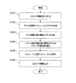
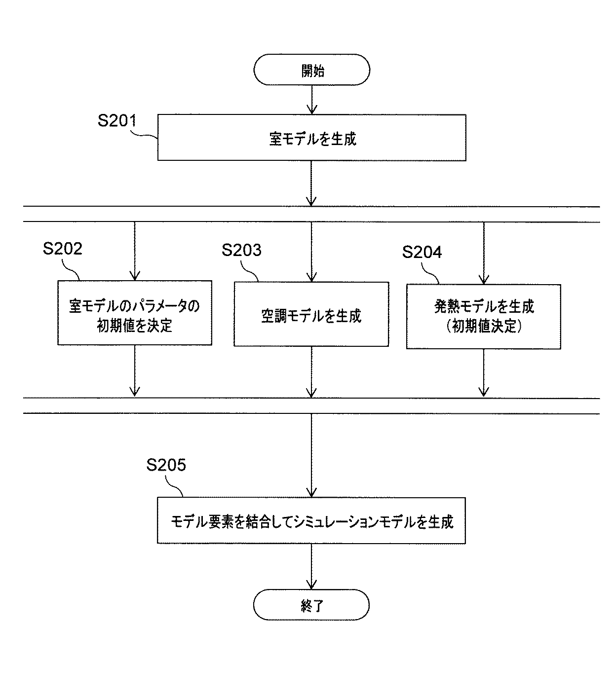
モデル生成部13が行う処理を、その処理の流れとともに説明する。図4は、第1の実施形態に係るモデル生成部の処理のフローチャートの一例を示す図である。なお、本実施形態では、モデル要素が数式で表されていると想定する。
A process performed by the
モデル生成部13は、まず、空調システムを備える建物に応じた室モデルを生成する(S201)。室モデルは、建物の室の熱量を示すモデルである。室は、建物の一部または全体の領域を示す。すなわち、室は建物全体でもよいし、建物の領域を等分に分割した際の一区分でもよいし、建物に実際に存在する部屋であってもよい。生成された室モデルの一例を次式に示す。なお、ここでは建物全体を1つの室と想定する。当該想定では、室は建物を意味する。
式(1−1)の例では、建物に、空調システムAと空調システムBとが存在することを想定する。空調システムAと空調システムBは異なる種類の空調システムである。例えば、換気を主目的とする空調システムと、温度調整を主目的とする空調システムとである。建物がどの空調システムを備えているかは、建物情報または空調システム特性に含まれていればよい。 In the example of Formula (1-1), it is assumed that the air conditioning system A and the air conditioning system B exist in a building. Air conditioning system A and air conditioning system B are different types of air conditioning systems. For example, an air conditioning system whose main purpose is ventilation and an air conditioning system whose main purpose is temperature adjustment. Which air conditioning system a building is equipped with may be included in the building information or air conditioning system characteristics.
Cは室内への熱の出入りに対する室温の変化量を示す係数を表すパラメータである。Uは壁の熱の伝わりやすさを示す係数を表すパラメータである。Aは建物(室)の表面積を表すパラメータである。ゆえに、数1に示された室モデルは、外気温Toutdoorと、熱量Q空調A、Q空調BおよびQ内部発熱と、を入力として、室温Troomを算出するモデルである。 C is a parameter that represents a coefficient indicating the amount of change in room temperature with respect to the entry and exit of heat into the room. U is a parameter representing a coefficient indicating the ease of heat transfer of the wall. A is a parameter representing the surface area of a building (room). Therefore, the room model shown in Equation 1 is a model for calculating the room temperature T room using the outside air temperature T outdoor and the heat quantity Q air conditioning A , Q air conditioning B and Q internal heat generation as inputs.
なお、複数の室がある場合は、各室ごとに室モデルが生成される。また、各室ごとに室モデルには、各室間の熱交換が考慮される。具体的には、隣接する室との間で交換される熱量が式(1−1)に追加され、隣接する室との間で交換される熱量を示す熱交換式が追加される。例えば、室1と室2の2つの室がある場合、室1のモデルにおける室2から流入する熱量を表す熱交換式は、次の式(1−3)で示される。
次に、モデル生成部13は、パラメータ推定値算出部15により推定値が算出されるパラメータに対して初期値を決定する(S202)。パラメータ推定値算出部15により推定値が算出されるパラメータは予め定められており、少なくとも簡略化モデル作成に用いられる計測データが計測された期間において一定の値であると想定されるものとする。例えば、壁の熱の伝わりやすさは、経年劣化により変化すると思われるが、計測データが計測されるような日、週単位の短い時間においては、変化しないとみなすことができる。上記の例では、パラメータC、U、およびAの初期値が決定される。パラメータの最終的な推定値はパラメータ推定値算出部15により決定されるが、パラメータの初期値はモデル生成部13により決定される。モデル生成部13は、建物情報に基づきパラメータの初期値を決定する。
Next, the
初期値の算出方法の一例を説明する。まず、モデル生成部13は、建物情報と、参照リストと、に基づきパラメータCの単位体積当たりの値を算出する。参照リストは、建物情報と、パラメータCの単位体積当たりの値との関係が示されたものである。例えば、室の用途と、パラメータCの単位体積当たりの値との対応表であってもよい。室が体育館等の運動施設であれば、室内に存在する物があまりないため、室温は変化しやすいと考えられる。一方、室が倉庫等であれば、室内に存在する物が多いため、室温が変化しにくいと考えられる。このように、パラメータCと関連性があると想定される建物情報と、パラメータCの単位体積当たりの値との関係を予め定めておき、参照リストとすればよい。なお、当該関係は、初期値とするため、厳格にする必要はない。参照リストは、記憶部12に記憶されていてもよいし、建物情報に含まれていてもよい。そして、パラメータCの単位体積当たりの値と、建物情報に含まれる床面積および階高に基づき算出された建物の体積と、を乗算することにより、パラメータCが算出されてもよい。
An example of an initial value calculation method will be described. First, the
パラメータUも、同様に、用途、築年数、所在地域などに基づき参照リストから算出されてもよい。例えば、所在地域が寒冷地であれば、外壁に高性能な断熱材が使われていると想定されるため、パラメータUの値は大きいと想定される。また、築年数が大きければ、断熱材の性能が低く、経年劣化等もあるため、パラメータUが小さいと想定される。用途が断熱の必要がない倉庫であれば、パラメータUが小さいと想定される。 Similarly, the parameter U may be calculated from the reference list based on the use, age, location, and the like. For example, if the location area is a cold region, it is assumed that a high-performance heat insulating material is used for the outer wall, so the value of the parameter U is assumed to be large. In addition, if the building age is large, the performance of the heat insulating material is low, and there is also aged deterioration, so the parameter U is assumed to be small. If the application is a warehouse that does not require heat insulation, the parameter U is assumed to be small.
パラメータAは、建物情報に基づき算出すればよい。建物情報に基づき正確に算出できる場合は、算出された値は初期値ではなく推定値としてもよく、パラメータ推定値算出部15に対し、推定値を算出する対象から外すような設定を行ってもよい。
The parameter A may be calculated based on building information. If it is possible to calculate accurately based on building information, the calculated value may be an estimated value instead of an initial value, and the parameter estimated
次に、モデル生成部13は、空調システムに応じた空調モデルを生成する(S203)。空調モデルは、空調システムによる熱量を示すモデルである。空調モデルの一例を、次式に示す。
空調機の種類と定格能力は、建物情報に含まれていてもよいし、建物情報に基づき決定されてもよい。例えば、建物の用途、床面積、所在地域などと、空調システムの定格能力との関係を示す参照リストを予め作成しておき、建物の用途、床面積、所在地域などから、定格能力が決定されてもよい。 The type and rated capacity of the air conditioner may be included in the building information, or may be determined based on the building information. For example, a reference list showing the relationship between the building usage, floor area, location area, etc. and the rated capacity of the air conditioning system is created in advance, and the rated capacity is determined from the building usage, floor area, location area, etc. May be.
次に、モデル生成部13は、発熱モデルを生成する(S204)。発熱モデルは、室に存在する発熱源による発熱量を示すモデルであり、室モデルに含まれる発熱量Q内部発熱を算出するためのモデルである。モデル生成部13は、建物情報と、発熱パターンと、に基づき、発熱モデルを生成する。例えば、室の単位面積当たりの発熱パターンが建物情報に含まれる用途と対応している場合、モデル生成部13は、室の用途に基づき発熱パターンを記憶部12から抽出し、抽出された発熱パターンと、建物情報に含まれる床面積と、を乗算することにより、発熱モデルを生成する。発熱モデルの一例を次式に示す。
モデル生成部13は、室モデルと、空調モデルと、発熱モデルと、を結合して、シミュレーションモデルを生成する(S205)。図5は、生成されたシミュレーションモデルの構成の一例を示す図である。図5には、生成されたシミュレーションモデル3が示されており、シミュレーションモデル3のモデル要素として、室モデル31と、空調モデル32Aと、空調モデル32Bと、発熱モデル33とが示されている。空調モデルは、2つの異なる種類の空調システムがあるため、2つ記載されている。発熱モデル33は、人体発熱モデル331と機器発熱モデル332を含んでいる。モデル生成部13は、あるモデル要素の出力の変数名と、別のモデル要素の入力の変数名とが一致している場合に、あるモデル要素の出力と別のモデル要素の入力とをリンクで接続する。これにより、モデル要素が接続されたシミュレーションモデルが生成される。以上が、モデル生成部13の処理のフローである。
The
以上のように、モデル生成部13は、空調システムを備える建物の室の熱量を示す室モデルと、空調システムによる熱量を示す空調モデルと、室に存在する発熱源による発熱量を示すモデルと、を構成要素として少なくとも含むシミュレーションモデルを生成する。
As described above, the
モデル簡略化部14は、計測データセットと、簡略化可能条件と、に基づき、シミュレーションモデルを簡略化することにより、計測データセットに対応する簡略化モデルを生成する。計測データセットは、単位期間ごとにまとめられた計測データを意味する。簡略化とは、シミュレーションモデルに含まれるモデル要素の一部を省くまたは単純化することである。例えば、人体からの発熱は無視できるとして、人体発熱モデルを省くといった簡略化がある。また、室温の変化が無視できる程度であれば、式(1−1)の左辺を0と単純化するといった簡略化がある。簡略化可能条件は、簡略化するための条件である。
The
図6は、簡略化可能条件の一例を示す図である。図6では、簡略化可能条件が一覧表にて示されている。なお、適用されない簡略化可能条件があってもよい。例えば、図6では、空調モデルに対して、IDが2aの簡略化可能条件と、IDが2bの簡略化可能条件とが設定されているが、いずれか一方または両方が適用されてもよい。図6の場合では、計測データに空調システムの発停に関するデータが含まれる場合には条件2aが用いられ、計測データに消費エネルギデータが含まれる場合は条件2bを用いられるとしてもよい。いずれの簡略化可能条件も適用でき、適用後の結果が異なる場合には、優先度の高い簡略化可能条件を優先させるようにしてもよい。例えば、簡略化可能条件の一覧表において、より上の行にある条件が優先されるといった規則を予め定めておいてもよい。また、簡略化可能条件の一覧表に、簡略化可能条件を満たす場合の処理、つまり簡略化の内容が設定されていてもよい。
FIG. 6 is a diagram illustrating an example of conditions that can be simplified. In FIG. 6, simplification possible conditions are shown in a list. There may be simplification conditions that do not apply. For example, in FIG. 6, the simplification possible condition with
モデル簡略化部14が行う処理を、その処理の流れとともに説明する。図7は、第1の実施形態に係るモデル簡略化部の処理のフローチャートの一例を示す図である。モデル簡略化部14は、まず、計測データと、シミュレーションモデルと、シミュレーションモデルに含まれるモデル要素の簡略化可能条件とを取得する(S301)。
A process performed by the
次に、モデル簡略化部14は、計測データの計測データセットごとに、計測データセットが簡略化可能条件を満たすかについて判定する(S302)。計測データセットが簡略化可能条件を満たさない場合(S302のNO)は、次の簡略化可能条件の判定に移る。簡略化可能条件を満たす場合(S302のYES)は、簡略化可能なモデル要素を記録して(S303)、次の簡略化可能条件の判定に移る。全ての簡略化可能条件を確認したら、次の計測データセットの確認に移る。このように、全ての計測データセットに対し、全ての簡略化可能条件を判定する。
Next, the
図8は、計測データセットおよび簡略化可能条件の判定結果の一例を示す図である。図8の上部(2から7行目)に計測データが示され、図8の下部(8から12行目)に計測データセットに基づく判定結果が示されている。各列における2行目から7行目に示された計測データの組が計測データセットである。計測データセットに基づき、図6に示された各簡略化可能条件が成立するかが判定され、当該判定結果が同じ列の8から12行目に格納される。例えば、図8の表の2列目には、時刻0:00における計測データセットは、室モデルの一部が簡略不可(図の×)と判定されたが、その他の簡略化可能条件が簡略可能(図の○)と判定されたことが示されている。なお、S303の判定結果の記録は、例えば、図8のように簡略化可能条件を満たすと判定された簡略化可能条件の判定結果を初期値×から○に変更するとしてもよいし、簡略化可能条件を満たすと判定された簡略化可能条件だけを記録するとしてもよい。 FIG. 8 is a diagram illustrating an example of measurement data sets and simplification possible condition determination results. Measurement data is shown in the upper part (2nd to 7th lines) of FIG. 8, and a determination result based on the measurement data set is shown in the lower part (8th to 12th lines) of FIG. A set of measurement data shown in the second to seventh rows in each column is a measurement data set. Based on the measurement data set, it is determined whether each simplification possible condition shown in FIG. 6 is satisfied, and the determination result is stored in the 8th to 12th rows of the same column. For example, in the second column of the table of FIG. 8, the measurement data set at time 0:00 was determined that a part of the room model could not be simplified (× in the figure), but other simplification conditions were simplified. It is shown that it was determined that it was possible (circle in the figure). The determination result recording in S303 may be performed by changing the determination result of the simplification possible condition determined to satisfy the simplification possible condition as shown in FIG. Only the simplification possible condition determined to satisfy the feasibility condition may be recorded.
そして、モデル簡略化部14は、計測データセットごとに、簡略化可能条件の判定結果に基づき、簡略化されたシミュレーションモデルを生成する。以降、簡略化されたシミュレーションモデルを、簡略化モデルと記載する。具体的には、モデル簡略化部14は、現在の処理の対象の計測データセットと簡略化可能条件の判定結果が同じである計測データセットに対する簡略化モデルが未だ生成されていないかを確認する(S304)。未生成の場合(S304のYES)は、簡略化可能条件の判定結果に基づき、現在の処理の対象の計測データセットに対応する簡略化モデルを生成する(S305)。既に生成されている場合(S304のNO)は、簡略化モデルを生成せずに、次の簡略化モデルに移る。これにより、複数の計測データセットのうち、簡略可能なモデル要素が異なる計測データセットに対して簡略化モデルが生成される。
And the
例えば、図8の時刻0:00における計測データセットに対して簡略化モデルの生成を行った後で、時刻0:10における計測データセットを処理する場合は、時刻0:00における計測データセットと時刻0:10における計測データセットとの判定結果が同一であるため、時刻0:10における計測データセットに対する簡略化モデルは生成されない。つまり、簡略化可能条件の判定結果の組み合わせごとに、1つの簡略化モデルが生成されることになる。 For example, when a simplified model is generated for the measurement data set at time 0:00 in FIG. 8 and the measurement data set at time 0:00 is processed, the measurement data set at time 0:00 Since the determination result with the measurement data set at time 0:10 is the same, a simplified model for the measurement data set at time 0:10 is not generated. That is, one simplified model is generated for each combination of determination results of simplification possible conditions.
最後に、モデル簡略化部14は、生成された簡略化モデルに関する情報を生成する(S306)。当該情報を簡略化モデル情報と記載する。図9は、簡略化モデル情報の一例を示す図である。簡略化モデル情報には、簡略化されたモデルのID、簡略化されたモデル要素数、簡略化モデルのパラメータ、簡略化モデルに対応する計測データセットなどが含まれている。なお、簡略化モデルのパラメータは、簡略化により削除されずに簡略化モデルに残っているパラメータである。簡略化モデル情報は、パラメータ推定値算出部15が行う処理において、処理の順番、推定の対象のパラメータ、用いる計測データセットを決めるための情報となる。以上が、モデル簡略化部14の処理のフローである。
Finally, the
パラメータ推定値算出部15は、簡略化モデルと、簡略化モデルに対応する計測データセットと、に基づき、簡略化モデルのパラメータに対する推定値を算出する。推定値の算出処理を、その処理の流れとともに説明する。図10は、推定値の算出処理のフローチャートの一例を示す図である。パラメータ推定値算出部15は、簡略化モデルと、簡略化モデル情報を取得する(S401)。
The parameter estimated
そして、パラメータ推定値算出部15は、簡略化モデルごとに、簡略化モデルのパラメータの推定値を算出する。この際、パラメータ推定値算出部15は、簡略化モデル情報に示された簡略化モデルに対応する計測データセットを用いる。
And the parameter estimated
また、本実施形態では、簡略化モデル情報に示された簡略化されたモデル要素数に基づき、処理される簡略化モデルの順序を決定する。具体的には、簡略化されたモデル要素数の多い簡略化モデルから先に、パラメータ推定値算出部15はパラメータの推定値を算出する。図9の例では、ID1の簡略化モデルの簡略化されたモデル要素数は5、ID2の簡略化モデルの簡略化されたモデル要素数は4、ID3の簡略化モデルの簡略化されたモデル要素数は2であるため、ID1、ID2、ID3の順で、簡略化モデルのパラメータの値が推定される。
In this embodiment, the order of the simplified models to be processed is determined based on the simplified number of model elements indicated in the simplified model information. Specifically, the parameter estimation
簡略化モデルごとの処理は、次のように行われる。まず、パラメータ推定値算出部15は、簡略化モデルに対して初期化を行う(S402)。初期化とは、簡略化モデルのパラメータに初期値を設定し、回帰計算の繰り返し回数を0にすることを意味する。当該初期値は、モデル生成部13により算出された初期値である。次に、パラメータ推定値算出部15は、シミュレーション部16に、パラメータの値が設定された簡略化モデルを入力する。シミュレーション部16は、入力された簡略化モデルに対するシミュレーションを実行し、シミュレーション結果を算出する(S403)。
Processing for each simplified model is performed as follows. First, the parameter estimated
次に、パラメータ推定値算出部15は、シミュレーション結果と、簡略化モデルに対応する計測データセットとに基づき、判定を行う。そして、判定結果に基づき、処理を決定する。例えば、シミュレーション結果と、対応する計測データセットを比較する(S404)。その差が予め定められた閾値以下の場合(S405のYES)は、所定条件を満たすとして、その時点でのパラメータの値を推定値とする。閾値より大きい場合(S405のNO)は、所定条件を満たさないとして、回帰計算の繰り返し回数を確認する(S406)。回帰計算の繰り返し回数が限度回数を超えている場合(S406のYES)は、その時点でのパラメータの値を推定値としてもよい。または、今までに設定したパラメータの値の中から推定値が選択されてもよい。回帰計算の繰り返し回数が限度回数を超えていない場合(S406のNO)は、パラメータ推定値算出部15は更新処理を行う。更新処理とは、パラメータの値を新たな値とし、回帰計算の繰り返し回数に1を加算することとする。新たな値は、例えば、現在の値に予め定められた変化量を加算することにより算出されてもよい。そして、新たなパラメータの値に基づき、簡略化モデルに対するシミュレーションが行われる(S403)。このS403からS407の処理が繰り返されて、パラメータの推定値が定まる。
Next, the parameter estimated
上記において、パラメータ推定値算出部15が設定するパラメータの値を候補値と定義する。候補値は、推定値の候補である。つまり、1回目の計算では、パラメータ推定値算出部15は、候補値として初期値を設定する。そして、シミュレーション結果と簡略化モデルに対応する計測データセットとに基づき判定を行い、判定結果に基づき、初期値を推定値とするかを決定する。2回目以降の計算では、パラメータ推定値算出部15は、新たな候補値を算出し、同様にして、新たな候補値を推定値とするかを決定する。なお、新たな候補値の算出方法は、最適化手法など、公知の手法を用いてもよい。
In the above, the parameter value set by the parameter estimated
最初の簡略化モデルに対して上記処理が行われた後に、次の簡略化モデルに対しても同処理が行われる。この際、先の処理により推定値が定まったパラメータに対しては、S402の初期化の処理において、当該パラメータに対し算出済みの推定値が適用されることとし、S407における更新処理の対象からは除外する。例えば、パラメータ推定値算出部15は、時刻4:00の計測データセットに基づく簡略化モデルのパラメータUに対する推定値を算出した後は、時刻0:00の計測データセットに基づく簡略化モデルのパラメータUに対しては、先に算出した推定値を適用する。これは、計測データセットが計測された時刻0:00と時刻4:00との間の期間において、パラメータUの値は変化しないと想定されるため、パラメータUの推定値を個々の簡略化モデルによらずに一定の値とするためである。こうして、全ての簡略化モデルに対して処理が行われ、推定値の算出処理は終了する。
After the above process is performed on the first simplified model, the same process is performed on the next simplified model. At this time, for the parameter for which the estimated value is determined by the previous process, the estimated value calculated for the parameter is applied in the initialization process in S402. exclude. For example, after the parameter estimated
ゆえに、本実施形態は、計測データセットごとの簡略化モデルを生成しても、値が変動すべきでないパラメータについては一意な値となる。 Therefore, in the present embodiment, even if a simplified model is generated for each measurement data set, a parameter whose value should not change is a unique value.
シミュレーション部16は、パラメータの推定値に基づき、空調システムに係るシミュレーションモデルに対してシミュレーションを行い、空調システムのシミュレーション結果を算出する。こうして、適切とされるパラメータ値により、空調システムを評価するためのシミュレーション結果を算出することができる。
The
シミュレーション部16は、EnergyPlus、TRANSYSなどのエネルギーシミュレーションプログラムで実現されてもよいし、MATLAB/Simulink、Modelica、Pythonなどの汎用的なプログラム実行環境で実現されてもよいし、C++、Fortranなどの汎用的なプログラミング言語で記述されたシミュレーションプログラムとそれらをコンパイルするためのコンパイラの組み合わせで実現されてもよい。
The
なお、上記説明では、シミュレーション部16が、候補値に基づき、簡略化モデルに対するシミュレーションを行うとした。しかし、簡略化モデルに対するシミュレーションと空調システムに係るシミュレーションモデルに対するシミュレーションとを異なるシミュレーション部が行ってもよい。つまり、候補値に基づき簡略化モデルに対するシミュレーションを行う第1のシミュレーション部と、パラメータ推定値算出部15が算出した推定値に基づきシミュレーションモデルに対するシミュレーションを行う第2のシミュレーション部と、を空調システム評価装置1が備えていてもよい。第1のシミュレーション部は、パラメータ推定値算出部に含まれてもよい。第1のシミュレーション部と、第2のシミュレーション部は、同一のシミュレーション環境でもよいし、異なるシミュレーション環境でもよい。例えば、両シミュレーションのうち一方の負荷を減らすために、一方のシミュレーションは、他方のシミュレーションよりも簡易にしてもよい。
In the above description, the
出力インタフェース17は、空調システム評価装置1の各構成要素から情報を受取り、受け取った情報を出力する。例えば、出力インタフェース17は、空調システムのシミュレーション結果を表示する。出力インタフェース17は、空調システムのシミュレーション結果を表示するシミュレーション結果表示インタフェースを用いて、空調システムのシミュレーション結果を表示してもよい。図11は、第1の実施形態に係る、空調システムのシミュレーション結果の一例を示す図である。図11は、シミュレーション結果として、1年間の各月における空調システムに関する機器ごとの消費エネルギ量を示す。図11の消費エネルギ量は、エアハンドリングユニット、空調システムA、空調システムB、熱源機A、および熱源機Bの消費エネルギ量から構成されている。なお、空調システムのシミュレーション結果は、室内の温度を示すものであってよいし、各機器の負荷率または稼働率を示すものであってもよい。
The
なお、出力インタフェース17が出力する情報は、特に限られるものではない。空調システム評価装置1の各構成要素の処理結果を出力してもよい。例えば、シミュレーションモデル、簡略化モデル、簡略化可能条件の判定結果、簡略化モデル情報、パラメータの推定値でもよい。また、処理に用いられたモデル要素、発熱パターン、空調システム特性、計測データ、参照リスト、簡略化可能条件などを出力してもよい。また、出力方法は、ディスプレイに画像を表示してもよいし、情報をファイル形式のデータにして送信してもよい。
Information output by the
以上のように、本実施形態によれば、ある時間帯の計測データに基づく簡略化モデルを用いて一部のパラメータを同定し、別の時間帯の計測データに基づく簡略化モデルを用いて残りのパラメータを同定する。これにより、変動すべきでないパラメータの値が簡略化モデルごとに異なるといった事態を防ぐことができる。また、推定すべきパラメータの数が減るため、処理負荷が減り、処理の時間を短くすることができる。このようにして、建物に合わせた空調システム評価装置を実現することができる。 As described above, according to the present embodiment, some parameters are identified using a simplified model based on measurement data in a certain time zone, and the remaining parameters are identified using a simplified model based on measurement data in another time zone. Identify the parameters. As a result, it is possible to prevent a situation in which the value of the parameter that should not be changed differs for each simplified model. Further, since the number of parameters to be estimated is reduced, the processing load is reduced and the processing time can be shortened. In this way, it is possible to realize an air conditioning system evaluation apparatus tailored to a building.
なお、上記の実施形態は一例であり、例えば、モデル生成部13を備えるモデル生成機と、モデル簡略化部14と、パラメータ推定値算出部15と、第1のシミュレーション部とを備えるパラメータ推定機と、第2のシミュレーション実行部を備えるシミュレーション機とが有線で接続されることにより、空調システム評価装置1が構成されていてもよい。また、上記のモデル生成デバイス機、パラメータ推定機、およびシミュレーション機が独立した装置であり、それぞれが無線でデータを送受信することにより、空調システム評価システムが構成されてもよい。
In addition, said embodiment is an example, For example, the parameter estimator provided with the model generator provided with the model production |
なお、記載したフローチャートは一例であり、必要とされる処理結果を得ることができれば処理の順序等は限られるものではない。例えば、図4に示したS203、S204、S205のステップは、並列に行われてもよいし、ステップ番号の順に行われてもよいし、順序が入れ替えられてもよい。また、各処理の処理結果は記憶部12に逐次記憶され、各構成要素は記憶部12を参照して処理結果を取得してもよい。
Note that the described flowchart is an example, and the order of the processing is not limited as long as a required processing result can be obtained. For example, the steps S203, S204, and S205 illustrated in FIG. 4 may be performed in parallel, may be performed in the order of step numbers, or the order may be changed. In addition, the processing result of each process may be sequentially stored in the
(第2の実施形態)
第2の実施形態では、ユーザ等がモデル詳細度を設定する。モデル詳細度は、シミュレーションモデルの詳細度を示すものである。例えば、対象の建物を複数の室に区切るための情報が含まれる。モデル詳細度をユーザ等が設定できるため、より柔軟に建物の空調システムを評価することができる。第2の実施形態は、入力インタフェース11がユーザ等からモデル詳細度を受け付け、モデル生成部13が受け付けたモデル詳細度を考慮してモデルを生成する以外は、第1の実施形態と同様である。第1の実施形態と同様の点は説明を省略する。
(Second Embodiment)
In the second embodiment, the user or the like sets the model detail level. The model detail level indicates the detail level of the simulation model. For example, information for dividing the target building into a plurality of rooms is included. Since the user can set the model detail level, the building air conditioning system can be evaluated more flexibly. The second embodiment is the same as the first embodiment except that the
入力インタフェース11は、建物情報に加えて、モデル詳細度を受け付ける。指定されるモデル詳細度は、例えば、建物全体を1つの室とする、建物全体を2つの室とするといった指定でもよい。または、建物を、最上階、最下階およびその他の中間階に分割するといった指定でもよい。または、ISO 13790:2008といったモデル要素が満たすべき規格を指定してもよいし、EnergyPlusのようなシミュレーションツールを指定してもよい。
The
図12は、モデル詳細度を設定するためのインタフェースの一例を示す図である。以降、モデル詳細度を設定するためのインタフェースを、モデル詳細度設定インタフェースと記載する。例えば、ユーザがモデル詳細度を設定する際に、入力インタフェース11は、図12(A)に示すモデル詳細度設定インタフェース4を、有線または無線で接続されたディスプレイ等に表示する。種類指定領域41は、指定するモデル詳細度の種類を設定する領域である。ゾーン数指定領域42は、建物の水平面を分割する数(ゾーン数)を入力する領域である。階高分割数指定領域43は、建物の鉛直面を分割する数(階高分割数)を入力する領域である。生成される室モデルは、ゾーン数×階高分割数で算出される個数分の室を有することになる。生成ボタン44はボタンであり、ボタンを押下すると、入力された情報に基づき、室モデルを生成するようモデル生成部13に命令が送られる。図12の例では、ゾーン数が2と、階高分割数が3と入力されているため、6つの室モデルが生成される。
FIG. 12 is a diagram illustrating an example of an interface for setting the model detail level. Hereinafter, an interface for setting the model detail level is referred to as a model detail level setting interface. For example, when the user sets the model detail level, the
また、種類指定領域41に示された種類が変更されることにより、モデル詳細度設定インタフェースがその種類に応じた画面に変更されてもよい。例えば、図12(A)の種類指定領域41に示されたプルダウンを「数式モデル」から「ISO」に変更した画面を図12(B)に、「EnergyPlus」に変更した画面を図12(C)に示す。図12(B)および(C)では、選択した種類に応じて、選択不可能な領域が表示されていない。このように、モデル詳細度設定インタフェースは、指定される種類に応じた画面を表示してもよい。
Further, by changing the type indicated in the
第2の実施形態のモデル生成部13は、モデル詳細度指定インタフェースで指定された詳細度に基づき、室モデルを生成する。つまり、指定された個数分の室モデルを生成する。複数の室モデルが指定された場合は、各室モデルには各室モデル間の熱交換式が含まれる。
The
図13は、第2の実施形態に係るモデル生成部の処理のフローチャートの一例を示す図である。モデル生成部13は、指定されたモデル詳細度の種類を確認し、数式モデル以外が指定された場合(S401の数式モデル以外を指定)は、指定された種類に応じた処理を実行する(S402)。例えば、ISO規格が指定された場合は、シミュレーションモデルのパラメータファイルを出力してもよい。また、シミュレーションツールが指定された場合は、シミュレーションツールに応じたモデルを生成してもよい。数式モデルが指定された場合(S401の数式モデルを指定)は、モデル生成部13は、ゾーン数×階高分割数で算出される個数分の室モデルを生成する(S403)。そして、第1の実施形態と同様に、S202からS205の処理が行われ、シミュレーションモデルが生成される。これにより、詳細度に基づき生成された室モデルがシミュレーションモデルに含まれる。以上が、第2の実施形態に係るモデル生成部13の処理のフローである。
FIG. 13 is a diagram illustrating an example of a flowchart of processing of the model generation unit according to the second embodiment. The
以上のように、本実施形態によれば、ユーザ等がモデル詳細度を設定することが可能となる。これにより、より建物の実態に即して空調システムを評価することが可能となる。 As described above, according to the present embodiment, the user or the like can set the model detail level. Thereby, it becomes possible to evaluate the air conditioning system in accordance with the actual condition of the building.
(第3の実施形態)
第3の実施形態では、ユーザ等が建物運用情報を設定する。建物運用情報は、建物または建物内の施設もしくは設備の運用に関する情報である。また、簡略化可能条件には、建物運用情報に係る条件が含まれ、当該条件を判定するために建物運用情報が用いられる。
(Third embodiment)
In the third embodiment, a user or the like sets building operation information. The building operation information is information relating to the operation of the building or the facility or equipment in the building. The simplification possible condition includes a condition related to building operation information, and the building operation information is used to determine the condition.
第3の実施形態では、入力インタフェース11が、建物情報等に加えて、建物運用情報を受け付ける。また、モデル簡略化部14が、建物運用情報に基づき、簡略化可能条件を判定し、シミュレーションモデルを簡略化する。入力インタフェース11は、建物運用情報を受け付けるためのインタフェースである建物運用情報設定インタフェースを有線または無線で接続されたディスプレイ等に表示してもよい。また、建物運用情報が格納されたファイルを受け取ってもよい。また、建物運用情報が格納された外部の記憶装置を参照してもよい。上記以外は、これまでの実施形態と同様としてよい。これまでの実施形態と同様の点は説明を省略する。
In the third embodiment, the
建物運用情報は、建物または建物内の施設もしくは設備の稼働予定に関する情報であってもよい。図14は、第3の実施形態に係る簡略化可能条件の一例を示す図である。図6の簡略化可能条件の一覧表と比較すると、IDが3aの簡略化可能条件が追加されている。これは、予め指定されたビル(建物)の稼働時間外であれば常時運転する機器以外の機器は停止しているとみなせるため、常時運転している機器以外の室内機器に関する発熱モデルを簡略化するという条件である。また、IDが4aの簡略化可能条件が追加されている。これは、予め指定されたビル(建物)の稼働時間外であれば、在室者が極端に少ないとみなせるため、室内の人体発熱モデルを簡略化するという条件である。このように、建物運用情報により、発熱モデルを簡略化することができる。
The building operation information may be information related to an operation schedule of a building or a facility or equipment in the building. FIG. 14 is a diagram illustrating an example of the simplification possible condition according to the third embodiment. Compared with the list of simplification possible conditions in FIG. 6, a simplification possible condition with ID 3a is added. This is because it can be considered that equipment other than the equipment that is always operating is stopped if it is outside the operating time of the building (building) specified in advance, so the heat generation model related to indoor equipment other than the equipment that is always operating is simplified. It is a condition to do. Moreover, the simplification possible condition of
なお、図14では、建物全体の稼働時間であったが、室、設備の個別の運用情報であってもよい。例えば、室が事務所または店舗である場合の室の営業時間でもよい。営業時間外における室の発熱量は少ないことが予測されるため、室の用途が事務所等であって営業時間外のときは、当該室における発熱モデルを簡略化するという簡略化条件を設定することができる。また、建物運用情報は、例えば、室内の生体の数の具体的な時系列推移を示す情報であってもよい。その場合、室内の生体の数が所定数よりも減少する時間帯においては、当該室における発熱モデルを簡略化するという簡略化条件を設定することができる。例えば、設備の運転条件は空調の運転時間などであってもよい。その場合、運転時間外においては該当する空調モデルを簡略化することが可能となる。 In addition, in FIG. 14, although it was the operation time of the whole building, the separate operation information of a room and an installation may be sufficient. For example, the business hours of a room when the room is an office or a store may be used. Because it is predicted that the amount of heat generated in the room outside of business hours will be small, when the room is used for offices etc. and it is outside business hours, set a simplified condition to simplify the heat generation model in the room be able to. Further, the building operation information may be information indicating a specific time series transition of the number of living organisms in the room, for example. In that case, in a time zone in which the number of living organisms in the room is less than a predetermined number, a simplified condition for simplifying the heat generation model in the room can be set. For example, the operating condition of the facility may be an air conditioning operating time. In that case, it becomes possible to simplify the corresponding air conditioning model outside the operation time.
なお、室の用途は、特に限られるものではなく、事務所、店舗意外にも、住居、倉庫等でもよい。室の稼働予定は、営業時間以外にも、室の開放時間でも、室の閉鎖時間でもよい。建物内の設備も、特に限られるものではない。また、設備の稼働予定は、設備の起動と停止が判断できる情報の他、起動しているが待機の状態であるアイドリング時間でもよい。また、稼働予定は1日の予定ではなく、週、月単位の長期間の予定でもよい。例えば、毎月の休業日などの予定でもよい。 The usage of the room is not particularly limited, and may be a residence, a warehouse, or the like other than an office or a store. The operating schedule of the room may be the opening time of the room or the closing time of the room in addition to the business hours. The facilities in the building are not particularly limited. Moreover, the operation schedule of the equipment may be an idling time in which the equipment is activated but is in a standby state, in addition to information that can determine whether the equipment is activated or stopped. Further, the operation schedule may not be a one-day schedule, but may be a weekly or monthly long-term schedule. For example, it may be a schedule such as a monthly holiday.
なお、これまでの実施形態でも、計測データに基づき在室者が極端に少ない等を判断し簡略化することはできる。しかし、そのためには入退室を計測するセンサを室ごとに用意する必要がある。しかし、本実施形態では、判断のための計測データが不要となるため、計測データの収集のコストを減らすことができる。 In the embodiments described so far, it can be simplified by determining that the number of people in the room is extremely small based on the measurement data. However, for that purpose, it is necessary to prepare a sensor for measuring the entrance and exit of each room. However, in the present embodiment, measurement data for determination is not necessary, so that the cost of collecting measurement data can be reduced.
このように、建物運用情報を受け付けることにより、建物運用情報に基づく簡略化が可能となり、より簡略化されたシミュレーションモデルを作成することができる。 In this way, by receiving the building operation information, simplification based on the building operation information is possible, and a more simplified simulation model can be created.
以上のように、本実施形態によれば、建物運用情報を用いた簡略化可能条件を設定することができるため、より適切な簡略化モデルを生成することができる。 As described above, according to the present embodiment, it is possible to set simplification possible conditions using building operation information, and therefore it is possible to generate a more appropriate simplified model.
(第4の実施形態)
第4の実施形態では、ユーザ等がパラメータを推定する簡略化モデルの順序を指定する。これまでの実施形態では、パラメータ推定値算出部15が簡略化されたモデル要素の多い簡略化モデルから順にパラメータを推定した。本実施形態では、パラメータ推定値算出部15は、指定された順序に基づき、簡略化モデルのパラメータを推定する。これまでの実施形態と同様の点は説明を省略する。
(Fourth embodiment)
In the fourth embodiment, the user or the like specifies the order of simplified models for estimating parameters. In the embodiments so far, the parameter estimation
出力インタフェース17は、モデル簡略化部14により算出された簡略化モデルに関する情報を出力する。例えば、図9に示した簡略化モデル情報を出力してもよい。
The
入力インタフェース11は、建物情報等に加えて、パラメータの推定値が算出される簡略化モデルの順序を受け付ける。全ての簡略化モデルに対して順序が定められてもよいし、一部の簡略化モデルに対して順序が定められてもよい。入力インタフェース11は、パラメータ推定順序を受け付けるためのインタフェースであるパラメータ推定順序指定インタフェースを有線または無線で接続されたディスプレイ等に表示してもよい。また、パラメータ推定順序が格納されたファイルを受け取ってもよい。また、パラメータ推定順序が格納された外部の記憶装置を参照してもよい。
The
パラメータ推定値算出部15は、パラメータの推定値が算出される簡略化モデルの順序を、入力インタフェース11で受け付けた順序とする。一部の簡略化モデルに対して順序が与えられた場合、残りの簡略化モデルに対しては、これまでの実施形態と同様に、パラメータ推定値算出部15が順序を決定する。これにより、図10で示したフローにおいて、簡略化モデルの数の多い順ではなく、受け付けた順序で、簡略化モデルに対し、パラメータの推定値が算出される。
The parameter estimation
パラメータ推定の順序を受け付けることにより、運転条件による変動が少ないパラメータを先に推定するというようなユーザの経験に基づく判断をパラメータ推定の処理に反映させることが可能となる。 By accepting the order of parameter estimation, it is possible to reflect in the parameter estimation process a judgment based on the user's experience such as estimating a parameter with less fluctuation due to operating conditions.
図15は、第4の実施形態に係る空調システム評価装置の全体処理の概略フローチャートの一例を示す図である。ステップS101からS103までの処理は、第1の実施形態と同じである。モデル簡略化部が簡略化モデルを生成した後は、出力インタフェース17が簡略化モデルに関する情報を出力する(S501)。そして、入力インタフェース11が、出力された情報に基づきユーザ等により入力された順序を受け付ける(S502)。当該順序は、パラメータ推定値算出部15に送られ、パラメータ推定値算出部15は、当該順序に応じて簡略化モデルを処理し、各簡略化モデルのパラメータの推定値を算出する(S503)。以降は、これまでの実施形態のフローと同様である。以上が、第4の実施形態に係る空調システム評価装置1の全体処理の概略フローとなる。
FIG. 15 is a diagram illustrating an example of a schematic flowchart of the overall processing of the air conditioning system evaluation apparatus according to the fourth embodiment. The processing from step S101 to S103 is the same as in the first embodiment. After the model simplification unit generates the simplified model, the
以上のように、本実施形態によれば、パラメータを推定する簡略化モデルの順序をユーザ等が指定できるため、より柔軟に建物の空調システムを評価することができる。 As described above, according to the present embodiment, since the user or the like can specify the order of the simplified models for estimating the parameters, the building air conditioning system can be evaluated more flexibly.
(第5の実施形態)
第5の実施形態では、ユーザ等が空調システムに係るシミュレーションの条件を示すシミュレーション条件を入力する。第5の実施形態は、入力インタフェース11がユーザ等からシミュレーション条件を受け付け、シミュレーション部16が、シミュレーション条件に基づき、空調システムに係るシミュレーションを行う。上記以外は、これまでの実施形態と同様としてよい。これまでの実施形態と同様の点は説明を省略する。
(Fifth embodiment)
In the fifth embodiment, a user or the like inputs a simulation condition indicating a simulation condition related to the air conditioning system. In the fifth embodiment, the
シミュレーション条件は、例えば、空調システムに係るシミュレーションモデルに含まれる特定の変数を変動させ、残りは定数とするような条件でもよい。また、変動させる変数の範囲を指定してもよいし、複数の取り得る値の候補を指定してもよい。 The simulation condition may be, for example, a condition in which a specific variable included in the simulation model related to the air conditioning system is changed and the rest is a constant. Further, the range of the variable to be changed may be designated, or a plurality of possible value candidates may be designated.
図16は、第5の実施形態に係る、空調システムのシミュレーション結果の一例を示す図である。図16のシミュレーション結果は、建物がセントラル空調と個別空調とを併用する場合に、個別空調の定格容量を変更するというシミュレーション条件が指定された場合のシミュレーション結果の例である。個別空調の定格容量の変化に応じた消費エネルギ
が示されている。図16では、個別空調の定格能力が上がるにつれて、セントラル空調の消費エネルギが下がることが示されている。しかし、総消費エネルギは始め下降するが、ある地点から上昇している。ゆえに、セントラル空調の定格能力は当該地点よりも大きくする必要がないことがわかる。これにより、セントラル空調を更改する際に、個別空調の定格能力を決定する指標とすることができる。
FIG. 16 is a diagram illustrating an example of a simulation result of the air conditioning system according to the fifth embodiment. The simulation result of FIG. 16 is an example of the simulation result when the simulation condition of changing the rated capacity of the individual air conditioning is specified when the building uses both the central air conditioning and the individual air conditioning. The energy consumption according to the change of the rated capacity of individual air conditioning is shown. FIG. 16 shows that the energy consumption of the central air conditioning decreases as the rated capacity of the individual air conditioning increases. However, the total energy consumption begins to drop, but rises from a certain point. Therefore, it can be seen that the rated capacity of the central air conditioning does not need to be larger than that point. Thereby, when renewing central air-conditioning, it can be set as the index which determines the rated capacity of individual air-conditioning.
図17は、第5の実施形態に係る、空調システムのシミュレーション結果の他の一例を示す図である。X軸は空調の給気温度を示す。Y軸は空調システムに用いられるチラー冷水の温度(チラー冷水温度)を示す。Z軸は消費電力を示す。図に示された各点は、給気温度およびチラー冷水温度の値を変えて行われたシミュレーション結果を示す。このようなシミュレーションを行う際に、空調システムに応じた給気温度およびチラー冷水機の規格に応じたチラー冷水温度の範囲を制限するようなシミュレーション条件を入力する。そうすることにより、不要な範囲のシミュレーションを除くことができる。 FIG. 17 is a diagram illustrating another example of the simulation result of the air conditioning system according to the fifth embodiment. The X axis indicates the supply temperature of the air conditioning. The Y axis indicates the temperature of the chiller cold water used in the air conditioning system (chiller cold water temperature). The Z axis indicates power consumption. Each point shown in the figure indicates a simulation result performed by changing the values of the supply air temperature and the chiller cold water temperature. When such a simulation is performed, a simulation condition that limits the range of the supply air temperature according to the air conditioning system and the chiller cold water temperature according to the specifications of the chiller chiller is input. By doing so, an unnecessary range of simulation can be eliminated.
シミュレーション条件は、シミュレーション部16が算出してもよい。例えば、ユーザが入力した建物の所在地域、建物周辺の気象情報から、シミュレーション部16が外気温などの変数の値の範囲を示すシミュレーション条件を算出してもよい。また、空調システム、空調システムに属する機器、または熱源機などの種別、機種名、設定情報、または運転スケジュールなどから、これらの機器に関する変数の取り得る値の範囲を定めてもよい。例えば、空調機の機種名が指定された場合、シミュレーション部16は記憶部12の空調システム特性を参照し、機種名から当該機種の給気量の取り得る範囲を抽出してもよい。なお、設定情報には、目標温度、吹出し温度、風量、運転モードなどが含まれる。また、建物内の人の移動スケジュール、施設の営業時間などから発熱量に関するシミュレーション条件を算出してもよい。このように、建物または前記建物内の施設もしくは設備に関する情報に基づくシミュレーション条件が生成され、当該シミュレーション条件に基づき、シミュレーションモデルに対するシミュレーションが行われてもよい。
The simulation condition may be calculated by the
以上のように、本実施形態によれば、所望の条件におけるシミュレーション結果を得ることができる。 As described above, according to the present embodiment, a simulation result under a desired condition can be obtained.
また、上記に説明した実施形態における各処理は、ソフトウェア(プログラム)により実現することが可能である。ゆえに、上記に説明した実施形態は、例えば、汎用のコンピュータ装置を基本ハードウェアとして用い、コンピュータ装置に搭載された中央処理装置(CPU:Central Processing Unit)等のプロセッサにプログラムを実行させることにより、実現することが可能である。 In addition, each process in the embodiment described above can be realized by software (program). Therefore, the embodiment described above uses, for example, a general-purpose computer device as basic hardware, and causes a processor such as a central processing unit (CPU) installed in the computer device to execute a program. It is possible to realize.
図18は、本発明の一実施形態におけるハードウェア構成の一例を示すブロック図である。空調システム評価装置およびパラメータ推定装置は、プロセッサ51と、主記憶装置52と、補助記憶装置53と、ネットワークインタフェース54と、デバイスインタフェース55とを備え、これらがバス56を介して接続されたコンピュータ装置5として実現できる。
FIG. 18 is a block diagram illustrating an example of a hardware configuration according to an embodiment of the present invention. The air conditioning system evaluation apparatus and parameter estimation apparatus include a
本実施形態における空調システム評価装置およびパラメータ推定装置は、各装置で実行されるプログラムをコンピュータ装置5に予めインストールすることで実現してもよいし、プログラムをCD−ROMなどの記憶媒体に記憶して、あるいはネットワークを介して配布して、コンピュータ装置5に適宜インストールすることで実現してもよい。
The air conditioning system evaluation device and the parameter estimation device in the present embodiment may be realized by installing in advance the program executed by each device in the
プロセッサ51は、コンピュータの制御装置および演算装置を含む電子回路である。プロセッサ51は、コンピュータ装置5の内部構成の各装置などから入力されたデータやプログラムに基づいて演算処理を行い、演算結果や制御信号を各装置等に出力する。具体的には、プロセッサ51は、コンピュータ装置5のOS(オペレーティングシステム)や、アプリケーションなどを実行し、コンピュータ装置5を構成する各装置を制御する。空調システム評価装置およびパラメータ推定装置の各構成要素の各処理は、プロセッサ51により実現することができる。
The
プロセッサ51は、上記の処理を行うことができれば特に限られるものではない。プロセッサ51は、例えば、汎用目的プロセッサ、中央処理装置(CPU)、マイクロプロセッサ、デジタル信号プロセッサ(DSP)、コントローラ、マイクロコントローラ、状態マシンなどでもよい。また、プロセッサ51は、特定用途向け集積回路、フィールドプログラマブルゲートアレイ(FPGA)、プログラム可能論理回路(PLD)に組み込まれていてもよい。また、プロセッサ51は、複数の処理装置から構成されていてもよい。例えば、DSPおよびマイクロプロセッサの組み合わせでもよいし、DSPコアと協働する1つ以上のマイクロプロセッサでもよい。
The
主記憶装置52は、プロセッサ51が実行する命令および各種データ等を記憶する記憶装置であり、主記憶装置52に記憶された情報がプロセッサ51により直接読み出される。補助記憶装置53は、主記憶装置52以外の記憶装置である。なお、記憶装置は、電子情報を格納可能な任意の電子部品を意味するものとする。主記憶装置52として、RAM、DRAM、SRAM等の一時的な情報の保存に用いられる揮発性メモリが主に用いられるが、本発明の実施形態において、主記憶装置52がこれらの揮発性メモリに限られるわけではない。主記憶装置52および補助記憶装置53として用いられる記憶装置は、揮発性メモリでもよいし、不揮発性メモリでもよい。不揮発性メモリは、プログラム可能読み出し専用メモリ(PROM)、消去可能プログラム可能読み出し専用メモリ(EPROM)、電気的消去可能PROM(EEPROM)、不揮発性ランダムアクセスメモリ(NVRAM)、フラッシュメモリ、MRAM等がある。また、補助記憶装置53として磁気または光学のデータストレージが用いられてもよい。データストレージとしては、ハードディスク等の磁気ディスク、DVD等の光ディスク、USB等のフラッシュメモリ、および磁気テープなどが用いられてもよい。主記憶装置52または補助記憶装置53により、記憶部12が実現されてもよい。
The
なお、プロセッサ51が主記憶装置52または補助記憶装置53に対して、直接または間接的に、情報を読み出しまたは書き込みまたはこれらの両方を行うならば、記憶装置はプロセッサと電気的に通信すると言うことができる。なお、主記憶装置52は、プロセッサに統合されていてもよい。この場合も、主記憶装置52は、プロセッサと電気的に通信していると言うことができる。
Note that if the
ネットワークインタフェース54は、無線または有線により、通信ネットワークに接続するためのインタフェースである。ネットワークインタフェース54は、既存の通信規格に適合したものを用いればよい。ここではネットワークインタフェース54を1つのみ示しているが、複数のネットワークインタフェース54が搭載されていてもよい。ネットワークインタフェース54により、通信ネットワーク6を介して通信接続された外部装置7に出力結果などが送信されてもよい。外部装置7は、外部記憶媒体でもよいし、入力デバイスまたは出力デバイスでもよいし、記憶部12を実現したストレージでもよい。
The
デバイスインタフェース55は、出力結果などを記録する外部記憶媒体と接続するUSBなどのインタフェースである。外部記憶媒体は、HDD、CD−R、CD−RW、DVD−RAM、DVD−R、SAN(Storage area network)等の任意の記録媒体でよい。また、デバイスインタフェース55を介して、記憶部12を実現したストレージなどと接続されていてもよい。また、キーボード、マウス、タッチパネル等の入力デバイス、LCD(Liquid Crystal Display)、CRT(Cathode Ray Tube)、PDP(Plasma Display Panel)、スピーカ等の出力デバイスと接続されてもよい。
The
入力インタフェース11および出力インタフェース17は、ネットワークインタフェース54またはデバイスインタフェース55を介して、入力デバイスまたは出力デバイスに対して情報の入出力を行えばよい。
The
また、コンピュータ装置5の一部または全部、つまり空調システム評価装置およびパラメータ推定装置の一部または全部は、プロセッサ51などを実装している半導体集積回路などの専用の電子回路(すなわちハードウェア)にて構成されてもよい。専用のハードウェアは、RAM、ROMなどの記憶装置との組み合わせで構成されてもよい。
Further, a part or all of the
なお、図18では、1台のコンピュータ装置が示されているが、ソフトウェアが複数のコンピュータ装置にインストールされてもよい。当該複数のコンピュータ装置それぞれがソフトウェアの異なる一部の処理を実行することにより、処理結果を生成してもよい。 In FIG. 18, one computer apparatus is shown, but software may be installed in a plurality of computer apparatuses. A processing result may be generated by each of the plurality of computer devices executing a part of processing different in software.
上記に、本発明の一実施形態を説明したが、これらの実施形態は、例として提示したものであり、発明の範囲を限定することは意図していない。これら新規な実施形態は、その他の様々な形態で実施されることが可能であり、発明の要旨を逸脱しない範囲で、種々の省略、置き換え、変更を行うことができる。これら実施形態やその変形は、発明の範囲や要旨に含まれるとともに、特許請求の範囲に記載された発明とその均等の範囲に含まれる。 Although one embodiment of the present invention has been described above, these embodiment are presented as examples and are not intended to limit the scope of the invention. These novel embodiments can be implemented in various other forms, and various omissions, replacements, and changes can be made without departing from the scope of the invention. These embodiments and modifications thereof are included in the scope and gist of the invention, and are included in the invention described in the claims and the equivalents thereof.
1 空調システム評価装置(パラメータ推定装置)
11 入力インタフェース(入力IF)
12 記憶部
13 モデル生成部
14 モデル簡略化部
15 パラメータ推定値算出部
16 シミュレーション部
17 出力インタフェース(出力IF)
2 建物情報入力インタフェース
21 BIM読み込み領域
22 概要指定領域
23 画像表示領域
3 シミュレーションモデル
31 室モデル
32A、32B 空調モデル
33 発熱モデル
331 人体発熱モデル
332 機器発熱モデル
4 モデル詳細度設定インタフェース
41 種類指定領域
42 ゾーン数指定領域
43 階高分割数指定領域
44 生成ボタン
5 コンピュータ装置
51 プロセッサ
52 主記憶装置
53 補助記憶装置
54 ネットワークインタフェース
55 デバイスインタフェース
56 バス
6 通信ネットワーク
7 外部装置
1 Air conditioning system evaluation device (parameter estimation device)
11 Input interface (input IF)
DESCRIPTION OF
2 Building
Claims (15)
計測データセットと、簡略化可能条件と、に基づき、前記シミュレーションモデルを簡略化することにより、前記計測データセットに対応する簡略化モデルを生成するモデル簡略化部と、
前記簡略化モデルと、前記簡略化モデルに対応する計測データセットと、に基づき、前記簡略化モデルのパラメータに対する推定値を算出するパラメータ推定値算出部と、
を備え、
前記パラメータ推定値算出部は、第1の計測データセットに基づく第1の簡略化モデルの第1のパラメータに対する第1の推定値を算出した後は、第2の計測データセットに基づく第2の簡略化モデルの前記第1のパラメータに対しては、前記第1の推定値を適用する
パラメータ推定装置。 A parameter estimation device that calculates estimated values for a plurality of parameters of a simulation model related to an air conditioning system,
A model simplification unit that generates a simplified model corresponding to the measurement data set by simplifying the simulation model based on the measurement data set and the simplification possible condition;
Based on the simplified model and a measurement data set corresponding to the simplified model, a parameter estimated value calculation unit that calculates an estimated value for a parameter of the simplified model;
With
The parameter estimated value calculation unit calculates the first estimated value for the first parameter of the first simplified model based on the first measurement data set, and then calculates the second estimated value based on the second measurement data set. A parameter estimation device that applies the first estimated value to the first parameter of the simplified model.
請求項1に記載のパラメータ推定装置。 The parameter estimation device according to claim 1, wherein the parameter estimated value calculation unit calculates the estimated value first from a simplified model having a large number of simplified model elements among the plurality of simplified models.
請求項1または2に記載のパラメータ推定装置。 The parameter estimation device according to claim 1, wherein the model simplification unit generates a simplified model for a measurement data set having different model elements that can be simplified among a plurality of measurement data sets.
をさらに備え、
前記簡略化モデルは、前記シミュレーションモデルに含まれる構成要素の一部が簡略化されたものである
請求項1ないし3のいずれか一項に記載のパラメータ推定装置。 The simulation model including at least as a constituent element, a room model indicating the amount of heat of a room of the building including the air conditioning system, an air conditioning model indicating the amount of heat generated by the air conditioning system, and a model indicating the amount of heat generated by a heat source existing in the room. A model generation unit for generating
The parameter estimation device according to any one of claims 1 to 3, wherein the simplified model is obtained by simplifying some of the components included in the simulation model.
前記パラメータ推定値算出部が、前記初期値を、前記推定値とするかを決定する
請求項4に記載のパラメータ推定装置。 The model generating unit determines an initial value for a parameter for which an estimated value is calculated by a parameter estimated value calculating unit, based on information about an outline of a building including the air conditioning system,
The parameter estimation device according to claim 4, wherein the parameter estimated value calculation unit determines whether the initial value is the estimated value.
前記詳細度に基づき生成された前記室モデルが前記シミュレーションモデルに含まれる
請求項4または5に記載のパラメータ推定装置。 The model generation unit generates the room model based on the level of detail,
The parameter estimation device according to claim 4, wherein the room model generated based on the degree of detail is included in the simulation model.
モデル簡略化部が、さらに建物運用情報に基づき、前記シミュレーションモデルを簡略化する
請求項1ないし6のいずれか一項に記載のパラメータ推定装置。 The simplification possible condition includes a condition relating to building operation information which is information relating to operation of a building provided with the air conditioning system or a facility or equipment in the building,
The parameter estimation device according to any one of claims 1 to 6, wherein the model simplification unit further simplifies the simulation model based on building operation information.
請求項7に記載のパラメータ推定装置。 The parameter estimation apparatus according to claim 7, wherein the building operation information includes at least information related to an operation schedule of the building or the facility or the equipment in the building.
情報を出力する出力インタフェースと、
をさらに備え、
前記出力インタフェースが、前記簡略化モデルに関する情報を出力し、
前記入力インタフェースが、前記簡略化モデルの順序を受け付け、
前記パラメータ推定値算出部が、前記順序で、前記簡略化モデルに対しパラメータの推定値を算出する
請求項1ないし8のいずれか一項に記載のパラメータ推定装置。 An input interface for accepting information;
An output interface for outputting information;
Further comprising
The output interface outputs information about the simplified model;
The input interface accepts the order of the simplified models;
The parameter estimation device according to any one of claims 1 to 8, wherein the parameter estimation value calculation unit calculates parameter estimation values for the simplified model in the order.
をさらに備え、
前記パラメータ推定値算出部が、
前記前記候補値に対するシミュレーション結果と、前記簡略化モデルに対応する計測データセットと、に基づき、前記候補値を前記推定値とするかについて判定を行い、
前記判定の結果に基づき、前記候補値を前記推定値とする
請求項1ないし9のいずれか一項に記載のパラメータ推定装置。 A simulation unit that calculates a simulation result for the candidate value by performing a simulation for the simplified model based on the candidate value that is a candidate for the estimated value;
The parameter estimated value calculation unit,
Based on a simulation result for the candidate value and a measurement data set corresponding to the simplified model, a determination is made as to whether the candidate value is the estimated value,
The parameter estimation device according to any one of claims 1 to 9, wherein the candidate value is used as the estimated value based on the result of the determination.
前記シミュレーション部が、前記パラメータ推定装置が算出した推定値に基づき、前記シミュレーションモデルに対するシミュレーションを行うことにより、空調システムのシミュレーション結果を算出する
空調システム評価装置。 A parameter estimation device according to claim 10,
The air-conditioning system evaluation apparatus which calculates the simulation result of an air-conditioning system by the said simulation part performing the simulation with respect to the said simulation model based on the estimated value which the said parameter estimation apparatus calculated.
前記パラメータ推定装置が算出した推定値に基づき、前記シミュレーションモデルに対するシミュレーションを行うことにより、空調システムのシミュレーション結果を算出する空調システムシミュレーション部と、
を備える
空調システム評価装置。 The parameter estimation device according to any one of claims 1 to 10,
An air conditioning system simulation unit that calculates a simulation result of the air conditioning system by performing a simulation on the simulation model based on the estimated value calculated by the parameter estimation device;
An air conditioning system evaluation apparatus.
請求項11または12に記載の空調システム評価装置。 The air conditioning system evaluation apparatus according to claim 11 or 12, wherein the simulation is performed on the simulation model based on a simulation condition based on information on a building or a facility or equipment in the building.
計測データセットと、簡略化可能条件と、に基づき、前記シミュレーションモデルを簡略化することにより、前記計測データセットに対応する簡略化モデルを生成するモデル簡略化ステップと、
前記簡略化モデルと、前記簡略化モデルに対応する計測データセットと、に基づき、前記簡略化モデルのパラメータに対する推定値を算出するパラメータ推定値算出ステップと、
を備え、
第1の計測データセットに基づく第1の簡略化モデルの第1のパラメータに対する第1の推定値を算出した後は、第2の計測データセットに基づく第2の簡略化モデルの前記第1のパラメータに対しては、前記第1の推定値を適用する
パラメータ推定方法。 A parameter estimation method for calculating estimated values for a plurality of parameters of a simulation model related to an air conditioning system,
A model simplification step for generating a simplified model corresponding to the measurement data set by simplifying the simulation model based on the measurement data set and simplification possible conditions;
A parameter estimated value calculating step for calculating an estimated value for a parameter of the simplified model based on the simplified model and a measurement data set corresponding to the simplified model;
With
After calculating the first estimate for the first parameter of the first simplified model based on the first measurement data set, the first simplified model of the second simplified model based on the second measurement data set. A parameter estimation method in which the first estimated value is applied to a parameter.
計測データセットと、簡略化可能条件と、に基づき、前記シミュレーションモデルを簡略化することにより、前記計測データセットに対応する簡略化モデルを生成するモデル簡略化ステップと、
前記簡略化モデルと、前記簡略化モデルに対応する計測データセットと、に基づき、前記簡略化モデルのパラメータに対する推定値を算出するパラメータ推定値算出ステップと、
を備え、
第1の計測データセットに基づく第1の簡略化モデルの第1のパラメータに対する第1の推定値を算出した後は、第2の計測データセットに基づく第2の簡略化モデルの前記第1のパラメータに対しては、前記第1の推定値を適用する
プログラム。 A program for calculating estimated values for a plurality of parameters of a simulation model related to an air conditioning system,
A model simplification step for generating a simplified model corresponding to the measurement data set by simplifying the simulation model based on the measurement data set and simplification possible conditions;
A parameter estimated value calculating step for calculating an estimated value for a parameter of the simplified model based on the simplified model and a measurement data set corresponding to the simplified model;
With
After calculating the first estimate for the first parameter of the first simplified model based on the first measurement data set, the first simplified model of the second simplified model based on the second measurement data set. A program that applies the first estimated value to a parameter.
Priority Applications (3)
| Application Number | Priority Date | Filing Date | Title |
|---|---|---|---|
| JP2016224282A JP6562893B2 (en) | 2016-11-17 | 2016-11-17 | Parameter estimation device, air conditioning system evaluation device, parameter estimation method and program |
| EP17190188.7A EP3324316A1 (en) | 2016-11-17 | 2017-09-08 | Parameter estimation apparatus, air-conditioning system evaluation apparatus, parameter estimation method, and program |
| US15/700,399 US11574102B2 (en) | 2016-11-17 | 2017-09-11 | Parameter estimation apparatus, air-conditioning system evaluation apparatus, parameter estimation method, and non-transitory computer readable medium |
Applications Claiming Priority (1)
| Application Number | Priority Date | Filing Date | Title |
|---|---|---|---|
| JP2016224282A JP6562893B2 (en) | 2016-11-17 | 2016-11-17 | Parameter estimation device, air conditioning system evaluation device, parameter estimation method and program |
Publications (2)
| Publication Number | Publication Date |
|---|---|
| JP2018080887A JP2018080887A (en) | 2018-05-24 |
| JP6562893B2 true JP6562893B2 (en) | 2019-08-21 |
Family
ID=59901357
Family Applications (1)
| Application Number | Title | Priority Date | Filing Date |
|---|---|---|---|
| JP2016224282A Expired - Fee Related JP6562893B2 (en) | 2016-11-17 | 2016-11-17 | Parameter estimation device, air conditioning system evaluation device, parameter estimation method and program |
Country Status (3)
| Country | Link |
|---|---|
| US (1) | US11574102B2 (en) |
| EP (1) | EP3324316A1 (en) |
| JP (1) | JP6562893B2 (en) |
Families Citing this family (10)
| Publication number | Priority date | Publication date | Assignee | Title |
|---|---|---|---|---|
| US20190033811A1 (en) | 2017-07-27 | 2019-01-31 | Johnson Controls Technology Company | Building management system with on-demand meter roll-ups |
| CN109165443B (en) * | 2018-08-23 | 2021-09-14 | 珠海格力电器股份有限公司 | Electric appliance energy consumption calculation method and system |
| CN113631868A (en) * | 2019-03-28 | 2021-11-09 | 大金工业株式会社 | Air conditioner capacity prompt system |
| CN112257332B (en) * | 2020-09-23 | 2022-12-13 | 北京航空航天大学 | Simulation model evaluation method and device |
| WO2022085100A1 (en) * | 2020-10-21 | 2022-04-28 | 三菱電機株式会社 | Air conditioning control device |
| GB2603182B (en) * | 2021-01-29 | 2023-05-10 | Airbus Operations Ltd | Method of Testing a System Model |
| CN113268913B (en) * | 2021-06-24 | 2022-02-11 | 广州鼎泰智慧能源科技有限公司 | Intelligent building air conditioner cooling machine system operation optimization method based on PSO-ELM algorithm |
| CN114297946B (en) * | 2022-02-08 | 2023-03-24 | 无锡雪浪数制科技有限公司 | Industrial internet platform for realizing multidisciplinary simulation model order reduction |
| CN114547775A (en) * | 2022-02-22 | 2022-05-27 | 中国第一汽车股份有限公司 | Processing method and device of engine physical model, storage medium and processor |
| CN116951672B (en) * | 2023-09-20 | 2024-02-23 | 深圳中正信息科技有限公司 | Central air conditioner energy efficiency analysis method, device and readable storage medium |
Family Cites Families (21)
| Publication number | Priority date | Publication date | Assignee | Title |
|---|---|---|---|---|
| JPS5242584A (en) | 1975-10-02 | 1977-04-02 | Nippon Oil Co Ltd | Process for producing polyolefine |
| JP4032426B2 (en) | 2003-11-27 | 2008-01-16 | 松下電工株式会社 | Equipment model creation method and equipment model creation program, building model creation method and building model creation program, equipment repair evaluation method and building repair evaluation method |
| JP2008090828A (en) | 2006-09-08 | 2008-04-17 | Sanyo Electric Co Ltd | Modeling device, simulator device, modeling program, simulation program, method for using thermal balance model, and system for using thermal balance model |
| US9037302B2 (en) * | 2010-02-15 | 2015-05-19 | Carrier Corporation | Model based system and method for estimating parameters and states in temperature controlled spaces |
| US20110246381A1 (en) * | 2010-03-30 | 2011-10-06 | Aide Audra Fitch | Systems and methods of modeling energy consumption of buildings |
| JP5509402B2 (en) | 2010-05-11 | 2014-06-04 | 株式会社インテグラル | Heat loss coefficient estimation device, heat loss coefficient estimation method, and program |
| JP5467929B2 (en) | 2010-05-18 | 2014-04-09 | アズビル株式会社 | Function generating apparatus and function generating method |
| JP2012043235A (en) | 2010-08-20 | 2012-03-01 | Hitachi Ltd | Plant model construction support system |
| US20120323637A1 (en) * | 2011-02-24 | 2012-12-20 | Cushing Vincent J | Optimization of attributes in a portfolio of commercial and industrial facilities |
| US9310403B2 (en) * | 2011-06-10 | 2016-04-12 | Alliance For Sustainable Energy, Llc | Building energy analysis tool |
| US20120323382A1 (en) * | 2011-06-15 | 2012-12-20 | Expanergy, Llc | Systems and methods to assess and optimize energy usage for a facility |
| US10540457B2 (en) * | 2013-11-25 | 2020-01-21 | Tata Consultancy Services Limited | System and method for predicting thermal-insights of a data center |
| US10402767B2 (en) * | 2014-02-13 | 2019-09-03 | Johnson Controls Technology Company | Systems and methods for monetizing and prioritizing building faults |
| WO2016089979A1 (en) * | 2014-12-05 | 2016-06-09 | Andreas Hieke | Methods and functional elements for enhanced thermal management of predominantly enclosed spaces |
| US9976765B2 (en) | 2015-03-06 | 2018-05-22 | Mitsubishi Electric Research Laboratories, Inc. | System and method for controlling operations of air-conditioning system |
| US10145576B2 (en) * | 2015-03-06 | 2018-12-04 | Mitsubishi Electric Research Laboratories, Inc. | System and method for controlling operations of air-conditioning system |
| JP6486731B2 (en) | 2015-03-13 | 2019-03-20 | 株式会社東芝 | Device characteristic model learning apparatus, device characteristic model learning method, and program |
| JP6498976B2 (en) | 2015-03-20 | 2019-04-10 | 株式会社東芝 | Estimation apparatus, estimation method, and computer program |
| US10094586B2 (en) * | 2015-04-20 | 2018-10-09 | Green Power Labs Inc. | Predictive building control system and method for optimizing energy use and thermal comfort for a building or network of buildings |
| US9971856B2 (en) * | 2015-05-28 | 2018-05-15 | International Business Machines Corporation | CFD modeling of a bounded domain with viscous region partitioning |
| JP6581490B2 (en) | 2015-12-14 | 2019-09-25 | 株式会社東芝 | Air conditioning parameter generation device, air conditioning operation evaluation device, air conditioning parameter generation method and program |
-
2016
- 2016-11-17 JP JP2016224282A patent/JP6562893B2/en not_active Expired - Fee Related
-
2017
- 2017-09-08 EP EP17190188.7A patent/EP3324316A1/en not_active Withdrawn
- 2017-09-11 US US15/700,399 patent/US11574102B2/en active Active
Also Published As
| Publication number | Publication date |
|---|---|
| US11574102B2 (en) | 2023-02-07 |
| US20180137227A1 (en) | 2018-05-17 |
| JP2018080887A (en) | 2018-05-24 |
| EP3324316A1 (en) | 2018-05-23 |
Similar Documents
| Publication | Publication Date | Title |
|---|---|---|
| JP6562893B2 (en) | Parameter estimation device, air conditioning system evaluation device, parameter estimation method and program | |
| JP6503305B2 (en) | Air conditioning control system, air conditioning planning device, and planning method | |
| US10641512B2 (en) | Air-conditioning operation condition generation apparatus, air-conditioning operation condition generation method and air-conditioning system | |
| CN107923645B (en) | Air conditioning operation analysis device and non-transitory computer-readable recording medium having program recorded thereon | |
| US20150045967A1 (en) | Air-conditioning unit control device and air-conditioning unit control program | |
| EP3007019A1 (en) | Central control apparatus for controlling facilities, facility control system including the same, and method of controlling facilities | |
| US20200124307A1 (en) | Control apparatus and computer readable medium | |
| KR102170522B1 (en) | Energy management system for exhibition hall considering environment and occupancy changes | |
| JP5695492B2 (en) | Air conditioning control apparatus and method | |
| CN104374043A (en) | Air conditioning controlling device and method | |
| JP2014031899A (en) | Device and method for controlling air conditioning | |
| JP6373396B2 (en) | Energy saving diagnosis apparatus, energy saving diagnosis method and program | |
| JPWO2015173842A1 (en) | Parameter learning apparatus and parameter learning method | |
| JP2020106153A (en) | Air-conditioning control system and method | |
| JP6175871B2 (en) | Plan development device, plan development system, plan development method and program | |
| KR20130127697A (en) | System for energy control based on genetic algorithm, and the method | |
| JP5262122B2 (en) | Air conditioner diagnostic equipment | |
| JP5635220B1 (en) | Heat storage amount prediction device, heat storage amount prediction method and program | |
| JP6843720B2 (en) | Plan generator, plan generator, air conditioning system and program | |
| WO2021205512A1 (en) | Estimation method, simulation method, estimation device, and estimation program | |
| JP6822888B2 (en) | Air conditioning control device, air conditioning control method and air conditioning control program | |
| JP6391898B2 (en) | Data processing apparatus, data processing method, and data processing program | |
| JP7460886B2 (en) | Machine Learning Equipment | |
| KR101628784B1 (en) | Evaluation device for energy consumption of data building and evaluation method using the same | |
| JP2017049785A (en) | Energy consumption prediction device and energy consumption prediction method |
Legal Events
| Date | Code | Title | Description |
|---|---|---|---|
| A621 | Written request for application examination |
Free format text: JAPANESE INTERMEDIATE CODE: A621 Effective date: 20180913 |
|
| A977 | Report on retrieval |
Free format text: JAPANESE INTERMEDIATE CODE: A971007 Effective date: 20190620 |
|
| TRDD | Decision of grant or rejection written | ||
| A01 | Written decision to grant a patent or to grant a registration (utility model) |
Free format text: JAPANESE INTERMEDIATE CODE: A01 Effective date: 20190625 |
|
| A61 | First payment of annual fees (during grant procedure) |
Free format text: JAPANESE INTERMEDIATE CODE: A61 Effective date: 20190723 |
|
| R151 | Written notification of patent or utility model registration |
Ref document number: 6562893 Country of ref document: JP Free format text: JAPANESE INTERMEDIATE CODE: R151 |
|
| LAPS | Cancellation because of no payment of annual fees |