JP6561606B2 - Display device and control method of display device - Google Patents

Display device and control method of display device Download PDF

Info

Publication number
JP6561606B2
JP6561606B2 JP2015119199A JP2015119199A JP6561606B2 JP 6561606 B2 JP6561606 B2 JP 6561606B2 JP 2015119199 A JP2015119199 A JP 2015119199A JP 2015119199 A JP2015119199 A JP 2015119199A JP 6561606 B2 JP6561606 B2 JP 6561606B2
Authority
JP
Japan
Prior art keywords
light
image
display
unit
control unit
Prior art date
Legal status (The legal status is an assumption and is not a legal conclusion. Google has not performed a legal analysis and makes no representation as to the accuracy of the status listed.)
Active
Application number
JP2015119199A
Other languages
Japanese (ja)
Other versions
JP2017003856A (en
Inventor
由貴 藤巻
由貴 藤巻
Current Assignee (The listed assignees may be inaccurate. Google has not performed a legal analysis and makes no representation or warranty as to the accuracy of the list.)
Seiko Epson Corp
Original Assignee
Seiko Epson Corp
Priority date (The priority date is an assumption and is not a legal conclusion. Google has not performed a legal analysis and makes no representation as to the accuracy of the date listed.)
Filing date
Publication date
Application filed by Seiko Epson Corp filed Critical Seiko Epson Corp
Priority to JP2015119199A priority Critical patent/JP6561606B2/en
Priority to US14/957,119 priority patent/US10101586B2/en
Publication of JP2017003856A publication Critical patent/JP2017003856A/en
Application granted granted Critical
Publication of JP6561606B2 publication Critical patent/JP6561606B2/en
Active legal-status Critical Current
Anticipated expiration legal-status Critical

Links

Images

Landscapes

  • Transforming Electric Information Into Light Information (AREA)
  • Controls And Circuits For Display Device (AREA)

Description

本発明は、表示装置、及び、表示装置の制御方法に関する。   The present invention relates to a display device and a display device control method.

従来、表示装置において、外界の光(外光ともいう)の影響を受ける場合であっても、表示する画像や映像の視認性を確保できるようにした表示装置が知られている(例えば、特許文献1参照)。特許文献1に開示されたヘッドマウントディスプレイ(Head Mounted Display:HMD)は、映像を表示し、暗所でも好適な視界を確保するため外界に光を照射する。この表示装置は、使用者が直接外界光から認識する色と、表示装置が照射する映像光から認識する色を異ならせることで、表示する映像を外界と区別しやすくする。   2. Description of the Related Art Conventionally, a display device is known that can ensure the visibility of an image or video to be displayed even when the display device is affected by external light (also referred to as external light) (for example, patents). Reference 1). A head mounted display (HMD) disclosed in Patent Document 1 displays an image and irradiates light to the outside in order to ensure a suitable field of view even in a dark place. This display device makes it easy to distinguish the image to be displayed from the outside world by making the color directly recognized by the user from the outside light different from the color recognized from the image light irradiated by the display device.

特開2006−139124号公報JP 2006-139124 A

特許文献1に記載されたように、装置から光を出力して映像や画像を表示する場合、装置が出力する光の見え方が、他の光の影響により変化する。特許文献1には、画像光の波長を、装置が外界に照射する照射光と異なる波長にする例が開示されたが、この例では照射光の波長が既知である。これに対し、表示装置が表示する画像の視認性に影響を与える光について、あらかじめ波長を特定することができない場合に、対策を行うことはできなかった。
本発明は上記事情に鑑みてなされたものであり、装置が画像光を出力して表示する画像の視認性が、画像光以外の光の影響を受ける場合に、適切に対処して画像の視認性を調整できるようにすることを目的とする。
As described in Patent Document 1, when light and light are output from the device to display an image or an image, the appearance of the light output from the device changes due to the influence of other light. Patent Document 1 discloses an example in which the wavelength of image light is set to a wavelength different from the irradiation light that the apparatus irradiates to the outside. In this example, the wavelength of the irradiation light is known. On the other hand, when the wavelength that can affect the visibility of the image displayed by the display device cannot be specified in advance, no countermeasures can be taken.
The present invention has been made in view of the above circumstances, and when the visibility of an image output and displayed by the apparatus is influenced by light other than the image light, the image can be viewed appropriately. The purpose is to be able to adjust the sex.

上記目的を達成するために、本発明の表示装置は、使用者に対し、複数の色光を含む画像光を出力して表示オブジェクトを表示する表示部と、光を検出する光検出部と、前記光検出部の検出結果に基づき、前記表示部が出力する前記画像光の色調を制御する制御部と、を備えることを特徴とする。
本発明によれば、光検出部が検出する光に合わせて、画像光の色調を変えることができる。このため、例えば、光検出部が画像光以外に使用者の視野に入射する光を検出する場合、この光と画像光の色調が調和するように制御したり、画像光の視認性を高めるように色調を制御したりできる。これにより、表示装置が表示する画像の視認性を適切に調整できる。
In order to achieve the above object, a display device of the present invention provides a user with a display unit that outputs image light including a plurality of color lights to display a display object, a light detection unit that detects light, A control unit that controls a color tone of the image light output from the display unit based on a detection result of the light detection unit.
According to the present invention, the color tone of image light can be changed in accordance with the light detected by the light detection unit. For this reason, for example, when the light detection unit detects light incident on the user's field of view other than the image light, control is performed so that the color tone of the light and the image light are harmonized, or the visibility of the image light is increased. You can control the color tone. Thereby, the visibility of the image which a display apparatus displays can be adjusted appropriately.

また、本発明は、上記表示装置において、前記光検出部は、前記表示部が出力する前記画像光とは異なる方向からの光を検出すること、を特徴とする。
本発明によれば、画像光以外に使用者の視野に入射する光と画像光の色調が調和するように制御したり、画像光の視認性を高めるように色調を制御したりでき、表示装置が表示する画像の視認性を適切に調整できる。
Moreover, the present invention is characterized in that, in the display device, the light detection unit detects light from a direction different from the image light output from the display unit.
According to the present invention, it is possible to control the color tone of the image light and the light incident on the user's visual field in addition to the image light, or to control the color tone so as to improve the visibility of the image light. The visibility of the image displayed by can be adjusted appropriately.

また、本発明は、上記表示装置において、前記表示部は、前記使用者の頭部に装着され、前記使用者の視野に外光が入射可能な状態で前記画像光を出力する構成を有し、前記光検出部は前記使用者の視野に入射する前記外光を検出すること、を特徴とする。
本発明によれば、使用者の頭部に装着される表示装置が表示する画像の色調を、使用者の視野に入射する外光に合わせて変化させることにより、画像の視認性を調整できる。
In the display device according to the present invention, the display unit is mounted on the user's head and outputs the image light in a state where external light can enter the user's field of view. The light detection unit detects the outside light incident on the field of view of the user.
ADVANTAGE OF THE INVENTION According to this invention, the visibility of an image can be adjusted by changing the color tone of the image which the display apparatus with which a user's head mount | wears displays according to the external light which injects into a user's visual field.

また、上記目的を達成するために、本発明の表示装置は、使用者に対し、複数の色光を含む画像光を出力して画像を表示する表示部と、前記表示部に隣接して設けられ、前記使用者の顔の前方からの光を検出する光検出部と、前記光検出部の検出結果に基づき、前記表示部が出力する前記画像光の色調を制御する制御部と、を備えることを特徴とする。
本発明によれば、表示部に隣接して設けられる光検出部が検出する光に合わせて、画像光の色調を変えることができる。このため、光検出部が表示部の近傍で検出する光と画像光の色調が調和するように制御したり、画像光の視認性を高めるように色調を制御したりできる。これにより、表示装置が表示する画像の視認性を適切に調整できる。
In order to achieve the above object, the display device of the present invention is provided adjacent to the display unit for displaying an image by outputting image light including a plurality of color lights to the user. A light detection unit that detects light from the front of the user's face, and a control unit that controls a color tone of the image light output from the display unit based on a detection result of the light detection unit. It is characterized by.
According to the present invention, the color tone of the image light can be changed in accordance with the light detected by the light detection unit provided adjacent to the display unit. Therefore, it is possible to control the light detected by the light detection unit in the vicinity of the display unit and the color tone of the image light, or to control the color tone so as to improve the visibility of the image light. Thereby, the visibility of the image which a display apparatus displays can be adjusted appropriately.

また、本発明は、上記表示装置において、前記制御部は、複数の色データを含む画像データに基づき、前記表示部に前記画像を構成する前記色光を出力させ、前記画像データに含まれる色データの階調値を変更することによって、前記画像光の色調を変更すること、を特徴とする。
本発明によれば、画像データに含まれる色毎の階調値を変化させることで、データ処理によって画像の視認性を調整できる。
In the display device according to the aspect of the invention, the control unit may cause the display unit to output the color light constituting the image based on image data including a plurality of color data, and color data included in the image data. The color tone of the image light is changed by changing the tone value.
According to the present invention, the visibility of an image can be adjusted by data processing by changing the gradation value for each color included in the image data.

また、本発明は、上記表示装置において、前記光検出部は、複数の異なる波長ごとに、受光する光の強度を検出するセンサーを備えること、を特徴とする。
本発明によれば、使用者の視野に入射する光の色に関する情報を得ることができる。
Moreover, the present invention is characterized in that, in the above display device, the light detection unit includes a sensor for detecting the intensity of received light for each of a plurality of different wavelengths.
According to the present invention, it is possible to obtain information relating to the color of light incident on the user's visual field.

また、本発明は、上記表示装置において、前記制御部は、前記光検出部で検出される波長ごとの光の強度に基づいて、前記表示部が出力する前記画像光の色調を制御すること、を特徴とする。
本発明によれば、使用者の視野に入射する光の色に対応して画像光の色調を制御することにより、表示装置が表示する画像の視認性を適切に調整できる。
In the display device according to the present invention, the control unit controls the color tone of the image light output from the display unit based on the intensity of light for each wavelength detected by the light detection unit. It is characterized by.
ADVANTAGE OF THE INVENTION According to this invention, the visibility of the image which a display apparatus displays can be adjusted appropriately by controlling the color tone of image light according to the color of the light which injects into a user's visual field.

また、本発明は、上記表示装置において、前記制御部は、前記使用者が前記画像光を視認する視認性を高めるように、前記画像光の色調を制御すること、を特徴とする。
本発明によれば、使用者の視野に入射する光の色に対応して、表示装置が表示する画像の視認性を高めることができる。
Moreover, the present invention is characterized in that, in the display device, the control unit controls a color tone of the image light so as to improve visibility for the user to visually recognize the image light.
ADVANTAGE OF THE INVENTION According to this invention, the visibility of the image which a display apparatus displays can be improved corresponding to the color of the light which injects into a user's visual field.

また、本発明は、上記表示装置において、前記制御部は、前記画像光の色調を前記光検出部により検出する光の色調に近づけるように、前記画像光を構成する各々の前記色光の輝度を制御すること、を特徴とする。
本発明によれば、使用者の視野に入射する光の色に、画像光の色調を適応させて、表示装置が表示する画像を外光等の色に調和させることができる。
In the display device according to the aspect of the invention, the control unit may adjust the luminance of each color light constituting the image light so that the color tone of the image light approaches the color tone of the light detected by the light detection unit. It is characterized by controlling.
ADVANTAGE OF THE INVENTION According to this invention, the color tone of image light can be adapted to the color of the light which injects into a user's visual field, and the image which a display apparatus displays can be harmonized with colors, such as external light.

また、本発明は、上記表示装置において、前記制御部は、前記光検出部で検出される波長ごとの光の強度に基づいて、前記使用者が前記画像光を視認する視認性を高めるように、前記画像光を構成する各々の前記色光の輝度を制御する第1処理と、前記光検出部で検出される波長ごとの光の強度に基づいて、前記画像光の色調を前記光検出部により検出する光の色調に近づけるように、前記画像光を構成する各々の前記色光の輝度を制御する第2処理と、を実行可能に構成され、前記表示部に表示する画像の属性に応じて前記第1処理及び前記第2処理のいずれかを選択して実行すること、を特徴とする。
本発明によれば、外光等に対して画像の視認性を高める処理と、画像を外光等に調和させる処理とを、表示装置が表示する画像の属性に合わせて選択して実行できる。
In the display device according to the aspect of the invention, the control unit may improve visibility of the user viewing the image light based on light intensity for each wavelength detected by the light detection unit. The color tone of the image light is adjusted by the light detection unit based on the first processing for controlling the luminance of each of the color lights constituting the image light and the intensity of light for each wavelength detected by the light detection unit. A second process for controlling the brightness of each of the color lights constituting the image light so as to approximate the color tone of the light to be detected. One of the first process and the second process is selected and executed.
According to the present invention, it is possible to select and execute a process for improving the visibility of an image with respect to external light or the like and a process for harmonizing the image with external light or the like according to the attribute of the image displayed on the display device.

また、本発明は、上記表示装置において、前記制御部は、前記第1処理を実行する場合、前記光検出部で検出される光の強度が予め設定された強度より低い場合に、前記画像光に含まれる各々の前記色光の輝度の比を予め設定された比に変化させること、を特徴とする。
本発明によれば、外光等の光の強度が低い場合であっても画像の視認性を適切に調整できる。
In the display device according to the aspect of the invention, when the control unit executes the first process, the image light is detected when an intensity of light detected by the light detection unit is lower than a preset intensity. The ratio of the luminance of each of the color lights included in is changed to a preset ratio.
According to the present invention, the visibility of an image can be appropriately adjusted even when the intensity of light such as outside light is low.

また、本発明は、上記表示装置において、前記制御部は、前記光検出部で検出される光の強度が予め設定された強度より低い場合に、前記画像光に含まれる各々の前記色光の輝度の比を予め設定された比に変化させること、を特徴とする。
本発明によれば、外光等の光の強度が低い場合であっても画像の視認性を適切に調整できる。
Further, in the display device according to the aspect of the invention, the control unit may be configured such that when the intensity of light detected by the light detection unit is lower than a preset intensity, the luminance of each of the color lights included in the image light The ratio is changed to a preset ratio.
According to the present invention, the visibility of an image can be appropriately adjusted even when the intensity of light such as outside light is low.

また、本発明は、上記表示装置において、前記光検出部は、第1検出状態と、前記第1検出状態よりも強度の低い光の検出に適する第2検出状態とを切り替え可能であり、前記制御部は、前記光検出部を第2検出状態に切り換える際に、前記画像光に含まれる各々の前記色光の輝度の比を予め設定された比に変化させること、を特徴とする。
本発明によれば、光検出部の検出状態を、検出する光の強度に合わせて切り替えることで、高精度で、かつ幅広いレンジで光を検出できる。
In the display device according to the present invention, the light detection unit can switch between a first detection state and a second detection state suitable for detecting light having a lower intensity than the first detection state. The control unit is characterized in that, when the light detection unit is switched to the second detection state, a luminance ratio of each of the color lights included in the image light is changed to a preset ratio.
According to the present invention, it is possible to detect light in a wide range with high accuracy by switching the detection state of the light detection unit according to the intensity of light to be detected.

また、本発明は、上記表示装置において、前記制御部は、前記光検出部で検出される光の強度が予め設定された強度より低い場合に、前記表示部により表示する画像の画像データに対しコントラスト補正処理及び/又はエッジ補正処理を実行すること、を特徴とする。
本発明によれば、外光等の光の強度が低い場合に、コントラスト補正処理及び/又はエッジ補正処理を行うことで、画像の視認性を効果的に高めることができる。
In the display device according to the aspect of the invention, the control unit may detect image data of an image displayed by the display unit when the intensity of light detected by the light detection unit is lower than a preset intensity. Contrast correction processing and / or edge correction processing is executed.
According to the present invention, when the intensity of light such as outside light is low, the visibility of an image can be effectively enhanced by performing the contrast correction process and / or the edge correction process.

また、本発明は、上記表示装置において、前記表示部は、前記使用者の視野内に位置する表示領域を備え、前記制御部は、前記光検出部により前記使用者の視野に入射する外光を検出した検出結果に基づき、前記表示領域を複数の部分に区分して部分ごとに前記画像光の色調を制御すること、を特徴とする。
本発明によれば、表示領域の部分ごとに画像の視認性を調整できる。
In the display device according to the present invention, the display unit includes a display area located in the visual field of the user, and the control unit is external light incident on the visual field of the user by the light detection unit. The display area is divided into a plurality of parts based on the detection result of detecting the color, and the color tone of the image light is controlled for each part.
According to the present invention, the visibility of an image can be adjusted for each portion of the display area.

また、本発明は、上記表示装置において、前記光検出部は、前記使用者の視野に複数の方向から入射する光のそれぞれについて強度を検出可能であること、を特徴とする。
本発明によれば、複数の方向から使用者の視野に入射する光のそれぞれに対応して、画像の視認性を調整できる。
Moreover, the present invention is characterized in that, in the display device, the light detection unit can detect the intensity of each of light incident on the user's visual field from a plurality of directions.
ADVANTAGE OF THE INVENTION According to this invention, the visibility of an image can be adjusted corresponding to each of the light which injects into a user's visual field from several directions.

また、上記目的を達成するために、本発明は、複数の色光を含む画像光を使用者に対し出力して画像を表示する表示部と、前記表示部が出力する前記画像光とは異なる方向から前記使用者の視野に入射する光を検出する光検出部と、を備えた表示装置の制御方法であって、前記光検出部の検出結果に基づき、前記表示部が出力する前記画像光の色調を制御すること、を特徴とする。
本発明によれば、画像光以外に使用者の視野に入射する光に合わせて、画像光の色調を変えることができる。このため、画像光以外に使用者の視野に入射する光と画像光の色調が調和するように制御したり、画像光の視認性を高めるように色調を制御したりできる。これにより、表示装置が表示する画像の視認性を適切に調整できる。
In order to achieve the above object, the present invention provides a display unit that outputs image light including a plurality of color lights to a user to display an image, and a direction different from the image light output by the display unit. And a light detection unit that detects light incident on the user's field of view, and based on a detection result of the light detection unit, the image light output by the display unit Controlling the color tone.
According to the present invention, the color tone of image light can be changed in accordance with light incident on the user's field of view in addition to image light. For this reason, it is possible to control the color tone of the image light and the light incident on the user's visual field in addition to the image light, or to control the color tone to enhance the visibility of the image light. Thereby, the visibility of the image which a display apparatus displays can be adjusted appropriately.

第1実施形態の頭部装着型表示装置の外観構成を示す説明図。Explanatory drawing which shows the external appearance structure of the head mounted display apparatus of 1st Embodiment. 画像表示部の光学系の構成を示す図。The figure which shows the structure of the optical system of an image display part. 頭部装着型表示装置を構成する各部の機能ブロック図。The functional block diagram of each part which comprises a head mounting | wearing type display apparatus. 頭部装着型表示装置の表示状態を示す図であり、(A)は表示領域の位置を示す説明図、(B)は第1の表示例、(C)は第2の表示例を示す。It is a figure which shows the display state of a head mounted display apparatus, (A) is explanatory drawing which shows the position of a display area, (B) shows a 1st display example, (C) shows a 2nd display example. 頭部装着型表示装置の動作を示すフローチャートであり、(A)は制御装置の動作を示し、(B)は画像表示部の動作を示す。It is a flowchart which shows operation | movement of a head mounted display apparatus, (A) shows operation | movement of a control apparatus, (B) shows operation | movement of an image display part. 頭部装着型表示装置が実行する画像処理の一例を示すフローチャート。The flowchart which shows an example of the image process which a head mounted display apparatus performs. 画像処理の別の例を示すフローチャート。The flowchart which shows another example of image processing. 画像処理の別の例を示すフローチャート。The flowchart which shows another example of image processing. 第2実施形態の頭部装着型表示装置の動作の説明図であり、(A)は表示領域に対応して撮像画像に設けられる領域を示し、(B)は表示領域を示す。It is explanatory drawing of operation | movement of the head mounted display apparatus of 2nd Embodiment, (A) shows the area | region provided in a captured image corresponding to a display area, (B) shows a display area. 第2実施形態における画像処理の例を示すフローチャート。10 is a flowchart illustrating an example of image processing in the second embodiment. 第3実施形態における画像処理の例を示すフローチャート。10 is a flowchart illustrating an example of image processing in the third embodiment. 第4実施形態の頭部装着型表示装置の機能ブロック図。The functional block diagram of the head mounted display apparatus of 4th Embodiment.

[第1実施形態]
図1は、本発明を適用した第1実施形態に係るHMD(Head Mounted Display:頭部装着型表示装置)100の外観構成を示す説明図である。
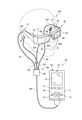
HMD100(表示装置)は、使用者の頭部に装着された状態で使用者に虚像を視認させる画像表示部20(表示部)と、画像表示部20を制御する制御装置10と、を備えている。制御装置10は、使用者がHMD100を操作するコントローラーとしても機能する。
[First Embodiment]
FIG. 1 is an explanatory diagram showing an external configuration of an HMD (Head Mounted Display) 100 according to a first embodiment to which the present invention is applied.
The HMD 100 (display device) includes an image display unit 20 (display unit) that allows a user to visually recognize a virtual image while being mounted on the user's head, and a control device 10 that controls the image display unit 20. Yes. The control device 10 also functions as a controller for the user to operate the HMD 100.

画像表示部20は、使用者の頭部に装着される装着体であり、本実施形態では眼鏡形状を有する。画像表示部20は、右保持部21と、右表示駆動部22と、左保持部23と、左表示駆動部24と、右光学像表示部26と、左光学像表示部28と、カメラ61(撮像部)と、マイク63とを備える。右光学像表示部26及び左光学像表示部28は、それぞれ、使用者が画像表示部20を装着した際に使用者の右及び左の眼前に位置するように配置されている。右光学像表示部26の一端と左光学像表示部28の一端とは、使用者が画像表示部20を装着した際の使用者の眉間に対応する位置で、互いに連結されている。   The image display unit 20 is a wearing body that is worn on the user's head, and has a glasses shape in the present embodiment. The image display unit 20 includes a right holding unit 21, a right display driving unit 22, a left holding unit 23, a left display driving unit 24, a right optical image display unit 26, a left optical image display unit 28, and a camera 61. (Imaging part) and a microphone 63 are provided. The right optical image display unit 26 and the left optical image display unit 28 are arranged so as to be positioned in front of the right and left eyes of the user when the user wears the image display unit 20, respectively. One end of the right optical image display unit 26 and one end of the left optical image display unit 28 are connected to each other at a position corresponding to the eyebrow of the user when the user wears the image display unit 20.

右保持部21は、右光学像表示部26の他端である端部ERから、使用者が画像表示部20を装着した際の使用者の側頭部に対応する位置にかけて、延伸して設けられた部材である。同様に、左保持部23は、左光学像表示部28の他端である端部ELから、使用者が画像表示部20を装着した際の使用者の側頭部に対応する位置にかけて、延伸して設けられた部材である。右保持部21及び左保持部23は、眼鏡のテンプル(つる)のようにして、使用者の頭部に画像表示部20を保持する。   The right holding unit 21 extends from the end ER which is the other end of the right optical image display unit 26 to a position corresponding to the user's temporal region when the user wears the image display unit 20. It is a member. Similarly, the left holding unit 23 extends from the end EL which is the other end of the left optical image display unit 28 to a position corresponding to the user's temporal region when the user wears the image display unit 20. It is a member provided. The right holding unit 21 and the left holding unit 23 hold the image display unit 20 on the user's head like a temple of glasses.

右表示駆動部22と左表示駆動部24とは、使用者が画像表示部20を装着した際の使用者の頭部に対向する側に配置されている。なお、右表示駆動部22及び左表示駆動部24を総称して単に「表示駆動部」とも呼び、右光学像表示部26及び左光学像表示部28を総称して単に「光学像表示部」とも呼ぶ。   The right display drive unit 22 and the left display drive unit 24 are disposed on the side facing the user's head when the user wears the image display unit 20. The right display drive unit 22 and the left display drive unit 24 are collectively referred to simply as “display drive unit”, and the right optical image display unit 26 and the left optical image display unit 28 are simply referred to as “optical image display unit”. Also called.

表示駆動部22,24は、図2を参照して後述する液晶ディスプレイ241,242(Liquid Crystal Display、以下「LCD241,242」と呼ぶ)、投写光学系251,252等を含む。
右光学像表示部26及び左光学像表示部28は、導光板261,262(図2)と、調光板20Aとを備える。導光板261,262は、光透過性の樹脂等によって形成され、表示駆動部22,24が出力する画像光を、使用者の眼に導く。調光板20Aは、薄板状の光学素子であり、使用者の眼の側とは反対の側である画像表示部20の表側を覆うように配置される。調光板20Aは、光透過性がほぼ無いもの、透明に近いもの、光量を減衰させて光を透過するもの、特定の波長の光を減衰又は反射するもの等、種々のものを用いることができる。調光板20Aの光学特性(光透過率など)を適宜選択することにより、外部から右光学像表示部26及び左光学像表示部28に入射する外光量を調整して、虚像の視認のしやすさを調整できる。本実施形態では、HMD100は、少なくとも、HMD100を装着した使用者が外の景色を視認できる程度の光透過性を有する調光板20Aを用いる。調光板20Aは、右導光板261及び左導光板262を保護し、右導光板261及び左導光板262の損傷や汚れの付着等を抑制する。
The display drive units 22 and 24 include liquid crystal displays 241 and 242 (hereinafter referred to as “LCDs 241 and 242”), projection optical systems 251 and 252, which will be described later with reference to FIG.
The right optical image display unit 26 and the left optical image display unit 28 include light guide plates 261 and 262 (FIG. 2) and a light control plate 20A. The light guide plates 261 and 262 are formed of a light transmissive resin or the like, and guide the image light output from the display driving units 22 and 24 to the user's eyes. The light control plate 20A is a thin plate-like optical element, and is disposed so as to cover the front side of the image display unit 20 which is the side opposite to the user's eye side. As the light control plate 20A, various materials such as a material that has almost no light transmission, a material that is nearly transparent, a material that attenuates the amount of light and transmits light, and a material that attenuates or reflects light of a specific wavelength may be used. it can. By appropriately selecting the optical characteristics (light transmittance, etc.) of the light control plate 20A, the external light amount incident on the right optical image display unit 26 and the left optical image display unit 28 from the outside is adjusted to visually recognize the virtual image. You can adjust the ease. In the present embodiment, the HMD 100 uses at least a light control plate 20 </ b> A having such a light transmittance that a user wearing the HMD 100 can visually recognize an outside scene. The light control plate 20A protects the right light guide plate 261 and the left light guide plate 262, and suppresses damage to the right light guide plate 261 and the left light guide plate 262, adhesion of dirt, and the like.

調光板20Aは、右光学像表示部26及び左光学像表示部28に対し着脱可能としてもよい。この場合、複数種類の調光板20Aを交換して装着可能としてもよい。例えば、可視光線の透過度が異なる複数種類の調光板から1種類を選択して画像表示部20に装着可能な構成としてもよい。また、透過する光の色(可視光領域における透過スペクトル)が異なる複数種類の調光板から選択してもよい。また、画像表示部20に調光板20Aを装着しない状態であっても使用可能な構成としてもよい。   The light control plate 20A may be detachable from the right optical image display unit 26 and the left optical image display unit 28. In this case, a plurality of types of light control plates 20A may be exchanged and mounted. For example, a configuration may be adopted in which one type can be selected from a plurality of types of light control plates having different visible light transmittances and attached to the image display unit 20. Moreover, you may select from the multiple types of light control board from which the color (transmission spectrum in visible region) of the light to permeate | transmits differs. The image display unit 20 may be configured to be usable even when the light control plate 20A is not attached.

カメラ61は、右光学像表示部26と左光学像表示部28との境目部分に配置される。使用者が画像表示部20を装着した状態で、カメラ61の位置は、水平方向においては使用者の両眼のほぼ中間であり、鉛直方向においては使用者の両眼より上である。カメラ61は、CCDやCMOS等の撮像素子及び撮像レンズ等を備えるデジタルカメラであり、単眼カメラであってもステレオカメラであってもよい。
カメラ61は、HMD100の表側方向、換言すれば、HMD100を装着した状態における使用者の視界方向の少なくとも一部の外景を撮像する。カメラ61の画角の広さは適宜設定可能であるが、カメラ61の撮像範囲が、使用者が右光学像表示部26、左光学像表示部28を通して視認する外界に重なることが好ましい。さらに、調光板20Aを通した使用者の視界の全体を撮像できるようにカメラ61の撮像範囲が設定されているとより好ましい。
The camera 61 is disposed at the boundary between the right optical image display unit 26 and the left optical image display unit 28. In a state where the user wears the image display unit 20, the position of the camera 61 is substantially in the middle of both eyes of the user in the horizontal direction and above the eyes of the user in the vertical direction. The camera 61 is a digital camera that includes an imaging element such as a CCD or CMOS, an imaging lens, and the like, and may be a monocular camera or a stereo camera.
The camera 61 images at least a part of the outside scene in the front side direction of the HMD 100, in other words, the user's view direction when the HMD 100 is worn. Although the angle of view of the camera 61 can be set as appropriate, it is preferable that the imaging range of the camera 61 overlaps with the outside world visually recognized by the user through the right optical image display unit 26 and the left optical image display unit 28. Furthermore, it is more preferable that the imaging range of the camera 61 is set so that the entire field of view of the user through the light control plate 20A can be imaged.

また、フレーム2には、光を検出する外光センサー68(光検出部)が配置される。外光センサー68は、光を受光し、受光した光量または受光した光の強度に応じた検出値を出力する環境光センサー(Ambient Light Sensor)である。
外光センサー68はカメラ61の近傍に配置され、カメラ61の画角を含む方向から外光センサー68に向けて照射される光を受光し、光量を検出する。また、外光センサー68は画像表示部20に隣接して設けられるので、画像表示部20に対して外部から照射または入射する光とほぼ同じ方向からの光を受光する。これにより、外光センサー68は、画像表示部20を透過して使用者の眼に入射する光と同じ方向からの光を受光するので、使用者の眼に入射する外光を受光すると見なすことができる。
In addition, an external light sensor 68 (light detection unit) that detects light is disposed in the frame 2. The external light sensor 68 is an ambient light sensor that receives light and outputs a detection value corresponding to the received light quantity or the intensity of the received light.
The external light sensor 68 is disposed in the vicinity of the camera 61, receives light emitted from the direction including the angle of view of the camera 61 toward the external light sensor 68, and detects the amount of light. In addition, since the external light sensor 68 is provided adjacent to the image display unit 20, the external light sensor 68 receives light from substantially the same direction as the light irradiated or incident on the image display unit 20 from the outside. Accordingly, the external light sensor 68 receives light from the same direction as the light that is transmitted through the image display unit 20 and is incident on the user's eyes, and is thus regarded as receiving external light that is incident on the user's eyes. Can do.

ここで、外光とは、右表示駆動部22及び左表示駆動部24が発する光のほかに、使用者の眼に入射する光をいう。具体的には、使用者の眼に入射する光のうち、図2に示す右表示駆動部22及び左表示駆動部24とは異なる光源が発する光を指し、光源から直接入射する直接光と反射光とのどちらを含んでもよい。
外光センサー68は図1に示したように画像表示部20の外から照射される光を受光し、特に、使用者の前方から照射される光を受光しやすい向きに設けられる。使用者の眼に実際に入射する外光は、右光学像表示部26、左光学像表示部28及び調光板20Aを透過した光を含むが、外光センサー68が、右光学像表示部26または左光学像表示部28を透過した光そのものを受光する構成でなくてもよい。つまり、外光センサー68の検出値が、使用者の眼に入射する外光の光量または強度の指標として利用可能であれば、本発明を実施できる。例えば、図1に示すように、使用者の眼に入射する外光と概ね同じ方向から画像表示部20の外面に照射される光の一部を、外光センサー68が受光できる構成が挙げられる。また、本実施形態では、一つの外光センサー68をフレーム2に設ける構成を例に挙げるが、複数の外光センサー68を設けることも可能である。また、外光センサー68の位置は、図1に示すようにフレーム2の幅方向における中央とする他、端部ERや端部ELに設けてもよい。
この構成により、外光センサー68が検出する光は、使用者が右導光板261、左導光板262を透過して視認する外景方向の外光とみなすことができる。言い換えれば、外光センサー68は、図2に示す画像光Lの背景光として使用者の眼に入射する外光OLを検出する。
Here, outside light refers to light incident on the user's eyes in addition to the light emitted by the right display drive unit 22 and the left display drive unit 24. Specifically, it refers to light emitted from a light source different from the right display drive unit 22 and the left display drive unit 24 shown in FIG. 2 among light incident on the user's eyes, and direct light and reflection directly incident from the light source. Either light or light may be included.
As shown in FIG. 1, the external light sensor 68 receives light emitted from the outside of the image display unit 20, and is particularly provided in a direction in which light emitted from the front of the user is easily received. The external light that actually enters the user's eyes includes light that has passed through the right optical image display unit 26, the left optical image display unit 28, and the dimming plate 20A, but the external light sensor 68 has a right optical image display unit. 26 or the left optical image display unit 28 may not be configured to receive the light itself. That is, the present invention can be implemented if the detection value of the external light sensor 68 can be used as an index of the amount or intensity of external light incident on the user's eyes. For example, as shown in FIG. 1, there is a configuration in which the external light sensor 68 can receive a part of light irradiated on the outer surface of the image display unit 20 from substantially the same direction as the external light incident on the user's eyes. . In the present embodiment, a configuration in which one external light sensor 68 is provided in the frame 2 is taken as an example, but a plurality of external light sensors 68 may be provided. Further, the position of the outside light sensor 68 may be provided at the end ER or the end EL in addition to the center in the width direction of the frame 2 as shown in FIG.
With this configuration, the light detected by the external light sensor 68 can be regarded as external light in the outside scene direction that is viewed by the user through the right light guide plate 261 and the left light guide plate 262. In other words, the external light sensor 68 detects the external light OL incident on the user's eyes as the background light of the image light L shown in FIG.

図2は、画像表示部20が備える光学系の構成を示す要部平面図である。図2には説明のため使用者の左眼LE及び右眼REを図示する。
左表示駆動部24は、LED等の光源と拡散板とを有する左バックライト222を備える。また、左表示駆動部24は、左バックライト222の拡散板で拡散された光の光路上に配置される透過型の左LCD242、および、左LCD242を透過した画像光Lを導くレンズ群等を備えた左投写光学系252を備える。左LCD242は、複数の画素をマトリクス状に配置した透過型液晶パネルである。
FIG. 2 is a principal plan view showing the configuration of the optical system provided in the image display unit 20. FIG. 2 shows the user's left eye LE and right eye RE for explanation.
The left display driving unit 24 includes a left backlight 222 having a light source such as an LED and a diffusion plate. The left display driving unit 24 includes a transmissive left LCD 242 disposed on the optical path of light diffused by the diffusion plate of the left backlight 222, a lens group that guides the image light L transmitted through the left LCD 242, and the like. The left projection optical system 252 is provided. The left LCD 242 is a transmissive liquid crystal panel in which a plurality of pixels are arranged in a matrix.

左投写光学系252は、左LCD242から射出された画像光Lを平行状態の光束にするコリメートレンズを有する。コリメートレンズにより平行状態の光束にされた画像光Lは、左導光板262(光学素子)に入射される。左導光板262は、画像光Lを反射する複数の反射面が形成されたプリズムであり、画像光Lは、左導光板262の内部において複数回の反射を経て左眼LE側に導かれる。左導光板262には、左眼LEの眼前に位置するハーフミラー262A(反射面)が形成される。
ハーフミラー262Aで反射した画像光Lは左眼LEに向けて左光学像表示部28から射出され、この画像光Lが左眼LEの網膜に像を結び、使用者に画像を視認させる。
The left projection optical system 252 includes a collimator lens that converts the image light L emitted from the left LCD 242 into a parallel light beam. The image light L converted into a parallel light beam by the collimating lens is incident on the left light guide plate 262 (optical element). The left light guide plate 262 is a prism formed with a plurality of reflecting surfaces that reflect the image light L, and the image light L is guided to the left eye LE side through a plurality of reflections inside the left light guide plate 262. The left light guide plate 262 is formed with a half mirror 262A (reflection surface) positioned in front of the left eye LE.
The image light L reflected by the half mirror 262A is emitted from the left optical image display unit 28 toward the left eye LE, and this image light L forms an image on the retina of the left eye LE so that the user can visually recognize the image.

右表示駆動部22は、左表示駆動部24と左右対称に構成される。右表示駆動部22は、LED等の光源と拡散板とを有する右バックライト221を備える。また、右表示駆動部22は、右バックライト221の拡散板で拡散された光の光路上に配置される透過型の右LCD241、および、右LCD241を透過した画像光Lを導くレンズ群等を備えた右投写光学系251を備える。右LCD241は、複数の画素をマトリクス状に配置した透過型液晶パネルである。   The right display driving unit 22 is configured to be symmetrical with the left display driving unit 24. The right display driving unit 22 includes a right backlight 221 having a light source such as an LED and a diffusion plate. The right display driving unit 22 includes a transmissive right LCD 241 disposed on the optical path of light diffused by the diffusion plate of the right backlight 221, a lens group that guides the image light L transmitted through the right LCD 241, and the like. A right projection optical system 251 is provided. The right LCD 241 is a transmissive liquid crystal panel in which a plurality of pixels are arranged in a matrix.

右投写光学系251は、右LCD241から射出された画像光Lを平行状態の光束にするコリメートレンズを有する。コリメートレンズにより平行状態の光束にされた画像光Lは、右導光板261(光学素子)に入射される。右導光板261は、画像光Lを反射する複数の反射面が形成されたプリズムであり、画像光Lは、右導光板261の内部において複数回の反射を経て右眼RE側に導かれる。右導光板261には、右眼REの眼前に位置するハーフミラー261A(反射面)が形成される。
ハーフミラー261Aで反射した画像光Lは右眼REに向けて右光学像表示部26から射出され、この画像光Lが右眼REの網膜に像を結び、使用者に画像を視認させる。
The right projection optical system 251 has a collimator lens that converts the image light L emitted from the right LCD 241 into a light beam in a parallel state. The image light L converted into a parallel light beam by the collimating lens is incident on the right light guide plate 261 (optical element). The right light guide plate 261 is a prism formed with a plurality of reflecting surfaces that reflect the image light L, and the image light L is guided to the right eye RE side through a plurality of reflections inside the right light guide plate 261. The right light guide plate 261 is formed with a half mirror 261A (reflection surface) located in front of the right eye RE.
The image light L reflected by the half mirror 261A is emitted from the right optical image display unit 26 toward the right eye RE, and this image light L forms an image on the retina of the right eye RE to make the user visually recognize the image.

使用者の右眼REには、ハーフミラー261Aで反射した画像光Lと、調光板20Aを透過した外光OLとが入射する。左眼LEには、ハーフミラー262Aで反射した画像光Lと、調光板20Aを透過した外光OLとが入射する。このように、HMD100は、内部で処理した画像の画像光Lと外光OLとを重ねて使用者の眼に入射させ、使用者にとっては、調光板20Aを透かして外景が見え、この外景に重ねて、画像光Lによる画像が視認される。このように、HMD100は、シースルー型の表示装置として機能する。   The image light L reflected by the half mirror 261A and the external light OL transmitted through the light control plate 20A are incident on the right eye RE of the user. The image light L reflected by the half mirror 262A and the external light OL transmitted through the light control plate 20A are incident on the left eye LE. In this way, the HMD 100 superimposes the image light L of the internally processed image and the external light OL on the user's eyes and allows the user to see the external scene through the light control plate 20A. The image by the image light L is visually recognized. As described above, the HMD 100 functions as a see-through display device.

なお、左投写光学系252と左導光板262とを総称して「左導光部」とも呼び、右投写光学系251と右導光板261とを総称して「右導光部」と呼ぶ。右導光部及び左導光部の構成は上記の例に限定されず、画像光を用いて使用者の眼前に虚像を形成する限りにおいて任意の方式を用いることができ、例えば、回折格子を用いても良いし、半透過反射膜を用いても良い。   The left projection optical system 252 and the left light guide plate 262 are collectively referred to as “left light guide unit”, and the right projection optical system 251 and the right light guide plate 261 are collectively referred to as “right light guide unit”. The configuration of the right light guide and the left light guide is not limited to the above example, and any method can be used as long as a virtual image is formed in front of the user's eyes using image light. It may be used, or a semi-transmissive reflective film may be used.

画像表示部20(図1)は、制御装置10に接続部40を介して接続する。接続部40は、制御装置10に接続される本体コード48、右コード42、左コード44、及び、連結部材46を備えるハーネスである。右コード42及び左コード44は、本体コード48が2本に分岐し、右コード42は右保持部21の延伸方向の先端部APから右保持部21の筐体内に挿入され、右表示駆動部22に接続される。同様に、左コード44は、左保持部23の延伸方向の先端部APから左保持部23の筐体内に挿入され、左表示駆動部24に接続される。右コード42、左コード44、及び、本体コード48は、デジタルデータを伝送可能なものであればよく、例えば金属ケーブルや光ファイバーで構成できる。また、右コード42と左コード44とを一本のコードにまとめた構成としてもよい。   The image display unit 20 (FIG. 1) is connected to the control device 10 via the connection unit 40. The connection unit 40 is a harness including a body cord 48, a right cord 42, a left cord 44, and a connecting member 46 that are connected to the control device 10. The right cord 42 and the left cord 44 are branched into two main body cords 48, and the right cord 42 is inserted into the housing of the right holding portion 21 from the distal end portion AP in the extending direction of the right holding portion 21, and the right display driving portion. 22 is connected. Similarly, the left cord 44 is inserted into the housing of the left holding unit 23 from the distal end AP in the extending direction of the left holding unit 23 and connected to the left display driving unit 24. The right cord 42, the left cord 44, and the main body cord 48 only need to be capable of transmitting digital data, and can be constituted by, for example, a metal cable or an optical fiber. Further, the right cord 42 and the left cord 44 may be combined into a single cord.

連結部材46は、本体コード48と、右コード42及び左コード44との分岐点に設けられ、イヤホンプラグ30を接続するためのジャックを有する。イヤホンプラグ30からは、右イヤホン32及び左イヤホン34が延伸する。イヤホンプラグ30の近傍にはマイク63が設けられる。イヤホンプラグ30からマイク63までは一本のコードにまとめられ、マイク63からコードが分岐して、右イヤホン32と左イヤホン34のそれぞれに繋がる。   The connecting member 46 is provided at a branch point between the main body cord 48, the right cord 42 and the left cord 44, and has a jack for connecting the earphone plug 30. A right earphone 32 and a left earphone 34 extend from the earphone plug 30. A microphone 63 is provided in the vicinity of the earphone plug 30. The earphone plug 30 to the microphone 63 are combined into one cord, and the cord branches from the microphone 63 and is connected to each of the right earphone 32 and the left earphone 34.

マイク63は、例えば図1に示すように、マイク63の集音部が使用者の視線方向を向くように配置され、音声を集音して、音声信号を出力する。マイク63は、例えばモノラルマイクであってもステレオマイクであってもよく、指向性を有するマイクであってもよいし、無指向性のマイクであってもよい。   For example, as shown in FIG. 1, the microphone 63 is arranged such that the sound collection unit of the microphone 63 faces the user's line of sight, collects sound, and outputs a sound signal. For example, the microphone 63 may be a monaural microphone or a stereo microphone, may be a directional microphone, or may be an omnidirectional microphone.

画像表示部20と制御装置10とは、接続部40を介して各種信号を伝送する。本体コード48の連結部材46とは反対側の端部、及び、制御装置10には、互いに嵌合するコネクター(図示略)が設けられる。本体コード48のコネクターと制御装置10のコネクターとを嵌合し、或いは、この嵌合を外すことで、制御装置10と画像表示部20とを接離できる。   The image display unit 20 and the control device 10 transmit various signals via the connection unit 40. The end of the main body cord 48 opposite to the connecting member 46 and the control device 10 are provided with connectors (not shown) that fit together. By fitting the connector of the main body cord 48 and the connector of the control device 10 or removing this fitting, the control device 10 and the image display unit 20 can be contacted and separated.

制御装置10は、画像表示部20の本体とは別体となる箱形の本体を有し、HMD100を制御する。制御装置10は、決定キー11、点灯部12、表示切替キー13、輝度切替キー15、方向キー16、メニューキー17、及び電源スイッチ18を含むスイッチ類を備える。また、制御装置10は、使用者が手指で操作するトラックパッド14を備える。   The control device 10 has a box-shaped main body that is separate from the main body of the image display unit 20, and controls the HMD 100. The control device 10 includes switches including an enter key 11, a lighting unit 12, a display switching key 13, a luminance switching key 15, a direction key 16, a menu key 17, and a power switch 18. In addition, the control device 10 includes a track pad 14 that is operated by a user with fingers.

決定キー11は、押下操作を検出して、制御装置10で操作された内容を決定する信号を出力する。点灯部12は、LED(Light Emitting Diode)等の光源を備え、光源の点灯状態により、HMD100の動作状態(例えば、電源のON/OFF)を通知する。表示切替キー13は、押下操作に応じて、例えば、画像の表示モードの切り替えを指示する信号を出力する。   The determination key 11 detects a pressing operation and outputs a signal for determining the content operated by the control device 10. The lighting unit 12 includes a light source such as an LED (Light Emitting Diode), and notifies the operation state (for example, power ON / OFF) of the HMD 100 according to the lighting state of the light source. The display switching key 13 outputs, for example, a signal instructing switching of the image display mode in response to the pressing operation.

トラックパッド14は、接触操作を検出する操作面を有し、操作面に対する操作に応じて操作信号を出力する。操作面における検出方式は限定されず、静電式、圧力検出式、光学式等を採用できる。輝度切替キー15は、押下操作に応じて画像表示部20の輝度の増減を指示する信号を出力する。方向キー16は、上下左右方向に対応するキーへの押下操作に応じて操作信号を出力する。電源スイッチ18は、HMD100の電源オン/オフを切り替えるスイッチである。   The track pad 14 has an operation surface for detecting a contact operation, and outputs an operation signal according to an operation on the operation surface. The detection method on the operation surface is not limited, and an electrostatic method, a pressure detection method, an optical method, or the like can be adopted. The luminance switching key 15 outputs a signal instructing increase / decrease of the luminance of the image display unit 20 in response to the pressing operation. The direction key 16 outputs an operation signal in response to a pressing operation on a key corresponding to the up / down / left / right direction. The power switch 18 is a switch for switching on / off the power of the HMD 100.

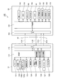
図3は、HMD100を構成する各部の機能ブロック図である。
制御装置10は、制御装置10及び画像表示部20を制御する制御部110(第2制御部)を備える。制御部110は、例えばマイクロプロセッサーで構成され、制御部110が処理するデータ等を一時的に記憶するメモリー121、及び、制御部110が処理するデータ等を不揮発的に記憶する記憶部122に接続される。メモリー121及び記憶部122はいずれも半導体素子により構成され、データバスを介して制御部110に接続する。
FIG. 3 is a functional block diagram of each part constituting the HMD 100.
The control device 10 includes a control unit 110 (second control unit) that controls the control device 10 and the image display unit 20. The control unit 110 is composed of, for example, a microprocessor, and is connected to a memory 121 that temporarily stores data processed by the control unit 110 and a storage unit 122 that stores data processed by the control unit 110 in a nonvolatile manner. Is done. Both the memory 121 and the storage unit 122 are configured by semiconductor elements, and are connected to the control unit 110 via a data bus.

制御部110には、電源制御部123、UI(ユーザーインターフェイス)制御部124、無線I/F(インターフェイス)制御部125、音声制御部126、センサーIC127、及び、外部I/F(インターフェイス)部128が接続される。
HMD100は、電源として一次電池または二次電池を備え、電源制御部123は、これら電池に接続されるICで構成される。電源制御部123は、制御部110の制御に従って電池の残容量の検出を行い、検出値のデータ、または残容量が設定値以下となったことを示すデータを制御部110に出力する。
The control unit 110 includes a power supply control unit 123, a UI (user interface) control unit 124, a wireless I / F (interface) control unit 125, an audio control unit 126, a sensor IC 127, and an external I / F (interface) unit 128. Is connected.
The HMD 100 includes a primary battery or a secondary battery as a power source, and the power control unit 123 includes an IC connected to these batteries. The power supply control unit 123 detects the remaining capacity of the battery according to the control of the control unit 110, and outputs detection value data or data indicating that the remaining capacity is equal to or less than the set value to the control unit 110.

UI制御部124は、図1に示した決定キー11、表示切替キー13、トラックパッド14、輝度切替キー15、方向キー16、及びメニューキー17の各操作部、点灯部12、及び、トラックパッド14が接続されるICである。上記各操作部は入力部として機能し、点灯部12及びトラックパッド14は出力部として機能し、HMD100のユーザーインターフェイスを構成する。UI制御部124は、上記操作部における操作を検出して、操作に対応する操作データを制御部110に出力する。また、UI制御部124は、制御部110の制御に従って、点灯部12の点灯/消灯、及びトラックパッド14における表示を行う。   The UI control unit 124 includes the determination key 11, the display switching key 13, the track pad 14, the luminance switching key 15, the direction key 16, and the menu key 17 shown in FIG. 1, the lighting unit 12, and the track pad. 14 is an IC to be connected. Each of the operation units functions as an input unit, and the lighting unit 12 and the track pad 14 function as an output unit, and constitute a user interface of the HMD 100. The UI control unit 124 detects an operation in the operation unit, and outputs operation data corresponding to the operation to the control unit 110. Further, the UI control unit 124 performs lighting / extinguishing of the lighting unit 12 and display on the track pad 14 according to the control of the control unit 110.

無線I/F制御部125は、無線通信インターフェイス(図示略)に接続される制御ICであり、制御部110の制御に従って、上記無線通信インターフェイスによる通信を実行する。制御装置10が備える無線通信インターフェイスは、例えば、無線LAN(WiFi(登録商標))、Miracast(登録商標)、Bluetooth(登録商標)等の規格に準じた無線データ通信を実行する。
音声制御部126は、右イヤホン32、左イヤホン34、及びマイク63に接続され、A/D(アナログ/ディジタル)コンバーターやアンプ等を備えるICである。音声制御部126は、制御部110から入力される音声データに基づき右イヤホン32及び左イヤホン34から音声を出力させる。また、音声制御部126は、マイク63が集音する音声に基づき音声データを生成して制御部110に出力する。
The wireless I / F control unit 125 is a control IC connected to a wireless communication interface (not shown), and executes communication using the wireless communication interface according to the control of the control unit 110. The wireless communication interface included in the control device 10 performs wireless data communication conforming to a standard such as a wireless LAN (WiFi (registered trademark)), Miracast (registered trademark), Bluetooth (registered trademark), or the like.
The audio control unit 126 is an IC that is connected to the right earphone 32, the left earphone 34, and the microphone 63 and includes an A / D (analog / digital) converter, an amplifier, and the like. The sound control unit 126 outputs sound from the right earphone 32 and the left earphone 34 based on the sound data input from the control unit 110. In addition, the voice control unit 126 generates voice data based on the voice collected by the microphone 63 and outputs the voice data to the control unit 110.

センサーIC127は、例えば、3軸加速度センサー、3軸ジャイロセンサー、及び3軸地磁気センサーを備え、例えば上記センサーを具備する1つのICで構成される。センサーIC127は、制御部110の制御に従って検出を実行し、各センサーの検出値を示すデータを制御部110に出力する。センサーIC127が備えるセンサーの数や種類は制限されず、外光センサー、温度センサー、圧力センサー等を備えてもよい。   The sensor IC 127 includes, for example, a three-axis acceleration sensor, a three-axis gyro sensor, and a three-axis geomagnetic sensor, and includes, for example, one IC including the sensor. The sensor IC 127 performs detection according to the control of the control unit 110 and outputs data indicating the detection value of each sensor to the control unit 110. The number and types of sensors provided in the sensor IC 127 are not limited, and an external light sensor, a temperature sensor, a pressure sensor, and the like may be provided.

外部I/F部128は、HMD100を外部機器に接続するインターフェイスである。例えば、USBインターフェイス、マイクロUSBインターフェイス、メモリーカード用インターフェイス等の有線接続に対応したインターフェイスを用いることができ、無線通信インターフェイスで構成してもよい。外部I/F部128には、HMD100に対してコンテンツを供給する種々の外部機器を接続できる。これらの外部機器は、HMD100に画像を供給する画像供給装置ということもでき、例えば、パーソナルコンピューター(PC)、携帯電話端末、携帯型ゲーム機等が用いられる。また、外部I/F部128は、右イヤホン32、左イヤホン34及びマイク63に繋がる端子を設けてもよく、この場合、音声制御部126が処理するアナログ音声信号は外部I/F部128を介して入出力される。   The external I / F unit 128 is an interface that connects the HMD 100 to an external device. For example, an interface corresponding to a wired connection such as a USB interface, a micro USB interface, a memory card interface, or the like can be used, and a wireless communication interface may be used. Various external devices that supply content to the HMD 100 can be connected to the external I / F unit 128. These external devices can also be referred to as image supply devices that supply images to the HMD 100. For example, a personal computer (PC), a mobile phone terminal, a portable game machine, or the like is used. In addition, the external I / F unit 128 may be provided with terminals connected to the right earphone 32, the left earphone 34, and the microphone 63. In this case, the analog audio signal processed by the audio control unit 126 passes through the external I / F unit 128. Input and output.

制御部110には、I/F(インターフェイス)部115が接続される。I/F部115は接続部40に一端に接続するコネクター等を備えたインターフェイスであり、接続部40の他端は画像表示部20のI/F部155に接続される。
制御部110は、接続部40を介して、画像表示部20が備えるサブ制御部150とデータ通信を実行する。
An I / F (interface) unit 115 is connected to the control unit 110. The I / F unit 115 is an interface including a connector connected to one end of the connection unit 40, and the other end of the connection unit 40 is connected to the I / F unit 155 of the image display unit 20.
The control unit 110 performs data communication with the sub-control unit 150 included in the image display unit 20 via the connection unit 40.

制御部110は、内蔵するROMに記憶するプログラムを実行して、HMD100の各部を制御する。制御部110は、センサーIC127から入力されるデータに基づきセンサーの検出値を取得して、メモリー121に記憶する。このとき、制御部110は、センサーの検出値に対応付けて、検出値を取得した時刻を示すタイムスタンプ情報を付加して記憶する。   The control unit 110 executes a program stored in the built-in ROM and controls each unit of the HMD 100. The control unit 110 acquires the detection value of the sensor based on the data input from the sensor IC 127 and stores it in the memory 121. At this time, the control unit 110 adds and stores time stamp information indicating the time when the detection value is acquired in association with the detection value of the sensor.

また、制御部110は、接続部40を介して、画像表示部20が備えるセンサー(外光センサー68、9軸センサー162、及び、GPS163)の検出値を示すデータを受信する。制御部110は、受信したデータをメモリー121に記憶する。制御部110が受信するデータは、サブ制御部150が付加したタイムスタンプ情報を含む。制御部110は、上記のようにセンサーIC127の検出値に付加するタイムスタンプ情報を、サブ制御部150が付加したタイムスタンプ情報と区別できる態様で付加し、メモリー121に記憶する。メモリー121には、センサーの検出値が、データの属性の1つとしてタイムスタンプ情報が付加されたデータ形式で記憶される。ここで、制御部110は、センサーの検出値のデータを、記憶部122に記憶してもよい。   In addition, the control unit 110 receives data indicating detection values of sensors (external light sensor 68, 9-axis sensor 162, and GPS 163) included in the image display unit 20 via the connection unit 40. The control unit 110 stores the received data in the memory 121. The data received by the control unit 110 includes time stamp information added by the sub-control unit 150. The control unit 110 adds the time stamp information added to the detection value of the sensor IC 127 as described above in a manner that can be distinguished from the time stamp information added by the sub control unit 150 and stores the time stamp information in the memory 121. The memory 121 stores the sensor detection value in a data format to which time stamp information is added as one of the data attributes. Here, the control unit 110 may store the sensor detection value data in the storage unit 122.

制御部110は、外部I/F部128または無線I/F制御部125により接続する外部機器から、コンテンツのデータを受信して、記憶部122に記憶する。コンテンツのデータは、画像表示部20で表示するテキストや画像等のデータであり、右イヤホン32及び左イヤホン34で出力する音声のデータを含んでもよい。制御部110は、HMD100を制御してコンテンツを再生する。具体的には、制御部110は、コンテンツの表示用のデータをサブ制御部150に送信して表示を実行させ、コンテンツの音声データを音声制御部126に出力して音声を出力させる。また、外部機器から受信するコンテンツのデータが、再生に関する条件を示すデータを含む場合、制御部110は、この条件に従ってコンテンツを再生する。例えば、画像表示部20において検出される位置や傾き等のセンサーの検出値が、条件に該当する場合に、検出値に対応するテキストや画像を表示させる。   The control unit 110 receives content data from an external device connected by the external I / F unit 128 or the wireless I / F control unit 125 and stores the data in the storage unit 122. The content data is data such as text and images displayed on the image display unit 20, and may include audio data output from the right earphone 32 and the left earphone 34. The control unit 110 controls the HMD 100 to reproduce content. Specifically, the control unit 110 transmits content display data to the sub-control unit 150 to execute display, and outputs audio data of the content to the audio control unit 126 to output audio. When the content data received from the external device includes data indicating a condition related to reproduction, the control unit 110 reproduces the content according to the condition. For example, when a detection value of a sensor such as a position or inclination detected in the image display unit 20 satisfies a condition, a text or an image corresponding to the detection value is displayed.

画像表示部20は、制御部110と通信を実行し、画像表示部20の各部を制御するサブ制御部150を備える。サブ制御部150は、例えばマイクロプロセッサーで構成され、I/F部155により接続部40に接続され、接続部40を介して制御部110との間でデータ通信を実行する。
サブ制御部150には、外光センサー68、9軸センサー162、及び、GPS163のセンサー類が接続される。外光センサー68は、上述したように環境光センサー(ALS)のIC、又は、環境光センサーを含む複数のセンサーやセンサーの周辺回路をユニット化したICである。9軸センサー162は、3軸加速度センサー、3軸ジャイロセンサー、及び、3軸地磁気センサーを備えるICである。
The image display unit 20 includes a sub-control unit 150 that performs communication with the control unit 110 and controls each unit of the image display unit 20. The sub control unit 150 is configured by, for example, a microprocessor, is connected to the connection unit 40 by the I / F unit 155, and executes data communication with the control unit 110 via the connection unit 40.
An external light sensor 68, a 9-axis sensor 162, and GPS 163 sensors are connected to the sub control unit 150. As described above, the ambient light sensor 68 is an IC of an ambient light sensor (ALS), or an IC in which a plurality of sensors including the ambient light sensor and peripheral circuits of the sensors are unitized. The 9-axis sensor 162 is an IC including a 3-axis acceleration sensor, a 3-axis gyro sensor, and a 3-axis geomagnetic sensor.

外光センサー68は、光を受光して、複数の異なる波長域(周波数帯)における光量または強度を検出するカラーセンサーである。本実施形態では、外光センサー68はRGBカラーセンサーが採用される。外光センサー68の周波数感度特性は、R(赤)、G(緑)、B(青)の3色のそれぞれに対応するピーク周波数を有する。例えば、Rに対応する570〜700nmの波長域、Gに対応する450〜630nmの波長域、及び、Bに対応する400〜540nmの波長域のそれぞれの波長域の受光強度を検出する。この外光センサー68は、例えば、人間の視感効率に適合する特性を有することが好ましい。また、外光センサー68は、センサー(検出部)本体と、センサーの検出値をデジタルデータとして出力する回路部(検出回路部)とをモジュール化したセンサーモジュールであってもよい。   The external light sensor 68 is a color sensor that receives light and detects the light amount or intensity in a plurality of different wavelength ranges (frequency bands). In the present embodiment, the external light sensor 68 is an RGB color sensor. The frequency sensitivity characteristic of the external light sensor 68 has a peak frequency corresponding to each of the three colors R (red), G (green), and B (blue). For example, the received light intensity is detected in each of a wavelength range of 570 to 700 nm corresponding to R, a wavelength range of 450 to 630 nm corresponding to G, and a wavelength range of 400 to 540 nm corresponding to B. The outside light sensor 68 preferably has, for example, characteristics suitable for human visual efficiency. The external light sensor 68 may be a sensor module in which a sensor (detection unit) main body and a circuit unit (detection circuit unit) that outputs a detection value of the sensor as digital data are modularized.

外光センサー68は、サブ制御部150の制御により駆動され、例えばR、G、Bそれぞれの周波数帯における受光量または受光強度を示す検出値を、デジタルデータとして、サブ制御部150に出力する。   The external light sensor 68 is driven by the control of the sub-control unit 150, and outputs, for example, a detection value indicating the amount of received light or the received light intensity in each frequency band of R, G, B to the sub-control unit 150 as digital data.

9軸センサー162は、サブ制御部150の制御により駆動され、内蔵する各センサーの検出値を示すデータを、サブ制御部150に出力する。   The 9-axis sensor 162 is driven by the control of the sub-control unit 150 and outputs data indicating the detection value of each built-in sensor to the sub-control unit 150.

GPS163は、GPS衛星や屋内に設置される疑似GPS送信機(図示略)が送信する位置検出用の信号を受信して、画像表示部20の現在位置を算出し、算出したデータをサブ制御部150に出力する。GPS163は、位置検出用の信号を受信する受信機としての機能のみ有する構成としてもよく、この場合、GPS163が出力するデータに基づきサブ制御部150が現在位置を算出する処理を行えば良い。   The GPS 163 receives a position detection signal transmitted from a GPS satellite or a pseudo GPS transmitter (not shown) installed indoors, calculates the current position of the image display unit 20, and outputs the calculated data to the sub-control unit. 150. The GPS 163 may be configured to have only a function as a receiver that receives a signal for position detection. In this case, the sub-control unit 150 may perform a process of calculating the current position based on data output from the GPS 163.

EEPROM165(設定データ記憶部)は、サブ制御部150が実行する処理に関するデータ等を不揮発的に記憶する。
また、サブ制御部150にはカメラ61が接続され、サブ制御部150は、カメラ61を制御して撮像を実行させ、カメラ61の撮像画像データを制御部110に送信する。
The EEPROM 165 (setting data storage unit) stores data related to processing executed by the sub-control unit 150 in a nonvolatile manner.
In addition, the camera 61 is connected to the sub-control unit 150, and the sub-control unit 150 controls the camera 61 to execute imaging, and transmits captured image data of the camera 61 to the control unit 110.

サブ制御部150には、右LCD241を駆動して描画を行うLCD駆動部167、及び、左LCD242を駆動して描画を行うLCD駆動部168が接続される。サブ制御部150は、制御部110からコンテンツのデータを受信し、受信したデータに含まれるテキストや画像を表示する表示データを生成してLCD駆動部167、168に出力し、表示を実行させる。   Connected to the sub-control unit 150 are an LCD drive unit 167 that performs drawing by driving the right LCD 241 and an LCD drive unit 168 that performs drawing by driving the left LCD 242. The sub-control unit 150 receives content data from the control unit 110, generates display data for displaying text and images included in the received data, outputs the display data to the LCD driving units 167 and 168, and executes display.

また、サブ制御部150は、右バックライト221を駆動するバックライト駆動部169、及び、左バックライト222を駆動するバックライト駆動部170に接続される。サブ制御部150は、バックライト駆動部169、170に対し、PWM制御用のタイミングデータを含む制御データを出力する。バックライト駆動部169、170は、サブ制御部150から入力される制御データに基づき、右バックライト221、左バックライト222に駆動電圧とパルスを供給して、右バックライト221、左バックライト222を点灯させる。   The sub control unit 150 is connected to a backlight driving unit 169 that drives the right backlight 221 and a backlight driving unit 170 that drives the left backlight 222. The sub control unit 150 outputs control data including timing data for PWM control to the backlight driving units 169 and 170. The backlight driving units 169 and 170 supply driving voltages and pulses to the right backlight 221 and the left backlight 222 based on the control data input from the sub control unit 150, and the right backlight 221 and the left backlight 222. Lights up.

また、サブ制御部150は、バックライト駆動部169に出力するデータにより、バックライト駆動部169が右バックライト221に出力するパルスのパルス幅、或いは、デューティーを指定する。デューティーは、パルスのオン期間とオフ期間の比を指す。同様に、サブ制御部150は、バックライト駆動部170に出力するデータにより、バックライト駆動部170が左バックライト222に出力するパルスのパルス幅、或いは、デューティーを指定する。右バックライト221及び左バックライト222はLED等の個体光源であり、発光する明るさ、すなわち輝度をPWM制御により調整できる。従って、サブ制御部150の制御により、使用者の眼に入射する画像光L(図2)の光量を調整できる。また、サブ制御部150はバックライト駆動部169とバックライト駆動部170のそれぞれに、異なるデータを出力し、右バックライト221の輝度と左バックライト222の輝度とを個別に調整できる。   Further, the sub control unit 150 designates the pulse width or duty of the pulse output from the backlight drive unit 169 to the right backlight 221 based on the data output to the backlight drive unit 169. Duty refers to the ratio between the on period and the off period of a pulse. Similarly, the sub control unit 150 specifies the pulse width or duty of the pulse output from the backlight drive unit 170 to the left backlight 222 based on the data output to the backlight drive unit 170. The right backlight 221 and the left backlight 222 are individual light sources such as LEDs, and the brightness of light emission, that is, the luminance can be adjusted by PWM control. Therefore, the amount of the image light L (FIG. 2) incident on the user's eyes can be adjusted by the control of the sub control unit 150. Further, the sub control unit 150 outputs different data to each of the backlight driving unit 169 and the backlight driving unit 170, and can individually adjust the luminance of the right backlight 221 and the luminance of the left backlight 222.

バックライト駆動部169は、右バックライト221の輝度を段階的に調整でき、バックライト駆動部170も同様に、左バックライト222の輝度を段階的に調整できる。本実施形態では、輝度を256段階で調整可能な構成を例に挙げる。サブ制御部150は、バックライト駆動部169、170に対し、右バックライト221及び左バックライト222のそれぞれの輝度を指定するデータを出力する。このデータは、輝度の段階を示す0〜255の輝度値である。バックライト駆動部169、170は、サブ制御部150から入力するデータで指定された輝度値に対応するパルスを生成して、右バックライト221と左バックライト222のそれぞれに出力する。
サブ制御部150には、表示に適した輝度や、右LCD241及び左LCD242のガンマ値等を加味して設定された輝度値が、初期値として設定される。
The backlight drive unit 169 can adjust the luminance of the right backlight 221 in steps, and the backlight drive unit 170 can also adjust the luminance of the left backlight 222 in steps. In the present embodiment, a configuration in which the brightness can be adjusted in 256 steps is given as an example. The sub control unit 150 outputs data specifying the luminance of the right backlight 221 and the left backlight 222 to the backlight driving units 169 and 170. This data is a luminance value from 0 to 255 indicating the luminance level. The backlight driving units 169 and 170 generate a pulse corresponding to the luminance value specified by the data input from the sub control unit 150 and output the pulse to the right backlight 221 and the left backlight 222, respectively.
In the sub-control unit 150, a luminance value set in consideration of luminance suitable for display and gamma values of the right LCD 241 and the left LCD 242 is set as an initial value.

制御部110とサブ制御部150とを接続する接続部40は、制御データバス41A、画像データバス41B、表示データバス41C、41Dを含む複数のデータバスを有する。これらのデータバスは、互いに独立してデータを伝送可能であるが、各データバスを構成する信号線が物理的に区分された構成であってもよいし、各データバスが共通の信号線を用いて仮想的あるいは論理的に構成されてもよい。
制御データバス41Aは、制御部110からサブ制御部150に対して送信される制御データ、サブ制御部150が制御部110に送信するセンサーの検出値のデータ等を伝送する。画像データバス41Bは、サブ制御部150から制御部110に、カメラ61の撮像画像データを伝送する。表示データバス41Cは、右表示駆動部22で表示するデータを伝送し、表示データバス41Dは左表示駆動部24で表示するデータを伝送する。
The connection unit 40 that connects the control unit 110 and the sub-control unit 150 has a plurality of data buses including a control data bus 41A, an image data bus 41B, and display data buses 41C and 41D. These data buses can transmit data independently of each other, but the signal lines constituting each data bus may be physically partitioned, and each data bus may have a common signal line. It may be configured virtually or logically.
The control data bus 41A transmits control data transmitted from the control unit 110 to the sub control unit 150, sensor detection value data transmitted from the sub control unit 150 to the control unit 110, and the like. The image data bus 41 </ b> B transmits captured image data of the camera 61 from the sub control unit 150 to the control unit 110. The display data bus 41C transmits data to be displayed by the right display drive unit 22, and the display data bus 41D transmits data to be displayed by the left display drive unit 24.

画像表示部20が備える外光センサー68、9軸センサー162、及び、GPS163を含む複数のセンサーのサンプリング周期は、大きく異なることもある。例えば、9軸センサー162の加速度センサーのサンプリング周期(サンプリング頻度)は200回/秒以上となることが考えられる。これに対し、外光センサー68のサンプリング周期はより遅くてもよく、1〜10回/秒(1000〜100ms周期)程度でも十分に役立つことが考えられる。これらのセンサーは、サブ制御部150がサンプリング周期の設定を行い、設定したサンプリング周期に従ってサブ制御部150が検出値を取得する。サブ制御部150は、各センサーからサンプリングした検出値のデータを、制御データバス41Aにおいて時分割で制御部110に送信する。   The sampling periods of a plurality of sensors including the external light sensor 68, the 9-axis sensor 162, and the GPS 163 included in the image display unit 20 may be greatly different. For example, the sampling period (sampling frequency) of the acceleration sensor of the 9-axis sensor 162 may be 200 times / second or more. On the other hand, the sampling period of the external light sensor 68 may be slower, and it is considered that 1 to 10 times / second (1000 to 100 ms period) is sufficiently useful. In these sensors, the sub-control unit 150 sets a sampling cycle, and the sub-control unit 150 acquires a detection value according to the set sampling cycle. The sub-control unit 150 transmits detection value data sampled from each sensor to the control unit 110 in a time division manner on the control data bus 41A.

このため、サンプリング周期の遅い(サンプリング頻度が低い、或いは、サンプリング間隔が長いと言い換えられる)センサーを制御するために制御データバス41Aが長時間占有されることがない。これにより、制御データバス41Aのオーバーヘッドを低減し、制御データバス41Aで多数のセンサーの検出値を効率よく伝送できる。また、サブ制御部150は、RAM(図示略)を内蔵し、センサーの検出値を取得した場合はRAMに一時的に記憶する。サブ制御部150は、RAMに記憶したデータの送信タイミングを調整して、データを制御データバス41Aに送出する。従って、サブ制御部150の動作も、各センサーのサンプリング周期の制約を受けにくく、センサーの制御のためにサブ制御部150の処理が占有される事態を防止できる。   For this reason, the control data bus 41A is not occupied for a long time in order to control a sensor having a slow sampling cycle (in other words, a low sampling frequency or a long sampling interval). As a result, the overhead of the control data bus 41A can be reduced, and the detection values of a large number of sensors can be efficiently transmitted on the control data bus 41A. Further, the sub-control unit 150 has a RAM (not shown), and temporarily stores the detection value of the sensor in the RAM. The sub control unit 150 adjusts the transmission timing of the data stored in the RAM and sends the data to the control data bus 41A. Therefore, the operation of the sub-control unit 150 is also not easily restricted by the sampling period of each sensor, and the situation where the processing of the sub-control unit 150 is occupied for sensor control can be prevented.

制御部110は、接続部40の各バスを介してデータを送受信することにより、画像表示部20によって、AR表示を実行する。AR表示は、画像表示部20(右光学像表示部26及び左光学像表示部28)を透過して使用者が視認する実空間の対象物に合わせて、いわゆるAR(Augmented Reality)効果を奏する画像(以下、AR画像と呼ぶ)を表示する動作である。AR表示を行うと、使用者には、実空間に存在する対象物を見ている状態で、対象物に重なる位置または対象物に対応する位置にAR画像が見える。このため、使用者にとっては、実空間の対象物に、文字や画像を含む仮想的な表示オブジェクトが付加されて視認できるため、あたかも現実を拡張するような効果がある。   The control unit 110 performs AR display by the image display unit 20 by transmitting and receiving data via each bus of the connection unit 40. The AR display has a so-called AR (Augmented Reality) effect in accordance with an object in real space that is transmitted through the image display unit 20 (the right optical image display unit 26 and the left optical image display unit 28) and is visually recognized by the user. This is an operation for displaying an image (hereinafter referred to as an AR image). When the AR display is performed, the user can see the AR image at a position overlapping the object or a position corresponding to the object while viewing the object existing in the real space. For this reason, since the virtual display object including a character and an image is added to the object in the real space and can be visually recognized for the user, there is an effect as if the reality is expanded.

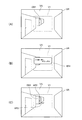
図4は、HMD100の表示状態を示す図であり、(A)は表示領域の位置を示す説明図であり、(B)は第1の表示例を示し、(C)は第2の表示例を示す。図4(A)〜(C)で、VRは使用者の視野を示し、VSは視野VRにおいて使用者が見ることが可能な外景を示す。
V1は、HMD100が画像を表示して使用者に視認させることが可能な領域、すなわち画像表示部20の表示領域を示す。表示領域V1は、図4(A)に示すように、使用者の視野VRのほぼ中央に位置し、視野VRよりも狭い。表示領域V1は視野VRと同じサイズであってもよく、サイズ及び位置は図4(A)の例に限定されない。
4A and 4B are diagrams showing the display state of the HMD 100, FIG. 4A is an explanatory diagram showing the position of the display area, FIG. 4B shows a first display example, and FIG. 4C shows a second display example. Indicates. 4A to 4C, VR indicates a user's visual field, and VS indicates an outside scene that the user can see in the visual field VR.
V1 indicates an area where the HMD 100 can display an image and allow the user to visually recognize it, that is, a display area of the image display unit 20. As shown in FIG. 4A, the display area V1 is located in the approximate center of the user's visual field VR and is narrower than the visual field VR. The display area V1 may be the same size as the visual field VR, and the size and position are not limited to the example of FIG.

表示領域V1は、右導光板261のハーフミラー261A(図2)、及び、左導光板262のハーフミラー262Aが使用者の眼に画像光を反射することによって、形成される。表示領域V1は、右LCD241及び左LCD242に対応する。例えば、右LCD241及び左LCD242の表示可能な領域(表示可能領域)の全体に画像を表示すると、使用者に、表示領域V1の全体のサイズの画像を視認させることができる。   The display region V1 is formed by reflecting image light to the user's eyes by the half mirror 261A (FIG. 2) of the right light guide plate 261 and the half mirror 262A of the left light guide plate 262. The display area V1 corresponds to the right LCD 241 and the left LCD 242. For example, when an image is displayed on the entire displayable area (displayable area) of the right LCD 241 and the left LCD 242, the user can visually recognize an image having the entire size of the display area V1.

HMD100は、表示領域V1に、AR画像を構成する画像やテキスト等の表示オブジェクトを表示する。表示オブジェクトの表示位置、及び表示サイズは、使用者が視認する実空間(外景)の対象物の位置に合わせて決定される。例えば、制御部110が、後述するようにカメラ61の撮像画像を解析し、カメラ61の画角(撮像範囲)と表示領域V1との相対位置を定めるデータに基づいて、表示オブジェクトの表示位置、サイズを決定する処理を行う。上述のように、カメラ61の画角(撮像範囲)は使用者の視野VRに重なり、より好ましくは、カメラ61の画角が視野VRの全体を含む。従って、使用者が視野VRにおいて視認する実空間の物体は、カメラ61の撮像画像に写ることができ、カメラ61の撮像画像から対象物を検出可能である。
対象物は移動可能な物体であってもよいし、異動できない物体すなわち固定的な建造物の一部または全部であってもよいし、物体の表面の一部が対象物であってもよい。
The HMD 100 displays a display object such as an image or text constituting the AR image in the display area V1. The display position and display size of the display object are determined in accordance with the position of the target object in the real space (outside scene) visually recognized by the user. For example, the control unit 110 analyzes the captured image of the camera 61 as will be described later, and displays the display position of the display object based on data that determines the relative position between the angle of view (imaging range) of the camera 61 and the display area V1. Performs processing to determine the size. As described above, the angle of view (imaging range) of the camera 61 overlaps the visual field VR of the user, and more preferably, the angle of view of the camera 61 includes the entire visual field VR. Therefore, an object in real space that the user visually recognizes in the visual field VR can be reflected in the captured image of the camera 61, and the object can be detected from the captured image of the camera 61.
The object may be a movable object, an object that cannot be moved, that is, a part or all of a fixed building, or a part of the surface of the object may be the object.

図4(A)の例では、使用者の視野VRに、実空間に存在するドアである対象物OB1が含まれる。この場合、使用者は画像表示部20を透過して対象物OB1を視認する。HMD100は、カメラ61の撮像画像からAR表示を行う対象である対象物OB1の位置を検出する。ここで検出する位置はカメラ61に対する対象物OB1の相対位置である。また、HMD100は、予め、カメラ61の撮像画像における位置と表示領域V1との相対位置関係を示すデータを、記憶部122に記憶する。このデータは、例えば設定データ122bに含めることができる。この場合、HMD100は、設定データ122bを用いて、撮像画像における対象物OB1の位置から、表示領域V1における対象物OB1の位置を算出する。   In the example of FIG. 4 (A), the visual field VR of the user includes an object OB1 that is a door existing in real space. In this case, the user sees the object OB1 through the image display unit 20. The HMD 100 detects the position of the object OB <b> 1 that is the target for AR display from the captured image of the camera 61. The position detected here is the relative position of the object OB1 with respect to the camera 61. In addition, the HMD 100 stores data indicating the relative positional relationship between the position in the captured image of the camera 61 and the display area V1 in the storage unit 122 in advance. This data can be included in the setting data 122b, for example. In this case, the HMD 100 calculates the position of the object OB1 in the display area V1 from the position of the object OB1 in the captured image using the setting data 122b.

図4(B)には対象物OB1よりも高い視認性で、すなわち目立つように画像AR1を表示する例を示す。図4(B)の例の表示を行う場合、HMD100は、対象物OB1が視認される位置に重なるように画像AR1の表示位置を決定し、画像AR1の表示サイズを、表示領域V1における最大サイズに設定する。図4(B)の画像AR1は、外景VSよりも目立つように表示することが好ましく、例えば、表示領域V1における表示輝度が高輝度に設定され、視認性の高い色で表示される。   FIG. 4B shows an example in which the image AR1 is displayed with higher visibility than the object OB1, that is, in a conspicuous manner. When performing the display of the example of FIG. 4B, the HMD 100 determines the display position of the image AR1 so as to overlap the position where the object OB1 is visually recognized, and sets the display size of the image AR1 to the maximum size in the display region V1. Set to. The image AR1 in FIG. 4B is preferably displayed so as to be more conspicuous than the outside scene VS. For example, the display brightness in the display area V1 is set to high brightness and displayed in a highly visible color.

図4(C)には、外景VSを補完するAR表示の例を示す。図4(C)の画像AR2、AR3は、外景VSの対象物OB1の色やテクスチャーを、外景VSの色とは異なる状態として、使用者に視認させる効果がある画像である。画像AR2は対象物OB1の形状に合わせて、対象物OB1に重なるように表示される。また、画像AR3は画像AR2に接する位置に、画像AR2に合わせたサイズで表示される。図4(C)の例では、画像AR2、AR3が外景VSに馴染むように表示することが好ましい。すなわち、画像AR2、AR3が、対象物OB1及び対象物OB1の周囲の外景VSの視認性を損なわないことが好ましい。このため、例えば、表示領域V1における画像AR2、AR3の表示輝度は、外景VSの視認性を損なわない程度の輝度に設定される。   FIG. 4C shows an example of AR display that complements the outside scene VS. The images AR2 and AR3 in FIG. 4C are images that have an effect of allowing the user to visually recognize the color and texture of the object OB1 of the outside scene VS as different from the color of the outside scene VS. The image AR2 is displayed so as to overlap the object OB1 in accordance with the shape of the object OB1. Further, the image AR3 is displayed at a position in contact with the image AR2 in a size that matches the image AR2. In the example of FIG. 4C, it is preferable that the images AR2 and AR3 are displayed so as to become familiar with the outside scene VS. That is, it is preferable that the images AR2 and AR3 do not impair the visibility of the object OB1 and the outside scene VS around the object OB1. For this reason, for example, the display brightness of the images AR2 and AR3 in the display area V1 is set to a brightness that does not impair the visibility of the outside scene VS.

図4(B)及び(C)に示した表示オブジェクトである画像AR1〜AR3を表示するためのデータは、記憶部122にコンテンツデータ122aとして記憶される。コンテンツデータ122aは、複数の表示オブジェクトのラスター画像データを含んでもよいし、表示オブジェクトを生成するためのベクトル画像データを含んでもよい。或いは、表示オブジェクトを生成するためのパラメーターや関数、テキストデータ等を含んでもよい。表示オブジェクトは、画像に限らず、文字を含んでもよいし、静止画像であっても動画像であってもよい。
また、複数の表示オブジェクトを表示するためのデータをコンテンツデータ122aに含めてもよい。また、コンテンツデータ122aは、音声データを含んでもよく、表示オブジェクトが表示される際に、コンテンツデータ122aの音声データに基づき音声が音声制御部126により出力されてもよい。
Data for displaying the images AR1 to AR3, which are display objects shown in FIGS. 4B and 4C, are stored in the storage unit 122 as content data 122a. The content data 122a may include raster image data of a plurality of display objects, or may include vector image data for generating display objects. Alternatively, it may include parameters, functions, text data, etc. for generating a display object. The display object is not limited to an image, and may include characters, a still image, or a moving image.
Further, data for displaying a plurality of display objects may be included in the content data 122a. The content data 122a may include audio data, and audio may be output from the audio control unit 126 based on the audio data of the content data 122a when a display object is displayed.

HMD100がAR表示において表示する表示オブジェクトの視認性、及び、画像表示部20を透過して使用者に視認される外景VSの視認性は、外部環境から画像表示部20を透過して使用者の眼に入射する光、すなわち外光の影響を受ける。外光の光量が大きい(強度が高い)場合は、光量が小さい(強度が低い)場合に比べて、外景VSの視認性が高まるが、表示オブジェクトの視認性が低下する。また、外光の色によって、表示オブジェクトの視認性が影響を受けることもある。外光の色は、外光に含まれる波長成分のバランスということもできる。可視領域のうち一部の波長域の光強度が高い外光が使用者の眼に入射する場合、外光が白色光である場合に比べて、表示オブジェクトにおいて光強度が高い波長域の視認性が低下する。このため、外光の色によって表示オブジェクトの色の見え方が変化し、表示オブジェクトの一部分の視認性が低下する等の現象が発生する可能性がある。   The visibility of the display object displayed by the HMD 100 in the AR display and the visibility of the outside scene VS that is visible to the user through the image display unit 20 are transmitted through the image display unit 20 from the external environment. It is affected by light incident on the eye, that is, external light. When the amount of external light is large (the intensity is high), the visibility of the outside scene VS is increased, but the visibility of the display object is decreased as compared with the case where the amount of light is small (the intensity is low). In addition, the visibility of the display object may be affected by the color of external light. The color of external light can also be said to be the balance of wavelength components contained in external light. When external light with high light intensity in some wavelengths in the visible region is incident on the user's eyes, the visibility of the wavelength region with high light intensity in the display object is higher than when the external light is white light. Decreases. For this reason, the appearance of the color of the display object changes depending on the color of the external light, and a phenomenon such as a reduction in the visibility of a part of the display object may occur.

HMD100は、外光センサー68で検出する外光の色に応じて、表示領域V1に表示する表示オブジェクトの表示態様を変化させ、表示オブジェクトの視認性を良好に保つ調整機能を備える。外光センサー68はカラーセンサーで構成されるため、例えば、外光の強度を、波長域ごとの強度として検出できる。また、検出結果として、外光センサー68の検出値から、外光の周波数スペクトルを求めてもよい。また、外光センサー68の検出値から、外光の色の色度座標を算出して、検出結果としてもよい。これらの外光の色に関する検出結果を総称して、色調と呼ぶ。HMD100は、外光センサー68の検出値から、上記のいずれかを含む外光の色調を求める。そして、HMD100は、外光の色調の検出結果に基づき、表示オブジェクトの表示色や、表示輝度を調整する。   The HMD 100 includes an adjustment function that changes the display mode of the display object displayed in the display area V1 according to the color of the external light detected by the external light sensor 68, and maintains the visibility of the display object. Since the external light sensor 68 is composed of a color sensor, for example, the intensity of external light can be detected as the intensity for each wavelength region. Further, as a detection result, the frequency spectrum of the external light may be obtained from the detection value of the external light sensor 68. Further, the chromaticity coordinates of the color of the external light may be calculated from the detection value of the external light sensor 68, and the detection result may be obtained. The detection results relating to the color of these external lights are collectively referred to as color tone. The HMD 100 obtains the color tone of the external light including any of the above from the detection value of the external light sensor 68. Then, the HMD 100 adjusts the display color and display luminance of the display object based on the detection result of the color tone of the external light.

HMD100を制御する制御部110(図3)は、AR表示、及び、上記の調整機能を実行する機能部として、撮像制御部111、画像処理部112、及び表示制御部113を備える。
撮像制御部111は、I/F部115、155を介してサブ制御部150にコマンドを送信することにより、カメラ61に撮像を実行させる。サブ制御部150は、撮像制御部111が送信する撮像コマンドを受信して、カメラ61に撮像を実行させ、カメラ61の撮像画像データを撮像制御部111に送信する。
The control unit 110 (FIG. 3) that controls the HMD 100 includes an imaging control unit 111, an image processing unit 112, and a display control unit 113 as functional units that execute the AR display and the adjustment function.
The imaging control unit 111 causes the camera 61 to perform imaging by transmitting a command to the sub-control unit 150 via the I / F units 115 and 155. The sub control unit 150 receives an imaging command transmitted from the imaging control unit 111, causes the camera 61 to execute imaging, and transmits captured image data of the camera 61 to the imaging control unit 111.

表示制御部113は、記憶部122に記憶されたコンテンツデータ122aに基づき、画像表示部20により表示オブジェクトを表示させる。表示制御部113は、コンテンツデータ122a、または、コンテンツデータ122aに基づき生成される表示オブジェクトのデータを、I/F部115、155を介して送信する。また、表示制御部113は、表示オブジェクトの表示位置及びサイズを示すデータ、表示オブジェクトの表示を指示するコマンド等を送信する。サブ制御部150は、制御部110が送信するコマンドやデータを受信し、受信したデータに基づきLCD駆動部167、168及びバックライト駆動部169、170を駆動して表示を実行する。   The display control unit 113 causes the image display unit 20 to display a display object based on the content data 122 a stored in the storage unit 122. The display control unit 113 transmits the content data 122 a or display object data generated based on the content data 122 a via the I / F units 115 and 155. Further, the display control unit 113 transmits data indicating the display position and size of the display object, a command for instructing display of the display object, and the like. The sub-control unit 150 receives commands and data transmitted from the control unit 110 and drives the LCD driving units 167 and 168 and the backlight driving units 169 and 170 based on the received data to execute display.

表示制御部113は、コンテンツデータ122aに基づき表示を行う場合、コンテンツデータ122aから表示オブジェクトの画像データを抽出する処理、または、コンテンツデータ122aに基づき表示オブジェクトの画像データを生成する処理を行う。   When performing display based on the content data 122a, the display control unit 113 performs processing of extracting image data of the display object from the content data 122a or processing of generating image data of the display object based on the content data 122a.

表示制御部113は、表示オブジェクトの表示領域V1における表示位置、すなわちLCD駆動部167、168における表示位置を求める処理を行う。表示制御部113は、AR表示を行わず通常表示を行う場合、コンテンツデータ122aに含まれるデータまたは事前に設定された設定データ122bに基づいて、表示オブジェクトの表示位置を求め、表示位置を指定するコマンドを送信する。   The display control unit 113 performs processing for obtaining the display position of the display object in the display area V1, that is, the display position in the LCD driving units 167 and 168. When the normal display is performed without performing the AR display, the display control unit 113 obtains the display position of the display object based on the data included in the content data 122a or the setting data 122b set in advance, and designates the display position. Send a command.

また、表示制御部113は、AR表示を行う場合、例えばコンテンツデータ122aにAR表示を行うことを示す属性データが含まれる場合、AR表示の対象物OB1を使用者が視認する位置に合わせて、表示オブジェクトの表示位置を決定する処理を行う。この処理で、表示制御部113は、撮像画像から対象物OB1の画像を検出する。HMD100では、検出する対象物OBの画像について、形状、色彩などの特徴量に関するデータを、例えば設定データ122bとして記憶部122に記憶する。表示制御部113は、記憶部122に記憶した設定データ122bを用いて、撮像画像から対象物OB1の画像を検出し、撮像画像における対象物OB1の位置を特定する。さらに、表示制御部113は、LCD駆動部167、168における表示オブジェクトの表示位置を特定し、表示オブジェクトを表示させる。   Further, when performing AR display, for example, when the attribute data indicating that AR display is included in the content data 122a, the display control unit 113 matches the position where the user visually recognizes the object OB1 of AR display, Processing for determining the display position of the display object is performed. In this process, the display control unit 113 detects an image of the object OB1 from the captured image. In the HMD 100, for the image of the object OB to be detected, data relating to the feature amount such as shape and color is stored in the storage unit 122 as setting data 122b, for example. The display control unit 113 detects the image of the object OB1 from the captured image using the setting data 122b stored in the storage unit 122, and specifies the position of the object OB1 in the captured image. Further, the display control unit 113 specifies the display position of the display object on the LCD driving units 167 and 168, and displays the display object.

また、表示制御部113は、外光センサー68の検出値に基づき、画像表示部20に表示する表示オブジェクトの色調、及び/又は輝度を調整する処理を行う。表示制御部113は、外光センサー68の検出値から、外光の波長域ごとの受光強度を取得し、取得した受光強度に基づき、画像表示部20に送信する表示オブジェクトの画像データを、画像処理部112によって処理させる。
画像処理部112は、コンテンツデータ122aから表示制御部113が抽出した画像データまたはコンテンツデータ122aに基づき表示制御部113が生成した画像データに対し、色調を変更する処理、或いは、輝度を調整する処理を実行する。例えば、画像処理部112は、処理対象の画像データを構成する各画素のRGBの階調値を、表示制御部113が指定する補正パラメーターに従って補正する。
Further, the display control unit 113 performs a process of adjusting the color tone and / or luminance of the display object displayed on the image display unit 20 based on the detection value of the external light sensor 68. The display control unit 113 acquires the received light intensity for each wavelength range of the external light from the detection value of the external light sensor 68, and based on the acquired received light intensity, the image data of the display object to be transmitted to the image display unit 20 is displayed as an image. Processing is performed by the processing unit 112.
The image processing unit 112 performs a process of changing the color tone or a process of adjusting the luminance of the image data extracted by the display control unit 113 from the content data 122a or the image data generated by the display control unit 113 based on the content data 122a. Execute. For example, the image processing unit 112 corrects the RGB gradation value of each pixel constituting the image data to be processed according to the correction parameter specified by the display control unit 113.

AR表示を行う場合、表示制御部113は、表示オブジェクトを、対象物OB1の前に重なるように表示する表示態様と、対象物OB1の後ろに重なって視認されるように表示する表示態様とを切り替えてもよい。また、画像処理部112によって画像データを処理させることにより、表示オブジェクトに影が付いたように視認される表示態様で表示してもよい。   When performing the AR display, the display control unit 113 displays a display mode in which the display object is displayed so as to overlap the object OB1 and a display mode in which the display object is displayed so as to be viewed behind the target OB1. You may switch. Further, the image processing unit 112 may process the image data so that the display object is displayed in a display form that is visually recognized as having a shadow.

図5は、HMD100の動作を示すフローチャートであり、(A)は制御装置10の動作を示し、(B)は画像表示部20の動作を示す。
制御装置10に対する操作により、表示動作の開始が指示されると、制御部110が、起動コマンドを生成してサブ制御部150に送信する(ステップS11)。このコマンドは制御データバス41Aを介して伝送され、サブ制御部150はコマンドを受信する(ステップS31)。
FIG. 5 is a flowchart showing the operation of the HMD 100, (A) shows the operation of the control device 10, and (B) shows the operation of the image display unit 20.
When the start of the display operation is instructed by an operation on the control device 10, the control unit 110 generates an activation command and transmits it to the sub-control unit 150 (step S11). This command is transmitted via the control data bus 41A, and the sub-control unit 150 receives the command (step S31).

サブ制御部150は動作を開始し、コマンドに従って、サブ制御部150の初期化を行い、カメラ61、外光センサー68、9軸センサー162、及びGPS163を含む画像表示部20の各部の初期化を行う(ステップS32)。   The sub control unit 150 starts the operation, initializes the sub control unit 150 according to the command, and initializes each part of the image display unit 20 including the camera 61, the external light sensor 68, the 9-axis sensor 162, and the GPS 163. It performs (step S32).

制御部110は、コンテンツデータ122aに基づきAR画像を構成する表示オブジェクトの画像データを取得して、サブ制御部150に送信する(ステップS12)。サブ制御部150は、画像データを受信し、受信した画像データに基づく画像の表示を開始する(ステップS33)。ここで、サブ制御部150は、バックライト駆動部169、170を動作させて右バックライト221及び左バックライト222を点灯させ、受信した画像データに基づきLCD駆動部167、168を動作させて、画像を表示する。   The control unit 110 acquires the image data of the display object constituting the AR image based on the content data 122a, and transmits it to the sub-control unit 150 (step S12). The sub control unit 150 receives the image data and starts displaying an image based on the received image data (step S33). Here, the sub control unit 150 operates the backlight driving units 169 and 170 to turn on the right backlight 221 and the left backlight 222, and operates the LCD driving units 167 and 168 based on the received image data. Display an image.

続いて、制御部110が、外光センサー68による検出実行を指示する検出コマンドを生成して、サブ制御部150に送信する(ステップS13)。
サブ制御部150は、検出コマンドを受信し(ステップS34)、外光センサー68を動作させて検出値を取得して、検出結果すなわち検出値を示すデータを制御部110に送信する(ステップS35)。
Then, the control part 110 produces | generates the detection command which instruct | indicates execution of detection by the external light sensor 68, and transmits to the sub-control part 150 (step S13).
The sub control unit 150 receives the detection command (step S34), operates the external light sensor 68 to acquire the detection value, and transmits the detection result, that is, data indicating the detection value, to the control unit 110 (step S35). .

制御部110は、外光センサー68の検出結果を受信して(ステップS14)、画像処理を実行する(ステップS15)。この画像処理は、外光センサー68の検出結果に基づき表示オブジェクトの視認性を調整する処理であり、詳細は後述する。   The control unit 110 receives the detection result of the external light sensor 68 (step S14), and executes image processing (step S15). This image processing is processing for adjusting the visibility of the display object based on the detection result of the external light sensor 68, and details will be described later.

制御部110は、カメラ61による撮像実行を指示する撮像コマンドを生成してサブ制御部150に送信する(ステップS16)。サブ制御部150は、撮像コマンドを受信して実行し(ステップS36)、カメラ61による撮像を実行させて、撮像画像データを制御部110に送信する(ステップS37)。
制御部110は、撮像画像データを受信し(ステップS18)、撮像画像データに基づいて、AR画像を構成する表示オブジェクトの表示位置、及び表示サイズを決定する(ステップS18)。ステップS18で、制御部110は、上述のようにAR表示の対象である対象物OB1を撮像画像から検出し、撮像画像における対象物OB1の位置及び大きさに基づいて、表示オブジェクトの表示位置およびサイズを決定する。制御部110は、表示オブジェクトの表示位置および表示サイズを指定する表示位置データをサブ制御部150に送信する(ステップS19)。
The control unit 110 generates an imaging command that instructs execution of imaging by the camera 61 and transmits the imaging command to the sub-control unit 150 (step S16). The sub control unit 150 receives and executes the imaging command (step S36), causes the camera 61 to perform imaging, and transmits the captured image data to the control unit 110 (step S37).
The control unit 110 receives the captured image data (step S18), and determines the display position and display size of the display object constituting the AR image based on the captured image data (step S18). In step S18, the control unit 110 detects the target object OB1 that is the target of AR display from the captured image as described above, and displays the display position of the display object and the display object based on the position and size of the target object OB1 in the captured image. Determine the size. The control unit 110 transmits display position data specifying the display position and display size of the display object to the sub-control unit 150 (step S19).

サブ制御部150は、表示位置データを受信し(ステップS38)、右LCD241及び左LCD242における表示オブジェクトの表示位置及びサイズを更新する(ステップS39)。   The sub control unit 150 receives the display position data (step S38), and updates the display position and size of the display object on the right LCD 241 and the left LCD 242 (step S39).

制御部110は、表示を終了するか否かを判定する(ステップS20)。表示を終了しない場合(ステップS20;NO)、制御部110はステップS13に戻る。また、制御部110は、制御装置10の操作により表示の終了が指示された場合、表示を終了すると判定し(ステップS20;YES)、画像データの送信を停止する(ステップS21)。制御部110は表示終了を指示する終了コマンドを生成し、サブ制御部150に送信する(ステップS22)。
サブ制御部150は、終了コマンドを受信したか否かを判定する(ステップS40)。終了コマンドを受信した場合(ステップS40;YES)、サブ制御部150は、LCD駆動部167、168及びバックライト駆動部169、170を停止させて表示を終了する(ステップS41)。また、終了コマンドを受信しない場合(ステップS40;NO)、サブ制御部150はステップS34に戻る。
Control unit 110 determines whether or not to end the display (step S20). When the display is not finished (step S20; NO), the control unit 110 returns to step S13. Further, when the end of the display is instructed by the operation of the control device 10, the control unit 110 determines to end the display (step S20; YES), and stops the transmission of the image data (step S21). The control unit 110 generates an end command for instructing the end of display and transmits it to the sub-control unit 150 (step S22).
The sub-control unit 150 determines whether an end command has been received (step S40). When the end command is received (step S40; YES), the sub control unit 150 stops the LCD driving units 167 and 168 and the backlight driving units 169 and 170 and ends the display (step S41). If the end command is not received (step S40; NO), the sub-control unit 150 returns to step S34.

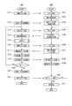
図6は、図5のステップS15で制御部110が実行する画像処理を、詳細に示すフローチャートである。
制御部110は、ステップS14(図5)で受信した外光センサー68の検出結果から、外光の色調を取得する(ステップS101)。外光の色調は、例えば、上述した波長ごとの受光強度、R、G、Bの各波長域の強度、予め設定された特定の波長における受光強度等の検出値や、検出値から求められる周波数スペクトルまたは外光の色度座標等である。本実施形態で説明する「色調」は、外光の色調に関する上記の各種の情報のうち少なくとも1つを含む「色調情報」と呼んでもよい。
FIG. 6 is a flowchart showing in detail the image processing executed by the control unit 110 in step S15 of FIG.
The control unit 110 acquires the color tone of the external light from the detection result of the external light sensor 68 received in step S14 (FIG. 5) (step S101). The color tone of the external light is, for example, a detection value such as the above-described received light intensity for each wavelength, the intensity of each wavelength region of R, G, and B, the received light intensity at a specific wavelength set in advance, or the frequency obtained from the detected value. The spectrum or the chromaticity coordinates of external light. The “color tone” described in the present embodiment may be referred to as “color tone information” including at least one of the above-described various types of information regarding the color tone of external light.

制御部110は、外光の色調に対応する補正パラメーターを生成し、或いは取得する(ステップS102)。ステップS102で、制御部110はステップS101で取得した外光の色調をもとに演算処理を行って、補正パラメーターを生成してもよい。また、外光の色調と補正パラメーターとを対応付けるテーブル(図示略)を、予め、記憶部122に記憶し、このテーブルを用いて補正パラメーターを取得してもよい。この場合のテーブルは、設定データ122bに含めてもよい。
そして、制御部110は、ステップS102で生成または取得した補正パラメーターを用いて、表示オブジェクトの画像データを補正する処理を行う(ステップS103)。
The control unit 110 generates or acquires a correction parameter corresponding to the color tone of external light (step S102). In step S102, the control unit 110 may generate a correction parameter by performing arithmetic processing based on the color tone of the external light acquired in step S101. In addition, a table (not shown) that associates the color tone of external light and the correction parameter may be stored in the storage unit 122 in advance, and the correction parameter may be acquired using this table. The table in this case may be included in the setting data 122b.
Then, the control unit 110 performs a process of correcting the image data of the display object using the correction parameter generated or acquired in Step S102 (Step S103).

図6に示す処理の具体例として、3通りの処理が挙げられる。
第1の処理は、表示オブジェクトの視認性が低下しないように維持する処理である。言い換えれば、外光の影響で表示オブジェクトの視認性が低下する可能性がある場合に、視認性の低下を防止する処理である。
As specific examples of the processing shown in FIG. 6, there are three types of processing.
The first process is a process for maintaining the visibility of the display object so as not to deteriorate. In other words, when the visibility of the display object may be lowered due to the influence of external light, this is a process for preventing the visibility from being lowered.

制御部110は、外光の色調の影響により表示オブジェクトの色調が変化して視認される可能性がある場合、この外光の影響を相殺するように、表示オブジェクトの画像データの階調値を補正する。右LCD241及び左LCD242は、例えばR、G、Bの3色の表示を行う液晶表示パネルで構成され、右バックライト221及び左バックライト222が発する白色光に合わせた色調特性を有する構成となっている。従って、外光が、いわゆる白色光である場合に、表示オブジェクトが本来の色で視認される。外光の色調が白色光とは異なる色調となっている場合、表示オブジェクトを構成する画像光と外光とが重なって使用者の眼に入射することにより、表示オブジェクトが本来の色調とは異なる色調で見える。この場合、制御部110は、外光が白色光である場合と同じように表示オブジェクトが視認されるように、画像データを構成するR、G、Bの各色のデータをそれぞれ補正する。例えば、制御部110は、画像データの各色のガンマ補正を行う。   When there is a possibility that the color tone of the display object is changed due to the influence of the color tone of the external light, the control unit 110 changes the gradation value of the image data of the display object so as to cancel the effect of the external light. to correct. The right LCD 241 and the left LCD 242 are configured by a liquid crystal display panel that displays, for example, three colors R, G, and B, and have a color tone characteristic that matches the white light emitted by the right backlight 221 and the left backlight 222. ing. Therefore, when the external light is so-called white light, the display object is visually recognized in the original color. When the color tone of the external light is different from that of white light, the image light constituting the display object and the external light overlap and enter the user's eyes, so the display object differs from the original color tone It looks in color. In this case, the control unit 110 corrects each of the R, G, and B color data constituting the image data so that the display object is visually recognized as in the case where the external light is white light. For example, the control unit 110 performs gamma correction for each color of the image data.

第2の処理は、表示オブジェクトの視認性をより高くする処理である。
制御部110は、外光の色調とのコントラストが高くなるように、表示オブジェクトの画像データを補正する。第2の処理では、制御部110は、制御部110は、外光の色調とのコントラストが高くなるように、表示オブジェクトの画像データを補正する。この第2の処理の結果、表示オブジェクトが、外光が白色光である場合とは異なる色調で視認されてもよい。
The second process is a process for increasing the visibility of the display object.
The control unit 110 corrects the image data of the display object so that the contrast with the color tone of the external light becomes high. In the second process, the control unit 110 corrects the image data of the display object so that the contrast with the color tone of the external light becomes high. As a result of the second processing, the display object may be visually recognized with a color tone different from that when the external light is white light.

第1及び第2の処理は、例えば、図4(B)に示す画像AR1のように、外景VSに対して目立つように使用者に視認されることが望ましい表示オブジェクトについて、有用である。   The first and second processes are useful for a display object that is desirably visually recognized by the user so as to be conspicuous with respect to the outside scene VS, for example, an image AR1 illustrated in FIG.

第3の処理は、表示オブジェクトの色調を、外光の色調に合わせて変化させる処理である。第3の処理を行う場合、制御部110は表示オブジェクトの色調が外光の色調に近くなるように、画像データの階調値を補正する。
第3の処理によれば、表示オブジェクトが外景VSに溶け込むような視覚効果を得ることができる。この第3の処理は、例えば、図4(C)に示す画像AR2、AR3のように、実空間(対象物)と同時に視認されることで視覚的な効果をもたらす表示オブジェクトについて、有用である。
The third process is a process of changing the color tone of the display object in accordance with the color tone of the external light. When performing the third processing, the control unit 110 corrects the gradation value of the image data so that the color tone of the display object is close to the color tone of the external light.
According to the third process, it is possible to obtain a visual effect such that the display object melts into the outside scene VS. This third process is useful for display objects that bring about a visual effect when viewed simultaneously with the real space (object), such as images AR2 and AR3 shown in FIG. 4C, for example. .

図7は、図5のステップS15で制御部110が実行する画像処理の別の例を、詳細に示すフローチャートである。
図7の画像処理で、制御部110は、外光の明るさ、すなわち外光センサー68が受光する受光強度に対応して画像データを補正する。
FIG. 7 is a flowchart showing in detail another example of the image processing executed by the control unit 110 in step S15 of FIG.
In the image processing of FIG. 7, the control unit 110 corrects the image data in accordance with the brightness of external light, that is, the received light intensity received by the external light sensor 68.

制御部110は、ステップS14(図5)で受信した外光センサー68の検出結果から、外光の強度を算出する(ステップS111)。外光の強度は、例えば、特定の波長における外光センサー68の受光強度であってもよいし、予め設定された複数の波長または波長域における受光強度から算出される値であってもよい。   The control unit 110 calculates the intensity of external light from the detection result of the external light sensor 68 received in step S14 (FIG. 5) (step S111). The intensity of the external light may be, for example, the light reception intensity of the external light sensor 68 at a specific wavelength, or may be a value calculated from the light reception intensity at a plurality of preset wavelengths or wavelength ranges.

制御部110は、外光の強度が、予め設定された設定値より暗いか否かを判定する(ステップS112)。設定値よりも暗い場合(ステップS112;YES)、制御部110は、設定データ122bから暗所用の補正パラメーターを生成または取得し(ステップS113)、この補正パラメーターを用いて表示オブジェクトの画像データを補正する(ステップS114)。また、外光の強度が設定値と同じか、設定値よりも明るい場合(ステップS112;NO)、制御部110は画像データの補正を行わず本処理を終了する。   The controller 110 determines whether or not the intensity of external light is darker than a preset setting value (step S112). If it is darker than the set value (step S112; YES), the control unit 110 generates or acquires a correction parameter for dark place from the setting data 122b (step S113), and corrects the image data of the display object using this correction parameter. (Step S114). If the intensity of the external light is the same as or brighter than the set value (step S112; NO), the control unit 110 ends the process without correcting the image data.

人間の視細胞を構成する杆体細胞と錐体細胞のうち、外光の強度が弱い(外光が暗い)場合には杆体細胞が優位に働くことが知られている。杆体細胞の感光特性(光吸収特性)は500〜550nmにピークを有し、錐体細胞よりも感光特性のピーク波長が短波長側にある。従って、外光が暗い場合は白色よりも青色側の光が強く視認される。図7の画像処理では、杆体細胞によって表示オブジェクトの画像光が強く感じられるように、表示オブジェクトの画像データを、青色が強くなるように補正する。これにより、使用者の眼に入射する光の強度が弱い場合に、表示オブジェクトが良好に視認されるようにすることができる。図7の画像処理では、表示オブジェクトと外景VSとのコントラストが極端に大きくならないように、表示オブジェクトの視認性を向上させることができるという、効果が得られる。   Among rod cells and cone cells constituting human photoreceptor cells, rod cells are known to work predominantly when the intensity of external light is weak (external light is dark). The photosensitive characteristics (light absorption characteristics) of rod cells have a peak at 500 to 550 nm, and the peak wavelength of the photosensitive characteristics is on the shorter wavelength side than cone cells. Therefore, when the outside light is dark, the light on the blue side is more intense than white. In the image processing of FIG. 7, the image data of the display object is corrected so that the blue color becomes strong so that the image light of the display object can be felt strongly by the rod cells. Thereby, when the intensity | strength of the light which injects into a user's eyes is weak, a display object can be made to be visually recognized favorably. The image processing of FIG. 7 has an effect that the visibility of the display object can be improved so that the contrast between the display object and the outside scene VS does not become extremely large.

また、制御部110は、図6に示した画像処理と、図7に示した画像処理とを組み合わせて実行することも可能である。この例を図8に示す。
図8は、図5のステップS15で制御部110が実行する画像処理の別の例を、詳細に示すフローチャートである。なお、図8において、図6及び図7と同様の処理を行う処理ステップについては、同ステップ番号を付す。
The control unit 110 can also execute a combination of the image processing shown in FIG. 6 and the image processing shown in FIG. An example of this is shown in FIG.
FIG. 8 is a flowchart showing in detail another example of the image processing executed by the control unit 110 in step S15 of FIG. In FIG. 8, the same step numbers are assigned to the processing steps that perform the same processing as in FIGS.

図8の画像処理で、制御部110は、画像データの属性、すなわち表示オブジェクトの属性を判定する(ステップS121)。図8に示す画像処理を行う場合、コンテンツデータ122aに含まれる表示オブジェクトの画像データに、表示オブジェクトの属性を示すデータが付加される。表示オブジェクトの属性は、例えば、当該表示オブジェクトを外景VSに対して目立たせるか否か、すなわち表示オブジェクトの視認性を高めるか否かを示す。図4(B)に示した画像AR1と、図4(C)に示した画像AR2、AR3とは、異なる属性を有する。   In the image processing of FIG. 8, the control unit 110 determines the attribute of the image data, that is, the attribute of the display object (step S121). When the image processing shown in FIG. 8 is performed, data indicating the attributes of the display object is added to the image data of the display object included in the content data 122a. The attribute of the display object indicates, for example, whether or not the display object is conspicuous with respect to the outside scene VS, that is, whether or not the visibility of the display object is increased. The image AR1 shown in FIG. 4B and the images AR2 and AR3 shown in FIG. 4C have different attributes.

制御部110は、ステップS121で取得した表示オブジェクトの属性に基づき、表示オブジェクトの視認性を高める処理を行うか否かを判定する(ステップS122)。視認性を高める処理を行う場合(ステップS122;YES)、制御部110は、図7に示したステップS111〜S112の処理を実行し、外光の強度が、予め設定された設定値より暗いか否かを判定する(ステップS112)。   The control unit 110 determines whether or not to perform a process for improving the visibility of the display object based on the attribute of the display object acquired in step S121 (step S122). When performing the process of improving the visibility (step S122; YES), the control unit 110 executes the processes of steps S111 to S112 illustrated in FIG. 7, and whether the intensity of external light is darker than a preset setting value. It is determined whether or not (step S112).

設定値よりも暗い場合(ステップS112;YES)、制御部110は、設定データ122bから暗所用の補正パラメーターを取得する(ステップS113)。
さらに、制御部110は、外光センサー68の検出結果から外光の色調を取得し(ステップS123)、画像データに適用する補正パラメーターを生成する(ステップS124)。ステップS124で、制御部110は、外光の色調に対応して、表示オブジェクトの視認性を高める補正パラメーターに、ステップS113で取得した暗所用の補正パラメーターを合わせた補正パラメーターを生成する。なお、ステップS124で制御部110が生成する補正パラメーターは、図7の画像処理と同様に暗所における視認性を確保でき、かつ、図6を参照して説明した第1または第2の処理と同様の効果が得られるパラメーターであればよく、算出方法等は任意である。
When it is darker than the set value (step S112; YES), the control unit 110 acquires a dark place correction parameter from the setting data 122b (step S113).
Further, the control unit 110 acquires the color tone of the external light from the detection result of the external light sensor 68 (step S123), and generates a correction parameter to be applied to the image data (step S124). In step S124, the control unit 110 generates a correction parameter in which the correction parameter for the dark place acquired in step S113 is combined with the correction parameter for improving the visibility of the display object corresponding to the color tone of the external light. Note that the correction parameter generated by the control unit 110 in step S124 can ensure the visibility in the dark place as in the image processing of FIG. 7, and the first or second processing described with reference to FIG. Any parameter can be used as long as the same effect can be obtained, and the calculation method is arbitrary.

制御部110は、生成した補正パラメーターを用いて表示オブジェクトの画像データを補正する(ステップS125)。さらに、制御部110は、補正後の画像データに対して、コントラストを補正するコントラスト補正処理、及び、エッジ補正処理の少なくともいずれかを実行する(ステップS126)。コントラスト補正処理は、例えば、コントラストを強調して、暗い画像の視認性を高める処理とすることができる。また、エッジ補正処理は、例えば、エッジ強調を行って暗い画像の視認性を高める処理とすることができる。また、コントラスト補正処理でコントラストを低下させ、エッジ補正処理でエッジをぼかす処理を行うことで、表示オブジェクトを外光に馴染ませる効果を得る構成としてもよい。   The control unit 110 corrects the image data of the display object using the generated correction parameter (step S125). Further, the control unit 110 executes at least one of a contrast correction process for correcting the contrast and an edge correction process on the corrected image data (step S126). The contrast correction process can be, for example, a process that enhances the contrast and enhances the visibility of dark images. Further, the edge correction process can be, for example, a process for enhancing the visibility of a dark image by performing edge enhancement. Alternatively, the contrast may be reduced by the contrast correction process, and the edge blur process may be performed by the edge correction process to obtain an effect of making the display object familiar with external light.

また、外光の強度が設定値と同じか、設定値よりも明るい場合(ステップS112;NO)、制御部110は、外光センサー68の検出結果から外光の色調を取得し(ステップS131)、補正パラメーターを生成または取得する(ステップS132)。ステップS132で生成する補正パラメーターは、外光に対して表示オブジェクトの視認性を維持し、或いは高める補正パラメーターであり、図6を参照して説明した第1または第2の処理と同様の効果が得られるパラメーターである。補正パラメーターを生成または取得した後、制御部110は、ステップS125に移行して画像データを補正する。   If the intensity of the external light is equal to or brighter than the set value (step S112; NO), the control unit 110 acquires the color tone of the external light from the detection result of the external light sensor 68 (step S131). Then, a correction parameter is generated or acquired (step S132). The correction parameter generated in step S132 is a correction parameter that maintains or enhances the visibility of the display object with respect to external light, and has the same effect as the first or second processing described with reference to FIG. This is the parameter obtained. After generating or acquiring the correction parameter, the control unit 110 proceeds to step S125 and corrects the image data.

一方、画像データの属性に基づき、表示オブジェクトの視認性を高める処理を行わない場合(ステップS122;NO)、制御部110は、外光センサー68の検出値から外光の色調を取得する(ステップS133)。制御部110は、表示オブジェクトの画像データの色調を、外光の色調に合わせる補正パラメーターを生成または取得し(ステップS134)、この補正パラメーターにより画像データを補正する(ステップS135)。ステップS133〜S135の処理は、図6を参照して説明した第3の処理と同様の処理である。   On the other hand, when the process for increasing the visibility of the display object is not performed based on the attribute of the image data (step S122; NO), the control unit 110 acquires the color tone of the external light from the detection value of the external light sensor 68 (step S122). S133). The control unit 110 generates or acquires a correction parameter that matches the color tone of the image data of the display object with the color tone of the external light (step S134), and corrects the image data using the correction parameter (step S135). The processing in steps S133 to S135 is the same processing as the third processing described with reference to FIG.

図8の画像処理を行う場合、制御部110は、外光の明るさと、表示オブジェクトの属性とに対応して、表示オブジェクトの画像データを補正することにより、表示オブジェクトの視認性を適正な状態とすることができる。   When performing the image processing of FIG. 8, the control unit 110 corrects the visibility of the display object by correcting the image data of the display object according to the brightness of the external light and the attribute of the display object. It can be.

また、外光センサー68が、検出する光の強度のレンジ(検出範囲)を複数段階に切換可能な構成である場合、図7及び8の動作において、外光センサー68のレンジを切り替えてもよい。具体的には、制御部110は、サブ制御部150に送信する検出コマンド(図5(A))により、外光センサー68の検出レンジを指定する。制御部110は、外光センサー68の検出結果が示す受光強度が、現在設定されているレンジの上限より小さく上限に近い値、上限値、或いは上限値を超える値である場合に、外光センサー68のレンジを高強度側に切り替える検出コマンドを送信する。これにより、外光の強度が高い場合であっても、適切に外光を検出できる。また、制御部110は、外光センサー68の検出結果が示す受光強度が、現在設定されているレンジの下限に近い値、下限値、或いは下限値より小さい値である場合に、外光センサー68のレンジを低強度側に切り替える検出コマンドを送信する。これにより、外光の強度が弱い場合であっても、適切に外光を検出できる。そして、制御部110は、外光センサー68のレンジに対応する補正パラメーターを取得または生成し、画像データを補正してもよい。この場合、制御部110は、ステップS112(図7、図8)において、外光センサー68の検出結果から強度を判定する処理に代えて、外光センサー68で設定されているレンジに基づき、外光の強度が設定値より暗いか否かを判定できる。   Further, when the outside light sensor 68 has a configuration in which the range (detection range) of the intensity of light to be detected can be switched in a plurality of stages, the range of the outside light sensor 68 may be switched in the operations of FIGS. . Specifically, the control unit 110 designates the detection range of the outside light sensor 68 by a detection command (FIG. 5A) transmitted to the sub control unit 150. When the received light intensity indicated by the detection result of the external light sensor 68 is a value smaller than the upper limit of the currently set range, close to the upper limit, an upper limit value, or a value exceeding the upper limit value, the external light sensor A detection command for switching the 68 range to the high intensity side is transmitted. Thereby, even if it is a case where the intensity | strength of external light is high, external light can be detected appropriately. In addition, the controller 110 detects that the received light intensity indicated by the detection result of the external light sensor 68 is a value close to the lower limit of the currently set range, a lower limit value, or a value lower than the lower limit value. Send a detection command to switch the range to the low intensity side. Thereby, even if it is a case where the intensity | strength of external light is weak, external light can be detected appropriately. Then, the control unit 110 may acquire or generate a correction parameter corresponding to the range of the external light sensor 68 and correct the image data. In this case, the controller 110 replaces the process of determining the intensity from the detection result of the external light sensor 68 in step S112 (FIGS. 7 and 8) based on the range set by the external light sensor 68. Whether the light intensity is darker than the set value can be determined.

以上説明したように、本発明を適用した第1実施形態のHMD100は、使用者に対し、複数の色光を含む画像光を出力して表示オブジェクトを表示する画像表示部20を備える。HMD100は、光を検出する外光センサー68を備える。制御部110は、外光センサー68の検出結果に基づき、画像表示部20が出力する画像光の色調を制御する。これにより、外光センサー68が検出する光に合わせて、画像光の色調を変えることができる。このため、画像光以外に使用者の視野に入射する光と画像光の色調が調和するように制御したり、画像光の視認性を高めるように色調を制御したりできる。これにより、HMD100が表示する画像の視認性を適切に調整できる。
外光センサー68は、画像表示部20が出力する画像光とは異なる方向からの光を検出するので、画像光以外に使用者の視野に入射する光と画像光の色調が調和するように制御したり、画像光の視認性を高めるように色調を制御したりできる。
As described above, the HMD 100 according to the first embodiment to which the present invention is applied includes the image display unit 20 that outputs image light including a plurality of color lights to the user and displays a display object. The HMD 100 includes an external light sensor 68 that detects light. The control unit 110 controls the color tone of the image light output from the image display unit 20 based on the detection result of the external light sensor 68. Thereby, the color tone of the image light can be changed in accordance with the light detected by the external light sensor 68. For this reason, it is possible to control the color tone of the image light and the light incident on the user's visual field in addition to the image light, or to control the color tone to enhance the visibility of the image light. Thereby, the visibility of the image which HMD100 displays can be adjusted appropriately.
Since the external light sensor 68 detects light from a different direction from the image light output from the image display unit 20, control is performed so that the color tone of the image light and the light incident on the user's field of view other than the image light are harmonized. Or the color tone can be controlled to improve the visibility of the image light.

また、画像表示部20は、使用者の頭部に装着され、使用者の視野に外光が入射可能な状態で画像光を出力する構成を有し、外光センサー68は外光を検出する。このため、使用者の頭部に装着されるHMD100が表示する画像の色調を、使用者の視野に入射する外光に合わせて変化させることにより、画像の視認性を調整できる。
また、外光センサー68は、画像表示部20に隣接して設けられるので、画像表示部20の近傍で外光センサー68が検出する光と画像光の色調が調和するように制御したり、画像光の視認性を高めるように色調を制御したりできる。
The image display unit 20 is mounted on the user's head and has a configuration for outputting image light in a state where the external light can be incident on the user's field of view. The external light sensor 68 detects external light. . For this reason, the visibility of an image can be adjusted by changing the color tone of the image which HMD100 with which a user's head is mounted | worn according to the external light which injects into a user's visual field.
In addition, since the external light sensor 68 is provided adjacent to the image display unit 20, the light detected by the external light sensor 68 in the vicinity of the image display unit 20 and the color tone of the image light are controlled to be in harmony. The color tone can be controlled to enhance the visibility of light.

また、制御部110は、複数の色データを含む画像データに基づき、画像表示部20に画像を構成する色光を出力させ、画像データに含まれる色データの階調値を変更することによって、画像光の色調を変更する。このため、画像データに含まれる色毎の階調値を変化させることで、データ処理によって画像の視認性を調整できる。   Further, the control unit 110 causes the image display unit 20 to output the color light that constitutes the image based on the image data including a plurality of color data, and changes the gradation value of the color data included in the image data, whereby the image is displayed. Change the color of light. For this reason, the visibility of an image can be adjusted by data processing by changing the gradation value for each color included in the image data.

また、外光センサー68は、複数の異なる波長ごとに、受光する光の強度を検出するセンサーを備えるので、使用者の視野に入射する光の色に関する情報を得ることができる。
また、制御部110は、外光センサー68で検出される波長ごとの光の強度に基づいて、画像表示部20が出力する画像光の色調を制御してもよい。この場合、使用者の視野に入射する光の色に対応して画像光の色調を制御することにより、HMD100が表示する画像の視認性を適切に調整できる。
Further, since the external light sensor 68 includes a sensor that detects the intensity of received light for each of a plurality of different wavelengths, information regarding the color of light incident on the user's field of view can be obtained.
Further, the control unit 110 may control the color tone of the image light output from the image display unit 20 based on the light intensity for each wavelength detected by the external light sensor 68. In this case, the visibility of the image displayed by the HMD 100 can be appropriately adjusted by controlling the color tone of the image light corresponding to the color of the light incident on the user's visual field.

また、制御部110は、使用者が画像光を視認する視認性を高めるように、画像光の色調を制御するので、使用者の視野に入射する光の色に対応して、HMD100が表示する画像の視認性を高めることができる。   Moreover, since the control part 110 controls the color tone of image light so that the visibility which a user visually recognizes image light is improved, HMD100 displays according to the color of the light which injects into a user's visual field. The visibility of an image can be improved.

また、制御部110は、画像光の色調を外光センサー68により検出する光の色調に近づけるように、画像光を構成する各々の色光の輝度を制御する。これにより、使用者の視野に入射する光の色に、画像光の色調を適応させて、HMD100が表示する画像を外光等の色に調和させることができる。   In addition, the control unit 110 controls the luminance of each color light constituting the image light so that the color tone of the image light approaches the color tone of the light detected by the external light sensor 68. Thus, the color of the image light can be adapted to the color of light incident on the user's field of view, and the image displayed by the HMD 100 can be harmonized with the color of external light or the like.

また、制御部110は、図6を参照して説明したように、外光センサー68で検出される波長ごとの光の強度に基づいて、使用者が画像光を視認する視認性を高めるように、画像光を構成する各々の色光の輝度を制御する第1及び第2の処理を行える。また、制御部110は、外光センサー68で検出される波長ごとの光の強度に基づいて、画像光の色調を外光センサー68により検出する光の色調に近づけるように、画像光を構成する各々の色光の輝度を制御する第3の処理を行える。そして、図8に示したように、制御部110は、画像表示部20に表示する画像の属性に応じて、第1及び第2処理と、第3処理とを選択して実行できる。このため、外光等に対して画像の視認性を高める処理と、画像を外光等に調和させる処理とを、HMD100が表示する画像の属性に合わせて選択して実行できる。   Further, as described with reference to FIG. 6, the control unit 110 enhances the visibility with which the user visually recognizes the image light based on the light intensity for each wavelength detected by the external light sensor 68. The first and second processes for controlling the luminance of each color light constituting the image light can be performed. In addition, the control unit 110 configures the image light so that the color tone of the image light approaches the color tone of the light detected by the external light sensor 68 based on the light intensity for each wavelength detected by the external light sensor 68. A third process for controlling the luminance of each color light can be performed. Then, as illustrated in FIG. 8, the control unit 110 can select and execute the first and second processes and the third process according to the attribute of the image displayed on the image display unit 20. For this reason, it is possible to select and execute a process for improving the visibility of an image with respect to external light or the like and a process for harmonizing the image with external light or the like according to the attribute of the image displayed by the HMD 100.

ここで、図5のステップS12で、表示オブジェクトの視認性を高める処理を行う高視認性モード、表示オブジェクトを外景に馴染ませ、調和させて表示する処理を行う高調和モード等、表示オブジェクトの視認性に関する処理の種類により、色補正曲線、γ特性、エッジ補正処理が異なる構成としてもよい。また、HMD100を使用するシーンに合わせて色補正曲線、γ特性、エッジ補正処理が異なる構成としてもよい。
例えば、表示オブジェクトと外景の視認性に関して複数の動作モードを設けてもよい。動作モードの例としては、(1)照度が低い暗所の環境(外が暗闇で黒にしか見えない場合など)で、画像光と外景との両方の視認性を高める「低照度環境モード」が挙げられる。また、例えば、(2)真夏の炎天など外光の照度が設定値以上の状態で、作業指示等のマニュアルを含む表示オブジェクトの視認性、可読性を高める「青天下ドキュメント閲覧モードが挙げられる。この動作モードは、視認性優先の「高視認性モード」と呼ぶこともできる。また、例えば、(3)作業標準等の文書を含む表示オブジェクトにおいて文字等の視認性を高め、文書を見ながらの作業を容易にする「ドキュメント優先モード」が挙げられる。この動作モードでは、作業標準の文字を蛍光色等で表示して可読性を高める動作等を含むことができる。また、例えば、(4)AR表示等で表示される表示オブジェクトの視認性を外景に高度に調和させる「付加画像融合モード」あるいは「色フィッティングモード」が挙げられる。HMD100は、動作モードごとに、表示オブジェクトの表示に係る複数のルックアップテーブル(LUT)、演算式(補正曲線:ぼかし、エッチ強調等によるモードの組み合わせ)を有する構成としてもよい。また、上記動作モードに、環境光色対応の画像表示輝度を変更する、複数の動作モードを含んでもよい。
Here, in step S12 of FIG. 5, the visibility of the display object such as a high visibility mode for performing a process for improving the visibility of the display object, a high harmony mode for performing a process for displaying the display object in harmony with the outside scene, and the like. The color correction curve, the γ characteristic, and the edge correction processing may be different depending on the type of processing related to the property. Further, the color correction curve, the γ characteristic, and the edge correction process may be different depending on the scene using the HMD 100.
For example, a plurality of operation modes may be provided for the visibility of the display object and the outside scene. Examples of operation modes include: (1) “Low Illuminance Environment Mode” that enhances the visibility of both image light and the outside scene in a dark environment with low illuminance (such as when the outside is visible only in black in the dark). Is mentioned. Further, for example, (2) a “blue sky document viewing mode” is provided that enhances the visibility and readability of display objects including manuals such as work instructions in the state where the illuminance of outside light is higher than a set value, such as hot summer sun. This operation mode can also be called a “high visibility mode” in which priority is given to visibility. Further, for example, (3) “document priority mode” that improves the visibility of characters and the like in a display object including a document such as a work standard and facilitates work while viewing the document. This operation mode can include an operation for improving the readability by displaying a work standard character in a fluorescent color or the like. Further, for example, (4) “additional image fusion mode” or “color fitting mode” in which the visibility of a display object displayed by AR display or the like is highly harmonized with the outside scene can be cited. The HMD 100 may have a plurality of lookup tables (LUT) related to display of display objects and arithmetic expressions (correction curves: combinations of modes based on blurring, etch enhancement, etc.) for each operation mode. Further, the operation mode may include a plurality of operation modes for changing the image display brightness corresponding to the ambient light color.

また、制御部110は、第1または第2の処理を実行する場合、外光センサー68で検出される光の強度が予め設定された強度より低い場合に、画像光に含まれる各々の色光の輝度の比を予め設定された比に変化させる。具体的には、暗所用の補正パラメーターを利用して、画像データを補正する。このため、外光等の光の強度が低い場合であっても画像の視認性を適切に調整できる。   Further, when executing the first or second processing, the control unit 110, when the intensity of the light detected by the external light sensor 68 is lower than a preset intensity, each color light included in the image light The luminance ratio is changed to a preset ratio. Specifically, the image data is corrected using correction parameters for dark places. For this reason, even when the intensity of light such as outside light is low, the visibility of the image can be adjusted appropriately.

また、制御部110は、外光センサー68で検出される光の強度が予め設定された強度より低い場合に、画像光に含まれる各々の色光の輝度の比を予め設定された比に変化させる。具体的には、暗所用の補正パラメーターを利用して、画像データを補正する。このため、外光等の光の強度が低い場合であっても画像の視認性を適切に調整できる。   In addition, when the intensity of light detected by the external light sensor 68 is lower than a preset intensity, the control unit 110 changes the luminance ratio of each color light included in the image light to a preset ratio. . Specifically, the image data is corrected using correction parameters for dark places. For this reason, even when the intensity of light such as outside light is low, the visibility of the image can be adjusted appropriately.

また、外光センサー68は、検出する受光強度のレンジを切換可能な構成としてもよい。この場合、いずれかのレンジは第1検出状態に相当し、他のレンジは第1検出状態よりも強度の低い光の検出に適する第2検出状態に相当する。制御部110は、外光センサー68のレンジの切り換え又は設定状態に対応して、画像データを補正する補正パラメーターを生成または取得できる。このため、外光センサー68により、高精度で外光を検出できる。   Further, the outside light sensor 68 may be configured to be able to switch the range of received light intensity to be detected. In this case, one of the ranges corresponds to the first detection state, and the other range corresponds to the second detection state suitable for detecting light having a lower intensity than the first detection state. The control unit 110 can generate or acquire a correction parameter for correcting the image data in response to the range switching or setting state of the external light sensor 68. Therefore, the external light sensor 68 can detect external light with high accuracy.

また、制御部110は、図8を参照して説明したように、外光センサー68で検出される光の強度が予め設定された強度より低い場合に、画像表示部20により表示する画像の画像データに対しコントラスト補正処理及び/又はエッジ補正処理を実行する。このため、外光等の光の強度が低い場合に、画像の視認性をより効果的に高めることができる。   In addition, as described with reference to FIG. 8, the control unit 110 displays an image of an image displayed by the image display unit 20 when the intensity of light detected by the external light sensor 68 is lower than a preset intensity. Contrast correction processing and / or edge correction processing is performed on the data. For this reason, when the intensity | strength of light, such as external light, is low, the visibility of an image can be improved more effectively.

[第2実施形態]
図9は、本発明を適用した第2実施形態におけるHMD100の動作の説明図であり、(A)は表示領域に対応して撮像画像に設けられる領域を示し、(B)は表示領域を示す。この第2実施形態におけるHMD100は、外光センサー68の構成を除いて第1実施形態と共通であるため、HMD100の構成については同符号を用いて説明を省略する。
[Second Embodiment]
FIG. 9 is an explanatory diagram of the operation of the HMD 100 in the second embodiment to which the present invention is applied. (A) shows an area provided in the captured image corresponding to the display area, and (B) shows the display area. . Since the HMD 100 in the second embodiment is common to the first embodiment except for the configuration of the external light sensor 68, the configuration of the HMD 100 is denoted by the same reference numerals and the description thereof is omitted.

第2実施形態における外光センサー68は、外光を検出する検出範囲が設定され、検出範囲における外光の色調を、検出範囲における位置と対応付けて検出可能な構成である。この構成は、例えば、外光センサー68として、カラー撮像が可能なデジタルカメラを採用することで、実現できる。   The outside light sensor 68 in the second embodiment has a configuration in which a detection range for detecting outside light is set, and the color tone of outside light in the detection range can be detected in association with the position in the detection range. This configuration can be realized, for example, by adopting a digital camera capable of color imaging as the external light sensor 68.

図9(A)に示す例では、使用者の視野VRに対応して外光検出範囲V2が設定される。外光検出範囲V2は、外光センサー68が外光を検出する範囲であり、4つの領域V21、V22、V23、V24に分割される。外光センサー68は、4つの領域V21〜V24のそれぞれについて、外光の受光強度を検出し、検出値を出力する。   In the example shown in FIG. 9A, the external light detection range V2 is set corresponding to the visual field VR of the user. The outside light detection range V2 is a range in which the outside light sensor 68 detects outside light, and is divided into four regions V21, V22, V23, and V24. The external light sensor 68 detects the received light intensity of the external light for each of the four regions V21 to V24 and outputs a detection value.

外光検出範囲V2は、表示領域V1に対応付けられる。第2実施形態では、制御部110は、図9(B)に示すように、表示領域V1を4つの小領域V11、V12、V13、V14に分割し、小領域V11〜V14のそれぞれについて、表示オブジェクトの色調を補正できる。
外光センサー68が、右光学像表示部26及び左光学像表示部28とは離れた位置に配置され、表示領域V1に実際に入射する外光を直接検出しない構成とすることもできる。この場合、外光センサー68の外光検出範囲V2は、実際に外光センサー68が外光を受光する位置から離れた位置となる。制御部110は、外光センサー68の実際の検出値を、外光検出範囲V2における外光の色調に変換することで、外光検出範囲V2の外光の色調を間接的に検出できる。また、表示領域V1と外光検出範囲V2とを対応付けるパラメーターや演算式を記憶部122に記憶しておき、このパラメーターや演算式を制御部110が利用する構成とすることも可能である。
The outside light detection range V2 is associated with the display area V1. In the second embodiment, the control unit 110 divides the display area V1 into four small areas V11, V12, V13, and V14 as shown in FIG. 9B, and displays each of the small areas V11 to V14. You can correct the color of the object.
The external light sensor 68 may be disposed at a position distant from the right optical image display unit 26 and the left optical image display unit 28 and may not directly detect external light that actually enters the display region V1. In this case, the outside light detection range V2 of the outside light sensor 68 is a position away from the position where the outside light sensor 68 actually receives outside light. The control unit 110 can indirectly detect the color tone of the external light in the external light detection range V2 by converting the actual detection value of the external light sensor 68 into the color tone of the external light in the external light detection range V2. It is also possible to store parameters and arithmetic expressions for associating the display area V1 with the outside light detection range V2 in the storage unit 122 and use the parameters and arithmetic expressions by the control unit 110.

図10は、第2実施形態におけるHMD100の動作を示すフローチャートである。図10の動作は、図5(A)のステップS12において実行され、上述した図6、図7、図8の動作の別の例に相当する。   FIG. 10 is a flowchart showing the operation of the HMD 100 in the second embodiment. The operation in FIG. 10 is executed in step S12 in FIG. 5A, and corresponds to another example of the operations in FIGS. 6, 7, and 8 described above.

制御部110は、外光センサー68の検出値をもとに、外光検出範囲V2における領域V21〜V24のそれぞれの色調を取得する(ステップS201)。各領域V21〜V24について取得する色調は、上記第1実施形態のステップS101等で取得する色調と同様である。制御部110は、ステップS201で取得した色調に基づいて、表示領域V1の小領域V11〜V14のそれぞれについて補正パラメーターを生成または取得する(ステップS202)。   The control unit 110 acquires each color tone of the regions V21 to V24 in the external light detection range V2 based on the detection value of the external light sensor 68 (step S201). The color tone acquired for each of the regions V21 to V24 is the same as the color tone acquired in step S101 of the first embodiment. The controller 110 generates or acquires correction parameters for each of the small areas V11 to V14 of the display area V1 based on the color tone acquired in step S201 (step S202).

制御部110は、表示オブジェクトの画像データを取得し、この画像データを、小領域V11〜V14に対応して分割する(ステップS203)。そして、分割した画像データのそれぞれに対し、ステップS202の補正パラメーターを用いて補正を実行する(ステップS204)。   The control unit 110 acquires image data of the display object and divides this image data corresponding to the small areas V11 to V14 (step S203). Then, correction is performed on each of the divided image data using the correction parameter in step S202 (step S204).

このように、制御部110は、外光センサー68により使用者の視野に入射する外光を検出した検出結果に基づき、表示領域V1を複数の小領域V11〜V14に区分して、小領域V11〜V14ごとに画像光の色調を制御する。この第2実施形態によれば、視野VRに入射する外光の色調が、視野VRの場所によって異なる場合に、表示オブジェクトを構成する画像光の色調を、外光に対応して細かく補正できる。このため、視野VRにおける外光の色調の差がある場合に、表示オブジェクトの視認性を効果的に調整できる。   As described above, the control unit 110 divides the display area V1 into the plurality of small areas V11 to V14 based on the detection result of detecting the external light incident on the user's visual field by the external light sensor 68, and the small area V11. The color tone of the image light is controlled for each V14. According to the second embodiment, when the color tone of the external light incident on the visual field VR varies depending on the location of the visual field VR, the color tone of the image light constituting the display object can be finely corrected corresponding to the external light. For this reason, when there is a difference in color tone of external light in the visual field VR, the visibility of the display object can be effectively adjusted.

[第3実施形態]
続いて、本発明を適用した第3実施形態について説明する。第3実施形態におけるHMD100は、第1実施形態と共通であるため、HMD100の構成については同符号を用いて説明を省略する。
[Third Embodiment]
Next, a third embodiment to which the present invention is applied will be described. Since the HMD 100 in the third embodiment is common to the first embodiment, the configuration of the HMD 100 is denoted by the same reference numerals and description thereof is omitted.

第3実施形態で、制御部110は、調光板20Aの色調に対応して、表示オブジェクトの画像データを補正する。上述のように、調光板20Aは右光学像表示部26及び左光学像表示部28の外側に位置するので、視野VRに入射する外光は調光板20Aを透過する。このため、外光の色調は調光板20Aの光透過特性(可視光領域における透過スペクトル)の影響を受ける。また、調光板20Aは、上述のように着脱可能な構成とすることが可能であり、調光板20Aを非装着状態で使用すること、及び、光透過特性が異なる複数の調光板20Aを交換して装着することが考え得る。この第3実施形態では、画像表示部20に装着される調光板20Aの種類に対応して、表示オブジェクトの色調を調整する例を説明する。   In the third embodiment, the control unit 110 corrects the image data of the display object in accordance with the color tone of the light control plate 20A. As described above, since the light control plate 20A is positioned outside the right optical image display unit 26 and the left optical image display unit 28, external light incident on the visual field VR is transmitted through the light control plate 20A. For this reason, the color tone of external light is affected by the light transmission characteristics (transmission spectrum in the visible light region) of the light control plate 20A. In addition, the light control plate 20A can be configured to be removable as described above, and the light control plate 20A is used in a non-mounted state, and a plurality of light control plates 20A having different light transmission characteristics. It is possible to replace and install the In the third embodiment, an example will be described in which the color tone of the display object is adjusted in accordance with the type of the light control plate 20A attached to the image display unit 20.

図11は、第3実施形態におけるHMD100の動作を示すフローチャートである。図11の動作は、図5(A)のステップS12において実行され、上述した図6、図7、図8の動作の別の例に相当する。   FIG. 11 is a flowchart showing the operation of the HMD 100 in the third embodiment. The operation of FIG. 11 is executed in step S12 of FIG. 5A, and corresponds to another example of the operations of FIG. 6, FIG. 7, and FIG.

制御部110は、ステップS14(図5)で受信した外光センサー68の検出結果から、外光の色調を取得する(ステップS211)。外光の色調は、上述した図6のステップS101で取得する色調と同様である。制御部110は、外光の色調に対応する補正パラメーターを生成し、或いは取得する(ステップS212)。   The control unit 110 acquires the color tone of the external light from the detection result of the external light sensor 68 received in step S14 (FIG. 5) (step S211). The color tone of the external light is the same as the color tone acquired in step S101 in FIG. The control unit 110 generates or acquires a correction parameter corresponding to the color tone of outside light (step S212).

制御部110は、画像表示部20に装着されている調光板20Aの種類を取得し、或いは判定する(ステップS213)。ステップS213では、調光板20Aが装着されていない場合、非装着と判定される。
例えば、調光板20Aの装着状態、すなわち装着されている調光板20Aの種類を示すデータが記憶部122に記憶されている場合、制御部110は、記憶部122に記憶されたデータに基づき、調光板20Aの種類を取得する。このデータは、例えば使用者が制御装置10を操作して入力する。また、画像表示部20において調光板20Aの種類を検出する検出機構を設けてもよい。例えば、調光板20Aには調光板20Aの種類に対応する構造体(例えば、突起や切り欠き)を設け、フレーム2には調光板20Aの構造体に機械的に接触する検出部(図示略)を設けた構成を採用できる。この場合、検出部において調光板20Aの構造体の接触/非接触を検出すれば、この検出結果に基づいて制御部110が調光板20Aの種類を判定できる。
The control unit 110 acquires or determines the type of the light control plate 20A attached to the image display unit 20 (step S213). In step S213, when the light control plate 20A is not attached, it is determined that it is not attached.
For example, when data indicating the mounting state of the light control plate 20A, that is, the type of the light control plate 20A that is mounted is stored in the storage unit 122, the control unit 110 is based on the data stored in the storage unit 122. The type of the light control plate 20A is acquired. This data is input by operating the control device 10 by the user, for example. Further, a detection mechanism for detecting the type of the light control plate 20A in the image display unit 20 may be provided. For example, the dimming plate 20A is provided with a structure (for example, a protrusion or a notch) corresponding to the type of the dimming plate 20A, and the frame 2 has a detecting unit that mechanically contacts the structure of the dimming plate 20A ( A configuration provided with a not shown) can be employed. In this case, if the detection unit detects contact / non-contact of the structure of the light control plate 20A, the control unit 110 can determine the type of the light control plate 20A based on the detection result.

制御部110は、調光板20Aの種類に対応する補正パラメーターを取得する(ステップS214)。第3実施形態では、記憶部122に、調光板20Aの種類に対応する補正パラメーターが予め記憶される。制御部110は、ステップS214で取得した補正パラメーターと、ステップS212で生成または取得した補正パラメーターとをもとに、画像データに適用する補正パラメーターを生成する(ステップS215)。ステップS215で制御部110が生成する補正パラメーターは、外光センサー68が検出した外光の色調に対し、調光板20Aを透過することで外光の色調が変化することを加味した補正パラメーターである。これにより、制御部110は、調光板20Aを透過した外光の色調に対応する補正を行うことが可能となる。
制御部110は、ステップS215で生成した補正パラメーターを用いて、表示オブジェクトの画像データを補正する処理を行う(ステップS216)。
The control unit 110 acquires a correction parameter corresponding to the type of the light control plate 20A (step S214). In the third embodiment, correction parameters corresponding to the type of light control plate 20A are stored in the storage unit 122 in advance. The control unit 110 generates a correction parameter to be applied to the image data based on the correction parameter acquired in step S214 and the correction parameter generated or acquired in step S212 (step S215). The correction parameter generated by the control unit 110 in step S215 is a correction parameter that takes into account the change in the color tone of the external light transmitted through the light control plate 20A with respect to the color tone of the external light detected by the external light sensor 68. is there. Thereby, the control part 110 can perform correction | amendment corresponding to the color tone of the external light which permeate | transmitted the light control board 20A.
The control unit 110 performs a process of correcting the image data of the display object using the correction parameter generated in step S215 (step S216).

第3実施形態によれば、調光板20Aを透過しない外光を外光センサー68で検出する構成において、調光板20Aを透過することによって外光の色調が変化する場合に、この色調の変化を加味して表示オブジェクトの色調を補正できる。このため、実際に使用者の眼に入射する外光の影響に対応して、表示オブジェクトの視認性を調整できる。
なお、第3実施形態と同様の効果を得る方法として、外光センサー68が、調光板20Aを透過する外光を受光する構成とすることができる。この場合、外光センサー68の受光面または受光部を、調光板20Aにより覆われる位置に配置すればよい。
According to the third embodiment, in the configuration in which the external light that does not pass through the light control plate 20A is detected by the external light sensor 68, when the color tone of the external light changes by transmitting through the light control plate 20A, The color tone of the display object can be corrected in consideration of changes. For this reason, the visibility of a display object can be adjusted corresponding to the influence of the external light which actually injects into a user's eyes.
As a method of obtaining the same effect as that of the third embodiment, the external light sensor 68 can receive external light that passes through the light control plate 20A. In this case, the light receiving surface or light receiving portion of the external light sensor 68 may be arranged at a position covered by the light control plate 20A.

[第4実施形態]
図12は、本発明を適用した第4実施形態の構成を示すブロック図である。
第4実施形態では、HMD100において、画像表示部20に設けられるサブ制御部150が、外光センサー68の検出結果に基づいて、画像データを補正する処理部114を備える。すなわち、サブ制御部150を構成するCPU(図示略)が、サブ制御部150のROM(図示略)または記憶部122に記憶されるプログラムを実行することにより、処理部114の機能を実行する。
[Fourth Embodiment]
FIG. 12 is a block diagram showing a configuration of the fourth embodiment to which the present invention is applied.
In the fourth embodiment, in the HMD 100, the sub-control unit 150 provided in the image display unit 20 includes a processing unit 114 that corrects image data based on the detection result of the external light sensor 68. That is, the CPU (not shown) constituting the sub control unit 150 executes the function of the processing unit 114 by executing a program stored in the ROM (not shown) of the sub control unit 150 or the storage unit 122.

この場合、制御部110は、図5(A)のステップS13〜S15に示した動作を実行せず、サブ制御部150は、制御部110からコマンドを受信することなく、処理部114により外光センサー68による検出を実行させる。さらに、サブ制御部150は、処理部114により、図5(A)のステップS15で示す画像処理を実行する。この画像処理としては、図6、図7、図8、図10、及び図11で説明したいずれの処理も実行可能である。   In this case, the control unit 110 does not execute the operations shown in steps S13 to S15 in FIG. 5A, and the sub-control unit 150 receives external light from the processing unit 114 without receiving a command from the control unit 110. Detection by the sensor 68 is executed. Further, the sub control unit 150 causes the processing unit 114 to execute the image processing shown in step S15 of FIG. As this image processing, any of the processes described with reference to FIGS. 6, 7, 8, 10, and 11 can be executed.

この構成によれば、上述した第1〜第3実施形態と同様の効果を得ることができる。また、サブ制御部150は、制御部110の撮像制御部111及び表示制御部113の機能をプログラムにより実行する構成とすることができる。
さらに、制御部110の全ての機能または一部の機能を、サブ制御部150が実行する構成とすることが可能である。また、制御部110だけでなく、メモリー121、記憶部122、電源制御部123、UI制御部124、無線I/F制御部125、音声制御部126、センサーIC127、及び外部I/F部128を、画像表示部20に実装する構成としてもよい。また、制御装置10にUI制御部124、センサーIC127、及び外部I/F部128のみを設け、その他の機能部を画像表示部20に設けてもよい。また、制御装置10と画像表示部20とを無線通信回線により接続してもよい。
According to this configuration, the same effects as those of the first to third embodiments described above can be obtained. In addition, the sub control unit 150 can be configured to execute the functions of the imaging control unit 111 and the display control unit 113 of the control unit 110 by a program.
Further, all or some of the functions of the control unit 110 can be configured to be executed by the sub-control unit 150. In addition to the control unit 110, the memory 121, the storage unit 122, the power supply control unit 123, the UI control unit 124, the wireless I / F control unit 125, the audio control unit 126, the sensor IC 127, and the external I / F unit 128 are included. Alternatively, the image display unit 20 may be mounted. Further, only the UI control unit 124, the sensor IC 127, and the external I / F unit 128 may be provided in the control device 10, and other functional units may be provided in the image display unit 20. Further, the control device 10 and the image display unit 20 may be connected by a wireless communication line.

なお、この発明は上記各実施形態の構成に限られるものではなく、その要旨を逸脱しない範囲において種々の態様において実施することが可能である。
例えば、上記各実施形態では本体の一例として、眼鏡型のフレーム2を例示したが、本体の形状は眼鏡型に限定されない。使用者の頭部に装着または固定され、使用者の左眼及び右眼に対応して画像を表示する表示部を備えていればよい。例えば、上述した眼鏡型の他に、使用者の顔の上部を覆うスノーゴーグル様の形状であってもよいし、双眼鏡のように使用者の左右の眼のそれぞれの前方に配置される形状であってもよい。
また、例えば、画像表示部20に代えて、例えば帽子のように装着する画像表示部等の他の方式の画像表示部を採用してもよい。また、本発明の表示装置は、例えば、自動車や飛行機等の車両に搭載されるヘッドマウントディスプレイとして構成されてもよい。また、例えば、ヘルメット等の身体防護具に内蔵されたヘッドマウントディスプレイとして構成されてもよい。
In addition, this invention is not restricted to the structure of said each embodiment, In the range which does not deviate from the summary, it can be implemented in a various aspect.
For example, in the above embodiments, the spectacle-type frame 2 is illustrated as an example of the main body, but the shape of the main body is not limited to the spectacle-type. What is necessary is just to provide the display part which mounts or fixes to a user's head and displays an image corresponding to a user's left eye and right eye. For example, in addition to the above-described glasses type, a snow goggle-like shape that covers the upper part of the user's face may be used, or a shape that is arranged in front of each of the left and right eyes of the user like binoculars. There may be.
Further, for example, instead of the image display unit 20, another type of image display unit such as an image display unit worn like a hat may be employed. The display device of the present invention may be configured as a head mounted display mounted on a vehicle such as an automobile or an airplane. Further, for example, it may be configured as a head-mounted display built in a body protective device such as a helmet.

また、制御装置10として、ノート型コンピューター、タブレット型コンピューター又はデスクトップ型コンピューターを用いてもよい。或いは、制御装置10として、ゲーム機や携帯型電話機やスマートフォンや携帯型メディアプレーヤーを含む携帯型電子機器、その他の専用機器等を用いてもよい。
また、例えば、画像表示部20において画像光を生成する構成として、有機EL(有機エレクトロルミネッセンス、Organic Electro-Luminescence)のディスプレイと、有機EL制御部とを備える構成としてもよい。また、画像光を生成する構成として、LCOS(Liquid crystal on silicon, LCoSは登録商標)や、デジタル・マイクロミラー・デバイス等を用いることもできる。
As the control device 10, a notebook computer, a tablet computer, or a desktop computer may be used. Alternatively, a game machine, a portable phone, a portable electronic device including a smartphone or a portable media player, other dedicated devices, or the like may be used as the control device 10.
For example, as a configuration for generating image light in the image display unit 20, a configuration including an organic EL (Organic Electro-Luminescence) display and an organic EL control unit may be used. Further, as a configuration for generating image light, LCOS (Liquid crystal on silicon, LCoS is a registered trademark), a digital micromirror device, or the like can be used.

また、画像光を使用者の眼に導く光学系としては、外部から装置に向けて入射する外光を透過する光学部材を備え、画像光とともに使用者の眼に入射させる構成を採用できる。また、使用者の眼の前方に位置して使用者の視界の一部または全部に重なる光学部材を用いてもよい。さらに、レーザー光等を走査させて画像光とする走査方式の光学系を採用してもよい。また、光学部材の内部で画像光を導光させるものに限らず、使用者の眼に向けて画像光を屈折及び/または反射させて導く機能のみを有するものであってもよい。
例えば、レーザー網膜投影型のヘッドマウントディスプレイに対して本発明を適用することも可能である。すなわち、光射出部が、レーザー光源と、レーザー光源を使用者の眼に導く光学系とを備え、レーザー光を使用者の眼に入射させて網膜上を走査し、網膜に結像させることにより、使用者に画像を視認させる構成を採用してもよい。
また、本発明を、MEMSミラーを用いた走査光学系を採用し、MEMSディスプレイ技術を利用した表示装置に適用することも可能である。すなわち、信号光形成部と、信号光形成部が射出する光を走査するMEMSミラーを有する走査光学系と、走査光学系により走査される光によって虚像が形成される光学部材とを光射出部として備えてもよい。この構成では、信号光形成部が射出した光がMEMSミラーにより反射され、光学部材に入射し、光学部材の中を導かれて、虚像形成面に達する。MEMSミラーが光を走査することにより、虚像形成面に虚像が形成され、この虚像を使用者が眼で捉えることで、画像が認識される。この場合の光学部品は、例えば上記実施形態の右導光板261及び左導光板262のように、複数回の反射を経て光を導くものであってもよく、ハーフミラー面を利用してもよい。
The optical system that guides the image light to the user's eyes may include an optical member that transmits external light that is incident on the apparatus from the outside and that is incident on the user's eyes together with the image light. Moreover, you may use the optical member which is located ahead of a user's eyes and overlaps a part or all of a user's visual field. Further, a scanning optical system that scans a laser beam or the like to obtain image light may be employed. Further, the optical member is not limited to guiding the image light inside the optical member, and may have only a function of guiding the image light by refracting and / or reflecting it toward the user's eyes.
For example, the present invention can also be applied to a laser retinal projection type head mounted display. That is, the light emitting unit includes a laser light source and an optical system that guides the laser light source to the user's eyes, and the laser light is incident on the user's eyes to scan the retina and form an image on the retina. A configuration that allows the user to visually recognize an image may be employed.
Further, the present invention can be applied to a display device that employs a scanning optical system using a MEMS mirror and uses MEMS display technology. That is, a light emitting unit includes a signal light forming unit, a scanning optical system having a MEMS mirror that scans light emitted from the signal light forming unit, and an optical member on which a virtual image is formed by light scanned by the scanning optical system. You may prepare. In this configuration, the light emitted from the signal light forming unit is reflected by the MEMS mirror, enters the optical member, is guided through the optical member, and reaches the virtual image forming surface. When the MEMS mirror scans the light, a virtual image is formed on the virtual image forming surface, and the user recognizes the virtual image with the eyes, thereby recognizing the image. The optical component in this case may be one that guides light through a plurality of reflections, such as the right light guide plate 261 and the left light guide plate 262 of the above embodiment, and may use a half mirror surface. .

また、図3に示した各機能ブロックのうち少なくとも一部は、ハードウェアで実現してもよいし、ハードウェアとソフトウェアの協働により実現される構成としてもよく、図3に示した通りに独立したハードウェア資源を配置する構成に限定されない。また、図3に示した各機能部は、マイクロプロセッサーとICで構成する例に制限されず、より大規模の集積回路に複数の機能部を実装する構成としてもよいし、SoC(System-on-a-chip)等の形態としても良い。また、制御装置10に形成された構成が重複して画像表示部20に形成されていてもよい。   Further, at least a part of each functional block shown in FIG. 3 may be realized by hardware, or may be realized by cooperation of hardware and software, as shown in FIG. It is not limited to a configuration in which independent hardware resources are arranged. Further, each functional unit shown in FIG. 3 is not limited to an example constituted by a microprocessor and an IC, and a configuration in which a plurality of functional units are mounted on a larger scale integrated circuit may be adopted. -a-chip) or the like. Further, the configuration formed in the control device 10 may be formed in the image display unit 20 in an overlapping manner.

10…制御装置、20…画像表示部(表示部)、20A…調光板、22…右表示駆動部、24…左表示駆動部、40…接続部、61…カメラ、63…マイク、68…外光センサー(光検出部)、100…頭部装着型表示装置(表示装置)、110…制御部、111…撮像制御部、112…画像処理部、113…表示制御部、114…処理部、121…メモリー、122…フラッシュメモリー、122a…コンテンツデータ、122b…設定データ、125…無線I/F制御部、127…センサーIC、128…外部I/F部、150…サブ制御部、155…I/F部、162…9軸センサー、163…GPS、165…EEPROM、167、168…LCD駆動部、169、170…バックライト駆動部、221…右バックライト、222…左バックライト、241…右液晶ディスプレイ、242…左液晶ディスプレイ、251…右投写光学系、252…左投写光学系。   DESCRIPTION OF SYMBOLS 10 ... Control apparatus, 20 ... Image display part (display part), 20A ... Light control board, 22 ... Right display drive part, 24 ... Left display drive part, 40 ... Connection part, 61 ... Camera, 63 ... Microphone, 68 ... External light sensor (light detection unit), 100 ... head-mounted display device (display device), 110 ... control unit, 111 ... imaging control unit, 112 ... image processing unit, 113 ... display control unit, 114 ... processing unit, 121 ... Memory, 122 ... Flash memory, 122a ... Content data, 122b ... Setting data, 125 ... Wireless I / F control unit, 127 ... Sensor IC, 128 ... External I / F unit, 150 ... Sub control unit, 155 ... I / F section, 162 ... 9-axis sensor, 163 ... GPS, 165 ... EEPROM, 167, 168 ... LCD drive section, 169, 170 ... backlight drive section, 221 ... right backlight, 222 Left backlight, 241 ... right liquid crystal display, 242 ... left a liquid crystal display, 251 ... right projection optical system, 252 ... left projection optical system.

Claims (12)

使用者に対し、複数の色光を含む画像光を出力して画像を表示する表示部と、
光を検出する光検出部と、
前記光検出部の検出結果に基づき、前記表示部が出力する前記画像光の色調を制御する制御部と、を備え、
前記光検出部は、複数の異なる波長ごとに、受光する光の強度を検出するセンサーを備え、
前記制御部は、前記光検出部で検出される波長ごとの光の強度に基づいて、前記使用者が前記画像光を視認する視認性を高めるように、前記画像光を構成する各々の前記色光の輝度を制御する第1処理と、
前記光検出部で検出される波長ごとの光の強度に基づいて、前記画像光の色調を前記光検出部により検出する光の色調に近づけるように、前記画像光を構成する各々の前記色光の輝度を制御する第2処理と、を実行可能に構成され、
前記表示部に表示する画像の属性に応じて前記第1処理及び前記第2処理のいずれかを選択して実行すること、
を特徴とする表示装置。
A display unit that displays image by outputting image light including a plurality of color lights to a user;
A light detection unit for detecting light;
A control unit that controls the color tone of the image light output from the display unit based on the detection result of the light detection unit;
The light detection unit includes a sensor that detects the intensity of received light for each of a plurality of different wavelengths.
Each of the color lights constituting the image light is configured so that the control unit enhances the visibility for the user to visually recognize the image light based on the intensity of light for each wavelength detected by the light detection unit. A first process for controlling the brightness of
Based on the light intensity for each wavelength detected by the light detection unit, the color light of each of the color lights constituting the image light is made closer to the color tone of the light detected by the light detection unit. A second process for controlling the brightness, and configured to be executable.
Selecting and executing either the first process or the second process according to an attribute of an image displayed on the display unit;
A display device.
前記光検出部は、前記表示部が出力する前記画像光とは異なる方向からの光を検出すること、
を特徴とする請求項1記載の表示装置。
The light detection unit detects light from a direction different from the image light output from the display unit;
The display device according to claim 1.
前記表示部は、前記使用者の頭部に装着され、前記使用者の視野に外光が入射可能な状態で前記画像光を出力する構成を有し、
前記光検出部は前記使用者の視野に入射する前記外光を検出すること、
を特徴とする請求項2記載の表示装置。
The display unit is mounted on the user's head, and has a configuration for outputting the image light in a state in which external light can be incident on the user's visual field.
The light detector detects the external light incident on the user's field of view;
The display device according to claim 2.
使用者に対し、複数の色光を含む画像光を出力して画像を表示する表示部と、
前記表示部に隣接して設けられ、前記使用者の顔の前方からの光を検出する光検出部と、
前記光検出部の検出結果に基づき、前記表示部が出力する前記画像光の色調を制御する制御部と、を備え、
前記光検出部は、複数の異なる波長ごとに、受光する光の強度を検出するセンサーを備え、
前記制御部は、前記光検出部で検出される波長ごとの光の強度に基づいて、前記使用者が前記画像光を視認する視認性を高めるように、前記画像光を構成する各々の前記色光の輝度を制御する第1処理と、
前記光検出部で検出される波長ごとの光の強度に基づいて、前記画像光の色調を前記光検出部により検出する光の色調に近づけるように、前記画像光を構成する各々の前記色光の輝度を制御する第2処理と、を実行可能に構成され、
前記表示部に表示する画像の属性に応じて前記第1処理及び前記第2処理のいずれかを選択して実行すること、
を特徴とする表示装置。
A display unit that displays image by outputting image light including a plurality of color lights to a user;
A light detection unit that is provided adjacent to the display unit and detects light from the front of the user's face;
A control unit that controls the color tone of the image light output from the display unit based on the detection result of the light detection unit;
The light detection unit includes a sensor that detects the intensity of received light for each of a plurality of different wavelengths.
Each of the color lights constituting the image light is configured so that the control unit enhances the visibility for the user to visually recognize the image light based on the intensity of light for each wavelength detected by the light detection unit. A first process for controlling the brightness of
Based on the light intensity for each wavelength detected by the light detection unit, the color light of each of the color lights constituting the image light is made closer to the color tone of the light detected by the light detection unit. A second process for controlling the brightness, and configured to be executable.
Selecting and executing either the first process or the second process according to an attribute of an image displayed on the display unit;
A display device.
前記制御部は、複数の色データを含む画像データに基づき、前記表示部に前記画像を構成する前記色光を出力させ、
前記画像データに含まれる色データの階調値を変更することによって、前記画像光の色調を変更すること、
を特徴とする請求項1から4のいずれかに記載の表示装置。
The control unit causes the display unit to output the color light constituting the image based on image data including a plurality of color data,
Changing the tone of the image light by changing the tone value of the color data included in the image data;
The display device according to claim 1, wherein:
前記制御部は、前記第1処理を実行する場合、前記光検出部で検出される光の強度が予め設定された強度より低い場合に、前記画像光に含まれる各々の前記色光の輝度の比を予め設定された比に変化させること、
を特徴とする請求項1からのいずれかに記載の表示装置。
When the control unit executes the first process, the ratio of the luminances of the color lights included in the image light when the intensity of light detected by the light detection unit is lower than a preset intensity. To a preset ratio,
Display device according to claim 1, wherein the 5.
前記制御部は、前記光検出部で検出される光の強度が予め設定された強度より低い場合に、前記画像光に含まれる各々の前記色光の輝度の比を予め設定された比に変化させること、
を特徴とする請求項1から4のいずれかに記載の表示装置。
When the intensity of light detected by the light detection unit is lower than a preset intensity, the control unit changes a luminance ratio of each color light included in the image light to a preset ratio. about,
The display device according to claim 1, wherein:
前記光検出部は、第1検出状態と、前記第1検出状態よりも強度の低い光の検出に適する第2検出状態とを切り替え可能であり、
前記制御部は、前記光検出部を第2検出状態に切り換える際に、前記画像光に含まれる各々の前記色光の輝度の比を予め設定された比に変化させること、
を特徴とする請求項記載の表示装置。
The light detection unit is capable of switching between a first detection state and a second detection state suitable for detecting light having a lower intensity than the first detection state,
The control unit, when switching the light detection unit to the second detection state, to change the luminance ratio of each color light included in the image light to a preset ratio,
The display device according to claim 7 .
前記制御部は、前記光検出部で検出される光の強度が予め設定された強度より低い場合に、前記表示部により表示する画像の画像データに対しコントラスト補正処理及び/又はエッジ補正処理を実行すること、
を特徴とする請求項からのいずれかに記載の表示装置。
The control unit performs contrast correction processing and / or edge correction processing on image data of an image displayed by the display unit when the intensity of light detected by the light detection unit is lower than a preset intensity. To do,
Display device according to claim 6, wherein 8.
前記表示部は、前記使用者の視野内に位置する表示領域を備え、
前記制御部は、前記光検出部により前記使用者の視野に入射する外光を検出した検出結果に基づき、前記表示領域を複数の部分に区分して部分ごとに前記画像光の色調を制御すること、
を特徴とする請求項1から4のいずれかに記載の表示装置。
The display unit includes a display area located within the visual field of the user,
The control unit divides the display area into a plurality of parts and controls the color tone of the image light for each part based on a detection result of detecting the external light incident on the user's visual field by the light detection part. about,
The display device according to claim 1, wherein:
前記光検出部は、前記使用者の視野に複数の方向から入射する光のそれぞれについて強度を検出可能であること、
を特徴とする請求項10記載の表示装置。
The light detection unit is capable of detecting the intensity of each of light incident on the user's visual field from a plurality of directions;
The display device according to claim 10 .
複数の色光を含む画像光を使用者に対し出力して画像を表示する表示部と、複数の異なる波長ごとに、受光する光の強度を検出するセンサーを備え、前記表示部が出力する前記画像光とは異なる方向から前記使用者の視野に入射する光を検出する光検出部と、を備えた表示装置の制御方法であって、
前記光検出部の検出結果に基づき、前記表示部が出力する前記画像光の色調を制御し、前記光検出部で検出される波長ごとの光の強度に基づいて、前記使用者が前記画像光を視認する視認性を高めるように、前記画像光を構成する各々の前記色光の輝度を制御する第1処理と、前記光検出部で検出される波長ごとの光の強度に基づいて、前記画像光の色調を前記光検出部により検出する光の色調に近づけるように、前記画像光を構成する各々の前記色光の輝度を制御する第2処理と、のいずれかを、前記表示部に表示する画像の属性に応じて選択して実行すること、
を特徴とする表示装置の制御方法。
The display unit that outputs image light including a plurality of color lights to a user to display an image, and a sensor that detects the intensity of light received at a plurality of different wavelengths, and the display unit outputs the image A method of controlling a display device comprising: a light detection unit that detects light incident on the user's visual field from a direction different from light;
Based on the detection result of the light detection unit, the color tone of the image light output from the display unit is controlled, and based on the intensity of light for each wavelength detected by the light detection unit, the user The image is based on the first processing for controlling the luminance of each of the color lights constituting the image light and the light intensity for each wavelength detected by the light detection unit so as to improve the visibility for visually recognizing the image. One of the second processing for controlling the luminance of each of the color lights constituting the image light is displayed on the display unit so that the color tone of the light approaches the color tone of the light detected by the light detection unit. Select and execute according to image attributes,
A control method of a display device characterized by the above.
JP2015119199A 2014-12-24 2015-06-12 Display device and control method of display device Active JP6561606B2 (en)

Priority Applications (2)

Application Number Priority Date Filing Date Title
JP2015119199A JP6561606B2 (en) 2015-06-12 2015-06-12 Display device and control method of display device
US14/957,119 US10101586B2 (en) 2014-12-24 2015-12-02 Display device and control method for display device

Applications Claiming Priority (1)

Application Number Priority Date Filing Date Title
JP2015119199A JP6561606B2 (en) 2015-06-12 2015-06-12 Display device and control method of display device

Publications (2)

Publication Number Publication Date
JP2017003856A JP2017003856A (en) 2017-01-05
JP6561606B2 true JP6561606B2 (en) 2019-08-21

Family

ID=57752441

Family Applications (1)

Application Number Title Priority Date Filing Date
JP2015119199A Active JP6561606B2 (en) 2014-12-24 2015-06-12 Display device and control method of display device

Country Status (1)

Country Link
JP (1) JP6561606B2 (en)

Families Citing this family (4)

* Cited by examiner, † Cited by third party
Publication number Priority date Publication date Assignee Title
JP6713628B2 (en) * 2017-03-24 2020-06-24 ヤンマーパワーテクノロジー株式会社 Head-mounted display device for color diagnosis
JP7118650B2 (en) * 2018-01-18 2022-08-16 キヤノン株式会社 Display device
KR102235903B1 (en) * 2019-02-08 2021-04-05 주식회사 피앤씨솔루션 Image optimization method of head mounted display apparatus using two illuminance sensors
JP7025476B2 (en) * 2020-05-08 2022-02-24 ヤンマーパワーテクノロジー株式会社 Display device for color diagnosis

Family Cites Families (8)

* Cited by examiner, † Cited by third party
Publication number Priority date Publication date Assignee Title
JP3470906B2 (en) * 1992-11-30 2003-11-25 株式会社日立製作所 Television receiver
JP5145669B2 (en) * 2006-08-21 2013-02-20 株式会社ニコン Portable signal processing apparatus and wearable display
JP2012189790A (en) * 2011-03-10 2012-10-04 Toshiba Corp Information display device, image diagnostic device, and information display program
JP2012194404A (en) * 2011-03-17 2012-10-11 Fujitsu Ten Ltd Display control device, image display system and display control method
JP5867186B2 (en) * 2012-03-09 2016-02-24 セイコーエプソン株式会社 Virtual image display device
US8970571B1 (en) * 2012-03-13 2015-03-03 Google Inc. Apparatus and method for display lighting adjustment
JP2014216963A (en) * 2013-04-26 2014-11-17 シャープ株式会社 Display device, control method of display device, and control program of display device
JP6285145B2 (en) * 2013-10-29 2018-02-28 浜松ホトニクス株式会社 Display device

Also Published As

Publication number Publication date
JP2017003856A (en) 2017-01-05

Similar Documents

Publication Publication Date Title
US10643400B2 (en) Head-mounted display device, method of controlling head-mounted display device, and computer program
US10101586B2 (en) Display device and control method for display device
US10162412B2 (en) Display, control method of display, and program
US10725300B2 (en) Display device, control method for display device, and program
JP6089705B2 (en) Display device and control method of display device
JP6160020B2 (en) Transmission type display device, display method, and display program
US9792710B2 (en) Display device, and method of controlling display device
US20160322026A1 (en) Head mounted display device and control method for head mounted display device
US9870048B2 (en) Head-mounted display device, method of controlling the same, and computer program
JP6464729B2 (en) Display device and control method of display device
US9846305B2 (en) Head mounted display, method for controlling head mounted display, and computer program
US10082671B2 (en) Head-mounted display, method of controlling head-mounted display and computer program to measure the distance from a user to a target
US10121409B2 (en) Display device, method of controlling display device, and program
JP6561606B2 (en) Display device and control method of display device
US20180285642A1 (en) Head Mounted Display
JP2016218547A (en) Head mounted display device, method for controlling the same and computer program
JP2016081209A (en) Head mounted display device, method for controlling the same and computer program
JP6609920B2 (en) Display device and control method of display device
KR102235903B1 (en) Image optimization method of head mounted display apparatus using two illuminance sensors
JP6268704B2 (en) Display device, display device control method, and program
KR20230044781A (en) Wearable apparatus including a camera and method for controlling the same
JP2014127968A (en) Display device and control method for display device

Legal Events

Date Code Title Description
A621 Written request for application examination

Free format text: JAPANESE INTERMEDIATE CODE: A621

Effective date: 20180507

A977 Report on retrieval

Free format text: JAPANESE INTERMEDIATE CODE: A971007

Effective date: 20190129

A131 Notification of reasons for refusal

Free format text: JAPANESE INTERMEDIATE CODE: A131

Effective date: 20190312

A521 Request for written amendment filed

Free format text: JAPANESE INTERMEDIATE CODE: A523

Effective date: 20190508

A131 Notification of reasons for refusal

Free format text: JAPANESE INTERMEDIATE CODE: A131

Effective date: 20190521

A521 Request for written amendment filed

Free format text: JAPANESE INTERMEDIATE CODE: A523

Effective date: 20190530

TRDD Decision of grant or rejection written
A01 Written decision to grant a patent or to grant a registration (utility model)

Free format text: JAPANESE INTERMEDIATE CODE: A01

Effective date: 20190625

A61 First payment of annual fees (during grant procedure)

Free format text: JAPANESE INTERMEDIATE CODE: A61

Effective date: 20190708

R150 Certificate of patent or registration of utility model

Ref document number: 6561606

Country of ref document: JP

Free format text: JAPANESE INTERMEDIATE CODE: R150