JP6561044B2 - Valve transfer tool - Google Patents
Valve transfer tool Download PDFInfo
- Publication number
- JP6561044B2 JP6561044B2 JP2016512087A JP2016512087A JP6561044B2 JP 6561044 B2 JP6561044 B2 JP 6561044B2 JP 2016512087 A JP2016512087 A JP 2016512087A JP 2016512087 A JP2016512087 A JP 2016512087A JP 6561044 B2 JP6561044 B2 JP 6561044B2
- Authority
- JP
- Japan
- Prior art keywords
- valve
- self
- loop
- cord
- holder
- Prior art date
- Legal status (The legal status is an assumption and is not a legal conclusion. Google has not performed a legal analysis and makes no representation as to the accuracy of the status listed.)
- Expired - Fee Related
Links
Images


Classifications
-
- A—HUMAN NECESSITIES
- A61—MEDICAL OR VETERINARY SCIENCE; HYGIENE
- A61F—FILTERS IMPLANTABLE INTO BLOOD VESSELS; PROSTHESES; DEVICES PROVIDING PATENCY TO, OR PREVENTING COLLAPSING OF, TUBULAR STRUCTURES OF THE BODY, e.g. STENTS; ORTHOPAEDIC, NURSING OR CONTRACEPTIVE DEVICES; FOMENTATION; TREATMENT OR PROTECTION OF EYES OR EARS; BANDAGES, DRESSINGS OR ABSORBENT PADS; FIRST-AID KITS
- A61F2/00—Filters implantable into blood vessels; Prostheses, i.e. artificial substitutes or replacements for parts of the body; Appliances for connecting them with the body; Devices providing patency to, or preventing collapsing of, tubular structures of the body, e.g. stents
- A61F2/95—Instruments specially adapted for placement or removal of stents or stent-grafts
- A61F2/9522—Means for mounting a stent or stent-graft onto or into a placement instrument
- A61F2/9525—Means for mounting a stent or stent-graft onto or into a placement instrument using a funnel
-
- A—HUMAN NECESSITIES
- A61—MEDICAL OR VETERINARY SCIENCE; HYGIENE
- A61F—FILTERS IMPLANTABLE INTO BLOOD VESSELS; PROSTHESES; DEVICES PROVIDING PATENCY TO, OR PREVENTING COLLAPSING OF, TUBULAR STRUCTURES OF THE BODY, e.g. STENTS; ORTHOPAEDIC, NURSING OR CONTRACEPTIVE DEVICES; FOMENTATION; TREATMENT OR PROTECTION OF EYES OR EARS; BANDAGES, DRESSINGS OR ABSORBENT PADS; FIRST-AID KITS
- A61F2/00—Filters implantable into blood vessels; Prostheses, i.e. artificial substitutes or replacements for parts of the body; Appliances for connecting them with the body; Devices providing patency to, or preventing collapsing of, tubular structures of the body, e.g. stents
- A61F2/02—Prostheses implantable into the body
- A61F2/24—Heart valves ; Vascular valves, e.g. venous valves; Heart implants, e.g. passive devices for improving the function of the native valve or the heart muscle; Transmyocardial revascularisation [TMR] devices; Valves implantable in the body
- A61F2/2427—Devices for manipulating or deploying heart valves during implantation
- A61F2/243—Deployment by mechanical expansion
-
- A—HUMAN NECESSITIES
- A61—MEDICAL OR VETERINARY SCIENCE; HYGIENE
- A61F—FILTERS IMPLANTABLE INTO BLOOD VESSELS; PROSTHESES; DEVICES PROVIDING PATENCY TO, OR PREVENTING COLLAPSING OF, TUBULAR STRUCTURES OF THE BODY, e.g. STENTS; ORTHOPAEDIC, NURSING OR CONTRACEPTIVE DEVICES; FOMENTATION; TREATMENT OR PROTECTION OF EYES OR EARS; BANDAGES, DRESSINGS OR ABSORBENT PADS; FIRST-AID KITS
- A61F2/00—Filters implantable into blood vessels; Prostheses, i.e. artificial substitutes or replacements for parts of the body; Appliances for connecting them with the body; Devices providing patency to, or preventing collapsing of, tubular structures of the body, e.g. stents
- A61F2/02—Prostheses implantable into the body
- A61F2/24—Heart valves ; Vascular valves, e.g. venous valves; Heart implants, e.g. passive devices for improving the function of the native valve or the heart muscle; Transmyocardial revascularisation [TMR] devices; Valves implantable in the body
- A61F2/2412—Heart valves ; Vascular valves, e.g. venous valves; Heart implants, e.g. passive devices for improving the function of the native valve or the heart muscle; Transmyocardial revascularisation [TMR] devices; Valves implantable in the body with soft flexible valve members, e.g. tissue valves shaped like natural valves
- A61F2/2418—Scaffolds therefor, e.g. support stents
-
- A—HUMAN NECESSITIES
- A61—MEDICAL OR VETERINARY SCIENCE; HYGIENE
- A61F—FILTERS IMPLANTABLE INTO BLOOD VESSELS; PROSTHESES; DEVICES PROVIDING PATENCY TO, OR PREVENTING COLLAPSING OF, TUBULAR STRUCTURES OF THE BODY, e.g. STENTS; ORTHOPAEDIC, NURSING OR CONTRACEPTIVE DEVICES; FOMENTATION; TREATMENT OR PROTECTION OF EYES OR EARS; BANDAGES, DRESSINGS OR ABSORBENT PADS; FIRST-AID KITS
- A61F2/00—Filters implantable into blood vessels; Prostheses, i.e. artificial substitutes or replacements for parts of the body; Appliances for connecting them with the body; Devices providing patency to, or preventing collapsing of, tubular structures of the body, e.g. stents
- A61F2/02—Prostheses implantable into the body
- A61F2/24—Heart valves ; Vascular valves, e.g. venous valves; Heart implants, e.g. passive devices for improving the function of the native valve or the heart muscle; Transmyocardial revascularisation [TMR] devices; Valves implantable in the body
- A61F2/2427—Devices for manipulating or deploying heart valves during implantation
- A61F2/2439—Expansion controlled by filaments
-
- A—HUMAN NECESSITIES
- A61—MEDICAL OR VETERINARY SCIENCE; HYGIENE
- A61F—FILTERS IMPLANTABLE INTO BLOOD VESSELS; PROSTHESES; DEVICES PROVIDING PATENCY TO, OR PREVENTING COLLAPSING OF, TUBULAR STRUCTURES OF THE BODY, e.g. STENTS; ORTHOPAEDIC, NURSING OR CONTRACEPTIVE DEVICES; FOMENTATION; TREATMENT OR PROTECTION OF EYES OR EARS; BANDAGES, DRESSINGS OR ABSORBENT PADS; FIRST-AID KITS
- A61F2/00—Filters implantable into blood vessels; Prostheses, i.e. artificial substitutes or replacements for parts of the body; Appliances for connecting them with the body; Devices providing patency to, or preventing collapsing of, tubular structures of the body, e.g. stents
- A61F2/02—Prostheses implantable into the body
- A61F2/24—Heart valves ; Vascular valves, e.g. venous valves; Heart implants, e.g. passive devices for improving the function of the native valve or the heart muscle; Transmyocardial revascularisation [TMR] devices; Valves implantable in the body
- A61F2/2496—Devices for determining the dimensions of the prosthetic valve to be implanted, e.g. templates, sizers
-
- A—HUMAN NECESSITIES
- A61—MEDICAL OR VETERINARY SCIENCE; HYGIENE
- A61F—FILTERS IMPLANTABLE INTO BLOOD VESSELS; PROSTHESES; DEVICES PROVIDING PATENCY TO, OR PREVENTING COLLAPSING OF, TUBULAR STRUCTURES OF THE BODY, e.g. STENTS; ORTHOPAEDIC, NURSING OR CONTRACEPTIVE DEVICES; FOMENTATION; TREATMENT OR PROTECTION OF EYES OR EARS; BANDAGES, DRESSINGS OR ABSORBENT PADS; FIRST-AID KITS
- A61F2/00—Filters implantable into blood vessels; Prostheses, i.e. artificial substitutes or replacements for parts of the body; Appliances for connecting them with the body; Devices providing patency to, or preventing collapsing of, tubular structures of the body, e.g. stents
- A61F2/95—Instruments specially adapted for placement or removal of stents or stent-grafts
- A61F2/9517—Instruments specially adapted for placement or removal of stents or stent-grafts handle assemblies therefor
-
- A—HUMAN NECESSITIES
- A61—MEDICAL OR VETERINARY SCIENCE; HYGIENE
- A61F—FILTERS IMPLANTABLE INTO BLOOD VESSELS; PROSTHESES; DEVICES PROVIDING PATENCY TO, OR PREVENTING COLLAPSING OF, TUBULAR STRUCTURES OF THE BODY, e.g. STENTS; ORTHOPAEDIC, NURSING OR CONTRACEPTIVE DEVICES; FOMENTATION; TREATMENT OR PROTECTION OF EYES OR EARS; BANDAGES, DRESSINGS OR ABSORBENT PADS; FIRST-AID KITS
- A61F2/00—Filters implantable into blood vessels; Prostheses, i.e. artificial substitutes or replacements for parts of the body; Appliances for connecting them with the body; Devices providing patency to, or preventing collapsing of, tubular structures of the body, e.g. stents
- A61F2/02—Prostheses implantable into the body
- A61F2/24—Heart valves ; Vascular valves, e.g. venous valves; Heart implants, e.g. passive devices for improving the function of the native valve or the heart muscle; Transmyocardial revascularisation [TMR] devices; Valves implantable in the body
- A61F2/2412—Heart valves ; Vascular valves, e.g. venous valves; Heart implants, e.g. passive devices for improving the function of the native valve or the heart muscle; Transmyocardial revascularisation [TMR] devices; Valves implantable in the body with soft flexible valve members, e.g. tissue valves shaped like natural valves
-
- A—HUMAN NECESSITIES
- A61—MEDICAL OR VETERINARY SCIENCE; HYGIENE
- A61F—FILTERS IMPLANTABLE INTO BLOOD VESSELS; PROSTHESES; DEVICES PROVIDING PATENCY TO, OR PREVENTING COLLAPSING OF, TUBULAR STRUCTURES OF THE BODY, e.g. STENTS; ORTHOPAEDIC, NURSING OR CONTRACEPTIVE DEVICES; FOMENTATION; TREATMENT OR PROTECTION OF EYES OR EARS; BANDAGES, DRESSINGS OR ABSORBENT PADS; FIRST-AID KITS
- A61F2/00—Filters implantable into blood vessels; Prostheses, i.e. artificial substitutes or replacements for parts of the body; Appliances for connecting them with the body; Devices providing patency to, or preventing collapsing of, tubular structures of the body, e.g. stents
- A61F2/02—Prostheses implantable into the body
- A61F2/24—Heart valves ; Vascular valves, e.g. venous valves; Heart implants, e.g. passive devices for improving the function of the native valve or the heart muscle; Transmyocardial revascularisation [TMR] devices; Valves implantable in the body
- A61F2/2427—Devices for manipulating or deploying heart valves during implantation
- A61F2/2436—Deployment by retracting a sheath
-
- A—HUMAN NECESSITIES
- A61—MEDICAL OR VETERINARY SCIENCE; HYGIENE
- A61F—FILTERS IMPLANTABLE INTO BLOOD VESSELS; PROSTHESES; DEVICES PROVIDING PATENCY TO, OR PREVENTING COLLAPSING OF, TUBULAR STRUCTURES OF THE BODY, e.g. STENTS; ORTHOPAEDIC, NURSING OR CONTRACEPTIVE DEVICES; FOMENTATION; TREATMENT OR PROTECTION OF EYES OR EARS; BANDAGES, DRESSINGS OR ABSORBENT PADS; FIRST-AID KITS
- A61F2/00—Filters implantable into blood vessels; Prostheses, i.e. artificial substitutes or replacements for parts of the body; Appliances for connecting them with the body; Devices providing patency to, or preventing collapsing of, tubular structures of the body, e.g. stents
- A61F2/95—Instruments specially adapted for placement or removal of stents or stent-grafts
- A61F2/9522—Means for mounting a stent or stent-graft onto or into a placement instrument
-
- A—HUMAN NECESSITIES
- A61—MEDICAL OR VETERINARY SCIENCE; HYGIENE
- A61F—FILTERS IMPLANTABLE INTO BLOOD VESSELS; PROSTHESES; DEVICES PROVIDING PATENCY TO, OR PREVENTING COLLAPSING OF, TUBULAR STRUCTURES OF THE BODY, e.g. STENTS; ORTHOPAEDIC, NURSING OR CONTRACEPTIVE DEVICES; FOMENTATION; TREATMENT OR PROTECTION OF EYES OR EARS; BANDAGES, DRESSINGS OR ABSORBENT PADS; FIRST-AID KITS
- A61F2220/00—Fixations or connections for prostheses classified in groups A61F2/00 - A61F2/26 or A61F2/82 or A61F9/00 or A61F11/00 or subgroups thereof
- A61F2220/0025—Connections or couplings between prosthetic parts, e.g. between modular parts; Connecting elements
- A61F2220/0033—Connections or couplings between prosthetic parts, e.g. between modular parts; Connecting elements made by longitudinally pushing a protrusion into a complementary-shaped recess, e.g. held by friction fit
-
- A—HUMAN NECESSITIES
- A61—MEDICAL OR VETERINARY SCIENCE; HYGIENE
- A61F—FILTERS IMPLANTABLE INTO BLOOD VESSELS; PROSTHESES; DEVICES PROVIDING PATENCY TO, OR PREVENTING COLLAPSING OF, TUBULAR STRUCTURES OF THE BODY, e.g. STENTS; ORTHOPAEDIC, NURSING OR CONTRACEPTIVE DEVICES; FOMENTATION; TREATMENT OR PROTECTION OF EYES OR EARS; BANDAGES, DRESSINGS OR ABSORBENT PADS; FIRST-AID KITS
- A61F2250/00—Special features of prostheses classified in groups A61F2/00 - A61F2/26 or A61F2/82 or A61F9/00 or A61F11/00 or subgroups thereof
- A61F2250/0004—Special features of prostheses classified in groups A61F2/00 - A61F2/26 or A61F2/82 or A61F9/00 or A61F11/00 or subgroups thereof adjustable
- A61F2250/0007—Special features of prostheses classified in groups A61F2/00 - A61F2/26 or A61F2/82 or A61F9/00 or A61F11/00 or subgroups thereof adjustable for adjusting length
Landscapes
- Health & Medical Sciences (AREA)
- Cardiology (AREA)
- Engineering & Computer Science (AREA)
- Biomedical Technology (AREA)
- Heart & Thoracic Surgery (AREA)
- Transplantation (AREA)
- Oral & Maxillofacial Surgery (AREA)
- Vascular Medicine (AREA)
- Life Sciences & Earth Sciences (AREA)
- Animal Behavior & Ethology (AREA)
- General Health & Medical Sciences (AREA)
- Public Health (AREA)
- Veterinary Medicine (AREA)
- Mechanical Engineering (AREA)
- Prostheses (AREA)
Description
〔関連出願〕
本出願は、2013年5月3日出願の米国特許仮出願第61/819,488号、2013年5月3日出願の米国特許仮出願第61/819,492号、2013年5月3日出願の米国特許仮出願第61/819,490号、及び2014年1月23日出願の米国特許仮出願第61/930,905号の利益を主張するものであり、これらの各々は、これによりそれが本明細書に提示する開示に反しない範囲に対してその全体が引用によって本明細書に組み込まれる。
[Related applications]
This application is based on US Patent Provisional Application No. 61 / 819,488, filed May 3, 2013, US Provisional Application No. 61 / 819,492, filed May 3, 2013, May 3, 2013. Claims the benefit of US Provisional Application No. 61 / 819,490, and US Provisional Application No. 61 / 930,905, filed January 23, 2014, each of which It is hereby incorporated by reference in its entirety to the extent that it does not contradict the disclosure presented herein.
本発明の開示は、取りわけ、補綴心臓弁のような自己拡張式フレームを有する埋込可能医療デバイスを搬送するためのツールに関する。 The present disclosure particularly relates to a tool for delivering an implantable medical device having a self-expanding frame, such as a prosthetic heart valve.
自己拡張式フレームを有する補綴心臓弁のようないくつかの自己拡張式埋込可能医療デバイスは公知である。そのような医療デバイスを埋め込むのを補助するいくつかの搬送システム及びツールが公知である。しかし、そのようなデバイスを埋め込むのを補助することができる改良された搬送ツール又はシステム又は関連のデバイスが望まれている。 Some self-expandable implantable medical devices are known, such as prosthetic heart valves with self-expanding frames. Several delivery systems and tools are known that assist in implanting such medical devices. However, an improved transfer tool or system or related device that can assist in embedding such a device is desired.
一部の実施形態において、低侵襲性無縫合弁搬送ツールを本明細書に説明する。
一部の実施形態において、搬送ツールは、側面装着ホルダを含む。
本明細書に説明する搬送ツールの一部の実施形態は、使いやすい。
In some embodiments, a minimally invasive non-sutured valve delivery tool is described herein.
In some embodiments, the transfer tool includes a side mount holder.
Some embodiments of the transfer tool described herein are easy to use.
様々な実施形態において、本明細書に説明するツールは、弁による急速かつ簡単な接続を可能にする。
一部の実施形態において、本明細書に説明するツールは、外科医が患者の環帯での弁の着座を可視化することを可能にする。
In various embodiments, the tools described herein allow for quick and easy connection by valves.
In some embodiments, the tools described herein allow the surgeon to visualize the seating of the valve in the patient's annulus.
本明細書に説明するツールの様々な実施形態は、外科医が、望ましい速度で弁を拡張させながら弁位置決めに対して確実な制御を有することを可能にする。 Various embodiments of the tools described herein allow the surgeon to have reliable control over valve positioning while expanding the valve at a desired rate.
一部の実施形態において、ツールは、配備中にスカートを広げることによってかつハンドルと弁との間の薄型又は側面装着のインタフェースを使用することによって可視化の改善を可能にするように構成される。 In some embodiments, the tool is configured to allow improved visualization by expanding the skirt during deployment and by using a thin or side-mounted interface between the handle and the valve.
様々な実施形態において、本明細書に説明するツールは、弁の容易な再位置決めを考慮している。例えば、ツールのハンドルは、外科医が弁配置に満足しない場合に弁に容易に再接続することができる。 In various embodiments, the tools described herein allow for easy repositioning of the valve. For example, the handle of the tool can be easily reconnected to the valve if the surgeon is not satisfied with the valve placement.
補綴心臓弁のような患者の弁洞に埋め込むための従来のデバイス及び関連の方法に勝る本明細書に提示する様々な実施形態のうちの1つ又はそれよりも多くの利点は、添付の図面と共に読む時に以下の詳細説明に基づいて当業者には容易に明らかであろう。 One or more advantages of the various embodiments presented herein over conventional devices and related methods for implantation in a patient's sinus, such as a prosthetic heart valve, are illustrated in the accompanying drawings. It will be readily apparent to those skilled in the art based on the following detailed description when read in conjunction with it.
概略図は必ずしも正確な縮尺になっていない。図に使用する同様の番号は、同様の構成要素及び段階などを指すものである。しかし、与えられた図における構成要素を参照する数字の使用は、同じ数字でラベル付けした別の図における構成要素を限定するように意図していないことは理解されるであろう。これに加えて、構成要素を参照する異なる番号の使用は、異なる番号の構成要素が同じか又は類似であることができないことを示すように意図していない。 The schematic is not necessarily to scale. Like numbers used in the figures refer to like components and steps. However, it will be understood that the use of numbers to refer to components in a given figure is not intended to limit components in another figure that are labeled with the same number. In addition, the use of different numbers to refer to components is not intended to indicate that different numbered components cannot be the same or similar.
以下の詳細説明では、デバイス、システム、及び方法のいくつかの特定の実施形態が例示的に示されている説明の一部を形成する添付の図面を参照する。他の実施形態が考えられており、かつ本発明の開示の範囲又は思想から逸脱することなく作ることができることは理解されるものとする。従って、以下の詳細説明は、限定的な意味でとらえるべきではない。 In the following detailed description, reference is made to the accompanying drawings, which form a part hereof, in which several specific embodiments of devices, systems, and methods are shown by way of illustration. It is to be understood that other embodiments are contemplated and can be made without departing from the scope or spirit of the present disclosure. The following detailed description is, therefore, not to be taken in a limiting sense.
取りわけ本明細書に説明するのは、患者に自己拡張式フレームを有する医療デバイスを埋め込むためのデバイス、システム、及び方法である。一部の実施形態において、医療デバイスは、患者の弁洞に埋め込むように構成される。一部の実施形態において、医療デバイスは、補綴心臓弁である。一部の実施形態において、医療デバイスは、外科用補綴心臓弁である。 In particular, described herein are devices, systems, and methods for implanting a medical device having a self-expanding frame in a patient. In some embodiments, the medical device is configured to be implanted in a patient's sinus. In some embodiments, the medical device is a prosthetic heart valve. In some embodiments, the medical device is a surgical prosthetic heart valve.
本明細書に説明するデバイス及びシステムの一部は、収縮構成で自己拡張式医療デバイスを保持し、かつ医療デバイスの拡張を制御するためのホルダである。そのようなホルダと協働して作用することができ、自己拡張式医療デバイスを位置決めするか又はデバイスの拡張を制御するのを補助することができる搬送ツールも説明する。 Some of the devices and systems described herein are holders for holding a self-expanding medical device in a contracted configuration and controlling the expansion of the medical device. Also described is a delivery tool that can act in cooperation with such a holder and can assist in positioning the self-expanding medical device or controlling the expansion of the device.
そのようなツール及びシステムを使用してデバイスを埋め込む方法も説明するが、インプラント工程を容易にするためのサイザー又はクリンパーのような追加のツール又はデバイスも説明する。 While a method for implanting a device using such tools and systems is also described, additional tools or devices such as sizers or crimpers to facilitate the implant process are also described.
最初に、収縮構成で自己拡張式医療デバイスを保持し、かつデバイスの拡張を制御するためのホルダの概念的概観を本明細書に説明する。次に、被験者の弁の解剖学的特徴及び被験者の自然弁に埋め込むように構成された補綴心臓弁の例を説明する。自然弁に心臓弁を埋め込むために有用なホルダ及び搬送ツールの一部の実施形態を次に説明する。次に、補綴心臓弁の埋め込みを補助することができる付属デバイスの説明を提供し、続いて、ホルダ、ホルダを含むシステム、及び関連のインプラント方法の一部の選択された実施形態の概要を提供する。 First, a conceptual overview of a holder for holding a self-expanding medical device in a retracted configuration and controlling device expansion is described herein. Next, an example of a prosthetic heart valve configured to be implanted into the subject's valve anatomical features and the subject's natural valve will be described. Some embodiments of holders and delivery tools useful for implanting heart valves in natural valves are now described. Next, a description of accessory devices that can assist in the implantation of a prosthetic heart valve is provided, followed by an overview of selected embodiments of some of the holders, systems that include the holders, and related implant methods. To do.
図1〜9は、自己拡張式医療デバイスを患者のターゲット位置に搬送するための汎用システム及びデバイスの概念的概観を示している。図10〜19は、弁の解剖学的特徴及び補綴心臓弁の例を示している。図20〜42は、患者の弁に自己拡張式補綴心臓弁を埋め込むためのシステム及びデバイスの一部のより特定の実施形態を示している。図43〜52は、補綴心臓弁を埋め込むのを補助することができるサイザー及び他の付属デバイス又はツールを示している。図53〜74は、自己拡張式補綴具を埋め込むためのシステム及びデバイスの追加の実施形態を示している。 1-9 illustrate a conceptual overview of a general purpose system and device for delivering a self-expanding medical device to a patient target location. 10-19 show examples of valve anatomical features and prosthetic heart valves. 20-42 illustrate more specific embodiments of portions of systems and devices for implanting a self-expanding prosthetic heart valve in a patient's valve. 43-52 illustrate a sizer and other accessory devices or tools that can assist in implanting a prosthetic heart valve. 53-74 show additional embodiments of systems and devices for implanting self-expanding prostheses.
i.汎用保持又は搬送システム及びデバイスの概観
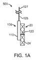
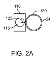
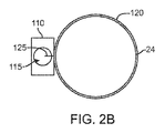
図1〜2を参照すると、ホルダ100と医療デバイス20とを含むシステム500が示されている。医療デバイス20は、自己拡張式フレーム24を有する。医療デバイス20は、被験者の弁に埋め込むように構成することができる。実施形態において、医療デバイス20は、無縫合外科用心臓弁のような補綴心臓弁である。ホルダ100は、収縮構成で埋込可能医療デバイスのフレーム24を保持し、かつフレームの拡張を制御するように構成される。図1A(側面図)及び2A(上面図)では、フレーム24は収縮構成にあり、図1B(側面図)及び2B(上面図)では、フレーム24は拡張構成にある。
i. Generalized Holding or Transport System and Device Overview Referring to FIGS. 1-2, a
ホルダ200は、制御可能に収縮可能かつ拡張可能なループ120を含む。本明細書に使用する場合に、「収縮可能かつ拡張可能なループ」は、ループによって定められる開口部のサイズをより小さく(収縮する)又はより大きく(拡張する)ことができることを意味する。ループ120は、ループの収縮又は拡張がフレームの収縮又は拡張を制御するように自己拡張式フレーム24の少なくとも一部分の回りに配置される。本発明の開示の目的に対して「フレームの収縮又は拡張の制御」は、フレームの少なくとも一部分の収縮又は拡張の制御を含む。
フレームがホルダ又はホルダを含むシステムによって収縮することができる程度は、一部のフレームが小さすぎる直径までクリンピングされる場合に損傷を受ける場合があるので制限される可能性がある。あらゆる適切なクリンプ制限機構を使用することができる。例えば、ループが収縮することができる程度を制限するクリンプ制限器を使用することができる。更に別の例として、フレームを収縮することができる程度を制限するクリンプ制限器を使用することができる。クリンプ制限器の一部の例は、より特定の実施形態に関してより詳細に以下に説明する。 The degree to which a frame can be shrunk by a holder or a system that includes a holder can be limited as some frames can be damaged if crimped to a diameter that is too small. Any suitable crimp limiting mechanism can be used. For example, a crimp limiter that limits the degree to which the loop can contract can be used. As yet another example, a crimp limiter can be used that limits the degree to which the frame can be deflated. Some examples of crimp limiters are described in more detail below with respect to more specific embodiments.
一部の実施形態において(例えば、図1〜2に示すように)、ループ120は、コード125の一部分から形成される。コード125の一部分は、コード125の端部127が延長部材110を超えて延びるようにホルダの延長部材110内で導管115を通って延びる。コード125にかかる張力の維持は、ループ120を比較的収縮した状態に保持する(例えば、図1A及び2A)。コード125にかかるいずれの張力の解除も、埋込可能医療デバイス20のフレーム24が自己拡張するので、ループ120が拡張することを可能にする(例えば、図1B及び2B)。
In some embodiments (eg, as shown in FIGS. 1-2), the
ここで図3を参照すると、ホルダ100と自己拡張式フレーム24を有する埋込可能医療デバイス20とを含むシステム500の実施形態側面図が示されている。図3に示す実施形態は、図1Aに示す実施形態に類似しており、同様の番号は同様の構成要素を指す。図3に示す実施形態において、ホルダ100は、デバイスのフレーム24の拡張を制御するための3つのループ120、130、140を含む(例えば、図1〜2にループ120に関して上述したように)。ループ120、130、140は、各々独立に収縮可能かつ拡張可能にすることができ、又はループのうちの1つ又はそれよりも多くは、単独で収縮可能又は拡張可能にすることができる(例えば、1つのループの収縮が別のループの収縮をもたらす)。1つの位置(例えば、フレーム中央の円周の周り)におけるフレームの収縮がフレームの他の部分の拡張(例えば、上部又は底部の拡張)を防止するのに十分でないデバイスと共に使用する時に、1つよりも多いループを有利に使用することができる。
With reference now to FIG. 3, there is shown a side view of an embodiment of a
図3に示す実施形態に示すように、各ループ120、130、140は、コード125、135、145の一部である。コード125、135、145は、延長部材110の1つ又はそれよりも多くの導管(図示せず)を通って延びる。一部の実施形態において、ループの全ては、同じ導管を通って延びる。一部の実施形態において、各コードは、個別の導管を通って延びる。一部の実施形態において、単独で収縮可能かつ拡張可能であるループのコードは、同じ導管を通って延びる。
As shown in the embodiment shown in FIG. 3, each
ホルダは、1つ(図1〜2に示すように)、2つ、3つ(例えば、図3に示すように)、4つ、5つ、又はそれよりも多くのようなあらゆる適切な数のループを含むことができることは理解されるであろう。ループのいずれか1つ又はそれよりも多くは、独立に又は単独で収縮可能かつ拡張可能にすることができる。一部の実施形態において、少なくとも1つのループは、少なくとも1つの他のループに対して独立に収縮可能かつ拡張可能である。 The holder can be any suitable number, such as one (as shown in FIGS. 1-2), two, three (eg, as shown in FIG. 3), four, five, or more. It will be understood that multiple loops can be included. Any one or more of the loops can be made retractable and expandable independently or alone. In some embodiments, at least one loop is independently contractible and expandable with respect to at least one other loop.
ここで図4A〜Bを参照すると、ホルダ100と拡張可能なフレーム24を有するデバイス20とを含むシステムの実施形態の側面図が示されている。図4A及び4Bに示すシステムは、ホルダの延長部110が少なくとも部分的にフレーム24の中心開口部内に位置決めされることを除いて、図1A及び1B(同様の番号は同様の構成要素を指す)に示す実施形態に類似している。延長部110は、図示したようにフレーム24の縦軸線と位置合わせすることができる。これに代えて、延長部110は、フレームの縦軸線からオフセットすることができ、ある角度だけ軸線から偏位する場合がある等々である。例えば、図1Aに示す実施形態において、延長部は、フレーム24の縦軸線からオフセットされてこれに平行である。
4A-B, a side view of an embodiment of a system that includes a
図4Bに示すように、ループ120又はループを形成するコード125のいずれかの延長部110の一部分がフレーム24の中心開口部内に位置決めされる時に、ループ又はコードの一部分は、ループ120がフレーム24の少なくとも一部分を拘束することができるようにフレームの中心開口部からフレームの縁部まで延びる。
As shown in FIG. 4B, when a portion of the
ホルダは、1つ、2つ、3つ、4つ、5つ、又は6以上のあらゆる適切な数の延長部を含むことができる。一部の実施形態において、ホルダは、各ループ又はコードに対して1つの延長部を有する。一部の実施形態において、ホルダは、ループ又はコードよりも多くの延長部を有し、1つよりも多いコードが、少なくとも1つの延長部を通過する。上で考察したように、各延長部は、あらゆる適切な数の導管を有することができる。一部の実施形態において、延長部は、延長部を通過する各コードが個別の導管を通過するように十分な数の導管を有する。一部の実施形態において、1つよりも多いコードは、与えられた延長部の導管を通って延びる。 The holder can include any suitable number of extensions, such as 1, 2, 3, 4, 5, or 6 or more. In some embodiments, the holder has one extension for each loop or cord. In some embodiments, the holder has more extensions than loops or cords, and more than one cord passes through at least one extension. As discussed above, each extension can have any suitable number of conduits. In some embodiments, the extension has a sufficient number of conduits such that each cord passing through the extension passes through a separate conduit. In some embodiments, more than one cord extends through a conduit of a given extension.
ここで図5を参照すると、ホルダ100と自己拡張式フレーム24を有する埋込可能医療デバイス20とを含むシステム500の実施形態が示されている。図示のホルダ100は、第1の延長部材110及び第2の延長部材150を有する。延長部材110、150は、フレーム24の縦軸線からオフセットされてこれに実質的に平行であり、フレームに対して外部に位置決めされる。これに代えて、延長部材は、少なくとも一部分がフレームの中心開口部内にあるように、又は1つがフレーム内にあり、別のものがフレームの外部にあるように位置決めすることができる。上で考察したように、いずれの与えられた延長部材も、フレームの縦軸線と位置合わせされ、フレームの縦軸線からオフセットされてこれに平行であり、又は縦軸線からある角度で延びることができる等々である。
Referring now to FIG. 5, an embodiment of a
図5に示す実施形態において、第1のループ120は、第1の延長部材110の導管を通って延びる第1のコード125の一部であり、結果的にコード125の端部127は、第1の延長部材110を超えて延びるようになる。第2のループ130は、第2の延長部材150の導管を通って延びる第2のコード135の一部であり、結果的にコード135の端部137は、第2の延長部材110を超えて延びるようになる。ホルダ110は、第1のコード125及び第2のコード135の一部分が延びるアダプタ160を含む。アダプタ160は、延長部120、150の一方又は両方とは個別の構成要素又はそれと同じ構成要素の一部とすることができる。アダプタ160は、好ましくは、第1の延長部材120及び第2の延長部材150の相対位置を保持する。アダプタ160はまた、搬送デバイスのシャフトと協働的に嵌合するように構成することができ、アダプタ160は、様々な実施形態において以下で考察する。
In the embodiment shown in FIG. 5, the
ここで図6を参照すると、図5に示すアダプタ160の上面図が示されている。アダプタ160は、アダプタ160を通って延びる第1の内腔162及び第2の内腔164を有する。図5及び6の両方を参照すると、第1のコード125は、アダプタ160の第1の内腔162を通って延び、第2のコード135は、アダプタの第2の内腔164を通って延びる。
Referring now to FIG. 6, a top view of the
アダプタは、コードが通って延びることができるあらゆる数の内腔を有することができる。一部の実施形態において、アダプタは、全てのコードが通って延びる単一内腔を有する。一部の実施形態において、アダプタは、各コードが個別の内腔を通って延びるのに十分な数の内腔を有する。一部の実施形態において、1つよりも多いコードが、アダプタの内腔を通って延びる。 The adapter can have any number of lumens through which the cord can extend. In some embodiments, the adapter has a single lumen through which all cords extend. In some embodiments, the adapter has a sufficient number of lumens for each cord to extend through a separate lumen. In some embodiments, more than one cord extends through the lumen of the adapter.
ここで図7を参照すると、ホルダ100及びシャフト210が示されている。ホルダは、図6に示すホルダに類似しており、同様の番号で表した識別子は同様の構成要素を指す。図7のホルダ100は、端部127を有する第1のコード125の一部としての第1のループ120と、端部137を有する第2のコード135の一部としての第2のループ130と、第1の延長部材110と、第2の延長部材150と、アダプタ160とを含む。第1の延長部材110は、第1のループ120又はコード125がそこから出る開口部113を含み、第2の延長部材150は、第2のループ130又はコード135がそこから出る開口部153を含む。開口部113、153は、延長部材110、150のあらゆる適切な位置に位置決めすることができ、図7に示す位置は、例示目的に過ぎないことは理解されるであろう。第1のコード125及び第2のコード135は、コードの端部127、137がシャフト210を超えて延びるように延長部材アダプタ及びシャフトを通って延びる。コード125、135の端部部分127、137は、ループ120、130の収縮及び拡張を制御するように構成された1つ又はそれよりも多くの作動機構(図示せず)に結合するように構成される。シャフト210は、コードが通って延びることができる1つ又はそれよりも多くの内腔を含むことができる。
Referring now to FIG. 7, the
シャフトは、あらゆる適切な数の内腔を有することができる。一部の実施形態において、シャフトは、全てのコードが延びる単一内腔を有する。一部の実施形態において、シャフトは、各コードが個別の内腔を通って延びるのに十分な数の内腔を有する。一部の実施形態において、1つよりも多いコードが、シャフトの内腔を通って延びる。 The shaft can have any suitable number of lumens. In some embodiments, the shaft has a single lumen through which all cords extend. In some embodiments, the shaft has a sufficient number of lumens for each cord to extend through a separate lumen. In some embodiments, more than one cord extends through the shaft lumen.
ここで図8を参照すると、ホルダ100及び搬送ツール又はシステム200の実施形態が示されている。図8に示す実施形態は、図7に示す実施形態に類似しており、同様の番号は同様の構成要素を指す。図8では、搬送ツール200は、ループ120、130の収縮及び拡張を制御するように構成された張力装置と作動可能に結合された作動要素230、240を有するハンドル220を含む。ハンドル220は、シャフト210又はハンドル220に取り付けられ、シャフト210は、単一構成要素として形成することができる。シャフト210及びハンドル220は、十分に剛性であり、又は十分に剛性の構成要素を有し、ユーザがハンドル又はシャフトを把持して自己拡張式医療デバイスを望ましいインプラント位置に向けることを可能にする。望ましい実施形態において、ハンドルは、一方の作動要素が一方のループを制御することができ、他方の作動要素が他方のループを制御することができるように2つの作動要素230、240(各々独立に個別の張力装置に結合された)を有する。
Referring now to FIG. 8, an embodiment of the
一部の実施形態において、1または2以上のループを、単一作動要素によって制御することができる。 In some embodiments, one or more loops can be controlled by a single actuation element.
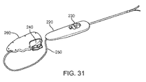
ここで図9を参照すると、ホルダ100及び搬送ツール又はシステム200の実施形態が示されている。図9に示す実施形態は、図7及び8に示す実施形態に類似しており、同様の番号は同様の構成要素を指す。図9では、搬送ツール200は、テザー150を通じてハンドル220に取り付けられた制御ユニット260を含む。制御ユニット260は、ループ120、130の収縮及び拡張を制御するための作動要素230、240(例えば、ハンドル又は制御ユニットに収容することができる張力装置と作動可能に結合された)を含む。図9に示すようなツール200は、人が1つの手で自己拡張式医療デバイス(これはホルダ100によって保持されると考えられる)を位置決めし、別の手で作動要素230、240を通じてループ120、130の収縮及び拡張を制御することを可能にする。これに代えて、1人の個人が、シャフト210又はハンドル220を把持することによって適切なインプラント位置にデバイスを位置付けることができ、別の個人が、制御ユニット260の作動要素230、240を通じてループ120、130を制御することができる。一部の実施形態において、コード(図9には示さず)は、制御ユニット260において作動要素230、240と結合される。一部の実施形態において、コードは、ハンドル又はシャフトの一部である作動アセンブリの一部分と結合され、作動アセンブリのこれらの部分は、制御ユニット260において作動要素230、240を通じて制御される。
Referring now to FIG. 9, an embodiment of the
図1−9に関する以上の考察は、埋め込むことができるデバイス、並びにデバイスを埋め込むためのホルダ及び搬送ツールに関して一般的であることを意図している。図1〜9に示す又これに関して考察した態様、構成要素、又は態様又は構成要素の両方は、互換性があることは理解されるであろう。例えば、図1に関する上記考察も、必要に応じて図9に関する考察に適用することができ、逆も同様である。 The above discussion regarding FIGS. 1-9 is intended to be general with respect to devices that can be implanted, as well as holders and transfer tools for embedding the devices. It will be understood that both the aspects, components, or aspects or components shown in FIGS. 1-9 and discussed in this regard are interchangeable. For example, the above discussion regarding FIG. 1 can also be applied to the discussion regarding FIG. 9 as needed, and vice versa.
一部の実施形態において、本明細書に説明するようなホルダ又は搬送システムを使用して埋込可能なデバイスは、被験者の自然弁に埋め込むように構成された自己拡張式デバイス又は自己拡張式構成要素を有するデバイスである。様々な実施形態において、デバイスは、自然弁の環帯と位置合わせされるように構成された環状部分を有するフレームを含む。一部の実施形態において、埋め込むべきデバイスは、補綴心臓弁である。 In some embodiments, a device implantable using a holder or delivery system as described herein is a self-expanding device or self-expanding configuration configured to be implanted in a subject's natural valve A device having elements. In various embodiments, the device includes a frame having an annular portion configured to be aligned with a natural valve annulus. In some embodiments, the device to be implanted is a prosthetic heart valve.
一部の実施形態におけるフレームは、本明細書に説明するように、ホルダ又は搬送システムを使用して制御方式で圧潰構成から拡張構成まで拡張可能である。そのような一部の実施形態における拡張構成では、フレームの環状部分は、自然弁の環帯と係合するように構成される。フレームが自然弁の環帯と適正に位置合わせされていない場合に、埋め込み手順中にフレームを再位置決めすることができるように、フレームは、本明細書に説明するホルダ又は搬送システムを使用して拡張構成から少なくとも部分的に潰れた構成に少なくとも部分的に潰れるように構成することができる。 The frame in some embodiments can be expanded from a collapsed configuration to an expanded configuration in a controlled manner using a holder or transport system, as described herein. In an expanded configuration in some such embodiments, the annular portion of the frame is configured to engage a natural valve annulus. The frame uses a holder or transport system as described herein so that the frame can be repositioned during the implantation procedure if the frame is not properly aligned with the natural valve annulus. It can be configured to at least partially collapse from an expanded configuration to an at least partially collapsed configuration.
一部の実施形態において、フレームは、埋め込まれた時に環状部分よりも上方に位置決めされるフランジを有し、フランジは、収縮可能かつ拡張可能である。フランジは、環帯の周りにデバイスを係止するように構成された凹面形状部分の一部とすることができる。一部の実施形態において、ホルダの少なくとも1つのループは、フランジの少なくとも一部分の周りに位置決めされ、埋め込み手順中にフランジの拡張を制御する。 In some embodiments, the frame has a flange that is positioned above the annular portion when implanted, the flange being retractable and expandable. The flange may be part of a concave shaped portion configured to lock the device around the annulus. In some embodiments, at least one loop of the holder is positioned around at least a portion of the flange to control expansion of the flange during the implantation procedure.
II.弁の解剖学的特徴及び補綴心臓弁の例
患者の心臓弁に補綴心臓弁を搬送するように有利に使用することができるホルダ及び搬送システムの特定の実施形態を説明する前に、心臓弁デバイス構成要素及び心臓弁生体構造の概要を図10〜19に関して提供する。
II. Example of prosthetic heart valve and valve anatomical features Before describing specific embodiments of a holder and delivery system that can be advantageously used to deliver a prosthetic heart valve to a patient's heart valve, a heart valve device An overview of the components and heart valve anatomy is provided with respect to FIGS.
図10A及び10Bは、一般的に、心臓弁1の一例示的実施形態を示している。図10に示すように、弁1は、遠位流出端2、複数のリーフレット3、及び近位流入端4を含む。典型的な弁は、図10Aに示すように、その弁が収縮期中に又は筋肉収縮に応答して広く開き、弁口にわたって前方流れを遮らないことを可能にすることができるという点で圧潰可能な管と同様に機能する。対照的に、前方流れは、収縮期又は収縮の終了時に減速するので、管の壁は、図10Bに示すように血管壁への取り付け部位間の中心に押し込まれ、弁は完全に閉じる。
10A and 10B generally illustrate one exemplary embodiment of a
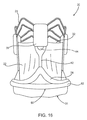
図11A、11B、及び11Cは、典型的な大動脈弁の生体構造を示している。特に、図11Aは、3つの弁洞を有する閉じた弁の上面図を示し、図11Bは、閉じた弁の斜視断面図を示し、かつ図11Cは、血管壁の外側からの図である。 11A, 11B, and 11C show typical aortic valve anatomy. In particular, FIG. 11A shows a top view of a closed valve with three valve sinuses, FIG. 11B shows a perspective cross-sectional view of the closed valve, and FIG. 11C is a view from the outside of the vessel wall.
弁交換システム及びデバイスの設計における1つの考慮は、交換すべき弁のアーキテクチャである。例えば、僧帽及び三尖心臓弁は弁洞を持たないのに対して、大動脈及び肺心臓弁は弁洞を有する。弁洞12は、自然弁リーフレットを取り囲む血管壁の膨張である。典型的には、大動脈弁では、各自然弁リーフレットは、リーフレットと血管壁の間に接触を許さずにピーク流れでリーフレットの最大開口部を可能にする個別の洞バルジ12又は空洞を有する。図11A、11B、及び11Cに示すように、洞12の程度は、一般的に、交連11、血管壁13、流入端14、及び流出端15によって定められる。洞空洞間の近位交差点は、交連11を定める。
One consideration in the design of valve replacement systems and devices is the architecture of the valve to be replaced. For example, mitral and tricuspid heart valves do not have a sinus, while aortic and pulmonary heart valves have a sinus. The
図11B及び11Cも、流入端14及び流出端15の両方において洞の狭い直径を示し、従って、洞領域の流入及び流出環帯を形成する。従って、弁洞は、自然区画を形成し、リーフレットと血管壁の間の接触を防止することによって弁の作動をサポートし、これは、次に、リーフレットの接着をもたらし、及び/又はリーフレットの有害な摩耗及び引裂をもたらす場合がある。弁洞はまた、閉じたリーフレットにかかる流体圧力が最大である閉鎖中に弁リーフレットに課せられる応力条件を共有するように設計される。弁洞は、高逆流圧力の条件下でリーフレットのそうでなければ突然の閉鎖をやわらげる流れによる望ましい流体力学を更に生成する。最後に、洞は、洞空洞内に位置決めされたあらゆる血管への一定流量を保証する。
11B and 11C also show the narrow diameter of the sinus at both the
図12は、弁洞領域の形状及び相対寸法の概略表現である。図12に示すように、弁洞領域は、洞の実サイズに関係なく実質的に一定のままである特定の相対寸法によって特徴付けられる。一般的に、洞の寸法は、洞空洞16の中心においてその最大であるが、流入端14の近くの流入環帯17及び流出端15の近くの流出環帯18の両方において洞領域の顕著な狭窄が存在する。更に、洞19の高さ(すなわち、流入環帯17と流出環帯18の間の距離)は、その全体寸法に実質的に比例したままである。従って、洞領域は、弁を一意的に収容するようになっている特定の不変特徴を有する解剖学的区画を形成することは明らかである。本明細書に開示するシステム及びデバイスは、交換弁機能及び位置決めのための自然洞領域のこれらの解剖学的特徴を利用するように設計することができる。
FIG. 12 is a schematic representation of the shape and relative dimensions of the sinus region. As shown in FIG. 12, the valve sinus region is characterized by specific relative dimensions that remain substantially constant regardless of the actual size of the sinus. In general, the size of the sinus is its maximum at the center of the
図13は、米国公開特許出願第2010/0168844号明細書(この出願は、それが本明細書に提示する開示に反しない範囲でこれによりその全体が引用によって組み込まれる)により詳細に説明されている弁交換システム20の斜視図であり、これは、以下により詳細に説明する弁の一般的特徴を含む。そのような弁、並びに図4に示す弁は、交換弁22、弁支持構造又はフレーム24、及び弁カフ26を含む。交換弁22は、交換弁22が支持構造内にあるようにフレーム24に取り付けることができる。弁支持構造24は、例えば、自然心臓弁のような埋め込み部位に搬送するようになっている拡張可能及び圧潰可能なステント様フレーム構造とすることができる。フレーム24は、自己拡張式又は非自己拡張式のいずれかとすることができ、当業者が認識するように、あらゆる適切な搬送手段を通じてターゲット部位に搬送することができる。弁カフ26は、交換弁22の流入端に取り付け可能であり、弁の周りの弁傍漏出を低減すると同時に埋込部位における埋込後の交換弁22の移動を低下させて安定性を増大させるように構成することができる。
FIG. 13 is described in more detail in US Published Patent Application No. 2010/0168844, which is hereby incorporated by reference in its entirety to the extent that it does not contradict the disclosure presented herein. FIG. 2 is a perspective view of a
図13に示す交換弁22は、三尖弁である。例示的かつ限定しない目的のために、以下の考察は弁22のみを参照し、あらゆるステント又はステントレス交換弁を考えていることは理解されるものとする。同様に、弁フレーム24は、三尖弁を受け入れるように構成すると示されているが、3つ以外のいくつかのリーフレットを有する交換弁が相応に異なる弁支持構造を必要とすることを当業者は認めるであろう。
The
図14は、交換弁22の斜視図であり、交換弁22は、本明細書に説明する弁交換システム20と共に使用可能な3リーフレット交換弁の一例示的実施形態を表している。交換弁22は、近位流入端31及び遠位流出端32を有する弁本体30を含む。弁本体30は、縫い目34によって接合される複数の弁組織リーフレット33を含み、各縫い目34は、2つのリーフレットの接合部によって形成される。交連タブ領域35は、弁本体30の遠位端にある各縫い目34から延びる。弁本体30の流入端31は、扇形又は直線とすることができる周囲縁部を含む。更に、弁本体30の流入端31は、縫い合わせるか又はそれ以外にそれに取り付けることができる補強構造36を更に含むことができる。
FIG. 14 is a perspective view of an
しかし、本明細書に説明する弁交換システム及びデバイスは、図14に示す特定の弁に限定されない。例えば、弁本体30の近位流入端31は、扇形周囲縁部と共に図14に示されているが、他の形状及び構成も考えられ、本発明の開示の意図する範囲にある。
However, the valve replacement systems and devices described herein are not limited to the specific valves shown in FIG. For example, although the
弁リーフレット33は、限定するわけではないが、ポリマー材料、金属材料、及び/又は組織工学材料を含むあらゆる適切な材料で構成することができる。例えば、牛、豚、馬、羊、及び/又は他の適切な動物組織を使用して弁リーフレットを構成することができる。一部の実施形態において、弁リーフレットは、例えば、人又は動物からの心臓弁、大動脈基部、大動脈壁、大動脈尖、心臓周囲組織、血管、腸粘膜下組織、及び臍帯組織などから得られる材料で構成されるか又はそれらから形成することができる。一部の実施形態において、弁リーフレットは、現在利用可能な生体大動脈弁に類似の拡張ポリテトラフルオロエチレン(ePTFE)、馬心膜、牛心膜、又は自然豚弁リーフレットで構成することができる。
The
図15は、弁支持構造24の側面図であり、弁支持構造24は、本明細書に提示する教示に従って弁交換システム20に使用可能な典型的な支持構造の一例示的実施形態を表している。一般的に弁支持構造24は、交連タブ領域35に沿って遠位に及び近位流入端31に沿って近位に弁22を支持するようになっている圧潰可能及び拡張可能な係止構造として設計される。図15に示すように、弁22及び弁カフ26は、支持構造の構造及び特徴に焦点を当てるために弁フレーム24から脱離されている。
FIG. 15 is a side view of the
一部の実施形態において、弁フレーム24は、一般的に、内部に交換弁22を固定することができるほぼ管状構成を有し、流入リム41、支持ポスト42、及び流出リム43を含む。交換弁22は、支持構造24の流入リム41への取り付けによって近位流入端31に、かつ軸線方向に延びるスロット44を通してねじ込まれた交連タブ35を通じて遠位流出端32に固定することができ、これらは、弁支持構造24の流入リム41から流出リム43に縦方向に延びる支持ポスト42に形成される。従って、支持ポスト42の遠位端45は、弁支持構造24の流出リム43と接触するのに対して、支持ポスト42の近位端46は、弁支持構造24の流入リム41と接触する。
In some embodiments, the
図15に示す実施形態において、支持構造24の流出リム43は、一般的にその中にある軸線方向に延びるスロット44で又はその上方で支持ポスト42の間を延びる複数のリングを含むように示されている。流出リム43の複数のリングは、ピーク47及びバレー48を形成する波状又はジグザグパターンで構成され、個々のリングは互いに実質的に平行なままである。流出リム43の複数のリングは、波状又はジグザグパターンによって形成されたバレー48の中心に位置決めされた垂直コネクタ要素49を含むことができる。垂直コネクタ要素49は、フレームの圧縮及び拡張中にフレーム24を安定化させ、弁の歪みを防止するように設計される。垂直要素49は、円筒形弁支持構造24の軸線方向に縦方向に延びる。
In the embodiment shown in FIG. 15, the
図15に示す弁支持構造24の実施形態において、流出リム43は、2つのリングで形成されるが、流入リム41は、支持ポスト42の間を延びる単一リングで形成される。しかし、リングの数は重要ではなく、多くの他の構成が考えられている。
In the embodiment of the
弁支持構造24の流入リム41及び流出リム43の両方は、波状又はジグザグ構成で形成される。弁支持構造の様々な実施形態において、流入リム41は、流出リム43よりも短いか又は長い波長(すなわち、ピーク間の周方向寸法)及び/又は小さいか又は大きい波高(すなわち、ピーク間の軸線方向寸法)を有することができる。流入リム41及び流出リム43の波長及び波高を選択して、実質的な歪みなしで弁支持構造24の均一な圧縮及び拡張を保証することができる。流入リム41の波長を更に選択して、図14に示す交換弁22の扇形流入端31のようなそれに取り付けられた弁の流入端の形状をサポートする。注意すべきは、図15に示すように、弁支持構造24の流入リム41を形成する波状又はジグザグパターンは、垂直支持ポスト42の近位端46が流入リム41のピーク50に接続されるように構成される。同様に、弁支持構造24の流出リム43を形成する波状又はジグザグパターンは、支持ポスト42の遠位端45が流出リム43のバレー48に接続されるように構成される。流出リム43のバレー48に支持ポスト42の遠位端45を位置付けることで、交換弁アセンブリ20の圧縮時に弁支持構造24の内腔内に固定された交換弁22に向けた流出リム43の縦方向延長を防止することができる。その結果、交換弁22と弁支持構造24の間の全部ではないがほとんどの接触が排除される。同様に、流入リム41のピーク50に支持ポスト42の近位端46を位置付けることで、弁組織に向けた流入リム41の縦方向延長を防止することができる。従って、交換弁22及び弁支持構造24の圧縮は、弁の歪み又は損傷をもたらさない。
Both the
図15は、支持ポスト42が、ほぼパドルの形状に構成され、軸線方向スロット44がパドルのブレード51内に延びることを示している。パドルのブレード51は、支持構造24の流出リム43に向けられ、流出リム43の波状又はジグザグパターンのバレー48で流出リム43に接続する。支持ポスト42の重要な機能は、一般的に弁22の安定化、特に、交換弁システム20の圧縮時の弁延伸又は歪みを不可能にするように弁取り付けの点でのあらゆる縦方向延長の防止である。パドル形状支持ポスト42のブレード51は、弁22の交連タブ35に適合するように設計することができる。
FIG. 15 shows that the
支持ポスト42は、支持ポストの近位端46の各側面に対して延びる三角形要素52を更に含む。三角形要素52は、弁カフ26に対して取り付け部位として機能するように設計することができ、これらの機能を失うことなく異なる形状で設計することができる。従って、図15に示す要素52の特定の設計は、弁カフ26の取り付けに対してそれほど重要ではなく、多くの他の設計及び形状が考えられており、本発明の開示の意図する範囲にある。
The
支持ポスト42の数は、ほぼ2〜4の範囲にあり、かつ一般的に交換弁22に存在する交連及びリーフレットの数に依存する。従って、弁支持構造24は、3リーフレット交換弁22に対して3つの支持ポストを含むことができる。弁フレーム24の支持ポスト32は、交換される自然弁の自然交連とほぼ一致するように構造化することができる。
The number of support posts 42 is in the range of approximately 2-4 and generally depends on the number of commissures and leaflets present in the
弁フレーム24は、限定するわけではないが、ステンレス鋼又はニチノールを含むあらゆる適切な材料から形成することができる。弁支持構造24に対して選択された特定の材料は、支持構造が自己拡張式であるか又は非自己拡張式であるかに基づいて決定することができる。例えば、自己拡張式支持構造に対する好ましい材料は、ニチノールのような形状記憶材料を含む。
The
図16は、図13の交換弁デバイス20を示す側面図であり、これは、ここでもまた交換弁22、弁支持フレーム24、及び弁カフ26を含む。図16に示す実施形態に示すように、弁22は、弁フレーム24の流入リム41への取り付けによって近位流入端31に、及び支持ポスト42に形成された軸線方向に延びるスロット44を通じてねじ込まれた交連タブ35を通じて遠位流出端32に固定される。注意すべきは、図16に示す実施形態において認められるように、可撓性24の流出リム43は、管状弁フレーム24の内腔内にある弁リーフレット33の遠位流出端32から縦方向に変位するように構造化することができる。従って、弁リーフレット33とフレーム24の間の接触は回避される。
FIG. 16 is a side view showing the
弁の遠位流出端32で支持ポスト42と接触する交換弁22の交連装着タブ35だけによるフレーム24の内の交換弁22の位置決めは、弁の近位流入端31が弁カフ26によって弁支持構造24の流入リム41から分離される間に、交換弁22のどの部分も弁22の作動中フレーム24が接触しないことを保証し、それによってそうでなければ機械的要素との接触から生じる場合がある弁22に及ぼす摩耗を排除する。
Positioning of the
図16に示すように、弁カフ26は、一般的にスカート60及びフランジ62を含む。図16に示すように、スカート60は、近位流入端31に沿ってなどで弁支持構造24の外面を覆うように構造化することができる。特に、弁カフ26のスカート60は、それぞれ近位流入端31及び流入リム41の近くの交換弁22及びフレーム24の全周囲に巻き付けられる。更に、図16に示すように、スカート60は、自然弁埋め込み部位に又はその周りに見出される扇形と交換弁22の扇形構成とに実質的に位置合わせされるようにほぼ扇形構成を有することができる。しかし、非扇形スカートを有する弁カフも考えられており、本発明の開示の意図する範囲にあることを当業者は認めるであろう。
As shown in FIG. 16, the
弁カフ26のスカート60は、交換弁22のような交換弁と共に使用する時に多くの利益を提供するように設計される。第1に、スカート60は、例えば、自然弁取り外し手順後に残された石灰化残余物又は弁残余物が交換弁12のどの部分とも接触状態にならないように弁環帯の不規則性から交換弁22の近位流入端31を保護するように機能する。そうでなければ交換弁22と接触する場合に、これらの残余物は、弁への損傷の危険を課すものである。第2に、自然弁環帯に隣接して位置決めされる時に、スカート60は、別の弁密封源を提供し、また弁カフ26が自然弁環帯の不規則性に適合するのを補助する。第3に、弁カフ26が自然弁環帯に隣接して位置決めされた時に、スカート60は、弁カフの中への組織内方成長を可能にする。そのような組織内方成長は、弁カフ26によって提供されるシールを改良するだけではなく、弁カフを自然弁環帯に固定し、埋め込み後に交換弁システム20の移動を最小にするのにも役立つ。弁カフ26のスカート60は、当業者が認識するように、以前に考察したもの以外の追加の利益を提供することができる。
The
図16に示すように、弁カフ26のフランジ62は、弁の全周囲で交換弁デバイス20から突出するようにスカート60に結合されかつ構成される。交換弁システム20が埋め込み部位に搬送されて配備される時に、弁支持構造24は、埋め込み部位において自然組織に対してフランジ62を押圧する半径方向力を弁カフ26内に働かせ、それによってシールを生成し、大動脈内の交換弁デバイス20の弁傍漏出及び移動を防止する。例えば、弁支持構造24が形状記憶金属から形成される実施形態において、半径方向力は、埋め込み部位に配備した後に拡張形態に「跳ね返る」支持構造から生じる場合がある。
As shown in FIG. 16, the
弁カフ26のフランジ62は、交換弁22の近位流入端31と自然弁部位の環帯の間にシールを形成するように構成される。一部の実施形態において、1つ又はそれよりも多くの自然弁構造が、交換弁デバイス20の埋め込み前に患者の身体から取り外される場合に、不規則性が自然弁部位の環帯の周りに存在する場合がある。これらの不規則性は、例えば、自然弁の抽出物から残された自然石灰化又は弁残余物の結果であるとすることができる。環帯の周りの不規則性は、これらが弁傍漏出に寄与する可能性があるので問題である場合がある。
The
過去には、不規則性が存在した時の自然弁環帯と交換弁の間に密封を維持することは困難であった。しかし、弁カフ26のフランジ62は、自然弁環帯の周りの不規則性に適合し、従って、交換弁22と自然弁環帯の間のシールを改良するように構造化される。その結果、交換弁の周りの弁傍漏出は、減少又は排除することができる。
In the past, it has been difficult to maintain a seal between the natural annulus and the exchange valve when irregularities existed. However, the
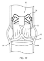
図17は、大動脈弁内に位置決めされた交換弁システム20の図であり、交換弁システム20は自然弁環帯64を含む。図17に示すように、弁フレーム24は、自然弁環帯64内で拡張されており、それによって自然弁環帯64に対して弁カフ26のフランジ62を押圧し、埋め込み部位から交換弁22の弁傍漏出及び移動を防止又は少なくとも最小にするように、交換弁22と自然弁環帯64の間に密封を形成する。従って、自然環帯64に接触したフランジ62により、弁カフ26は、ガスケットとして作用して、交換弁システム20と自然弁環帯64との間で接合部を密封する。
FIG. 17 is an illustration of the
一実施形態において、自然弁環帯内に埋め込む前に接着剤を弁カフ26に塗布することができる。例えば、あらゆる適切な生体適合性接着剤をスカート60及びフランジ62の外面に塗布して、弁環帯の周囲組織に対して弁カフ26を密封するのを補助する。必須の構成要素ではないが、生体適合性接着剤は、更に弁傍漏出を低減するために、より密封を提供するのを補助することができる。
In one embodiment, an adhesive can be applied to the
他の実施形態において、弁カフ26のフランジ62は、自然弁環帯で密封を生成するのを補助するフランジ内に配置された記憶形状又は変形可能な材料で構成することができる。特に、記憶形状又は変形可能な材料は、弁カフ26が埋め込み部位に適正に位置決めされる時に拡張することができるように構造化される。このタイプの弁カフフランジは、弁支持構造が自己拡張式タイプか又は非自己拡張式タイプかに関係なく利用することができる。
In other embodiments, the
一部の実施形態において、弁カフ26のスカート60及びフランジ62の両方は、布又は織材から形成することができる。織物は、限定するわけではないが、ポリエチレンテレフタレート、ポリテトラフルオロエチレン(PTFE)、又は他の生体適合性材料のような織りポリエステルを含むあらゆる適切な材料を含むことができる。
In some embodiments, both the
弁交換システム20を組み立てる一例示的実施形態において、スカート60及びフランジ62は、弁カフ26を形成するように互いに結合された個別の構成要素として形成される。特に、スカート60は、縫合などによるあらゆる適切な方式で弁支持フレーム24の周りに位置決めされてこれに結合することができる。例えば、各スカート取り付け部分63は、弁フレーム24の対応する支持ポスト42に巻き付けることができる。次に、スカート取り付け部分63は、例えば、支持ポスト42の各々の近位端46の近くの三角形取り付け部位52に縫合することができる。次に、フランジ62は、スカート60の周りの望ましい位置に位置決めされ、縫合などによってあらゆる適切な手段によってスカートに結合することができる。次に、交換弁22は、フレーム24の内側内腔内に位置決めし、交換弁22の交連タブ部分35を対応する軸線方向に延びるスロット44を通じて支持ポスト42の中に挿入することができる。フレーム24の流入リム41の周りに周方向に位置決めされた弁カフ26のスカート60は、次に、交換弁22の近位流入端31に巻き付けられ、例えば、縫合糸で弁に取り付けることができる。取り付けられると、スカート60及びフランジ62は、交換弁22と自然弁環帯の間に緊密なガスケット様シール面を生成するように構造化される。上述の事項は、本発明の開示に従って弁交換システムを組み立てる1つの方法の例示的実施形態のみを表している。従って、当業者が認識するように段階の数及び順序に修正を行うことができる。
In one exemplary embodiment of assembling the
ここで図18Aを参照すると、人工弁のフレーム24は、例えば、「凹面着地ゾーンを有する係止構造」という名称の米国特許出願公開第2010/0100176号明細書に説明するような凹面着地ゾーンを含むことができ、この特許出願公開は、それが本明細書に提示する開示に反しない範囲でこれによりその全体が引用によって組み込まれる。図18Aのフレーム24は、線A−Aに沿って切断されて平坦に置かれていると示されている。図18Aのフレーム24は、本明細書に説明する弁交換システム20に使用可能な典型的な固定又は支持構造の一例示的実施形態を表している。一般的に、フレーム24は、交連領域に沿って遠位に及び近位流入端に沿って近位に弁を支持するようになっている圧潰可能及び拡張可能な係止構造として設計される。図18に示すように、弁は、支持構造の構造及び特徴に焦点を当てるために弁フレーム24から脱離されている。
Referring now to FIG. 18A, the
フレーム24は、内部に交換弁を固定することができるほぼ管状構成を有し、流入リム41、支持ポスト42、及び流出リム43を含む。交換弁は、支持構造24の流入リム41への取り付けによって近位流入端31に、かつ軸線方向に延びるスロット44を通じてねじ込まれた交連タブ35を通じて遠位流出端32に固定することができ、これらは弁支持構造24の流入リム41から流出リム43に縦方向に延びる支持ポスト42に形成される。従って、支持ポスト42の遠位端45は、弁支持構造24の流出リム43と接触するのに対して、支持ポスト42の近位端46は、フレーム24の流入リム41と接触する。
The
図18に示すように、支持フレーム24の流出リム43は、一般的に、その中にある軸線方向に延びるスロット44で又はその上方で支持ポスト42の間を延びる単一ワイヤリング又はレールを含むように示されている。流出リム43は、ピーク47及びバレー48を形成する波状又は正弦波パターンから構成される。しかし、リングの数は重要ではなく、多くの他の構成が考えられており、様々なパターンの単一、二重、及び三重構成などで利用することができる。流入リム41は、遠位流入ワイヤリング49及び近位流入ワイヤリング51を含む二重ワイヤリング又はレールを含むと示されている。遠位流入ワイヤリング49及び近位流入ワイヤリング51は、ピーク47及びバレー48を形成する波状又は正弦波パターンから構成される。図示のように、二重ワイヤレールは、近位流入ワイヤリング51のピークが遠位流入ワイヤリング51のトラフと接続するように構成され、従って、ダイヤモンドパターンを形成するが、五角形、六角形、矩形のいかなるいくつかの望ましい形状を達成することができ、これらの全ては、本明細書に提示する開示の範囲にある。
As shown in FIG. 18, the
流入リム41は、遠位及び近位流入ワイヤリング49、51がこれらから軸線方向に接続して延びるところに位置決めされた指状要素53を含む。指状要素53は、流入リム41を覆って織物を係止して組織内方成長を可能にすることができる織物への追加の支持を与えるように設計される。
The inflow rim 41 includes finger-like elements 53 positioned where distal and proximal inflow wire rings 49, 51 extend axially from them. The finger elements 53 are designed to provide additional support to the fabric that can cover the
図18Aに示す支持フレーム24の実施形態において、流出リム43は単一リングで形成されるが、流入リム41は、支持ポスト42の間を延びる二重リングで形成される。しかし、リングの数は、変化することができ、多くの他の構成が考えられている。
In the embodiment of the
フレーム24の流入リム41及び流出リム43の両方は、波状又は正弦波状構成で形成することができる。弁支持構造の様々な実施形態において、流入リム41は、流出リム43よりも短いか又は長い波長(すなわち、ピーク間の周方向寸法)又は小さいか又は大きい波高(すなわち、ピーク間の軸線方向寸法)を有することができる。流入リム41及び流出リム43の波長及び波高を選択して、実質的な歪みなしに支持フレーム24の均一な圧縮及び拡張を保証することができる。流入リム41の波長を更に選択して、図18に示す交換弁22の扇形流入端31のようなそれに取り付けられた弁の流入端の形状を支持することができる。注意すべきは、図18Aに示すように、フレーム24の流入リム41を形成する波状又は正弦波パターンは、垂直支持ポスト42の近位端46が流入リム41のトラフ48に接続されるように構成することができる。同様に、支持構造24の流出リム43を形成する波状又は正弦波状パターンは、支持ポスト42の遠位端45が流出リム43のピーク47で接続されるように構成することができる。この配置は、搬送する前に弁がその半径方向クリンプ状態にある時に遠位流入ワイヤリング及び近位流入ワイヤリングが互いに移動することを可能にし、従って、生体心臓弁への潜在的損傷を防止する。
Both the
図18Aに示す実施形態において、支持ポスト42の遠位端45は、ほぼパドルの形状に構成され、軸線方向スロット44は、パドルのブレード51内で内部に延びる。パドルのブレード51は、支持構造24の流出リム43に向けられ、流出リム43の波状正弦波状パターンのピークで流出リム43に接続する。支持ポスト42は、一般的には弁を安定化し、特に、交換弁システムの圧縮時に弁延伸又は歪みを不可能にするように弁取り付けの点における縦方向延長の防止を安定化する。パドル形状支持ポスト42のブレード51も、弁の交連タブに適合するように設計される。
In the embodiment shown in FIG. 18A, the
支持ポスト42の数は、存在する場合に、ほぼ2〜4の範囲にあり、かつ弁洞に存在する交連ポストの数によって決定される。従って、一部の実施形態において、弁支持構造24は、3つの自然交連を特徴付ける自然弁を有する3リーフレット交換弁に対して3つの支持ポストを含む。フレーム24の支持ポスト42は、存在する場合に、自然弁の自然交連とほぼ一致するように構造化することができる。
The number of support posts 42, if present, is in the range of approximately 2-4 and is determined by the number of commissure posts present in the valve sinus. Thus, in some embodiments, the
ここで、図18Bには、凹面着地ゾーン60を示す流入リム41の断面図が示されている。図示のように、遠位流入リング49のピーク47及び近位流入リング51のトラフ48は、配備すると流入リム41がC字形の断面を形成するように外向きに広がる。流入リム41の断面積61、又は換言するとフレームの凹面部分は、直接に自然環帯に対応する。流入リムのフレームは、環帯の上及び下に重なる広がったレール47、48を有する自然環帯と係合する。配備すると、自己拡張式フレームによってもたらされる半径方向力は、適切な位置に弁を保持する。
Here, FIG. 18B shows a cross-sectional view of the
凹面着地ゾーン61は、実質的に弁傍漏出を防止する。弁傍漏出は、流入リム41が実質的に環帯の近位に及び遠位に固定されることを保証することによって低減し、すなわち、密封を形成することができる。凹面着地ゾーン60は、外科医が容易に生体心臓弁を環帯に置くことを可能にし、従って、患者が手術に費やす時間を最小にする。
The concave landing zone 61 substantially prevents paravalvular leakage. Paravalvular leakage can be reduced, i.e., form a seal, by ensuring that the
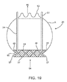
図19は、自然弁解剖学的構造内に位置決めされた交換弁システム20であり、自然弁解剖学的構造は、流入環帯64及び流出環帯66を含む。図10に示すように、図18Aの管状係止構造24は、自然弁位置の洞空洞内で拡張しており、それによって自然弁生体構造の流入環帯64に対して流入リム41を押圧し、交換弁システム20と自然弁生体構造の間に密封を形成する。より具体的には、配備すると、流入リム41は、図18B及び10で認められるように、断面凹面着地ゾーン60において実質的にC字形を有する。遠位流入リング49は、環帯の遠位側に当接するが、近位流入リング51は、自然環帯の近位側に当接する。凹面着地ゾーン60は、埋め込み部位からの交換弁システム20の弁傍漏出及び移動を防止又は最小にする。従って、流入環帯64に接触した流入リング41により、凹面着地ゾーン60は、ガスケットとして作用し、交換弁システム20と自然生体構造の間の接合部を密封する。典型的には、流入リング41は、織物で覆われて時間と共に組織内方成長を刺激し、適切な位置に交換心臓弁を固定する。織物は、限定するわけではないが、織ポリエステル、ポリエステルベロア、ポリエチレンテレフタレート、ポリテトラフルオロエチレン(PTFE)、又は他の生体適合性材料を含むあらゆる適切な材料を含むことができる。弁アセンブリは、氷中でクリンピングされ、搬送システムの中に装填され、かつ大動脈弁位置の中に配備することができる。係止構造の自己拡張式特性は、埋め込み後に弁を適切な位置に保持するのに必要な半径方向強度を提供する。
FIG. 19 is a
上記開示は3リーフレット交換弁デバイス20に着目したが、本発明の開示による弁カフは、限定するわけではないが、米国特許出願第10/680,071号明細書、米国特許出願第11/471,092号明細書、及び米国特許出願第11/489,663号明細書を含むほぼ類似の構造のあらゆるタイプの交換弁と共と共に使用することができ、これらは、本明細書に提示する開示に反しない範囲でこれによりその全体が本明細書に組み込まれる。従って、本明細書に開示する弁カフ概念は、本発明の開示の精神及び範囲から逸脱することなくいくつかのリーフレットを有する多くの他のタイプの交換弁で機能するように構成された弁カフに適用することができる。
Although the above disclosure has focused on the three leaflet
更に、上記開示は、流入リム41、流出リム43、及び3つの支持ポスト42を有するフレーム24に焦点を当てるが、この特定の弁支持構造は、単に例示的な目的のために説明するものであり、限定するものではない。従って、本発明の開示による弁カフは、当業者が認識するように、あらゆるほぼ管状のステント状の弁支持構造と共に使用することができる。
Furthermore, while the above disclosure focuses on a
本明細書に説明する搬送システム及び関連のデバイスに使用することができる補綴心臓弁の追加の設計は、2013年6月3日出願の米国特許仮出願第61/819,486号明細書に開示されたそれらの設計、及び本出願と同日出願の代理人整理番号C00005661.USU3を有する「人工弁及び関連の装置、システム、及び方法」という名称の米国特許出願第14/268,494号明細書に開示されたものを含み、これらの特許出願は、これらが本明細書に提示する開示に反しない範囲でこれらのそれぞれの全体が引用によってこれにより各々本明細書に組み込まれる。心臓弁は、例えば、(i)2014年1月23日出願の米国特許仮出願第61/930,851号明細書、(ii)2013年5月3日出願の米国特許仮出願第61/819,486号明細書、及び(iii)本出願と同日出願の代理人整理番号C00007020.USU2を有する「弁に埋め込むための医療デバイス及び関連の方法」という名称の米国特許出願第14,268,925号明細書に開示するようなインプラントを容易にし、インプラント深さ又は向きに関する視覚フィードバックを提供するようなマーキングを有することができ、これらの特許出願の各々は、これらが本明細書に提示する開示に反しない範囲でこれらのそれぞれの全体が引用によってこれにより本明細書に組み込まれる。 Additional designs of prosthetic heart valves that can be used in the delivery system and related devices described herein are disclosed in US Provisional Application No. 61 / 819,486, filed June 3, 2013. Their designs, and attorney docket number C00005661. Including those disclosed in US patent application Ser. No. 14 / 268,494 entitled “Prosthetic Valves and Related Devices, Systems, and Methods” with USU3, which are incorporated herein by reference. Each of which is hereby incorporated by reference in its entirety, to the extent that it does not contradict the disclosure presented in. The heart valve is, for example, (i) US provisional application 61 / 930,851 filed January 23, 2014, (ii) US provisional application 61/819 filed May 3, 2013. 486, and (iii) Attorney Docket No. C0000007020. Facilitates an implant as disclosed in US Patent Application No. 14,268,925 entitled "Medical Device and Related Method for Implantation in a Valve" with USU2 and provides visual feedback regarding implant depth or orientation Each of these patent applications may be incorporated herein by reference in their entirety, to the extent that they do not contradict the disclosure presented herein.
実施形態において、本明細書に説明する交換弁システムは、無縫合弁システムである。勿論、縫合糸も、そのようなシステムに使用することができる。無縫合交換弁システムの利点は、より短い埋め込み手順時間及び低侵襲性埋め込みを含む。現在の無縫合弁システムによる一部の欠点又は知覚する欠点は、弁傍漏出(PVL)の潜在的危険の増加及び耐久性の潜在的欠如を含む。本明細書に提示する設計は、好ましくは、現在の無縫合弁設計の欠点又は知覚する欠点のうちの1つ又はそれよりも多くに対処する。 In embodiments, the exchange valve system described herein is a sutureless valve system. Of course, sutures can also be used in such systems. Advantages of a sutureless replacement valve system include shorter implantation procedure times and minimally invasive implantation. Some or perceived drawbacks with current sutureless valve systems include an increased potential risk of paravalvular leakage (PVL) and a potential lack of durability. The design presented herein preferably addresses one or more of the shortcomings or perceived shortcomings of current sutureless valve designs.
III.補綴心臓弁の保持又は搬送のためのシステム及びデバイス
弁交換システムのためのホルダ及び搬送システムの様々な実施形態を以下に説明する。一部の実施形態において、ホルダ及び搬送システムは、多くの場合、弁搬送システム、特に無縫合人工弁を搬送するための搬送システムに関連付けられた不正確な配置又は不十分な可視化に対する解決法を提供する。
III. Various embodiments of a system for holding or delivering a prosthetic heart valve and a holder and delivery system for a device valve replacement system are described below. In some embodiments, the holder and delivery system often provide a solution to inaccurate placement or inadequate visualization associated with a valve delivery system, particularly a delivery system for delivering a sutureless prosthetic valve. provide.
埋め込み工程に対して重要なものは、弁交換システム及び搬送システムパッキング構成である。一部の実施形態において、弁は、ホルダ、1つ又はそれよりも多くのコード(これらはループ及びテザーを形成するシンチ縫合糸を含むことができる)、及びアダプタと共にパッケージ化され、コードを管理してもつれを防止する。一部の実施形態において、搬送システムは、クリンピング漏斗及びいずれの他の付属品とも個別にパッケージ化される。 What is important for the embedding process is the valve exchange system and the transport system packing configuration. In some embodiments, the valve is packaged with a holder, one or more cords (which can include cinch sutures that form loops and tethers), and an adapter to manage the cords To prevent tangles. In some embodiments, the transport system is packaged separately with the crimping funnel and any other accessories.
以下の図20〜42及び53〜74では、心臓弁、ホルダ、及び搬送システムのいくつかの実施形態を説明する。多くの態様において、図20〜42及び53〜74に関して示され、又は考察された構成要素は、図1〜9に関して上で提示するか又は考察したものに類似し、同様の番号は同様の構成要素を指す。図における異なる番号の使用は、ラベル付けしたシステム、デバイス、又は構成要素が異種であり又は同じであり得ないことを必然的に意味する。 In the following FIGS. 20-42 and 53-74, several embodiments of heart valves, holders, and delivery systems are described. In many aspects, the components shown or discussed with respect to FIGS. 20-42 and 53-74 are similar to those presented or discussed above with respect to FIGS. 1-9, and like numerals refer to like configurations. Points to the element. The use of different numbers in the figures necessarily means that the labeled systems, devices, or components can be heterogeneous or the same.
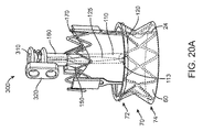
ここで図20A〜Bを参照すると、ホルダ100及び自己拡張式フレーム24を有する補綴心臓弁20の実施形態が示されている。図示の実施形態において、ホルダは、アダプタ160からデバイス20の中心開口部の中に延びる3つの延長部110、150、170を有する。延長部の遠位端部分において、導管(例えば、延長部110の導管113)は、コード(例えば、コード125)の管理のための延長部によって形成される。図示の実施形態において、各延長部のために1つのコードがある。図面からは容易に明らかではないが、各コード(例えば、コード125)は、補綴心臓弁デバイス20の流入領域70の上側部分72の外周の約3分の1付近に配置される。3つのコードは、互いに流入領域70の上側部分72付近に実質的に延びる。そのような実施形態において、コードの全ては、好ましくは、ループ(例えば、第1のコード125のループ120)が張力により互いに収縮又は拡張されるように単独で制御される。図示していないが、単一ループは、上側流入部分72の付近に延びることができ、又は流入領域70の下側部分74又はデバイス又はフレームの流出部分のような他の領域の少なくとも一部分の付近に延びることができることは理解されるであろう。
20A-B, an embodiment of a
一部の実施形態において、人工弁の流入領域付近に位置決めされたコードは、1つ又はそれよりも多くの回数でスカートを通過することができる。コードを通過すると、スカートは、スカートの望ましくない縮みをもたらす場合がある。より小さい咬合(より短い間隔でスカートの内外を通る)によってより少ない縮みが生じる。様々な実施形態において、コードは、2mm又はそれ未満の間隔でスカートの内外を通る。好ましくは、咬合は、フレームの広がった構造の位置で起こり、弁を温める時にコードが滑り落ちるのを防止する。 In some embodiments, a cord positioned near the inflow region of the prosthetic valve can pass through the skirt one or more times. Upon passing through the cord, the skirt may cause an undesirable shrinkage of the skirt. Smaller occlusions (passing in and out of the skirt at shorter intervals) result in less shrinkage. In various embodiments, the cord passes in and out of the skirt with a spacing of 2 mm or less. Preferably, the occlusion occurs at the extended structural position of the frame and prevents the cord from slipping down when warming the valve.
一部の実施形態において、コードは、コードが弁の上部から摺動して外れないような方式で人工弁の流出部分の周りに位置決めされる。一部の実施形態において、コードは、弁流出領域(例えば、交連において)に組み立てられた1つ又はそれよりも多くの織物片を通過する。一部の実施形態において、フック又は広がった部分が、フレームの流出端の中に形成されてコードを取り込む。 In some embodiments, the cord is positioned around the outflow portion of the prosthetic valve in such a manner that the cord does not slide off the top of the valve. In some embodiments, the cord passes through one or more pieces of fabric assembled in the valve outflow region (eg, in commissure). In some embodiments, a hook or widened portion is formed in the outflow end of the frame to capture the cord.
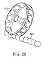
図20Aでは、デバイス20が拡張構成で示されている。図示のように、流入領域70は、フレーム24が、弁洞の環帯の回りのデバイスに係合して密封(スカート60に沿って)するのを補助するように構成されたフランジを形成する流入領域70の上側部分74及び下側部分72で拡張される。図20Bにおいて、デバイスは収縮構成で示されている。
In FIG. 20A, the
コード管理アセンブリ300も図20A〜Bに示されている。コード管理システム300は、コードを巻き付けるスプール310と、コードを取り付けることができるブロック320とを含む。
A
本明細書に説明するほとんどあらゆる実施形態は、図20A及び20Bに示すアセンブリのようなコード管理アセンブリを含むことができる。コード管理アセンブリを含めることで、ホルダを搬送システムに接続する前の出荷及び/又はクリンピング中にコードを管理するように機能することができる。実施形態において、テザー管理構成要素は、テザー縫合糸が巻かれ、テザー接続アダプタを装着するコイルを含む。これは、人工弁がコードの鳥の巣をユーザ管理することなくクリンピングされることを可能にすることができる。コード管理アセンブリは、一部の実施形態において、人工弁が搬送システムに接続する待機状態になっている時は不要にすることができる。 Almost any embodiment described herein can include a code management assembly such as the assembly shown in FIGS. 20A and 20B. Inclusion of a code management assembly can serve to manage the code during shipping and / or crimping prior to connecting the holder to the transport system. In an embodiment, the tether management component includes a coil wound with a tether suture and mounting a tether connection adapter. This can allow the prosthetic valve to be crimped without user management of the cord bird's nest. The code management assembly may be dispensed with in some embodiments when the prosthetic valve is in a standby state for connection to the delivery system.
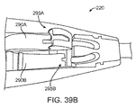
ここで図21A〜Dを参照すると、ホルダ100、補綴心臓弁20、及び搬送システム(又はその一部)が埋め込み手順の様々なステージで示されている。ホルダ100及び補綴心臓弁20は、図20A〜Bに示されているものと同じであり、同様の番号は同様の構成要素を指す。
Referring now to FIGS. 21A-D, the
図21Aに示すように、搬送システムのシャフト210は、ホルダ100のアダプタに結合されている。補綴心臓弁デバイス20は、デバイス20の流入領域の適切な部分がホルダ100及び搬送システムを通じて自然弁の環帯14と位置合わせされるまで自然弁の中に挿入される。弁デバイス20は、収縮(例えば、圧縮)構成で挿入される。張力は、ループ120、130、140を形成するコード上に掛けられ、収縮構成で上側流入部分74を保持する。
As shown in FIG. 21A, the
図21Bに示すように、張力は、ループを形成するコード上に保持されて上側流入部分74を収縮させるが、他の部分(例えば、流入領域及び流出領域80の下側部分72)は、拡張されるか又は拡張することができる。一部の実施形態において、フレームは、フレームを加熱することにより、例えば、温水又は食塩水によって拡張される。デバイス20が適切な深さまで挿入される場合に、流入領域の下側部分72の拡張は、環帯14を過ぎたデバイス20の引き戻しを防止するはずである。流入領域の下側部分72の拡張後にデバイス20が適正に位置決めされるか又は適正に位置決めされるように移動するように思われる場合に、流入領域の上側部分74は、コードの張力を弛めることによって拡張することができ、ループ120、130、140、及び従って上側流入部分74が拡張することを可能にすることができる(図21C)。上側流入部分74及び下側流入部分72の拡張により、デバイス20は、自然弁環帯と確実に係合する。上側流入部分74が拡張した状態で、ホルダ又はその一部分(例えば、延長部110、150、170、及びアダプタは、図21Dに示すようにコード125、135、145にわたって移動する)は、手術ゾーンから移動することができるが、ループ120、130、140は、補綴心臓弁の適切な位置決めを確認することができるようにフレームの周りで弛んだままである。位置決めを確認する場合に、コード125、135、145を切断して、コード(及びループ)を取り除くことができる。補綴心臓弁が不適正に位置決めされたと決定された場合に、搬送ツール及びホルダは、人工弁に向けてコードの上を前進させることができ、上側流入領域は、コードにかかる張力を増加させることによって収縮され、上側流入部分を制限することができ、人工弁は、必要又は所望に応じて再位置決めすることができる。
As shown in FIG. 21B, tension is retained on the cord forming the loop to contract the
収縮構成で人工弁を保持するためのループを形成するコードは、あらゆる適切な材料で作ることができ、あらゆる適切な方式で人工弁と係合することができる。実施形態において、コードは、外科用縫合材料から形成される。取りわけコードは、弁上側流入カフをクリンピングし、張力を受ける時にホルダに剛的に弁を保持し、及び/又はホルダ又は搬送システムが外科用空洞から取り除かれた後でさえも弁でテザーを保持するように機能することができる。コードは、1つ又はそれよりも多くの(例えば、3つの)事例において弁を経由する1つの長い縫合糸、各々1回弁を経由する1つ又はそれよりも多くの(例えば、3つの)縫合糸、又はその組合せとすることができる。いずれかの条件の結果として、弁を出る複数の(例えば、6つの)縫合アームがある。3つの縫合糸の場合に、各テザー縫合糸は、弁外周の1/3、2/3、360°、又はそれよりも多くを封入することができる。そのような場合に、テザーの機能の全ては、1/3の外周封入で達成することができる。従って、追加の封入は、手順の終わりにより大きい縫合糸除去力をもたらすことができるので、各縫合糸を1/3封入に制限することを望ましいとすることができる。高テザー縫合糸除去力は、弁脱落をもたらす可能性がある。従って、一部の実施形態において、高強度の小径縫合糸を好ましいとすることができる[(例えば、3−0極高分子量ポリエチレン(UHMWPE))]。勿論他の縫合糸(例えば、2−0ポリプロピレン、2−0ナイロン、4−0UHMWPEなど)又は他の適切な材料を使用することができる。ループは、下側流入カフ、中心流入カフ、流出レール及びタブ、又はその組合せを経由することができる。 The cord forming the loop for holding the prosthetic valve in the contracted configuration can be made of any suitable material and can be engaged with the prosthetic valve in any suitable manner. In an embodiment, the cord is formed from a surgical suture material. The detachment cord crimps the valve upper inflow cuff, holds the valve rigidly in the holder when under tension, and / or tethers the valve even after the holder or delivery system has been removed from the surgical cavity. Can function to hold. The cord is one long suture that goes through the valve in one or more (eg, three) cases, one or more (eg, three) each through the valve once It can be a suture, or a combination thereof. As a result of either condition, there are multiple (eg, six) suture arms exiting the valve. In the case of three sutures, each tether suture can encapsulate 1/3, 2/3, 360 °, or more of the valve periphery. In such a case, all of the tether function can be achieved with 1/3 outer perimeter encapsulation. Thus, it may be desirable to limit each suture to 1/3 encapsulation, as additional encapsulation can provide greater suture removal force at the end of the procedure. High tether suture removal forces can lead to valve dropout. Thus, in some embodiments, high strength small diameter sutures may be preferred [eg, 3-0 ultra high molecular weight polyethylene (UHMWPE)]. Of course, other sutures (eg, 2-0 polypropylene, 2-0 nylon, 4-0 UHMWPE, etc.) or other suitable materials can be used. The loop can be routed through the lower inflow cuff, the central inflow cuff, the outflow rail and tab, or a combination thereof.
補綴心臓弁のフレーム部分の周りを取り囲むように2つのコード125、135を使用するバージョンが、図22A−Bに示されている。コードは、異なる色(例えば、青色及び赤色)のものとすることができる。コードは、巾着縫合方式(図22A)のような非対称性収集方式、優れた巾着縫合方式(図22B)のような対称性収集方式、又はいずれかの他の適切な方式で構成することができる。
A version using two
コードの数又は縫合様式に関係なく、ホルダは、コードに対して1つ又はそれよりも多くの導管を形成する1つ又はそれよりも多くの延長部を含むことができる。導管は、延長部の長さ又は延長部の一部分のみを通過することができる。例えば、図20〜21に示す実施形態に示すように、導管は、延長部の遠位端部分に形成することができる。導管は、ループの様式に応じてコードの1つ、2つ、又はそれよりも多くのアームを経路指定することができる。図20〜21に示された実施形態において、3つの延長部の各々は、コードの2つのアームを人工弁の3つの突出部の各々に経路指定する。図20〜21に示す実施形態において、3つの延長部(110、150、170)は、好ましくは、120°各々で分離される。 Regardless of the number of cords or the manner of stitching, the holder can include one or more extensions that form one or more conduits to the cord. The conduit can only pass through the length of the extension or a portion of the extension. For example, as shown in the embodiment shown in FIGS. 20-21, the conduit may be formed at the distal end portion of the extension. The conduit can route one, two, or more arms of the cord depending on the manner of the loop. In the embodiment shown in FIGS. 20-21, each of the three extensions routes the two arms of the cord to each of the three protrusions of the prosthetic valve. In the embodiment shown in FIGS. 20-21, the three extensions (110, 150, 170) are preferably separated by 120 ° each.
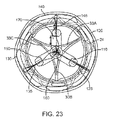
そのような実施形態において、延長部は、好ましくは、ホルダを取り外すか又は弁から再挿入する時に人工弁のリーフレットをクリアするほど十分に広がるが、これらが流出レールを妨げるほど広がらない。図23に例示が提供されており、ここで第1のコード125の2つのアームが第1の延長部110の遠位導管を通じて挿入され、第2のコード135の2つのアームは第2の延長部150の遠位導管を通じて挿入され、第3のコード145の2つのアームは第3の延長部170の遠位導管を通じて挿入される。図23に示す実施形態において、延長部は120°で分離され、ある向きで弁の中に挿入されて3つの弁リーフレット33A、33B、33Cとの接触を回避する。図23に示す実施形態において、コードのループ120、130、140の各々は、人工弁のフレーム24の上側流入部分の約120°周囲に広がる。これに加えて、コードの各々を示す描いた実施形態は、アダプタ160の単一内腔を通って延びる。
In such embodiments, the extensions are preferably wide enough to clear the leaflets of the prosthetic valve when the holder is removed or reinserted from the valve, but not so wide that they interfere with the outflow rail. An illustration is provided in FIG. 23 where the two arms of the
好ましくは、ホルダ延長部は、25〜30lbsの圧縮荷重を累積的に支持するのに十分な剛性である。延長部に管形状又はI形梁形状を取らせることで、延長部の偏向を防止するのを補助する。ホルダはまた、ループが張力を受ける時に、人工弁デバイスと搬送システムとの間で剛性接続するように機能することができ、ホルダは、搬送システムの垂直位置決めを捩り又は調節することによって人工弁の再位置決めを可能にする。脚は、剛性又は半剛性の金属、プラスチック、又はいずれかの他の材料とすることができる。I形梁ホルダ延長部110の例示が、図24に示されている。I形梁形状は、捩り力により良く抵抗するはずである。
Preferably, the holder extension is sufficiently rigid to cumulatively support a compressive load of 25-30 lbs. By having the extension take a tube shape or I-beam shape, it helps to prevent deflection of the extension. The holder can also function to provide a rigid connection between the prosthetic valve device and the delivery system when the loop is under tension, and the holder can be adjusted by twisting or adjusting the vertical positioning of the delivery system. Allows repositioning. The legs can be rigid or semi-rigid metal, plastic, or any other material. An illustration of an I-
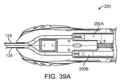
ホルダを通じて人工弁の位置決めを調節するために、ホルダは、好ましくは、搬送システムシャフトに剛的に取り付けられる。シャフトへのホルダとの接続は、好ましくは、軸線方向及び捩り力の両方に同時に抵抗する。ホルダ−シャフト接続の1つの例は、図25に描かれ、ここで、ホルダのアダプタ160のスナップ又は窪み168は、搬送システムのシャフト210の戻り止め212と協働する。アダプタ160及びシャフト210は、回転安定性のために自動位置合わせキー168を含むことができる。勿論、戻り止め、バヨネット、ネジ付き接続、玉軸受エアライン取り付け具、接続90°回転を必要とするシューホーン接続などを有する他のスナップ式のようないずれかの他の適切なホルダ−シャフト接続を使用することができる。そのような接続の一部の例は、2013年5月3日出願の「外科用心臓弁及び関連の装置、システム、及び方法」という名称の米国特許仮出願第61/819,488号明細書の図A9〜A12に示されており、上述のように、この特許出願は、それが本明細書に提示する開示に反しない範囲で引用によって本明細書に組み込まれている。
In order to adjust the positioning of the prosthetic valve through the holder, the holder is preferably rigidly attached to the transport system shaft. The connection with the holder to the shaft preferably resists both axial and torsional forces simultaneously. One example of a holder-shaft connection is depicted in FIG. 25, where the snap or recess 168 of the
追加の説明
以下で提供するのは、三脚ホルダ及びラチェット式搬送システム実施形態の追加の考察である。以下に提示する一部の実施形態は、上述したものと同じか又はこれらに類似している場合がある。
Additional Description Provided below are additional considerations of tripod holder and ratchet transport system embodiments. Some embodiments presented below may be the same as or similar to those described above.
この節に説明するホルダ及び搬送システムの実施形態は、取りわけ、無縫合弁搬送システムによる不正確な配置及び不十分な可視化に対する解決法を提供する。 The embodiment of the holder and delivery system described in this section provides a solution to inaccurate placement and inadequate visualization with a sutureless valve delivery system, among others.
好ましくは、人工弁は、ホルダと共にパッケージ化されると考えられる。外科医は、最初に自然弁環帯のサイズを決定し、次に、ホルダを有する適切な弁を選択する。次に、ホルダ/弁は、これらのパッケージから取り除かれて氷浴中に置かれことになる。次に、ホルダ/弁は、搬送システムシャフトに結合又は接続されることになる。次に、弁は、使い捨て可能なクリンパー又は内蔵型縫合糸のいずれかを使用してクリンピングすることができる。次に、圧縮弁は、交換すべき自然弁環帯のレベルまで患者の中に下げられることになり、温生理食塩水が、弁の上に噴霧されることになる。人工弁は回転し、従って、タブは自然リーフレット交連と位置合わせされ、ハンドル上のラチェットは、配備モードで作動することになる。人工弁拡張後に、位置決めが正しくなかった場合に、外科医は、ラチェットを圧縮モードに切り換えることになり、弁はクリンピングされて再位置決めされることになる。再位置決めを終了した後に、弁は、ここでもまた配備モードに徐々に出されることになり、位置決めを確認することになる。ホルダを人工弁から取り除くために、ボタンをハンドルで押し下げて縫合糸を切り離すことになる。ホルダを有するハンドルは、患者から取り除かれることになる。次に、3つの縫合残余物は、個々に人工弁から取り出して埋め込みを達成することになる。 Preferably, the prosthetic valve will be packaged with the holder. The surgeon first determines the size of the natural annulus and then selects the appropriate valve with the holder. The holder / valve will then be removed from these packages and placed in an ice bath. The holder / valve will then be coupled or connected to the transport system shaft. The valve can then be crimped using either a disposable crimper or a built-in suture. The compression valve will then be lowered into the patient to the level of the natural annulus to be replaced and warm saline will be sprayed over the valve. The prosthetic valve rotates, so the tabs are aligned with the natural leaflet commissure and the ratchet on the handle will operate in the deployed mode. If the positioning is not correct after the prosthetic valve dilation, the surgeon will switch the ratchet to compression mode and the valve will be crimped and repositioned. After finishing the repositioning, the valve will again be gradually put into the deployment mode, confirming the positioning. To remove the holder from the prosthetic valve, the button is pushed down with the handle and the suture is cut off. The handle with the holder will be removed from the patient. The three suture residues will then be individually removed from the prosthetic valve to achieve implantation.
不正確な配置は、3つの取外し可能な縫合糸によって弁に固定された三又のホルダを有することによって対処される。ホルダは、3つの位置でのその剛性取り付けにより自然弁環帯の人工弁の容易な回転及び再位置決めを可能にする。取付位置は、リーフレットの外側の上側流入カフ上及び/又はリーフレットの内側オリフィスを経る3つの突起を有する下側流入カフ上とすることができる。人工弁に固定された3つの縫合糸を使用して、ハンドルのラチェット機構によってこれらを強く引っ張ることにより弁直径を縮小することができる。人工弁は、弁を温め、縫合糸にかかる張力を解除する(逆徐々に動かす)ことによって配備することができる。上側及び下側流入の両方を制御したい場合に、追加の縫合糸は、ホルダの反対の流入の終わりまで囲まれることが可能である。120度で弁にクリンピングされる3つの縫合糸を有することにより、弁の均一な縮小が明らかにされている。ハンドルの切断機構を使用して縫合糸を切り離し、これらを配備後引き離すことを可能にすることができる。 Inaccurate placement is addressed by having a three-pronged holder secured to the valve by three removable sutures. The holder allows easy rotation and repositioning of the natural valve annulus artificial valve due to its rigid attachment in three positions. The attachment location can be on the upper inflow cuff on the outside of the leaflet and / or on the lower inflow cuff having three protrusions through the inner orifice of the leaflet. Using three sutures secured to the prosthetic valve, the valve diameter can be reduced by pulling them strongly by the handle ratchet mechanism. A prosthetic valve can be deployed by warming the valve and releasing the tension on the suture (reversely moving it). If it is desired to control both the upper and lower inflows, the additional suture can be enclosed to the end of the opposite inflow of the holder. Having three sutures crimped to the valve at 120 degrees reveals a uniform reduction of the valve. A handle cutting mechanism may be used to detach the sutures and allow them to be pulled apart after deployment.
この実施形態は、ちょうど3つの小さい管を使用して弁に取り付けるので、流入カフ及び生体構造の可視化は、あらゆるかさ高い円錐又は他の搬送ツール構成要素によって邪魔されない。人工弁を自然弁環帯上に着座させることの確認は、自然弁環帯が見られるまで人工弁の上側流入を簡単に徐々に動かすことによって達成することができる。 Since this embodiment attaches to the valve using just three small tubes, the visualization of the inflow cuff and anatomy is not disturbed by any bulky cone or other delivery tool component. Confirmation that the prosthetic valve is seated on the natural annulus can be achieved by simply gradually moving the upper inflow of the prosthetic valve until the natural annulus is seen.
ハンドル機構は、3つの縫合糸を直線的に後退させる歯車を作動させる単一プッシュボタンを有することができる。この線形移動を達成することで、歯車の周りのワイヤをスプール処理し、ウォーム歯車を使用して回転を線形移動に並進させ、又は簡単に連結を使用して望ましい線形移動を達成することによって達成することができる。プッシュボタンは、外科医の利き手にあることができ、又はテザーによってハンドルに取り付けることができ、次に、プッシュボタンは、外科医の利き手でない手又はアシスタントによって作動させることができる。純粋に機械的縫合糸締めつけ機構に代えて、サーボモータを使用して縫合糸を締めつけて緩めることができる。モータを使用することの利点は、ツールを作動させながらより大きい安定性を有することになることである(一方の手で容易に作動させることができる手持ち式ドリルに対して安定性のために2つの手を必要とする手回しドリルを使用することの性能の差に類似している)。いずれの場合にも、この実施形態は、弁圧縮機構が、2つの方向に圧縮及び配備モードで両方とも徐々に動かすことができることを仮定している。prawl又は滑車機構を使用して後向き運動を防止することができる。圧縮及び配備モードは、2つのラチェットボタンによるか又は圧縮/配備スイッチを有する1つのボタンによるかのいずれかで達成することができる。これに代えて、ネジ付きハンドルを使用することができる。 The handle mechanism can have a single push button that activates a gear that linearly retracts the three sutures. Achieving this linear movement is achieved by spooling the wire around the gear, translating the rotation to linear movement using a worm gear, or simply using linkage to achieve the desired linear movement can do. The push button can be in the surgeon's dominant hand or can be attached to the handle by a tether, and then the push button can be actuated by a non-dominant hand or assistant of the surgeon. Instead of a purely mechanical suture tightening mechanism, a servomotor can be used to tighten and loosen the suture. The advantage of using a motor is that it will have greater stability while operating the tool (2 for stability versus a hand-held drill that can be easily operated with one hand. Similar to the performance difference of using a hand drill that requires one hand). In either case, this embodiment assumes that the valve compression mechanism can be moved gradually in both compression and deployment modes in two directions. A prowl or pulley mechanism can be used to prevent backward movement. The compression and deployment mode can be achieved either by two ratchet buttons or by a single button with a compression / deployment switch. Alternatively, a threaded handle can be used.
以下に説明するのは、実施することができる配備段階である(サイジング後):(1)弁を濯ぎ、(2)弁を冷やし、(3)弁/ホルダを使い捨てクリンパーに移送し、(4)使い捨てクリンパーを有する弁にクリンピングし、(5)弁/ホルダを搬送ツールシャフトに取り付け、(6)クリンピングラチェットを作動させてホルダを締めつけ、(7)弁をクリンパーから取り外し、(8)円板をホルダから取り外し、(9)弁を環帯内に位置決めし、(10)弁を温め/食塩水を温め、(11)弁を適切な位置にラチェット解除し、(12)必要に応じてラチェットして再位置決めし/再配備し、(13)ホルダ取り外しボタンを作動させ、3つの収集縫合糸を切り離して可撓性後側シャフトをアンロックし、(14)可撓性後側シャフトを搬送ツールの背部から引っ張って収集縫合糸を取り外し、かつ(15)搬送ツール/ホルダを取り外す。 Described below are deployment steps that can be performed (after sizing): (1) Rinse the valve, (2) Cool the valve, (3) Transfer the valve / holder to a disposable crimper, (4 ) Crimp to a valve with a disposable crimper, (5) Attach the valve / holder to the transfer tool shaft, (6) Operate the crimping ratchet to tighten the holder, (7) Remove the valve from the crimper, (8) Circle Remove the plate from the holder, (9) position the valve within the annulus, (10) warm the valve / saline, (11) release the ratchet to the proper position, and (12) if necessary Ratcheting and repositioning / redeployment, (13) actuating the holder removal button, severing the three collection sutures and unlocking the flexible rear shaft, (14) flexible rear shaft Remove the collection suture pulled from the back of the transfer tool, and (15) remove the conveying tool / holder.
他の実施形態
多くの延長部を使用して流出レール又はタブに取り付ける1つと、プラスチックスリーブ又はバンドで流出レール及びタブを締める別のものとを含む三脚以外のホルダのバージョンを考えている。その例は、2013年5月3日出願の「外科用心臓弁及び関連の装置、システム、及び方法」という名称の米国特許仮出願第61/819,488号明細書の図A16〜A17に示されており、上述のように、この特許出願は、それが本明細書に提示する開示に反しない範囲で引用によって本明細書に組み込まれている。
Other Embodiments Consider a version of the holder other than a tripod that includes one that attaches to the outflow rail or tab using many extensions and another that tightens the outflow rail and tab with a plastic sleeve or band. Examples are shown in FIGS. A16-A17 of US Provisional Application No. 61 / 819,488, entitled “Surgical Heart Valve and Related Devices, Systems, and Methods,” filed May 3, 2013. As noted above, this patent application is incorporated herein by reference to the extent that it does not contradict the disclosure presented herein.
インプラント工程
例示目的のために、本明細書に説明するホルダ及び搬送システムの様々な実施形態を使用することができるMedtronic,Inc.のEnable II弁のような人工弁デバイスを埋め込むための手順にここに説明する。患者の自然リーフレットの除去及び自然環帯の創面切除の後に、外科医は、典型的には、自然環帯をサイズ決定し、適切な交換弁システムを選択する。次に、ホルダ及びコードを有する交換弁システムは、これらのパッケージから取り外されて氷浴中に置かれる。次に、ホルダ/弁は、典型的には、搬送システムシャフトに結合又は接続される。次に、人工弁は、使い捨てクリンパー又は内蔵型縫合糸のいずれかを使用してクリンピングされることになる。これに代えて、人工弁は、搬送システムに取り付ける前にクリンピングすることができる。クリンピングされた人工弁は、患者内に位置決めされて自然弁環帯のレベルまで下げることになり、温生理食塩水は、人工弁の上に噴霧されることになる。人工弁の上側流入は、張力を受けて周方向ループによりクリンピングされたままになる。人工弁は回転することになるので、タブは自然リーフレット交連と位置合わせされ、搬送システム作動要素を作動させてループにかかる張力を解除することになる。次に、外科医は、搬送システム及びホルダを外科用空洞から摺動して落として人工弁の位置決めを点検することになる。位置決めが正しくなかった場合に、外科医は、搬送システムを摺動させて人工弁に戻し、搬送システム上の作動要素を作動させ、人工弁は、張力を受けたループを通じてクリンピングされることになり、再位置決めすることができる。再位置決めが終了した後に、人工弁は、配備システムを通じてここでもまた配備されることになり、位置決めを確認することになる。人工弁配備工程を終了するために、コードは、搬送システムが外科用空洞から引っ張り出される時に切断されることになる。次に、縫合残余物は、個々に人工弁から取り出されて埋め込みを達成することになる。
For exemplary purposes of the implant process , various embodiments of the holder and delivery system described herein may be used by Medtronic, Inc. A procedure for implanting a prosthetic valve device, such as the Enable II valve, is described herein. After removal of the patient's natural leaflet and debridement of the natural annulus, the surgeon typically sizes the natural annulus and selects an appropriate replacement valve system. The exchange valve system with holder and cord is then removed from these packages and placed in an ice bath. The holder / valve is then typically coupled or connected to the transport system shaft. The prosthetic valve will then be crimped using either a disposable crimper or a built-in suture. Alternatively, the prosthetic valve can be crimped before being attached to the delivery system. The crimped prosthetic valve will be positioned within the patient and lowered to the level of the natural annulus and warm saline will be sprayed over the prosthetic valve. The upper inflow of the prosthetic valve remains tensioned by the circumferential loop under tension. As the prosthetic valve will rotate, the tab will be aligned with the natural leaflet commissure and actuate the transport system actuating element to release the tension on the loop. The surgeon will then slide the delivery system and holder out of the surgical cavity to check the positioning of the prosthetic valve. If the positioning is not correct, the surgeon will slide the delivery system back into the prosthetic valve and actuate the actuating element on the delivery system, which will be crimped through the tensioned loop, It can be repositioned. After repositioning is complete, the prosthetic valve will again be deployed through the deployment system to confirm positioning. To complete the prosthetic valve deployment process, the cord will be cut when the delivery system is pulled out of the surgical cavity. The suture residue is then individually removed from the prosthetic valve to achieve implantation.
人工弁の初期配備が自然弁環帯の上方である場合に、人工弁フレームの上側流入部分の周りのループの再張力付与は、上側流入を単に低減することになり、従って、拡張下側流入カフが自然弁環帯の下を通ることを可能にしない。従って、1つ又はそれよりも多くのループは、流入カフの下側部分の周りに位置決めすることができ、又は人工弁は、外科用空洞から取り外されて再クリンピングすることができる。人工弁を再クリンピングするために、フレーム又はその構成要素が例えば、「ニチノール」のような形状記憶材料から形成される場合に、最初に、人工弁を温めてそれをその本来の形状に戻すことができる。次に、人工弁を冷やすことができ、クラムシェル漏斗のような漏斗は、人工弁の近位の搬送システムシャフト上に置くことができる。ガイドを使用して、漏斗を通じて人工弁を案内し、人工弁全体にクリンピングすることができる。クラムシェル漏斗を開放することができ、人工弁は、人工弁ガイドから取り外すことができ、かつ作動要素を作動させることによってあらゆる残留コード緩みを集めることができる。 When the initial deployment of the prosthetic valve is above the natural annulus, re-tensioning of the loop around the upper inflow portion of the prosthetic valve frame will simply reduce the upper inflow, and thus the expanded lower inflow Does not allow the cuff to pass under the natural annulus. Thus, one or more loops can be positioned around the lower portion of the inflow cuff, or the prosthetic valve can be removed from the surgical cavity and re-crimped. To re-crimp the prosthetic valve, if the frame or its components are formed from a shape memory material such as “Nitinol”, first warm the prosthetic valve back to its original shape Can do. The prosthetic valve can then be cooled and a funnel, such as a clamshell funnel, can be placed on the delivery system shaft proximal to the prosthetic valve. The guide can be used to guide the prosthetic valve through a funnel and crimp the entire prosthetic valve. The clamshell funnel can be opened, the prosthetic valve can be removed from the prosthetic valve guide, and any residual cord slack can be collected by actuating the actuating element.
搬送システムテザー係合方法
一部の実施形態において、搬送システムは、少なくとも3つの機能を実施する。第1に、ホルダのアダプタ及びコードと接続することができる。第2に、軸線方向にコードを張力付与することによって人工弁の上側流入カフのような人工弁の少なくとも一部分をクリンピングすることができる。第3に、人工弁の部分が拡張すること及びホルダが摺動して弁から戻ることを可能にするコードにかかる張力を全て又は実質的に全て解除することができる。
Transport System Tether Engagement Method In some embodiments, the transport system performs at least three functions. First, it can be connected to the adapter and cord of the holder. Second, at least a portion of the prosthetic valve, such as the upper inflow cuff of the prosthetic valve, can be crimped by tensioning the cord in the axial direction. Third, all or substantially all of the tension on the cord that allows the portion of the prosthetic valve to expand and the holder to slide back from the valve can be released.
コードは、あらゆる適切な方式で搬送ツール張力付与機構に接続することができ、搬送ツールは、あらゆる適切な張力付与機構を有することができる。接続及び張力付与機構の例は、ワイヤを含むコードであり、コードは、コイリングホイールに巻き付けることができる。コイリングホイールは、ツールの中心平面と平行に又はツールの中心線といずれかの他の向きで位置決めすることができる。コイリングホイールは、初期設定のためにホイールに結合する金属テザーの容易な接続を考慮するその中に磁石を有することができる。別の実施形態において、コードは、コイリングホイールの孔を通じて直接引っ張ることができ、ホイールの数回転後に、コードはホイールに剛的に取り付けられる。 The cord can be connected to the transport tool tensioning mechanism in any suitable manner, and the transport tool can have any suitable tensioning mechanism. An example of a connection and tensioning mechanism is a cord that includes a wire, which can be wrapped around a coiling wheel. The coiling wheel can be positioned parallel to the center plane of the tool or in any other orientation with respect to the center line of the tool. The coiling wheel can have a magnet in it that allows for easy connection of a metal tether that couples to the wheel for initialization. In another embodiment, the cord can be pulled directly through the hole in the coiling wheel, and after several revolutions of the wheel, the cord is rigidly attached to the wheel.
張力付与機構としてコイリングホイールを含む搬送ツール200の実施形態は、図26〜27に示されている。図26に示すように、搬送ツール200は、ホルダ160のアダプタに接続されたシャフト210を有する。1つ又はそれよりも多くのコード(図26には示さず)は、シャフト210の1つ又はそれよりも多くの導管を通って延び、ハンドル220に収容された張力付与機構に接続する。ハンドルは、作動機構230A、230B、この場合はクランク230A及び張力解除ボタン230Bを含む。クランク230Aを回転させて、コードにかかる張力を増減させることができる。張力解除ボタン230Bを押し下げて、コードにかかる張力を全て又は実質的に全て解除することができる。
An embodiment of a
図27は、図26に示す搬送ツール200の張力付与機構の実施形態を示している。図示のように、シャフト210は、コード125に対して導管を形成する内腔215を有し、コード125は、張力付与ホイール410に結合される。張力付与ホイール410は、シャフト412の回りで回転してコード125にかかる張力を調節することができる。
FIG. 27 shows an embodiment of a tension applying mechanism of the
搬送ツールが張力付与機構及び解除機構(例えば、図26に示す実施形態)を有する搬送ツール及びホルダと共に人工弁を埋め込むために使用することができる1つの方法の例は、(1)搬送ツール張力付与機構に対してコードを捕捉して引っ張り、(2)張力付与機構にコードを接続し、(3)張力付与機構を作動させて人工弁を収縮又はクリンピングし、(4)必要又は望ましい場合圧縮デバイスで人工弁にクリンピングし、(5)患者の外科用空洞内に人工弁を位置決めし、(6)弁を温め、(7)張力付与機構の解除ボタンを押圧して人工弁の拡張を可能にし、(8)必要に応じて、張力付与機構を作動させて人工弁を再び締め/再位置決めし、(9)張力付与機構の解除ボタンを保持しながら、患者の外科用空洞からツール/ホルダを引っ張り出し、(10)人工弁の正しい埋め込み位置を確認し、(11)コードを切断して人工弁の周りから取り外すことを含む。 An example of one method that the transport tool can be used to embed the prosthetic valve with a transport tool and holder having a tensioning mechanism and a release mechanism (eg, the embodiment shown in FIG. 26) is: (1) Transport tool tension Capture and pull the cord against the application mechanism, (2) connect the cord to the tension application mechanism, (3) operate the tension application mechanism to contract or crimp the prosthetic valve, and (4) compress if necessary or desired The device can be crimped to the prosthetic valve, (5) positioning the prosthetic valve in the patient's surgical cavity, (6) warming the valve, and (7) pressing the release button on the tensioning mechanism to expand the prosthetic valve And (8) actuate the tensioning mechanism to re-tighten / reposition the prosthetic valve, if necessary, and (9) hold the release button on the tensioning mechanism while holding the tool / hold from the patient's surgical cavity. The pulled, to determine the correct embedding position of (10) prosthetic valves, including removing from around the prosthetic valve by cutting (11) code.
一部の実施形態において、コードは、ラック、ビーズチェーン、ベルト及び/又は3D滑車を含み、張力付与機構は、コードと係合する平歯車スプロケット、スクリュー、及び/又はウォーム歯車を含む。例えば、図28は、ビーズチェーンを有するコード125及びビーズチェーンと係合するように構成されたスプロケット510を含む。スプロケット510の回転は、コード125にかかる張力を増減させることができる。
In some embodiments, the cord includes a rack, bead chain, belt, and / or 3D pulley, and the tensioning mechanism includes a spur gear sprocket, screw, and / or worm gear that engages the cord. For example, FIG. 28 includes a
最少構成要素によってベルトを進める1つの方法は、インデックス結合機構を使用することになる。近位方向に進む時に把持し、遠位方向に進む時に緩む結合穴あき構成要素を使用することができる。これは、ベルトと直角の角度を非把持方向に及び把持方向に僅かな角度で変えることによって達成することができる。 One way to advance the belt with minimal components would be to use an index coupling mechanism. A coupling perforated component can be used that grips when going in the proximal direction and loosens when going in the distal direction. This can be achieved by changing the angle perpendicular to the belt in the non-gripping direction and a slight angle in the gripping direction.
簡単なベルト又は可撓性ラックを使用することに加えて又はこれに代えて、粗面を有するベルト又はチェーンベルトのような特定な形状を使用することができる。 In addition to or instead of using simple belts or flexible racks, specific shapes such as belts with rough surfaces or chain belts can be used.
コードを張力機構に結合するための及び張力機構を制御するための機構の例は、2013年5月3日出願の「外科用心臓弁及び関連の装置、システム、及び方法」という名称の米国特許仮出願第61/819,488号明細書の図19〜A40に描かれてこれに関して考察されており、上述のように、この特許出願は、それが本明細書に提示する開示に反しない範囲で引用によって本明細書に組み込まれている。 An example of a mechanism for coupling a cord to a tensioning mechanism and for controlling the tensioning mechanism is a U.S. patent entitled "Surgical Heart Valve and Related Devices, Systems, and Methods" filed May 3, 2013. 19-A40 of provisional application 61 / 819,488, discussed in this regard, and as mentioned above, this patent application is within the scope that it does not contradict the disclosure presented herein. Are incorporated herein by reference.
テザーアダプタは、コードの一部をコードが張力付与機構と嵌合することができるように形成することができる。コード(例えば、縫合糸)の遠位部分は、アダプタの中に入れることができる。勿論、結び、接着剤、又はクリンピングなどのいかなるいずれかの他の適切な機構を使用して、コードの遠位部分を張力付与機構と嵌合するように構成されたアダプタと結合させることができる。アダプタは、あらゆる適切な特徴を有し、ラック、ビーズチェーン、ベルト、3D滑車、及び/ないかなる張力付与機構と嵌合することができる。コードを単独で制御することになる場合に、そのようなコードは、与えられたテザーアダプタに互いに結合することができる。 The tether adapter can be formed such that a portion of the cord can be engaged with the tensioning mechanism. The distal portion of the cord (eg, suture) can be placed into the adapter. Of course, any other suitable mechanism such as knots, adhesives, or crimping can be used to couple the distal portion of the cord with an adapter configured to mate with a tensioning mechanism. . The adapter has any suitable feature and can mate with a rack, bead chain, belt, 3D pulley, and / or any tensioning mechanism. Such codes can be coupled together to a given tether adapter if the code is to be controlled alone.
スプロケット張力機構を有する搬送ツールの例は、図29に示されている。図示の実施形態において、スプロケット510は、コード125のビーズチェーンと係合する。スプロケット510は、歯車520と係合する平歯車530に結合される。作動要素230(この場合に、回転可能なつまみ)の回転運動は、歯車520を回転させ、歯車520は、平歯車430及びスプロケット510を回転させ、それによってコード125にかかる張力を調節する。
An example of a transport tool having a sprocket tension mechanism is shown in FIG. In the illustrated embodiment, the
1つ又はそれよりも多くの作動要素は、搬送デバイスのハンドルのあらゆる適切な位置に置くことができる。図26に示すように、作動要素は、ハンドルの側部(例えば、上部、底部、又は側部)上に置くことができる。図29に示すように、作動要素は、ハンドルの背部に置くことができる。一部の実施形態において、作動機構は、モータ及び好ましい制御電子装置に結合されたボタン、スイッチ、つまみ、及び/又はレバーなどである。従って、テザリング機構は、機構を手動で作動させる(例えば、徐々に動かす、回転する、クランクを回転させる、その他)のではなくモータによって給電することができる。 One or more actuating elements can be placed in any suitable position on the handle of the transport device. As shown in FIG. 26, the actuating element can be placed on the side (eg, top, bottom, or side) of the handle. As shown in FIG. 29, the actuating element can be placed on the back of the handle. In some embodiments, the actuation mechanism is a button, switch, knob, and / or lever, etc. coupled to the motor and preferred control electronics. Thus, the tethering mechanism can be powered by the motor rather than manually operating the mechanism (eg, gradually moving, rotating, rotating the crank, etc.).
電気機械的搬送システムで達成されるテザー張力付与機能の例は、図30に示されている。搬送ツールのハンドルのハウジングには、例えば、回路基板及びハンドル上に配置された作動要素230、270に対する適切な接続のようなスプールラックインタフェース、電源630、制御電子装置620を備えた線形サーボモータ又は回転モータのようなモータ610が配置される。電源630、制御電子装置620、及びモータ610は、作動可能に結合される。作動要素230、270を作動させて、コードにかかる張力を制御することができる。一例として、作動要素230の前側部分232を押し下げて、張力を増加させることができ、要素230の後側部分234を押し下げて張力を増加させることができる。張力解除ボタン700も含むことができる。
An example of a tether tensioning function achieved with an electromechanical transport system is shown in FIG. The housing of the handle of the transfer tool may include a linear servo motor with a spool rack interface, such as a circuit board and suitable connections to actuating
動力搬送システムに使用することができる他の機構又は作動要素は、2013年5月3日出願の「外科用心臓弁及び関連の装置、システム、及び方法」という名称の米国特許仮出願第61/819,488号明細書の図A42〜A47に示されており、上述のように、この特許出願は、それが本明細書に提示する開示に反しない範囲で引用によって本明細書に組み込まれている。 Other mechanisms or actuating elements that can be used in the power delivery system are described in US Provisional Patent Application No. 61/61, entitled “Surgical Heart Valves and Related Devices, Systems, and Methods” filed May 3, 2013 As shown above, this patent application is incorporated herein by reference to the extent it does not contradict the disclosure presented herein. Yes.
張力を制御する遠隔ユニット
一部の実施形態において、1つ又はそれよりも多くのコードにかかる張力を制御するための1つ又はそれよりも多くの作動要素は、搬送ツールのハンドルから離れて位置決めすることができる。そのような実施形態は、一方の手の使用が人工弁を位置付けることを可能にし、別の手の使用が1つ又はそれよりも多くのコードにかかる張力を通じて収縮又は拡張を制御することを可能にし、又は2人の人が異なる態様を実施することを可能にする。
Remote unit controlling tension In some embodiments, one or more actuating elements for controlling tension on one or more cords are positioned away from the handle of the transport tool. can do. Such an embodiment allows the use of one hand to position the prosthetic valve and allows the use of another hand to control contraction or expansion through tension on one or more cords. Or allows two people to implement different aspects.
張力機構が動力を供給される時に、張力付与機構は、ハンドルに配置することができ、作動機構は、ハンドルの張力付与機構に電気的に又は遠隔に結合されたハンドルから距離を置くことができる。 When the tensioning mechanism is powered, the tensioning mechanism can be located on the handle and the actuation mechanism can be spaced from a handle that is electrically or remotely coupled to the tensioning mechanism of the handle. .
搬送ツールのハンドルから離れて作動要素を有する搬送システムの例は、図31〜32に示されている。図31に示す実施形態において、ハンドル220は作動要素230を含み、遠隔ユニット260は、可撓性シャフト250を通じてハンドル220の結合された別の作動要素240を含む。これは、1人のユーザ(又は2人のユーザ)が一方の手(又は一方のユーザ)を使用してハンドル220及び作動要素230を通じて人工弁を位置決めし、別の手(又は別のユーザ)が遠隔ユニット上の作動要素240を作動させる。作動要素230、240を使用して、同じか又は異なるコードの張力を制御することができる。同じコードを制御するのに使用する場合に、ユーザは、いずれの手(いずれのユーザ)を使用するかを選択することができる。一部の実施形態において、作動要素230は、張力解除作動要素であり、作動要素240は張力制御要素である。
An example of a transport system having an actuating element away from the handle of the transport tool is shown in FIGS. In the embodiment shown in FIG. 31, the
図32に示す実施形態において、ハンドル220は、作動要素を含まないが、可撓性シャフト250を通じてハンドル220に結合された遠隔ユニット260は、1つ又はそれよりも多くの作動要素(230の1つだけが示された)を含む。
In the embodiment shown in FIG. 32, the
他の実施形態は、2013年5月3日出願の「外科用心臓弁及び関連の装置、システム、及び方法」という名称の米国特許仮出願第61/819,488号明細書の図A42〜A43に示してこれに関して考察されており、上述のように、この特許出願は、それが本明細書に提示する開示に反しない範囲で引用によって本明細書に組み込まれている。 Another embodiment is disclosed in Figures A42-A43 of US Provisional Application No. 61 / 819,488, entitled “Surgical Heart Valve and Related Devices, Systems, and Methods,” filed May 3, 2013. And as discussed above, this patent application is incorporated herein by reference to the extent that it does not contradict the disclosure presented herein.
調節可能なシャフトの概念
一部の外科医は、あらゆる与えられた患者に応じてハンドルのシャフト長さに関して異なる好みを有する場合がある。従って、本明細書に説明する搬送ツールのシャフトは、あらゆる適切な長さを有することができ又は調節可能にすることができる。例えば、ロック/アンロックスイッチを使用する調節可能な長さのシャフトの実施形態は、2013年5月3日出願の「外科用心臓弁及び関連の装置、システム、及び方法」という名称の米国特許仮出願第61/819,488号明細書の図A51に示してこれに関して考察されており、上述のように、この特許出願は、それが本明細書に提示する開示に反しない範囲で引用によって本明細書に組み込まれている。
Adjustable shaft concept Some surgeons may have different preferences regarding the shaft length of the handle depending on any given patient. Thus, the shaft of the transfer tool described herein can have any suitable length or can be adjustable. For example, an adjustable length shaft embodiment using a lock / unlock switch is disclosed in a US patent entitled “Surgical Heart Valves and Related Devices, Systems, and Methods” filed May 3, 2013. Provisional application 61 / 819,488, shown in Figure A51 and discussed in this regard, and as noted above, this patent application is incorporated by reference to the extent that it does not contradict the disclosure presented herein. Is incorporated herein.
コード切断機構
人工弁を適正に埋込んだ後にコードを切断する1つの方法は、ユーザにハサミを取らせてコードを切断することである。別の方法は、コードを自動的に切断させることである。これは、搬送システムハンドルで、シャフトで、ホルダ内で、その他で行うことができる。本明細書で考えているアイデアの一部は、鋭いディスクの回転、鋭い刃先の軸線方向移動を含み、又は多くの外科用弁に対して行われるようにホルダ上に隆起切断点を有することである。1つのバージョンでは、コードの一端(2つのアームがホルダ、シャフト又は搬送システムを通じて与えられる実施形態において)は、ホルダシャフト、又は搬送システム、その他に固定されたままになり、コードを搬送システムハンドルで引っ張り出すことを可能にする。第2の企図は、搬送システムが取り外された後に弁の回りにコードを残すことになり、コードの各々を個々に引っ張り出すことを可能にする。第3の企図は、コードの各々に搬送システムによって区分的に弁から自動的に引っ張らせることになる。
One method of cutting the cord after properly embedding the cord cutting mechanism prosthetic valve is to let the user take scissors and cut the cord. Another method is to automatically cut the cord. This can be done with the transport system handle, with the shaft, in the holder, and others. Some of the ideas considered here include rotating the sharp disc, axial movement of the sharp cutting edge, or having raised cut points on the holder as is done for many surgical valves. is there. In one version, one end of the cord (in embodiments where two arms are provided through a holder, shaft or transport system) remains fixed to the holder shaft or transport system, etc., and the cord is attached to the transport system handle. Allows to pull out. A second attempt would leave cords around the valve after the transport system was removed, allowing each of the cords to be pulled out individually. A third attempt would be to cause each of the cords to be automatically pulled from the valve piecewise by the transport system.
搬送ツールの中に組み込まれた切断装置の例は、2013年5月3日出願の「外科用心臓弁及び関連の装置、システム、及び方法」という名称の米国特許仮出願第61/819,488号明細書の図A13〜A14及びA48〜A50に示されており、上述のように、この特許出願は、それが本明細書に提示する開示に反しない範囲で引用によって本明細書に組み込まれている。手動切断のための隆起切断点及びコードの例は、米国特許仮出願第61/819,488号明細書の図A15に示されている。 An example of a cutting device incorporated into a delivery tool is US Provisional Application No. 61 / 819,488, entitled “Surgical Heart Valve and Related Devices, Systems, and Methods,” filed May 3, 2013. As noted above, this patent application is incorporated herein by reference to the extent that it does not contradict the disclosure presented herein. ing. Examples of raised cut points and cords for manual cutting are shown in FIG. A15 of US Provisional Application No. 61 / 819,488.
一部の実施形態において、コードはハンドル内で切り離され、ハンドルはシャフトから切断可能である。コード切断要素を作動させた後に、ハンドルはシャフトから切断される。シャフトは、ホルダが適切な位置に(例えば、上側流入カフのレベルで)残るように保持することができ、縫合糸は、1つずつ引っ張り出すことができる。縫合糸は、非垂直に人工弁から半径方向に引っ張られるので(所定位置でホルダにより)、弁から縫合糸を引っ張る弁脱落の危険がほとんどないか又は全くない。 In some embodiments, the cord is disconnected within the handle, and the handle can be cut from the shaft. After actuating the cord cutting element, the handle is cut from the shaft. The shaft can be held so that the holder remains in place (eg, at the level of the upper inflow cuff) and the sutures can be pulled out one by one. Since the suture is pulled radially from the prosthetic valve non-vertically (with a holder in place), there is little or no risk of valve dropout pulling the suture from the valve.
一部の実施形態において、搬送ツールハンドルが後退する時に自動コード取り外しが行われる。そのような実施形態において、人工弁に対して適切な位置にホルダを維持することが望ましい。ホルダはループ(例えば、弁流入カフ)のレベルにあるので、力は全て半径方向であり、この工程から弁脱落の危険はほとんどないか又は全くない。 In some embodiments, automatic cord removal occurs when the transport tool handle is retracted. In such embodiments, it is desirable to maintain the holder in a proper position relative to the prosthetic valve. Since the holder is at the level of the loop (eg, the valve inflow cuff), all forces are radial and there is little or no risk of valve dropout from this process.
オフセットホルダを有する実施形態
この節で提供する考察は、一般的に、人工弁の縦軸線から延長部がオフセットされたホルダに関する。しかし、この節で提示する考察の一部は、本明細書に説明するあらゆるホルダ又は搬送システムに適用することができることは理解されるであろう(例えば、クリンプ制限器、迅速接続、ハンドル及び作動要素構成、埋め込み手順、その他に関する以下の考察)。
Embodiments with Offset Holders The considerations provided in this section generally relate to holders whose extensions are offset from the longitudinal axis of the prosthetic valve. However, it will be understood that some of the considerations presented in this section can be applied to any holder or transport system described herein (eg, crimp limiters, quick connect, handles and actuating elements). The following considerations regarding configuration, embedding procedure, etc.).
一部の実施形態において、搬送デバイスのホルダ及びシャフトは、人工弁の縦軸線からオフセットされ、埋め込み中の医師の視野を改善する。1つのそのような実施形態は、図33に示されている。図示のように、ホルダ100は、2つの延長部110、150(しかし、多くはあらゆる適切な数の延長部を含む)及びアダプタ160を含み、延長部の相対位置を保持してコードを管理する(例えば、図1〜9で上述のように)。アダプタ160は、シャフト及びホルダがオフセットされて人工弁20の縦軸線にほぼ平行になるように搬送ツールのシャフト210に接続するように構成される。示された実施形態において、延長部110は、弁20の外部に延びるが(すなわち、自己拡張式フレーム24の中心開口部内ではない)、延長部150は、自己拡張式フレーム24の中心開口部内に延びる。
In some embodiments, the holder and shaft of the delivery device are offset from the longitudinal axis of the prosthetic valve to improve the view of the implanting physician. One such embodiment is shown in FIG. As shown, the
図33に示す実施形態において、人工弁は、スカートの上部にある上側流入領域4、スカートの底部にある下側流入領域6、及びスカート腰部5、並びに上側流出領域1、中間流出領域2、及び下側流出領域3を有する。この節においてホルダ又は搬送デバイスを考察する時に、図33に示すような人工弁を多くの場合に説明する。しかし、この節に説明するホルダ及び搬送システムを使用して、他の構成を有する人工弁を搬送することができることは理解されるであろう。
In the embodiment shown in FIG. 33, the prosthetic valve comprises an
さらに、図33を参照すると、ホルダ100は、ループ120、130、140を有し、1つのループは、人工弁20の上側流入領域4の回りに配置され、別のループは、下側流入領域6の回りに配置され、他のループは、中間流入領域2から上側流入領域1の回りに配置される。
Further, referring to FIG. 33, the
図33に示すように、弁装置は、上縁、下縁、及び腰部を有するスカートを含むことができる。スカートは、マーキング7を含み、患者の環帯との位置合わせ及び交連と位置合わせをするための1つ又はそれよりも多くのマーキング8、又は両マーキング7、8を容易にすることができる。マーキングに関する追加の情報は、2013年5月3日出願の「外科用心臓弁及び関連の装置、システム、及び方法」という名称の米国特許仮出願第61/819,488号明細書、2014年1月23日出願の「外科用心臓弁及び関連の装置、システム、及び方法」という名称の米国特許仮出願第61/930,851号明細書、及び本米国特許非仮出願と同日出願の代理人整理番号C00007020.USU2を有する「弁に埋め込むための医療デバイス及び関連の方法」という名称の米国特許出願第14,268,925号明細書に説明されており、これらの特許出願は、これらが本発明の開示に反しない範囲で引用によって本明細書に組み込まれている。 As shown in FIG. 33, the valve device can include a skirt having an upper edge, a lower edge, and a waist. The skirt can include markings 7 to facilitate one or more markings 8 or both markings 7, 8 for alignment with the patient's annulus and alignment with commissures. Additional information regarding markings can be found in US Provisional Application No. 61 / 819,488, filed May 3, 2013, entitled “Surgical Heart Valves and Related Devices, Systems, and Methods,” 2014/1. US Provisional Patent Application No. 61 / 930,851, entitled “Surgical Heart Valve and Related Devices, Systems, and Methods,” filed on Jan. 23, and the same application as this non-provisional application. Reference number C000000070. U.S. Patent Application No. 14,268,925 entitled "Medical Devices for Implantation in Valves and Related Methods" with USU2, these patent applications are hereby incorporated by reference into the present disclosure. To the extent not contrary, it is incorporated herein by reference.
ここで図34Aを参照すると、図33に示すホルダの実施形態の概略図が、取り込まれた人工弁デバイス20なしに示されている。一方の延長部110の開口部112からループ130が出ている。他方の延長部150の第1の開口部154からループ110が出て、延長部150の別の開口部152から別のループ140が出ている。ループ120、130、140を形成するコードの一部分は、延長部110、150の導管を通じて及びアダプタ160を通って延びる。延長部及びアダプタは、あらゆる適切な数の導管を有することができる。
Referring now to FIG. 34A, a schematic diagram of the embodiment of the holder shown in FIG. 33 is shown without the incorporated
ここで図34Bを参照すると、図34Aに示すホルダの縦方向断面の実施形態が示されている。図示の実施形態において、第1の延長部110は、延長部の長さ延びる導管115を有し、第2の延長部150は、延長部の長さ延びる導管155を有し、アダプタ160は、アダプタの長さのビル導管165を有する。アダプタの導管165は、第1の延長部の導管115及び第2の延長部の導管155と連通している。ループ(図34Bには描かず)を形成するコード125の一部分は、第1の延長部の導管115及びアダプタの導管165を通って延び、ループ(図34Bには描かず)を形成するコード125、145の部分は、第2の延長部の導管155及びアダプタの導管165を通って延びる。1つの導管は第1の延長部、第2の延長部、及びアダプタの各々に対して示されているが、ホルダ及びその構成要素は、コードを管理するためにあらゆる適切な数の導管を有することができることは理解されるであろう。アダプタ(及び搬送システムシャフト)を超えて延びるコードの端部部分は、張力装置(例えば、上述のような)を制御するために1つ又はそれよりも多くの張力装置及び作動要素と作動可能に結合することができる。ループは、個々に又は2つ又はそれよりも多くの群として制御することができる。
Referring now to FIG. 34B, there is shown an embodiment of the longitudinal section of the holder shown in FIG. 34A. In the illustrated embodiment, the
図34A〜Bに示すホルダは2つの延長部を含むが、好ましいホルダは、いずれかの他の適切な数の延長部を含むことができることは理解されるであろう。例えば、3つのループを使用する場合に、ホルダは、1つ、2つ、又は3つの延長部を合理的に有することができる。 Although the holder shown in FIGS. 34A-B includes two extensions, it will be understood that a preferred holder can include any other suitable number of extensions. For example, if three loops are used, the holder can reasonably have one, two, or three extensions.
ホルダ、ループ、又はハンドルは、いずれか1つ又はそれよりも多くのループを収縮して弁装置のクリンピングを制限することができる量を限定又は制限し、それによって弁が過度にクリンピングされるのを防止することができる。あらゆる適切なクリンプ制限器を使用することができる。実施形態において、クリンプ制限は、ビーズをループ線に組み立て、圧縮スリーブをビーズの背後で組み立てることによって達成することができ、次に、これは、ループが移動することができる移動量を制限する。制限器は、いずれか1つ又はそれよりも多くのループ線上に置くことができる。好ましくは、制限器は、上側スカート/下側流出領域のような流出領域において弁装置を保持するように構成されたループ上に置かれる。 The holder, loop, or handle limits or limits the amount by which any one or more loops can be contracted to limit the crimping of the valve device, thereby over-crimping the valve. Can be prevented. Any suitable crimp limiter can be used. In embodiments, crimp restriction can be achieved by assembling the beads into the loop line and assembling the compression sleeve behind the beads, which in turn limits the amount of movement that the loop can move. The limiter can be placed on any one or more loop lines. Preferably, the restrictor is placed on a loop configured to hold the valve device in an outflow region such as the upper skirt / lower outflow region.
一部の実施形態において、2つ又はそれよりも多くのループは、同じ機構によって作動させることができる。そのような実施形態において、ループのうちの1つに対する戻り止めは、同じ機構によって制御されるループの全てのクリンピングを実質的に制限することができる。 In some embodiments, two or more loops can be actuated by the same mechanism. In such embodiments, a detent for one of the loops can substantially limit all crimping of the loops controlled by the same mechanism.
一部の実施形態において、クリンプ制限器は、下側流入領域にあるループに対しては使用されない。下側流入領域は、弁又はフレームの損傷に関する懸念をあまり呈示しない。勿論、クリンプ制限器は、この領域においてループに使用することができる。 In some embodiments, crimp limiters are not used for loops in the lower inflow region. The lower inflow region presents less concern regarding valve or frame damage. Of course, a crimp limiter can be used for the loop in this region.
クリンプ制限器(例えば、上述の戻り止め)は、好ましくは、一貫した方式で製造することができる。上述の実施形態に対して、戻り止めは、正確な糸結び及びループ線長さに依存してクリンプ停止位置で低可変性を得る。低可変性組み立て工程を容易にするために、製造治具を有効設計に使用することができる。実施形態において、治具は、所定位置に弁装置を保持するポスト及び結び目/圧縮スリーブが属する縫合糸長さを設定するポストを伴う場合がある。圧縮スリーブを使用することにより、戻り止めを再生可能に置くことができる。圧縮スリーブ単独では、弁の緊締で見られる力に対して十分に強力ではない場合があるので、結び目は、戻り止めの滑りを防止する圧縮スリーブのすぐ背後又は前面に置くことができる。 Crimp limiters (eg, detents described above) can preferably be manufactured in a consistent manner. For the above-described embodiment, the detent obtains low variability at the crimp stop position depending on the exact yarn knot and loop line length. In order to facilitate the low variability assembly process, manufacturing jigs can be used for effective design. In embodiments, the jig may involve a post that holds the valve device in place and a post that sets the suture length to which the knot / compression sleeve belongs. By using a compression sleeve, the detent can be placed reproducibly. Since the compression sleeve alone may not be strong enough against the force seen with valve tightening, the knot can be placed directly behind or in front of the compression sleeve to prevent detent slip.
ホルダを弁装置と作動可能に結合するための製造工程の実施形態の概観は、3つのレベルで弁装置のフレームの交連に対して組み立てループを含む。次に、ビーズは、上側スカート領域に弁装置を保持するように構成されたループの1つのアームに組み立てられる。次に、ホルダは、3つの確実なループの上に組み立てられる。次に、圧縮スリーブ又は迅速接続構成要素を追加して、過度のループ材料長さを切り取る。 An overview of an embodiment of a manufacturing process for operably coupling a holder with a valve device includes assembly loops for commissure of the valve device frame at three levels. The beads are then assembled into one arm of a loop configured to hold the valve device in the upper skirt region. The holder is then assembled on three positive loops. Next, a compression sleeve or quick connect component is added to cut off excess loop material length.
実施形態において、1つ又はそれよりも多くのループは、弁装置に(例えば、フレームに)結合され、ループが弁装置から滑り落ちるのを防止する。実施形態において、ループは、交連を通じて結合される。実施形態において、ループは縫合糸を通じて結合される。勿論、ループは、あらゆる適切な位置に及びあらゆる適切な方式で結合することができる。例えば、フレームは、ループを制約する巻き毛のピッグテールを有することができ、フレームは、外向きに広がって縫合糸が摺動して落ちることなどを防止することができる。 In embodiments, one or more loops are coupled to the valve device (eg, to the frame) to prevent the loop from sliding off the valve device. In embodiments, the loops are joined through commissures. In embodiments, the loops are joined through sutures. Of course, the loops can be coupled to any suitable location and in any suitable manner. For example, the frame can have curly pigtails that constrain the loop, and the frame can spread outward to prevent the suture from sliding and falling.
ここで図35を参照すると、円板状クリンプ制限要素196、198を有するホルダ100の実施形態が示されている。ホルダ100は、1つの延長部110又は脚が人工弁20の外側にあり、1つの延長部150が弁20の中心開口部内に位置決めされるように位置決めされる。円板クリンプ制限器196、198は、人工弁20内に位置決めされるように構成された延長部20の一部として形成され、かつこれに取り付けられる。クリンプ制限要素196、198は、たとえ更に別の張力をループ120、130、140に印加する場合でも、フレームが限定要素196、198と係合してそれ以上収縮しないので、デバイス20のフレームにクリンピングすることができる量を制限する。図35に示す実施形態において、ループ120及び140は、互いに制御することができる。従って、クリンプ制限要素196は、1つのループの更に別のクリンピングを停止することで、ループが単独で制御される場合に他のループの更に別のクリンピングを停止することになるので、両ループ120、140による更に別のクリンピングを防止するように機能することができる。クリンプ制限要素198は、弁20の流入領域の周りに位置決めされた独立に制御されるループ130によってクリンピングを制限するように機能することができる。
Referring now to FIG. 35, an embodiment of a
ホルダは、あらゆる適切な数のクリンプ制限円板状要素を含むことができる。一部の実施形態において、ホルダは、弁の一部分を取り囲む各ループ又は群のループに対して1つの円板状クリンプ制限要素を含む。一部の実施形態において、ホルダは、独立に制御可能な各ループ又はセットのループに対して1つの円板状クリンプ制限要素を含む。円筒体は、複数の独立に制御可能なループのクリンピングを実質的に制限することができる。 The holder can include any suitable number of crimp limiting disc elements. In some embodiments, the holder includes one disc-like crimp limiting element for each loop or group of loops surrounding a portion of the valve. In some embodiments, the holder includes one disc-like crimp limiting element for each independently controllable loop or set of loops. The cylinder can substantially limit the crimping of multiple independently controllable loops.
ここで図36A〜Bを参照すると、図35に示すホルダの実施形態の原型が弁の実施形態内に位置決めされて示されている。図36A〜Bの概略図はボトムアップ図であり、人工弁のクリンプ制限要素198、ループ130、及び下側流入領域6を示している。図36Aは、拡張構成の弁を示している。図36Bは、収縮構成の弁を示し、ここでクリンピングはクリンプ制限要素198によって制限される。
36A-B, the prototype of the holder embodiment shown in FIG. 35 is shown positioned within the valve embodiment. The schematics of FIGS. 36A-B are bottom-up views showing the
ホルダが側面装着ホルダである実施形態(例えば、この節において上述の実施形態)において、縫い目は、好ましくは、ホルダが均一な圧縮を容易にするように取り付けられ又は取り付けられることになる。 In embodiments where the holder is a side mounted holder (eg, the embodiment described above in this section), the seam will preferably be attached or attached so that the holder facilitates uniform compression.
実施形態において、弁装置は、下側流入領域にあるスカートにおいて広がるように構成される。本明細書に説明するようにツールを使用して弁を埋め込む時に、スカートは、下側流入領域で広がることができるが、流出及び上側流入はクリンピングされたままである(例えば、1つよりも多いループ、例えば、上述のようなループ110及び140の使用により)。図37は、下側流出領域6及び上側流入4及び流出1、2、3領域における広がったスカートの概略図を提示する。スカート腰部は、図37に示す図面の自然弁の環帯14と適正に位置合わせされている。
In an embodiment, the valve device is configured to expand in a skirt in the lower inflow region. When embedding a valve using a tool as described herein, the skirt can expand in the lower inflow region, but the outflow and upper inflow remain crimped (eg, more than one Loops, eg by using
好ましくは、本明細書に説明する搬送ツールは、ループの直径を制御するための装置へのハンドルの急速接続を可能にする。本明細書に説明するようにシステムの実施形態によって、装填工程は、予め利用可能なシステムで数分かかるのではなく数秒が可能である。 Preferably, the transfer tool described herein allows for quick connection of the handle to the device for controlling the diameter of the loop. Depending on the embodiment of the system as described herein, the loading process can take several seconds rather than several minutes with pre-available systems.
急速装填を容易にするために、迅速接続システムを使用することができる。実施形態において、迅速接続は、流出に対して1つ及び流入に対して1つ、弁上に2つのコード又はセットのコードによって達成することができ、これらは、ビーズと係合するアームを通じて搬送ハンドルアクチュエータと迅速に接続する。外科医が迅速に切断して再接続することを可能にすることにより、これらは、再位置決め確認中にツールを設定しておき、弁を再位置決めするのに必要な場合に再接続することができる。 A quick connect system can be used to facilitate rapid loading. In an embodiment, quick connection can be achieved by two cords or sets of cords on the valve, one for the outflow and one for the inflow, which are conveyed through an arm that engages the bead. Quick connection with the handle actuator. By allowing the surgeon to quickly disconnect and reconnect, they can set the tool during repositioning confirmation and reconnect as needed to reposition the valve .
その例を図38に示しており、ここで第1のコード129は、図示したボール128のような第1の迅速接続機構を含み、第2のコード135は、図示したボール138のような第1の迅速接続機構を含む。第1及び第2のコードの一方又は両方は、1つよりも多いコードを含むことができる。例えば、コード129は、一部の実施形態において、そのようなコードのループの収縮及び拡張を単独で制御することができるので、図34Bに示すようにコード125及びコード145を含むことができる。
An example is shown in FIG. 38, where the
ここで図39A〜Bを参照すると、迅速接続テザーアダプタ(例えば、図38に示し、図38に関して上述したように)と協働するように構成された迅速接続機構を有する搬送システムのハンドル220が示されている。図39Aでは、概略図が示されている。図39Bでは、原型の概略図が示されている。図示のように、ハンドル220は、1つ又はそれよりも多くのコード129、135が通って延びることができるチャネル又は導管を含む。ハンドルは、コード129、135のテザーアダプタを取り込み又は解除するように構成された揺動アーム290A、290Bを含む。アーム290A、290Bは、コードを受け入れるためのスロットを有する湾曲端部295A、295Bを含む。スロットの幅は、補捉特徴部(例えば、図38に示すボール128、138)の遠位のコードの一部分を受け入れるほど十分に大きいが、補捉特徴部の幅又は直径よりも小さい。例えば、補捉特徴部(例えば、ビーズ又はボール)は、揺動アームによって妨げられる場合がある。作動されない時に、プランジャは(又は他の適切な要素)は、補捉特徴部(例えば、ビーズ又はボール)をアクチュエータアームから押し出すことができる。
Referring now to FIGS. 39A-B, a transport system handle 220 having a quick connect mechanism configured to cooperate with a quick connect tether adapter (eg, as shown in FIG. 38 and described above with respect to FIG. 38) is shown. It is shown. In FIG. 39A, a schematic diagram is shown. In FIG. 39B, a schematic diagram of the prototype is shown. As shown, the
ここで図40〜41を参照すると、迅速接続要素を有する搬送システムが示されている。システムは、ホルダ100(例えば、上述のようなあらゆるホルダ)、コードが通って延びることができるシャフト210、及びハンドル220を含む。ハンドルは、2つの作動要素230、240、この場合にトリガと、作動要素232、242を受け入れるための凹部とを含む。作動要素232、242は、人工弁20の収縮及び拡張を制御するループを制御するコードに結合される。作動要素232、242は、コードのテザー要素に結合された歯車を含むことができる。ハンドル220は、作動要素230、240と作動可能に結合された協働する歯車を含むことができる。作動要素232、242をハンドルの凹部222によって受け入れる時に、ハンドル内の歯車は、トリガ230、240を作動させ、コードにかかる張力を増減させて人工弁20の収縮又は拡張を制御することができるように作動要素232、242内の歯車と係合することができる。
Referring now to FIGS. 40-41, a transport system having a quick connect element is shown. The system includes a holder 100 (eg, any holder as described above), a
図40A〜Cに示すように、ハンドルはロッド218を含み、作動要素232、242とハンドル220との適切な結合を容易にすることができる。ハンドル220のロッド218をシャフト210の内腔の中に挿入して、ハンドル220をシャフト210に対して位置合わせすることができる。シャフト210は、作動要素232、242をハンドル220の凹部222の中に適正に受け入れるまで、ロッド218の上を前進させることができる。
As shown in FIGS. 40A-C, the handle can include a rod 218 to facilitate proper coupling of the
ここで図41を参照すると、図40A〜Cに示すシステムと共に使用することができるシャフト210の実施形態の一部分の概略図が示されている。シャフト210は、コードが通って延びることができる内腔212、214を含む。各内腔212、214は、1つ又はそれよりも多くのコードを受け入れることができる。一部の実施形態において、内腔212は、シャフト上の第1の作動要素に結合された1つのコードを受け入れ、内腔214は、シャフト上の第2の作動要素に両方結合された2つのコードを受け入れる。
Referring now to FIG. 41, a schematic diagram of a portion of an embodiment of a
ハンドルは、あらゆる適切な形態を取り、あらゆる適切な作動要素を有してループの直径を制御することができる。例えば、ハンドルは、以下の形状因子:ピストル、バイクブレーキ、ペン型(適切なモータを有する)、経カテーテル的搬送システム(回転つまみ)、注射器、又はサムホイールなどうちの1つにすることができる。そのようなハンドル及び作動要素の例は、2014年1月23日出願の「弁搬送ツール」という名称の米国特許仮出願第61/930,905号明細書の図11〜20に描かれてこれに関して考察されており、上述のように、この特許出願は、それが本発明の開示に反しない範囲で引用によって本明細書に組み込まれている。 The handle can take any suitable form and have any suitable actuating element to control the diameter of the loop. For example, the handle can be one of the following form factors: pistol, bike brake, pen type (with appropriate motor), transcatheter delivery system (rotary knob), syringe, or thumbwheel, etc. . Examples of such handles and actuating elements are depicted in FIGS. 11-20 of US Provisional Application No. 61 / 930,905 entitled “Valve Transfer Tool” filed January 23, 2014. As discussed above, this patent application is incorporated herein by reference to the extent that it does not contradict the disclosure of the present invention.
例えば、及び図42を参照すると、トリガ様作動機構230、240を有するハンドル220が示されている。図示の実施形態において、ハンドル220は、ロッキング要素238、248を含む。ロッキング機構238、248は、トリガ230、240位置をロックするように構成される。ロッキング要素238、248は、解除可能な一方向ロッキング要素である。トリガ238、248を引くと、ロッキング要素238、248は、所定間隔で(例えば、歯によって定められた間隔で)トリガをロックする。そのようなロッキング機構は、手動作動要素230、240を使用する時(電動式要素ではなく)に有利である場合があり、そうでなければクリンプされた位置で人工弁を保持するようにトリガに対する人の力を維持する必要がある可能性がある。長時間にわたる(例えば、数秒又はそれよりも長い)力の維持が、特に人工弁を位置決めしている間に困難な場合がある。そのようなロッキング機構はまた、医療助手が人工弁にクリンピングして搬送システムで弁の圧縮構成を保持し、次に、埋め込むために搬送システムを外科医に手渡す時に有利である場合がある。図42に示すロッキング機構は、例示的な目的で示されており、他の適切なロッキング機構は本明細書で考えられていることは理解されるであろう。
For example, and with reference to FIG. 42, a
一部の実施形態において、搬送システムは、クリンプロックアウト機構を含み、過剰な数のクリンピング及びクリンプロック解除事象を防止する。典型的には、人工弁は、それらの使用がそれ以上推奨されなくなる前に数回(例えば、3回)のみクリンピングすることができる。あらゆる適切なクリンプロックアウト機構を使用することができる。例えば、搬送システムの作動機構が電動式であり、搬送システムが制御電子装置を含む場合に、クリンピング及びクリンプロック解除事象の数は、最大数又はクリンピング及びクリンプロック解除事象に達するまで電気的に数えることができる。更に別のクリンピングを防止して、新しい人工弁を使用することが可能にされる。作動機構が手動である場合に、クリンプロックアウト機構は、例えば、規定の時間を進むくぎを有する歯車ダイヤルとすることができ、その後、くぎが更に別のクリンピングを防止する位置まで進む。勿論、いずれかの他の適切なロックアウト機構を使用することができる。 In some embodiments, the transport system includes a crimp lockout mechanism to prevent excessive numbers of crimping and crimp unlocking events. Typically, prosthetic valves can be crimped only a few times (eg, three times) before their use is no longer recommended. Any suitable crimp lockout mechanism can be used. For example, if the transport system actuation mechanism is motorized and the transport system includes control electronics, the number of crimping and crimp unlocking events is electrically counted until the maximum number or crimping and crimp unlocking events are reached. be able to. Further crimping is prevented and a new prosthetic valve can be used. When the actuating mechanism is manual, the crimp lockout mechanism can be, for example, a gear dial with a nail that advances a specified time, after which the nail advances to a position that prevents further crimping. Of course, any other suitable lockout mechanism can be used.
本明細書に説明する搬送ツールの実施形態を使用して外科用交換弁装置を埋め込む方法の実施形態の概観が以下に示されている。ホルダは、1つ又はそれよりも多くのループを含み、弁フレームを拡張又は潰れる程度を制御する。第1の段階では、ハンドルは、ハンドルが外科医によって使用されてループがフレームの拡張を制御又は可能にする程度を制御することができるように、ホルダと作動可能に結合される。次に、弁は、ハンドル上の1つ又はそれよりも多くの作動要素の操作によって1つ又はそれよりも多くのループの直径を縮小することによって潰れる(すなわち、クリンピングされる)。次に、弁は、クリンピングされた状態で位置決めされる。次に、下側スカートは、ハンドル上の作動要素の操作によってスカートを予め収縮させたループの直径を増大することによって拡張することができる。次に、フレームの流出部分は、ハンドルの1つ又はそれよりも多くの作動要素を操作することによってフレームの流出部分を予め収縮させた1つ又はそれよりも多くのループの直径を増大させることによって拡張される。次に、ハンドルを取り外して、弁の位置を検証することができる。位置が不適切であると決定される場合に、ハンドルはホルダに再結合することができ、弁は再位置決めすることができる。好ましくは、弁は、適切な位置決めが達成される前に2又は3回以上クリンピングされて解除されることはない。位置決めが適切であると決定される場合に、ループ又はその延長部は、切断して取り外すことができる。実施形態において、ループは、縫合ワイヤ又はスレッドで形成することができる。勿論、いずれかの他の適切な生体適合性材料を使用することができる。 An overview of an embodiment of a method for implanting a surgical replacement valve device using the delivery tool embodiment described herein is provided below. The holder includes one or more loops to control the extent to which the valve frame is expanded or collapsed. In the first stage, the handle is operably coupled with the holder so that the handle can be used by the surgeon to control the degree to which the loop controls or allows expansion of the frame. The valve is then collapsed (ie, crimped) by reducing the diameter of one or more loops by manipulating one or more actuating elements on the handle. The valve is then positioned in the crimped state. The lower skirt can then be expanded by increasing the diameter of the loop that pre-shrinked the skirt by manipulating the actuating element on the handle. Next, the outflow portion of the frame increases the diameter of one or more loops that pre-contracted the outflow portion of the frame by manipulating one or more actuating elements of the handle. Extended by The handle can then be removed and the position of the valve can be verified. If it is determined that the position is incorrect, the handle can be recoupled to the holder and the valve can be repositioned. Preferably, the valve is not crimped and released more than two or three times before proper positioning is achieved. If it is determined that positioning is appropriate, the loop or its extension can be cut and removed. In embodiments, the loop can be formed of a suture wire or thread. Of course, any other suitable biocompatible material can be used.
シース搬送システム
この節に説明する搬送システムの実施形態は、14mmよりも大きくない直径まで弁を縮小することができる。弁は、ネジ付きホルダを通じて搬送ツールに接続されるが、スナップ式及び/又は他の機構も考えている。次に、クラムシェル漏斗は、搬送ツールのシースの端部上に組み立てられ、シースは、人工弁(弁が固定される)の上を前進する。これは、ラック上のサムホイールを通じて達成される。そのようなホイール/つまみの様々な歯車比及び向きにより、原型が製造されている。スカートをシースの中に引き込む前に、シースをスピンしてシース交連マーカを弁スカートの交連マーカと位置合わせすることができる。弁を完全に覆った後に、漏斗を搬送ツールから引っ張って取る。弁は、装填する前に冷やすことができるが、弁に応じてそれは必須ではない。
Sheath Delivery System The delivery system embodiments described in this section can reduce the valve to a diameter not greater than 14 mm. The valve is connected to the transfer tool through a threaded holder, but snap and / or other mechanisms are contemplated. The clamshell funnel is then assembled on the end of the delivery tool sheath and the sheath is advanced over the prosthetic valve (to which the valve is secured). This is accomplished through a thumbwheel on the rack. Prototypes are produced with various gear ratios and orientations of such wheels / knobs. Prior to retracting the skirt into the sheath, the sheath can be spun to align the sheath commissural marker with the commissural marker on the valve skirt. After completely covering the valve, pull the funnel away from the transfer tool. The valve can be cooled before loading, but depending on the valve, it is not essential.
次に、弁は、ハンドル上のバネ又はルアーポートを通じて加熱することができ、人工弁は、患者の外科用空洞内に置かれ、搬送ツールを使用して自然弁環帯のすぐ下のレベルまで下げられる。次に、ユーザはサムホイールインタフェースを通じてシースを再追跡し、スカートが広がった形状の中に拡張することを可能にする。次に、ユーザは、腰部マーキングが自然弁環帯に密接に相関するように、交連マーキング及び腰部マーキングを観察し、交連マーキングを自然交連と共に記録し、かつ自然弁環帯に対して弁を引き上げる。次に、ユーザは、人工弁及を完全に配備して位置決めを確認する。 The valve can then be heated through a spring or luer port on the handle and the prosthetic valve is placed in the patient's surgical cavity and used to a level just below the natural annulus using a delivery tool Be lowered. The user then retracks the sheath through the thumbwheel interface, allowing the skirt to expand into the expanded shape. Next, the user observes the commissural markings and the waist markings, records the commissural markings with the natural commissures, and raises the valve relative to the natural annulus so that the lumbar markings are closely correlated to the natural annulus. . The user then fully deploys the prosthetic valve and confirms positioning.
ユーザが位置決めに満足していない場合に、ユーザは、シースを弁の上に進めてそれを再位置決めすることができる。流入スカートはシースの中に引き込むことはできないが、弁の残りの部分のクリンピングから十分な減少を導出し、弁を再位置決めすることを可能にすることができる。 If the user is not satisfied with the positioning, the user can advance the sheath over the valve to reposition it. The inflow skirt cannot be retracted into the sheath, but can derive sufficient reduction from crimping the rest of the valve to allow the valve to be repositioned.
ユーザが再位置決めに満足した後に、ユーザは、縫合糸を例えば弁ホルダ上の単一切断点で切断し、搬送ツール及びホルダを外科用空洞から取り外す。ホルダと弁の間に可撓性縫合糸を使用することにより、ユーザは、弁の位置決めを確認しながら邪魔にならない所に搬送ツールを容易に移動することができる。更に、ユーザは、弁を脱落させることなく弁を確実に引っ張って、十分な係合力を確認することができる。縫合糸は弁に緩く固定されるので、単一剛性脚は、配備中にシースから弁を引き出す必要がある。剛性脚が存在しなかった場合に、弁は、縫合糸の弛みを取り除いた後にのみ進むことができ、次に、弁は、スカートとシースの間の張力を低減した後にシースから抑制しきれずに飛び出す場合がある。 After the user is satisfied with the repositioning, the user cuts the suture, for example at a single cutting point on the valve holder, and removes the delivery tool and holder from the surgical cavity. By using a flexible suture between the holder and the valve, the user can easily move the delivery tool out of the way while checking the positioning of the valve. Furthermore, the user can confirm the sufficient engagement force by reliably pulling the valve without dropping the valve. Since the suture is loosely secured to the valve, the single rigid leg needs to withdraw the valve from the sheath during deployment. In the absence of a rigid leg, the valve can only proceed after removing the slack in the suture, and then the valve cannot be fully restrained from the sheath after reducing the tension between the skirt and the sheath. May jump out.
シース搬送ツール実施形態は、2013年5月3日出願の「外科用心臓弁及び関連の装置、システム、及び方法」という名称の米国特許仮出願第61/819,488号明細書の図A72〜A78に描かれ、これに関して考察されており、上述のように、この特許出願は、それが本明細書に提示する開示に反しない範囲で引用によって本明細書に組み込まれている。 A sheath delivery tool embodiment is illustrated in FIG. A72 of US Provisional Application No. 61 / 819,488, entitled “Surgical Heart Valve and Related Devices, Systems, and Methods,” filed May 3, 2013. This patent application is incorporated herein by reference to the extent it does not violate the disclosure presented herein.
電動式シース搬送システムは、2013年5月3日出願の「外科用心臓弁及び関連の装置、システム、及び方法」という名称の米国特許仮出願第61/819,490号明細書の図B1〜B4に描かれ、これに関して考察されており、上述のように、この特許出願は、それが本明細書に提示する開示に反しない範囲で引用によって本明細書に組み込まれている。先に出願された米国特許仮出願に示すように、外科医は、ペン様把持部を包含して無縫合人工弁を配備するのに最小の力を必要とするハンドル構成に対する好みを示している。好ましくは、この力は、ユーザの親指又は人さし指のいずれかから付与される。超弾性人工弁の圧縮に伴う大きい力により、手術器具が純粋に機械的である時に人工弁配備中に制御を維持することは困難な場合がある。この課題を克服するために、これらの指で非常に小さい力を与えながらユーザがペン様把持部を使用することを可能にする電子ハンドルが開発されており、人工弁配備の最大制御を可能にする。 The motorized sheath delivery system is shown in FIG. B1 of US Provisional Application No. 61 / 819,490, entitled “Surgical Heart Valve and Related Devices, Systems, and Methods” filed May 3, 2013. This patent application is incorporated herein by reference to the extent it does not contradict the disclosure presented herein, as depicted in B4 and discussed in this regard. As shown in a previously filed US provisional application, surgeons have shown preference for handle configurations that require minimal force to deploy a sutureless prosthetic valve, including a pen-like grip. Preferably, this force is applied from either the user's thumb or index finger. Due to the large forces associated with compression of superelastic prosthetic valves, it can be difficult to maintain control during prosthetic valve deployment when the surgical instrument is purely mechanical. To overcome this challenge, electronic handles have been developed that allow the user to use a pen-like grip while applying very little force with these fingers, allowing maximum control of the prosthetic valve deployment. To do.
いくつかのタイプのモータを使用して、無縫合弁の配備を制御することができる。ステッパ及びサーボの両方のモータを使用することができる。しかし、小さいモータで生じる場合がある十分なトルクの不足が生じる場合がある。従って、高歯車比と組み合わせたDCモータを使用して、無縫合人工弁の配備を制御するのに十分なトルクを得ることができる。 Several types of motors can be used to control the deployment of sutureless valves. Both stepper and servo motors can be used. However, there may be insufficient torque that may occur with a small motor. Thus, a DC motor combined with a high gear ratio can be used to obtain sufficient torque to control the deployment of a sutureless prosthetic valve.
DCモータの利点は、回路基板がDCモータを制御するのに必要ないということである。例えば、Hブリッジ回路は、2つのボタンを使用して模擬することができる。しかし、これは、モータ速度の制御に関する現在の難しさを提示する場合がある。速度は、常に選択されたバッテリ/モータが許容する最大値とすることになる。弁が配備するか又は再び取り込まれる速度をユーザが制御することができることが好ましい。一部の実施形態において、1つは前方にかつ1つは逆の2つのプッシュボタンが存在する。この構成を使用した場合に、モータは、数秒の間低速で前進することができるが、ボタンをより長い期間中に保持する時に速度は最大速度まで上昇することができる。これは、弁の流入が配備された後で望ましいように、ユーザが急速にシースを戻すことを可能にすることになる。別のボタン構成は、ロッカースイッチを電位差計に関連付けることになり、ここで更に前方にスイッチを揺らすと速度は大きくなる。スイッチがごく僅か前方に揺らされた場合に、配備の速度を非常に遅くすることになる。 The advantage of a DC motor is that no circuit board is required to control the DC motor. For example, an H-bridge circuit can be simulated using two buttons. However, this may present current difficulties with respect to motor speed control. The speed will always be the maximum value allowed by the selected battery / motor. Preferably, the user can control the rate at which the valve is deployed or reingested. In some embodiments, there are two push buttons, one forward and one reverse. When this configuration is used, the motor can advance at a low speed for a few seconds, but the speed can increase to the maximum speed when holding the button for a longer period. This will allow the user to quickly return the sheath as desired after valve inflow is deployed. Another button configuration would associate the rocker switch with the potentiometer, where further forward rocking increases the speed. If the switch is rocked very slightly forward, the speed of deployment will be very slow.
デバイスをオンにするために、デバイスは、オン/オフスイッチ又は「振動目覚まし」機能を有する回路基板を有することができる。 To turn on the device, the device can have a circuit board with an on / off switch or “vibration wake-up” function.
搬送ハンドルは、ピニオンを通じてラックと連動するモータを有することができるが、ウォームラックを有するウォームのような他のバージョンも使用することができ、モータ及びラックを平行にすることを可能にする。更に、モータは、ケーブル又は縫合糸をスプール処理することができる。 The transport handle can have a motor that interlocks with the rack through a pinion, but other versions such as a worm with a worm rack can also be used, allowing the motor and rack to be parallel. In addition, the motor can spool cables or sutures.
追加することができる別の特徴は、搬送ツールシャフト又はシースにおけるLED光のような光源である。これは、外科用空洞の照明を可能にすることになり、弁配備位置を確認しながら弁のより良い可視化を外科医に提供する。LEDは、完全にシース内、シースの外側、又は部分的にシースの内外に置くことができる。複数のLEDを使用して、追加の照明を提供することができる。好ましくは、光は、ユーザがハンドルを移動するか又は配備ボタンを押し下げる時にオンにし、10秒のような設定期間中オンのままにすることになる。 Another feature that can be added is a light source such as LED light in the delivery tool shaft or sheath. This will allow illumination of the surgical cavity, providing the surgeon with better visualization of the valve while confirming the valve deployment position. The LED can be placed completely within the sheath, outside the sheath, or partially inside or outside the sheath. Multiple LEDs can be used to provide additional illumination. Preferably, the light will be on when the user moves the handle or depresses the deploy button and will remain on for a set period such as 10 seconds.
IV.補綴心臓弁の埋め込みを容易にする付属デバイス
クリンピング
弁の初期クリンプの目的は、大動脈弁のような自然弁に至るまで容易に並進し、依然としてユーザ可視化を可能にするほど十分に小さい直径にその全体の弁を縮小することである。この臨海クリンプ直径は、典型的には、自然弁環帯サイズよりも小さい4mmである。従って19mmの場合に、弁は、約15mmまで最小にクリンピングされなければならない。弁が「ニチノール」で形成された構成要素を有する場合に、弁は、クリンピング前に冷やすべきであるので、弁は、小径形状を保持することができる。弁のクリンピングは、弁が取り付けられ又は搬送システムから脱離される間に行うことができる。弁が搬送システムに取り付けられる場合に、例えば、漏斗を人工弁にわたって簡単に引っ張ることができるので、クリンピング漏斗を通じて弁を押すガイドは必要ないが、ガイドは、クリンピングを均一に保つという目的に機能する。
IV. Accessory device that facilitates implantation of prosthetic heart valves
The purpose of the initial crimp of the crimping valve is to reduce its overall valve to a diameter that is easily translated to a natural valve such as an aortic valve and still small enough to allow user visualization. This coastal crimp diameter is typically 4 mm, which is smaller than the natural annulus size. Thus, at 19 mm, the valve must be crimped to a minimum of about 15 mm. If the valve has a component formed of “Nitinol”, the valve should be cooled before crimping, so the valve can retain a small diameter shape. Valve crimping can occur while the valve is installed or removed from the delivery system. When the valve is attached to the delivery system, for example, the guide that pushes the valve through the crimping funnel is not necessary because the funnel can be easily pulled across the prosthetic valve, but the guide serves the purpose of keeping the crimping uniform .
クリンピングガイド800及びクリンピング漏斗900の実施形態は、図43〜46に示されている。ここで図36を参照すると、クリンピングガイド800は、120°離れた3つのアーム(2つの810、820のみを示す)を有し、これは、弁のタブがクリンピング中に120°は離れていることを保証する。アームの延長部812、822は、人工弁の交連ポストを受け入れるためのスロットを形成する。アームはまた、人工弁の下側流入部分とクリンピングして、ガイド800の再現可能深さで人工弁を保持するように構成されたショルダー814、824を含む。
Embodiments of the crimping
図344A〜Bは、ガイド800上を摺動しているヒンジ漏斗900及び弁20にクリンピングするための人工弁20を示している。
FIGS. 344A-B
図45は、ガイド800を格納する開放ヒンジ漏斗900及びクリンピングされた人工弁20を示している。
FIG. 45 shows an
図46は、均一及び再現可能なクリンピング結果を保証するようにクリンピングガイドのアームを受け入れるためのチャネル910、920、930を含むヒンジ漏斗900の実施形態を示している。
FIG. 46 illustrates an embodiment of a
同様のクリンピング装置は、2013年5月3日出願の「外科用心臓弁及び関連の装置、システム、及び方法」という名称の米国特許仮出願第61/819,488号明細書の図A93に示されてこれに関して考察されており、上述のように、この特許出願は、それが本明細書に提示する開示に反しない範囲で引用によって本明細書に組み込まれ、本明細書で考えている代替のクリンパーである。 A similar crimping device is shown in FIG. A93 of US Provisional Application No. 61 / 819,488, entitled “Surgical Heart Valve and Related Devices, Systems, and Methods,” filed May 3, 2013. As discussed above, this patent application is incorporated herein by reference to the extent it does not contradict the disclosure presented herein and is an alternative contemplated herein. The crimper.
クリンピングするための工程の実施形態をここに説明する。本方法は、以下の段階を含む。勿論、他の段階、変形、又は省略が考えられている。図示のように、段階の一部を示す図面が示されている。米国特許仮出願第61/819,488号明細書の図A82〜A92は、以下に説明する本方法の段階の一部を示している。
1)個別の無菌食塩水浴3X中で弁を濯ぎ(30秒各々)、
2)約5℃無菌食塩水氷浴中で弁を冷やし(30秒)、
3)スネアで収集縫合糸を集め、搬送システムハンドルの後側を通じて収集縫合糸を引っ張り、
4)弁を円錐低減器に置き、弁タブを低減器スロットと位置合わせし、
5)弁ドライバを円錐低減器に置き、3つのドライバ突起を低減器スロットと位置合わせさし、
6)過剰の収集縫合糸を集め(実施形態において、弁を収集縫合糸によって円錐低減器の中に引き込まないことが重要であると考えられる)、
7)弁ドライバが完全に進むまで弁を進め、
8)過剰の収集縫合糸を集め、搬送システムハンドル上のロックボタンを押し、
9)弁ドライバを円錐低減器から取り外し、
10)円錐低減器のドアを開き、搬送システム円錐に弁を有する搬送システムを取り外し、
11)搬送システム円錐に弁を手動で着座させ、かつ
12)搬送システムハンドル上のアンロックボタンを押し、過剰の収集縫合糸を集め、終了する時に搬送システムハンドル上のロックボタンを押す。
An embodiment of a process for crimping will now be described. The method includes the following steps. Of course, other stages, variations, or omissions are contemplated. As shown, a drawing showing some of the steps is shown. Figures A82-A92 of US Provisional Patent Application No. 61 / 819,488 show some of the steps of the method described below.
1) Rinse the valves in a separate sterile saline bath 3X (30 seconds each),
2) Cool the valve in an approximately 5 ° C sterile saline ice bath (30 seconds),
3) Collect the collected suture with a snare and pull the collected suture through the back side of the delivery system handle;
4) Place the valve in the conical reducer, align the valve tab with the reducer slot,
5) Place the valve driver on the conical reducer and align the three driver protrusions with the reducer slot;
6) Collect excess collection suture (in embodiments, it may be important not to retract the valve into the cone reducer by the collection suture);
7) Advance the valve until the valve driver is fully advanced,
8) Collect excess collection suture and press the lock button on the delivery system handle,
9) Remove the valve driver from the cone reducer,
10) Open the cone reducer door and remove the transfer system with the valve in the transfer system cone;
11) Manually seat the valve on the delivery system cone, and 12) Press the unlock button on the delivery system handle to collect excess collection suture and push the lock button on the delivery system handle when finished.
再クリンピングするための工程の実施形態をここに説明する。人工弁の完全な再クリンピングは、弁が患者の中に配備されていない場合に弁上で実施することができる。弁が患者に配備されている場合に、好ましくは、完全な再クリンピングは実施されず、弁は廃棄される場合がある。本方法は、以下の段階(勿論、他の段階、変形、又は省略が考えられている)を含む:
1)10秒の間温生理食塩水浴(約37℃)中に弁を置き、弁を拡張させ、
2)円錐低減器に搬送システムの搬送円錐を置き、ドアを閉じ、かつラッチが係合することを確認し、
3)約5℃無菌食塩水氷浴中で弁を冷やし(30秒)、
4)スネアで収集縫合糸を集め、搬送システムハンドルの後側を通じて収集縫合糸を引っ張り、
5)弁を円錐低減器に置き、弁タブを低減器スロットと位置合わせし、
6)弁ドライバを円錐低減器に置き、3つのドライバ突起を低減器スロットと位置合わせし、
7)過剰の収集縫合糸を集め(実施形態において、弁を収集縫合糸によって円錐低減器の中に引き込まないことが重要である場合がある)、
8)弁ドライバが完全に進むまで弁を進め、
9)過剰の収集縫合糸を集め、搬送システムハンドル上のロックボタンを押し、
10)弁ドライバを円錐低減器から取り外し、
11)円錐低減器のドアを開き、搬送システム円錐において弁を有する搬送システムを取り外し、
12)搬送システム円錐に弁を手動で着座させ、かつ
13)搬送システムハンドル上のアンロックボタンを押し、過剰の収集縫合糸を集め、終了する時に搬送システムハンドル上のロックボタンを押す。
An embodiment of a process for re-crimping will now be described. A complete re-crimping of the prosthetic valve can be performed on the valve when the valve is not deployed in the patient. If the valve is deployed in a patient, preferably a complete re-crimping is not performed and the valve may be discarded. The method includes the following steps (of course other steps, variations or omissions are contemplated):
1) Place the valve in a warm saline bath (about 37 ° C.) for 10 seconds, expand the valve,
2) Place the transport cone of the transport system on the cone reducer, close the door and make sure the latch is engaged,
3) Cool the valve in an approximately 5 ° C sterile saline ice bath (30 seconds),
4) Collect the collected suture with a snare and pull the collected suture through the back side of the delivery system handle;
5) Place the valve in the conical reducer and align the valve tab with the reducer slot;
6) Place the valve driver on the conical reducer and align the three driver protrusions with the reducer slot;
7) Collect excess collection suture (in embodiments, it may be important not to retract the valve into the cone reducer with the collection suture);
8) Advance the valve until the valve driver is fully advanced,
9) Collect excess collection suture and press the lock button on the delivery system handle,
10) Remove the valve driver from the cone reducer,
11) Open the cone reducer door and remove the transfer system with the valve in the transfer system cone;
12) Manually seat the valve on the delivery system cone, and 13) Press the unlock button on the delivery system handle to collect excess collection suture, and push the lock button on the delivery system handle when finished.
他のクリンピング装置は本明細書で考えられている。例えば、虹彩クリンパーは、米国特許仮出願第61/819,488号明細書の図A60に示している。 Other crimping devices are contemplated herein. For example, an iris crimper is shown in FIG. A60 of US Provisional Patent Application No. 61 / 819,488.
サイザー
無縫合大動脈弁埋め込み手順のために正確な弁サイズ決定を容易にする様々な大動脈弁サイザーの器具が本明細書に開示されている。
Various aortic valve sizer devices are disclosed herein that facilitate accurate valve sizing for sizer -less suture aortic valve implantation procedures.
図47の下に示されているのは、単一サイザーヘッド上の複数の直径を特徴付けるサイザー概念である。1つの構成1010は、各1mm直径成長量でマーカを備えた一定のテーパを有するが、別の構成1020は、各直径遷移で段階を備えた垂直壁を有する。後の構成は、各サイズの間の触感を提供する。マーカは、移行のレベルでサイザー内に置かれ、サイザーの深さに基づいて直径を通知することができる。マーキングはユーザに面している。この構成は、僅か3つのサイズを有するが、より少ないか又はより多いサイズを各サイザーヘッド上に置くことができる。
Shown below FIG. 47 is a sizer concept that characterizes multiple diameters on a single sizer head. One
図48に示されているのは、補綴具の重要な特徴を複製し又はこれらを近似し、適切なサイズの補綴具を選択するのに外科医を助ける様々なサイザーヘッドである。図示の実施形態において、補綴具流入カフの形状を模倣するフランジが存在している。底部フランジも存在した場合に、大動脈弁環帯へのサイザーの挿入が可能でないので、カフの上側部分を模倣する。複製カフの実形状は、それが実生体構造にあるように補綴具カフの形状を模倣し、これは、ニチノールの弾性特性により僅かに傾斜している場合がある。これに加えて、何らかの干渉部が、サイザー上のカフ形状又下側バレルの中に設計され、弁が環帯上に有することになる半径方向力を模擬することができる。 Shown in FIG. 48 are various sizer heads that replicate or approximate key features of the prosthesis and assist the surgeon in selecting an appropriately sized prosthesis. In the illustrated embodiment, there is a flange that mimics the shape of the prosthesis inflow cuff. If a bottom flange is also present, it will not be possible to insert a sizer into the aortic annulus, thus mimicking the upper portion of the cuff. The actual shape of the replica cuff mimics the shape of the prosthetic cuff so that it is in real anatomy, which may be slightly inclined due to the elastic properties of Nitinol. In addition, some interference can be designed in the cuff shape or lower barrel on the sizer to simulate the radial force that the valve will have on the annulus.
複製サイザーヘッドの流出部分は、補綴具の高さ及び幾何学的特徴を模倣するか又はそれを近似する。サイザーヘッド上のリーフレット交連の間に間隙を置いて、冠動脈ステント手順のためにカテーテルを通じてアクセス可能な区域(冠動脈ステント手順のためにカテーテルにアクセスできない区域のみが弁交連にある場合がある)を示すことができる。これに代えて、ステント及びリーフレット形状(図示せず)を示すサイザーの流出部分上に線を印刷することができる。弾丸状先端が下に示されているが、サイザーの流入端にある標準円筒体も考慮している。 The outflow portion of the replica sizer head mimics or approximates the height and geometric features of the prosthesis. Shows the area accessible through the catheter for coronary stent procedures (valid commissure may be the only area where the catheter is not accessible for coronary stent procedures) with a gap between leaflet commissures on the sizer head be able to. Alternatively, a line can be printed on the outflow portion of the sizer showing the stent and leaflet shape (not shown). The bullet tip is shown below, but the standard cylinder at the inflow end of the sizer is also considered.
続行/中止サイザーヘッド
削除の工程によって外科医が補綴具サイズを選択することを可能にする図49の続行/中止サイザー1040が考えられている。サイザーは、サイザーよりも小さい直径の遠位端部分とサイザーのサイズの近位端部分とを有する。例示によって及びサイズ23mmのサイザーに対して、サイザーの遠位端は、22mmの直径を有することができ、近位端は、23mmの直径を有することができる。同様に、25mmのサイザーに対して、サイザーの遠位端は24mmの直径を有することができ、近位端は26mmの直径を有することができる。
The continue / stop
サイザーを使用する時に、外科医は、サイザーの近位端が快適に大動脈弁環帯を通過しなくなるまで順次より大きいサイザーを挿入することになる。次に、適切な補綴具は、通らない近位端を有する最小サイザーに等しくなる。 When using a sizer, the surgeon will sequentially insert larger sizers until the proximal end of the sizer does not comfortably pass through the aortic annulus. A suitable prosthesis is then equal to the smallest sizer with a proximal end that does not pass.
図50のこの続行/中止サイザー1050の別のバージョンは、サイザーヘッド上の2つの直径の間のステップではなくて連続テーパを有することができる。
Another version of this continue / stop
環帯へのサイザーヘッドの挿入をより容易にするために、弾丸状先端サイザーヘッドが本明細書で考えられており、形状は、hegarサイザーを模倣するように設計される。hegarサイザーとこの大動脈弁サイザーの間の差は、このサイザーが透明な壁を有し、全長がより短くなる点である。 To make it easier to insert the sizer head into the annulus, a bullet tip sizer head is contemplated herein and the shape is designed to mimic the hegar sizer. The difference between the hegar sizer and the aortic valve sizer is that the sizer has a transparent wall and the overall length is shorter.
自己拡張式サイザーも本明細書で考えられている。自己拡張式補綴具が実際にどのように感じるかをユーザに感じさせるために、弾性複製構成要素は、環帯の中に配備され、実人工弁の同一力表現を提供する。この構成要素は、単に弁フレームの複製とすることができ、又はプラスチック又はバネ鋼のような高価でない代わりの材料のものとすることができる。 Self-expanding sizers are also contemplated herein. In order to make the user feel how the self-expanding prosthesis actually feels, an elastic replica component is deployed in the annulus and provides the same force representation of the actual prosthetic valve. This component can simply be a replica of the valve frame, or it can be of an inexpensive alternative material such as plastic or spring steel.
図51のダブルエンドサイザーハンドル1060及び図52のシングルエンドサイザーハンドル1070も本明細書で考えられている。シングルエンドサイザーハンドルに関して、ユーザに面した端部上にエッチングされたサイズを有することにより、ユーザは、サイジング中にサイザーのサイズを遥かに容易に見ることができる(図51〜52)。同様に、斜面様特徴部をダブルエンドサイザーに加えて同じ効果(図示せず)を達成することができる。 The double end sizer handle 1060 of FIG. 51 and the single end sizer handle 1070 of FIG. 52 are also contemplated herein. With a single-ended sizer handle, having a size etched on the end facing the user allows the user to see the sizer size much more easily during sizing (FIGS. 51-52). Similarly, slope-like features can be added to the double end sizer to achieve the same effect (not shown).
追加の搬送システム
人工弁を搬送するのに使用することができる搬送システムの一部の追加の実施形態を以下に提供する。
Additional embodiments of transport systems that can be used to transport additional transport system prosthetic valves are provided below.
一部の実施形態において、搬送ツールは、回転シャフトを含む。搬送ツールは、好ましくは、人工弁を搬送し、配備し、再取り込みし、かつ必要に応じて繰り返すことを可能にする。様々な実施形態において、搬送ツールは、自己拡張式人工弁の収縮及び拡張を制御する回転可能なシャフトを有する。一方の方向の回転は、人工弁を収縮するが、他方の方向の回転は、人工弁の拡張の制御を可能にする。 In some embodiments, the transfer tool includes a rotating shaft. The transfer tool preferably allows the prosthetic valve to be transferred, deployed, re-incorporated, and repeated as necessary. In various embodiments, the transfer tool has a rotatable shaft that controls the contraction and expansion of the self-expanding prosthetic valve. A rotation in one direction causes the prosthetic valve to contract, while a rotation in the other direction allows control of the expansion of the prosthetic valve.
ここで図53を参照すると、回転シャフトを有する搬送ツールの実施形態が示されている。ツールは、ハンドル1100及び固定シャフト1120を有する。ハンドルは、固定シャフト1100の少なくとも一部分内に配置された回転シャフト130に結合された回転可能なリングアクチュエータ1110を含む。リング1100は、時計回り又は反時計回りに回転して、回転シャフト1130を時計回り又は反時計回りに回転させることができる。ポスト1150は、固定シャフト1120に接続することができる。ポスト1150は、弁を収縮又は拡張するのにツールを使用する時に、人工弁を保持して弁が回転するのを防止するように位置決めされてそのように構成される。ツールは、人工弁に取り付けるように構成されたコイルアーム1140を更に含む。コイルアーム1140は、回転シャフト1130に結合される。
Referring now to FIG. 53, an embodiment of a transfer tool having a rotating shaft is shown. The tool has a
図53に示すツールは、以下のように使用することができる。人工弁(図53には示さず)は、ツールの遠位端の上を摺動することができる。次に、コイルアーム1140は、弁の上にフックで留めることができる。弁は、アクチュエータリング1100を捩ってポスト1150の中への人工弁落下を可能にすると所定位置に保持することができ、ポスト1150は、回転運動から弁を制約し、アーム1140は、これらが捩って強く引っ張ると弁を内向きに引っ張らせる。アクチュエータリング110は、回転し続けて回転シャフト1130がコイルアーム1140を捩れることを可能にすることができる。アーム1140は、弁の上にフックで留められ、弁はポスト1150により移動できない。捩ることで、アーム1140が強く引っ張れるようにし、弁を装填位置までクリンピングする。
The tool shown in FIG. 53 can be used as follows. A prosthetic valve (not shown in FIG. 53) can slide over the distal end of the tool. The
次に、搬送システムは、患者の中に置くことができる。安全アンロックは、アクチュエータリング1110を回転させて弁を解除しながら押圧することができる。弁の位置は、点検することができる。位置が受け入れられない場合に、弁は、アクチュエータリング1110を捩ることによって再び取り込んでコイル1140を締めつけることができる。弁の位置が受け入れられる場合に、コイル1140は、フックを手動で外すことによって弁から解放することができる。
The delivery system can then be placed in the patient. The safety unlock can be pressed while rotating the
図54A〜Cは、コイルアーム(弁は図示せず)を締めつけ(図54A〜図54B)、かつ緩める(図54B〜図54C)ような回転の順序を示している。 54A-C show the order of rotation such as tightening (FIGS. 54A-54B) and loosening (FIGS. 54B-54C) the coil arms (valves not shown).
一部の実施形態において、搬送ツールは、ハンドルを回転させることによって拡張して潰れることができるjubileeクリップタイプを含む。ここで図55を参照すると、そのようなツールの実施形態が示されている。ツールは、ハンドル1200、固定シャフト1210、回転シャフト1220、円錐1230、及びバンド1240を含む。ハンドル1200を回転させる時に、回転可能なシャフト1220は、円錐1230がバンド1240を拡張又は収縮させるように回転する。弁は、バンド1240内に置くことができる。
In some embodiments, the transport tool includes a ubilee clip type that can be expanded and collapsed by rotating the handle. Referring now to FIG. 55, an embodiment of such a tool is shown. The tool includes a
ここで図56を参照すると、jubileeクリップタイプのデバイスの別の実施形態が示されている。デバイスは、ハンドル1200、シャフト1210、ネジ機構1250、及びバンド1240を含む。回転ハンドル1200は、シャフト1210を回転させ、それによってネジ機構1250を作動させてバンド1240を収縮又は拡張させる。
Referring now to FIG. 56, another embodiment of a ubilee clip type device is shown. The device includes a
一部の実施形態において、搬送ツールのシャフトは長くなり又は短くなり、人工弁のフレームにかかる張力を増減させ、人工弁を収縮又は拡張させる。ここで図57〜59を参照すると、そのようなツールの実施形態が示されている。ツールは、流入及び流出端でデバイスのフレーム24に取り付けられたテザー1300を含む。テザー1300は、ネジ付き要素1310、1312内に接続される。要素1310は、要素1312の反対方向にねじ込まれる。シャフト1320は、第1のスレッド1322及び第1のスレッド1322から離間した第2のスレッド1324を有する。スレッド1322、1324は、シャフトの回転により要素1310、1312の間の距離がシャフトを回転させる方向に応じて増減させるように、内部にねじ込まれた要素1310、1312と係合するように構成される。図59に示すように、内部にねじ込まれた要素1310、1320は、固定バー1399を含み、ネジ付き要素の運動を保証してこれらがシャフトによって回転するのを防止することができる。固定バー1399は、ネジ付き特徴の運動と共に延びて潰れることができる。図60は、2つのシャフトによる2つの移動と共に実施形態を示している。
In some embodiments, the transfer tool shaft is lengthened or shortened to increase or decrease the tension on the prosthetic valve frame, causing the prosthetic valve to contract or expand. Referring now to FIGS. 57-59, an embodiment of such a tool is shown. The tool includes a
一部の実施形態において、搬送ツールは、縫合糸を接続する回転可能な要素を含む。縫合糸は人工弁をフレームに接続することができる。要素が回転する時に、縫合糸は、フレームの周りで締めつけ又は弛めて人工弁の収縮及び拡張を制御する。そのようなシステムの例は、図61〜64に示されている。デバイスは、補綴具が着座することができるカラー1400を含む。カラーは、除去することができ、かつ取外し可能とすることができる。1つ又はそれよりも多くの縫合糸1410は、デバイスのフレーム24の少なくとも一部分の周りに置くことができる。縫合糸1410は、カラー1400のスロット1402を通じて及びハンドル1430通して下を通過し、回転可能な作動要素1440に接続することができる。ハンドル1430の回転可能な作動要素1440及びその少なくとも一部分は、相補的にねじ込まれる。一方の方向の要素1440の回転は、要素1440と補綴具の間の距離を増加させ、フレーム24を収縮させる。反対方向の要素1440の回転は、要素1440と補綴具の間の距離を低減し、フレーム24を拡張させる。図65は、図61〜64に示すシステムと共に使用することができる増加縫合糸1421、1422、1423を示している。
In some embodiments, the delivery tool includes a rotatable element that connects the suture. The suture can connect the artificial valve to the frame. As the element rotates, the suture tightens or loosens around the frame to control the contraction and expansion of the prosthetic valve. An example of such a system is shown in FIGS. The device includes a
一部の実施形態において、制御アーム搬送システムを使用して、自己拡張式人工デバイスを搬送する。好ましくは、システムは、配備、再取り込み、及び繰返しを必要に応じて可能にする。一部の実施形態において、ユーザは、摺動シースを制御して、制御アームが半径方向に内外に移動することを可能にし、これは、補綴具を収縮又は拡張させる。一部の実施形態において、搬送システムはフックを含み、フックは、緊張状態にある時に自然に補綴具のフレームの中に留める三角形とすることができ、補綴具を拡張する時に前方に押すことによって解除することができる。一部の実施形態において、搬送は、ユーザが流入を配備して着座を点検することができるように、人工弁の流入及び流出を個別に制御する2つのシャフトを有する。視覚的に位置決めを点検した後に、ユーザは、必要に応じて再圧潰して再位置決めし、又は第2のシャフトを作動させて弁を完全に拡張させ、前方に押して外すことができる。 In some embodiments, a control arm delivery system is used to deliver a self-expanding artificial device. Preferably, the system allows for deployment, reuptake, and repetition as needed. In some embodiments, the user controls the sliding sheath to allow the control arm to move radially in and out, which causes the prosthesis to contract or expand. In some embodiments, the delivery system includes a hook, which can be a triangle that naturally stays in the frame of the prosthesis when in tension, by pushing forward when expanding the prosthesis. It can be canceled. In some embodiments, the transport has two shafts that individually control the inflow and outflow of the prosthetic valve so that the user can deploy the inflow and check seating. After visually checking the positioning, the user can re-collapse and re-position as necessary, or the second shaft can be actuated to fully expand the valve and push it forward.
ここで図66〜68を参照すると、制御アーム搬送システムの実施形態が示されている。システムは、ハンドル1530、摺動リング1540、ハンドル1530に結合された制御アーム1510、及びハンドル1530に接続されたシャフト1520を含む。制御アーム1510は、三角形とすることができるフック1515を含み、補綴具のフレーム24と相互作用する。制御アーム1510は、リング1540の摺動は、リング1540の摺動が、上方にアーム1510を内向きに移動し、それによってフレーム24を収縮させるように、自然に外向きに広がって成形される。
66-68, an embodiment of a control arm transfer system is shown. The system includes a
ここで図69〜72を参照すると、制御アーム搬送システムの実施形態が描かれており、ここで人工弁のフレーム24の流入及び流出は、独立に制御可能にすることができる。搬送システムは、外側制御アーム1625の上を前進させることができ、外側制御アーム1625は、図66〜68に関して上述したように制御アームとすることができる。搬送システムは、内側制御アーム1615の上を前進させることができる内側シャフト1610を更に含み、内側シャフト1610は、図66〜68に関して上述したように制御アームとすることができる。制御アーム1625は、フレーム24の流入部分に接続することができる。制御アーム1615は、フレーム24の流出部分に接続することができる。内側シャフト1610は、制御アーム1615の上で押し下げてアームを内向きに移動し、フレーム24の流出部分を収縮させることができる。外側シャフト1620は、制御アーム1625の上で押し下げてアームを内向きに移動し、フレーム24の流入部分を収縮させることができる。
Referring now to FIGS. 69-72, an embodiment of a control arm delivery system is depicted, where the inflow and outflow of the
ここで図73を参照すると、制御アーム搬送システムの実施形態が示されている。搬送システムは、固定ハンドル1710及びハンドル1710に取り付けられたロッド1720を含み、内側流出制御アームアクチュエータ1730(摺動リングのような)及び外側流入制御アームアクチュエータ1740(摺動リングのような)、並びに流出1735及び流入1745制御アームを含む。流出制御アーム1735はフック1738を含み、流入制御アーム1745は、フック1748を含む。フック1738、1748は三角形であり、人工弁のフレームの中に自然にロックする。フック1738、1748は、フレームが潰れる時にロックされたままであるが、フレームを拡張して搬送システムを押し進める時に、フックは自然に飛び出ることになる。流入アクチュエータ1740が完全に後退する時に(ハンドル1710により近く)、フレームの流入部分が拡張する。流入アクチュエータ1740が完全に進む時に(ハンドル1710から離れる)、フレームの流入部分が収縮する。流出アクチュエータ1730が完全に後退する時に(ハンドル1710により近く)、フレームの流出部分が拡張する。流出アクチュエータ1730が完全に進む時に(ハンドル1710から離れる)、フレームの流出部分が収縮する。人工弁のフレームの流入及び外側部分は、独立に制御することができる。
Referring now to FIG. 73, an embodiment of a control arm transfer system is shown. The transfer system includes a fixed
ここで図74A〜Bを参照すると、原型制御アーム搬送システムの実施形態の図面が示されている。搬送システムは、ハンドル1810、制御アーム1820、及びアクチュエータリング1830を含む。リング1830がアーム1830の上を前進すると、アーム1840は内向きに移動する(図74Aを図74Bと比較されたい)。
Referring now to FIGS. 74A-B, there is shown a drawing of an embodiment of a prototype control arm transfer system. The transfer system includes a
定義
本明細書に使用する全ての科学的及び技術的用語は、別に定めない限り、一般的に当業技術に使用する意味を有する。本明細書で提供する定義は、本明細書で頻繁に使用する特定の用語の理解を容易にするためであり、本発明の開示の範囲を制限するようにはなっていない。
Definitions All scientific and technical terms used herein have meanings commonly used in the art unless otherwise specified. The definitions provided herein are for ease of understanding certain terms frequently used herein and are not intended to limit the scope of the present disclosure.
本明細書及び特許請求の範囲に使用される場合に、単数形「a」、「an」、及び「the」は、そうでないとする異なる指示がない限り複数の参照物を有する実施形態を包含する。 As used herein in the specification and in the claims, the singular forms “a”, “an”, and “the” include embodiments having multiple references unless indicated otherwise. To do.
本明細書及び特許請求の範囲に使用される場合に、用語「又は」は、一般的に、そうでないとする異なる指示がない限り「及び/又は」を含む意味に使用される。 As used herein in the specification and in the claims, the term “or” is generally used in its sense including “and / or” unless the context clearly dictates otherwise.
本明細書に使用する場合に、「有する」、「有している」、「含む」、「含んでいる」、「備える」、又は「備えている」などは、これらのオープンエンドの意味に使用され、一般的に「含むが限定しない」を意味する。「本質的に構成される」又は「構成される」などは、「備えている」などに組み込まれることは理解されるであろう。 As used herein, “having”, “having”, “including”, “including”, “comprising”, “having”, etc. are in their open-ended meanings. Used and generally means "including but not limited to". It will be understood that “essentially configured” or “configured” or the like is incorporated into “comprising” or the like.
一部の選択実施形態の要約
デバイス、システム、及び方法のいくつかの実施形態を本明細書に説明している。上述の一部の実施形態の一部の態様の要約を以下に提示する。
Several embodiments of summarization devices, systems, and methods of some selected embodiments are described herein. A summary of some aspects of some embodiments described above is presented below.
第1の態様において、システムは、被験者の弁に埋め込むための医療デバイスを含む。埋込可能医療デバイスは、自己拡張式フレーム(補綴心臓弁フレームのような)と、収縮構成で埋込可能医療デバイスのフレームを保持し、フレームの拡張を制御するように構成されたホルダとを有する。ホルダは、第1の制御可能に収縮可能かつ拡張可能なループを含み、第1のループは、第1のループの収縮又は拡張がフレームの収縮又は拡張を制御するように、自己拡張式フレームの少なくとも一部分の回りに配置される。 In a first aspect, the system includes a medical device for implantation in a subject's valve. The implantable medical device includes a self-expanding frame (such as a prosthetic heart valve frame) and a holder configured to hold the implantable medical device frame in a contracted configuration and control the expansion of the frame. Have. The holder includes a first controllably retractable and expandable loop, the first loop of the self-expanding frame such that the contraction or expansion of the first loop controls the contraction or expansion of the frame. At least a portion is disposed around.
第2の態様は、第1の態様によるシステムであって、フレームは流入領域を含み、流入領域は上側部分及び下側部分を含み、第1のループは、第1のループの収縮又は拡張がフレームの流入領域の上側部分の収縮又は拡張を制御するように、フレームの流入領域の上側部分の少なくとも一部分の回りに配置される。 A second aspect is a system according to the first aspect, wherein the frame includes an inflow region, the inflow region includes an upper portion and a lower portion, and the first loop is configured to contract or expand the first loop. Positioned around at least a portion of the upper portion of the inflow region of the frame to control contraction or expansion of the upper portion of the inflow region of the frame.
第3の態様は、第2の態様によるシステムであって、ホルダは、第2の制御可能に収縮可能かつ拡張可能なループを含み、第2のループは、第2のループの収縮又は拡張がフレームの流入領域の下側部分の収縮又は拡張を制御するように、フレームの流入領域の下側部分の少なくとも一部分の回りに配置される。 A third aspect is a system according to the second aspect, wherein the holder includes a second controllably retractable and expandable loop, wherein the second loop is capable of contracting or expanding the second loop. Positioned around at least a portion of the lower portion of the inflow region of the frame to control contraction or expansion of the lower portion of the inflow region of the frame.
第4の態様は、第3の態様によるシステムであって、第1及び第2のループは、独立に制御可能に収縮可能かつ拡張可能である。 A fourth aspect is a system according to the third aspect, wherein the first and second loops are independently controllably retractable and expandable.
第5の態様は、第3の態様によるシステムであって、フレームは流出領域を含み、ホルダは、第3の制御可能に収縮可能かつ拡張可能なループを含み、第3のループは、第3のループの収縮又は拡張がフレームの流出領域の少なくとも一部分の収縮又は拡張を制御するように、フレームの流出領域の少なくとも一部分の回りに配置される。 A fifth aspect is a system according to the third aspect, wherein the frame includes an outflow region, the holder includes a third controllably retractable and expandable loop, and the third loop is a third The loop is contracted or expanded around at least a portion of the outflow region of the frame such that the contraction or expansion of at least a portion of the outflow region of the frame is controlled.
第6の態様は、第5の態様によるシステムであって、第1のループは、独立に制御可能に第2及び第3のループに対して収縮可能かつ拡張可能である。 A sixth aspect is a system according to the fifth aspect, wherein the first loop is contractably and expandable relative to the second and third loops in an independently controllable manner.
第7の態様は、第6の態様によるシステムであって、第2及び第3のループは、互いに制御可能に収縮可能かつ拡張可能である。 A seventh aspect is a system according to the sixth aspect, wherein the second and third loops are controllably retractable and expandable with respect to each other.
第8の態様は、第6の態様によるシステムであって、第1のループは第1のコードの一部分であり、第2のループは第2のコードであり、第3のループは第3のコードの一部分であり、ホルダは、第1の開口部、第2の開口部、及び第1及び第2の開口部の間の導管を有する第1の延長部材を含み、ホルダは、第1の開口部、第2の開口部、及び第1及び第2の開口部の間の導管を有する第2の延長部材を含み、第1のコードの一部分は、第1の延長部材の導管を通って延び、かつ第2及び第3のコードの一部分は、第2の延長部材の導管を通って延びる。 An eighth aspect is a system according to the sixth aspect, wherein the first loop is a portion of the first code, the second loop is the second code, and the third loop is the third code. A portion of the cord, the holder including a first extension member having a first opening, a second opening, and a conduit between the first and second openings; A second extension member having an opening, a second opening, and a conduit between the first and second openings, a portion of the first cord passing through the conduit of the first extension member And a portion of the second and third cords extends through the conduit of the second extension member.
第9の態様は、第8の態様によるシステムであって、フレームは縦軸線を有し、ホルダは、ホルダがフレームを収縮するか又はフレームを収縮構成に保持する時に、第1及び第2の延長部材がフレームの縦軸線からオフセットされ、フレームの縦軸線に実質的に平行であるように構成される。 A ninth aspect is a system according to the eighth aspect, wherein the frame has a longitudinal axis, and the holder has the first and second when the holder retracts the frame or holds the frame in the retracted configuration. The extension member is configured to be offset from the longitudinal axis of the frame and substantially parallel to the longitudinal axis of the frame.
第10の態様は、第9の態様によるシステムであって、第1及び第2の延長部材は、ホルダがフレームを収縮するか又はフレームを収縮構成に保持する時にフレームに対して外部に位置決めされる。 A tenth aspect is a system according to the ninth aspect, wherein the first and second extension members are positioned externally relative to the frame when the holder contracts the frame or holds the frame in a contracted configuration. The
第11の態様は、第8の態様によるシステムであって、第1のコードは、第1のループを形成する縫合糸及び縫合糸の端部に取り付けられたテザーを含み、第2のコードは、第2のループを形成する縫合糸及び縫合糸の端部に取り付けられたテザーを含み、かつ第3のコードは、第3のループを形成する縫合糸及び縫合糸の端部に取り付けられたテザーを含む。 An eleventh aspect is a system according to the eighth aspect, wherein the first cord includes a suture forming a first loop and a tether attached to the end of the suture, and the second cord is A suture forming a second loop and a tether attached to the end of the suture, and a third cord attached to the suture forming the third loop and the end of the suture Includes tether.
第12の態様は、第8の態様によるシステムであって、ホルダは、シャフトと協働的に嵌合するように構成されたアダプタを含み、アダプタは、アダプタを通って延びる第1及び第2の内腔を含み、第1のコードの一部分は、第1のコードの端部がアダプタを超えて延びるように第1の内腔を通って延び、第2のコードの一部分は、第2のコードの端部がアダプタを超えて延びるように第2の内腔を通って延びる。 A twelfth aspect is a system according to the eighth aspect, wherein the holder includes an adapter configured to cooperate with the shaft, the adapter extending through the adapter. A portion of the first cord extends through the first lumen such that an end of the first cord extends beyond the adapter, and a portion of the second cord includes the second cord It extends through the second lumen such that the end of the cord extends beyond the adapter.
第13の態様は、第12の態様によるシステムであって、シャフトを更に含み、シャフトは、シャフトを通る1つ又はそれよりも多くの内腔を形成し、シャフトは、ホルダのアダプタに結合するように構成され、第1のコードの一部分は、第1のコードの端部がシャフトを超えて延びるように、シャフトの1つ又はそれよりも多くの内腔のうちの1つを通って延び、第2のコードの一部分は、第2のコードの端部がアダプタを超えて延びるように、シャフトの1つ又はそれよりも多くの内腔のうちの1つを通って延び、第1及び第2のコードの部分は、シャフトの同じ内腔又は異なる内腔を通って延びる。 A thirteenth aspect is a system according to the twelfth aspect, further comprising a shaft, the shaft forming one or more lumens through the shaft, the shaft coupled to the adapter of the holder. Configured such that a portion of the first cord extends through one of the one or more lumens of the shaft such that an end of the first cord extends beyond the shaft. A portion of the second cord extends through one of the one or more lumens of the shaft such that the end of the second cord extends beyond the adapter; The portion of the second cord extends through the same lumen or different lumens of the shaft.
第14の態様は、第13の態様によるシステムであって、シャフトに作動可能に結合されたか又は作動可能に結合可能なハンドルを更に含む。 A fourteenth aspect is a system according to the thirteenth aspect, further comprising a handle operably coupled to or operably coupled to the shaft.
第15の態様は、第14の態様によるシステムであって、ハンドルは、第1のループの収縮及び拡張が第1の作動要素を通じて制御可能であるように、第1のコードの端部に作動可能に結合可能な第1の作動要素を含む。 A fifteenth aspect is a system according to the fourteenth aspect, wherein the handle is actuated at the end of the first cord such that contraction and expansion of the first loop can be controlled through the first actuating element. A first actuating element that can be coupled is included.
第16の態様は、第15の態様によるシステムであって、ハンドルは、第2のループの収縮及び拡張が第2の作動要素を通じて制御可能であるように、第2のコードの端部に作動可能に結合可能な第2の作動要素を含む。 A sixteenth aspect is the system according to the fifteenth aspect, wherein the handle is actuated at the end of the second cord so that the contraction and expansion of the second loop can be controlled through the second actuating element. A second actuating element that can be coupled is included.
第17の態様は、第16の態様によるシステムであって、第2の作動要素は、第3のループの収縮及び拡張が第2の作動要素を通じて制御可能であるように、第3のコードの端部と作動可能に結合可能である。 A seventeenth aspect is a system according to the sixteenth aspect, wherein the second actuating element is a third cord so that contraction and expansion of the third loop can be controlled through the second actuating element. Operatively connectable to the end.
第18の態様は、第15の態様によるシステムであって、ハンドルに繋がれた制御ユニットを更に含み、制御ユニットは、第2のループの収縮及び拡張が制御ユニット作動要素を通じて制御可能であるように、第2のコードの端部に作動可能に結合可能な作動要素を含む。 An eighteenth aspect is a system according to the fifteenth aspect, further comprising a control unit coupled to the handle, such that the contraction and expansion of the second loop can be controlled through the control unit actuating element. And an actuating element operably connectable to the end of the second cord.
第19の態様は、第14の態様によるシステムであって、ハンドルに作動可能に結合された制御ユニットを更に含み、制御ユニットは、第1のループの収縮及び拡張が第1の作動要素を通じて制御可能であるように第1のコードの端部に作動可能に結合可能な第1の作動要素を含む。 A nineteenth aspect is a system according to the fourteenth aspect, further comprising a control unit operably coupled to the handle, the control unit controlling the contraction and expansion of the first loop through the first actuating element. A first actuating element is operably coupled to the end of the first cord as possible.
第20の態様は、第19の態様によるシステムであって、制御ユニットは、第2のループの収縮及び拡張が第2の作動要素を通じて制御可能であるように第2のコードの端部に作動可能に結合可能な第2の作動要素を含む。 The twentieth aspect is the system according to the nineteenth aspect, wherein the control unit operates at the end of the second cord so that the contraction and expansion of the second loop can be controlled through the second operating element. A second actuating element that can be coupled is included.
第21の態様は、第20の態様によるシステムであって、第2の作動要素は、第3のループの収縮及び拡張が第2の作動要素を通じて制御可能であるように第3のコードの端部と作動可能に結合可能である。 A twenty-first aspect is the system according to the twentieth aspect, wherein the second actuation element is an end of the third cord such that contraction and expansion of the third loop can be controlled through the second actuation element. Operably coupled to the portion.
第22の態様は、第1の態様によるシステムであって、第2の作動要素は、第3のループの収縮及び拡張が第2の作動要素を通じて制御可能であるように第3のコードの端部と作動可能に結合可能である。 A twenty-second aspect is the system according to the first aspect, wherein the second actuating element is an end of the third cord so that the contraction and expansion of the third loop can be controlled through the second actuating element. Operably coupled to the portion.
第23の態様は、第22の態様によるシステムであって、ホルダは、第3の制御可能に収縮可能かつ拡張可能なループを更に含み、第3のループは、第1のループの収縮又は拡張がフレームの収縮又は拡張を制御するように自己拡張式フレームの少なくとも一部分の回りに配置される。 A twenty-third aspect is the system according to the twenty-second aspect, wherein the holder further comprises a third controllably retractable and expandable loop, wherein the third loop is a contraction or expansion of the first loop. Is disposed around at least a portion of the self-expanding frame to control frame contraction or expansion.
第24の態様は、第23の態様によるシステムであって、第1、第2、及び第3のループは、フレームの円周の回りに互いに配置される。 A twenty-fourth aspect is a system according to the twenty-third aspect, wherein the first, second, and third loops are arranged around each other around the circumference of the frame.
第25の態様は、第23の態様によるシステムであって、第1、第2、及び第3のループの収縮及び拡張は、独立に制御可能である。 A twenty-fifth aspect is a system according to the twenty-third aspect, wherein the contraction and expansion of the first, second, and third loops can be independently controlled.
第26の態様は、第23の態様によるシステムであって、第1のループの収縮及び拡張は、第2及び第3のループに対して独立に制御可能であり、第2及び第3のループの収縮及び拡張は、一緒に制御される。 A twenty-sixth aspect is the system according to the twenty-third aspect, wherein the contraction and expansion of the first loop can be controlled independently of the second and third loops, and the second and third loops Shrinkage and expansion are controlled together.
第27の態様は、第22の態様によるシステムであって、第1のループは第1のコードの一部分であり、第2のループは第2のコードの一部分であり、ホルダは、第1の開口部、第2の開口部、及び第1及び第2の開口部の間の導管を有する第1の延長部材を含み、ホルダは、第1の開口部、第2の開口部、及び第1及び第2の開口部の間の導管を有する第2の延長部材を含み、第1のコードの一部分は、第1の延長部材の導管を通って延び、第2のコードの一部分は、第2の延長部材の導管を通って延びる。 A twenty-seventh aspect is a system according to the twenty-second aspect, wherein the first loop is a portion of the first cord, the second loop is a portion of the second cord, and the holder comprises the first cord The holder includes a first extension member having an opening, a second opening, and a conduit between the first and second openings, wherein the holder includes the first opening, the second opening, and the first. And a second extension member having a conduit between the second opening, a portion of the first cord extending through the conduit of the first extension member, and a portion of the second cord being the second Extending through the conduit of the extension member.
第28の態様は、第27の態様によるシステムであって、フレームは縦軸線を有し、ホルダは、ホルダがフレームを収縮するか又はフレームを収縮構成に保持する時に、第1及び第2の延長部材がフレームの縦軸線からオフセットされ、フレームの縦軸線に実質的に平行であるように構成される。 A twenty-eighth aspect is a system according to the twenty-seventh aspect, wherein the frame has a longitudinal axis, and the holder has the first and second when the holder retracts the frame or holds the frame in the retracted configuration. The extension member is configured to be offset from the longitudinal axis of the frame and substantially parallel to the longitudinal axis of the frame.
第29の態様は、第28の態様によるシステムであって、第1及び第2の延長部材は、ホルダがフレームを収縮するか又はフレームを収縮構成に保持する時にフレームに対して外部に位置決めされる。 A twenty-ninth aspect is the system according to the twenty-eighth aspect, wherein the first and second extension members are positioned externally with respect to the frame when the holder contracts the frame or holds the frame in a contracted configuration. The
第30の態様は、第23の態様によるシステムであって、第1のループは第1のコードの一部分であり、第2のループは第2のコードの一部分であり、第3のループは第3のコードの一部分であり、ホルダは、第1の開口部、第2の開口部、及び第1及び第2の開口部の間の導管を有する第1の延長部材を含み、ホルダは、第1の開口部、第2の開口部、及び第1及び第2の開口部の間の導管を有する第2の延長部材を含み、ホルダは、第1の開口部、第2の開口部、及び第1の開口部と第2の開口部の間の導管を有する第3の延長部材を含み、第1のコードの一部分は、第1の延長部材の導管を通って延び、第2のコードの一部分は、第2の延長部材の導管を通って延び、第3のコードの一部分は、第3の延長部材の導管を通って延びる。 A thirtieth aspect is a system according to the twenty-third aspect, wherein the first loop is a portion of the first code, the second loop is a portion of the second code, and the third loop is the first code. And the holder includes a first extension member having a first opening, a second opening, and a conduit between the first and second openings, the holder comprising: And a second extension member having a first opening, a second opening, and a conduit between the first and second openings, wherein the holder includes the first opening, the second opening, and A third extension member having a conduit between the first opening and the second opening, a portion of the first cord extending through the conduit of the first extension member, A portion extends through the conduit of the second extension member and a portion of the third cord extends through the conduit of the third extension member.
第31の態様は、第30の態様によるシステムであって、フレームは縦軸線を有し、ホルダは、フレームが拡張される時に第1、第2、及び第3の部材がフレームの縦軸線に対してある角度でフレームの中心開口部の中に延びるように構成される。 A thirty-first aspect is the system according to the thirty aspect, wherein the frame has a longitudinal axis and the holder has the first, second, and third members on the longitudinal axis of the frame when the frame is expanded. It is configured to extend into the central opening of the frame at an angle relative to it.
第32の態様は、第1の態様によるシステムであって、フレームは縦軸線を有し、ホルダは、第1の開口部、第2の開口部、及び第1及び第2の開口部の間の導管を有する第1の延長部材を更に含み、第1のループは第1のコードの一部であり、第1のコードの一部分は、延長部材の導管を通って延び、ホルダは、ホルダがフレームを収縮するか又はフレームを収縮構成に保持する時に、延長部材がフレームの縦軸線からオフセットされ、フレームの縦軸線に実質的に平行であるように構成される。 A thirty-second aspect is the system according to the first aspect, wherein the frame has a longitudinal axis and the holder is between the first opening, the second opening, and the first and second openings. A first extension member having a plurality of conduits, wherein the first loop is part of the first cord, a portion of the first cord extends through the conduit of the extension member, and the holder includes The extension member is configured to be offset from the longitudinal axis of the frame and substantially parallel to the longitudinal axis of the frame when the frame is deflated or held in the contracted configuration.
第33の態様は、第32の態様によるシステムであって、ホルダは、ホルダがフレームを収縮するか又はフレームを収縮構成に保持する時に延長部材がフレームに対して外部に位置決めされるように構成される。 A thirty-third aspect is the system according to the thirty-second aspect, wherein the holder is configured such that the extension member is positioned externally relative to the frame when the holder contracts the frame or holds the frame in a contracted configuration. Is done.
第34の態様は、被験者の弁洞に自己拡張式フレームを有する医療デバイスを埋め込むための搬送システムである。搬送システムは、収縮構成に埋込可能医療デバイスのフレームを保持し、フレームの拡張を制御するように構成されたホルダを含む。ホルダは、第1のループの収縮又は拡張がフレームの収縮又は拡張を制御するように、自己拡張式フレームの少なくとも一部分の回りに配置されるように構成された第1の制御可能に収縮可能かつ拡張可能なループを含む。 A thirty-fourth aspect is a delivery system for implanting a medical device having a self-expanding frame in a subject's valve sinus. The delivery system includes a holder configured to hold the frame of the implantable medical device in a contracted configuration and to control expansion of the frame. The holder is a first controllably retractable and configured to be disposed about at least a portion of the self-expanding frame such that the contraction or expansion of the first loop controls the contraction or expansion of the frame; Includes an expandable loop.
第35の態様は、第34の態様によるシステムであって、ホルダは、第2のループの収縮又は拡張が、フレームの流入領域の下側部分の収縮又は拡張を制御するように、自己拡張式フレームの少なくとも一部分の回りに配置されるように構成された第2の制御可能に収縮可能かつ拡張可能なループを含む。 A thirty-fifth aspect is a system according to the thirty-fourth aspect, wherein the holder is self-expanding such that contraction or expansion of the second loop controls contraction or expansion of the lower portion of the inflow region of the frame. A second controllably retractable and expandable loop configured to be disposed about at least a portion of the frame.
第36の態様は、第35の態様によるシステムであって、第1及び第2のループは、独立に制御可能に収縮可能かつ拡張可能である。 A thirty-sixth aspect is the system according to the thirty-fifth aspect, wherein the first and second loops are independently controllably retractable and expandable.
第37の態様は、第35の態様によるシステムであって、第1のループは第1のコードの一部分であり、第2のループは第2のコードの一部分であり、ホルダは、第1の開口部、第2の開口部、及び第1及び第2の開口部の間の導管を有する第1の延長部材を含み、ホルダは、第1の開口部、第2の開口部、及び第1及び第2の開口部の間の導管を有する第2の延長部材を含み、第1のコードの一部分は、第1の延長部材の導管を通って延び、第2及び第3のコードの一部分は、第2の延長部材の導管を通って延びる。 A thirty-seventh aspect is a system according to the thirty-fifth aspect, wherein the first loop is a portion of the first cord, the second loop is a portion of the second cord, and the holder comprises the first cord The holder includes a first extension member having an opening, a second opening, and a conduit between the first and second openings, wherein the holder includes the first opening, the second opening, and the first. And a second extension member having a conduit between the second opening, a portion of the first cord extending through the conduit of the first extension member, and a portion of the second and third cords , Extending through the conduit of the second extension member.
第38の態様は、第37の態様によるシステムであって、第1及び第2の延長部材は、ホルダがフレームを収縮するか又はフレームを収縮構成に保持する時に、フレームの縦軸線からオフセットされるように構成され、かつフレームの縦軸線に実質的に平行であるように構成される。 A thirty-eighth aspect is the system according to the thirty-seventh aspect, wherein the first and second extension members are offset from the longitudinal axis of the frame when the holder retracts the frame or holds the frame in the retracted configuration. And configured to be substantially parallel to the longitudinal axis of the frame.
第39の態様は、第38の態様によるシステムであって、第1及び第2の延長部材は、ホルダがフレームを収縮するか又はフレームを収縮構成に保持する時にフレームに対して外部に位置決めされる。 A thirty-ninth aspect is the system according to the thirty-eighth aspect, wherein the first and second extension members are positioned externally with respect to the frame when the holder contracts the frame or holds the frame in a contracted configuration. The
第40の態様は、第37の態様によるシステムであって、ホルダは、フレームが拡張される時に第1、第2、及び第3の部材がフレームの縦軸線に対してある角度でフレームの中心開口部の中に延びるように構成される。 A fortieth aspect is the system according to the thirty seventh aspect, wherein the holder is configured such that when the frame is expanded, the first, second and third members are at the center of the frame at an angle with respect to the longitudinal axis of the frame. It is configured to extend into the opening.
第41の態様は、第37の態様によるシステムであって、ホルダは、シャフトと協働的に嵌合するように構成されたアダプタを含み、アダプタは、アダプタを通って延びる第1及び第2の内腔を含み、第1のコードの一部分は、第1のコードの端部がアダプタを超えて延びるように第1の内腔を通って延び、第2のコードの一部分は、第2のコードの端部がアダプタを超えて延びるように第2の内腔を通って延びる。 A forty-first aspect is a system according to the thirty-seventh aspect, wherein the holder includes an adapter configured to cooperate with the shaft, the adapter extending through the adapter. A portion of the first cord extends through the first lumen such that an end of the first cord extends beyond the adapter, and a portion of the second cord includes the second cord It extends through the second lumen such that the end of the cord extends beyond the adapter.
第42の態様は、第41の態様によるシステムであって、シャフトを更に含み、シャフトは、シャフトを通る1つ又はそれよりも多くの内腔を形成し、シャフトは、ホルダのアダプタに結合するように構成され、第1のコードの一部分は、第1のコードの端部がシャフトを超えて延びるようにシャフトの1つ又はそれよりも多くの内腔のうちの1つを通って延び、第2のコードの一部分は、第2のコードの端部がアダプタを超えて延びるようにシャフトの1つ又はそれよりも多くの内腔のうちの1つを通って延び、第1及び第2のコードの部分は、シャフトの同じ内腔又は異なる内腔を通って延びる。 A forty-second aspect is a system according to the forty-first aspect, further comprising a shaft, the shaft forming one or more lumens through the shaft, the shaft coupled to the adapter of the holder. Configured such that a portion of the first cord extends through one of the one or more lumens of the shaft such that an end of the first cord extends beyond the shaft; A portion of the second cord extends through one of the one or more lumens of the shaft such that the end of the second cord extends beyond the adapter, the first and second The portions of the cord extend through the same lumen or different lumens of the shaft.
第43の態様は、第42の態様によるシステムであって、シャフトと作動可能に結合されるか又はシャフトと作動可能に結合可能なハンドルを更に含む。 A forty-third aspect is a system according to the forty-second aspect, further comprising a handle operably coupled to or operably coupled to the shaft.
第44の態様は、第43の態様によるシステムであって、ハンドルは、第1のループの収縮及び拡張が第1の作動要素を通じて制御可能であるように、第1のコードの端部に作動可能に結合可能な第1の作動要素を含む。 A forty-fourth aspect is the system according to the forty-third aspect, wherein the handle is actuated at the end of the first cord such that contraction and expansion of the first loop can be controlled through the first actuating element. A first actuating element that can be coupled is included.
第45の態様は、第44の態様によるシステムであって、ハンドルは、第2のループの収縮及び拡張が第2の作動要素を通じて制御可能であるように、第2のコードの端部に作動可能に結合可能な第2の作動要素を含む。 A 45th aspect is the system according to the 44th aspect, wherein the handle is actuated at the end of the second cord such that the contraction and expansion of the second loop can be controlled through the second actuating element. A second actuating element that can be coupled is included.
第46の態様は、第43の態様によるシステムであって、ハンドルに作動可能に結合された制御ユニットを更に含み、制御ユニットは、第1のループの収縮及び拡張が第1の作動要素を通じて制御可能であるように、第1のコードの端部に作動可能に結合可能な第1の作動要素を含む。 A forty-sixth aspect is a system according to the forty-third aspect, further comprising a control unit operably coupled to the handle, wherein the control unit controls the contraction and expansion of the first loop through the first actuating element. A first actuating element is operably coupled to the end of the first cord as possible.
第47の態様は、第34の態様によるシステムであって、ホルダは、第1の開口部、第2の開口部、及び第1及び第2の開口部の間の導管を有する延長部材を更に含み、第1のループは第1のコードの一部であり、第1のコードの一部分は、延長部材の導管を通って延び、ホルダは、ホルダがフレームを収縮するか又はフレームを収縮構成に保持する時にフレームの縦軸線からオフセットされ、かつフレームの縦軸線に実質的に平行であるように構成される。 A 47th aspect is the system according to the 34th aspect, wherein the holder further comprises an extension member having a first opening, a second opening, and a conduit between the first and second openings. The first loop is a portion of the first cord, the portion of the first cord extends through the conduit of the extension member, and the holder is configured to retract the frame or to retract the frame. When held, it is configured to be offset from the longitudinal axis of the frame and substantially parallel to the longitudinal axis of the frame.
第48の態様は、第47の態様によるシステムであって、ホルダは、ホルダがフレームを収縮するか又はフレームを収縮構成に保持する時に、延長部材がフレームに対して外部に位置決めされるように構成される。 A forty-eighth aspect is the system according to the forty-seventh aspect, wherein the holder is positioned externally with respect to the frame when the holder contracts the frame or holds the frame in a contracted configuration. Composed.
第49の態様は、患者の弁に自己拡張式フレームを有する医療デバイスを埋め込む方法である。本方法は、デバイスを患者の弁環帯の中に挿入する段階を含み、フレームは収縮構成にあり、フレームの少なくとも一部分の周りに配置されたループを拡張してフレームが拡張し、デバイスの少なくとも一部分を自然弁環帯の少なくとも一部分と係合させる。 A forty-ninth aspect is a method of implanting a medical device having a self-expanding frame in a patient's valve. The method includes the step of inserting the device into a patient's annulus, wherein the frame is in a contracted configuration, expanding a loop disposed about at least a portion of the frame to expand the frame, A portion is engaged with at least a portion of the natural annulus.
第50の態様は、第49の態様による方法であり、デバイスは補綴心臓弁であり、自己拡張式フレームは、補綴心臓弁の流入領域を含み、流入領域は、上側部分及び下側部分を含み、ループは、ループの拡張がフレームの流入領域の上側部分が拡張することを可能にするように、フレームの流入領域の上側部分の少なくとも一部分の回りに配置される。 The 50th aspect is the method according to the 49th aspect, wherein the device is a prosthetic heart valve, the self-expanding frame includes an inflow region of the prosthetic heart valve, and the inflow region includes an upper portion and a lower portion. The loop is positioned around at least a portion of the upper portion of the inflow region of the frame so that the expansion of the loop allows the upper portion of the inflow region of the frame to expand.
第51の態様は、第49の態様による方法であり、ループは、シンチ縫合糸の形態にある。 The 51st aspect is the method according to the 49th aspect, wherein the loop is in the form of a cinch suture.
すなわち、「弁搬送ツール」の実施形態を開示した。本明細書に説明する心臓弁及び関連の装置、システム、及び方法は、開示されたもの以外の実施形態に実施することができることを当業者は認めるであろう。開示した実施形態は、例示的な目的で提示したものであり、限定ではない。 That is, an embodiment of a “valve transfer tool” has been disclosed. Those skilled in the art will appreciate that the heart valves and associated devices, systems, and methods described herein can be implemented in embodiments other than those disclosed. The disclosed embodiments are presented for purposes of illustration and not limitation.
Claims (22)
被験者の弁を交換するための医療デバイスであって、前記埋込可能医療デバイスが自己拡張式フレームを有する前記医療デバイスと、
収縮構成に前記埋込可能医療デバイスの前記自己拡張式フレームを保持し、かつ前記自己拡張式フレームの拡張を制御するように構成されたホルダと、を含み、
前記ホルダは、制御可能に収縮可能かつ拡張可能な第1のループを含み、前記第1のループは、前記第1のループの収縮又は拡張が前記自己拡張式フレームの収縮又は拡張を制御するように前記自己拡張式フレームの少なくとも一部分の回りに円周方向に配置され、 前記自己拡張式フレームは、流入領域を含み、
前記流入領域は、上側部分及び下側部分を含み、
前記第1のループは、前記第1のループの収縮又は拡張が前記自己拡張式フレームの前記流入領域の前記上側部分の収縮又は拡張を制御するように、前記自己拡張式フレームの前記流入領域の前記上側部分の少なくとも一部分の回りに配置され、
前記ホルダは、制御可能に収縮可能かつ拡張可能な第2のループを含み、
前記第2のループは、前記第2のループの収縮又は拡張が前記自己拡張式フレームの前記流入領域の前記下側部分の収縮又は拡張を制御するように、前記自己拡張式フレームの前記流入領域の前記下側部分の少なくとも一部分の回りに配置され、
前記自己拡張式フレームは、流出領域を含み、
前記ホルダは、制御可能に収縮可能かつ拡張可能な第3のループを含み、
前記第3のループは、前記第3のループの収縮又は拡張が前記自己拡張式フレームの前記流出領域の少なくとも一部分の収縮又は拡張を制御するように、前記自己拡張式フレームの前記流出領域の少なくとも一部分の回りに配置され、
前記第1のループは、第1のコードの一部分であり、前記第2のループは、第2のコードの一部分であり、前記第3のループは、第3のコードの一部分であり、
前記ホルダは、第1の開口部と、第2の開口部と、前記第1及び第2の開口部の間の導管とを有する第1の延長部材を含み、
前記ホルダは、第1の開口部と、第2の開口部と、前記第1及び第2の開口部の間の導管とを有する第2の延長部材を含み、
前記第1のコードの一部分が、前記第1の延長部材の前記導管を通って延び、
前記第2及び第3のコードの一部分が、前記第2の延長部材の前記導管を通って延び、
前記ホルダは、シャフトと協働的に嵌合するように構成されたアダプタを含み、前記アダプタは、前記アダプタを通って延びる第1及び第2の内腔を含み、
前記第1のコードの一部分が、前記第1のコードの端部が前記アダプタを超えて延びるように前記第1の内腔を通って延び、前記第2のコードの一部分が、前記第2のコードの端部が前記アダプタを超えて延びるように前記第2の内腔を通って延び、
更に、前記シャフトを含み、
前記シャフトは、前記シャフトを通る1つ又はそれよりも多くの内腔を形成し、
前記シャフトは、前記ホルダの前記アダプタに結合するように構成され、
前記第1のコードの一部分が、前記第1のコードの端部が前記シャフトを超えて延びるように前記シャフトの前記1つ又はそれよりも多くの内腔のうちの1つを通って延び、
前記第2のコードの一部分が、前記第2のコードの端部が前記アダプタを超えて延びるように前記シャフトの前記1つ又はそれよりも多くの内腔のうちの1つを通って延び、
前記第1及び第2のコードの前記部分は、前記シャフトの同じ内腔又は異なる内腔を通って延び、
前記アダプタは、前記第1の延長部材及び前記第2の延長部材の相対位置を保持し、
前記自己拡張式フレームは、縦軸線を有し、
前記ホルダは、前記第1及び第2の延長部材が、前記ホルダが前記自己拡張式フレームを収縮するか又は前記自己拡張式フレームを収縮構成に保持する時に前記自己拡張式フレームの前記縦軸線からオフセットされ、かつ前記自己拡張式フレームの前記縦軸線に実質的に平行であるように構成される、
前記第1及び第2の延長部材は、前記ホルダが前記自己拡張式フレームを収縮するか又は前記自己拡張式フレームを収縮構成に保持する時に前記自己拡張式フレームに対して外部に位置決めされる
ことを特徴とするシステム。 A system,
A medical device for exchanging a subject's valve, wherein the implantable medical device has a self-expanding frame;
A holder configured to hold the self-expanding frame of the implantable medical device in a retracted configuration and to control expansion of the self-expanding frame;
The holder includes a controllable retractable and expandable first loop such that the contraction or expansion of the first loop controls the contraction or expansion of the self-expanding frame. Arranged circumferentially around at least a portion of the self-expanding frame, the self-expanding frame including an inflow region;
The inflow region includes an upper portion and a lower portion;
The first loop is configured such that the contraction or expansion of the first loop controls the contraction or expansion of the upper part of the inflow region of the self-expanding frame. Disposed around at least a portion of the upper portion;
The holder includes a controllably retractable and expandable second loop;
The second loop includes the inflow region of the self-expanding frame such that contraction or expansion of the second loop controls contraction or expansion of the lower portion of the inflow region of the self-expanding frame. Disposed around at least a portion of the lower portion of
The self-expanding frame includes an outflow region;
The holder includes a controllably retractable and expandable third loop;
The third loop is at least in the outflow region of the self-expanding frame such that contraction or expansion of the third loop controls contraction or expansion of at least a portion of the outflow region of the self-expanding frame. Placed around a part,
The first loop is a portion of a first code, the second loop is a portion of a second code, and the third loop is a portion of a third code;
The holder includes a first extension member having a first opening, a second opening, and a conduit between the first and second openings;
The holder includes a second extension member having a first opening, a second opening, and a conduit between the first and second openings;
A portion of the first cord extends through the conduit of the first extension member;
Portions of the second and third cords extend through the conduit of the second extension member;
The holder includes an adapter configured to cooperatively engage a shaft, the adapter including first and second lumens extending through the adapter;
A portion of the first cord extends through the first lumen such that an end of the first cord extends beyond the adapter, and a portion of the second cord is the second cord. Extending through the second lumen such that an end of a cord extends beyond the adapter;
Furthermore, including the shaft,
The shaft forms one or more lumens through the shaft;
The shaft is configured to couple to the adapter of the holder;
A portion of the first cord extends through one of the one or more lumens of the shaft such that an end of the first cord extends beyond the shaft;
A portion of the second cord extends through one of the one or more lumens of the shaft such that an end of the second cord extends beyond the adapter;
The portions of the first and second cords extend through the same lumen or different lumens of the shaft;
The adapter holds a relative position of the first extension member and the second extension member;
The self-expanding frame has a longitudinal axis;
The holder has the first and second extension members from the longitudinal axis of the self-expanding frame when the holder retracts the self-expanding frame or holds the self-expanding frame in a contracted configuration. Configured to be offset and substantially parallel to the longitudinal axis of the self-expanding frame;
The first and second extension members are positioned externally with respect to the self-expanding frame when the holder retracts the self-expanding frame or holds the self-expanding frame in a contracted configuration. A system characterized by
ことを特徴とする請求項1に記載のシステム。 The first and second loops are independently controllably retractable and expandable,
The system according to claim 1.
ことを特徴とする請求項1に記載のシステム。 The first loop is controllably retractable and expandable independently of the second and third loops;
The system according to claim 1.
ことを特徴とする請求項3に記載のシステム。 The second and third loops are controllably retractable and expandable with respect to each other;
The system according to claim 3.
前記第2のコードは、前記第2のループを形成する縫合糸と前記縫合糸の端部に取り付けられたテザーとを含み、
前記第3のコードは、前記第3のループを形成する縫合糸と前記縫合糸の端部に取り付けられたテザーとを含む、
ことを特徴とする請求項1に記載のシステム。 The first cord includes a suture forming the first loop and a tether attached to an end of the suture;
The second cord includes a suture forming the second loop and a tether attached to an end of the suture;
The third cord includes a suture forming the third loop and a tether attached to an end of the suture.
The system according to claim 1 .
ことを特徴とする請求項1に記載のシステム。 A handle operably coupled to or operatively coupled to the shaft;
The system according to claim 1 .
ことを特徴とする請求項6に記載のシステム。 The handle includes a first actuating element operably connectable to the end of the first cord such that contraction and expansion of the first loop is controllable through the first actuating element;
The system according to claim 6 .
ことを特徴とする請求項7に記載のシステム。 The handle includes a second actuation element operably coupled to the end of the second cord such that contraction and expansion of the second loop is controllable through the second actuation element;
The system according to claim 7 .
ことを特徴とする請求項8に記載のシステム。 The second actuation element is operably connectable with the end of the third cord such that contraction and expansion of the third loop is controllable through the second actuation element;
The system according to claim 8 .
前記制御ユニットは、前記第2のループの収縮及び拡張が前記制御ユニットの作動要素を通じて制御可能であるように前記第2のコードの前記端部に作動可能に結合可能な作動要素を含む、
ことを特徴とする請求項7に記載のシステム。 A control unit connected to the handle;
The control unit includes an actuating element operably connectable to the end of the second cord such that contraction and expansion of the second loop is controllable through the actuating element of the control unit;
The system according to claim 7 .
前記制御ユニットは、前記第1のループの収縮及び拡張が第1の作動要素を通じて制御可能であるように前記第1のコードの前記端部に作動可能に結合可能な第1の作動要素を含む、
ことを特徴とする請求項6に記載のシステム。 A control unit operably coupled to the handle;
The control unit includes a first actuation element operably coupled to the end of the first cord such that contraction and expansion of the first loop is controllable through the first actuation element. ,
The system according to claim 6 .
ことを特徴とする請求項11に記載のシステム。 The control unit includes a second actuation element operably coupled to the end of the second cord such that contraction and expansion of the second loop can be controlled through the second actuation element. ,
The system according to claim 11 .
ことを特徴とする請求項12に記載のシステム。 The second actuation element is operably connectable with the end of the third cord such that contraction and expansion of the third loop is controllable through the second actuation element;
13. The system according to claim 12 , wherein:
前記埋込可能医療デバイスの前記自己拡張式フレームを収縮構成に保持し、かつ前記自己拡張式フレームの拡張を制御するように構成されたホルダであって、第1のループの収縮又は拡張が前記自己拡張式フレームの収縮又は拡張を制御するように、前記自己拡張式フレームの少なくとも一部分の回りに円周方向に配置されるように構成された第1の制御可能に収縮可能かつ拡張可能なループを含む前記ホルダ、
を含み、
前記自己拡張式フレームは、流入領域を含み、
前記流入領域は、上側部分及び下側部分を含み、
前記第1のループは、前記第1のループの収縮又は拡張が前記自己拡張式フレームの前記流入領域の前記上側部分の収縮又は拡張を制御するように、前記自己拡張式フレームの前記流入領域の前記上側部分の少なくとも一部分の回りに配置され、
前記ホルダは、第2の制御可能に収縮可能かつ拡張可能なループを含み、
前記第2のループは、前記第2のループの収縮又は拡張が前記自己拡張式フレームの前記流入領域の前記下側部分の収縮又は拡張を制御するように、前記自己拡張式フレームの前記流入領域の前記下側部分の少なくとも一部分の回りに配置され、
前記自己拡張式フレームは、流出領域を含み、
前記ホルダは、第3の制御可能に収縮可能かつ拡張可能なループを含み、
前記第3のループは、前記第3のループの収縮又は拡張が前記自己拡張式フレームの前記流出領域の少なくとも一部分の収縮又は拡張を制御するように、前記自己拡張式フレームの前記流出領域の少なくとも一部分の回りに配置され、
前記第1のループは、第1のコードの一部分であり、前記第2のループは、第2のコードの一部分であり、
前記ホルダは、第1の開口部と、第2の開口部と、前記第1及び第2の開口部の間の導管とを有する第1の延長部材を含み、
前記ホルダは、第1の開口部と、第2の開口部と、前記第1及び第2の開口部の間の導管とを有する第2の延長部材を含み、
前記第1のコードの一部分が、前記第1の延長部材の前記導管を通って延び、前記第2のコードの一部分が、前記第2の延長部材の前記導管を通って延び、
前記ホルダは、シャフトと協働的に嵌合するように構成されたアダプタを含み、前記アダプタは、前記アダプタを通って延びる第1及び第2の内腔を含み、
前記第1のコードの一部分が、前記第1のコードの端部が前記アダプタを超えて延びるように前記第1の内腔を通って延び、前記第2のコードの一部分が、前記第2のコードの端部が前記アダプタを超えて延びるように前記第2の内腔を通って延び、
更に、前記シャフトを含み、
前記シャフトは、前記シャフトを通る1つ又はそれよりも多くの内腔を形成し、
前記シャフトは、前記ホルダの前記アダプタに結合するように構成され、
前記第1のコードの一部分が、前記第1のコードの端部が前記シャフトを超えて延びるように前記シャフトの前記1つ又はそれよりも多くの内腔のうちの1つを通って延び、
前記第2のコードの一部分が、前記第2のコードの端部が前記アダプタを超えて延びるように前記シャフトの1つ又はそれよりも多くの内腔のうちの1つを通って延び、
前記第1及び第2のコードの前記部分は、前記シャフトの同じ内腔又は異なる内腔を通って延び、
前記アダプタは、前記第1の延長部材及び前記第2の延長部材の相対位置を保持し、
前記第1及び第2の延長部材は、前記ホルダが前記自己拡張式フレームを収縮するか又は前記自己拡張式フレームを収縮構成に保持する時に前記自己拡張式フレームの縦軸線からオフセットされるように構成され、かつ前記自己拡張式フレームの前記縦軸線と実質的に平行であるように構成される、
前記第1及び第2の延長部材は、前記ホルダが前記自己拡張式フレームを収縮するか又は前記自己拡張式フレームを収縮構成に保持する時に前記自己拡張式フレームに対して外部に位置決めされることを特徴とする搬送システム。 A delivery system for implanting a medical device having a self-expanding frame in a subject's valve,
A holder configured to hold the self-expanding frame of the implantable medical device in a contracted configuration and to control expansion of the self-expanding frame, wherein contraction or expansion of a first loop is the A first controllably retractable and expandable loop configured to be circumferentially disposed about at least a portion of the self-expanding frame to control contraction or expansion of the self-expanding frame Including the holder,
Including
The self-expanding frame includes an inflow region;
The inflow region includes an upper portion and a lower portion;
The first loop is configured such that the contraction or expansion of the first loop controls the contraction or expansion of the upper part of the inflow region of the self-expanding frame. Disposed around at least a portion of the upper portion;
The holder includes a second controllably retractable and expandable loop;
The second loop includes the inflow region of the self-expanding frame such that contraction or expansion of the second loop controls contraction or expansion of the lower portion of the inflow region of the self-expanding frame. Disposed around at least a portion of the lower portion of
The self-expanding frame includes an outflow region;
The holder includes a third controllably retractable and expandable loop;
The third loop is at least in the outflow region of the self-expanding frame such that contraction or expansion of the third loop controls contraction or expansion of at least a portion of the outflow region of the self-expanding frame. Placed around a part,
The first loop is a portion of a first code, and the second loop is a portion of a second code;
The holder includes a first extension member having a first opening, a second opening, and a conduit between the first and second openings;
The holder includes a second extension member having a first opening, a second opening, and a conduit between the first and second openings;
A portion of the first cord extends through the conduit of the first extension member, and a portion of the second cord extends through the conduit of the second extension member;
The holder includes an adapter configured to cooperatively engage a shaft, the adapter including first and second lumens extending through the adapter;
A portion of the first cord extends through the first lumen such that an end of the first cord extends beyond the adapter, and a portion of the second cord is the second cord. Extending through the second lumen such that an end of a cord extends beyond the adapter;
Furthermore, including the shaft,
The shaft forms one or more lumens through the shaft;
The shaft is configured to couple to the adapter of the holder;
A portion of the first cord extends through one of the one or more lumens of the shaft such that an end of the first cord extends beyond the shaft;
A portion of the second cord extends through one of the one or more lumens of the shaft such that an end of the second cord extends beyond the adapter;
The portions of the first and second cords extend through the same lumen or different lumens of the shaft;
The adapter holds a relative position of the first extension member and the second extension member;
The first and second extension members are offset from a longitudinal axis of the self-expanding frame when the holder retracts the self-expanding frame or holds the self-expanding frame in a retracted configuration. Configured and configured to be substantially parallel to the longitudinal axis of the self-expanding frame;
The first and second extension members are positioned externally with respect to the self-expanding frame when the holder retracts the self-expanding frame or holds the self-expanding frame in a contracted configuration. Conveying system characterized by
ことを特徴とする請求項14に記載のシステム。 The first and second loops are independently controllably retractable and expandable,
The system according to claim 14 .
ことを特徴とする請求項14に記載のシステム。 The holder has first and second extension members in a central opening of the self-expanding frame at an angle with respect to a longitudinal axis of the self-expanding frame when the self-expanding frame is expanded. Configured to extend,
The system according to claim 14 .
ことを特徴とする請求項14に記載のシステム。 A handle operably coupled to or operatively coupled to the shaft;
The system according to claim 14 .
ことを特徴とする請求項17に記載のシステム。 The handle includes a first actuating element operably connectable to the end of the first cord such that contraction and expansion of the first loop is controllable through the first actuating element;
The system according to claim 17 .
ことを特徴とする請求項18に記載のシステム。 The handle includes a second actuation element operably coupled to the end of the second cord such that contraction and expansion of the second loop is controllable through the second actuation element;
The system of claim 18 .
前記制御ユニットは、前記第1のループの収縮及び拡張が第1の作動要素を通じて制御可能であるように前記第1のコードの前記端部に作動可能に結合可能な第1の作動要素を含む、
ことを特徴とする請求項17に記載のシステム。 A control unit operably coupled to the handle;
The control unit includes a first actuation element operably coupled to the end of the first cord such that contraction and expansion of the first loop is controllable through the first actuation element. ,
The system according to claim 17 .
前記第1のループは、第1のコードの一部であり、前記第1のコードの一部分が、前記延長部材の前記導管を通って延び、
前記ホルダは、前記延長部材が、前記ホルダが前記自己拡張式フレームを収縮するか又は前記自己拡張式フレームを収縮構成に保持する時に前記自己拡張式フレームの縦軸線からオフセットされ、かつ前記自己拡張式フレームの前記縦軸線に実質的に平行であるように構成される、
ことを特徴とする請求項14に記載のシステム。 The holder further includes an extension member having a first opening, a second opening, and a conduit between the first and second openings;
The first loop is a portion of a first cord, the portion of the first cord extends through the conduit of the extension member;
The holder has the extension member offset from a longitudinal axis of the self-expanding frame when the holder retracts the self-expanding frame or holds the self-expanding frame in a contracted configuration, and the self-expanding Configured to be substantially parallel to the longitudinal axis of the expression frame;
The system according to claim 14 .
Applications Claiming Priority (9)
| Application Number | Priority Date | Filing Date | Title |
|---|---|---|---|
| US201361819490P | 2013-05-03 | 2013-05-03 | |
| US201361819488P | 2013-05-03 | 2013-05-03 | |
| US201361819492P | 2013-05-03 | 2013-05-03 | |
| US61/819,488 | 2013-05-03 | ||
| US61/819,490 | 2013-05-03 | ||
| US61/819,492 | 2013-05-03 | ||
| US201461930905P | 2014-01-23 | 2014-01-23 | |
| US61/930,905 | 2014-01-23 | ||
| PCT/US2014/036688 WO2014179763A1 (en) | 2013-05-03 | 2014-05-02 | Valve delivery tool |
Publications (3)
| Publication Number | Publication Date |
|---|---|
| JP2016517749A JP2016517749A (en) | 2016-06-20 |
| JP2016517749A5 JP2016517749A5 (en) | 2017-06-15 |
| JP6561044B2 true JP6561044B2 (en) | 2019-08-14 |
Family
ID=51022416
Family Applications (1)
| Application Number | Title | Priority Date | Filing Date |
|---|---|---|---|
| JP2016512087A Expired - Fee Related JP6561044B2 (en) | 2013-05-03 | 2014-05-02 | Valve transfer tool |
Country Status (4)
| Country | Link |
|---|---|
| US (4) | US9629718B2 (en) |
| EP (1) | EP2991586A1 (en) |
| JP (1) | JP6561044B2 (en) |
| WO (1) | WO2014179763A1 (en) |
Families Citing this family (149)
| Publication number | Priority date | Publication date | Assignee | Title |
|---|---|---|---|---|
| WO2007058857A2 (en) | 2005-11-10 | 2007-05-24 | Arshad Quadri | Balloon-expandable, self-expanding, vascular prosthesis connecting stent |
| JP5536764B2 (en) | 2008-06-04 | 2014-07-02 | ゴア エンタープライズ ホールディングス,インコーポレイティド | Medical device capable of controlled deployment and manufacturing method thereof |
| EP2323595B1 (en) | 2008-06-04 | 2019-07-31 | W.L. Gore & Associates, Inc. | Controlled deployable medical device |
| US8652202B2 (en) | 2008-08-22 | 2014-02-18 | Edwards Lifesciences Corporation | Prosthetic heart valve and delivery apparatus |
| EP3753534A1 (en) | 2008-09-29 | 2020-12-23 | Edwards Lifesciences CardiAQ LLC | Heart valve |
| EP2810620B1 (en) | 2009-04-15 | 2022-09-14 | Edwards Lifesciences CardiAQ LLC | Vascular implant and delivery system |
| US9730790B2 (en) | 2009-09-29 | 2017-08-15 | Edwards Lifesciences Cardiaq Llc | Replacement valve and method |
| US8449599B2 (en) | 2009-12-04 | 2013-05-28 | Edwards Lifesciences Corporation | Prosthetic valve for replacing mitral valve |
| WO2011163275A2 (en) | 2010-06-21 | 2011-12-29 | Cardiaq Valve Technologies, Inc. | Replacement heart valve |
| US8652145B2 (en) * | 2011-12-14 | 2014-02-18 | Edwards Lifesciences Corporation | System and method for crimping a prosthetic valve |
| US9283072B2 (en) | 2012-07-25 | 2016-03-15 | W. L. Gore & Associates, Inc. | Everting transcatheter valve and methods |
| US9737398B2 (en) | 2012-12-19 | 2017-08-22 | W. L. Gore & Associates, Inc. | Prosthetic valves, frames and leaflets and methods thereof |
| US9101469B2 (en) | 2012-12-19 | 2015-08-11 | W. L. Gore & Associates, Inc. | Prosthetic heart valve with leaflet shelving |
| US9968443B2 (en) | 2012-12-19 | 2018-05-15 | W. L. Gore & Associates, Inc. | Vertical coaptation zone in a planar portion of prosthetic heart valve leaflet |
| US10966820B2 (en) | 2012-12-19 | 2021-04-06 | W. L. Gore & Associates, Inc. | Geometric control of bending character in prosthetic heart valve leaflets |
| US10039638B2 (en) | 2012-12-19 | 2018-08-07 | W. L. Gore & Associates, Inc. | Geometric prosthetic heart valves |
| US9144492B2 (en) | 2012-12-19 | 2015-09-29 | W. L. Gore & Associates, Inc. | Truncated leaflet for prosthetic heart valves, preformed valve |
| US9943315B2 (en) | 2013-03-13 | 2018-04-17 | Conformal Medical, Inc. | Devices and methods for excluding the left atrial appendage |
| US9730791B2 (en) | 2013-03-14 | 2017-08-15 | Edwards Lifesciences Cardiaq Llc | Prosthesis for atraumatically grasping intralumenal tissue and methods of delivery |
| US9681951B2 (en) | 2013-03-14 | 2017-06-20 | Edwards Lifesciences Cardiaq Llc | Prosthesis with outer skirt and anchors |
| US20140277427A1 (en) | 2013-03-14 | 2014-09-18 | Cardiaq Valve Technologies, Inc. | Prosthesis for atraumatically grasping intralumenal tissue and methods of delivery |
| EP2991586A1 (en) | 2013-05-03 | 2016-03-09 | Medtronic Inc. | Valve delivery tool |
| US8870948B1 (en) | 2013-07-17 | 2014-10-28 | Cephea Valve Technologies, Inc. | System and method for cardiac valve repair and replacement |
| US10004599B2 (en) | 2014-02-21 | 2018-06-26 | Edwards Lifesciences Cardiaq Llc | Prosthesis, delivery device and methods of use |
| USD755384S1 (en) | 2014-03-05 | 2016-05-03 | Edwards Lifesciences Cardiaq Llc | Stent |
| US10149758B2 (en) | 2014-04-01 | 2018-12-11 | Medtronic, Inc. | System and method of stepped deployment of prosthetic heart valve |
| WO2015179423A1 (en) | 2014-05-19 | 2015-11-26 | Cardiaq Valve Technologies, Inc. | Replacement mitral valve with annular flap |
| US9532870B2 (en) | 2014-06-06 | 2017-01-03 | Edwards Lifesciences Corporation | Prosthetic valve for replacing a mitral valve |
| WO2016028591A1 (en) | 2014-08-18 | 2016-02-25 | W.L. Gore & Associates, Inc. | Frame with integral sewing cuff for prosthetic valves |
| US9827094B2 (en) | 2014-09-15 | 2017-11-28 | W. L. Gore & Associates, Inc. | Prosthetic heart valve with retention elements |
| DE102014114762B3 (en) * | 2014-10-10 | 2016-03-03 | Asanus Medizintechnik Gmbh | Aortic valve clamp and instrument set for aortic valve reconstruction |
| CN107205817B (en) | 2014-12-04 | 2020-04-03 | 爱德华兹生命科学公司 | Percutaneous clamp for repairing heart valve |
| EP3229736B1 (en) | 2014-12-09 | 2024-01-10 | Cephea Valve Technologies, Inc. | Replacement cardiac valves and method of manufacture |
| DE102015206098B4 (en) * | 2015-04-02 | 2018-09-27 | Hans-Hinrich Sievers | Implantation aid for a biological heart valve prosthesis and heart valve prosthesis system |
| US10441416B2 (en) | 2015-04-21 | 2019-10-15 | Edwards Lifesciences Corporation | Percutaneous mitral valve replacement device |
| US10376363B2 (en) | 2015-04-30 | 2019-08-13 | Edwards Lifesciences Cardiaq Llc | Replacement mitral valve, delivery system for replacement mitral valve and methods of use |
| EP4335415A3 (en) | 2015-05-14 | 2024-05-29 | Cephea Valve Technologies, Inc. | Replacement mitral valves |
| WO2016183485A1 (en) | 2015-05-14 | 2016-11-17 | Edwards Lifesciences Corporation | Heart valve sealing devices and delivery devices therefor |
| US10849746B2 (en) | 2015-05-14 | 2020-12-01 | Cephea Valve Technologies, Inc. | Cardiac valve delivery devices and systems |
| CA2990872C (en) | 2015-06-22 | 2022-03-22 | Edwards Lifescience Cardiaq Llc | Actively controllable heart valve implant and methods of controlling same |
| US10092400B2 (en) | 2015-06-23 | 2018-10-09 | Edwards Lifesciences Cardiaq Llc | Systems and methods for anchoring and sealing a prosthetic heart valve |
| EP3322381B1 (en) * | 2015-07-16 | 2020-10-21 | St. Jude Medical, Cardiology Division, Inc. | Sutureless prosthetic heart valve |
| WO2017016565A1 (en) * | 2015-07-20 | 2017-02-02 | Mike Air V/Michael Hasenkam | Apparatus for breaking artificial heart valve ring |
| US10575951B2 (en) | 2015-08-26 | 2020-03-03 | Edwards Lifesciences Cardiaq Llc | Delivery device and methods of use for transapical delivery of replacement mitral valve |
| US10117744B2 (en) | 2015-08-26 | 2018-11-06 | Edwards Lifesciences Cardiaq Llc | Replacement heart valves and methods of delivery |
| US10350066B2 (en) | 2015-08-28 | 2019-07-16 | Edwards Lifesciences Cardiaq Llc | Steerable delivery system for replacement mitral valve and methods of use |
| AU2016370464B2 (en) | 2015-12-14 | 2019-07-18 | Medtronic Vascular Inc. | Devices and methods for transcatheter valve loading and implantation |
| EP3818963A1 (en) * | 2015-12-30 | 2021-05-12 | Caisson Interventional, LLC | Systems for heart valve therapy |
| WO2017123802A1 (en) | 2016-01-13 | 2017-07-20 | Medtronic Inc. | Delivery device for a stented prosthetic heart valve |
| US10893938B2 (en) | 2016-03-03 | 2021-01-19 | Medtronic Vascular, Inc. | Stented prosthesis delivery system having a bumper |
| EP3429509A1 (en) | 2016-03-14 | 2019-01-23 | Medtronic Vascular Inc. | Stented prosthetic heart valve having a wrap and delivery devices |
| US10420642B2 (en) | 2016-03-14 | 2019-09-24 | Medtronic Vascular, Inc. | Transcatheter stented prosthetic heart valve delivery devices |
| US10835714B2 (en) | 2016-03-21 | 2020-11-17 | Edwards Lifesciences Corporation | Multi-direction steerable handles for steering catheters |
| US11219746B2 (en) | 2016-03-21 | 2022-01-11 | Edwards Lifesciences Corporation | Multi-direction steerable handles for steering catheters |
| US10799675B2 (en) | 2016-03-21 | 2020-10-13 | Edwards Lifesciences Corporation | Cam controlled multi-direction steerable handles |
| USD815744S1 (en) | 2016-04-28 | 2018-04-17 | Edwards Lifesciences Cardiaq Llc | Valve frame for a delivery system |
| WO2017218877A1 (en) | 2016-06-17 | 2017-12-21 | Cephea Valve Technologies, Inc. | Cardiac valve delivery devices and systems |
| US10973638B2 (en) | 2016-07-07 | 2021-04-13 | Edwards Lifesciences Corporation | Device and method for treating vascular insufficiency |
| US10350062B2 (en) | 2016-07-21 | 2019-07-16 | Edwards Lifesciences Corporation | Replacement heart valve prosthesis |
| WO2018035375A1 (en) | 2016-08-19 | 2018-02-22 | Edwards Lifesciences Corporation | Steerable delivery system for replacement mitral valve and methods of use |
| EP4374828A2 (en) | 2016-08-26 | 2024-05-29 | Edwards Lifesciences Corporation | Multi-portion replacement heart valve prosthesis |
| WO2018081466A2 (en) | 2016-10-27 | 2018-05-03 | Conformal Medical, Inc. | Devices and methods for excluding the left atrial appendage |
| US11426172B2 (en) | 2016-10-27 | 2022-08-30 | Conformal Medical, Inc. | Devices and methods for excluding the left atrial appendage |
| US10758348B2 (en) | 2016-11-02 | 2020-09-01 | Edwards Lifesciences Corporation | Supra and sub-annular mitral valve delivery system |
| US10653862B2 (en) | 2016-11-07 | 2020-05-19 | Edwards Lifesciences Corporation | Apparatus for the introduction and manipulation of multiple telescoping catheters |
| WO2018094069A1 (en) * | 2016-11-18 | 2018-05-24 | Cephea Valve Technologies, Inc. | Cardiac valve delivery devices and systems |
| CN110225715A (en) * | 2016-11-25 | 2019-09-10 | 诺沃加特有限公司 | Heart closing device and means of delivery |
| USD846122S1 (en) * | 2016-12-16 | 2019-04-16 | Edwards Lifesciences Corporation | Heart valve sizer |
| US10905554B2 (en) | 2017-01-05 | 2021-02-02 | Edwards Lifesciences Corporation | Heart valve coaptation device |
| US10653523B2 (en) | 2017-01-19 | 2020-05-19 | 4C Medical Technologies, Inc. | Systems, methods and devices for delivery systems, methods and devices for implanting prosthetic heart valves |
| US10433993B2 (en) | 2017-01-20 | 2019-10-08 | Medtronic Vascular, Inc. | Valve prosthesis having a radially-expandable sleeve integrated thereon for delivery and prevention of paravalvular leakage |
| US10716667B2 (en) | 2017-01-20 | 2020-07-21 | Medtronic Vascular, Inc. | Transcatheter delivery systems and delivery catheters for prosthetic mitral valve delivery, and methods for prosthetic mitral valve delivery using a retrograde approach |
| EP4209196A1 (en) | 2017-01-23 | 2023-07-12 | Cephea Valve Technologies, Inc. | Replacement mitral valves |
| CN110621260B (en) | 2017-01-23 | 2022-11-25 | 科菲瓣膜技术有限公司 | Replacement mitral valve |
| US10561495B2 (en) | 2017-01-24 | 2020-02-18 | 4C Medical Technologies, Inc. | Systems, methods and devices for two-step delivery and implantation of prosthetic heart valve |
| US10561497B2 (en) | 2017-03-07 | 2020-02-18 | Medtronic Vascular, Inc. | Delivery system having a short capsule segment and a cinch mechanism and methods of use thereof |
| EP3372199A1 (en) * | 2017-03-08 | 2018-09-12 | Epygon | Delivery system for transcatheter prosthetic heart valves |
| WO2018165570A1 (en) | 2017-03-09 | 2018-09-13 | Medtronic Inc. | Stented prosthesis delivery devices having steering capabilities and methods |
| US11224511B2 (en) | 2017-04-18 | 2022-01-18 | Edwards Lifesciences Corporation | Heart valve sealing devices and delivery devices therefor |
| LT3558169T (en) | 2017-04-18 | 2022-02-10 | Edwards Lifesciences Corporation | Heart valve sealing devices and delivery devices therefor |
| US10433961B2 (en) * | 2017-04-18 | 2019-10-08 | Twelve, Inc. | Delivery systems with tethers for prosthetic heart valve devices and associated methods |
| US10799312B2 (en) | 2017-04-28 | 2020-10-13 | Edwards Lifesciences Corporation | Medical device stabilizing apparatus and method of use |
| US10856980B2 (en) | 2017-05-08 | 2020-12-08 | Medtronic Vascular, Inc. | Prosthetic valve delivery system and method |
| US10959846B2 (en) | 2017-05-10 | 2021-03-30 | Edwards Lifesciences Corporation | Mitral valve spacer device |
| EP3648708A4 (en) | 2017-07-06 | 2021-03-31 | Edwards Lifesciences Corporation | Steerable delivery system and components |
| US10925729B2 (en) | 2017-07-17 | 2021-02-23 | Medtronic Vascular, Inc. | Stented prosthesis delivery device having torque shaft |
| US10806573B2 (en) * | 2017-08-22 | 2020-10-20 | Edwards Lifesciences Corporation | Gear drive mechanism for heart valve delivery apparatus |
| US10722351B2 (en) | 2017-08-24 | 2020-07-28 | Medtronic Vascular, Inc. | Transcatheter prosthesis with sealing component, and systems and methods for delivering and deployment thereof |
| US10709556B2 (en) | 2017-08-24 | 2020-07-14 | Medtronic Vascular, Inc. | Transcatheter prosthesis with sealing component, and systems and methods for delivering and deployment thereof |
| US11051940B2 (en) | 2017-09-07 | 2021-07-06 | Edwards Lifesciences Corporation | Prosthetic spacer device for heart valve |
| US11065117B2 (en) | 2017-09-08 | 2021-07-20 | Edwards Lifesciences Corporation | Axisymmetric adjustable device for treating mitral regurgitation |
| CN111182856B (en) | 2017-09-12 | 2022-04-29 | W.L.戈尔及同仁股份有限公司 | Leaflet frame attachment for prosthetic valves |
| US11040174B2 (en) | 2017-09-19 | 2021-06-22 | Edwards Lifesciences Corporation | Multi-direction steerable handles for steering catheters |
| US11109963B2 (en) | 2017-09-27 | 2021-09-07 | W. L. Gore & Associates, Inc. | Prosthetic valves with mechanically coupled leaflets |
| CA3178271A1 (en) | 2017-09-27 | 2019-04-04 | W.L. Gore & Associates, Inc. | Prosthetic valve with expandable frame and associated systems and methods |
| US11090153B2 (en) | 2017-10-13 | 2021-08-17 | W. L. Gore & Associates, Inc. | Telescoping prosthetic valve and delivery system |
| US11154397B2 (en) | 2017-10-31 | 2021-10-26 | W. L. Gore & Associates, Inc. | Jacket for surgical heart valve |
| CA3078608C (en) | 2017-10-31 | 2023-03-28 | W.L. Gore & Associates, Inc. | Prosthetic heart valve |
| JP7052032B2 (en) | 2017-10-31 | 2022-04-11 | ダブリュ.エル.ゴア アンド アソシエイツ,インコーポレイティド | Medical valves and valve membranes that promote inward tissue growth |
| CA3178262A1 (en) | 2017-10-31 | 2019-05-09 | W. L. Gore & Associates, Inc. | Transcatheter deployment systems and associated methods |
| US10111751B1 (en) * | 2018-01-09 | 2018-10-30 | Edwards Lifesciences Corporation | Native valve repair devices and procedures |
| US10507109B2 (en) | 2018-01-09 | 2019-12-17 | Edwards Lifesciences Corporation | Native valve repair devices and procedures |
| US10076415B1 (en) | 2018-01-09 | 2018-09-18 | Edwards Lifesciences Corporation | Native valve repair devices and procedures |
| US10105222B1 (en) | 2018-01-09 | 2018-10-23 | Edwards Lifesciences Corporation | Native valve repair devices and procedures |
| US10231837B1 (en) | 2018-01-09 | 2019-03-19 | Edwards Lifesciences Corporation | Native valve repair devices and procedures |
| US10973639B2 (en) | 2018-01-09 | 2021-04-13 | Edwards Lifesciences Corporation | Native valve repair devices and procedures |
| EP3964175A1 (en) | 2018-01-09 | 2022-03-09 | Edwards Lifesciences Corporation | Native valve repair devices and procedures |
| US10136993B1 (en) | 2018-01-09 | 2018-11-27 | Edwards Lifesciences Corporation | Native valve repair devices and procedures |
| US10159570B1 (en) | 2018-01-09 | 2018-12-25 | Edwards Lifesciences Corporation | Native valve repair devices and procedures |
| US10238493B1 (en) | 2018-01-09 | 2019-03-26 | Edwards Lifesciences Corporation | Native valve repair devices and procedures |
| US10245144B1 (en) | 2018-01-09 | 2019-04-02 | Edwards Lifesciences Corporation | Native valve repair devices and procedures |
| US10123873B1 (en) * | 2018-01-09 | 2018-11-13 | Edwards Lifesciences Corporation | Native valve repair devices and procedures |
| WO2019147846A2 (en) * | 2018-01-25 | 2019-08-01 | Edwards Lifesciences Corporation | Delivery system for aided replacement valve recapture and repositioning post- deployment |
| US11051934B2 (en) | 2018-02-28 | 2021-07-06 | Edwards Lifesciences Corporation | Prosthetic mitral valve with improved anchors and seal |
| CN110292463A (en) * | 2018-03-22 | 2019-10-01 | 上海微创心通医疗科技有限公司 | A kind of loading attachment of implant |
| WO2019195860A2 (en) | 2018-04-04 | 2019-10-10 | Vdyne, Llc | Devices and methods for anchoring transcatheter heart valve |
| US11389297B2 (en) | 2018-04-12 | 2022-07-19 | Edwards Lifesciences Corporation | Mitral valve spacer device |
| US11207181B2 (en) | 2018-04-18 | 2021-12-28 | Edwards Lifesciences Corporation | Heart valve sealing devices and delivery devices therefor |
| US11857441B2 (en) | 2018-09-04 | 2024-01-02 | 4C Medical Technologies, Inc. | Stent loading device |
| US11071627B2 (en) | 2018-10-18 | 2021-07-27 | Vdyne, Inc. | Orthogonally delivered transcatheter heart valve frame for valve in valve prosthesis |
| US10595994B1 (en) | 2018-09-20 | 2020-03-24 | Vdyne, Llc | Side-delivered transcatheter heart valve replacement |
| US10321995B1 (en) | 2018-09-20 | 2019-06-18 | Vdyne, Llc | Orthogonally delivered transcatheter heart valve replacement |
| US11278437B2 (en) | 2018-12-08 | 2022-03-22 | Vdyne, Inc. | Compression capable annular frames for side delivery of transcatheter heart valve replacement |
| US11344413B2 (en) | 2018-09-20 | 2022-05-31 | Vdyne, Inc. | Transcatheter deliverable prosthetic heart valves and methods of delivery |
| US10945844B2 (en) | 2018-10-10 | 2021-03-16 | Edwards Lifesciences Corporation | Heart valve sealing devices and delivery devices therefor |
| US11109969B2 (en) | 2018-10-22 | 2021-09-07 | Vdyne, Inc. | Guidewire delivery of transcatheter heart valve |
| USD926322S1 (en) | 2018-11-07 | 2021-07-27 | W. L. Gore & Associates, Inc. | Heart valve cover |
| JP2022511080A (en) * | 2018-12-06 | 2022-01-28 | エドワーズ ライフサイエンシーズ コーポレイション | Mechanically expandable prosthetic valve and delivery device |
| US10653522B1 (en) | 2018-12-20 | 2020-05-19 | Vdyne, Inc. | Proximal tab for side-delivered transcatheter heart valve prosthesis |
| US11253359B2 (en) | 2018-12-20 | 2022-02-22 | Vdyne, Inc. | Proximal tab for side-delivered transcatheter heart valves and methods of delivery |
| US11273032B2 (en) | 2019-01-26 | 2022-03-15 | Vdyne, Inc. | Collapsible inner flow control component for side-deliverable transcatheter heart valve prosthesis |
| US11185409B2 (en) | 2019-01-26 | 2021-11-30 | Vdyne, Inc. | Collapsible inner flow control component for side-delivered transcatheter heart valve prosthesis |
| BR122021018579A2 (en) | 2019-02-14 | 2021-10-13 | Edwards Lifesciences Corporation | VALVE REPAIR DEVICE TO REPAIR A PATIENT'S NATIVE VALVE |
| US11497601B2 (en) | 2019-03-01 | 2022-11-15 | W. L. Gore & Associates, Inc. | Telescoping prosthetic valve with retention element |
| EP4364706A2 (en) | 2019-03-05 | 2024-05-08 | Vdyne, Inc. | Tricuspid regurgitation control devices for orthogonal transcatheter heart valve prosthesis |
| US10758346B1 (en) | 2019-03-14 | 2020-09-01 | Vdyne, Inc. | A2 clip for side-delivered transcatheter mitral valve prosthesis |
| US11076956B2 (en) | 2019-03-14 | 2021-08-03 | Vdyne, Inc. | Proximal, distal, and anterior anchoring tabs for side-delivered transcatheter mitral valve prosthesis |
| US11173027B2 (en) | 2019-03-14 | 2021-11-16 | Vdyne, Inc. | Side-deliverable transcatheter prosthetic valves and methods for delivering and anchoring the same |
| US10631983B1 (en) | 2019-03-14 | 2020-04-28 | Vdyne, Inc. | Distal subannular anchoring tab for side-delivered transcatheter valve prosthesis |
| CA3138875A1 (en) | 2019-05-04 | 2020-11-12 | Vdyne, Inc. | Cinch device and method for deployment of a side-delivered prosthetic heart valve in a native annulus |
| CN114599316A (en) | 2019-08-20 | 2022-06-07 | 维迪内股份有限公司 | Delivery and retrieval devices and methods for sidedly deliverable transcatheter prosthetic valves |
| AU2020337235A1 (en) | 2019-08-26 | 2022-03-24 | Vdyne, Inc. | Side-deliverable transcatheter prosthetic valves and methods for delivering and anchoring the same |
| US11801131B2 (en) | 2019-12-20 | 2023-10-31 | Medtronic Vascular, Inc. | Elliptical heart valve prostheses, delivery systems, and methods of use |
| US11234813B2 (en) | 2020-01-17 | 2022-02-01 | Vdyne, Inc. | Ventricular stability elements for side-deliverable prosthetic heart valves and methods of delivery |
| US11931253B2 (en) | 2020-01-31 | 2024-03-19 | 4C Medical Technologies, Inc. | Prosthetic heart valve delivery system: ball-slide attachment |
| US20220133512A1 (en) * | 2020-06-11 | 2022-05-05 | Eclipse Regenesis, Inc. | Delivery devices for expandable implants and methods therefor |
| EP4185244A4 (en) * | 2020-07-23 | 2024-03-27 | St Jude Medical Cardiology Div Inc | Low profile expandable heart valve |
| US20220031487A1 (en) * | 2020-07-28 | 2022-02-03 | Medtronic, Inc. | Non-uniform loading systems and methods for implantable medical devices |
| WO2022141679A1 (en) * | 2020-12-28 | 2022-07-07 | 上海臻亿医疗科技有限公司 | Artificial valve prosthesis |
Family Cites Families (555)
| Publication number | Priority date | Publication date | Assignee | Title |
|---|---|---|---|---|
| US3334629A (en) | 1964-11-09 | 1967-08-08 | Bertram D Cohn | Occlusive device for inferior vena cava |
| GB1127325A (en) | 1965-08-23 | 1968-09-18 | Henry Berry | Improved instrument for inserting artificial heart valves |
| US3587115A (en) | 1966-05-04 | 1971-06-28 | Donald P Shiley | Prosthetic sutureless heart valves and implant tools therefor |
| US3540431A (en) | 1968-04-04 | 1970-11-17 | Kazi Mobin Uddin | Collapsible filter for fluid flowing in closed passageway |
| US3671979A (en) | 1969-09-23 | 1972-06-27 | Univ Utah | Catheter mounted artificial heart valve for implanting in close proximity to a defective natural heart valve |
| US3628535A (en) | 1969-11-12 | 1971-12-21 | Nibot Corp | Surgical instrument for implanting a prosthetic heart valve or the like |
| US3642004A (en) | 1970-01-05 | 1972-02-15 | Life Support Equipment Corp | Urethral valve |
| US3657744A (en) | 1970-05-08 | 1972-04-25 | Univ Minnesota | Method for fixing prosthetic implants in a living body |
| US3714671A (en) | 1970-11-30 | 1973-02-06 | Cutter Lab | Tissue-type heart valve with a graft support ring or stent |
| US3755823A (en) | 1971-04-23 | 1973-09-04 | Hancock Laboratories Inc | Flexible stent for heart valve |
| US3868956A (en) | 1972-06-05 | 1975-03-04 | Ralph J Alfidi | Vessel implantable appliance and method of implanting it |
| US3839741A (en) | 1972-11-17 | 1974-10-08 | J Haller | Heart valve and retaining means therefor |
| US3795246A (en) | 1973-01-26 | 1974-03-05 | Bard Inc C R | Venocclusion device |
| US3874388A (en) | 1973-02-12 | 1975-04-01 | Ochsner Med Found Alton | Shunt defect closure system |
| US4291420A (en) | 1973-11-09 | 1981-09-29 | Medac Gesellschaft Fur Klinische Spezialpraparate Mbh | Artificial heart valve |
| US4035849A (en) | 1975-11-17 | 1977-07-19 | William W. Angell | Heart valve stent and process for preparing a stented heart valve prosthesis |
| CA1069652A (en) | 1976-01-09 | 1980-01-15 | Alain F. Carpentier | Supported bioprosthetic heart valve with compliant orifice ring |
| US4056854A (en) | 1976-09-28 | 1977-11-08 | The United States Of America As Represented By The Department Of Health, Education And Welfare | Aortic heart valve catheter |
| US4297749A (en) | 1977-04-25 | 1981-11-03 | Albany International Corp. | Heart valve prosthesis |
| US4233690A (en) | 1978-05-19 | 1980-11-18 | Carbomedics, Inc. | Prosthetic device couplings |
| US4222126A (en) | 1978-12-14 | 1980-09-16 | The United States Of America As Represented By The Secretary Of The Department Of Health, Education & Welfare | Unitized three leaflet heart valve |
| US4265694A (en) | 1978-12-14 | 1981-05-05 | The United States Of America As Represented By The Department Of Health, Education And Welfare | Method of making unitized three leaflet heart valve |
| US4574803A (en) | 1979-01-19 | 1986-03-11 | Karl Storz | Tissue cutter |
| GB2056023B (en) | 1979-08-06 | 1983-08-10 | Ross D N Bodnar E | Stent for a cardiac valve |
| US4339831A (en) | 1981-03-27 | 1982-07-20 | Medtronic, Inc. | Dynamic annulus heart valve and reconstruction ring |
| US4470157A (en) | 1981-04-27 | 1984-09-11 | Love Jack W | Tricuspid prosthetic tissue heart valve |
| US4345340A (en) | 1981-05-07 | 1982-08-24 | Vascor, Inc. | Stent for mitral/tricuspid heart valve |
| US4501030A (en) | 1981-08-17 | 1985-02-26 | American Hospital Supply Corporation | Method of leaflet attachment for prosthetic heart valves |
| US4425908A (en) | 1981-10-22 | 1984-01-17 | Beth Israel Hospital | Blood clot filter |
| US4451936A (en) | 1981-12-21 | 1984-06-05 | American Hospital Supply Corporation | Supra-annular aortic valve |
| FR2523810B1 (en) | 1982-03-23 | 1988-11-25 | Carpentier Alain | ORGANIC GRAFT FABRIC AND PROCESS FOR ITS PREPARATION |
| SE445884B (en) | 1982-04-30 | 1986-07-28 | Medinvent Sa | DEVICE FOR IMPLANTATION OF A RODFORM PROTECTION |
| US4610688A (en) | 1983-04-04 | 1986-09-09 | Pfizer Hospital Products Group, Inc. | Triaxially-braided fabric prosthesis |
| US4834755A (en) | 1983-04-04 | 1989-05-30 | Pfizer Hospital Products Group, Inc. | Triaxially-braided fabric prosthesis |
| US4612011A (en) | 1983-07-22 | 1986-09-16 | Hans Kautzky | Central occluder semi-biological heart valve |
| US4665906A (en) | 1983-10-14 | 1987-05-19 | Raychem Corporation | Medical devices incorporating sim alloy elements |
| US4681908A (en) | 1983-11-09 | 1987-07-21 | Dow Corning Corporation | Hard organopolysiloxane release coating |
| US4787899A (en) | 1983-12-09 | 1988-11-29 | Lazarus Harrison M | Intraluminal graft device, system and method |
| US4627436A (en) | 1984-03-01 | 1986-12-09 | Innoventions Biomedical Inc. | Angioplasty catheter and method for use thereof |
| US4592340A (en) | 1984-05-02 | 1986-06-03 | Boyles Paul W | Artificial catheter means |
| US5007896A (en) | 1988-12-19 | 1991-04-16 | Surgical Systems & Instruments, Inc. | Rotary-catheter for atherectomy |
| US4883458A (en) | 1987-02-24 | 1989-11-28 | Surgical Systems & Instruments, Inc. | Atherectomy system and method of using the same |
| US4979939A (en) | 1984-05-14 | 1990-12-25 | Surgical Systems & Instruments, Inc. | Atherectomy system with a guide wire |
| DE3426300A1 (en) | 1984-07-17 | 1986-01-30 | Doguhan Dr.med. 6000 Frankfurt Baykut | TWO-WAY VALVE AND ITS USE AS A HEART VALVE PROSTHESIS |
| US4580568A (en) | 1984-10-01 | 1986-04-08 | Cook, Incorporated | Percutaneous endovascular stent and method for insertion thereof |
| US5232445A (en) | 1984-11-23 | 1993-08-03 | Tassilo Bonzel | Dilatation catheter |
| SU1271508A1 (en) | 1984-11-29 | 1986-11-23 | Горьковский государственный медицинский институт им.С.М.Кирова | Artificial heart valve |
| DE3530262A1 (en) | 1985-08-22 | 1987-02-26 | Siemens Ag | CIRCUIT ARRANGEMENT FOR TESTING A PASSIVE BUS NETWORK SYSTEM (CSMA / CD ACCESS METHOD) |
| US4662885A (en) | 1985-09-03 | 1987-05-05 | Becton, Dickinson And Company | Percutaneously deliverable intravascular filter prosthesis |
| US4733665C2 (en) | 1985-11-07 | 2002-01-29 | Expandable Grafts Partnership | Expandable intraluminal graft and method and apparatus for implanting an expandable intraluminal graft |
| DE3640745A1 (en) | 1985-11-30 | 1987-06-04 | Ernst Peter Prof Dr M Strecker | Catheter for producing or extending connections to or between body cavities |
| US4710192A (en) | 1985-12-30 | 1987-12-01 | Liotta Domingo S | Diaphragm and method for occlusion of the descending thoracic aorta |
| US4878906A (en) | 1986-03-25 | 1989-11-07 | Servetus Partnership | Endoprosthesis for repairing a damaged vessel |
| US5061273A (en) | 1989-06-01 | 1991-10-29 | Yock Paul G | Angioplasty apparatus facilitating rapid exchanges |
| US4679556A (en) | 1986-04-16 | 1987-07-14 | Shiley Inc. | Releasable holder and method of use |
| US4777951A (en) | 1986-09-19 | 1988-10-18 | Mansfield Scientific, Inc. | Procedure and catheter instrument for treating patients for aortic stenosis |
| US4748982A (en) | 1987-01-06 | 1988-06-07 | Advanced Cardiovascular Systems, Inc. | Reinforced balloon dilatation catheter with slitted exchange sleeve and method |
| US4878495A (en) | 1987-05-15 | 1989-11-07 | Joseph Grayzel | Valvuloplasty device with satellite expansion means |
| US4872874A (en) | 1987-05-29 | 1989-10-10 | Taheri Syde A | Method and apparatus for transarterial aortic graft insertion and implantation |
| US4796629A (en) | 1987-06-03 | 1989-01-10 | Joseph Grayzel | Stiffened dilation balloon catheter device |
| US4819751A (en) | 1987-10-16 | 1989-04-11 | Baxter Travenol Laboratories, Inc. | Valvuloplasty catheter and method |
| US4909252A (en) | 1988-05-26 | 1990-03-20 | The Regents Of The Univ. Of California | Perfusion balloon catheter |
| US5032128A (en) | 1988-07-07 | 1991-07-16 | Medtronic, Inc. | Heart valve prosthesis |
| US4917102A (en) | 1988-09-14 | 1990-04-17 | Advanced Cardiovascular Systems, Inc. | Guidewire assembly with steerable adjustable tip |
| US4856516A (en) | 1989-01-09 | 1989-08-15 | Cordis Corporation | Endovascular stent apparatus and method |
| US4966604A (en) | 1989-01-23 | 1990-10-30 | Interventional Technologies Inc. | Expandable atherectomy cutter with flexibly bowed blades |
| US4994077A (en) | 1989-04-21 | 1991-02-19 | Dobben Richard L | Artificial heart valve for implantation in a blood vessel |
| CA2054728C (en) | 1989-05-31 | 2003-07-29 | Rodolfo C. Quijano | Biological valvular prosthesis |
| US5609626A (en) | 1989-05-31 | 1997-03-11 | Baxter International Inc. | Stent devices and support/restrictor assemblies for use in conjunction with prosthetic vascular grafts |
| US5047041A (en) | 1989-08-22 | 1991-09-10 | Samuels Peter B | Surgical apparatus for the excision of vein valves in situ |
| US4986830A (en) | 1989-09-22 | 1991-01-22 | Schneider (U.S.A.) Inc. | Valvuloplasty catheter with balloon which remains stable during inflation |
| US5089015A (en) | 1989-11-28 | 1992-02-18 | Promedica International | Method for implanting unstented xenografts and allografts |
| US5002559A (en) | 1989-11-30 | 1991-03-26 | Numed | PTCA catheter |
| US5037434A (en) | 1990-04-11 | 1991-08-06 | Carbomedics, Inc. | Bioprosthetic heart valve with elastic commissures |
| US5059177A (en) | 1990-04-19 | 1991-10-22 | Cordis Corporation | Triple lumen balloon catheter |
| DK124690D0 (en) | 1990-05-18 | 1990-05-18 | Henning Rud Andersen | FAT PROTECTION FOR IMPLEMENTATION IN THE BODY FOR REPLACEMENT OF NATURAL FLEET AND CATS FOR USE IN IMPLEMENTING A SUCH FAT PROTECTION |
| US5411552A (en) | 1990-05-18 | 1995-05-02 | Andersen; Henning R. | Valve prothesis for implantation in the body and a catheter for implanting such valve prothesis |
| US5085635A (en) | 1990-05-18 | 1992-02-04 | Cragg Andrew H | Valved-tip angiographic catheter |
| US5217483A (en) | 1990-11-28 | 1993-06-08 | Numed, Inc. | Intravascular radially expandable stent |
| US5161547A (en) | 1990-11-28 | 1992-11-10 | Numed, Inc. | Method of forming an intravascular radially expandable stent |
| US6165292A (en) | 1990-12-18 | 2000-12-26 | Advanced Cardiovascular Systems, Inc. | Superelastic guiding member |
| US5152771A (en) | 1990-12-31 | 1992-10-06 | The Board Of Supervisors Of Louisiana State University | Valve cutter for arterial by-pass surgery |
| US5295958A (en) | 1991-04-04 | 1994-03-22 | Shturman Cardiology Systems, Inc. | Method and apparatus for in vivo heart valve decalcification |
| US5272909A (en) | 1991-04-25 | 1993-12-28 | Baxter International Inc. | Method and device for testing venous valves |
| US5167628A (en) | 1991-05-02 | 1992-12-01 | Boyles Paul W | Aortic balloon catheter assembly for indirect infusion of the coronary arteries |
| US5350398A (en) | 1991-05-13 | 1994-09-27 | Dusan Pavcnik | Self-expanding filter for percutaneous insertion |
| US5397351A (en) | 1991-05-13 | 1995-03-14 | Pavcnik; Dusan | Prosthetic valve for percutaneous insertion |
| IT1245750B (en) | 1991-05-24 | 1994-10-14 | Sorin Biomedica Emodialisi S R | CARDIAC VALVE PROSTHESIS, PARTICULARLY FOR REPLACING THE AORTIC VALVE |
| US5766151A (en) | 1991-07-16 | 1998-06-16 | Heartport, Inc. | Endovascular system for arresting the heart |
| US5370685A (en) | 1991-07-16 | 1994-12-06 | Stanford Surgical Technologies, Inc. | Endovascular aortic valve replacement |
| US6866650B2 (en) | 1991-07-16 | 2005-03-15 | Heartport, Inc. | System for cardiac procedures |
| US20060058775A1 (en) | 1991-07-16 | 2006-03-16 | Stevens John H | System and methods for performing endovascular procedures |
| US6029671A (en) | 1991-07-16 | 2000-02-29 | Heartport, Inc. | System and methods for performing endovascular procedures |
| US5584803A (en) | 1991-07-16 | 1996-12-17 | Heartport, Inc. | System for cardiac procedures |
| US5558644A (en) | 1991-07-16 | 1996-09-24 | Heartport, Inc. | Retrograde delivery catheter and method for inducing cardioplegic arrest |
| US5795325A (en) | 1991-07-16 | 1998-08-18 | Heartport, Inc. | Methods and apparatus for anchoring an occluding member |
| US5507767A (en) | 1992-01-15 | 1996-04-16 | Cook Incorporated | Spiral stent |
| US5489297A (en) | 1992-01-27 | 1996-02-06 | Duran; Carlos M. G. | Bioprosthetic heart valve with absorbable stent |
| US5163953A (en) | 1992-02-10 | 1992-11-17 | Vince Dennis J | Toroidal artificial heart valve stent |
| US5683448A (en) | 1992-02-21 | 1997-11-04 | Boston Scientific Technology, Inc. | Intraluminal stent and graft |
| US7101392B2 (en) | 1992-03-31 | 2006-09-05 | Boston Scientific Corporation | Tubular medical endoprostheses |
| JP2660101B2 (en) | 1992-05-08 | 1997-10-08 | シュナイダー・(ユーエスエイ)・インコーポレーテッド | Esophageal stent and delivery device |
| US5332402A (en) | 1992-05-12 | 1994-07-26 | Teitelbaum George P | Percutaneously-inserted cardiac valve |
| US5236450A (en) | 1992-06-04 | 1993-08-17 | Carbon Implants, Inc. | Heart valve holder-rotator |
| US5449384A (en) | 1992-09-28 | 1995-09-12 | Medtronic, Inc. | Dynamic annulus heart valve employing preserved porcine valve leaflets |
| EP0676936A1 (en) | 1992-12-30 | 1995-10-18 | Schneider (Usa) Inc. | Apparatus for deploying body implantable stents |
| US5431676A (en) | 1993-03-05 | 1995-07-11 | Innerdyne Medical, Inc. | Trocar system having expandable port |
| US5415633A (en) | 1993-07-28 | 1995-05-16 | Active Control Experts, Inc. | Remotely steered catheterization device |
| KR970004845Y1 (en) | 1993-09-27 | 1997-05-21 | 주식회사 수호메디테크 | Stent for expanding a lumen |
| US5545209A (en) | 1993-09-30 | 1996-08-13 | Texas Petrodet, Inc. | Controlled deployment of a medical device |
| US5389106A (en) | 1993-10-29 | 1995-02-14 | Numed, Inc. | Impermeable expandable intravascular stent |
| US5713950A (en) | 1993-11-01 | 1998-02-03 | Cox; James L. | Method of replacing heart valves using flexible tubes |
| US5480424A (en) | 1993-11-01 | 1996-01-02 | Cox; James L. | Heart valve replacement using flexible tubes |
| IT1269443B (en) | 1994-01-19 | 1997-04-01 | Stefano Nazari | VASCULAR PROSTHESIS FOR THE REPLACEMENT OR INTERNAL COATING OF MEDIUM AND LARGE DIAMETER BLOOD VESSELS AND DEVICE FOR ITS APPLICATION WITHOUT INTERRUPTION OF BLOOD FLOW |
| US5489294A (en) | 1994-02-01 | 1996-02-06 | Medtronic, Inc. | Steroid eluting stitch-in chronic cardiac lead |
| US5609627A (en) | 1994-02-09 | 1997-03-11 | Boston Scientific Technology, Inc. | Method for delivering a bifurcated endoluminal prosthesis |
| US5549663A (en) | 1994-03-09 | 1996-08-27 | Cordis Corporation | Endoprosthesis having graft member and exposed welded end junctions, method and procedure |
| US5695607A (en) | 1994-04-01 | 1997-12-09 | James River Corporation Of Virginia | Soft-single ply tissue having very low sidedness |
| US6001123A (en) | 1994-04-01 | 1999-12-14 | Gore Enterprise Holdings Inc. | Folding self-expandable intravascular stent-graft |
| US5476510A (en) | 1994-04-21 | 1995-12-19 | Medtronic, Inc. | Holder for heart valve |
| DE4415359C2 (en) | 1994-05-02 | 1997-10-23 | Aesculap Ag | Surgical tubular shaft instrument |
| US5765418A (en) | 1994-05-16 | 1998-06-16 | Medtronic, Inc. | Method for making an implantable medical device from a refractory metal |
| CA2149290C (en) | 1994-05-26 | 2006-07-18 | Carl T. Urban | Optical trocar |
| US5443502A (en) | 1994-06-02 | 1995-08-22 | Carbomedics, Inc. | Rotatable heart valve holder |
| US5824041A (en) | 1994-06-08 | 1998-10-20 | Medtronic, Inc. | Apparatus and methods for placement and repositioning of intraluminal prostheses |
| JP3970341B2 (en) | 1994-06-20 | 2007-09-05 | テルモ株式会社 | Vascular catheter |
| US5554185A (en) | 1994-07-18 | 1996-09-10 | Block; Peter C. | Inflatable prosthetic cardiovascular valve for percutaneous transluminal implantation of same |
| US5674277A (en) | 1994-12-23 | 1997-10-07 | Willy Rusch Ag | Stent for placement in a body tube |
| US5575818A (en) | 1995-02-14 | 1996-11-19 | Corvita Corporation | Endovascular stent with locking ring |
| US6579314B1 (en) | 1995-03-10 | 2003-06-17 | C.R. Bard, Inc. | Covered stent with encapsulated ends |
| US5849005A (en) | 1995-06-07 | 1998-12-15 | Heartport, Inc. | Method and apparatus for minimizing the risk of air embolism when performing a procedure in a patient's thoracic cavity |
| US5667523A (en) | 1995-04-28 | 1997-09-16 | Impra, Inc. | Dual supported intraluminal graft |
| US5824064A (en) | 1995-05-05 | 1998-10-20 | Taheri; Syde A. | Technique for aortic valve replacement with simultaneous aortic arch graft insertion and apparatus therefor |
| US5578076A (en) | 1995-05-24 | 1996-11-26 | St. Jude Medical, Inc. | Low profile holder for heart valve prosthesis |
| EP0773754B1 (en) | 1995-05-25 | 2004-09-01 | Medtronic, Inc. | Stent assembly |
| US5580922A (en) | 1995-06-06 | 1996-12-03 | Weyerhaeuser Company | Cellulose products treated with isocyanate compositions |
| US5716417A (en) | 1995-06-07 | 1998-02-10 | St. Jude Medical, Inc. | Integral supporting structure for bioprosthetic heart valve |
| DE19532846A1 (en) | 1995-09-06 | 1997-03-13 | Georg Dr Berg | Valve for use in heart |
| DE19536530C1 (en) | 1995-09-29 | 1996-11-28 | Siemens Ag | Cordless telecommunication system with secure inter-operability of cordless telecommunication applications |
| US5591195A (en) | 1995-10-30 | 1997-01-07 | Taheri; Syde | Apparatus and method for engrafting a blood vessel |
| US6348066B1 (en) | 1995-11-07 | 2002-02-19 | Corvita Corporation | Modular endoluminal stent-grafts and methods for their use |
| ATE218052T1 (en) | 1995-11-27 | 2002-06-15 | Schneider Europ Gmbh | STENT FOR USE IN A PHYSICAL PASSAGE |
| DE19546692C2 (en) | 1995-12-14 | 2002-11-07 | Hans-Reiner Figulla | Self-expanding heart valve prosthesis for implantation in the human body via a catheter system |
| US5861028A (en) | 1996-09-09 | 1999-01-19 | Shelhigh Inc | Natural tissue heart valve and stent prosthesis and method for making the same |
| US5843158A (en) | 1996-01-05 | 1998-12-01 | Medtronic, Inc. | Limited expansion endoluminal prostheses and methods for their use |
| JP2001502605A (en) | 1996-01-30 | 2001-02-27 | メドトロニック,インコーポレーテッド | Articles and methods for making a stent |
| JPH09215753A (en) | 1996-02-08 | 1997-08-19 | Schneider Usa Inc | Self-expanding stent made of titanium alloy |
| US20020068949A1 (en) | 1996-02-23 | 2002-06-06 | Williamson Warren P. | Extremely long wire fasteners for use in minimally invasive surgery and means and method for handling those fasteners |
| US5716370A (en) | 1996-02-23 | 1998-02-10 | Williamson, Iv; Warren | Means for replacing a heart valve in a minimally invasive manner |
| US5695498A (en) | 1996-02-28 | 1997-12-09 | Numed, Inc. | Stent implantation system |
| US5746709A (en) | 1996-04-25 | 1998-05-05 | Medtronic, Inc. | Intravascular pump and bypass assembly and method for using the same |
| US5891191A (en) | 1996-04-30 | 1999-04-06 | Schneider (Usa) Inc | Cobalt-chromium-molybdenum alloy stent and stent-graft |
| WO1997042879A1 (en) | 1996-05-14 | 1997-11-20 | Embol-X, Inc. | Aortic occluder with associated filter and methods of use during cardiac surgery |
| DE69719237T2 (en) | 1996-05-23 | 2003-11-27 | Samsung Electronics Co Ltd | Flexible, self-expandable stent and method for its manufacture |
| US5855601A (en) | 1996-06-21 | 1999-01-05 | The Trustees Of Columbia University In The City Of New York | Artificial heart valve and method and device for implanting the same |
| US6764509B2 (en) | 1996-09-06 | 2004-07-20 | Carbomedics Inc. | Prosthetic heart valve with surface modification |
| US6702851B1 (en) | 1996-09-06 | 2004-03-09 | Joseph A. Chinn | Prosthetic heart valve with surface modification |
| US5968068A (en) | 1996-09-12 | 1999-10-19 | Baxter International Inc. | Endovascular delivery system |
| US5800531A (en) | 1996-09-30 | 1998-09-01 | Baxter International Inc. | Bioprosthetic heart valve implantation device |
| AU4593997A (en) | 1996-10-01 | 1998-04-24 | Numed, Inc. | Expandable stent |
| US6325826B1 (en) | 1998-01-14 | 2001-12-04 | Advanced Stent Technologies, Inc. | Extendible stent apparatus |
| US5749890A (en) | 1996-12-03 | 1998-05-12 | Shaknovich; Alexander | Method and system for stent placement in ostial lesions |
| NL1004827C2 (en) | 1996-12-18 | 1998-06-19 | Surgical Innovations Vof | Device for regulating blood circulation. |
| EP0850607A1 (en) | 1996-12-31 | 1998-07-01 | Cordis Corporation | Valve prosthesis for implantation in body channels |
| GB9701479D0 (en) | 1997-01-24 | 1997-03-12 | Aortech Europ Ltd | Heart valve |
| US6241757B1 (en) | 1997-02-04 | 2001-06-05 | Solco Surgical Instrument Co., Ltd. | Stent for expanding body's lumen |
| US7384411B1 (en) | 1997-02-19 | 2008-06-10 | Condado Medical Devices Corporation | Multi-purpose catheters, catheter systems, and radiation treatment |
| US5830229A (en) | 1997-03-07 | 1998-11-03 | Micro Therapeutics Inc. | Hoop stent |
| US5851232A (en) | 1997-03-15 | 1998-12-22 | Lois; William A. | Venous stent |
| US5817126A (en) | 1997-03-17 | 1998-10-06 | Surface Genesis, Inc. | Compound stent |
| US5824053A (en) | 1997-03-18 | 1998-10-20 | Endotex Interventional Systems, Inc. | Helical mesh endoprosthesis and methods of use |
| US5868783A (en) | 1997-04-16 | 1999-02-09 | Numed, Inc. | Intravascular stent with limited axial shrinkage |
| JP4083241B2 (en) | 1997-04-23 | 2008-04-30 | アーテミス・メディカル・インコーポレイテッド | Bifurcated stent and distal protection system |
| US5957949A (en) | 1997-05-01 | 1999-09-28 | World Medical Manufacturing Corp. | Percutaneous placement valve stent |
| US6245102B1 (en) | 1997-05-07 | 2001-06-12 | Iowa-India Investments Company Ltd. | Stent, stent graft and stent valve |
| US5855597A (en) | 1997-05-07 | 1999-01-05 | Iowa-India Investments Co. Limited | Stent valve and stent graft for percutaneous surgery |
| US6162245A (en) | 1997-05-07 | 2000-12-19 | Iowa-India Investments Company Limited | Stent valve and stent graft |
| US5911734A (en) | 1997-05-08 | 1999-06-15 | Embol-X, Inc. | Percutaneous catheter and guidewire having filter and medical device deployment capabilities |
| US6258120B1 (en) | 1997-12-23 | 2001-07-10 | Embol-X, Inc. | Implantable cerebral protection device and methods of use |
| US6855143B2 (en) | 1997-06-13 | 2005-02-15 | Arthrocare Corporation | Electrosurgical systems and methods for recanalization of occluded body lumens |
| US5906619A (en) | 1997-07-24 | 1999-05-25 | Medtronic, Inc. | Disposable delivery device for endoluminal prostheses |
| US5984957A (en) | 1997-08-12 | 1999-11-16 | Schneider (Usa) Inc | Radially expanded prostheses with axial diameter control |
| US6162208A (en) | 1997-09-11 | 2000-12-19 | Genzyme Corporation | Articulating endoscopic implant rotator surgical apparatus and method for using same |
| US5954766A (en) | 1997-09-16 | 1999-09-21 | Zadno-Azizi; Gholam-Reza | Body fluid flow control device |
| US6056722A (en) | 1997-09-18 | 2000-05-02 | Iowa-India Investments Company Limited Of Douglas | Delivery mechanism for balloons, drugs, stents and other physical/mechanical agents and methods of use |
| US6361545B1 (en) | 1997-09-26 | 2002-03-26 | Cardeon Corporation | Perfusion filter catheter |
| US5925063A (en) | 1997-09-26 | 1999-07-20 | Khosravi; Farhad | Coiled sheet valve, filter or occlusive device and methods of use |
| US6635068B1 (en) | 1998-02-10 | 2003-10-21 | Artemis Medical, Inc. | Occlusion, anchoring, tensioning and flow direction apparatus and methods for use |
| WO1999026559A1 (en) | 1997-11-25 | 1999-06-03 | Triad Vascular Systems, Inc. | Layered endovascular graft |
| ES2227877T3 (en) | 1997-12-16 | 2005-04-01 | B. Braun Celsa | MEDICAL SET FOR THE TREATMENT OF AN ANATOMICAL CONDUCT AFFECTION. |
| EP1049425B1 (en) | 1997-12-29 | 2009-11-25 | Cleveland Clinic Foundation The | System for minimally invasive insertion of a bioprosthetic heart valve |
| US6530952B2 (en) | 1997-12-29 | 2003-03-11 | The Cleveland Clinic Foundation | Bioprosthetic cardiovascular valve system |
| US5944738A (en) | 1998-02-06 | 1999-08-31 | Aga Medical Corporation | Percutaneous catheter directed constricting occlusion device |
| EP1054634A4 (en) | 1998-02-10 | 2006-03-29 | Artemis Medical Inc | Entrapping apparatus and method for use |
| US6059809A (en) | 1998-02-16 | 2000-05-09 | Medicorp, S.A. | Protective angioplasty device |
| EP0943300A1 (en) | 1998-03-17 | 1999-09-22 | Medicorp S.A. | Reversible action endoprosthesis delivery device. |
| US6074418A (en) | 1998-04-20 | 2000-06-13 | St. Jude Medical, Inc. | Driver tool for heart valve prosthesis fasteners |
| US6218662B1 (en) | 1998-04-23 | 2001-04-17 | Western Atlas International, Inc. | Downhole carbon dioxide gas analyzer |
| US6450989B2 (en) | 1998-04-27 | 2002-09-17 | Artemis Medical, Inc. | Dilating and support apparatus with disease inhibitors and methods for use |
| US6200336B1 (en) | 1998-06-02 | 2001-03-13 | Cook Incorporated | Multiple-sided intraluminal medical device |
| US7452371B2 (en) | 1999-06-02 | 2008-11-18 | Cook Incorporated | Implantable vascular device |
| US6630001B2 (en) | 1998-06-24 | 2003-10-07 | International Heart Institute Of Montana Foundation | Compliant dehyrated tissue for implantation and process of making the same |
| US6254636B1 (en) | 1998-06-26 | 2001-07-03 | St. Jude Medical, Inc. | Single suture biological tissue aortic stentless valve |
| US6159239A (en) | 1998-08-14 | 2000-12-12 | Prodesco, Inc. | Woven stent/graft structure |
| US6179860B1 (en) | 1998-08-19 | 2001-01-30 | Artemis Medical, Inc. | Target tissue localization device and method |
| US6203550B1 (en) | 1998-09-30 | 2001-03-20 | Medtronic, Inc. | Disposable delivery device for endoluminal prostheses |
| US6051014A (en) | 1998-10-13 | 2000-04-18 | Embol-X, Inc. | Percutaneous filtration catheter for valve repair surgery and methods of use |
| US6475239B1 (en) | 1998-10-13 | 2002-11-05 | Sulzer Carbomedics Inc. | Method for making polymer heart valves with leaflets having uncut free edges |
| US6146366A (en) | 1998-11-03 | 2000-11-14 | Ras Holding Corp | Device for the treatment of macular degeneration and other eye disorders |
| DE19857887B4 (en) | 1998-12-15 | 2005-05-04 | Fraunhofer-Gesellschaft zur Förderung der angewandten Forschung e.V. | Anchoring support for a heart valve prosthesis |
| FR2788217A1 (en) | 1999-01-12 | 2000-07-13 | Brice Letac | PROSTHETIC VALVE IMPLANTABLE BY CATHETERISM, OR SURGICAL |
| US6350277B1 (en) | 1999-01-15 | 2002-02-26 | Scimed Life Systems, Inc. | Stents with temporary retaining bands |
| US6736845B2 (en) | 1999-01-26 | 2004-05-18 | Edwards Lifesciences Corporation | Holder for flexible heart valve |
| US6558418B2 (en) | 1999-01-26 | 2003-05-06 | Edwards Lifesciences Corporation | Flexible heart valve |
| EP1154738B1 (en) | 1999-01-27 | 2010-04-28 | Medtronic, Inc. | Cardiac valve procedure devices |
| US6896690B1 (en) | 2000-01-27 | 2005-05-24 | Viacor, Inc. | Cardiac valve procedure methods and devices |
| DE60040206D1 (en) | 1999-02-01 | 2008-10-23 | Univ Texas | WOVEN, TWO AND THREE-WAY STENTS AND MANUFACTURING METHOD THEREFOR |
| US7018401B1 (en) | 1999-02-01 | 2006-03-28 | Board Of Regents, The University Of Texas System | Woven intravascular devices and methods for making the same and apparatus for delivery of the same |
| DE19904975A1 (en) | 1999-02-06 | 2000-09-14 | Impella Cardiotech Ag | Device for intravascular heart valve surgery |
| US6425916B1 (en) | 1999-02-10 | 2002-07-30 | Michi E. Garrison | Methods and devices for implanting cardiac valves |
| CA2360175A1 (en) | 1999-02-12 | 2000-08-17 | Johns Hopkins University | Venous valve implant bioprosthesis and endovascular treatment for venous insufficiency |
| US6110201A (en) | 1999-02-18 | 2000-08-29 | Venpro | Bifurcated biological pulmonary valved conduit |
| DE19907646A1 (en) | 1999-02-23 | 2000-08-24 | Georg Berg | Valve for blood vessels uses flap holders and counterpart holders on stent to latch together in place and all channeled for guide wire. |
| US6210408B1 (en) | 1999-02-24 | 2001-04-03 | Scimed Life Systems, Inc. | Guide wire system for RF recanalization of vascular blockages |
| US6673089B1 (en) | 1999-03-11 | 2004-01-06 | Mindguard Ltd. | Implantable stroke treating device |
| IL128938A0 (en) | 1999-03-11 | 2000-02-17 | Mind Guard Ltd | Implantable stroke treating device |
| US7147663B1 (en) | 1999-04-23 | 2006-12-12 | St. Jude Medical Atg, Inc. | Artificial heart valve attachment apparatus and methods |
| US6309417B1 (en) | 1999-05-12 | 2001-10-30 | Paul A. Spence | Heart valve and apparatus for replacement thereof |
| US6790229B1 (en) | 1999-05-25 | 2004-09-14 | Eric Berreklouw | Fixing device, in particular for fixing to vascular wall tissue |
| EP1057460A1 (en) | 1999-06-01 | 2000-12-06 | Numed, Inc. | Replacement valve assembly and method of implanting same |
| US6241763B1 (en) | 1999-06-08 | 2001-06-05 | William J. Drasler | In situ venous valve device and method of formation |
| AU6000200A (en) | 1999-07-16 | 2001-02-05 | Biocompatibles Limited | Braided stent |
| US6371970B1 (en) | 1999-07-30 | 2002-04-16 | Incept Llc | Vascular filter having articulation region and methods of use in the ascending aorta |
| US6299637B1 (en) | 1999-08-20 | 2001-10-09 | Samuel M. Shaolian | Transluminally implantable venous valve |
| CA2381787A1 (en) | 1999-09-10 | 2001-03-22 | Patricia Ellen Thorpe | Endovascular treatment for chronic venous insufficiency |
| US6371983B1 (en) | 1999-10-04 | 2002-04-16 | Ernest Lane | Bioprosthetic heart valve |
| US6416547B1 (en) | 1999-10-06 | 2002-07-09 | Edwards Lifesciences Corporation | Heart valve carrier and rinse cage |
| FR2799364B1 (en) | 1999-10-12 | 2001-11-23 | Jacques Seguin | MINIMALLY INVASIVE CANCELING DEVICE |
| US6352708B1 (en) | 1999-10-14 | 2002-03-05 | The International Heart Institute Of Montana Foundation | Solution and method for treating autologous tissue for implant operation |
| US6440164B1 (en) | 1999-10-21 | 2002-08-27 | Scimed Life Systems, Inc. | Implantable prosthetic valve |
| US6585758B1 (en) | 1999-11-16 | 2003-07-01 | Scimed Life Systems, Inc. | Multi-section filamentary endoluminal stent |
| FR2800984B1 (en) | 1999-11-17 | 2001-12-14 | Jacques Seguin | DEVICE FOR REPLACING A HEART VALVE PERCUTANEOUSLY |
| US8579966B2 (en) | 1999-11-17 | 2013-11-12 | Medtronic Corevalve Llc | Prosthetic valve for transluminal delivery |
| US7018406B2 (en) | 1999-11-17 | 2006-03-28 | Corevalve Sa | Prosthetic valve for transluminal delivery |
| US20070043435A1 (en) | 1999-11-17 | 2007-02-22 | Jacques Seguin | Non-cylindrical prosthetic valve system for transluminal delivery |
| US8016877B2 (en) | 1999-11-17 | 2011-09-13 | Medtronic Corevalve Llc | Prosthetic valve for transluminal delivery |
| FR2815844B1 (en) | 2000-10-31 | 2003-01-17 | Jacques Seguin | TUBULAR SUPPORT FOR THE PERCUTANEOUS POSITIONING OF A REPLACEMENT HEART VALVE |
| US7300457B2 (en) | 1999-11-19 | 2007-11-27 | Advanced Bio Prosthetic Surfaces, Ltd. | Self-supporting metallic implantable grafts, compliant implantable medical devices and methods of making same |
| US6849085B2 (en) | 1999-11-19 | 2005-02-01 | Advanced Bio Prosthetic Surfaces, Ltd. | Self-supporting laminated films, structural materials and medical devices manufactured therefrom and method of making same |
| US6379383B1 (en) | 1999-11-19 | 2002-04-30 | Advanced Bio Prosthetic Surfaces, Ltd. | Endoluminal device exhibiting improved endothelialization and method of manufacture thereof |
| US6936066B2 (en) | 1999-11-19 | 2005-08-30 | Advanced Bio Prosthetic Surfaces, Ltd. | Complaint implantable medical devices and methods of making same |
| US7195641B2 (en) | 1999-11-19 | 2007-03-27 | Advanced Bio Prosthetic Surfaces, Ltd. | Valvular prostheses having metal or pseudometallic construction and methods of manufacture |
| US6458153B1 (en) | 1999-12-31 | 2002-10-01 | Abps Venture One, Ltd. | Endoluminal cardiac and venous valve prostheses and methods of manufacture and delivery thereof |
| NL1014095C2 (en) | 2000-01-17 | 2001-07-18 | Cornelis Hendrikus Anna Witten | Implant valve for implantation into a blood vessel. |
| US8241274B2 (en) | 2000-01-19 | 2012-08-14 | Medtronic, Inc. | Method for guiding a medical device |
| PL199785B1 (en) | 2000-01-27 | 2008-10-31 | 3F Therapeutics | Prosthetic heart valve |
| US6872226B2 (en) | 2001-01-29 | 2005-03-29 | 3F Therapeutics, Inc. | Method of cutting material for use in implantable medical device |
| US7749245B2 (en) | 2000-01-27 | 2010-07-06 | Medtronic, Inc. | Cardiac valve procedure methods and devices |
| US6652571B1 (en) | 2000-01-31 | 2003-11-25 | Scimed Life Systems, Inc. | Braided, branched, implantable device and processes for manufacture thereof |
| KR100880550B1 (en) | 2000-01-31 | 2009-01-30 | 쿠크 바이오텍, 인코포레이티드 | A valve device and a heart valve device |
| US6989028B2 (en) | 2000-01-31 | 2006-01-24 | Edwards Lifesciences Ag | Medical system and method for remodeling an extravascular tissue structure |
| US6402781B1 (en) | 2000-01-31 | 2002-06-11 | Mitralife | Percutaneous mitral annuloplasty and cardiac reinforcement |
| US7507252B2 (en) | 2000-01-31 | 2009-03-24 | Edwards Lifesciences Ag | Adjustable transluminal annuloplasty system |
| US6398807B1 (en) | 2000-01-31 | 2002-06-04 | Scimed Life Systems, Inc. | Braided branching stent, method for treating a lumen therewith, and process for manufacture therefor |
| US6622604B1 (en) | 2000-01-31 | 2003-09-23 | Scimed Life Systems, Inc. | Process for manufacturing a braided bifurcated stent |
| US6821297B2 (en) | 2000-02-02 | 2004-11-23 | Robert V. Snyders | Artificial heart valve, implantation instrument and method therefor |
| US6797002B2 (en) | 2000-02-02 | 2004-09-28 | Paul A. Spence | Heart valve repair apparatus and methods |
| DE10010073B4 (en) | 2000-02-28 | 2005-12-22 | Fraunhofer-Gesellschaft zur Förderung der angewandten Forschung e.V. | Anchoring for implantable heart valve prostheses |
| DE10010074B4 (en) | 2000-02-28 | 2005-04-14 | Fraunhofer-Gesellschaft zur Förderung der angewandten Forschung e.V. | Device for fastening and anchoring heart valve prostheses |
| US6468303B1 (en) | 2000-03-27 | 2002-10-22 | Aga Medical Corporation | Retrievable self expanding shunt |
| US6454799B1 (en) | 2000-04-06 | 2002-09-24 | Edwards Lifesciences Corporation | Minimally-invasive heart valves and methods of use |
| AU2001261200B2 (en) | 2000-05-04 | 2006-02-09 | Oregon Health Sciences University | Endovascular stent graft |
| EP1299851A4 (en) | 2000-05-19 | 2004-08-18 | Technology Innovations Llc | Document with embedded information |
| SE522805C2 (en) | 2000-06-22 | 2004-03-09 | Jan Otto Solem | Stent Application System |
| US6695878B2 (en) | 2000-06-26 | 2004-02-24 | Rex Medical, L.P. | Vascular device for valve leaflet apposition |
| US6527800B1 (en) | 2000-06-26 | 2003-03-04 | Rex Medical, L.P. | Vascular device and method for valve leaflet apposition |
| US6676698B2 (en) | 2000-06-26 | 2004-01-13 | Rex Medicol, L.P. | Vascular device with valve for approximating vessel wall |
| EP1401358B1 (en) | 2000-06-30 | 2016-08-17 | Medtronic, Inc. | Apparatus for performing a procedure on a cardiac valve |
| AU2001273088A1 (en) | 2000-06-30 | 2002-01-30 | Viacor Incorporated | Intravascular filter with debris entrapment mechanism |
| US6419696B1 (en) | 2000-07-06 | 2002-07-16 | Paul A. Spence | Annuloplasty devices and related heart valve repair methods |
| US6409758B2 (en) | 2000-07-27 | 2002-06-25 | Edwards Lifesciences Corporation | Heart valve holder for constricting the valve commissures and methods of use |
| US6846325B2 (en) | 2000-09-07 | 2005-01-25 | Viacor, Inc. | Fixation band for affixing a prosthetic heart valve to tissue |
| US20060142848A1 (en) | 2000-09-12 | 2006-06-29 | Shlomo Gabbay | Extra-anatomic aortic valve placement |
| US7510572B2 (en) | 2000-09-12 | 2009-03-31 | Shlomo Gabbay | Implantation system for delivery of a heart valve prosthesis |
| WO2002022054A1 (en) | 2000-09-12 | 2002-03-21 | Gabbay S | Valvular prosthesis and method of using same |
| WO2004030568A2 (en) | 2002-10-01 | 2004-04-15 | Ample Medical, Inc. | Device and method for repairing a native heart valve leaflet |
| US6461382B1 (en) | 2000-09-22 | 2002-10-08 | Edwards Lifesciences Corporation | Flexible heart valve having moveable commissures |
| WO2002026168A2 (en) | 2000-09-29 | 2002-04-04 | Tricardia, Llc | Venous valvuloplasty device |
| AU2001294869B2 (en) | 2000-09-29 | 2006-06-15 | Cardinal Health 529, Llc | Coated medical devices |
| DE10049812B4 (en) | 2000-10-09 | 2004-06-03 | Universitätsklinikum Freiburg | Device for filtering out macroscopic particles from the bloodstream during local removal of an aortic valve on the human or animal heart |
| DE10049814B4 (en) | 2000-10-09 | 2006-10-19 | Universitätsklinikum Freiburg | Device for supporting surgical procedures within a vessel, in particular for minimally invasive explantation and implantation of heart valves |
| DE10049813C1 (en) | 2000-10-09 | 2002-04-18 | Universitaetsklinikum Freiburg | Instrument for the local removal of built-up matter at an aortic valve, in a human or animal heart, is a hollow catheter with a cutting unit at the far end within a closure cap for minimum invasion |
| DE10049815B4 (en) | 2000-10-09 | 2005-10-13 | Universitätsklinikum Freiburg | Device for local ablation of an aortic valve on the human or animal heart |
| AU2002220270A1 (en) | 2000-10-27 | 2002-05-06 | Viacor, Inc. | Intracardiovascular access (icvatm) system |
| WO2002076281A2 (en) | 2000-11-07 | 2002-10-03 | Artemis Medical Inc. | Tissue separator assembly and method |
| US6482228B1 (en) | 2000-11-14 | 2002-11-19 | Troy R. Norred | Percutaneous aortic valve replacement |
| US6974476B2 (en) | 2003-05-05 | 2005-12-13 | Rex Medical, L.P. | Percutaneous aortic valve |
| US6494909B2 (en) | 2000-12-01 | 2002-12-17 | Prodesco, Inc. | Endovascular valve |
| US20020072789A1 (en) | 2000-12-12 | 2002-06-13 | Hackett Steven S. | Soc lubricant filler port |
| AU2002236640A1 (en) | 2000-12-15 | 2002-06-24 | Viacor, Inc. | Apparatus and method for replacing aortic valve |
| WO2002047575A2 (en) | 2000-12-15 | 2002-06-20 | Angiomed Gmbh & Co. Medizintechnik Kg | Stent with valve |
| US20020105197A1 (en) | 2001-02-06 | 2002-08-08 | Unterwagner Gregory R. | Guard for replaceably attaching to, and protecting, a slide of a vehicle from dings |
| US6562058B2 (en) | 2001-03-02 | 2003-05-13 | Jacques Seguin | Intravascular filter system |
| US6488704B1 (en) | 2001-05-07 | 2002-12-03 | Biomed Solutions, Llc | Implantable particle measuring apparatus |
| US6503272B2 (en) | 2001-03-21 | 2003-01-07 | Cordis Corporation | Stent-based venous valves |
| US7374571B2 (en) | 2001-03-23 | 2008-05-20 | Edwards Lifesciences Corporation | Rolled minimally-invasive heart valves and methods of manufacture |
| US6733525B2 (en) | 2001-03-23 | 2004-05-11 | Edwards Lifesciences Corporation | Rolled minimally-invasive heart valves and methods of use |
| US7556646B2 (en) | 2001-09-13 | 2009-07-07 | Edwards Lifesciences Corporation | Methods and apparatuses for deploying minimally-invasive heart valves |
| US6613077B2 (en) | 2001-03-27 | 2003-09-02 | Scimed Life Systems, Inc. | Stent with controlled expansion |
| DE10121210B4 (en) | 2001-04-30 | 2005-11-17 | Universitätsklinikum Freiburg | Anchoring element for the intraluminal anchoring of a heart valve replacement and method for its production |
| US6682558B2 (en) | 2001-05-10 | 2004-01-27 | 3F Therapeutics, Inc. | Delivery system for a stentless valve bioprosthesis |
| US6663663B2 (en) | 2001-05-14 | 2003-12-16 | M.I. Tech Co., Ltd. | Stent |
| KR100393548B1 (en) | 2001-06-05 | 2003-08-02 | 주식회사 엠아이텍 | Stent |
| US7544206B2 (en) | 2001-06-29 | 2009-06-09 | Medtronic, Inc. | Method and apparatus for resecting and replacing an aortic valve |
| US8771302B2 (en) | 2001-06-29 | 2014-07-08 | Medtronic, Inc. | Method and apparatus for resecting and replacing an aortic valve |
| FR2826863B1 (en) | 2001-07-04 | 2003-09-26 | Jacques Seguin | ASSEMBLY FOR PLACING A PROSTHETIC VALVE IN A BODY CONDUIT |
| US7377938B2 (en) | 2001-07-19 | 2008-05-27 | The Cleveland Clinic Foundation | Prosthetic cardiac value and method for making same |
| FR2828091B1 (en) | 2001-07-31 | 2003-11-21 | Seguin Jacques | ASSEMBLY ALLOWING THE PLACEMENT OF A PROTHETIC VALVE IN A BODY DUCT |
| FR2828263B1 (en) | 2001-08-03 | 2007-05-11 | Philipp Bonhoeffer | DEVICE FOR IMPLANTATION OF AN IMPLANT AND METHOD FOR IMPLANTATION OF THE DEVICE |
| US6896002B2 (en) | 2001-08-21 | 2005-05-24 | Scimed Life Systems, Inc | Pressure transducer protection valve |
| US7097659B2 (en) | 2001-09-07 | 2006-08-29 | Medtronic, Inc. | Fixation band for affixing a prosthetic heart valve to tissue |
| US20030065386A1 (en) | 2001-09-28 | 2003-04-03 | Weadock Kevin Shaun | Radially expandable endoprosthesis device with two-stage deployment |
| US7172572B2 (en) | 2001-10-04 | 2007-02-06 | Boston Scientific Scimed, Inc. | Manifold system for a medical device |
| US6976974B2 (en) | 2002-10-23 | 2005-12-20 | Scimed Life Systems, Inc. | Rotary manifold syringe |
| US20080021552A1 (en) | 2001-10-09 | 2008-01-24 | Shlomo Gabbay | Apparatus To Facilitate Implantation |
| US6893460B2 (en) | 2001-10-11 | 2005-05-17 | Percutaneous Valve Technologies Inc. | Implantable prosthetic valve |
| GB0125925D0 (en) | 2001-10-29 | 2001-12-19 | Univ Glasgow | Mitral valve prosthesis |
| US20030130729A1 (en) | 2002-01-04 | 2003-07-10 | David Paniagua | Percutaneously implantable replacement heart valve device and method of making same |
| US8308797B2 (en) | 2002-01-04 | 2012-11-13 | Colibri Heart Valve, LLC | Percutaneously implantable replacement heart valve device and method of making same |
| US6730377B2 (en) | 2002-01-23 | 2004-05-04 | Scimed Life Systems, Inc. | Balloons made from liquid crystal polymer blends |
| US6689144B2 (en) | 2002-02-08 | 2004-02-10 | Scimed Life Systems, Inc. | Rapid exchange catheter and methods for delivery of vaso-occlusive devices |
| US6752828B2 (en) | 2002-04-03 | 2004-06-22 | Scimed Life Systems, Inc. | Artificial valve |
| US7125418B2 (en) | 2002-04-16 | 2006-10-24 | The International Heart Institute Of Montana Foundation | Sigmoid valve and method for its percutaneous implantation |
| AU2003228528A1 (en) | 2002-04-16 | 2003-11-03 | Viacor, Inc. | Method and apparatus for resecting and replacing an aortic valve |
| US7105016B2 (en) | 2002-04-23 | 2006-09-12 | Medtronic Vascular, Inc. | Integrated mechanical handle with quick slide mechanism |
| US8721713B2 (en) | 2002-04-23 | 2014-05-13 | Medtronic, Inc. | System for implanting a replacement valve |
| US20030199971A1 (en) | 2002-04-23 | 2003-10-23 | Numed, Inc. | Biological replacement valve assembly |
| US7331993B2 (en) | 2002-05-03 | 2008-02-19 | The General Hospital Corporation | Involuted endovascular valve and method of construction |
| US7141064B2 (en) | 2002-05-08 | 2006-11-28 | Edwards Lifesciences Corporation | Compressed tissue for heart valve leaflets |
| US6830575B2 (en) | 2002-05-08 | 2004-12-14 | Scimed Life Systems, Inc. | Method and device for providing full protection to a stent |
| WO2003094795A1 (en) | 2002-05-10 | 2003-11-20 | Cordis Corporation | Method of making a medical device having a thin wall tubular membrane over a structural frame |
| US20030225445A1 (en) | 2002-05-14 | 2003-12-04 | Derus Patricia M. | Surgical stent delivery devices and methods |
| US20040117004A1 (en) | 2002-05-16 | 2004-06-17 | Osborne Thomas A. | Stent and method of forming a stent with integral barbs |
| EP1870018A3 (en) | 2002-05-30 | 2008-08-06 | The Board of Trustees of The Leland Stanford Junior University | Apparatus and methods for coronary sinus access |
| DE20321838U1 (en) | 2002-08-13 | 2011-02-10 | JenaValve Technology Inc., Wilmington | Device for anchoring and aligning heart valve prostheses |
| US7041132B2 (en) | 2002-08-16 | 2006-05-09 | 3F Therapeutics, Inc, | Percutaneously delivered heart valve and delivery means thereof |
| US7335218B2 (en) | 2002-08-28 | 2008-02-26 | Heart Leaflet Technologies, Inc. | Delivery device for leaflet valve |
| US6875231B2 (en) | 2002-09-11 | 2005-04-05 | 3F Therapeutics, Inc. | Percutaneously deliverable heart valve |
| US20040059412A1 (en) | 2002-09-25 | 2004-03-25 | Lytle Thomas William | Heart valve holder |
| US7105013B2 (en) | 2002-09-30 | 2006-09-12 | Advanced Cardiovascular Systems, Inc. | Protective sleeve assembly for a balloon catheter |
| WO2004037128A1 (en) | 2002-10-24 | 2004-05-06 | Boston Scientific Limited | Venous valve apparatus and method |
| EP1567087B1 (en) | 2002-11-08 | 2009-04-01 | Jacques Seguin | Endoprosthesis for vascular bifurcation |
| AU2003287638A1 (en) | 2002-11-13 | 2004-06-03 | Rosengart, Todd, K. | Apparatus and method for cutting a heart valve |
| US6887266B2 (en) | 2002-11-14 | 2005-05-03 | Synecor, Llc | Endoprostheses and methods of manufacture |
| US20070255093A1 (en) | 2002-11-15 | 2007-11-01 | Lilip Lau | Cardiac harness delivery device and method |
| FR2847155B1 (en) | 2002-11-20 | 2005-08-05 | Younes Boudjemline | METHOD FOR MANUFACTURING A MEDICAL IMPLANT WITH ADJUSTED STRUCTURE AND IMPLANT OBTAINED THEREBY |
| WO2004050137A2 (en) | 2002-11-29 | 2004-06-17 | Mindguard Ltd. | Braided intraluminal device for stroke prevention |
| US8551162B2 (en) | 2002-12-20 | 2013-10-08 | Medtronic, Inc. | Biologically implantable prosthesis |
| US6830585B1 (en) | 2003-01-14 | 2004-12-14 | 3F Therapeutics, Inc. | Percutaneously deliverable heart valve and methods of implantation |
| US7399315B2 (en) | 2003-03-18 | 2008-07-15 | Edwards Lifescience Corporation | Minimally-invasive heart valve with cusp positioners |
| US20050107871A1 (en) | 2003-03-30 | 2005-05-19 | Fidel Realyvasquez | Apparatus and methods for valve repair |
| US20060271081A1 (en) | 2003-03-30 | 2006-11-30 | Fidel Realyvasquez | Apparatus and methods for valve repair |
| WO2004089253A1 (en) | 2003-04-01 | 2004-10-21 | Cook Incorporated | Percutaneously deployed vascular valves |
| US7530995B2 (en) | 2003-04-17 | 2009-05-12 | 3F Therapeutics, Inc. | Device for reduction of pressure effects of cardiac tricuspid valve regurgitation |
| US7175656B2 (en) | 2003-04-18 | 2007-02-13 | Alexander Khairkhahan | Percutaneous transcatheter heart valve replacement |
| US20040210240A1 (en) | 2003-04-21 | 2004-10-21 | Sean Saint | Method and repair device for treating mitral valve insufficiency |
| US7591832B2 (en) | 2003-04-24 | 2009-09-22 | Medtronic, Inc. | Expandable guide sheath and apparatus with distal protection and methods for use |
| US8221492B2 (en) | 2003-04-24 | 2012-07-17 | Cook Medical Technologies | Artificial valve prosthesis with improved flow dynamics |
| DE602004023350D1 (en) | 2003-04-30 | 2009-11-12 | Medtronic Vascular Inc | Percutaneous inserted provisional valve |
| US20040267357A1 (en) | 2003-04-30 | 2004-12-30 | Allen Jeffrey W. | Cardiac valve modification method and device |
| DE602004021799D1 (en) | 2003-05-19 | 2009-08-13 | Cook Inc | IMPLANTABLE MEDICAL DEVICE WITH LIMITED EXPANSION |
| EP1631218B1 (en) | 2003-05-28 | 2010-09-15 | Cook Incorporated | Prosthetic valve with vessel engaging member |
| WO2005004753A1 (en) | 2003-06-09 | 2005-01-20 | 3F Therapeutics, Inc. | Atrioventricular heart valve and minimally invasive delivery systems thereof |
| EP1648346A4 (en) | 2003-06-20 | 2006-10-18 | Medtronic Vascular Inc | Valve annulus reduction system |
| US20040260394A1 (en) | 2003-06-20 | 2004-12-23 | Medtronic Vascular, Inc. | Cardiac valve annulus compressor system |
| US7316706B2 (en) | 2003-06-20 | 2008-01-08 | Medtronic Vascular, Inc. | Tensioning device, system, and method for treating mitral valve regurgitation |
| WO2004112651A2 (en) | 2003-06-20 | 2004-12-29 | Medtronic Vascular, Inc. | Chordae tendinae girdle |
| WO2004112652A2 (en) | 2003-06-20 | 2004-12-29 | Medtronic Vascular, Inc. | Device, system, and method for contracting tissue in a mammalian body |
| US7201772B2 (en) | 2003-07-08 | 2007-04-10 | Ventor Technologies, Ltd. | Fluid flow prosthetic device |
| KR20060112705A (en) | 2003-07-08 | 2006-11-01 | 벤터 테크놀로지 리미티드 | Implantable prosthetic devices particularly for transarterial delivery in the treatment of aortic stenosis, and methods of implanting such devices |
| WO2005018507A2 (en) | 2003-07-18 | 2005-03-03 | Ev3 Santa Rosa, Inc. | Remotely activated mitral annuloplasty system and methods |
| US7621948B2 (en) | 2003-07-21 | 2009-11-24 | The Trustees Of The University Of Pennsylvania | Percutaneous heart valve |
| DE10334868B4 (en) | 2003-07-29 | 2013-10-17 | Pfm Medical Ag | Implantable device as a replacement organ valve, its manufacturing process and basic body and membrane element for it |
| WO2005011535A2 (en) | 2003-07-31 | 2005-02-10 | Cook Incorporated | Prosthetic valve for implantation in a body vessel |
| EP1659992B1 (en) | 2003-07-31 | 2013-03-27 | Cook Medical Technologies LLC | Prosthetic valve devices and methods of making such devices |
| DE10340265A1 (en) | 2003-08-29 | 2005-04-07 | Sievers, Hans-Hinrich, Prof. Dr.med. | Prosthesis for the replacement of the aortic and / or mitral valve of the heart |
| US20050049692A1 (en) | 2003-09-02 | 2005-03-03 | Numamoto Michael J. | Medical device for reduction of pressure effects of cardiac tricuspid valve regurgitation |
| WO2005023358A1 (en) | 2003-09-03 | 2005-03-17 | Acumen Medical, Inc. | Expandable sheath for delivering instruments and agents into a body lumen |
| US8535344B2 (en) | 2003-09-12 | 2013-09-17 | Rubicon Medical, Inc. | Methods, systems, and devices for providing embolic protection and removing embolic material |
| WO2005032421A2 (en) | 2003-09-15 | 2005-04-14 | Medtronic Vascular, Inc. | Apparatus and method for elongation of a papillary muscle |
| EG24012A (en) | 2003-09-24 | 2008-03-23 | Wael Mohamed Nabil Lotfy | Valved balloon stent |
| JP3726266B2 (en) | 2003-10-02 | 2005-12-14 | 朝日インテック株式会社 | Medical guidewire tip structure |
| US10219899B2 (en) | 2004-04-23 | 2019-03-05 | Medtronic 3F Therapeutics, Inc. | Cardiac valve replacement systems |
| US9579194B2 (en) | 2003-10-06 | 2017-02-28 | Medtronic ATS Medical, Inc. | Anchoring structure with concave landing zone |
| US7842084B2 (en) | 2005-06-21 | 2010-11-30 | 3F Therapeutics, Inc. | Method and systems for sizing, folding, holding, and delivering a heart valve prosthesis |
| EP1684671B1 (en) | 2003-10-06 | 2020-09-30 | Medtronic 3F Therapeutics, Inc. | Minimally invasive valve replacement system |
| US20060259137A1 (en) | 2003-10-06 | 2006-11-16 | Jason Artof | Minimally invasive valve replacement system |
| US7604650B2 (en) | 2003-10-06 | 2009-10-20 | 3F Therapeutics, Inc. | Method and assembly for distal embolic protection |
| US20050075717A1 (en) | 2003-10-06 | 2005-04-07 | Nguyen Tuoc Tan | Minimally invasive valve replacement system |
| DE602004026756D1 (en) | 2003-10-15 | 2010-06-02 | Cook Inc | HOLDING DEVICE FOR A PROSTHESIS SYSTEM |
| US7419498B2 (en) | 2003-10-21 | 2008-09-02 | Nmt Medical, Inc. | Quick release knot attachment system |
| US7070616B2 (en) | 2003-10-31 | 2006-07-04 | Cordis Corporation | Implantable valvular prosthesis |
| US7347869B2 (en) | 2003-10-31 | 2008-03-25 | Cordis Corporation | Implantable valvular prosthesis |
| US7655040B2 (en) | 2003-11-12 | 2010-02-02 | Medtronic Vascular, Inc. | Cardiac valve annulus reduction system |
| US7955384B2 (en) | 2003-11-12 | 2011-06-07 | Medtronic Vascular, Inc. | Coronary sinus approach for repair of mitral valve regurgitation |
| WO2005046530A1 (en) | 2003-11-12 | 2005-05-26 | Medtronic Vascular, Inc. | Coronary sinus approach for repair of mitral valve reguritation |
| WO2005048883A1 (en) | 2003-11-13 | 2005-06-02 | Fidel Realyvasquez | Methods and apparatus for valve repair |
| US7186265B2 (en) | 2003-12-10 | 2007-03-06 | Medtronic, Inc. | Prosthetic cardiac valves and systems and methods for implanting thereof |
| US20050137686A1 (en) | 2003-12-23 | 2005-06-23 | Sadra Medical, A Delaware Corporation | Externally expandable heart valve anchor and method |
| US7959666B2 (en) | 2003-12-23 | 2011-06-14 | Sadra Medical, Inc. | Methods and apparatus for endovascularly replacing a heart valve |
| US9526609B2 (en) | 2003-12-23 | 2016-12-27 | Boston Scientific Scimed, Inc. | Methods and apparatus for endovascularly replacing a patient's heart valve |
| US8182528B2 (en) | 2003-12-23 | 2012-05-22 | Sadra Medical, Inc. | Locking heart valve anchor |
| US8840663B2 (en) | 2003-12-23 | 2014-09-23 | Sadra Medical, Inc. | Repositionable heart valve method |
| US20050149181A1 (en) | 2004-01-07 | 2005-07-07 | Medtronic, Inc. | Bileaflet prosthetic valve and method of manufacture |
| US20050228495A1 (en) | 2004-01-15 | 2005-10-13 | Macoviak John A | Suspended heart valve devices, systems, and methods for supplementing, repairing, or replacing a native heart valve |
| CA2556077C (en) | 2004-02-05 | 2012-05-01 | Children's Medical Center Corporation | Transcatheter delivery of a replacement heart valve |
| US7311730B2 (en) | 2004-02-13 | 2007-12-25 | Shlomo Gabbay | Support apparatus and heart valve prosthesis for sutureless implantation |
| AU2005218326A1 (en) | 2004-02-27 | 2005-09-15 | Aortx, Inc. | Prosthetic heart valve delivery systems and methods |
| ITTO20040135A1 (en) | 2004-03-03 | 2004-06-03 | Sorin Biomedica Cardio Spa | CARDIAC VALVE PROSTHESIS |
| US20050203549A1 (en) | 2004-03-09 | 2005-09-15 | Fidel Realyvasquez | Methods and apparatus for off pump aortic valve replacement with a valve prosthesis |
| EP1734898A1 (en) | 2004-03-15 | 2006-12-27 | Medtronic Vascular, Inc. | Radially crush-resistant stent |
| JP2007530244A (en) | 2004-03-31 | 2007-11-01 | メッド・インスティテュート・インコーポレイテッド | Intraluminal graft with an artificial valve |
| US7415861B2 (en) | 2004-06-16 | 2008-08-26 | Machine Solutions, Inc. | Tissue prosthesis processing technology |
| US7462191B2 (en) | 2004-06-30 | 2008-12-09 | Edwards Lifesciences Pvt, Inc. | Device and method for assisting in the implantation of a prosthetic valve |
| JP2008511401A (en) | 2004-08-27 | 2008-04-17 | クック インコーポレイテッド | Apparatus for arranging a plurality of intraluminal medical devices in a body cavity |
| FR2874813B1 (en) | 2004-09-07 | 2007-06-22 | Perouse Soc Par Actions Simpli | VALVULAR PROSTHESIS |
| US20060052867A1 (en) | 2004-09-07 | 2006-03-09 | Medtronic, Inc | Replacement prosthetic heart valve, system and method of implant |
| US6951571B1 (en) | 2004-09-30 | 2005-10-04 | Rohit Srivastava | Valve implanting device |
| US20060089711A1 (en) | 2004-10-27 | 2006-04-27 | Medtronic Vascular, Inc. | Multifilament anchor for reducing a compass of a lumen or structure in mammalian body |
| WO2006050460A1 (en) | 2004-10-29 | 2006-05-11 | Cook Incorporated | Vascular valves having implanted and target configurations and methods of preparing the same |
| US8562672B2 (en) | 2004-11-19 | 2013-10-22 | Medtronic, Inc. | Apparatus for treatment of cardiac valves and method of its manufacture |
| WO2006054107A2 (en) | 2004-11-19 | 2006-05-26 | Medtronic Inc. | Method and apparatus for treatment of cardiac valves |
| WO2006055982A2 (en) | 2004-11-22 | 2006-05-26 | Avvrx | Ring-shaped valve prosthesis attachment device |
| DE102005003632A1 (en) | 2005-01-20 | 2006-08-17 | Fraunhofer-Gesellschaft zur Förderung der angewandten Forschung e.V. | Catheter for the transvascular implantation of heart valve prostheses |
| ITTO20050074A1 (en) | 2005-02-10 | 2006-08-11 | Sorin Biomedica Cardio Srl | CARDIAC VALVE PROSTHESIS |
| US7955385B2 (en) | 2005-02-28 | 2011-06-07 | Medtronic Vascular, Inc. | Device, system, and method for aiding valve annuloplasty |
| FR2883721B1 (en) | 2005-04-05 | 2007-06-22 | Perouse Soc Par Actions Simpli | NECESSARY TO BE IMPLANTED IN A BLOOD CIRCULATION CONDUIT, AND ASSOCIATED TUBULAR ENDOPROTHESIS |
| US20060276882A1 (en) | 2005-04-11 | 2006-12-07 | Cook Incorporated | Medical device including remodelable material attached to frame |
| US7914569B2 (en) | 2005-05-13 | 2011-03-29 | Medtronics Corevalve Llc | Heart valve prosthesis and methods of manufacture and use |
| US8663312B2 (en) | 2005-05-27 | 2014-03-04 | Hlt, Inc. | Intravascular cuff |
| EP3072475B1 (en) | 2005-05-27 | 2018-10-03 | HLT, Inc. | Stentless support structure |
| US7780723B2 (en) | 2005-06-13 | 2010-08-24 | Edwards Lifesciences Corporation | Heart valve delivery system |
| US20070027533A1 (en) | 2005-07-28 | 2007-02-01 | Medtronic Vascular, Inc. | Cardiac valve annulus restraining device |
| US20070038295A1 (en) | 2005-08-12 | 2007-02-15 | Cook Incorporated | Artificial valve prosthesis having a ring frame |
| US20070043431A1 (en) | 2005-08-19 | 2007-02-22 | Cook Incorporated | Prosthetic valve |
| US20080188928A1 (en) | 2005-09-16 | 2008-08-07 | Amr Salahieh | Medical device delivery sheath |
| US7682304B2 (en) | 2005-09-21 | 2010-03-23 | Medtronic, Inc. | Composite heart valve apparatus manufactured using techniques involving laser machining of tissue |
| US20070078510A1 (en) | 2005-09-26 | 2007-04-05 | Ryan Timothy R | Prosthetic cardiac and venous valves |
| US8167932B2 (en) * | 2005-10-18 | 2012-05-01 | Edwards Lifesciences Corporation | Heart valve delivery system with valve catheter |
| DE102005051849B4 (en) | 2005-10-28 | 2010-01-21 | JenaValve Technology Inc., Wilmington | Device for implantation and attachment of heart valve prostheses |
| US20070100439A1 (en) | 2005-10-31 | 2007-05-03 | Medtronic Vascular, Inc. | Chordae tendinae restraining ring |
| US20070100449A1 (en) | 2005-10-31 | 2007-05-03 | O'neil Michael | Injectable soft tissue fixation technique |
| US20090048656A1 (en) | 2005-11-09 | 2009-02-19 | Ning Wen | Delivery Device for Delivering a Self-Expanding Stent |
| US8764820B2 (en) | 2005-11-16 | 2014-07-01 | Edwards Lifesciences Corporation | Transapical heart valve delivery system and method |
| FR2894131B1 (en) * | 2005-12-02 | 2008-12-05 | Perouse Soc Par Actions Simpli | DEVICE FOR TREATING A BLOOD VESSEL, AND ASSOCIATED TREATMENT NECESSARY. |
| US20070213813A1 (en) | 2005-12-22 | 2007-09-13 | Symetis Sa | Stent-valves for valve replacement and associated methods and systems for surgery |
| US9078781B2 (en) | 2006-01-11 | 2015-07-14 | Medtronic, Inc. | Sterile cover for compressible stents used in percutaneous device delivery systems |
| CN101011298B (en) | 2006-01-16 | 2010-05-26 | 孔祥清 | Device for replacing aortic valve membrane or pulmonary valve membrane percutaneously |
| WO2008029296A2 (en) * | 2006-02-16 | 2008-03-13 | Endocor Pte Ltd. | Minimally invasive heart valve replacement |
| US20070203391A1 (en) | 2006-02-24 | 2007-08-30 | Medtronic Vascular, Inc. | System for Treating Mitral Valve Regurgitation |
| US20070225681A1 (en) | 2006-03-21 | 2007-09-27 | Medtronic Vascular | Catheter Having a Selectively Formable Distal Section |
| US20070238979A1 (en) | 2006-03-23 | 2007-10-11 | Medtronic Vascular, Inc. | Reference Devices for Placement in Heart Structures for Visualization During Heart Valve Procedures |
| US8075615B2 (en) | 2006-03-28 | 2011-12-13 | Medtronic, Inc. | Prosthetic cardiac valve formed from pericardium material and methods of making same |
| US20070233238A1 (en) | 2006-03-31 | 2007-10-04 | Medtronic Vascular, Inc. | Devices for Imaging and Navigation During Minimally Invasive Non-Bypass Cardiac Procedures |
| EP2004053A2 (en) | 2006-03-31 | 2008-12-24 | Medtronic Vascular Inc. | Telescoping catheter with electromagnetic coils for imaging and navigation during cardiac procedures |
| US7625403B2 (en) | 2006-04-04 | 2009-12-01 | Medtronic Vascular, Inc. | Valved conduit designed for subsequent catheter delivered valve therapy |
| FR2899096B1 (en) * | 2006-04-04 | 2008-12-05 | Perouse Soc Par Actions Simpli | DEVICE FOR TREATING A CIRCULATION CIRCULATION OF THE BLOOD AND METHOD OF PREPARING SAID DEVICE |
| US7524331B2 (en) | 2006-04-06 | 2009-04-28 | Medtronic Vascular, Inc. | Catheter delivered valve having a barrier to provide an enhanced seal |
| US7591848B2 (en) | 2006-04-06 | 2009-09-22 | Medtronic Vascular, Inc. | Riveted stent valve for percutaneous use |
| US7740655B2 (en) | 2006-04-06 | 2010-06-22 | Medtronic Vascular, Inc. | Reinforced surgical conduit for implantation of a stented valve therein |
| US20070239269A1 (en) | 2006-04-07 | 2007-10-11 | Medtronic Vascular, Inc. | Stented Valve Having Dull Struts |
| US20070239254A1 (en) | 2006-04-07 | 2007-10-11 | Chris Chia | System for percutaneous delivery and removal of a prosthetic valve |
| US20070239271A1 (en) | 2006-04-10 | 2007-10-11 | Than Nguyen | Systems and methods for loading a prosthesis onto a minimally invasive delivery system |
| US8454683B2 (en) | 2006-04-12 | 2013-06-04 | Medtronic Vascular, Inc. | Annuloplasty device having a helical anchor and methods for its use |
| US7699892B2 (en) | 2006-04-12 | 2010-04-20 | Medtronic Vascular, Inc. | Minimally invasive procedure for implanting an annuloplasty device |
| US20070244555A1 (en) | 2006-04-12 | 2007-10-18 | Medtronic Vascular, Inc. | Annuloplasty Device Having a Helical Anchor and Methods for its Use |
| US20070244544A1 (en) | 2006-04-14 | 2007-10-18 | Medtronic Vascular, Inc. | Seal for Enhanced Stented Valve Fixation |
| US20070244545A1 (en) | 2006-04-14 | 2007-10-18 | Medtronic Vascular, Inc. | Prosthetic Conduit With Radiopaque Symmetry Indicators |
| US20070244546A1 (en) | 2006-04-18 | 2007-10-18 | Medtronic Vascular, Inc. | Stent Foundation for Placement of a Stented Valve |
| US20070288000A1 (en) | 2006-04-19 | 2007-12-13 | Medtronic Vascular, Inc. | Method for Aiding Valve Annuloplasty |
| US7442207B2 (en) | 2006-04-21 | 2008-10-28 | Medtronic Vascular, Inc. | Device, system, and method for treating cardiac valve regurgitation |
| CN101442958B (en) | 2006-04-28 | 2012-09-05 | 麦德托尼克公司 | Apparatus for cardiac valve replacement |
| CA2651281A1 (en) | 2006-05-05 | 2007-11-15 | Children's Medical Center Corporation | Transcatheter heart valve prostheses |
| US20080004696A1 (en) | 2006-06-29 | 2008-01-03 | Valvexchange Inc. | Cardiovascular valve assembly with resizable docking station |
| CN100581454C (en) | 2006-07-14 | 2010-01-20 | Ge医疗系统环球技术有限公司 | Magnetic field generator and MRI device |
| US20080065001A1 (en) | 2006-08-23 | 2008-03-13 | Dinucci Kent | Portable debridement and irrigation device |
| WO2008031103A2 (en) | 2006-09-08 | 2008-03-13 | Edwards Lifesciences Corporation | Integrated heart valve delivery system |
| US8348995B2 (en) | 2006-09-19 | 2013-01-08 | Medtronic Ventor Technologies, Ltd. | Axial-force fixation member for valve |
| FR2906454B1 (en) | 2006-09-28 | 2009-04-10 | Perouse Soc Par Actions Simpli | IMPLANT INTENDED TO BE PLACED IN A BLOOD CIRCULATION CONDUIT. |
| JP5106537B2 (en) | 2006-09-28 | 2012-12-26 | ハート リーフレット テクノロジーズ, インコーポレイテッド | Delivery tool for transdermal delivery of prostheses |
| WO2008047354A2 (en) | 2006-10-16 | 2008-04-24 | Ventor Technologies Ltd. | Transapical delivery system with ventriculo-arterial overflow bypass |
| CN101641061B (en) | 2006-12-06 | 2013-12-18 | 美顿力科尔瓦有限责任公司 | System and method for transapical delivery of annulus anchored self-expanding valve |
| US8070799B2 (en) | 2006-12-19 | 2011-12-06 | Sorin Biomedica Cardio S.R.L. | Instrument and method for in situ deployment of cardiac valve prostheses |
| US8057539B2 (en) | 2006-12-19 | 2011-11-15 | Sorin Biomedica Cardio S.R.L. | System for in situ positioning of cardiac valve prostheses without occluding blood flow |
| FR2910269B1 (en) | 2006-12-22 | 2009-02-27 | Corevalve Inc | TREATMENT EQUIPMENT FOR A CARDIAC VALVE, IN PARTICULAR A MITRAL VALVE |
| US8236045B2 (en) | 2006-12-22 | 2012-08-07 | Edwards Lifesciences Corporation | Implantable prosthetic valve assembly and method of making the same |
| WO2008091515A2 (en) | 2007-01-19 | 2008-07-31 | Medtronic, Inc. | Stented heart valve devices and methods for atrioventricular valve replacement |
| US20100168844A1 (en) | 2007-01-26 | 2010-07-01 | 3F Therapeutics, Inc. | Methods and systems for reducing paravalvular leakage in heart valves |
| EP2124826B2 (en) | 2007-02-15 | 2020-09-23 | Medtronic, Inc. | Multi-layered stents |
| WO2008103283A2 (en) | 2007-02-16 | 2008-08-28 | Medtronic, Inc. | Delivery systems and methods of implantation for replacement prosthetic heart valves |
| FR2913879B1 (en) | 2007-03-21 | 2009-06-12 | Perouse Soc Par Actions Simpli | DEVICE FOR LAGGING A RADIALLY EXPANSIBLE IMPLANT, NECESSARY FOR TREATMENT AND METHOD OF RELAUNCHING |
| US20080255651A1 (en) | 2007-04-12 | 2008-10-16 | Medtronic Vascular, Inc. | Telescoping Stability Sheath and Method of Use |
| US9138315B2 (en) | 2007-04-13 | 2015-09-22 | Jenavalve Technology Gmbh | Medical device for treating a heart valve insufficiency or stenosis |
| US7896915B2 (en) | 2007-04-13 | 2011-03-01 | Jenavalve Technology, Inc. | Medical device for treating a heart valve insufficiency |
| EP2659861B1 (en) | 2007-05-15 | 2019-03-13 | JenaValve Technology, Inc. | Handle for manipulating a catheter tip, catheter system and medical insertion system for inserting a self-expandable heart valve stent |
| EP2698129B1 (en) | 2007-06-04 | 2022-11-09 | St. Jude Medical, LLC | Prosthetic heart valve |
| BRPI0813773A2 (en) | 2007-06-26 | 2017-05-16 | St Jude Medical | apparatus for providing a protein heart valve in a patient. |
| US9566178B2 (en) * | 2010-06-24 | 2017-02-14 | Edwards Lifesciences Cardiaq Llc | Actively controllable stent, stent graft, heart valve and method of controlling same |
| US8747458B2 (en) | 2007-08-20 | 2014-06-10 | Medtronic Ventor Technologies Ltd. | Stent loading tool and method for use thereof |
| US8728154B2 (en) | 2007-08-24 | 2014-05-20 | St. Jude Medical, Inc. | Prosthetic aortic heart valves |
| US20090093876A1 (en) * | 2007-08-31 | 2009-04-09 | Edwards Lifesciences Corporation | Recoil inhibitor for prosthetic valve |
| US8114154B2 (en) | 2007-09-07 | 2012-02-14 | Sorin Biomedica Cardio S.R.L. | Fluid-filled delivery system for in situ deployment of cardiac valve prostheses |
| US8808367B2 (en) | 2007-09-07 | 2014-08-19 | Sorin Group Italia S.R.L. | Prosthetic valve delivery system including retrograde/antegrade approach |
| DE202008018582U1 (en) | 2007-09-26 | 2016-02-11 | St. Jude Medical, Inc. | Foldable heart valve prostheses |
| US8784481B2 (en) | 2007-09-28 | 2014-07-22 | St. Jude Medical, Inc. | Collapsible/expandable prosthetic heart valves with native calcified leaflet retention features |
| US9532868B2 (en) | 2007-09-28 | 2017-01-03 | St. Jude Medical, Inc. | Collapsible-expandable prosthetic heart valves with structures for clamping native tissue |
| US20090138079A1 (en) | 2007-10-10 | 2009-05-28 | Vector Technologies Ltd. | Prosthetic heart valve for transfemoral delivery |
| US9848981B2 (en) | 2007-10-12 | 2017-12-26 | Mayo Foundation For Medical Education And Research | Expandable valve prosthesis with sealing mechanism |
| EP2205183B1 (en) | 2007-10-25 | 2018-11-28 | Symetis SA | A system for replacing a cardiac valve |
| EP2205184B2 (en) | 2007-11-05 | 2023-01-11 | St. Jude Medical, LLC | Collapsible/expandable prosthetic heart valves with non-expanding stent posts and retrieval features |
| AU2009205739B2 (en) | 2008-01-16 | 2014-09-25 | St. Jude Medical, Inc. | Delivery and retrieval systems for collapsible/expandable prosthetic heart valves |
| US9149358B2 (en) | 2008-01-24 | 2015-10-06 | Medtronic, Inc. | Delivery systems for prosthetic heart valves |
| US8157852B2 (en) | 2008-01-24 | 2012-04-17 | Medtronic, Inc. | Delivery systems and methods of implantation for prosthetic heart valves |
| WO2009094501A1 (en) | 2008-01-24 | 2009-07-30 | Medtronic, Inc. | Markers for prosthetic heart valves |
| US9044318B2 (en) | 2008-02-26 | 2015-06-02 | Jenavalve Technology Gmbh | Stent for the positioning and anchoring of a valvular prosthesis |
| US9168130B2 (en) | 2008-02-26 | 2015-10-27 | Jenavalve Technology Gmbh | Stent for the positioning and anchoring of a valvular prosthesis in an implantation site in the heart of a patient |
| US8317858B2 (en) | 2008-02-26 | 2012-11-27 | Jenavalve Technology, Inc. | Stent for the positioning and anchoring of a valvular prosthesis in an implantation site in the heart of a patient |
| EP2247264A4 (en) | 2008-02-29 | 2011-08-31 | Florida Int Univ Board Trustees | Catheter deliverable artificial multi-leaflet heart valve prosthesis and intravascular delivery system for a catheter deliverable heart valve prosthesis |
| DE102008012113A1 (en) * | 2008-03-02 | 2009-09-03 | Transcatheter Technologies Gmbh | Implant e.g. heart-valve-carrying stent, for e.g. arresting blood vessel, has fiber by which section of implant is reducible according to increasing of implant at extended diameter by unfolding or expansion of diameter with expansion unit |
| US8313525B2 (en) | 2008-03-18 | 2012-11-20 | Medtronic Ventor Technologies, Ltd. | Valve suturing and implantation procedures |
| US8696689B2 (en) | 2008-03-18 | 2014-04-15 | Medtronic Ventor Technologies Ltd. | Medical suturing device and method for use thereof |
| US7806919B2 (en) | 2008-04-01 | 2010-10-05 | Medtronic Vascular, Inc. | Double-walled stent system |
| FR2930137B1 (en) | 2008-04-18 | 2010-04-23 | Corevalve Inc | TREATMENT EQUIPMENT FOR A CARDIAC VALVE, IN PARTICULAR A MITRAL VALVE. |
| EP3967274B1 (en) | 2008-04-23 | 2022-08-24 | Medtronic, Inc. | Stented heart valve devices |
| ES2386239T3 (en) | 2008-05-16 | 2012-08-14 | Sorin Biomedica Cardio S.R.L. | Atraumatic cardiovalvular prosthesis |
| US8652202B2 (en) * | 2008-08-22 | 2014-02-18 | Edwards Lifesciences Corporation | Prosthetic heart valve and delivery apparatus |
| US8721714B2 (en) | 2008-09-17 | 2014-05-13 | Medtronic Corevalve Llc | Delivery system for deployment of medical devices |
| US8137398B2 (en) | 2008-10-13 | 2012-03-20 | Medtronic Ventor Technologies Ltd | Prosthetic valve having tapered tip when compressed for delivery |
| US8986361B2 (en) | 2008-10-17 | 2015-03-24 | Medtronic Corevalve, Inc. | Delivery system for deployment of medical devices |
| EP2682072A1 (en) | 2008-12-23 | 2014-01-08 | Sorin Group Italia S.r.l. | Expandable prosthetic valve having anchoring appendages |
| EP2398421B1 (en) * | 2009-02-20 | 2017-09-27 | St. Jude Medical, Inc. | Devices and methods for collapsing prosthetic heart valves |
| US8021420B2 (en) | 2009-03-12 | 2011-09-20 | Medtronic Vascular, Inc. | Prosthetic valve delivery system |
| US20100256723A1 (en) | 2009-04-03 | 2010-10-07 | Medtronic Vascular, Inc. | Prosthetic Valve With Device for Restricting Expansion |
| CA2772358C (en) | 2009-08-28 | 2018-05-22 | 3F Therapeutics, Inc. | Transapical delivery device and method of use |
| CA2772344C (en) | 2009-08-28 | 2018-05-01 | 3F Therapeutics, Inc. | Crimping device and method of use |
| WO2011025970A2 (en) | 2009-08-28 | 2011-03-03 | 3F Therapeutics, Inc. | Surgical delivery device and method of use |
| JP2013503834A (en) | 2009-09-04 | 2013-02-04 | ビーエーエスエフ ソシエタス・ヨーロピア | Method for producing 1-phenylpyrazole |
| US10376359B2 (en) | 2009-11-02 | 2019-08-13 | Symetis Sa | Aortic bioprosthesis and systems for delivery thereof |
| DE102009055969A1 (en) * | 2009-11-27 | 2011-06-01 | Transcatheter Technologies Gmbh | Device and set for folding or unfolding a medical implant and method |
| US9387077B2 (en) * | 2010-05-27 | 2016-07-12 | Medtronic Vascular Galway | Catheter assembly with prosthesis crimping and prosthesis retaining accessories |
| US9021670B2 (en) * | 2010-08-17 | 2015-05-05 | St. Jude Medical, Cardiology Division, Inc. | Device for collapsing and loading a heart valve into a minimally invasive delivery system |
| CN103108611B (en) | 2010-09-10 | 2016-08-31 | 西美蒂斯股份公司 | Valve replacement device |
| DE102010061371A1 (en) * | 2010-12-20 | 2012-06-21 | Transcatheter Technologies Gmbh | Individual shaft fiber device and kit for folding or deploying a medical implant and method |
| US9192496B2 (en) * | 2011-10-31 | 2015-11-24 | Merit Medical Systems, Inc. | Systems and methods for sheathing an implantable device |
| EP2991586A1 (en) * | 2013-05-03 | 2016-03-09 | Medtronic Inc. | Valve delivery tool |
-
2014
- 2014-05-02 EP EP14733410.6A patent/EP2991586A1/en active Pending
- 2014-05-02 JP JP2016512087A patent/JP6561044B2/en not_active Expired - Fee Related
- 2014-05-02 WO PCT/US2014/036688 patent/WO2014179763A1/en active Application Filing
- 2014-05-02 US US14/268,375 patent/US9629718B2/en active Active
-
2017
- 2017-03-13 US US15/457,454 patent/US10568739B2/en active Active
-
2020
- 2020-02-06 US US16/783,951 patent/US11793637B2/en active Active
-
2023
- 2023-09-20 US US18/370,465 patent/US20240000567A1/en active Pending
Also Published As
| Publication number | Publication date |
|---|---|
| US20200170787A1 (en) | 2020-06-04 |
| US20140330368A1 (en) | 2014-11-06 |
| US10568739B2 (en) | 2020-02-25 |
| EP2991586A1 (en) | 2016-03-09 |
| JP2016517749A (en) | 2016-06-20 |
| WO2014179763A1 (en) | 2014-11-06 |
| US20240000567A1 (en) | 2024-01-04 |
| US20170231755A1 (en) | 2017-08-17 |
| US9629718B2 (en) | 2017-04-25 |
| US11793637B2 (en) | 2023-10-24 |
Similar Documents
| Publication | Publication Date | Title |
|---|---|---|
| JP6561044B2 (en) | Valve transfer tool | |
| US11446141B2 (en) | Prosthetic heart valve having non-cylindrical frame | |
| US20200323616A1 (en) | Adjustable endolumenal implant for reshaping the mitral valve annulus | |
| US8454684B2 (en) | Heart valve holder for use in valve implantation procedures | |
| US7806926B2 (en) | Holders for prosthetic aortic heart valves | |
| JP5647680B2 (en) | Integrated quick connect prosthetic heart valve and deployment system and method | |
| US20200390547A1 (en) | Prosthetic heart valve having non-cylindrical frame | |
| EP3614969B1 (en) | Prosthetic heart valve with collapsible holder | |
| EP3852686A2 (en) | Implant holder assembly with actuator for heart valve repair and replacement |
Legal Events
| Date | Code | Title | Description |
|---|---|---|---|
| A521 | Request for written amendment filed |
Free format text: JAPANESE INTERMEDIATE CODE: A523 Effective date: 20170424 |
|
| A621 | Written request for application examination |
Free format text: JAPANESE INTERMEDIATE CODE: A621 Effective date: 20170424 |
|
| A977 | Report on retrieval |
Free format text: JAPANESE INTERMEDIATE CODE: A971007 Effective date: 20180326 |
|
| A131 | Notification of reasons for refusal |
Free format text: JAPANESE INTERMEDIATE CODE: A131 Effective date: 20180402 |
|
| A601 | Written request for extension of time |
Free format text: JAPANESE INTERMEDIATE CODE: A601 Effective date: 20180629 |
|
| A521 | Request for written amendment filed |
Free format text: JAPANESE INTERMEDIATE CODE: A523 Effective date: 20180820 |
|
| A131 | Notification of reasons for refusal |
Free format text: JAPANESE INTERMEDIATE CODE: A131 Effective date: 20190124 |
|
| A601 | Written request for extension of time |
Free format text: JAPANESE INTERMEDIATE CODE: A601 Effective date: 20190424 |
|
| A521 | Request for written amendment filed |
Free format text: JAPANESE INTERMEDIATE CODE: A523 Effective date: 20190607 |
|
| TRDD | Decision of grant or rejection written | ||
| A01 | Written decision to grant a patent or to grant a registration (utility model) |
Free format text: JAPANESE INTERMEDIATE CODE: A01 Effective date: 20190620 |
|
| A61 | First payment of annual fees (during grant procedure) |
Free format text: JAPANESE INTERMEDIATE CODE: A61 Effective date: 20190722 |
|
| R150 | Certificate of patent or registration of utility model |
Ref document number: 6561044 Country of ref document: JP Free format text: JAPANESE INTERMEDIATE CODE: R150 |
|
| LAPS | Cancellation because of no payment of annual fees |