JP6552310B2 - Cylinder device - Google Patents
Cylinder device Download PDFInfo
- Publication number
- JP6552310B2 JP6552310B2 JP2015140846A JP2015140846A JP6552310B2 JP 6552310 B2 JP6552310 B2 JP 6552310B2 JP 2015140846 A JP2015140846 A JP 2015140846A JP 2015140846 A JP2015140846 A JP 2015140846A JP 6552310 B2 JP6552310 B2 JP 6552310B2
- Authority
- JP
- Japan
- Prior art keywords
- detection
- piston
- rod
- valve
- radial direction
- Prior art date
- Legal status (The legal status is an assumption and is not a legal conclusion. Google has not performed a legal analysis and makes no representation as to the accuracy of the status listed.)
- Active
Links
Images

Classifications
-
- F—MECHANICAL ENGINEERING; LIGHTING; HEATING; WEAPONS; BLASTING
- F15—FLUID-PRESSURE ACTUATORS; HYDRAULICS OR PNEUMATICS IN GENERAL
- F15B—SYSTEMS ACTING BY MEANS OF FLUIDS IN GENERAL; FLUID-PRESSURE ACTUATORS, e.g. SERVOMOTORS; DETAILS OF FLUID-PRESSURE SYSTEMS, NOT OTHERWISE PROVIDED FOR
- F15B15/00—Fluid-actuated devices for displacing a member from one position to another; Gearing associated therewith
- F15B15/20—Other details, e.g. assembly with regulating devices
- F15B15/28—Means for indicating the position, e.g. end of stroke
- F15B15/2807—Position switches, i.e. means for sensing of discrete positions only, e.g. limit switches
-
- B—PERFORMING OPERATIONS; TRANSPORTING
- B23—MACHINE TOOLS; METAL-WORKING NOT OTHERWISE PROVIDED FOR
- B23Q—DETAILS, COMPONENTS, OR ACCESSORIES FOR MACHINE TOOLS, e.g. ARRANGEMENTS FOR COPYING OR CONTROLLING; MACHINE TOOLS IN GENERAL CHARACTERISED BY THE CONSTRUCTION OF PARTICULAR DETAILS OR COMPONENTS; COMBINATIONS OR ASSOCIATIONS OF METAL-WORKING MACHINES, NOT DIRECTED TO A PARTICULAR RESULT
- B23Q3/00—Devices holding, supporting, or positioning work or tools, of a kind normally removable from the machine
- B23Q3/02—Devices holding, supporting, or positioning work or tools, of a kind normally removable from the machine for mounting on a work-table, tool-slide, or analogous part
- B23Q3/06—Work-clamping means
-
- B—PERFORMING OPERATIONS; TRANSPORTING
- B25—HAND TOOLS; PORTABLE POWER-DRIVEN TOOLS; MANIPULATORS
- B25B—TOOLS OR BENCH DEVICES NOT OTHERWISE PROVIDED FOR, FOR FASTENING, CONNECTING, DISENGAGING OR HOLDING
- B25B5/00—Clamps
- B25B5/06—Arrangements for positively actuating jaws
- B25B5/061—Arrangements for positively actuating jaws with fluid drive
- B25B5/064—Arrangements for positively actuating jaws with fluid drive with clamping means pivoting around an axis perpendicular to the pressing direction
-
- F—MECHANICAL ENGINEERING; LIGHTING; HEATING; WEAPONS; BLASTING
- F15—FLUID-PRESSURE ACTUATORS; HYDRAULICS OR PNEUMATICS IN GENERAL
- F15B—SYSTEMS ACTING BY MEANS OF FLUIDS IN GENERAL; FLUID-PRESSURE ACTUATORS, e.g. SERVOMOTORS; DETAILS OF FLUID-PRESSURE SYSTEMS, NOT OTHERWISE PROVIDED FOR
- F15B15/00—Fluid-actuated devices for displacing a member from one position to another; Gearing associated therewith
- F15B15/02—Mechanical layout characterised by the means for converting the movement of the fluid-actuated element into movement of the finally-operated member
- F15B15/06—Mechanical layout characterised by the means for converting the movement of the fluid-actuated element into movement of the finally-operated member for mechanically converting rectilinear movement into non- rectilinear movement
-
- F—MECHANICAL ENGINEERING; LIGHTING; HEATING; WEAPONS; BLASTING
- F15—FLUID-PRESSURE ACTUATORS; HYDRAULICS OR PNEUMATICS IN GENERAL
- F15B—SYSTEMS ACTING BY MEANS OF FLUIDS IN GENERAL; FLUID-PRESSURE ACTUATORS, e.g. SERVOMOTORS; DETAILS OF FLUID-PRESSURE SYSTEMS, NOT OTHERWISE PROVIDED FOR
- F15B15/00—Fluid-actuated devices for displacing a member from one position to another; Gearing associated therewith
- F15B15/08—Characterised by the construction of the motor unit
- F15B15/14—Characterised by the construction of the motor unit of the straight-cylinder type
- F15B15/1409—Characterised by the construction of the motor unit of the straight-cylinder type with two or more independently movable working pistons
-
- F—MECHANICAL ENGINEERING; LIGHTING; HEATING; WEAPONS; BLASTING
- F15—FLUID-PRESSURE ACTUATORS; HYDRAULICS OR PNEUMATICS IN GENERAL
- F15B—SYSTEMS ACTING BY MEANS OF FLUIDS IN GENERAL; FLUID-PRESSURE ACTUATORS, e.g. SERVOMOTORS; DETAILS OF FLUID-PRESSURE SYSTEMS, NOT OTHERWISE PROVIDED FOR
- F15B15/00—Fluid-actuated devices for displacing a member from one position to another; Gearing associated therewith
- F15B15/08—Characterised by the construction of the motor unit
- F15B15/14—Characterised by the construction of the motor unit of the straight-cylinder type
- F15B15/1423—Component parts; Constructional details
- F15B15/1447—Pistons; Piston to piston rod assemblies
-
- F—MECHANICAL ENGINEERING; LIGHTING; HEATING; WEAPONS; BLASTING
- F15—FLUID-PRESSURE ACTUATORS; HYDRAULICS OR PNEUMATICS IN GENERAL
- F15B—SYSTEMS ACTING BY MEANS OF FLUIDS IN GENERAL; FLUID-PRESSURE ACTUATORS, e.g. SERVOMOTORS; DETAILS OF FLUID-PRESSURE SYSTEMS, NOT OTHERWISE PROVIDED FOR
- F15B15/00—Fluid-actuated devices for displacing a member from one position to another; Gearing associated therewith
- F15B15/20—Other details, e.g. assembly with regulating devices
- F15B15/204—Control means for piston speed or actuating force without external control, e.g. control valve inside the piston
-
- F—MECHANICAL ENGINEERING; LIGHTING; HEATING; WEAPONS; BLASTING
- F15—FLUID-PRESSURE ACTUATORS; HYDRAULICS OR PNEUMATICS IN GENERAL
- F15B—SYSTEMS ACTING BY MEANS OF FLUIDS IN GENERAL; FLUID-PRESSURE ACTUATORS, e.g. SERVOMOTORS; DETAILS OF FLUID-PRESSURE SYSTEMS, NOT OTHERWISE PROVIDED FOR
- F15B15/00—Fluid-actuated devices for displacing a member from one position to another; Gearing associated therewith
- F15B15/20—Other details, e.g. assembly with regulating devices
- F15B15/22—Other details, e.g. assembly with regulating devices for accelerating or decelerating the stroke
-
- F—MECHANICAL ENGINEERING; LIGHTING; HEATING; WEAPONS; BLASTING
- F15—FLUID-PRESSURE ACTUATORS; HYDRAULICS OR PNEUMATICS IN GENERAL
- F15B—SYSTEMS ACTING BY MEANS OF FLUIDS IN GENERAL; FLUID-PRESSURE ACTUATORS, e.g. SERVOMOTORS; DETAILS OF FLUID-PRESSURE SYSTEMS, NOT OTHERWISE PROVIDED FOR
- F15B15/00—Fluid-actuated devices for displacing a member from one position to another; Gearing associated therewith
- F15B15/20—Other details, e.g. assembly with regulating devices
- F15B15/26—Locking mechanisms
- F15B15/261—Locking mechanisms using positive interengagement, e.g. balls and grooves, for locking in the end positions
-
- F—MECHANICAL ENGINEERING; LIGHTING; HEATING; WEAPONS; BLASTING
- F15—FLUID-PRESSURE ACTUATORS; HYDRAULICS OR PNEUMATICS IN GENERAL
- F15B—SYSTEMS ACTING BY MEANS OF FLUIDS IN GENERAL; FLUID-PRESSURE ACTUATORS, e.g. SERVOMOTORS; DETAILS OF FLUID-PRESSURE SYSTEMS, NOT OTHERWISE PROVIDED FOR
- F15B2211/00—Circuits for servomotor systems
- F15B2211/70—Output members, e.g. hydraulic motors or cylinders or control therefor
- F15B2211/705—Output members, e.g. hydraulic motors or cylinders or control therefor characterised by the type of output members or actuators
- F15B2211/7051—Linear output members
-
- F—MECHANICAL ENGINEERING; LIGHTING; HEATING; WEAPONS; BLASTING
- F15—FLUID-PRESSURE ACTUATORS; HYDRAULICS OR PNEUMATICS IN GENERAL
- F15B—SYSTEMS ACTING BY MEANS OF FLUIDS IN GENERAL; FLUID-PRESSURE ACTUATORS, e.g. SERVOMOTORS; DETAILS OF FLUID-PRESSURE SYSTEMS, NOT OTHERWISE PROVIDED FOR
- F15B2211/00—Circuits for servomotor systems
- F15B2211/70—Output members, e.g. hydraulic motors or cylinders or control therefor
- F15B2211/775—Combined control, e.g. control of speed and force for providing a high speed approach stroke with low force followed by a low speed working stroke with high force, e.g. for a hydraulic press
Landscapes
- Engineering & Computer Science (AREA)
- Mechanical Engineering (AREA)
- Physics & Mathematics (AREA)
- Fluid Mechanics (AREA)
- General Engineering & Computer Science (AREA)
- Actuator (AREA)
- Jigs For Machine Tools (AREA)
Description
この発明は、倍力機構付きのシリンダ装置に関し、より詳しくいえば、シリンダ装置に設けられた倍力機構の作動状態を検知するのに好適な技術に関する。 The present invention relates to a cylinder device with a boosting mechanism, and more particularly, to a technique suitable for detecting the operating state of a boosting mechanism provided in the cylinder device.
この種の倍力機構付きのシリンダ装置には、従来では、特許文献1(特開2014−240117号公報)に記載されたものがある。その従来技術は、次のように構成されている。
ハウジング内に進退用の第1ピストンと倍力用の第2ピストンとを上下方向へ直列に配置する。ロック用の圧力流体から前記第2ピストンに上方へ作用する力を下方へ倍力変換して前記出力ロッドへ伝達する。また、ハウジングの上側壁に形成された検出用のエア通路に、検出弁が設けられる。その検出弁は、前記上壁から下方へわずかに突出された検出ロッドを有する。そして、上記の第2ピストンがリリース位置からロック領域を越えて上限近傍位置まで上昇したときに、その第2ピストンが検出ロッドに当接され、その後、その第2ピストンが検出ロッドを上限近傍位置から上限位置まで押し上げる。これにより、検出弁が開弁される。Conventionally, this kind of cylinder device with a booster mechanism has been described in Japanese Patent Application Laid-Open No. 2014-240117. The prior art is configured as follows.
A first piston for advancing and retracting and a second piston for boosting are disposed in series in the vertical direction in the housing. A force acting upward on the second piston from the pressure fluid for locking is boosted downward and transmitted to the output rod. Further, a detection valve is provided in a detection air passage formed on the upper side wall of the housing. The detection valve has a detection rod slightly protruding downward from the upper wall. When the second piston rises from the release position to the vicinity of the upper limit beyond the lock region, the second piston is brought into contact with the detection rod, and then the second piston places the detection rod in the vicinity of the upper limit. To the upper limit. As a result, the detection valve is opened.
上記の従来技術は次の問題がある。
上記の第2ピストンによって検出弁の検出ロッドが上記の上限位置近傍から上限位置までわずかに押し上げられることにより、第2ピストンがロック領域を越えて上限位置まで過度に移動したことを確実に検知できる点で優れる。
しかし、その検出弁によって第2ピストンが上限位置以外の位置、例えば、上昇途中位置であるロック領域に移動したことを検出したい場合がある。この場合、検出弁の検出ロッドを、前記上壁からロック領域まで下方へ大きく突出させる必要がある。このため、上記の第2ピストンがロック領域まで上昇して検出ロッドに当接した後、その検出ロッドをロック領域から上限位置までの長い距離を押し上げる。従って、検出ロッドが前記の長い距離だけ移動するのを許容する空間を備える必要がある。その結果、検出弁の全体寸法が大きくなると共に、上記のシリンダ装置の全体寸法が大きくなる。
本発明の目的は、検出機能付きのシリンダ装置をコンパクトに造ることにある。The above prior art has the following problems.
When the detection rod of the detection valve is slightly pushed up from the vicinity of the upper limit position to the upper limit position by the second piston, it can be reliably detected that the second piston has moved excessively to the upper limit position beyond the lock region. Excellent in terms.
However, there is a case where it is desired to detect that the second piston has moved to a position other than the upper limit position, for example, a lock region which is a position in the middle of ascending, by the detection valve. In this case, it is necessary to make the detection rod of the detection valve project largely downward from the upper wall to the lock region. For this reason, after the second piston ascends to the lock region and contacts the detection rod, the detection rod is pushed up a long distance from the lock region to the upper limit position. Therefore, it is necessary to provide a space which allows the detection rod to move by said long distance. As a result, the overall size of the detection valve is increased, and the overall size of the cylinder device described above is increased.
An object of the present invention is to make a cylinder device with a detection function compact.
上記の目的を達成するため、本発明は、例えば、図1から図3Bに示すように、シリンダ装置を次のように構成した。
ハウジング1内に進退用の第1ピストン10が上下方向に移動可能で保密状に挿入され、その第1ピストン10が出力ロッド12を有する。前記出力ロッド12の外周部に保密状に外嵌めされる倍力用の第2ピストン15が、前記ハウジング1内に上下方向に移動可能で保密状に挿入される。ロック用の圧力流体から前記第2ピストン15に作用する力を倍力機構30によって倍力変換して前記出力ロッド12に伝達する。その倍力機構30は、前記出力ロッド12と前記第2ピストン15との間に半径方向に移動可能に設けられた係合ボール32を有する。前記ハウジング1内に検出用のエア検出路38が形成される。前記ハウジング1に検出弁40が設けられる。前記係合ボール32が検出弁40の検出ロッド50を半径方向に対して交差する方向に移動させることにより、検出弁40が前記検出用のエア検出路38を開閉する。In order to achieve the above object, according to the present invention, for example, as shown in FIGS. 1 to 3B, a cylinder device is configured as follows.
A first piston 10 for advancing and retreating is inserted in the housing 1 so as to be movable in a vertical direction, and the first piston 10 has an
本発明は、次の作用効果を奏する。
上記のシリンダ装置をロック駆動するときには、第2ピストンが係合ボールを半径方向へ移動させることにより、その係合ボールが検出ロッドを半径方向に対して交差する方向に移動させる。このため、上記の検出ロッドは、第2ピストンによって直接に当該第2ピストンと同方向に移動される従来技術の検出ロッドに比べて、移動距離を大幅に短くできる。従って、検出ロッドの移動を許容する検出弁内の空間を小さく製作できる。その結果、検出弁の全体寸法を小さくでき、その検出弁に付設されたシリンダ装置をコンパクトに造ることができる。The present invention has the following effects.
When the above-mentioned cylinder device is locked and driven, the second piston moves the engaging ball in the radial direction, whereby the engaging ball moves the detection rod in the direction intersecting the radial direction. For this reason, the above-mentioned detection rod can greatly shorten the moving distance compared to the detection rod of the prior art that is moved directly in the same direction as the second piston by the second piston. Accordingly, the space in the detection valve that allows the movement of the detection rod can be made small. As a result, the overall dimensions of the detection valve can be reduced, and the cylinder device attached to the detection valve can be made compact.
本発明は、下記(1)および(2)の構成を加えることが好ましい。
(1)前記係合ボール32と前記検出弁40との間に被操作部材80が半径方向に対して交差する方向へ移動可能に設けられる。前記係合ボール32が半径方向へ移動したときに、当該係合ボール32が前記被操作部材80を介して検出ロッド50を半径方向に対して交差する方向へ移動させる。
この場合、前記係合ボールから離れた位置に検出ロッドが設けられた場合にも、係合ボールが被操作部材を介して検出ロッドを確実に移動させることができる。In the present invention, the following configurations (1) and (2) are preferably added.
(1) An operated
In this case, even when the detection rod is provided at a position away from the engagement ball, the engagement ball can surely move the detection rod via the operated member.
(2)前記ハウジング1に前記エア検出路38及び前記検出弁40を設けることに代えて、前記ハウジング1にスイッチを設ける。そのスイッチは、前記係合ボール32が当該スイッチの検出ロッドを半径方向に対して交差する方向へ移動させたことを電気的または電子的に検出する。
この場合、上記のシリンダ装置をロック駆動するときには、上記の第2ピストンが係合ボールを半径方向へ移動させることにより、その係合ボールが検出ロッドを半径方向に対して交差する方向へ移動させる。このため、上記の検出ロッドは、第2ピストンによって直接に当該第2ピストンと同方向に移動される従来技術の検出ロッドに比べて、移動距離を大幅に短くできる。従って、検出ロッドの移動を許容するスイッチ内の空間を小さく製作できる。その結果、スイッチの全体寸法を小さくでき、そのスイッチに付設されたシリンダ装置をコンパクトに造ることができる。(2) Instead of providing the
In this case, when the cylinder device is locked, the second piston moves the engagement ball in the radial direction, so that the engagement ball moves the detection rod in a direction crossing the radial direction. . For this reason, the above-mentioned detection rod can greatly shorten the moving distance compared to the detection rod of the prior art that is moved directly in the same direction as the second piston by the second piston. Therefore, the space in the switch that allows the detection rod to move can be made small. As a result, the overall size of the switch can be reduced, and the cylinder device attached to the switch can be made compact.
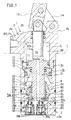
図1から図3Bは、本発明の一実施形態を示している。この実施形態では、倍力機構付きシリンダ装置をリンク式クランプに適用した場合を例示してある。まず、リリース状態を示す図1により、シリンダ装置の構造を説明する。
ハウジング1は、テーブル等の固定台Tに取り付けられている。そのハウジング1は、上側ハウジング2と、その上側ハウジング2の下側に螺合される下側ハウジング3とを有する。上側ハウジング2の上部に上端壁2aが形成されると共に、下側ハウジング3の下部に下端壁3aが形成される。その上側ハウジング2の内部に上側シリンダ孔5が形成されると共に、下側ハウジング3の内部に下側シリンダ孔6が形成される。1 to 3B show an embodiment of the present invention. In this embodiment, the case where the cylinder unit with a boosting mechanism is applied to a link clamp is illustrated. First, the structure of the cylinder device will be described with reference to FIG.
The housing 1 is attached to a fixing stand T such as a table. The housing 1 includes an upper housing 2 and a
上記の上側シリンダ孔5に第1ピストン10が上下方向に移動可能で保密状に挿入される。その第1ピストン10は、ピストン本体11と、そのピストン本体11から上下に突設された出力ロッド12とを有する。その出力ロッド12は、ピストン本体11から上方へ突設された上ロッド12aと、ピストン本体11から下方へ突設された下ロッド12bとを有する。 The first piston 10 is inserted in the upper cylinder hole 5 so as to be movable in the vertical direction and in a tightly sealed manner. The first piston 10 has a piston main body 11 and an
上記の上ロッド12aの上端部にクランプアーム13の左端部が垂直面内で回転可能に連結される。上側ハウジング2の右上部から枢支部2bが上方へ突設され、その枢支部2bの上端部にリンク部材14の下端部が回転可能に連結されると共に、リンク部材14の上端部にクランプアーム13の長手方向の途中部が回転可能に連結される。 The left end of the
上記の下側シリンダ孔6に倍力用の第2ピストン15が、上下方向に移動可能で保密状に挿入されると共に、上記の下ロッド12bの外周部に移動可能で保密状に外嵌めさせる。 The
上記のピストン10のピストン本体11と第2ピストン15との間にロック室16が形成される。そのロック室16に、ロック用の圧力流体としての圧油が、ロック給排路17とロックポートP1とを介して供給及び排出される。
また、ピストン本体11の上側に第1リリース室20が形成されると共に、第2ピストン15の下側に第2リリース室21が形成される。上記の上ロッド12aとピストン本体11と下ロッド12bとに形成された連通孔22が、第1リリース室20と第2リリース室21とを連通させる。これにより、第1リリース室20および第2リリース室21に圧油がリリース給排路23とリリースポートP2とを介して供給及び排出される。A lock chamber 16 is formed between the piston body 11 of the piston 10 and the
A
上記の下側シリンダ孔6の下部に形成された段差部3bに、環状の受止めスリーブ26が下方から受け止められる。その受止めスリーブ26の内周孔には、上記の下ロッド12bが上下方向に移動可能に挿入される。 An annular receiving
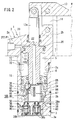
上記の第2リリース室21に倍力機構30が設けられ、その倍力機構30が、ロック室16の圧油によって第2ピストン15が下方へ作用する力を、上方へ倍力変換させて下ロッド12bに伝達する。その倍力機構30は、図2に示すように、次のように構成される。 A booster mechanism 30 is provided in the
上記の受止めスリーブ26の上部に案内溝31が、周方向に所定の間隔をあけて半径方向に形成される。その案内溝31に係合ボール32が左右方向へ移動可能に挿入される。上記の第2ピストン15の内周孔に倍力部33が、上方に向かうにつれて軸心に近づくように形成される。その倍力部33に係合ボール32が当接されている。上記の下ロッド12bの下部に伝達溝35が周方向に所定の間隔をあけて設けられ、その伝達溝35が上方に向かうにつれて軸心から遠ざかるように形成されている。その伝達溝35の周壁に伝達部36が係合ボール32に当接されている。 Guide grooves 31 are formed in the upper part of the receiving
前記下側ハウジング3の下端壁3aの左部に検出用の第1エア検出路38が形成される。その第1エア検出路38の途中部に第1検出弁(検出弁)40が設けられる。その第1検出弁40の上流側に第1供給路38aが形成されると共に、その第1検出弁40の下流側に第1排出路38bが形成される。
また、下端壁3aの右部に検出用の第2エア検出路39が形成される。その第2エア検出路39の途中部に第2検出弁60が設けられる。その第2検出弁60の上流側に第2供給路39aが形成されると共に、その第2検出弁60の下流側に第2排出路39bが形成される。A first
Further, a second
上記の第1検出弁40は、図3Aに示すように、次のように構成される。
上記の下端壁3aに第1装着孔41が第2リリース室21に連通されるように上下方向に形成される。その第1装着孔41は、下側から順に形成された雌ネジ孔42と中径孔43と小径孔44とを有する。その雌ネジ孔42と中径孔43との間に形成された段差部46に、第1環状押さえ47が、雌ネジ孔42に螺合される第1ケーシング48によって固定される。その第1ケーシング48の内部に弁室49が形成され、その弁室49に第1供給路38aが連通される。また、その弁室49に第1検出ロッド50が挿入される。その第1検出ロッド50の上端部が、封止部材51を介して小径孔44に上下方向に移動可能で挿入されると共に、第2リリース室21内に突出される。その第1検出ロッド50の途中高さ部に形成された大径部が、弁室49の内周壁に沿って上下方向に案内される。その大径部に溝50aが周方向に間隔をあけて上下方向に形成される。また、その第1検出ロッド50の下部に溝52が周方向に形成され、その溝52に第1弁体としてのOリング53が装着される。上記の弁室49に第1排出路38bが連通され、その第1排出路38bの周縁部に弁座54が形成される。上記の第1ケーシング48の下部と第1検出ロッド50の大径部との間に装着された圧縮バネ55が、第1検出ロッド50を上方へ付勢する。As shown in FIG. 3A, the
A first mounting
上記の第2検出弁60は、第1検出弁40と同じ構造であり、次のように構成される。
上記の下端壁3aに第2装着孔61が第2リリース室21に連通されるように上下方向に形成される。その第2装着孔61の雌ネジ孔62に第2ケーシング68が螺合され、その第2ケーシング68によって第1環状押さえ67が段差部66に固定される。その第2ケーシング68内に形成された弁室69に、第1供給路38aが連通される。また、その弁室69に第2検出ロッド70が挿入される。その第2検出ロッド70の上端部が、封止部材71を介して第2装着孔61の小径孔64に上下方向に移動可能で挿入されると共に、第2リリース室21内に突出される。その第2検出ロッド70の途中高さ部に形成された大径部が、弁室69の内周壁に沿って上下方向に案内される。その大径部に溝70aが周方向に間隔をあけて上下方向に形成される。その第2検出ロッド70の下部に溝72が周方向に形成され、その溝72に第2弁体としてのOリング73が装着される。上記の弁室69に第2排出路39bが連通され、その第2排出路39bの周縁部に弁座74が形成される。上記の第2ケーシング68の下部と第2検出ロッド70の大径部との間に装着された圧縮バネ75が、第2検出ロッド70を上方へ付勢する。The
A second mounting
上記の係合ボール32と第1検出ロッド50の上端部との間に被操作部材80が上下方向へ移動可能に挿入される。その被操作部材80は、下側から順に被操作リング81と被操作ピン82とを有する。その被操作リング81が、上記の下端壁3aと受止めスリーブ26との間に形成された隙間に上下移動可能に挿入されると共に、第1検出弁40の第1検出ロッド50の上面に当接されている。上記の被操作ピン82が、前記受止めスリーブ26に形成された装着孔に、上下移動可能に挿入される。その被操作ピン82の下端部が、上記の被操作リング81の上部に形成された凹部81aに挿入されることにより、その受止めスリーブ26と被操作リング81とが、周方向への位相が合致するように構成される。その被操作ピン82の上端部が係合ボール32に当接可能となるように受止めスリーブ26の前記案内溝31から上方へ突出される。
また、下ロッド12bの外周部からピン85が半径方向の外方へ突設される。また、受止めスリーブ26に案内溝86が上下方向へ形成され、その案内溝86に連続するように案内溝87が被操作リング81に上下方向へ形成される。これにより、そのピン85が案内溝86と案内溝87とに沿って上下方向に案内される。その結果、第1ピストン10と受止めスリーブ26とは、周方向への位相が合致するように構成される。また、第1ピストン10と被操作リング81とは、周方向への位相が合致するように構成される。The operated
Further, a
上記のシリンダ装置は、図1から図3Bに示すように、次のように作動する。
図1(及び図3A)に示すリリース状態では、ロック室16から圧油が排出されると共に、第1リリース室20および第2リリース室21に圧油が供給されている。これにより、第1リリース室20の圧油によって第1ピストン10が下方へ移動され、下ロッド12bの下端部が下端壁3bに下方から受け止められている。また、第2リリース21の圧油によって第2ピストン15が上昇位置へ移動され、その第2ピストン15が、上側シリンダ孔5の下端部に形成された段差部2cに上方から受け止められている。また、係合ボール32は、下ロッド12bの外周部によって半径方向の外方へ移動されている。The above-mentioned cylinder device operates as follows, as shown in FIGS. 1 to 3B.
In the release state shown in FIG. 1 (and FIG. 3A), the pressure oil is discharged from the lock chamber 16, and the pressure oil is supplied to the
また、図3Aに示すリリース状態では、第1検出弁40の圧縮バネ55が第1検出ロッド50と被操作リング81とを介して被操作ピン82を上方へ移動させている。このため、第1検出ロッド50のOリング53が弁座54から離間され、第1検出弁40が開弁されている。
また、下ロッド12bが第2検出弁60の圧縮バネ75に抗して第2検出ロッド70を下方へ移動させている。このため、第2検出ロッド70のOリング73が弁座74に封止係合され、第2検出弁60は閉弁されている。Further, in the release state shown in FIG. 3A, the
The
図1(及び図3A)のリリース状態から図2(及び図3B)のロック状態へロック駆動するときには、リリース状態において、第1リリース室20および第2リリース室21から圧油が排出されると共に、ロック室16に圧油が供給される。
すると、まず、ロック室16の圧油が、第1ピストン10を上方へ低負荷で移動させていくと、下ロッド12bも上昇される。すると、第2検出ロッド70が圧縮バネ75によって上方へ移動されていき、第2検出弁60が開弁される。また、係合ボール32が、受止めスリーブ26の案内溝31に下方から支持されると共に、下ロッド12bの外周部に半径方向の内方から支持される。このため、第2ピストン15が係合ボール32によって上昇位置で保持されている。
次いで、下ロッド12bの伝達部36が係合ボール32と同じ高さ位置まで当該下ロッド12bが上昇されると、その係合ボール32が半径方向の内方へ移動されることが許容される。引き続いて、第2ピストン15が下降されていくと、当該第2ピストン15が係合ボール32を半径方向の内方へ押し込み、上記の倍力機構30が倍力駆動を開始する。すると、係合ボール32が被操作ピン82と被操作リング81とを介して第1検出弁40の第1検出ロッド50を下方へ移動させていく。
最後に、図2に示すように、クランプアーム13の右端部がクランプ対象物Wを押圧すると、第1ピストン10が上昇位置で停止すると共に、第2ピストン15が下降位置で停止する。このときに、係合ボール32が被操作ピン82と被操作リング81とを介して第1検出ロッド50を下方へ移動させることにより、第1検出ロッド50のOリング53が弁座54に当接されて第1検出弁40が閉弁される。これにより、第1エア供給路38a側の上昇圧力を圧力センサ(図示せず)が検出する。その結果、上記の倍力機構30が倍力駆動していることが検知される。When the lock drive is performed from the release state of FIG. 1 (and FIG. 3A) to the lock state of FIG. 2 (and FIG. 3B), pressure oil is discharged from the
Then, first, when the pressure oil in the lock chamber 16 moves the first piston 10 upward with a low load, the
Next, when the
Finally, as shown in FIG. 2, when the right end portion of the
図2(3B)のロック状態から図1(図3A)のリリース状態へリリース駆動するときには、ロック状態において、ロック室16から圧油が排出されると共に、第1リリース室20および第2リリース室21に圧油が供給される。
すると、まず、第2リリース室21の圧油が第2ピストン15を上方へ移動させていくと、係合ボール32が半径方向の外方へ移動されることが許容される。
次いで、第1リリース室20の圧油が第1ピストン10を下降させていくと、下ロッド12bの伝達部36が係合ボール32を半径方向の外方へ移動させていく。すると、第1検出弁40の圧縮バネ55が、第1検出弁40の第1検出ロッド50と被操作リング81と被操作ピン82とを上方へ移動していく。すると、第1検出弁40のOリング53が弁座54から離間され、第1検出弁40が開弁される。これにより、第1エア供給路38a側の下降圧力を圧力センサ(図示せず)によって検出する。
最後に、第2ピストン15が、上側ハウジング2の段差部2cに上方から受け止められる。また、下ロッド12bが第2検出弁60の検出ロッド70を下限位置に移動させると共に、その下ロッド12bが下端壁3aに受け止められる。これにより、第2検出弁60が閉弁される。その結果、第2エア供給路39a側の上昇圧力を圧力センサ(図示せず)が検出することにより、第2検出弁60によって下ロッド12bが下限位置に移動したことが検出される。When release driving from the locked state of FIG. 2 (3B) to the released state of FIG. 1 (FIG. 3A), the pressure oil is discharged from the lock chamber 16 in the locked state, and the
Then, first, when the pressure oil in the
Next, when the pressure oil in the
Finally, the
上記の実施形態は次の作用効果を奏する。
上記のシリンダ装置をロック駆動するときには、上記の第2ピストン15が係合ボール32を半径方向の内方へ移動させることにより、その係合ボール32が第1検出ロッド50を下方に移動させる。このため、上記の第1検出ロッド50は、第2ピストンによって直接に下方に移動される従来技術の第1検出ロッドに比べて、移動距離を大幅に短くできる。従って、第1検出ロッド50の移動を許容する弁室49を小さく製作できる。その結果、第1検出弁40の全体寸法を小さくでき、その第1検出弁40に付設されたシリンダ装置をコンパクトに造ることができる。The above embodiment has the following effects.
When the cylinder device is locked, the
上記の各実施形態は次のように変更可能である。
上記の圧力流体は、例示した圧油に代えて、他の液体または圧縮空気等の気体であってもよい。
上記の検出弁40,60が、下端壁3aに設けられるのに代えて、上端壁2aにもうけてもよい。また、上記の検出弁40,60の配置姿勢を、例示の縦向きに代えて、斜め向きとしてもよい。
また、検出弁40,60に代えて、電気式のスイッチ、例えば、接触式のリミットスイッチ、近接スイッチ等の非接触式のスイッチによって係合ボール32の動きを検出してもよい。さらには、電気式のスイッチではなく、半導体素子などを用いた電子式のスイッチであってもよい。
上記の第1ピストン10をロック駆動させるときに、リリース状態から上方へ低負荷で駆動させ、その後、倍力駆動させるのに代えて、リリース状態からロック状態まで倍力駆動させてもよい。
上記の倍力機構30は、ロック室16の圧油から第2ピストン15に下方へ作用する力を上方へ倍力変換して出力ロッド12に伝達するのに代えて、ロック室16の圧油から第2ピストン15に上方へ作用する力を下方へ倍力変換して出力ロッド12に伝達してもよい。
上記の被操作部材80は、前記係合ボール32と前記検出弁40との間に上下方向へ移動可能に設けられるのに代えて、上下方向から傾斜された方向へ移動可能に設けられてもよい。
上記の被操作部材80が有する被操作リング81と被操作ピン82とが、別々に形成されるのに代えて、一体に形成されてもよい。
その他に、当業者が想定できる範囲で種々の変更を行えることは勿論である。The above embodiments can be modified as follows.
The pressure fluid described above may be another liquid or a gas such as compressed air instead of the illustrated pressure oil.
The
Also, instead of the
When the first piston 10 is driven to be locked, the first piston 10 may be driven from the released state upward with a low load, and then may be boosted from the released state to the locked state instead of being driven by the boost.
The booster mechanism 30 described above replaces the force acting downward on the
The above-described operated
The operated ring 81 and the operated pin 82 included in the operated
Besides, it goes without saying that various modifications can be made as far as the person skilled in the art can conceive.
1:ハウジング,10:第1ピストン,12:出力ロッド,15:第2ピストン,30:倍力機構,32:係合ボール,38:エア検出路(第1エア検出路),40:検出弁(第1検出弁),50:検出ロッド(第1検出ロッド),80:被操作部材.1: housing, 10: first piston, 12: output rod, 15: second piston, 30: booster mechanism, 32: engagement ball, 38: air detection path (first air detection path), 40: detection valve (First detection valve), 50: detection rod (first detection rod), 80: operated member.
Claims (3)
前記出力ロッド(12)の外周部に保密状に外嵌めされると共に、前記ハウジング(1)内に上下方向に移動可能で保密状に挿入された倍力用の第2ピストン(15)と、
ロック用の圧力流体から前記第2ピストン(15)に作用する力を倍力変換して前記出力ロッド(12)に伝達する倍力機構(30)であって、前記出力ロッド(12)と前記第2ピストン(15)との間に当該出力ロッド(12)の半径方向に移動可能に設けられた係合ボール(32)を有する倍力機構(30)と、
前記ハウジング(1)内に形成された検出用のエア検出路(38)と、
前記ハウジング(1)に設けられた検出弁(40)であって、前記係合ボール(32)が当該検出弁(40)の検出ロッド(50)を前記半径方向に対して交差する方向に移動させることにより前記検出用のエア検出路(38)を開閉する検出弁(40)と、を備える、
ことを特徴とするシリンダ装置。 A first piston (10) for forward and backward movement, which is vertically movable in a housing (1) and hermetically inserted, and has an output rod (12);
A second piston (15) for boosting that is fitted in a tightly-fitting manner on the outer periphery of the output rod (12) and is movable in the vertical direction into the housing (1) and inserted in a tightly-fitting manner;
A boosting mechanism (30) that boosts the force acting on the second piston (15) from pressure fluid for locking and transmits it to the output rod (12), the output rod (12) and the above A booster mechanism (30) having an engagement ball (32) movably provided in the radial direction of the output rod (12) between the second piston (15);
An air detection path (38) for detection formed in the housing (1);
Wherein a housing detecting valve provided in (1) (40), moves the detection rod (50) of the engaging ball (32) is the detection valve (40) in a direction intersecting the radial direction And a detection valve (40) for opening and closing the air detection path (38) for detection.
A cylinder device characterized by that.
前記係合ボール(32)と前記検出ロッド(50)との間に被操作部材(80)が前記半径方向に対して交差する方向へ移動可能に設けられ、
前記係合ボール(32)が前記半径方向へ移動したときに、当該係合ボール(32)が前記被操作部材(80)を介して検出ロッド(50)を前記半径方向に対して交差する方向へ移動させる、ことを特徴とするシリンダ装置。 The cylinder device according to claim 1, wherein
The operated member (80) is movable in a direction intersecting the radial direction between the engaging ball (32) and the detection rod (50),
When the engaging ball (32) is moved to the radial direction, the direction the engaging ball (32) is crossing the detection rod via the operated member (80) (50) with respect to the radial direction To move to the cylinder device.
前記出力ロッド(12)の外周部に保密状に外嵌めされると共に、前記ハウジング(1)内に上下方向に移動可能で保密状に挿入された倍力用の第2ピストン(15)と、
ロック用の圧力流体から前記第2ピストン(15)に作用する力を倍力変換して前記出力ロッド(12)に伝達する倍力機構(30)であって、前記出力ロッド(12)と前記第2ピストン(15)との間に当該出力ロッド(12)の半径方向に移動可能に設けられた係合ボール(32)を有する倍力機構(30)と、
検出ロッドを有するスイッチと、を備え、
そのスイッチは、前記係合ボール(32)が当該スイッチの検出ロッドを前記半径方向に対して交差する方向へ移動させることを電気的または電子的に検出する、ことを特徴とするシリンダ装置。 A first piston (10) for forward and backward movement, which is vertically movable in a housing (1) and hermetically inserted, and has an output rod (12);
A second piston (15) for boosting that is fitted in a tightly-fitting manner on the outer periphery of the output rod (12) and is movable in the vertical direction into the housing (1) and inserted in a tightly-fitting manner;
A boosting mechanism (30) that boosts the force acting on the second piston (15) from pressure fluid for locking and transmits it to the output rod (12), the output rod (12) and the above A booster mechanism (30) having an engagement ball (32) movably provided in the radial direction of the output rod (12) between the second piston (15);
A switch having a detection rod,
Such a switch, the engagement ball (32) is electrically or electronically detect moving in a direction intersecting the detection rod of the switch to the radial direction and cylinder device according to claim.
Priority Applications (6)
| Application Number | Priority Date | Filing Date | Title |
|---|---|---|---|
| JP2015140846A JP6552310B2 (en) | 2015-06-26 | 2015-06-26 | Cylinder device |
| US15/574,586 US10385889B2 (en) | 2015-06-26 | 2016-06-13 | Cylinder device |
| KR1020177034674A KR102342061B1 (en) | 2015-06-26 | 2016-06-13 | Cylinder apparatus |
| EP16814214.9A EP3315793B1 (en) | 2015-06-26 | 2016-06-13 | Cylinder apparatus |
| PCT/JP2016/067561 WO2016208443A1 (en) | 2015-06-26 | 2016-06-13 | Cylinder apparatus |
| CN201680036338.XA CN107735576B (en) | 2015-06-26 | 2016-06-13 | Cylinder device |
Applications Claiming Priority (1)
| Application Number | Priority Date | Filing Date | Title |
|---|---|---|---|
| JP2015140846A JP6552310B2 (en) | 2015-06-26 | 2015-06-26 | Cylinder device |
Publications (3)
| Publication Number | Publication Date |
|---|---|
| JP2017015237A JP2017015237A (en) | 2017-01-19 |
| JP2017015237A5 JP2017015237A5 (en) | 2018-03-15 |
| JP6552310B2 true JP6552310B2 (en) | 2019-07-31 |
Family
ID=57585691
Family Applications (1)
| Application Number | Title | Priority Date | Filing Date |
|---|---|---|---|
| JP2015140846A Active JP6552310B2 (en) | 2015-06-26 | 2015-06-26 | Cylinder device |
Country Status (6)
| Country | Link |
|---|---|
| US (1) | US10385889B2 (en) |
| EP (1) | EP3315793B1 (en) |
| JP (1) | JP6552310B2 (en) |
| KR (1) | KR102342061B1 (en) |
| CN (1) | CN107735576B (en) |
| WO (1) | WO2016208443A1 (en) |
Families Citing this family (7)
| Publication number | Priority date | Publication date | Assignee | Title |
|---|---|---|---|---|
| JP6688644B2 (en) * | 2016-03-02 | 2020-04-28 | 株式会社コスメック | Clamp device with lift function |
| KR101879840B1 (en) * | 2018-01-31 | 2018-07-19 | 한국에스엠씨공압(주) | Stopper Cylinder |
| US11207752B2 (en) * | 2018-03-14 | 2021-12-28 | Kosmek Ltd. | LNK type clamp device |
| EP3800358B1 (en) | 2018-08-17 | 2022-11-02 | Kosmek Ltd. | Cylinder device |
| JP7193122B2 (en) * | 2018-10-22 | 2022-12-20 | 株式会社コスメック | work support |
| CN112024602A (en) * | 2020-08-14 | 2020-12-04 | 湖南科美达重工有限公司 | Double-stroke expansion and contraction oil cylinder |
| CN115401523B (en) * | 2022-08-31 | 2024-01-09 | 东风设备制造有限公司 | Double-sided clamp with one-way air inlet and two-sided independent action and no-material air detection device |
Family Cites Families (17)
| Publication number | Priority date | Publication date | Assignee | Title |
|---|---|---|---|---|
| US3661053A (en) * | 1970-12-04 | 1972-05-09 | Parker Hannifin Corp | Reversing switch actuator for fluid motor |
| FR2270469B1 (en) * | 1974-03-27 | 1977-03-04 | Messier Hispano Sa | |
| JPS55155903A (en) * | 1979-05-23 | 1980-12-04 | Okazaki Sangyo Kk | Air cylinder with booster mechanism |
| US4890541A (en) * | 1988-06-20 | 1990-01-02 | Spooner Richard C | Fluid-operated actuator with force multiplication |
| EP1965176B1 (en) * | 2007-03-01 | 2014-07-30 | J. Wagner AG | Sensor for recording the position of a moveable magnetic object and a conveyor device equipped with the sensor |
| JP4945681B1 (en) * | 2010-11-24 | 2012-06-06 | 株式会社コスメック | Cylinder device with booster mechanism |
| JP5129378B1 (en) * | 2011-08-26 | 2013-01-30 | 株式会社コスメック | Cylinder device with booster mechanism |
| KR101653895B1 (en) * | 2012-02-16 | 2016-09-02 | 가부시키가이샤 코스멕 | Cylinder device with force multiplier |
| JP6012445B2 (en) * | 2012-11-13 | 2016-10-25 | パスカルエンジニアリング株式会社 | Fluid pressure cylinder and swivel clamp device |
| JP5951461B2 (en) * | 2012-12-03 | 2016-07-13 | パスカルエンジニアリング株式会社 | Fluid pressure cylinder and swivel clamp device |
| JP6092710B2 (en) * | 2013-01-22 | 2017-03-08 | 株式会社コスメック | Cylinder device |
| JP6208480B2 (en) | 2013-06-11 | 2017-10-04 | 株式会社コスメック | Cylinder device with booster mechanism |
| JP6285655B2 (en) * | 2013-07-16 | 2018-02-28 | パスカルエンジニアリング株式会社 | Clamping device |
| CN104696306A (en) * | 2013-12-10 | 2015-06-10 | 贵州红林机械有限公司 | Mechanical follow-up oil cylinder assembly |
| JP6298294B2 (en) * | 2013-12-12 | 2018-03-20 | 株式会社コスメック | Cylinder device |
| CN104214168B (en) * | 2014-08-27 | 2016-09-14 | 华中科技大学无锡研究院 | A kind of bilaterally adjustable Quick cylinder of power output |
| JP5889374B2 (en) * | 2014-09-09 | 2016-03-22 | 株式会社コスメック | Cylinder device with booster mechanism |
-
2015
- 2015-06-26 JP JP2015140846A patent/JP6552310B2/en active Active
-
2016
- 2016-06-13 KR KR1020177034674A patent/KR102342061B1/en active IP Right Grant
- 2016-06-13 WO PCT/JP2016/067561 patent/WO2016208443A1/en active Application Filing
- 2016-06-13 US US15/574,586 patent/US10385889B2/en active Active
- 2016-06-13 CN CN201680036338.XA patent/CN107735576B/en active Active
- 2016-06-13 EP EP16814214.9A patent/EP3315793B1/en active Active
Also Published As
| Publication number | Publication date |
|---|---|
| JP2017015237A (en) | 2017-01-19 |
| CN107735576A (en) | 2018-02-23 |
| EP3315793B1 (en) | 2020-08-19 |
| WO2016208443A1 (en) | 2016-12-29 |
| CN107735576B (en) | 2019-12-03 |
| KR102342061B1 (en) | 2021-12-21 |
| EP3315793A1 (en) | 2018-05-02 |
| US20180156249A1 (en) | 2018-06-07 |
| EP3315793A4 (en) | 2019-03-20 |
| KR20180020967A (en) | 2018-02-28 |
| US10385889B2 (en) | 2019-08-20 |
Similar Documents
| Publication | Publication Date | Title |
|---|---|---|
| JP6552310B2 (en) | Cylinder device | |
| JP6641358B2 (en) | Cylinder device | |
| TWI518273B (en) | Two-way valve | |
| JP5827602B2 (en) | Clamping device | |
| JP5247298B2 (en) | Suck back valve | |
| JP6298294B2 (en) | Cylinder device | |
| JP6208480B2 (en) | Cylinder device with booster mechanism | |
| JP5939950B2 (en) | Cylinder device with booster mechanism | |
| KR102158175B1 (en) | Swivel clamp | |
| JP5859596B2 (en) | Work support | |
| JP2005104332A (en) | Master cylinder device | |
| JP4860506B2 (en) | Control valve | |
| JP6567916B2 (en) | Coupling device | |
| JP7458019B2 (en) | On-off valve device | |
| JP6971454B2 (en) | Cylinder device with detection valve | |
| JP2014196828A (en) | Cylinder device with booster mechanism | |
| JP2023003139A (en) | Cylinder device | |
| JP6906240B2 (en) | Cylinder device with booster mechanism | |
| JP2017062022A (en) | Cylinder device | |
| TW202024489A (en) | Fluid pressure cylinder | |
| JP6730767B2 (en) | Cylinder device with position detection function | |
| JP2014194284A (en) | Cylinder device with booster mechanism | |
| JP2023510558A (en) | Connection device with movable bushing | |
| JP2015059590A (en) | Fluid pressure cylinder |
Legal Events
| Date | Code | Title | Description |
|---|---|---|---|
| A521 | Request for written amendment filed |
Free format text: JAPANESE INTERMEDIATE CODE: A523 Effective date: 20180130 |
|
| A621 | Written request for application examination |
Free format text: JAPANESE INTERMEDIATE CODE: A621 Effective date: 20180130 |
|
| A131 | Notification of reasons for refusal |
Free format text: JAPANESE INTERMEDIATE CODE: A131 Effective date: 20181204 |
|
| A521 | Request for written amendment filed |
Free format text: JAPANESE INTERMEDIATE CODE: A523 Effective date: 20181221 |
|
| A131 | Notification of reasons for refusal |
Free format text: JAPANESE INTERMEDIATE CODE: A131 Effective date: 20190423 |
|
| A521 | Request for written amendment filed |
Free format text: JAPANESE INTERMEDIATE CODE: A523 Effective date: 20190603 |
|
| TRDD | Decision of grant or rejection written | ||
| A01 | Written decision to grant a patent or to grant a registration (utility model) |
Free format text: JAPANESE INTERMEDIATE CODE: A01 Effective date: 20190625 |
|
| A61 | First payment of annual fees (during grant procedure) |
Free format text: JAPANESE INTERMEDIATE CODE: A61 Effective date: 20190702 |
|
| R150 | Certificate of patent or registration of utility model |
Ref document number: 6552310 Country of ref document: JP Free format text: JAPANESE INTERMEDIATE CODE: R150 |
|
| R250 | Receipt of annual fees |
Free format text: JAPANESE INTERMEDIATE CODE: R250 |
|
| R250 | Receipt of annual fees |
Free format text: JAPANESE INTERMEDIATE CODE: R250 |