JP6548405B2 - phantom - Google Patents
phantom Download PDFInfo
- Publication number
- JP6548405B2 JP6548405B2 JP2015037431A JP2015037431A JP6548405B2 JP 6548405 B2 JP6548405 B2 JP 6548405B2 JP 2015037431 A JP2015037431 A JP 2015037431A JP 2015037431 A JP2015037431 A JP 2015037431A JP 6548405 B2 JP6548405 B2 JP 6548405B2
- Authority
- JP
- Japan
- Prior art keywords
- target
- base material
- phantom
- measurement
- targets
- Prior art date
- Legal status (The legal status is an assumption and is not a legal conclusion. Google has not performed a legal analysis and makes no representation as to the accuracy of the status listed.)
- Expired - Fee Related
Links
Images


Classifications
-
- A—HUMAN NECESSITIES
- A61—MEDICAL OR VETERINARY SCIENCE; HYGIENE
- A61B—DIAGNOSIS; SURGERY; IDENTIFICATION
- A61B5/00—Measuring for diagnostic purposes; Identification of persons
- A61B5/0093—Detecting, measuring or recording by applying one single type of energy and measuring its conversion into another type of energy
- A61B5/0095—Detecting, measuring or recording by applying one single type of energy and measuring its conversion into another type of energy by applying light and detecting acoustic waves, i.e. photoacoustic measurements
-
- A—HUMAN NECESSITIES
- A61—MEDICAL OR VETERINARY SCIENCE; HYGIENE
- A61B—DIAGNOSIS; SURGERY; IDENTIFICATION
- A61B8/00—Diagnosis using ultrasonic, sonic or infrasonic waves
- A61B8/58—Testing, adjusting or calibrating the diagnostic device
- A61B8/587—Calibration phantoms
-
- G—PHYSICS
- G09—EDUCATION; CRYPTOGRAPHY; DISPLAY; ADVERTISING; SEALS
- G09B—EDUCATIONAL OR DEMONSTRATION APPLIANCES; APPLIANCES FOR TEACHING, OR COMMUNICATING WITH, THE BLIND, DEAF OR MUTE; MODELS; PLANETARIA; GLOBES; MAPS; DIAGRAMS
- G09B23/00—Models for scientific, medical, or mathematical purposes, e.g. full-sized devices for demonstration purposes
- G09B23/28—Models for scientific, medical, or mathematical purposes, e.g. full-sized devices for demonstration purposes for medicine
- G09B23/286—Models for scientific, medical, or mathematical purposes, e.g. full-sized devices for demonstration purposes for medicine for scanning or photography techniques, e.g. X-rays, ultrasonics
-
- A—HUMAN NECESSITIES
- A61—MEDICAL OR VETERINARY SCIENCE; HYGIENE
- A61B—DIAGNOSIS; SURGERY; IDENTIFICATION
- A61B8/00—Diagnosis using ultrasonic, sonic or infrasonic waves
- A61B8/08—Detecting organic movements or changes, e.g. tumours, cysts, swellings
- A61B8/0825—Detecting organic movements or changes, e.g. tumours, cysts, swellings for diagnosis of the breast, e.g. mammography
-
- A—HUMAN NECESSITIES
- A61—MEDICAL OR VETERINARY SCIENCE; HYGIENE
- A61B—DIAGNOSIS; SURGERY; IDENTIFICATION
- A61B8/00—Diagnosis using ultrasonic, sonic or infrasonic waves
- A61B8/40—Positioning of patients, e.g. means for holding or immobilising parts of the patient's body
- A61B8/406—Positioning of patients, e.g. means for holding or immobilising parts of the patient's body using means for diagnosing suspended breasts
Description
本発明は、装置の評価用のファントムに関し、特に、光音響波による測定と、超音波エコーによる測定とを行える装置の評価用のファントムに関する。 The present invention relates to a phantom for evaluation of a device, and more particularly to a phantom for evaluation of a device capable of performing measurement by photoacoustic wave and measurement by ultrasonic echo.
光イメージング技術の一つとして、PAT(PhotoAcoustic Tomography;光音響トモグラフィー)が知られている。光音響トモグラフィーにおいては、被検査物に対してパルス光を照射することで、被検査物のうち、光のエネルギーを吸収した領域から発生した音響波(以下、光音響波とも記す)を検出する。検出された光音響波から、被検査物内部の光学特性値に関する情報を可視化することができる。 PAT (PhotoAcoustic Tomography; photoacoustic tomography) is known as one of the optical imaging techniques. In photoacoustic tomography, by applying pulsed light to an object to be inspected, an acoustic wave (hereinafter also referred to as photoacoustic wave) generated from a region of the object to be inspected that has absorbed light energy is detected. . From the detected photoacoustic wave, it is possible to visualize information on the optical characteristic value inside the inspection object.
PAT技術は、超音波エコー技術と併用することが知られており、特許文献1には、光音響波の測定により、被検者の胸の組織の新生血管の分布を得るとともに、超音波エコーにより、被検者の形態学画像を得る装置が記載されている。 PAT technology is known to be used in combination with ultrasound echo technology, and Patent Document 1 discloses the distribution of neovessels in the chest tissue of a subject by measurement of photoacoustic waves, as well as ultrasound echo. Describes an apparatus for obtaining a morphological image of a subject.
また、一般に、PAT装置の性能を評価するために、既知の内部構造を有するファントムが利用される。このファントムを被検査物として得られた光音響波による画像から、PAT装置の性能を評価することができる。特許文献2には、人体組織を模したファントムが記載されている。 Also, in general, phantoms with known internal structures are used to evaluate the performance of PAT devices. The performance of the PAT apparatus can be evaluated from the image by the photoacoustic wave obtained by using this phantom as an inspection object. Patent Document 2 describes a phantom imitating human tissue.
しかしながら、超音波エコーによる測定も行えるPAT装置を評価するのに好適なファントムの構成は、従来検討されていなかった。本発明は、超音波エコーによる測定も行えるPAT装置の評価に好適なファントムを提供することを目的とする。 However, the configuration of a phantom suitable for evaluating a PAT apparatus that can also perform measurement by ultrasonic echo has not been considered conventionally. An object of the present invention is to provide a phantom suitable for evaluation of a PAT apparatus which can also perform measurement by ultrasonic echo.
上記目的を達成する本発明の一つの側面であるファントムは、測定面を有する母材と、前記母材の中に設けられた第1のターゲットおよび第2のターゲットと、を有するファントムであって、前記第1のターゲットと前記母材との音響特性の差は、前記第2のターゲットと前記母材との音響特性の差よりも小さく、前記第2のターゲットと前記母材との光学特性の差は、前記第1のターゲットと前記母材との光学特性の差よりも小さく、さらに、前記第2のターゲットは、前記測定面から、前記測定面と直交する方向において、前記第1のターゲットよりも離れた位置に設けられたことを特徴とする。 A phantom, which is an aspect of the present invention to achieve the above object, is a phantom having a base material having a measurement surface, and a first target and a second target provided in the base material. The difference between the acoustic characteristics of the first target and the base material is smaller than the difference between the acoustic characteristics of the second target and the base material, and the optical characteristics of the second target and the base material the difference is smaller than the difference in optical characteristics between the first target and said base material, further, the second target, before Symbol measurement surface, in a direction perpendicular to the measuring surface, the first It is characterized in that it is provided at a position distant from the target of .
本発明の別の側面であるファントムは、測定面を有する母材と、前記母材の中に設けられた、第1のターゲットと第2のターゲットとを有するファントムであって、前記第1のターゲットは、前記第2のターゲットよりも光を吸収しやすく、前記第2のターゲットは、前記第1のターゲットよりも音響波を反射しやすく、さらに、前記第2のターゲットは、前記測定面から、前記測定面と直交する方向において、前記第1のターゲットよりも離れた位置に設けられたことを特徴とする。 A phantom according to another aspect of the present invention is a phantom including a base material having a measurement surface, and a first target and a second target provided in the base material, wherein the first target is a phantom . The target absorbs light more easily than the second target, the second target reflects the acoustic wave more easily than the first target, and the second target receives the light from the measurement surface. The device is characterized in that it is provided at a position farther from the first target in a direction orthogonal to the measurement surface .
超音波エコーによる測定も行えるPAT装置の評価に好適なファントムが得られる。 The phantom suitable for evaluation of the PAT apparatus which can also perform measurement by ultrasonic echo is obtained.
本発明が解決しようとする課題の理解を容易にするために、まず、PAT装置(以下では、光音響装置とも記す)用のファントムについて説明する。 In order to facilitate understanding of the problem to be solved by the present invention, first, a phantom for a PAT apparatus (hereinafter also referred to as a photoacoustic apparatus) will be described.
PAT装置の評価に使われるファントムは、光音響波の測定に適したターゲットを有する。このターゲットは、トランスデューサによって検出できる程度の強度を持つ光音響波を生成するのに十分なだけの光の吸収率を有する。しかし、光音響波の生成に適したターゲット材料は、超音波エコーの測定には適さないことが多い。そのため、従来のPAT装置用のファントムでは、超音波エコーによる測定も行えるPAT装置の評価に適さないおそれがある。 The phantom used to evaluate the PAT apparatus has a target suitable for photoacoustic wave measurement. The target has an absorptivity for light sufficient to generate a photoacoustic wave having an intensity that can be detected by the transducer. However, target materials suitable for generating photoacoustic waves are often not suitable for measuring ultrasound echoes. Therefore, the phantom for the conventional PAT apparatus may not be suitable for evaluation of the PAT apparatus which can also perform measurement by ultrasonic echo.
そこで、光音響波の生成に適したターゲットを持つファントムと、超音波エコーによる測定に適したターゲットを持つファントムとを用意して、評価する対象に応じてファントムを交換する方法が考えられる。しかし、その場合には、測定に応じてファントムを交換することは、操作者にとって負担となる。 Therefore, a method is conceivable in which a phantom having a target suitable for generating a photoacoustic wave and a phantom having a target suitable for measurement by ultrasonic echo are prepared, and the phantom is exchanged according to an object to be evaluated. However, in that case, replacing the phantom according to the measurement is a burden on the operator.
そのため、本発明では、同一のファントムに、光音響波の測定に適したターゲットと、超音波エコーの測定に適したターゲットとをともに有するファントムとした。特に、ファントム内のターゲットの好適な配置を見出した。以下では、本発明の実施形態に係るファントムを説明する。以下では、光音響波の測定に適したターゲットを光音響測定用ターゲットと呼び、超音波エコーの測定に適したターゲットを超音波測定用ターゲットと呼ぶ。 Therefore, in the present invention, the same phantom is a phantom having both a target suitable for measuring a photoacoustic wave and a target suitable for measuring an ultrasonic echo. In particular, a preferred arrangement of targets in the phantom has been found. Hereinafter, a phantom according to an embodiment of the present invention will be described. Hereinafter, a target suitable for measuring photoacoustic waves is referred to as a target for measuring photoacoustics, and a target suitable for measuring ultrasonic echoes is referred to as a target for measuring ultrasonic waves.
(第1の実施形態)
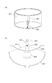
図1(a)は、本発明の第1の実施形態に係るファントムを示す図である。ファントムは、外枠101によって囲まれた領域に、母材102が充填されており、母材102の一部に、第1のターゲットである光音響測定用ターゲット103と第2のターゲットである超音波測定用ターゲット104とが設けられている。本実施形態においては、光音響測定用ターゲット103および超音波測定用ターゲット104はともに円柱形状で、x軸に沿って設けられている。図1(a)では、理解を容易にするために、外枠101が母材102のz−y面を覆わない例を示しているが、母材102のz−y面を覆うようにしても良い。
First Embodiment
FIG. 1A is a view showing a phantom according to a first embodiment of the present invention. In the phantom, a
外枠は、母材102の形状を保つための支持部材としての役割を果たすものである。本実施形態においては、z軸と直交する面は、測定面105として母材102が露出する。支持部材は、母材よりも剛性が高いものを用いることで、特に母材102が柔らかい場合には、ファントムの取り扱いを容易にすることができる。また、母材102は、測定面とは異なる面を介して支持部材に固定されるが、図1(a)に示すように、母材102の測定面を露出させてもよいし、光音響測定に利用する光の波長に対して透明なものであれば、母材102の測定面を覆う保護部材を設けても良い。保護部材は、支持部材と一体的に構成されていても良い。なお、PAT装置の評価を行う際には、測定面に近接するように探触子が配置される。
The outer frame serves as a support member for maintaining the shape of the
光音響測定用ターゲット103は、光音響測定の際に検出されるとともに、超音波エコーによる測定の際には観察されにくいことを目的としている。このターゲットは、PAT装置によって得られる初期音圧分布の画像コントラスト、酸素飽和度や解像度等を評価するためのものである。そのため、超音波エコーによる測定では観察されにくい構成となっている。具体的には、光音響測定用ターゲット103内部の音速や音響減衰のような音響特性が母材に近くて、光の吸収係数等の光学的特性が母材と異なるものである。
The
超音波測定用ターゲット104は、超音波エコー測定の際に観察されるとともに、光音響測定の際には観察されにくいことを目的としている。このターゲットは、超音波エコー測定によって得られる画像コントラストや解像度などを評価するためのものである。そのため、音速や減衰率等の音響特性が母材と異なり、光の吸収係数等の光学特性が母材に近くて低いものである。
The
以上を踏まえると、光音響測定用ターゲット103と母材102との音響特性の差は、超音波測定用ターゲット104と母材102との音響特性の差よりも小さい。さらに、超音波測定用ターゲット104と母材102との光学特性の差は、光音響測定用ターゲット103と母材102との光学特性の差よりも小さいと言える。また、別の言い方をすると、光音響測定用ターゲット103は、超音波測定用ターゲットよりも光を吸収しやすく、超音波測定用ターゲット104は、光音響測定用ターゲット103よりも音響波を反射しやすいとも言える。
Based on the above, the difference between the acoustic characteristics of the
上述の特性を満たすための材料を次に説明する。 Materials for meeting the above-mentioned characteristics are described below.
本実施形態において、光音響測定用ターゲット103は、母材102と同様の材料で作製しても良い。母材102と共通の材料を使うことにより、音響特性を互いに近い値にすることができるので、光音響測定用ターゲット103が超音波測定時に観察されにくくなる。母材102は、ポリオールと、ポリオールに分散可能なフィラーから成ってもよい。ポリオールとしては、ポリエーテルポリオール、ポリエステルポリオール、ポリカーボネートポリオール等を挙げることができる。このうち、ポリエーテルポリオールは、人体組織の音響伝播特性に関する相関性の点においてより好ましい。なお、ポリオールは通常では液体状態であり、必要に応じて硬化剤を含ませることにより固体状に樹脂を硬化させることが可能である。人体組織の音響伝播特性に近似させる上では、イソシアネート化合物を用いることが好ましい。
In the present embodiment, the
また、母材102および光音響測定用ターゲット103を人体組織の光伝播特性に近似させるためには、フィラーの分散により光の等価散乱係数と吸収係数を適当な値にする必要がある。光散乱性を有する光散乱性フィラーとしては、酸化チタン等の無機酸化物が挙げられる。また、光吸収性を有する光吸収性フィラーとしては、顔料を用いることが望ましい。顔料としてはカーボンブラックのような黒色顔料、銅フタロシアニン等のシアン顔料、モノアゾレーキ系顔料、モノアゾ系顔料等のマゼンダ顔料、およびジアリライドイエロー等のイエロー顔料などが挙げられる。
Further, in order to approximate the
超音波測定用ターゲット104の一例として、主剤としてのポリブタジェンポリオールを希釈し、これに硬化剤としてのジフェニルメタンジイソシアネートを反応させて得たウレタン樹脂が考えられる。このウレタン樹脂に有機体フィラーを添加して、超音波の反射および散乱が均一になるようにする。なお、有機粉体フィラーは、ポリプロピレン、ポリエチレン、エチレン・酢酸ビニル、ビニルアルコール共重合体等の粉体を利用することができる。
As an example of the
次に、母材102中の各ターゲットの形状および配置について説明する。図1(b)は、本実施形態に係るファントムのz−y平面における断面図である。
Next, the shape and arrangement of each target in the
本実施形態において、母材102はx、y、z各軸に沿う向きにそれぞれ60mm、80mm、60mmの大きさを持つ立方体である。一方、光音響測定用ターゲット103は、φ1mmの円柱形状で、測定面105から10mmの深さに、x軸に平行に設けられている。また、超音波測定用ターゲット104は、φ1mmの円柱形状で、測定面から20mmの深さに、x軸に平行に設けられている。本実施形態では、光音響測定用ターゲット103および超音波測定用ターゲット104は、y座標は同じで、z軸方向が異なるように配置されている。なお、各ターゲットの形状は円柱に限らず、球などでもよいが、型に樹脂を流して成型するため、円柱等の柱形状であると、再現性良く作製できる点で望ましい。
In the present embodiment, the
図1(b)において、各ターゲットと測定面105との間に結ばれた点線は、x軸方向に延在するリニアタイプの超音波プローブ(不図示)を用いた場合に、超音波プローブによって検知される音響波の範囲を示す音線である。一般的に、リニアタイプの超音波プローブは、探触子の中心線上にターゲットを置いたときに、解像度などの特性が良い。そのため、各ターゲットの配置を図1に示す構成にすることで、超音波プローブを動かすことなく、同じ位置において、超音波エコーおよび光音響波測定の両面から装置を評価することができる。
In FIG. 1B, the dotted line connected between each target and the
本実施形態においては、第1のターゲットである光音響測定用ターゲット103は、第2のターゲットである超音波測定用ターゲット104と比較して、母材102との音響特性の差を小さくしている。そのため、超音波測定の評価を行う場合に、超音波測定用ターゲット104で反射されて測定面に向かう音響波は、光音響測定用ターゲット103によって反射されにくい。つまり、超音波プローブの音響波受信面と超音波測定用ターゲット104との間に光音響測定用ターゲット103が存在しても、光音響測定用ターゲット103は超音波測定を妨害しにくい。仮に、光音響測定用ターゲット103が、超音波測定用ターゲット104よりも深い位置に設けられている場合を考えると、光音響測定用ターゲット103から発生した光音響波が、超音波測定用ターゲット104によって反射されるおそれがある。したがって、光音響測定用ターゲット103は、超音波測定用ターゲット104と同等あるいはより測定面に近く配置されることが望ましい。言い換えると、第2のターゲットは、第1のターゲットよりも測定面から遠い位置に設けられることが望ましい。
In the present embodiment, the
また、評価対象となるPAT装置が、生体を被検査物とする場合には、ファントムの光学特性や音響特性も、生体を模することが望ましい。たとえば、母材102の光学定数を、生体の値の範囲内である吸収係数0.005mm−1、等価散乱係数を1mm−1、母材102中における音速を1450m/s、減衰率を0.5dB/cmMHzとしてもよい。一方、光音響測定用ターゲット103の吸収係数は、血液相当の0.2mm−1、等価散乱係数を1mm−1とするとともに、超音波測定用ターゲット104の音速を1530m/s、減衰率を0.5dB/cmMHz程度とする。なお、超音波測定用ターゲット104の吸収係数、等価散乱係数は、母材と同程度の小さい値とする。
Further, when the PAT apparatus to be evaluated uses a living body as an inspection object, it is desirable that the optical characteristics and the acoustic characteristics of the phantom also mimic the living body. For example, the optical constant of the
ファントムの母材102、および各ターゲットの光伝播特性の評価は、たとえば、それらを作製した時に作った試験片を、分光光度計により透過率と反射率を測定することによって行う。測定した結果をモンテカルロシミュレーションによってこれらの測定値と計算値の差が最小となるように条件設定を行い、等価散乱係数と吸収係数を求めることができる。一方、音響伝播特性の測定は、送信用のトランスデューサと受信用のニードル型ハイドロフォンの間に、ファントム作製時に作った試験片などを配置して測定することができる。試験片の厚みを変えた場合の、超音波の到達時間の差から音速、超音波の振幅の差から減衰特性を測定することができる。
The evaluation of the light propagation characteristics of the
次に、本実施形態に係るファントムを用いて性能の評価を行うPAT装置およびその評価方法を説明する。 Next, a PAT apparatus that performs performance evaluation using the phantom according to the present embodiment and an evaluation method thereof will be described.
図2に、PAT装置によってファントムの測定を行う様子を示す。本実施形態に係るPAT装置は、2つの光照射部201、光音響波の受信および超音波の送受信を行うハンドヘルド型の超音波プローブ202、光制御部203、超音波制御部204、装置制御部205、表示部206を含んでなる。このPAT装置では、光源201からの発せられる光207の出射タイミングに、超音波プローブ202による音響波のサンプリングタイミングを調整することで光音響測定が可能となる。タイミングの制御は装置制御部205によって行われる。また、超音波プローブ202により超音波の送受信を行うことで、超音波測定が可能となる。
FIG. 2 shows how a phantom is measured by the PAT apparatus. The PAT apparatus according to the present embodiment includes two
ここで、光源201から照射された光207の一部は、母材102の中で拡散しながら伝搬し、光音響測定用ターゲット103で吸収される。光音響測定用ターゲット103は、光207を吸収すると光音響波208を発生する。一方、超音波測定用ターゲット104においては、光の吸収係数が母材に近く、その値も低いため光音響波は無視できる。また、超音波プローブ202から送信された超音波は、光音響測定用ターゲット103を透過し、超音波測定用ターゲット104により反射されて、超音波プローブ202で受信される。
Here, part of the light 207 emitted from the
装置の評価に際しては、ファントムの光音響測定および超音波測定を順次行う。そして、光音響測定用ターゲット103から発せられた光音響波に基づく画像から、初期音圧分布および解像度が所望の性能を発揮しているかを判断する。次に、超音波測定用ターゲット104によって反射された超音波に基づく画像から、コントラストの解像度が所望の性能を発揮しているかを判断する。判断は、PAT装置の操作者が行っても良いし、PAT装置が自動的に判断するようにしても良い。
In the evaluation of the device, photoacoustic measurement and ultrasonic measurement of the phantom are sequentially performed. Then, from the image based on the photoacoustic wave emitted from the
光照射部201は、被検体に照射するパルス光を照射する装置である。本実施形態においては、ファントムに対して2方向から照射することで、できるだけ均一な光を照射するようにしている。パルス光の照射のタイミング、波形、強度等は、光制御部203によって制御される。光源としては、大出力を得るためにレーザー光源であることが望ましい。ただし、これに限るものではなく、レーザー光源の代わりに発光ダイオードやフラッシュランプ等を用いても良い。なお、レーザー光源を用いる場合には、固体レーザー、ガスレーザー、色素レーザー、半導体レーザーなど様々なものが使用できる。
The
光音響波を効果的に発生させるためには、被検体の熱特性に応じて十分短い時間に光を照射することが好ましい。特に、被検体が生体である場合には、光源から発生するパルス光のパルス幅は10〜50ナノ秒程度が好適である。また、パルス光の波長は、被検体内部まで光が伝搬する波長であることが望ましい。被検体が生体である場合を例にとると、700nm以上1100nm以下である。ここでは、固体レーザーであるチタンサファイアレーザーを用い、波長は800nmとする。 In order to effectively generate a photoacoustic wave, it is preferable to irradiate light for a sufficiently short time according to the thermal characteristics of the subject. In particular, when the subject is a living body, the pulse width of pulse light generated from the light source is preferably about 10 to 50 nanoseconds. The wavelength of the pulsed light is preferably a wavelength at which the light propagates to the inside of the subject. When the subject is a living body, for example, the wavelength is 700 nm or more and 1100 nm or less. Here, a titanium sapphire laser which is a solid-state laser is used, and the wavelength is 800 nm.
本実施形態に係るリニア型の超音波プローブ202は、トランスデューサが少なくとも一次元状に配列されたトランスデューサアレイを備え、光音響波の受信と超音波の送受信を行うために用いられる。一例として、192個のトランスデューサを1列に配列しても良い。超音波プローブ202は、超音波および光音響波を受信すると、アナログの電気信号を出力する。トランスデューサに利用される素子として、圧電セラミックスの一種であるPZT(チタン酸ジルコン酸鉛)、CMUT(容量性マイクロマシン超音波トランスデューサ)などが利用できる。
The linear
さらに、トランスデューサから出力されたアナログ電気信号は、超音波制御部204に伝送され、増幅器、A/D変換器などを経てデジタル信号に変換され、その後、デジタル信号として装置制御部205に送られる。超音波プローブ202の帯域は、例えば2−5MHzである。また、サンプリング周波数は50MHzで2048サンプリングを行う。データは符号付きの12ビットとする。
Furthermore, the analog electrical signal output from the transducer is transmitted to the
上述したファントムによれば、光音響測定と超音波エコー測定の評価を1個のファントムで実現することができる。特に、光音響測定用の第1のターゲットを、超音波測定用の第2のターゲットよりも測定面に近い位置に設けることにより、一方のターゲットが、他方の測定を妨害することを抑制できる。 According to the above-described phantom, evaluation of photoacoustic measurement and ultrasonic echo measurement can be realized with one phantom. In particular, by providing the first target for photoacoustic measurement at a position closer to the measurement surface than the second target for ultrasonic measurement, it is possible to suppress that one target interferes with the other measurement.
(第2の実施形態)
本実施形態に係るファントムは測定面が球面状のファントムであって、半球面上に配置された超音波探触子を用いるPAT装置の評価に利用される場合を想定している。このようなPAT装置は、たとえば乳房の測定に用いられる。
Second Embodiment
The phantom according to the present embodiment is a phantom whose measurement surface is spherical, and is assumed to be used for evaluation of a PAT apparatus using an ultrasound probe arranged on a hemispherical surface. Such a PAT device is used, for example, for measurement of the breast.
本実施形態に係るファントムは、母材の中に、第1のターゲットである光音響測定ターゲット、第2のターゲットである超音波測定用ターゲットに加えて、第3のターゲットである光音響測定と超音波測定の共用ターゲットが埋め込まれている。共用ターゲットは、光音響装置と超音波装置両方で観察されるものである。すなわち、音響特性も光学特性も母材と異なるものである。別の言い方をすると、第3のターゲットは、光音響波を発生する程度に光吸収係数が高く、かつ、入射した音響波の大部分が、母材との界面で反射するような特性を持つ。これは、光音響装置と超音波装置の画像の位置合わせを行うことに利用できる。 The phantom according to the present embodiment includes, in a base material, a photoacoustic measurement target as a first target, a target for ultrasonic measurement as a second target, and a photoacoustic measurement as a third target; A common target for ultrasound measurements is embedded. The shared target is one that is observed by both the photoacoustic apparatus and the ultrasonic apparatus. That is, both the acoustic characteristics and the optical characteristics are different from those of the base material. In other words, the third target has such a property that the light absorption coefficient is high enough to generate a photoacoustic wave, and most of the incident acoustic wave is reflected at the interface with the base material . This can be used to align the images of the photoacoustic device and the ultrasound device.
図3(a)に、本実施形態に係るファントム301を示す。このファントムは、半球状の容器に光音響用探触子が配置され、PAT装置の評価に用いられる。本例において、母材302は、φ120mmの円柱に曲面の測定面306が配置された構造である。測定面306を構成する曲面の頂点は、上記の円柱の中心軸上にある。局面は、たとえば上記の円柱の中心軸上に中心をもつ球の球面であってもよい。また、第3のターゲットである共用ターゲット305は測定面306の頂点から10mmの深さに配置されている。共用ターゲット305の太さはφ0.1mmである。また、第1のターゲットである光音響測定用ターゲット303は、測定面の頂点から15mmの深さに配置されている。ターゲットの太さはφ1mmで、2本の光音響測定用ターゲット303は、円柱の中心軸を挟んで32mmの間隔で配置される。さらに、超音波測定用ターゲット304が測定面306の頂点から25mmの深さに配置されている。ターゲットの太さはφ5mmで、2本の超音波測定用ターゲット304は、円柱の中心軸を挟んで16mm離れて配置されている。上記の各ターゲットは、互いに平行に設けられる。図3(a)に示すように、第1、第2、および第3のターゲットを異なる深さに設けることにより、その断面を測定したときに他のターゲットが映らないようにすることができる。
FIG. 3A shows a
図3(b)には、光音響測定用ターゲット303、超音波測定用ターゲット304、および共用ターゲット305から、光音響波の画像生成用の探触子に対する音線の例を点線で示した。光音響測定用ターゲット303および共用ターゲット305から発せられる光音響波は、ターゲットのすべての方向に伝搬し、曲面上に設けられた探触子で受信するため、音線の広がりが広くなっている。一方、超音波測定用ターゲット304によって反射される超音波は、焦点を形成させることができるため、音線の広がりが光音響波の音線よりも狭くなっている。共用ターゲット305は超音波と光音響の画像の位置合わせを行うためのターゲットとして利用できる。一方、光音響測定用ターゲット303は、PAT装置の酸素飽和度測定の精度を評価するためのもので、2本の光音響測定用ターゲットのうち一方は酸素飽和度が75%に、他方は酸素飽和度が95%に対応するように作られている。また、超音波測定用ターゲット304は、超音波画像のコントラストを評価するために用いられる。
In FIG. 3B, an example of sound rays from the
超音波測定用ターゲット304は、音響波を反射しやすい性質を持つ。そのため、光音響測定用ターゲット303または共用ターゲット305と測定面306とを結ぶ音線の範囲内に配置すると、音響波の伝搬を妨害するので、たとえば光音響波に基づく画像に、アーチファクトが現れるおそれがある。したがって、超音波測定用ターゲット304は、光音響測定用ターゲット303および共用ターゲット305よりも測定面から遠く設けるか、同じ深さとして、光音響測定の妨害をしないようにすることが好ましい。
The
共用ターゲット305は、光音響測定用ターゲット303とは音響特性を異ならせることで、母材との音響特性の差を大きくすることで作製することができる。また、超音波測定用ターゲット304に色材を加えることによって、母材との光学特性の差を大きくすることで作製してもよい。この他、色材を添加したナイロンワイヤを共用ターゲットとして利用することもできる。一般に、ナイロンワイヤはウレタン系の樹脂とは違い、細くて硬くすることができるので、PAT装置の解像力を評価するのに好適である。共用ターゲットは、光音響測定および超音波エコー測定のそれぞれの分解能より細くしておく。こうすることによって、例えば、光音響波の解像度が0.3mm、超音波の解像度が0.2mmと異なる場合であっても、元の太さのより太く見えるため、光音響波、超音波の解像度を評価することができる。
The
また、本実施形態において、酸素飽和度を評価するための2個の光音響測定用ターゲット303は、800nm、760nmの2つの波長を使った場合に、それぞれの波長における吸収係数の比が、酸素飽和度75%および95%の比と同じになるように材料設計されている。 Further, in the present embodiment, when using two wavelengths of 800 nm and 760 nm, the two photoacoustic measurement targets 303 for evaluating oxygen saturation have a ratio of absorption coefficient at each wavelength of oxygen The material is designed to have the same degree of saturation as 75% and 95%.
本実施形態においては、第1のターゲットとして、互いに光学特性が異なるターゲット一対のターゲットを設けた。しかし、別の構成として、ファントムがこの対を二組以上有するようにしてもよい。その場合には、異なる一組のターゲットは、互いに太さが異なるようにすると、PAT装置の解像度を評価する上で有用である。また、第2および第3のターゲットについても同様に、それぞれが互いに太さが異なるターゲットを設けることで、互いに光学特性や音響波の反射率のような音響特性を異ならせても良い。第1から第3のターゲットのそれぞれは、異なる太さのターゲットを含む場合に、より細いターゲットを測定面に近接して設けることが好ましい。 In the present embodiment, a target pair of targets having different optical characteristics is provided as the first target. However, as another configuration, the phantom may have two or more pairs. In that case, different sets of targets may be useful in assessing the resolution of the PAT device if they have different thicknesses. Similarly, with respect to the second and third targets, acoustic characteristics such as the optical characteristics and the reflectance of acoustic waves may be made different from each other by providing targets having different thicknesses. When each of the first to third targets includes targets of different thicknesses, it is preferable to provide thinner targets closer to the measurement surface.
また、第1のターゲットは、同じ太さの1組のターゲットと、この1組のターゲットとは異なる太さの別のターゲットを有しても良い。その場合には、同じ太さのターゲットどうしは、異なる太さの別のターゲットよりも近接して設けることが好ましい。第2および第3のターゲットについても同様である。 Also, the first target may have one target of the same thickness and another target of a different thickness from the one set of targets. In that case, it is preferable to provide targets of the same thickness closer to each other than other targets of different thicknesses. The same applies to the second and third targets.
本実施形態に係る乳房測定用のPAT装置の一部を図4に示す。図4(a)は、PAT装置のうち、被検体を保持する部分の構成を示した断面図である。また、図4(b)は、被検体を保持する部分の構成のx−y平面と平行な面における上面図である。半球状の容器401の内面に、複数の超音波トランスデューサ402が、でスパイラル状に512個配置されている。
A part of a PAT apparatus for breast measurement according to the present embodiment is shown in FIG. FIG. 4A is a cross-sectional view showing the configuration of a portion for holding a subject in the PAT apparatus. FIG. 4B is a top view on a plane parallel to the xy plane of the configuration of the portion holding the subject. On the inner surface of the
PAT装置は、被検体を保持するための保持部材405を有する。保持部材405は、たとえばポリエチレンテレフタラートからなる。保持部材405を構成する材料はポリエチレンテレフタラートに限らず、音響波および光照射部403から発せられる光を透過させることができるようなものであればよい。図4(a)および図4(b)には、保持部材405上に載置されたファントム406を点線で示している。ファントム406は、図3からも分かるように、測定面が球面状になっており、球面状の保持部材405と接触する。また、保持部材405には、水のような、音響の整合層となる溶液が満たされていてもよい。
The PAT apparatus has a holding
さらに、半球状の容器401も、保持部材405と同様に、水のような、音響の整合層となる溶液が満たされる。さらに、半球状の容器401と保持部材405との間にも整合層が存在するように、両者の間を密閉する構成を持っても良いし、測定時に、空隙が生じないように、容器401を保持部材405に近づけても良い。容器401には、光照射部403からの光が通過する空間が設けられている。そして、被検体にzの負の方向から光が照射することができる。
Furthermore, the
また、XYステージ(不図示)によって容器401の位置を被検体であるファントム406に対して相対的に変えることができる。そして、XYステージにより走査しながら被検体にパルス光を照射し、発生した音響波を超音波トランスデューサ402で検出をする。そのデータを再構成することによって3次元の光超音波画像を得ることができる。さらに、超音波画像はリニア型の超音波プローブ404によって行う。リニア型の超音波プローブ404は、XYステージによって走査することができる。
Further, the position of the
光音響波を効果的に発生させるためには、被検体の熱特性に応じて十分短い時間に光を照射させなければならない。被検体が生体である場合、光源から発生するパルス光のパルス幅は10〜50ナノ秒程度が好適である。一例としては、固体レーザーであるチタンサファイアレーザーがあり、酸素飽和度を計測するために760nm、800nmの2つの波長の光を用いる。 In order to effectively generate a photoacoustic wave, light must be emitted for a sufficiently short time according to the thermal characteristics of the subject. When the subject is a living body, the pulse width of pulse light generated from the light source is preferably about 10 to 50 nanoseconds. One example is a titanium sapphire laser which is a solid-state laser, and light of two wavelengths of 760 nm and 800 nm is used to measure oxygen saturation.
超音波トランスデューサ402は、被検体から発せられた光音響波を受信して、電気信号を出力するものである。ここでは、CMUT(容量性マイクロマシン超音波探触子)を用いる。このトランスデューサは単素子で、φ3mmの開口を持ち、帯域は0.5−5MHzの帯域である。低周波数を含むことによって3mm程度の血管であっても中が抜けてリング状に見えるような状況が発生し難くなる。サンプリング周波数は50MHzで2048サンプリングを行う。また、データは符号付きの12ビットとする。
The
リニア型超音波プローブ404は、超音波の送受信を行い、形態画像を得ることができる。このような素子として、PZT(圧電セラミックス)を用いる。素子数は256であり、その帯域は5−10MHzである。また、サンプリング周波数は50MHzで2048サンプリングを行う。また、データは符号付きの12ビットとする。
The linear
PAT装置の評価は、ファントムの超音波測定および光音響測定を順次行う。そして、光音響測定用ターゲットの画像から酸素飽和度が所望の性能を発揮しているかを判断する。次に、超音波測定用ターゲット304の画像から、コントラストの分解能が所望の性能を発揮しているかを判断する。さらに、共用ターゲット305から光音響画像と超音波画像を重畳させた時に、その画像の位置にずれがないかを評価する。また、共用ターゲット305は、光音響用装置の分解能および超音波装置の分解能を評価にも利用できる。実施形態1と同じく、PAT装置が所望の性能を発揮しているか否かの判断は、操作者が行っても良いし、PAT装置に、判断する機能を持たせても良い。
The evaluation of the PAT apparatus sequentially performs ultrasonic measurement and photoacoustic measurement of the phantom. Then, it is determined from the image of the photoacoustic measurement target whether the oxygen saturation exhibits a desired performance. Next, from the image of the
なお、共用ターゲットは、光学特性とともに音響特性を母材と異ならせたターゲットとすると、光音響と超音波画像の評価に有効である。一方、光音響の画像化自体の評価を行う際には、音響特性を母材と同様のターゲットを用意することで、音響散乱の効果を受けない光音響画像の評価が可能になるという効果がある。 In addition, a common target is effective for evaluation of a photoacoustic and an ultrasonic image, when it is set as the target which made acoustic characteristics different from a base material with optical characteristics. On the other hand, when evaluating the photoacoustic imaging itself, by preparing a target having the same acoustic characteristics as the base material, it is possible to evaluate a photoacoustic image that is not affected by acoustic scattering. is there.
実施形態1と同様に、本実施形態に係るファントムによっても、光音響測定と超音波エコー測定の評価を1個のファントムで実現することができる。特に、光音響測定用の第1のターゲットを、超音波測定用の第2のターゲットよりも測定面に近い位置に設けることにより、一方のターゲットが、他方の測定を妨害することを抑制できる。さらに、光音響測定と超音波エコー測定の双方に利用できる第3のターゲットである共用ターゲットを設けることで、PAT装置の光音響測定による画像と超音波エコーによる画像とのずれを評価することが可能となる。 As in the first embodiment, the evaluation according to the photoacoustic measurement and the ultrasonic echo measurement can be realized with a single phantom according to the phantom according to the present embodiment. In particular, by providing the first target for photoacoustic measurement at a position closer to the measurement surface than the second target for ultrasonic measurement, it is possible to suppress that one target interferes with the other measurement. Furthermore, by providing a shared target, which is a third target that can be used for both photoacoustic measurement and ultrasonic echo measurement, it is possible to evaluate the deviation between an image by photoacoustic measurement of the PAT apparatus and an image by ultrasonic echo. It becomes possible.
(第3の実施形態)
第3の実施形態に係るファントムは、実施形態2で示した、乳房用の光音響装置の評価に用いるものである。
Third Embodiment
The phantom according to the third embodiment is used for evaluating the photoacoustic apparatus for breasts described in the second embodiment.
図5に、本実施形態に係るファントムを示す。本実施形態に係るファントムは、外枠501に光音響測定用ターゲット502、超音波測定用ターゲット503を有している。外枠501は、アクリルなどの透明体で、光を吸収しないため、光音響波をほとんど発生しない。光音響測定用ターゲット502および超音波測定用ターゲット503は、外枠501にあけた穴を通して固定されている。光音響測定用ターゲット502はφ0.5mm、超音波測定用ターゲット503はφ5mmなどである。測定面から近い位置に光音響測定用ターゲット502を、遠い位置に超音波測定用ターゲット503をそれぞれ配置した。
FIG. 5 shows a phantom according to the present embodiment. The phantom according to the present embodiment has a
測定に際しては、外枠501と保持部材405によって規定される領域に、光音響波および超音波が伝搬するような液体を入れて測定する。つまり、本実施形態においては、この液体が母材となる。液体としては、たとえば、水や静脈の栄養管理に用いる脂肪乳剤(ダイズ油を含有する液体)を薄めたものが利用できる。この場合、保持部材405が測定面としての機能を担う。なお、保持部材405に液体を入れ、その中に外枠501を沈めるような場合でも、保持部材405が測定面となる。
In the measurement, in a region defined by the
図5(b)は、ターゲットとセンサの関係を模式的に示したものである。図のように配置することによって、光音響波の音線504は、超音波測定用ターゲット503に妨害されることなく半球状の容器401上にある探触子に到達することができる。一方、超音波測定用ターゲット503から超音波プローブ404の検知面に描いた音線505によって囲まれた範囲は、光音響測定用ターゲット502を含む。しかし、光音響測定用ターゲット502の音響特性が周辺の液体と同程度であれば、光音響測定用ターゲット502の影響を無視することができる。
FIG. 5 (b) schematically shows the relationship between the target and the sensor. By arranging as shown in the figure,
なお、複数の光音響測定用の探触子がある場合において、超音波測定用ターゲットが、光音響測定用ターゲット502と光音響測定用ターゲット503の音線上にある場合であっても、妨害する音線の場所と数によって、画像への影響が小さい場合がある。例えば、光軸に近い方の探触子から70%の音線を含めば良い。
In addition, when there are a plurality of probes for photoacoustic measurement, even if the targets for ultrasonic measurement are on the sound lines of the target for
以上のようなファントムの配置をすることにより、超音波測定用ターゲットがあっても光音響測定用ターゲットおよび共用ターゲットからの音響波が妨害されることなく、検出することができる。 By arranging the phantom as described above, even if there is an ultrasonic measurement target, acoustic waves from the photoacoustic measurement target and the shared target can be detected without being disturbed.
実施形態1と同様に、本実施形態に係るファントムによっても、光音響測定と超音波エコー測定の評価を1個のファントムで実現することができる。特に、光音響測定用の第1のターゲットを、超音波測定用の第2のターゲットよりも測定面に近い位置に設けることにより、一方のターゲットが、他方の測定を妨害することを抑制できる。 As in the first embodiment, the evaluation according to the photoacoustic measurement and the ultrasonic echo measurement can be realized with a single phantom according to the phantom according to the present embodiment. In particular, by providing the first target for photoacoustic measurement at a position closer to the measurement surface than the second target for ultrasonic measurement, it is possible to suppress that one target interferes with the other measurement.
上記の各実施形態は例示的なものに過ぎず、本発明の思想の範囲を逸脱しない範囲で互いに組み合わせることができる。 The above embodiments are merely illustrative and can be combined with one another without departing from the scope of the present invention.
103、303、502 光音響測定用ターゲット(第1のターゲット)
104、304、503 超音波測定用ターゲット(第2のターゲット)
305 共用ターゲット(第3のターゲット)
105、306 測定面
103, 303, 502 Target for photoacoustic measurement (first target)
104, 304, 503 Target for ultrasonic measurement (second target)
305 shared target (third target)
105, 306 Measurement plane
Claims (23)
前記母材の中に設けられた、第1のターゲットおよび第2のターゲットと、を有するファントムであって、
前記第1のターゲットと前記母材との音響特性の差は、前記第2のターゲットと前記母材との音響特性の差よりも小さく、
前記第2のターゲットと前記母材との光学特性の差は、前記第1のターゲットと前記母材との光学特性の差よりも小さく、さらに、
前記第2のターゲットは、前記測定面から、前記測定面と直交する方向において、前記第1のターゲットよりも離れた位置に設けられたことを特徴とするファントム。 A base material having a measurement surface;
Wherein provided in the base material, a first target and the second target, a phantom having,
The difference in acoustic characteristics between the first target and the base material is smaller than the difference in acoustic characteristics between the second target and the base material,
The difference in optical properties between the second target and the base material is smaller than the difference in optical properties between the first target and the base material, and
The phantom second target, to the previous SL measurement surface, in a direction perpendicular to the measuring surface, characterized in that provided at a position away than the first target.
前記母材は、前記測定面とは異なる面を介して前記支持部材に固定されたことを特徴とする請求項1乃至9のいずれかに記載のファントム。 It further has a support member that is more rigid than the base material,
The phantom according to any one of claims 1 to 9, wherein the base material is fixed to the support member via a surface different from the measurement surface.
前記第3のターゲットと前記母材との音響特性の差は、前記第1のターゲットと前記母材との音響特性の差よりも大きく、かつ、
前記第3のターゲットと前記母材との光学特性の差は、前記第2のターゲットと前記母材との光学特性の差が大きいことを特徴とする請求項1乃至16のいずれかに記載のファントム。 Have a third target,
The difference between the acoustic characteristics of the third target and the base material is larger than the difference between the acoustic characteristics of the first target and the base material, and
17. The optical characteristic difference between the third target and the base material is that the optical characteristic difference between the second target and the base material is large. phantom.
前記母材の中に設けられた、第1のターゲットと第2のターゲットとを有するファントムであって、
前記第1のターゲットは、前記第2のターゲットよりも光を吸収しやすく、
前記第2のターゲットは、前記第1のターゲットよりも音響波を反射しやすく、さらに、
前記第2のターゲットは、前記測定面から、前記測定面と直交する方向において、前記第1のターゲットよりも離れた位置に設けられたことを特徴とするファントム。 A base material having a measurement surface;
A phantom having a first target and a second target provided in the matrix ;
The first target absorbs light more easily than the second target,
Said second target, the first rather easy to reflect the acoustic waves than the target, further,
The phantom, wherein the second target is provided at a position farther from the measurement surface in the direction orthogonal to the measurement surface than the first target .
Priority Applications (2)
| Application Number | Priority Date | Filing Date | Title |
|---|---|---|---|
| JP2015037431A JP6548405B2 (en) | 2015-02-26 | 2015-02-26 | phantom |
| PCT/JP2016/000853 WO2016136206A1 (en) | 2015-02-26 | 2016-02-18 | Phantom |
Applications Claiming Priority (1)
| Application Number | Priority Date | Filing Date | Title |
|---|---|---|---|
| JP2015037431A JP6548405B2 (en) | 2015-02-26 | 2015-02-26 | phantom |
Publications (2)
| Publication Number | Publication Date |
|---|---|
| JP2016158673A JP2016158673A (en) | 2016-09-05 |
| JP6548405B2 true JP6548405B2 (en) | 2019-07-24 |
Family
ID=55588505
Family Applications (1)
| Application Number | Title | Priority Date | Filing Date |
|---|---|---|---|
| JP2015037431A Expired - Fee Related JP6548405B2 (en) | 2015-02-26 | 2015-02-26 | phantom |
Country Status (2)
| Country | Link |
|---|---|
| JP (1) | JP6548405B2 (en) |
| WO (1) | WO2016136206A1 (en) |
Families Citing this family (1)
| Publication number | Priority date | Publication date | Assignee | Title |
|---|---|---|---|---|
| CN109512459B (en) * | 2018-12-30 | 2022-02-08 | 深圳北芯生命科技股份有限公司 | Phantom for intravascular interventional ultrasound imaging testing |
Family Cites Families (9)
| Publication number | Priority date | Publication date | Assignee | Title |
|---|---|---|---|---|
| JP4406226B2 (en) | 2003-07-02 | 2010-01-27 | 株式会社東芝 | Biological information video device |
| JP5812613B2 (en) * | 2010-03-09 | 2015-11-17 | キヤノン株式会社 | Photoacoustic matching material and human tissue simulation material |
| KR101134051B1 (en) * | 2010-07-07 | 2012-04-13 | 삼성포리머 주식회사 | Phantom for Conducting a Performance Test of Ultrasound System and Method of Manufacturing Thereof |
| US20140005544A1 (en) * | 2011-11-02 | 2014-01-02 | Seno Medical Instruments, Inc. | System and method for providing selective channel sensitivity in an optoacoustic imaging system |
| WO2013134782A1 (en) * | 2012-03-09 | 2013-09-12 | The Johns Hopkins University | Photoacoustic tracking and registration in interventional ultrasound |
| CA2874874A1 (en) * | 2012-06-13 | 2013-12-19 | Seno Medical Instruments, Inc. | System and method for producing parametric maps of optoacoustic data |
| JP2014226355A (en) * | 2013-05-23 | 2014-12-08 | キヤノン株式会社 | Phantom and method for manufacturing the same, and accuracy control method |
| JP6253256B2 (en) * | 2013-05-23 | 2017-12-27 | キヤノン株式会社 | phantom |
| JP2015002978A (en) * | 2013-05-23 | 2015-01-08 | キヤノン株式会社 | Photoacoustic blood model |
-
2015
- 2015-02-26 JP JP2015037431A patent/JP6548405B2/en not_active Expired - Fee Related
-
2016
- 2016-02-18 WO PCT/JP2016/000853 patent/WO2016136206A1/en active Application Filing
Also Published As
| Publication number | Publication date |
|---|---|
| WO2016136206A1 (en) | 2016-09-01 |
| JP2016158673A (en) | 2016-09-05 |
Similar Documents
| Publication | Publication Date | Title |
|---|---|---|
| JP5939786B2 (en) | Acoustic wave acquisition device | |
| JP5855994B2 (en) | Probe for acoustic wave detection and photoacoustic measurement apparatus having the probe | |
| WO2012014391A1 (en) | Image information obtaining apparatus and control method for same | |
| JP2010125260A (en) | Biological testing apparatus | |
| JP2015085201A (en) | Subject information acquisition device | |
| WO2011040003A1 (en) | Photoacustic measuring apparatus | |
| JP6472437B2 (en) | Photoacoustic apparatus and acoustic wave receiving apparatus | |
| JP6808362B2 (en) | Devices and methods for hybrid optical acoustic tomography and ultrasonography | |
| JP2017131657A (en) | Photoacoustic ultrasonic imaging device | |
| CN102170819A (en) | Photoacoustic measuring apparatus with movable detector array | |
| US20160192843A1 (en) | Photoacoustic apparatus | |
| Thompson et al. | Spatially compounded plane wave imaging using a laser-induced ultrasound source | |
| US20170325692A1 (en) | Acoustic wave receiving apparatus | |
| JP6742745B2 (en) | Information acquisition device and display method | |
| WO2013183247A1 (en) | Acoustooptic imaging device | |
| US20140020469A1 (en) | Testing of acoustic imaging systems or probes | |
| JP6548405B2 (en) | phantom | |
| JP2016022253A (en) | Phantom for calibrating object information acquiring apparatus and manufacturing method thereof | |
| US10368813B2 (en) | Photoacoustic apparatus and method with user selectable directivity angles for detection | |
| JP2017047056A (en) | Subject information acquisition device | |
| JP2019111435A (en) | Information acquiring device | |
| US10582857B2 (en) | Ultrasonic apparatus | |
| JP2017202313A (en) | Acoustic wave reception device | |
| Rafa | An advanced acoustic medical imaging method using Reflective Advanced Focusing Aperture lens with Software Defined Radio | |
| JP2016073887A (en) | Biological examination apparatus |
Legal Events
| Date | Code | Title | Description |
|---|---|---|---|
| A621 | Written request for application examination |
Free format text: JAPANESE INTERMEDIATE CODE: A621 Effective date: 20180221 |
|
| A131 | Notification of reasons for refusal |
Free format text: JAPANESE INTERMEDIATE CODE: A131 Effective date: 20190108 |
|
| A521 | Request for written amendment filed |
Free format text: JAPANESE INTERMEDIATE CODE: A523 Effective date: 20190308 |
|
| TRDD | Decision of grant or rejection written | ||
| A01 | Written decision to grant a patent or to grant a registration (utility model) |
Free format text: JAPANESE INTERMEDIATE CODE: A01 Effective date: 20190528 |
|
| A61 | First payment of annual fees (during grant procedure) |
Free format text: JAPANESE INTERMEDIATE CODE: A61 Effective date: 20190625 |
|
| R151 | Written notification of patent or utility model registration |
Ref document number: 6548405 Country of ref document: JP Free format text: JAPANESE INTERMEDIATE CODE: R151 |
|
| LAPS | Cancellation because of no payment of annual fees |