JP6547188B2 - Photosensitivity tester - Google Patents
Photosensitivity tester Download PDFInfo
- Publication number
- JP6547188B2 JP6547188B2 JP2015184239A JP2015184239A JP6547188B2 JP 6547188 B2 JP6547188 B2 JP 6547188B2 JP 2015184239 A JP2015184239 A JP 2015184239A JP 2015184239 A JP2015184239 A JP 2015184239A JP 6547188 B2 JP6547188 B2 JP 6547188B2
- Authority
- JP
- Japan
- Prior art keywords
- light
- irradiation
- inspection
- unit
- light source
- Prior art date
- Legal status (The legal status is an assumption and is not a legal conclusion. Google has not performed a legal analysis and makes no representation as to the accuracy of the status listed.)
- Active
Links
Images


Classifications
-
- A—HUMAN NECESSITIES
- A61—MEDICAL OR VETERINARY SCIENCE; HYGIENE
- A61B—DIAGNOSIS; SURGERY; IDENTIFICATION
- A61B5/00—Measuring for diagnostic purposes; Identification of persons
- A61B5/44—Detecting, measuring or recording for evaluating the integumentary system, e.g. skin, hair or nails
- A61B5/441—Skin evaluation, e.g. for skin disorder diagnosis
-
- A—HUMAN NECESSITIES
- A61—MEDICAL OR VETERINARY SCIENCE; HYGIENE
- A61B—DIAGNOSIS; SURGERY; IDENTIFICATION
- A61B5/00—Measuring for diagnostic purposes; Identification of persons
- A61B5/0059—Measuring for diagnostic purposes; Identification of persons using light, e.g. diagnosis by transillumination, diascopy, fluorescence
- A61B5/0062—Arrangements for scanning
- A61B5/0064—Body surface scanning
-
- A—HUMAN NECESSITIES
- A61—MEDICAL OR VETERINARY SCIENCE; HYGIENE
- A61B—DIAGNOSIS; SURGERY; IDENTIFICATION
- A61B2560/00—Constructional details of operational features of apparatus; Accessories for medical measuring apparatus
- A61B2560/02—Operational features
- A61B2560/0204—Operational features of power management
- A61B2560/0214—Operational features of power management of power generation or supply
-
- A—HUMAN NECESSITIES
- A61—MEDICAL OR VETERINARY SCIENCE; HYGIENE
- A61B—DIAGNOSIS; SURGERY; IDENTIFICATION
- A61B2562/00—Details of sensors; Constructional details of sensor housings or probes; Accessories for sensors
- A61B2562/02—Details of sensors specially adapted for in-vivo measurements
- A61B2562/0233—Special features of optical sensors or probes classified in A61B5/00
- A61B2562/0242—Special features of optical sensors or probes classified in A61B5/00 for varying or adjusting the optical path length in the tissue
-
- A—HUMAN NECESSITIES
- A61—MEDICAL OR VETERINARY SCIENCE; HYGIENE
- A61N—ELECTROTHERAPY; MAGNETOTHERAPY; RADIATION THERAPY; ULTRASOUND THERAPY
- A61N5/00—Radiation therapy
- A61N5/06—Radiation therapy using light
- A61N2005/0626—Monitoring, verifying, controlling systems and methods
- A61N2005/0627—Dose monitoring systems and methods
- A61N2005/0628—Dose monitoring systems and methods including a radiation sensor
-
- A—HUMAN NECESSITIES
- A61—MEDICAL OR VETERINARY SCIENCE; HYGIENE
- A61N—ELECTROTHERAPY; MAGNETOTHERAPY; RADIATION THERAPY; ULTRASOUND THERAPY
- A61N5/00—Radiation therapy
- A61N5/06—Radiation therapy using light
- A61N5/0613—Apparatus adapted for a specific treatment
- A61N5/0616—Skin treatment other than tanning
Description
本発明は、医療用の検査装置に関し、特に、光線過敏症の診断および光線治療の初期条件設定のための検査装置に関する。 The present invention relates to a medical examination apparatus, and more particularly to an examination apparatus for diagnosis of photosensitivity and initial setting of phototherapy.
皮膚科領域と紫外線は非常に関連が深く、光線過敏症と呼ばれる紫外線に起因する疾患があるだけでなく、皮膚悪性リンパ腫といった皮膚癌や、尋常性乾癬や尋常性白斑、アトピー性皮膚炎などの難治性疾患の治療に長年紫外線が用いられている。光線過敏症は、紫外線や可視光線に対して、主に皮膚が過度に反応するものであり、光線過敏試験によって、どの波長の光にどの程度過敏性があるかが確認される。紫外線を治療に用いる場合は、患部に長波長紫外線(UVA波)や中波長紫外線(UVB波)などを所定のエネルギー量で照射することで治療がなされる。光線過敏症でなくとも、皮膚が反応する紫外線の照射エネルギー量には個人差があるため、紫外線治療の前には適正照射量を決めるために光線過敏試験がなされる。 The dermatology area and ultraviolet light are closely related, and there are diseases caused by ultraviolet light called photosensitivity, skin cancer such as skin malignant lymphoma, psoriasis vulgaris, vitiligo vulgaris, atopic dermatitis, etc. Ultraviolet light has been used for many years for the treatment of intractable diseases. Photosensitivity is mainly an excessive response of the skin to ultraviolet light and visible light, and a photosensitivity test confirms how sensitive to which wavelength of light is. When ultraviolet rays are used for treatment, treatment is performed by irradiating the affected area with long wavelength ultraviolet rays (UVA waves) or medium wavelength ultraviolet rays (UVB waves) at a predetermined energy amount. Even if it is not photosensitivity, since there is individual difference in the amount of irradiation energy of the ultraviolet light to which the skin responds, a photosensitivity test is performed to determine the proper irradiation amount before the ultraviolet treatment.
光線過敏試験では、健常な皮膚に対して位置をずらしながら照射量を変えて紫外線や可視光線を照射することで、皮膚が反応する最低照射量が求められる。例えば、複数の窓孔が開けられた多孔板を介して患者の健常な皮膚に紫外線が照射され、紫外線の照射量または照射時間に応じて窓孔を選択的に閉じていくことで、それぞれの窓孔を通じて照射される紫外線の照射量が調整される(例えば、特許文献1参照)。 In the photosensitivity test, the minimum dose to which the skin responds is determined by irradiating the ultraviolet ray or the visible light while changing the dose while shifting the position to the healthy skin. For example, the patient's healthy skin is irradiated with ultraviolet light through a perforated plate having a plurality of window holes, and the window holes are selectively closed according to the irradiation dose or irradiation time of the ultraviolet light. The irradiation amount of the ultraviolet light irradiated through the window hole is adjusted (see, for example, Patent Document 1).
上述の多孔板を用いる検査方法では、光源として紫外線治療用の大型照射装置が使用されることが多く、たいていの場合、患者をベッドに寝かせた状態で背中の上に多孔板を配置して紫外線の照射がなされる。このとき、多孔板がしっかりと固定されないことが多く、また、光線を照射する光源と検査対象の皮膚との距離を一定に保つ必要があるため、被験者は照射時間にわたって動かないようにしなければならない。その結果、乳幼児やお年寄り、他の病気などで長時間同じ姿勢を保つことが困難な患者の場合、検査の施行が事実上不可能であった。さらに、検査中の体動によって多孔板の位置がずれたり、光源からの距離がずれたりすることによって、正確な検査結果が得られないこともしばしばあった。この場合、正確な検査ができないために誤った診断や治療に結びつくだけでなく、光線量が多くなって皮膚障害を与えてしまったり、目的外の部位に照射してしまったりする可能性もある。 In the above-mentioned inspection method using a perforated plate, a large irradiation device for ultraviolet treatment is often used as a light source, and in most cases, the perforated plate is placed on the back with the patient lying on the bed and the ultraviolet light is placed Radiation of At this time, since the perforated plate is often not firmly fixed and the distance between the light source emitting the light beam and the skin to be examined needs to be kept constant, the subject must be kept stationary over the irradiation time . As a result, in the case of a patient who can not keep the same posture for a long time due to infants, the elderly, and other illnesses, it is virtually impossible to conduct the examination. Furthermore, accurate inspection results were often not obtained because the porous plate was displaced or the distance from the light source was displaced due to movement during inspection. In this case, not only can it lead to an incorrect diagnosis or treatment because an accurate examination can not be made, but also the amount of light may be increased, resulting in skin damage or irradiation to an unintended site. .
このように、古くから診断や治療のために行われてきた光線過敏試験ではあるが、実際は、装置が大がかりで、医師の手間や患者の負担が大きい割に、正確に判定できないこともあるため、検査が必要な患者すべてに施行されている訳ではなかった。また、装置が大型であるため、外来診療室などの狭い施設や一般の診療所では導入に困難を生じることがあった。さらには、各種の波長について検討するための機器全てを整備することは限られた施設でしか行えなかった。皮膚の一部にスポット状に紫外線を照射する装置を用いることもできるが、照射条件を5〜8段階程度に変えて紫外線の照射を繰り返す必要があるため、多孔板を用いる方法よりも検査にかかる作業量および時間が増大し、医師および患者の負担が大きくなることから、実用的とは言えない。 As described above, although it is a photosensitivity test which has been performed for a long time for diagnosis and treatment, in fact the device is large, and it may not be possible to accurately determine due to the large workload of the doctor and the patient. Not all patients who need to be tested. In addition, since the device is large, introduction may be difficult in narrow facilities such as outpatient clinics and general clinics. Furthermore, it was only possible at a limited facility to maintain all of the equipment to study various wavelengths. Although an apparatus that irradiates ultraviolet light in a spot shape to a part of the skin can also be used, it is necessary to repeat irradiation of ultraviolet light by changing the irradiation conditions to about 5 to 8 steps, so for inspection rather than using a porous plate. It is not practical because the amount of work and time increase and the burden on doctors and patients increases.
本発明はこうした課題に鑑みてなされたものであり、その例示的な目的のひとつは、光線過敏試験における医師および患者の負担を軽減し、より安全で正確な試験を実現する検査装置を提供することにある。 The present invention has been made in view of these problems, and one of its exemplary objects is to provide a test apparatus that reduces the burden on doctors and patients in photosensitivity tests and realizes safer and more accurate tests. It is.
上記課題を解決するために、本発明のある態様の検査装置は、皮膚の光線過敏性を検査するための検査装置であって、第1方向に並んで配置される複数の光照射部を有する照射ユニットを備える。複数の光照射部のそれぞれは、波長特性および強度の少なくとも一方が互いに異なる照射光を第1方向と交差する第2方向に出力する。 In order to solve the above-mentioned subject, an inspection device of one mode of the present invention is an inspection device for inspecting photosensitivity of skin, and has a plurality of light irradiation parts arranged side by side in the 1st direction. An irradiation unit is provided. Each of the plurality of light irradiators outputs irradiation light in which at least one of the wavelength characteristic and the intensity is different from each other in a second direction intersecting the first direction.
この態様によると、互いに波長特性または強度の異なる複数の照射光を同時に出力できるため、検査に用いる光を皮膚の異なる箇所に異なる強度で同時に照射することができる。例えば、光照射部を5〜8個用意することで、検査に必要となる5〜8段階の照射量での紫外線照射を一度に行うことができる。また、各光照射部の波長特性を変えれば、検査に必要となる各種波長の光照射を一度に行うことができる。これにより、光線過敏検査における医師および患者の負担を軽減することができる。 According to this aspect, since it is possible to simultaneously output a plurality of irradiation lights having different wavelength characteristics or intensities, it is possible to simultaneously irradiate different parts of the skin with light having different intensities at different intensities. For example, by preparing 5 to 8 light irradiators, it is possible to perform ultraviolet irradiation at a dose of 5 to 8 steps required for inspection at one time. In addition, by changing the wavelength characteristics of each light irradiation unit, it is possible to perform light irradiation of various wavelengths necessary for inspection at one time. This can reduce the burden on the physician and the patient in the photosensitivity test.
照射ユニットは、複数の光照射部のそれぞれから出力される照射光の強度が第1方向の順に小さくなるように構成されてもよい。 The irradiation unit may be configured such that the intensity of the irradiation light output from each of the plurality of light irradiation units decreases in the order of the first direction.
複数の光照射部のそれぞれから出力される照射光を個別に囲むようにして第2方向に延びる枠体をさらに備えてもよい。 You may further provide the frame extended in a 2nd direction so that the irradiated light output from each of a several light irradiation part may be surrounded separately.
複数の発光素子をさらに備えてもよい。複数の発光素子のそれぞれは、対応する光照射部から出力される照射光を発してもよい。 It may further comprise a plurality of light emitting elements. Each of the plurality of light emitting elements may emit irradiation light output from the corresponding light irradiation unit.
光源ユニットをさらに備えてもよい。照射ユニットは、第1方向に並んで配置される複数のビームスプリッタを有し、光源ユニットからの光を複数のビームスプリッタにより互いに強度の異なる複数の照射光に分割して対応する光照射部から出力させてもよい。 The light source unit may further be provided. The irradiation unit has a plurality of beam splitters arranged side by side in the first direction, and splits the light from the light source unit into a plurality of irradiation lights of different intensities by the plurality of beam splitters You may output it.
光源ユニットは、中心波長またはピーク波長の異なる複数の発光素子を有し、複数の発光素子のそれぞれから出力される光を合成して照射ユニットに出力してもよい。 The light source unit may include a plurality of light emitting elements having different center wavelengths or peak wavelengths, and combine the light output from each of the plurality of light emitting elements and output the combined light to the irradiation unit.
光源ユニットは、第1波長域の紫外光を含む第1検査光を出力する第1光源ユニットであり、照射ユニットは、第1検査光を複数の第1照射光に分割して第1方向と交差する第2方向に出力する第1照射ユニットであり、第1波長域より長波長側の第2波長域の紫外光を含む第2検査光を出力する第2光源ユニットと、可視光を含む第3検査光を出力する第3光源ユニットと、第1方向に並んで配置される複数のビームスプリッタを有し、第2検査光を複数の第2照射光に分割して第2方向に出力する第2照射ユニットと、第1方向に並んで配置される複数のビームスプリッタを有し、第3検査光を複数の第3照射光に分割して第2方向に出力する第3照射ユニットと、をさらに備えてもよい。第1照射ユニット、第2照射ユニットおよび第3照射ユニットは、第1方向および第2方向の双方と交差する第3方向に並んで配置されてもよい。 The light source unit is a first light source unit that outputs a first inspection light including ultraviolet light in a first wavelength range, and the irradiation unit divides the first inspection light into a plurality of first irradiation light to form a first direction. A second light source unit that outputs a second inspection light that is a first irradiation unit that outputs in a crossing second direction and that includes ultraviolet light in a second wavelength range longer than the first wavelength range, and visible light A third light source unit that outputs a third inspection light, and a plurality of beam splitters arranged side by side in the first direction, divides the second inspection light into a plurality of second irradiation lights, and outputs it in the second direction. And a third irradiation unit configured to divide the third inspection light into a plurality of third irradiation lights and to output the third inspection light in the second direction. , May be further provided. The first irradiation unit, the second irradiation unit, and the third irradiation unit may be arranged side by side in a third direction intersecting with both the first direction and the second direction.
本発明によれば、光線過敏試験における医師および患者の負担を軽減し、より安全で正確な試験を実現する検査装置を提供できる。 According to the present invention, it is possible to provide a test apparatus which reduces the burden on the physician and the patient in the photosensitivity test and realizes a safer and more accurate test.
以下、図面を参照しながら、本発明を実施するための形態について詳細に説明する。なお、説明において同一の要素には同一の符号を付し、重複する説明を適宜省略する。 Hereinafter, embodiments of the present invention will be described in detail with reference to the drawings. In the description, the same elements will be denoted by the same reference signs, and overlapping descriptions will be omitted as appropriate.
(第1の実施の形態)
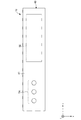
図1は、第1実施の形態に係る検査装置10の構成を模式的に示す図である。図2は、検査装置10を上面41から見た図を示し、図3は、検査装置10を下面42から見た図を示す。検査装置10は、開口部43から出力される複数の照射光を患者の皮膚に照射し、紅斑が生じる最低照射量である最少紅斑量(MED;Minimal Erythema Dose)や、最少反応量(MRD;Minimal Response Dose)、最小光毒量(MPD;Minimal Phototoxic Dose)を求める検査に用いられる。このような検査は、光線過敏検査とも言われ、光線過敏症患者の診断や紫外線治療に適した紫外線照射量をその照射前に求めることなどを目的として実施される。光線過敏症を診断するための検査では、光線種として紫外線だけでなく、可視光線も用いられる。
First Embodiment
FIG. 1 is a view schematically showing the configuration of an
検査装置10は、光源ユニット20と、照射ユニット30と、筐体40と、制御部50と、電源52と、操作部54と、表示部56とを備える。
The
光源ユニット20は、発光素子22と、基板24と、コリメータレンズ26とを有する。
発光素子22は、LED(Light Emitting Diode)などであり、光線過敏検査に用いる波長の光を出力する。発光素子22は、紫外線治療に用いられる320nm〜400nmの長波長紫外線(UVA波)や、290nm〜320nmの中波長紫外線(UVB波)などを出力する。発光素子22として、例えば中心波長またはピーク波長が約305nmのLEDを用いることで、UVB波の検査に用いることができる。このようなLEDとして、窒化アルミニウムガリウム(AlGaN)系のLEDが知られている。
The
The
発光素子22は、基板24に実装されている。基板24は、例えば、銅(Cu)やアルミニウム(Al)等の放熱性の高い金属で構成される。コリメータレンズ26は、発光素子22から出力される光を平行光に変換する。コリメータレンズ26は、ボールレンズやドラムレンズなどであり、コリメータレンズ26の焦点位置に発光素子22が位置するように配置される。発光素子22が発する光は、コリメータレンズ26により平行光に変換されて照射ユニット30に入射する。
The
照射ユニット30は、複数のビームスプリッタ31〜35を有し、光源ユニット20からの光を複数の照射光に分割して出力する。複数のビームスプリッタ31〜35は、第1方向(x方向)に並んで配置される。複数のビームスプリッタ31〜35は、第1方向に入射する光の一部を第1方向に透過させ、入射する光の一部を第2方向(z方向)に反射させるように配置される。
The
第1ビームスプリッタ31は、光源ユニット20からの光の一部を第1開口45に向けて反射させるように配置される。第2ビームスプリッタ32は、第1ビームスプリッタ31に隣接して配置され、第1ビームスプリッタ31を透過した光の一部を第2開口46に向けて反射させる。第3ビームスプリッタ33は、第2ビームスプリッタ32に隣接して配置され、第2ビームスプリッタ32を透過した光の一部を第3開口47に向けて反射させる。第4ビームスプリッタ34は、第3ビームスプリッタ33に隣接して配置され、第3ビームスプリッタ33を透過した光の一部を第4開口48に向けて反射させる。第5ビームスプリッタ35は、第4ビームスプリッタ34に隣接して配置され、第4ビームスプリッタ34を透過した光の一部を第5開口49に向けて反射させる。
The
複数のビームスプリッタ31〜35は、第1方向に透過する光の一部を順に第2方向に反射させていくことにより、強度が第1方向に順に小さくなる照射光を生成する。例えば、複数のビームスプリッタ31〜35の反射率が50%である場合、出力される照射光の強度は、50%、25%、13%、6%、3%となる。複数のビームスプリッタ31〜35は、このようにして、強度が段階的に小さくなる複数の照射光を生成する。
The plurality of
なお、複数のビームスプリッタ31〜35の反射率は、検査で必要とする照射光の強度に応じて決めることができる。例えば、複数のビームスプリッタ31〜35の反射率を30%、つまり、透過率を70%とすれば、複数のビームスプリッタ31〜35で反射されて出力される照射光として30%、21%、15%、10%、7%の強度が得られる。複数のビームスプリッタの反射率が同じであれば、反射率を小さくすることで第1方向に隣り合う照射光の強度差を小さくできる。一方で、ビームスプリッタの反射率を大きくすれば照射光のダイナミックレンジを大きくすることができる。なお、複数のビームスプリッタ31〜35の反射率はそれぞれ異なる値であってもよい。この場合、目的に合った最小照射量、最大照射量および照射量間隔が得られるように、複数のビームスプリッタ31〜35のそれぞれの反射率が定められることが望ましい。また、照射ユニット30を交換可能に構成し、検査の目的に応じてビームスプリッタの反射率を変更できるようにしてもよい。
The reflectances of the plurality of
複数のビームスプリッタ31〜35のそれぞれは、検査に用いる照射光を出力するための光照射部として機能する。各ビームスプリッタ31〜35に対応する複数の光照射部のそれぞれは、強度が互いに異なる照射光をz方向に出力するように構成される。また、複数の光照射部は、それぞれから出力される照射光の強度がx方向の順に小さくなるように構成される。
Each of the plurality of
筐体40は、光源ユニット20や照射ユニット30などを内部に収容する。筐体40は、例えば、略直方体の箱形形状を有し、金属や樹脂などの材料で成型される。筐体40の上面41には、操作部54および表示部56が設けられ、下面42には、照射光を出力するための開口部43が設けられる。開口部43は、複数のビームスプリッタ31〜35に対応する第1開口45〜第5開口49を有する。第1開口45〜第5開口49は、第1方向に並んで配置されている。
The
制御部50は、操作部54からの入力に基づいて発光素子22の発光を制御する。制御部50は、発光素子22の発光強度や点灯時間といった照射条件を設定するための情報を表示部56に表示させ、操作部54からの入力を通じてこれら条件の設定を受け付ける。制御部50は、例えば、複数の検査モードと各検査モードに対応する照射条件を保持してもよい。制御部50は、複数の検査モードのリストを表示部56に表示させ、操作部54からの入力により検査モードの指定を受け付けることで、指定された検査モードに対応する照射条件の照射光が出力されるように発光素子22を制御してもよい。
The
電源52は、発光素子22や制御部50などに電力を供給する。電源52は、筐体40の内部に収容されるバッテリを含み、例えば、リチウムイオン電池などの充電池を含む。電源52は、充電池を充電するための電源端子を有し、電源端子に接続されるACアダプタ等を通じて充電できるように構成される。なお電源52は、一次電池または二次電池である乾電池を含んでもよい。この場合、筐体40には乾電池を取り付けるための電池ホルダが設けられてもよい。
The
操作部54は、検査装置10による照射の開始および終了の操作や、検査装置10の照射条件を設定するための操作に用いられる。表示部56は、例えば液晶ディスプレイなどで構成され、検査装置10の動作状態や設定される照射条件などを表示する。操作部54は、表示部56とは別の位置に設けられるスイッチやボタンなどで構成されてもよいし、表示部56と一体となったタッチパネルなどで構成されてもよい。
The
つづいて、検査装置10の使用方法について説明する。まず、検査内容に応じた検査モードを設定することで照射条件が決定される。次に、照射対象となる皮膚に下面42が密着するように検査装置10が配置される。上腕や太ももなどの皮膚で検査する場合、腕や脚と検査装置10がベルト等の固定器具や貼付剤などにより固定され、照射中に検査装置10の位置がずれないようにされる。検査装置10と皮膚の間にわずかな隙間が生じてしまう場合、紫外光が周囲に漏れ出さないように、紫外光を遮蔽するカバー(例えば、布製)を検査装置10と照射対象の双方を覆うようにして取り付けてもよい。検査装置10を固定した後、検査光の照射を開始させる。照射が開始されてから予め設定された時間の経過後に照射が自動的に停止される。照射の終了後、検査装置10が外される。検査装置10による照射を受けた皮膚は、所定時間後(例えば、1日〜2日後など)に医師により紅斑の有無が診断され、MED、MRDまたはMPDが特定される。
Then, the usage method of the test |
本実施の形態によれば、照射ユニット30により強度の異なる複数の照射光を生成して同時に皮膚に照射することができるため、照射条件を変えながら個々に検査光を照射していく方法と比べて照射時間を短縮し、検査者の手間を軽減させることができる。これにより、検査にかかる医師および患者の負担を軽減することができる
According to the present embodiment, a plurality of irradiation lights of different intensities can be generated by the
本実施の形態によれば、光源ユニット20の光源としてLEDなどの発光素子22が用いられ、照射ユニット30や電源52などが筐体40の内部に一体的に格納されることから検査装置10を小型化することができる。特に、医療用の紫外線照射装置の光源として一般的に使用されるエキシマランプや蛍光ランプなどを用いる場合と比べて、装置を大幅に小型化することができる。空間的制約などのために大型の光線過敏検査機器をこれまで設置できなかった施設においても、容易に光線過敏試験が実施できるようになる。
According to the present embodiment, the
本実施の形態によれば、検査装置10が小型であるため、上腕や太ももなどに検査装置10を密着させて検査を実施できる。そのため、検査のために患者をベッドに寝かせて背中を露出させるなどの準備をしなくて済むようになる。また、検査装置10を上腕に固定させる場合には、検査光の照射中であっても患者が移動可能であるため、診察室の外に移動することも可能となる。さらに検査装置10では有害な紫外光が周囲に漏れることがないため、他の患者やスタッフのいないベッド付きの個室(診察室)ではなく、待合室などを利用して検査光の照射を実施することができる。さらに言えば、光線照射を実施するための専用の閉鎖空間を用意する必要もなくなる。これにより、検査にかかる医師および患者の負担を軽減することができる。また、検査中において診察室を占有しなくて済むことから、次の患者の診察の待ち時間を短くすることもできる。
According to the present embodiment, since the
本実施の形態によれば、検査装置10を検査対象となる皮膚に密着させて検査を実施できるため、開口部43に対向する皮膚に狙った通りの照射量で検査光を照射できる。従来の多孔板を用いる検査方法では、多孔板と皮膚の間の隙間が生じることにより検査光が窓孔の周囲に漏れて他の窓孔に対応する部分の皮膚に光が当たってしまい、正確な光線量が対象皮膚に照射されず、正確な検査結果が得られないことがあった。一方、本実施の形態では、小型の検査装置10を皮膚に密着させて用いるため、複数の開口45〜49のそれぞれから出力される検査光が隣接する領域に漏れないようにできる。これにより、検査の正確性および安全性を高めることができる。
According to the present embodiment, since the inspection can be performed by bringing the
(変形例1)
図4は、変形例に係る検査装置10の構成を模式的に示す図である。本変形例は、光源ユニット20と照射ユニット30が第2方向(z方向)に並ぶように配置される点で上述の実施の形態と相違する。以下、本変形例について上述の実施の形態との相違点を中心に説明する。
(Modification 1)
FIG. 4: is a figure which shows typically the structure of the
光源ユニット20は、発光素子22から出力されてコリメータレンズ26により平行にされた光が第1ビームスプリッタ31に向かってz方向に入射するように配置される。発光素子22、コリメータレンズ26および第1ビームスプリッタ31は、図示されるようにz方向に一列に並ぶように設けられる。また、発光素子22が実装される基板24は、筐体40の上面41を構成する部材に固定されるように設けられる。
The
照射ユニット30は、複数のビームスプリッタ31〜35がx方向に並ぶように構成される。複数のビームスプリッタ31〜35は、筐体40の下面42を構成する部材に固定されるように設けられる。第1ビームスプリッタ31は、光源ユニット20からの光の一部を第1開口45に向けてz方向に透過させ、別の一部を第2ビームスプリッタ32に向けてx方向に反射させるように設けられる。第2ビームスプリッタ32、第3ビームスプリッタ33、第4ビームスプリッタ34および第5ビームスプリッタ35は、隣接するビームスプリッタからの光の一部を対応する開口46〜49に向けてz方向に反射させるように設けられる。
The
制御部50および電源52は、照射ユニット30とz方向に並ぶように配置され、第2ビームスプリッタ32、第3ビームスプリッタ33、第4ビームスプリッタ34および第5ビームスプリッタ35と、筐体40の上面41を構成する部材との間の位置に設けられる。
The
本変形例によれば、照射ユニット30が下面42側に設けられ、光源ユニット20、制御部50および電源52などの照射ユニット30以外の構成が上面41側に設けられるため、上述の実施の形態と比べて下面42の面積を小さくできる。人体には、平面として存在する皮膚はほとんどなく、近似的に平面とみなすことのできる箇所も限られている。そのため、仮に下面42の面積が大きいと、検査装置10を皮膚に密着させることが困難となり、検査装置10の実用性が低下してしまう。本変形例によれば、下面42の面積を小さくできるため、検査装置10を患者の皮膚に密着させやすくすることができ、検査装置10の利便性を高めることができる。また、検査装置10を皮膚に密着させることで周囲への光漏れを防ぐとともに装置の位置ずれを防ぐことができるため、検査の正確性および安全性を高めることができる。
According to the present modification, the
(変形例2)
図5は、変形例に係る検査装置10の構成を模式的に示す図である。本変形例は、光源ユニット20と照射ユニット30を備えるヘッド部70と、制御部50や電源52を備える本体部72とが分離されている点で上述の実施の形態と相違する。以下、本変形例について上述の実施の形態との相違点を中心に説明する。
(Modification 2)
FIG. 5: is a figure which shows typically the structure of the
検査装置10は、ヘッド部70と、本体部72と、ケーブル74とを備える。ヘッド部70は、光源ユニット20と、照射ユニット30と、ヘッド側筐体40aと、表示部56と、を含む。本体部72は、本体側筐体40bと、制御部50と、電源52と、操作部54と、を含む。ヘッド部70と本体部72は、ケーブル74によって電気的に接続されている。
The
本変形例によれば、検査装置10がヘッド部70と本体部72に分離されるため、上述の実施の形態と比べてヘッド部70を小型化することができる。これにより、患者の皮膚に接触する下面42の面積を小さくすることができる。したがって、本変形例においても、上述の変形例と同様に、検査装置10を患者の皮膚に密着させやすくすることができ、検査装置10の利便性を高めることができる。また、検査装置10を皮膚に密着させることで周囲への光漏れを防ぐとともに装置の位置ずれを防ぐことができるため、検査の正確性および安全性を高めることができる。
According to this modification, since the
(変形例3)
図6は、変形例に係る検査装置10の構成を模式的に示す外観斜視図であり、下面42の構成を示す。本変形例は、下面42から突出するように枠体80が設けられる点で上述の実施の形態と相違する。以下、本変形例について上述の実施の形態との相違点を中心に説明する。
(Modification 3)
FIG. 6 is an external perspective view schematically showing the configuration of the
筐体40は、下面42に設けられる枠体80を有する。枠体80は、開口部43を囲むように設けられる外周枠82と、複数の開口45〜49のそれぞれの間を仕切るように設けられる仕切枠84とを含む。枠体80は、筐体40と同じ樹脂材料や金属材料で構成される。
The
検査装置10は、枠体80の端面86が患者の皮膚に接触するようにして使用される。このとき、枠体80は、複数の開口45〜49のそれぞれから出力される検査光が枠体80によって囲われる領域の皮膚に照射されるようにし、複数の開口45〜49のそれぞれから出力される検査光が隣接する領域に漏れないようにする。枠体80は、例えば、第1開口45から出力される検査光の全てが第1開口45に対向する皮膚に照射され、隣接する第2開口46に対向する皮膚に照射されないようにする。
The
本変形例によれば、下面42と皮膚との隙間を枠体80によって塞ぐことができるため、開口部43に対向する皮膚に狙った通りの照射量で検査光を照射することができ、検査装置10の周囲に有害な紫外光が漏れ出すことを防ぐこともできる。また、各開口45〜49からの光線漏れを防ぐことによって、各開口45〜49の周囲の照射量が設定値よりも増加して対象皮膚への照射量が不正確となることを防ぐこともできる。これにより、検査装置10を用いた検査の精度を高めるとともに、検査の安全性を高めることができる。また、枠体80を設けることで、皮膚との接触面積を小さくすることができる。
According to this modification, since the gap between the
本変形例によれば、枠体80を押し付けながら検査をすることで、検査光が照射された領域の周りに圧痕をつけて検査された領域の目印とすることができる。このとき、目印となる圧痕と照射位置とのずれがないため、検査の正確性を高めることができる。なお、圧痕を付ける代わりに、枠体80の端面86にインクを付けて検査をすることで、検査領域に枠体80の形状に対応したマークが残るようにしてもよい。もしくは、検査実施前に検査対象となる皮膚に枠体80の形状に対応したマークを水性ペンやシールなどで付けておき、そのマークに沿って検査装置10を配置して検査を実施してもよい。
According to this modification, by performing the inspection while pressing the
(変形例4)
図7は、変形例に係る検査装置10の構成を模式的に示す図である。本変形例は、光源ユニット20が複数の発光素子22a,22b,22cを有する点で上述の実施の形態と相違する。以下、本変形例について上述の実施の形態との相違点を中心に説明する。
(Modification 4)
FIG. 7 is a view schematically showing a configuration of an
光源ユニット20は、複数の発光素子22a,22b,22cと、基板24と、複数のコリメータレンズ26a,26b,26cと、複数のビームコンバイナ28a,28b,28cを有する。本変形例に係る光源ユニット20は、中心波長またはピーク波長がそれぞれ異なる複数の発光素子を組み合わせることで、波長域の広い検査光の生成を可能にする。
The
複数の発光素子22a〜22cは、中心波長またはピーク波長がそれぞれ異なるLEDである。例えば、第1発光素子22aは、中心波長またはピーク波長が340nmとなるAlGaN系のLEDであり、第2発光素子22bは、中心波長またはピーク波長が365nmとなるAlGaN系またはGaN系のLEDであり、第3発光素子22cは、中心波長またはピーク波長が385nmとなるGaN系のLEDである。これら三波長の光を合成することで、320nm〜400nmのUVA波の波長域をカバーする検査光を生成できる。
The plurality of
複数のコリメータレンズ26a〜26cは、対応する発光素子22a〜22cから出力される光を平行光に変換する。複数のビームコンバイナ28a〜28cは、コリメータレンズ26a〜26cのそれぞれから出力される平行光を合成する。複数のビームコンバイナ28a〜28cのそれぞれは、例えば、ビームスプリッタなどの光学素子である。
The plurality of
第1ビームコンバイナ28aは、第1コリメータレンズ26aからの平行光を第1方向(x方向)に反射させる。第2ビームコンバイナ28bは、第2コリメータレンズ26bからの平行光を第1方向に反射させるとともに、第1ビームコンバイナ28aからの平行光を第1方向に透過させる。第3ビームコンバイナ28cは、第3コリメータレンズ26cからの平行光を第1方向に反射させるとともに、第2ビームコンバイナ28bからの平行光を第1方向に透過させる。第3ビームコンバイナ28cからの平行光は、照射ユニット30に入射する。これにより、複数の発光素子22a〜22cからの光を合成した合成光を照射ユニット30に提供できる。照射ユニット30は、光源ユニット20から出力される合成光を複数の照射光に分割して出力する。
The
本変形例によれば、複数の発光素子22a〜22cからの光を合成した合成光を検査光として用いることができる。これにより、一つの発光素子が出力可能な波長域よりも広い波長域を必要とする検査であっても、その検査に適した検査光を提供することができる。特に、UVB波の検査と比べて波長域の広いUVA波の検査への対応が可能となる。したがって、本変形例によれば、UVA波などの広い波長域の検査光を用いる光線過敏検査において、上述の実施の形態と同様の効果を奏することができる。
According to this modification, it is possible to use combined light obtained by combining the light from the plurality of
本変形例によれば、小型の発光素子を組み合わせることで、光線過敏試験や光線治療に従来から用いられてきた照射装置と同等もしくは近似した波長特性の検査光を提供することができる。LEDなどの発光素子の出力光は、波長帯域が狭く単色性が高いため、従来から用いられてきた照射装置とは波長特性が異なる。そのため、発光素子を単独で使用する場合、波長特性の違いから、これまでの光線過敏試験や光線治療における知見がそのまま利用できないおそれがある。例えば、光毒性を有するソラレンを利用するPUVA療法などでは、UVA波を利用することを前提としているため、UVA波を用いた試験が欠かせない。本実施の形態によれば、複数の発光素子を組み合わせることで、小型でかつ従来の照射装置と同等の波長特性を有する検査装置を提供できるため、これまでの知見に基づいて適正かつ安全性の高い試験を実施することができる。また、検査装置10の試験結果に基づいて従来の照射装置を用いた治療を行う場合にも、より的確にMEDやMPDを求めることができる。
According to this modification, by combining small-sized light emitting elements, it is possible to provide inspection light of the wavelength characteristic equal to or similar to the irradiation device conventionally used in the photosensitivity test and the phototherapy. The output light of a light emitting element such as an LED has a narrow wavelength band and high monochromaticity, and thus has different wavelength characteristics from the conventionally used irradiation devices. Therefore, when a light emitting element is used alone, there is a possibility that the knowledge in the conventional photosensitivity test and phototherapy can not be used as it is because of the difference in wavelength characteristics. For example, since PUVA therapy using psoralen having phototoxicity is premised on using UVA wave, it is essential to test using UVA wave. According to the present embodiment, by combining a plurality of light emitting elements, it is possible to provide a compact inspection apparatus having wavelength characteristics equivalent to those of the conventional irradiation apparatus. High testing can be performed. Moreover, also when performing the treatment using the conventional irradiation apparatus based on the test result of the test |
(変形例5)
図8は、変形例に係る検査装置10の構成を模式的に示す図である。本変形例は、光源ユニット20と照射ユニット30がそれぞれ別の筐体に設けられ、光源ユニット20と照射ユニット30との間が光ファイバ60で接続されている点で上述の変形例と相違する。以下、本変形例について上述の実施の形態および変形例との相違点を中心に説明する。
(Modification 5)
FIG. 8 is a view schematically showing a configuration of an
光源ユニット20は、複数の発光素子22a,22b,22cと、基板24と、複数のコリメータレンズ26a,26b,26cと、複数のビームコンバイナ28a,28b,28cを有する。光源ユニット20は、さらに、光源側カップリングレンズ62と、光源側コネクタ64とを有する。光源ユニット20は、光源ユニット筐体40cに収容されている。
The
光源側コネクタ64は、光ファイバ60の入力端を接続するための光コネクタである。光源側カップリングレンズ62は、第3ビームコンバイナ28cから出力される合成光を光源側コネクタ64に接続される光ファイバ60に入射させる。光源側カップリングレンズ62は、ボールレンズやドラムレンズなどであり、光源側カップリングレンズ62の焦点位置に光源側コネクタ64が位置するように配置される。
The
照射ユニット30は、複数のビームスプリッタ31〜35を有する。照射ユニット30は、さらに、照射側カップリングレンズ66と、照射側コネクタ68とを有する。照射ユニット30は、照射ユニット筐体40dに収容されている。照射ユニット筐体40dには、複数のビームスプリッタ31〜35で反射されて出力される照射光を通すための開口部43が設けられている。
The
照射側コネクタ68は、光ファイバ60の出力端を接続するための光コネクタである。照射側カップリングレンズ66は、照射側コネクタ68に接続される光ファイバ60から出射される光を平行光に変換する。照射側カップリングレンズ66は、ボールレンズやドラムレンズなどであり、照射側カップリングレンズ66の焦点位置に照射側コネクタ68が位置するように配置される。照射側カップリングレンズ66により変換された平行光は、第1ビームスプリッタ31に入射する。
The
本変形例によれば、光源ユニット20と照射ユニット30が別体となっているため、両者を一体化させている場合と比べて、患者の皮膚に当てて使用する部分をさらに小型化できる。したがって、照射ユニット30を上腕や太ももに固定して使用する場合の患者の負担を軽減させることができる。
According to this modification, since the
本変形例によれば、光源ユニット20と照射ユニット30が別体となっているため、異なる特性を有する複数種類の光源ユニットおよび照射ユニットを組み合わせて使用することができる。例えば、照射光の波長を変えたい場合に、出力波長が異なる光源ユニット20に取り替えるだけで共通の照射ユニット30を用いて検査できる。また、照射光の強度差を変えたい場合に、ビームスプリッタの反射率が異なる照射ユニット30に取り替えるだけで共通の光源ユニット20を用いて検査できる。また、光源ユニットとして、LEDなどの発光素子以外のランプ等を使用した光源装置を用いることもできる。
According to this modification, since the
(第2の実施の形態)
図9は、第2の実施の形態に係る検査装置110の構成を模式的に示す図である。図10は、図9のA−A線断面を示し、図9は、図10のB−B線断面に対応する。検査装置110は、複数の光源ユニット121,122,123と、複数の照射ユニット131,132,133とを有する点で上述の実施の形態と相違する。以下、上述の実施の形態および変形例との相違点を中心に説明する。
Second Embodiment
FIG. 9 is a view schematically showing a configuration of an
複数の光源ユニット121〜123は、上述の実施の形態または変形例に係る光源ユニット20と同様の構成を有するが、それぞれが異なる波長域の光を出力するように構成される。第1光源ユニット121は、第1波長域の紫外光を含む第1検査光151を出力するように構成され、具体的には、290nm〜320nmの波長域のUVB波を出力するように構成される。第1光源ユニット121は、例えば、中心波長またはピーク波長が約305nmのLEDを発光素子として有し、図1に示す光源ユニット20と同様に構成される。
The plurality of
第2光源ユニット122は、第1波長域より長波長側の第2波長域の紫外光を含む第2検査光152を出力するように構成され、具体的には、320nm〜400nmの波長域のUVA波を出力するように構成される。第2光源ユニット122は、例えば、中心波長またはピーク波長がそれぞれ340nm、365nm、385nmとなる三つのLEDを発光素子として有し、図7に示す光源ユニット20と同様に構成される。
The second
第3光源ユニット123は、可視光を含む第3検査光153を出力するように構成され、具体的には、波長が400nm以上の可視光域の光を出力するように構成される。第3光源ユニット123は、例えば、それぞれが赤色、緑色、青色の光を出力する三つのLEDを発光素子として有し、図7に示す光源ユニット20と同様の構成を有する。この場合、第3光源ユニット123からは疑似的な白色光が出力される。なお、第3光源ユニット123は、可視光域にわたって連続的なスペクトルを有する光が出力可能な白熱電球などを発光素子として用いてもよい。この場合、第3光源ユニット123には、白熱電球が発する熱線を遮断するための赤外線(IR)カットフィルタが設けられることが望ましい。
The third
複数の照射ユニット131〜133は、上述の実施の形態または変形例に係る照射ユニット30と同様に構成される。第1照射ユニット131は、第1方向(x方向)に並んで配置される複数のビームスプリッタ136を有し、第1光源ユニット121からの第1検査光151が入力される。第1検査光151は、第1照射ユニット131の複数のビームスプリッタ136により複数の第1照射光156に分割され、筐体140の第1開口部143から第2方向(z方向)に出力される。
The plurality of
第2照射ユニット132は、第1方向に並んで配置される複数のビームスプリッタ137を有し、第2光源ユニット122からの第2検査光152が入力される。第2検査光152は、第2光源ユニット122の複数のビームスプリッタ137により複数の第2照射光157に分割され、筐体140の第2開口部144から第2方向に出力される。
The
第3照射ユニット133は、第1方向に並んで配置される複数のビームスプリッタ138を有し、第3光源ユニット123からの第3検査光153が入力される。第3検査光153は、第3光源ユニット123の複数のビームスプリッタ138により複数の第3照射光158に分割され、筐体140の第3開口部145から第2方向に出力される。
The
複数の光源ユニット121〜123は、第1方向と第2方向の双方と交差する第3方向(y方向)に並んで配置されている。同様に、複数の照射ユニット131〜133は、第3方向に並んで配置されている。複数の光源ユニット121〜123と複数の照射ユニット131〜133は、筐体140の内部に収容されている。
The plurality of
図11は、検査装置110を下面142から見た図を示す。図示されるように、第1開口部143は、第1照射ユニット131の複数のビームスプリッタ136に対応して第1方向(x方向)に並んで配置される複数の開口を有する。同様に、第2開口部144は、第2照射ユニット132の複数のビームスプリッタ137に対応して第1方向に並んで配置される複数の開口を有する。第3開口部145は、第3照射ユニット133の複数のビームスプリッタ138に対応して第1方向に並んで配置される複数の開口を有する。第1開口部143、第2開口部144および第3開口部145は、第3方向(y方向)に並んで配置される。したがって、筐体140の下面142に設けられる複数の開口は、マトリックス状にx方向およびy方向に並んで配置される。
FIG. 11 shows the
以上の構成により、検査装置110は、マトリックス状にx方向およびy方向に並んで配置される複数のビームスプリッタを有する。各ビームスプリッタが光照射部として機能ることから、検査装置110は、マトリックス状またはアレイ状に配置される複数の光照射部を有すると言える。この複数の光照射部のそれぞれは、波長特性および強度の少なくとも一方が互いに異なる照射光を第2方向(z方向)に出力する。
According to the above configuration, the
本実施の形態によれば、光線過敏検査に用いる三つの波長域の検査光のそれぞれを強度の異なる複数の照射光に分割して同時に照射することができる。光線過敏検査では、一般に、UVB波、UVA波、可視光の三つの波長域の光が使用され、それぞれの波長域の光に対して皮膚の反応が生じる最低照射量が求められる。本実施の形態によれば、このような三つの波長域の光を同時に照射して検査することができるので、それぞれの波長域の光を個別に照射する場合と比べて検査時間を短くすることができる。これにより、医師および患者の検査負担を軽減することができる。光線療法を実施する前段階の検査としてMEDまたはMPDを測定を行う場合にも、医師および患者の検査負担を軽減できる。 According to the present embodiment, it is possible to divide each of the inspection light of the three wavelength ranges used for the photosensitivity test into a plurality of irradiation lights having different intensities and simultaneously irradiate them. In the photosensitivity test, generally, light of three wavelength ranges of UVB wave, UVA wave, and visible light is used, and the minimum irradiation dose at which the skin reaction occurs to the light of each wavelength range is determined. According to the present embodiment, it is possible to simultaneously irradiate and inspect light in such three wavelength ranges, so the inspection time can be shortened as compared with the case where the light in each wavelength range is individually irradiated. Can. This can reduce the inspection burden on the doctor and the patient. The burden on the doctor and the patient can be reduced even if the MED or MPD is measured as a pre-test for phototherapy.
(第3の実施の形態)
図12は、第3の実施の形態に係る検査装置210の構成を模式的に示す図である。図13は、図12の照射ユニット220を下端面230bから見たときの構成を示す。検査装置210は、照射ユニット220と、制御ユニット250と、ケーブル252とを備える。照射ユニット220は、複数の発光素子221,222,223,224,225と、基板226と、筐体230と、を備える。本実施の形態では、複数の発光素子221〜225および筐体230によって複数の光照射部211,212,213,214,215が構成される点で、上述の実施の形態と相違する。以下、上述の実施の形態および変形例との相違点を中心に説明する。
Third Embodiment
FIG. 12 is a view schematically showing a configuration of an
複数の発光素子221〜225は、第1方向(x方向)に並んで配置され、基板226に実装されている。複数の発光素子221〜225のそれぞれは、第2方向(z方向)に光を出力する。複数の発光素子221〜225のそれぞれは、波長特性の同じ発光素子であってもよいし、互いに波長特性の異なる発光素子でもよい。
The plurality of
筐体230は、外枠板232と、仕切板234a,234b,234c,234dと、を有する。筐体230は、金属材料や樹脂材料で構成される。筐体230は、紫外線反射率の高い材料で構成されることが好ましく、例えばアルミニウム板やPFA(パーフルオロアルコキシアルカン)やPTFE(ポリテトラフルオロエチレン)などのフッ素樹脂の板状部材で構成される。なお、筐体230は、上述の材料以外で基部が構成され、内面が紫外線反射率の高い材料で被覆されてもよい。
The
外枠板232は、第1方向(x方向)に並んでいる複数の発光素子221〜225の外周を囲むようにして設けられ、第2方向(z方向)に延在する。外枠板232は、底面が長方形で中空の角筒形状を有する。複数の仕切板234a〜234dは、外枠板232で囲われる空間を複数の発光素子221〜225のそれぞれの領域に区画するようにして設けられ、第2方向(z方向)に延在する。筐体230の上端面230aは、基板226に取り付けられている。筐体230の下端面230bには、複数の開口245〜249が設けられる。
The
筐体230は、複数の導光路235〜239を形成する。第1導光路235は、第1発光素子221に対応する導光路であり、外枠板232と、第1発光素子221と第2発光素子222の間に設けられる第1仕切板234aにより区画される。第1導光路235は、第1発光素子221から出力される検査光を第1開口245に導く。第1導光路235は、
第1発光素子221の出力光を筐体230の内壁で反射させながら第2方向(z方向)に進行させることにより、第1開口245から出力される照射光の強度分布を均一化させる。
The
By causing the output light of the first
第2導光路236、第3導光路237、第4導光路238および第5導光路239のそれぞれは、第1導光路235と同様に構成される。第2導光路236は、第2発光素子222に対応する導光路であり、外枠板232と、第1仕切板234aと、第2発光素子222と第3発光素子223の間に設けられる第2仕切板234bにより区画される。第3導光路237は、第3発光素子223に対応する導光路であり、外枠板232と、第2仕切板234bと、第3発光素子223と第4発光素子224の間に設けられる第3仕切板234cにより区画される。第4導光路238は、第4発光素子224に対応する導光路であり、外枠板232と、第3仕切板234cと、第4発光素子224と第5発光素子225の間に設けられる第4仕切板234dにより区画される。第1導光路235は、第1発光素子221に対応する導光路であり、外枠板232と、第1発光素子221と第2発光素子222の間に設けられる第1仕切板234aにより区画される。
Each of the second
第2導光路236、第3導光路237、第4導光路238および第5導光路239のそれぞれは、第1導光路235と同様に機能する。第2導光路236は、第2発光素子222から出力される検査光を均一化された照射光に変換して第2開口246から出力させる。第3導光路237は、第3発光素子223から出力される検査光を均一化された照射光に変換して第3開口247から出力させる。第4導光路238は、第4発光素子224から出力される検査光を均一化された照射光に変換して第4開口248から出力させる。第5導光路239は、第5発光素子225から出力される検査光を均一化された照射光に変換して第5開口249から出力させる。
Each of the second
照射ユニット220は、複数の光照射部211〜215を備える。第1光照射部211は、第1発光素子221を発光させることにより、第1開口245から照射光を出力する。第2光照射部212は、第2発光素子222を発光させることにより、第2開口246から照射光を出力する。第3光照射部213は、第3発光素子223を発光させることにより、第3開口247から照射光を出力する。第4光照射部214は、第4発光素子224を発光させることにより、第4開口248から照射光を出力する。第5光照射部215は、第5発光素子225を発光させることにより、第5開口249から照射光を出力する。
The
制御ユニット250は、複数の発光素子221〜225の動作を制御する。制御ユニット250は、実施しようとする検査の内容に適した複数種類の照射光が出力されるように、各発光素子の発光強度を調整する。例えば、複数の発光素子221〜225のそれぞれの発光強度が第1方向(x方向)の順に小さくなるように各発光素子を点灯させることによって、複数の光照射部211〜215のそれぞれが出力する照射光の強度が第1方向(x方向)の順に小さくなるようにする。
The
本実施の形態によれば、複数の発光素子221〜225の発光強度を異ならせることで、光線過敏試験に必要とされる強度の異なる複数の照射光を同時に照射することができる。また、複数の発光素子221〜225として波長特性の異なるLEDを用いることで、光線過敏試験に必要とされる波長帯域の異なる複数の照射光を同時に照射することができる。したがって、上述の実施の形態および変形例と同様に、照射条件を変えながら個々に検査光を照射していく方法と比べて照射時間を短縮し、検査者の手間を軽減させることができるとともに、検査にかかる医師および患者の負担を軽減させることができる。
According to the present embodiment, by making the light emission intensities of the plurality of
本実施の形態によれば、複数の発光素子221〜225の出力光のそれぞれが筐体230を通じて出力されるため、簡易な構造によって強度分布が均一化された照射光を皮膚に照射することができる。照射光の強度分布が均一化されることにより、照射ムラが生じて部分的に強い光が照射されて炎症等が生じたり、意図する強度の光が照射されないことによって診断が困難となったりすることを防ぐことができる。したがって、本実施の形態によれば、光線過敏試験の安全性および信頼性を高めることができる。
According to the present embodiment, each of the output lights of the plurality of
本実施の形態によれば、照射対象となる皮膚に筐体230の下端面230bが接触するように用いることができるため、照射光の漏れを防いで、各照射部に対向する所定領域の皮膚に狙った通りの照射量で検査光を照射できる。また、上述の枠体80と同様に筐体230を用いることで、検査された領域に目印を付けることができる。したがって、検査装置210によれば、検査精度および検査の安全性を高めることができる。
According to the present embodiment, since the
なお、各光照射部211〜215に含まれる発光素子の数は、一つであってもよいし、複数であってもよい。例えば、第1光照射部211に波長特性の異なる複数の発光素子を設けることにより、UVA波のような波長域の広い照射光を出力させることができる。また、可視光、UVA波、UVB波のそれぞれに対応できるように、波長特性の互いに異なる多数の発光素子を第1光照射部211に設けてもよい。同様に、他の光照射部212〜215のそれぞれについても、複数の発光素子を設けてもよい。
The number of light emitting elements included in each of the
以上、本発明を実施例にもとづいて説明した。本発明は上記実施の形態に限定されず、種々の設計変更が可能であり、様々な変形例が可能であること、またそうした変形例も本発明の範囲にあることは、当業者に理解されるところである。 The present invention has been described above based on the embodiments. It is understood by those skilled in the art that the present invention is not limited to the above embodiment, and various design changes are possible, various modifications are possible, and such modifications are also within the scope of the present invention. It is about
上述の実施の形態および変形例では、一つの照射ユニットが5個のビームスプリッタを有する場合を例示した。さらなる変形例においては、照射ユニットに含まれるビームスプリッタの数およびビームスプリッタによって分割される照射光の数が4以下であってもよいし、6以上であってもよい。 In the above-mentioned embodiment and modification, the case where one irradiation unit has five beam splitters was illustrated. In a further modification, the number of beam splitters included in the illumination unit and the number of illumination beams split by the beam splitter may be four or less, or six or more.
上述の実施の形態および変形例では、三つの発光素子を用いてUVA波の波長域を実現する場合を例示した。さらなる変形例においては、中心波長またはピーク波長の異なる四つ以上の発光素子を組み合わせることによりUVA波の波長域を実現してもよい。また、中心波長またはピーク波長の異なる複数の発光素子を組み合わせることによりUVB波の波長域を実現してもよい。 In the above-mentioned embodiment and modification, the case where the wavelength range of a UVA wave was realized using three light emitting elements was illustrated. In a further modification, the wavelength range of the UVA wave may be realized by combining four or more light emitting elements having different center wavelengths or peak wavelengths. In addition, the wavelength range of the UVB wave may be realized by combining a plurality of light emitting elements having different center wavelengths or peak wavelengths.
上述の実施の形態および変形例では、一つの照射ユニットが一つの波長域を実現できるように構成される場合を例示した。さらなる変形例においては、一つの照射ユニットによって複数の波長域、例えば、可視光、UVA波、UVB波のそれぞれの波長域を実現できるように、これらの波長域をカバーするために必要な複数種類の発光素子が一つの照射ユニット内に設けられてもよい。また、操作部からの入力に応じて、照射光の強度および波長特性を変化させることができるようにしてもよい。これにより、試験すべき内容に応じて、適切な波長特性を有する照射光を出力させることができる。 In the above-mentioned embodiment and modification, the case where one irradiation unit was constituted so that one wavelength range could be realized was illustrated. In a further variant, a plurality of types necessary to cover these wavelength ranges so that one wavelength unit can realize a plurality of wavelength ranges, for example, visible light, UVA waves, UVB waves, respectively, by one irradiation unit The light emitting device of the present invention may be provided in one irradiation unit. Further, the intensity and wavelength characteristics of the irradiation light may be changed according to the input from the operation unit. Thereby, it is possible to output irradiation light having appropriate wavelength characteristics according to the contents to be tested.
上述の実施の形態および変形例では、一つのビームスプリッタに対して一つの開口が設けられる場合を例示した。さらなる変形例においては、複数のビームスプリッタに対して一つの開口が設けられてもよい。例えば、図1に示す検査装置10において、開口部43として複数の開口45〜49を設ける代わりに第1方向(x方向)に長い開口を設けることとしてもよい。
In the above-mentioned embodiment and modification, the case where one opening was provided to one beam splitter was illustrated. In a further variant, one aperture may be provided for a plurality of beam splitters. For example, in the
上述の実施の形態および変形例では、複数の光照射部のそれぞれから出力される照射光を個別に囲むようにして設けられる枠体が、矩形状ないし格子状に構成される場合を示した。さらなる変形例においては、枠体が円筒状に構成されてもよいし、底面が三角形や六角形となる角筒状に構成されてもよい。 In the above-mentioned embodiment and modification, the case where the frame provided so that the irradiation light outputted from each of a plurality of light irradiation parts was surrounded individually was constituted in the shape of a rectangle or lattice is shown. In a further modification, the frame may be configured in a cylindrical shape, or may be configured in a rectangular tube shape whose bottom surface is a triangle or a hexagon.
10…検査装置、20…光源ユニット、22…発光素子、30…照射ユニット、31〜35…ビームスプリッタ、110…検査装置、121…第1光源ユニット、122…第2光源ユニット、123…第3光源ユニット、131…第1照射ユニット、132…第2照射ユニット、133…第3照射ユニット、151…第1検査光、152…第2検査光、153…第3検査光、156…第1照射光、157…第2照射光、158…第3照射光、210…検査装置、220…照射ユニット。
DESCRIPTION OF
Claims (5)
光源ユニットと、
第1方向に並んで配置される複数のビームスプリッタを有し、前記光源ユニットからの光を前記複数のビームスプリッタにより互いに強度の異なる複数の照射光に分割し、前記第1方向に並んで配置される複数の光照射部のそれぞれから強度の異なる照射光を前記第1方向と交差する第2方向に出力させる照射ユニットと、を備えることを特徴とする検査装置。 An examination apparatus for examining skin photosensitivity,
A light source unit,
It has a plurality of beam splitters arranged side by side in a first direction, and the light from the light source unit is divided into a plurality of irradiation lights of different intensities by the plurality of beam splitters , and arranged side by side in the first direction inspection system, wherein a plurality of the irradiation unit which outputs different irradiation light intensity from each of the light irradiation unit in the second direction crossing the first direction, further comprising a being.
前記第1波長域より長波長側の第2波長域の紫外光を含む第2検査光を出力する第2光源ユニットと、
可視光を含む第3検査光を出力する第3光源ユニットと、
前記第1方向に並んで配置される複数のビームスプリッタを有し、前記第2検査光を複
数の第2照射光に分割して前記第2方向に出力する第2照射ユニットと、
前記第1方向に並んで配置される複数のビームスプリッタを有し、前記第3検査光を複
数の第3照射光に分割して前記第2方向に出力する第3照射ユニットと、をさらに備え、
前記第1照射ユニット、前記第2照射ユニットおよび前記第3照射ユニットは、前記第1方向および前記第2方向の双方と交差する第3方向に並んで配置されることを特徴とする請求項1から4のいずれか一項に記載の検査装置。 The light source unit is a first light source unit that outputs first inspection light including ultraviolet light in a first wavelength range, and the irradiation unit divides the first inspection light into a plurality of first irradiation lights to be divided. It is a first irradiation unit that outputs in a second direction intersecting the first direction,
A second light source unit that outputs a second inspection light including ultraviolet light in a second wavelength range longer than the first wavelength range;
A third light source unit that outputs a third inspection light including visible light;
A second irradiation unit having a plurality of beam splitters arranged side by side in the first direction, and dividing the second inspection light into a plurality of second irradiation lights and outputting the second inspection light in the second direction;
And a third irradiation unit having a plurality of beam splitters arranged in the first direction, and dividing the third inspection light into a plurality of third irradiation lights and outputting the third irradiation light in the second direction. ,
The first irradiation unit, the second irradiation unit and the third illumination unit, according to claim 1, characterized in that it is arranged in a third direction intersecting with both the first direction and the second direction The inspection apparatus as described in any one of to 4 .
Priority Applications (5)
| Application Number | Priority Date | Filing Date | Title |
|---|---|---|---|
| JP2015184239A JP6547188B2 (en) | 2015-09-17 | 2015-09-17 | Photosensitivity tester |
| CN201680052537.XA CN108024801A (en) | 2015-09-17 | 2016-08-26 | Light allergy check device |
| EP16846228.1A EP3351183B1 (en) | 2015-09-17 | 2016-08-26 | Photosensitivity testing device |
| PCT/JP2016/075011 WO2017047357A1 (en) | 2015-09-17 | 2016-08-26 | Photosensitivity testing device |
| US15/920,058 US11064935B2 (en) | 2015-09-17 | 2018-03-13 | Photosensitivity test device |
Applications Claiming Priority (1)
| Application Number | Priority Date | Filing Date | Title |
|---|---|---|---|
| JP2015184239A JP6547188B2 (en) | 2015-09-17 | 2015-09-17 | Photosensitivity tester |
Publications (2)
| Publication Number | Publication Date |
|---|---|
| JP2017056036A JP2017056036A (en) | 2017-03-23 |
| JP6547188B2 true JP6547188B2 (en) | 2019-07-24 |
Family
ID=58289102
Family Applications (1)
| Application Number | Title | Priority Date | Filing Date |
|---|---|---|---|
| JP2015184239A Active JP6547188B2 (en) | 2015-09-17 | 2015-09-17 | Photosensitivity tester |
Country Status (5)
| Country | Link |
|---|---|
| US (1) | US11064935B2 (en) |
| EP (1) | EP3351183B1 (en) |
| JP (1) | JP6547188B2 (en) |
| CN (1) | CN108024801A (en) |
| WO (1) | WO2017047357A1 (en) |
Families Citing this family (3)
| Publication number | Priority date | Publication date | Assignee | Title |
|---|---|---|---|---|
| JP6709439B2 (en) * | 2016-04-13 | 2020-06-17 | 公立大学法人名古屋市立大学 | UV irradiator for measuring UV sensitivity |
| JP7067742B2 (en) * | 2018-01-18 | 2022-05-16 | 日機装株式会社 | Photosensitivity inspection device |
| CN109820489A (en) * | 2019-04-04 | 2019-05-31 | 深圳光秀医疗科技有限公司 | A kind of skin detection device |
Family Cites Families (19)
| Publication number | Priority date | Publication date | Assignee | Title |
|---|---|---|---|---|
| JPS504988B1 (en) * | 1970-10-16 | 1975-02-26 | ||
| JPS504987B1 (en) * | 1970-10-16 | 1975-02-26 | ||
| JPH0788113A (en) * | 1993-03-18 | 1995-04-04 | Clinical Supply:Kk | Numerous hole exposure device |
| US6251100B1 (en) * | 1993-09-24 | 2001-06-26 | Transmedica International, Inc. | Laser assisted topical anesthetic permeation |
| US7201764B2 (en) * | 2001-03-06 | 2007-04-10 | Lexington Lasercomb Ip Ag | Apparatus and method for stimulating hair growth |
| US6497719B2 (en) * | 2001-03-06 | 2002-12-24 | Henry Pearl | Apparatus and method for stimulating hair growth |
| US6989023B2 (en) * | 2003-07-08 | 2006-01-24 | Oralum, Llc | Hygienic treatments of body structures |
| JP2006000383A (en) * | 2004-06-17 | 2006-01-05 | Yayoi:Kk | Exposure dose measuring implement for ultraviolet treatment |
| CN2719223Y (en) * | 2004-08-30 | 2005-08-24 | 上海希格玛高技术有限公司 | Skin photosensitivity measuring device |
| JP4639266B2 (en) * | 2004-09-21 | 2011-02-23 | Necライティング株式会社 | Ultraviolet irradiation apparatus and ultraviolet irradiation apparatus |
| WO2006049192A1 (en) * | 2004-11-05 | 2006-05-11 | Ya-Man Ltd. | Skin treatment apparatus |
| CN101097261A (en) * | 2006-06-28 | 2008-01-02 | 陈笠 | Ultraviolet ray intelligent monitoring methods and intelligent monitoring plant thereof |
| WO2008083305A2 (en) * | 2006-12-29 | 2008-07-10 | Palomar Medical Technologies, Inc. | Devices for fractional ablation of tissue |
| WO2009050632A1 (en) * | 2007-10-16 | 2009-04-23 | Koninklijke Philips Electronics N.V. | Apparatus, systems and methods for production and integration of compact illumination schemes |
| EP3556291A1 (en) * | 2008-08-07 | 2019-10-23 | University of Massachusetts | Spectroscopic sensors |
| JP2010082040A (en) * | 2008-09-30 | 2010-04-15 | Fujifilm Corp | Endoscope system |
| JP4898885B2 (en) | 2009-10-09 | 2012-03-21 | 明理 森田 | UV therapy device |
| US10928321B2 (en) * | 2012-03-09 | 2021-02-23 | Ubiquitome Limited | Portable device for detecting molecule(s) |
| WO2013186780A1 (en) * | 2012-06-13 | 2013-12-19 | Hadasit Medical Research Services And Development Ltd. | Devices and methods for detection of internal bleeding and hematoma |
-
2015
- 2015-09-17 JP JP2015184239A patent/JP6547188B2/en active Active
-
2016
- 2016-08-26 EP EP16846228.1A patent/EP3351183B1/en active Active
- 2016-08-26 WO PCT/JP2016/075011 patent/WO2017047357A1/en active Application Filing
- 2016-08-26 CN CN201680052537.XA patent/CN108024801A/en active Pending
-
2018
- 2018-03-13 US US15/920,058 patent/US11064935B2/en active Active
Also Published As
| Publication number | Publication date |
|---|---|
| EP3351183A4 (en) | 2019-03-13 |
| CN108024801A (en) | 2018-05-11 |
| WO2017047357A1 (en) | 2017-03-23 |
| US11064935B2 (en) | 2021-07-20 |
| EP3351183A1 (en) | 2018-07-25 |
| JP2017056036A (en) | 2017-03-23 |
| US20180206779A1 (en) | 2018-07-26 |
| EP3351183B1 (en) | 2020-11-18 |
Similar Documents
| Publication | Publication Date | Title |
|---|---|---|
| CN101744611B (en) | Apparatus for photodynamic therapy and photo detection | |
| JP4521587B2 (en) | Optical diagnostic device with improved illumination uniformity | |
| US8496695B2 (en) | Apparatus and method for photodynamic diagnosis and therapy of skin diseases and light source system thereof | |
| RU2626888C2 (en) | Mobile x-ray machine | |
| JP6547188B2 (en) | Photosensitivity tester | |
| US9168391B2 (en) | Mobile X-ray unit | |
| RU79787U1 (en) | PHYSIOTHERAPEUTIC DEVICE FOR LIGHT AND COLOR THERAPY | |
| Ruiz et al. | Smartphone fluorescence imager for quantitative dosimetry of protoporphyrin-IX-based photodynamic therapy in skin | |
| CN103566476B (en) | For the light source of illumination diagnosis and light therapy | |
| AU681376B2 (en) | Light emitting diode source for photodynamic therapy | |
| KR101214440B1 (en) | Apparatus for photo-diagnosis of skin disease using uniform illumination and illuminating method of the smae | |
| Melo et al. | Light Hazard Measurement on an Ophthalmic Instrument. | |
| RU2649211C2 (en) | Automated laser complex for diagnosis and treatment of diseases by photodynamic therapy in oncology | |
| CN112336457A (en) | Homogenizing laser surface light source device for fluorescent image navigation operation | |
| US20210220665A1 (en) | System and method for quantitative dosimetry of photodynamic therapy in skin | |
| JP6829441B2 (en) | Photosensitivity tester | |
| JP7067742B2 (en) | Photosensitivity inspection device | |
| CN215606241U (en) | Operation navigation device and system | |
| US20240130668A1 (en) | Device and method for measuring skin changes caused by blue light, and blue light irradiation device | |
| CN117918878A (en) | Diagnosis and treatment integrated laser equipment | |
| Boese et al. | Endoscopic filter fluorometer for emission detection of Protoporphyrin IX and its direct precursors in PDT and PDD | |
| CN115530972A (en) | Operation navigation device and system | |
| KR20210059279A (en) | Near Infrared Fluorescence Image Acquisition and Image Projection System for Guiding Cancer Surgery | |
| JP2021182978A (en) | Light source device | |
| Momchilov et al. | Development of low-cost photodynamic therapy device |
Legal Events
| Date | Code | Title | Description |
|---|---|---|---|
| A621 | Written request for application examination |
Free format text: JAPANESE INTERMEDIATE CODE: A621 Effective date: 20180402 |
|
| A131 | Notification of reasons for refusal |
Free format text: JAPANESE INTERMEDIATE CODE: A131 Effective date: 20190115 |
|
| A521 | Request for written amendment filed |
Free format text: JAPANESE INTERMEDIATE CODE: A523 Effective date: 20190305 |
|
| TRDD | Decision of grant or rejection written | ||
| A01 | Written decision to grant a patent or to grant a registration (utility model) |
Free format text: JAPANESE INTERMEDIATE CODE: A01 Effective date: 20190514 |
|
| A61 | First payment of annual fees (during grant procedure) |
Free format text: JAPANESE INTERMEDIATE CODE: A61 Effective date: 20190605 |
|
| R150 | Certificate of patent or registration of utility model |
Ref document number: 6547188 Country of ref document: JP Free format text: JAPANESE INTERMEDIATE CODE: R150 |
|
| S533 | Written request for registration of change of name |
Free format text: JAPANESE INTERMEDIATE CODE: R313533 |
|
| R350 | Written notification of registration of transfer |
Free format text: JAPANESE INTERMEDIATE CODE: R350 |
|
| R250 | Receipt of annual fees |
Free format text: JAPANESE INTERMEDIATE CODE: R250 |
|
| R250 | Receipt of annual fees |
Free format text: JAPANESE INTERMEDIATE CODE: R250 |